Influence of the bifunctional triethoxy-vinyl properties ......Influence of the bifunctional...
186
Influence of the bifunctional triethoxy-vinyl polydimethylsiloxane (PDMS) coupling mechanisms on the wood flour and polypropylene matrices to enhance the properties of wood plastic composites (WPC) Von der Fakultät für Lebenswissenschaften der Technischen Universität Carolo-Wilhelmina zu Braunschweig zur Erlangung des Grades einer Doktorin der Naturwissenschaften (Dr. rer. nat.) genehmigte D i s s e r t a t i o n von Azizah Binti Baharum aus Terengganu / Malaysia
Transcript of Influence of the bifunctional triethoxy-vinyl properties ......Influence of the bifunctional...
Influence of the bifunctional triethoxy-vinyl polydimethylsiloxane (PDMS) coupling mechanisms on the
wood flour and polypropylene matrices to enhance the properties of wood plastic composites (WPC)
Von der Fakultät für Lebenswissenschaften
der Technischen Universität Carolo-Wilhelmina
zu Braunschweig
zur Erlangung des Grades einer
Doktorin der Naturwissenschaften
(Dr. rer. nat.)
genehmigte
D i s s e r t a t i o n
von Azizah Binti Baharum
aus Terengganu / Malaysia
Druckjahr 2012
1. Referent: Professor Dr. Rainer Marutzky
2. Referent: Professor Dr. mult. Dr. h. c. Müfit Bahadir
eingereicht am: 14.11.2011
mündliche Prüfung (Disputation) am: 16.02.2012
Acknowledgements
I gratefully acknowledge the Ministry of Higher Education Malaysia and
National university of Malaysia for sending and sponsoring my study and my family
here in Germany. Without their four-year financial support in the first place, I will
not be here. To Fraunhofer, Wilhelm-Klauditz Institute, Braunschweig for providing
me space and workplace for doing my research and for the one-year financial support
during my thesis writing in the fifth year, thank you. Also equally important to
acknowledge Evonik Goldschmidt GmbH, Essen, Germany, especially to Mrs.
Kathrin Lehmann and Sabic Deutschland GmbH and Co. Gelsenkirchen, Germany
for supplying the materials needed in this research.
I am heartily thankful to my supervisor, Prof. Dr. Rainer Marutzky and my
mentor Dr. Arne Schirp, whose encouragement, guidance and support from the initial
to the final level enabled me to develop an understanding of the subject. It is also a
pleasure to thank those who made the research and this thesis possible, especially
from the VT department of Fraunhofer, WKI Institute: Prof. Dr.-Ing. Volker Thole,
Mr. Volker Ebeling, Mr. Heinz Peter, Mr. Thomas Schwarz and not to forget Mr.
Wagner Bürger and Dr. Stefan Friebel. Special thanks to all my colleagues Anja,
Claudia, Barbora, Helena, Richard, Felix and Andrea who also helped me a lot
during my study in Germany.
My special and sincere thanks to Mr. Zeljan Dujmovic and wife, Mrs.
Sharifah Muhammad for spending their precious times reviewed, upgraded and
proofreading the entire manuscript and their helps during our stay here, in
Braunschweig.
I am very deeply indebted and grateful to my two financial guarantors, Mrs.
Asma Dazni Daniel and Mrs. Nadzirah Abu Samah. Without their guarantees, I could
not further my study. Last but not least, I would like to thank and express my
gratitude to my husband, Ismail bin Wahid who has been so patience, understanding,
supportive, always there for me and always encouraged me in finishing my PhD and
my daughter, Izlin binti Ismail for her understanding, tolerance and love to me as a
mother and student who don’t really have much time together with her, thank you my
dear. My father and all my families and friends in Malaysia, who always supported
and prayed for me, sincerely thanks and May God, bless all of you always.
Lastly, I offer my regards and blessings to all of those who supported me in any
respect during the completion of the research and thesis.

Abstract
The incompatibility problem in combining the contradicting characteristics of
wood and plastic in producing wood plastic composites (WPC) has drawn the
attention of using coupling agents. A most interesting group of coupling agents
concerns bifunctional siloxanes such as the bifunctional triethoxy-vinyl
polydimethylsiloxane (PDMS). The bifunctional PDMS combines a polysiloxane
backbone with bifunctional groups such as triethoxy and vinyl groups. These groups
are not connected prior to compounding with reactions such as hydrolysis and
condensation process as in the case of coupling agents based on anhydride or
isocyanate functions. The influence of specially synthesized bifunctional PDMS
coupling agents on the performance of composites containing 70% wood flour and
30% polypropylene (WF/PP 70/30) was investigated. Comparison with composites
of 30/70 and 50/50 WF/PP composition were made to see whether the PDMS
coupling agent could more effectively react with wood or with PP. Composites were
prepared by compounding treated or untreated WF and PP in a lab scale twin screw
compounder. Flexural strength test, impact test, moisture and water absorption
analysis, morphology and microstructure investigation, fourier transform infrared
analysis and dynamic mechanical analysis were done to determine the properties of
WPCs produced with and without PDMS.
With the support of these investigations the influence of single functionality PDMS
containing vinyl functional group, triethoxy functional group or a mixture of 50/50
composition containing vinyl PDMS and triethoxy PDMS compared to the
bifunctional triethoxy-vinyl PDMS on the mechanical properties and performance of
composites were evaluated. Mechanical properties and performance of bifunctional
triethoxy-vinyl PDMS treated composites with low molecular weight, high molecular
weight and very high molecular weight were also investigated. The optimum amount
of coupling agents ranging from 0.88 wt% to 14 wt% was determined as well.
Dicumylperoxide (DCP) was used as the radical initiator for the bonding reaction of
the vinyl group of the coupling agents with PP.
It was found that the optimum amount of coupling agent for 70/30 WF/PP is about
1.75%. Composites produced with such amounts of bifunctional triethoxy-vinyl
PDMS show the best mechanical properties. Also PDMS with very high molecular
weight gave composites with better mechanical properties compared to composites
treated with single functional groups PDMS coupling agents or bifunctional PDMS
with lower molecular weights. It was rationalized as due to the existence of better
interphase bonding between wood and PP when both vinyl and triethoxy that were
chemically bonded to the PDMS backbone was used comparing to the single
functionality PDMS. Covalent bonding between coupling agent-wood interface
through triethoxy reaction with OH-group of wood during treatment and coupling
agent-PP interface through the reaction of vinyl group with PP initiated by DCP
during compounding might have occurred, thus bridging additional the interfaces of
wood and PP. The better adhesion with bifunctional triethoxy-vinyl PDMS compared
with the mixture of single functionality PDMS could be explained by improvements

of activation energies and modifications of glass transition temperatures. The
microscopic images also showed that a homogeneous microstructure of composite
has been produced. However, no significant results observed from FTIR spectrum of
the expected covalent bonding between treated wood flour and coupling agent was
justified as due to the overlapping of the new C-O-C bonding with the existing C-O-
C bonding in wood. This research also revealed that DCP has caused chain scission
of the PP chain, lowering the mechanical properties of the final wood plastic
composite.
Also the impregnation procedure can have a significant influence on the properties of
the composite. Impregnation of wood flour with liquid PDMS prior to compounding
was identified to be the best methods of applying the very high molecular weight
bifunctional triethoxy-vinyl PDMS compared with spraying of 50% master batch of
emulsion PDMS onto the wood flour surfaces prior to compounding and insitu
compounding of 50% master batch PDMS compounded in PP. The existence of the
bifunctional triethoxy-vinyl PDMS from the treated wood specimens after
impregnation in the FTIR spectrum showed that coupling agent might have filled in
the cell walls and lumens of the wood flour. Improvements in the mechanical
properties of the impregnated wood treated composites observed might be due to the
better interface bonding between PDMS and wood generated during impregnation.
As a standard, the properties and performance of very high molecular weight
bifunctional triethoxy-vinyl PDMS treated composite were compared with the
commercially available composites produced with maleic anhydride-modified
polypropylene (MAPP) as coupling agent. The results showed that the mechanical
properties, activation energy for the glass transition temperature and the
microstructure of 70/30 WF/PP composites of both MAPP and PDMS treated
composites were comparable. Nevertheless, higher water absorption was measured
for 70/30 WF/PP composites treated with MAPP and PDMS composites compared to
untreated composites. It is assumed that this effect originates from ineffective
processing and unfinished coupling reaction of PDMS by the lab scale equipment.
Also hydrolysis of free sugar during PDMS coupling reaction and a reduced
encapsulation on the wood by PP contributes the increase of water absorption. The
results of this thesis enable as a conclusion, that very high molecular weight
bifunctional triethoxy-vinyl PDMS is an effective coupling agent for 70/30 WF/PP
composites. The mechanical properties and the performance characteristics of the
composite produced can be significantly improved by the use of this coupling agent
but the influence of the processing and the treatment methods has to be considered as
well.
Contents
1.1 Wood Plastic Composites (WPC) 2 1.2 Motivation for research 5 1.3 Research Objectives 5 1.4 Significance of the study 6 1.5 Outline of thesis 6
2.1 Wood flour, the raw material in WPC 8 2.2 Polypropylene plastic, the raw material in WPC 12 2.3 Role of coupling agent in enhancing WPC performance 16
2.3.1 Organic peroxides 18 2.3.2 Silane coupling agents 23 2.3.3 Maleic anhydride coupling agents 27 2.3.4 Isocyanates coupling agents 29 2.3.5 Polydimethylsiloxane Coupling Agents 32
2.4 Theoretical Basis of Adhesion 34 2.5 Interphase Characterization and Dynamic Mechanical Analysis 39 2.6 Processing WPC using a twin-screw extrusion compounding 42
3.1 Materials 47 3.1.1 Preparation of wood particle 47
3.2 Treatment 53 3.2.1 Impregnation of wood flour 53 3.2.2 Pre-mixing 55 3.2.3 Master batch and emulsion 55
3.3 Compounding 56 3.4 WPC panels preparation 58 3.5 Testing and analysing 60
3.5.1 Mechanical properties 60 3.5.2 Water absorption test 61 3.5.3 Moisture absorption test 61 3.5.4 Thermal analysis 62 3.5.5 ATR-FTIR analysis 62 3.5.6 SEM/SEM-EDX 62 3.5.7 Microscopic image analysis 62 3.5.8 Free sugar analysis 63
Acknowledgements
Abstract
List of Figures i
List of Tables ix
List of Abbreviations x
List of Symbols xii
1 Introduction 1
2 Literature review and background of research 8
3 Materials and Methods 47
3.5.9 Overall processing procedure 64
4.1 Weight percent gain and mass uptake 66 4.2 FTIR analysis 67 4.3 Moisture absorption 68 4.4 Mechanical properties 69
5.1 Amount of DCP 74 5.2 Effect of DCP on flexural strength of different PP compositions 76 5.3 Degradation and DMA analysis of glass transition temperature 77 5.4 Effect of DCP on Modulus of elasticity and impact strength with different PP
compositions 79 5.5 DCP contents with different WF/PP compositions 80 5.6 DCP as a radical initiator of the very high molecular weight bifunctional triethoxy-
vinyl PDMS 82 5.7 SEM and SEM-EDX analysis of very high molecular weight bifunctional triethoxy-
vinyl PDMS treated composites with 0.1% DCP 84 5.8 Microscopic analysis of very high molecular weight bifunctional triethoxy-vinyl
PDMS composites with 0.1% DCP stained specimens 90 5.9 Effect of DCP and very high molecular weight bifunctional triethoxy-vinyl PDMS
treatment on water absorption 92 5.10 DMA analysis of very high molecular weight bifunctional triethoxy-vinyl PDMS
treated composite with 0.1% DCP 93
6.1 Mechanical properties for different functional groups PDMS 97 6.2 DMA analysis for different functional groups PDMS 99 6.3 Reaction mechanisms of WF/PP composites treated with bifunctional triethoxy-vinyl
PDMS 101 6.4 ATR-FTIR analysis of WF/PP composites treated with bifunctional triethoxy-vinyl
PDMS 102 6.5 Microscopic images of WF/PP composites treated with bifunctional triethoxy-vinyl
PDMS 104 6.6 Influence of different molecular weight bifunctional triethoxy-vinyl PDMS on
WF/PP composites performance 105
7.1 Mechanical properties 109 7.2 Microscopic images 111 7.3 DMA analysis 113 7.4 Water absorption 114
7.4.1 Sugar analysis and water absorption 119
8.1 Mechanical properties 124 8.2 Water absorption 127 8.3 DMA analysis 130
4 Influence of the coupling agent amount on the performance of WF/PP composites
65
5 Influence of DCP initiator to WF/PP systems 74
6 Influence of coupling agent functional groups and molecular weights on the
performance of WF/PP composites 97
7 Very high molecular weight bifunctional triethoxy-vinyl PDMS coupling agent
performance comparisons with industrial established MAPP 109
8 The effect of treatment conditions and PP composition on WPC performance 123
8.4 Microscopic analysis 132
9.1 The effect of particle size on the properties of 70/30 WF/PP composites 134 9.1.1 Mechanical properties 135 9.1.2 Water absorption 139
9.2 The effect of re-compounding on the properties of WF/PP composites 141 9.2.1 Mechanical properties 141 9.2.2 Water absorption 143
9.3 The effect of MAPP pre-mixing on the properties of WF/PP composites 146 9.3.1 Mechanical properties 146 9.3.2 Water absorption 147
9 Evaluating the performance of very high molecular weight bifunctional triethoxy-
vinyl PDMS and MAPP treated WF/PP composites: Particle size, re-compounding and
pre-mixing 134
10 Conclusions 150
References 152
Appendixes 163
Curriculum vitae 166
i
List of Figures
Figure 1.1: Some products made with WPC (a) fencing (b) decking (c) kid
playhouse (d) furniture ............................................................................. 3
Figure 2.1: The anatomy of wood. (a) Schematic of softwood and (b) Schematic of
hardwood (Clemons, 2008). ..................................................................... 8 Figure 2.2: (a) Scanning electron micrograph of a wood fibre, (b) Schematic
representation of macrofibril and (c) Schematic representation of
Microfibril of natural plant (Nishino, 2004) ............................................ 9
Figure 2.3: (a) Block of two glucose molecules in cellulose that is repeated
thousands of times to make a more or less complete cellulose chain.
Bundles of those chains form a cellulose fibre. (b) A three-dimensional
model of the same block of two glucose molecules (Klyosov, 2007). ... 10 Figure 2.4: Chemical structure of hemicelluloses (a) O-acetyl-4-O-
methylglucuronoxylan from hardwood and (b) O-acetyl-
galactoglucomannan from softwood (Baeza & Freer, 2001) ................. 10
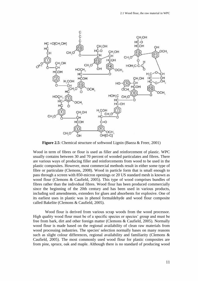
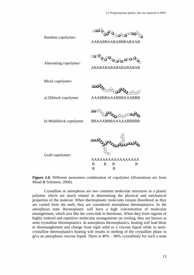
Figure 2.5: Chemical structure of softwood Lignin (Baeza & Freer, 2001) ............. 11 Figure 2.6: Different monomers combination of copolymer (illustrations are from
Moad & Solomon, 2006). ....................................................................... 13 Figure 2.7: Schematic representation of (a) fold plane showing regular chain folding,
(b) ideal stacking of lamellar crystals, (c) interlamellar amorphous
model, and (d) randomly distributed crystallites (Chanda & Roy, 2006)
................................................................................................................ 14 Figure 2.8: Isotactic polypropylene structure (Brydson, 1999). ............................... 15
Figure 2.9: Coupling agent reaction (illustration from Specialchem4polymers) ..... 17 Figure 2.10: The decomposition reactions of some peroxides ................................. 19 Figure 2.11: Grafting reaction of vinyl functional group from a silane coupling agent
to polypropylene (Nachtigall et al., 1999) ............................................. 22 Figure 2.12: Proposed bonding mechanisms in the silane cross-linked composites.
Covalent bonding between wood and PE through (1) condensation and
(2) through free radical reaction. Secondary interactions through (3)
hydrogen bonding and (4) van der Waals interaction Bengtsson et al.
(2006). .................................................................................................... 23
Figure 2.13: Alkoxysilane coupling reaction (Arkles, 2000; Arkles et al., 1992). ... 24 Figure 2.14: Reactivity of silanes and silanols (Weissenbach & Mack, 2005) ........ 25 Figure 2.15: a) α-methacryloxymethyltrimethoxy silane and ................................... 27
Figure 2.16: Grafting of maleic anhydride to polypropylene (Ghaemy & Roohina,
2003). ...................................................................................................... 28 Figure 2.17: Esterification of cellulose by MAPP (Bledzki et al., 1996). ................ 29 Figure 2.18: Coupling reaction of m-TMI grafted PP with wood fibre (Karmarkar et
al., 2007). ............................................................................................... 30 Figure 2.19: Bonding reaction of isocyanate, MAPP and wood ............................... 31 Figure 2.20: Coupling reaction of isocyanate between wood and PP or MAPP ...... 31 Figure 2.21: (a) Polydimethylsiloxane structures (b) A three-dimensional model of
polydimethylsiloxane (Kallio, 2005) ...................................................... 32
Figure 2.22: A schematic description of an interface and interphase in a cross-
section of WPC (Niska & Sanadi, 2008) ................................................ 34
ii
Figure 2.23: Schematic of three distinct failure modes; adhesive failure (I and II) and
cohesive failure (III) ............................................................................... 35 Figure 2.24: Bond formed by adsorption (illustration from SpecialChem) .............. 36 Figure 2.25: Bond formed by molecular entanglement following interdiffusion
(illustration from SpecialChem) ............................................................. 37 Figure 2.26: Bond formed by electrostatic attraction where cationic groups at the end
of molecules attracted to an anionic surface resulting in polymer
orientation at the surface (illustration from SpecialChem) .................... 38 Figure 2.27: Chemical bonding formed between substrate chemical groups and
adhesive chemical group on the other surface (illustration from
SpecialChem) ......................................................................................... 39
Figure 2.28: Mechanical interlocking formed when a liquid polymer wets a rough
solid surface (illustration from SpecialChem) ....................................... 39 Figure 2.29: A bouncing ball describing storage modulus E’ (the recovered part that
is how high it bounced) and loss modulus E” (the difference between the
height dropped from and the bounce) (Menard, 2008). ......................... 40 Figure 2.30: An idealized scan showing the effect of various molecular relaxations
on the storage modulus curve Menard (2008) ........................................ 41
Figure 2.31: Free volume in polymer (illustration from The glass transition) ......... 41 Figure 2.32: Co-rotating intermeshing twin-screw extruder (Todd, 2005). ............. 43
Figure 2.33: The different between (a) conical and (b) parallel twin-screw extruder
(Optimat & Merl, 2003) ......................................................................... 44 Figure 2.34: Dispersive and distributive morphology of compound. ....................... 46
Figure 3.1: (a) Spruce wood particle sizes 0.6 mm – 1.25 mm and (b) 1.25 mm –
3.15 mm .................................................................................................. 47 Figure 3.2: Wood flour ............................................................................................. 53 Figure 3.3: Impregnation setup ................................................................................. 53
Figure 3.4: Polypropylene (a) original pellet and (b) grain size ............................... 55 Figure 3.5: Compounding setup ................................................................................ 56 Figure 3.6: WPC pellets with (a) WF/PP 70/30 composition and with (b) WF/PP
30/70 composition .................................................................................. 57
Figure 3.7: Flour form WPC ..................................................................................... 58 Figure 3.8: WF/PP 70/30 panels with different formulations; (a) without coupling
agent (b) with 1.75% very high molecular weight bifunctional triethoxy-
vinyl PDMS (c) with 1.75% MAPP and (d) WP/PP 70/30 with particle
size of 0.6 – 1.25 mm and treated with 1.75% of 50% master batch very
high molecular weight bifunctional triethoxy-vinyl PDMS in PP. ........ 59 Figure 3.9: Specimens cutting arrangement .............................................................. 60
Figure 3.10: Overall processing procedure ............................................................... 64 Figure 4.1: FTIR spectrum of 1.75% triethoxy PDMS treated wood compared with
the untreated wood and triethoxy PDMS. .............................................. 67 Figure 4.2: FTIR spectrum of different triethoxy PDMS treatment concentration .. 68 Figure 4.3: Moisture absorption of wood flour under ambient temperature with
1.75% of different PDMS treatment in the matter of time. .................... 68 Figure 4.4: The effect of treatment amount on the flexural strength of WF/PP 70/30
with different types PDMS coupling agent ............................................ 69
iii
Figure 4.5: The effect of treatment amount on the flexural strength of WF/PP 70/30
with different bifunctional triethoxy-vinyl PDMS molecular weight .... 70 Figure 4.6: The effect of treatment amount on the modulus of elasticity of WF/PP
70/30 with different types PDMS coupling agent .................................. 71 Figure 4.7: The effect of treatment amount on the modulus of elasticity of WF/PP
70/30 with different bifunctional triethoxy-vinyl PDMS molecular
weight ..................................................................................................... 71 Figure 4.8: The effect of MAPP treatment amount on the flexural strength and
modulus of elasticity of WF/PP 70/30 ................................................... 72 Figure 4.9: The effect of the treatment amount on the flexural strength and modulus
of elasticity of WF/PP 70/30 treated with 50% master batch very high
molecular weight bifunctional triethoxy-vinyl PDMS compounded in
polypropylene. ........................................................................................ 73 Figure 5.1: The effect of 2% DCP on flexural strength of WF/PP 50/50 with
different PDMS treatment ...................................................................... 75 Figure 5.2: The effect of 2% DCP on impact strength of WF/PP 50/50 with different
PDMS treatment ..................................................................................... 75 Figure 5.3: The effect of DCP on flexural strength of WF/PP composites with
decreasing composition of PP component ............................................. 76 Figure 5.4: (a) DCP (b) cumyloxy radicals (c) acetophenone and (d) methyl radicals
................................................................................................................ 77 Figure 5.5: Tg of the loss modulus for WF/PP 70/30 with and without 0.1% DCP .. 78 Figure 5.6: The effect of DCP on modulus of elasticity of WF/PP composites with
decreasing composition of PP component ............................................. 79
Figure 5.7: The effect of DCP on impact strength of WF/PP composites with
decreasing composition of PP component ............................................. 80 Figure 5.8: The effect of DCP on flexural strength of WF/PP composites with three
different compositions ............................................................................ 80 Figure 5.9: The effect of DCP on modulus of elasticity of WF/PP composites with
three different compositions ................................................................... 81
Figure 5.10: The effect of DCP on impact strength of WF/PP composites with three
different compositions ............................................................................ 81 Figure 5.11: The effect of DCP on flexural strength of 70/30 WF/PP with and
without 1.75% very high molecular weight bifunctional triethoxy-vinyl
PDMS ..................................................................................................... 82 Figure 5.12: The effect of DCP on modules of elasticity of 70/30 WF/PP with and
without 1.75% very high molecular weight bifunctional triethoxy-vinyl
PDMS ..................................................................................................... 83
Figure 5.13: The effect of DCP on impact strength of 70/30 WF/PP with and without
1.75% very high molecular weight bifunctional triethoxy-vinyl PDMS 83 Figure 5.14: SEM micrographs of WF/PP 70/30 (a) without treatment, (b) with 1.75
very high molecular weight bifunctional triethoxy-vinyl PDMS with
0.1% DCP and (c) with 1.75 very high molecular weight bifunctional
triethoxy-vinyl PDMS without DCP ...................................................... 85 Figure 5.15: SEM micrographs of WF/PP 70/30 (a) without treatment and (b) with
1.75% very high molecular weight bifunctional triethoxy-vinyl PDMS
and 0.1% DCP ........................................................................................ 86
iv
Figure 5.16: SEM-EDX micrographs of WF/PP 70/30 with 1.75% very high
molecular weight bifunctional triethoxy-vinyl PDMS with 0.1% DCP . 87 Figure 5.17: SEM-EDX images of WF/PP 70/30 with 1.75% very high molecular
weight bifunctional triethoxy-vinyl PDMS without DCP ...................... 88 Figure 5.18: SEM-EDX of polished cross-section specimen of WF/PP 70/30 (a)
without treatment, (b) with 1.75% very high molecular weight
bifunctional triethoxy-vinyl PDMS with 0.1% DCP and (c) with 1.75%
very high molecular weight bifunctional triethoxy-vinyl PDMS with
0.1% DCP ............................................................................................... 89 Figure 5.19: Microscopic images of WF/PP 70/30 composites treated with 1.75%
very high molecular weight bifunctional triethoxy-vinyl PDMS.
Different magnification images (a) With 0.1% DCP and (b) Without
DCP. ....................................................................................................... 91 Figure 5.20: Influence of DCP on the water absorption of 70/30 WF/PP composites
treated with 1.75% very high molecular weight bifunctional triethoxy-
vinyl PDMS ............................................................................................ 92 Figure 5.21: Influence of DCP on the volume of 70/30 WF/PP composites treated
with 1.75% very high molecular weight bifunctional triethoxy-vinyl
PDMS ..................................................................................................... 92 Figure 5.22: Storage modulus and loss modulus comparison of 70/30 WF/PP
composites containing 1.75% very high molecular weight bifunctional
triethoxy-vinyl PDMS with and without 0.1% DCP. ............................. 93 Figure 5.23: Tan delta peak of WF/PP 70/30 with 1.75% very high molecular weight
bifunctional triethoxy-vinyl PDMS with 0.1% DCP at different
frequency. ............................................................................................... 94 Figure 5.24: Loss peak in the PP tan delta plot at different frequency ..................... 95 Figure 5.25: Tan delta peak comparison of WF/PP 70/30 with 1.75% very high
molecular weight bifunctional triethoxy-vinyl PDMS with and without
0.1% DCP and untreated WF/PP 70/30 without DCP at 1Hz of
frequency. ............................................................................................... 95
Figure 5.26: Arrhenius plot for 1.75% bifunctional triethoxy-vinyl PDMS treated
composites with and without DCP and untreated composite without
DCP. ....................................................................................................... 96 Figure 6.1: Flexural strength of 70/30 WF/PP treated with 1.75% PDMS containing
different functional group and functional group attachment .................. 97 Figure 6.2: Modulus of elasticity of 70/30 WF/PP treated with 1.75% PDMS
containing different functional group and functional group attachment 98 Figure 6.3: Storage modulus and loss modulus comparison of 70/30 WF/PP
composites containing 1.75% treatment of very high molecular weight
bifunctional triethoxy-vinyl PDMS and 50/50 mixture of triethoxy
PDMS/vinyl PDMS. ............................................................................... 99 Figure 6.4: Tan delta peak comparison of 70/30 WF/PP composites containing
1.75% treatment of very high molecular weight bifunctional triethoxy-
vinyl PDMS and 50/50 mixture of triethoxy PDMS/vinyl PDMS at 1Hz
of frequency. ......................................................................................... 100
v
Figure 6.5: Arrhenius plot of the tan delta peak for the comparison of 50/50 mixture
of triethoxy PDMS/vinyl PDMS and very high molecular weight
bifunctional triethoxy-vinyl PDMS. ..................................................... 100 Figure 6.6: Expected reaction mechanisms between wood and bifunctional
triethoxy-vinyl PDMS during impregnation. ....................................... 101 Figure 6.7: Expected reaction mechanisms between bifunctional triethoxy-vinyl
PDMS and PP chain during compounding. .......................................... 102 Figure 6.8: Expected C-O-C Bonding (1070 – 1150 cm
-1) from ATR-FTIR spectrum
of 1.75% very high molecular weight bifunctional triethoxy-vinyl PDMS
treated wood flour. ............................................................................... 103 Figure 6.9: Comparison of 1.75% very high molecular weight bifunctional triethoxy-
vinyl PDMS treated and untreated wood flour after 24-hour xylene
extraction. No new C-O-C bonding (1070 – 1150 cm-1
) exists; both
treated and untreated wood flour showing the same spectrum. ........... 103
Figure 6.10: Microscopic images of 70/30 WF/PP composites (a) treated with 1.75%
very high molecular weight bifunctional triethoxy-vinyl PDMS and (b)
without treatment at different magnification. ....................................... 104 Figure 6.11: Influence of bifunctional triethoxy-vinyl PDMS molecular weight on
flexural strength WF/PP 70/30 ............................................................. 106 Figure 6.12: Flexural strength of WF/PP 30/70 treated with difference molecular
weight bifunctional triethoxy-vinyl PDMS .......................................... 106 Figure 6.13: Influence of bifunctional triethoxy-vinyl PDMS molecular weight on
modulus of elasticity WF/PP 70/30 ...................................................... 107
Figure 6.14: Modulus of elasticity of WF/PP 30/70 treated with difference molecular
weight bifunctional triethoxy-vinyl PDMS .......................................... 107 Figure 6.15: Influence of bifunctional triethoxy-vinyl PDMS molecular weight on
impact strength WF/PP 70/30 .............................................................. 108
Figure 6.16: Impact strength of WF/PP 30/70 treated with difference molecular
weight bifunctional triethoxy-vinyl PDMS .......................................... 108 Figure 7.1: Flexural strength performance comparison of coupling agent with
different composition ........................................................................... 109
Figure 7.2: Modulus of elasticity performance comparison of coupling agent with
different composition ........................................................................... 110 Figure 7.3: Impact strength performance comparison of coupling agent with
different composition ........................................................................... 111 Figure 7.4: Microscopic images of 70/30 WF/PP composites (a) treated with 1.75%
very high molecular weight bifunctional triethoxy-vinyl PDMS and (b)
1.75% MAPP at different magnification. ............................................. 112
Figure 7.5: Storage modulus and loss modulus comparison of 70/30 WF/PP
composites containing 1.75% treatment of very high molecular weight
bifunctional triethoxy-vinyl PDMS and 1.75% MAPP. ....................... 113 Figure 7.6: Tan delta peak comparison of 70/30 WF/PP composites containing
1.75% very high molecular weight bifunctional triethoxy-vinyl PDMS
and 1.75% MAPP at 1Hz of frequency. ............................................... 113 Figure 7.7: Arrhenius Plot of 70/30 WF/PP composites treated with bifunctional
PDMS and MAPP ................................................................................ 114
vi
Figure 7.8: The effect of coupling agent on the water absorption of 70/30 WF/PP
composites ............................................................................................ 114 Figure 7.9: The effect of coupling agent on the volume change of 70/30 WF/PP
composites ............................................................................................ 115 Figure 7.10: The effect of coupling agent on the water absorption of 30/70 WF/PP
composites ............................................................................................ 117
Figure 7.11: The effect of coupling agent on the volume change of 30/70 WF/PP
composites ............................................................................................ 117 Figure 7.12: Pinwheel models of composites modified with a coupling agent´s
interfaces; (a) wood-polymer ratio is 50/50 (b) more polymer was used
(c) more wood was used (Lu et al., 2005). ........................................... 118
Figure 7.13: Chromatograph of sugar analysis for untreated 70/30 WF/PP composite
.............................................................................................................. 120 Figure 7.14: Chromatograph of sugar analysis for 70/30 WF/PP composite treated
with 1.75% very high molecular weight bifunctional triethoxy-vinyl
PDMS ................................................................................................... 121 Figure 7.15: (a) Three free hydroxyl group exist in every monomer in a
polysaccharide structure and (b) five free hydroxyl group exist in a
monomer structure ................................................................................ 122 Figure 8.1: The effect PDMS conditions and method of treatment application on
WF/PP composites flexural strength with different WF/PP composition.
.............................................................................................................. 124 Figure 8.2: The effect PDMS conditions and method of treatment application on
WF/PP composites modulus of elasticity with different matrix
composition .......................................................................................... 125 Figure 8.3: The effect PDMS conditions and method of treatment application on
WF/PP composites impact strength with different matrix composition126
Figure 8.4: Influence of 1.75% different conditions very high molecular weight
bifunctional triethoxy-vinyl PDMS on the water absorption of 70/30
WF/PP composites ............................................................................... 127
Figure 8.5: Influence of 1.75% different conditions very high molecular weight
bifunctional triethoxy-vinyl PDMS on the volume change of 70/30
WF/PP composites ............................................................................... 127 Figure 8.6: Influence of 1.75% different conditions very high molecular weight
bifunctional triethoxy-vinyl PDMS on the water absorption of 30/70
WF/PP composites ............................................................................... 128
Figure 8.7: Influence of 1.75% different conditions very high molecular weight
bifunctional triethoxy-vinyl PDMS on the volume change of 30/70
WF/PP composites ............................................................................... 128 Figure 8.8: Influence of 1.75% different conditions very high molecular weight
bifunctional triethoxy-vinyl PDMS on the water absorption of 50/50
WF/PP composites ............................................................................... 129 Figure 8.9: Influence of 1.75% different conditions very high molecular weight
bifunctional triethoxy-vinyl PDMS on the volume change of 50/50
WF/PP composites ............................................................................... 129 Figure 8.10: Storage modulus and loss modulus comparison of 70/30 WF/PP
composites treated with different bifunctional PDMS conditions ....... 130
vii
Figure 8.11: Tan delta peak comparison of 70/30 WF/PP composites treated with
different PDMS conditions at 1Hz of frequency .................................. 131 Figure 8.12: Arrhenius plot of 70/30 WF/PP treated with different PDMS conditions
.............................................................................................................. 131 Figure 8.13: Microscopic images of 70/30 WF/PP composites treated with different
treatment conditions of 1.75% very high molecular weight bifunctional
triethoxy-vinyl PDMS: (a) 100% purity liquid, impregnated, (b) 50%
master batch PP, in situ compounded, (c) 50% emulsion, sprayed and (d)
untreated. .............................................................................................. 132 Figure 8.14: Microscopic images of 30/70 WF/PP composites treated with different
treatment conditions of 1.75% very high molecular weight bifunctional
triethoxy-vinyl PDMS: (a) 100% purity liquid, impregnated, (b) 50%
master batch PP, in situ compounded, (c) 50% emulsion, sprayed and (d)
untreated. .............................................................................................. 133
Figure 9.1: Different particle size of wood ............................................................. 134 Figure 9.2: Influence of wood particle size on 70/30 WF/PP flexural strength with
different coupling agent ....................................................................... 135 Figure 9.3: Influence of wood particle size on 70/30 WF/PP modulus of elasticity
with different coupling agent ............................................................... 135 Figure 9.4: Influence of wood particle size on 70/30 WF/PP impact strength with
different coupling agent ....................................................................... 136 Figure 9.5: Influence of wood particle size on 30/70 WF/PP flexural strength with
different coupling agent ....................................................................... 136
Figure 9.6: Influence of wood particle size on 30/70 WF/PP modulus of elasticity
with different coupling agent ............................................................... 137 Figure 9.7: Influence of wood particle size on 30/70 WF/PP impact strength with
different coupling agent ....................................................................... 137
Figure 9.8: WF/PP 70/30 panels with 1.75% very high molecular weight
bifunctional triethoxy-vinyl PDMS (a) with particle size of 0.3 – 0.5 mm
and (b) with particle size of 0.6 – 1.25 mm .......................................... 139
Figure 9.9: Water absorption of 70/30 WF/PP with or without 1.75% MAPP or very
high molecular weight bifunctional triethoxy-vinyl PDMS (Bif PDMS)
coupling agent in the composites containing different particle size of
wood. .................................................................................................... 139 Figure 9.10: Volume change of 70/30 WF/PP with or without 1.75% MAPP or very
high molecular weight bifunctional triethoxy-vinyl PDMS (Bif PDMS)
coupling agent in the composites containing different particle size of
wood. .................................................................................................... 140
Figure 9.11: The effect of re-compounding of the treated composites with different
composition to the flexural strength ..................................................... 141 Figure 9.12: The effect of re-compounding of the treated composites with different
composition to the modulus of elasticity .............................................. 142 Figure 9.13: The effect of re-compounding of the treated composites with different
composition to the impact strength ...................................................... 143 Figure 9.14: The effect of re-compounding of the 70/30 WF/PP composites with
different treatments on the water absorption. ....................................... 143

viii
Figure 9.15: The effect of re-compounding of the 70/30 WF/PP composites with
different treatments on the volume change. ......................................... 144 Figure 9.16: The effect of re-compounding of the 30/70 WF/PP composites with
different treatments on the water absorption. ....................................... 144 Figure 9.17: The effect of re-compounding of the 30/70 WF/PP composites with
different treatments on the volume change. ......................................... 145
Figure 9.18: The effect of MAPP pre-mixing to the flexural strength of composites
with different compositions .................................................................. 146 Figure 9.19: The effect of MAPP pre-mixing to the modulus of elasticity of
composites with different compositions ............................................... 146 Figure 9.20: The effect of MAPP pre-mixing to the impact strength of composites
with different composition ................................................................... 147
Figure 9.21: The effect of 1.75% MAPP pre-mixing to the water absorption of 70/30
WF/PP composites. .............................................................................. 148
Figure 9.22: The effect of 1.75% MAPP pre-mixing to the volume change of 70/30
WF/PP composites. .............................................................................. 148 Figure 9.23: The effect of 1.75% MAPP pre-mixing to the water absorption of 30/70
WF/PP composites ............................................................................... 149
Figure 9.24: The effect of 1.75% MAPP pre-mixing to the volume change of 30/70
WF/PP composites ............................................................................... 149
ix
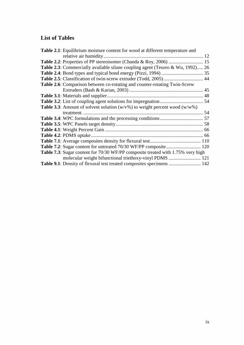
List of Tables
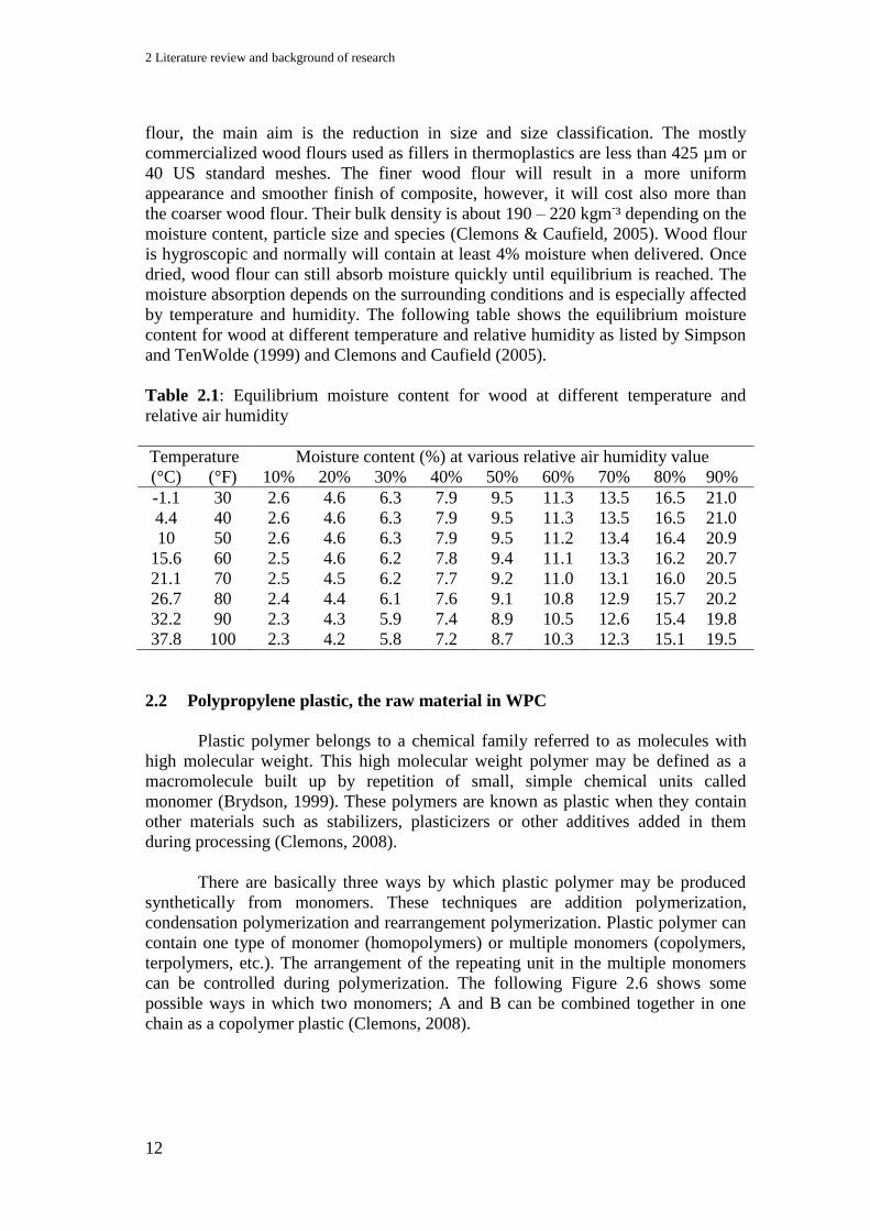
Table 2.1: Equilibrium moisture content for wood at different temperature and
relative air humidity ................................................................................. 12 Table 2.2: Properties of PP stereoisomer (Chanda & Roy, 2006) ............................ 15 Table 2.3: Commercially available silane coupling agent (Tesoro & Wu, 1992). .... 26
Table 2.4: Bond types and typical bond energy (Pizzi, 1994) .................................. 35 Table 2.5: Classification of twin-screw extruder (Todd, 2005) ................................ 44 Table 2.6: Comparison between co-rotating and counter-rotating Twin-Screw
Extruders (Bash & Karian, 2003) ............................................................ 45 Table 3.1: Materials and supplier .............................................................................. 48
Table 3.2: List of coupling agent solutions for impregnation ................................... 54
Table 3.3: Amount of solvent solution (w/v%) to weight percent wood (w/w%)
treatment. ................................................................................................. 54
Table 3.4: WPC formulations and the processing conditions ................................... 57 Table 3.5: WPC Panels target density ....................................................................... 58 Table 4.1: Weight Percent Gain ................................................................................ 66
Table 4.2: PDMS uptake ........................................................................................... 66 Table 7.1: Average composites density for flexural test ......................................... 110 Table 7.2: Sugar content for untreated 70/30 WF/PP composite ............................ 120
Table 7.3: Sugar content for 70/30 WF/PP composite treated with 1.75% very high
molecular weight bifunctional triethoxy-vinyl PDMS .......................... 121
Table 9.1: Density of flexural test treated composites specimens .......................... 142
x
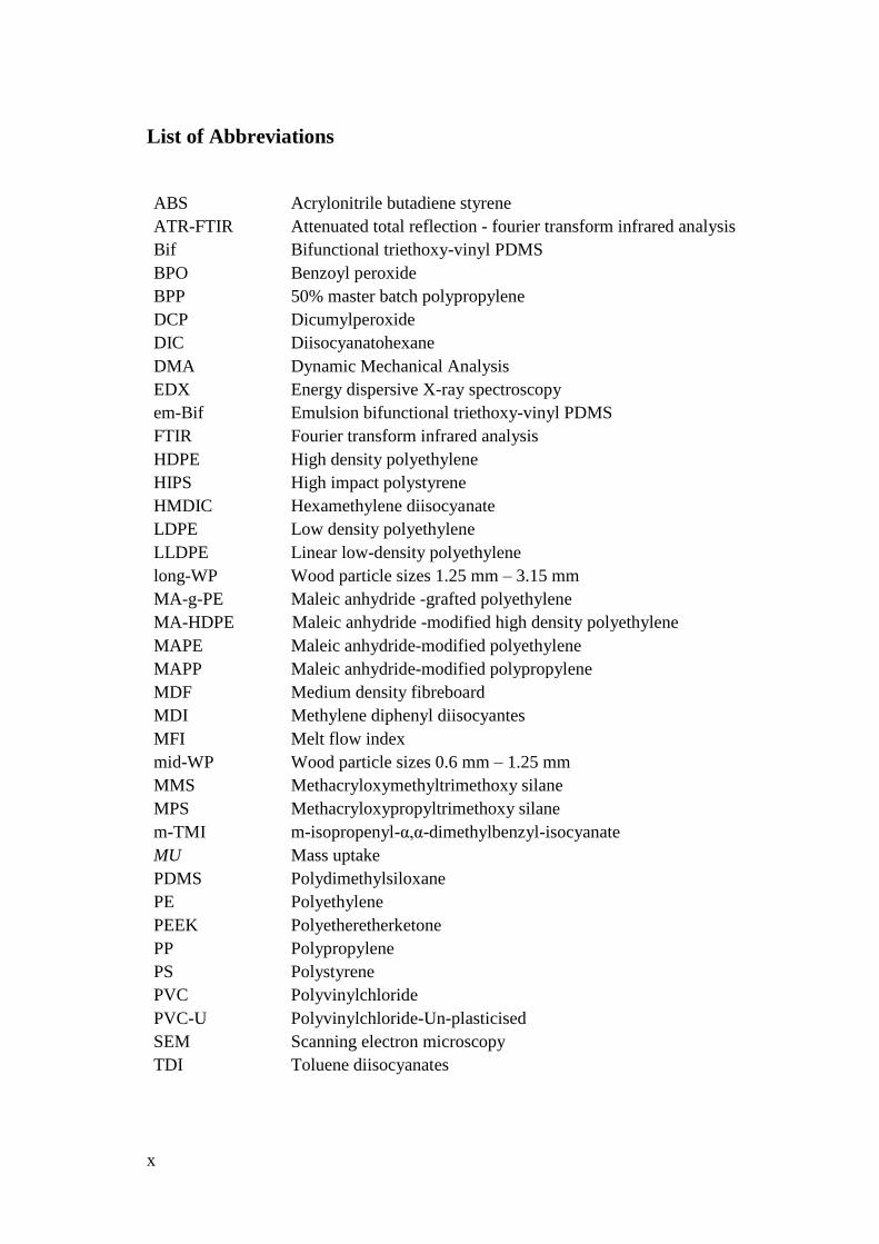
List of Abbreviations
ABS Acrylonitrile butadiene styrene
ATR-FTIR Attenuated total reflection - fourier transform infrared analysis
Bif Bifunctional triethoxy-vinyl PDMS
BPO Benzoyl peroxide
BPP 50% master batch polypropylene
DCP Dicumylperoxide
DIC Diisocyanatohexane
DMA Dynamic Mechanical Analysis
EDX Energy dispersive X-ray spectroscopy
em-Bif Emulsion bifunctional triethoxy-vinyl PDMS
FTIR Fourier transform infrared analysis
HDPE High density polyethylene
HIPS High impact polystyrene
HMDIC Hexamethylene diisocyanate
LDPE Low density polyethylene
LLDPE Linear low-density polyethylene
long-WP Wood particle sizes 1.25 mm – 3.15 mm
MA-g-PE Maleic anhydride -grafted polyethylene
MA-HDPE Maleic anhydride -modified high density polyethylene
MAPE Maleic anhydride-modified polyethylene
MAPP Maleic anhydride-modified polypropylene
MDF Medium density fibreboard
MDI Methylene diphenyl diisocyantes
MFI Melt flow index
mid-WP Wood particle sizes 0.6 mm – 1.25 mm
MMS Methacryloxymethyltrimethoxy silane
MPS Methacryloxypropyltrimethoxy silane
m-TMI m-isopropenyl-α,α-dimethylbenzyl-isocyanate
MU Mass uptake
PDMS Polydimethylsiloxane
PE Polyethylene
PEEK Polyetheretherketone
PP Polypropylene
PS Polystyrene
PVC Polyvinylchloride
PVC-U Polyvinylchloride-Un-plasticised
SEM Scanning electron microscopy
TDI Toluene diisocyanates
xi
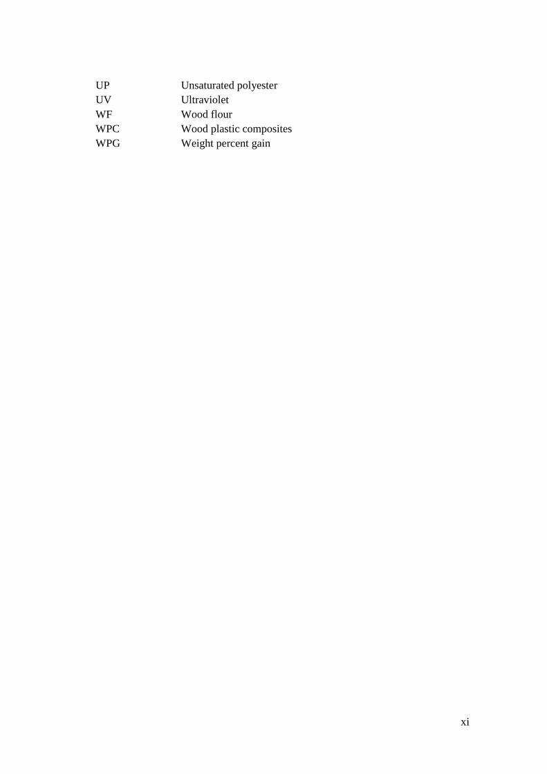
UP Unsaturated polyester
UV Ultraviolet
WF Wood flour
WPC Wood plastic composites
WPG Weight percent gain
xii
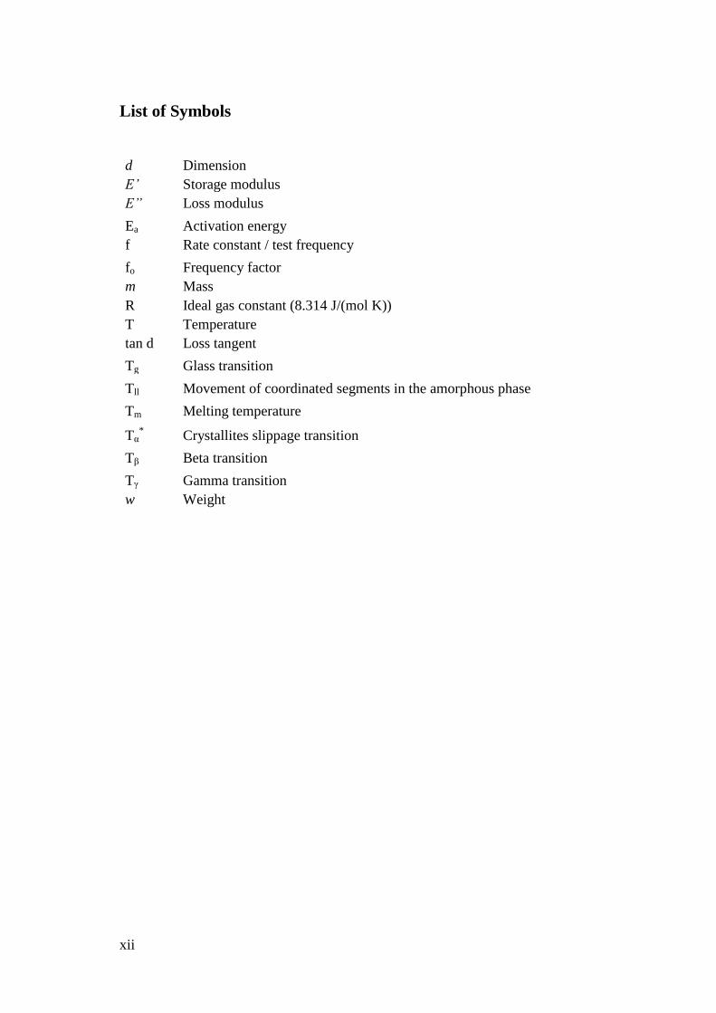
List of Symbols
d Dimension
E’ Storage modulus
E” Loss modulus
Ea Activation energy
f Rate constant / test frequency
fo Frequency factor
m Mass
R Ideal gas constant (8.314 J/(mol K))
T Temperature
tan d Loss tangent
Tg Glass transition
Tll Movement of coordinated segments in the amorphous phase
Tm Melting temperature
Tα* Crystallites slippage transition
Tβ Beta transition
Tγ Gamma transition
w Weight

1
1 Introduction
Composites are the most advanced and adaptable engineering materials
known to man. They are defined as materials made of two or more components and
consist of two or more phases that can still be distinguished when examined under
optical or electron microscopes (Nielson & Landel, 1994). Actually, we have been
using different types of composite materials in our daily lives without realizing them.
These materials can be easily found around us. They normally occur naturally such
as many tissues in the body, which made up of stiff fibres such as collagen embedded
in a lower stiffness matrix. The material, in which the fibres are embedded, is called
the matrix, while the fibres are called the reinforcement. Teeth, plant leaves and bird
feathers are also the examples of natural composites. On the other hand, there is as
well a wide variety of man-made composites constructed of plastic matrices with
organic, inorganic or natural fibres, metal matrices with metal fibres, ceramic
matrices with metal or ceramic fibres and so on. Shower stalls and bathtubs made of
fibre glass, carbon or epoxy bicycle, and graphite tennis or badminton racket are
examples of the products from man-made composites. Those composite materials
can be classified in many ways depending on the ideas and concepts to be identified.
According to Hull (1995) composite materials can be classified as follows:
Natural composites for materials such as wood, bone, bamboo, muscle and
other tissues.
Microcomposites for materials such as metallic alloys, for example, steels
and also materials such as toughened thermoplastic, for examples, high
impact polystyrene (HIPS) and acrylonitrile butadiene styrene (ABS).
Macrocomposites for engineering products such as galvanized steel and
reinforced concrete beams.
Microcomposites as referred to Nielson & Landel (1994) can be divided into three
general classes that are:
Particulate-filled composites consisting of a continuous matrix phase and
discontinuous filler phase made up of discrete particles. Examples of this type
are wood particles and silica or clay filled plastic polymer composites.
Fibre-filled composites consisting also a continuous matrix phase embedded
with short or long fibres reinforcement as the discontinuous phase. Glass,
carbon fibre or Kevlar reinforced plastic polymer are example of this type.
Skeletal or interpenetrating network composites consisting of two continuous
phases. This type includes filled open-cell foams and sintered mats or meshes
filled with some material.

1 Introduction
2
Composites can be processed by mixing the separate materials. The
dispersion of one material in the other can be done in a controlled way to achieve
optimum properties. The ability in processing composites makes them useful and
better than their constituent materials. Their utilities often combine the attributes of
their individual component. The properties are normally superior or unique in some
specific aspect related to the properties of the constituent components (Hull, 1995).
They can be tailored for various reasons such as better stiffness, higher materials
strength, better dimensional stability, better impact or toughness, higher heat
distortion temperature, better mechanical damping, lower gases or liquids
permeability, weight reduction, electrical properties or cost reduction.
A simple example of producing composite material is when a metal with high
conductivity and a plastic that is electrically insulating are combined in alternating
layers in a laminate. A highly anisotropic composite that has the conducting
properties of the metal in directions parallel to the layers and the insulating properties
of the plastic normal to the layers is obtained (Milton, 2004). Another example is
wood that is strong in the fibre direction, but the fibres pull apart easily. By
alternating layers of wood that are strong perpendicular to each other, plywood that
is strong in two plane directions is obtained (Milton, 2004).
1.1 Wood Plastic Composites (WPC)
Wood plastic composites (WPC) are generally composite materials made of
wood based fibres or flour and a plastic polymer. They cover a wide range of
composite materials that use plastics such as polypropylene, polyethylene,
polystyrene, polyvinylchloride and so on for the matrix phase and fillers ranging
from the wood flour to natural fibres. Though both wood and plastics are polymer
based, they are very different in origin, structure and performance. The plastic matrix
will form continuous phase surrounding the wood component (Clemons, 2008). The
WPC will consist of both wood and plastic features. These products are applied in
various sectors, including automotive, building and furniture or household articles
(Danyadi et al., 2007). WPCs have many benefits and are also environmentally
friendly because:
Residual wood (e.g. sawdust) and recycled plastic could be used beside the
virgin wood flour or fibres and plastic polymer.
Potentially recyclable since it can be reground and reprocessed.
Most of WPCs are considered non-hazardous waste and can be disposed by
standard methods.
Using waste wood products to produce WPC will save the cost of disposal
while recycling plastics is also profitable and ethical. The plastic can be from
recycled plastic bags or battery case materials, although in demanding applications
new plastic materials are required. Producing WPC requires plentiful of raw
materials, turning the wood waste and recycled plastic to assets instead of liabilities.
WPCs are competitively priced and are competitive with traditional materials such as

1.1 Wood Plastic Composites (WPC)
3
timber, MDF and PVC-U (Tangram, 2002). They are easily produced and fabricated
by standard processing procedures and are available in a broad range of finishes and
appearances. They can be extruded or injection moulded which maximizes resource
efficiency and allows design flexibility for improved fastening, stiffening and
reinforcement, finishing and joining. These wooden products need no further
processing while weather and water resistance make them ideal for outdoor
applications where untreated timber products are unsuitable (Kent, 2005). The
following figures show some of the products made with WPC.
(a) (b)
(c) (d)
Figure 1.1: Some products made with WPC (a) fencing (b) decking (c) kid
playhouse (d) furniture
Combination of wood and thermoplastics results in materials with unique
physical properties. In general, the wood component tends to increase the stiffness,
thermal stability, UV resistance and workability of the composite. The
thermoplastics otherwise improve moisture resistance, resistance to biological decay
and impart thermoforming characteristic (Wolcott, 2001). Though their stiffness and
strength still lay between both materials the density is generally higher than either.
Their properties come directly from their structure; at low filler content, they are
intimate mixes of wood particles and plastic. The plastic effectively coats the wood
particle as a thin layer (Tangram, 2002). Their properties and characteristics lay more
to plastic. Otherwise at higher filler content up to 70% of wood, results in products
those are normally stiffer and emulate the characteristic and properties of wood.

1 Introduction
4
Wood and natural fibres offer more advantages over conventional
reinforcement materials in plastics. From a polymer composite standpoint, wood is
less expensive, stiffer, and stronger than many commodity synthetic polymers,
making it a candidate for filling or reinforcing them (Clemons 2000). It is also
lighter, less abrasive, renewable and readily available. Its specific properties are
comparable to those of other conventional materials used (Saheb & Jog 1999;
Clemons 2000). The advantages of WPC have been touted by the researches for a
long time. However, these materials were only commercialized and become the
cutting edge in the area of building, construction and furniture about two decades ago
and as well expanded to the automotive application recently (Niska & Sain, 2008).
The most common reason for the historically low use of WPC is perhaps the
unfamiliarity of the new materials in the past, which are very different from the both
main constituents polymer in characteristics, structure and performance. Even though
the WPC or natural fibre plastic composites consist of both lignocellulosic and
plastic material, their characteristics represent neither cellulose nor plastic properties.
It took time for both wood and plastic industries to take action of the advantages of
the new materials because they knew little about each other. They have few material
and equipment suppliers in common and often process materials very differently and
on different scales (Clemons, 2000). However, with the improvements in
manufacturing processes, equipment design, developments of new analytical and
testing methods and growth in process formulation and product design the uses of
wood and natural fibre in composite has caught much more intensions in both
industries and could potentially replace inorganic fillers as reinforcement in
thermoplastic (Niska & Sain 2008; Clemons 2000). Furthermore, the concern and
critical discussions on preservation of natural resources and recycling in the late 90’s
has raised the awareness and changes the interest to natural material with the focus
on renewable raw materials and enlarged the focus of research and investigations of
wood and natural fibre composites (Bledzki & Gassan 1999).
As explained earlier, the main constituents in WPC are both polymer-based
materials yet they are very different in origin, structure and performance. Wood
contains polymers such as lignin, cellulose and hemi celluloses those are strongly
polar materials and hydrophilic in nature, whereas plastics are very high molecular
weight materials whose performance are determined by its molecular structures and
are non-polar and hydrophobic in nature (Clemons, 2008; Bledzki & Gassan, 1999;
Saheb & Jog, 1999). These contradict characteristics give drawbacks, which are the
incompatibility problems in combining these materials and the tendency to form
aggregates. Thus the incompatibility of wood and plastic also comes from the very
weak interfacial interactions between both components because of the small surface
free energy of wood filler compared to the plastic polymer.
The compatibility and homogeneity of wood-plastic components are very
well known to be a challenge in producing high-quality wood polymer composites
(WPC). This is because the properties of composite materials are strongly
determined by the interaction of individual constituents (Hull, 1995). A good surface
interaction is very prominent in producing a high quality composite material. In the

1.2 Motivation for research
5
case of WPCs, the mechanical properties of the wood component are not only
dependent on the fibre or particle properties, but also to the level of adhesion
between the wood fibres or particles and the plastic matrix. The interphase formed
from the surface adhesion plays an important role in the stress transfer from the
matrix to wood particle that contributes toward the performance of the composite.
Mixing and coupling the two constituent components have always been the
most interesting subject of investigation in the composite world. Although a lot of
research and investigations have been done thoroughly for decades, new findings in
improving the performance and characteristic of the WPC are needed to widen the
application. On top of that, the uses of WPC are currently so fast developing and
expanding in various areas and becoming a very important base material in wood and
plastic industry. The increasing demand of WPC industry has been projected to rise
from 2009 through 2014 especially in automotive and building materials such as
decking, fencing, door and window (LeGault, 2009; Goldsberry, 2009; Carus, 2011).
Good adhesion and interaction between both components in producing WPC is
essential to achieve good product properties. This is a special problem in WPC
production with hydrophobic matrix polymer and hydrophilic wood particle.
Adhesion and interaction must be improved to manufacture products of high-quality
applications.
1.2 Motivation for research
The problem in combining the two incompatible components, which have
opposite polarities or different hydrophilic-hydrophobicity characteristics is the
biggest issue we are dealing with, in order to achieve a remarkable performance of
WPC. Investigations with silanes have been proven to work well in coupling the
wood and plastic to perform better. Silane coupling agents contain three alkoxy
functional groups for coupling with the wood. However, before the coupling reaction
takes place, the alkoxy silane will need to go through a hydrolysis and condensation
process that requires certain condition and time to occur. Using a specially
synthesized bifunctional polydimethylsiloxane (PDMS) coupling agent is expected to
instantly bridge the interface of both components in the composite and improve the
interphase.
1.3 Research Objectives
The main objective of this doctoral thesis is to enhance the performance of
the WPC containing 70% wood and 30% polypropylene plastic (by weight) (70/30
WF/PP) by creating better interphase bonding between the incompatible cellulose
and PP surfaces. In accomplishing this goal, the following specific objectives were
addressed:
1 Introduction
6
To modify and treat the wood flour using PDMS containing vinyl or/and
triethoxy group(s) as a single functional PDMS or as a bifunctional PDMS
coupling agent.
To determine the influence of different coupling agent conditions, that is, the
functional group, molecular weight, the materials state and methods of
application in producing composite on the WPC performance.
To investigate the interfacial interaction between wood and plastic matrices
under the influence of bifunctional triethoxy-vinyl PDMS coupling agent.
To evaluate the performance of bifunctional PDMS treated WPC with the
influence of wood particle size, wood-matrix compositions and re-
compounding process.
To characterize the mechanical properties of WPC coupled with bifunctional
PDMS by the comparison with maleic anhydride-modified PP (MAPP) coupled
composite.
1.4 Significance of the study
The findings obtained from this thesis will help to a better understanding of
the roles played by PDMS at the interface. It should increase the choice of coupling
agent and wider the field of WPC application as well.
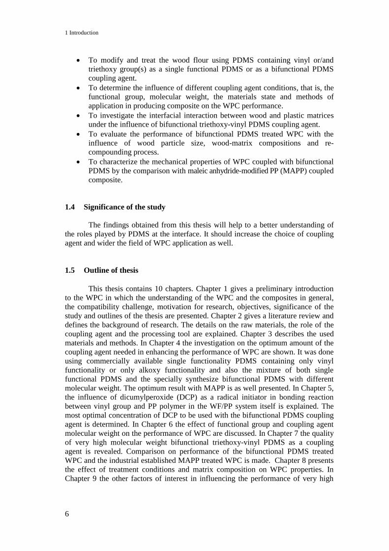
1.5 Outline of thesis
This thesis contains 10 chapters. Chapter 1 gives a preliminary introduction
to the WPC in which the understanding of the WPC and the composites in general,
the compatibility challenge, motivation for research, objectives, significance of the
study and outlines of the thesis are presented. Chapter 2 gives a literature review and
defines the background of research. The details on the raw materials, the role of the
coupling agent and the processing tool are explained. Chapter 3 describes the used
materials and methods. In Chapter 4 the investigation on the optimum amount of the
coupling agent needed in enhancing the performance of WPC are shown. It was done
using commercially available single functionality PDMS containing only vinyl
functionality or only alkoxy functionality and also the mixture of both single
functional PDMS and the specially synthesize bifunctional PDMS with different
molecular weight. The optimum result with MAPP is as well presented. In Chapter 5,
the influence of dicumylperoxide (DCP) as a radical initiator in bonding reaction
between vinyl group and PP polymer in the WF/PP system itself is explained. The
most optimal concentration of DCP to be used with the bifunctional PDMS coupling
agent is determined. In Chapter 6 the effect of functional group and coupling agent
molecular weight on the performance of WPC are discussed. In Chapter 7 the quality
of very high molecular weight bifunctional triethoxy-vinyl PDMS as a coupling
agent is revealed. Comparison on performance of the bifunctional PDMS treated
WPC and the industrial established MAPP treated WPC is made. Chapter 8 presents
the effect of treatment conditions and matrix composition on WPC properties. In
Chapter 9 the other factors of interest in influencing the performance of very high

1.5 Outline of thesis
7
molecular weight bifunctional triethoxy-vinyl PDMS and MAPP treated WF/PP
composite are evaluated. Chapter 10 is reviewing the results of the aforementioned
studies with the optimum formulation, treatment conditions and the best performance
as well as suggestions for future work.
8
2 Literature review and background of research
The unique characteristic of WPC comes from the two main constituents'
components that are wood and plastic, while the compatibility and adhesion
contributed by the coupling agent used. To gain better understanding on the
properties of WPC, it is an advantage to know the basic structure of the individual
component and the theoretical aspects of interaction that might have occurred during
processing and production of the WPC.
2.1 Wood flour, the raw material in WPC
Wood physically composes of hollow, elongate, spindle-shaped cells called
tracheids or fibres that are arranged parallel to each other along the trunk of a tree
(Miller, 1999; Clemons, 2008). These cells form the structural elements of wood
tissue. They are various in sizes and shapes and are quite firmly cemented together.
The characteristics of these fibrous cells and their arrangement affect the properties
such as strength and shrinkage as well as the grain pattern of the wood (Miller, 1999;
Clemons, 2008).
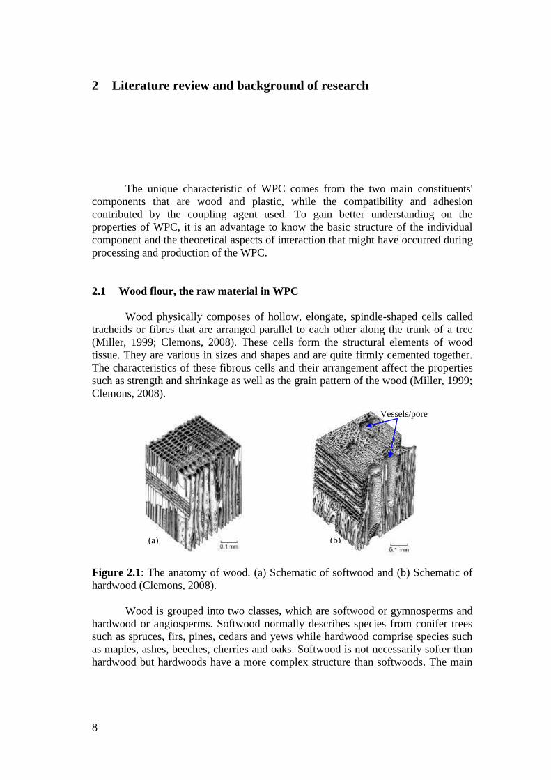
Figure 2.1: The anatomy of wood. (a) Schematic of softwood and (b) Schematic of
hardwood (Clemons, 2008).
Wood is grouped into two classes, which are softwood or gymnosperms and
hardwood or angiosperms. Softwood normally describes species from conifer trees
such as spruces, firs, pines, cedars and yews while hardwood comprise species such
as maples, ashes, beeches, cherries and oaks. Softwood is not necessarily softer than
hardwood but hardwoods have a more complex structure than softwoods. The main
Vessels/pore
s
(b) (a)
2.1 Wood flour, the raw material in WPC
9
difference between them is the presence of pores or vessels in the hardwood that is a
kind of cell with a relatively large diameter (Sjöström, 1981; Miller, 1999). These
cells form the main conduits in the movement of sap. Softwoods do not contain
vessels for conducting sap longitudinally in the tree; this function is performed by the
tracheids (Miller, 1999). Figure 2.1 shows the different anatomy of hard and
softwood (Clemons, 2008). The length of wood fibres for both wood types is also
different. Normally, the fibre length of hardwood is in the average of 1 mm. For
softwood a value in the range of 3-8 mm is typical and their fibre diameters are
typically 15-45 µm.
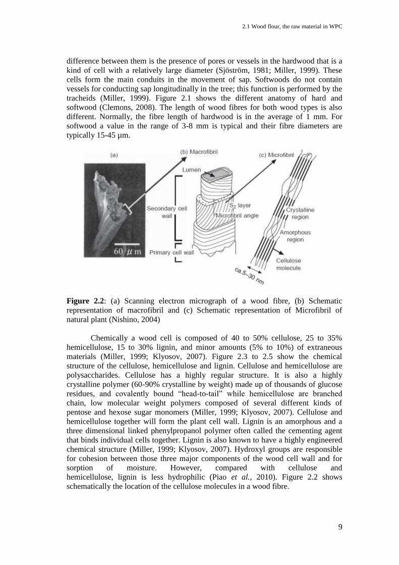
Figure 2.2: (a) Scanning electron micrograph of a wood fibre, (b) Schematic
representation of macrofibril and (c) Schematic representation of Microfibril of
natural plant (Nishino, 2004)
Chemically a wood cell is composed of 40 to 50% cellulose, 25 to 35%
hemicellulose, 15 to 30% lignin, and minor amounts (5% to 10%) of extraneous
materials (Miller, 1999; Klyosov, 2007). Figure 2.3 to 2.5 show the chemical
structure of the cellulose, hemicellulose and lignin. Cellulose and hemicellulose are
polysaccharides. Cellulose has a highly regular structure. It is also a highly
crystalline polymer (60-90% crystalline by weight) made up of thousands of glucose
residues, and covalently bound “head-to-tail” while hemicellulose are branched
chain, low molecular weight polymers composed of several different kinds of
pentose and hexose sugar monomers (Miller, 1999; Klyosov, 2007). Cellulose and
hemicellulose together will form the plant cell wall. Lignin is an amorphous and a
three dimensional linked phenylpropanol polymer often called the cementing agent
that binds individual cells together. Lignin is also known to have a highly engineered
chemical structure (Miller, 1999; Klyosov, 2007). Hydroxyl groups are responsible
for cohesion between those three major components of the wood cell wall and for
sorption of moisture. However, compared with cellulose and
hemicellulose, lignin is less hydrophilic (Piao et al., 2010). Figure 2.2 shows
schematically the location of the cellulose molecules in a wood fibre.
2 Literature review and background of research
10
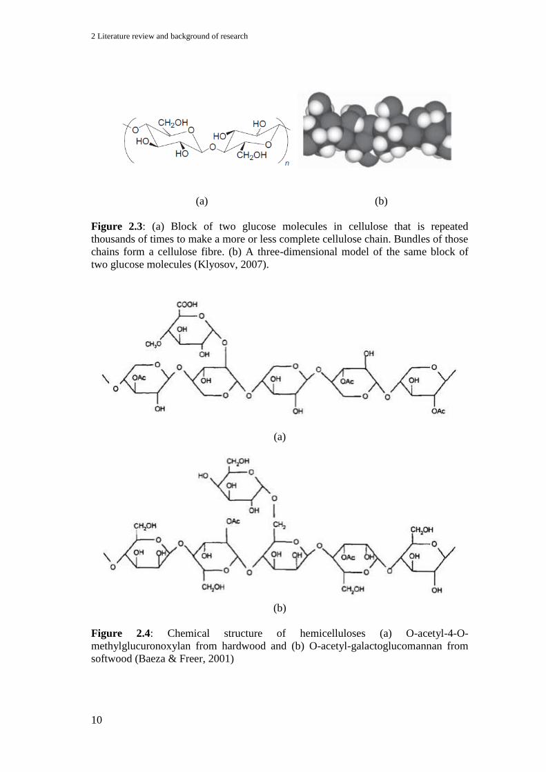
(a) (b)
Figure 2.3: (a) Block of two glucose molecules in cellulose that is repeated
thousands of times to make a more or less complete cellulose chain. Bundles of those
chains form a cellulose fibre. (b) A three-dimensional model of the same block of
two glucose molecules (Klyosov, 2007).
(a)
(b)
Figure 2.4: Chemical structure of hemicelluloses (a) O-acetyl-4-O-
methylglucuronoxylan from hardwood and (b) O-acetyl-galactoglucomannan from
softwood (Baeza & Freer, 2001)
2.1 Wood flour, the raw material in WPC
11
Figure 2.5: Chemical structure of softwood Lignin (Baeza & Freer, 2001)
Wood in term of fibres or flour is used as filler and reinforcement of plastic. WPC
usually contains between 30 and 70 percent of wooded particulates and fibres. There
are various ways of producing filler and reinforcements from wood to be used in the
plastic composites. However, most commercial methods result in either some type of
fibre or particulate (Clemons, 2008). Wood in particle form that is small enough to
pass through a screen with 850-micron openings or 20 US standard mesh is known as
wood flour (Clemons & Caufield, 2005). This type of wood comprises bundles of
fibres rather than the individual fibres. Wood flour has been produced commercially
since the beginning of the 20th century and has been used in various products,
including soil amendments, extenders for glues and absorbents for explosive. One of
its earliest uses in plastic was in phenol formaldehyde and wood flour composite
called Bakelite (Clemons & Caufield, 2005).
Wood flour is derived from various scrap woods from the wood processor.
High quality wood flour must be of a specific species or species’ group and must be
free from bark, dirt and other foreign matter (Clemons & Caufield, 2005). Normally
wood flour is made based on the regional availability of clean raw materials from
wood processing industries. The species' selection normally bases on many reasons
such as slight colour differences, regional availability and familiarity (Clemons &
Caufield, 2005). The most commonly used wood flour for plastic composites are
from pine, spruce, oak and maple. Although there is no standard of producing wood
2 Literature review and background of research
12
flour, the main aim is the reduction in size and size classification. The mostly
commercialized wood flours used as fillers in thermoplastics are less than 425 µm or
40 US standard meshes. The finer wood flour will result in a more uniform
appearance and smoother finish of composite, however, it will cost also more than
the coarser wood flour. Their bulk density is about 190 – 220 kgm-³ depending on the
moisture content, particle size and species (Clemons & Caufield, 2005). Wood flour
is hygroscopic and normally will contain at least 4% moisture when delivered. Once
dried, wood flour can still absorb moisture quickly until equilibrium is reached. The
moisture absorption depends on the surrounding conditions and is especially affected
by temperature and humidity. The following table shows the equilibrium moisture
content for wood at different temperature and relative humidity as listed by Simpson
and TenWolde (1999) and Clemons and Caufield (2005).
Table 2.1: Equilibrium moisture content for wood at different temperature and
relative air humidity
Temperature Moisture content (%) at various relative air humidity value
(°C) (°F) 10% 20% 30% 40% 50% 60% 70% 80% 90%
-1.1 30 2.6 4.6 6.3 7.9 9.5 11.3 13.5 16.5 21.0
4.4 40 2.6 4.6 6.3 7.9 9.5 11.3 13.5 16.5 21.0
10 50 2.6 4.6 6.3 7.9 9.5 11.2 13.4 16.4 20.9
15.6 60 2.5 4.6 6.2 7.8 9.4 11.1 13.3 16.2 20.7
21.1 70 2.5 4.5 6.2 7.7 9.2 11.0 13.1 16.0 20.5
26.7 80 2.4 4.4 6.1 7.6 9.1 10.8 12.9 15.7 20.2
32.2 90 2.3 4.3 5.9 7.4 8.9 10.5 12.6 15.4 19.8
37.8 100 2.3 4.2 5.8 7.2 8.7 10.3 12.3 15.1 19.5
2.2 Polypropylene plastic, the raw material in WPC
Plastic polymer belongs to a chemical family referred to as molecules with
high molecular weight. This high molecular weight polymer may be defined as a
macromolecule built up by repetition of small, simple chemical units called
monomer (Brydson, 1999). These polymers are known as plastic when they contain
other materials such as stabilizers, plasticizers or other additives added in them
during processing (Clemons, 2008).
There are basically three ways by which plastic polymer may be produced
synthetically from monomers. These techniques are addition polymerization,
condensation polymerization and rearrangement polymerization. Plastic polymer can
contain one type of monomer (homopolymers) or multiple monomers (copolymers,
terpolymers, etc.). The arrangement of the repeating unit in the multiple monomers
can be controlled during polymerization. The following Figure 2.6 shows some
possible ways in which two monomers; A and B can be combined together in one
chain as a copolymer plastic (Clemons, 2008).
2.2 Polypropylene plastic, the raw material in WPC
13
Random copolymer:
AABABBAABABBBABAAB
Alternating copolymer:
ABABABABABABABABAB
Block copolymer:
a) Diblock copolymer AAABBBAAABBBAAABBB
b) Multiblock copolymer BBAAABBBAAAAABBBBB
Graft copolymer:
AAAAAAAAAAAAAAAAA
B B B B
B B
Figure 2.6: Different monomers combination of copolymer (illustrations are from
Moad & Solomon, 2006).
Crystalline or amorphous are two common molecular structures in a plastic
polymer which are much related in determining the physical and mechanical
properties of the material. When thermoplastic molecules remain disordered as they
are cooled from the melt, they are considered amorphous thermoplastics. In the
amorphous state thermoplastic will have a high concentration of molecular
entanglement, which acts like the cross-link in thermoset. When they form regions of
highly ordered and repetitive molecular arrangements on cooling, they are known as
semi crystalline thermoplastics. In amorphous thermoplastics, heating will lead them
to disentanglement and change from rigid solid to a viscous liquid while in semi-
crystalline thermoplastics heating will results in melting of the crystalline phase to
give an amorphous viscous liquid. There is 40% – 80% crystallinity for such a semi

2 Literature review and background of research
14
crystalline thermoplastic. The most commonly used thermoplastics are polyethylene
(PE), polypropylene (PP) and polyetheretherketone (PEEK) which are semi-
crystalline. Polyvinylchloride (PVC) and polystyrene (PS) are commonly used
thermoplastics as well but amorphous. (Hull, 1995; Brydson, 1999). Figure 2.7
shows the schematic representation of the chain folding in crystalline and amorphous
part of polymer.
Figure 2.7: Schematic representation of (a) fold plane showing regular chain folding,
(b) ideal stacking of lamellar crystals, (c) interlamellar amorphous model, and (d)
randomly distributed crystallites (Chanda & Roy, 2006)
Polypropylene (PP) is a thermoplastic polymer, based on the propene
monomer (C3H6). It is produced by the chemical industry and it is used in a wide
variety of applications, such as packaging, textiles (e.g., ropes and carpets),
stationery, plastic parts and reusable containers of various types, laboratory
equipment, automotive components and other. The special characteristics of PP are:
High hardness, stiffness, and strength among the polyolefins
Relatively high dimensional stability under heat
Low toughness at low temperatures up to approx. 0 °C
High chemical and corrosion resistance
Very low water absorption
Easily machined and cut
Easy to maintain and clean
Excellent thermal insulating and dielectric properties
Long life span
Good balance of properties, which can be tailored to a wide range of fabrication
methods and applications and its low cost, make it useful in many different industries
and application (Maier and Calafut, 1998).
PP contains a methyl group (CH3) attached to a carbon chain. There could be
several arrangements of the methyl group to the carbon chain, which is known as
tacticity. When the CH3 is attached only to one side of the carbon chain, the PP is
known as isotactic. When they are attached on alternating sides of the chain, they are
syndiotactic and when they lack a consistent arrangement, then they are known as
atactic. Atactic PP is a comparable soft material that is mainly used in applications
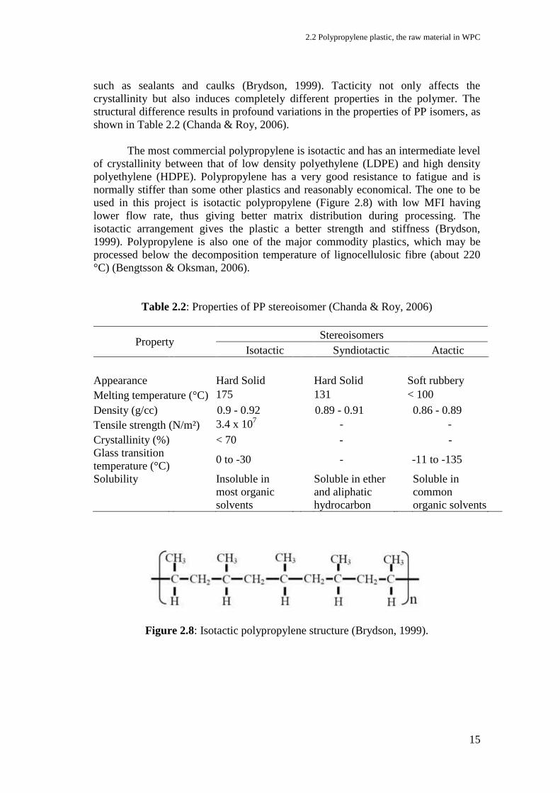
2.2 Polypropylene plastic, the raw material in WPC
15
such as sealants and caulks (Brydson, 1999). Tacticity not only affects the
crystallinity but also induces completely different properties in the polymer. The
structural difference results in profound variations in the properties of PP isomers, as
shown in Table 2.2 (Chanda & Roy, 2006).
The most commercial polypropylene is isotactic and has an intermediate level
of crystallinity between that of low density polyethylene (LDPE) and high density
polyethylene (HDPE). Polypropylene has a very good resistance to fatigue and is
normally stiffer than some other plastics and reasonably economical. The one to be
used in this project is isotactic polypropylene (Figure 2.8) with low MFI having
lower flow rate, thus giving better matrix distribution during processing. The
isotactic arrangement gives the plastic a better strength and stiffness (Brydson,
1999). Polypropylene is also one of the major commodity plastics, which may be
processed below the decomposition temperature of lignocellulosic fibre (about 220
°C) (Bengtsson & Oksman, 2006).
Table 2.2: Properties of PP stereoisomer (Chanda & Roy, 2006)
Property Stereoisomers
Isotactic Syndiotactic Atactic
Appearance Hard Solid Hard Solid Soft rubbery
Melting temperature (°C) 175 131 < 100
Density (g/cc) 0.9 - 0.92 0.89 - 0.91 0.86 - 0.89
Tensile strength (N/m²) 3.4 x 10⁷ - -
Crystallinity (%) < 70 - -
Glass transition
temperature (°C) 0 to -30 - -11 to -135
Solubility
Insoluble in
most organic
solvents
Soluble in ether
and aliphatic
hydrocarbon
Soluble in
common
organic solvents
Figure 2.8: Isotactic polypropylene structure (Brydson, 1999).
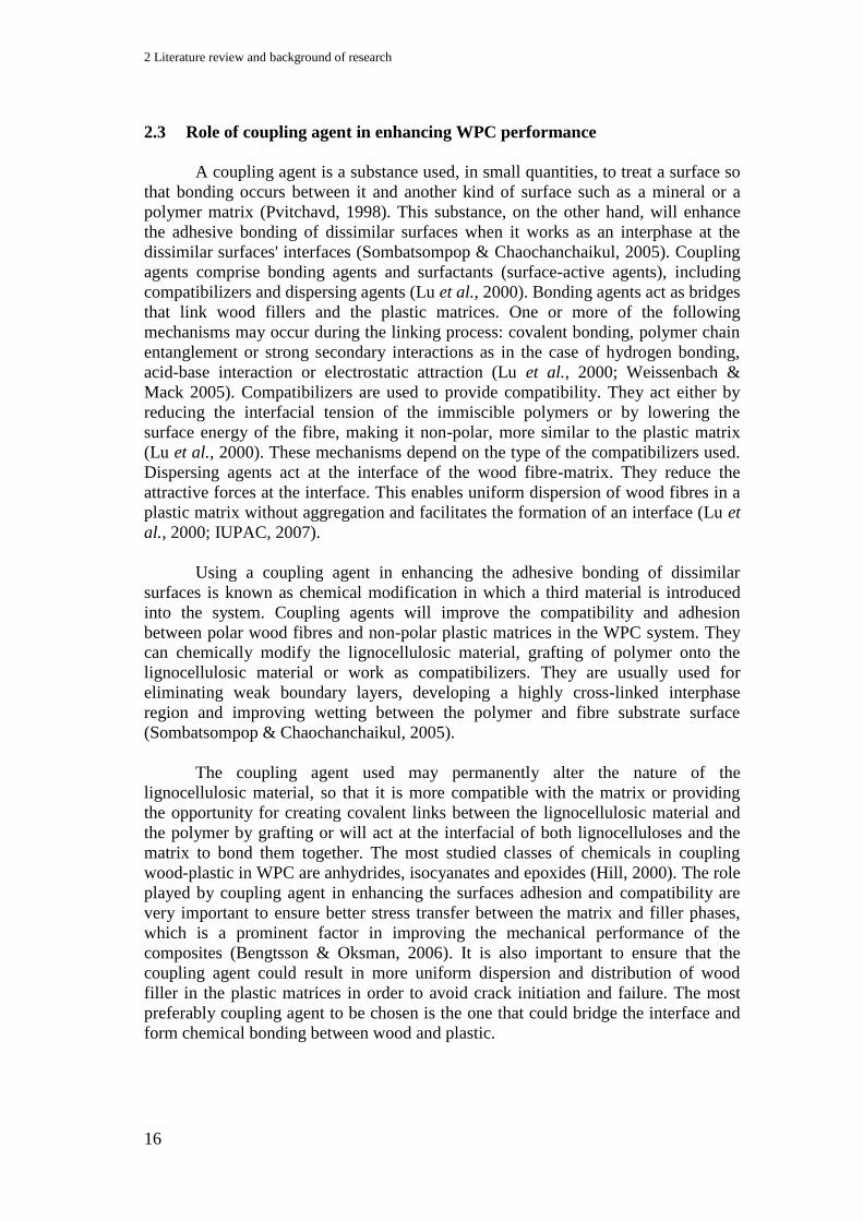
2 Literature review and background of research
16
2.3 Role of coupling agent in enhancing WPC performance
A coupling agent is a substance used, in small quantities, to treat a surface so
that bonding occurs between it and another kind of surface such as a mineral or a
polymer matrix (Pvitchavd, 1998). This substance, on the other hand, will enhance
the adhesive bonding of dissimilar surfaces when it works as an interphase at the
dissimilar surfaces' interfaces (Sombatsompop & Chaochanchaikul, 2005). Coupling
agents comprise bonding agents and surfactants (surface-active agents), including
compatibilizers and dispersing agents (Lu et al., 2000). Bonding agents act as bridges
that link wood fillers and the plastic matrices. One or more of the following
mechanisms may occur during the linking process: covalent bonding, polymer chain
entanglement or strong secondary interactions as in the case of hydrogen bonding,
acid-base interaction or electrostatic attraction (Lu et al., 2000; Weissenbach &
Mack 2005). Compatibilizers are used to provide compatibility. They act either by
reducing the interfacial tension of the immiscible polymers or by lowering the
surface energy of the fibre, making it non-polar, more similar to the plastic matrix
(Lu et al., 2000). These mechanisms depend on the type of the compatibilizers used.
Dispersing agents act at the interface of the wood fibre-matrix. They reduce the
attractive forces at the interface. This enables uniform dispersion of wood fibres in a
plastic matrix without aggregation and facilitates the formation of an interface (Lu et
al., 2000; IUPAC, 2007).
Using a coupling agent in enhancing the adhesive bonding of dissimilar
surfaces is known as chemical modification in which a third material is introduced
into the system. Coupling agents will improve the compatibility and adhesion
between polar wood fibres and non-polar plastic matrices in the WPC system. They
can chemically modify the lignocellulosic material, grafting of polymer onto the
lignocellulosic material or work as compatibilizers. They are usually used for
eliminating weak boundary layers, developing a highly cross-linked interphase
region and improving wetting between the polymer and fibre substrate surface
(Sombatsompop & Chaochanchaikul, 2005).
The coupling agent used may permanently alter the nature of the
lignocellulosic material, so that it is more compatible with the matrix or providing
the opportunity for creating covalent links between the lignocellulosic material and
the polymer by grafting or will act at the interfacial of both lignocelluloses and the
matrix to bond them together. The most studied classes of chemicals in coupling
wood-plastic in WPC are anhydrides, isocyanates and epoxides (Hill, 2000). The role
played by coupling agent in enhancing the surfaces adhesion and compatibility are
very important to ensure better stress transfer between the matrix and filler phases,
which is a prominent factor in improving the mechanical performance of the
composites (Bengtsson & Oksman, 2006). It is also important to ensure that the
coupling agent could result in more uniform dispersion and distribution of wood
filler in the plastic matrices in order to avoid crack initiation and failure. The most
preferably coupling agent to be chosen is the one that could bridge the interface and
form chemical bonding between wood and plastic.
2.3 Role of coupling agent in enhancing WPC performance
17
As a summary coupling agent reacts as follows:
Enhancing the adhesive bonding of dissimilar surfaces
Bridging the interphase
Covalent bonding
Polymer chain entanglement
Strong secondary interactions
Creating an interface bonding
Increase compatibility
Enable uniform dispersion of filler
Improve quality of filler/matrix interaction
Performing better mechanical properties
Figure 2.9: Coupling agent reaction (illustration from Specialchem4polymers)
Coupling agents are classified as organic, inorganic and organic-inorganic
compounds. Organic agents include isocyanates, anhydrides, amides, imides,
acrylates, chlorotriazines, epoxides, organic acids, monomers, polymers and
copolymers. For inorganic coupling agents, only silicates are used in WPC and
organic-inorganic agents include silanes and titanates (Lu et al., 2000). Organic
coupling agents usually have a bi- or multifunctional group that could interact with
the fibre to form covalent or hydrogen bonding or modify the polymer matrix by
graft biopolymerization or cross-linking at the interface depending on the functional
group types and the filler types. Inorganic coupling agents possibly act as dispersing
agents and counteract the polarity of wood surface to improve compatibility with the
matrix. The organic-inorganic agents are hybrid compounds in structure. They are
between organic and inorganic agents in function (Lu et al., 2000).
As for the WPC system, a lot of studies have been done using coupling agents
such as silanes, isocyanates, anhydrides or acrylates on the different wood fibre or
flour/plastic polymer systems (Raj et al., 1989; Bengtsson et al., 2006; Bengtsson et
al., 2005; Ichazo et al., 2006; Hu et al., 2006; Nachtigall et al., 1999). These
coupling agents chemically react with the wood surface at one end and on the other
2 Literature review and background of research
18
end interact with the matrix to improve stress transfer from the matrix to the wood.
Silane and isocyanates are reported to react with OH – groups on the wood surface to
form especially primary chemical bonds.
2.3.1 Organic peroxides
Organic peroxides commercially are used as oxidizing, epoxidizing, or
bleaching agents, as initiators for radical polymerization, and as curing agents (Reetz
et al., 2009). However over two decades ago researchers have reported that peroxides
can also work as a coupling agent in grafting the cellulose fibre directly to the
polyolefin polymer in a WPC system (Bataille et al., 1990; Sapieha et al.,1990).
Both benzoyl peroxide (BPO) and dicumyl peroxide (DCP) have been used as a pre-
treatment for wood fibres by Bataille et al. (1990) and to matrix by Sapieha et al.
(1990).
Peroxides will go through homolytic decomposition of the covalent bonds by
energy absorption to form free radicals. The energy includes almost any form,
including thermal, electromagnetic (ultraviolet and high-energy radiation),
particulate, electrical, sonic, and mechanical. Free radicals can undergo four general
types of reactions: (1) transfer or abstraction, (2) elimination, (3) addition, and (4)
combination or coupling. The free radicals react very rapidly thus the initiator must
be produced in the presence of the monomer that is to be polymerized (Reetz et al.,
2009). It is reported that peroxides had initiated free radicals and reacted between
cellulosic fibres and polyethylene matrix systems and grafted them together (Bataille
et al., 1990; Sapieha et al., 1990). Figure 2.10 shows the decomposition reactions of
some peroxide to initiate free radical (Bremner & Rudin, 1993).
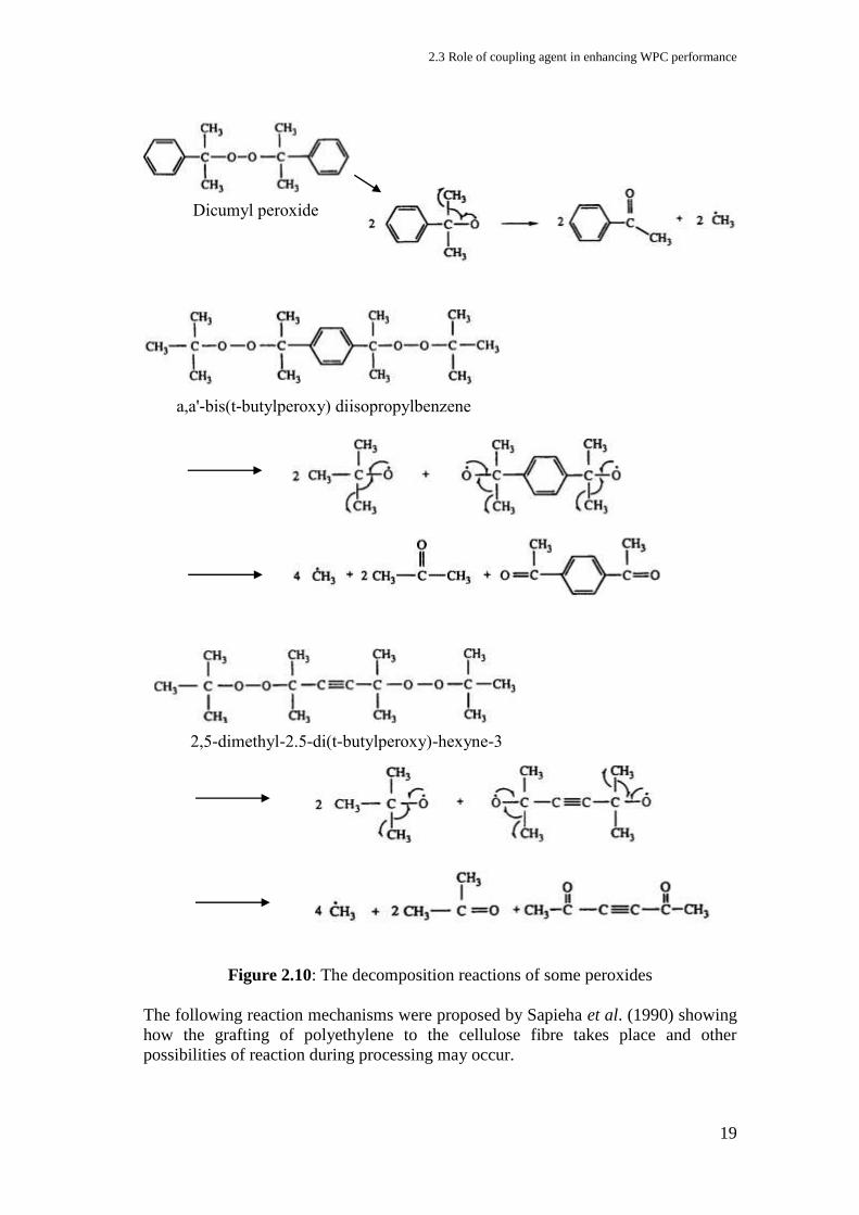
2.3 Role of coupling agent in enhancing WPC performance
19
Figure 2.10: The decomposition reactions of some peroxides
The following reaction mechanisms were proposed by Sapieha et al. (1990) showing
how the grafting of polyethylene to the cellulose fibre takes place and other
possibilities of reaction during processing may occur.
2,5-dimethyl-2.5-di(t-butylperoxy)-hexyne-3
a,a'-bis(t-butylperoxy) diisopropylbenzene
Dicumyl peroxide

2 Literature review and background of research
20
(1) Free radical reaction between PE and cellulose fibres
The hydrogen abstraction in cellulose may occur from OH – groups and C-H –
groups of the cellulose backbone as well as from methylol (-CH-OH) groups. On the
other hand, the hydrogen abstraction for PE may take place at tertiary carbons of the
alpha-olephin units because the LLDPE used was a copolymer of alphaolephins (i.e.,
butene, hexene, and octene) with ethylene.
(2) The following reactions may take place during the processing of composites:
(a) Increase of molecular weight and crosslinking of the polymer matrix by
combining macro-radicals of polyethylene
(b) Introduction of polar groups (such as acidic and ketonic) into the nonpolar
polyethylene chains by oxidative degradation
(c) Grafting of polyethylene onto cellulose fibres by combining cellulose and
polyethylene radicals

2.3 Role of coupling agent in enhancing WPC performance
21
Reactions (a) and (c) should lead to increase molecular weight and thus to higher
melt viscosities, while oxidative degradation (b) should lead to a decrease in
molecular weight. Peroxide concentration plays an important role in the efficiency of
these reactions while reaction (c) also depends on the available cellulose surface and,
therefore, on the concentration of cellulose fibres.
Even though the peroxides can be used alone as a coupling agent in a WPC
system, its application is wider and more reported as a radical initiator in grafting a
functional group from other coupling agents to bridge the interface in a WPC system.
Perhaps the better performance showed by the grafted coupling agent caused the
peroxides preferably to be used as a radical initiator in grafting, not as a coupling
agent itself. Examples are to graft anhydride group (Renner et al., 2010; Clemons,
2010; 2007; Ghaemy & Roohina, 2003) or a vinyl group (Bengtsson et al., 2005 &
2006) to a polyolefin. The following reaction (Figure 2.11) shows how DCP initiated
the grafting reaction of vinyl functional group from a silane coupling agent to a
polypropylene polymer backbone.
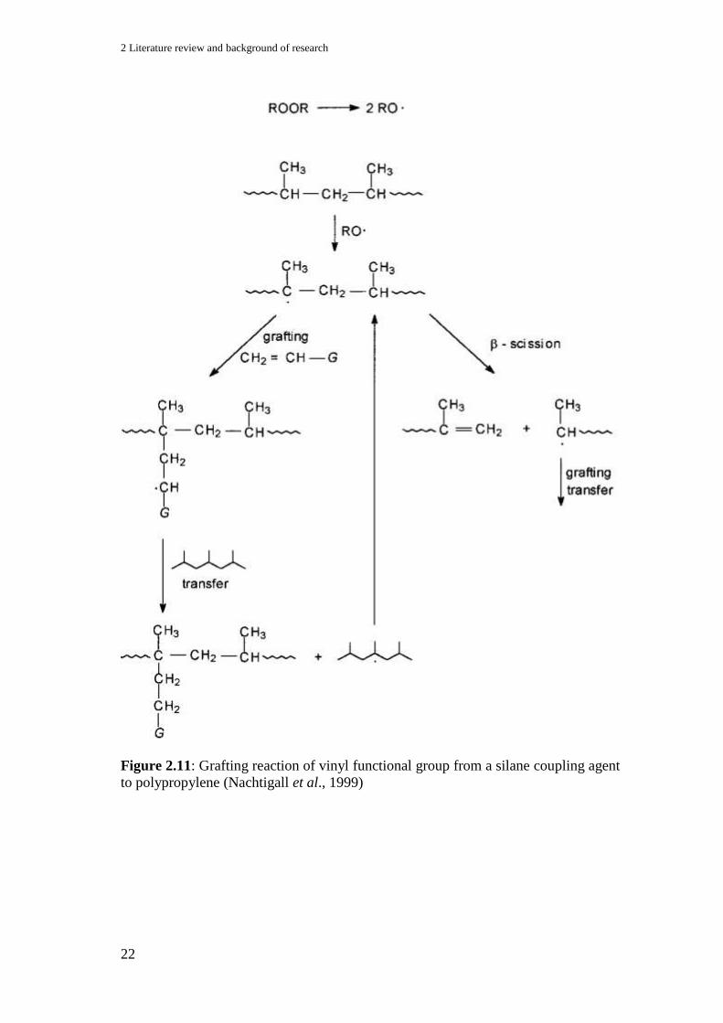
2 Literature review and background of research
22
Figure 2.11: Grafting reaction of vinyl functional group from a silane coupling agent
to polypropylene (Nachtigall et al., 1999)

2.3 Role of coupling agent in enhancing WPC performance
23
2.3.2 Silane coupling agents
Raj et al. (1989) used both isocyanates and silane coupling agents in cellulose
fibre/linear low-density polyethylene (LLDPE) composites by depositing these
molecules onto the fibres from a dilute solution. The fibres were dried before
compounding with the plastic in the extruder. They reported better properties with
the use of isocyanates as compared with silanes. Strength and ultimate failure strain
were improved using either of the coupling agents compared to the uncoupled
systems.
During processing, different adhesion mechanisms and interfacial interactions
may occur, and they may be in combination of several mechanisms depending on the
formulation or coupling agent used. It was proposed by Bengtsson et al. (2006) that
the following mechanisms (Figure 2.12) might have taken place in WPC when they
used vinyltrimethoxy silane as a coupling agent in a wood flour/polyethylene system
with DCP as the radical initiator. Acting as a radical initiator, DCP initiated free
radicals and performed covalent bondings between wood and PE. It was also
suggested earlier by Bengtsson et al. (2005) that a siloxane bridge is formed at the
wood surface, while the other end of the silane crosslinks with the HDPE.
Figure 2.12: Proposed bonding mechanisms in the silane cross-linked composites.
Covalent bonding between wood and PE through (1) condensation and (2) through
free radical reaction. Secondary interactions through (3) hydrogen bonding and (4)
van der Waals interaction Bengtsson et al. (2006).
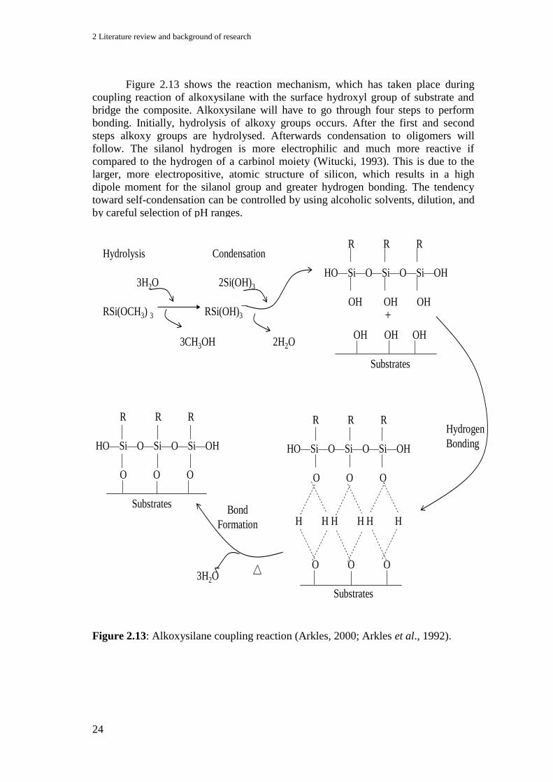
2 Literature review and background of research
24
Figure 2.13 shows the reaction mechanism, which has taken place during
coupling reaction of alkoxysilane with the surface hydroxyl group of substrate and
bridge the composite. Alkoxysilane will have to go through four steps to perform
bonding. Initially, hydrolysis of alkoxy groups occurs. After the first and second
steps alkoxy groups are hydrolysed. Afterwards condensation to oligomers will
follow. The silanol hydrogen is more electrophilic and much more reactive if
compared to the hydrogen of a carbinol moiety (Witucki, 1993). This is due to the
larger, more electropositive, atomic structure of silicon, which results in a high
dipole moment for the silanol group and greater hydrogen bonding. The tendency
toward self-condensation can be controlled by using alcoholic solvents, dilution, and
by careful selection of pH ranges.
Figure 2.13: Alkoxysilane coupling reaction (Arkles, 2000; Arkles et al., 1992).
Hydrogen
Bonding
+
OH OH OH
Substrates
R R R
HO—Si—O—Si—O—Si—OH
OH OH OH
Hydrolysis Condensation
3H2O 2Si(OH)3
RSi(OCH3) 3 RSi(OH)3
3CH3OH 2H2O
R R R
HO—Si—O—Si—O—Si—OH
O O O
H H H H H H
O O O
Substrates
3H2O
Bond
Formation
R R R
HO—Si—O—Si—O—Si—OH
O O O
Substrates

2.3 Role of coupling agent in enhancing WPC performance
25
As reported by Weissenbach and Mack (2005) and Xie et al. (2010), the rate
of this hydrolysis depends on the pH value of the hydrolysis medium as well as on
the type of organo- and silicon-functional groups. The alkoxy functional group on the
silicon compound has a significant influence on the hydrolysis rate. The order of
reactivity is as follows: propoxy << ethoxy < methoxy. Hydrolysis and condensation
rates of silane in different pH ranges can be expected as shows in the following
Figure 2.14.
Figure 2.14: Reactivity of silanes and silanols (Weissenbach & Mack, 2005)
According to Weissenbach & Mack (2005), silanols are most stable at around
pH 3, and their reactivity is higher at a pH lower than 1.5 or higher than 4.5. Silanols
condense to form oligomers and, ultimately, two- and three-dimensional networks.
Silanes, on the other hand, hydrolyse very quickly at very low pH. Relatively stable
silanols are formed and will form coordinated networks over time. Silanes are most
stable at neutral pH thus, hydrolyse very slowly to silanols, which are unstable and
condense. Both cases give a slow reaction in the transition from silanes to Si–O–Si
networks. At pH > 8, silanes become highly reactive once more and form silanols
very quickly. These silanols are very unstable and condense very quickly to give
uncoordinated Si–O–Si networks. The build-up of Si–O–Si networks cannot be
controlled and the uniform coating of the filler surface becomes more difficult
resulting in thicker, uncoordinated layers. These observations of the silanes
hydrolysis toward pH conditions are also reported by other researchers (Kang et al.,
1990; Wu et al., 2000; Miller & Berg, 2003; Xu et al., 2010)
Complete hydrolysis of functional trialkoxysilane takes place within a period
of few minutes to hours, depending on the nature of the functional group
(Weissenbach & Mack, 2005). The following substituents order also gives the
reactivity towards hydrolysis: alkyl < vinyl ≈ methacryloxy < mercapto < epoxy <
amino (Weissenbach & Mack, 2005). The following Table 2.3 shows the commercial
silane coupling agent available in industry.
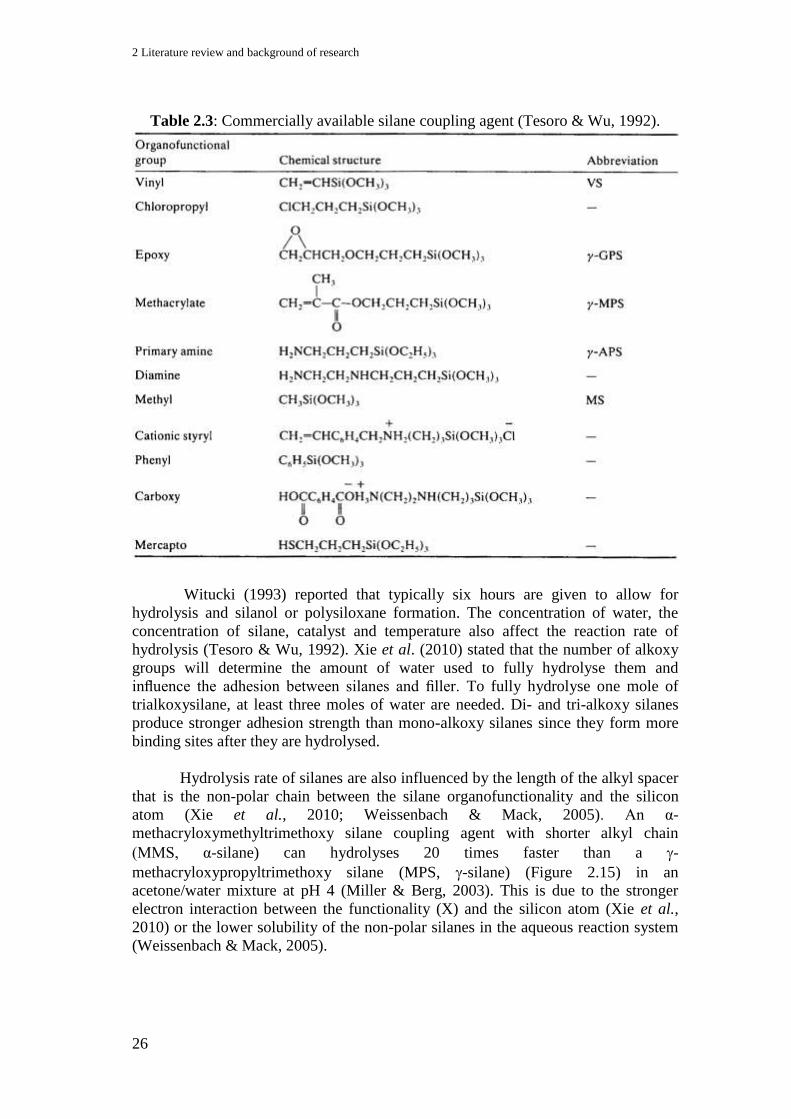
2 Literature review and background of research
26
Table 2.3: Commercially available silane coupling agent (Tesoro & Wu, 1992).
Witucki (1993) reported that typically six hours are given to allow for
hydrolysis and silanol or polysiloxane formation. The concentration of water, the
concentration of silane, catalyst and temperature also affect the reaction rate of
hydrolysis (Tesoro & Wu, 1992). Xie et al. (2010) stated that the number of alkoxy
groups will determine the amount of water used to fully hydrolyse them and
influence the adhesion between silanes and filler. To fully hydrolyse one mole of
trialkoxysilane, at least three moles of water are needed. Di- and tri-alkoxy silanes
produce stronger adhesion strength than mono-alkoxy silanes since they form more
binding sites after they are hydrolysed.
Hydrolysis rate of silanes are also influenced by the length of the alkyl spacer
that is the non-polar chain between the silane organofunctionality and the silicon
atom (Xie et al., 2010; Weissenbach & Mack, 2005). An α-
methacryloxymethyltrimethoxy silane coupling agent with shorter alkyl chain
(MMS, α-silane) can hydrolyses 20 times faster than a -
methacryloxypropyltrimethoxy silane (MPS, -silane) (Figure 2.15) in an
acetone/water mixture at pH 4 (Miller & Berg, 2003). This is due to the stronger
electron interaction between the functionality (X) and the silicon atom (Xie et al.,
2010) or the lower solubility of the non-polar silanes in the aqueous reaction system
(Weissenbach & Mack, 2005).

2.3 Role of coupling agent in enhancing WPC performance
27
a) b)
Figure 2.15: a) α-methacryloxymethyltrimethoxy silane and
b) -methacryloxypropyltrimethoxy silane (MPS, -silane)
2.3.3 Maleic anhydride coupling agents
Maleated polypropylene (MAPP) or maleated polyethylene (MAPE) has been
well established as compatibilizers for wood – PP or wood – PE composites (Renner
et al., 2010; Clemons, 2010; Chowdhury & Wolcott, 2007; Ghaemy & Roohina,
2003; Sanadi et al., 1994; Sapieha et al., 1990; Myers et al., 1991, Maldas & Kokta,
1991). The following Figure 2.16 shows the mechanism's steps involved in grafting
of maleic anhydride to the polyethylene to produce MA-g-PE. This process was done
in the presence of a peroxide radical initiator to promote reactions. This process is
normally used in WPC to help improving the parent polymers physicochemical
properties and to promote adhesion or crosslinking with the plastic matrix and
chemical covalent bonding and polar interaction with the wood materials.
Esterification will occur through the reaction of anhydride and the hydroxyl group of
the wood material. The reaction mechanism of the MAPP coupling agent in WPC is
as shown in Figure 2.17.
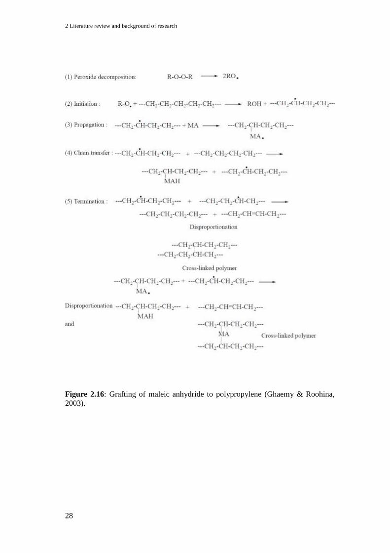
2 Literature review and background of research
28
Figure 2.16: Grafting of maleic anhydride to polypropylene (Ghaemy & Roohina,
2003).

2.3 Role of coupling agent in enhancing WPC performance
29
Figure 2.17: Esterification of cellulose by MAPP (Bledzki et al., 1996).
2.3.4 Isocyanates coupling agents
Isocyanates (–N=C=O) have been used as adhesive for wood based panels for
more than 25 years. Their main application is the production of exterior-grade
waterproof panels and also the production of panels from raw materials that are
difficult to glue like straw, bagasse, rice shells or sugar cane bagasse (Pizzi, 2005a).
The functional NCO – group is potentially reactive with the hydroxyl group from the
lignocellulose, making it suitable as a coupling agent in WPC system. The most
common polyisocyantes are based on aromatic isocyanates, toluene diisocyanates
(TDI) and methylene diphenyl diisocyantes (MDI). Aliphatic isocyanates include
those based on hexamethylene diisocyantes and isophorone diisocyanates.
Polyisocyanates that have been used in WPC are normally such as 4,4-
diphenylmethane diisocyanate (MDI), Toluene-2-4-diisocyanate (TDI) or 1,6-
diisocyanatohexane (DIC) 1-6 hexamethylene diisocyanate (HMDIC) and so on
(Gironès et al., 2007; Zhang et al., 2006; Qiu et al., 2005).
Normally the reaction of isocyanates group with hydroxyl group leads to the
formation of urethane bridges which will finally give to a hardened, crosslink
network:
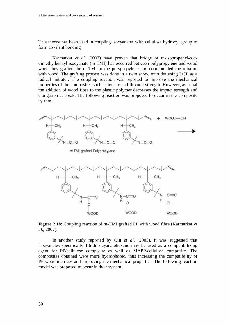
2 Literature review and background of research
30
This theory has been used in coupling isocyanates with cellulose hydroxyl group to
form covalent bonding.
Karmarkar et al. (2007) have proven that bridge of m-isopropenyl-α,α-
dimethylbenzyl-isocyanate (m-TMI) has occurred between polypropylene and wood
when they grafted the m-TMI to the polypropylene and compounded the mixture
with wood. The grafting process was done in a twin screw extruder using DCP as a
radical initiator. The coupling reaction was reported to improve the mechanical
properties of the composites such as tensile and flexural strength. However, as usual
the addition of wood fibre to the plastic polymer decreases the impact strength and
elongation at break. The following reaction was proposed to occur in the composite
system.
Figure 2.18: Coupling reaction of m-TMI grafted PP with wood fibre (Karmarkar et
al., 2007).
In another study reported by Qiu et al. (2005), it was suggested that
isocyanates specifically 1,6-diisocyanatohexane may be used as a compatibilizing
agent for PP/cellulose composite as well as MAPP/cellulose composite. The
composites obtained were more hydrophobic, thus increasing the compatibility of
PP-wood matrices and improving the mechanical properties. The following reaction
model was proposed to occur in their system.
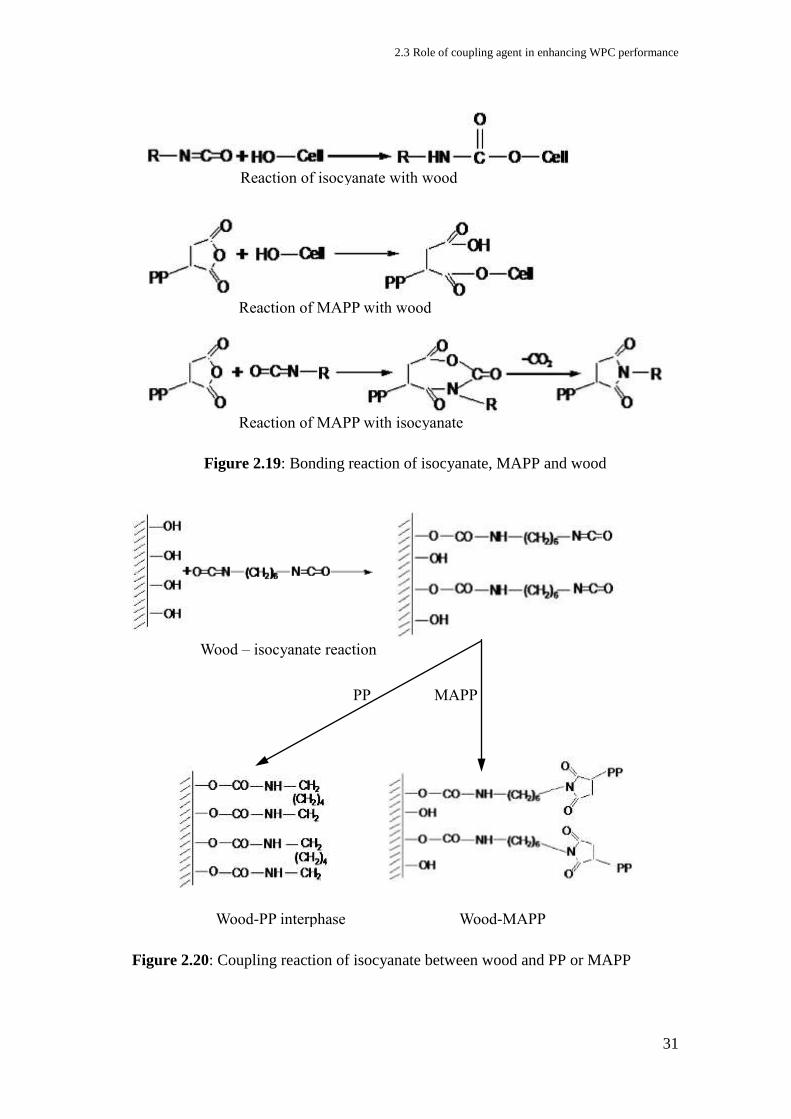
2.3 Role of coupling agent in enhancing WPC performance
31
Figure 2.19: Bonding reaction of isocyanate, MAPP and wood
Figure 2.20: Coupling reaction of isocyanate between wood and PP or MAPP
Reaction of isocyanate with wood
Reaction of MAPP with wood
Reaction of MAPP with isocyanate
PP MAPP
Wood-PP interphase Wood-MAPP
interphase
Wood – isocyanate reaction
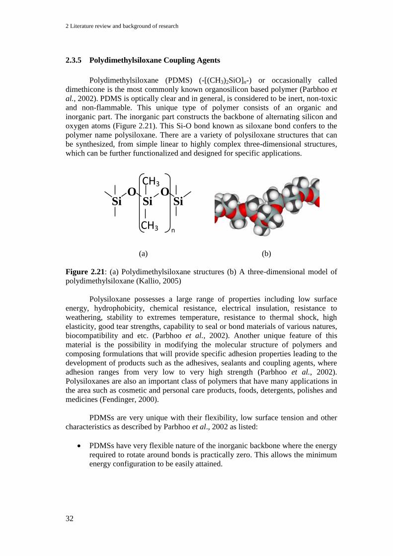
2 Literature review and background of research
32
2.3.5 Polydimethylsiloxane Coupling Agents
Polydimethylsiloxane (PDMS) (-[(CH3)2SiO]n-) or occasionally called
dimethicone is the most commonly known organosilicon based polymer (Parbhoo et
al., 2002). PDMS is optically clear and in general, is considered to be inert, non-toxic
and non-flammable. This unique type of polymer consists of an organic and
inorganic part. The inorganic part constructs the backbone of alternating silicon and
oxygen atoms (Figure 2.21). This Si-O bond known as siloxane bond confers to the
polymer name polysiloxane. There are a variety of polysiloxane structures that can
be synthesized, from simple linear to highly complex three-dimensional structures,
which can be further functionalized and designed for specific applications.
(a) (b)
Figure 2.21: (a) Polydimethylsiloxane structures (b) A three-dimensional model of
polydimethylsiloxane (Kallio, 2005)
Polysiloxane possesses a large range of properties including low surface
energy, hydrophobicity, chemical resistance, electrical insulation, resistance to
weathering, stability to extremes temperature, resistance to thermal shock, high
elasticity, good tear strengths, capability to seal or bond materials of various natures,
biocompatibility and etc. (Parbhoo et al., 2002). Another unique feature of this
material is the possibility in modifying the molecular structure of polymers and
composing formulations that will provide specific adhesion properties leading to the
development of products such as the adhesives, sealants and coupling agents, where
adhesion ranges from very low to very high strength (Parbhoo et al., 2002).
Polysiloxanes are also an important class of polymers that have many applications in
the area such as cosmetic and personal care products, foods, detergents, polishes and
medicines (Fendinger, 2000).
PDMSs are very unique with their flexibility, low surface tension and other
characteristics as described by Parbhoo et al., 2002 as listed:
PDMSs have very flexible nature of the inorganic backbone where the energy
required to rotate around bonds is practically zero. This allows the minimum
energy configuration to be easily attained.
Si Si Si O O
CH3
CH3 n
2.3 Role of coupling agent in enhancing WPC performance
33
They have a very low intermolecular force and large Si-O-Si bond angle
(149° at equilibrium) giving the ability to the methyl groups to closely pack
at the surface.
They have excellent low adhesion that is at the origin of release behaviour,
which prevents most materials from strongly adhering to them but
conversely, their low surface tension allows them to wet almost all surfaces.
They have low glass transition temperatures (Tg -125 °C) due to the flexibility
of the siloxane backbone and its large free volume and mobility.
The polymer also exhibits crystallization behaviour and displays a melting
transition temperature (T, -40 °C) that is dependent on the rate of cooling.
The large free volume and mobility of polysiloxanes give rise to a high
diffusion coefficient and high permeability of gases or vapours. Oxygen, for
example, diffuses through PDMS much more quickly than through other
polymers. Water vapour that has a low solubility value also passes through
PDMS very quickly due to its high diffusion coefficient.
The simplest forms of PDMS are straight chain polymers carrying no special
substituents and are generally sold according to viscosity or molecular weight (De
Poortere, 2005). Their chain length can vary to ten thousands giving a range of
viscosity from 0.65 to 2 500 000 centipoises. This allows the use of PDMS in the
form from water like fluid to flowable gum (Parbhoo et al., 2002). Specific
properties can be conferred on PDMS by substitution with functional groups. Groups
such as alkoxy, amino and mercapto will mainly interact with substrates by hydrogen
bonding. Others such as unsaturated or epoxy groups can cross-link by covalent bond
formation (De Poortere, 2005).
PDMSs have been widely used in other fields such as coating technology
(Esteves et al., 2010; Fang et al., 2010), membrane separation technology (Ulbricht,
2006; Li et al., 2010), nanocomposites (Chakrabarty, 2010; Ma et al., 2010) and in
rubber technology (Mani et al., 2010; Maxwell, 2009) and they work well to form
cross linking in the coating system and rubber technology and separate selectively in
membrane technology but to the best of our knowledge, the use of PDMS as a
coupling agent in the wood flour/PP system has not yet been reported.
Research on silicone materials as a coupling agent arose in the 1940s when
glass fibres were first used as reinforcement in unsaturated polyester (UP) resin.
However, it was silane and not polysiloxane appeared to be discovered earlier to
couple the composites’ component and enhanced the properties (Weissenbach &
Mack, 2005). Since then, a lot of researches and developments of silane as the
coupling agent has been made and reported in various composite systems (Bengtsson
& Oksman, 2006; Bengtsson et al., 2006; Ichazo et al., 2001; Pickering et al., 2003;
Hu et al., 2006). Chemical modification of fillers with silanes may generate the
following performance benefits as listed by Weissenbach and Mack (2005) and Edser
(2003):
Improved dimensional stability
Modified surface characteristics (water repellency or hydrophobicity)

2 Literature review and background of research
34
Improved wet-out between resin and filler
Decreased water-vapour transmission
Controlled rheological properties (higher loadings with no viscosity increase)
Improved filler dispersion (no filler agglomerates)
Improved mechanical properties and high retention under adverse conditions
Improved electrical properties
Silane coupling agents have been used in WPC for years and as been shown
previously in Table 2.3, there are various types of commercially available silane
coupling agent in the market. However, without having to go through the hydrolysis
and condensation steps which could be influenced by various factors and conditions
during a reaction, as explained in section 2.3.2, polysiloxane will offer a better
choice. More choices of functional groups could attach to them to give differences in
coupling reaction. Polysiloxane will also offer a more specific structure and
molecular weight information before coupling reaction takes place, which will help
in predicting or controlling the end product.
2.4 Theoretical Basis of Adhesion
In a composite system, bonding at an interface normally is due to adhesion
between filler and matrix. As has been explained in the previous literature review,
(the whole section 2.3) the adhesion between wood and plastic occurs at both wood
and plastic interfaces when a coupling agent is used. As shown in the reaction
mechanisms, the coupling agent normally will react with the free hydroxyl groups on
the wood surface at one end and the other end will bond with the plastic matrix. This
coupling reaction will bridge both wood and plastic surface together and is known as
an interphase in three-dimensional (Figure 2.22). It is the ability in sticking together
two surfaces so that stress can be transmitted between them. It can be quantified by
the amount of work which is required to pull two surfaces apart (Niska & Sanadi,
2008). The effect of the interphase on the properties of a composite material depends
on its amount and characteristics. It plays a very important role in determining
properties such as strength, toughness and long term properties such as creep and
moisture stability. Poor adhesion between filler and matrix in a composite system
decreases the adhesion between them. The following Figure 2.22 shows a schematic
of the adhesion mechanisms.
Figure 2.22: A schematic description of an interface and interphase in a cross-
section of WPC (Niska & Sanadi, 2008)
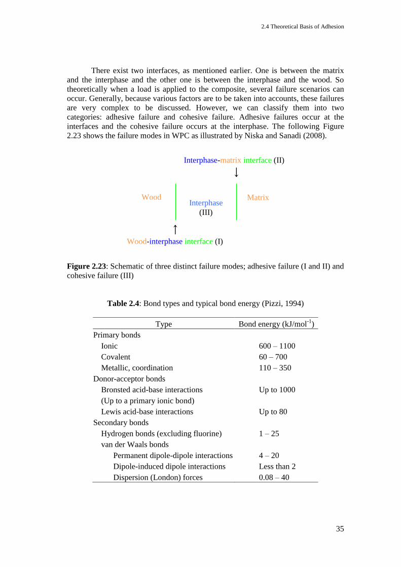
2.4 Theoretical Basis of Adhesion
35
There exist two interfaces, as mentioned earlier. One is between the matrix
and the interphase and the other one is between the interphase and the wood. So
theoretically when a load is applied to the composite, several failure scenarios can
occur. Generally, because various factors are to be taken into accounts, these failures
are very complex to be discussed. However, we can classify them into two
categories: adhesive failure and cohesive failure. Adhesive failures occur at the
interfaces and the cohesive failure occurs at the interphase. The following Figure
2.23 shows the failure modes in WPC as illustrated by Niska and Sanadi (2008).
Figure 2.23: Schematic of three distinct failure modes; adhesive failure (I and II) and
cohesive failure (III)
Table 2.4: Bond types and typical bond energy (Pizzi, 1994)
Type Bond energy (kJ/mol-1
)
Primary bonds
Ionic 600 – 1100
Covalent 60 – 700
Metallic, coordination 110 – 350
Donor-acceptor bonds
Bronsted acid-base interactions Up to 1000
(Up to a primary ionic bond)
Lewis acid-base interactions Up to 80
Secondary bonds
Hydrogen bonds (excluding fluorine) 1 – 25
van der Waals bonds
Permanent dipole-dipole interactions 4 – 20
Dipole-induced dipole interactions Less than 2
Dispersion (London) forces 0.08 – 40
Wood Interphase
(III)
Matrix
Wood-interphase interface (I)
Interphase-matrix interface (II)

2 Literature review and background of research
36
Theoretically there are five main mechanisms of adhesion that can occur at
the interface either in isolation or in combination to produce the bond. They are:
adsorption and wetting,
interdiffusion,
electrostatic attraction,
chemical bonding,
mechanical interlocking
(Hull, 1995).
Various types of bond can occur through these mechanisms, which can be grouped as
primary bond, donor-acceptor bond and secondary bond as listed in Table 2.4.
Figure 2.24: Bond formed by adsorption (illustration from SpecialChem)
(i) Adsorption and wetting mechanism occur when two electrically neutral
surfaces are brought sufficiently close together where a physical attraction takes
place (Hull, 1995). Normally interatomic and intermolecular forces between the
atoms and molecules of the two materials will take place (Parbhoo et al., 2002). In
the case of wood adhesion normally the secondary forces that are including the van
der Waals forces, hydrogen bonds and electrostatic interactions appeared to play the
dominand role (Pizzi, 1994). They are of great importance in achieving good
adhesive interactions between the two phases. If we take wood flour/PP surfaces as
an example, the adhesion is characterized by the degree of direct interfacial contact
between wood flour and PP polymer surfaces which is also called as wetting.
Wetting could be discussed further using contact angle and surface tension of
liquid drop on a solid surface theory (a short discussion is given in appendix 2,
appendixes section). Wetting can be improved by changing the surface energetics of
the system such as increasing the filler surface energy and/or lowering the polymer
surface energy. This can be achieved using suitable surface treatments or by addition
of interfacial active additives. PDMS based polysiloxane polymers appear to have a
very low liquid-vapour surface tension (LV) (~22 mN/m), which is lower than the
critical surface tension (C) of most substrates. Therefore, they could wet and spread
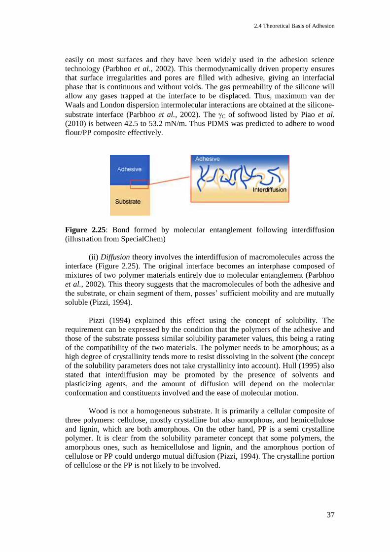
2.4 Theoretical Basis of Adhesion
37
easily on most surfaces and they have been widely used in the adhesion science
technology (Parbhoo et al., 2002). This thermodynamically driven property ensures
that surface irregularities and pores are filled with adhesive, giving an interfacial
phase that is continuous and without voids. The gas permeability of the silicone will
allow any gases trapped at the interface to be displaced. Thus, maximum van der
Waals and London dispersion intermolecular interactions are obtained at the silicone-
substrate interface (Parbhoo et al., 2002). The C of softwood listed by Piao et al.
(2010) is between 42.5 to 53.2 mN/m. Thus PDMS was predicted to adhere to wood
flour/PP composite effectively.
Figure 2.25: Bond formed by molecular entanglement following interdiffusion
(illustration from SpecialChem)
(ii) Diffusion theory involves the interdiffusion of macromolecules across the
interface (Figure 2.25). The original interface becomes an interphase composed of
mixtures of two polymer materials entirely due to molecular entanglement (Parbhoo
et al., 2002). This theory suggests that the macromolecules of both the adhesive and
the substrate, or chain segment of them, posses’ sufficient mobility and are mutually
soluble (Pizzi, 1994).
Pizzi (1994) explained this effect using the concept of solubility. The
requirement can be expressed by the condition that the polymers of the adhesive and
those of the substrate possess similar solubility parameter values, this being a rating
of the compatibility of the two materials. The polymer needs to be amorphous; as a
high degree of crystallinity tends more to resist dissolving in the solvent (the concept
of the solubility parameters does not take crystallinity into account). Hull (1995) also
stated that interdiffusion may be promoted by the presence of solvents and
plasticizing agents, and the amount of diffusion will depend on the molecular
conformation and constituents involved and the ease of molecular motion.
Wood is not a homogeneous substrate. It is primarily a cellular composite of
three polymers: cellulose, mostly crystalline but also amorphous, and hemicellulose
and lignin, which are both amorphous. On the other hand, PP is a semi crystalline
polymer. It is clear from the solubility parameter concept that some polymers, the
amorphous ones, such as hemicellulose and lignin, and the amorphous portion of
cellulose or PP could undergo mutual diffusion (Pizzi, 1994). The crystalline portion
of cellulose or the PP is not likely to be involved.
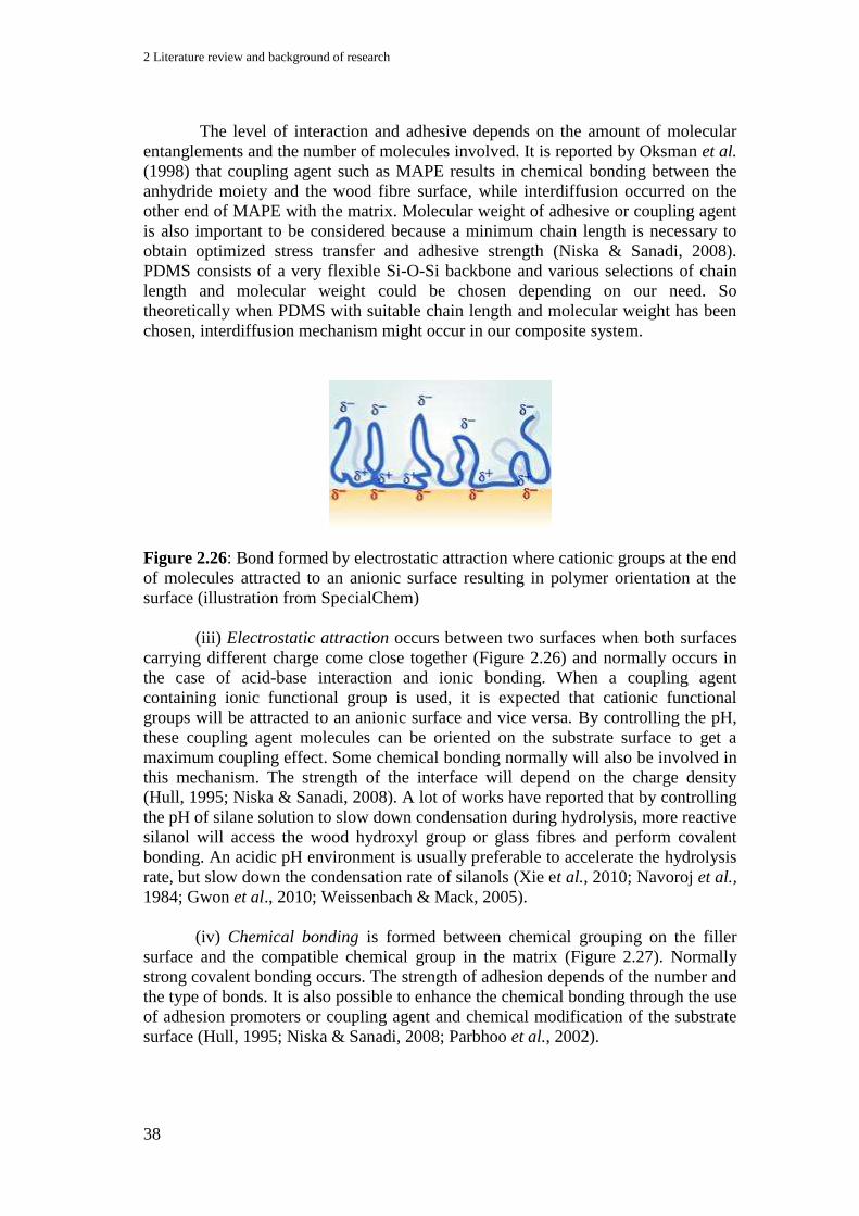
2 Literature review and background of research
38
The level of interaction and adhesive depends on the amount of molecular
entanglements and the number of molecules involved. It is reported by Oksman et al.
(1998) that coupling agent such as MAPE results in chemical bonding between the
anhydride moiety and the wood fibre surface, while interdiffusion occurred on the
other end of MAPE with the matrix. Molecular weight of adhesive or coupling agent
is also important to be considered because a minimum chain length is necessary to
obtain optimized stress transfer and adhesive strength (Niska & Sanadi, 2008).
PDMS consists of a very flexible Si-O-Si backbone and various selections of chain
length and molecular weight could be chosen depending on our need. So
theoretically when PDMS with suitable chain length and molecular weight has been
chosen, interdiffusion mechanism might occur in our composite system.
Figure 2.26: Bond formed by electrostatic attraction where cationic groups at the end
of molecules attracted to an anionic surface resulting in polymer orientation at the
surface (illustration from SpecialChem)
(iii) Electrostatic attraction occurs between two surfaces when both surfaces
carrying different charge come close together (Figure 2.26) and normally occurs in
the case of acid-base interaction and ionic bonding. When a coupling agent
containing ionic functional group is used, it is expected that cationic functional
groups will be attracted to an anionic surface and vice versa. By controlling the pH,
these coupling agent molecules can be oriented on the substrate surface to get a
maximum coupling effect. Some chemical bonding normally will also be involved in
this mechanism. The strength of the interface will depend on the charge density
(Hull, 1995; Niska & Sanadi, 2008). A lot of works have reported that by controlling
the pH of silane solution to slow down condensation during hydrolysis, more reactive
silanol will access the wood hydroxyl group or glass fibres and perform covalent
bonding. An acidic pH environment is usually preferable to accelerate the hydrolysis
rate, but slow down the condensation rate of silanols (Xie et al., 2010; Navoroj et al.,
1984; Gwon et al., 2010; Weissenbach & Mack, 2005).
(iv) Chemical bonding is formed between chemical grouping on the filler
surface and the compatible chemical group in the matrix (Figure 2.27). Normally
strong covalent bonding occurs. The strength of adhesion depends of the number and
the type of bonds. It is also possible to enhance the chemical bonding through the use
of adhesion promoters or coupling agent and chemical modification of the substrate
surface (Hull, 1995; Niska & Sanadi, 2008; Parbhoo et al., 2002).
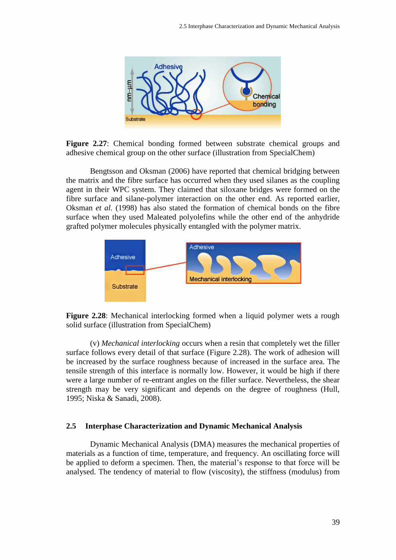
2.5 Interphase Characterization and Dynamic Mechanical Analysis
39
Figure 2.27: Chemical bonding formed between substrate chemical groups and
adhesive chemical group on the other surface (illustration from SpecialChem)
Bengtsson and Oksman (2006) have reported that chemical bridging between
the matrix and the fibre surface has occurred when they used silanes as the coupling
agent in their WPC system. They claimed that siloxane bridges were formed on the
fibre surface and silane-polymer interaction on the other end. As reported earlier,
Oksman et al. (1998) has also stated the formation of chemical bonds on the fibre
surface when they used Maleated polyolefins while the other end of the anhydride
grafted polymer molecules physically entangled with the polymer matrix.
Figure 2.28: Mechanical interlocking formed when a liquid polymer wets a rough
solid surface (illustration from SpecialChem)
(v) Mechanical interlocking occurs when a resin that completely wet the filler
surface follows every detail of that surface (Figure 2.28). The work of adhesion will
be increased by the surface roughness because of increased in the surface area. The
tensile strength of this interface is normally low. However, it would be high if there
were a large number of re-entrant angles on the filler surface. Nevertheless, the shear
strength may be very significant and depends on the degree of roughness (Hull,
1995; Niska & Sanadi, 2008).
2.5 Interphase Characterization and Dynamic Mechanical Analysis
Dynamic Mechanical Analysis (DMA) measures the mechanical properties of
materials as a function of time, temperature, and frequency. An oscillating force will
be applied to deform a specimen. Then, the material’s response to that force will be
analysed. The tendency of material to flow (viscosity), the stiffness (modulus) from
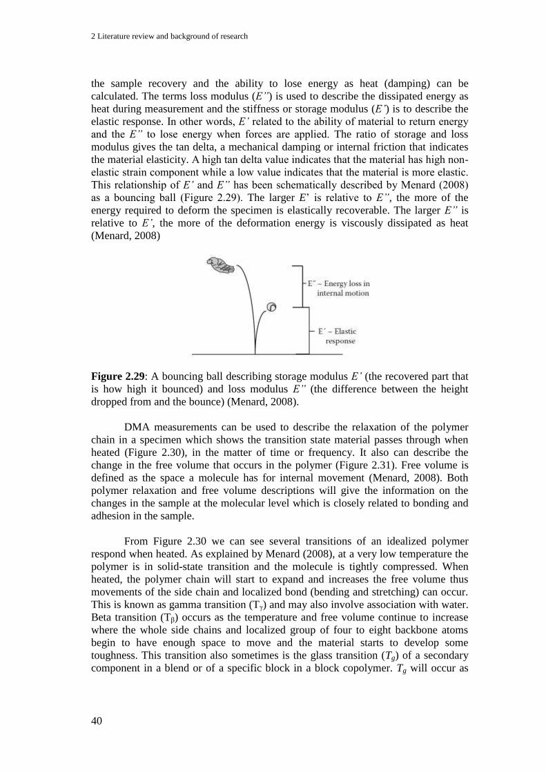
2 Literature review and background of research
40
the sample recovery and the ability to lose energy as heat (damping) can be
calculated. The terms loss modulus (E”) is used to describe the dissipated energy as
heat during measurement and the stiffness or storage modulus (E’) is to describe the
elastic response. In other words, E’ related to the ability of material to return energy
and the E” to lose energy when forces are applied. The ratio of storage and loss
modulus gives the tan delta, a mechanical damping or internal friction that indicates
the material elasticity. A high tan delta value indicates that the material has high non-
elastic strain component while a low value indicates that the material is more elastic.
This relationship of E’ and E” has been schematically described by Menard (2008)
as a bouncing ball (Figure 2.29). The larger E’ is relative to E”, the more of the
energy required to deform the specimen is elastically recoverable. The larger E” is
relative to E’, the more of the deformation energy is viscously dissipated as heat
(Menard, 2008)
Figure 2.29: A bouncing ball describing storage modulus E’ (the recovered part that
is how high it bounced) and loss modulus E” (the difference between the height
dropped from and the bounce) (Menard, 2008).
DMA measurements can be used to describe the relaxation of the polymer
chain in a specimen which shows the transition state material passes through when
heated (Figure 2.30), in the matter of time or frequency. It also can describe the
change in the free volume that occurs in the polymer (Figure 2.31). Free volume is
defined as the space a molecule has for internal movement (Menard, 2008). Both
polymer relaxation and free volume descriptions will give the information on the
changes in the sample at the molecular level which is closely related to bonding and
adhesion in the sample.
From Figure 2.30 we can see several transitions of an idealized polymer
respond when heated. As explained by Menard (2008), at a very low temperature the
polymer is in solid-state transition and the molecule is tightly compressed. When
heated, the polymer chain will start to expand and increases the free volume thus
movements of the side chain and localized bond (bending and stretching) can occur.
This is known as gamma transition (Tγ) and may also involve association with water.
Beta transition (Tβ) occurs as the temperature and free volume continue to increase
where the whole side chains and localized group of four to eight backbone atoms
begin to have enough space to move and the material starts to develop some
toughness. This transition also sometimes is the glass transition (Tg) of a secondary
component in a blend or of a specific block in a block copolymer. Tg will occur as
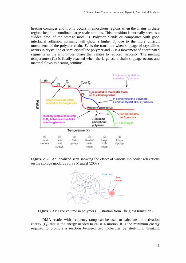
2.5 Interphase Characterization and Dynamic Mechanical Analysis
41
heating continues and it only occurs in amorphous regions when the chains in these
regions begin to coordinate large-scale motions. This transition is normally seen as a
sudden drop of the storage modulus. Polymer blends or composites with good
interfacial adhesion normally will show a higher Tg due to the more difficult
movements of the polymer chain. Tα* is the transition when slippage of crystallites
occurs in crystalline or semi crystalline polymer and Tll is a movement of coordinated
segments in the amorphous phase that relates to reduced viscosity. The melting
temperature (Tm) is finally reached when the large-scale chain slippage occurs and
material flows as heating continue.
Figure 2.30: An idealized scan showing the effect of various molecular relaxations
on the storage modulus curve Menard (2008)
Figure 2.31: Free volume in polymer (illustration from The glass transition)
DMA results with frequency ramp can be used to calculate the activation
energy (Ea) that is the energy needed to cause a motion. It is the minimum energy
required to promote a reaction between two molecules by stretching, breaking
Free
volume
Chain end
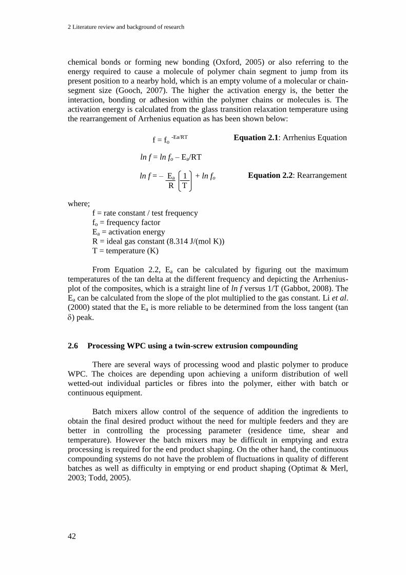
2 Literature review and background of research
42
chemical bonds or forming new bonding (Oxford, 2005) or also referring to the
energy required to cause a molecule of polymer chain segment to jump from its
present position to a nearby hold, which is an empty volume of a molecular or chain-
segment size (Gooch, 2007). The higher the activation energy is, the better the
interaction, bonding or adhesion within the polymer chains or molecules is. The
activation energy is calculated from the glass transition relaxation temperature using
the rearrangement of Arrhenius equation as has been shown below:
Equation 2.1: Arrhenius Equation
Equation 2.2: Rearrangement
where;
f = rate constant / test frequency
fo = frequency factor
Ea = activation energy
R = ideal gas constant (8.314 J/(mol K))
T = temperature (K)
From Equation 2.2, Ea can be calculated by figuring out the maximum
temperatures of the tan delta at the different frequency and depicting the Arrhenius-
plot of the composites, which is a straight line of ln f versus 1/T (Gabbot, 2008). The
Ea can be calculated from the slope of the plot multiplied to the gas constant. Li et al.
(2000) stated that the Ea is more reliable to be determined from the loss tangent (tan
) peak.
2.6 Processing WPC using a twin-screw extrusion compounding
There are several ways of processing wood and plastic polymer to produce
WPC. The choices are depending upon achieving a uniform distribution of well
wetted-out individual particles or fibres into the polymer, either with batch or
continuous equipment.
Batch mixers allow control of the sequence of addition the ingredients to
obtain the final desired product without the need for multiple feeders and they are
better in controlling the processing parameter (residence time, shear and
temperature). However the batch mixers may be difficult in emptying and extra
processing is required for the end product shaping. On the other hand, the continuous
compounding systems do not have the problem of fluctuations in quality of different
batches as well as difficulty in emptying or end product shaping (Optimat & Merl,
2003; Todd, 2005).
f = fo -Ea/RT
ln f = ln fo – Ea/RT
ln f = – Ea 1 + ln fo
R T

2.6 Processing WPC using a twin-screw extrusion compounding
43
For most applications in processing composites, extruders, either single-
screw or twin-screw, normally become the first choice to achieve the desired
compounds. This is because of the various tasks being able to be accomplished in
extrusion compounding as listed by Todd (2005):
Metering and feeding of the ingredients
Melting of solid-fed polymers
Break-up of agglomerates
Providing uniform distribution of the filler
Venting
Developing pressure for discharge.
Avoiding excessive screw and barrel wear
Minimizing energy consumption.
There may be significant differences between single- and twin-screw
extruders in how they achieve the above functions. However a single screw extruder
normally has more disadvantages compared to a twin screw extruder such as poor
mixing characteristics, lower output rate, greater risk of burning and so on (Optimat
& Merl, 2003).
Twin-screw extruders (Figure 2.32) are classified as intermeshing or non-
intermeshing, and co-rotating or counter-rotating with parallel or conical screw.
Figure 2.33 shows the different between the conical and parallel screw.
Figure 2.32: Co-rotating intermeshing twin-screw extruder (Todd, 2005).
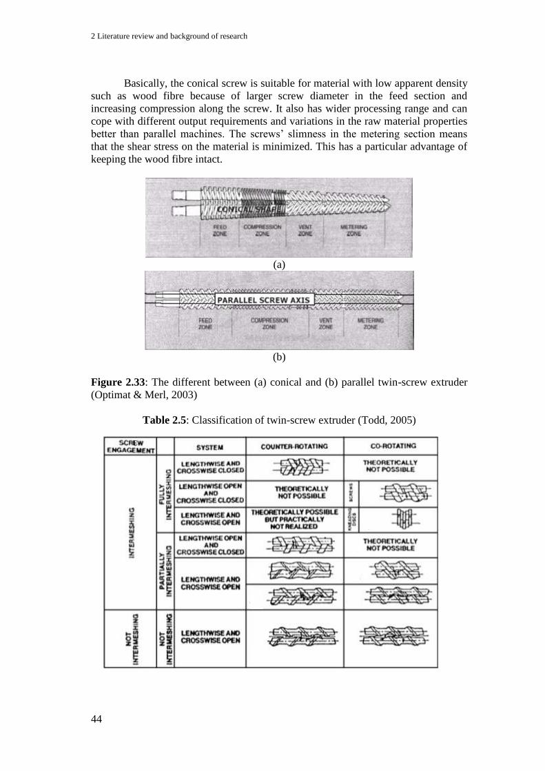
2 Literature review and background of research
44
Basically, the conical screw is suitable for material with low apparent density
such as wood fibre because of larger screw diameter in the feed section and
increasing compression along the screw. It also has wider processing range and can
cope with different output requirements and variations in the raw material properties
better than parallel machines. The screws’ slimness in the metering section means
that the shear stress on the material is minimized. This has a particular advantage of
keeping the wood fibre intact.
(a)
(b)
Figure 2.33: The different between (a) conical and (b) parallel twin-screw extruder
(Optimat & Merl, 2003)
Table 2.5: Classification of twin-screw extruder (Todd, 2005)
E
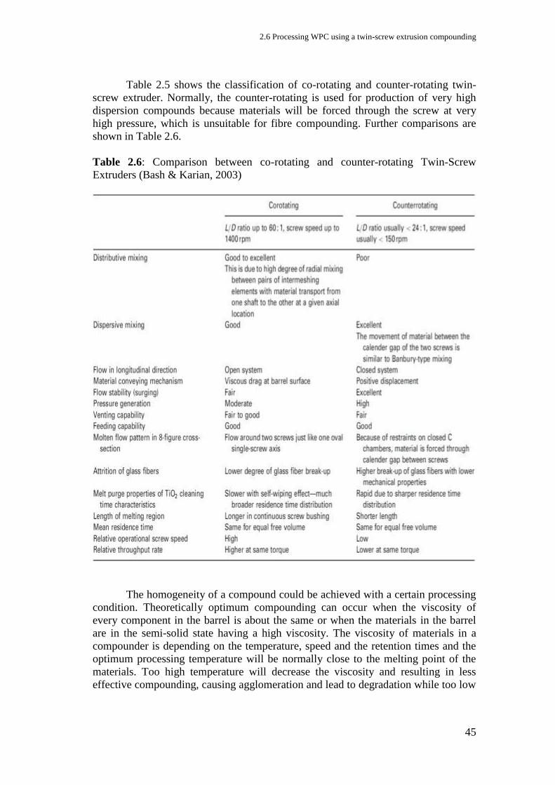
2.6 Processing WPC using a twin-screw extrusion compounding
45
Table 2.5 shows the classification of co-rotating and counter-rotating twin-
screw extruder. Normally, the counter-rotating is used for production of very high
dispersion compounds because materials will be forced through the screw at very
high pressure, which is unsuitable for fibre compounding. Further comparisons are
shown in Table 2.6.
Table 2.6: Comparison between co-rotating and counter-rotating Twin-Screw
Extruders (Bash & Karian, 2003)
The homogeneity of a compound could be achieved with a certain processing
condition. Theoretically optimum compounding can occur when the viscosity of
every component in the barrel is about the same or when the materials in the barrel
are in the semi-solid state having a high viscosity. The viscosity of materials in a
compounder is depending on the temperature, speed and the retention times and the
optimum processing temperature will be normally close to the melting point of the
materials. Too high temperature will decrease the viscosity and resulting in less
effective compounding, causing agglomeration and lead to degradation while too low
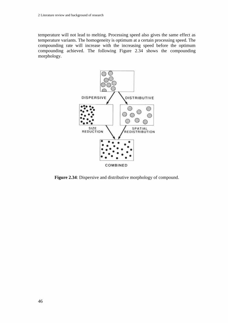
2 Literature review and background of research
46
temperature will not lead to melting. Processing speed also gives the same effect as
temperature variants. The homogeneity is optimum at a certain processing speed. The
compounding rate will increase with the increasing speed before the optimum
compounding achieved. The following Figure 2.34 shows the compounding
morphology.
Figure 2.34: Dispersive and distributive morphology of compound.
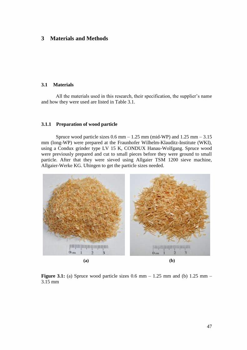
47
3 Materials and Methods
3.1 Materials
All the materials used in this research, their specification, the supplier’s name
and how they were used are listed in Table 3.1.
3.1.1 Preparation of wood particle
Spruce wood particle sizes 0.6 mm – 1.25 mm (mid-WP) and 1.25 mm – 3.15
mm (long-WP) were prepared at the Fraunhofer Wilhelm-Klauditz-Institute (WKI),
using a Condux grinder type LV 15 K, CONDUX Hanau-Wolfgang. Spruce wood
were previously prepared and cut to small pieces before they were ground to small
particle. After that they were sieved using Allgaier TSM 1200 sieve machine,
Allgaier-Werke KG. Uhingen to get the particle sizes needed.
Figure 3.1: (a) Spruce wood particle sizes 0.6 mm – 1.25 mm and (b) 1.25 mm –
3.15 mm
(b) (a)

3 Materials and Methods
48
Table 3.1: Materials and supplier
Material Specification
Supplier
Application
Lignocel BK 40/90 wood
flour (WF).
Cubic structure sizes 300 µm – 500 µm from
selected conifers.
J. Rettenmaier and
Söhne GmbH + Co.
KG, Rosenberg,
Germany
Used as received
Spruce wood particle
Sizes 0.6 mm – 1.25 mm (mid-WP) and 1.25 mm
– 3.15 mm (long-WP)
WKI, Fraunhofer
Institute for Wood
Research,
Braunschweigh,
Germany
Sieved using Allgaier
TSM 1200 sieve
machine, Allgaier-
werke KG. Uhingen.
Polypropylene (PP)
Medium isotactic homopolymers
MFR of 10.5 g/10min and density of 905 kg/m3
Sabic Deutschland
GmbH and Co.
Gelsenkirchen,
Germany.
Ground to grain size
using Condux grinder
type LV 15K,
CONDUX Hanau-
Wolfgang.
Coupling agents with 100%
purity:
i) TEGOMER V-Si 4042
(Vinyl PDMS)
Insoluble in water with density of 0.971 g/cm³
1 functionality ~10 000 g/mol
n to m ratio ± 1 to 133
Evonik Goldschmidt
GmbH, Essen,
Germany.
Used as received in
isopropanol solution

3.1 Materials
49
Table 3.1: Materials and supplier (continued)
ii) TEGOMER VB 2706
(Triethoxy PDMS)
Insoluble in water with density of 0.999 g/cm³
1 C(OEt)3 ~ 5 000 g/mol
l to m ratio ± 1 to 64

3 Materials and Methods
50
Table 3.1: Materials and supplier (continued)
iii) Bifunctional Triethoxy-
vinyl PDMS
- TEGOMER V-Si 4042
batch VB 3242
- TEGOMER V-Si 4042
batch VB 3247
- TEGOMER V-Si 4042
batch VB 3248
Low molecular weight
2 500 g/mol with <100 Si units per backbone
High molecular weight
12 000 g/mol with ± 250 Si units per backbone
Very high molecular weight
30 000 g/mol with >>250 Si units per backbone
These are specially
synthesized materials.
Most of the
information was kept
confidential.
Combining the little
information provided,
the possible structure
predicted is shown
with unknown ratio
of l, m and n.
iv) Coupling agent with
50% very high
molecular weight
bifunctional triethoxy-
vinyl PDMS:
Containing the same structure as iii) with the
very high molecular weight properties.
Evonik Goldschmidt
GmbH, Essen,
Germany
Used as received
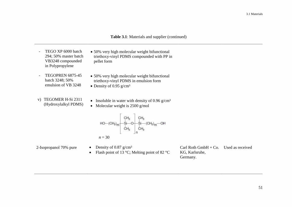
3.1 Materials
51
Table 3.1: Materials and supplier (continued)
- TEGO XP 6000 batch
294; 50% master batch
VB3248 compounded
in Polypropylene
- TEGOPREN 6875-45
batch 3248; 50%
emulsion of VB 3248
v) TEGOMER H-Si 2311
(Hydroxylalkyl PDMS)
2-Isopropanol 70% pure
50% very high molecular weight bifunctional
triethoxy-vinyl PDMS compounded with PP in
pellet form
50% very high molecular weight bifunctional
triethoxy-vinyl PDMS in emulsion form
Density of 0.95 g/cm³
Insoluble in water with density of 0.96 g/cm³
Molecular weight is 2500 g/mol
n = 30
Density of 0.87 g/cm³
Flash point of 13 °C; Melting point of 82 °C
Carl Roth GmbH + Co.
KG, Karlsruhe,
Germany.
Used as received

3 Materials and Methods
52
Table 3.1: Materials and supplier (continued)
PEROXAN DC Dicumyl
peroxide (DCP) 99%
Crystal pellet with melting point of 35 – 45 °C
Decomposition temperature: + 80 °C
Half life time: 10 hours at 112 °C, 1 hour at 132
°C and 1 min at 172 °C
PERGAN GmbH,
Bocholt, Germany
Used as received
Licocene PP MA 6252 Fine
Grain TP (MAPP)
A low molecular, maleic anhydride-modified PP
Graft content of 7% maleic anhydride
Melting point of approximately 140 °C
Clariant GmbH,
Gersthofen, Germany
Used as received
Acetone with 99.5% purity
Density of 0.79 g/cm³
Flash point of < -18 °C; Boiling range of 55.8
56.6 °C
Carl Roth GmbH + Co.
KG, Karlsruhe,
Germany
Used as received
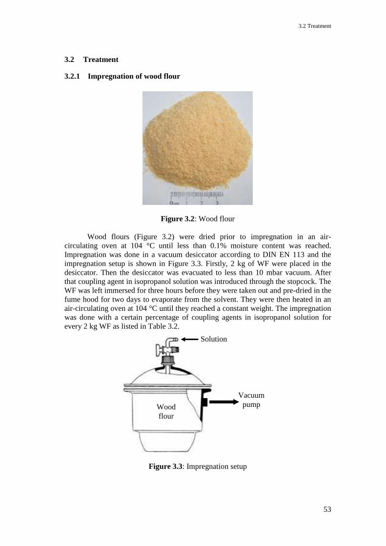
3.2 Treatment
53
3.2 Treatment
3.2.1 Impregnation of wood flour
Figure 3.2: Wood flour
Wood flours (Figure 3.2) were dried prior to impregnation in an air-
circulating oven at 104 °C until less than 0.1% moisture content was reached.
Impregnation was done in a vacuum desiccator according to DIN EN 113 and the
impregnation setup is shown in Figure 3.3. Firstly, 2 kg of WF were placed in the
desiccator. Then the desiccator was evacuated to less than 10 mbar vacuum. After
that coupling agent in isopropanol solution was introduced through the stopcock. The
WF was left immersed for three hours before they were taken out and pre-dried in the
fume hood for two days to evaporate from the solvent. They were then heated in an
air-circulating oven at 104 °C until they reached a constant weight. The impregnation
was done with a certain percentage of coupling agents in isopropanol solution for
every 2 kg WF as listed in Table 3.2.
Figure 3.3: Impregnation setup
Vacuum
pump
Solution
Wood
flour
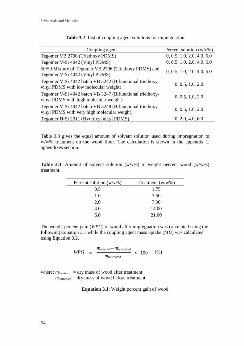
3 Materials and Methods
54
Table 3.2: List of coupling agent solutions for impregnation
Coupling agent Percent solution (w/v%)
Tegomer VB 2706 (Triethoxy PDMS) 0, 0.5, 1.0, 2.0, 4.0, 6.0
Tegomer V-Si 4042 (Vinyl PDMS) 0, 0.5, 1.0, 2.0, 4.0, 6.0
50/50 Mixture of Tegomer VB 2706 (Triethoxy PDMS) and
Tegomer V-Si 4042 (Vinyl PDMS) 0, 0.5, 1.0, 2.0, 4.0, 6.0
Tegomer V-Si 4042 batch VB 3242 (Bifunctional triethoxy-
vinyl PDMS with low molecular weight) 0, 0.5, 1.0, 2.0
Tegomer V-Si 4042 batch VB 3247 (Bifunctional triethoxy-
vinyl PDMS with high molecular weight) 0, 0.5, 1.0, 2.0
Tegomer V-Si 4042 batch VB 3248 (Bifunctional triethoxy-
vinyl PDMS with very high molecular weight) 0, 0.5, 1.0, 2.0
Tegomer H-Si 2311 (Hydroxyl alkyl PDMS) 0, 2.0, 4.0, 6.0
Table 3.3 gives the equal amount of solvent solution used during impregnation to
w/w% treatment on the wood flour. The calculation is shown in the appendix 1,
appendixes section.
Table 3.3: Amount of solvent solution (w/v%) to weight percent wood (w/w%)
treatment.
Percent solution (w/v%) Treatment (w/w%)
0.5 1.75
1.0 3.50
2.0 7.00
4.0 14.00
6.0 21.00
The weight percent gain (WPG) of wood after impregnation was calculated using the
following Equation 3.1 while the coupling agent mass uptake (MU) was calculated
using Equation 3.2.
where: mtreated = dry mass of wood after treatment
muntreated = dry mass of wood before treatment
Equation 3.1: Weight percent gain of wood
muntreated =
mtreated – muntreated WPG x 100 (%)
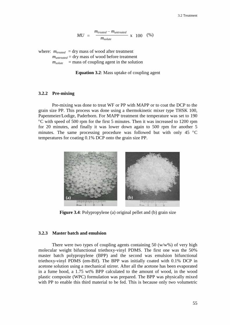
3.2 Treatment
55
where: mtreated = dry mass of wood after treatment
muntreated = dry mass of wood before treatment
msolute = mass of coupling agent in the solution
Equation 3.2: Mass uptake of coupling agent
3.2.2 Pre-mixing
Pre-mixing was done to treat WF or PP with MAPP or to coat the DCP to the
grain size PP. This process was done using a thermokinetic mixer type THSK 100,
Papenmeier/Lodige, Paderborn. For MAPP treatment the temperature was set to 190
C with speed of 500 rpm for the first 5 minutes. Then it was increased to 1200 rpm
for 20 minutes, and finally it was lower down again to 500 rpm for another 5
minutes. The same processing procedure was followed but with only 45 C
temperatures for coating 0.1% DCP onto the grain size PP.
Figure 3.4: Polypropylene (a) original pellet and (b) grain size
3.2.3 Master batch and emulsion
There were two types of coupling agents containing 50 (w/w%) of very high
molecular weight bifunctional triethoxy-vinyl PDMS. The first one was the 50%
master batch polypropylene (BPP) and the second was emulsion bifunctional
triethoxy-vinyl PDMS (em-Bif). The BPP was initially coated with 0.1% DCP in
acetone solution using a mechanical stirrer. After all the acetone has been evaporated
in a fume hood, a 1.75 wt% BPP calculated to the amount of wood, in the wood
plastic composite (WPC) formulation was prepared. The BPP was physically mixed
with PP to enable this third material to be fed. This is because only two volumetric
= mtreated – muntreated
msolute
MU x 100 (%)
(a) (a) (b)
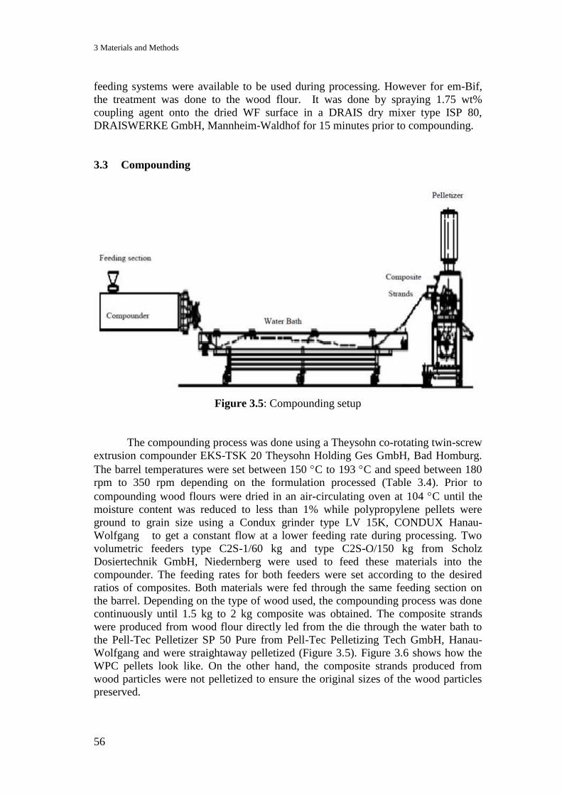
3 Materials and Methods
56
feeding systems were available to be used during processing. However for em-Bif,
the treatment was done to the wood flour. It was done by spraying 1.75 wt%
coupling agent onto the dried WF surface in a DRAIS dry mixer type ISP 80,
DRAISWERKE GmbH, Mannheim-Waldhof for 15 minutes prior to compounding.
3.3 Compounding
Figure 3.5: Compounding setup
The compounding process was done using a Theysohn co-rotating twin-screw
extrusion compounder EKS-TSK 20 Theysohn Holding Ges GmbH, Bad Homburg.
The barrel temperatures were set between 150 C to 193 C and speed between 180
rpm to 350 rpm depending on the formulation processed (Table 3.4). Prior to
compounding wood flours were dried in an air-circulating oven at 104 C until the
moisture content was reduced to less than 1% while polypropylene pellets were
ground to grain size using a Condux grinder type LV 15K, CONDUX Hanau-
Wolfgang to get a constant flow at a lower feeding rate during processing. Two
volumetric feeders type C2S-1/60 kg and type C2S-O/150 kg from Scholz
Dosiertechnik GmbH, Niedernberg were used to feed these materials into the
compounder. The feeding rates for both feeders were set according to the desired
ratios of composites. Both materials were fed through the same feeding section on
the barrel. Depending on the type of wood used, the compounding process was done
continuously until 1.5 kg to 2 kg composite was obtained. The composite strands
were produced from wood flour directly led from the die through the water bath to
the Pell-Tec Pelletizer SP 50 Pure from Pell-Tec Pelletizing Tech GmbH, Hanau-
Wolfgang and were straightaway pelletized (Figure 3.5). Figure 3.6 shows how the
WPC pellets look like. On the other hand, the composite strands produced from
wood particles were not pelletized to ensure the original sizes of the wood particles
preserved.
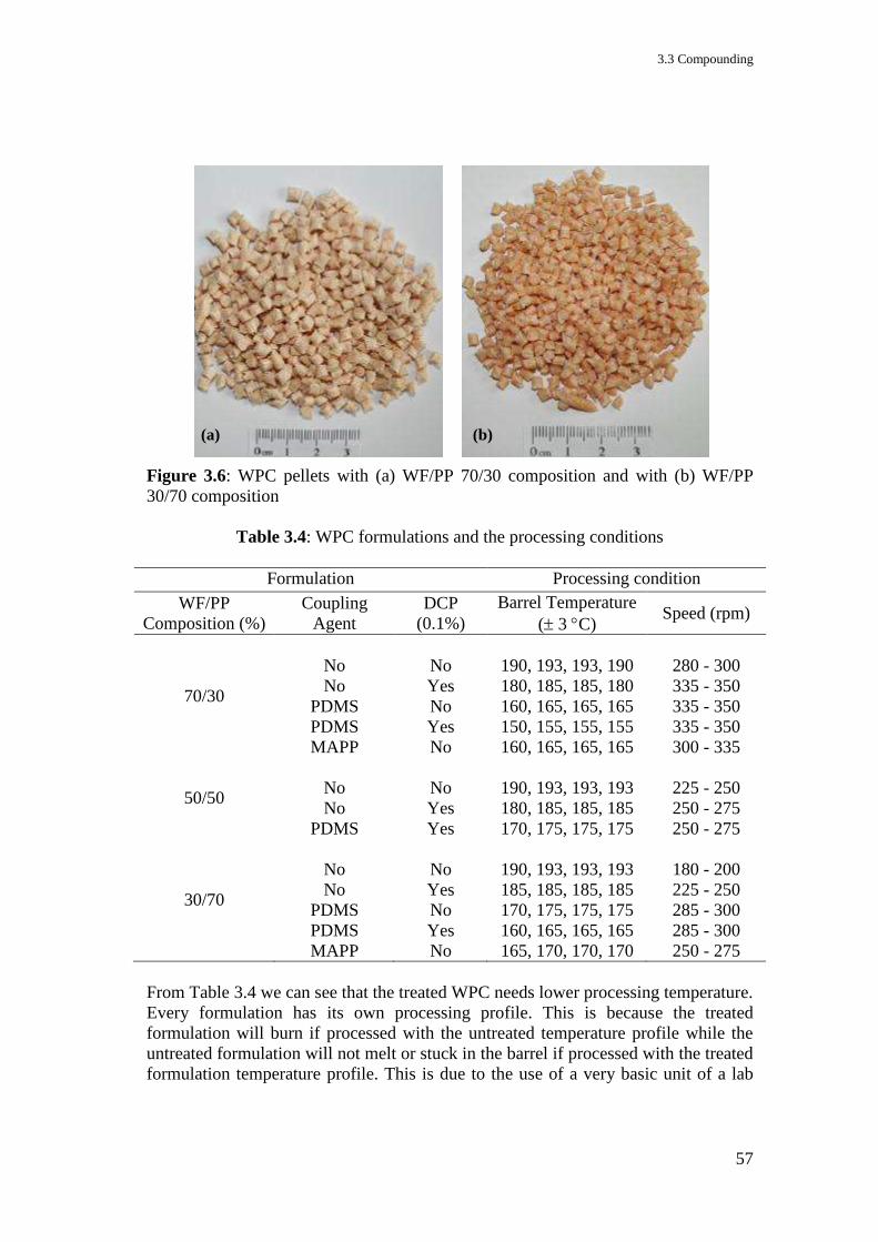
3.3 Compounding
57
Figure 3.6: WPC pellets with (a) WF/PP 70/30 composition and with (b) WF/PP
30/70 composition
Table 3.4: WPC formulations and the processing conditions
Formulation Processing condition
WF/PP
Composition (%)
Coupling
Agent
DCP
(0.1%)
Barrel Temperature
( 3 C) Speed (rpm)
70/30
No
No
PDMS
PDMS
MAPP
No
Yes
No
Yes
No
190, 193, 193, 190
180, 185, 185, 180
160, 165, 165, 165
150, 155, 155, 155
160, 165, 165, 165
280 - 300
335 - 350
335 - 350
335 - 350
300 - 335
50/50
No
No
PDMS
No
Yes
Yes
190, 193, 193, 193
180, 185, 185, 185
170, 175, 175, 175
225 - 250
250 - 275
250 - 275
30/70
No
No
PDMS
PDMS
MAPP
No
Yes
No
Yes
No
190, 193, 193, 193
185, 185, 185, 185
170, 175, 175, 175
160, 165, 165, 165
165, 170, 170, 170
180 - 200
225 - 250
285 - 300
285 - 300
250 - 275
From Table 3.4 we can see that the treated WPC needs lower processing temperature.
Every formulation has its own processing profile. This is because the treated
formulation will burn if processed with the untreated temperature profile while the
untreated formulation will not melt or stuck in the barrel if processed with the treated
formulation temperature profile. This is due to the use of a very basic unit of a lab
(a) (b)
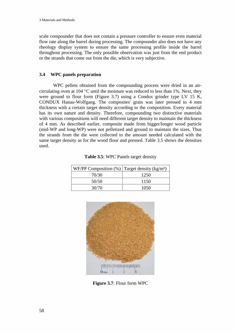
3 Materials and Methods
58
scale compounder that does not contain a pressure controller to ensure even material
flow rate along the barrel during processing. The compounder also does not have any
rheology display system to ensure the same processing profile inside the barrel
throughout processing. The only possible observation was just from the end product
or the strands that come out from the die, which is very subjective.
3.4 WPC panels preparation
WPC pellets obtained from the compounding process were dried in an air-
circulating oven at 104 C until the moisture was reduced to less than 1%. Next, they
were ground to flour form (Figure 3.7) using a Condux grinder type LV 15 K,
CONDUX Hanau-Wolfgang. The composites' grain was later pressed to 4 mm
thickness with a certain target density according to the composition. Every material
has its own nature and density. Therefore, compounding two distinctive materials
with various compositions will need different target density to maintain the thickness
of 4 mm. As described earlier, composite made from bigger/longer wood particle
(mid-WP and long-WP) were not pelletized and ground to maintain the sizes. Thus
the strands from the die were collected to the amount needed calculated with the
same target density as for the wood flour and pressed. Table 3.5 shows the densities
used.
Table 3.5: WPC Panels target density
WF/PP Composition (%) Target density (kg/m³)
70/30 1250
50/50 1150
30/70 1050
Figure 3.7: Flour form WPC
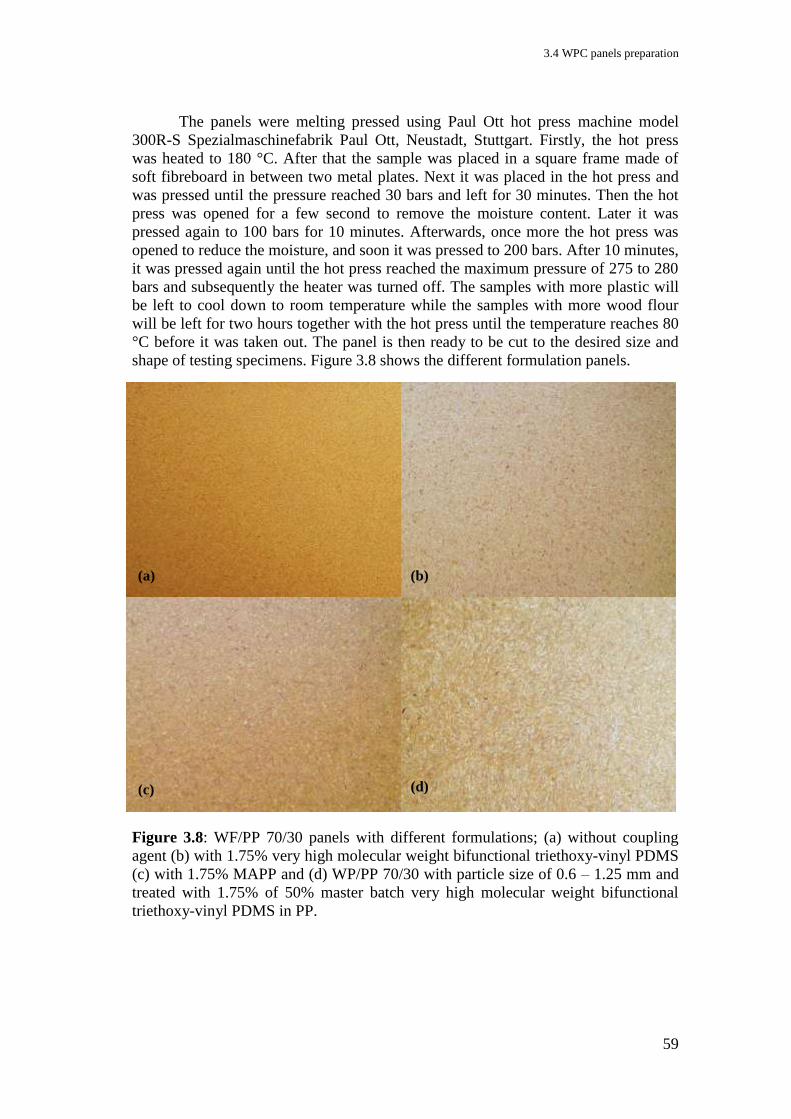
3.4 WPC panels preparation
59
The panels were melting pressed using Paul Ott hot press machine model
300R-S Spezialmaschinefabrik Paul Ott, Neustadt, Stuttgart. Firstly, the hot press
was heated to 180 °C. After that the sample was placed in a square frame made of
soft fibreboard in between two metal plates. Next it was placed in the hot press and
was pressed until the pressure reached 30 bars and left for 30 minutes. Then the hot
press was opened for a few second to remove the moisture content. Later it was
pressed again to 100 bars for 10 minutes. Afterwards, once more the hot press was
opened to reduce the moisture, and soon it was pressed to 200 bars. After 10 minutes,
it was pressed again until the hot press reached the maximum pressure of 275 to 280
bars and subsequently the heater was turned off. The samples with more plastic will
be left to cool down to room temperature while the samples with more wood flour
will be left for two hours together with the hot press until the temperature reaches 80
°C before it was taken out. The panel is then ready to be cut to the desired size and
shape of testing specimens. Figure 3.8 shows the different formulation panels.
Figure 3.8: WF/PP 70/30 panels with different formulations; (a) without coupling
agent (b) with 1.75% very high molecular weight bifunctional triethoxy-vinyl PDMS
(c) with 1.75% MAPP and (d) WP/PP 70/30 with particle size of 0.6 – 1.25 mm and
treated with 1.75% of 50% master batch very high molecular weight bifunctional
triethoxy-vinyl PDMS in PP.
(a) (b)
(c) (d)

3 Materials and Methods
60
3.5 Testing and analysing
3.5.1 Mechanical properties
Mechanical properties of WPC were determined through the flexural test,
tensile test and impact test. The flexural test was done according to the DIN EN ISO
178 standard. The specimens were cut to a dimension of 80 mm x 10 mm x 4 mm
and were tested at 2 mm/min of test speed using a three-point bending test until the
specimen fractures or until the deformation reaches some predetermined value. The
tensile test was done according to the DIN EN ISO 527-1 with the test speed of also
2 mm/min. The specimens were prepared according to DIN EN ISO 527-2 type 1B,
which is a dumb-bell-shaped with overall length of 150 mm, measurement width of
10 mm and thickness of 4 mm as shown in Figure 2.8. In this test, the specimen was
extended along its longitudinal axis with the gauge length of 50 0.5 mm until the
specimen fractures. Both tests were done using Zwick 1474 universal testing
machine. However, due to the technical problem during the tensile mode machine,
not all the tensile test results could be taken into account.
The impact test was done according to DIN EN ISO 179-1, which is referred
to a flatwise impacted unnotched specimen with the dimensions of 80 mm x 10 mm x
4 mm using Zwick D 7900 impact testing machine with 1 J - pendulum. All
mechanical testing results were taken from an average reading of at least eight
specimens for every formulation. All specimens were placed in the conditioning
room at relative air humidity of 65% and temperature of 20 C prior to testing until
they gained less than 1% of weight after 24 hours. The specimens were then weighed
to the nearest 0.001 g. Figure 3.9 shows how the specimens were cut out of the
panels for testing.
Figure 3.9: Specimens cutting arrangement
3.5 Testing and analysing
61
3.5.2 Water absorption test
Water absorption was conducted according to DIN EN 317 standard method
to determine the swelling in thickness and the dimensional changes of panels.
Specimens were measured prior and after a total immersion into water during 28
days. Reading was taken after 24 hours and on the 7th
, 14th
, 21st and 28
th day, from
the average measurement of eight specimens’ size 50 mm x 50 mm x 4 mm as shown
in Figure 3.9.
Water uptake (w) of specimens was determined using the following equation:
where: wwet = weight after immersion
woriginal = initial weight after equilibration at 20 C and 65% relative humidity.
Equation 3.3: Water uptake calculation
A dimensional change (d) of specimens is referring to the changes in volume
and was determined using the following equation:
where: dwet = dimension after immersion
doriginal = initial dimension after equilibration at 20 C and 65% relative
humidity.
Equation 3.4: Dimensional change calculation
3.5.3 Moisture absorption test
Moisture absorption test was done using treated and untreated wood flour at
ambient temperature and humidity in the storeroom. 5 g of every sample were
weighed and were oven dried at 104 °C for 24 hours. Every formulation was done
using three specimens for accuracy. After that, the specimens were analysed for
moisture content, and then were left open in the store for 25 days. The moisture
content was analysed using Ultra-X moisture analyser model UX 2081. The reading
was taken after one hour, five hours, 24 hours, five days and every five days until
day 25th
.
= wwet – woriginal
woriginal w x 100 (%)
= dwet – doriginal
doriginal d x 100 (%)
3 Materials and Methods
62
3.5.4 Thermal analysis
Thermal analysis was performed using a dynamic mechanical analyser
(DMA); Tritec 2000, Triton Technology Ltd, Keyworth, United Kingdom in a dual
cantilever mode. The specimens were cut to the size of 35 mm x 6 mm x 2 mm and
scanned with the dynamic temperature from -40 C to 120 C. Sequential frequencies
of 0.1 Hz, 1 Hz and 10 Hz were used during measurement with amplitude of 50 m.
Liquid nitrogen was used to cool down the specimen to below -40 C prior to
measurement and the constant heating rate of 2 C/min was used to collect the data.
Four specimens were tested for every formulation.
3.5.5 ATR-FTIR analysis
Attenuated total reflection - fourier transform infrared analysis (ATR-FTIR)
was done using a Thermo-Nicolet IMPACT 410 spectrometer, Thermo Fisher
Scientific Inc., Germany with OMNIC 2.1 analysis software. Every analysis was run
with 32 scans with three specimens of every sample. For treated wood in WPC, the
specimens were analysed after soxhlet extraction of the wood flour for 24 hours in
xylene solution. The extraction was done to see the existence of covalent bonding
between the coupling agent and the wood flour.
3.5.6 SEM/SEM-EDX
Scanning electron microscopy (SEM) and energy dispersive X-ray
spectroscopy (EDX) were performed using SEM Leo 1530 with primary electron
energy, Eo of 1.5 kV and Oxford EDX system with Ge detector. All specimens were
sputtered coated with iron prior to analyses for better imaging and two specimens
were done for every formulation.
3.5.7 Microscopic image analysis
Microscopic analysis was carried out using Carl Zeiss Axioplan 1, light
microscope from Switzerland. WPC panels with 4 mm thickness were cut out to the
size of about 10 mm x 15 mm and were put it the hot wax for 15 minutes. After they
have cooled, thin slices of 20 μm were microtomed from the waxed specimens.
Waxing was done to give better dimensional stability during slicing. The sliced
specimens were then submerged in isopropanol for half an hour to dissolve the wax
and finally stained with an aqueous solution of 0.5% toluidine blue. Toluidine blue
was used to stain the wood with blue colour so that it could be differentiated from the
plastic matrices. Next, the specimens were rinsed with water, mounted onto glass
slides and covered by cover glass. Three specimens were analysed for every
formulation.

3.5 Testing and analysing
63
3.5.8 Free sugar analysis
Free sugar analysis was done on the 70/30 WF/PP composites with and
without 1.75% very high molecular weight bifunctional triethoxy-vinyl PDMS
coupling agent. First the composites were ground to a fine powder that could be
passed through 0.5 mm sieve using the Condux grinder type V3, CONDUX Hanau-
Wolfgang. Then 5 g of the fine powders were extracted in 50 ml distilled water and
heat up in an autoclave (CERTO clar Hochdrucksterilisator Traun, Austria) at 120
°C, 1.5 bar for 45 minutes. The solutions were then cooled down to room
temperature before they were centrifuged using Eppendorf centrifuge 5412,
Hamburg with 11 000 xg speed for 15 minutes. After that the solutions were filtered
using Amicon Ultra centrifugal filter Millipore, Ireland with 3 MWCO membranes.
The sugar analysis was done using Dionex high performance anion exchange system
ICS 3000 chromatograph, USA with pulsed amperometric detection. NaOH was used
in the mobile phase column and anion capture CarboPac PA20 in the solid phase
column. Every formulation was analyzed using two solvent specimens. The
specimens were injected for analysis using an auto-sampling system and were run for
65 minutes with four standard solution calibrations. The following method was used
during the analysis.
Eluent: 1: Water
2: 20 mmol/1 NaOH
3: 500 mmol/1 NaOH
Flow: 0.4 ml/min
System pressure: 30 MPa
Detector: IPAD
Temperature: 30 °C
Injection volume: 10 µl

3 Materials and Methods
64
3.5.9 Overall processing procedure
The following figure shows the schematic of overall processing procedure in
producing the composites as has been done in this doctorate thesis
Figure 3.10: Overall processing procedure
Samples
cutting
Hot
Press
FTIR, Moisture
analyses
WPC Flour
PP
Treated/
untreated
Wood
Wood
Impregnation
/Treatment
Samples
Compounder Pelletizer
Hot
Pres
s
Grinder
WPC Pellet
WPC Panels Testing/
analyzing
Testing machines
65
4 Influence of the coupling agent amount on the performance of
WF/PP composites
One of the factors influencing the performance of WPC is the amount of
treatments used in the formulation. The structure and properties of the interphase
change with the amount of coupling agents used (Ishida & Miller, 1984). Too much
or as well too little coupling agent will not have a positive effect on the performance.
Thus optimization is necessary in order to achieve maximum efficiency. Throughout
this research, a trend on the optimum range of the treatment amount has been found,
which improves the performance of the WPC.
First, the composites were produced using wood flour treated with single
functionality PDMS coupling agents. Here vinyl PDMS (TEGOMER V-Si 4042) and
triethoxy PDMS (TEGOMER VB 2706) and 50/50 percentage mixture of both vinyl
PDMS and triethoxy PDMS coupling agents were used. Then, bifunctional coupling
agents with different molecular weight were used to treat the wood flour, here the
bifunctional triethoxy-vinyl PDMS with low molecular weight, high molecular
weight and very high molecular weight distribution were used. The wood was
impregnated with 1.75, 3.5, 7.0 and 14.0 wt% coupling agents. The impregnation
procedure was described in Chapter 3, section 3.2.1. Weight percent gain (WPG) of
coupling agent after impregnation was calculated using the Equation 3.1 (in Chapter
3) while the coupling agent mass uptake (MU) was calculated using Equation 3.2 (in
Chapter 3). The results of the WPG and MU are as listed in Tables 4.1 and 4.2.
The composites were then prepared with 70/30 WF/PP compositions using
0.1 wt% dicumylperoxide (DCP) as the radical initiator. 70 wt% wood flour filled PP
polymer was in focus of the research because it is well known that wood flour is
cheaper than PP and that there are abundant of it as waste materials. The use of DCP
in WPC has been reported to vary from 0.1 to 0.75% what depends on the
formulation use (Nachtigall et al., 1999 & 2007; Bengtsson et al., 2006 & 2007;
Bengtsson & Oksman, 2006; Mokoena et al., 2004, Azizi & Ghasemi, 2004; 2005).
There is no report on the specific amount of DCP used with a particular material.
They always vary because every formulation will have its own properties. Several
trials were done to determine appropriate amount of DCP. All trials with DCP and
the influence in WF/PP systems will be discussed in the next chapter. The Figures
4.4 to 4.7 give a better view on how much treatment is needed to improve the
properties of 70/30 wood flour/polypropylene composites.
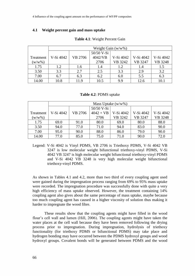
4 Influence of the coupling agent amount on the performance of WF/PP composites
66
4.1 Weight percent gain and mass uptake
Table 4.1: Weight Percent Gain
Treatment
(w/w%)
Weight Gain (w/w%)
V-Si 4042 VB 2706
50/50 V-Si
4042/VB
2706
V-Si 4042
VB 3242
V-Si 4042
VB 3247
V-Si 4042
VB 3248
1.75 1.2 1.6 1.4 1.2 1.4 1.5
3.50 3.3 2.7 2.5 3.3 2.9 3.2
7.00 6.7 6.3 6.2 6.0 5.5 6.3
14.00 10.8 11.9 10.5 9.9 12.6 10.1
Table 4.2: PDMS uptake
Treatment
(w/w%)
Mass Uptake (w/w%)
V-Si 4042 VB 2706
50/50 V-Si
4042 + VB
2706
V-Si 4042
VB 3242
V-Si 4042
VB 3247
V-Si 4042
VB 3248
1.75 69.0 91.0 80.0 69.0 80.0 88.0
3.50 94.0 77.0 71.0 94.0 83.0 90.0
7.00 95.0 90.0 88.0 86.0 79.0 90.0
14.00 77.0 85.0 75.0 71.0 90.0 72.0
Legend: V-Si 4042 is Vinyl PDMS, VB 2706 is Triethoxy PDMS, V-Si 4042 VB
3247 is low molecular weight bifunctional triethoxy-vinyl PDMS, V-Si
4042 VB 3247 is high molecular weight bifunctional triethoxy-vinyl PDMS
and V-Si 4042 VB 3248 is very high molecular weight bifunctional
triethoxy-vinyl PDMS.
As shown in Tables 4.1 and 4.2, more than two third of every coupling agent used
were gained during the impregnation process ranging from 69% to 95% mass uptake
were recorded. The impregnation procedure was successfully done with quite a very
high efficiency of mass uptake observed. However, the treatment containing 14%
coupling agent also gives about the same percentage of mass uptake, maybe because
too much coupling agent has caused in a higher viscosity of solution thus making it
harder to impregnate the wood fibre.
These results show that the coupling agents might have filled in the wood
flour’s cell wall and lumen (Hill, 2006). The coupling agents might have taken the
water places at the cell wall because they have been removed following the drying
process prior to impregnation. During impregnation, hydrolysis of triethoxy
functionality (for triethoxy PDMS or bifunctional PDMS) may take place and
hydrogen bonding may have occurred between the PDMS hydroxyl groups and wood
hydroxyl groups. Covalent bonds will be generated between PDMS and the wood
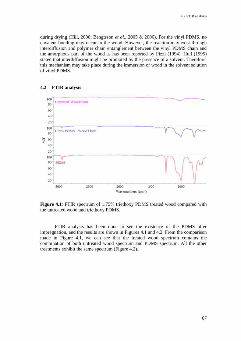
4.2 FTIR analysis
67
during drying (Hill, 2006; Bengtsson et al., 2005 & 2006). For the vinyl PDMS, no
covalent bonding may occur to the wood. However, the reaction may exist through
interdiffusion and polymer chain entanglement between the vinyl PDMS chain and
the amorphous part of the wood as has been reported by Pizzi (1994). Hull (1995)
stated that interdiffusion might be promoted by the presence of a solvent. Therefore,
this mechanism may take place during the immersion of wood in the solvent solution
of vinyl PDMS.
4.2 FTIR analysis
Figure 4.1: FTIR spectrum of 1.75% triethoxy PDMS treated wood compared with
the untreated wood and triethoxy PDMS.
FTIR analysis has been done to see the existence of the PDMS after
impregnation, and the results are shown in Figures 4.1 and 4.2. From the comparison
made in Figure 4.1, we can see that the treated wood spectrum contains the
combination of both untreated wood spectrum and PDMS spectrum. All the other
treatments exhibit the same spectrum (Figure 4.2).

4 Influence of the coupling agent amount on the performance of WF/PP composites
68
Figure 4.2: FTIR spectrum of different triethoxy PDMS treatment concentration
4.3 Moisture absorption
Figure 4.3: Moisture absorption of wood flour under ambient temperature with
1.75% of different PDMS treatment in the matter of time.
Moisture absorption test has also been done to examine the effect of PDMS
treatment on the hygroscopicity of the treated wood. The treated wood was first dried
0
2
4
6
8
10
12
0 5 10 15 20 25
Mo
istu
re C
on
ten
t (%
)
Day
No Treatment
Triethoxy
Vinyl
50/50 Mixture of Triethoxy and Vinyl
Bifunctional Low Mw
Bifunctional High Mw
Bifunctional Very High Mw
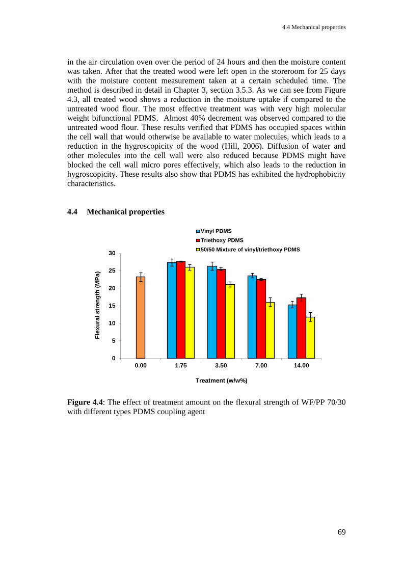
4.4 Mechanical properties
69
in the air circulation oven over the period of 24 hours and then the moisture content
was taken. After that the treated wood were left open in the storeroom for 25 days
with the moisture content measurement taken at a certain scheduled time. The
method is described in detail in Chapter 3, section 3.5.3. As we can see from Figure
4.3, all treated wood shows a reduction in the moisture uptake if compared to the
untreated wood flour. The most effective treatment was with very high molecular
weight bifunctional PDMS. Almost 40% decrement was observed compared to the
untreated wood flour. These results verified that PDMS has occupied spaces within
the cell wall that would otherwise be available to water molecules, which leads to a
reduction in the hygroscopicity of the wood (Hill, 2006). Diffusion of water and
other molecules into the cell wall were also reduced because PDMS might have
blocked the cell wall micro pores effectively, which also leads to the reduction in
hygroscopicity. These results also show that PDMS has exhibited the hydrophobicity
characteristics.
4.4 Mechanical properties
Figure 4.4: The effect of treatment amount on the flexural strength of WF/PP 70/30
with different types PDMS coupling agent
0
5
10
15
20
25
30
0.00 1.75 3.50 7.00 14.00
Fle
xu
ral s
tren
gth
(M
Pa
)
Treatment (w/w%)
Vinyl PDMS
Triethoxy PDMS
50/50 Mixture of vinyl/triethoxy PDMS
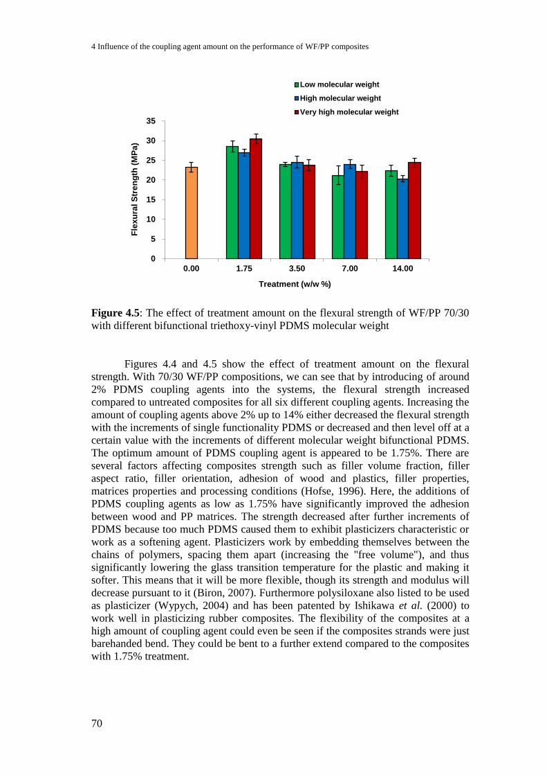
4 Influence of the coupling agent amount on the performance of WF/PP composites
70
Figure 4.5: The effect of treatment amount on the flexural strength of WF/PP 70/30
with different bifunctional triethoxy-vinyl PDMS molecular weight
Figures 4.4 and 4.5 show the effect of treatment amount on the flexural
strength. With 70/30 WF/PP compositions, we can see that by introducing of around
2% PDMS coupling agents into the systems, the flexural strength increased
compared to untreated composites for all six different coupling agents. Increasing the
amount of coupling agents above 2% up to 14% either decreased the flexural strength
with the increments of single functionality PDMS or decreased and then level off at a
certain value with the increments of different molecular weight bifunctional PDMS.
The optimum amount of PDMS coupling agent is appeared to be 1.75%. There are
several factors affecting composites strength such as filler volume fraction, filler
aspect ratio, filler orientation, adhesion of wood and plastics, filler properties,
matrices properties and processing conditions (Hofse, 1996). Here, the additions of
PDMS coupling agents as low as 1.75% have significantly improved the adhesion
between wood and PP matrices. The strength decreased after further increments of
PDMS because too much PDMS caused them to exhibit plasticizers characteristic or
work as a softening agent. Plasticizers work by embedding themselves between the
chains of polymers, spacing them apart (increasing the "free volume"), and thus
significantly lowering the glass transition temperature for the plastic and making it
softer. This means that it will be more flexible, though its strength and modulus will
decrease pursuant to it (Biron, 2007). Furthermore polysiloxane also listed to be used
as plasticizer (Wypych, 2004) and has been patented by Ishikawa et al. (2000) to
work well in plasticizing rubber composites. The flexibility of the composites at a
high amount of coupling agent could even be seen if the composites strands were just
barehanded bend. They could be bent to a further extend compared to the composites
with 1.75% treatment.
0
5
10
15
20
25
30
35
0.00 1.75 3.50 7.00 14.00
Fle
xu
ral S
tre
ng
th (
MP
a)
Treatment (w/w %)
Low molecular weight
High molecular weight
Very high molecular weight
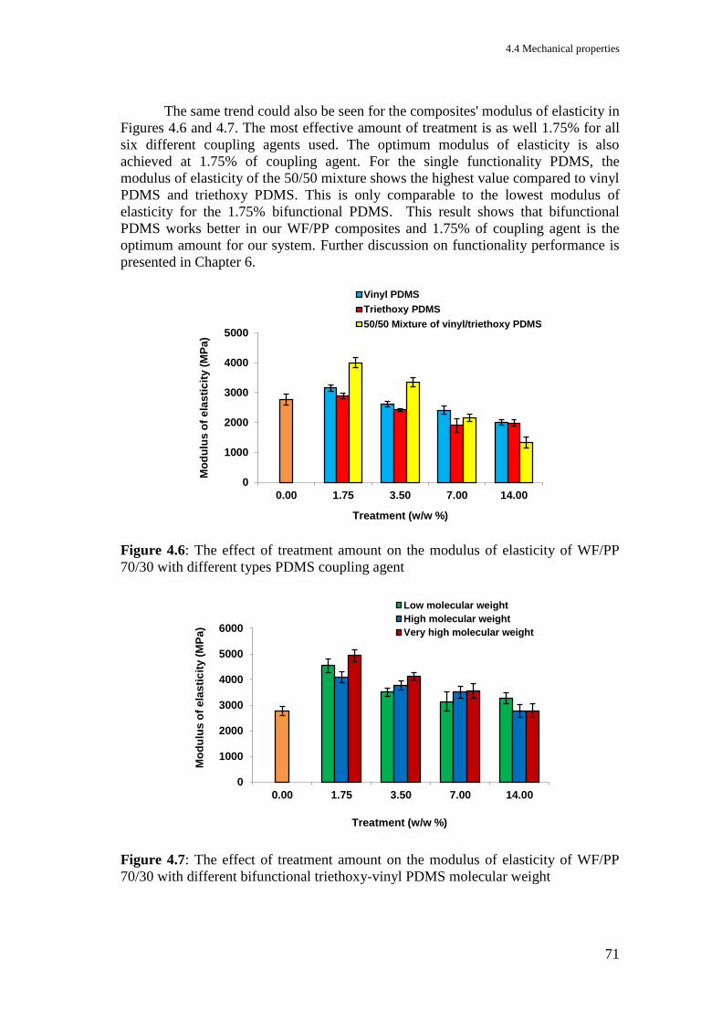
4.4 Mechanical properties
71
The same trend could also be seen for the composites' modulus of elasticity in
Figures 4.6 and 4.7. The most effective amount of treatment is as well 1.75% for all
six different coupling agents used. The optimum modulus of elasticity is also
achieved at 1.75% of coupling agent. For the single functionality PDMS, the
modulus of elasticity of the 50/50 mixture shows the highest value compared to vinyl
PDMS and triethoxy PDMS. This is only comparable to the lowest modulus of
elasticity for the 1.75% bifunctional PDMS. This result shows that bifunctional
PDMS works better in our WF/PP composites and 1.75% of coupling agent is the
optimum amount for our system. Further discussion on functionality performance is
presented in Chapter 6.
Figure 4.6: The effect of treatment amount on the modulus of elasticity of WF/PP
70/30 with different types PDMS coupling agent
Figure 4.7: The effect of treatment amount on the modulus of elasticity of WF/PP
70/30 with different bifunctional triethoxy-vinyl PDMS molecular weight
0
1000
2000
3000
4000
5000
0.00 1.75 3.50 7.00 14.00
Mo
du
lus
of
ela
sti
cit
y (
MP
a)
Treatment (w/w %)
Vinyl PDMS
Triethoxy PDMS
50/50 Mixture of vinyl/triethoxy PDMS
0
1000
2000
3000
4000
5000
6000
0.00 1.75 3.50 7.00 14.00
Mo
du
lus
of
ela
sti
cit
y (
MP
a)
Treatment (w/w %)
Low molecular weight
High molecular weight
Very high molecular weight
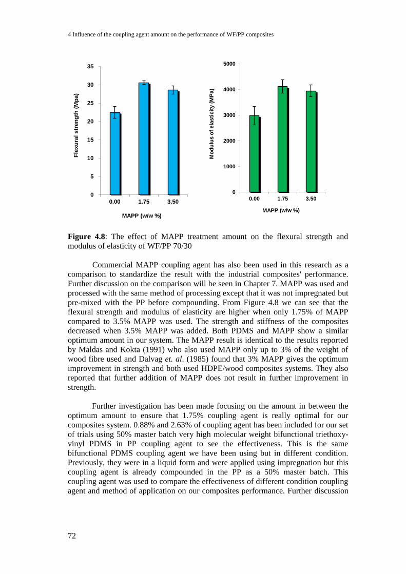
4 Influence of the coupling agent amount on the performance of WF/PP composites
72
Figure 4.8: The effect of MAPP treatment amount on the flexural strength and
modulus of elasticity of WF/PP 70/30
Commercial MAPP coupling agent has also been used in this research as a
comparison to standardize the result with the industrial composites' performance.
Further discussion on the comparison will be seen in Chapter 7. MAPP was used and
processed with the same method of processing except that it was not impregnated but
pre-mixed with the PP before compounding. From Figure 4.8 we can see that the
flexural strength and modulus of elasticity are higher when only 1.75% of MAPP
compared to 3.5% MAPP was used. The strength and stiffness of the composites
decreased when 3.5% MAPP was added. Both PDMS and MAPP show a similar
optimum amount in our system. The MAPP result is identical to the results reported
by Maldas and Kokta (1991) who also used MAPP only up to 3% of the weight of
wood fibre used and Dalvag et. al. (1985) found that 3% MAPP gives the optimum
improvement in strength and both used HDPE/wood composites systems. They also
reported that further addition of MAPP does not result in further improvement in
strength.
Further investigation has been made focusing on the amount in between the
optimum amount to ensure that 1.75% coupling agent is really optimal for our
composites system. 0.88% and 2.63% of coupling agent has been included for our set
of trials using 50% master batch very high molecular weight bifunctional triethoxy-
vinyl PDMS in PP coupling agent to see the effectiveness. This is the same
bifunctional PDMS coupling agent we have been using but in different condition.
Previously, they were in a liquid form and were applied using impregnation but this
coupling agent is already compounded in the PP as a 50% master batch. This
coupling agent was used to compare the effectiveness of different condition coupling
agent and method of application on our composites performance. Further discussion
0
5
10
15
20
25
30
35
0.00 1.75 3.50
Fle
xu
ral
str
en
gth
(M
pa)
MAPP (w/w %)
0
1000
2000
3000
4000
5000
0.00 1.75 3.50
Mo
du
lus
of
ela
sti
cit
y (
MP
a)
MAPP (w/w %)
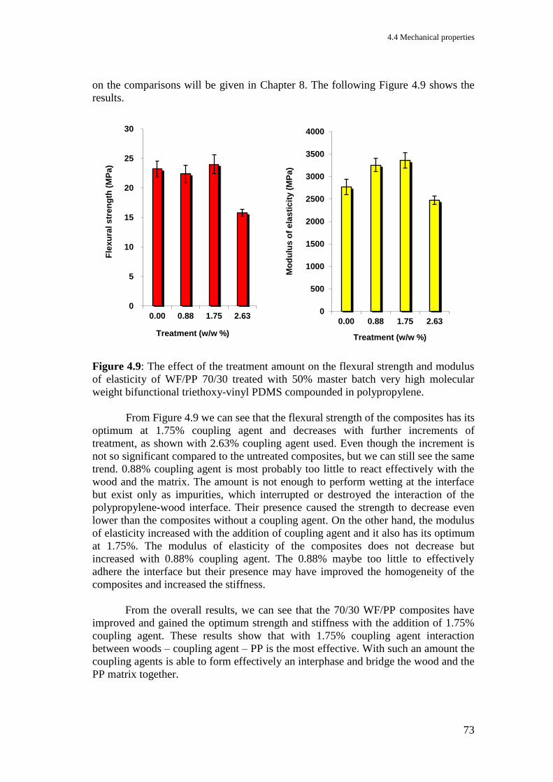
4.4 Mechanical properties
73
on the comparisons will be given in Chapter 8. The following Figure 4.9 shows the
results.
Figure 4.9: The effect of the treatment amount on the flexural strength and modulus
of elasticity of WF/PP 70/30 treated with 50% master batch very high molecular
weight bifunctional triethoxy-vinyl PDMS compounded in polypropylene.
From Figure 4.9 we can see that the flexural strength of the composites has its
optimum at 1.75% coupling agent and decreases with further increments of
treatment, as shown with 2.63% coupling agent used. Even though the increment is
not so significant compared to the untreated composites, but we can still see the same
trend. 0.88% coupling agent is most probably too little to react effectively with the
wood and the matrix. The amount is not enough to perform wetting at the interface
but exist only as impurities, which interrupted or destroyed the interaction of the
polypropylene-wood interface. Their presence caused the strength to decrease even
lower than the composites without a coupling agent. On the other hand, the modulus
of elasticity increased with the addition of coupling agent and it also has its optimum
at 1.75%. The modulus of elasticity of the composites does not decrease but
increased with 0.88% coupling agent. The 0.88% maybe too little to effectively
adhere the interface but their presence may have improved the homogeneity of the
composites and increased the stiffness.
From the overall results, we can see that the 70/30 WF/PP composites have
improved and gained the optimum strength and stiffness with the addition of 1.75%
coupling agent. These results show that with 1.75% coupling agent interaction
between woods – coupling agent – PP is the most effective. With such an amount the
coupling agents is able to form effectively an interphase and bridge the wood and the
PP matrix together.
0
5
10
15
20
25
30
0.00 0.88 1.75 2.63
Fle
xu
ral s
tre
ng
th (
MP
a)
Treatment (w/w %)
0
500
1000
1500
2000
2500
3000
3500
4000
0.00 0.88 1.75 2.63
Mo
du
lus
of
ela
sti
cit
y (
MP
a)
Treatment (w/w %)
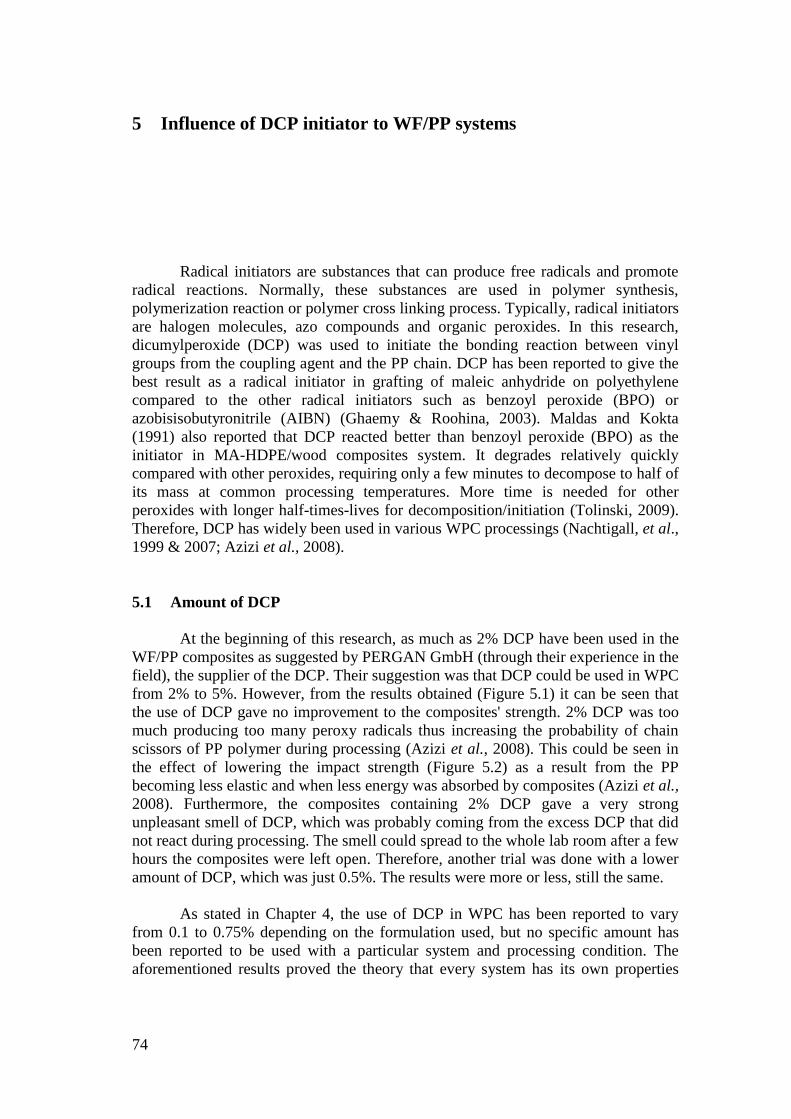
74
5 Influence of DCP initiator to WF/PP systems
Radical initiators are substances that can produce free radicals and promote
radical reactions. Normally, these substances are used in polymer synthesis,
polymerization reaction or polymer cross linking process. Typically, radical initiators
are halogen molecules, azo compounds and organic peroxides. In this research,
dicumylperoxide (DCP) was used to initiate the bonding reaction between vinyl
groups from the coupling agent and the PP chain. DCP has been reported to give the
best result as a radical initiator in grafting of maleic anhydride on polyethylene
compared to the other radical initiators such as benzoyl peroxide (BPO) or
azobisisobutyronitrile (AIBN) (Ghaemy & Roohina, 2003). Maldas and Kokta
(1991) also reported that DCP reacted better than benzoyl peroxide (BPO) as the
initiator in MA-HDPE/wood composites system. It degrades relatively quickly
compared with other peroxides, requiring only a few minutes to decompose to half of
its mass at common processing temperatures. More time is needed for other
peroxides with longer half-times-lives for decomposition/initiation (Tolinski, 2009).
Therefore, DCP has widely been used in various WPC processings (Nachtigall, et al.,
1999 & 2007; Azizi et al., 2008).
5.1 Amount of DCP
At the beginning of this research, as much as 2% DCP have been used in the
WF/PP composites as suggested by PERGAN GmbH (through their experience in the
field), the supplier of the DCP. Their suggestion was that DCP could be used in WPC
from 2% to 5%. However, from the results obtained (Figure 5.1) it can be seen that
the use of DCP gave no improvement to the composites' strength. 2% DCP was too
much producing too many peroxy radicals thus increasing the probability of chain
scissors of PP polymer during processing (Azizi et al., 2008). This could be seen in
the effect of lowering the impact strength (Figure 5.2) as a result from the PP
becoming less elastic and when less energy was absorbed by composites (Azizi et al.,
2008). Furthermore, the composites containing 2% DCP gave a very strong
unpleasant smell of DCP, which was probably coming from the excess DCP that did
not react during processing. The smell could spread to the whole lab room after a few
hours the composites were left open. Therefore, another trial was done with a lower
amount of DCP, which was just 0.5%. The results were more or less, still the same.
As stated in Chapter 4, the use of DCP in WPC has been reported to vary
from 0.1 to 0.75% depending on the formulation used, but no specific amount has
been reported to be used with a particular system and processing condition. The
aforementioned results proved the theory that every system has its own properties
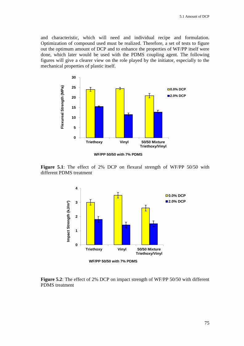
5.1 Amount of DCP
75
and characteristic, which will need and individual recipe and formulation.
Optimization of compound used must be realized. Therefore, a set of tests to figure
out the optimum amount of DCP and to enhance the properties of WF/PP itself were
done, which later would be used with the PDMS coupling agent. The following
figures will give a clearer view on the role played by the initiator, especially to the
mechanical properties of plastic itself.
Figure 5.1: The effect of 2% DCP on flexural strength of WF/PP 50/50 with
different PDMS treatment
Figure 5.2: The effect of 2% DCP on impact strength of WF/PP 50/50 with different
PDMS treatment
0
5
10
15
20
25
30
Triethoxy Vinyl 50/50 MixtureTriethoxy/Vinyl
Fle
xu
rea
l S
tre
ng
th (
MP
a)
WF/PP 50/50 with 7% PDMS
0.0% DCP
2.0% DCP
0
1
2
3
4
Triethoxy Vinyl 50/50 MixtureTriethoxy/Vinyl
Imp
ac
t S
tren
gth
(k
J/m
²)
WF/PP 50/50 with 7% PDMS
0.0% DCP
2.0% DCP
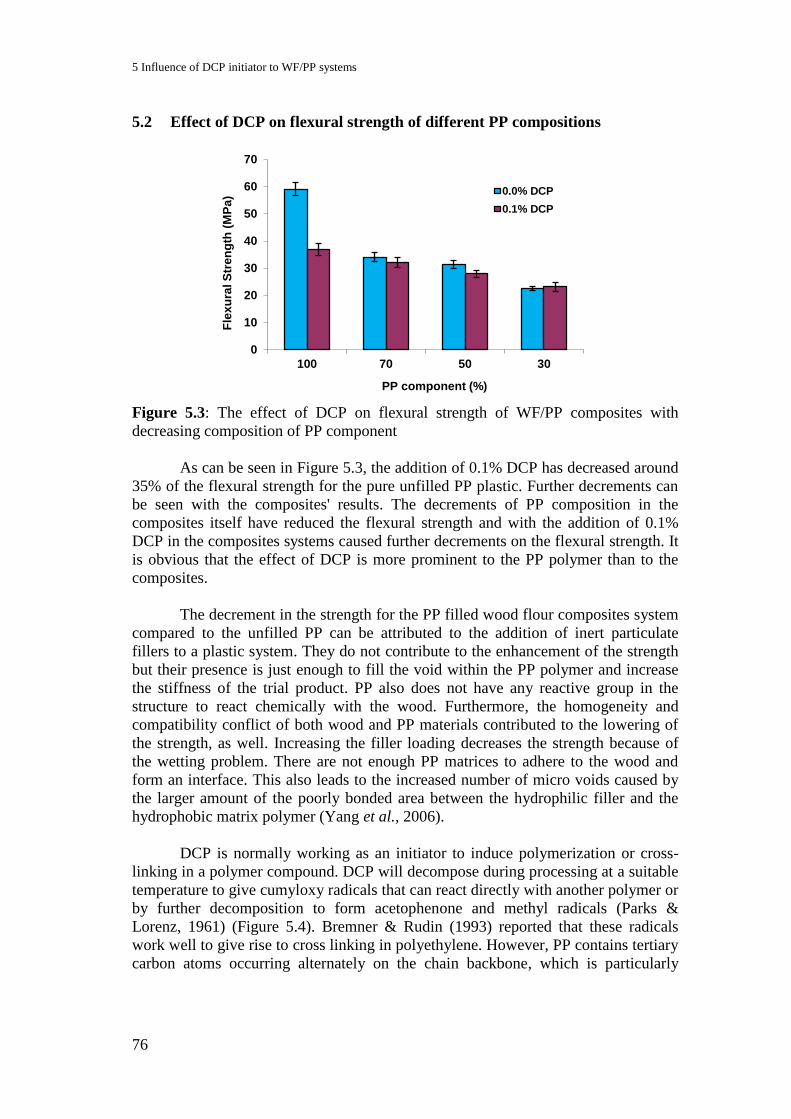
5 Influence of DCP initiator to WF/PP systems
76
5.2 Effect of DCP on flexural strength of different PP compositions
Figure 5.3: The effect of DCP on flexural strength of WF/PP composites with
decreasing composition of PP component
As can be seen in Figure 5.3, the addition of 0.1% DCP has decreased around
35% of the flexural strength for the pure unfilled PP plastic. Further decrements can
be seen with the composites' results. The decrements of PP composition in the
composites itself have reduced the flexural strength and with the addition of 0.1%
DCP in the composites systems caused further decrements on the flexural strength. It
is obvious that the effect of DCP is more prominent to the PP polymer than to the
composites.
The decrement in the strength for the PP filled wood flour composites system
compared to the unfilled PP can be attributed to the addition of inert particulate
fillers to a plastic system. They do not contribute to the enhancement of the strength
but their presence is just enough to fill the void within the PP polymer and increase
the stiffness of the trial product. PP also does not have any reactive group in the
structure to react chemically with the wood. Furthermore, the homogeneity and
compatibility conflict of both wood and PP materials contributed to the lowering of
the strength, as well. Increasing the filler loading decreases the strength because of
the wetting problem. There are not enough PP matrices to adhere to the wood and
form an interface. This also leads to the increased number of micro voids caused by
the larger amount of the poorly bonded area between the hydrophilic filler and the
hydrophobic matrix polymer (Yang et al., 2006).
DCP is normally working as an initiator to induce polymerization or cross-
linking in a polymer compound. DCP will decompose during processing at a suitable
temperature to give cumyloxy radicals that can react directly with another polymer or
by further decomposition to form acetophenone and methyl radicals (Parks &
Lorenz, 1961) (Figure 5.4). Bremner & Rudin (1993) reported that these radicals
work well to give rise to cross linking in polyethylene. However, PP contains tertiary
carbon atoms occurring alternately on the chain backbone, which is particularly
0
10
20
30
40
50
60
70
100 70 50 30
Fle
xu
ral S
tre
ng
th (
MP
a)
PP component (%)
0.0% DCP
0.1% DCP
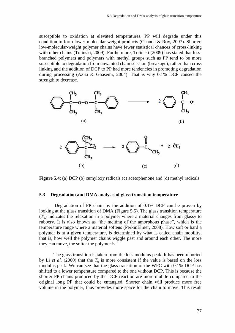
5.3 Degradation and DMA analysis of glass transition temperature
77
susceptible to oxidation at elevated temperatures. PP will degrade under this
condition to form lower-molecular-weight products (Chanda & Roy, 2007). Shorter,
low-molecular-weight polymer chains have fewer statistical chances of cross-linking
with other chains (Tolinski, 2009). Furthermore, Tolinski (2009) has stated that less-
branched polymers and polymers with methyl groups such as PP tend to be more
susceptible to degradation from unwanted chain scission (breakage), rather than cross
linking and the addition of DCP to PP had more tendencies in promoting degradation
during processing (Azizi & Ghasemi, 2004). That is why 0.1% DCP caused the
strength to decrease.
Figure 5.4: (a) DCP (b) cumyloxy radicals (c) acetophenone and (d) methyl radicals
5.3 Degradation and DMA analysis of glass transition temperature
Degradation of PP chain by the addition of 0.1% DCP can be proven by
looking at the glass transition of DMA (Figure 5.5). The glass transition temperature
(Tg) indicates the relaxation in a polymer where a material changes from glassy to
rubbery. It is also known as “the melting of the amorphous phase”, which is the
temperature range where a material softens (PerkinElmer, 2008). How soft or hard a
polymer is at a given temperature, is determined by what is called chain mobility,
that is, how well the polymer chains wiggle past and around each other. The more
they can move, the softer the polymer is.
The glass transition is taken from the loss modulus peak. It has been reported
by Li et al. (2000) that the Tg is more consistent if the value is based on the loss
modulus peak. We can see that the glass transition of the WPC with 0.1% DCP has
shifted to a lower temperature compared to the one without DCP. This is because the
shorter PP chains produced by the DCP reaction are more mobile compared to the
original long PP that could be entangled. Shorter chain will produce more free
volume in the polymer, thus provides more space for the chain to move. This result
(a) (b)
(b) (c) (d)
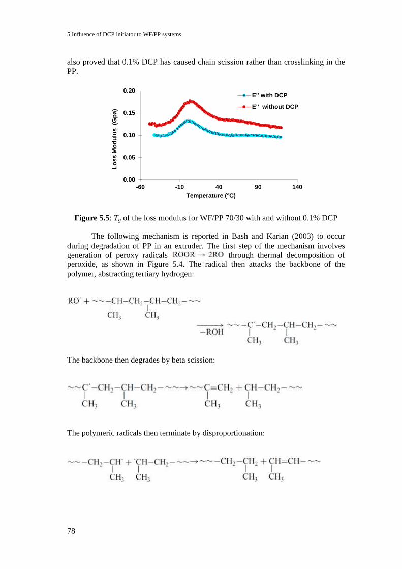
5 Influence of DCP initiator to WF/PP systems
78
also proved that 0.1% DCP has caused chain scission rather than crosslinking in the
PP.
Figure 5.5: Tg of the loss modulus for WF/PP 70/30 with and without 0.1% DCP
The following mechanism is reported in Bash and Karian (2003) to occur
during degradation of PP in an extruder. The first step of the mechanism involves
generation of peroxy radicals through thermal decomposition of
peroxide, as shown in Figure 5.4. The radical then attacks the backbone of the
polymer, abstracting tertiary hydrogen:
The backbone then degrades by beta scission:
The polymeric radicals then terminate by disproportionation:
0.00
0.05
0.10
0.15
0.20
-60 -10 40 90 140
Lo
ss
Mo
du
lus
(G
pa
)
Temperature (°C)
E'' with DCP
E'' without DCP

5.4 Effect of DCP on Modulus of elasticity and impact strength with different PP compositions
79
5.4 Effect of DCP on Modulus of elasticity and impact strength with different
PP compositions
Figure 5.6: The effect of DCP on modulus of elasticity of WF/PP composites with
decreasing composition of PP component
As discussed, the stiffness of the composites would be higher than the
unfilled PP plastic, a normal phenomenon when a matrix is filled with inert filler.
Adding of 0.1% DCP to the unfilled PP and composites with 30% wood caused some
increment in the modulus of elasticity while the effect to the composites with 50%
and 70% wood flour is lowering the modulus of elasticity. The increment in the
modulus of elasticity of unfilled PP and composites with high PP content is due to
the higher crystallization as results of chain scission (Maier & Calafut, 1998). It is
easier to form crystal with shorter chain length (Azizi & Ghasemi, 2004; Maier &
Calafut, 1998). However, the crystallization effect cannot be seen when more wood
was used in the composites system.
Impact strength depends directly on the molecular weight of the polymer
(Ibhadon, 1998). Thermal degradation or chain scission generally involves changes
in the molecular weight or molecular weight distributions. The effect of lower
molecular weight on the impact strength can clearly be seen in Figure 5.7. The
impact strength of the unfilled PP is obviously decreased when 0.1% DCP was
added, showing the effect of chain scission on PP plastic. The decrement of impact
strength is also observed in the composites. This is due to the lower elasticity and
lacked in interconnection in the composites to absorb energy, following shorter PP
chain length with the addition of DCP.
0
500
1000
1500
2000
2500
3000
3500
4000
100 70 50 30
Mo
du
lus
of
Ela
sti
cit
y (
MP
a)
PP component (%)
0.0% DCP
0.1% DCP

5 Influence of DCP initiator to WF/PP systems
80
Figure 5.7: The effect of DCP on impact strength of WF/PP composites with
decreasing composition of PP component
5.5 DCP contents with different WF/PP compositions
Figure 5.8: The effect of DCP on flexural strength of WF/PP composites with three
different compositions
0
2
4
6
8
10
12
14
100 70 50 30
Imp
ac
t S
tre
ng
th (
kJ
/m2)
PP component (%)
0.0% DCP
0.1% DCP
0
5
10
15
20
25
30
35
40
70/30 50/50 30/70
Fle
xu
ral S
tren
gth
(M
Pa
)
WF/PP composition (%)
0.0% DCP
0.1% DCP
0.2% DCP

5.5 DCP contents with different WF/PP compositions
81
Figure 5.9: The effect of DCP on modulus of elasticity of WF/PP composites with
three different compositions
Figure 5.10: The effect of DCP on impact strength of WF/PP composites with three
different compositions
Figures 5.8 to 5.10 give the comparisons when more DCP was used in three
different WF/PP composites systems. Increasing DCP content to 0.2% has decreased
the strength of composites containing 70% PP but increased with composites
containing lower PP content. These results show that the existence of more free
radicals during processing caused more chain scission in PP and the effect is more
significant when more PP plastic compounded in the composites. These results can
0
500
1000
1500
2000
2500
3000
3500
4000
4500
70/30 50/50 30/70
Mo
du
lus
of
ela
sti
cit
y (
MP
a)
WF/PP composition (%)
0.0% DCP
0.1% DCP
0.2% DCP
0
1
2
3
4
5
70/30 50/50 30/70
Imp
ac
t S
tren
gth
(k
J/m
²)
WF/PP composition (%)
0.0% DCP
0.1% DCP
0.2% DCP
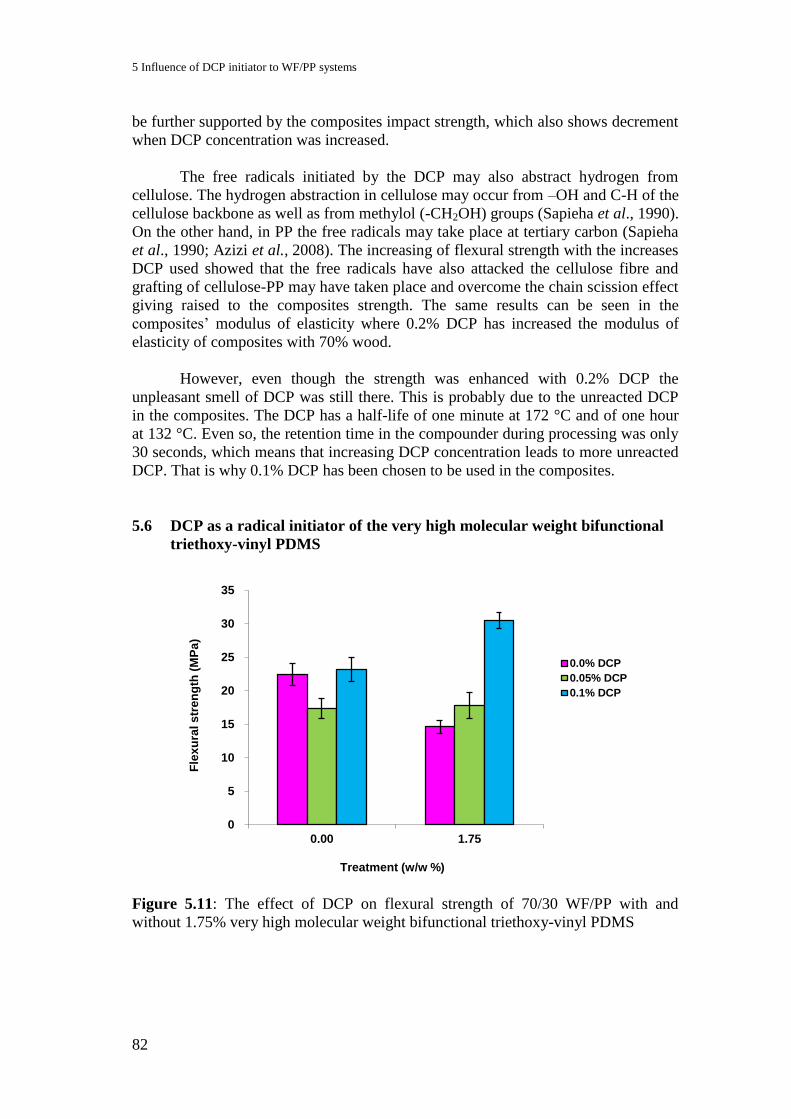
5 Influence of DCP initiator to WF/PP systems
82
be further supported by the composites impact strength, which also shows decrement
when DCP concentration was increased.
The free radicals initiated by the DCP may also abstract hydrogen from
cellulose. The hydrogen abstraction in cellulose may occur from –OH and C-H of the
cellulose backbone as well as from methylol (-CH2OH) groups (Sapieha et al., 1990).
On the other hand, in PP the free radicals may take place at tertiary carbon (Sapieha
et al., 1990; Azizi et al., 2008). The increasing of flexural strength with the increases
DCP used showed that the free radicals have also attacked the cellulose fibre and
grafting of cellulose-PP may have taken place and overcome the chain scission effect
giving raised to the composites strength. The same results can be seen in the
composites’ modulus of elasticity where 0.2% DCP has increased the modulus of
elasticity of composites with 70% wood.
However, even though the strength was enhanced with 0.2% DCP the
unpleasant smell of DCP was still there. This is probably due to the unreacted DCP
in the composites. The DCP has a half-life of one minute at 172 °C and of one hour
at 132 °C. Even so, the retention time in the compounder during processing was only
30 seconds, which means that increasing DCP concentration leads to more unreacted
DCP. That is why 0.1% DCP has been chosen to be used in the composites.
5.6 DCP as a radical initiator of the very high molecular weight bifunctional
triethoxy-vinyl PDMS
Figure 5.11: The effect of DCP on flexural strength of 70/30 WF/PP with and
without 1.75% very high molecular weight bifunctional triethoxy-vinyl PDMS
0
5
10
15
20
25
30
35
0.00 1.75
Fle
xu
ral s
tren
gth
(M
Pa
)
Treatment (w/w %)
0.0% DCP
0.05% DCP
0.1% DCP
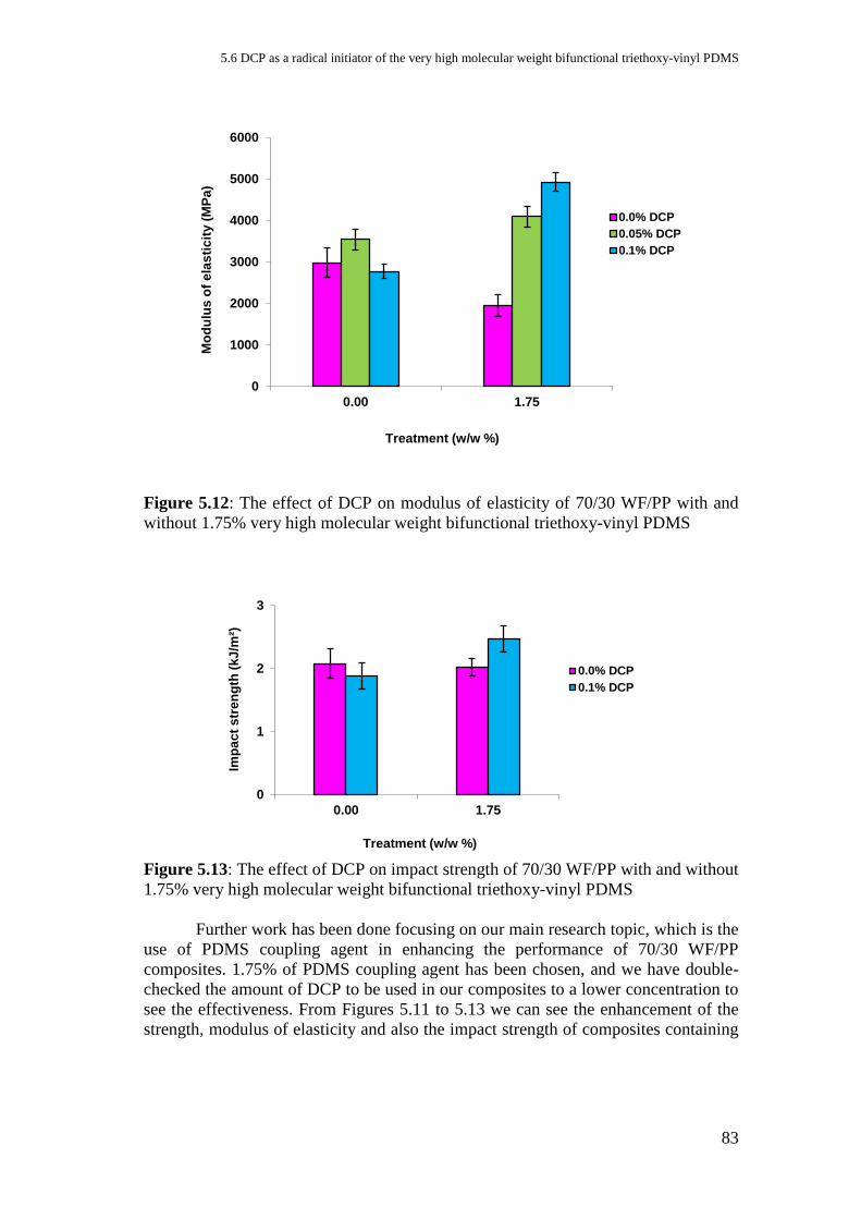
5.6 DCP as a radical initiator of the very high molecular weight bifunctional triethoxy-vinyl PDMS
83
Figure 5.12: The effect of DCP on modulus of elasticity of 70/30 WF/PP with and
without 1.75% very high molecular weight bifunctional triethoxy-vinyl PDMS
Figure 5.13: The effect of DCP on impact strength of 70/30 WF/PP with and without
1.75% very high molecular weight bifunctional triethoxy-vinyl PDMS
Further work has been done focusing on our main research topic, which is the
use of PDMS coupling agent in enhancing the performance of 70/30 WF/PP
composites. 1.75% of PDMS coupling agent has been chosen, and we have double-
checked the amount of DCP to be used in our composites to a lower concentration to
see the effectiveness. From Figures 5.11 to 5.13 we can see the enhancement of the
strength, modulus of elasticity and also the impact strength of composites containing
0
1000
2000
3000
4000
5000
6000
0.00 1.75
Mo
du
lus
of
ela
sti
cit
y (
MP
a)
Treatment (w/w %)
0.0% DCP
0.05% DCP
0.1% DCP
0
1
2
3
0.00 1.75
Imp
ac
t s
tren
gth
(k
J/m
²)
Treatment (w/w %)
0.0% DCP
0.1% DCP
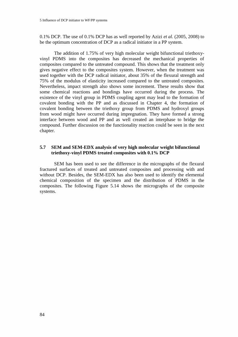
5 Influence of DCP initiator to WF/PP systems
84
0.1% DCP. The use of 0.1% DCP has as well reported by Azizi et al. (2005, 2008) to
be the optimum concentration of DCP as a radical initiator in a PP system.
The addition of 1.75% of very high molecular weight bifunctional triethoxy-
vinyl PDMS into the composites has decreased the mechanical properties of
composites compared to the untreated compound. This shows that the treatment only
gives negative effect to the composites system. However, when the treatment was
used together with the DCP radical initiator, about 35% of the flexural strength and
75% of the modulus of elasticity increased compared to the untreated composites.
Nevertheless, impact strength also shows some increment. These results show that
some chemical reactions and bondings have occurred during the process. The
existence of the vinyl group in PDMS coupling agent may lead to the formation of
covalent bonding with the PP and as discussed in Chapter 4, the formation of
covalent bonding between the triethoxy group from PDMS and hydroxyl groups
from wood might have occurred during impregnation. They have formed a strong
interface between wood and PP and as well created an interphase to bridge the
compound. Further discussion on the functionality reaction could be seen in the next
chapter.
5.7 SEM and SEM-EDX analysis of very high molecular weight bifunctional
triethoxy-vinyl PDMS treated composites with 0.1% DCP
SEM has been used to see the difference in the micrographs of the flexural
fractured surfaces of treated and untreated composites and processing with and
without DCP. Besides, the SEM-EDX has also been used to identify the elemental
chemical composition of the specimen and the distribution of PDMS in the
composites. The following Figure 5.14 shows the micrographs of the composite
systems.
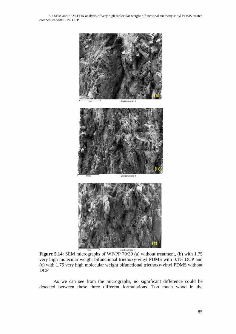
5.7 SEM and SEM-EDX analysis of very high molecular weight bifunctional triethoxy-vinyl PDMS treated
composites with 0.1% DCP
85
Figure 5.14: SEM micrographs of WF/PP 70/30 (a) without treatment, (b) with 1.75
very high molecular weight bifunctional triethoxy-vinyl PDMS with 0.1% DCP and
(c) with 1.75 very high molecular weight bifunctional triethoxy-vinyl PDMS without
DCP
As we can see from the micrographs, no significant difference could be
detected between these three different formulations. Too much wood in the
(a)
(b)
(c)

5 Influence of DCP initiator to WF/PP systems
86
composites caused difficulties even to distinguish between wood and PP polymer
matrices. Following these results we have made another attempt by polishing the
cross section of the specimen. However, this effort did not bring any success either.
We still cannot recognize any differences from the micrograph as shown in the
following Figure 5.15.
(a) (b)
Figure 5.15: SEM micrographs of WF/PP 70/30 (a) without treatment and (b) with
1.75% very high molecular weight bifunctional triethoxy-vinyl PDMS and 0.1%
DCP
60
80
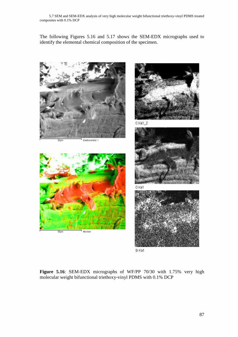
5.7 SEM and SEM-EDX analysis of very high molecular weight bifunctional triethoxy-vinyl PDMS treated
composites with 0.1% DCP
87
The following Figures 5.16 and 5.17 shows the SEM-EDX micrographs used to
identify the elemental chemical composition of the specimen.
Figure 5.16: SEM-EDX micrographs of WF/PP 70/30 with 1.75% very high
molecular weight bifunctional triethoxy-vinyl PDMS with 0.1% DCP

5 Influence of DCP initiator to WF/PP systems
88
Figure 5.17: SEM-EDX images of WF/PP 70/30 with 1.75% very high molecular
weight bifunctional triethoxy-vinyl PDMS without DCP
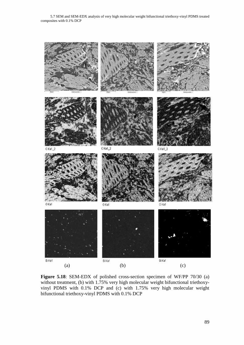
5.7 SEM and SEM-EDX analysis of very high molecular weight bifunctional triethoxy-vinyl PDMS treated
composites with 0.1% DCP
89
(a) (b) (c)
Figure 5.18: SEM-EDX of polished cross-section specimen of WF/PP 70/30 (a)
without treatment, (b) with 1.75% very high molecular weight bifunctional triethoxy-
vinyl PDMS with 0.1% DCP and (c) with 1.75% very high molecular weight
bifunctional triethoxy-vinyl PDMS with 0.1% DCP
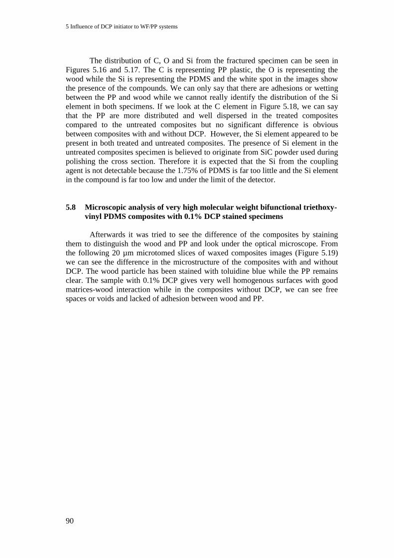
5 Influence of DCP initiator to WF/PP systems
90
The distribution of C, O and Si from the fractured specimen can be seen in
Figures 5.16 and 5.17. The C is representing PP plastic, the O is representing the
wood while the Si is representing the PDMS and the white spot in the images show
the presence of the compounds. We can only say that there are adhesions or wetting
between the PP and wood while we cannot really identify the distribution of the Si
element in both specimens. If we look at the C element in Figure 5.18, we can say
that the PP are more distributed and well dispersed in the treated composites
compared to the untreated composites but no significant difference is obvious
between composites with and without DCP. However, the Si element appeared to be
present in both treated and untreated composites. The presence of Si element in the
untreated composites specimen is believed to originate from SiC powder used during
polishing the cross section. Therefore it is expected that the Si from the coupling
agent is not detectable because the 1.75% of PDMS is far too little and the Si element
in the compound is far too low and under the limit of the detector.
5.8 Microscopic analysis of very high molecular weight bifunctional triethoxy-
vinyl PDMS composites with 0.1% DCP stained specimens
Afterwards it was tried to see the difference of the composites by staining
them to distinguish the wood and PP and look under the optical microscope. From
the following 20 µm microtomed slices of waxed composites images (Figure 5.19)
we can see the difference in the microstructure of the composites with and without
DCP. The wood particle has been stained with toluidine blue while the PP remains
clear. The sample with 0.1% DCP gives very well homogenous surfaces with good
matrices-wood interaction while in the composites without DCP, we can see free
spaces or voids and lacked of adhesion between wood and PP.
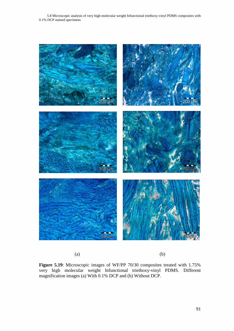
5.8 Microscopic analysis of very high molecular weight bifunctional triethoxy-vinyl PDMS composites with
0.1% DCP stained specimens
91
(a) (b)
Figure 5.19: Microscopic images of WF/PP 70/30 composites treated with 1.75%
very high molecular weight bifunctional triethoxy-vinyl PDMS. Different
magnification images (a) With 0.1% DCP and (b) Without DCP.

5 Influence of DCP initiator to WF/PP systems
92
5.9 Effect of DCP and very high molecular weight bifunctional triethoxy-vinyl
PDMS treatment on water absorption
Figure 5.20: Influence of DCP on the water absorption of 70/30 WF/PP composites
treated with 1.75% very high molecular weight bifunctional triethoxy-vinyl PDMS
Figure 5.21: Influence of DCP on the volume of 70/30 WF/PP composites treated
with 1.75% very high molecular weight bifunctional triethoxy-vinyl PDMS
The water absorption also gives better results with 1.75% very high
molecular weight bifunctional triethoxy-vinyl PDMS treated composites processed
with 0.1% DCP. Almost 45% lower water uptake was observed after 28 days of
immersion. These results support the assumption that better interface has existed in
the composites when DCP was used during processing.
0
5
10
15
20
25
30
35
40
45
0 5 10 15 20 25 30
Wa
ter
Up
tak
e (
wt%
)
Length of immersion (day)
with 0.1% DCP
without DCP
0
2
4
6
8
10
12
14
16
0 5 10 15 20 25 30
Vo
lum
e c
ha
ng
e (
%)
Length of immersion (day)
with 0.1% DCP
without DCP
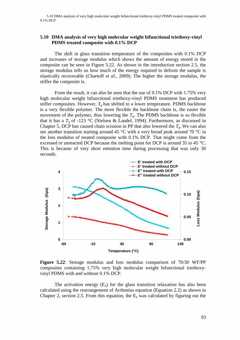
5.10 DMA analysis of very high molecular weight bifunctional triethoxy-vinyl PDMS treated composite with
0.1% DCP
93
5.10 DMA analysis of very high molecular weight bifunctional triethoxy-vinyl
PDMS treated composite with 0.1% DCP
The shift in glass transition temperature of the composites with 0.1% DCP
and increases of storage modulus which shows the amount of energy stored in the
composite can be seen in Figure 5.22. As shown in the introduction section 2.5, the
storage modulus tells us how much of the energy required to deform the sample is
elastically recoverable (Chartoff et al., 2009). The higher the storage modulus, the
stiffer the composite is.
From the result, it can also be seen that the use of 0.1% DCP with 1.75% very
high molecular weight bifunctional triethoxy-vinyl PDMS treatment has produced
stiffer composites. However, Tg has shifted to a lower temperature. PDMS backbone
is a very flexible polymer. The more flexible the backbone chain is, the easier the
movement of the polymer, thus lowering the Tg. The PDMS backbone is so flexible
that it has a Tg of -123 °C (Nielsen & Landel, 1994). Furthermore, as discussed in
Chapter 5, DCP has caused chain scission in PP that also lowered the Tg. We can also
see another transition starting around 45 °C with a very broad peak around 70 °C in
the loss modulus of treated composite with 0.1% DCP. That might come from the
excessed or unreacted DCP because the melting point for DCP is around 35 to 45 °C.
This is because of very short retention time during processing that was only 30
seconds.
Figure 5.22: Storage modulus and loss modulus comparison of 70/30 WF/PP
composites containing 1.75% very high molecular weight bifunctional triethoxy-
vinyl PDMS with and without 0.1% DCP.
The activation energy (Ea) for the glass transition relaxation has also been
calculated using the rearrangement of Arrhenius equation (Equation 2.2) as shown in
Chapter 2, section 2.5. From this equation, the Ea was calculated by figuring out the
0.00
0.05
0.10
0.15
0
1
2
3
4
-60 -10 40 90 140
Lo
ss
Mo
du
lus
(G
pa
)
Sto
rag
e M
od
ulu
s
(Gp
a)
Temperature (°C)
E' treated with DCP
E' treated without DCP
E'' treated with DCP
E'' treated without DCP
5 Influence of DCP initiator to WF/PP systems
94
maximum temperatures of the tan delta at the different frequency as shown in Figure
5.23 and give a straight line of ln f versus 1/T from the Arrhenius-plot of the
composites as shown in Figure 5.26. Ea is calculated from the slope of the plotted
line multiply to the gas constant. Figure 5.25 shows the different in tan delta peak of
different composite formulations at one Hz of frequency.
Figure 5.23: Tan delta peak of WF/PP 70/30 with 1.75% very high molecular weight
bifunctional triethoxy-vinyl PDMS with 0.1% DCP at different frequency.
It has been reported that increasing of the test frequency or heating rate leads
to a shift of Tg to a higher temperature (Chartoff et al. in Li et al., 2000). From the
above result (Figure 5.23), it can be seen that the increase of the Tg depends on the
frequency. At a very low frequency that is 0.1 Hz a sharp transition peak around 40
°C can be seen. This is due to the crystalline loss peak of inter or intracrystalline
motion origin of PP. This transition, also known as Tα*, occur in semi crystalline
polymers when the crystals slipped from their original origin. This transition only
appeared with 1 Hz of frequency because at higher frequency the transition is shifted
to a higher temperature. The same loss peak can be seen in the tan delta plot of the
neat PP at the same 0.1 Hz frequency (Figure 5.24), which was also reported by
Jarrigeon et al. (1980). Normally three transitions can occur in isotactic PP: the glass
transition (Tg) could occur at a temperature range from -40 °C to 20 °C but
commonly occur around 0 °C, α transition of crystalline part in PP (Tα*) which also
can occur in a very broad temperature ranging from around 40 °C to more than 100
°C and the melting (Tm) normally occur at 165 °C to 175 °C. (Jarrigeon et al., 1980;
Beck et al., 1963; Patnaik, 2004).
0.00
0.05
0.10
0.15
0.20
-60 -10 40 90
Tan
Delt
a
Temperature (°C)
0.1 Hz
1 Hz
10 Hz

5.10 DMA analysis of very high molecular weight bifunctional triethoxy-vinyl PDMS treated composite with
0.1% DCP
95
Figure 5.24: Loss peak in the PP tan delta plot at different frequency
Figure 5.25: Tan delta peak comparison of WF/PP 70/30 with 1.75% very high
molecular weight bifunctional triethoxy-vinyl PDMS with and without 0.1% DCP
and untreated WF/PP 70/30 without DCP at 1Hz of frequency.
0.00
0.05
0.10
0.15
-60 -10 40 90
Ta
n D
elt
a
Temperature (°C)
0.1Hz
1Hz
10Hz
0.00
0.05
0.10
0.15
0.20
-60 -10 40 90
Tan
Delt
a
Temperature (°C)
treated with 0.1% DCP
treated without DCP
untreated without DCP
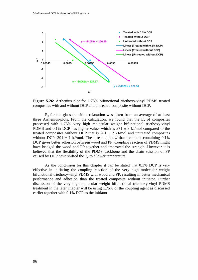
5 Influence of DCP initiator to WF/PP systems
96
Figure 5.26: Arrhenius plot for 1.75% bifunctional triethoxy-vinyl PDMS treated
composites with and without DCP and untreated composite without DCP.
Ea for the glass transition relaxation was taken from an average of at least
three Arrhenius-plots. From the calculation, we found that the Ea of composites
processed with 1.75% very high molecular weight bifunctional triethoxy-vinyl
PDMS and 0.1% DCP has higher value, which is 371 ± 3 kJ/mol compared to the
treated composites without DCP that is 281 ± 2 kJ/mol and untreated composites
without DCP, 301 ± 1 kJ/mol. These results show that treatment containing 0.1%
DCP gives better adhesion between wood and PP. Coupling reaction of PDMS might
have bridged the wood and PP together and improved the strength. However it is
believed that the flexibility of the PDMS backbone and the chain scission of PP
caused by DCP have shifted the Tg to a lower temperature.
As the conclusion for this chapter it can be stated that 0.1% DCP is very
effective in initiating the coupling reaction of the very high molecular weight
bifunctional triethoxy-vinyl PDMS with wood and PP, resulting in better mechanical
performance and adhesion than the treated composite without initiator. Further
discussion of the very high molecular weight bifunctional triethoxy-vinyl PDMS
treatment in the later chapter will be using 1.75% of the coupling agent as discussed
earlier together with 0.1% DCP as the initiator.
y = -44279x + 156.99
y = -34020x + 121.54
y = -36061x + 127.17
-3
-2
-1
0
1
2
3
0.00345 0.0035 0.00355 0.0036 0.00365
ln f
1/T
Treated with 0.1% DCP
Treated without DCP
Untreated without DCP
Linear (Treated with 0.1% DCP)
Linear (Treated without DCP)
Linear (Untreated without DCP)

97
6 Influence of coupling agent functional groups and molecular
weights on the performance of WF/PP composites
Every functional group that is attached to a coupling agent has its own
chemical behaviour and characteristic. When a coupling agent is used as an additive
in a composites preparation, the aims of its reactions is to help providing better
interphase between compounded matrix and the filler used. Several types of
functionality, which potentially and theoretically will enhance the properties of
WPC, have been chosen with our PDMS coupling agent. Through the following
figures and discussions, we will see the potentiality and performance of the coupling
agent in characterizing the properties of wood polypropylene composites. All
formulations are using 0.1% DCP as initiator.
6.1 Mechanical properties for different functional groups PDMS
Figure 6.1: Flexural strength of 70/30 WF/PP treated with 1.75% PDMS containing
different functional group and functional group attachment
As it can be seen from the Figure 6.1, the composite treated with very high
molecular weight bifunctional triethoxy-vinyl PDMS has the highest value of
flexural strength comparing to the composites treated with only single functional
group attaching to the backbone. This is probably inducing by a better adhesion
0
5
10
15
20
25
30
35
WF/PP 70/30/1.75% PDMS
Fle
xu
ral
str
en
gth
(M
Pa
)
Vinyl PDMS
Triethoxy PDMS
50/50 Mixture of vinyl/triethoxy PDMS
Very high molecular weight triethoxy vinyl PDMS
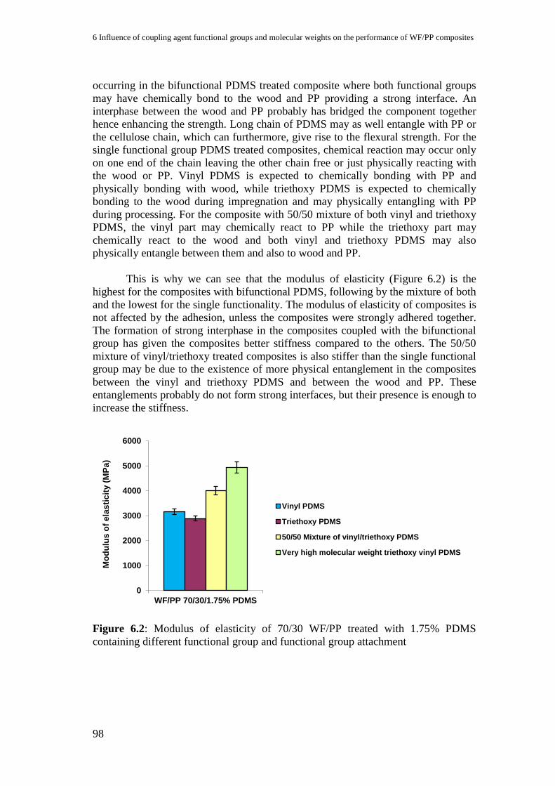
6 Influence of coupling agent functional groups and molecular weights on the performance of WF/PP composites
98
occurring in the bifunctional PDMS treated composite where both functional groups
may have chemically bond to the wood and PP providing a strong interface. An
interphase between the wood and PP probably has bridged the component together
hence enhancing the strength. Long chain of PDMS may as well entangle with PP or
the cellulose chain, which can furthermore, give rise to the flexural strength. For the
single functional group PDMS treated composites, chemical reaction may occur only
on one end of the chain leaving the other chain free or just physically reacting with
the wood or PP. Vinyl PDMS is expected to chemically bonding with PP and
physically bonding with wood, while triethoxy PDMS is expected to chemically
bonding to the wood during impregnation and may physically entangling with PP
during processing. For the composite with 50/50 mixture of both vinyl and triethoxy
PDMS, the vinyl part may chemically react to PP while the triethoxy part may
chemically react to the wood and both vinyl and triethoxy PDMS may also
physically entangle between them and also to wood and PP.
This is why we can see that the modulus of elasticity (Figure 6.2) is the
highest for the composites with bifunctional PDMS, following by the mixture of both
and the lowest for the single functionality. The modulus of elasticity of composites is
not affected by the adhesion, unless the composites were strongly adhered together.
The formation of strong interphase in the composites coupled with the bifunctional
group has given the composites better stiffness compared to the others. The 50/50
mixture of vinyl/triethoxy treated composites is also stiffer than the single functional
group may be due to the existence of more physical entanglement in the composites
between the vinyl and triethoxy PDMS and between the wood and PP. These
entanglements probably do not form strong interfaces, but their presence is enough to
increase the stiffness.
Figure 6.2: Modulus of elasticity of 70/30 WF/PP treated with 1.75% PDMS
containing different functional group and functional group attachment
0
1000
2000
3000
4000
5000
6000
WF/PP 70/30/1.75% PDMS
Mo
du
lus
of
ela
sti
cit
y (
MP
a)
Vinyl PDMS
Triethoxy PDMS
50/50 Mixture of vinyl/triethoxy PDMS
Very high molecular weight triethoxy vinyl PDMS

6.2 DMA analysis for different functional groups PDMS
99
6.2 DMA analysis for different functional groups PDMS
The DMA results of composite treated with a 50/50 mixture of the single functional
group PDMS show a slight higher transition in the glass transition temperature
comparing to the bifunctional PDMS treated composite (Figures 6.3 and 6.4). The
storage modulus is also higher for the mixture of single functional PDMS. DMA is
measuring the viscoelastic properties of materials at the molecular level. The
mobility of chain segments plays an important role in showing the results. A small
difference in the freedom of chain movement will affect the transition of the
materials. As discussed, the composite treated with the mixture of single functional
PDMS is expected to have more chain entanglement between coupling agents, wood
and PP chain. The higher Tg and storage modulus obtained with the composite
treated with 50/50 mixture of single PDMS could be due to the entanglement
phenomena. Thus, less segmental chain movements of the composite with the
mixture of single functional PDMS comparing to the bifunctional PDMS. However,
from the Arrhenius plot (Figure 6.5), the Ea of the glass transition has been
calculated, and it can be seen that the Ea for composite containing bifunctionality
PDMS is higher, which is 371 ± 3 kJ/mol compared to the mixture that is only 269 ±
1 kJ/mol. This shows that the interphase bonding in the bifunctional PDMS treated
composites is stronger than the interphase bonding in the mixture of the single
functional PDMS.
Figure 6.3: Storage modulus and loss modulus comparison of 70/30 WF/PP
composites containing 1.75% treatment of very high molecular weight bifunctional
triethoxy-vinyl PDMS and 50/50 mixture of triethoxy PDMS/vinyl PDMS.
0.0
0.1
0.2
0.3
0
1
2
3
4
5
-60 -10 40 90 140
Loss M
odulu
s (
Gpa)
Sto
rage M
odulu
s (
Gpa)
Temperature (°C)
E' Bifunctional PDMS E' Mixture of single functional PDMS
E'' Bifunctional PDMS E'' Mixture of single functional PDMS
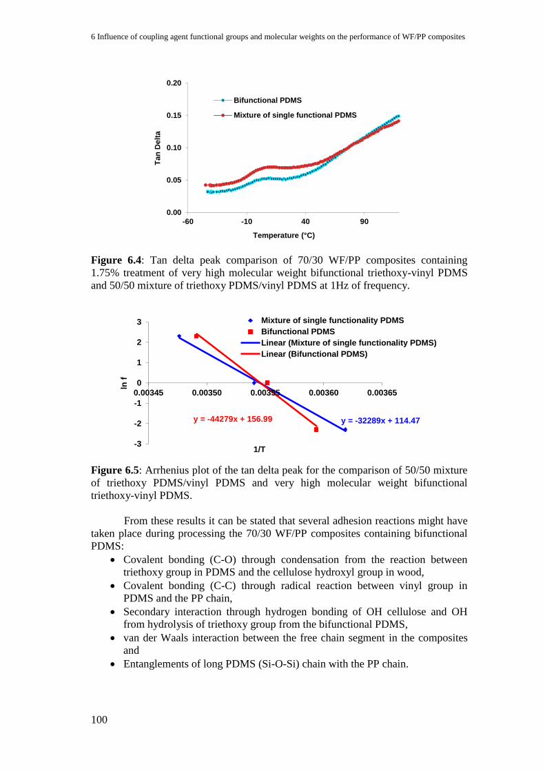
6 Influence of coupling agent functional groups and molecular weights on the performance of WF/PP composites
100
Figure 6.4: Tan delta peak comparison of 70/30 WF/PP composites containing
1.75% treatment of very high molecular weight bifunctional triethoxy-vinyl PDMS
and 50/50 mixture of triethoxy PDMS/vinyl PDMS at 1Hz of frequency.
Figure 6.5: Arrhenius plot of the tan delta peak for the comparison of 50/50 mixture
of triethoxy PDMS/vinyl PDMS and very high molecular weight bifunctional
triethoxy-vinyl PDMS.
From these results it can be stated that several adhesion reactions might have
taken place during processing the 70/30 WF/PP composites containing bifunctional
PDMS:
Covalent bonding (C-O) through condensation from the reaction between
triethoxy group in PDMS and the cellulose hydroxyl group in wood,
Covalent bonding (C-C) through radical reaction between vinyl group in
PDMS and the PP chain,
Secondary interaction through hydrogen bonding of OH cellulose and OH
from hydrolysis of triethoxy group from the bifunctional PDMS,
van der Waals interaction between the free chain segment in the composites
and
Entanglements of long PDMS (Si-O-Si) chain with the PP chain.
0.00
0.05
0.10
0.15
0.20
-60 -10 40 90
Tan
Delt
a
Temperature (°C)
Bifunctional PDMS
Mixture of single functional PDMS
y = -32289x + 114.47 y = -44279x + 156.99
-3
-2
-1
0
1
2
3
0.00345 0.00350 0.00355 0.00360 0.00365
ln f
1/T
Mixture of single functionality PDMS
Bifunctional PDMS
Linear (Mixture of single functionality PDMS)
Linear (Bifunctional PDMS)
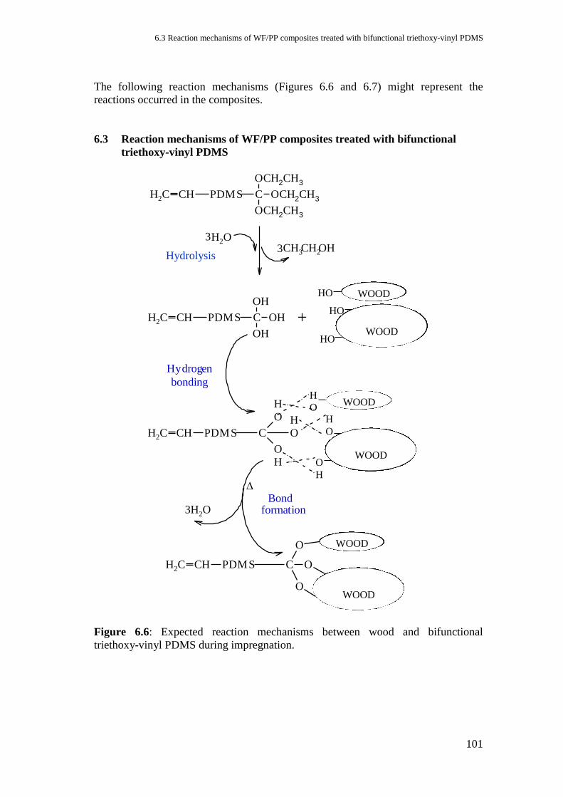
6.3 Reaction mechanisms of WF/PP composites treated with bifunctional triethoxy-vinyl PDMS
101
The following reaction mechanisms (Figures 6.6 and 6.7) might represent the
reactions occurred in the composites.
6.3 Reaction mechanisms of WF/PP composites treated with bifunctional
triethoxy-vinyl PDMS
CH2 CH PDMS C
OCH2CH3
OCH2CH3
OCH2CH3
Hidrolysis
OH23
CH2OHCH33
CH2 CH PDMS C
OH
OH
OH +
CH2 CH PDMS C
O
H
O
H
O
H
Hydrogen
bonding
CH2 CH PDMS C
O
O
O
3H2OBond
formation
WOOD HO
WOOD
H
O
HO
WOOD
HO
O
H
WOOD
H
O
WOOD
WOOD
Figure 6.6: Expected reaction mechanisms between wood and bifunctional
triethoxy-vinyl PDMS during impregnation.
Hydrolysis
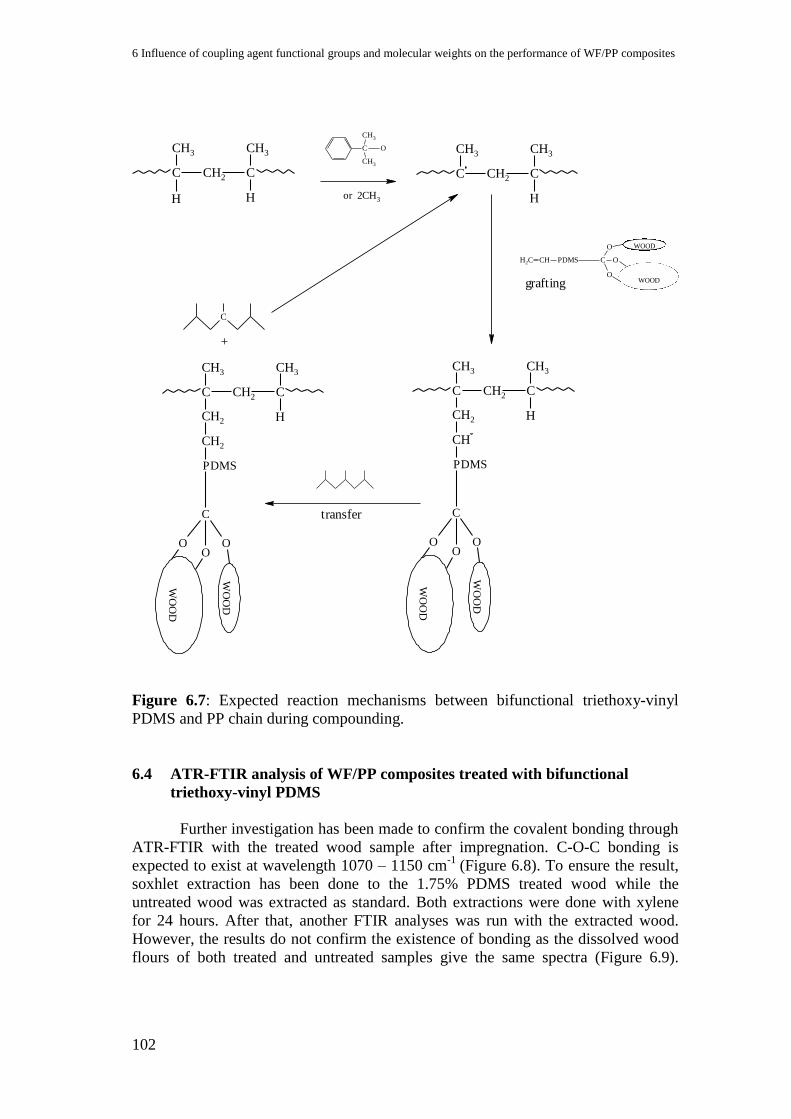
6 Influence of coupling agent functional groups and molecular weights on the performance of WF/PP composites
102
or CH32
C
CH3
CH3
O
C CH2 C
CH3 CH3
HH
C CH2 C
CH3 CH3
H
C CH2 C
CH3 CH3
HCH2
CH
PDMS
C
OOO
CH2 CH PDMS C
O
O
O
WOOD
WOOD
WO
OD
W
OO
D
transfer
C CH2 C
CH3 CH3
HCH2
CH2
PDMS
C
OOO
WO
OD
W
OO
D
C
grafting
+
Figure 6.7: Expected reaction mechanisms between bifunctional triethoxy-vinyl
PDMS and PP chain during compounding.
6.4 ATR-FTIR analysis of WF/PP composites treated with bifunctional
triethoxy-vinyl PDMS
Further investigation has been made to confirm the covalent bonding through
ATR-FTIR with the treated wood sample after impregnation. C-O-C bonding is
expected to exist at wavelength 1070 – 1150 cm-1
(Figure 6.8). To ensure the result,
soxhlet extraction has been done to the 1.75% PDMS treated wood while the
untreated wood was extracted as standard. Both extractions were done with xylene
for 24 hours. After that, another FTIR analyses was run with the extracted wood.
However, the results do not confirm the existence of bonding as the dissolved wood
flours of both treated and untreated samples give the same spectra (Figure 6.9).
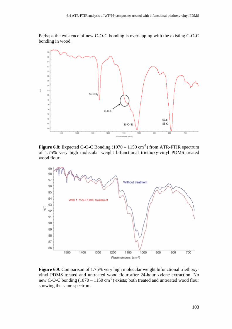
6.4 ATR-FTIR analysis of WF/PP composites treated with bifunctional triethoxy-vinyl PDMS
103
Perhaps the existence of new C-O-C bonding is overlapping with the existing C-O-C
bonding in wood.
Figure 6.8: Expected C-O-C Bonding (1070 – 1150 cm-1
) from ATR-FTIR spectrum
of 1.75% very high molecular weight bifunctional triethoxy-vinyl PDMS treated
wood flour.
Figure 6.9: Comparison of 1.75% very high molecular weight bifunctional triethoxy-
vinyl PDMS treated and untreated wood flour after 24-hour xylene extraction. No
new C-O-C bonding (1070 – 1150 cm-1
) exists; both treated and untreated wood flour
showing the same spectrum.

6 Influence of coupling agent functional groups and molecular weights on the performance of WF/PP composites
104
6.5 Microscopic images of WF/PP composites treated with bifunctional
triethoxy-vinyl PDMS
(a) (b)
Figure 6.10: Microscopic images of 70/30 WF/PP composites (a) treated with 1.75%
very high molecular weight bifunctional triethoxy-vinyl PDMS and (b) without
treatment at different magnification.
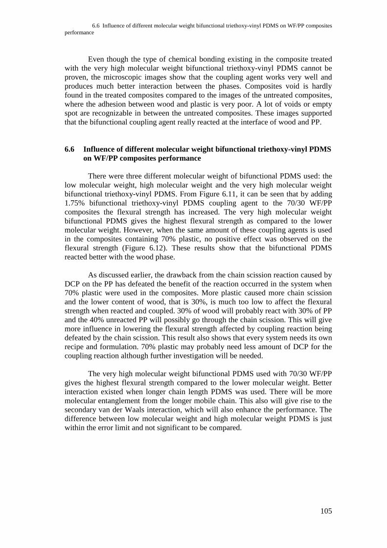
6.6 Influence of different molecular weight bifunctional triethoxy-vinyl PDMS on WF/PP composites
performance
105
Even though the type of chemical bonding existing in the composite treated
with the very high molecular weight bifunctional triethoxy-vinyl PDMS cannot be
proven, the microscopic images show that the coupling agent works very well and
produces much better interaction between the phases. Composites void is hardly
found in the treated composites compared to the images of the untreated composites,
where the adhesion between wood and plastic is very poor. A lot of voids or empty
spot are recognizable in between the untreated composites. These images supported
that the bifunctional coupling agent really reacted at the interface of wood and PP.
6.6 Influence of different molecular weight bifunctional triethoxy-vinyl PDMS
on WF/PP composites performance
There were three different molecular weight of bifunctional PDMS used: the
low molecular weight, high molecular weight and the very high molecular weight
bifunctional triethoxy-vinyl PDMS. From Figure 6.11, it can be seen that by adding
1.75% bifunctional triethoxy-vinyl PDMS coupling agent to the 70/30 WF/PP
composites the flexural strength has increased. The very high molecular weight
bifunctional PDMS gives the highest flexural strength as compared to the lower
molecular weight. However, when the same amount of these coupling agents is used
in the composites containing 70% plastic, no positive effect was observed on the
flexural strength (Figure 6.12). These results show that the bifunctional PDMS
reacted better with the wood phase.
As discussed earlier, the drawback from the chain scission reaction caused by
DCP on the PP has defeated the benefit of the reaction occurred in the system when
70% plastic were used in the composites. More plastic caused more chain scission
and the lower content of wood, that is 30%, is much too low to affect the flexural
strength when reacted and coupled. 30% of wood will probably react with 30% of PP
and the 40% unreacted PP will possibly go through the chain scission. This will give
more influence in lowering the flexural strength affected by coupling reaction being
defeated by the chain scission. This result also shows that every system needs its own
recipe and formulation. 70% plastic may probably need less amount of DCP for the
coupling reaction although further investigation will be needed.
The very high molecular weight bifunctional PDMS used with 70/30 WF/PP
gives the highest flexural strength compared to the lower molecular weight. Better
interaction existed when longer chain length PDMS was used. There will be more
molecular entanglement from the longer mobile chain. This also will give rise to the
secondary van der Waals interaction, which will also enhance the performance. The
difference between low molecular weight and high molecular weight PDMS is just
within the error limit and not significant to be compared.
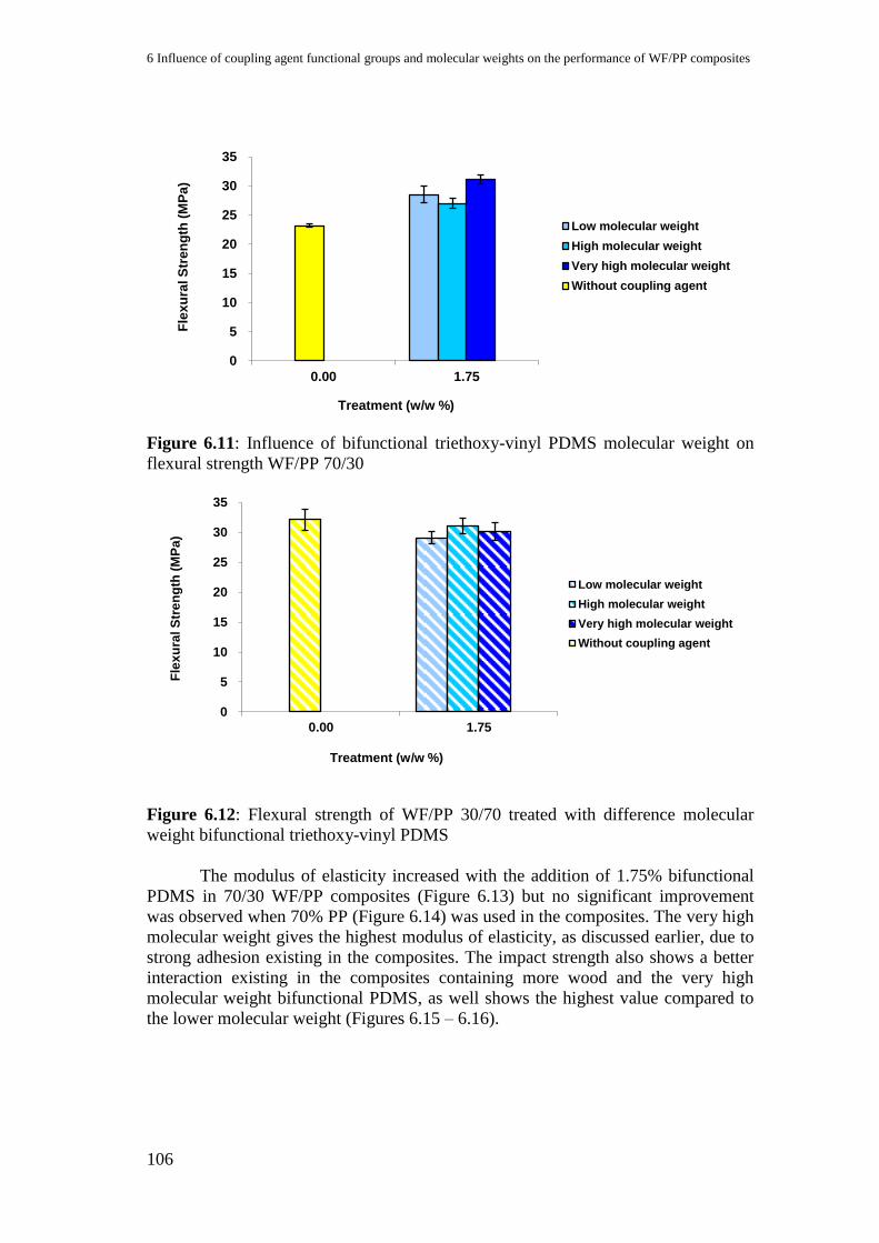
6 Influence of coupling agent functional groups and molecular weights on the performance of WF/PP composites
106
Figure 6.11: Influence of bifunctional triethoxy-vinyl PDMS molecular weight on
flexural strength WF/PP 70/30
Figure 6.12: Flexural strength of WF/PP 30/70 treated with difference molecular
weight bifunctional triethoxy-vinyl PDMS
The modulus of elasticity increased with the addition of 1.75% bifunctional
PDMS in 70/30 WF/PP composites (Figure 6.13) but no significant improvement
was observed when 70% PP (Figure 6.14) was used in the composites. The very high
molecular weight gives the highest modulus of elasticity, as discussed earlier, due to
strong adhesion existing in the composites. The impact strength also shows a better
interaction existing in the composites containing more wood and the very high
molecular weight bifunctional PDMS, as well shows the highest value compared to
the lower molecular weight (Figures 6.15 – 6.16).
0
5
10
15
20
25
30
35
0.00 1.75
Fle
xu
ral S
tre
ng
th (
MP
a)
Treatment (w/w %)
Low molecular weight
High molecular weight
Very high molecular weight
Without coupling agent
0
5
10
15
20
25
30
35
0.00 1.75
Fle
xu
ral S
tre
ng
th (
MP
a)
Treatment (w/w %)
Low molecular weight
High molecular weight
Very high molecular weight
Without coupling agent

6.6 Influence of different molecular weight bifunctional triethoxy-vinyl PDMS on WF/PP composites
performance
107
Figure 6.13: Influence of bifunctional triethoxy-vinyl PDMS molecular weight on
modulus of elasticity WF/PP 70/30
Figure 6.14: Modulus of elasticity of WF/PP 30/70 treated with difference molecular
weight bifunctional triethoxy-vinyl PDMS
0
1000
2000
3000
4000
5000
6000
0.00 1.75
Mo
du
lus
of
ela
sti
cit
y (
MP
a)
Treatment (w/w %)
Low molecular weight
High molecular weight
Very high molecular weight
Without coupling agent
0
1000
2000
3000
4000
5000
6000
0.00 1.75
Mo
du
lus
of
ela
sti
cit
y (
MP
a)
Treatment (w/w %)
Low molecular weight
High molecular weight
Very high molecular weight
Without coupling agent
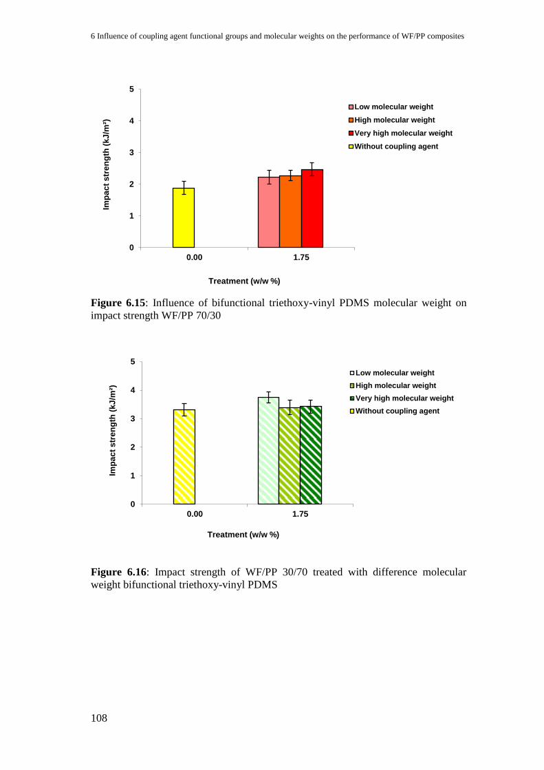
6 Influence of coupling agent functional groups and molecular weights on the performance of WF/PP composites
108
Figure 6.15: Influence of bifunctional triethoxy-vinyl PDMS molecular weight on
impact strength WF/PP 70/30
Figure 6.16: Impact strength of WF/PP 30/70 treated with difference molecular
weight bifunctional triethoxy-vinyl PDMS
0
1
2
3
4
5
0.00 1.75
Imp
ac
t s
tre
ng
th (
kJ
/m²)
Treatment (w/w %)
Low molecular weight
High molecular weight
Very high molecular weight
Without coupling agent
0
1
2
3
4
5
0.00 1.75
Imp
ac
t s
tren
gth
(k
J/m
²)
Treatment (w/w %)
Low molecular weight
High molecular weight
Very high molecular weight
Without coupling agent

109
7 Very high molecular weight bifunctional triethoxy-vinyl PDMS
coupling agent performance comparisons with industrially
established MAPP
The previous results have demonstrated the performance and characteristic of
the wood/polypropylene coupled by very high molecular weight bifunctional
triethoxy-vinyl PDMS. In Chapters 5 and 6 we have discussed and proved that this
new coupling agent can successfully enhance the properties of WPC produced
comparing to the neat WPC. However, it cannot be concluded how far the
improvements have achieved, if we do not standardize and compare them with
something widely been used in industry. In this chapter, we intend to compare the
mechanical properties and performance of our WPC with WPC containing industrial
MAPP that is Licocene PP MA 6252 from Clariant GmbH, Gersthofen, Germany.
MAPP has vastly been used in the wood plastic industry, and it is well known to
perform effectively (Ichazo et al., 2001; Acha et al., 2007).
The WPCs containing MAPP coupling agent that are used for the comparison
in this research were produced by the same processing method as producing WPC
containing PDMS coupling agent described in Chapter 3 sections 3.3. All the
samples for testing were prepared and tested the same way as with the very high
molecular weight bifunctional triethoxy-vinyl PDMS composites. The following
figures show the results.
7.1 Mechanical properties
Figure 7.1: Flexural strength performance comparison of coupling agent with
different composition
0
5
10
15
20
25
30
35
40
70/30 30/70
Fle
xu
ral s
tren
gth
(M
Pa
)
WF/PP composition (w/w %)
Untreated
1.75% MAPP
1.75% Bifunctional PDMS
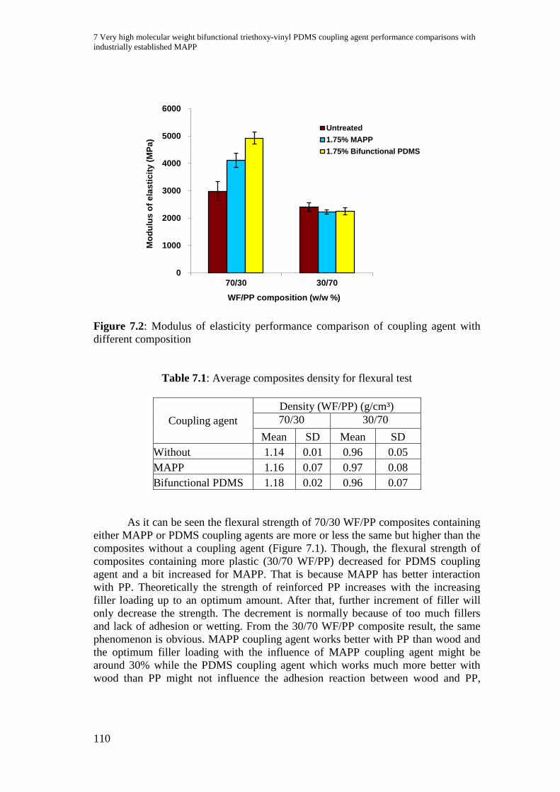
7 Very high molecular weight bifunctional triethoxy-vinyl PDMS coupling agent performance comparisons with
industrially established MAPP
110
Figure 7.2: Modulus of elasticity performance comparison of coupling agent with
different composition
Table 7.1: Average composites density for flexural test
Coupling agent
Density (WF/PP) (g/cm³)
70/30 30/70
Mean SD Mean SD
Without 1.14 0.01 0.96 0.05
MAPP 1.16 0.07 0.97 0.08
Bifunctional PDMS 1.18 0.02 0.96 0.07
As it can be seen the flexural strength of 70/30 WF/PP composites containing
either MAPP or PDMS coupling agents are more or less the same but higher than the
composites without a coupling agent (Figure 7.1). Though, the flexural strength of
composites containing more plastic (30/70 WF/PP) decreased for PDMS coupling
agent and a bit increased for MAPP. That is because MAPP has better interaction
with PP. Theoretically the strength of reinforced PP increases with the increasing
filler loading up to an optimum amount. After that, further increment of filler will
only decrease the strength. The decrement is normally because of too much fillers
and lack of adhesion or wetting. From the 30/70 WF/PP composite result, the same
phenomenon is obvious. MAPP coupling agent works better with PP than wood and
the optimum filler loading with the influence of MAPP coupling agent might be
around 30% while the PDMS coupling agent which works much more better with
wood than PP might not influence the adhesion reaction between wood and PP,
0
1000
2000
3000
4000
5000
6000
70/30 30/70
Mo
du
lus
of
ela
sti
cit
y (
MP
a)
WF/PP composition (w/w %)
Untreated
1.75% MAPP
1.75% Bifunctional PDMS

7.2 Microscopic images
111
giving lower optimum filler loading, which is why the value is lower than the
composites without a coupling agent.
The modulus of elasticity (Figure 7.2) of the composite treated with PDMS is
better than when 70% of wood was used, which is a normal phenomenon of a filled
plastic. No significant difference can be seen with 70% PP composites.
The results in Table 7.1 demonstrate that densities of the composites
containing the same composition of WF/PP with the different coupling agent are
comparable. Density of every tested sample also affects the result of mechanical
testing. The density of the composites does not vary so much between one another in
the same composition because they were pressed with a specific amount in a same
size of the frame with a similar hot press condition.
Figure 7.3: Impact strength performance comparison of coupling agent with
different composition
The impact strength (Figure 7.3) is not so significant to be discussed because
the results are within the error bars showing that impact strength is more affected by
the PP composition than by treatment.
7.2 Microscopic images
From Figure 7.4 we can see the microscopic images of both coupling agents
treated composites with 70/30 composition at the different magnification. Both
composites show comparable images with very good wood and PP interaction. Both
coupling agents have very homogenous surfaces and composite void is hardly found.
0
1
2
3
4
5
6
70/30 30/70
Imp
ac
t s
tren
gth
(k
J/m
²)
WF/PP composition (w/w %)
Untreated
1.75% MAPP
1.75% Bifunctional PDMS
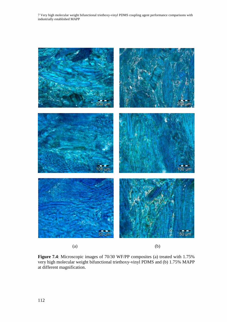
7 Very high molecular weight bifunctional triethoxy-vinyl PDMS coupling agent performance comparisons with
industrially established MAPP
112
(a) (b)
Figure 7.4: Microscopic images of 70/30 WF/PP composites (a) treated with 1.75%
very high molecular weight bifunctional triethoxy-vinyl PDMS and (b) 1.75% MAPP
at different magnification.
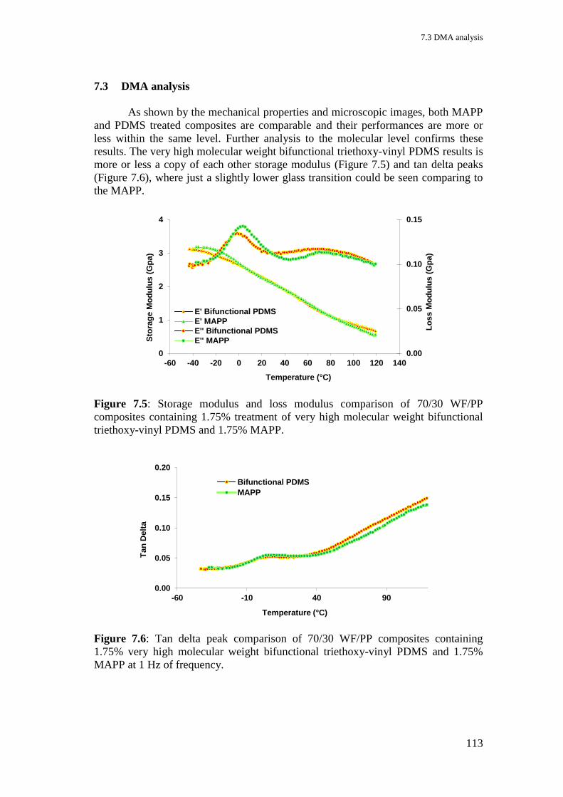
7.3 DMA analysis
113
7.3 DMA analysis
As shown by the mechanical properties and microscopic images, both MAPP
and PDMS treated composites are comparable and their performances are more or
less within the same level. Further analysis to the molecular level confirms these
results. The very high molecular weight bifunctional triethoxy-vinyl PDMS results is
more or less a copy of each other storage modulus (Figure 7.5) and tan delta peaks
(Figure 7.6), where just a slightly lower glass transition could be seen comparing to
the MAPP.
Figure 7.5: Storage modulus and loss modulus comparison of 70/30 WF/PP
composites containing 1.75% treatment of very high molecular weight bifunctional
triethoxy-vinyl PDMS and 1.75% MAPP.
Figure 7.6: Tan delta peak comparison of 70/30 WF/PP composites containing
1.75% very high molecular weight bifunctional triethoxy-vinyl PDMS and 1.75%
MAPP at 1 Hz of frequency.
0.00
0.05
0.10
0.15
0
1
2
3
4
-60 -40 -20 0 20 40 60 80 100 120 140
Lo
ss M
od
ulu
s (
Gp
a)
Sto
rag
e M
od
ulu
s (
Gp
a)
Temperature (°C)
E' Bifunctional PDMS
E' MAPP
E'' Bifunctional PDMS
E'' MAPP
0.00
0.05
0.10
0.15
0.20
-60 -10 40 90
Tan
Delt
a
Temperature (°C)
Bifunctional PDMS
MAPP
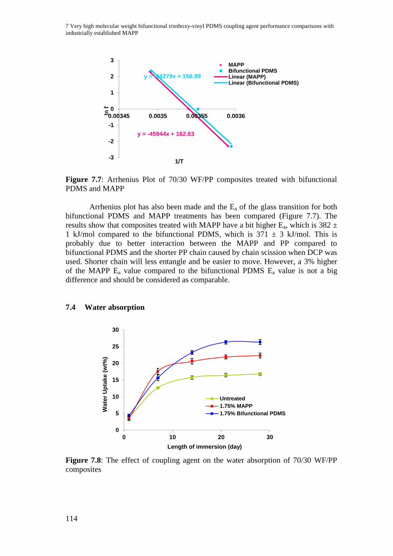
7 Very high molecular weight bifunctional triethoxy-vinyl PDMS coupling agent performance comparisons with
industrially established MAPP
114
Figure 7.7: Arrhenius Plot of 70/30 WF/PP composites treated with bifunctional
PDMS and MAPP
Arrhenius plot has also been made and the Ea of the glass transition for both
bifunctional PDMS and MAPP treatments has been compared (Figure 7.7). The
results show that composites treated with MAPP have a bit higher Ea, which is 382 ±
1 kJ/mol compared to the bifunctional PDMS, which is 371 ± 3 kJ/mol. This is
probably due to better interaction between the MAPP and PP compared to
bifunctional PDMS and the shorter PP chain caused by chain scission when DCP was
used. Shorter chain will less entangle and be easier to move. However, a 3% higher
of the MAPP Ea value compared to the bifunctional PDMS Ea value is not a big
difference and should be considered as comparable.
7.4 Water absorption
Figure 7.8: The effect of coupling agent on the water absorption of 70/30 WF/PP
composites
y = -45944x + 162.63
y = -44279x + 156.99
-3
-2
-1
0
1
2
3
0.00345 0.0035 0.00355 0.0036ln f
1/T
MAPPBifunctional PDMSLinear (MAPP)Linear (Bifunctional PDMS)
0
5
10
15
20
25
30
0 10 20 30
Wa
ter
Up
tak
e (
wt%
)
Length of immersion (day)
Untreated
1.75% MAPP
1.75% Bifunctional PDMS
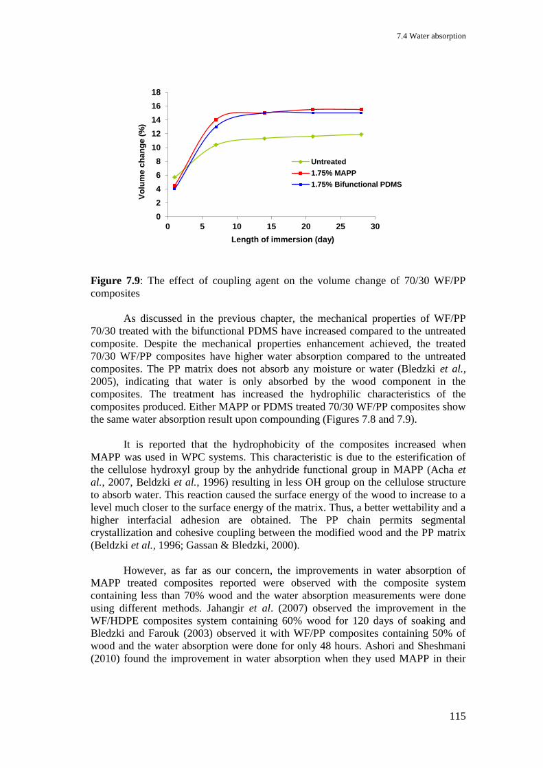
7.4 Water absorption
115
Figure 7.9: The effect of coupling agent on the volume change of 70/30 WF/PP
composites
As discussed in the previous chapter, the mechanical properties of WF/PP
70/30 treated with the bifunctional PDMS have increased compared to the untreated
composite. Despite the mechanical properties enhancement achieved, the treated
70/30 WF/PP composites have higher water absorption compared to the untreated
composites. The PP matrix does not absorb any moisture or water (Bledzki et al.,
2005), indicating that water is only absorbed by the wood component in the
composites. The treatment has increased the hydrophilic characteristics of the
composites produced. Either MAPP or PDMS treated 70/30 WF/PP composites show
the same water absorption result upon compounding (Figures 7.8 and 7.9).
It is reported that the hydrophobicity of the composites increased when
MAPP was used in WPC systems. This characteristic is due to the esterification of
the cellulose hydroxyl group by the anhydride functional group in MAPP (Acha et
al., 2007, Beldzki et al., 1996) resulting in less OH group on the cellulose structure
to absorb water. This reaction caused the surface energy of the wood to increase to a
level much closer to the surface energy of the matrix. Thus, a better wettability and a
higher interfacial adhesion are obtained. The PP chain permits segmental
crystallization and cohesive coupling between the modified wood and the PP matrix
(Beldzki et al., 1996; Gassan & Bledzki, 2000).
However, as far as our concern, the improvements in water absorption of
MAPP treated composites reported were observed with the composite system
containing less than 70% wood and the water absorption measurements were done
using different methods. Jahangir et al. (2007) observed the improvement in the
WF/HDPE composites system containing 60% wood for 120 days of soaking and
Bledzki and Farouk (2003) observed it with WF/PP composites containing 50% of
wood and the water absorption were done for only 48 hours. Ashori and Sheshmani
(2010) found the improvement in water absorption when they used MAPP in their
0
2
4
6
8
10
12
14
16
18
0 5 10 15 20 25 30
Vo
lum
e c
ha
ng
e (
%)
Length of immersion (day)
Untreated
1.75% MAPP
1.75% Bifunctional PDMS
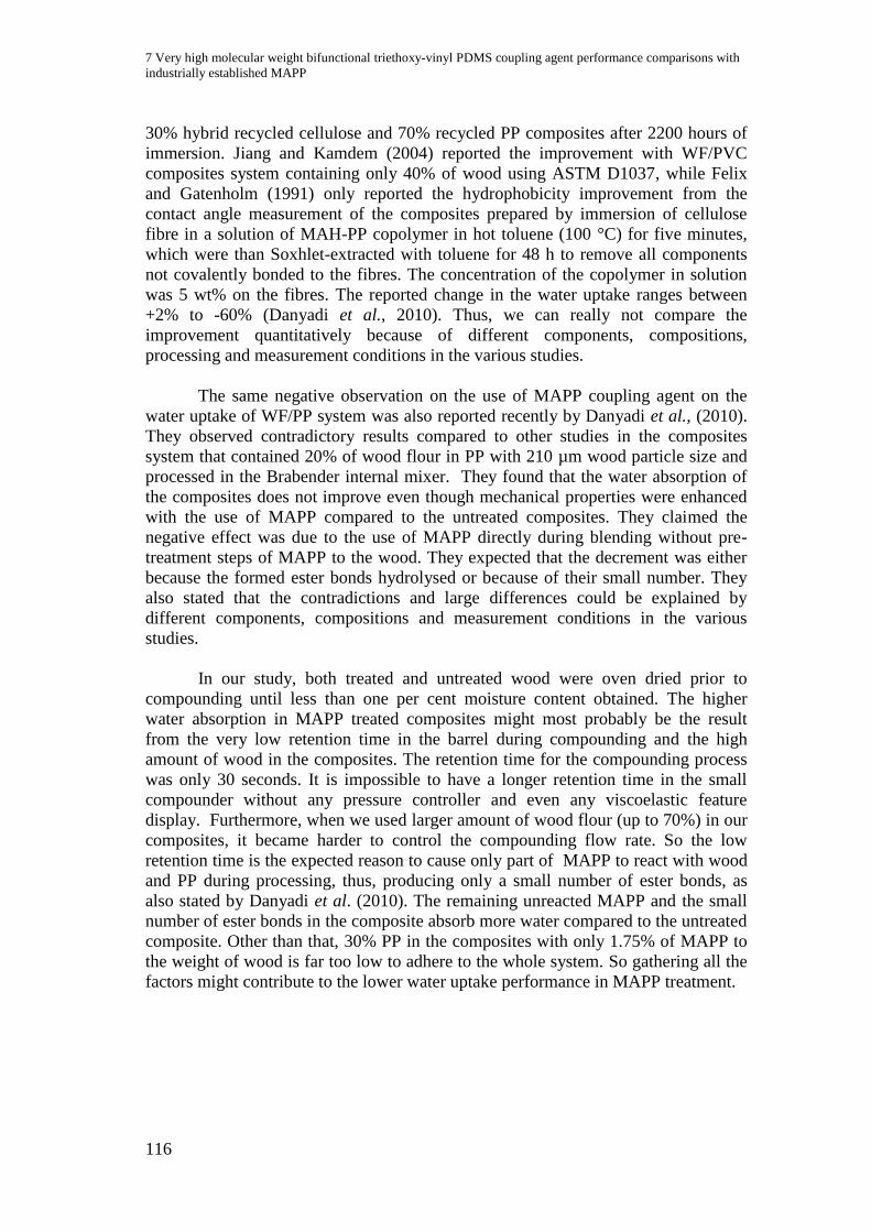
7 Very high molecular weight bifunctional triethoxy-vinyl PDMS coupling agent performance comparisons with
industrially established MAPP
116
30% hybrid recycled cellulose and 70% recycled PP composites after 2200 hours of
immersion. Jiang and Kamdem (2004) reported the improvement with WF/PVC
composites system containing only 40% of wood using ASTM D1037, while Felix
and Gatenholm (1991) only reported the hydrophobicity improvement from the
contact angle measurement of the composites prepared by immersion of cellulose
fibre in a solution of MAH-PP copolymer in hot toluene (100 °C) for five minutes,
which were than Soxhlet-extracted with toluene for 48 h to remove all components
not covalently bonded to the fibres. The concentration of the copolymer in solution
was 5 wt% on the fibres. The reported change in the water uptake ranges between
+2% to -60% (Danyadi et al., 2010). Thus, we can really not compare the
improvement quantitatively because of different components, compositions,
processing and measurement conditions in the various studies.
The same negative observation on the use of MAPP coupling agent on the
water uptake of WF/PP system was also reported recently by Danyadi et al., (2010).
They observed contradictory results compared to other studies in the composites
system that contained 20% of wood flour in PP with 210 µm wood particle size and
processed in the Brabender internal mixer. They found that the water absorption of
the composites does not improve even though mechanical properties were enhanced
with the use of MAPP compared to the untreated composites. They claimed the
negative effect was due to the use of MAPP directly during blending without pre-
treatment steps of MAPP to the wood. They expected that the decrement was either
because the formed ester bonds hydrolysed or because of their small number. They
also stated that the contradictions and large differences could be explained by
different components, compositions and measurement conditions in the various
studies.
In our study, both treated and untreated wood were oven dried prior to
compounding until less than one per cent moisture content obtained. The higher
water absorption in MAPP treated composites might most probably be the result
from the very low retention time in the barrel during compounding and the high
amount of wood in the composites. The retention time for the compounding process
was only 30 seconds. It is impossible to have a longer retention time in the small
compounder without any pressure controller and even any viscoelastic feature
display. Furthermore, when we used larger amount of wood flour (up to 70%) in our
composites, it became harder to control the compounding flow rate. So the low
retention time is the expected reason to cause only part of MAPP to react with wood
and PP during processing, thus, producing only a small number of ester bonds, as
also stated by Danyadi et al. (2010). The remaining unreacted MAPP and the small
number of ester bonds in the composite absorb more water compared to the untreated
composite. Other than that, 30% PP in the composites with only 1.75% of MAPP to
the weight of wood is far too low to adhere to the whole system. So gathering all the
factors might contribute to the lower water uptake performance in MAPP treatment.
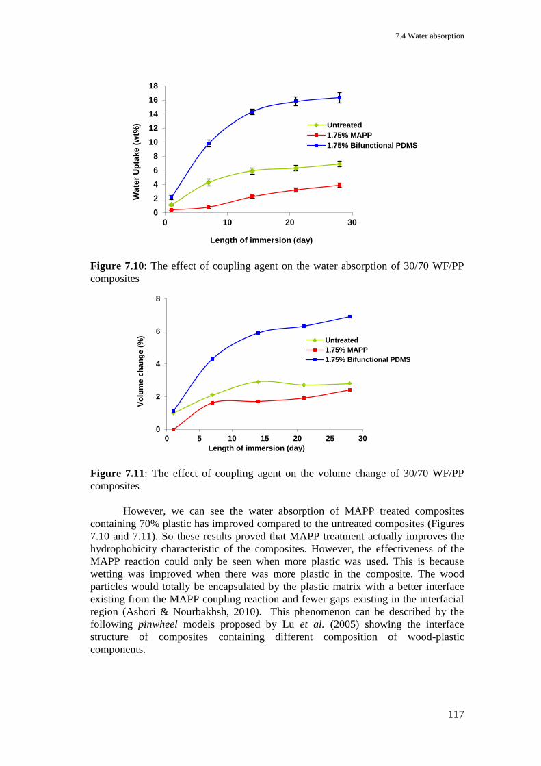
7.4 Water absorption
117
Figure 7.10: The effect of coupling agent on the water absorption of 30/70 WF/PP
composites
Figure 7.11: The effect of coupling agent on the volume change of 30/70 WF/PP
composites
However, we can see the water absorption of MAPP treated composites
containing 70% plastic has improved compared to the untreated composites (Figures
7.10 and 7.11). So these results proved that MAPP treatment actually improves the
hydrophobicity characteristic of the composites. However, the effectiveness of the
MAPP reaction could only be seen when more plastic was used. This is because
wetting was improved when there was more plastic in the composite. The wood
particles would totally be encapsulated by the plastic matrix with a better interface
existing from the MAPP coupling reaction and fewer gaps existing in the interfacial
region (Ashori & Nourbakhsh, 2010). This phenomenon can be described by the
following pinwheel models proposed by Lu et al. (2005) showing the interface
structure of composites containing different composition of wood-plastic
components.
0
2
4
6
8
10
12
14
16
18
0 10 20 30
Wa
ter
Up
tak
e (
wt%
)
Length of immersion (day)
Untreated
1.75% MAPP
1.75% Bifunctional PDMS
0
2
4
6
8
0 5 10 15 20 25 30
Vo
lum
e c
han
ge (
%)
Length of immersion (day)
Untreated
1.75% MAPP
1.75% Bifunctional PDMS
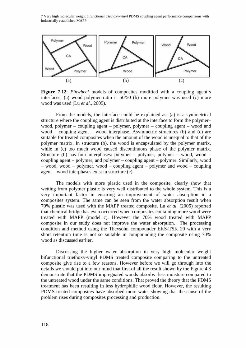
7 Very high molecular weight bifunctional triethoxy-vinyl PDMS coupling agent performance comparisons with
industrially established MAPP
118
(a) (b) (c)
Figure 7.12: Pinwheel models of composites modified with a coupling agent´s
interfaces; (a) wood-polymer ratio is 50/50 (b) more polymer was used (c) more
wood was used (Lu et al., 2005).
From the models, the interface could be explained as; (a) is a symmetrical
structure where the coupling agent is distributed at the interface to form the polymer–
wood, polymer – coupling agent – polymer, polymer – coupling agent – wood and
wood – coupling agent – wood interphase. Asymmetric structures (b) and (c) are
suitable for treated composites when the amount of the wood is unequal to that of the
polymer matrix. In structure (b), the wood is encapsulated by the polymer matrix,
while in (c) too much wood caused discontinuous phase of the polymer matrix.
Structure (b) has four interphases: polymer – polymer, polymer – wood, wood –
coupling agent – polymer, and polymer – coupling agent – polymer. Similarly, wood
– wood, wood – polymer, wood – coupling agent – polymer and wood – coupling
agent – wood interphases exist in structure (c).
The models with more plastic used in the composite, clearly show that
wetting from polymer plastic is very well distributed to the whole system. This is a
very important factor in ensuring an improvement of water absorption in a
composites system. The same can be seen from the water absorption result when
70% plastic was used with the MAPP treated composite. Lu et al. (2005) reported
that chemical bridge has even occurred when composites containing more wood were
treated with MAPP (model c). However the 70% wood treated with MAPP
composite in our study does not improve the water absorption. The processing
condition and method using the Theysohn compounder EKS-TSK 20 with a very
short retention time is not so suitable in compounding the composite using 70%
wood as discussed earlier.
Discussing the higher water absorption in very high molecular weight
bifunctional triethoxy-vinyl PDMS treated composite comparing to the untreated
composite give rise to a few reasons. However before we will go through into the
details we should put into our mind that first of all the result shown by the Figure 4.3
demonstrate that the PDMS impregnated woods absorbs less moisture compared to
the untreated wood under the same conditions. That proved the theory that the PDMS
treatment has been resulting in less hydrophilic wood flour. However, the resulting
PDMS treated composites have absorbed more water showing that the cause of the
problem rises during composites processing and production.
7.4 Water absorption
119
The first reason is the lack of wetting from plastic component in the 70/30
WF/PP composition as discussed in the MAPP treated composite earlier. Too much
wood causes that only part of it to be encapsulated by plastic matrix which is not
enough to improve hydrophobicity characteristic. The second reason is the
processing condition when using the small Theysohn co-rotating twin-screw
extrusion compounder EKS-TSK 20. As discussed earlier, the very low retention
time might cause the unfinished coupling reaction. On the other hand the very small
compounder with only 2 cm in diameter of the screw, when filled up with 70% of
unmelted wood particles at 280 to 350 rpm of speed, will generate a very high shear
rate in the barrel. This shear stress with the influence of the coupling agent and
peroxide initiator has probably broken the wood structure and produced some new
side products causing the composite having more hydrophilic characteristics than
before.
7.4.1 Sugar analysis and water absorption
The depolymerisation process of polysaccharides in wood to sugar monomer
could also be the cause of higher water absorption problem. There are several factors
influencing the depolymerisation process of wood to monomer, which are
temperature, pH, catalyst, and time. The PDMS used has a pH value of 4.3 and we
are convinced as well that the treatment lowered the processing temperature of the
treated composites about 20% (refer to Table 3.4). Wood is very sensitive to
temperature. For technical reasons described before, it was not possible to produce
the same composition of treated composites at the same processing temperature as
the untreated composites or the yield would be black burnt ash. From this condition,
we can say that the treated wood can easier degrade. Following this statement, we
can theoretically predict that some of our wood has undergone the degradation or
depolymerisation process producing sugar monomers, which will give rise to OH-
groups in the wood component of the composites. However, from the increments in
the mechanical properties, the results of microscopy images, and the DMA analysis
of the composites discussed earlier we can say that this degradation, nevertheless,
does not prevent the coupling agent reaction to become an interphase in the
composites. The reaction between the PP and vinyl groups still occurred and the
covalent bonding between PDMS and wood are at the same time existent, while the
monomer might react to each other through hydrogen bonding.
The following Figures 7.13 and 7.14 show the chromatogram of sugar
analysis of the untreated and PDMS treated composites. The analysis was done using
four points’ standard solutions with the calibration plot of every free sugar as
attached in the appendixes section. From the comparison of both chromatograms it
can be seen that the amount of free sugars in the treated composite is higher. From
the Tables 7.2 and 7.3, we can also see that the untreated composite contains the
overall of 108 mg/L free sugar while the treated composite contains 160 mg/L free
sugar, which is 48% more. The free sugars found in the untreated composite were
detected to be glucose, arabinose, galactose and xylose while in the treated

7 Very high molecular weight bifunctional triethoxy-vinyl PDMS coupling agent performance comparisons with
industrially established MAPP
120
composite beside the same sugars, one more sugar nominal cellobiose with only 0.5
mg/L was also detected.
Figure 7.13: Chromatogram of sugar analysis for untreated 70/30 WF/PP composite
Table 7.2: Sugar content for untreated 70/30 WF/PP composite
Peak Retention
Time Peak Name Height Area
Relative
Area Amount
No. (min) (nC) (nC*min) (%) (mg/L)
6 19.3 Arabinose 22.6 11.7 16.4 96.5
7 24.4 Galactose 1.7 1.0 1.4 5.0
8 28.3 Glucose 0.4 0.2 0.3 0.9
9 33.4 Xylose 1.5 1.0 1.3 5.1
Total: 26.1 13.8 19.5 107.5
0,0 10,0 20,0 30,0 40,0 50,0 65,0
-10,0
0,0
10,0
20,0
30,0
40,0
50,0
60,0BIRKE_PA_2 #5 C1 ED_1nC
min
6 -
Ara
bin
os
e -
19
,28
3
7 -
Ga
lac
tos
e -
24
,43
3
8 -
Glu
co
se
- 2
8,2
83
9 -
xy
los
e -
33
,40
0

7.4 Water absorption
121
Figure 7.14: Chromatogram of sugar analysis for 70/30 WF/PP composite treated
with 1.75% very high molecular weight bifunctional triethoxy-vinyl PDMS
Table 7.3: Sugar content for 70/30 WF/PP composite treated with 1.75% very high
molecular weight bifunctional triethoxy-vinyl PDMS
Peak Retention
Time Peak Name Height Area
Relative
Area Amount
No. (min) (nC) (nC*min) (%) (mg/L)
5 19.3 Arabinose 32.2 17.0 27.2 146.1
6 24.4 Galactose 2.0 1.2 1.8 5.8
7 28.3 Glucose 0.6 0.3 0.6 1.3
8 33.4 Xylose 1.8 1.2 1.8 6.2
16 50.7 Cellubiose 0.4 0.1 0.2 0.5
Total: 37.1 19.8 31.6 159.9
Basically two of the three lignocellulosic materials are made of repeating
units of the monosaccharide units of various types. The basic unit of cellulose is
‘cellobiose’. Hydroxyl group of cellulose makes fibrils by forming hydrogen bond
with hydroxyl groups neighbouring other cellulose molecular chains and partially
0,0 10,0 20,0 30,0 40,0 50,0 65,0
-10,0
0,0
12,5
25,0
37,5
50,0
70,0BIRKE_PA_2 #6 C2 ED_1nC
min
5 -
Ara
bin
os
e -
19
,28
3
6 -
Ga
lac
tos
e -
24
,43
3
7 -
Glu
co
se
- 2
8,3
00
8 -
xy
los
e -
33
,40
0
16
- C
ell
ub
ios
e -
50
,70
0
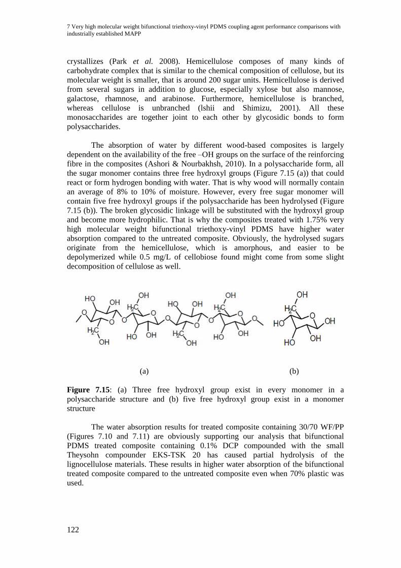
7 Very high molecular weight bifunctional triethoxy-vinyl PDMS coupling agent performance comparisons with
industrially established MAPP
122
crystallizes (Park et al. 2008). Hemicellulose composes of many kinds of
carbohydrate complex that is similar to the chemical composition of cellulose, but its
molecular weight is smaller, that is around 200 sugar units. Hemicellulose is derived
from several sugars in addition to glucose, especially xylose but also mannose,
galactose, rhamnose, and arabinose. Furthermore, hemicellulose is branched,
whereas cellulose is unbranched (lshii and Shimizu, 2001). All these
monosaccharides are together joint to each other by glycosidic bonds to form
polysaccharides.
The absorption of water by different wood-based composites is largely
dependent on the availability of the free –OH groups on the surface of the reinforcing
fibre in the composites (Ashori & Nourbakhsh, 2010). In a polysaccharide form, all
the sugar monomer contains three free hydroxyl groups (Figure 7.15 (a)) that could
react or form hydrogen bonding with water. That is why wood will normally contain
an average of 8% to 10% of moisture. However, every free sugar monomer will
contain five free hydroxyl groups if the polysaccharide has been hydrolysed (Figure
7.15 (b)). The broken glycosidic linkage will be substituted with the hydroxyl group
and become more hydrophilic. That is why the composites treated with 1.75% very
high molecular weight bifunctional triethoxy-vinyl PDMS have higher water
absorption compared to the untreated composite. Obviously, the hydrolysed sugars
originate from the hemicellulose, which is amorphous, and easier to be
depolymerized while 0.5 mg/L of cellobiose found might come from some slight
decomposition of cellulose as well.
(a) (b)
Figure 7.15: (a) Three free hydroxyl group exist in every monomer in a
polysaccharide structure and (b) five free hydroxyl group exist in a monomer
structure
The water absorption results for treated composite containing 30/70 WF/PP
(Figures 7.10 and 7.11) are obviously supporting our analysis that bifunctional
PDMS treated composite containing 0.1% DCP compounded with the small
Theysohn compounder EKS-TSK 20 has caused partial hydrolysis of the
lignocellulose materials. These results in higher water absorption of the bifunctional
treated composite compared to the untreated composite even when 70% plastic was
used.
123
8 The effect of treatment conditions and PP composition on WPC
performance
There are several ways or methods to apply the coupling agents during the
WPC production process. Depending on the form of coupling agent been used, the
available equipment and the chosen method, the outcomes or the effectiveness of the
treatments is varied. Every preparation will produce its own WPC characteristics.
Here we can see the different outcomes of the same coupling agent of distinct types
and applied using dissimilar methods of treatment. The coupling agent is very high
molecular weight bifunctional triethoxy-vinyl PDMS and the conditions are:
TEGOMER V-Si 4042 batch VB 3248, 100% purity in liquid form.
- Treatment was applied using impregnation procedure prior to
compounding as described in Chapter 3 section 3.2.1.
TEGO XP 6000 batch 294; 50% master batch VB3248 compounded in
Polypropylene.
- Treatment was applied using in situ processing, direct compounding as
described in Chapter 3 section 3.2.3.
TEGOPREN 6875-45 batch 3248; 50% emulsion of VB 3248
- Treatment was applied by spraying the coupling agent onto the wood
flour surfaces in a dry mixer prior to compounding as described in
Chapter 3 section 3.2.3.
All processing conditions applied during compounding following treatments
(impregnation and spraying method) were the same as the in situ processing
condition of the TEGO XP 6000 batch 294. The following figures show the results of
the WPC produced.
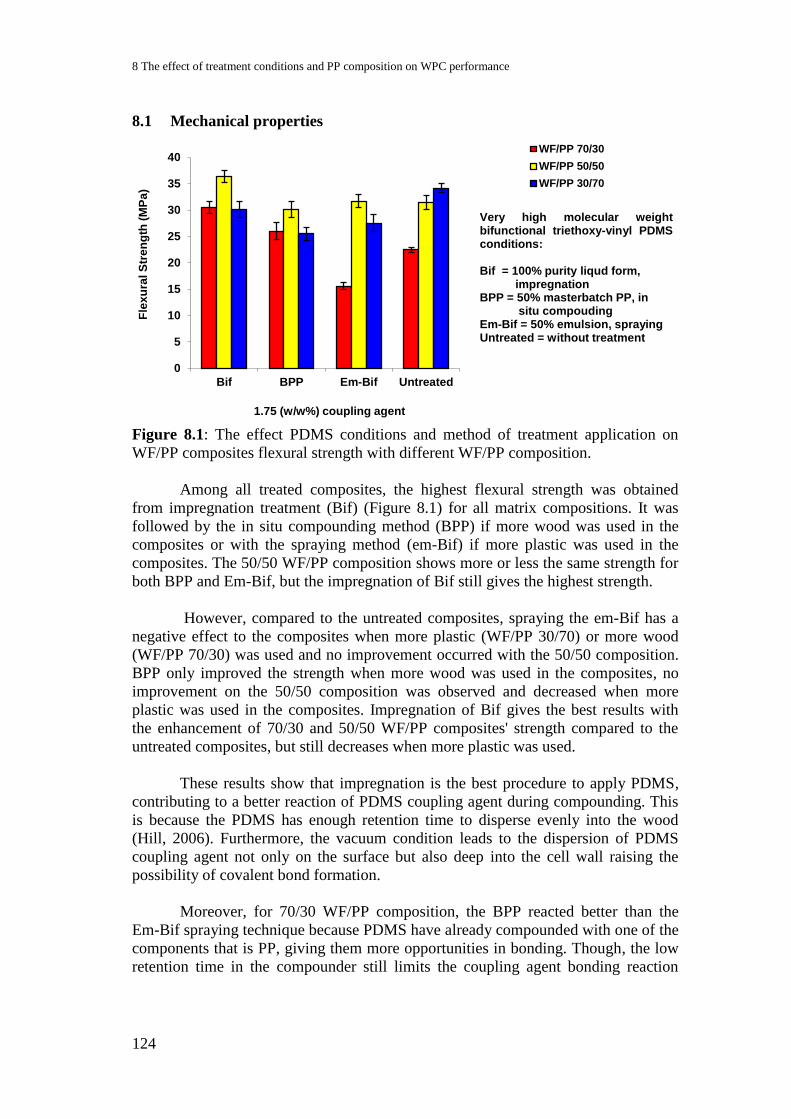
8 The effect of treatment conditions and PP composition on WPC performance
124
8.1 Mechanical properties
Figure 8.1: The effect PDMS conditions and method of treatment application on
WF/PP composites flexural strength with different WF/PP composition.
Among all treated composites, the highest flexural strength was obtained
from impregnation treatment (Bif) (Figure 8.1) for all matrix compositions. It was
followed by the in situ compounding method (BPP) if more wood was used in the
composites or with the spraying method (em-Bif) if more plastic was used in the
composites. The 50/50 WF/PP composition shows more or less the same strength for
both BPP and Em-Bif, but the impregnation of Bif still gives the highest strength.
However, compared to the untreated composites, spraying the em-Bif has a
negative effect to the composites when more plastic (WF/PP 30/70) or more wood
(WF/PP 70/30) was used and no improvement occurred with the 50/50 composition.
BPP only improved the strength when more wood was used in the composites, no
improvement on the 50/50 composition was observed and decreased when more
plastic was used in the composites. Impregnation of Bif gives the best results with
the enhancement of 70/30 and 50/50 WF/PP composites' strength compared to the
untreated composites, but still decreases when more plastic was used.
These results show that impregnation is the best procedure to apply PDMS,
contributing to a better reaction of PDMS coupling agent during compounding. This
is because the PDMS has enough retention time to disperse evenly into the wood
(Hill, 2006). Furthermore, the vacuum condition leads to the dispersion of PDMS
coupling agent not only on the surface but also deep into the cell wall raising the
possibility of covalent bond formation.
Moreover, for 70/30 WF/PP composition, the BPP reacted better than the
Em-Bif spraying technique because PDMS have already compounded with one of the
components that is PP, giving them more opportunities in bonding. Though, the low
retention time in the compounder still limits the coupling agent bonding reaction
0
5
10
15
20
25
30
35
40
Bif BPP Em-Bif Untreated
Fle
xu
ral S
tre
ng
th (
MP
a)
1.75 (w/w%) coupling agent
WF/PP 70/30
WF/PP 50/50
WF/PP 30/70
Very high molecular weight bifunctional triethoxy-vinyl PDMS conditions: Bif = 100% purity liqud form, impregnation BPP = 50% masterbatch PP, in situ compouding Em-Bif = 50% emulsion, spraying Untreated = without treatment
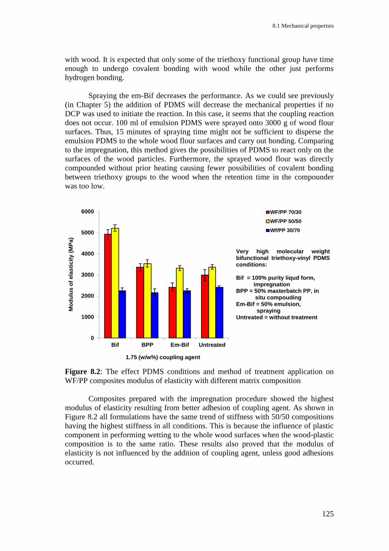
8.1 Mechanical properties
125
with wood. It is expected that only some of the triethoxy functional group have time
enough to undergo covalent bonding with wood while the other just performs
hydrogen bonding.
Spraying the em-Bif decreases the performance. As we could see previously
(in Chapter 5) the addition of PDMS will decrease the mechanical properties if no
DCP was used to initiate the reaction. In this case, it seems that the coupling reaction
does not occur. 100 ml of emulsion PDMS were sprayed onto 3000 g of wood flour
surfaces. Thus, 15 minutes of spraying time might not be sufficient to disperse the
emulsion PDMS to the whole wood flour surfaces and carry out bonding. Comparing
to the impregnation, this method gives the possibilities of PDMS to react only on the
surfaces of the wood particles. Furthermore, the sprayed wood flour was directly
compounded without prior heating causing fewer possibilities of covalent bonding
between triethoxy groups to the wood when the retention time in the compounder
was too low.
Figure 8.2: The effect PDMS conditions and method of treatment application on
WF/PP composites modulus of elasticity with different matrix composition
Composites prepared with the impregnation procedure showed the highest
modulus of elasticity resulting from better adhesion of coupling agent. As shown in
Figure 8.2 all formulations have the same trend of stiffness with 50/50 compositions
having the highest stiffness in all conditions. This is because the influence of plastic
component in performing wetting to the whole wood surfaces when the wood-plastic
composition is to the same ratio. These results also proved that the modulus of
elasticity is not influenced by the addition of coupling agent, unless good adhesions
occurred.
0
1000
2000
3000
4000
5000
6000
Bif BPP Em-Bif Untreated
Mo
du
lus
of
ela
sti
cit
y (
MP
a)
1.75 (w/w%) coupling agent
WF/PP 70/30
WF/PP 50/50
Wf/PP 30/70
Very high molecular weight bifunctional triethoxy-vinyl PDMS conditions: Bif = 100% purity liqud form, impregnation BPP = 50% masterbatch PP, in situ compouding Em-Bif = 50% emulsion, spraying Untreated = without treatment

8 The effect of treatment conditions and PP composition on WPC performance
126
Figure 8.3: The effect PDMS conditions and method of treatment application on
WF/PP composites impact strength with different matrix composition
Figure 8.3 shows that impact strengths of the composites are more affected by
the matrix composition. The higher PP content increases the ability of composites to
withstand the impact and prevent breakage and it can be seen that the highest impact
strength is obtained from the untreated composite with 70% PP. As discussed earlier,
DCP reaction in the treated composites have caused chain scission during processing.
This is probably the reason for lower impact strength obtained with the treated
composites even when 70% PP was used. In the case of Em-Bif treated composites,
there might be too little or almost no coupling reaction or adhesion occurred resulting
in the very similar trend to the untreated composites but with lower values. Em-Bif
maybe also acts as impurity in the systems and destroys the original interaction
between wood and plastic.
On the other hand, with Bif and BPP treatments, where good adhesion
occurred, another trend similar to each other regarding different WF/PP compositions
becomes obvious. However, BPP shows lower values representing lower adhesion in
the composites. Besides the matrix composition, good adhesion will prevent the
propagation of crack during impact breakage resulting in higher impact strength in
the composites with 70% wood when treated with Bif compared to BPP.
0
1
2
3
4
5
Bif BPP Em-Bif Untreated
Imp
ac
t s
tre
ng
th (
kJ
/m²)
1.75 (w/w%) coupling agent
WF/PP 70/30
WF/PP 50/50
WF/PP 30/70
Very high molecular weight bifunctional triethoxy-vinyl PDMS conditions: Bif = 100% purity liqud form, impregnation BPP = 50% masterbatch PP, in situ compouding Em-Bif = 50% emulsion, spraying Untreated = without treatment

8.2 Water absorption
127
8.2 Water absorption
Figure 8.4: Influence of 1.75% different conditions very high molecular weight
bifunctional triethoxy-vinyl PDMS on the water absorption of 70/30 WF/PP
composites
Figure 8.5: Influence of 1.75% different conditions very high molecular weight
bifunctional triethoxy-vinyl PDMS on the volume change of 70/30 WF/PP
composites
0
5
10
15
20
25
30
0 5 10 15 20 25 30
Wa
ter
Up
tak
e (
wt%
)
Length of immersion (day)
100% purity liquid form, impregnation
50% masterbatch PP, in situ compounding
50% emulsion, spraying
untreated
0
5
10
15
20
25
0 5 10 15 20 25 30
Vo
lum
e c
ha
ng
e (
%)
Length of immersion (day)
100% purity liqud form, impregnation
50% masterbatch PP, in situ compouding
50% emulsion, spraying
Untreated
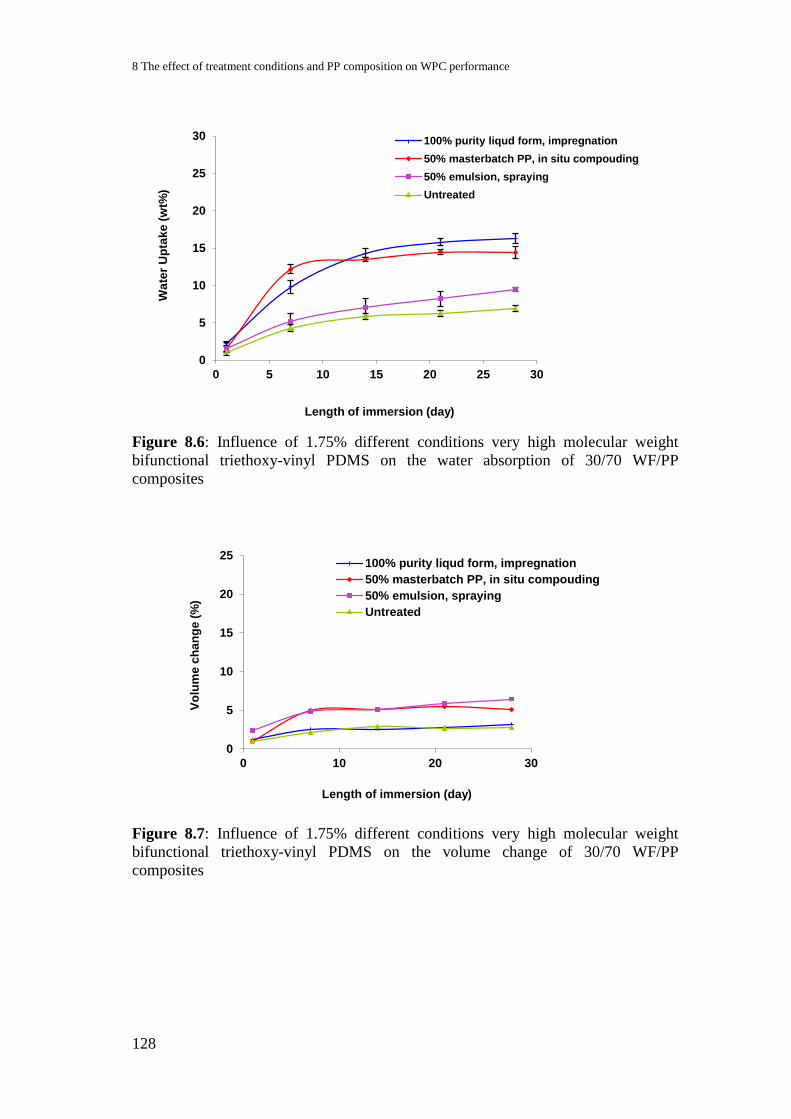
8 The effect of treatment conditions and PP composition on WPC performance
128
Figure 8.6: Influence of 1.75% different conditions very high molecular weight
bifunctional triethoxy-vinyl PDMS on the water absorption of 30/70 WF/PP
composites
Figure 8.7: Influence of 1.75% different conditions very high molecular weight
bifunctional triethoxy-vinyl PDMS on the volume change of 30/70 WF/PP
composites
0
5
10
15
20
25
30
0 5 10 15 20 25 30
Wa
ter
Up
tak
e (
wt%
)
Length of immersion (day)
100% purity liqud form, impregnation
50% masterbatch PP, in situ compouding
50% emulsion, spraying
Untreated
0
5
10
15
20
25
0 10 20 30
Vo
lum
e c
ha
ng
e (
%)
Length of immersion (day)
100% purity liqud form, impregnation
50% masterbatch PP, in situ compouding
50% emulsion, spraying
Untreated

8.2 Water absorption
129
Figure 8.8: Influence of 1.75% different conditions very high molecular weight
bifunctional triethoxy-vinyl PDMS on the water absorption of 50/50 WF/PP
composites
Figure 8.9: Influence of 1.75% different conditions very high molecular weight
bifunctional triethoxy-vinyl PDMS on the volume change of 50/50 WF/PP
composites
The water absorption values of all treatment conditions and composite
compositions are higher than those of the untreated composites. Composites using
impregnation method, containing more wood (WF/PP 70/30) showed the best results
regarding mechanical properties, followed by in situ compounding method and
spraying method (Figures 8.1 – 8.3). As discussed before, the improvement of
mechanical properties using impregnation method and in situ compounding method
might be due to better adhesion achieved. Higher water absorption of these two
methods compared to the untreated composite (Figure 8.4) is due to hydrolysis of
wood probably induced by the PDMS treatment, as shown by the results of the sugar
analyses of PDMS treated and untreated composites in Chapter 7, Figures 7.13 and
7.14. Assuming the polysaccharide chain undergo hydrolysis during coupling
reaction of PDMS, that might explain higher water absorption of impregnation
method compared to in situ compounding method.
0
5
10
15
20
25
30
0 10 20 30
Wa
ter
Up
tak
e (
wt%
)
Length of immersion (day)
100% purity liqud form, impregnation50% masterbatch PP, in situ compouding50% emulsion, sprayingUntreated
0
5
10
15
20
25
0 10 20 30
Vo
lum
e c
ha
ng
e (
%)
Length of immersion (day)
100% purity liqud form, impregnation50% masterbatch PP, in situ compouding50% emulsion, sprayingUntreated
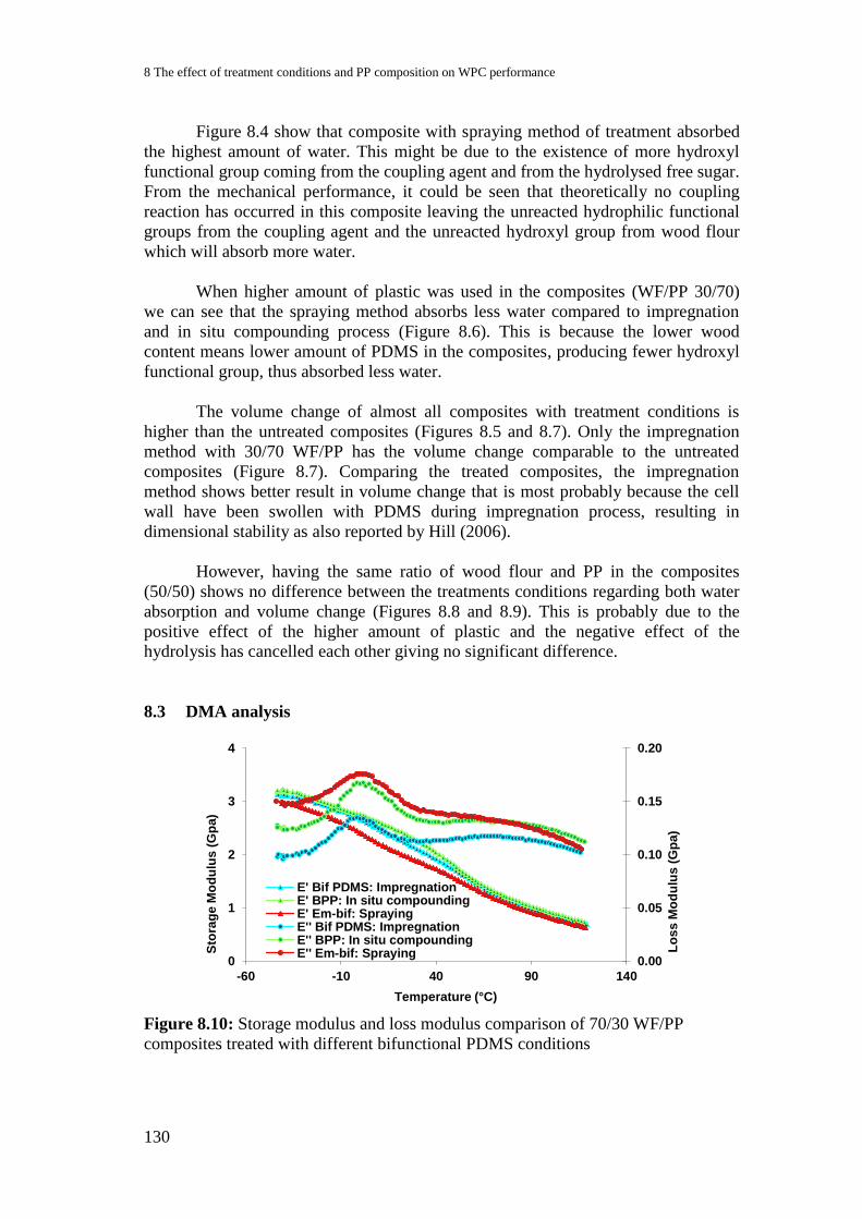
8 The effect of treatment conditions and PP composition on WPC performance
130
Figure 8.4 show that composite with spraying method of treatment absorbed
the highest amount of water. This might be due to the existence of more hydroxyl
functional group coming from the coupling agent and from the hydrolysed free sugar.
From the mechanical performance, it could be seen that theoretically no coupling
reaction has occurred in this composite leaving the unreacted hydrophilic functional
groups from the coupling agent and the unreacted hydroxyl group from wood flour
which will absorb more water.
When higher amount of plastic was used in the composites (WF/PP 30/70)
we can see that the spraying method absorbs less water compared to impregnation
and in situ compounding process (Figure 8.6). This is because the lower wood
content means lower amount of PDMS in the composites, producing fewer hydroxyl
functional group, thus absorbed less water.
The volume change of almost all composites with treatment conditions is
higher than the untreated composites (Figures 8.5 and 8.7). Only the impregnation
method with 30/70 WF/PP has the volume change comparable to the untreated
composites (Figure 8.7). Comparing the treated composites, the impregnation
method shows better result in volume change that is most probably because the cell
wall have been swollen with PDMS during impregnation process, resulting in
dimensional stability as also reported by Hill (2006).
However, having the same ratio of wood flour and PP in the composites
(50/50) shows no difference between the treatments conditions regarding both water
absorption and volume change (Figures 8.8 and 8.9). This is probably due to the
positive effect of the higher amount of plastic and the negative effect of the
hydrolysis has cancelled each other giving no significant difference.
8.3 DMA analysis
Figure 8.10: Storage modulus and loss modulus comparison of 70/30 WF/PP
composites treated with different bifunctional PDMS conditions
0.00
0.05
0.10
0.15
0.20
0
1
2
3
4
-60 -10 40 90 140
Lo
ss
Mo
du
lus (
Gp
a)
Sto
rag
e M
od
ulu
s (
Gp
a)
Temperature (°C)
E' Bif PDMS: ImpregnationE' BPP: In situ compoundingE' Em-bif: SprayingE'' Bif PDMS: ImpregnationE'' BPP: In situ compoundingE'' Em-bif: Spraying
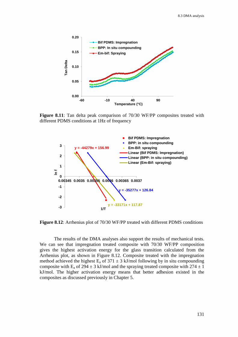
8.3 DMA analysis
131
Figure 8.11: Tan delta peak comparison of 70/30 WF/PP composites treated with
different PDMS conditions at 1Hz of frequency
Figure 8.12: Arrhenius plot of 70/30 WF/PP treated with different PDMS conditions
The results of the DMA analyses also support the results of mechanical tests.
We can see that impregnation treated composite with 70/30 WF/PP composition
gives the highest activation energy for the glass transition calculated from the
Arrhenius plot, as shown in Figure 8.12. Composite treated with the impregnation
method achieved the highest Ea of 371 ± 3 kJ/mol following by in situ compounding
composite with Ea of 294 ± 3 kJ/mol and the spraying treated composite with 274 ± 1
kJ/mol. The higher activation energy means that better adhesion existed in the
composites as discussed previously in Chapter 5.
0.00
0.05
0.10
0.15
0.20
-60 -10 40 90
Ta
n D
elt
a
Temperature (°C)
Bif PDMS: Impregnation
BPP: In situ compounding
Em-bif: Spraying
y = -44279x + 156.99
y = -35277x + 126.84
y = -33171x + 117.87 -3
-2
-1
0
1
2
3
0.00345 0.0035 0.00355 0.0036 0.00365 0.0037
ln f
1/T
Bif PDMS: Impregnation
BPP: in situ compounding
Em-Bif: spraying
Linear (Bif PDMS: Impregnation)
Linear (BPP: in situ compounding)
Linear (Em-Bif: spraying)

8 The effect of treatment conditions and PP composition on WPC performance
132
8.4 Microscopic analysis
Figure 8.13: Microscopic images of 70/30 WF/PP composites treated with different
treatment conditions of 1.75% very high molecular weight bifunctional triethoxy-
vinyl PDMS: (a) 100% purity liquid, impregnated, (b) 50% master batch PP, in situ
compounded, (c) 50% emulsion, sprayed and (d) untreated.
From the microscopic images in Figure 8.13 we can see the difference in the
composites' structures containing 70% wood. The impregnation treatment with a
better adhesion results in a very homogeneous structure, while some voids could be
found in the in situ compounded of 50% master batch PP. In the composite treated
with the spraying method, voids can be seen everywhere being worse than the
untreated composites.
The following images in Figure 8.14 of composites containing 70% PP also
show the same effects. Composites voids can be seen in all samples but the most
could be seen in the composites treated by in situ compounding and spraying
method. The untreated composite shows the best homogeneous structure.
(a) (b)
(c) (d)
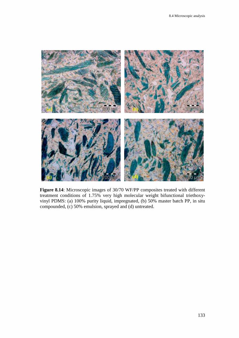
8.4 Microscopic analysis
133
Figure 8.14: Microscopic images of 30/70 WF/PP composites treated with different
treatment conditions of 1.75% very high molecular weight bifunctional triethoxy-
vinyl PDMS: (a) 100% purity liquid, impregnated, (b) 50% master batch PP, in situ
compounded, (c) 50% emulsion, sprayed and (d) untreated.
(a) (b)
(c) (d)
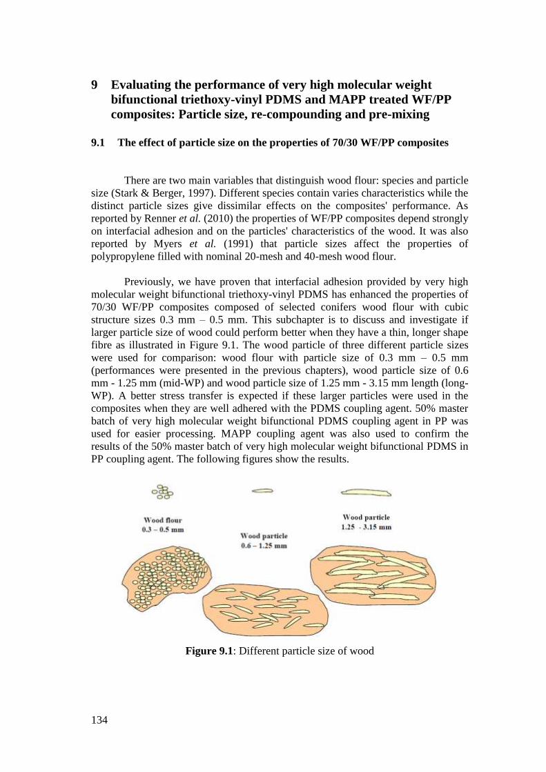
134
9 Evaluating the performance of very high molecular weight
bifunctional triethoxy-vinyl PDMS and MAPP treated WF/PP
composites: Particle size, re-compounding and pre-mixing
9.1 The effect of particle size on the properties of 70/30 WF/PP composites
There are two main variables that distinguish wood flour: species and particle
size (Stark & Berger, 1997). Different species contain varies characteristics while the
distinct particle sizes give dissimilar effects on the composites' performance. As
reported by Renner et al. (2010) the properties of WF/PP composites depend strongly
on interfacial adhesion and on the particles' characteristics of the wood. It was also
reported by Myers et al. (1991) that particle sizes affect the properties of
polypropylene filled with nominal 20-mesh and 40-mesh wood flour.
Previously, we have proven that interfacial adhesion provided by very high
molecular weight bifunctional triethoxy-vinyl PDMS has enhanced the properties of
70/30 WF/PP composites composed of selected conifers wood flour with cubic
structure sizes 0.3 mm – 0.5 mm. This subchapter is to discuss and investigate if
larger particle size of wood could perform better when they have a thin, longer shape
fibre as illustrated in Figure 9.1. The wood particle of three different particle sizes
were used for comparison: wood flour with particle size of 0.3 mm – 0.5 mm
(performances were presented in the previous chapters), wood particle size of 0.6
mm - 1.25 mm (mid-WP) and wood particle size of 1.25 mm - 3.15 mm length (long-
WP). A better stress transfer is expected if these larger particles were used in the
composites when they are well adhered with the PDMS coupling agent. 50% master
batch of very high molecular weight bifunctional PDMS coupling agent in PP was
used for easier processing. MAPP coupling agent was also used to confirm the
results of the 50% master batch of very high molecular weight bifunctional PDMS in
PP coupling agent. The following figures show the results.
Figure 9.1: Different particle size of wood
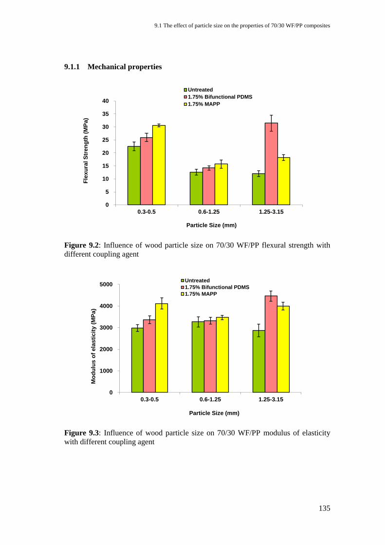
9.1 The effect of particle size on the properties of 70/30 WF/PP composites
135
9.1.1 Mechanical properties
Figure 9.2: Influence of wood particle size on 70/30 WF/PP flexural strength with
different coupling agent
Figure 9.3: Influence of wood particle size on 70/30 WF/PP modulus of elasticity
with different coupling agent
0
5
10
15
20
25
30
35
40
0.3-0.5 0.6-1.25 1.25-3.15
Fle
xu
ral S
tre
ng
th (
MP
a)
Particle Size (mm)
Untreated
1.75% Bifunctional PDMS
1.75% MAPP
0
1000
2000
3000
4000
5000
0.3-0.5 0.6-1.25 1.25-3.15
Mo
du
lus
of
ela
sti
cit
y (
MP
a)
Particle Size (mm)
Untreated
1.75% Bifunctional PDMS
1.75% MAPP
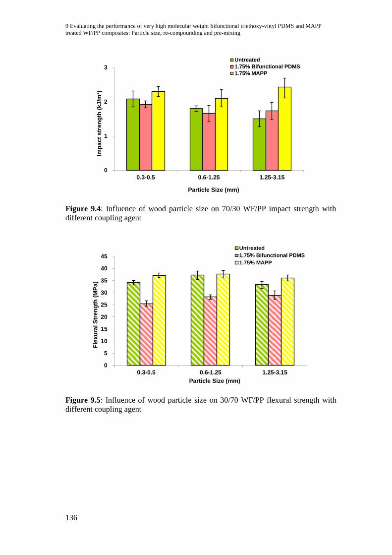
9 Evaluating the performance of very high molecular weight bifunctional triethoxy-vinyl PDMS and MAPP
treated WF/PP composites: Particle size, re-compounding and pre-mixing
136
Figure 9.4: Influence of wood particle size on 70/30 WF/PP impact strength with
different coupling agent
Figure 9.5: Influence of wood particle size on 30/70 WF/PP flexural strength with
different coupling agent
0
1
2
3
0.3-0.5 0.6-1.25 1.25-3.15
Imp
ac
t s
tre
ng
th (
kJ
/m²)
Particle Size (mm)
Untreated
1.75% Bifunctional PDMS
1.75% MAPP
0
5
10
15
20
25
30
35
40
45
0.3-0.5 0.6-1.25 1.25-3.15
Fle
xu
ral S
tren
gth
(M
Pa
)
Particle Size (mm)
Untreated
1.75% Bifunctional PDMS
1.75% MAPP
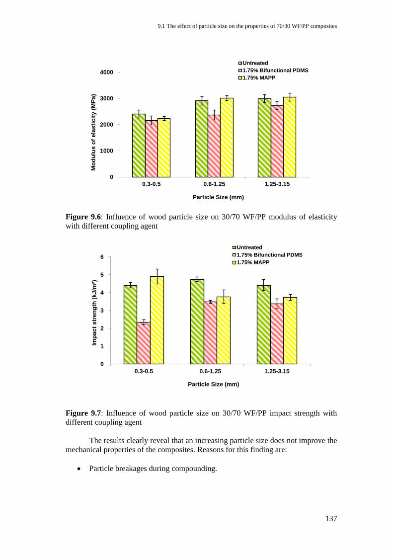
9.1 The effect of particle size on the properties of 70/30 WF/PP composites
137
Figure 9.6: Influence of wood particle size on 30/70 WF/PP modulus of elasticity
with different coupling agent
Figure 9.7: Influence of wood particle size on 30/70 WF/PP impact strength with
different coupling agent
The results clearly reveal that an increasing particle size does not improve the
mechanical properties of the composites. Reasons for this finding are:
Particle breakages during compounding.
0
1000
2000
3000
4000
0.3-0.5 0.6-1.25 1.25-3.15
Mo
du
lus
of
ela
sti
cit
y (
MP
a)
Particle Size (mm)
Untreated
1.75% Bifunctional PDMS
1.75% MAPP
0
1
2
3
4
5
6
0.3-0.5 0.6-1.25 1.25-3.15
Imp
ac
t s
tren
gth
(k
J/m
²)
Particle Size (mm)
Untreated
1.75% Bifunctional PDMS
1.75% MAPP
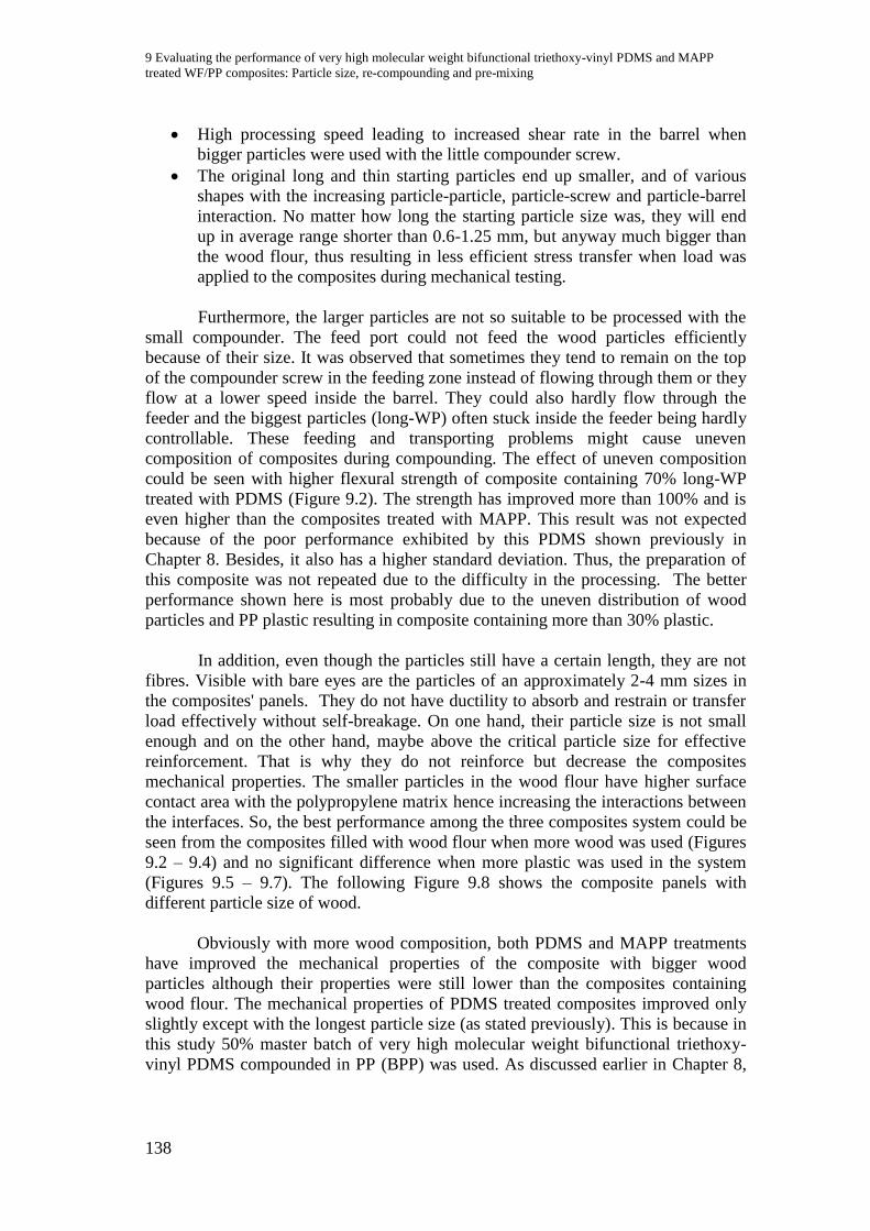
9 Evaluating the performance of very high molecular weight bifunctional triethoxy-vinyl PDMS and MAPP
treated WF/PP composites: Particle size, re-compounding and pre-mixing
138
High processing speed leading to increased shear rate in the barrel when
bigger particles were used with the little compounder screw.
The original long and thin starting particles end up smaller, and of various
shapes with the increasing particle-particle, particle-screw and particle-barrel
interaction. No matter how long the starting particle size was, they will end
up in average range shorter than 0.6-1.25 mm, but anyway much bigger than
the wood flour, thus resulting in less efficient stress transfer when load was
applied to the composites during mechanical testing.
Furthermore, the larger particles are not so suitable to be processed with the
small compounder. The feed port could not feed the wood particles efficiently
because of their size. It was observed that sometimes they tend to remain on the top
of the compounder screw in the feeding zone instead of flowing through them or they
flow at a lower speed inside the barrel. They could also hardly flow through the
feeder and the biggest particles (long-WP) often stuck inside the feeder being hardly
controllable. These feeding and transporting problems might cause uneven
composition of composites during compounding. The effect of uneven composition
could be seen with higher flexural strength of composite containing 70% long-WP
treated with PDMS (Figure 9.2). The strength has improved more than 100% and is
even higher than the composites treated with MAPP. This result was not expected
because of the poor performance exhibited by this PDMS shown previously in
Chapter 8. Besides, it also has a higher standard deviation. Thus, the preparation of
this composite was not repeated due to the difficulty in the processing. The better
performance shown here is most probably due to the uneven distribution of wood
particles and PP plastic resulting in composite containing more than 30% plastic.
In addition, even though the particles still have a certain length, they are not
fibres. Visible with bare eyes are the particles of an approximately 2-4 mm sizes in
the composites' panels. They do not have ductility to absorb and restrain or transfer
load effectively without self-breakage. On one hand, their particle size is not small
enough and on the other hand, maybe above the critical particle size for effective
reinforcement. That is why they do not reinforce but decrease the composites
mechanical properties. The smaller particles in the wood flour have higher surface
contact area with the polypropylene matrix hence increasing the interactions between
the interfaces. So, the best performance among the three composites system could be
seen from the composites filled with wood flour when more wood was used (Figures
9.2 – 9.4) and no significant difference when more plastic was used in the system
(Figures 9.5 – 9.7). The following Figure 9.8 shows the composite panels with
different particle size of wood.
Obviously with more wood composition, both PDMS and MAPP treatments
have improved the mechanical properties of the composite with bigger wood
particles although their properties were still lower than the composites containing
wood flour. The mechanical properties of PDMS treated composites improved only
slightly except with the longest particle size (as stated previously). This is because in
this study 50% master batch of very high molecular weight bifunctional triethoxy-
vinyl PDMS compounded in PP (BPP) was used. As discussed earlier in Chapter 8,

9.1 The effect of particle size on the properties of 70/30 WF/PP composites
139
the BPP was not so effective in coupling the composite although these results still
show that the treatment has improved the adhesion. The results also show that the
higher surface area for interaction between wood and coupling agent or matrix is
needed in enhancing the mechanical properties of the composites filled with wood
particles.
(a) (b)
Figure 9.8: WF/PP 70/30 panels with 1.75% very high molecular weight
bifunctional triethoxy-vinyl PDMS (a) with particle size of 0.3 – 0.5 mm and (b)
with particle size of 0.6 – 1.25 mm
9.1.2 Water absorption
Figure 9.9: Water absorption of 70/30 WF/PP with or without 1.75% MAPP or very
high molecular weight bifunctional triethoxy-vinyl PDMS (Bif PDMS) coupling
agent in the composites containing different particle size of wood.
From Figure 9.9, we can also see that, when 70% of wood was used, the
water absorption of the untreated composites increases with the increasing of particle
size. The MAPP treatment caused no significant effect on the water absorption
0
5
10
15
20
25
30
35
40
45
0 5 10 15 20 25 30
Wa
ter
Up
tak
e (
wt%
)
Length of immersion (day)
Bif PDMS/0.3-0.5mm
Untreated/0.3-0.5mm
MAPP/0.3-0.5mm
Bif PDMS/0.6-1.25mm
Untreated/0.6-1.25mm
MAPP/0.6-1.25mm
Bif PDMS/1.25-3.15mm
Untreated/1.25-3.15mm
MAPP/1.25-3.15mm
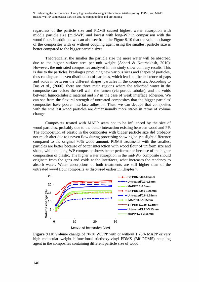
9 Evaluating the performance of very high molecular weight bifunctional triethoxy-vinyl PDMS and MAPP
treated WF/PP composites: Particle size, re-compounding and pre-mixing
140
regardless of the particle size and PDMS caused highest water absorption with
middle particle size (mid-WP) and lowest with long-WP in comparison with the
wood flour. In addition, we can also see from the Figure 9.10 that the volume change
of the composites with or without coupling agent using the smallest particle size is
better compared to the bigger particle sizes.
Theoretically, the smaller the particle size the more water will be absorbed
due to the higher surface area per unit weight (Ashori & Nourbakhsh, 2010).
However, the untreated composites analysed in this study show contrary results. This
is due to the particles' breakages producing new various sizes and shapes of particles,
thus causing an uneven distribution of particles, which leads to the existence of gaps
and voids in between the different shapes' particles in the composites. According to
Das et al., (2000), there are three main regions where the adsorbed water in the
composite can reside: the cell wall, the lumen (via porous tubular), and the voids
between lignocellulosic material and PP in the case of weak interface adhesion. We
can see from the flexural strength of untreated composites that the bigger particles'
composites have poorer interface adhesion. Thus, we can deduce that composites
with the smallest wood particles are dimensionally more stable in terms of volume
change.
Composites treated with MAPP seem not to be influenced by the size of
wood particles, probably due to the better interaction existing between wood and PP.
The composition of plastic in the composites with bigger particle size did probably
not much alter due to uneven flow during processing showing only a slight difference
compared to the original 70% wood amount. PDMS treatments with the smallest
particles are better because of better interaction with wood flour of uniform size and
shape, while the long-WP composite shows better performance because of the higher
composition of plastic. The higher water absorption in the mid-WP composite should
originate from the gaps and voids at the interfaces, what increases the tendency to
absorb water. Water absorptions of both treatments are still higher than of the
untreated wood flour composite as discussed earlier in Chapter 7.
Figure 9.10: Volume change of 70/30 WF/PP with or without 1.75% MAPP or very
high molecular weight bifunctional triethoxy-vinyl PDMS (Bif PDMS) coupling
agent in the composites containing different particle size of wood.
0
5
10
15
20
25
0 10 20 30
Vo
lum
e c
ha
ng
e (
%)
Length of immersion (day)
Bif PDMS/0.3-0.5mm
Untreated/0.3-0.5mm
MAPP/0.3-0.5mm
Bif PDMS/0.6-1.25mm
Untreated/0.6-1.25mm
MAPP/0.6-1.25mm
Bif PDMS/1.25-3.15mm
Untreated/1.25-3.15mm
MAPP/1.25-3.15mm
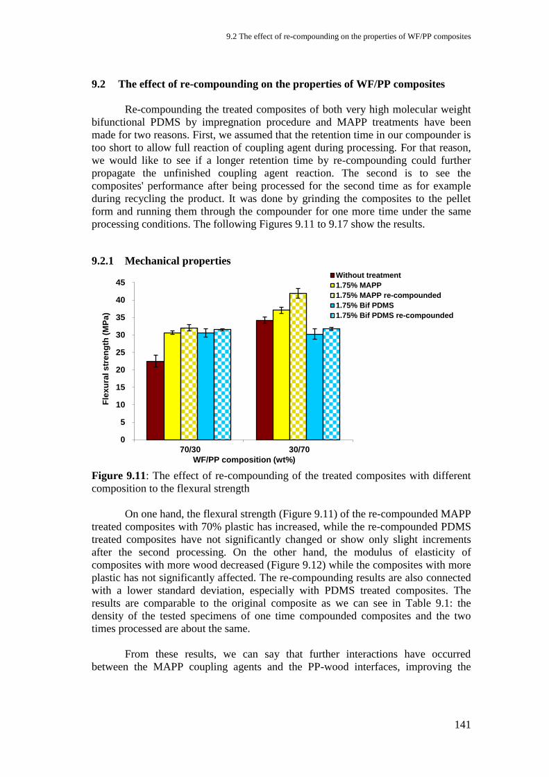
9.2 The effect of re-compounding on the properties of WF/PP composites
141
9.2 The effect of re-compounding on the properties of WF/PP composites
Re-compounding the treated composites of both very high molecular weight
bifunctional PDMS by impregnation procedure and MAPP treatments have been
made for two reasons. First, we assumed that the retention time in our compounder is
too short to allow full reaction of coupling agent during processing. For that reason,
we would like to see if a longer retention time by re-compounding could further
propagate the unfinished coupling agent reaction. The second is to see the
composites' performance after being processed for the second time as for example
during recycling the product. It was done by grinding the composites to the pellet
form and running them through the compounder for one more time under the same
processing conditions. The following Figures 9.11 to 9.17 show the results.
9.2.1 Mechanical properties
Figure 9.11: The effect of re-compounding of the treated composites with different
composition to the flexural strength
On one hand, the flexural strength (Figure 9.11) of the re-compounded MAPP
treated composites with 70% plastic has increased, while the re-compounded PDMS
treated composites have not significantly changed or show only slight increments
after the second processing. On the other hand, the modulus of elasticity of
composites with more wood decreased (Figure 9.12) while the composites with more
plastic has not significantly affected. The re-compounding results are also connected
with a lower standard deviation, especially with PDMS treated composites. The
results are comparable to the original composite as we can see in Table 9.1: the
density of the tested specimens of one time compounded composites and the two
times processed are about the same.
From these results, we can say that further interactions have occurred
between the MAPP coupling agents and the PP-wood interfaces, improving the
0
5
10
15
20
25
30
35
40
45
70/30 30/70
Fle
xu
ral s
tren
gth
(M
Pa
)
WF/PP composition (wt%)
Without treatment
1.75% MAPP
1.75% MAPP re-compounded
1.75% Bif PDMS
1.75% Bif PDMS re-compounded
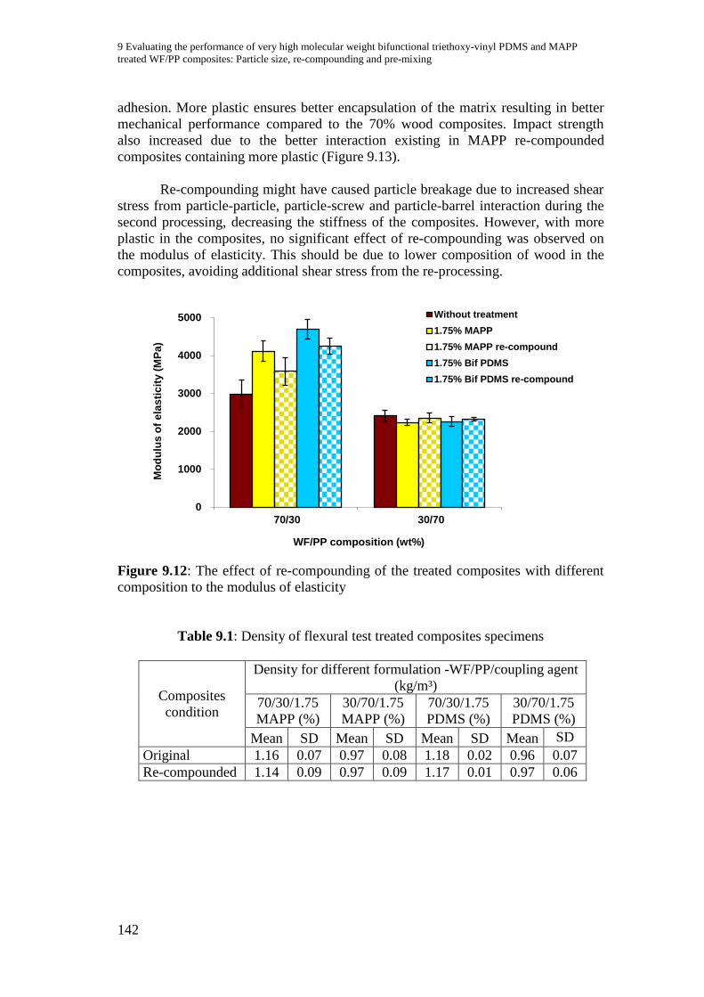
9 Evaluating the performance of very high molecular weight bifunctional triethoxy-vinyl PDMS and MAPP
treated WF/PP composites: Particle size, re-compounding and pre-mixing
142
adhesion. More plastic ensures better encapsulation of the matrix resulting in better
mechanical performance compared to the 70% wood composites. Impact strength
also increased due to the better interaction existing in MAPP re-compounded
composites containing more plastic (Figure 9.13).
Re-compounding might have caused particle breakage due to increased shear
stress from particle-particle, particle-screw and particle-barrel interaction during the
second processing, decreasing the stiffness of the composites. However, with more
plastic in the composites, no significant effect of re-compounding was observed on
the modulus of elasticity. This should be due to lower composition of wood in the
composites, avoiding additional shear stress from the re-processing.
Figure 9.12: The effect of re-compounding of the treated composites with different
composition to the modulus of elasticity
Table 9.1: Density of flexural test treated composites specimens
Composites
condition
Density for different formulation -WF/PP/coupling agent
(kg/m³)
70/30/1.75
MAPP (%)
30/70/1.75
MAPP (%)
70/30/1.75
PDMS (%)
30/70/1.75
PDMS (%)
Mean SD Mean SD Mean SD Mean SD
Original 1.16 0.07 0.97 0.08 1.18 0.02 0.96 0.07
Re-compounded 1.14 0.09 0.97 0.09 1.17 0.01 0.97 0.06
0
1000
2000
3000
4000
5000
70/30 30/70
Mo
du
lus
of
ela
sti
cit
y (
MP
a)
WF/PP composition (wt%)
Without treatment
1.75% MAPP
1.75% MAPP re-compound
1.75% Bif PDMS
1.75% Bif PDMS re-compound
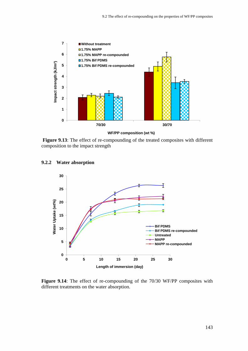
9.2 The effect of re-compounding on the properties of WF/PP composites
143
Figure 9.13: The effect of re-compounding of the treated composites with different
composition to the impact strength
9.2.2 Water absorption
Figure 9.14: The effect of re-compounding of the 70/30 WF/PP composites with
different treatments on the water absorption.
0
1
2
3
4
5
6
7
70/30 30/70
Imp
ac
t s
tre
ng
th (
kJ
/m²)
WF/PP composition (wt %)
Without treatment
1.75% MAPP
1.75% MAPP re-compounded
1.75% Bif PDMS
1.75% Bif PDMS re-compounded
0
5
10
15
20
25
30
0 5 10 15 20 25 30
Wa
ter
Up
tak
e (
wt%
)
Length of immersion (day)
Bif PDMS
Bif PDMS re-compounded
Untreated
MAPP
MAPP re-compounded

9 Evaluating the performance of very high molecular weight bifunctional triethoxy-vinyl PDMS and MAPP
treated WF/PP composites: Particle size, re-compounding and pre-mixing
144
Figure 9.15: The effect of re-compounding of the 70/30 WF/PP composites with
different treatments on the volume change.
Figure 9.16: The effect of re-compounding of the 30/70 WF/PP composites with
different treatments on the water absorption.
0
2
4
6
8
10
12
14
16
18
0 10 20 30
Vo
lum
e c
ha
ng
e (
%)
Length of immersion (day)
Bif PDMS
Bif PDMS re-compounded
Untreated
MAPP
MAPP re-compounded
0
2
4
6
8
10
12
14
16
18
0 10 20 30
Wa
ter
Up
tak
e (
wt%
)
Length of immersion (day)
Bif PDMS
Bif PDMS re-compounded
Untreated
MAPP
MAPP re-compounded
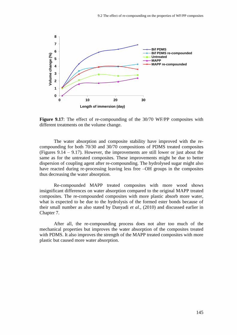
9.2 The effect of re-compounding on the properties of WF/PP composites
145
Figure 9.17: The effect of re-compounding of the 30/70 WF/PP composites with
different treatments on the volume change.
The water absorption and composite stability have improved with the re-
compounding for both 70/30 and 30/70 compositions of PDMS treated composites
(Figures 9.14 – 9.17). However, the improvements are still lower or just about the
same as for the untreated composites. These improvements might be due to better
dispersion of coupling agent after re-compounding. The hydrolysed sugar might also
have reacted during re-processing leaving less free –OH groups in the composites
thus decreasing the water absorption.
Re-compounded MAPP treated composites with more wood shows
insignificant differences on water absorption compared to the original MAPP treated
composites. The re-compounded composites with more plastic absorb more water,
what is expected to be due to the hydrolysis of the formed ester bonds because of
their small number as also stated by Danyadi et al., (2010) and discussed earlier in
Chapter 7.
After all, the re-compounding process does not alter too much of the
mechanical properties but improves the water absorption of the composites treated
with PDMS. It also improves the strength of the MAPP treated composites with more
plastic but caused more water absorption.
0
1
2
3
4
5
6
7
8
0 10 20 30
Vo
lum
e c
ha
ng
e (
%)
Length of immersion (day)
Bif PDMSBif PDMS re-compoundedUntreatedMAPPMAPP re-compounded
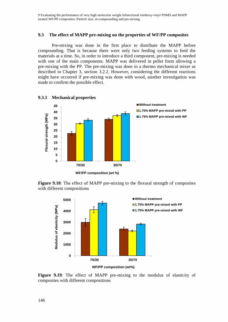
9 Evaluating the performance of very high molecular weight bifunctional triethoxy-vinyl PDMS and MAPP
treated WF/PP composites: Particle size, re-compounding and pre-mixing
146
9.3 The effect of MAPP pre-mixing on the properties of WF/PP composites
Pre-mixing was done in the first place to distribute the MAPP before
compounding. That is because there were only two feeding systems to feed the
materials at a time. So, in order to introduce a third component, pre-mixing is needed
with one of the main components. MAPP was delivered in pellet form allowing a
pre-mixing with the PP. The pre-mixing was done in a thermo mechanical mixer as
described in Chapter 3, section 3.2.2. However, considering the different reactions
might have occurred if pre-mixing was done with wood, another investigation was
made to confirm the possible effect.
9.3.1 Mechanical properties
Figure 9.18: The effect of MAPP pre-mixing to the flexural strength of composites
with different compositions
Figure 9.19: The effect of MAPP pre-mixing to the modulus of elasticity of
composites with different compositions
0
5
10
15
20
25
30
35
40
45
70/30 30/70
Fle
xu
ral s
tren
gth
(M
Pa
)
WF/PP composition (wt %)
Without treatment
1.75% MAPP pre-mixed with PP
1.75% MAPP pre-mixed with WF
0
1000
2000
3000
4000
5000
70/30 30/70
Mo
du
lus
of
ela
sti
cit
y (
MP
a)
WF/PP composition (wt%)
Without treatment
1.75% MAPP pre-mixed with PP
1.75% MAPP pre-mixed with WF
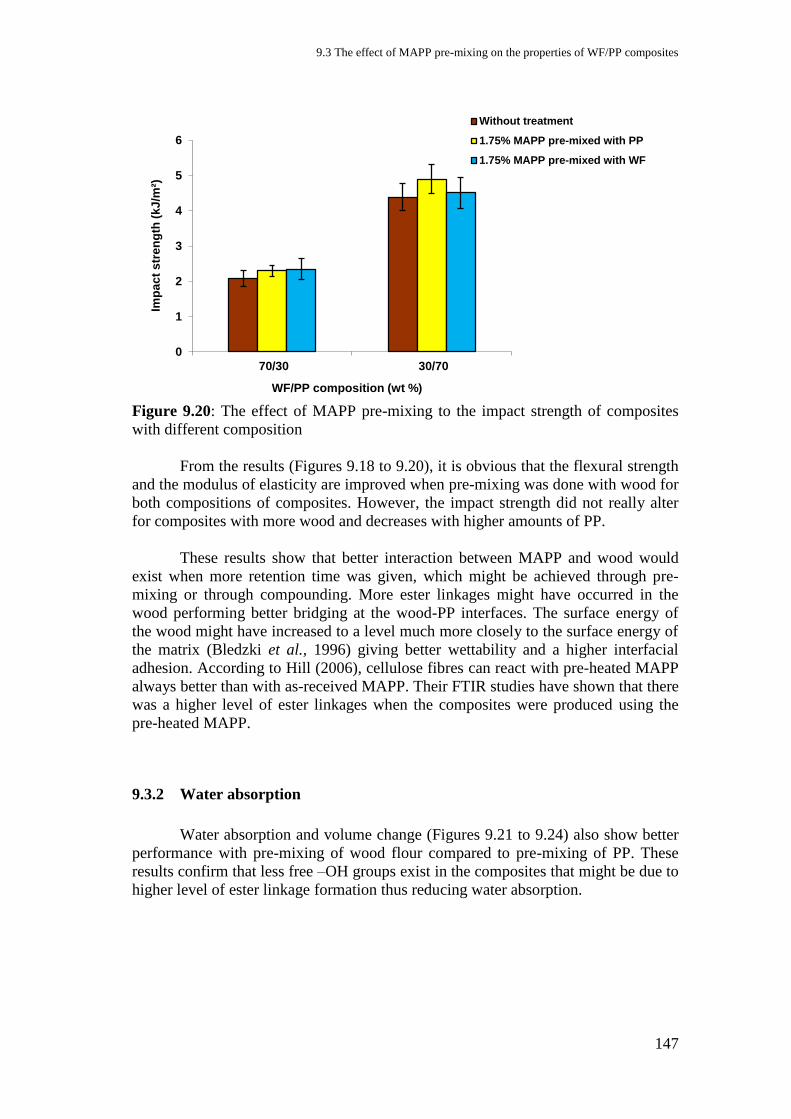
9.3 The effect of MAPP pre-mixing on the properties of WF/PP composites
147
Figure 9.20: The effect of MAPP pre-mixing to the impact strength of composites
with different composition
From the results (Figures 9.18 to 9.20), it is obvious that the flexural strength
and the modulus of elasticity are improved when pre-mixing was done with wood for
both compositions of composites. However, the impact strength did not really alter
for composites with more wood and decreases with higher amounts of PP.
These results show that better interaction between MAPP and wood would
exist when more retention time was given, which might be achieved through pre-
mixing or through compounding. More ester linkages might have occurred in the
wood performing better bridging at the wood-PP interfaces. The surface energy of
the wood might have increased to a level much more closely to the surface energy of
the matrix (Bledzki et al., 1996) giving better wettability and a higher interfacial
adhesion. According to Hill (2006), cellulose fibres can react with pre-heated MAPP
always better than with as-received MAPP. Their FTIR studies have shown that there
was a higher level of ester linkages when the composites were produced using the
pre-heated MAPP.
9.3.2 Water absorption
Water absorption and volume change (Figures 9.21 to 9.24) also show better
performance with pre-mixing of wood flour compared to pre-mixing of PP. These
results confirm that less free –OH groups exist in the composites that might be due to
higher level of ester linkage formation thus reducing water absorption.
0
1
2
3
4
5
6
70/30 30/70
Imp
ac
t s
tre
ng
th (
kJ
/m²)
WF/PP composition (wt %)
Without treatment
1.75% MAPP pre-mixed with PP
1.75% MAPP pre-mixed with WF

9 Evaluating the performance of very high molecular weight bifunctional triethoxy-vinyl PDMS and MAPP
treated WF/PP composites: Particle size, re-compounding and pre-mixing
148
Figure 9.21: The effect of 1.75% MAPP pre-mixing to the water absorption of 70/30
WF/PP composites.
Figure 9.22: The effect of 1.75% MAPP pre-mixing to the volume change of 70/30
WF/PP composites.
0
5
10
15
20
25
0 5 10 15 20 25 30
Wate
r U
pta
ke (
wt%
)
Length of immersion (day)
PP pre-mixed
WF pre-mixed
Untreated
0
2
4
6
8
10
12
14
16
18
0 5 10 15 20 25 30
Vo
lum
e c
han
ge (
%)
Length of immersion (day)
PP pre-mixed
WF pre-mixed
Untreated
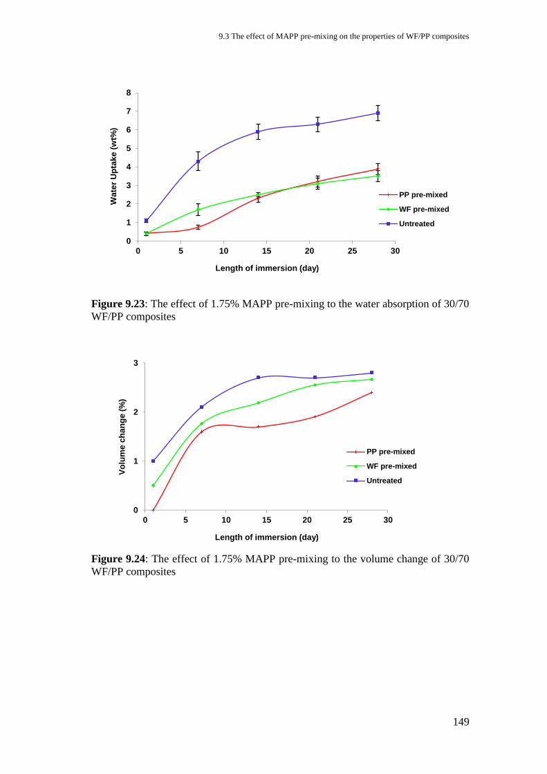
9.3 The effect of MAPP pre-mixing on the properties of WF/PP composites
149
Figure 9.23: The effect of 1.75% MAPP pre-mixing to the water absorption of 30/70
WF/PP composites
Figure 9.24: The effect of 1.75% MAPP pre-mixing to the volume change of 30/70
WF/PP composites
0
1
2
3
4
5
6
7
8
0 5 10 15 20 25 30
Wa
ter
Up
tak
e (
wt%
)
Length of immersion (day)
PP pre-mixed
WF pre-mixed
Untreated
0
1
2
3
0 5 10 15 20 25 30
Vo
lum
e c
ha
ng
e (
%)
Length of immersion (day)
PP pre-mixed
WF pre-mixed
Untreated
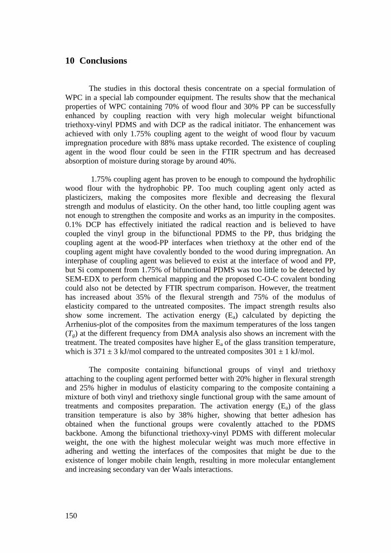
150
10 Conclusions
The studies in this doctoral thesis concentrate on a special formulation of
WPC in a special lab compounder equipment. The results show that the mechanical
properties of WPC containing 70% of wood flour and 30% PP can be successfully
enhanced by coupling reaction with very high molecular weight bifunctional
triethoxy-vinyl PDMS and with DCP as the radical initiator. The enhancement was
achieved with only 1.75% coupling agent to the weight of wood flour by vacuum
impregnation procedure with 88% mass uptake recorded. The existence of coupling
agent in the wood flour could be seen in the FTIR spectrum and has decreased
absorption of moisture during storage by around 40%.
1.75% coupling agent has proven to be enough to compound the hydrophilic
wood flour with the hydrophobic PP. Too much coupling agent only acted as
plasticizers, making the composites more flexible and decreasing the flexural
strength and modulus of elasticity. On the other hand, too little coupling agent was
not enough to strengthen the composite and works as an impurity in the composites.
0.1% DCP has effectively initiated the radical reaction and is believed to have
coupled the vinyl group in the bifunctional PDMS to the PP, thus bridging the
coupling agent at the wood-PP interfaces when triethoxy at the other end of the
coupling agent might have covalently bonded to the wood during impregnation. An
interphase of coupling agent was believed to exist at the interface of wood and PP,
but Si component from 1.75% of bifunctional PDMS was too little to be detected by
SEM-EDX to perform chemical mapping and the proposed C-O-C covalent bonding
could also not be detected by FTIR spectrum comparison. However, the treatment
has increased about 35% of the flexural strength and 75% of the modulus of
elasticity compared to the untreated composites. The impact strength results also
show some increment. The activation energy (Ea) calculated by depicting the
Arrhenius-plot of the composites from the maximum temperatures of the loss tangen
(Tg) at the different frequency from DMA analysis also shows an increment with the
treatment. The treated composites have higher Ea of the glass transition temperature,
which is 371 ± 3 kJ/mol compared to the untreated composites 301 ± 1 kJ/mol.
The composite containing bifunctional groups of vinyl and triethoxy
attaching to the coupling agent performed better with 20% higher in flexural strength
and 25% higher in modulus of elasticity comparing to the composite containing a
mixture of both vinyl and triethoxy single functional group with the same amount of
treatments and composites preparation. The activation energy (Ea) of the glass
transition temperature is also by 38% higher, showing that better adhesion has
obtained when the functional groups were covalently attached to the PDMS
backbone. Among the bifunctional triethoxy-vinyl PDMS with different molecular
weight, the one with the highest molecular weight was much more effective in
adhering and wetting the interfaces of the composites that might be due to the
existence of longer mobile chain length, resulting in more molecular entanglement
and increasing secondary van der Waals interactions.
10 Conclusions
151
The performance of composites treated with very high molecular weight
bifunctional triethoxy-vinyl PDMS was also comparable with the performance of
industrially established MAPP coupling agent. The flexural strength was more or less
the same but the stiffness was about 20% higher and with only 3.6% difference in the
activation energy. Overall, we can optically see the microstructural quality of the
bifunctional PDMS treated composites being homogenous with good wetting and
voids hardly detectable. However, even though the mechanical properties were
improved, the water absorption of the treated composites also increased. The 70/30
WF/PP composites treated with the commercial MAPP as well shows the same
results. Processing with the small extrusion compounder is believed to be one of the
causes, due to the very low retention time during compounding, that has hindered
some of the coupling agent to react completely. Hydrolysis was believed to occur in
the composites. Hydrolysis of the formed ester bond might have occurred with
MAPP treatment and hydrolysis of polysaccharides occurred in the bifunctional
PDMS treatment. Both lead to increase the free OH-group in the composites that
tend to absorb more water compared to the untreated composites. The sugar analysis
has proven that the treated composites contained 48% more free sugar.
Treatment of the wood by vacuum impregnation with PDMS solution was
found to be the most effective way of applying the very high molecular weight
bifunctional triethoxy-vinyl PDMS compared to the surface spraying of PDMS
emulsions or direct compounding the ready compounded PDMS-PP. This seems to
be due to longer contact time between the wood and PDMS has led to a better
reaction.
A loading of 70% of wood flour into the PP with good adhesion could reduce
cost and increase use of the WPC. However a ratio of 50/50 WF/PP composition was
found to give better characteristics. Depending on the field of use the bifunctional
PDMS treated composites composition could be tailored to give better performance.
They could also be reprocessed without loss of the performance and characteristic
moreover improving water absorption.
Further investigation should be done to investigate the effectiveness of very
high molecular weight bifunctional triethoxy-vinyl PDMS as coupling agents in
WF/PP composites. The following study is suggested for further understanding on
the role-plays by this coupling agent in bridging the composites' interfaces:
The effect of pH value on the coupling reaction. In which condition the
coupling reaction could be controlled?
The effect of different processing conditions in producing WF/PP composites.
What happen if the composites are produced using a bigger scale extrusion
compounding process? Will the same characteristics remain?
The effect of bifunctional PDMS coupling reaction on the hydrolysis of
polysaccharides in wood and the relationship between the hemicellulose
content to the amount of free sugar in the composites. What factors contribute
to the hydrolysis reaction and what is the critical limit to avoid hydrolysis?
152
References
Acha, B.A., Reboredo, M.M., Marcovich, N.E. 2007. Creep and dynamic mechanical
behavior of PP–jute composites: Effect of the interfacial adhesion. Composites:
Part A. Vol. 38: 1507–1516
Allen, K.W. 1992. Silanes as the interphase in adhesive bonds in Silanes and other
coupling agents. Edited by Mittal, K.L. VSP. BV. Netherlands: 81-90.
Arkles, B. 2004. Silane Coupling Agents: Connecting Across Boundaries in Silicon
Compounds: Silanes and Silicones. Gelest Catalog 3000 – A. Edited by Arkles
B. and Larson, G. Gelest, Inc., Morrisville, PA. 165-186
Arkles, B., Steinmetz, J.R., Zazyczny, J. and Mehta, P. 1992. Factors contributing to
stability of alkoxyysilanes in aqueous solution in Silanes and other coupling
agents. Edited by Mittal, K. L. VSP. BV. Netherlands: 91-104.
Ashori, A. and Nourbakhsh, A. 2010. Reinforced polypropylene composites: Effects
of chemical compositions and particle size. Bioresource Technology, Vol. 101
(7): 2515-2519.
Azizi, H. and Ghasemi, I. 2004. Material Properties. Reactive extrusion of PP:
production of controlled rheology PP (CRPP) by peroxide promotion
degradation. Polymer Testing. Vol. 23: 137-143.
Azizi, H. and Ghasemi, I. 2005. Investigation on Influence of Peroxide gradation
Process on Rheological Properties of Polypropylene. Iranian Polymer Journal.
Vol. 14 (5): 465-471.
Azizi, H., Ghasemi, I. and Karrabi, M. 2008. Controlled-peroxide degradation of
polypropylene: Rheologycal properties and prediction of MWD from
rheological data. Polymer Testing. Vol. 27: 548-554.
Baeza, J. and Freer, J. 2001. Chemical characterization of wood and its components
in Wood and cellulosic chemistry 2nd
ed. Revised and expanded. Edited by Hon,
D.N.S and Shiraishi, N. Marcel Dekker inc, New York: 275-384
Bash T.F. and Karian H.G. 2003. Functionalization and compounding of PP using
twin-screw extruders in Handbook of PP and PP composites 2nd
ed. edited by
Karian, H.G. Marcel Dekker, Inc. New York.
Bataille, P., Allard, P., Cousin, P. and Sapieha, S. 1990. Interfacial phenomena in
cellulose/polyethylene composites. Polymer Composites. Vol. 11(5): 301-304.
Beck,D. L., Hiltz, A. A., and Knox, J. R. 1968. Glass Transitions in Polypropylene
SPE Transactions. Vol. 3: 279.

References
153
Bengtsson, M. and Oksman, K. 2006. The Use of Silane Technology in Crosslinking
Polyethylene/Wood Flour Composites. Composites: Part A. Vol. 37. 752 – 765
Bengtsson, M., Oksman, K. and Stark, N.M. 2006. Profile Extrusion and Mechanical
Properties of Crosslinked Wood – Thermoplastic Composites. Polymer
Composites. 184 -194.
Bengtsson, M., Stark, N.M and Oksman, K. 2007. Durability and mechanical
properties of cross-linked wood thermoplastic composites. Composites Science
and Technology. Vol. 67. 2728 – 2738.
Biron, M. 2007. Thermoplastics and thermoplastic composites. Technical
information for plastics users. Butterworth-Heinemann-Elsevier, Burlington
MA.
Bledzki, A.K. and Farouk, O. (2003) Wood Fibre Reinforced Polypropylene
Composites: Effect of Fibre Geometry and Coupling Agent on Physico-
Mechanical Properties. Applied Composite Materials. Vol. 10: 365–379.
Bledzki, A.K. and Gassan, J. 1999. Composite reinforced with cellulose-based fibres.
Prog. Polym. Sci. Vol. 24: 221-274.
Bledzki, A.K., Letman, M., Viksne, A., Rence, L., 2005. A comparison of
compounding processes and wood type for wood fibre–PP composites.
Composites Part A. Vol. 36 (6), 789–797.
Bledzki, A.K., Reihmane, S. and Gassan, J. 1996. Properties and Modification
Methods for Vegetable Fibres for Natural Fibre Composites. Journal of Applied
Polymer Science. Vol. 59 (8): 1329-1336.
Bremner, T. and Rudin, A. (1993) Peroxide modification of linear low-density
polyethylene: A comparison of dialkyl peroxides. Journal of Applied Polymer
Science. Vol. 49(5): 785–798.
Brydson, J.A. 1999. Plastic Materials. Oxford: Butterworth-Heinemann.
Carus, M. 2011. Wood plastic composites march toward 15% pa growth in Europe.
Technical Articles & Reports on Plastic Industry. March 14, 2011. Online:
http://www.plastemart.com/technical-market-reports-plastics-industry.asp
Chakrabarty, S., Zhang, X., Bharti, P., Chujo, Y., Miyake, J., Wynne, K.J. and
Yadavalli,V.K. 2010. Processing dependence of surface morphology in
condensation cured PDMS nanocomposites. Polymer. Vol. 51(24): 5756-5763.
Chanda, M. and Roy, S.K. 2006. Plastic Technology Handbook. 4th
ed. Taylor and
Francis group, LLC, CRC Press USA: 1-24, 1-108
References
154
Chowdhury, M.J.A. and Wolcott, M.P. 2007. Compatibilizer selection to improve
mechanical and moisture properties of extruded wood-HDPE composites.
Forest Prod. J. Vol.57(9):46-53.
Clemons, C.M. 2000. Wood fibre-plastic composites in the United States – history
and current and future markets. 3rd
International wood and natural fibre
composites symposium. Kassel, Germany: 1-7.
Clemons, C.M. and Caufield, D.F. 2005. Wood Flour in Functional fillers for
plastics. Edited by Xanthos, M. Wiley-VCH Verlag GmbH & Co. Kga,
Weinheim: 249-270.
Clemons, C. 2008. Raw materials for wood polymer composites in Wood-polymer
composites. Edited by Niska, K.O. and Sain, M. Woodhead Publishing Limited,
Cambridge, England and CRC Press LLC, USA: 1-22.
Clemons, C. 2010. Elastomer modified polypropylene–polyethylene blends as
matrices for wood flour–plastic composites. Composites: Part A. Vol. 41:
1559–1569.
Constable, R. C. 1994. Evaluation of Chemically Modified Polypropylene with
Various Glass Fibre Types, for Performance Enhancement in Glass Filled
Polypropylene. SPE-ANTEC Tech.Papers: 127-130.
Constable, R. C., Roberts, D. H. and Thiruvengada, S. 1997. Advances in Maleated
Polyolefins for Plastics Applications. Polym. Eng. Sci.Vol. 37: 1421-1426.
Dalvag, H., Klason, C. and Stromvall. H.E. 1985. The efficiency of cellulose fillers
in common thermoplastics: Filling with processing aids and coupling agents.
Inter. J. Polym. Mater. Vol.11:9-38.
Danyadi, L., Janecska, T., Szabo, Z., Nagy, G., Moczo, J. and Pukanszky, B. 2007.
Wood flour filled PP composites: Compatibilization and adhesion. Composites
Science and Technology. Vol. 67: 2838–2846
Danyadi, L., Moczo, J. and Pukanszky, B. 2010. Effect of various surface
modifications of wood flour on the properties of PP/wood composites.
Composites: Part A. Vol. 41: 199–206.
Das, S., Sara, A.K., Choudhury, P.K., Basak, R.K., Mitra, B.C., Todd, T., Lang, S.,
2000. Effect of steam pre-treatment of jute fibre on dimensional stability of jute
composite. Applied Polymer Science. Vol. 76 (11), 1652–1661.
De Poortere. M. 2005. The markets for silicones in Organosilicon Chemistry VI
From Molecules to Materials. Edited by Auner, N. and Weis, J. WILEY-VCH
Verlag GmbH, Weinheim: 610-619.
References
155
Edser, C. 2003. Bridging the gap with coupling agents. Polymer Additives and
Colors.
Onlline: www.specialchem4polymers.com/2456/eng/article.aspx?id=1355
Esteves, A.C.C., Brokken-Zijp, J., Laven, J. and de With, G. 2010. Light converter
coatings from cross-linked PDMS/particles composite materials. Progress in
Organic Coatings 68: 12–18
Fang, J., Kelarakis, A. Wang, D.,Giannelis, E.P. Finlay, J.A. Callow, M.E. and
Callow, J.A. 2010. Fouling release nanostructured coating based on PDMS-
polyurea segmented copolymers. Polymer. Vol. 51(12). 2636-2642.
Felix, J.M. and Gatenholm, P. 1991. The Nature of Adhesion in Composites of
Modified Cellulose Fibres and Polypropylene. Journal of Applied Polymer
Science. Vol. 42: 609-620.
Fen dinger, N. J. 2000. Polydimethylsiloxane (PDMS): Environmental fate and effect
in Organosilicon Chemistry IV From Molecules to Materials. Edited by Auner,
N. and Weis, J. WILEY-VCH Verlag GmbH, Weinheim: 626-638.
Gabott, P. 2008. A practical introduction to differential scanning calorimetry in
Principles and application of thermal analysis edited by Gabott, P. Blackwell
Publishing Ltd. UK: 36.
Gassan, J. and Bledzki, A.K. 2000. Possibilities to Improve the Properties of Natural
Fibre Reinforced Plastics by Fibre Modification – Jute Polypropylene
Composites. Applied Composite Materials. Vol. 7: 373–385.
Ghaemy, M. and Roohina, S. 2003. Grafting of Maleic Anhydride on Polyethylene in
homogeneous Medium in the presence of radical initiator. Iranian Polymer
Journal. Vol. 12 (1): 21-29.
Gironès, J., Pimenta M.T.B., Vilaseca F., de Carvalho A.F.J., Mutjé P. and Curvelo,
A.A.S. 2007. Blocked isocyanates as coupling agents for cellulose-based
composites. Polymers.Vol.68: 537-543
Goldsberry, C. 2009. WPC demand growth has healthy forecast. August 10th.
Online: http://www.plasticstoday.com/articles/wpc-demand-growth-has-
healthy-forecast
Gooch, J.W. 2007. Encyclopedia Dictionary of Polymers. Springer Science +
Business Media, LLC. USA: 23.
Gwon, J.G., Lee, S.Y., Chun, S.J., Doh, G.H. and Kim, J.H. 2010. Effects of
chemical treatments of hybrid fillers on the physical and thermal properties of

References
156
wood plastic composites. Composites Part A: Applied Science and
Manufacturing. Vol. 41(10): 1491-1497.
Hill, C.A.S. 2000. Wood plastic composites: strategies for compatibilising the
phases. Journal of the institute of wood science. Vol. 15 (3) (87): 140-146
Hill, C.A.S. 2006. Wood Modification Chemical, Thermal and Other Process. John
Wiley & Son, Ltd. England: 136, 149-173.
Hu, M., Wang, Z., Qu, B. and Hu, K. 2006. Vapour phase grafting of
vinyltrimethoxysilane and water crosslinking of polypropylene. Reactive and
Functional Polymers. Vol. 66. 287 – 296
Hull, D. 1995. An introduction to composite materials. Great Britain: University
Press Cambridge.
Ibhadon, A.O. 1998. Fracture mechanics of PP: Effect of molecular characteristic,
crystallization condition and annealing on morphology and impact
performance. J. Appl. Polym. Sci. Vol. 69 (13): 2657-2661
Ichazo, M.N., Albano, C., Gonzalez, J., Perera, R., Candal, M.V. 2001.
Polypropylene/Wood Flour Composite: Treatment and Properties. Composite
Structures. Vol. 54: 207 – 214.
Ishida, H. and Miller, J. D. 1984. Substrate effects on the chemisorbed and
physisorbed layers of methacryl silane modified particulate minerals.
Macromolecules. Vol. 17: 1659-1666.
Ishii, T. and Shimizu, K. 2001. Chemistry of Cell Wall Polysaccharides in Wood and
cellulosic chemistry 2nd
ed. Revised and expanded. Edited by Hon, D.N.S and
Shiraishi, N. Marcel Dekker Inc, New York: 175-212.
Ishikawa, K. and Yatsuyanagi, F. 2000. Modified polysiloxanes, rubber compositions
and tire tread rubber compositions containing the same and reactive
plasticizers. United States Patent no: 6 140 450.
IUPAC Compendium of chemical terminology. 2007. Online:
http://www.iupac.org/goldbook/DT07266.pdf
Jahangir, M., Chowdhury, A. and Wolcott, M.P. 2007. Compatibilizer selection to
improve mechanical and moisture properties of extruded wood-HDPE
composites. Forest product journal. Vol. 57(9): 46-53.
Jarrigeon, M., Chabert, B., Chatain, D., Lacabanne, C. and Nemoz G. 1980. Multiple
transitions in isotactic polypropylene around and above the glass transition.
Journal of Macromolecular Science, Part B. Vol. 17(1): 1-24.
References
157
Jiang, H. and Kamdem, D.P. 2004. Development of Poly (vinyl chloride)/Wood
Composites. A Literature Review. Jour. of vinyl & additive tech. Vol. 10(2):
59-69.
Kallio, M. 2005. The elastic and damping properties of magnetorheological
elastomers. VTT Publication 565. Finland: 38.
Kang, H.J., Meesiri W., Blum, F.D. 1990. NMR studies of the hydrolysis and
molecular motion of aminopropylsilane. Mater Sci Eng A. Structure. Vol. 126:
265-70.
Karmarkar, A., Chauhan, S.S., Modak, J.M., and Chanda, M. 2007. Mechanical
properties of wood–fibre reinforced polypropylene composites: Effect of a
novel compatibilizer with isocyanate functional group. Composites: Part A.
Vol. 38: 227-233.
Kent, R. 2005. Above board. Wood plastic composites. Materials world. Vol 13. (1).
Online: http://www.tangram.co.uk/Tangram-Publications.html
Klyosov, A. A. 2007. Wood Plastic Composites. New Jersey: Wiley Interscience.
LeGault, M.R. 2009. Raising the bar on WPC durability. Composites Technology.
December. Online: http://www.compositesworld.com/articles/ct
Li, S.Y., Srivastava, R. and Parnas, R.S. 2010. Separation of 1-butanol by
pervaporation using a novel tri-layer PDMS composite membrane. Journal of
Membrane Science. Vol. 363(1-2): 287- 294.
Lopes, P. E. and Sousa J. A. 2001. Influence of Interphase Characteristics on
Mechanical Properties of Polypropylene/Glass Fibre Composites with PP-g-
MAH Interfacial Compatibilizer, SPE-ANTEC Tech. Papers: 1359-1365
Lu, J.Z., Wu, Q. and McNabb, Jr. H.S. 2000. Chemical Coupling in Wood Fibre and
Polymer Composites: A Review of Coupling Agents and Treatments. Wood
and Fibre Sciences. Vol. 32(1): 88-104.
Ma, P.C., Siddiqui, N.A., Marom, G. and Kim, J.K. 2010. Dispersion and
functionalization of carbon nanotubes for polymer-based nanocomposites: A
review. Composites Part A: Applied Science and Manufacturing. Vol. 41(10):
1345-1367
Maier, C and Calafut, T. 1998. Polypropylene The Definitive User’s Guide and
Databook Plastics Design Library.USA: 3-25
McLoughlin, K. M., and Elliot, S. J. Properties of Glass-Filled Polypropylene,
Nylon 6, and Polypropylene/Nylon 6 Alloys Compatibilized Using PP-g-MA,
SPE-ANTEC Tech. Papers: 1561-1570.
References
158
Maldas, D. and Kokta, B.V. 1991. Influence of organic peroxide on the performance
of maleic anhydride coated cellulose fibre filled thermoplastic composites.
Polym. J. Vol. 23(10): 1163-1171.
Maldas, D. and Kokta, B.V. 1994. Role of coupling agent on the performance of
wood flour filled polypropylene composites. Intern. J. Polymeric Mater. Vol.
27: 77-88.
Mani, S., Cassagnau, P., Bousmina, M. and Chaumont, P. 2010. Rheological
modelling of the free-radical crosslinking of PDMS rubber in the presence of
TEMPO nitroxide. Polymer. Vol. 51 (17): 3918-3925.
Maxwell, R.S., Chinn, S.C., Alviso, C.T., Harvey, C.A. Giuliani, J.R., Wilson, T.S.
and Cohenour. R. 2009. Quantification of radiation induced crosslinking in a
commercial, toughened silicone rubber, TR55 by 1H MQ-NMR. Polymer
Degradation and Stability. Vol. 94 (3): 456-464.
Menard, K. P. 2008. Dynamic mechanical analysis. A practical introduction. 2nd
ed.
CRC Press Taylor & Francis Group. New York.
Myers, G.E., Chahyadi, I.S., Coberly, C.A. and Ermer, D.S. 1991. Wood
flour/polypropylene composites: influence of maleated pp and process and
composition variables on mechanical properties. Intl. J. Polymeric Matter. Vol.
15: 21-44.
Miller, A.C. and Berg, J.C. 2003. Effect of silane coupling agent adsorbate structure
on adhesion performance with a polymeric matrix. Compos Part A. Applied
Science and Manufacturing. Vol. 34: 327-32.
Miller, R. B. 1999. Structure of wood in Wood Handbook. Wood as an Engineering
Material by Wisconsin, M. USDA Forest Service, Forest Product Laboratory
US: 1-4.
Milton, G.W. 2004. The theory of composites. Cambridge university press UK: 1-5
Moad, G. and Solomon, D.H. 2006. The chemistry of radical polymerisation 2nd
fully
revised ed. Elsevier LTD. UK: 333-335.
Mokoena, M. A., Djokovic, V. and Luyt, A. S. 2004. Composites of linear low-
density polyethylene and short sisal fibres: The effects of peroxide treatment.
Journal of Materials Science. Vol. 39: 3403-3412
Nachtigall, S. M. B., Cerveira, G. S. and Rosa S. M. L. 2007. New polymeric-
coupling agent for polypropylene/wood-flour composites. Polymer Testing.
Vol. 26: 619-628.
References
159
Nachtigall, S. M. B., Stedile, F. C., Felix, A. H. O. and Mauler, R. S. 1999.
Polypropylene Functionalization with vinyltriethoxysilane. Journal of Applied
Polymer Science. Vol. 72: 1313 – 1319.
Navoroj, S., Culler, R., Koenig, J.L. and Ishida, H. 1984. Structure and adsorption
characteristics of silane coupling agents on silica and E-glass fibre; dependence
on pH. J. Colloid Inter. Sci. Vol. 97(2): 309-317.
Nielsen, L. E. & Landel, R. F. 1994. Mechanical properties of polymers and
composites. New York: Marcel Dekker Inc.
Nishino, T. 2004. Natural fibre sources in Green Composites Polymer Composites
and the Environment. Edited by Baillie, C. Woodhead Publishing Limited,
Cambridge, England and CRC Press LLC: 49-80.
Niska, K. O. and Sain, M. 2008. Introduction in Wood-polymer composites. Edited
by Niska, K.O. and Sain, M. Woodhead Publishing Limited, Cambridge,
England and CRC Press LLC, USA: xv.
Niska, K. O. and Sanadi A. R. 2008. Interaction between wood and synthetic
polymers in Wood-polymer composites. Edited by Niska, K.O. and Sain, M.
Woodhead Publishing Limited, Cambridge, England and CRC Press LLC,
USA: 41-71
Oksman, K. et. al. 1998. Mechanical properties and morphology of impact modified
polypropylene-wood flour composites. J. Appl. Polym. Sci. Vol. 67(9): 1503-
1513.
Optimat, L. and Merl, L. 2003. Wood plastic composites study – technologies and
UK market opportunities. Plastic research report. The Old Academy.UK:1-82.
Parbhoo, B., O’Hare, L.-A. and Leadley, S.R. 2002. Fundamental aspects of
adhesion technology in silicones in Adhesion science and engineering –2.
Surfaces, chemistry and applications. Edited by Chaudhury, M. Elsevier
Science B. V. The Netherlands: 677-709.
Park, J.M., Kim, P.G., Jang J.H., Wang, Z., Hwang, B.S. and DeVries, K.L. 2008.
Interfacial evaluation and durability of modified Jute fibres/polypropylene (PP)
composites using micromechanical test and acoustic emission. Composites:
Part B. Vol. 39: 1042–1061.
Parks, C.R. and Lorenz, O. 1961. Crosslinking Efficiency in the Reaction of Dicumyl
Peroxide with Dimethylactadiene. Jour. of Polym Sci. Vol. L: 287-298.
Patnaik, P. 2004. Dean’s Analytical Chemistry Handbook. 2nd
ed. McGraw-Hill
Handbook. New York: 15.4.
References
160
Piao, C., Winandy, J. E. and Shupe, T. F. 2010. From hydrophilic to hydrophobicity:
A critical review: Part I. Wettability and surface behaviour. Wood and Fibre
Science. Vol. 42(4): 1-21
Pickering, K.L., Abdalla, A., Ji, C., McDonald, A.G. and Franich, R.A. 2003. The
effect of silane coupling agents on radiata pine fibre for use in thermoplastic
matrix composites. Composites: Part A. Vol. 34: 915-926
Pvitchavd, G. 1998. Plastics Additives. An A-Z reference. Chapman & Hall, London:
12.
Pizzi, A. 1994. Advanced wood adhesives technology. Marcel Dekker, Inc. New
York: 2-18
Pizzi, A. 2005. Wood adhesives – basics in Handbook of Adhesion. Second Edition.
Edited by Packham, D.E. John Wiley & Sons, Ltd. UK: 603-608.
Pizzi, A. 2005a. Wood adhesives – isocyanates/urethanes in Handbook of Adhesion.
Second Edition. Edited by Packham, D.E. John Wiley & Sons, Ltd. UK: 609-
612.
Plueddemann, E.P. 1992. Reminiscing on silane coupling agents in Silanes and other
coupling agents. Edited by Mittal, K.L. VSP BV, The Netherlands: 3-19.
Pukanszky, B. 2005. Review. Interfaces and interphase in multicomponent material:
past, present, future. European Polymer Journal. Vol. 41: 645-662.
Qiu, W., Zhang, F. Endo, T. and Hirotsu, T. 2005. Isocyanate as a compatibilizing
agent on the properties of highly crystalline cellulose/polypropylene
composites. Journal of materials science. Vol. 40: 3607-3614.
Raj, R.G., Kokta, B.V., Maldas, D. and Daneault, C. 1989. Use of Wood Fibres in
Thermoplastic. VII. The Effect of Coupling Agents in polyethylene Wood
Fibre Composites. Journal of Applied Polymers Science. Vol. 37. 1089 -1103.
Reetz, I., Yagci, Y. and Mishra, M. K. 2009. Initiation of Vinyl Polymerization by
Organic Molecules and Nonmetal Initiators in Handbook of Vinyl Polymers
Radical Polymerization, Process, and Technology. 2nd ed. Edited by Mishra,
M. K. and Yagci, Y. Taylor & Francis Group, LLC. New York: 25-47.
Renner, K., Keny, C., Mcz, J. and Pukanszky, B. 2010. Micromechanical
deformation processes in PP/wood composites: Particle characteristics,
adhesion, mechanisms. Composites: Part A. Vol. 41: 1653–1661.
Saheb, D.N. and Jog, J.P. 1999. Natural fibre polymer composite: A review. Adv. In
Polym. Tech. Vol.18 (4): 351-363.

References
161
Sapieha, S., Allard, P. and Zhang, Y. H. 1990. Dicumyl Peroxide-Modified
Cellulose/LLDPE Composites. Journal of Applied Polymer Science. Vol. 41:
2039-2048
Simpson, W. and TenWolde, A. 1999. Physical properties and moisture relations of
wood in Wood Handbook. Wood as an Engineering Material by Madison,
Wisconsin.US: USDA Forest Service, Forest Product Laboratory. Chapter 3: 1-
25.
Sjöström, E. 1981. Wood chemistry fundamental and applications. Academic Press
Inc, New York.
Sombatsompop, N. and Chaochanchaikul, K. 2005. Average Mixing Torque, Tensile
and Impact Properties and Thermal Stability of Poly (vinyl chloride)/Sawdust
Composite with Different Silane Coupling Agents. Journal of Applied Polymer
Science. Vol. 96: 213-221.
SpecialChem. Adhesion Guide. Adhesion theory – Basic of adhesion. Online:
http://www.specialchem4adhesives.com/resources/adhesionguide/index.aspx?i
d=theory
Specialchem4polymers. Adhesion promoter centre. Coupling agent mechanisme.
Online:http://www.specialchem4polymers.com/tc/adhesion-
promoters/index.aspx?id=3307
Stark, N.M. and Berger, M.J. 1997. Effect of Particle Size on Properties of Wood-
Flour Reinforced Polypropylene Composites. Fourth International Conference
on Wood fibre-Plastic Composites. Forest Products Society Madison,
Wisconsin: 134-143.
Tangram. 2002. Wood plastic composites. A technical review of materials, processes
and applications. Tangram Technology Ltd. UK. Online:
www.tangram.co.uk/TI-Wood_Plastic_Composites_-_A%20Review_Paper.html
Tesoro, G, and Wu, Y. 1992. Silanes coupling agents: the role of the
organofunctional group in Silanes and other coupling agents. Edited by Mittal,
K. L. VSP. BV. Netherlands: 215-228.
The glass transition. Online (17.07.2011) :
http://www.pslc.ws/macrog/tg.htm#freevolume
Todd, D.B. 2005. Mixing of Fillers with Plastics in Functional Filler for Plastic
Edited by M. Xanthos. Weinheim: WILEY-VCH Verlag GmbH & Co KGaA:
39-55.
Tolinski, M. 2009. Additives for polyolefin. Getting the most out of PP, PE and TPO.
Elsevier Inc. USA: 217.
References
162
Ulbricht, M. 2006. Advanced functional polymer membranes. Polymer. Vol. 47:
2217–2262.
Weissenbach, K. and Mack, H. 2005. Silane Coupling Agents in Functional Filler
for Plastic Edited by M. Xanthos. Weinheim: WILEY-VCH Verlag GmbH &
Co KGaA: 59-83
Witucki, G. L. 1993. A silane Primer: Chemistry application of alkoxy silanes. A
Journal of coatings technology reprint. Online:
www.dowcorning.com/content/publishedlit/25-507-01.pdf
Wolcott, M.P. 2001. Wood plastic composite. Encyclopedia of materials: Science
and technology. Elsevier Science Ltd.: 9759-9763.
Wu, J., Yu, D., Chan, C.M. Kim, J., Mai, Y.W. 2000. Effect of Fiber pretreatment
Condition on the Interfacial Strength and Mechanical Properties of Wood
Fiber/PP Composites. Journal of Applied Polymer Science. Vol. 76: 1000-
1010.
Wypych, G. 2004. Handbook of plasticizers. ChemTec Publishing. Toronto-New
York: 59.
Xie, Y., Hill, C.A.S., Xiao, Z., Militz, H. and Mai. C. 2010. Silane coupling agents
used for natural fibre/polymer composites: A review. Composites Part A:
Applied Science and Manufacturing. Vol. 41(7): 806-819.
Yang, H.S., Kim H.J., Park H.J., Lee, B.J., Hwang, T.S. 2006. Water absorption
behavior and mechanical properties of lignocellulosic filler–polyolefin bio-
composites. Composite Structures. Vol. 72: 429-437.
Zhang, C., Li, K and Simonsen, J. 2006. Terminally Functionalized Polyethylenes as
Compatibilizers for Wood–Polyethylene Composites. Polymer engineering and
science. 108-113.
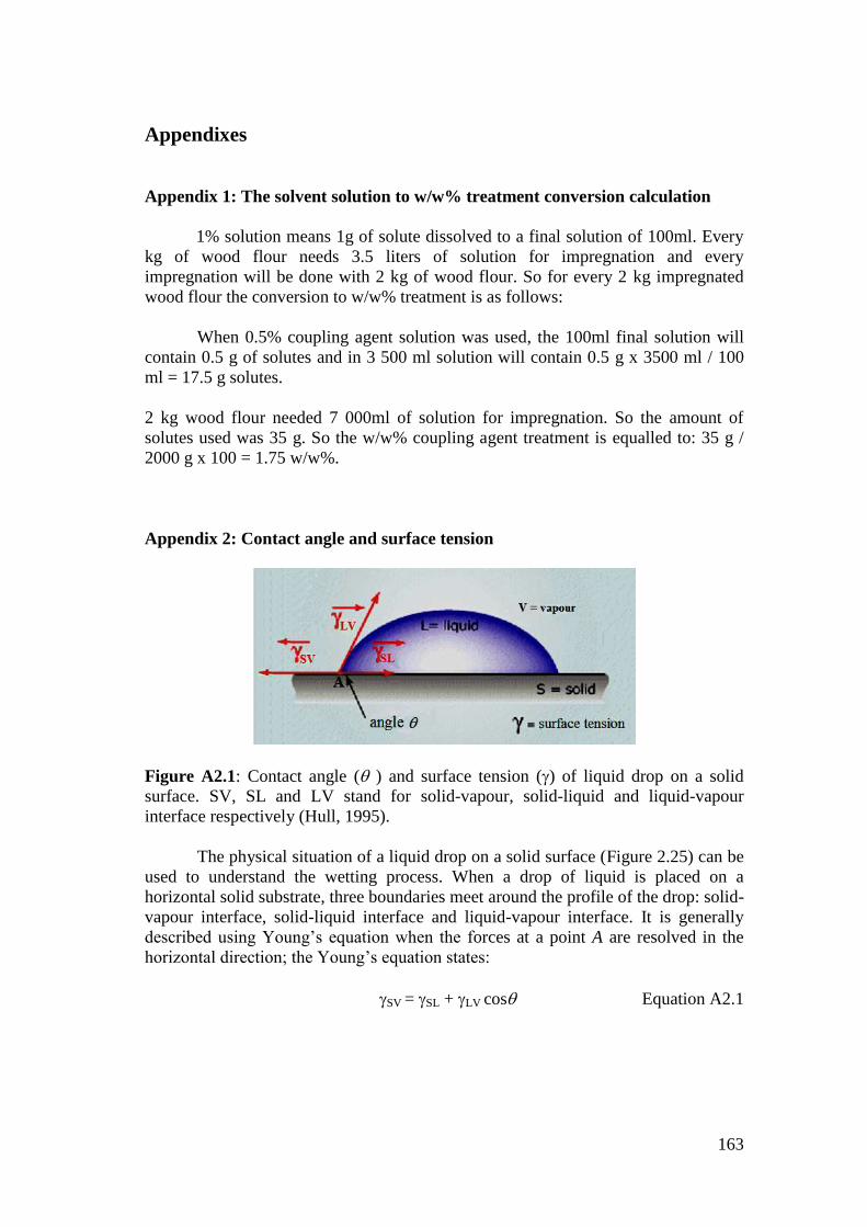
163
Appendixes
Appendix 1: The solvent solution to w/w% treatment conversion calculation
1% solution means 1g of solute dissolved to a final solution of 100ml. Every
kg of wood flour needs 3.5 liters of solution for impregnation and every
impregnation will be done with 2 kg of wood flour. So for every 2 kg impregnated
wood flour the conversion to w/w% treatment is as follows:
When 0.5% coupling agent solution was used, the 100ml final solution will
contain 0.5 g of solutes and in 3 500 ml solution will contain 0.5 g x 3500 ml / 100
ml = 17.5 g solutes.
2 kg wood flour needed 7 000ml of solution for impregnation. So the amount of
solutes used was 35 g. So the w/w% coupling agent treatment is equalled to: 35 g /
2000 g x 100 = 1.75 w/w%.
Appendix 2: Contact angle and surface tension
Figure A2.1: Contact angle ( ) and surface tension () of liquid drop on a solid
surface. SV, SL and LV stand for solid-vapour, solid-liquid and liquid-vapour
interface respectively (Hull, 1995).
The physical situation of a liquid drop on a solid surface (Figure 2.25) can be
used to understand the wetting process. When a drop of liquid is placed on a
horizontal solid substrate, three boundaries meet around the profile of the drop: solid-
vapour interface, solid-liquid interface and liquid-vapour interface. It is generally
described using Young’s equation when the forces at a point A are resolved in the
horizontal direction; the Young’s equation states:
SV = SL + LV cos Equation A2.1

Appendixes
164
where SV, SL and LV are the surface free energies or surface tensions of solid-
vapour, solid-liquid and liquid-vapour interfaces respectively and is the contact
angle.
Ideally, for a spontaneous wetting to occur should be zero. For systems
where is high, more work is necessary to penetrate and wet out the solid surface.
From Equation 2.1 we can indicate that can be reduced and wetting improved in
three ways that are by raising SV or lowering SL and/or LV (Niska & Sanadi, 2008).
The lower the contact angle is, the better the wetting. Another useful parameter in
considering the wetting of solid surface is the concept of critical surface tension of
wetting, C introduced by Zisman. The concept states that only liquid with LV < C
will spontaneously spread on the solid (Hull, 1995).
The relationship between wetting and adhesion can be understood by
combining of the Young’s equation with the work of adhesion equation, WA. Dupre
developed WA for calculating pull-off work associated with separating a liquid from a
solid substrate (Piao et al., 2010). It states that:
WA = SV + LV - SL Equation A2.2
The combination equation gives:
WA = LV (1+ cos) Equation A2.3
WA is maximized when is zero and will be lower if the wetting is poor since the
interfacial is reduced. Young’s equation is applicable to an ideal surface, which is
flat, perfectly smooth, rigid, topographically and chemically homogenous,
nonreactive, insoluble and not perturbed by chemical interaction or by vapour or
liquid sorption (Piao et al., 2010). However, these equations can be used as a
guideline to understand the relationship of wettability and surface tension and work
done by adhesion. Wettability and contact angle are inversely related; the lower the
contact angle, the greater the wettability, which means also the greater the work of
adhesion.
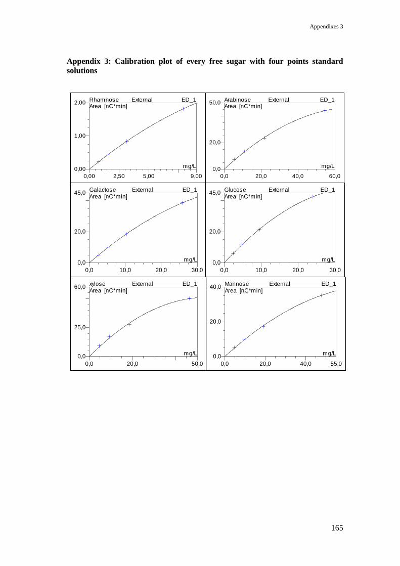
Appendixes 3
165
Appendix 3: Calibration plot of every free sugar with four points standard
solutions
0,00
1,00
2,00
0,00 2,50 5,00 9,00
Rhamnose External ED_1Area [nC*min]
mg/L0,0
20,0
50,0
0,0 20,0 40,0 60,0
Arabinose External ED_1Area [nC*min]
mg/L
0,0
20,0
45,0
0,0 10,0 20,0 30,0
Galactose External ED_1Area [nC*min]
mg/L0,0
20,0
45,0
0,0 10,0 20,0 30,0
Glucose External ED_1Area [nC*min]
mg/L
0,0
25,0
60,0
0,0 20,0 50,0
xylose External ED_1Area [nC*min]
mg/L0,0
20,0
40,0
0,0 20,0 40,0 55,0
Mannose External ED_1Area [nC*min]
mg/L
166
Curriculum vitae
AZIZAH BINTI BAHARUM E-mail Add: [email protected] / [email protected]
PERSONAL DETAILS
Gender: Female
Date/Place of Birth: 23rd
January 1978 / Kuala Terengganu, Terengganu, Malaysia
Age/Status: 34 years old / Married with a daughter and a son
Race/Nationality: Malay / Malaysian
Office Add: PPSKTM, Faculty of Science and Technology, National University of
Malaysia, 43600 Bangi, Selangor, Malaysia
EDUCATION BACKGROUND
2006 – 2012 (11 semesters): Technical University Braunschweig
Ph.D. in chemistry
Full time research at Fraunhofer, Wilhelm-Klauditz-Institut für Holzforchung
2000 – 2002 (5 semesters): National University of Malaysia, Bangi, Selangor
Master of Science (Chemistry), Full time research
Research project: Processing of NR/LLDPE/Twaron composite using a twin screw extruder
1997 – 2000 (6 semesters): National University of Malaysia, Bangi, Selangor
Bachelor of Science, Second class Honours (Upper division)
Field of Study: Chemical Technology, Final year project: Vulcanization of NR/LNR with sulfur
WORKING EXPERIENCES
Dis 2005 – Sept 2006: National University of Malaysia
Lecturer at Faculty of Science and Technology
July – Dis 2005: National University of Malaysia
Tutor at Faculty of Science and Technology
July 2003 – July 2005: Technology University of Malaysia
Lecturer at Military Academy Malaysia
Feb – July 2003: National University of Malaysia
Research assistant at Faculty of Science and Technology
ACHIEVEMENT/PUBLICATION
Silver medal in the UKM Research and Innovation Exhibition 2003
Ishak Ahmad, Norul Azwan Din, Affendi Mohamad, Azizah Abdul Aziz & Ibrahim Abdullah.
2005. Penambahan Gentian Aramid (Twaron) dalam Adunan NR/LLDPE dan ENR/LLDPE
terhadap sifat Mekanik Komposit. Sains Malaysiana 34(1): 57-61
Ishak Ahmad, Azizah Baharum, Mohd Khairil Saat & Ibrahim Abdullah, Kesan Komposisi
Gentian dan Kaedah Pemprosesan ke atas Sifat Mekanik Komposit NR/LLDPE Diperkuat
Twaron, Sains Malaysiana 33(2) 2004: 9-19.
Azizah Abdul Aziz, Ishak Ahmad, Ibrahim Abdullah, The Effect of Filler Loading on the
Mechanical Properties of 60/40 NR/LLDPE blends, 5th
UKM-ITB Proceeding 2002
Azizah Baharum, Ishak Ahmad, Ibrahim Abdullah, Kesan Komposisi NR/LLDPE/Twaron ke atas
Sifat Mekanik dan Dinamik – Prosiding Kolokium FST Pertama 2002
Azizah Baharum, Ishak Ahmad, Ibrahim Abdullah, The Effect of extrusion rate on the
Mechanical Properties of Twaron Reinforced Natural Rubber/ LLDPE Composite, National
Symposium on Polymeric Material 2001 Proceeding.