Information IS 180-2 - ses-shop.ch4097,4098.pdf · PERPA Ticaret Merkezi A Blok Kat 5 No.313 ·...
15
DE STEINEL Vertrieb GmbH Dieselstraße 80-84 · 33442 Herzebrock-Clarholz Tel: +49/5245/448-188 www.steinel.de AT Steinel Austria GmbH Hirschstettner Strasse 19/A/2/2 · A-1220 Wien Tel.: +43/1/2023470 · [email protected] CH PUAG AG Oberebenestrasse 51 · CH-5620 Bremgarten Tel.: +41/56/6488888 · [email protected] GB STEINEL U.K. LTD. 25, Manasty Road · Axis Park · Orton Southgate GB-Peterborough Cambs PE2 6UP Tel.: +44/1733/366-700 · [email protected] IE Socket Tool Company Ltd Unit 714 Northwest Business Park Kilshane Drive Ballycoolin · Dublin 15 Tel.: 00353 1 8809120 · [email protected] FR STEINEL FRANCE SAS ACTICENTRE - CRT 2 Rue des Famards - Bât. M - Lot 3 F-59818 Lesquin Cedex Tél.: +33/3/20 30 34 00 · [email protected] NL Van Spijk B.V. Postbus 2 · 5688 HP OIRSCHOT De Scheper 402 · 5688 HP OIRSCHOT Tel. +31 499 571810 [email protected] · www.vanspijk.nl BE VSA Belgium Hagelberg 29 · B-2440 Geel Tel.: +32/14/256050 [email protected] · www.vsabelgium.be LU Minusines S.A. 8, rue de Hogenberg · L-1022 Luxembourg Tél. : (00 352) 49 58 58 1 · www.minusines.lu ES SAET-94 S.L. C/ Trepadella, n° 10 · Pol. Ind. Castellbisbal Sud E-08755 Castellbisbal (Barcelona) Tel.: +34/93/772 28 49 · [email protected] IT STEINEL Italia S.r.l. Largo Donegani 2 · I-20121 Milano Tel.: +39/02/96457231 [email protected] · www.steinel.it PT F.Fonseca S.A. Rua Joao Francisco do Casal 87/89 Esgueira 3800-266 Aveiro - Portugal Tel. +351 234 303 900 [email protected] · www.ffonseca.com SE KARL H STRÖM AB Verktygsvägen 4 · SE-553 02 Jönköping Tel.: +46 36 550 33 00 · [email protected] · www.khs.se DK Roliba A/S Hvidkærvej 52 · DK-5250 Odense SV Tel.: +45 6593 0357 · www.roliba.dk FI Oy Hedtec Ab Lauttasaarentie 50 · FI-00200 Helsinki Puh.: +358/207 638 000 [email protected] · www.hedtec.fi/valaistus NO Vilan AS Olaf Helsetsvei 8 · N-0694 Oslo Tel.: +47/22725000 [email protected] · www.vilan.no GR PANOS Lingonis + Sons O. E. Aristofanous 8 Str. · GR-10554 Athens Tel.: +30/210/3212021 · [email protected] TR SAOS Teknoloji Elektrik Sanayi ve Ticaret Limited Şirketi Halil Rıfat Paşa mahallesi Yüzerhavuz Sokak PERPA Ticaret Merkezi A Blok Kat 5 No.313 · Şişli / İSTANBUL Tel.: +90 212 220 09 20 [email protected] · www.saosteknoloji.com.tr CZ ELNAS s.r.o. Oblekovice 394 · CZ-67181 Znojmo Tel.: +420/515/220126 [email protected] · www.elnas.cz PL „LŁ“ Spółka z ograniczoną odpowiedzialnością sp.k. Byków, ul. Wrocławska 43 · PL-55-095 Mirków Tel.: +48 71 3980818 [email protected] · www.langelukaszuk.pl HU DINOCOOP Kft Radvány u. 24 · H-1118 Budapest Tel.: +36/1/3193064 · [email protected] LT KVARCAS Neries krantine 32 · LT-48463, Kaunas Tel.: +370/37/408030 · [email protected] EE Fortronic AS Tööstuse tee 10 · EST-61715 Tõrvandi Ülenurme vald, Tartumaa Tel.: +372/7/475208 [email protected] · www.fortronic.ee SI ELEKTRO – PROJEKT PLUS D.O.O. Suha pri Predosljah 12 SLO-4000 Kranj PE GRENC 2 · 4220 Škofja Loka Tel.: 00386-4-2521645 · GSM: 00386-40-856555 [email protected] · www.priporocam.si SK NECO SK, A.S. Ružová ul. 111 · SK-01901 Ilava Tel.: +421/42/4 45 67 10 [email protected] · www.neco.sk RO Steinel Distribution SRL Parc Industrial Metrom RO-500269 Brasov · Str. Carpatilor nr. 60 Tel.: +40(0)268 53 00 00 · www.steinel.ro HR Daljinsko upravljanje d.o.o. Bedricha Smetane 10 · HR-10000 Zagreb t/ 00385 1 388 66 77 [email protected] · www.daljinsko-upravljanje.hr LV Ambergs SIA Brivibas gatve 195-16 · LV-1039 Riga Tel.: 00371 67550740 · www.ambergs.lv BG ТАШЕВ-ГАЛВИНГ ООД Бул. Климент Охридски № 68 1756 София, България Тел.: +359 2 700 45 45 4 [email protected] · www.tashev-galving.com RU Best - Snab ул.1812 года, дом 12 · 121127 Москва · Россия Tel: +7 (495) 280-35-53 [email protected] · www.steinel.su CN STEINEL China Representative Office Shanghai Rm. 25 A · Huadu Mansion No. 838 Zhangyang Road Shanghai 200122 Tel: +86 21 5820 4486 [email protected] · [email protected] · www.steinel.cn 110059087 08/2017_K Technische Änderungen vorbehalten. / Subject to technical modification without notice. IS 180-2 Information DE GB FR NL IT ES PT SE DK FI NO GR TR HU
Transcript of Information IS 180-2 - ses-shop.ch4097,4098.pdf · PERPA Ticaret Merkezi A Blok Kat 5 No.313 ·...
DE STEINEL Vertrieb GmbH Dieselstraße 80-84 · 33442 Herzebrock-Clarholz Tel: +49/5245/448-188 www.steinel.de
AT Steinel Austria GmbH Hirschstettner Strasse 19/A/2/2 · A-1220 Wien Tel.: +43/1/2023470 · [email protected]
CH PUAG AG Oberebenestrasse 51 · CH-5620 Bremgarten Tel.: +41/56/6488888 · [email protected]
GB STEINEL U.K. LTD. 25, Manasty Road · Axis Park · Orton Southgate GB-Peterborough Cambs PE2 6UP Tel.: +44/1733/366-700 · [email protected]
IE Socket Tool Company Ltd Unit 714 Northwest Business Park Kilshane Drive Ballycoolin · Dublin 15 Tel.: 00353 1 8809120 · [email protected]
FR STEINEL FRANCE SAS ACTICENTRE - CRT 2 Rue des Famards - Bât. M - Lot 3 F-59818 Lesquin Cedex Tél.: +33/3/20 30 34 00 · [email protected]
NL Van Spijk B.V. Postbus 2 · 5688 HP OIRSCHOT De Scheper 402 · 5688 HP OIRSCHOT Tel. +31 499 571810 [email protected] · www.vanspijk.nl
BE VSA Belgium Hagelberg 29 · B-2440 Geel Tel.: +32/14/256050 [email protected] · www.vsabelgium.be
LU Minusines S.A. 8, rue de Hogenberg · L-1022 Luxembourg Tél. : (00 352) 49 58 58 1 · www.minusines.lu
ES SAET-94 S.L. C/ Trepadella, n° 10 · Pol. Ind. Castellbisbal Sud E-08755 Castellbisbal (Barcelona) Tel.: +34/93/772 28 49 · [email protected]
IT STEINEL Italia S.r.l. Largo Donegani 2 · I-20121 Milano Tel.: +39/02/96457231 [email protected] · www.steinel.it
PT F.Fonseca S.A. Rua Joao Francisco do Casal 87/89 Esgueira 3800-266 Aveiro - Portugal Tel. +351 234 303 900 [email protected] · www.ffonseca.com
SE KARL H STRÖM AB Verktygsvägen 4 · SE-553 02 Jönköping Tel.: +46 36 550 33 00 · [email protected] · www.khs.se
DK Roliba A/S Hvidkærvej 52 · DK-5250 Odense SV Tel.: +45 6593 0357 · www.roliba.dk
FI Oy Hedtec Ab Lauttasaarentie 50 · FI-00200 Helsinki Puh.: +358/207 638 000 [email protected] · www.hedtec.fi/valaistus
NO Vilan AS Olaf Helsetsvei 8 · N-0694 Oslo Tel.: +47/22725000 [email protected] · www.vilan.no
GR PANOS Lingonis + Sons O. E. Aristofanous 8 Str. · GR-10554 Athens Tel.: +30/210/3212021 · [email protected]
TR SAOS Teknoloji Elektrik Sanayi ve Ticaret Limited Şirketi Halil Rıfat Paşa mahallesi Yüzerhavuz Sokak PERPA Ticaret Merkezi A Blok Kat 5 No.313 · Şişli / İSTANBUL Tel.: +90 212 220 09 20 [email protected] · www.saosteknoloji.com.tr
CZ ELNAS s.r.o. Oblekovice 394 · CZ-67181 Znojmo Tel.: +420/515/220126 [email protected] · www.elnas.cz
PL „LŁ“ Spółka z ograniczoną odpowiedzialnością sp.k. Byków, ul. Wrocławska 43 · PL-55-095 Mirków Tel.: +48 71 3980818 [email protected] · www.langelukaszuk.pl
HU DINOCOOP Kft Radvány u. 24 · H-1118 Budapest Tel.: +36/1/3193064 · [email protected]
LT KVARCAS Neries krantine 32 · LT-48463, Kaunas Tel.: +370/37/408030 · [email protected]
EE Fortronic AS Tööstuse tee 10 · EST-61715 Tõrvandi Ülenurme vald, Tartumaa Tel.: +372/7/475208 [email protected] · www.fortronic.ee
SI ELEKTRO – PROJEKT PLUS D.O.O. Suha pri Predosljah 12 SLO-4000 Kranj PE GRENC 2 · 4220 Škofja Loka Tel.: 00386-4-2521645 · GSM: 00386-40-856555 [email protected] · www.priporocam.si
SK NECO SK, A.S. Ružová ul. 111 · SK-01901 Ilava Tel.: +421/42/4 45 67 10 [email protected] · www.neco.sk
RO Steinel Distribution SRL Parc Industrial Metrom RO-500269 Brasov · Str. Carpatilor nr. 60 Tel.: +40(0)268 53 00 00 · www.steinel.ro
HR Daljinsko upravljanje d.o.o. Bedricha Smetane 10 · HR-10000 Zagreb t/ 00385 1 388 66 77 [email protected] · www.daljinsko-upravljanje.hr
LV Ambergs SIA Brivibas gatve 195-16 · LV-1039 Riga Tel.: 00371 67550740 · www.ambergs.lv
BG ТАШЕВ-ГАЛВИНГ ООД Бул. Климент Охридски № 68 1756 София, България Тел.: +359 2 700 45 45 4 [email protected] · www.tashev-galving.com
RU Best - Snab ул.1812 года, дом 12 · 121127 Москва · Россия Tel: +7 (495) 280-35-53 [email protected] · www.steinel.su
CN STEINEL China Representative Office Shanghai Rm. 25 A · Huadu Mansion No. 838 Zhangyang Road Shanghai 200122 Tel: +86 21 5820 4486 [email protected] · [email protected] · www.steinel.cn
1100
5908
7 08
/201
7_K
Tec
hnis
che
Änd
erun
gen
vo
rbeh
alte
n. /
Sub
ject
to
tec
hnic
al m
od
ifi ca
tion
with
out
no
tice.
IS 180-2
Information
DE
GB
FR
NL
ITES
PT
SE
DK
FI
NO
GR
TR
HU
– 2 – – 3 –
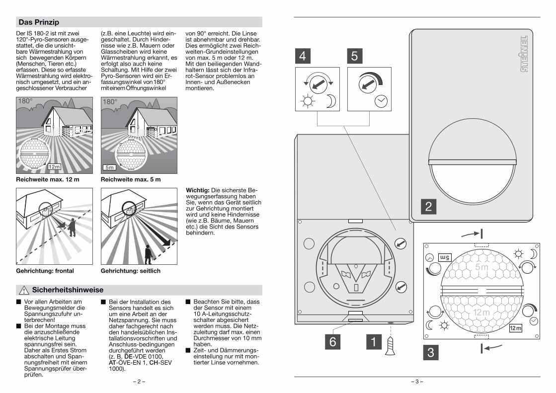
Sicherheitshinweise
W Vor allen Arbeiten am Bewegungsmelder die Spannungszufuhr un-terbrechen!
W Bei der Montage muss die anzuschließende elektrische Leitung spannungsfrei sein. Daher als Erstes Strom abschalten und Span-nungsfreiheit mit einem Spannungsprüfer über-prüfen.
W Bei der Installation des Sensors handelt es sich um eine Arbeit an der Netzspannung. Sie muss daher fachgerecht nach den handelsüblichen Ins-tallationsvorschriften und Anschluss-bedingungen durchgeführt werden (z. B. DE-VDE 0100, AT-ÖVE-EN 1, CH-SEV 1000).
W Beachten Sie bitte, dass der Sensor mit einem 10 A-Leitungsschutz-schalter abgesichert werden muss. Die Netz-zuleitung darf max. einen Durchmesser von 10 mm haben.
W Zeit- und Dämmerungs-einstellung nur mit mon-tierter Linse vornehmen.
Das Prinzip
Der IS 180-2 ist mit zwei 120°-Pyro-Sensoren ausge-stattet, die die unsicht-bare Wärmestrahlung von sich bewegenden Körpern (Menschen, Tieren etc.) erfassen. Diese so erfasste Wärmestrahlung wird elektro-nisch umgesetzt, und ein an-geschlossener Verbraucher
(z.B. eine Leuchte) wird ein-geschaltet. Durch Hinder-nisse wie z.B. Mauern oder Glasscheiben wird keine Wärmestrahlung erkannt, es erfolgt also auch keine Schaltung. Mit Hilfe der zwei Pyro-Sensoren wird ein Er-fassungswinkel von 180° mit einem Öffnungswinkel
von 90° erreicht. Die Linse ist abnehmbar und drehbar. Dies ermöglicht zwei Reich-weiten-Grundeinstellungen von max. 5 m oder 12 m. Mit den beiliegenden Wand-haltern lässt sich der Infra-rot-Sensor problemlos an Innen- und Außenecken montieren.
Wichtig: Die sicherste Be-wegungserfassung haben Sie, wenn das Gerät seitlich zur Gehrichtung montiert wird und keine Hindernisse (wie z.B. Bäume, Mauern etc.) die Sicht des Sensors behindern.
Reichweite max. 12 m Reichweite max. 5 m
Gehrichtung: frontal Gehrichtung: seitlich

– 4 – – 5 –
Der Montageort sollte min-destens 50 cm von einer Leuchte entfernt sein, da deren Wärmestrahlung zu Fehlauslösungen des Sen-sors führen kann. Um die angegebenen Reichweiten von 5/12 m zu erzielen, sollte die Montagehöhe ca. 2 m betragen.
Montageschritte:1. Designblende 2 abzie-hen, 2. Rastnase 6 lösen und untere Gehäusehälfte aufklappen, 3. Bohrlöcher anzeichnen, 4. Löcher bohren, Dübel (Ø 6 mm) setzen, 5. Wand für Ka-beleinführung je nach Bedarf für Aufputz- oder Unterputzzuleitung heraus-brechen.6. Kabel der Netz- und Ver-braucherzuleitung hindurch-führen und anschließen. Bei Kabelzuleitung Aufputz Dichtstopfen verwenden.a) Anschluss der
NetzzuleitungDie Netzzuleitung besteht aus einem 2- bis 3-adrigen Kabel:L = PhaseN = NullleiterPE = SchutzleiterIm Zweifel müssen Sie die Kabel mit einem Span-nungsprüfer identifi zieren; anschließend wieder span-nungsfrei schalten. Phase (L) und Nullleiter (N) werden entsprechend der Klemm-belegung angeschlossen. Der Schutzleiter wird am Erdungskontakt ( ) ange-klemmt. In die Netzzuleitung kann selbstverständlich ein Netz-schalter zum Ein- und Ausschalten montiert sein. Alternativ kann der Sensor manuell für die Dauer der eingestellten Zeit durch einen Öffner-Taster in der Netzzuleitung aktiviert werden.
Hinweis: Zur Wandmonta-ge kann auch der beiliegen-de Inneneck-Wandhalter benutzt werden. Die Kabel können so bequem von oben hinter dem Gerät her und durch die Öffnung der Kabelzuleitung Aufputz hindurchgeführt werden.
Kabelzuleitung Aufputz
NetzzuleitungVerbraucherzuleitung
Kabelzuleitung Aufputz mit Wandhalter
Kabelzuleitung Unterputz
Installation/WandmontageDE Montageanleitung
Sehr geehrter Kunde,
vielen Dank für das Vertrau-en, das Sie uns mit dem Kauf dieses STEINEL-Infrarot-Sensors entgegen-gebracht haben. Sie haben sich für ein hochwertiges Qualitätsprodukt ent-schieden, das mit größter
Sorgfalt produziert, getestet und verpackt wurde.Bitte machen Sie sich vor der Installation mit dieser Montageanleitung vertraut. Denn nur eine sachgerechte Installation und Inbetrieb-nahme gewährleisten einen
langen, zuverlässigen und störungsfreien Betrieb.
Wir wünschen Ihnen viel Freude an Ihrem neuen Infrarot-Sensor.
Gerätebeschreibung
1 Sicherungsschraube
2 Designblende
3 Linse (abnehmbar und drehbar zur Auswahl der Reichweiten-Grundein-stellung von max. 5 m oder 12 m)
4 Dämmerungseinstellung2 – 2000 Lux
5 Zeiteinstellung10 Sek. 15 Min.
6 Rastnase (Gehäuse zur Montage und zum Netz-anschluss aufklappbar)
Abmessungen: (H x B x T) 120 x 76 x 56 mmLeistung: Glühlampen, max. 1000 W bei 230 V AC Leuchtstoffröhre, max. 500 W bei cos = 0,5, induktive Last bei 230 V AC 6 x max. à 58 W, C ≤ 132 µF bei 230 V AC *1)
Netzanschluss: 230 – 240 V, 50 HzErfassungswinkel 180° horizontal, 90° vertikal Reichweite des Sensors: Grundeinstellung 1: max. 5 m Grundeinstellung 2: max. 12 m (Werkseinstellung) + Feinjustierung durch Abdeckschalen 1 – 12 mZeiteinstellung: 10 Sek. – 15 Min. (Werkseinstellung: 10 Sek.)Dämmerungseinstellung: 2 – 2000 Lux (Werkseinstellung: 2000 Lux)Schutzart: IP 54*1) Leuchtstoffl ampen, Energiesparlampen, LED-Leuchten mit elektronischem Vorschaltgerät
(Gesamtkapazität aller angeschlossenen Vorschaltgeräte unter dem angegebenen Wert).
Technische Daten
DE
– 6 – – 7 –
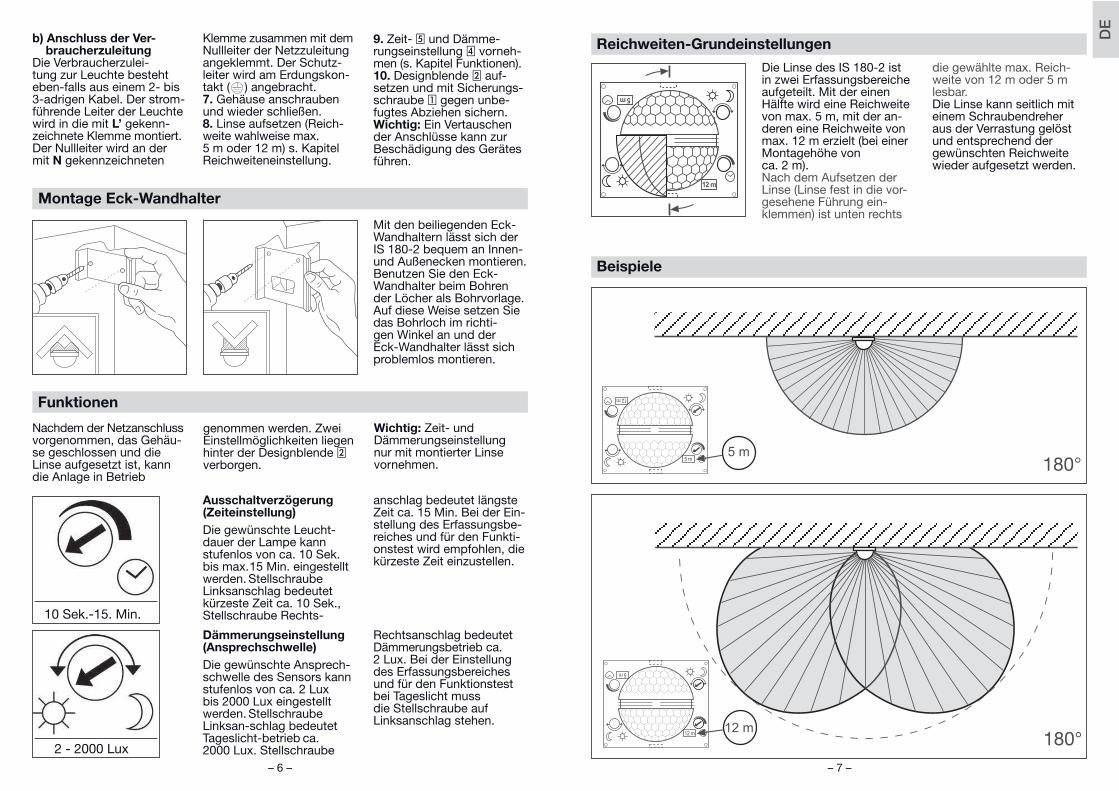
Reichweiten-Grundeinstellungen
Die Linse des IS 180-2 ist in zwei Erfassungsbereiche aufgeteilt. Mit der einen Hälfte wird eine Reichweite von max. 5 m, mit der an-deren eine Reichweite von max. 12 m erzielt (bei einer Montagehöhe von ca. 2 m). Nach dem Aufsetzen der Linse (Linse fest in die vor-gesehene Führung ein-klemmen) ist unten rechts
die gewählte max. Reich-weite von 12 m oder 5 m lesbar. Die Linse kann seitlich mit einem Schraubendreher aus der Verrastung gelöst und entsprechend der gewünschten Reichweite wieder aufgesetzt werden.
Beispiele
Funktionen
Nachdem der Netzanschluss vorgenommen, das Gehäu-se geschlossen und die Linse aufgesetzt ist, kann die Anlage in Betrieb
genommen werden. Zwei Einstellmöglichkeiten liegen hinter der Designblende 2 verborgen.
Wichtig: Zeit- und Dämmerungseinstellung nur mit montierter Linse vornehmen.
Ausschaltverzögerung(Zeiteinstellung)
Die gewünschte Leucht-dauer der Lampe kann stufenlos von ca. 10 Sek. bis max. 15 Min. eingestellt werden. Stellschraube Linksanschlag bedeutet kürzeste Zeit ca. 10 Sek., Stellschraube Rechts-
anschlag bedeutet längste Zeit ca. 15 Min. Bei der Ein-stellung des Erfassungsbe-reiches und für den Funkti-onstest wird empfohlen, die kürzeste Zeit einzustellen.
Dämmerungseinstellung(Ansprechschwelle)
Die gewünschte Ansprech-schwelle des Sensors kann stufenlos von ca. 2 Lux bis 2000 Lux eingestellt werden. Stellschraube Linksan-schlag bedeutet Tageslicht-betrieb ca. 2000 Lux. Stellschraube
Rechtsanschlag bedeutet Dämmerungsbetrieb ca. 2 Lux. Bei der Einstellung des Erfassungsbereiches und für den Funktionstest bei Tageslicht muss die Stellschraube auf Linksanschlag stehen.
10 Sek.-15. Min.
2 - 2000 Lux
Mit den beiliegenden Eck-Wandhaltern lässt sich der IS 180-2 bequem an Innen- und Außenecken montieren. Benutzen Sie den Eck-Wandhalter beim Bohren der Löcher als Bohrvorlage. Auf diese Weise setzen Sie das Bohrloch im richti-gen Winkel an und der Eck-Wandhalter lässt sich problemlos montieren.
Montage Eck-Wandhalter
b) Anschluss der Ver-braucherzuleitung
Die Verbraucherzulei-tung zur Leuchte besteht eben-falls aus einem 2- bis 3-adrigen Kabel. Der strom-führende Leiter der Leuchte wird in die mit L’ gekenn-zeichnete Klemme montiert. Der Nullleiter wird an der mit N gekennzeichneten
Klemme zusammen mit dem Nullleiter der Netzzuleitung angeklemmt. Der Schutz-leiter wird am Erdungskon-takt ( ) angebracht.7. Gehäuse anschrauben und wieder schließen.8. Linse aufsetzen (Reich-weite wahlweise max. 5 m oder 12 m) s. Kapitel Reichweiteneinstellung.
9. Zeit- 5 und Dämme-rungseinstellung 4 vorneh-men (s. Kapitel Funktionen).10. Designblende 2 auf-setzen und mit Sicherungs-schraube 1 gegen unbe-fugtes Abziehen sichern.Wichtig: Ein Vertauschen der Anschlüsse kann zur Beschädigung des Gerätes führen.
DE
– 8 – – 9 –
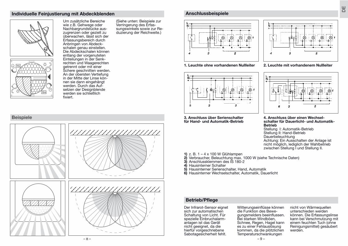
Betrieb/Pfl ege
Der Infrarot-Sensor eignet sich zur automatischen Schaltung von Licht. Für spezielle Einbruchalarm-anlagen ist das Gerät nicht geeignet, da die hierfür vorgeschriebene Sabotagesicherheit fehlt.
Witterungseinfl üsse können die Funktion des Bewe-gungsmelders beeinfl ussen. Bei starken Windböen, Schnee, Regen, Hagel kann es zu einer Fehlauslösung kommen, da die plötzlichen Temperaturschwankungen
nicht von Wärmequellen unterschieden werden können. Die Erfassungslinse kann bei Verschmutzung mit einem feuchten Tuch (ohne Reinigungsmittel) gesäubert werden.
Anschlussbeispiele
1. Leuchte ohne vorhandenen Nullleiter 2. Leuchte mit vorhandenem Nullleiter
3. Anschluss über Serienschalter für Hand- und Automatik-Betrieb
4. Anschluss über einen Wechsel-schalter für Dauerlicht- und Automatik-BetriebStellung I: Automatik-BetriebStellung II: Hand-Betrieb DauerbeleuchtungAchtung: Ein Ausschalten der Anlage ist nicht möglich, lediglich der Wahlbetrieb zwischen Stellung I und Stellung II.
1) z. B. 1 – 4 x 100 W Glühlampen2) Verbraucher, Beleuchtung max. 1000 W (siehe Technische Daten)3) Anschlussklemmen des IS 180-24) Hausinterner Schalter5) Hausinterner Serienschalter, Hand, Automatik6) Hausinterner Wechselschalter, Automatik, Dauerlicht
Individuelle Feinjustierung mit Abdeckblenden
Beispiele
Um zusätzliche Bereiche wie z.B. Gehwege oder Nachbargrundstücke aus-zugrenzen oder gezielt zu überwachen, lässt sich der Erfassungsbereich durch Anbringen von Abdeck-schalen genau einstellen.Die Abdeckschalen können entlang der vorgenuteten Einteilungen in der Senk-rechten und Waagerechten getrennt oder mit einer Schere geschnitten werden. An der obersten Vertiefung in der Mitte der Linse kön-nen sie dann eingehängt werden. Durch das Auf-setzen der Designblende werden sie schließlich fi xiert.
(Siehe unten: Beispiele zur Verringerung des Erfas-sungswinkels sowie zur Re-duzierung der Reichweite.)
DE
– 10 – – 11 –
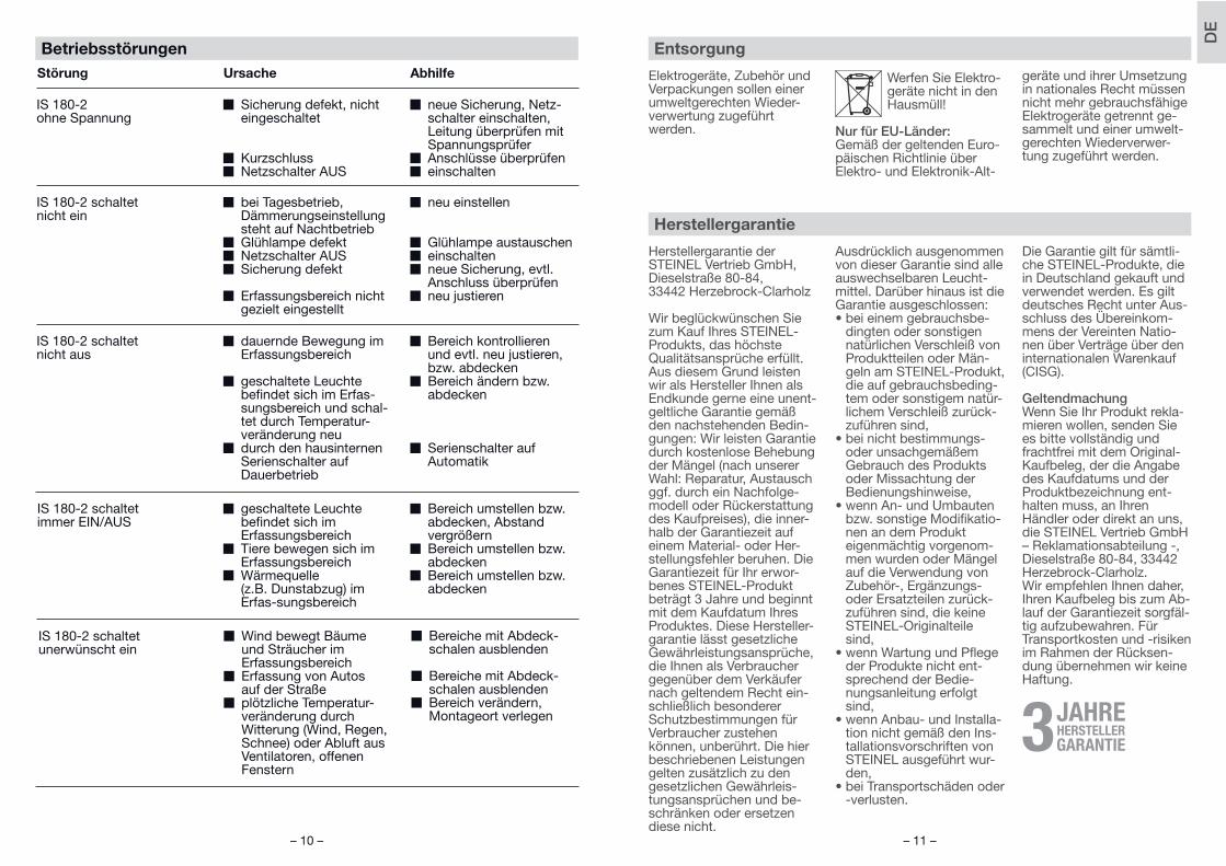
Betriebsstörungen
Störung Ursache Abhilfe
IS 180-2 ohne Spannung
W Sicherung defekt, nicht eingeschaltet
W KurzschlussW Netzschalter AUS
W neue Sicherung, Netz-schalter einschalten, Leitung überprüfen mit Spannungsprüfer
W Anschlüsse überprüfenW einschalten
IS 180-2 schaltet nicht ein
W bei Tagesbetrieb, Dämmerungseinstellung steht auf Nachtbetrieb
W Glühlampe defektW Netzschalter AUSW Sicherung defekt
W Erfassungsbereich nicht gezielt eingestellt
W neu einstellen
W Glühlampe austauschenW einschaltenW neue Sicherung, evtl.
Anschluss überprüfenW neu justieren
IS 180-2 schaltet nicht aus
W dauernde Bewegung im Erfassungsbereich
W geschaltete Leuchte befi ndet sich im Erfas-sungsbereich und schal-tet durch Temperatur-veränderung neu
W durch den hausinternen Serienschalter auf Dauerbetrieb
W Bereich kontrollieren und evtl. neu justieren, bzw. abdecken
W Bereich ändern bzw. abdecken
W Serienschalter auf Automatik
IS 180-2 schaltet immer EIN/AUS
W geschaltete Leuchte befi ndet sich im Erfassungsbereich
W Tiere bewegen sich im Erfassungsbereich
W Wärmequelle (z.B. Dunstabzug) im Erfas-sungsbereich
W Bereich umstellen bzw. abdecken, Abstand vergrößern
W Bereich umstellen bzw. abdecken
W Bereich umstellen bzw. abdecken
IS 180-2 schaltet unerwünscht ein
W Wind bewegt Bäume und Sträucher im Erfassungsbereich
W Erfassung von Autos auf der Straße
W plötzliche Temperatur-veränderung durch Witterung (Wind, Regen, Schnee) oder Abluft aus Ventilatoren, offenen Fenstern
W Bereiche mit Abdeck-schalen ausblenden
W Bereiche mit Abdeck-schalen ausblenden
W Bereich verändern, Montageort verlegen
Herstellergarantie der STEINEL Vertrieb GmbH,Dieselstraße 80-84, 33442 Herzebrock-Clarholz
Wir beglückwünschen Sie zum Kauf Ihres STEINEL-Produkts, das höchste Qualitätsansprüche erfüllt. Aus diesem Grund leisten wir als Hersteller Ihnen als Endkunde gerne eine unent-geltliche Garantie gemäß den nachstehenden Bedin-gungen: Wir leisten Garantie durch kostenlose Behebung der Mängel (nach unserer Wahl: Reparatur, Austausch ggf. durch ein Nachfolge-modell oder Rückerstattung des Kaufpreises), die inner-halb der Garantiezeit auf einem Material- oder Her-stellungsfehler beruhen. Die Garantiezeit für Ihr erwor-benes STEINEL-Produkt beträgt 3 Jahre und beginnt mit dem Kaufdatum Ihres Produktes. Diese Hersteller-garantie lässt gesetzliche Gewährleistungsansprüche, die Ihnen als Verbraucher gegenüber dem Verkäufer nach geltendem Recht ein-schließlich besonderer Schutzbestimmungen für Verbraucher zustehen können, unberührt. Die hier beschriebenen Leistungen gelten zusätzlich zu den gesetzlichen Gewährleis-tungsansprüchen und be-schränken oder ersetzen diese nicht.
Ausdrücklich ausgenommen von dieser Garantie sind alle auswechselbaren Leucht-mittel. Darüber hinaus ist die Garantie ausgeschlossen:• bei einem gebrauchsbe-
dingten oder sonstigen natürlichen Verschleiß von Produktteilen oder Män-geln am STEINEL-Produkt, die auf gebrauchsbeding-tem oder sonstigem natür-lichem Verschleiß zurück-zuführen sind,
• bei nicht bestimmungs- oder unsachgemäßem Gebrauch des Produkts oder Missachtung der Bedienungshinweise,
• wenn An- und Umbauten bzw. sonstige Modifikatio-nen an dem Produkt eigenmächtig vorgenom-men wurden oder Mängel auf die Verwendung von Zubehör-, Ergänzungs- oder Ersatzteilen zurück-zuführen sind, die keine STEINEL-Originalteile sind,
• wenn Wartung und Pflege der Produkte nicht ent-sprechend der Bedie-nungsanleitung erfolgt sind,
• wenn Anbau- und Installa-tion nicht gemäß den Ins-tallationsvorschriften von STEINEL ausgeführt wur-den,
• bei Transportschäden oder -verlusten.
Die Garantie gilt für sämtli-che STEINEL-Produkte, die in Deutschland gekauft und verwendet werden. Es gilt deutsches Recht unter Aus-schluss des Übereinkom-mens der Vereinten Natio-nen über Verträge über den internationalen Warenkauf (CISG).
GeltendmachungWenn Sie Ihr Produkt rekla-mieren wollen, senden Sie es bitte vollständig und frachtfrei mit dem Original-Kaufbeleg, der die Angabe des Kaufdatums und der Produktbezeichnung ent-halten muss, an Ihren Händler oder direkt an uns, die STEINEL Vertrieb GmbH – Reklamationsabteilung -, Dieselstraße 80-84, 33442 Herzebrock-Clarholz.Wir empfehlen Ihnen daher, Ihren Kaufbeleg bis zum Ab-lauf der Garantiezeit sorgfäl-tig aufzubewahren. Für Transportkosten und -risiken im Rahmen der Rücksen-dung übernehmen wir keine Haftung.
Herstellergarantie
HERSTELLER3
Elektrogeräte, Zubehör und Verpackungen sollen einer umweltgerechten Wieder-verwertung zugeführt werden.
Werfen Sie Elektro-geräte nicht in den Hausmüll!
Nur für EU-Länder:Gemäß der geltenden Euro-päischen Richtlinie über Elektro- und Elektronik-Alt-
geräte und ihrer Umsetzung in nationales Recht müssen nicht mehr gebrauchsfähige Elektrogeräte getrennt ge-sammelt und einer umwelt-gerechten Wiederverwer-tung zugeführt werden.
Entsorgung
DE
– 12 – – 13 –
Safety warnings
W Disconnect the power before attempting any work on the motion detector.
W The electrical connec-tion lead must be dead during installation. Therefore, switch off the power supply fi rst and check that the circuit is disconnected using a voltage tester.
W Installation of the sensor involves work on the mains power supply. This work must therefore be carried out profes-sionally in accordance with the applicable wiring regulations and supply conditions.
W Please note that the sen-sor must be protected by a 10 A circuit breaker. The mains supply lead must be no greater than 10 mm in diameter.
W Only carry out time and light threshold settings with the lens fi tted.
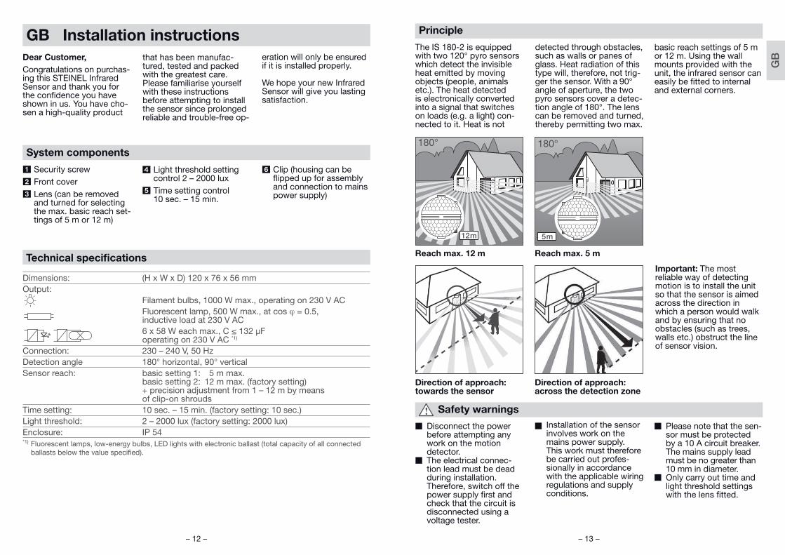
Principle
The IS 180-2 is equipped with two 120° pyro sensors which detect the invisible heat emitted by moving objects (people, animals etc.). The heat detected is electronically converted into a signal that switches on loads (e.g. a light) con-nected to it. Heat is not
detected through obstacles, such as walls or panes of glass. Heat radiation of this type will, therefore, not trig-ger the sensor. With a 90° angle of aperture, the two pyro sensors cover a detec-tion angle of 180°. The lens can be removed and turned, thereby permitting two max.
basic reach settings of 5 m or 12 m. Using the wall mounts provided with the unit, the infrared sensor can easily be fi tted to internal and external corners.
Important: The most reliable way of detecting motion is to install the unit so that the sensor is aimed across the direction in which a person would walk and by ensuring that no obstacles (such as trees, walls etc.) obstruct the line of sensor vision.
Reach max. 12 m Reach max. 5 m
Direction of approach: towards the sensor
Direction of approach: across the detection zone
GB Installation instructions
Dear Customer,
Congratulations on purchas-ing this STEINEL Infrared Sensor and thank you for the confi dence you have shown in us. You have cho-sen a high-quality product
that has been manufac-tured, tested and packed with the greatest care.Please familiarise yourself with these instructions before attempting to install the sensor since prolonged reliable and trouble-free op-
eration will only be ensured if it is installed properly.
We hope your new Infrared Sensor will give you lasting satisfaction.
System components
1 Security screw
2 Front cover
3 Lens (can be removed and turned for selecting the max. basic reach set-tings of 5 m or 12 m)
4 Light threshold setting control 2 – 2000 lux
5 Time setting control10 sec. – 15 min.
6 Clip (housing can be fl ipped up for assembly and connection to mains power supply)
Dimensions: (H x W x D) 120 x 76 x 56 mmOutput: Filament bulbs, 1000 W max., operating on 230 V AC Fluorescent lamp, 500 W max., at cos = 0.5, inductive load at 230 V AC 6 x 58 W each max., C ≤ 132 µF operating on 230 V AC *1)
Connection: 230 – 240 V, 50 HzDetection angle 180° horizontal, 90° vertical Sensor reach: basic setting 1: 5 m max. basic setting 2: 12 m max. (factory setting) + precision adjustment from 1 – 12 m by means of clip-on shroudsTime setting: 10 sec. – 15 min. (factory setting: 10 sec.)Light threshold: 2 – 2000 lux (factory setting: 2000 lux)Enclosure: IP 54*1) Fluorescent lamps, low-energy bulbs, LED lights with electronic ballast (total capacity of all connected
ballasts below the value specifi ed).
Technical specifi cations
GB
– 14 – – 15 –
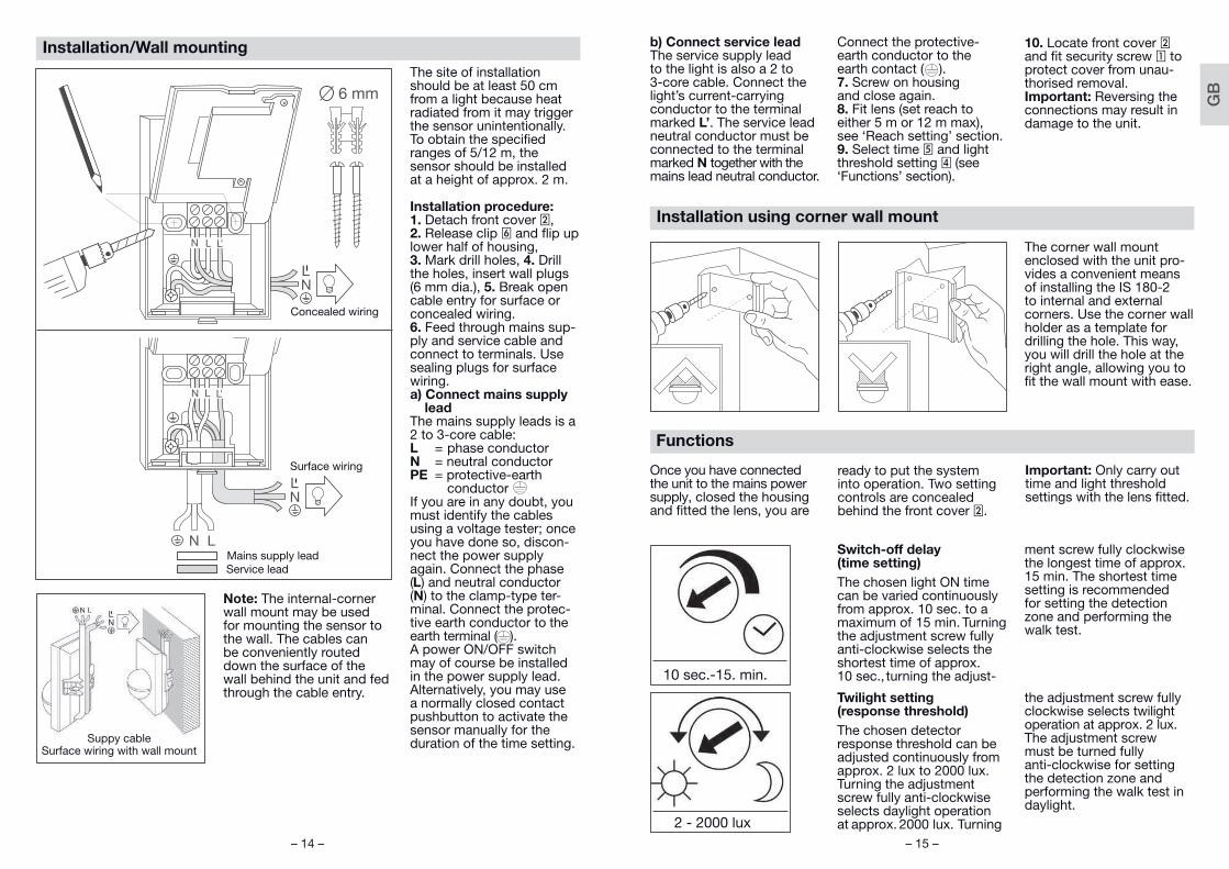
Functions
Once you have connected the unit to the mains power supply, closed the housing and fi tted the lens, you are
ready to put the system into operation. Two setting controls are concealed behind the front cover 2.
Important: Only carry out time and light threshold settings with the lens fi tted.
Switch-off delay(time setting)
The chosen light ON time can be varied continuously from approx. 10 sec. to a maximum of 15 min. Turning the adjustment screw fully anti-clockwise selects the shortest time of approx. 10 sec., turning the adjust-
ment screw fully clockwise the longest time of approx. 15 min. The shortest time setting is recommended for setting the detection zone and performing the walk test.
Twilight setting(response threshold)
The chosen detector response threshold can be adjusted continuously from approx. 2 lux to 2000 lux. Turning the adjustment screw fully anti-clockwise selects daylight operation at approx. 2000 lux. Turning
the adjustment screw fully clockwise selects twilight operation at approx. 2 lux. The adjustment screw must be turned fully anti-clockwise for setting the detection zone and performing the walk test in daylight.
10 sec.-15. min.
2 - 2000 lux
The corner wall mount enclosed with the unit pro-vides a convenient means of installing the IS 180-2 to internal and external corners. Use the corner wall holder as a template for drilling the hole. This way, you will drill the hole at the right angle, allowing you to fi t the wall mount with ease.
Installation using corner wall mount
b) Connect service leadThe service supply lead to the light is also a 2 to 3-core cable. Connect the light’s current-carrying conductor to the terminal marked L’. The service lead neutral conductor must be connected to the terminal marked N together with the mains lead neutral conductor.
Connect the protective-earth conductor to the earth contact ( ).7. Screw on housingand close again.8. Fit lens (set reach to either 5 m or 12 m max), see ‘Reach setting’ section.9. Select time 5 and light threshold setting 4 (see ‘Functions’ section).
10. Locate front cover 2 and fi t security screw 1 to protect cover from unau-thorised removal.Important: Reversing the connections may result in damage to the unit.
The site of installation should be at least 50 cm from a light because heat radiated from it may trigger the sensor unintentionally. To obtain the specifi ed ranges of 5/12 m, the sensor should be installed at a height of approx. 2 m.
Installation procedure:1. Detach front cover 2, 2. Release clip 6 and fl ip up lower half of housing, 3. Mark drill holes, 4. Drill the holes, insert wall plugs (6 mm dia.), 5. Break open cable entry for surface or concealed wiring.6. Feed through mains sup-ply and service cable and connect to terminals. Use sealing plugs for surface wiring.a) Connect mains supply
leadThe mains supply leads is a 2 to 3-core cable:L = phase conductorN = neutral conductorPE = protective-earth conductorIf you are in any doubt, you must identify the cables using a voltage tester; once you have done so, discon-nect the power supply again. Connect the phase (L) and neutral conductor (N) to the clamp-type ter-minal. Connect the protec-tive earth conductor to the earth terminal ( ). A power ON/OFF switch may of course be installed in the power supply lead. Alternatively, you may use a normally closed contact pushbutton to activate the sensor manually for the duration of the time setting.
Note: The internal-corner wall mount may be used for mounting the sensor to the wall. The cables can be conveniently routed down the surface of the wall behind the unit and fed through the cable entry.
Surface wiring
Mains supply leadService lead
Suppy cable Surface wiring with wall mount
Concealed wiring
Installation/Wall mounting
GB

– 16 – – 17 –
Precision adjustment using shrouds
Examples
Shrouds may be used to defi ne the detection zone exactly as you require in order, for example, to blank out or specifi cally targetpaths or neighbouring premises.The shrouds can be divided or cut with a pair of scissors along the vertical and hori-zontal grooves. They can be clipped into the top channel around the centre of the lens. They are fi xed in place by fi tting the frontcover.
(See below: Examples showing how to reduce the angle of detection and shorten the reach).
Basic reach settings
The lens of the IS 180-2 is divided into two detection zones. One half covers a max. reach of 5 m, the other half a max. reach of 12 m (when installed at a height of approx. 2 m). After fi tting the lens (press lens fi rmly into the channel provided) you will see the max. reach setting (12 m or 5 m) at the bottom right.
Using a screwdriver, the lens can be unclipped from the groove at the side and re-positioned for the reach you require.
Examples
GB
– 18 – – 19 –
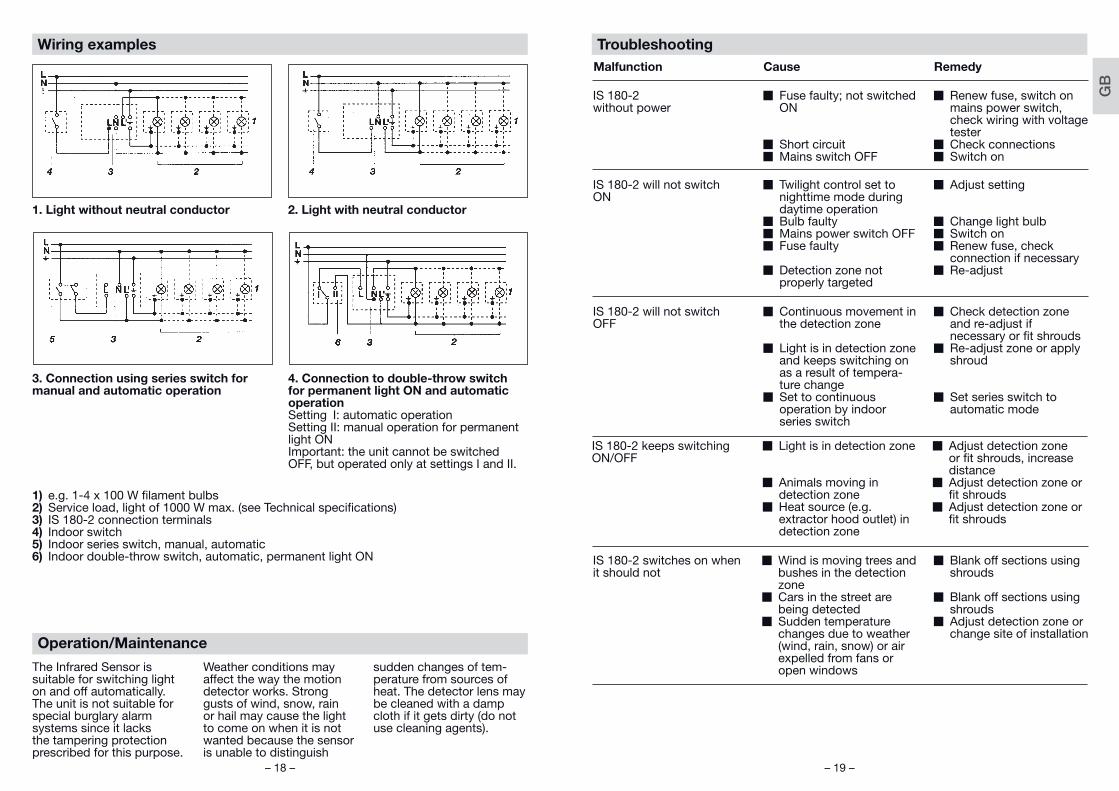
Troubleshooting
Malfunction Cause Remedy
IS 180-2 without power
W Fuse faulty; not switched ON
W Short circuitW Mains switch OFF
W Renew fuse, switch on mains power switch, check wiring with voltage tester
W Check connectionsW Switch on
IS 180-2 will not switchON
W Twilight control set to nighttime mode during daytime operation
W Bulb faultyW Mains power switch OFFW Fuse faulty
W Detection zone not properly targeted
W Adjust setting
W Change light bulbW Switch onW Renew fuse, check
connection if necessaryW Re-adjust
IS 180-2 will not switchOFF
W Continuous movement in the detection zone
W Light is in detection zone and keeps switching on as a result of tempera-ture change
W Set to continuous operation by indoor series switch
W Check detection zoneand re-adjust if necessary or fi t shrouds
W Re-adjust zone or apply shroud
W Set series switch to automatic mode
IS 180-2 keeps switchingON/OFF
W Light is in detection zone
W Animals moving in detection zone
W Heat source (e.g. extractor hood outlet) in detection zone
W Adjust detection zone or fi t shrouds, increase distance
W Adjust detection zone or fi t shrouds
W Adjust detection zone or fi t shrouds
IS 180-2 switches on when it should not
W Wind is moving trees and bushes in the detection zone
W Cars in the street arebeing detected
W Sudden temperature changes due to weather (wind, rain, snow) or air expelled from fans or open windows
W Blank off sections using shrouds
W Blank off sections using shrouds
W Adjust detection zone or change site of installation
Operation/Maintenance
The Infrared Sensor is suitable for switching light on and off automatically. The unit is not suitable for special burglary alarm systems since it lacks the tampering protection prescribed for this purpose.
Weather conditions may affect the way the motion detector works. Strong gusts of wind, snow, rain or hail may cause the light to come on when it is not wanted because the sensor is unable to distinguish
sudden changes of tem-perature from sources of heat. The detector lens may be cleaned with a damp cloth if it gets dirty (do not use cleaning agents).
Wiring examples
1. Light without neutral conductor 2. Light with neutral conductor
3. Connection using series switch for manual and automatic operation
4. Connection to double-throw switch for permanent light ON and automatic operationSetting I: automatic operationSetting II: manual operation for permanent light ONImportant: the unit cannot be switched OFF, but operated only at settings I and II.
1) e.g. 1-4 x 100 W fi lament bulbs2) Service load, light of 1000 W max. (see Technical specifi cations)3) IS 180-2 connection terminals4) Indoor switch5) Indoor series switch, manual, automatic6) Indoor double-throw switch, automatic, permanent light ON
GB

– 20 – – 21 –
FR Instructions de montage
Cher client,Nous vous remercions de la confi ance que vous avez té-moignée à STEINEL en ache-tant ce détecteur infrarouge. Vous avez choisi un article de très grande qualité, fabriqué, testé et conditionné avec le plus grand soin.
Avant de l’installer, veuillez lire attentivement ces instructions de montage. En effet, seules une installation et une mise en service correctement effectuées garantissent dura-blement un fonctionnement impeccable et fi able.
Nous souhaitons que votre nouveau détecteur infrarouge vous apporte entière satis-faction.
Description de l’appareil
1 Vis de blocage
2 Cache design
3 Lentille (amovible et pivo-tante pour choisir le réglage de base de portée de 5 ou 12 m max.)
4 Réglage de crépuscularité 2 – 2 000 lux
5 Temporisation 10 s – 15 min
6 Cran (boîtier ouvrant pour le montage et le branchement au secteur)
Dimensions : (H x L x P) 120 x 76 x 56 mmPuissance : Lampes à incandescence, 1000 W max. pour 230 V CA Tube fl uorescent, 500 W max. pour cos = 0,5, charge inductive pour 230 V CA 6 x 58 W max. chacune, C ≤ 132 µF pour 230 V CA *1)
Alimentation électrique : 230 – 240 V, 50 HzAngle de détection : 180° horizontalement, 90° verticalement Portée du détecteur : Réglage de base 1 : max. 5 m Réglage de base 2 : max. 12 m (réglage d’usine) + réglage de précision par caches enfi chables 1 -12 mTemporisation : 10 s – 15 min (réglage d’usine : 10 s)Réglage de crépuscularité : 2 – 2 000 lux (réglage d’usine : 2 000 lux)Indice de protection : IP 54*1) Tubes fl uorescents, lampes à économie d’énergie, lampes LED avec ballast électronique
(capacité totale de tous les ballasts connectés inférieure à la valeur indiquée).
Caractéristiques techniques
This STEINEL product has been manufactured with ut-most care, tested for proper operation and safety and then subjected to random sample inspection. Steinel guarantees that it is in per-fect condition and proper working order. The warranty period is 36 months and starts on the date of sale to the consum-er. We will remedy defects caused by material flaws or manufacturing faults. The warranty will be met by re-pair or replacement of de-fective parts at our own dis-
cretion. The warranty shall not cover damage to wear parts, damage or defects caused by improper treat-ment or maintenance.Further consequential dam-age to other objects shall be excluded. Claims under the warranty will only be accepted if the unit is sent fully assembled and well-packed with a brief descrip-tion of the fault, a receipt or invoice (date of purchase and dealer's stamp) to the appropriate Service Centre.
Service:Our Customer Service Department will repair faults not covered by warranty or after the warranty period. Please send the product well-packed to your nearest service station.
Functional Warranty
FR
– 22 – – 23 –
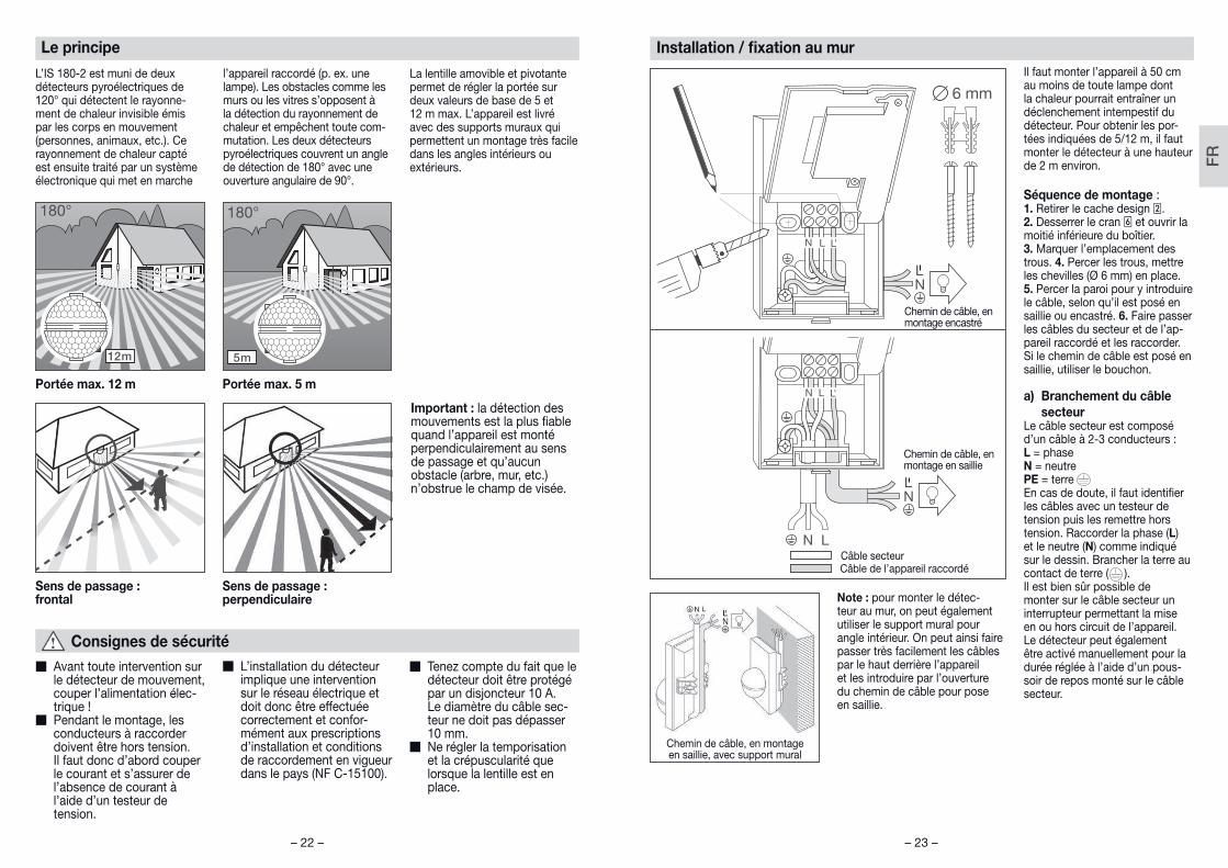
Il faut monter l’appareil à 50 cm au moins de toute lampe dont la chaleur pourrait entraîner un déclenchement intempestif du détecteur. Pour obtenir les por-tées indiquées de 5/12 m, il faut monter le détecteur à une hauteur de 2 m environ.
Séquence de montage :1. Retirer le cache design 2. 2. Desserrer le cran 6 et ouvrir la moitié inférieure du boîtier. 3. Marquer l’emplacement des trous. 4. Percer les trous, mettre les chevilles (Ø 6 mm) en place. 5. Percer la paroi pour y introduire le câble, selon qu’il est posé en saillie ou encastré. 6. Faire passer les câbles du secteur et de l’ap-pareil raccordé et les raccorder. Si le chemin de câble est posé en saillie, utiliser le bouchon.
a) Branchement du câble
secteurLe câble secteur est composé d’un câble à 2-3 conducteurs :L = phaseN = neutrePE = terreEn cas de doute, il faut identifi er les câbles avec un testeur de tension puis les remettre hors tension. Raccorder la phase (L) et le neutre (N) comme indiqué sur le dessin. Brancher la terre au contact de terre ( ). Il est bien sûr possible de monter sur le câble secteur un interrupteur permettant la mise en ou hors circuit de l’appareil. Le détecteur peut également être activé manuellement pour la durée réglée à l’aide d’un pous-soir de repos monté sur le câble secteur.
Note : pour monter le détec-teur au mur, on peut également utiliser le support mural pour angle intérieur. On peut ainsi faire passer très facilement les câbles par le haut derrière l’appareil et les introduire par l’ouverture du chemin de câble pour pose en saillie.
Chemin de câble, en montage en saillie
Câble secteurCâble de l’appareil raccordé
Chemin de câble, en montage en saillie, avec support mural
Chemin de câble, en montage encastré
Installation / fi xation au mur
Consignes de sécurité
W Avant toute intervention sur le détecteur de mouvement, couper l’alimentation élec-trique !
W Pendant le montage, les conducteurs à raccorder doivent être hors tension. Il faut donc d’abord couper le courant et s’assurer de l’absence de courant à l’aide d’un testeur de tension.
W L’installation du détecteur implique une intervention sur le réseau électrique et doit donc être effectuée correctement et confor-mément aux prescriptions d’installation et conditions de raccordement en vigueur dans le pays (NF C-15100).
W Tenez compte du fait que le détecteur doit être protégé par un disjoncteur 10 A. Le diamètre du câble sec-teur ne doit pas dépasser 10 mm.
W Ne régler la temporisation et la crépuscularité que lorsque la lentille est en place.
Le principe
L’IS 180-2 est muni de deux détecteurs pyroélectriques de 120° qui détectent le rayonne-ment de chaleur invisible émis par les corps en mouvement (personnes, animaux, etc.). Ce rayonnement de chaleur capté est ensuite traité par un système électronique qui met en marche
l’appareil raccordé (p. ex. une lampe). Les obstacles comme les murs ou les vitres s’opposent à la détection du rayonnement de chaleur et empêchent toute com-mutation. Les deux détecteurs pyroélectriques couvrent un angle de détection de 180° avec une ouverture angulaire de 90°.
La lentille amovible et pivotante permet de régler la portée sur deux valeurs de base de 5 et 12 m max. L’appareil est livré avec des supports muraux qui permettent un montage très facile dans les angles intérieurs ou extérieurs.
Important : la détection des mouvements est la plus fi able quand l’appareil est monté perpendiculairement au sens de passage et qu’aucun obstacle (arbre, mur, etc.) n’obstrue le champ de visée.
Portée max. 12 m Portée max. 5 m
Sens de passage : frontal
Sens de passage : perpendiculaire
FR
– 24 – – 25 –
Fonctions
Après avoir branché le détec-teur au secteur, fermé le boîtier et mis la lentille en place, vous pouvez mettre l’installation en service.
En retirant le cache design 2, on accède à deux possibilités de réglage.
Important : ne régler la tempo-risation et la crépuscularité que lorsque la lentille est en place.
Temporisation de l’extinction(Minuterie)La durée d’éclairage souhaitée est réglable en continu d’environ 10 s à 15 min maxi. La temporisa-tion est à son minimum (env. 10 s) quand la vis de réglage est en butée à gauche, à son maximum (env. 15 min) quand la vis est en
butée à droite. Lors du réglage de la zone de détection et du test de fonctionnement, nous conseillons de régler la temporisation minimum.
Réglage de crépuscularité(Seuil de réaction)Le seuil de réaction du détecteur est réglable en continu d’env. 2 à 2 000 lux. Lorsque la vis de réglage est en butée à gauche, l’appareil est en fonctionnement diurne, soit env. 2 000 lux. Lorsque la vis de réglage est en
butée à droite, l’appareil est en fonctionnement crépusculaire, soit env. 2 lux. Lors du réglage de la zone de détection et du test de fonctionnement en plein jour, la vis de réglage doit être en butée à gauche.
10 s - 15 min
2 - 2 000 lux
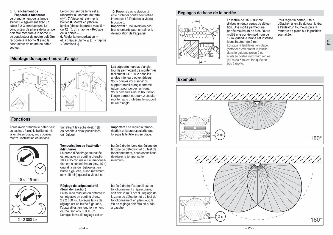
Les supports muraux d’angle fournis permettent de monter très facilement l’IS 180-2 dans les angles intérieurs ou extérieurs. Vous pouvez vous servir du support mural d’angle comme gabarit pour percer les trous. Vous percerez ainsi le trou selon l’angle correct et pourrez ensuite monter sans problème le support mural d’angle.
Montage du support mural d’angle
b) Branchement de l’appareil à raccorder
Le branchement de la lampe s’effectue également avec un câble à 2-3 conducteurs. Le conducteur de phase de la lampe doit être raccordé à la borne L’. Le conducteur de neutre doit être raccordé à la borne N avec le conducteur de neutre du câble secteur.
Le conducteur de terre est à raccorder au contact de terre ( ). 7. Visser et refermer le boîtier. 8. Mettre en place la lentille (choisir la portée maxi 5 m ou 12 m), cf. chapitre « Réglage de la portée ».9. Régler la temporisation 5 et la crépuscularité 4 (cf. chapitre « Fonctions »).
10. Poser le cache design 2 et le protéger contre tout retrait intempestif à l’aide de la vis de blocage 1.Important : une inversion des branchements peut entraîner la détérioration de l’appareil.
Réglages de base de la portée
La lentille de l’IS 180-2 est divisée en deux zones de détec-tion. Une moitié permet une portée maximum de 5 m, l’autre moitié une portée maximum de 12 m (quand la lampe est installée à une hauteur de 2 m). Lorsque la lentille est en place (enfoncer fermement la lentille dans le guidage prévu à cet effet), la portée maximum réglée (12 m ou 5 m) est indiquée en bas à droite.
Pour régler la portée, il faut détacher la lentille du cran latéral à l’aide d’un tournevis puis la remettre en place sur la position souhaitée.
Exemples
FR
– 26 – – 27 –
Utilisation / entretien
Le détecteur infrarouge est indi-qué pour la commutation automa-tique de l’éclairage. Il n’est tou-tefois pas prévu pour les alarmes spéciales anti-intrusion car il n’est pas protégé en conséquence contre le vandalisme. Les condi-
tions atmosphériques peuvent infl uencer le fonctionnement du détecteur de mouvement. Les rafales de vent, la neige, la pluie et la grêle peuvent entraîner un déclenchement intempestif car le détecteur ne peut pas distinguer
les brusques variations de tempé-rature des sources de chaleur. Si la lentille se salit, on la nettoiera avec un chiffon humide (ne pas utiliser de détergent).
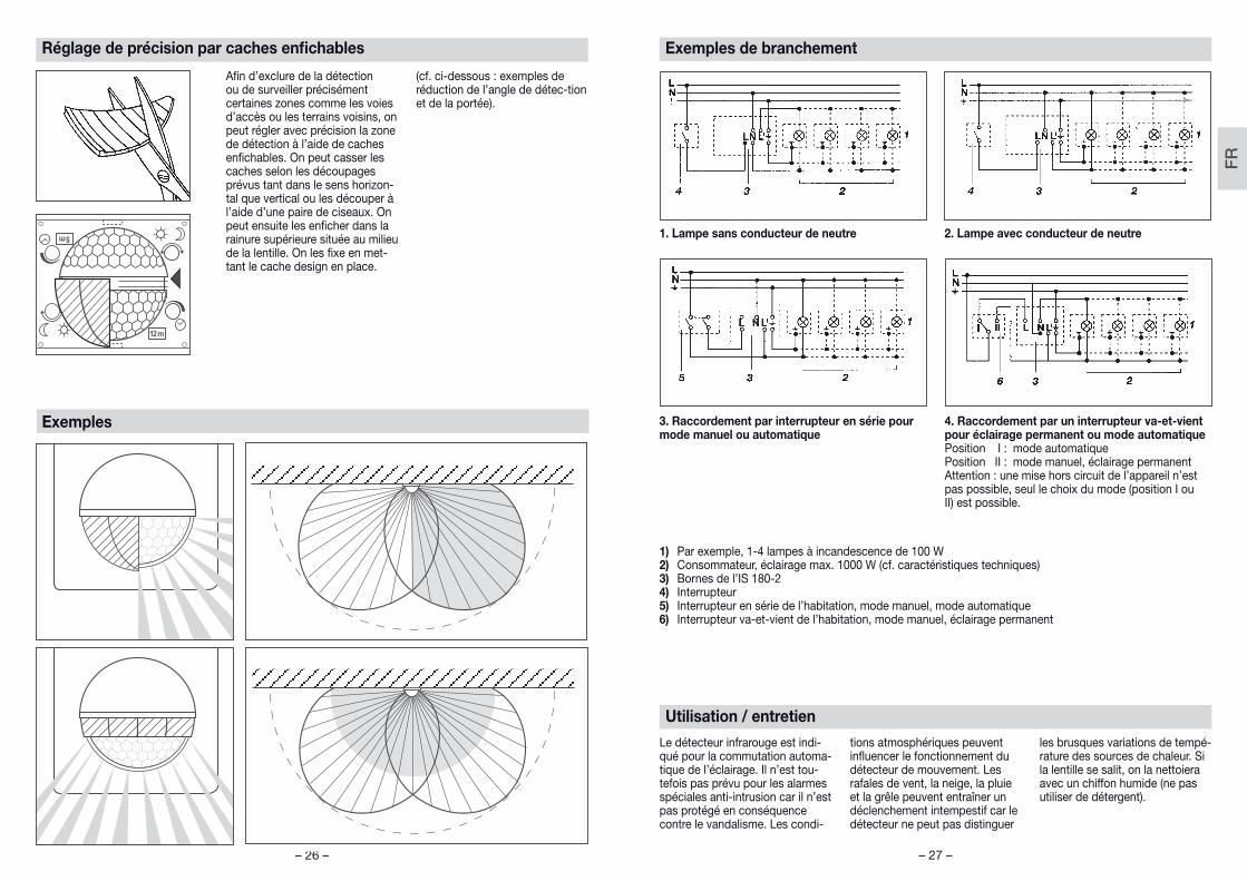
Exemples de branchement
1. Lampe sans conducteur de neutre 2. Lampe avec conducteur de neutre
3. Raccordement par interrupteur en série pour mode manuel ou automatique
4. Raccordement par un interrupteur va-et-vient pour éclairage permanent ou mode automatiquePosition I : mode automatiquePosition II : mode manuel, éclairage permanentAttention : une mise hors circuit de l’appareil n’est pas possible, seul le choix du mode (position I ou II) est possible.
1) Par exemple, 1 -4 lampes à incandescence de 100 W2) Consommateur, éclairage max. 1000 W (cf. caractéristiques techniques)3) Bornes de l’IS 180-24) Interrupteur5) Interrupteur en série de l’habitation, mode manuel, mode automatique6) Interrupteur va-et-vient de l’habitation, mode manuel, éclairage permanent
Réglage de précision par caches enfi chables
Exemples
Afi n d’exclure de la détection ou de surveiller précisément certaines zones comme les voies d’accès ou les terrains voisins, on peut régler avec précision la zone de détection à l’aide de caches enfi chables. On peut casser les caches selon les découpages prévus tant dans le sens horizon-tal que vertical ou les découper à l’aide d’une paire de ciseaux. On peut ensuite les enfi cher dans la rainure supérieure située au milieu de la lentille. On les fi xe en met-tant le cache design en place.
(cf. ci-dessous : exemples de réduction de l’angle de détec-tion et de la portée).
FR
– 28 – – 29 –
Dysfonctionnement
Problème Cause Remède
L’IS 180-2 n’est pas sous tension
W Fusible défectueux, appareil hors circuit, câble coupé
W Court-circuitW Interrupteur en position
ARRÊT
W Changer le fusible défec-tueux, mettre l’interrupteur en circuit, vérifi er le câble à l’aide d’un testeur de tension
W Vérifi er le branchementW Mettre en circuit
L’IS 180-2 ne s’allume pas W Pendant la journée, le réglage de crépuscularité est en position nocturne
W Ampoule défectueuseW Interrupteur en position
ARRÊTW Fusible défectueux
W Réglage incorrect de la zone de détection
W Régler à nouveau
W Changer l’ampouleW Mettre en circuit
W Changer le fusible, éventuellement vérifi er le branchement
W Régler à nouveau
L’IS 180-2 ne s’éteint pas W Mouvement continu dans la zone de détection
W La lampe branchée se trouve dans la zone de détection et se rallume à cause des variations de température
W Mode éclairage permanent commandé au niveau d’un interrupteur en parallèle
W Contrôler la zone de détection, éventuellement la régler à nouveau ou la masquer
W Modifi er la zone ou la masquer
W Mettre l’interrupteur en mode automatique
L’IS 180-2 s’allume et s’éteint continuellement
W La lampe branchée se trouve dans la zone de détection
W Des animaux se déplacent dans la zone de détection
W Source de chaleur (p. ex. conduit d’évacuation) dans la zone de détection
W Modifi er la zone ou la masquer, augmenter la distance
W Modifi er la zone ou la masquer
W Modifi er la zone ou la masquer
L’IS 180-2 s’allume de façon intempestive
W Le vent agite des arbres et des arbustes dans la zone de détection
W Détection de voitures passant sur la chaussée
W Variations subites de température dues aux intempéries (vent, pluie, neige) ou à des courants d’air provenant de ventila-teurs ou de fenêtres ouvertes
W Masquer les zones avec les caches
W Masquer les zones avec les caches
W Modifi er la zone, monter l’appareil à un autre endroit
Ce produit STEINEL a été fabri-qué avec le plus grand soin. Son fonctionnement et sa sécu-rité ont été contrôlés suivant des procédures fiables et il a été soumis à un contrôle final par sondage. STEINEL garantit un état et un fonctionnement irréprochables. La durée de garantie est de 36 mois et débute au jour de la vente au consommateur. Nous remédions aux défauts prove-nant d'un vice de matière ou de construction. La garantie sera assurée à notre discrétion par réparation ou échange des pièces défectueuses. La garan-tie ne s'applique ni aux pièces d'usure, ni aux dommages et défauts dus à une utilisation ou maintenance incorrecte.
Les dommages consécutifs causés à d’autres objets sont exclus de la garantie. La garan-tie ne s'applique que si l'appa-reil non démonté est retourné à la station de service après-vente la plus proche, dans un emballage adéquat, accompa-gné d'une brève description du défaut et d'un ticket de caisse ou d’une facture portant la date d'achat et le cachet du vendeur.
Service après-vente :Le service après-vente de notre usine effectue également les ré-parations non couvertes par la garantie ou survenant après l'expiration de celle-ci. Veuillez envoyer le produit correctement emballé à la station de service après-vente la plus proche.
Garantie de fonctionnement
FR