Integration Issues of Information Engineering Based I-CASE ...
24
University of Münster, Institute of Business Informatics Grevener Straße 91, D-48159 Münster, Germany, Tel. (0251) 83-9750, Fax (0251) 83-9754 September 1994 Working Papers of the Institute of Business Informatics Editors: Prof. Dr. J. Becker, Prof. Dr. H. L. Grob, Prof. Dr. K. Kurbel, Prof. Dr. U. Müller-Funk, Prof. Dr. R. Unland, Prof. Dr. G. Vossen Working Paper No. 33 - Extended version of paper presented at the Fourth International Conference on Information Systems Development, Bled, Slovenia, September 20-22, 1994 - Integration Issues of Information Engineering Based I-CASE Tools Karl Kurbel, Thomas Schnieder
Transcript of Integration Issues of Information Engineering Based I-CASE ...
University of Münster, Institute of Business Informatics
Grevener Straße 91, D-48159 Münster, Germany, Tel. (0251) 83-9750, Fax (0251) 83-9754
September 1994
Working Papers of the Institute of Business Informatics
Editors: Prof. Dr. J. Becker, Prof. Dr. H. L. Grob, Prof. Dr. K. Kurbel,
Prof. Dr. U. Müller-Funk, Prof. Dr. R. Unland, Prof. Dr. G. Vossen
Working Paper No. 33
- Extended version of paper presented at the Fourth International Conference on Information
Systems Development, Bled, Slovenia, September 20-22, 1994 -
Integration Issues of InformationEngineering Based I-CASE Tools
Karl Kurbel, Thomas Schnieder
- 2 -
Contents
1 The "I" of I-CASE 3
1.1 Missing Integration in Software Development 3
1.2 Information Engineering and I-CASE 5
2 Integration in Life-cycle CASE 6
2.1 Horizontal Integration 6
2.2 Vertical Integration 7
2.3 Interpersonal Integration 7
3 Integration Aspects of ADW 8
3.1 Tools of ADW 8
3.2 Horizontal Integration 10
3.3 Vertical Integration 11
3.4 Interpersonal Integration 13
4 Integration Aspects of IEF 14
4.1 Tools of IEF 14
4.2 Horizontal Integration 15
4.3 Vertical Integration 17
4.4 Interpersonal Integration 18
5 Comparison and Conclusions 19
References 20
Abstract
Problems and requirements regarding integration of methods and tools across phases of the
software-development life cycle are discussed. Information engineering (IE) methodology and
I-CASE (integrated CASE) tools supporting IE claim to have an integrated view across major
stages of enterprise-wide information-system development: information strategy planning,
business area analysis, system design, and construction. In the main part of this paper, two
comprehensive I-CASE tools, ADW (Application Development Workbench) and IEF (Infor-
mation Engineering Facility), are analyzed and compared with regard to integration issues.
- 3 -
1 The "I" of I-CASE
1.1 Missing Integration in Software Development
The so-called "software crisis", for the first time addressed in 1968, seems to have continued
until today. Many of the problems of software development are still present: Complexity of
large systems is still not sufficiently mastered. Software contains errors and is unreliable. De-
velopment takes longer and costs more than expected. Maintenance is awkward, time-consum-
ing, and expensive. New information systems (IS) cannot be developed on demand because of
the application backlog, etc.
One of the achievements of the emerging discipline of software engineering was gradual transi-
tion from intuitive to more systematic procedures. In particular, management of the software-
development process became an issue, leading to generic process models (software life-cycle
models). Such models were proposed and further refined by many authors. The best-known
process model is probably the "waterfall model" originally introduced by Royce1) and later
propagated by Boehm2).
The basic structure of the waterfall model, and of other models derived from it, is a linear se-
quence of phases. In principle, each phase is executed once. Although many extensions, modi-
fications, and counter-proposals allowing for minor loops or even major development cycles
have been proposed, the basic linear structure of phases is still found in most process models
employed in practice.
From this, it is not surprising that early computerized tools assisting software developers were
also designed according to phases of the process. Drawbacks of the waterfall model − e.g. lack
of feedback from later to earlier phases, loss of information between phases due to breaks re-
garding language and representation − were thus transferred to supporting tools as well. Many
CASE (computer-aided software engineering) tools give only limited support − just for one
phase or for a few phases of the development cycle, or just for one view of the problem (e.g.
for process modeling, but not for data modeling)3). When isolated tools have to be applied for
different phases, or for different aspects of the problem, work can become rather cumbersome.
Consider, for example, a development project where one tool for Structured Analysis is used
to define processes and data flows, and another tool is used to develop an entity-relationship
1) Cf. Royce (1970).2) Cf. Boehm (1981).3) Cf. Nomina (1993).
- 4 -
model, but there is no connection between these tools. In this case, developers will have to en-
ter the same data twice − and maybe even a third time, namely when the data structures finally
will be specified for the target database management system. Problems resulting from this
redundancy are well-known. Tool integration therefore is an important issue. Lack of inte-
gration is a major criticism regarding CASE tools4) because it is detrimental to acceptance of
CASE by the users5).
Integrated tools do not only enhance development productivity but also help to avoid unneces-
sary inconsistencies among different representations of the same things. Various approaches
aiming at tool integration − in particular integration of tools from different vendors − have
been proposed6). The best-known example is probably IBM's Repository Manager. Its un-
derlying idea was a common information model for all tools. Tools should use this model to
represent their data, to store them in the repository, and also be able to read data created by
other tools from the repository. IBM's failure with this concept after ten years of development
effort shows very clearly that this solution is a difficult one7).
Integration of tools requires integration of methods first8). Different methods applied
throughout the development cycle have to match. This means that (a) if different methods are
applied for different views of the problem, results have to be compatible in the sense that they
can be joined in further problem solving, and (b) that results achieved in one phase can be used
as input for methods used in the next phase.
Another aspect regarding lack of integration is related to the fact that real-world information
systems are rarely stand-alone systems. Instead, they are part of enterprise-wide information
management and have to match with other information systems. Software engineering, how-
ever, takes a rather limited view: It looks at development of just one information system at a
time, but it does not take into account explicitly that many interlocking IS are needed to solve
business problems. Integration of information systems as a development goal has long been ne-
glected by software engineering.
4) Cf. Stobart et al. (1993), p. 84.5) Cf. Zarrella (1990), p. 208.6) Cf. e.g. Dineur (1990), Venable (1990), Wybolt (1991).7) Cf. e.g. Polilli (1992), Bucken (1992).8) Cf. Robinson (1991), p. 507.
- 5 -
1.2 Information Engineering and I-CASE
A more comprehensive view of business information processing underlies the information engi-
neering methodology introduced by James Martin. According to Martin, information engi-
neering (IE) is "the application of an interlocking set of formal techniques for the planning,
analysis, design, and construction of information systems on an enterprise-wide basis or across
a major sector of the enterprise"9). Information engineering proceeds in a top-down manner,
starting with overall strategic planning and continuing with analysis of major sectors of the
enterprise, design of individual information systems within this framework, and finally con-
struction of these systems.
Information processing is treated on four levels of abstraction, corresponding to major devel-
opment stages. In IE publications, these levels are often depicted as a pyramid.
• Information strategy planning (ISP) is concerned with strategic goals and critical success
factors of the enterprise, and how information technology can help to achieve these goals.
A high-level overview is created of the enterprise, its functions, data, and information
needs. It is represented in various models. Major business areas are identified.
• In business area analysis (BAA), those areas are examined in detail. In particular, the fun-
damental data and the fundamental processes needed to run a business area as well as their
interrelations are analyzed. Data models and functional models of ISP are refined.
• System design (SD) is concerned with individual information systems identified in BAA.
Procedural logic, user interfaces, reports, and database schemata are specified here. Each
IS may be regarded as a separate SD project.
• In construction, specifications from SD are used to create executable programs, data
definitions, and database accesses. According to IE philosophy, this should happen auto-
matically.
The four stages may be regarded as a generic macro process model, but this model differs from
other process models in that it is not a linear list of phases but a tree (for example, several de-
sign projects may have to be conducted within one business area).
9) Cf. Martin (1989), p. 1.
- 6 -
The major concern of information engineering is integration across stages and tool support.
This means that not only techniques employed in the four stages have to match but also that
there have to be tools supporting these techniques, and that these tools have to be integrated.
Information engineering is closely related to tool support. In another definition of IE, Martin
indicates this property more directly, describing IE as "an interlocking set of automated tech-
niques in which enterprise models, data models, and process models are built up in a compre-
hensive knowledge base and are used to create and maintain data processing systems"10).
Integration regarding tools means, among others, that the entire development cycle has to be
supported, i.e. all stages from ISP to construction. Information engineering tools thus have to
be I-CASE (integrated CASE) tools. Two well-known tool sets supporting the comprehensive
and rather sophisticated IE philosophy are: ADW (Application Development Workbench) by
KnowledgeWare and IEF (Information Engineering Facility) by Texas Instruments Information
Engineering.
In this paper, both tools will be analyzed and compared with regard to integration issues.
Chapter 2 describes those issues in more detail. Afterwards, ADW will be examined in chapter
3, and IEF in chapter 4. Some conclusions are given in chapter 5.
2 Integration in Life-cycle CASE
Considering the number of papers and software products addressing "integration", this term
has become something like a buzzword. Integration may simply mean, for example, that user
interfaces of different tools are alike, that data can be interchanged between tools for one
phase, or that more than one phase of the life cycle is covered somehow11). In this paper, we
discuss integration from two points of view. One is the tool view, i.e. horizontal and vertical
integration among tools. The other one is the interpersonal view, related to cooperative devel-
opment.
2.1 Horizontal Integration
Horizontal integration refers to tools that are employed within one IE stage. As will be illus-
trated below, there is quite a number of tools available for each stage. They deal with different
10) Cf. Martin (1989), p. 1.11) Cf. Zarrella (1990).
- 7 -
aspects of the problem to be solved (e.g. process decomposition, data flows), or they show the
same things in different views. For example, entities appear in entity-relationship diagrams, in
data flow diagrams, in association matrices, etc.
Horizontal integration means that tools can easily interchange their results and that modifi-
cations or new results established by one tool are immediately available for other tools. This is
particularly important with regard to information interchange between two complementary
views of IS development, the data view and the activities view (functions, processes, proce-
dures). Whereas data and activities have been treated separately in the past, it is a major con-
cern of information engineering that data modeling and process modeling should go hand in
hand. This can only work, however, if the tools supporting either view are truly integrated.
2.2 Vertical Integration
Vertical integration means integration across information engineering stages, or, in general,
across life-cycle phases. Results established with tools of one stage should be available to tools
of other stages in a natural way. In particular, results should be represented not only as docu-
mentation but also in a format that they can be processed automatically by other tools.
Two specific aspects of vertical integration are forward integration and reverse integration.
Forward integration capability calls for features permitting model objects to be specified on a
high abstraction level first and to be expanded and enriched by additional details later. Reverse
integration capability means that changes made in the representation format of a later stage
will be adopted in the models and representation formats used in earlier stages. As an example,
consider relational database design during the SD stage. If relations representing additional en-
tity types are introduced here, those entity types should also be represented automatically in
the ER models of business area analysis.
2.3 Interpersonal Integration
When several people form a development team, intermediate results are produced at different
places, e.g. on different workstations connected in a local-area network, if not stand-alone.
Distributed development is typical for most real-world IS projects. In this case, distributed re-
sults have to be coordinated in a systematic manner. The most straightforward solution to this
problem (and the most ambitious one at the same time) is a central repository all distributed
workplaces are connected to and all tools store their results in, but it is difficult to realize.
IBM's failure with this approach has already been mentioned. Central repositories, however,
- 8 -
also have other drawbacks12); for example, they suffer from severe performance problems.
Distributed repositories may reduce some of the problems, but ensuring consistency among in-
termediate results established at different places is even harder. Techniques to maintain consis-
tency in team work were proposed by Garbajosa et al.13) and Robinson14), for example. Such
techniques are state of the art in the field of CSCW (computer-supported cooperative work),
but in I-CASE tools advanced CSCW concepts have not been implemented yet.
3 Integration Aspects of ADW
ADW (Application Development Workbench) is a large tool set for information engineering
distributed by KnowledgeWare Inc. According to KnowledgeWare ADW has over 5,000 cus-
tomers worldwide. ADW is the successor of IEW (Information Engineering Workbench). It
runs on PCs under the OS/2 operating system. Target environments are primarily IBM main-
frames under MVS. Since 1992, OS/2-based PCs with Presentation Manager (PM) interface
are also supported. Very recently, in version 2.7, MS-Windows has been added to the list of
target operating systems. This report and evaluation is based on experience with ADW, version
1.6.04, for OS/2 PM both as development and target environment.
3.1 Tools of ADW
All information collected and produced during IE stages is stored in an encyclopedia. Objects
of an encyclopedia are, for example, business functions, processes, organizational units, entity
types, etc. Developers describe those objects by so-called details associated with them, and
specify interrelations between objects.
For this purpose, a set of tools is available. ADW tools are grouped, according to IE stages,
into four subsets called workstations15):
• Planning Workstation
• Analysis Workstation
• Design Workstation
• Construction Workstation.
12) Cf. Kramer (1991), p. 501.13) Cf. Garbojosa et al. (1990).14) Cf. Robinson (1991).15) Cf. KnowledgeWare (1994).
- 9 -
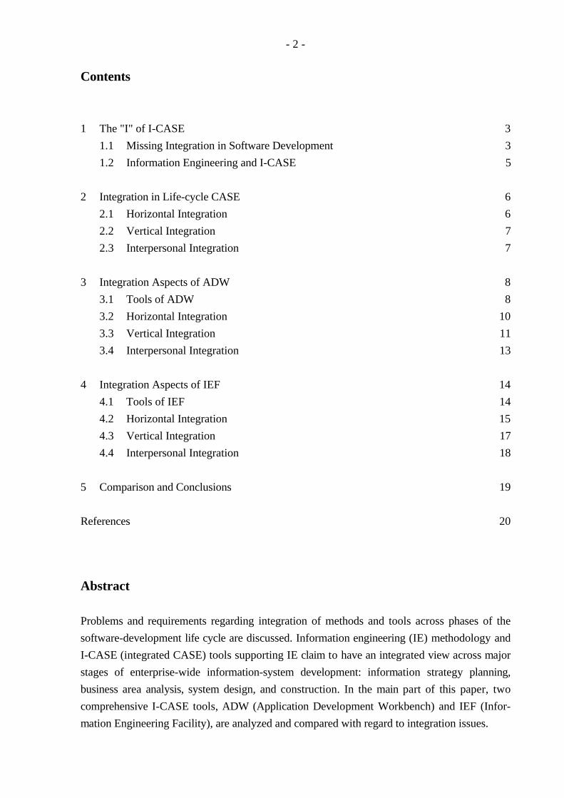
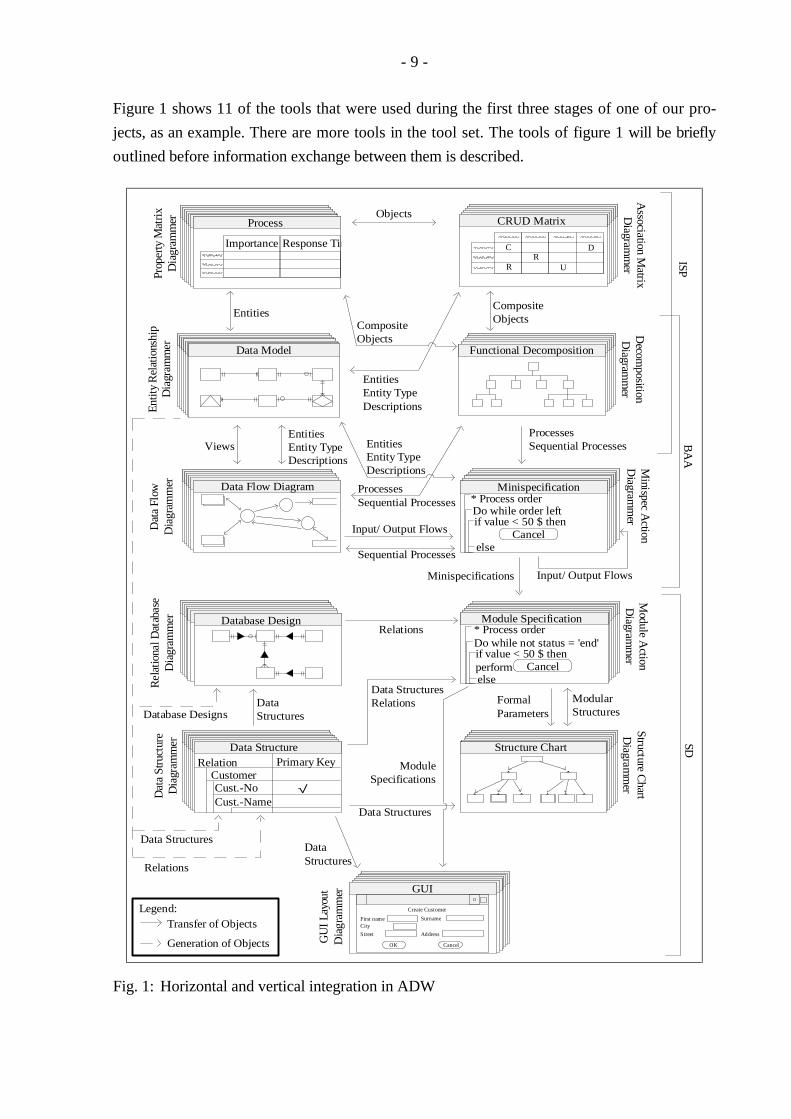
Figure 1 shows 11 of the tools that were used during the first three stages of one of our pro-
jects, as an example. There are more tools in the tool set. The tools of figure 1 will be briefly
outlined before information exchange between them is described.
Importance Response TimeImportance Response Time
Ziele
Minispecification
Database Design
Data Model
* Process order
Structure ChartData StructureRelation Primary Key
CustomerCust.-No
GUI
Create Customer
First name Surname
Street Address
CancelOK
Cancelif value < 50 $ thenDo while order left
Objects
Pro
perty
Mat
rix
Dia
gram
mer
EntitiesCompositeObjects
Association M
atrix D
iagramm
erD
ecomposition
Diagram
mer
ProcessesSequential ProcessesViews
Ent
ity R
elat
ions
hip
Dia
gram
mer
Input/ Output Flows
Minispec A
ction D
iagramm
erDat
a F
low
D
iagr
amm
erR
ela
tiona
l Dat
aba
se
Dia
gram
mer
Relations
Module A
ction D
iagramm
er
FormalParameters
ModularStructures
Module Specifications
Dat
a S
truc
ture
D
iagr
amm
er
Structure C
hart D
iagram
mer
GU
I Lay
out
Dia
gra
mm
er
Database Designs
Relations
EntitiesEntity TypeDescriptions
Data StructuresRelations
ISP
SD
BA
A
Importance Response Time
Process
Data Flow Diagram
Functional Decomposition
R
C
R
U
R
CR
U
D
CRUD Matrix
Importance Response Time
EntitiesEntity TypeDescriptions
Module Specification
Sequential Processes
* Process order
else
Cancelif value < 50 $ thenperform
Do while not status = 'end'
else
DataStructures
Data StructuresDataStructures
Cust.-Name
City
Generation of Objects
Transfer of ObjectsLegend:
Minispecifications
Data Structures
EntitiesEntity TypeDescriptions
CompositeObjects
ProcessesSequential Processes
Input/ Output Flows
√
Fig. 1: Horizontal and vertical integration in ADW
- 10 -
The Association Matrix Diagrammer is used to specify relations between different types of en-
cyclopedia objects (e.g. which entities are read or written by which processes). Hierarchical
relations are described and plotted with the help of the Decomposition Diagrammer (e.g. proc-
ess hierarchies, organizational structures). The Property Matrix Diagrammer is applied to
specify details of objects (e.g. entity descriptions). The Entity Relationship Diagrammer sup-
ports data modeling. Connections between data and processes are described by data flow dia-
grams created by the Data Flow Diagrammer. Coarse procedural logic of elementary proc-
esses may be outlined within the Minispec Action Diagrammer and later refined by means of
the Module Action Diagrammer.
3.2 Horizontal Integration
ADW's encyclopedia is a central encyclopedia with respect to the tool view, but it is not a cen-
tral one regarding interpersonal cooperation (see chapter 3.4 below). As to the former view,
"central" means that all pieces of information, no matter which tool they were created with, are
stored just once. All tools have access to the encyclopedia. When they read information from
the encyclopedia, it is transformed into a tool-specific representation format (usually a graph-
ical one) and displayed to the user. When they write information, it is represented within the
encyclopedia in a standard format that can be interpreted by other tools. In this way, con-
sistency among tools is no problem.
Information exchange between tools comprises not only object definitions but also relations be-
tween encyclopedia objects. For example, hierarchical relations among organizational units,
specified by the Decomposition Diagrammer, are also available for the Association Matrix Dia-
grammer; the latter one creates the relationship "organizational unit coordinates organizational
unit" from information about the hierarchy. Vice versa, if a new association is introduced in a
matrix, it will be considered by the Decomposition Diagrammer, too.
An advantage of integrated tools is that the developer may choose the most appropriate tool
for a certain task himself, if the task can be attacked by more than one tool. For example, de-
tails of objects can either be entered directly, by using a specific editor, or with the help of the
Property Matrix Diagrammer. Another example is definition of data flows. The Data Flow Dia-
grammer provides a formal language to describe data flows, but there is a more user-friendly
way to achieve the same result, by means of the Entity Relationship Diagrammer. When a view
of the data flow is specified there, ADW will derive the formal description automatically,
without bothering the user further.
- 11 -
Horizontal integration includes context-sensitive transition from one tool to another. This
means that a tool may be called from within another one, and that the current context of the
first tool will be considered by the second one. If an object has been selected, for example, and
a second tool is called afterwards, the latter one will focus on the selected object and display
information concerning that particular object and its surroundings. For example, when a proc-
ess of a data flow diagram is selected, within the Data Flow Diagrammer, and the Minispec
Action Diagrammer is then called, the procedural description of just that process will be dis-
played.
Furthermore, consistency among different models is supported by context-sensitive transition
from one tool to another, because some information can be derived automatically. Since it is
not necessary to enter it by hand, sources of error are reduced. For example, when the devel-
oper calls the Minispec Action Diagrammer from the Data Flow Diagrammer in order to de-
scribe process logic, input and output data of the process will be derived automatically from
data flow descriptions and displayed within the Minispec Action Diagrammer. In this way,
information from one model (data flow model) is available in another model (process model).
The developer may use it in the description of process logic.
3.3 Vertical Integration
Vertical tool integration across stages is less complete than horizontal integration. In principle,
models and diagrams of earlier stages are available in later stages, but there are several restric-
tions and drawbacks.
Decomposition diagrams (e.g. functional hierarchies), data models, associations, etc. from ISP
can be adopted and further processed by Analysis Workstation tools without any problems. As
to forward integration, however, a distinction has to be made between hierarchical objects and
data. Decomposition diagrams may be further refined by additional levels. For example, busi-
ness functions can be split up into more detailed functions; those functions can be described by
processes which can be further refined by other processes and finally by so-called "elementary
processes".
Refining the ISP data model, however, is less satisfactory. For this purpose, features for clus-
tering entities and relationships would be necessary16), but they are not available in ADW. In-
stead, coarse entities and relationships may be substituted by more detailed ones. This means,
16) Cf. e.g. Teorey (1989), Rauh (1992), Jaeschke (to appear).
- 12 -
however, that the ISP model providing a high-level overview is destroyed. Furthermore, en-
tries of the new data model are on different abstraction levels now. Some parts of the overall
model are elaborated in detail (i.e. parts where business area analysis have been conducted),
whereas other parts are still on a level of coarse description. There is no way of distinguishing
detailed information from high-level one.
Components of the data model defined in ISP and BAA can be processed directly in the design
stage where the relational model is generated from the conceptual ER model. However, the
relational model is just a so-called "first-cut" model. Since ADW's derivation rules are rather
stereotype, the first-cut model needs thorough revision. Generating the relational model from
the ER model could be improved significantly if up-to-date research results were imple-
mented17) For example, if information about functional dependencies were attached to the ER
model during analysis and used by the translator, the resulting relational model would be more
adequate than the uncouth first-cut model.
When changes of the ER model are made, a new relational model (at least a partial model) has
to be generated. Before that, however, all elements of the relational model affected by the
modification must be deleted manually − an error-prone and time-consuming task. ADW ver-
sion 2.7 has been improved in this respect. A so-called data catalog was introduced as a buffer
between BAA and SD stages. Among others, it provides an update option that automatically
deletes old information and inserts new one.
Furthermore, vertical integration on the data side has been extended into construction. Rela-
tions or relational databases can be handed over directly to the DB2 Storage Diagrammer.
This diagrammer now provides a tool which can be used for tuning the databases from design
stage.
On the activities side, top-down forward integration from business functions to processes and
further on to elementary processes is intuitive and easy, but only until the design stage. A mi-
nor drawback of former ADW versions was that all procedural logic finally had to be specified
in elementary processes. This meant that no abstraction or refinement levels were left in the fi-
nal code, which somewhat contradicts insights from software engineering. In version 2.7, logic
may also be specified for processes other than elementary ones.
Procedural logic descriptions from the Minispec Action Diagrammer can be adopted by the
corresponding design tool (Module Action Diagrammer), but they serve only as comments
17) Cf. e.g. Markowitz, Shoshani (1992), Mc Cormack (1993), Batini et al. (1992).
- 13 -
there. In particular, there is no support whatsoever as to translation of minispecifications into
module-action code. This means that the developer has to write new procedures; in doing so,
the minispecifications may be taken as a guideline or may be ignored.
In version 2.7, some improvements regarding the activities side have been made. Module ac-
tion diagrams generated from BAA processes now may contain parameter lists and calls of
other module actions. Parameter lists and calls are automatically derived from data-flow dia-
grams and from decomposition diagrams, respectively. Minispecifications are still adopted only
as comments. A new feature is, however, that comments specifying the connection between a
module action diagram and the process it was derived from are inserted automatically into the
module-action header.
Whereas construction is fairly efficient regarding database definitions and user-interface com-
ponents, it is extremely awkward when it comes to programs that need access to databases.
This is primarily due to lack of tool integration. One of the reasons is that the tools involved
were adopted from ADW's mainframe predecessor and have not been sufficiently adapted to
the OS/2 environment yet. In order to generate correct code, a large number of technical de-
tails have to be specified by the developer. Since error messages are insufficient, fault diagnosis
is extremely difficult. Our experience showed that it is sometimes easier to delete modules, re-
define them completely, and try to generate again.
As to reverse integration, there is only unessential support. For example, changes of module
actions during design are not available in the minispecifications of BAA. If the designer never-
theless adapts minispecification code copied from analysis, modifications will not be transferred
to the Analysis Workstation. Another example is new relations introduced in design that will
not be available in ER diagrams.
3.4 Interpersonal Integration
ADW's central encyclopedia is central only in the sense that it is used by all workstation tools.
Team work is only adequately supported if a mainframe is available for storing the encyclope-
dia. In this case, each developer can download parts of the encyclopedia from the mainframe to
his PC, process them there and store them back to the mainframe again. Appropriate locking
mechanisms guarantee that other developers have read-only access to the respective parts.
If no mainframe is available, the encyclopedia runs on a PC, but it is not LAN-based. Instead,
ADW allows several parallel encyclopedias to be kept and consolidated from time to time. This
- 14 -
is a rather insufficient substitute for large projects, however. Organizational rules are necessary
to coordinate decentral activities.
In one of our projects about 30 people were involved18). To cope with this situation, a master
encyclopedia on one computer and nine additional working encyclopedias on other computers
had to be created. They were consolidated at regular intervals. Between consolidation runs,
read-only copies of the master encyclopedia and of the working encyclopedias were given to
the project subteams. Consolidation runs took very long; for 9 encyclopedias, they amounted
to ½ - 1 day during which encyclopedias could not be used.
Recently KnowledgeWare introduced two new tools that improve interpersonal integration.
The Encyclopedia Expert simplifies consolidation of individual, PC-based encyclopedias to one
common project encyclopedia. The Workgroup Coordinator for ADW, version 2.7, enables
several users to have simultaneous access to a LAN-based encyclopedia.
4 Integration Aspects of IEF
IEF (Information Engineering Facility) was developed by James Martin Associates Inc. (now
Texas Instruments Information Engineering Inc.). According to Texas Instruments Information
Engineering, IEF has some 750 customers worldwide. IEF runs under OS/2 PM and Windows.
Target environments are IBM mainframes under MVS and PCs under OS/2 PM and Windows.
This evaluation is based on IEF, version 5.1, for OS/2 PM both as development and target
environment.
4.1 Tools of IEF
As in ADW, information collected during the stages of IE is stored in an encyclopedia whose
objects are largely equivalent to ADW objects. IEF offers features to define new objects, i.e.
objects not provided by IEF, and to specify interrelations between these objects. For example,
no diagram for storing the information "which programs have been developed by which pro-
grammers?" is predefined. The developer first has to define objects for programs and pro-
grammers first. Then he uses the Matrix Processor to establish the desired relationship be-
tween programs and programmers (e.g. "program XY was programmed by programmer
Smith"). In this way, it is possible to adjust IEF to enterprise-specific requirements.
18) Cf. Kurbel (1994).
- 15 -
IEF's model of IE stages comprises ISP, BAA, business system design (BSD), technical design
(TD), and construction19). Martin's system design stage thus has been split up into two stages.
TD activities are related to a particular target environment e.g. programming language,
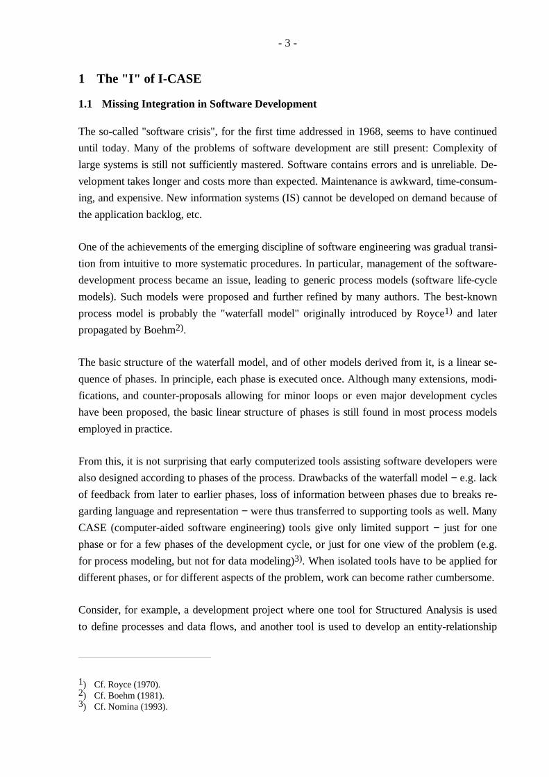
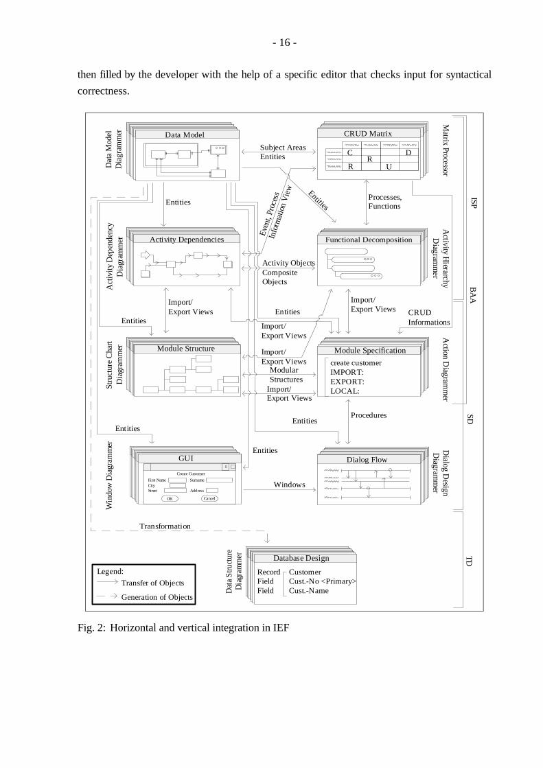
teleprocessing monitor, database management system, etc.). Figure 2 shows major IEF tools
for the first four stages. These tools will be briefly outlined before information exchange
between them is described.
The IEF tool set includes tools for defining and representing matrices (Matrix Processor), ER
diagrams (Data Model Diagrammer), and hierarchy diagrams (Activity Hierarchy Diagrammer
and Organizational Hierarchy Diagrammer). The Activity Dependency Diagrammer is used to
model sequences of functions and processes. (e.g. process A is executed subsequent to process
B). Procedural logic of elementary processes and procedures (procedures include their own
procedural logic and call elementary processes) is specified by means of the Action Diagram-
mer. The Structure Chart Diagrammer is used to process calling structures between elementary
processes. The Dialog Design Diagrammer is applied to process calling structures between
procedures. With the help of the Data Structure Diagrammer, the relational schema generated
from the ER model can be optimized. The Window Diagrammer enables the developer to
define a graphical user interface.
4.2 Horizontal Integration
IEF's encyclopedia is also a central encyclopedia with respect to the tool view, but not with re-
gard to interpersonal cooperation. IEF's concept of horizontal integration corresponds largely
to the concept outlined for ADW. Objects and information about object relationships are ex-
changed between tools via the encyclopedia. In addition, it is possible to link information in a
way that new objects will be derived automatically. This concept is illustrated by the following
example.
During analysis, procedural logic of elementary processes is specified by the developer. For
each elementary process, IEF generates a template that already contains import and export
views, the specified data accesses (create, update, etc.), and standard exception handling.
Information necessary to generate action blocks is taken from the process vs. entity-type
matrix or from statements of expected effects given by the developer. Expected effects describe
how entity types of the data model are accessed (read, write, etc.). Action block templates are
19) Cf. Texas Instruments Inc. (1993).
- 16 -
then filled by the developer with the help of a specific editor that checks input for syntactical
correctness.
Dat
a M
odel
Dia
gram
mer
Subject AreasEntities
Matrix P
rocessor A
ctivity Hierarchy
Diagram
mer
Act
ivity
Dep
ende
ncy
Dia
gram
mer
Action D
iagramm
erS
truc
ture
Cha
rt
Dia
gram
mer
Win
dow
Dia
gram
mer
Dialog D
esign D
iagramm
er
Dat
a S
truct
ure
Dia
gram
mer
Processes,Functions
Generation of Objects
Transfer of Objects
Legend:
Activity Objects CompositeObjects
Import/Export Views
Entities
Modular Structures
Transformation
Even
t, Pr
oces
sIn
form
atio
n V
iew
Procedures
Importance Response TimeImportance Response Time
ZieleData Model
R
C
R
UR
CR
U
D
CRUD Matrix
Activity Dependencies Functional Decomposition
Module SpecificationModule Structure
Entities
EntitiesEntities CRUD
Informations
create customerIMPORT:EXPORT:LOCAL:
Entities
GUI
Create Customer
First Name SurnameCityStreet Address
CancelOK
Windows
Dialog Flow
Entities
Database Design
RecordFieldField
CustomerCust.-No <Primary>Cust.-Name
SD
BA
ATD
ISP
Import/Export Views
Entities
Import/Export Views
Import/Export Views
Import/Export Views
Fig. 2: Horizontal and vertical integration in IEF
- 17 -
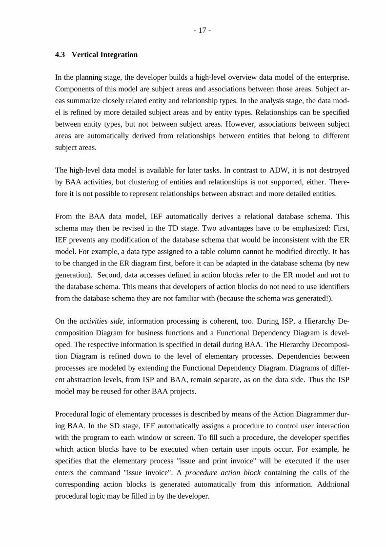
4.3 Vertical Integration
In the planning stage, the developer builds a high-level overview data model of the enterprise.
Components of this model are subject areas and associations between those areas. Subject ar-
eas summarize closely related entity and relationship types. In the analysis stage, the data mod-
el is refined by more detailed subject areas and by entity types. Relationships can be specified
between entity types, but not between subject areas. However, associations between subject
areas are automatically derived from relationships between entities that belong to different
subject areas.
The high-level data model is available for later tasks. In contrast to ADW, it is not destroyed
by BAA activities, but clustering of entities and relationships is not supported, either. There-
fore it is not possible to represent relationships between abstract and more detailed entities.
From the BAA data model, IEF automatically derives a relational database schema. This
schema may then be revised in the TD stage. Two advantages have to be emphasized: First,
IEF prevents any modification of the database schema that would be inconsistent with the ER
model. For example, a data type assigned to a table column cannot be modified directly. It has
to be changed in the ER diagram first, before it can be adapted in the database schema (by new
generation). Second, data accesses defined in action blocks refer to the ER model and not to
the database schema. This means that developers of action blocks do not need to use identifiers
from the database schema they are not familiar with (because the schema was generated!).
On the activities side, information processing is coherent, too. During ISP, a Hierarchy De-
composition Diagram for business functions and a Functional Dependency Diagram is devel-
oped. The respective information is specified in detail during BAA. The Hierarchy Decomposi-
tion Diagram is refined down to the level of elementary processes. Dependencies between
processes are modeled by extending the Functional Dependency Diagram. Diagrams of differ-
ent abstraction levels, from ISP and BAA, remain separate, as on the data side. Thus the ISP
model may be reused for other BAA projects.
Procedural logic of elementary processes is described by means of the Action Diagrammer dur-
ing BAA. In the SD stage, IEF automatically assigns a procedure to control user interaction
with the program to each window or screen. To fill such a procedure, the developer specifies
which action blocks have to be executed when certain user inputs occur. For example, he
specifies that the elementary process "issue and print invoice" will be executed if the user
enters the command "issue invoice". A procedure action block containing the calls of the
corresponding action blocks is generated automatically from this information. Additional
procedural logic may be filled in by the developer.
- 18 -
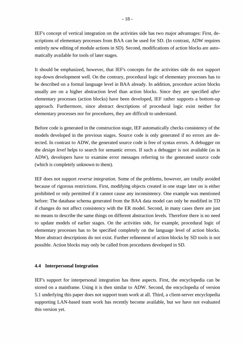
IEF's concept of vertical integration on the activities side has two major advantages: First, de-
scriptions of elementary processes from BAA can be used for SD. (In contrast, ADW requires
entirely new editing of module actions in SD). Second, modifications of action blocks are auto-
matically available for tools of later stages.
It should be emphasized, however, that IEF's concepts for the activities side do not support
top-down development well. On the contrary, procedural logic of elementary processes has to
be described on a formal language level in BAA already. In addition, procedure action blocks
usually are on a higher abstraction level than action blocks. Since they are specified after
elementary processes (action blocks) have been developed, IEF rather supports a bottom-up
approach. Furthermore, since abstract descriptions of procedural logic exist neither for
elementary processes nor for procedures, they are difficult to understand.
Before code is generated in the construction stage, IEF automatically checks consistency of the
models developed in the previous stages. Source code is only generated if no errors are de-
tected. In contrast to ADW, the generated source code is free of syntax errors. A debugger on
the design level helps to search for semantic errors. If such a debugger is not available (as in
ADW), developers have to examine error messages referring to the generated source code
(which is completely unknown to them).
IEF does not support reverse integration. Some of the problems, however, are totally avoided
because of rigorous restrictions. First, modifying objects created in one stage later on is either
prohibited or only permitted if it cannot cause any inconsistency. One example was mentioned
before: The database schema generated from the BAA data model can only be modified in TD
if changes do not affect consistency with the ER model. Second, in many cases there are just
no means to describe the same things on different abstraction levels. Therefore there is no need
to update models of earlier stages. On the activities side, for example, procedural logic of
elementary processes has to be specified completely on the language level of action blocks.
More abstract descriptions do not exist. Further refinement of action blocks by SD tools is not
possible. Action blocks may only be called from procedures developed in SD.
4.4 Interpersonal Integration
IEF's support for interpersonal integration has three aspects. First, the encyclopedia can be
stored on a mainframe. Using it is then similar to ADW. Second, the encyclopedia of version
5.1 underlying this paper does not support team work at all. Third, a client-server encyclopedia
supporting LAN-based team work has recently become available, but we have not evaluated
this version yet.
- 19 -
One encyclopedia, used by all tools
No redundancy
Results of one tool are immediately available for other tools
Hor
izon
tal
inte
grat
ion
ADW IEF
One encyclopedia, used by all tools
No redundancy
Results of one tool are immediately available for other tools
Ver
tical
inte
gra
tion
Rev
erse
inte
grat
ion
For
war
d in
tegr
atio
n
Straightforward mechanisms for functions and processes
Weak integration from BAA to SD for processes (minispecifications are just comments, no furtherautomatic processing or translation to module specifications)
Generation of formal parameter lists and callsof modules in module action diagrams(version 2.7)
No support for ER model clustering
Modifications in the ER model in BAA caneasily be taken over to SD in version 2.7(in version 1.6 this is a error-prone and time-consuming task)
Straightforward mechanisms for functions and processes
No mechanisms for refining procedural logic
No support for ER model clustering
Refinement of subject areas by subject areas, entities and relationships
Break between BAA and SD, changes of data definitions in SD can cause inconsistencies between SD and BAA models and vice versa
No need for reverse integration, consistency is supported by
- restricting permissible modifications of data definitions
- avoiding different abstraction levels for activities
Mainframe-based encyclopedia with multi-user capability
Awkward consolidation mechanism for parallel encyclopedias
LAN-based encyclopedia with multi-user capability (version 2.7)
Mainframe-based encyclopedia with multi-user capability
LAN-based encyclopedia with multi-user capability
Inte
rper
sona
l in
tegr
atio
n
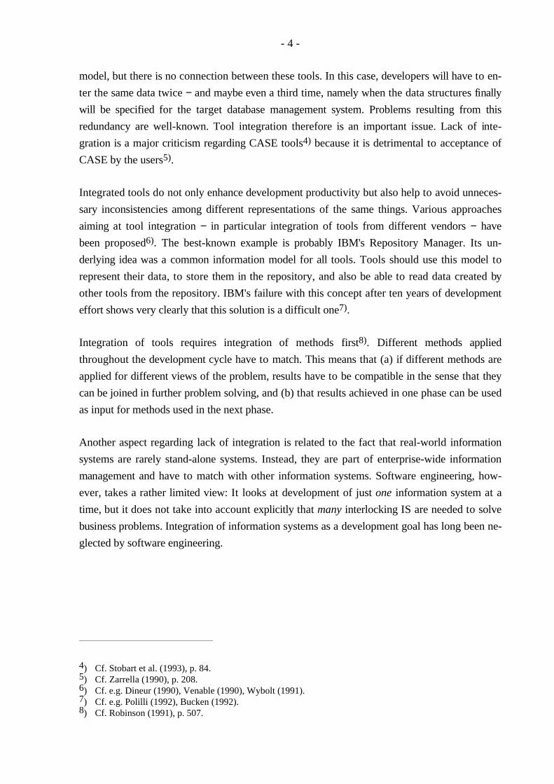
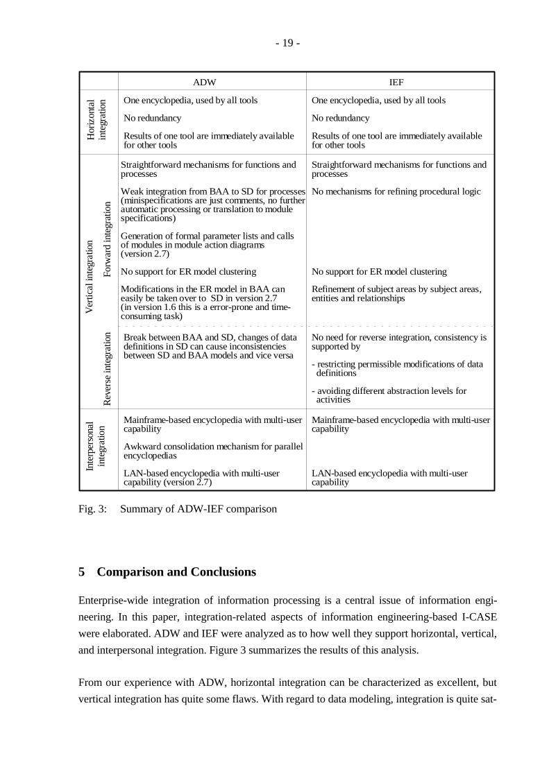
Fig. 3: Summary of ADW-IEF comparison
5 Comparison and Conclusions
Enterprise-wide integration of information processing is a central issue of information engi-
neering. In this paper, integration-related aspects of information engineering-based I-CASE
were elaborated. ADW and IEF were analyzed as to how well they support horizontal, vertical,
and interpersonal integration. Figure 3 summarizes the results of this analysis.
From our experience with ADW, horizontal integration can be characterized as excellent, but
vertical integration has quite some flaws. With regard to data modeling, integration is quite sat-

- 20 -
isfactory across ISP and BAA stages, but integration between BAA and SD needs to be im-
proved considerably. On the other hand, the activities side suffers severely from lack of inte-
grative features. Interpersonal integration has also been weak up to now and only recently been
improved. The old concept of consolidation across encyclopedias was insufficient for efficient
support of project work20). The Workgroup Coordinator promises to remedy this drawback.
IEF tools, compared to ADW, appear to be better integrated. Whereas horizontal integration is
about the same, vertical integration has significant advantages over ADW's concepts. Not only
the tools for data modeling are integrated across stages, but the tools creating successive rep-
resentations of activities (processes, procedures, programs) are integrated, too. Program-con-
struction and design tools are integrated better than in ADW. This is particularly useful when it
comes to debugging. Whereas ADW developers have to scan Cobol code for semantic errors,
IEF provides a high-level debugger on the pseudo-code level (i.e. for process-action code). In
addition, IEF prevents some problems from missing reverse integration, as mentioned in
chapter 4.3.
Both ADW and IEF have been employed in large real-world projects. General Electrics, for
example used ADW to develop a system which connects offers, orders and shipping
information into a single sales information system21). Ford of Germany applied information
engineering methodology supported by IEF in several projects. TWA developed their frequent-
flyer bonus system of 1.5 million lines of code with IEF. Since it was so successful, they sold it
to Lufthansa who developed their miles-and-more program based on it within half a year. All
these users claim significant productivity gains as compared to conventional IS development.
On the other hand, I-CASE failures are likely to have occurred, too, but they are rarely
reported in literature. Many potential users still hesitate, being uncertain whether the overhead
of information engineering-based I-CASE really pays.
References
Batini, C., Ceri, S., Navathe B.: Conceptual database design: an Entity-Relationship Approach;Redwood City 1992.
Boehm, B. W.: Software Engineering Economics; Englewood Cliffs 1981.
Bucken, M.: AD/Cycle Changes Continue; Software Magazine 12 (1992) 14, pp. 26-30.
20) Cf. Kurbel (1994).21) Cf. Douglass, Walsh (1993).
- 21 -
Douglass, D. P., Walsh, L.: The Costs and Benefits of CASE; I/S Analyser 31 (1993) 6.
Dineur, A.: ATMOSPHERE: CASE for System Engineering Support; in: Norman, R. J., Van Ghent, R.(Eds.): Fourth International Workshop on Computer-Aided Software Engineering; Los Alamitos,Washington et al. 1990, pp. 154-157.
Jaeschke, P., Oberweis, A., Stucky, W.: Extending ER Model Clustering by Relationship Clustering (toappear).
KnowledgeWare Inc.: Application Development Workbench - Overview, 0194-PU-0665, Knowledge-Ware Inc.; Atlanta, GA. 1994.
Kramer, J.: CASE Support for the Software Process: A Research Viewpoint; in: Van Lamsweerde, A.,Fugetta, A. (Eds.): Proceedings of the 3rd European Software Engineering Conference, LectureNotes in Computer Science 550; Berlin, Heidelberg et al., pp. 499-503.
Kurbel, K.: From Analysis to Code Generation: Experiences from an Information Engineering ProjectUsing I-CASE Technology; in: Wijers, G., Brinkkemper, S., Wasserman, T. (Eds.): AdvancedInformation Systems Engineering, 6th International Conference, CAiSE '94, Proceedings, LectureNotes in Computer Science 811; Berlin, Heidelberg et al., pp. 214-227.
Garbajosa, J., Jarre, J. R. et al.: Position Paper: Implementing Cooperation and Coordination in Soft-ware Engineering Environments; in: Norman, R. J., Van Ghent, R. (Eds.): Fourth InternationalWorkshop on Computer-Aided Software Engineering; Los Alamitos, Washington et al. 1990, pp.163-167.
Markowitz, V. M., Shoshani, A.: Representing Extended Entity-Relationship Structures in RelationalDatabases: A Modular Approach; ACM Transactions on Database Systems 17 (1992) 3, pp. 423-464.
Martin, J.: Information Engineering, Book I Introduction; Englewood Cliffs 1989.
McCormack, J. I., Halpin, T. A., Ritson, P. R.: Automated mapping of conceptual schemas to relationalschemas; in: Rolland, R., Bodart, F., Cauvet, C. (Eds.): Advanced Information Systems Engineer-ing, 5th International Conference, CAiSE '93, Lecture Notes in Computer Science 685; Berlin,Heidelberg et al.1993, pp. 432-448.
Nomina Gesellschaft für Wirtschafts- und Verwaltungsregister: ISIS PC Report, Software für PersonalComputer & PC-Netzwerke, Vol. 2; München 1993.
Polilli, S.: IBM Redirects AD/Cycle, Software Magazine 12 (1992) 12, pp. 31-34.
Rauh, O., Stickel, E.: Entity tree clustering - A method for simplifying ER design; in: Pernul, G., Tjoa,A. M. (Eds.): Proceedings of the 11th International Conference on Entity-Relationship Approach;Berlin, Heidelberg et al. 1992, pp. 62-78.
Robinson, D.: CASE Support For Large Systems; in: Van Lamsweerde, A., Fugetta, A. (Eds.): Pro-ceedings of the 3rd European Software Engineering Conference, Lecture Notes in Computer Science550; Berlin, Heidelberg et al. 1991, pp. 504-508.
Royce, W. W.: Managing the development of large software systems: concepts and techniques; in:Proceedings of Western electronic show and convention '70; Los Angeles 1970.
- 22 -
Stobart, S. C., van Reeken, A. J. et al.: An Empirical Evaluation of the Use of CASE Tools; in: Lee,H.-Y., Reid, T. F., Jarzabek, S. (Eds.): Proceedings of the Sixth International Workshop onComputer-Aided Software Engineering; Los Alamitos, Washington et al. 1993, pp. 81-87.
Teorey, T. J., Yang, D., Fry, J. P.: ER model clustering as an aid for user communication and documen-tation in database design; Communications of the ACM, 32 (1989) 8, pp. 975-987.
Texas Instruments Inc.: Developer's Reference, 2632047-7301, Texas Instruments Inc.; Plano, Texas1993.
Venable, J. R.: Achieving Effective Tool Integration in a CASE Environment; in: Norman, R. J., VanGhent, R. (Eds.): Fourth International Workshop on Computer-Aided Software Engineering; LosAlamitos, Washington et al. 1990, pp. 204-205.
Wybolt, N.: Perspectives on CASE Tool Integration; Software Engineering Notes, 16 (1991) 3, pp. 56-60.
Zarrella, P. F.: CASE Tool Integration and Standardization; in: Norman, R. J., Van Ghent, R. (Eds.):Fourth International Workshop on Computer-Aided Software Engineering; Los Alamitos,Washington et al. 1990, pp. 208-209.
- 23 -
Arbeitsberichte des Instituts für Wirtschaftsinformatik
Nr. 1 Bolte, Ch., Kurbel, K., Moazzami, M., Pietsch, W.: Erfahrungen bei der Entwicklung eines In-formationssystems auf RDBMS- und 4GL-Basis; Februar 1991.
Nr. 2 Kurbel, K.: Das technologische Umfeld der Informationsverarbeitung - Ein subjektiver 'State ofthe Art'-Report über Hardware, Software und Paradigmen; März 1991.
Nr. 3 Kurbel, K.: CA-Techniken und CIM; Mai 1991.
Nr. 4 Nietsch, M., Nietsch, T., Rautenstrauch, C., Rinschede, M., Siedentopf, J.: Anforderungenmittelständischer Industriebetriebe an einen elektronischen Leitstand - Ergebnisse einer Untersu-chung bei zwölf Unternehmen; Juli 1991.
Nr. 5 Becker, J., Prischmann, M.: Konnektionistische Modelle - Grundlagen und Konzepte; Septem-ber 1991.
Nr. 6 Grob, H.L.: Ein produktivitätsorientierter Ansatz zur Evaluierung von Beratungserfolgen; Sep-tember 1991.
Nr. 7 Becker, J.: CIM und Logistik; Oktober 1991.
Nr. 8 Burgholz, M., Kurbel, K., Nietsch, Th., Rautenstrauch, C.: Erfahrungen bei der Entwicklungund Portierung eines elektronischen Leitstands; Januar 1992.
Nr. 9 Becker, J., Prischmann, M.: Anwendung konnektionistischer Systeme; Februar 1992.
Nr. 10 Becker, J.: Computer Integrated Manufacturing aus Sicht der Betriebswirtschaftslehre und derWirtschaftsinformatik; April 1992.
Nr. 11 Kurbel, K., Dornhoff, P.: A System for Case-Based Effort Estimation for Software-Develop-ment Projects; Juli 1992.
Nr. 12 Dornhoff, P.: Aufwandsplanung zur Unterstützung des Managements von Softwareentwick-lungsprojekten; August 1992.
Nr. 13 Eicker, S., Schnieder, T.: Reengineering; August 1992.
Nr. 14 Erkelenz, F.: KVD2 - Ein integriertes wissensbasiertes Modul zur Bemessung von Kranken-hausverweildauern - Problemstellung, Konzeption und Realisierung; Dezember 1992.
Nr. 15 Horster, B., Schneider, B., Siedentopf, J.: Kriterien zur Auswahl konnektionistischer Verfahrenfür betriebliche Probleme; März 1993.
Nr. 16 Jung, R.: Wirtschaftlichkeitsfaktoren beim integrationsorientierten Reengineering: Verteilungs-architektur und Integrationsschritte aus ökonomischer Sicht; Juli 1993.
Nr. 17 Miller, C., Weiland, R.: Der Übergang von proprietären zu offenen Systemen aus Sicht derTransaktionskostentheorie; Juli 1993.
Nr. 18 Becker, J., Rosemann, M.: Design for Logistics - Ein Beispiel für die logistikgerechte Gestal-tung des Computer Integrated Manufacturing; Juli 1993.
Nr. 19 Becker, J., Rosemann, M.: Informationswirtschaftliche Integrationsschwerpunkte innerhalb derlogistischen Subsysteme - Ein Beitrag zu einem produktionsübergreifenden Verständnis vonCIM; Juli 1993.
- 24 -
Nr. 20 Becker, J.: Neue Verfahren der entwurfs- und konstruktionsbegleitenden Kalkulation und ihreGrenzen in der praktischen Anwendung; Juli 1993.
Nr. 21 Becker, K., Prischmann, M.: VESKONN - Prototypische Umsetzung eines modularen Konzeptszur Konstruktionsunterstützung mit konnektionistischen Methoden; November 1993
Nr. 22 Schneider, B.: Neuronale Netze für betriebliche Anwendungen: Anwendungspotentiale undexistierende Systeme; November 1993.
Nr. 23 Nietsch, T., Rautenstrauch, C., Rehfeldt, M., Rosemann, M., Turowski, K.: Ansätze für dieVerbesserung von PPS-Systemen durch Fuzzy-Logik; Dezember 1993.
Nr. 24 Nietsch, M., Rinschede, M., Rautenstrauch, C.: Werkzeuggestützte Individualisierung desobjektorientierten Leitstands ooL, Dezember 1993.
Nr. 25 Meckenstock, A., Unland, R., Zimmer, D.: Flexible Unterstützung kooperativer Entwurfsumge-bungen durch einen Transaktions-Baukasten, Dezember 1993.
Nr. 26 Grob, H. L.: Computer Assisted Learning (CAL) durch Berechnungsexperimente, Januar 1994.
Nr. 27 Kirn, St., Unland, R. (Hrsg.): Tagungsband zum Workshop "Unterstützung OrganisatorischerProzesse durch CSCW". In Kooperation mit GI-Fachausschuß 5.5 "Betriebliche Kommunika-tions- und Informationssysteme" und Arbeitskreis 5.5.1 "Computer Supported CooperativeWork", Westfälische Wilhelms-Universität Münster, 4.-5. November 1993
Nr. 28 Kirn, St., Unland, R.: Zur Verbundintelligenz integrierter Mensch-Computer-Teams: Ein orga-nisationstheoretischer Ansatz, März 1994.
Nr. 29 Kirn, St., Unland, R.: Workflow Management mit kooperativen Softwaresystemen: State of theArt und Problemabriß, März 1994.
Nr. 30 Unland, R.: Optimistic Concurrency Control Revisited, März 1994.
Nr. 31 Unland, R.: Semantics-Based Locking: From Isolation to Cooperation, März 1994.
Nr. 32 Meckenstock, A., Unland, R., Zimmer, D.: Controlling Cooperation and Recovery in NestedTransactions, März 1994.
Nr. 33 Kurbel, K., Schnieder, T.: Integration Issues of Information Engineering Based I-CASE Tools,September 1994.