Investigation of pulsed actuators for active flow control...
8
1 Investigation of pulsed actuators for active flow control using phase locked stereoscopic Particle Image Velocimetry by J. Ortmanns (1) and C. J. Kähler (2) Institut für Strömungsmechanik, TU Braunschweig Bienroder Weg 3, 38106 Braunschweig, Germany (1) E-Mail: [email protected] (2) E-Mail: [email protected] ABSTRACT The dynamic behaviour of two pulsed pneumatic actuators were examined to understand first the effect of the system parameter (frequency, duty-cycle, waveform, pressure, actuator volume and feed line length) on the output signal, and second, the interaction of the actuator jet with a turbulent boundary layer. The investigation indicates that the skewed jet becomes most efficient for boundary layer control when the output-velocity has a span-wise component. In this case a strong large scale secondary flow is generated, due to the asymmetric injection of the fluid, which transfers high mo- mentum fluid from the outer part of the boundary layer in the near wall region. Blowing with a strong component in stream-wise direction, on the other hand, seems to be less efficient, relative to the oblique one, because of the small effect in span-wise direction and the momentum loss of the jet due to turbulent mixing and viscosity. In case of the rec- tangular actuator it could be demonstrated that the efficiency decreases when the orientation of the actuator becomes perpendicular to the main flow direction. In this case no asymmetric large scale vortex structure is generated which transfers high momentum fluid from the outer region of the boundary layer towards the wall. Finally, it could be shown that the momentum pattern of the dynamic jets becomes very similar to the static ones shortly after opening the valve. However, during the opening and closing of the valve, a strong span-wise modulation of the base flow can be observed that stimulates the mixing. 1. INTRODUCTION The control of boundary layer flow separation by means of synthetic jets is a well established method that has been frequently applied in many fields of fundamental and applied fluid mechanics. The actuation can be done directly, by transferring momentum into the desired region by means of tangential blowing (Chang, 1976), or indirectly. In this case, the blockage of the actuator jet is exploited to enhance the mixing of the base flow, similar to mechanical vortex generators (Johnston and Nishi 1990). In the past many attempts have been made to replace the stationary blowing ac- tuators in favour of dynamic ones (Gad-el-Hak, 2001, McManus et. al. 1996). The motivation for the use of these ac- tuators is the higher efficiency, due to the reduced mass flux, and the excitation of new turbulent structures which pro- mote the mixing, such as starting vortices for instance. Johari and Rixon (2003) observed that with the dynamic actua- tion an increase of approximately 30 % of peak vorticity and a penetration of 50 % farther into the boundary layer can be achieved. However, due to the large amount of control parameter required for the operation of these pulsed actua- tors, many investigations have been performed to optimize the parameter for different applications. Compton and Johnston (1992) have varied the skew angle of a single round jet with fixed pitch angle at 45 deg and pointed out that a skew angle of 90 deg is an optimal configuration to produce a strong stream-wise vortex. McManus et.al. (1996) showed that the ratio between the jet diameter and the boundary layer thickness should be around four for an efficient control. Nagib et.al. (2001) concluded from the analysis of several experiments that the reduced frequency must be ap- proximately one. In addition they describe that the most effective location for unsteady forcing is near the point of separation. The influence of the duty-cycle ∆, defined as the opening time of the valve relative to the time of one pe- riod, is another operational parameter discussed in the literature, because it leads to a variation of the durability of the starting vortex ring. In the present investigation, the dynamic behaviour of different pneumatic actuators where exam- ined systematically to examine the physics of the mixing process and the potential of the actuators for flow control ap-
Transcript of Investigation of pulsed actuators for active flow control...
1
Investigation of pulsed actuators for active flow control using
phase locked stereoscopic Particle Image Velocimetry
by
J. Ortmanns(1) and C. J. Kähler(2)
Institut für Strömungsmechanik, TU Braunschweig
Bienroder Weg 3, 38106 Braunschweig, Germany (1)E-Mail: [email protected]
(2)E-Mail: [email protected]
ABSTRACT
The dynamic behaviour of two pulsed pneumatic actuators were examined to understand first the effect of the system parameter (frequency, duty-cycle, waveform, pressure, actuator volume and feed line length) on the output signal, and second, the interaction of the actuator jet with a turbulent boundary layer. The investigation indicates that the skewed jet becomes most efficient for boundary layer control when the output-velocity has a span-wise component. In this case a strong large scale secondary flow is generated, due to the asymmetric injection of the fluid, which transfers high mo-mentum fluid from the outer part of the boundary layer in the near wall region. Blowing with a strong component in stream-wise direction, on the other hand, seems to be less efficient, relative to the oblique one, because of the small effect in span-wise direction and the momentum loss of the jet due to turbulent mixing and viscosity. In case of the rec-tangular actuator it could be demonstrated that the efficiency decreases when the orientation of the actuator becomes perpendicular to the main flow direction. In this case no asymmetric large scale vortex structure is generated which transfers high momentum fluid from the outer region of the boundary layer towards the wall. Finally, it could be shown that the momentum pattern of the dynamic jets becomes very similar to the static ones shortly after opening the valve. However, during the opening and closing of the valve, a strong span-wise modulation of the base flow can be observed that stimulates the mixing.
1. INTRODUCTION
The control of boundary layer flow separation by means of synthetic jets is a well established method that has been frequently applied in many fields of fundamental and applied fluid mechanics. The actuation can be done directly, by transferring momentum into the desired region by means of tangential blowing (Chang, 1976), or indirectly. In this case, the blockage of the actuator jet is exploited to enhance the mixing of the base flow, similar to mechanical vortex generators (Johnston and Nishi 1990). In the past many attempts have been made to replace the stationary blowing ac-tuators in favour of dynamic ones (Gad-el-Hak, 2001, McManus et. al. 1996). The motivation for the use of these ac-tuators is the higher efficiency, due to the reduced mass flux, and the excitation of new turbulent structures which pro-mote the mixing, such as starting vortices for instance. Johari and Rixon (2003) observed that with the dynamic actua-tion an increase of approximately 30 % of peak vorticity and a penetration of 50 % farther into the boundary layer can be achieved. However, due to the large amount of control parameter required for the operation of these pulsed actua-tors, many investigations have been performed to optimize the parameter for different applications. Compton and Johnston (1992) have varied the skew angle of a single round jet with fixed pitch angle at 45 deg and pointed out that a skew angle of 90 deg is an optimal configuration to produce a strong stream-wise vortex. McManus et.al. (1996) showed that the ratio between the jet diameter and the boundary layer thickness should be around four for an efficient control. Nagib et.al. (2001) concluded from the analysis of several experiments that the reduced frequency must be ap-proximately one. In addition they describe that the most effective location for unsteady forcing is near the point of separation. The influence of the duty-cycle ∆, defined as the opening time of the valve relative to the time of one pe-riod, is another operational parameter discussed in the literature, because it leads to a variation of the durability of the starting vortex ring. In the present investigation, the dynamic behaviour of different pneumatic actuators where exam-ined systematically to examine the physics of the mixing process and the potential of the actuators for flow control ap-
2
plications in the future. Of particular interest was the response of the actuators as a function of the frequency f, duty cycle ∆, waveform, pressure pV, actuator volume V and feed line length lS. For this investigation a commercial high speed magnetic valve of low cost, small size and sufficient robustness was applied because by using this device it be-comes possible to vary the frequency and amplitude independently. The response of the pulsed actuator to the input signal of the frequency generator was investigated with a hot-wire probe and a phased-locked stereoscopic and time resolved PIV system. After the determination of the optimized operation parameter, a flat plate boundary layer experi-ment was performed to examine the effect of the actuators on the properties of the flow. Although such investigations are quite challenging due to the strong velocity variations, the small area of the actuator outlets and the difficulties as-sociated with the injection of the particles inside the dynamic actuator, the dynamical behaviour of the actuators can be determined as will be seen in the following.
2. PRELIMINARY INVESTIGATION
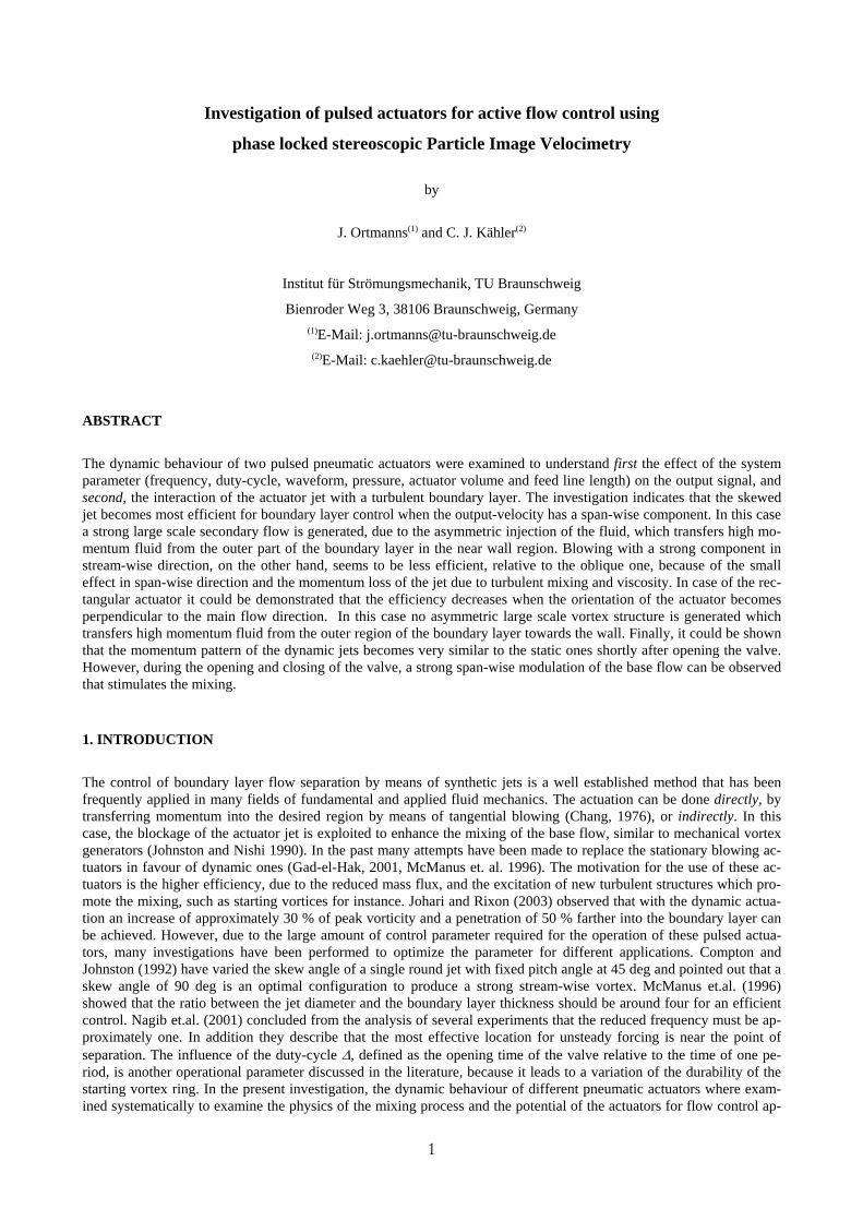
It is obvious that the flow structure of the jet and its response to an input signal depends on the design of the actuator. Beside the geometry and the size of the exit area S, the volume of the settling chamber V and the length of the feed line lS are of primary importance. The volume of the settling chamber for example should be large to avoid in-homogeneities due to the piston, but small to avoid a significant damping or modification of the output velocity signal. For the investigation a modular construction that supports inlets with different size, geometries and orientation and a continuous variation of the volume V and tube length lS was designed, see figure 1. In the present investigation a round jet-inlet with a 1 and 2 mm diameter drill and a rectangular one with a variable aspect ratio in the range b = 5 – 20 mm (width) and h = 0 – 2 mm (height) was studied. A variation of the pitch α and the skew angle β in the range of α = 30 – 90 deg and β = 0 – 180 deg can be adjusted in addition. This becomes important for the investigation outlined in the next section. The poppet valve is a commercial MH2 fast-switching valve from FESTO with a maximum switching fre-quency of 150 Hz. It has an operating pressure range from -0.9 to +8 bar and a response time of 2 ms ± 10 %. The feed pressure is held constant at pV = 1.5 bar at a line position of lp = 3.5 m in front of the valve. The timing control takes place with a HAMEG 8131-2 function generator which allows to adjust the frequency f and duty cycle ∆. Because of the valve design – the switch at a defined threshold voltage value – only rectangular input signals can be processed. For waveform investigations the FESTO MPYE-5 has to be applied, but this device has a maximum frequency of 100 Hz and an increasing leakage at high frequencies.
The dynamic behavior of the pulsed pneumatic actuator was investigated with a constant temperature hot-wire ane-mometer (Dantec CTA 56C01/CTA Bridge 56C17 system with a single probe 55P12). To preclude a mirror effect of the probe temperature the distance between the hot-wire probe and the jet-orifice was set to z = 1 mm. The valve driv-ing signal of the frequency generator and the probe signal were sampled using a LeCroy Digital Oscilloscope with a sample rate of 104 samples/second. A phase locked mean value was calculated based on 100 sweeps.
Actuator inlet
Piston
Valve
Retainer
lSlp
Fig. 1. Actuator concept with a variable adjust-
ment of the volume V, the tube length lS
and a flexible change of the jet exit area by
using inlets.
V
3
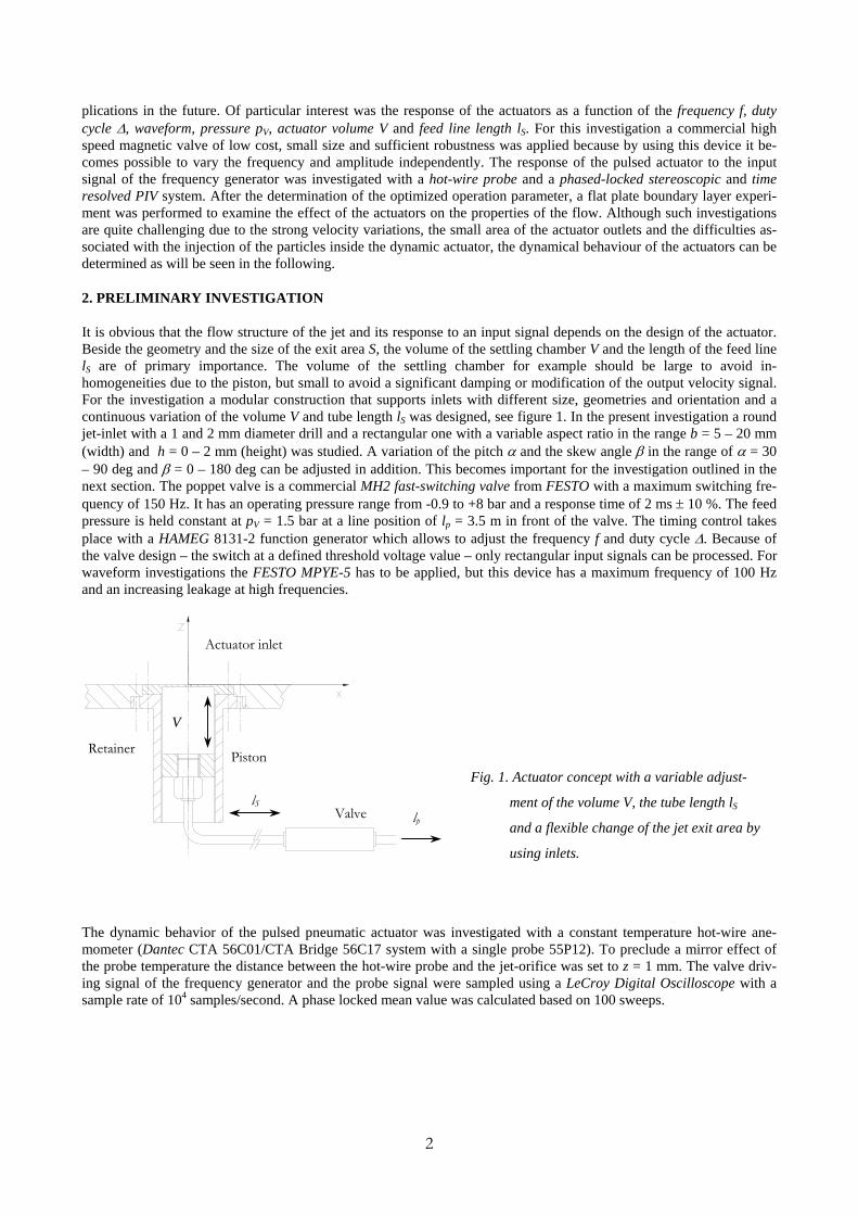
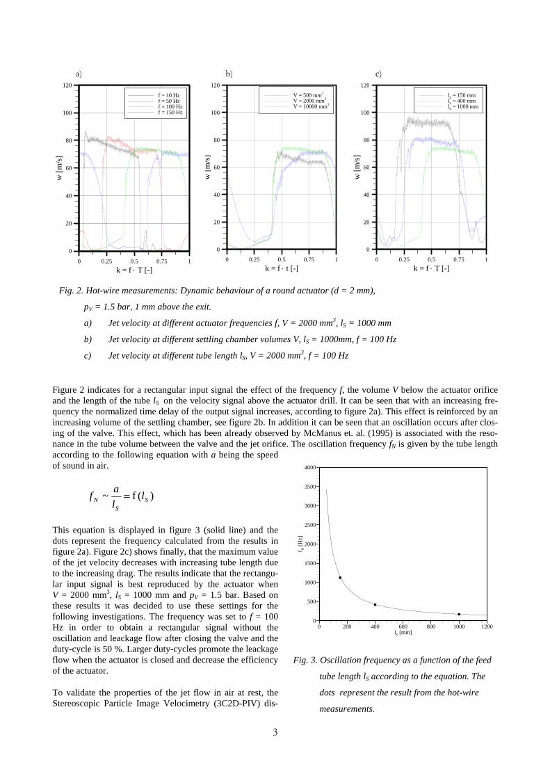
Figure 2 indicates for a rectangular input signal the effect of the frequency f, the volume V below the actuator orifice and the length of the tube lS on the velocity signal above the actuator drill. It can be seen that with an increasing fre-quency the normalized time delay of the output signal increases, according to figure 2a). This effect is reinforced by an increasing volume of the settling chamber, see figure 2b. In addition it can be seen that an oscillation occurs after clos-ing of the valve. This effect, which has been already observed by McManus et. al. (1995) is associated with the reso-nance in the tube volume between the valve and the jet orifice. The oscillation frequency fN is given by the tube length according to the following equation with a being the speed of sound in air.
)(f~ SS
N llaf =
This equation is displayed in figure 3 (solid line) and the dots represent the frequency calculated from the results in figure 2a). Figure 2c) shows finally, that the maximum value of the jet velocity decreases with increasing tube length due to the increasing drag. The results indicate that the rectangu-lar input signal is best reproduced by the actuator when V = 2000 mm3, lS = 1000 mm and pV = 1.5 bar. Based on these results it was decided to use these settings for the following investigations. The frequency was set to f = 100 Hz in order to obtain a rectangular signal without the oscillation and leackage flow after closing the valve and the duty-cycle is 50 %. Larger duty-cycles promote the leackage flow when the actuator is closed and decrease the efficiency of the actuator.
To validate the properties of the jet flow in air at rest, the Stereoscopic Particle Image Velocimetry (3C2D-PIV) dis-
k = f ⋅ T [-]
w[m
/s]
0 0.25 0.5 0.75 1
0
20
40
60
80
100
120lS = 150 mmlS = 400 mmlS = 1000 mm
k = f ⋅ t [-]
w[m
/s]
0 0.25 0.5 0.75 1
0
20
40
60
80
100
120V = 500 mm3
V = 2000 mm3
V = 10000 mm3
k = f ⋅ T [-]
w[m
/s]
0 0.25 0.5 0.75 1
0
20
40
60
80
100
120f = 10 Hzf = 50 Hzf = 100 Hzf = 150 Hz
a) b) c)
Fig. 2. Hot-wire measurements: Dynamic behaviour of a round actuator (d = 2 mm),
pV = 1.5 bar, 1 mm above the exit.
a) Jet velocity at different actuator frequencies f, V = 2000 mm3, lS = 1000 mm
b) Jet velocity at different settling chamber volumes V, lS = 1000mm, f = 100 Hz
c) Jet velocity at different tube length lS, V = 2000 mm3, f = 100 Hz
lS [mm]
f N[H
z]
0 200 400 600 800 1000 12000
500
1000
1500
2000
2500
3000
3500
4000
Fig. 3. Oscillation frequency as a function of the feed
tube length lS according to the equation. The
dots represent the result from the hot-wire
measurements.
4
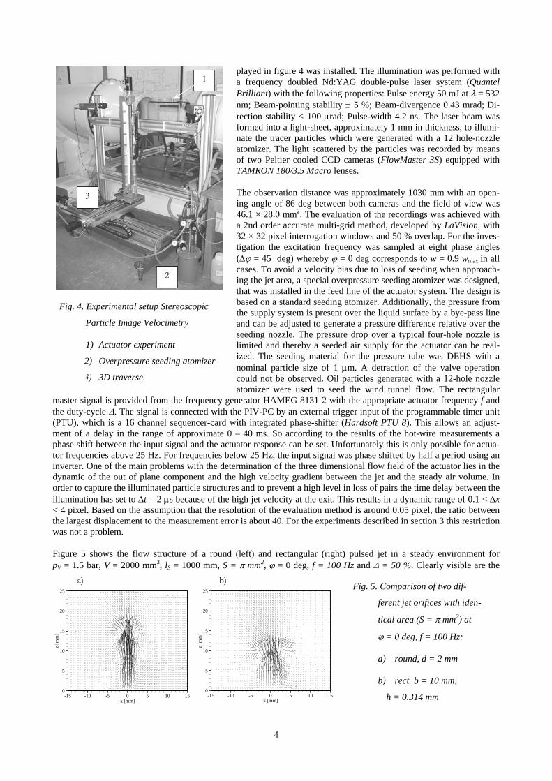
played in figure 4 was installed. The illumination was performed with a frequency doubled Nd:YAG double-pulse laser system (Quantel Brilliant) with the following properties: Pulse energy 50 mJ at λ = 532 nm; Beam-pointing stability ± 5 %; Beam-divergence 0.43 mrad; Di-rection stability < 100 µrad; Pulse-width 4.2 ns. The laser beam was formed into a light-sheet, approximately 1 mm in thickness, to illumi-nate the tracer particles which were generated with a 12 hole-nozzle atomizer. The light scattered by the particles was recorded by means of two Peltier cooled CCD cameras (FlowMaster 3S) equipped with TAMRON 180/3.5 Macro lenses.
The observation distance was approximately 1030 mm with an open-ing angle of 86 deg between both cameras and the field of view was 46.1 × 28.0 mm2. The evaluation of the recordings was achieved with a 2nd order accurate multi-grid method, developed by LaVision, with 32 × 32 pixel interrogation windows and 50 % overlap. For the inves-tigation the excitation frequency was sampled at eight phase angles (∆ϕ = 45 deg) whereby ϕ = 0 deg corresponds to w = 0.9 wmax in all cases. To avoid a velocity bias due to loss of seeding when approach-ing the jet area, a special overpressure seeding atomizer was designed, that was installed in the feed line of the actuator system. The design is based on a standard seeding atomizer. Additionally, the pressure from the supply system is present over the liquid surface by a bye-pass line and can be adjusted to generate a pressure difference relative over the seeding nozzle. The pressure drop over a typical four-hole nozzle is limited and thereby a seeded air supply for the actuator can be real-ized. The seeding material for the pressure tube was DEHS with a nominal particle size of 1 µm. A detraction of the valve operation could not be observed. Oil particles generated with a 12-hole nozzle atomizer were used to seed the wind tunnel flow. The rectangular
master signal is provided from the frequency generator HAMEG 8131-2 with the appropriate actuator frequency f and the duty-cycle ∆. The signal is connected with the PIV-PC by an external trigger input of the programmable timer unit (PTU), which is a 16 channel sequencer-card with integrated phase-shifter (Hardsoft PTU 8). This allows an adjust-ment of a delay in the range of approximate 0 – 40 ms. So according to the results of the hot-wire measurements a phase shift between the input signal and the actuator response can be set. Unfortunately this is only possible for actua-tor frequencies above 25 Hz. For frequencies below 25 Hz, the input signal was phase shifted by half a period using an inverter. One of the main problems with the determination of the three dimensional flow field of the actuator lies in the dynamic of the out of plane component and the high velocity gradient between the jet and the steady air volume. In order to capture the illuminated particle structures and to prevent a high level in loss of pairs the time delay between the illumination has set to ∆t = 2 µs because of the high jet velocity at the exit. This results in a dynamic range of 0.1 < ∆x < 4 pixel. Based on the assumption that the resolution of the evaluation method is around 0.05 pixel, the ratio between the largest displacement to the measurement error is about 40. For the experiments described in section 3 this restriction was not a problem.
Figure 5 shows the flow structure of a round (left) and rectangular (right) pulsed jet in a steady environment for pV = 1.5 bar, V = 2000 mm3, lS = 1000 mm, S = π mm2, ϕ = 0 deg, f = 100 Hz and ∆ = 50 %. Clearly visible are the
1
2
3
Fig. 4. Experimental setup Stereoscopic
Particle Image Velocimetry
1) Actuator experiment
2) Overpressure seeding atomizer
3) 3D traverse.
Fig. 5. Comparison of two dif-
ferent jet orifices with iden-
tical area (S = π mm2) at
ϕ = 0 deg, f = 100 Hz:
a) round, d = 2 mm
b) rect. b = 10 mm,
h = 0.314 mm x [mm]
z[m
m]
-15 -10 -5 0 5 10 150
5
10
15
20
25
x [mm]
z[m
m]
-15 -10 -5 0 5 10 150
5
10
15
20
25
a) b)
5
symmetric vortex structures, which are sections of the starting vortex, and the entrainment process in the wake of this vortex ring. A temporal sequence indicate that after closing the valve this flow structure moves away from the wall and the amplitude decreases gradually. The general flow characteristics show the same behaviour for all frequencies inves-tigated here (f = 10, 50, 100 and 150 Hz). Basically, the difference between the maximum jet velocity (compare figure 5a and b)) is a result of the losses due to the different length of the perimeter between both geometries by a factor of 3.28. The low axial velocity at the wall is a spatial averaging effect, because of the light sheet thickness of about 1 mm whereas the slot height has a dimension of h = 0.314 mm. An error may occur if the captured particle images represent a mean value of the fluid motion in the light sheet.
3. TURBULENT BOUNDARY LAYER CONTROL
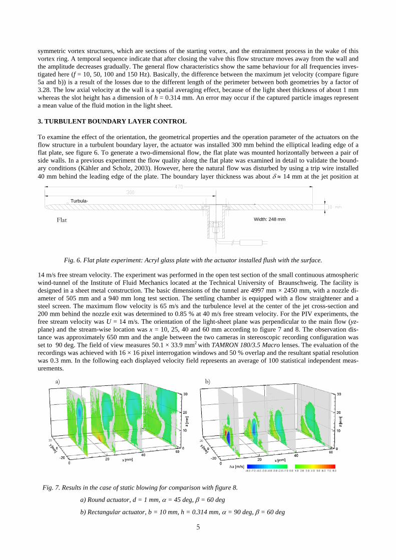
To examine the effect of the orientation, the geometrical properties and the operation parameter of the actuators on the flow structure in a turbulent boundary layer, the actuator was installed 300 mm behind the elliptical leading edge of a flat plate, see figure 6. To generate a two-dimensional flow, the flat plate was mounted horizontally between a pair of side walls. In a previous experiment the flow quality along the flat plate was examined in detail to validate the bound-ary conditions (Kähler and Scholz, 2003). However, here the natural flow was disturbed by using a trip wire installed 40 mm behind the leading edge of the plate. The boundary layer thickness was about δ ≈ 14 mm at the jet position at
14 m/s free stream velocity. The experiment was performed in the open test section of the small continuous atmospheric wind-tunnel of the Institute of Fluid Mechanics located at the Technical University of Braunschweig. The facility is designed in a sheet metal construction. The basic dimensions of the tunnel are 4997 mm × 2450 mm, with a nozzle di-ameter of 505 mm and a 940 mm long test section. The settling chamber is equipped with a flow straightener and a steel screen. The maximum flow velocity is 65 m/s and the turbulence level at the center of the jet cross-section and 200 mm behind the nozzle exit was determined to 0.85 % at 40 m/s free stream velocity. For the PIV experiments, the free stream velocity was U = 14 m/s. The orientation of the light-sheet plane was perpendicular to the main flow (yz-plane) and the stream-wise location was x = 10, 25, 40 and 60 mm according to figure 7 and 8. The observation dis-tance was approximately 650 mm and the angle between the two cameras in stereoscopic recording configuration was set to 90 deg. The field of view measures 50.1 × 33.9 mm2 with TAMRON 180/3.5 Macro lenses. The evaluation of the recordings was achieved with 16 × 16 pixel interrogation windows and 50 % overlap and the resultant spatial resolution was 0.3 mm. In the following each displayed velocity field represents an average of 100 statistical independent meas-urements.
a) b)
Fig. 7. Results in the case of static blowing for comparison with figure 8.
a) Round actuator, d = 1 mm, α = 45 deg, β = 60 deg
b) Rectangular actuator, b = 10 mm, h = 0.314 mm, α = 90 deg, β = 60 deg
Fig. 6. Flat plate experiment: Acryl glass plate with the actuator installed flush with the surface.
Width: 248 mm
Turbula-
Flat
6
Figure 7 shows for comparison the static results for the round jet with α = 45 deg and β = 60 deg and the rectangular jet with β = 60 deg. Blue indicates a loss of momentum relative to the undisturbed flow and red represents an increase of stream-wise velocity. The spatial dimension of the vortex structure in the steady case is large but farther away from the wall. In addition it can be seen that in the steady case a strong vertical flow is present in the near wall region but also a strong upward motion above the vortex structures. This may be a result of a blockage effect induced by the jet.
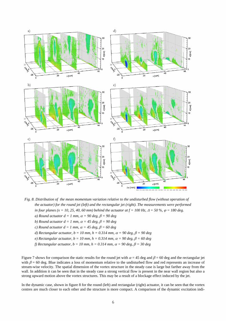
In the dynamic case, shown in figure 8 for the round (left) and rectangular (right) actuator, it can be seen that the vortex centres are much closer to each other and the structure is more compact. A comparison of the dynamic excitation indi-
a) d)
c)
b) e)
f)
Fig. 8. Distribution of the mean momentum variation relative to the undisturbed flow (without operation of the actuator) for the round jet (left) and the rectangular jet (right). The measurements were performed in four planes (x = 10, 25, 40, 60 mm) behind the actuator at f = 100 Hz, ∆ = 50 %, ϕ = 180 deg. a) Round actuator d = 1 mm, α = 90 deg, β = 90 deg b) Round actuator d = 1 mm, α = 45 deg, β = 90 deg c) Round actuator d = 1 mm, α = 45 deg, β = 60 deg d) Rectangular actuator, b = 10 mm, h = 0.314 mm, α = 90 deg, β = 90 deg e) Rectangular actuator, b = 10 mm, h = 0.314 mm, α = 90 deg, β = 60 deg f) Rectangular actuator, b = 10 mm, h = 0.314 mm, α = 90 deg, β = 30 deg
7
cates that in any state of the dynamic process the up-wash flow is as massive as in the steady case. The increasing and decreasing of the dominance of the induced vortex structures are conducted by a chang-ing blockage effect.
The sequence of results displayed in figure 8 a-c) reveals for a fixed phase angle of ϕ = 180 deg the distribution of the mean momentum variation relative to the natural flow without operation of the actuator. The upper result was measured behind the actuator with the round orifice. The orientation of the jet axis was parallel to the z direction which is normal to the wall. In case of the centre result the jet axis was in the yz plane (stream-wise wall-normal) with α = 45 deg and in the lower result the axis has a steam-wise ve-locity component against the main flow direction in addition with α = 45 deg and β = 60 deg. It can be seen clearly that without a span-wise jet component no high momentum fluid is transferred in the near wall region. However, when the jet axis is rotated around the z axis the flow around the jet becomes asymmetric and high momentum fluid from the outer region of the boundary layer is transferred indirectly towards the wall. This result indicates nicely the sen-sitivity of the actuator performance on the control parameter.
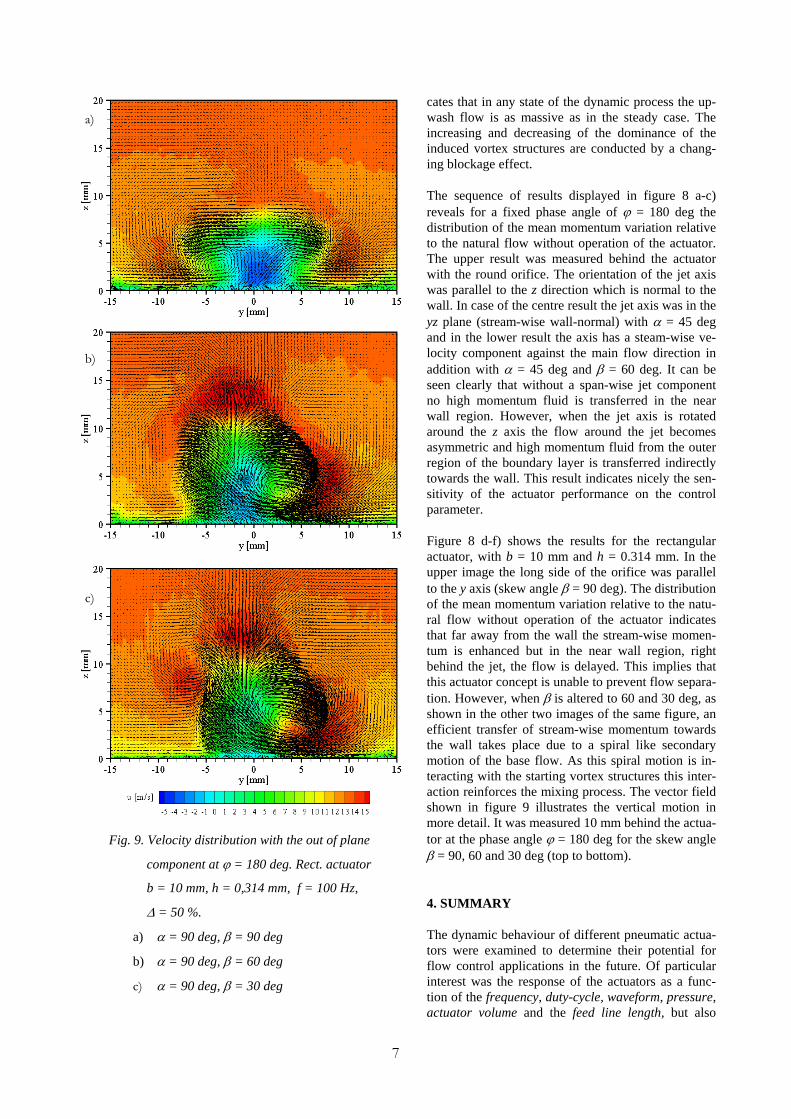
Figure 8 d-f) shows the results for the rectangular actuator, with b = 10 mm and h = 0.314 mm. In the upper image the long side of the orifice was parallel to the y axis (skew angle β = 90 deg). The distribution of the mean momentum variation relative to the natu-ral flow without operation of the actuator indicates that far away from the wall the stream-wise momen-tum is enhanced but in the near wall region, right behind the jet, the flow is delayed. This implies that this actuator concept is unable to prevent flow separa-tion. However, when β is altered to 60 and 30 deg, as shown in the other two images of the same figure, an efficient transfer of stream-wise momentum towards the wall takes place due to a spiral like secondary motion of the base flow. As this spiral motion is in-teracting with the starting vortex structures this inter-action reinforces the mixing process. The vector field shown in figure 9 illustrates the vertical motion in more detail. It was measured 10 mm behind the actua-tor at the phase angle ϕ = 180 deg for the skew angle β = 90, 60 and 30 deg (top to bottom).
4. SUMMARY
The dynamic behaviour of different pneumatic actua-tors were examined to determine their potential for flow control applications in the future. Of particular interest was the response of the actuators as a func-tion of the frequency, duty-cycle, waveform, pressure, actuator volume and the feed line length, but also
Fig. 9. Velocity distribution with the out of plane
component at ϕ = 180 deg. Rect. actuator
b = 10 mm, h = 0,314 mm, f = 100 Hz,
∆ = 50 %.
a) α = 90 deg, β = 90 deg
b) α = 90 deg, β = 60 deg
c) α = 90 deg, β = 30 deg
a)
b)
c)
8
effects of the geometrical properties of the different actuators were examined. However, due to the strong velocity variations and the small area of the actuator outlets only the far field structure of the jet could be investigated. The in-vestigation indicates that the skewed jet becomes most efficient when the jet axis is not aligned with the main flow di-rection, because in this case a strong large scale secondary flow is generated that transfers high momentum fluid in the near wall region. Blowing with a strong tangential component, on the other hand, seems to be less efficient, relative to the oblique one, because of two reasons. First, no spiral motion of the base flow is induced due to the symmetry. Sec-ond, the decrease of the jet velocity is to strong for an efficient momentum transfer in the near wall region. In case of the rectangular actuator it could be demonstrated that the efficiency decreases when the orientation of the actuator be-comes perpendicular to the main flow direction, because in this case no asymmetric large scale vortex structure is gen-erated that transfers high momentum fluid from the outer region of the boundary layer towards the wall. Finally, it could be shown that the momentum pattern of the dynamic jet becomes very similar to the static one shortly after open-ing the valve. However, during the opening and closing of the valve, a strong span-wise modulation of the base flow can be observed that stimulates the mixing.
REFERENCES Chang P. K. (1976). “Control of Flow Separation.” Hemisphere Publishing Corporation, McGraw-Hill Book Company. Compton, D. A. and Johnston, J. P. (1992). “Streamwise Vortex Production by Pitched and Skewed Jets in a Turbulent Boundary Layer.” AIAA Journal, Vol. 30, No. 3, pp. 640-647. Gad-el-Hak, M. (2001). “Flow Control: The Future.” Journal of Aircraft, Vol. 38, No. 3, pp. 402-418. Johari, H. and Rixon, G. S. (2003). “Effects of Pulsing on the Vortex Generator Jet.” AIAA Journal, Vol. 41, No. 12, pp. 2309-2315. Johari, H., Pacheco-Tougas M. and Hermanson, J. C. (1999). “Penetration and Mixing of Fully Modulated Turbulent Jets in Crossflow.” AIAA Journal, Vol. 37, No. 7, pp. 842-850. Johnston, J. P. and Nishi, M. (1990). “Vortex Generator Jets – Means for Flow Separation Control.” AIAA Journal, Vol. 26, No. 6, pp. 989-994. Kähler, C.J. and Scholz, U. (2003). „Investigation of laser-induced flow structures with time-resolved PIV, BOS and IR technology.” 5th International Symposium on Particle Image Velocimety, Busan, Korea, September 22-24, Paper 3223. McManus, K., Ducharme, A., Goldey, C. and Magill, J. (1996). “Pulsed Jet Actuators for Suppressing Flow Separa-tion.” AIAA Paper 96-0442. McManus, K. R., Joshi, P. B., Legner, H. H. and Davis S. J. (1995). “Active Control of Aerodynamic Stall using Pulsed Jet Actuators.” AIAA Paper 95-2187. Nagib, H., Kiedaisch, J., Greenblatt D., Wygnanski, I. and Hassan, A. (2001). „Effective Flow Control for Rotorcraft Applications at Flight Mach Number.“ AIAA Paper 2001-2974.