
Investigation of thermal and fluidic losses and their ...
11
Investigation of thermal and fluidic losses and their effect on the performances of a Stirling refrigerator Influence des pertes thermiques et fluidiques sur les performances d’un réfrigérateur Stirling Résumé Muluken Z. Getie 1,2,3,* , Francois LANZETTA 1 , Sylvie BEGOT 1 , Bimrew T. ADMASSU 3 1 FEMTO-ST Institute, Univ. Bourgogne Franche-Comté,CNRS Parc technologique, 2 avenue Jean Moulin, F-90000 Belfort, France. 2 Bahir Dar Energy Center, Bahir Dar Institute of Technology, Bahir Dar University, Bahir Dar, Ethiopia. 3 Faculty of Mechanical and Industrial Engineering, Bahir Dar Institute of Technology, Bahir Dar University, Bahir Dar, Ethiopia. * (Corresponding author : [email protected]) RÉSUMÉ. La conception d’une machine Stirling nécessite la compréhension des processus qui régissent leur fonction- nement pour prédire les paramètres de fonctionnement optimaux de la machine. Le modèle simple modifié utilisant les paramètres géométriques du modèle de moteur FEMTO-ST est appliqué dans cet article pour étudier l’influence des pertes en fonction de la fréquence de fonctionnement et de la pression de charge. Les variations des pertes de charge dans le régénérateur et les échangeurs de chaleur ont été étudiées en fonction de la fréquence de fonctionnement et de la pression de charge. La part des différentes pertes de puissances thermiques ainsi que leurs effets sur les performances de refroidissement ont été évalués aux différentes fréquences de fonctionnement et pressions de charge. Les pertes par frottement des fluides et les pertes dues aux imperfections du régénérateur augmentent avec la vitesse de rotation et la pression de charge. ABSTRACT. The design of a Stirling machine requires the understanding of the processes that govern their operation to predict the optimum operating parameters of the machine. The modified simple model using the geometrical parameters of the FEMTO-ST engine model is applied in this paper to investigate the trend of losses with respect to operating fre- quency and charging pressure. The variation of pressure drops across the regenerator and heat exchangers have been investigated as functions of operating frequency and charging pressure in order to predict the extent of fluid friction losses. The share of different power and heat losses as well as their effects on cooling performance have been evaluated at the different operating frequencies and charging pressures. The share of fluid friction loss and loss due to regenerator imperfection increase with rotational speed and charging pressure. MOTS-CLÉS. Réfrigérateur Stirling, Pertes de charge, Pertes de puissance, Performances, Régénérateur. KEYWORDS. Stirling refrigerator, pressure drop, Power losses, Heat losses, Performance, Share of losses. Nomenclature c 2017 ISTE OpenScience – Published by ISTE Ltd. London, UK – openscience.fr Page | 1
Transcript of Investigation of thermal and fluidic losses and their ...

Investigation of thermal and fluidic losses and theireffect on the performances of a Stirling refrigerator
Influence des pertes thermiques et fluidiques sur les performancesd’un réfrigérateur Stirling Résumé
Muluken Z. Getie1,2,3,*, Francois LANZETTA1, Sylvie BEGOT1, Bimrew T. ADMASSU3
1 FEMTO-ST Institute, Univ. Bourgogne Franche-Comté,CNRS Parc technologique, 2 avenue Jean Moulin, F-90000 Belfort, France.2 Bahir Dar Energy Center, Bahir Dar Institute of Technology, Bahir Dar University, Bahir Dar, Ethiopia.3 Faculty of Mechanical and Industrial Engineering, Bahir Dar Institute of Technology, Bahir Dar University, Bahir Dar, Ethiopia.*(Corresponding author : [email protected])
RÉSUMÉ. La conception d’une machine Stirling nécessite la compréhension des processus qui régissent leur fonction-nement pour prédire les paramètres de fonctionnement optimaux de la machine. Le modèle simple modifié utilisant lesparamètres géométriques du modèle de moteur FEMTO-ST est appliqué dans cet article pour étudier l’influence despertes en fonction de la fréquence de fonctionnement et de la pression de charge. Les variations des pertes de chargedans le régénérateur et les échangeurs de chaleur ont été étudiées en fonction de la fréquence de fonctionnement et de lapression de charge. La part des différentes pertes de puissances thermiques ainsi que leurs effets sur les performancesde refroidissement ont été évalués aux différentes fréquences de fonctionnement et pressions de charge. Les pertes parfrottement des fluides et les pertes dues aux imperfections du régénérateur augmentent avec la vitesse de rotation et lapression de charge.ABSTRACT. The design of a Stirling machine requires the understanding of the processes that govern their operation topredict the optimum operating parameters of the machine. The modified simple model using the geometrical parametersof the FEMTO-ST engine model is applied in this paper to investigate the trend of losses with respect to operating fre-quency and charging pressure. The variation of pressure drops across the regenerator and heat exchangers have beeninvestigated as functions of operating frequency and charging pressure in order to predict the extent of fluid friction losses.The share of different power and heat losses as well as their effects on cooling performance have been evaluated atthe different operating frequencies and charging pressures. The share of fluid friction loss and loss due to regeneratorimperfection increase with rotational speed and charging pressure.MOTS-CLÉS. Réfrigérateur Stirling, Pertes de charge, Pertes de puissance, Performances, Régénérateur.KEYWORDS. Stirling refrigerator, pressure drop, Power losses, Heat losses, Performance, Share of losses.
Nomenclature
c© 2017 ISTE OpenScience – Published by ISTE Ltd. London, UK – openscience.fr Page | 1

A cross sectional area, m2
Awg wetted area of the metal, m2
C average molecular speed, m.s−1
Cp isobaric specific heat, J.kg−1.K−1
Cv isochoric specific heat, J.kg−1.K−1
D piston diameter, m
d hydraulic diameter, m
fr Reynolds friction factor
G mass flux, kg.m−2.s−1
J annular gap between the cylinder andpiston displacer, m
K heat conductivity, W.m−1.K−1
L length, m
m mass of working fluid, kg
mleak mass leakage , kg
n rotational speed, rpm
NTU number of transfer unit
Nst Stanton number
Q heat, m
P pressure, Pa
Pr Prandtl number
R gas constant, J.kg−1.K−1
Re Reynolds number
s stroke , m
T temperature, K
V volume, m3
Wi,ad ideal adiabatic work, m
Greek symbols
∆ difference
ε regenerator effectiveness
γ ratio of specific heats, (Cp/Cv)
ω angular speed, rad.s−1
τ compression ratio
θ crank angle, rad
Index and exponent
c compression space
cr chiller
e expansion space
g gas
h hot heat exchanger
r regenerator
c© 2017 ISTE OpenScience – Published by ISTE Ltd. London, UK – openscience.fr Page | 2
1. Introduction
The Stirling engine is one of a variety of external heat engines that can be used to generate power fromvarious thermal energy sources. First, it was invented in 1816 by Robert Stirling. However, the benefitsof Stirling engines have been revealed with the advancements in engineering and the demonstrationof new methods to implement this thermodynamic cycle. It could be used in the reverse cycle as theStirling refrigerator as it was first realized as a cooling machine in 1832 [1]. Due to these facts, Stirlingmachines are suitable alternatives for power generation and refrigeration in various applications. TheStirling cycle refrigerating machine designs are categorized as kinematic machines, where the piston anddisplacer are mechanically linked to the drive shaft, or free-piston machines, where the piston is coupledto the power supply by a linear motor and the displacer is driven by the gas pressure variation in thesystem. Appropriate design and modeling of Stirling machines will result in better performance as it willminimize irreversibilities associated with the operation and geometrical configuration.
The impact of losses has been investigated on the performance of irreversible solar-powered Gammatype Stirling engine [2]. They highlighted that the two main dissipations are regenerator imperfectionloss and leakage loss in the engine. These losses are mostly dependent on geometrical and operationalparameters. A combination of geometric and operating parameters was optimized for the Beta-type Stir-ling engine by Ahmed et al. [3]. In the research, it has been discussed that almost all losses increase withoperating speed and charging pressure. However, the share of each loss have not been discussed.
Theoretical analysis and optimization of geometrical parameters for Stirling engines have been conduc-ted [4]. In this research, it has been reported that alpha-type Stirling engines are less applicable forlow-temperature difference, whereas Beta-type engine produced the highest shaft work.
A comprehensive review of the Stirling cooling machines has been conducted for a range of coolingapplications [5]. The review have presented the general working principle, the configuration and drivemechanisms as well as research findings of Stirling refrigerators. Due to its wider application, hightheoretical COP, as well as quieter and simpler operation, Stirling cycle cooler is worth researching.Different thermodynamic models for predicting the performance of the Stirling cooler were also proposedand developed in the past decades.
A Stirling refrigerator with a V-type configuration was approximated for a domestic cooling devicewith a charging pressure of 2 bar and compression ratio ranging between 1.5 and 2 [6]. The refrigeratorperformance parameters COP and cooling power showed a parabolic shape with a single optimal perfor-mance value with respect to operating speed [7]. Eid et al. [8] also investigate the effect of operatingspeed and they confirmed that cooling power has a single optimum value with respect to speed. It hasbeen presented that, if engine speed increases too much, cycle efficiency will decrease as a result of therapid increase in flow resistance and regenerator heat transfer losses [9].
The effects of rotational speed and charged pressure on different types of losses have been investigatedfor a Stirling engine [3, 9, 10]. All types of losses have been increased with an increase in operating speedas well as with charge pressure [3]. Heat conduction, shuttle heat, and flow resistance losses changedslightly as charged pressure increased [9]. Pressure drop loss, mechanical friction loss, and buffer spacelosses increased with rotational speed [10].
Due to losses associated with real-world conditions compared with ideal situations used for analytical
c© 2017 ISTE OpenScience – Published by ISTE Ltd. London, UK – openscience.fr Page | 3

purposes, a practical Stirling refrigerator can’t achieve a performance of the Carnot limit. A non-idealsecond-order numerical model with losses has been developed for domestic Stirling refrigerator [11].However, the effect and trend of each loss on the performance have not been investigated so far in detailfor the Stirling cycle refrigerator. This research tries to analyze the share of different types of losses withrespective categories and their effect on the overall performance of the Stirling cycle refrigerator.
The purpose of this paper is to analyze the percentage share of different losses and to investigate theeffects of these losses on engine performance. Actually, this paper has been also presented to the nationalthermal conference [13].
2. Theory
The Stirling cycle machine consists of two variable volumes (compression and expansion) spaces phy-sically separated by a regenerator and three constant volumes. For the Stirling cycle refrigerator, heat isabsorbed from the low-temperature heat source, part of the heat is stored and released in the regenerator,and rejected to a hot heat sink (see Fig 1).
Figure 1.: Schematic diagram of Stirling refrigerator.
The four thermodynamic transformations for an ideal reversed Stirling cycle includes :
1. An isothermal compression where heat is rejected to the heat sink (hot heat exchanger).
2. Isochoric cooling where the gas transmits heat to the regenerator.
3. An isothermal expansion where heat is absorbed from the cold source (chiller).
4. Isochoric heating where the heat stored in the regenerator is transmitted to the working fluid.
A non-ideal numerical model has been developed in the author’s previous article [11]. In such a ther-modynamic model, the overall Stirling refrigeration machine is configured into five control volumes(two working spaces and three heat exchangers) serially connected similar to works of Urieli and Ber-chowitz [12]. The overall approach for driving the equation set that could represent for the analysis ofsuch type of machine is to apply energy conservation equation and equation of state for each controlvolume and link with the equation of conservation of mass across the whole refrigerating machine. In
c© 2017 ISTE OpenScience – Published by ISTE Ltd. London, UK – openscience.fr Page | 4

this paper, such a model is used to evaluate the share of different losses and their effect on the coolingperformance of the Stirling refrigerator.
2.1. Numerical model
The performance of Stirling machine is strongly dependent on geometrical and physical parameterssuch as dimensions, heat transfer coefficients, heat source temperatures and regenerator characteristics.Predicting the performance of Stirling machine is important for the design of the machine. The idealStirling cycle has been already studied by several researchers ; however the performance of real Stirlingmachine is far from the ideal Stirling cycle.
The system of ideal adiabatic differential equations was modified as described by author’s previouswork [11] through including the effects of gas leakage from working space to buffer space (crankcase)and shuttle heat loss by displacer from compression to expansion spaces for the Stirling cycle refrigera-ting machine. The summary of modified ideal adiabatic equation is presented as shown in Table 1. Thederivative operator D based on [12] with respect to time where (DX = dX
dt ) and X is a thermodynamicparameter (P, V, T, W, Q, m).
Parameters equations
Pressure DP =−Pγ(DVcTch
+DVeTcre
)+γRDQshutCp
(Tch−TcreTchTcre
)−2γRDmleak
VcTch
+γ(VhTh
+VrTr
+VcrTcr
)+ VeTcre
Change of mass Dmi = miDPP = DP
RViTi
(wherei = h, r, cr)
Dmc =PDVc+
VcDPγ
RTch+ DQshut
CpTch
Dme =PDVe+
VeDPγ
RTcre− DQshut
CpTcre
DQshut =πs2KgDd
8JLd(Tc − Te)
Mass flow mch = −Dmc − DQshutCpTch
−Dmleak
mhr = mch −Dmh , mrcr = mcre +Dmcr
mcre = Dme − DQshutCpTcre
Where, Dmleak = dpπP+Pbuffer
4RTg(UpJ − J3
6µ (P−Pbuffer
Lp))
Temperature variation DTe = Te(DPP + DVe
Ve− Dme
me)
DTc = Tc(DPP + DVc
Vc− Dmc
mc)
DQh,i = VhDPCvR − Cp(Tchmch − Thmhr)
DQr,i = VrDPCvR − Cp(Thmhr − Tcrmrcr)
Energy and power DQcr,i = VcrDPCvR − Cp(Tcrmrcr − Tcremcre)
DWi,ad = DWc +DWe where
DWc = PdVc and DWe = PDVe
Table 2.1.: Summary of modified ideal adiabatic model (adapted from [11]).
Then, the model was further corrected to modified simple model by including power and heat losses.These losses include regenerator imperfection loss, fluid friction loss, mechanical friction, conductionheat loss in the regenerator wall, pressure drop due to finite speed of piston, conduction heat loss, and
c© 2017 ISTE OpenScience – Published by ISTE Ltd. London, UK – openscience.fr Page | 5
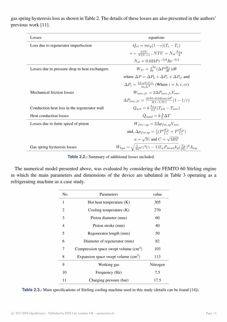
gas spring hysteresis loss as shown in Table 2. The details of these losses are also presented in the authors’previous work [11].
Losses equations
Loss due to regenerator imperfection Qrl = mcp(1− ε)(Tc − Te)
ε = NTUNTU+1 , NTU = Nst
AwgA
Nst = 0.023Pr−0.6Re−0.2
Losses due to pressure drop in heat exchangers Wfr =∫ 2π0 (∆P dVe
dθ )dθ
where ∆P = ∆Ph + ∆Pr + ∆Pcr and
∆Pi = 2frµViGilimidi
2 (Where i = h, r, cr)
Mechanical friction losses Wmec.fr = 2∆Pmec.frVswc
∆Pmec.fr = (0.94+0.045sn)105
3(1−1/3τ) (1− 1/τ)
Conduction heat loss in the regenerator wall Qwrl = kAwgLf (Twh − Twcr)
Heat conduction losses Qcond = kAL∆T
Losses due to finite speed of piston Wfin−sp = 2∆pfin.spVswc
and, ∆pfin.sp = 12(P
aUpCc
+ PaUpCe
)
a =√
3γ and C =√
3RT
Gas spring hysteresis losses Whys =√
132ωγ
3(γ − 1)TwPmeankg(Vd2Vt
)2Awg
Table 2.2.: Summary of additional losses included.
The numerical model presented above, was evaluated by considering the FEMTO 60 Stirling enginein which the main parameters and dimensions of the device are tabulated in Table 3 operating as arefrigerating machine as a case study.
No Parameters value
1 Hot heat temperature (K) 305
2 Cooling temperature (K) 270
3 Piston diameter (mm) 60
4 Piston stroke (mm) 40
5 Regenerator length (mm) 50
6 Diameter of regenerator (mm) 82
7 Compression space swept volume (cm3) 103
8 Expansion space swept volume (cm3) 113
9 Working gas Nitrogen
10 Frequency (Hz) 7.5
11 Charging pressure (bar) 17.5
Table 2.3.: Main specifications of Stirling cooling machine used in this study (details can be found [14]).
c© 2017 ISTE OpenScience – Published by ISTE Ltd. London, UK – openscience.fr Page | 6
3. Results and discussion
In this section, the shares of different types of losses associated with the Stirling cycle with the respec-tive category are presented. The variation of pressure drops across the regenerator and heat exchangershave been investigated as functions of operating frequency and charging pressure in order to predict theextent of fluid friction losses. Furthermore, the trends of these losses with operating speed are discussed.These results are based on simulation findings of the second-order numerical model described so farusing air as a working fluid.
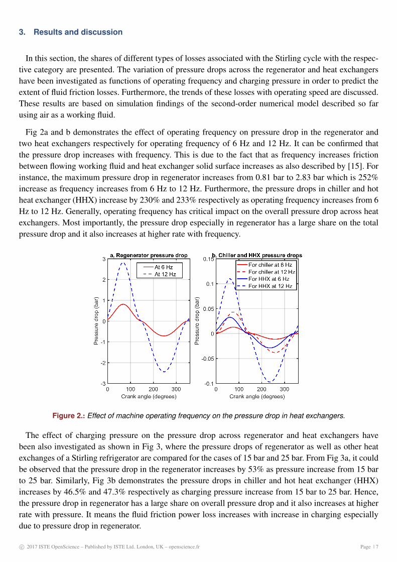
Fig 2a and b demonstrates the effect of operating frequency on pressure drop in the regenerator andtwo heat exchangers respectively for operating frequency of 6 Hz and 12 Hz. It can be confirmed thatthe pressure drop increases with frequency. This is due to the fact that as frequency increases frictionbetween flowing working fluid and heat exchanger solid surface increases as also described by [15]. Forinstance, the maximum pressure drop in regenerator increases from 0.81 bar to 2.83 bar which is 252%increase as frequency increases from 6 Hz to 12 Hz. Furthermore, the pressure drops in chiller and hotheat exchanger (HHX) increase by 230% and 233% respectively as operating frequency increases from 6Hz to 12 Hz. Generally, operating frequency has critical impact on the overall pressure drop across heatexchangers. Most importantly, the pressure drop especially in regenerator has a large share on the totalpressure drop and it also increases at higher rate with frequency.
Figure 2.: Effect of machine operating frequency on the pressure drop in heat exchangers.
The effect of charging pressure on the pressure drop across regenerator and heat exchangers havebeen also investigated as shown in Fig 3, where the pressure drops of regenerator as well as other heatexchanges of a Stirling refrigerator are compared for the cases of 15 bar and 25 bar. From Fig 3a, it couldbe observed that the pressure drop in the regenerator increases by 53% as pressure increase from 15 barto 25 bar. Similarly, Fig 3b demonstrates the pressure drops in chiller and hot heat exchanger (HHX)increases by 46.5% and 47.3% respectively as charging pressure increase from 15 bar to 25 bar. Hence,the pressure drop in regenerator has a large share on overall pressure drop and it also increases at higherrate with pressure. It means the fluid friction power loss increases with increase in charging especiallydue to pressure drop in regenerator.
c© 2017 ISTE OpenScience – Published by ISTE Ltd. London, UK – openscience.fr Page | 7
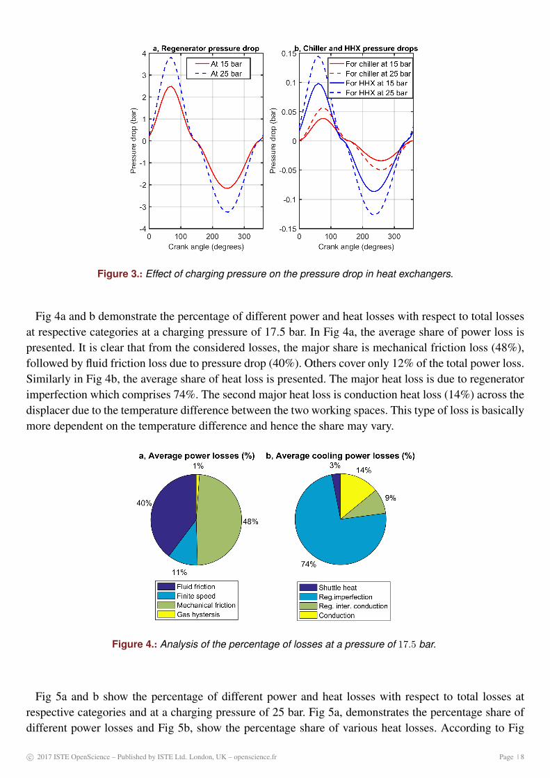
Figure 3.: Effect of charging pressure on the pressure drop in heat exchangers.
Fig 4a and b demonstrate the percentage of different power and heat losses with respect to total lossesat respective categories at a charging pressure of 17.5 bar. In Fig 4a, the average share of power loss ispresented. It is clear that from the considered losses, the major share is mechanical friction loss (48%),followed by fluid friction loss due to pressure drop (40%). Others cover only 12% of the total power loss.Similarly in Fig 4b, the average share of heat loss is presented. The major heat loss is due to regeneratorimperfection which comprises 74%. The second major heat loss is conduction heat loss (14%) across thedisplacer due to the temperature difference between the two working spaces. This type of loss is basicallymore dependent on the temperature difference and hence the share may vary.
Figure 4.: Analysis of the percentage of losses at a pressure of 17.5 bar.
Fig 5a and b show the percentage of different power and heat losses with respect to total losses atrespective categories and at a charging pressure of 25 bar. Fig 5a, demonstrates the percentage share ofdifferent power losses and Fig 5b, show the percentage share of various heat losses. According to Fig
c© 2017 ISTE OpenScience – Published by ISTE Ltd. London, UK – openscience.fr Page | 8

Figure 5.: Analysis of the percentage of losses at a pressure of 25 bar.
4, it is noticed that the percentage share of fluid friction loss and loss due to regenerator imperfectionincrease with increase charging pressure. Great care should be given to minimization of fluid friction lossand regenerator imperfection for machines operating at higher pressure.
Fig 6a,b,c, and d illustrate the effect of rotational speed on the major power losses, major heat powerlosses, cooling power, and COP respectively at an ambient temperature of 300 K, chiller temperature of270 K, and charging pressure of 17.5 bar. As demonstrated in Fig 6a, except for gas hysteresis powerloss all power losses are mainly affected by rotational speed. Fluid friction loss increases strongly at ahigher speed. As it is shown in Fig 6b regenerator imperfection loss linearly increases and all other heatpower losses relatively remain unchanged with the operating frequency. From Fig 6c, it could be seenthat cooling power loss increases with an increase in rotational speed. This is mainly due to the increasein the thermodynamic cycle per unit time. Lastly, as it is seen in Fig 6d, COP has an optimum value withan increase in rotational speed. This is expected as demonstrated in Fig 6a and b, both power and heatpower losses increase which resulted in lower COP at a higher speed.
4. Conclusion
The design and development of Stirling cycle refrigerators require an understanding of the processesthat govern the operation of the machine. The operating condition and processes of the Stirling cyclerefrigerator are accompanied by different types of losses. A non-ideal thermodynamic model is usedto investigate the share of different losses and the trend of such losses with the operating speed andcharging pressure. The variation of pressure drops across the regenerator and heat exchangers have beeninvestigated as functions of operating frequency and charging pressure in order to predict the extent offluid friction losses. The major power and heat losses, as well as their effect on the performance of thecooling machine, have been discussed. Fluid friction power losses and regenerator imperfection lossesare found as the two major losses that are mostly affected by charging pressure and operating speed.The shares of these two losses over their respective total losses increase with an increase in operating
c© 2017 ISTE OpenScience – Published by ISTE Ltd. London, UK – openscience.fr Page | 9

Figure 6.: Trend of major losses and refrigeration performance with respect to the operating frequency.
speed as well as with charging pressure. The coefficient of performance of the refrigerating machinedecreases at higher operating frequency primarily due to the increase of fluid friction and regeneratorimperfection losses. Hence, during the design of the Stirling refrigerator, critical investigation of lossesshall be conducted for the intended operating range of the machine to minimize major losses and thesummation of overall losses. Then, better performance could be achieved.
Bibliographie
[1]. J.W. Kohler, The Stirling refrigeration cycle in cryogenic technology, The advancement of science, 25 (1968) 161.
[2]. R. Li, L. Grosu, and D. Queiros-Condé, Losses effect on the performance of a Gamma type Stirling engine, EnergyConversion and Management, 114 (2016) 28-37.
[3]. F. Ahmed, H. Hulin, A. M. Khan, Numerical modeling and optimization of beta-type Stirling engine, Applied ThermalEngineering, 149 (2019) 385-400.
[4]. C. Cheng , H. Yang, Optimization of geometrical parameters for Stirling engines based on theoretical analysis, AppliedEnergy, 92 (2012) 395-405.
[5]. M. Z. Getie, F. Lanzetta, S Bégot, B. T. Admassu, A. A. Hassen, Reversed regenerative Stirling cycle machine forrefrigeration application : A review, International Journal of Refrigeration, 118 (2020) 173-187.
[6]. O.E. Ataer, H. Karabulut, Thermodynamic analysis of the V-type Stirling-cycle refrigerator, International Journal ofRefrigeration, 28 (2005) 183-189.
c© 2017 ISTE OpenScience – Published by ISTE Ltd. London, UK – openscience.fr Page | 10
[7]. H. Hachem, R. Gheith, F. Aloui, S. B. Nasrallah, Optimization of an air-filled Beta type Stirling refrigerator, Interna-tional Journal of Refrigeration, 76 (2017) 296-312.
[8]. E. I. Eid a, R. A. Khalaf-Allah, A. M. Soliman, A. S. Easa, Performance of a beta Stirling refrigerator with tubularevaporator and condenser having inserted twisted tapes and driven by a solar energy heat engine, Renewable Energy, 135(2019) 1314-1326.
[9]. M. Ni, B. Shi, G. Xiao , H. Peng, U. Sultan, S. Wang, Z. Luo, K. Cen, Improved Simple Analytical Model andexperimental study of a 100W β −type Stirling engine, Applied Energy, 169 (2016) 768-787.
[10]. K. Hirata, S. Iwamoto, F. Toda, K. Hamaguchi, Perfromance evaluation for a 100 W Stirling engine, Proceedings of8th International Stirling Engine Conference. (1997), 19-28.
[11]. M. Z. Getie, F. Lanzetta, S Bégot, B. T. Admassu, S. Djetel-gothe, A non-ideal second order thermal model witheffects of losses for simulating Beta-type Stirling refrigerating machine, International Journal of Refrigeration, (2021).https ://doi.org/10.1016/j.ijrefrig.2021.05.018.
[12]. I. Urieli, D.M. Berchowitz, Stirling Cycle Engine Analysis, Adam Hilger Ltd, Bristol(1984).
[13]. M. Z. Getie, F. Lanzetta, S Bégot, B. T. Admassu, Loss effect Analysis of irreversible Stirling cycle Refrigerator, 29econgrès Français de Thermique, (2021). https ://doi.org/10.25855/SFT2021-035.
[14]. S. Djetel, Modélisation et réalisation d’une machine réceptrice de Stirling pour la production de froid, Thèse del’Université Bourgogne Franche-Comté de Belfort, 2020.
[15]. I. Tlili,Y.Timoumi, S.B.,Nasrallah, Analysis and design consideration of mean temperature differential Stirling enginefor solar application, Renewable energy, 33(2008), 1911–1921
Acknowledgements
This work has been supported by EIPHI Graduate School (contract ANR- 17- EURE- 0002), RegionBourgogne-Franche-Comte, Bahir Dar Institute of Technology, the Embassy of France to Ethiopia andthen African Union, and the Ministry of Science and Higher Education of Ethiopia.
c© 2017 ISTE OpenScience – Published by ISTE Ltd. London, UK – openscience.fr Page | 11