iSTM mini...iSTM mini 1 Identifikation BAL.0523.0 • 2019-10-17 DE - 3 1 Identifikation Die...
108
T E C H N O L O G Y F O R T H E W E L D E R ´ S W O R L D . www.binzel-abicor.com DE Betriebsanleitung / EN Operating instructions ZH 使用说明 / JA 取扱説明書 iSTM mini DE Roboterhalterung EN Robot mount ZH 机器人固定装置 JA ロボットマウント
Transcript of iSTM mini...iSTM mini 1 Identifikation BAL.0523.0 • 2019-10-17 DE - 3 1 Identifikation Die...

T E C H N O L O G Y F O R T H E W E L D E R ´ S W O R L D .
w w w . b i n z e l - a b i c o r . c o m
DE Betriebsanleitung / EN Operating instructionsZH 使用说明 / JA 取扱説明書
iSTM miniDE RoboterhalterungEN Robot mountZH 机器人固定装置JA ロボットマウント

DE - 2 BAL.0523.0 • 2019-10-17
iSTM mini
DE Original Betriebsanleitung
© Der Hersteller behält sich das Recht vor, jederzeit und ohne vorherige Mitteilung Änderungen an dieser Betriebsanleitung durchzuführen, die durch Druckfehler, eventuelle Ungenauigkeiten der enthaltenen Informationen oder Verbesserung dieses Produktes erforderlich werden. Diese Änderungen werden jedoch in neuen Ausgaben berücksichtigt.
Alle in der Betriebsanleitung genannten Handelsmarken und Schutzmarken sind Eigentum der jeweiligen Besitzer/Hersteller.
Unsere aktuellen Produktdokumente, sowie alle Kontaktdaten der ABICOR BINZEL Ländervertretungen und Partner weltweit, finden Sie auf unserer Homepage www.binzel-abicor.com
1 Identifikation DE-31.1 Kennzeichnung DE-3
2 Sicherheit DE-32.1 Bestimmungsgemäße Verwendung DE-32.2 Pflichten des Betreibers DE-42.3 Persönliche Schutzausrüstung (PSA) DE-42.4 Klassifizierung der Warnhinweise DE-42.5 Angaben für den Notfall DE-4
3 Produktbeschreibung DE-53.1 Technische Daten DE-53.2 Abkürzungen DE-73.3 Typenschild DE-73.4 Verwendete Zeichen und Symbole DE-7
4 Lieferumfang DE-84.1 Transport DE-104.2 Lagerung DE-10
5 Funktionsbeschreibung DE-11
6 Inbetriebnahme DE-116.1 Transportieren und Aufstellen DE-116.2 Wartungsposition Roboter DE-126.2.1 iSTM mini am Roboter befestigen DE-136.2.2 Schlauchpaket am Roboter montieren DE-146.3 Brennerhals von ABIROB® G befestigen DE-176.4 Brennerhals ABIROB® W befestigen DE-186.5 Drahtführung montieren DE-196.5.1 Standardvariante DE-196.5.2 Variante Wire-Brake DE-206.5.3 Drahtführung kürzen DE-20
7 Betrieb DE-21
8 Außerbetriebnahme DE-21
9 Wartung und Reinigung DE-229.1 Wartungsintervalle DE-239.1.1 iSTM mini für ABIROB® G DE-239.1.2 iSTM mini für ABIROB® G mit Wire-Brake DE-249.1.3 iSTM mini für ABIROB® W DE-249.1.4 iSTM mini für ABIROB® W mit Wire-Brake DE-259.2 Drahtführung reinigen DE-25
10 Störungen und deren Behebung DE-25
11 Demontage DE-26
12 Entsorgung DE-2712.1 Werkstoffe DE-2712.2 Betriebsmittel DE-2712.3 Verpackungen DE-27

iSTM mini 1 Identifikation
BAL.0523.0 • 2019-10-17 DE - 3
1 IdentifikationDie Roboterhalterung iSTM mini, mit dem dazugehörigen Schlauchpaket, wird in der Industrie und im Gewerbe zur Verbindung zwischen Brennerhals und Roboter mit zentraler Mediendurchführung eingesetzt.Diese Betriebsanleitung beschreibt die Roboterhalterung iSTM mini in Verbindung mit dem Schweißbrennerhals ABIROB® W und dem Schweißbrennerhals ABIROB® G sowie die iSTM mini mit Wire-Brake in Verbindung mit dem Schweißbrennerhals ABIROB® W und ABIROB® G. Die iSTM mini darf nur mit Original ABICOR BINZEL Ersatzteilen betrieben werden.
1.1 KennzeichnungDie Roboterhalterung iSTM mini zusammen mit den in Abbildung 1 gezeigten Komponenten erfüllt die Anforderungen der einschlägigen EU-Richtlinien.
Das Produkt erfüllt die geltenden Anforderungen des jeweiligen Marktes für das Inverkehrbringen. Sofern es einer entsprechenden Kennzeichnung bedarf, ist diese am Produkt angebracht.
2 SicherheitBeachten Sie das beiliegende Dokument Sicherheitshinweise.
2.1 Bestimmungsgemäße Verwendung• Das in dieser Anleitung beschriebene Gerät darf ausschließlich zu dem in der Anleitung beschriebenen Zweck in der
beschriebenen Art und Weise verwendet werden. Beachten Sie dabei die Betriebs-, Wartungs- und lnstandhaltungsbedingungen.
• Jede andere Verwendung gilt als nicht bestimmungsgemäß.
• Eigenmächtige Umbauten oder Veränderungen zur Leistungssteigerung sind nicht zulässig.
1 Schweißbrenner ABIROB® G
2 Schutzkappe
3 Abdeckung4 iSTM mini
5 Schlauchpaket6 Schweißbrenner
ABIROB® W
7 Drahtklemmvorrichtung1
1nur bei Variante mit Wire BrakeAbb. 1 Übersicht
1 2 3 4 5
6
7

DE - 4 BAL.0523.0 • 2019-10-17
2 Sicherheit iSTM mini
2.2 Pflichten des Betreibers• Lassen Sie nur Personen am Gerät arbeiten, die
• mit den grundlegenden Vorschriften und Unfallverhütung vertraut sind;
• in der Handhabung des Geräts eingewiesen wurden;
• diese Bedienungsanleitung gelesen und verstanden haben;
• das beiliegende Dokument „Safety instructions“ gelesen und verstanden haben;
• entsprechend ausgebildet wurden;
• aufgrund ihrer fachlichen Ausbildung, Kenntnisse und Erfahrungen mögliche Gefahren erkennen können.
• Halten Sie andere Personen vom Arbeitsbereich fern.
• Beachten Sie die Arbeitssicherheitsvorschriften des jeweiligen Landes.
• Beachten Sie die Vorschriften zur Arbeitssicherheit und zur Unfallverhütung.
2.3 Persönliche Schutzausrüstung (PSA)Um Gefahren für den Nutzer zu vermeiden wird in dieser Anleitung das Tragen von persönlicher Schutzausrüstung (PSA) empfohlen.
• Sie besteht aus Schutzanzug, Schutzbrille, Atemschutzmaske Klasse P3, Schutzhandschuhen und Sicherheitsschuhen.
2.4 Klassifizierung der WarnhinweiseDie in der Betriebsanleitung verwendeten Warnhinweise sind in vier verschiedene Ebenen unterteilt und werden vor potenziell gefährlichen Arbeitsschritten angegeben. Geordnet nach abnehmender Wichtigkeit bedeuten sie Folgendes:
2.5 Angaben für den NotfallUnterbrechen Sie im Notfall sofort folgende Versorgungen:
• Elektrische Energieversorgung
• Druckluftzufuhr
• Gaszufuhr
• Kühlmittelzufuhr
Weitere Maßnahmen entnehmen Sie der Betriebsanleitung der Stromquelle oder der Dokumentation weiterer Peripheriegeräte.
GEFAHRBezeichnet eine unmittelbar drohende Gefahr. Wenn sie nicht gemieden wird, sind Tod oder schwerste Verletzungen die Folge.
WARNUNGBezeichnet eine möglicherweise gefährliche Situation. Wenn sie nicht gemieden wird, können schwere Verletzungen die Folge sein.
VORSICHTBezeichnet eine möglicherweise schädliche Situation. Wenn sie nicht gemieden wird, können leichte oder geringfügige Verletzungen die Folge sein.
HINWEIS
Bezeichnet die Gefahr, dass Arbeitsergebnisse beeinträchtigt werden oder Sachschäden an der Ausrüstung die Folge sein können.
iSTM mini 3 Produktbeschreibung
BAL.0523.0 • 2019-10-17 DE - 5
3 Produktbeschreibung
3.1 Technische Daten
WARNUNGGefahren durch nicht bestimmungsgemäße VerwendungBei nicht bestimmungsgemäßer Verwendung können vom Gerät Gefahren für Personen, Tiere und Sachwerte ausgehen.• Verwenden Sie das Gerät ausschließlich bestimmungsgemäß.• Bauen Sie das Gerät nicht eigenmächtig zur Leistungssteigerung um und verändern
Sie es nicht.• Jegliche Arbeiten am Gerät bzw. System sind ausschließlich befähigten Personen vorbehalten.
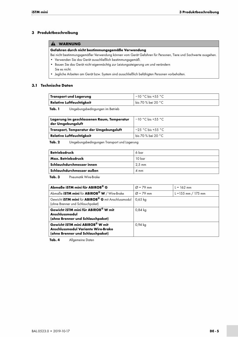
Transport und Lagerung −10 °C bis +55 °C
Relative Luftfeuchtigkeit bis 70 % bei 20 °C
Tab. 1 Umgebungsbedingungen im Betrieb
Lagerung im geschlossenen Raum, Temperatur der Umgebungsluft
−10 °C bis +55 °C
Transport, Temperatur der Umgebungsluft −25 °C bis +55 °C
Relative Luftfeuchtigkeit bis 70 % bei 20 °C
Tab. 2 Umgebungsbedingungen Transport und Lagerung
Betriebsdruck 6 bar
Max. Betriebsdruck 10 bar
Schlauchdurchmesser innen 2,5 mm
Schlauchdurchmesser außen 4 mm
Tab. 3 Pneumatik Wire-Brake
Abmaße iSTM mini für ABIROB® G Ø = 79 mm L = 162 mm
Abmaße iSTM mini für ABIROB® W / Wire-Brake Ø = 79 mm L =155 mm / 175 mm
Gewicht iSTM mini für ABIROB® G mit Anschlussmodul(ohne Brenner und Schlauchpaket)
0,65 kg
Gewicht iSTM mini für ABIROB® W mit Anschlussmodul(ohne Brenner und Schlauchpaket)
0,84 kg
Gewicht iSTM mini ABIROB® W mit Anschlussmodul Variante Wire-Brake(ohne Brenner und Schlauchpaket)
0,94 kg
Tab. 4 Allgemeine Daten

DE - 6 BAL.0523.0 • 2019-10-17
3 Produktbeschreibung iSTM mini
Die Belastungsdaten wurden unter normalen Bedingungen, bei geringer bis mittlerer Rückstrahlwärme, freier Luftzirkulation und ca. 28 °C Umgebungstemperatur ermittelt. Im Einsatz unter erschwerten Bedingungen sind die Belastungsdaten um 10–20% zu reduzieren.
A4 = Torsion max. ±155° A5 =Biegung max. +90°/−135° A6 = Torsion max. ±200°
Abb. 2 Maximale Belastung Schlauchpaket
HINWEIS
• Torsion A4 und A6 max. ± 355°• Zur korrekten Befestigung von iSTM mini und Schlauchpaket müssen Sie die 4. und 5. Achse des Roboters wie folgt
einstellen: 4. Achse = neutrale Stellung, 5. Achse = 10° geneigt, 6. Achse = neutrale Stellung
ABIROB® G ABIROB® W
Spannungsart DC
Polung der Elektroden in der Regel positiv
Drahtarten handelsübliche Runddrähte
Führungsart maschinengeführt
Spannungsbemessung 141 V Scheitelwert
Schutzart der maschinenseitigen Anschlüsse (EN 60529)
IP3X
Schutzgas (EN ISO 14175) CO2 und M21
Tab. 5 Allgemeine Brennerdaten nach EN 60974-7
Typ Kühlart Belastung1
1Die Belastungsdaten reduzieren sich bei Impulslichtbogen bis zu 35%
ED Draht-ø Gas-durchfluss
Angaben zur Kühlung
Kühl-leistung
Durch-fluss
Fließdruck
CO2 M21 min. min. min. max.
ABIROB® A A % mm l/min W l/min bar bar
G350 luft 350 300 100 0,8–1,2 ca. 20 800 ca. 20 / /
G360 luft 360 290 100 0,8–1,6 ca. 20 800 ca. 20 / /
G500 luft 500 400 100 0,8–1,6 ca. 20 800 ca. 20 / /
W300 flüssig 330 300 100 0,8–1,2 ca. 20 800 1,25 1,5 3,5
W500 flüssig 550 500 100 0,8–1,6 ca. 20 800 1,25 1,5 3,5
W600 flüssig 600 100 100 0,8–1,6 ca. 20 800 1,25 1,5 3,5
Tab. 6 Produktspezifische Brennerdaten (EN 60974-7) in Verbindung mit iSTM mini
A4: ±155° A6: ±200°
A5: +90°/−135°

iSTM mini 3 Produktbeschreibung
BAL.0523.0 • 2019-10-17 DE - 7
3.2 Abkürzungen
3.3 TypenschildDie iSTM mini ist wie folgt gekennzeichnet:
Beachten Sie für alle Rückfragen folgende Angaben:
• Gerätetyp, Gerätenummer, Angabe der Werksbescheinigung
3.4 Verwendete Zeichen und SymboleIn der Betriebsanleitung werden folgende Zeichen und Symbole verwendet:
ABIROB® G Maschinengeführter Schweißbrenner luftgekühlt
ABIROB® W Maschinengeführter Schweißbrenner flüssiggekühlt
Tab. 7 Abkürzungen und Begriffserklärung
1 Schutzkappe2 Abdeckung
3 Artikelnummer4 Gerätetyp
Abb. 3 Typenschild
1 2 3
4
Symbol Beschreibung
• Aufzählungssymbol für Handlungsanweisungen und Aufzählungen
Querverweissymbol verweist auf detaillierte, ergänzende oder weiterführende Informationen
1 Handlungsschritt/e im Text, die der Reihenfolge nach durchzuführen sind

DE - 8 BAL.0523.0 • 2019-10-17
4 Lieferumfang iSTM mini
4 Lieferumfang
iSTM mini für ABIROB® G
*Größe und Anzahl der Zylinderschrauben sind abhängig vom Robotertyp.
iSTM mini für ABIROB® G mit Wire-Brake
1 Schutzkappe2 Abdeckung
3 Zylinderschraube M4 × 164 Anschlussmodul5 Senkschraube M3 × 5
6 Abdeckung vorne7 Zylinderschraube M3 × 68 Abdeckung hinten
9 iSTM mini10 Zylinderschraube M4 × 12
Abb. 4 Lieferumfang iSTM mini für ABIROB® G
• Roboterhalterung iSTM mini • 8 Zylinderschrauben M4 × 12*
• Schlauchpaket iSTM mini • 7 Zylinderschrauben M4 × 16
• Abdeckung hinten • 2 Zylinderschrauben M3 × 6
• Abdeckung vorne • 2 Senkschrauben M3 × 5
• Schutzkappe • Steckschlüssel SW11
• Abdeckung • Dichtfett Düsofix, silikonfrei, 10 g Dose
• Führungsspirale • Werksbescheinigung
• gerade Verschraubung • Betriebsanleitung
• Schutzgasschlauch Ø 6 mm
Tab. 8 Lieferumfang iSTM mini für ABIROB® G
1 2 3 4 5 6 7 8 9
10
1 Schutzkappe2 Abdeckung
3 Zylinderschraube M4 × 164 Anschlussmodul5 Senkschraube M3 × 5
6 Abdeckung vorne7 Zylinderschraube M3 × 68 Abdeckung hinten
9 iSTM mini10 Zylinderschraube M4 × 12
Abb. 5 Lieferumfang iSTM mini für ABIROB® G mit Wire-Brake
1 2 3 4 5 6 7 8
9

iSTM mini 4 Lieferumfang
BAL.0523.0 • 2019-10-17 DE - 9
*Größe und Anzahl der Zylinderschrauben sind abhängig vom Robotertyp.
iSTM mini für ABIROB® W
*Größe und Anzahl der Zylinderschrauben sind abhängig vom Robotertyp.
• Roboterhalterung iSTM mini • 8 Zylinderschrauben M4 × 12*
• Schlauchpaket iSTM mini • 7 Zylinderschrauben M4 × 16
• Abdeckung hinten • 2 Zylinderschrauben M3 × 6
• Abdeckung vorne • 2 Senkschrauben M3 × 5
• Schutzkappe • Steckschlüssel SW11
• Abdeckung • Dichtfett Düsofix, silikonfrei, 10 g Dose
• Führungsspirale • Werksbescheinigung
• gerade Verschraubung • Betriebsanleitung
• Schutzgasschlauch Ø 6 mm
Tab. 9 Lieferumfang iSTM mini für ABIROB® G mit Wire-Brake
1 Schutzkappe2 Abdeckung
3 Zylinderschraube M4 × 164 iCAT mini W CAl kpl.
5 iSTM mini6 Zylinderschraube M4 × 12
Abb. 6 Lieferumfang iSTM mini für ABIROB® W
• Roboterhalterung iSTM mini • 8 Zylinderschrauben M4 × 12*
• Schlauchpaket iSTM mini W • 7 Zylinderschrauben M4 × 16
• Abdeckung • Dichtfett Düsofix, silikonfrei, 10 g Dose
• Schutzkappe • Werksbescheinigung
• Führungsspirale • Betriebsanleitung
Tab. 10 Lieferumfang iSTM mini für ABIROB® W
1 2 3 4 5 6

DE - 10 BAL.0523.0 • 2019-10-17
4 Lieferumfang iSTM mini
iSTM mini für ABIROB® W mit Wire-Brake
*Größe und Anzahl der Zylinderschrauben sind abhängig vom Robotertyp.
Ausrüst- und Verschleißteile separat bestellen. Bestelldaten und Identnummern der Ausrüst- und Verschleißteile, entnehmen Sie den aktuellen Bestellunterlagen. Kontakt für Beratung und Bestellung finden Sie im Internet unter www.binzel-abicor.com.
4.1 TransportDer Lieferumfang wird vor dem Versand sorgfältig geprüft und verpackt, jedoch sind Beschädigungen während des Transportes nicht auszuschließen.
4.2 LagerungPhysikalische Bedingungen der Lagerung im geschlossenen Raum:
3.1 Technische Daten auf Seite DE-5
1 Schutzkappe2 Abdeckung3 Zylinderschraube M4 × 16
4 iCAT / iSTM mini W CAl kpl.5 iSTM mini6 Zylinderschraube M4 × 12
7 Drahtklemmvorrichtung
Abb. 7 Lieferumfang iSTM mini für ABIROB® W mit Wire-Brake
• Roboterhalterung iSTM mini • 8 Zylinderschrauben M4 × 12*
• Schlauchpaket iSTM mini W • 7 Zylinderschrauben M4 × 16
• Abdeckung • Dichtfett Düsofix, silikonfrei, 10 g Dose
• Schutzkappe • Werksbescheinigung
• Führungsspirale • Betriebsanleitung
• Drahtklemmvorrichtung
Tab. 11 Lieferumfang iSTM mini für ABIROB® W mit Wire-Brake
1 2 3 4 5 6
7
Eingangskontrolle Kontrollieren Sie die Vollständigkeit anhand des Lieferscheins!Überprüfen Sie die Lieferung auf Beschädigung (Sichtprüfung)!
Bei Beanstandungen Ist die Lieferung beim Transport beschädigt worden, setzen Sie sich sofort mit dem letzten Spediteur in Verbindung! Bewahren Sie die Verpackung auf zur eventuellen Überprüfung durch den Spediteur.
Verpackung für den Rückversand
Verwenden Sie nach Möglichkeit die Originalverpackung und das Originalverpackungsmaterial. Bei auftretenden Fragen zur Verpackung und Transportsicherung nehmen Sie bitte Rücksprache mit Ihrem Lieferanten.
Tab. 12 Transport

iSTM mini 5 Funktionsbeschreibung
BAL.0523.0 • 2019-10-17 DE - 11
5 FunktionsbeschreibungDie Roboterhalterung iSTM mini dient zur positionsgenauen Aufnahme von Schweißbrennern. Sie wird mit Zylinderschrauben am Roboter befestigt.
6 Inbetriebnahme
6.1 Transportieren und Aufstellen
GEFAHRVerletzungsgefahr durch unerwarteten AnlaufFür die gesamte Dauer von Wartungs-, Instandhaltungs-, Montage- bzw. Demontage- und Reparaturarbeiten ist Folgendes zu beachten:• Schalten Sie die Stromquelle aus.• Sperren Sie die Gaszufuhr ab.• Sperren Sie die Kühlmittelzufuhr ab.• Sperren Sie die Druckluftzufuhr ab.• Trennen Sie alle elektrischen Verbindungen.• Schalten Sie die gesamte Schweißanlage aus.
HINWEIS
• Beachten Sie folgende Angaben:
3 Produktbeschreibung auf Seite DE-5
GEFAHRStromschlagGefährliche Spannung durch fehlerhafte Kabel.• Überprüfen Sie alle spannungsführenden Kabel und Verbindungen auf ordnungsgemäße Installation und
Beschädigungen.• Tauschen Sie schadhafte, deformierte oder verschlissene Teile aus.• Montieren Sie alle Teile spannungsfrei.
VORSICHTVerletzungsgefahrKörperliche Schäden durch herunterfallende Geräte und Anbauteile.• Wählen Sie zum Auspacken einen geeignete Ort.• Vermeiden Sie ruckartiges Anheben und Absetzen.• Heben Sie die Komponenten nicht über Personen oder andere Geräte hinweg.• Transportieren Sie die Komponenten in aufrechter Position.• Montieren Sie das Gerät mit geeigneter Hilfe.• Bringen Sie den Roboter in eine geeignete Montageposition
6.2 Wartungsposition Roboter auf Seite DE-12
• Achten Sie auf einen sicheren Stand.• Tragen Sie Ihre persönliche Schutzausrüstung: Sicherheitsschuhe mit Stahlkappen, Schutzhandschuhe, Schutzhelm,
Gehörschutz.• Verweisen Sie unbeteiligte Personen aus dem Gefahrenbereich.• Beachten Sie das Gewicht der einzelnen Komponenten.
3.1 Technische Daten auf Seite DE-5

DE - 12 BAL.0523.0 • 2019-10-17
6 Inbetriebnahme iSTM mini
6.2 Wartungsposition Roboter
VORSICHTDurch- bzw. Einstich durch DrahtelektrodeAugenverletzung beim Anschließen der Pneumatikleitung.Für die Version mit Wire-Brake kann es bei undichter oder nicht richtig angeschlossener Leitung zu ausströmender Druckluft kommen wodurch Partikel ins Auge gelangen können.Zur Vermeidung halten Sie folgende Anschlussreihenfolge ein:• Schließen Sie den Druckluftschlauch an Wire-Brake an.• Schließen Sie die Druckluftzufuhr an.• Tragen Sie Ihre persönliche Schutzausrüstung.
VORSICHTKippgefahrKörperliche Schäden oder Beschädigung der Komponenten durch unsachgemäße Montage.• Trennen Sie die Versorgungsleitungen.• Stellen Sie die Komponenten auf geeignetem Untergrund (eben, fest, trocken)
kippsicher auf.• Beachten Sie den maximalen Neigungswinkel von 10°.
HINWEIS
• Sorgen Sie für einen freien Zugang zu den Bedienelementen und Anschlüssen.• Schützen Sie die Komponenten vor Regen und direkter Sonneneinstrahlung.• Verwenden Sie das Gerät nur in trockenen, sauberen und gut belüfteten Räumen.
HINWEIS
• Die Wartungsposition muss mit dem Roboter angefahren werden.• Der Drahtvorschub wird je nach Hersteller unterschiedlich montiert. Beachten Sie hierzu die Betriebsanleitungen des
jeweiligen Drahtvorschubes.
Abb. 8 Übersicht Roboterachsen
J4 (A4)
J6(A6)
J5(A5)
+
+
+
−
−
−

iSTM mini 6 Inbetriebnahme
BAL.0523.0 • 2019-10-17 DE - 13
Bei Standard Schweißpositionen empfehlen wir für die Schlauchpaketmontage folgende Achspositionen:
Um eine optimale Position des Drahtvorschubes bei extremen Schweißpositionen zu ermitteln, empfehlen wir folgende Achspositionen:
A6 > ±100°, A5 > ±90°, A4 > ±100°
Durch diese Vorgehensweise vermeiden Sie extreme Belastungen auf das Schlauchpaket.
1 Drahtvorschub (1) lösen.
2 Schlauchpaket (2) in vorgegebene Richtung ausrichten.
6.2.1 iSTM mini am Roboter befestigen
iSTM mini (1) mit acht Zylinderschrauben M4 × 12 (2) max. Anzugsdrehmoment M = 4 Nm am Schweißroboter (5) montieren.
Die Stiftbohrung (4) im Schweißroboter (5) gibt die Referenzposition zwischen iSTM mini (1) und Schweißroboter (5) wieder.
1 Drahtvorschub 2 Schlauchpaket 3 Drahtvorschub-Halterung
Abb. 9 Standard Achspositionen
Montagerichtung Schlauchpaket
1
3
2
J5(A5)
−90
1 iSTM mini2 Zylinderschrauben M4 × 12 (8Stck)
3 Zwischenflansch iSTM mini4 Stiftbohrung
5 Schweißroboter
Abb. 10 iSTM mini am Roboter befestigen
HINWEIS
• Die Ausführung des Zwischenflansches (3) der iSTM mini (1) ist abhängig vom verwendeten Schweißroboter (5). Ebenso die Anzahl und Größe der Zylinderschrauben (2).
1 2 3 54

DE - 14 BAL.0523.0 • 2019-10-17
6 Inbetriebnahme iSTM mini
6.2.2 Schlauchpaket am Roboter montieren
iSTM mini für ABIROB® G
1 Das Schlauchpaket (8) wird durch die montierte Schweißbrennerkupplung iSTM mini (7) geführt. Schlauchpaket (8) in Montagerichtung montieren.
2 Gerade Verschraubung (10) demontieren, falls bereits montiert.
3 Schlauchpaket (8) mit sieben Zylinderschrauben M4 × 16 (2) an der iSTM mini (7) montieren. Max. Anzugsdrehmoment M = 4 Nm.
4 Hintere Abdeckung (6) an der iSTM mini mit 2 Zylinderschrauben M3 × 6 (3) montieren.
5 Vordere Abdeckung (4) mit 2 Senkschrauben DIN 965 M3 × 5 (5) am Schlauchpaket montieren.
6 Abdeckung an der iSTM mini (7) montieren.
7 Steckverschraubung Ø 6 mit Hilfe der Einschraubhilfe SW11 festschrauben.
8 Schutzgasschlauch einstecken und mit der Schutzgasversorgung verbinden.
HINWEIS
• Achten Sie nach der Montage auf eventuelle undichte Stellen.• Alle Leitungen (Schutzgas, Druckluftleitungen und Kühlmittelschläuchen) müssen torsionsfrei und mit genügend Spiel
eingebaut werden.
WARNUNGVerletzungsgefahrSchwere Verletzungen durch herumwirbelnde Teile.• Tragen Sie beim Ausblasen mit Druckluft geeignete Schutzkleidung, insbesondere eine Schutzbrille.
1 Abdeckung2 Zylinderschraube M4 × 16 (7 Stck)3 Zylinderschraube M3 × 6 (2 Stck)4 vordere Abdeckung
5 Senkschraube M3 × 5 (2 Stck)6 hintere Abdeckung7 iSTM mini8 Schlauchpaket
9 maschinenseitiger Anschluss10 Steckverschraubung
Ø6/G1/8"11 Einschraubhilfe SW1112 Schutzgasschlauch Ø6
Abb. 11 Schlauchpaket montieren iSTM mini für ABIROB® G
HINWEIS
• Der Schweißstromanschluss muss mit dem Drahtvorschub verbunden sein.
Betriebsanleitung des Drahtvorschubes.
Montagerichtung
1 2 3 4 5 6 7 8
9
10
11
12

iSTM mini 6 Inbetriebnahme
BAL.0523.0 • 2019-10-17 DE - 15
iSTM mini für ABIROB® G mit Wire-Brake
1 Das Schlauchpaket (8) wird durch die montierte Schweißbrennerkupplung iSTM mini (7) geführt. Schlauchpaket (8) in Montagerichtung montieren.
2 Gerade Verschraubung (10) demontieren, falls bereits montiert.
3 Schlauchpaket (8) mit sieben Zylinderschrauben M4 × 16 (2) an der iSTM mini (7) montieren. Max. Anzugsdrehmoment M = 4 Nm.
4 Hintere Abdeckung an der iSTM mini (7) mit 2 Zylinderschrauben M3 × 6 (3) montieren.
5 Schlauch für Druckluftzufuhr (5) der Drahtklemmvorrichtung (4) durch die Öffnung der hinteren Abdeckung (6) führen.
6 Abdeckung an der iSTM mini (7) montieren.
7 Drahtklemmvorrichtung (4) montieren.
8 Steckverschraubung Ø 6 mit Hilfe der Einschraubhilfe SW11 festschrauben.
9 Schutzgasschlauch einstecken und mit der Schutzgasversorgung verbinden.
1 Abdeckung2 Zylinderschraube M4 × 16 (7 Stck)3 Zylinderschraube M3 × 6 (2 Stck)4 Drahtklemmvorrichtung
5 Schlauch für Druckluftzufuhr6 hintere Abdeckung7 iSTM mini8 Schlauchpaket
9 maschinenseitiger Anschluss10 Steckverschraubung
Ø 6/G1/8“11 Einschraubhilfe SW1112 Schutzgasschlauch Ø 6
Abb. 12 Schlauchpaket montieren iSTM mini für ABIROB® G mit Wire-Brake
HINWEIS
• Der Schweißstromanschluss muss mit dem Drahtvorschub verbunden sein.
Betriebsanleitung Drahtvorschub.
Montagerichtung
1
2 3 4 5 6 7 8
10
1112
9

DE - 16 BAL.0523.0 • 2019-10-17
6 Inbetriebnahme iSTM mini
iSTM mini für ABIROB® W
1 Das Schlauchpaket (4) wird durch die montierte Schweißbrennerkupplung iSTM mini (5) geführt. Schlauchpaket (4) in Montagerichtung montieren.
2 Schlauchpaket (4) mit sieben Zylinderschrauben M4 × 16 (3) an der iSTM mini (5) montieren. Max. Anzugsdrehmoment M = 4 Nm.
3 Abdeckung (2) und Schutzkappe (1) an der iSTM mini (5) montieren.
4 Schutzgasschlauch (7) einstecken und mit der Schutzgasversorgung verbinden.
5 Kühlmittelleitungen (6) anschließen.
iSTM mini für ABIROB® W mit Wire-Brake
1 Das Schlauchpaket (8) wird durch die montierte Schweißbrennerkupplung iSTM mini (6) geführt. Schlauchpaket (8) in Montagerichtung montieren.
2 Schlauchpaket (8) mit sieben Zylinderschrauben M4 × 16 (3) an der iSTM mini (6) montieren. Max. Anzugsdrehmoment M = 4 Nm.
3 Abdeckung (2) und Schutzkappe (1) an der iSTM mini (6) montieren.
4 Druckluftschlauch (5) durch die Öffnung in der Schutzkappe (1) führen.
1 Schutzkappe2 Abdeckung3 Zylinderschraube M4 × 16 (7 Stck)
4 Schlauchpaket5 iSTM mini
6 Kühlmittelleitungen (rot+blau)7 Schutzgasschlauch Ø 6
Abb. 13 Schlauchpaket montieren iSTM mini für ABIROB® W
Montagerichtung
1 2 3 4 5
6
7
1 Schutzkappe2 Abdeckung3 Zylinderschraube M4 × 164 iCAT / iSTM mini W CAl kpl.
5 Druckluftschlauch6 iSTM mini7 Zylinderschraube M4 × 128 Schlauchpaket
9 Kühlmittelleitungen (rot+blau)10 Schutzgasschlauch Ø 611 Drahtklemmvorrichtung
Abb. 14 Schlauchpaket montieren iSTM mini für ABIROB® W mit Wire-Brake
Montagerichtung
1 2 3 4 5 6 7 8
91011

iSTM mini 6 Inbetriebnahme
BAL.0523.0 • 2019-10-17 DE - 17
5 Drahtklemmvorrichtung (11) durch die Öffnung in der Schutzkappe (1) einschrauben und Druckluftschlauch (5) anschließen.
6 Schutzgasschlauch (10) einstecken und mit der Schutzgasversorgung verbinden.
7 Druckluftschlauch (5) an Druckluftversorgung anschließen (ohne Abbildung).
8 Kühlmittelleitungen (9) anschließen.
Kühlmittel anschließen
Bei jeder Erstinbetriebnahme bzw. nach jedem Schlauchpaketwechsel müssen Sie das Kühlsystem entlüften. Führen Sie folgende Tätigkeiten durch:
1 Kühlmittelrücklaufschlauch von Umlaufkühlgerät und Kühlmittelanschluss von Stromquelle lösen und über Auffangbehälter entleeren.
2 Öffnung am Kühlmittelrücklaufschlauch verschließen und durch wiederholtes, abruptes Öffnen wieder frei geben, bis das Kühlmittel kontinuierlich und blasenfrei in den Auffangbehälter fließt.
3 Das Umlaufkühlgerät ausschalten und den Kühlmittelrücklaufschlauch wieder anschließen.
6.3 Brennerhals von ABIROB® G befestigen
1 ABIROB® G Brennerhals (1) mit Düsenstock, Stromdüse und Gasdüse ausrüsten.
Beipackzettel ABIROB® 350 GC
2 Zylinderschraube (4) lösen.
WARNUNGVerbrennungsgefahrDer Brenner wird durch Schweißen ohne Kühlmittel oder zu geringen Kühlmitteldurchfluss überhitzt.• Tragen Sie entsprechende Schutzhandschuhe.• Überprüfen Sie regelmäßig den Kühlmittelstand.
HINWEIS
• Achten Sie darauf, dass Kühlmittelvor- und rücklauf ordnungsgemäß installiert sind. Kühlmittelvorlauf = blau, Kühlmittelrücklauf = rot
• Verwenden Sie kein deionisiertes oder demineralisiertes Wasser als Kühlmittel oder für Dichtheits- und Durchflussprüfungen.Dies kann die Lebensdauer Ihres Schweißbrenners beeinträchtigen.
• Wir empfehlen für flüssiggekühlte Schweißbrenner die Verwendung von ABICOR BINZEL Kühlmittel der Reihe BTC.
Beachten Sie hierzu das entsprechende Sicherheitsdatenblatt.
1 Brennerhals2 Schutzkappe
3 iSTM mini4 Zylinderschraube M5 × 10
Abb. 15 Brennerhals ABIROB® G befestigen
1 2 3
4
Montagerichtung
DE - 18 BAL.0523.0 • 2019-10-17
6 Inbetriebnahme iSTM mini
3 ABIROB® G Brennerhals in Schweißbrenner-Schnittstelle montieren. Der Brenner muss vollständig in die Schweißbrenner-Schnittstelle eingeschoben sein.
4 Um den Brenner zu fixieren, Zylinderschraube (4) mit max. Anzugsdrehmoment M = 6 Nm festziehen.
5 Schutzkappe (2) aufstecken.
6.4 Brennerhals ABIROB® W befestigen
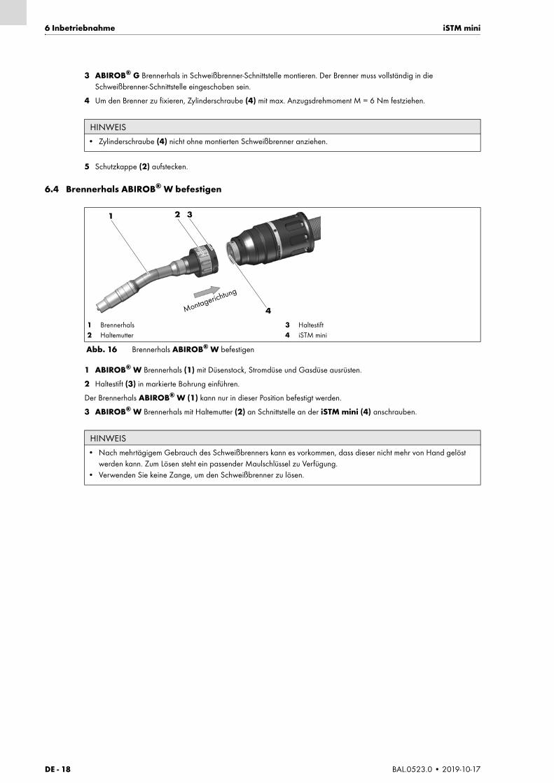
1 ABIROB® W Brennerhals (1) mit Düsenstock, Stromdüse und Gasdüse ausrüsten.
2 Haltestift (3) in markierte Bohrung einführen.
Der Brennerhals ABIROB® W (1) kann nur in dieser Position befestigt werden.
3 ABIROB® W Brennerhals mit Haltemutter (2) an Schnittstelle an der iSTM mini (4) anschrauben.
HINWEIS
• Zylinderschraube (4) nicht ohne montierten Schweißbrenner anziehen.
1 Brennerhals2 Haltemutter
3 Haltestift4 iSTM mini
Abb. 16 Brennerhals ABIROB® W befestigen
HINWEIS
• Nach mehrtägigem Gebrauch des Schweißbrenners kann es vorkommen, dass dieser nicht mehr von Hand gelöst werden kann. Zum Lösen steht ein passender Maulschlüssel zu Verfügung.
• Verwenden Sie keine Zange, um den Schweißbrenner zu lösen.
1 2 3
4Montagerichtung

iSTM mini 6 Inbetriebnahme
BAL.0523.0 • 2019-10-17 DE - 19
6.5 Drahtführung montieren
6.5.1 Standardvariante
1 Schlauchpaket mit Brennerhals und Verschleißteilen ausrüsten.
2 Drahtführung bis Anschlag in das Schlauchpaket einführen.
3 Überstand a (2) ermitteln.
4 Drahtführung von der Vorderseite um Maß a (2) kürzen. Die Drahtführung so kürzen, dass sie nach dem Einbau leicht unter Spannung steht.
5 Drahtführung bis Anschlag in das Schlauchpaket einführen und mit Gewindestift M4 × 5 (3) sichern.
Berücksichtigen Sie folgendes:
9.2 Drahtführung reinigen auf Seite DE-25
HINWEIS
• Neue, noch unbenutzte Drahtführungen müssen auf die tatsächliche Schlauchpaketlänge gekürzt werden.• Beachten Sie bei jedem Drahtführungswechsel (Führungsspirale / Kunststoffseele) die Produktinformationen der
beiliegenden Beipackzettel.• Drahtführung nach Kürzung brennerseitig um 15 mm abisolieren.
1 Hülse2 Überstand a
3 Gewindestift ISO 4027 – M4 × 54 O-Ring
Abb. 17 Überstand Drahtführung ermitteln
HINWEIS
• Die Montage der Drahtführung in diesem Kapitel enthält einen Gewindestift (3). Bei anderen Maschinenanschlüssen ist dieser nicht enthalten.
1 2a 3
4

DE - 20 BAL.0523.0 • 2019-10-17
6 Inbetriebnahme iSTM mini
6.5.2 Variante Wire-BrakeDer Brennerhals für die Wire-Brake Variante muss mit einem speziellen Neckliner ausgerüstet werden.
6.5.3 Drahtführung kürzen
Abb. 17 Überstand Drahtführung ermitteln auf Seite DE-19
1 Schlauchpaket mit Brennerhals und Verschleißteilen ausrüsten.
2 Drahtführung bis Anschlag in das Schlauchpaket einführen.
3 Überstand a (2) ermitteln.
4 Drahtführung von der Vorderseite um Maß a (2) kürzen. Die Drahtführung so kürzen, dass sie nach dem Einbau leicht unter Spannung steht.
5 Drahtführung bis Anschlag in das Schlauchpaket einführen und mit Gewindestift M4 × 5 (3) sichern.
HINWEIS
• Neue, noch unbenutzte Drahtführungen müssen auf die tatsächliche Schlauchpaketlänge gekürzt werden.• Beachten Sie bei jedem Drahtführungswechsel (Führungsspirale / Kunststoffseele) die Produktinformationen der
beiliegenden Beipackzettel.• Drahtführung nach Kürzung brennerseitig um 15 mm abisolieren.
Abb. 18 Drahtführung kürzen
HINWEIS
• Wenn die Drahtführung mit Isolation mehr als Ø 5 mm beträgt, muss die Drahtführung nach Kürzung brennerseitig 15 mm abisoliert werden.
• Der Durchmesser der Drahtspirale ohne Isolation darf nicht größer als Ø 5 mm betragen.
15 mm
≤5
mm
≥5
mm
iSTM mini 7 Betrieb
BAL.0523.0 • 2019-10-17 DE - 21
7 Betrieb
Da die iSTM mini im Schweißprozess des Schweißbrenners eingebunden ist, erfolgen die Bedienschritte nach der Inbetriebnahme des jeweiligen Brenners und der verwendeten Schweißstromquelle. Beachten Sie hierzu die Betriebsanleitungen des entsprechenden Schweißbrenners.
8 Außerbetriebnahme
Die Außerbetriebnahme richtet sich nach dem jeweiligen Schweißbrenner.
Beachten Sie hierzu die Betriebsanleitungen des entsprechenden Schweißbrenners, beziehungsweise der Schweißstromquelle.
WARNUNGElektrischer Schlag. Verbrennung.Herausschleudern von geschmolzenen Teilen.• Es kann zum Stromschlag bei Berührung des Schweißbrenners kommen. Durch den Lichtbogen kann es zum Verblitzen
der Augen und Verbrennungen kommen.• Verwenden Sie eine geeignete Schutzausrüstung nach BGV D1, um eine elektrische Entkopplung der berührbaren,
stromführenden Teile und beim Einrichten der Schweißstätte zu vermeiden.
VORSICHTAusrutschen, Stolpern und Stürzen.Beim Betreten der Roboterzelle kann es zum Ausrutschen auf Drahtresten bzw. Schmiermittel kommen.• Zur Vermeidung geeignete Schutzausrüstung verwenden.• Tragen Sie Ihre persönliche Schutzausrüstung.
HINWEIS
• Beachten Sie die Dokumentation der schweißtechnischen Komponenten.
HINWEIS
• Beachten Sie bei der Außerbetriebnahme die Abschaltprozeduren der schweißtechnischen Komponenten.
DE - 22 BAL.0523.0 • 2019-10-17
9 Wartung und Reinigung iSTM mini
9 Wartung und ReinigungRegelmäßige und dauerhafte Wartung und Reinigung sind Voraussetzung für eine lange Lebensdauer und eine einwandfreie Funktion.
GEFAHRVerletzungsgefahr durch unerwarteten AnlaufFür die gesamte Dauer von Wartungs-, Instandhaltungs-, Montage- bzw. Demontage- und Reparaturarbeiten ist folgendes zu beachten:• Schalten Sie die Stromquelle aus.• Sperren Sie die Druckluftzufuhr ab.• Sperren Sie die Kühlmittelzufuhr ab.• Sperren Sie die Druckluftzufuhr ab.• Trennen Sie alle elektrischen Verbindungen.• Schalten Sie die gesamte Schweißanlage aus.
GEFAHRStromschlagGefährliche Spannung durch fehlerhafte Kabel.• Überprüfen Sie alle spannungsführenden Kabel und Verbindungen auf ordnungsgemäße Installation und
Beschädigungen.• Tauschen Sie schadhafte, deformierte oder verschlissene Teile aus.
WARNUNGVerletzungsgefahrSchwere Verletzungen durch herumwirbelnde Teile.• Tragen Sie beim Ausblasen mit Druckluft geeignete Schutzkleidung, insbesondere eine Schutzbrille.
HINWEIS
• Tragen Sie während der Wartungs- und Reinigungsarbeiten immer Ihre persönliche Schutzausrüstung.

iSTM mini 9 Wartung und Reinigung
BAL.0523.0 • 2019-10-17 DE - 23
9.1 Wartungsintervalle
Beachten Sie die Angaben der EN 60974-4 Inspektion und Prüfung während des Betriebes von Lichtbogenschweißeinrichtungen sowie die jeweiligen Landesgesetze und -richtlinien.
Überprüfen Sie Folgendes:
9.1.1 iSTM mini für ABIROB® G
1 Schutzkappe (1) abziehen.
2 Abdeckung (2) über den Brennerhals abziehen.
3 Freiliegende Teile mit Druckluft ausblasen.
4 Abdeckung (2) und Schutzkappe (1) wieder montieren.
HINWEIS
• Die angegebenen Wartungsintervalle sind Richtwerte und beziehen sich auf den Einschichtbetrieb.
Mehrmals täglich Wöchentlich Monatlich
Befreien Sie den Brennerkopf von Schweißspritzern. Bei starker Spritzerbildung in jeder Schweißpause.
• ABIROB® Brenner mit Hilfe einer Brennerreinigungsstation reinigen. Anschließend mit ABICOR BINZEL- Antispritzerschutzmittel einsprühen.
Wir empfehlen eine wöchentliche Grundreinigung. Reinigungsart und Häufigkeit werden durch den Betreiber des Schweißsystems bestimmt und festgelegt.
• Anschlussverbindungen (Schlauchpaket, Steuerleitung, Masseverbindung) auf festen Sitz prüfen, ggf. festziehen.
Option Wire-Brake
• Drahtklemmvorrichtung, je nach Drahtqualität, 1–2 x reinigen
9.2 Drahtführung reinigen auf Seite DE-25
Tab. 13 Wartungsintervalle
HINWEIS
• Wir empfehlen eine vierteljährliche Reinigung der iSTM mini.
1 Schutzkappe 2 Abdeckung 3 iSTM mini ohne Schutzkappe und Abdeckung
Abb. 19 Reinigung iSTM mini für ABIROB® G
1 2 3
DE - 24 BAL.0523.0 • 2019-10-17
9 Wartung und Reinigung iSTM mini
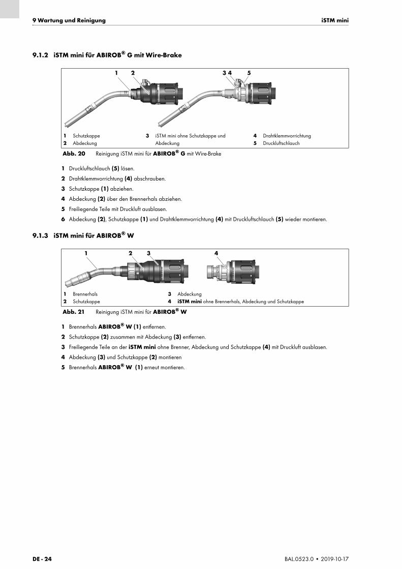
9.1.2 iSTM mini für ABIROB® G mit Wire-Brake
1 Druckluftschlauch (5) lösen.
2 Drahtklemmvorrichtung (4) abschrauben.
3 Schutzkappe (1) abziehen.
4 Abdeckung (2) über den Brennerhals abziehen.
5 Freiliegende Teile mit Druckluft ausblasen.
6 Abdeckung (2), Schutzkappe (1) und Drahtklemmvorrichtung (4) mit Druckluftschlauch (5) wieder montieren.
9.1.3 iSTM mini für ABIROB® W
1 Brennerhals ABIROB® W (1) entfernen.
2 Schutzkappe (2) zusammen mit Abdeckung (3) entfernen.
3 Freiliegende Teile an der iSTM mini ohne Brenner, Abdeckung und Schutzkappe (4) mit Druckluft ausblasen.
4 Abdeckung (3) und Schutzkappe (2) montieren
5 Brennerhals ABIROB® W (1) erneut montieren.
1 Schutzkappe2 Abdeckung
3 iSTM mini ohne Schutzkappe und Abdeckung
4 Drahtklemmvorrichtung5 Druckluftschlauch
Abb. 20 Reinigung iSTM mini für ABIROB® G mit Wire-Brake
1 2 3 4 5
1 Brennerhals2 Schutzkappe
3 Abdeckung4 iSTM mini ohne Brennerhals, Abdeckung und Schutzkappe
Abb. 21 Reinigung iSTM mini für ABIROB® W
1 2 3 4
iSTM mini 10 Störungen und deren Behebung
BAL.0523.0 • 2019-10-17 DE - 25
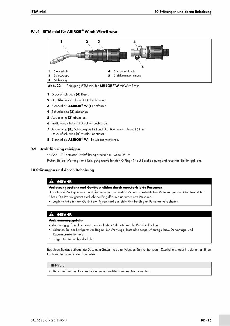
9.1.4 iSTM mini für ABIROB® W mit Wire-Brake
1 Druckluftschlauch (4) lösen.
2 Drahtklemmvorrichtung (5) abschrauben.
3 Brennerhals ABIROB® W (1) entfernen.
4 Schutzkappe (2) abziehen.
5 Abdeckung (3) abziehen.
6 Freiliegende Teile mit Druckluft ausblasen.
7 Abdeckung (3), Schutzkappe (2) und Drahtklemmvorrichtung (5) mit Druckluftschlauch (4) wieder montieren.
8 Brennerhals ABIROB® W (1) wieder montieren.
9.2 Drahtführung reinigen Abb. 17 Überstand Drahtführung ermitteln auf Seite DE-19
Prüfen Sie bei Wartungs- und Reinigungintervallen den O-Ring (4) auf Beschädigung und tauschen Sie ihn ggf. aus.
10 Störungen und deren Behebung
Beachten Sie das beiliegende Dokument Gewährleistung. Wenden Sie sich bei jedem Zweifel und/oder Problemen an Ihren Fachhändler oder an den Hersteller.
1 Brennerhals2 Schutzkappe3 Abdeckung
4 Druckluftschlauch5 Drahtklemmvorrichtung
Abb. 22 Reinigung iSTM mini für ABIROB® W mit Wire-Brake
1 2 3 4
5
GEFAHRVerletzungsgefahr und Geräteschäden durch unautorisierte PersonenUnsachgemäße Reparaturen und Änderungen am Produkt können zu erheblichen Verletzungen und Geräteschäden führen. Die Produktgarantie erlischt bei Eingriff durch unautorisierte Personen.• Jegliche Arbeiten am Gerät bzw. System sind ausschließlich befähigten Personen vorbehalten.
GEFAHRVerbrennungsgefahrVerbrennungsgefahr durch austretendes heißes Kühlmittel und heiße Oberflächen.• Schalten Sie das Kühlgerät vor Beginn der Wartungs-, Instandhaltungs-, Montage- bzw. Demontage- und
Reparaturarbeiten aus.• Tragen Sie Schutzhandschuhe.
HINWEIS
• Beachten Sie die Dokumentation der schweißtechnischen Komponenten.

DE - 26 BAL.0523.0 • 2019-10-17
11 Demontage iSTM mini
11 Demontage
Störung Ursache Behebung
Schlauchpaket lässt sich nicht in iSTM mini einführen
• Steckanschluss und Gasschlauch noch montiert
• Steckanschluss und Gasschlauch demontieren
• Schlauchpaketflansch nicht korrekt auf iSTM mini montiert
• Auf Ausrichtung achten
Gasverlust • O-Ring-Dichtung am Linernippel beschädigt
• O-Ring-Dichtung austauschen
• O-Ring-Dichtung Brennerhals beschädigt • O-Ring-Dichtung austauschen
• Maschinenseitiger Schutzgasanschluss undicht
• ggf. Schutzgasschlauch austauschen
Schweißdraht wird nicht korrekt geführt
• Drahtförderspirale verschmutzt • Drahtförderspirale demontieren und mit Druckluft ausblasen.
• Schutzbrille tragen
• 9 Wartung und Reinigung auf Seite DE-22
• Drahtförderspirale verschlissen • Drahtförderspirale ersetzen
• Drahtförderspirale zu kurz abgelängt • Neue Drahtförderspirale montieren
Drahtklemme bei Wire-Brake Variante funktioniert nicht mehr
• zu starke Schmutzablagerungen • Reinigen der Wire-Brake Komponenten mit Druckluft
• Schutzbrille tragen
• Druckluftzufuhr ist unterbrochen • Druckluftzufuhr anschließen, Knickstellen beseitigen
• Kolben der Drahtklemmvorrichtung ist beschädigt
• Drahtklemmvorrichtung austauschen
Tab. 14 Störungen und deren Behebung
GEFAHRVerletzungsgefahr durch unerwarteten AnlaufFür die gesamte Dauer von Wartungs-, Instandhaltungs-, Montage- bzw. Demontage- und Reparaturarbeiten ist Folgendes zu beachten:• Schalten Sie die Stromquelle aus.• Sperren Sie die Druckluftzufuhr ab.• Sperren Sie die Kühlmittelzufuhr ab.• Trennen Sie alle elektrischen Verbindungen.• Schalten Sie die gesamte Schweißanlage aus.
GEFAHRVerbrennungsgefahrVerbrennungsgefahr durch austretendes heißes Kühlmittel und heiße Oberflächen.• Schalten Sie das Kühlgerät vor Beginn der Wartungs-, Instandhaltungs-, Montage- bzw. Demontage- und
Reparaturarbeiten aus.• Tragen Sie Schutzhandschuhe.
HINWEIS
• Beachten Sie die Dokumentation der schweißtechnischen Komponenten.• Beachten Sie die Informationen in folgendem Kapitel:
8 Außerbetriebnahme auf Seite DE-21.

iSTM mini 12 Entsorgung
BAL.0523.0 • 2019-10-17 DE - 27
1 Schlauchpaket von Drahtvorschub lösen.
2 Schlauchpaket herausziehen.
3 Brennerhals lösen und entfernen.
6.3 Brennerhals von ABIROB® G befestigen auf Seite DE-17
6.4 Brennerhals ABIROB® W befestigen auf Seite DE-18
6.5 Drahtführung montieren auf Seite DE-19
4 iSTM mini von Roboter demontieren.
6.2 Wartungsposition Roboter auf Seite DE-12
12 EntsorgungBei der Entsorgung sind die örtlichen Bestimmungen, Gesetze, Vorschriften, Normen und Richtlinien zu beachten. Um das Produkt ordnungsgemäß zu entsorgen, müssen Sie es zuerst demontieren.
11 Demontage auf Seite DE-26
12.1 WerkstoffeDieses Produkt besteht zum größten Teil aus Kunststoffen, Stahl und Buntmetallen. Stahl und Buntmetalle können in Stahl- und Hüttenwerken wieder eingeschmolzen werden und sind dadurch nahezu unbegrenzt wiederverwertbar. Die verwendeten Kunststoffe sind gekennzeichnet, so dass eine Sortierung und Fraktionierung der Materialien zum späteren Recycling vorbereitet ist.
12.2 BetriebsmittelÖle, Schmierfette und Reinigungsmittel dürfen nicht den Boden belasten und in die Kanalisation gelangen. Diese Stoffe müssen in geeigneten Behältern aufbewahrt, transportiert und entsorgt werden. Beachten Sie dabei die entsprechenden örtlichen Bestimmungen und die Hinweise zur Entsorgung der vom Betriebsmittelhersteller vorgegebenen Sicherheitsdatenblätter. Kontaminierte Reinigungswerkzeuge (Pinsel, Lappen usw.) müssen ebenfalls entsprechend den Angaben des Betriebsmittelherstellers entsorgt werden.
12.3 VerpackungenABICOR BINZEL hat die Transportverpackung auf das Notwendigste reduziert. Bei der Auswahl der Verpackungsmaterialien wird auf eine mögliche Wiederverwertung geachtet.
GEFAHRStromschlagGefährliche Spannung durch fehlerhafte Kabel.• Überprüfen Sie alle spannungsführenden Kabel und Verbindungen auf ordnungsgemäße Installation und
Beschädigungen.• Tauschen Sie schadhafte, deformierte oder verschlissene Teile aus.
EN - 2 BAL.0523.0 • 2019-10-17
iSTM mini
EN Translation of the original operating instructions
© The manufacturer reserves the right, at any time and without prior notice, to make such changes and amendments to these operating instructions as become necessary due to misprints, inaccuracies or product enhancements. Such changes will, however, be incorporated into subsequent editions of the operating instructions.
All brand names and trademarks that appear in these operating instructions are the property of their respective owners/manufacturers.
Our latest product documents as well as all contact details for the ABICOR BINZEL national subsidiaries and partners worldwide can be found on our website at www.binzel-abicor.com
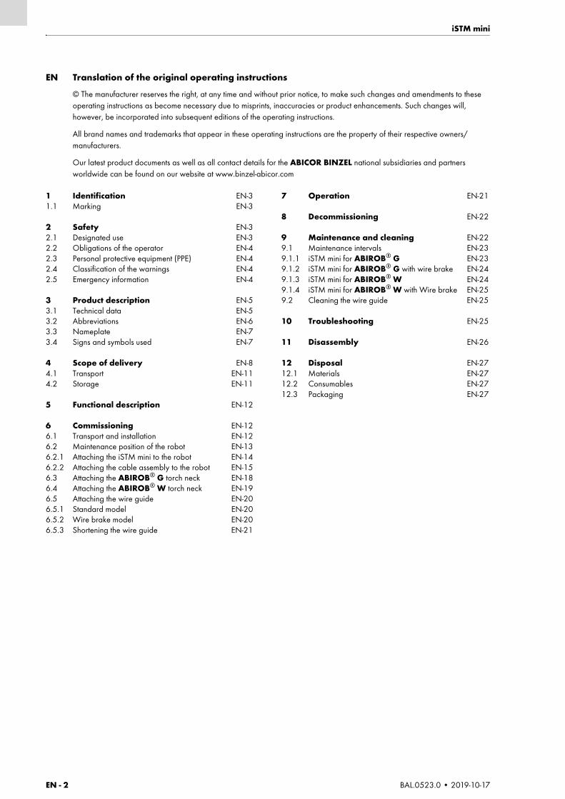
1 Identification EN-31.1 Marking EN-3
2 Safety EN-32.1 Designated use EN-32.2 Obligations of the operator EN-42.3 Personal protective equipment (PPE) EN-42.4 Classification of the warnings EN-42.5 Emergency information EN-4
3 Product description EN-53.1 Technical data EN-53.2 Abbreviations EN-63.3 Nameplate EN-73.4 Signs and symbols used EN-7
4 Scope of delivery EN-84.1 Transport EN-114.2 Storage EN-11
5 Functional description EN-12
6 Commissioning EN-126.1 Transport and installation EN-126.2 Maintenance position of the robot EN-136.2.1 Attaching the iSTM mini to the robot EN-146.2.2 Attaching the cable assembly to the robot EN-156.3 Attaching the ABIROB® G torch neck EN-186.4 Attaching the ABIROB® W torch neck EN-196.5 Attaching the wire guide EN-206.5.1 Standard model EN-206.5.2 Wire brake model EN-206.5.3 Shortening the wire guide EN-21
7 Operation EN-21
8 Decommissioning EN-22
9 Maintenance and cleaning EN-229.1 Maintenance intervals EN-239.1.1 iSTM mini for ABIROB® G EN-239.1.2 iSTM mini for ABIROB® G with wire brake EN-249.1.3 iSTM mini for ABIROB® W EN-249.1.4 iSTM mini for ABIROB® W with Wire brake EN-259.2 Cleaning the wire guide EN-25
10 Troubleshooting EN-25
11 Disassembly EN-26
12 Disposal EN-2712.1 Materials EN-2712.2 Consumables EN-2712.3 Packaging EN-27
iSTM mini 1 Identification
BAL.0523.0 • 2019-10-17 EN - 3
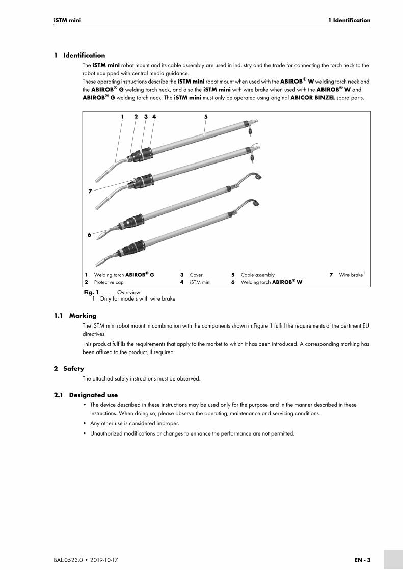
1 IdentificationThe iSTM mini robot mount and its cable assembly are used in industry and the trade for connecting the torch neck to the robot equipped with central media guidance.These operating instructions describe the iSTM mini robot mount when used with the ABIROB® W welding torch neck and the ABIROB® G welding torch neck, and also the iSTM mini with wire brake when used with the ABIROB® W and ABIROB® G welding torch neck. The iSTM mini must only be operated using original ABICOR BINZEL spare parts.
1.1 MarkingThe iSTM mini robot mount in combination with the components shown in Figure 1 fulfill the requirements of the pertinent EU directives.
This product fulfills the requirements that apply to the market to which it has been introduced. A corresponding marking has been affixed to the product, if required.
2 SafetyThe attached safety instructions must be observed.
2.1 Designated use• The device described in these instructions may be used only for the purpose and in the manner described in these
instructions. When doing so, please observe the operating, maintenance and servicing conditions.
• Any other use is considered improper.
• Unauthorized modifications or changes to enhance the performance are not permitted.
1 Welding torch ABIROB® G2 Protective cap
3 Cover4 iSTM mini
5 Cable assembly6 Welding torch ABIROB® W
7 Wire brake1
1 Only for models with wire brakeFig. 1 Overview
1 2 3 4 5
6
7

EN - 4 BAL.0523.0 • 2019-10-17
2 Safety iSTM mini
2.2 Obligations of the operator• Only the following personnel may work on the device:
• those who are familiar with the basic regulations and accident prevention;
• those who have been instructed on how to handle the device;
• those who have read and understand these operating instructions;
• those who have read and understood the attached ‘Safety instructions’ document;
• those who have been trained accordingly;
• those who are able to recognize possible risks because of their special training, knowledge, and experience.
• Keep other people out of the work area.
• Please observe the occupational health and safety regulations of the relevant country.
• Observe the regulations on occupational safety and accident prevention.
2.3 Personal protective equipment (PPE)To prevent danger to the user, these instructions recommend the use of personal protective equipment (PPE).
• This consists of protective clothing, safety goggles, a class P3 respiratory mask, protective gloves and safety shoes.
2.4 Classification of the warningsThe warnings used in the operating instructions are divided into four different levels and shown prior to potentially dangerous work steps. Arranged in descending order of importance, they have the following meanings:
2.5 Emergency informationIn the event of an emergency, immediately disconnect the following supplies:
• Electrical power supply
• Compressed air supply
• Gas supply
• Coolant supply
Further measures can be found in the operating instructions for the power source or the documentation for other peripheral devices.
DANGERDescribes an imminent threatening danger. If not avoided, this will result in fatal or extremely critical injuries.
WARNINGDescribes a potentially dangerous situation. If not avoided, this may result in serious injuries.
CAUTIONDescribes a potentially harmful situation. If not avoided, this may result in slight or minor injuries.
NOTICE
Describes the risk of impairing work results or potential material damage to the equipment.

iSTM mini 3 Product description
BAL.0523.0 • 2019-10-17 EN - 5
3 Product description
3.1 Technical data
WARNINGHazards caused by improper useIf improperly used, the device can present risks to persons, animals and material property.• Use the device according to its designated use only.• Do not convert and modify the device to enhance its performance without authorization.• Only qualified personnel are permitted to perform work on the device or system.
Transport and storage −10° C to +55° C
Relative humidity Up to 70% at 20° C
Tab. 1 Ambient conditions during operation
Storage in a closed environment, ambient temperature
−10° C to +55° C
Ambient temperature for shipment −25° C to +55° C
Relative humidity Up to 70% at 20° C
Tab. 2 Ambient conditions for transport and storage
Operating pressure 6 bar
Max. operating pressure 10 bar
Hose diameter, inner 2.5 mm
Hose diameter, outer 4 mm
Tab. 3 Pneumatic system wire brake
Dimensions of iSTM mini for ABIROB® G Ø = 79 mm L = 162 mm
Dimensions of iSTM mini for ABIROB® W / Wire brake
Ø = 79 mm L = 155 mm / 175 mm
Weight of iSTM mini for ABIROB® G with connection module (without torch and cable assembly)
0.65 kg
Weight of iSTM mini for ABIROB® W with connection module (without torch and cable assembly)
0.84 kg
Weight of iSTM mini ABIROB W with connection module, wire brake model(without torch and cable assembly)
0.94 kg
Tab. 4 General data
A4 = Torsion max. ±155° A5 = Bend max. +90°/−135° A6 = Torsion max. ±200°
Fig. 2 Maximum load of cable assembly
A4: ±155° A6: ±200°
A5: +90°/−135°

EN - 6 BAL.0523.0 • 2019-10-17
3 Product description iSTM mini
The load data was determined under standard conditions, at low to medium heat of reflection, free air circulation and an ambient temperature of approx. 28° C. When used under more strenuous conditions, the load data must be reduced by 10–20%.
3.2 Abbreviations
NOTICE
• Torsion A4 and A6 max. ±355°.• To ensure proper attachment of the iSTM mini and cable assembly, you must set the 4th and 5th axes of the robot as
follows: 4th axis = neutral position, 5th axis = tilted by 10°, 6th axis = neutral position
ABIROB® G ABIROB® W
Type of voltage DC
Polarity of the electrodes Usually positive
Wire types Commercially available round wires
Type of use Automatic
Voltage rating Peak value of 141 V
Protection type of the device connections (EN 60529)
IP3X
Shielding gas (EN ISO 14175) CO2 and M21
Tab. 5 General torch data with reference to EN 60974-7
Type Type of cooling
Load1
1For pulse arcs, the load data is reduced by up to 35%
Duty cycle
Wire ø Gas flow Cooling data
Cooling capacity
Flow Flow pressure
CO2 M21 Min. Min. Min. Max.
ABIROB® A A % mm l/min W l/min bar bar
G350 Air 350 300 100 0.8–1.2 Approx. 20 800 Approx. 20 / /
G360 Air 360 290 100 0.8–1.6 Approx. 20 800 Approx. 20 / /
G500 Air 500 400 100 0.8–1.6 Approx. 20 800 Approx. 20 / /
W300 Liquid 330 300 100 0.8–1.2 Approx. 20 800 1.25 1.5 3.5
W500 Liquid 550 500 100 0.8–1.6 Approx. 20 800 1.25 1.5 3.5
W600 Liquid 600 100 100 0.8–1.6 Approx. 20 800 1.25 1.5 3.5
Tab. 6 Product-specific torch data (EN 60974-7) in connection with iSTM mini
ABIROB® G Automatic welding torch, air-cooled
ABIROB® W Automatic welding torch, liquid-cooled
Tab. 7 Abbreviations and term definitions
iSTM mini 3 Product description
BAL.0523.0 • 2019-10-17 EN - 7
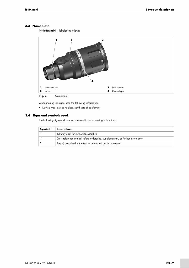
3.3 NameplateThe iSTM mini is labeled as follows:
When making inquiries, note the following information:
• Device type, device number, certificate of conformity
3.4 Signs and symbols usedThe following signs and symbols are used in the operating instructions:
1 Protective cap2 Cover
3 Item number4 Device type
Fig. 3 Nameplate
1 2 3
4
Symbol Description
• Bullet symbol for instructions and lists
Cross-reference symbol refers to detailed, supplementary or further information
1 Step(s) described in the text to be carried out in succession

EN - 8 BAL.0523.0 • 2019-10-17
4 Scope of delivery iSTM mini
4 Scope of delivery
iSTM mini for ABIROB® G
*Size and quantity of cylinder head screws depend on robot type.
1 Protective cap2 Cover
3 Cylinder head screw M4 × 164 Connection module5 Countersunk screw M3 × 5
6 Front cover7 Cylinder head screw M3 × 68 Rear cover
9 iSTM mini10 Cylinder head screw
M4 × 12
Fig. 4 Scope of delivery of iSTM mini for ABIROB® G
• Robot mount for iSTM mini • 8 cylinder head screws M4 × 12*
• Cable assembly for iSTM mini • 7 cylinder head screws M4 × 16
• Rear cover • 2 cylinder head screws M3 × 6
• Front cover • 2 countersunk screws M3 × 5
• Protective cap • Socket wrench AF11
• Cover • Düsofix silicone-free seal grease, 10 g tin
• Liner • Certificate of conformity
• Straight push-in fitting • Operating instructions
• Shielding gas hose Ø 6 mm
Tab. 8 Scope of delivery of iSTM mini for ABIROB® G
1 2 3 4 5 6 7 8 9
10

iSTM mini 4 Scope of delivery
BAL.0523.0 • 2019-10-17 EN - 9
iSTM mini for ABIROB® G with wire brake
*Size and quantity of cylinder head screws depend on robot type.
1 Protective cap2 Cover
3 Cylinder head screw M4 × 164 Connection module5 Countersunk screw M3 × 5
6 Front cover7 Cylinder head screw M3 × 68 Rear cover
9 iSTM mini10 Cylinder head screw
M4 × 12
Fig. 5 Scope of delivery of iSTM mini for ABIROB® G with wire brake
• Robot mount for iSTM mini • 8 cylinder head screws M4 × 12*
• Cable assembly for iSTM mini • 7 cylinder head screws M4 × 16
• Rear cover • 2 cylinder head screws M3 × 6
• Front cover • 2 countersunk screws M3 × 5
• Protective cap • Socket wrench AF11
• Cover • Düsofix silicone-free seal grease, 10 g tin
• Liner • Certificate of conformity
• Straight push-in fitting • Operating instructions
• Shielding gas hose Ø 6 mm
Tab. 9 Scope of delivery of iSTM mini for ABIROB® G with wire brake
1 2 3 4 5 6 7 8
9

EN - 10 BAL.0523.0 • 2019-10-17
4 Scope of delivery iSTM mini
iSTM mini for ABIROB® W
*Size and quantity of cylinder head screws depend on robot type.
1 Protective cap2 Cover
3 Cylinder head screw M4 × 164 iCAT mini W CAl complete
5 iSTM mini6 Cylinder head screw M4 × 12
Fig. 6 Scope of delivery of iSTM mini for ABIROB® W
• Robot mount for iSTM mini • 8 cylinder head screws M4 × 12*
• Cable assembly for iSTM mini W • 7 cylinder head screws M4 × 16
• Cover • Düsofix silicone-free seal grease, 10 g tin
• Protective cap • Certificate of conformity
• Liner • Operating instructions
Tab. 10 Scope of delivery of iSTM mini for ABIROB® W
1 2 3 4 5 6

iSTM mini 4 Scope of delivery
BAL.0523.0 • 2019-10-17 EN - 11
iSTM mini for ABIROB® W with wire brake
*Size and quantity of cylinder head screws depend on robot type.
Order the equipment parts and wear parts separately. The order data and ID numbers for the equipment parts and wear parts can be found in the current product catalog. Contact details for consultation and placing orders can be found online at www.binzel-abicor.com.
4.1 TransportAlthough the items delivered are carefully checked and packaged, it is not possible to fully rule out the risk of transport damage.
4.2 StoragePhysical storage conditions in a closed environment:
3.1 Technical data on page EN-5
1 Protective cap2 Cover3 Cylinder head screw M4 × 16
4 iCAT mini W CAl complete5 iSTM mini6 Cylinder head screw M4 × 12
7 Wire brake
Fig. 7 Scope of delivery of iSTM mini for ABIROB® W with wire brake
• Robot mount for iSTM mini • 8 Cylinder head screw M4 × 12*
• Cable assembly for iSTM mini W • 7 Cylinder head screw M4 × 16
• Cover • Düsofix silicone-free seal grease, 10 g tin
• Protective cap • Certificate of conformity
• Liner • Operating instructions
• Wire brake
Tab. 11 Scope of delivery of iSTM mini for ABIROB® W with wire brake
1 2 3 4 5 6
7
Goods-in inspection Use the delivery note to check that everything has been delivered.Check the delivery for damage (visual inspection).
In case of complaints If the delivery has been damaged during transport, contact the last carrier immediately. Retain the packaging for potential inspection by the carrier.
Packaging for returns Where possible, use the original packaging and the original packaging material. If you have any questions concerning the packaging and/or how to secure an item during shipment, please consult your supplier.
Tab. 12 Transport

EN - 12 BAL.0523.0 • 2019-10-17
5 Functional description iSTM mini
5 Functional descriptionThe iSTM mini robot mount is used to mount welding torches in an exact position. It is attached to the robot with cylinder head screws.
6 Commissioning
6.1 Transport and installation
DANGERRisk of injury due to unexpected startThe following instructions must be adhered to throughout all maintenance, servicing, assembly, disassembly and repair work:• Switch off the power source.• Close off the gas supply.• Close off the coolant supply.• Close off the compressed air supply.• Disconnect all electrical connections.• Switch off the entire welding system.
NOTICE
• Please take note of the following instructions:
3 Product description on page EN-5
DANGERElectric shockDangerous voltage due to defective cables.• Check all live cables and connections for proper installation and damage.• Replace any damaged, deformed or worn parts.• Power to the device should be disconnected when mounting all parts.
CAUTIONRisk of injuryPhysical injury due to falling devices and add-on components.• Select a suitable location when unpacking the device.• Avoid abrupt lifting and setting down.• Do not lift the components over persons or other devices.• Transport the components in an upright position.• Use suitable assistance to help mount the device.• Position the robot so it can be easily mounted.
6.2 Maintenance position of the robot on page EN-13
• Make sure it is standing firmly on the ground or other surface.• Wear your personal protective equipment: safety shoes with steel toe caps, protective gloves, safety helmet, ear
protectors.• Send bystanders out of the danger zone.• Note the weight of the individual components.
3.1 Technical data on page EN-5

iSTM mini 6 Commissioning
BAL.0523.0 • 2019-10-17 EN - 13
6.2 Maintenance position of the robot
For standard welding positions, we recommend the following axis positions for the mounting of the cable assembly:
CAUTIONPuncture or cut-in wounds may be caused by the wire electrodeDamage to the eyes could occur when connecting the pneumatic line.For the model with wire brake, a leaky or improperly connected line can lead to escaping compressed air, whereby particles can make contact with the eye.Follow the following connection sequence to prevent this:• Connect the compressed air-hose to the wire brake.• Connect the compressed air supply.• Wear your personal protective equipment.
CAUTIONRisk of topplingPhysical injury or damage to components due to improper assembly.• Disconnect the supply lines.• Place the components on a suitable base (flat, solid, dry) on which they will not topple over. • Note the maximum angle of tilt of 10°.
NOTICE
• Ensure clear access to the control elements and connections.• Protect the components against rain and direct sunlight.• Use the device only in dry, clean and well-ventilated rooms.
NOTICE
• The maintenance position has to be approached with the robot.• The wire feeder will be mounted in different ways depending on the manufacturer. Please observe the operating
instructions of the relevant wire feeder.
Fig. 8 Overview of robot axes
J4 (A4)
J6(A6)
J5(A5)
+
+
+
−
−
−
EN - 14 BAL.0523.0 • 2019-10-17
6 Commissioning iSTM mini
In order to determine the optimum position of the wire feeder at extreme welding positions, we recommend the following axis positions:
A6 > ±100°, A5 > ±90°, A4 > ±100°
This procedure avoids extreme stress on the cable assembly.
1 Loosen the wire feeder (1).
2 Align the cable assembly (2) in the specified direction.
6.2.1 Attaching the iSTM mini to the robot
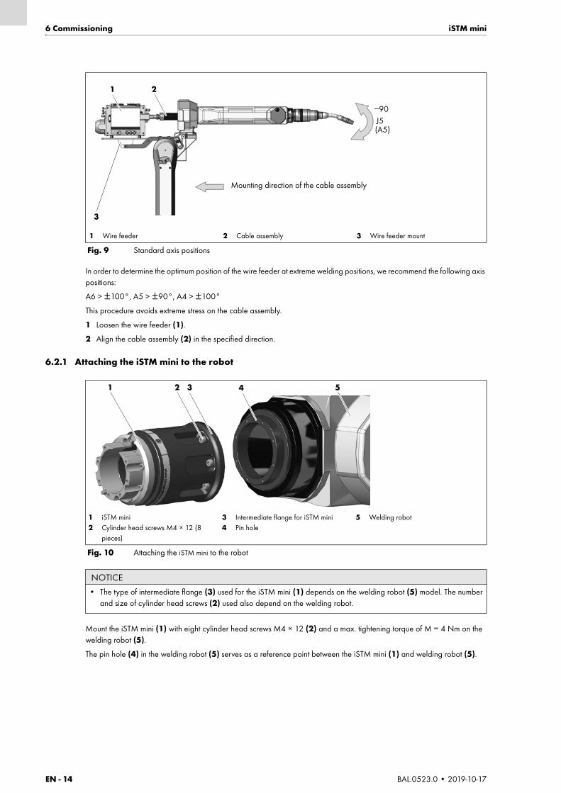
Mount the iSTM mini (1) with eight cylinder head screws M4 × 12 (2) and a max. tightening torque of M = 4 Nm on the welding robot (5).
The pin hole (4) in the welding robot (5) serves as a reference point between the iSTM mini (1) and welding robot (5).
1 Wire feeder 2 Cable assembly 3 Wire feeder mount
Fig. 9 Standard axis positions
Mounting direction of the cable assembly
1
3
2
J5(A5)
−90
1 iSTM mini2 Cylinder head screws M4 × 12 (8
pieces)
3 Intermediate flange for iSTM mini4 Pin hole
5 Welding robot
Fig. 10 Attaching the iSTM mini to the robot
NOTICE
• The type of intermediate flange (3) used for the iSTM mini (1) depends on the welding robot (5) model. The number and size of cylinder head screws (2) used also depend on the welding robot.
1 2 3 54
iSTM mini 6 Commissioning
BAL.0523.0 • 2019-10-17 EN - 15
6.2.2 Attaching the cable assembly to the robot
iSTM mini for ABIROB® G
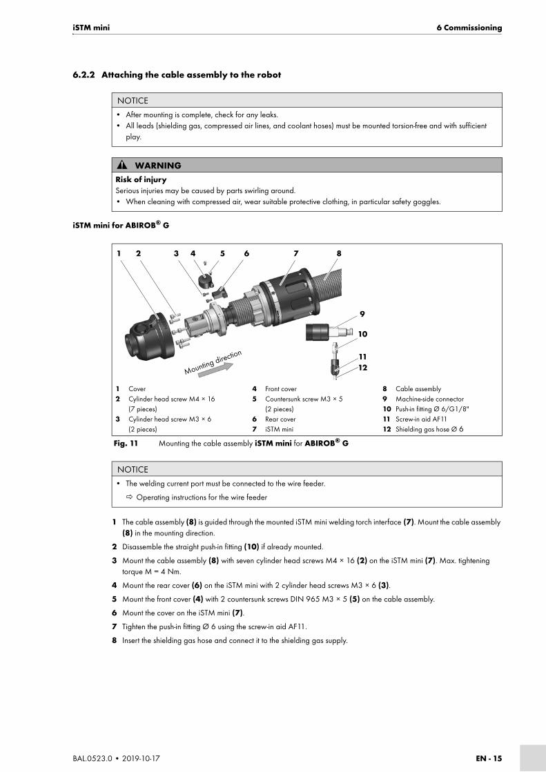
1 The cable assembly (8) is guided through the mounted iSTM mini welding torch interface (7). Mount the cable assembly (8) in the mounting direction.
2 Disassemble the straight push-in fitting (10) if already mounted.
3 Mount the cable assembly (8) with seven cylinder head screws M4 × 16 (2) on the iSTM mini (7). Max. tightening torque M = 4 Nm.
4 Mount the rear cover (6) on the iSTM mini with 2 cylinder head screws M3 × 6 (3).
5 Mount the front cover (4) with 2 countersunk screws DIN 965 M3 × 5 (5) on the cable assembly.
6 Mount the cover on the iSTM mini (7).
7 Tighten the push-in fitting Ø 6 using the screw-in aid AF11.
8 Insert the shielding gas hose and connect it to the shielding gas supply.
NOTICE
• After mounting is complete, check for any leaks.• All leads (shielding gas, compressed air lines, and coolant hoses) must be mounted torsion-free and with sufficient
play.
WARNINGRisk of injurySerious injuries may be caused by parts swirling around.• When cleaning with compressed air, wear suitable protective clothing, in particular safety goggles.
1 Cover2 Cylinder head screw M4 × 16
(7 pieces)3 Cylinder head screw M3 × 6
(2 pieces)
4 Front cover5 Countersunk screw M3 × 5
(2 pieces)6 Rear cover7 iSTM mini
8 Cable assembly9 Machine-side connector10 Push-in fitting Ø 6/G1/8"11 Screw-in aid AF1112 Shielding gas hose Ø 6
Fig. 11 Mounting the cable assembly iSTM mini for ABIROB® G
NOTICE
• The welding current port must be connected to the wire feeder.
Operating instructions for the wire feeder
Mounting direction
1 2 3 4 5 6 7 8
9
10
1112

EN - 16 BAL.0523.0 • 2019-10-17
6 Commissioning iSTM mini
iSTM mini for ABIROB® G with wire brake
1 The cable assembly (8) is guided through the mounted iSTM mini welding torch interface (7). Mount the cable assembly (8) in the mounting direction.
2 Disassemble the straight push-in fitting (10) if already mounted.
3 Mount the straight cable assembly (8) with seven cylinder head screws M4 × 16 (2) on the iSTM mini (7). Max. tightening torque M = 4 Nm.
4 Mount the rear cover on the iSTM mini (7) with 2 cylinder head screws M3 × 6 (3).
5 Guide the compressed air supply hose (5) for the wire brake (4) through the hole in the rear cover (6).
6 Mount the cover on the iSTM mini (7).
7 Mount the wire brake (4).
8 Tighten the push-in fitting Ø 6 using the screw-in aid AF11.
9 Insert the shielding gas hose and connect it to the shielding gas supply.
1 Cover2 Cylinder head screw M4 × 16 (7 pieces)3 Cylinder head screw M3 × 6 (2 pieces)4 Wire brake
5 Hose for compressed air supply6 Rear cover7 iSTM mini8 Cable assembly
9 Machine-side connector10 Push-in fitting Ø 6/G1/8"11 Screw-in aid AF1112 Shielding gas hose Ø 6
Fig. 12 Mounting the cable assembly iSTM mini for ABIROB® G with wire brake
NOTICE
• The welding current port must be connected to the wire feeder.
Operating instructions for wire feeder
Mounting direction
1 2 3 4 5 6 7 8
10
1112
9
iSTM mini 6 Commissioning
BAL.0523.0 • 2019-10-17 EN - 17
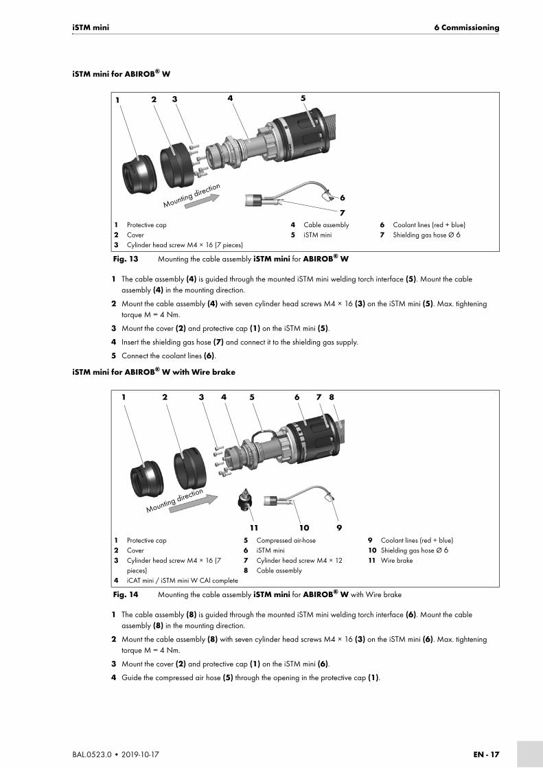
iSTM mini for ABIROB® W
1 The cable assembly (4) is guided through the mounted iSTM mini welding torch interface (5). Mount the cable assembly (4) in the mounting direction.
2 Mount the cable assembly (4) with seven cylinder head screws M4 × 16 (3) on the iSTM mini (5). Max. tightening torque M = 4 Nm.
3 Mount the cover (2) and protective cap (1) on the iSTM mini (5).
4 Insert the shielding gas hose (7) and connect it to the shielding gas supply.
5 Connect the coolant lines (6).
iSTM mini for ABIROB® W with Wire brake
1 The cable assembly (8) is guided through the mounted iSTM mini welding torch interface (6). Mount the cable assembly (8) in the mounting direction.
2 Mount the cable assembly (8) with seven cylinder head screws M4 × 16 (3) on the iSTM mini (6). Max. tightening torque M = 4 Nm.
3 Mount the cover (2) and protective cap (1) on the iSTM mini (6).
4 Guide the compressed air hose (5) through the opening in the protective cap (1).
1 Protective cap2 Cover3 Cylinder head screw M4 × 16 (7 pieces)
4 Cable assembly5 iSTM mini
6 Coolant lines (red + blue)7 Shielding gas hose Ø 6
Fig. 13 Mounting the cable assembly iSTM mini for ABIROB® W
Mounting direction
1 2 3 4 5
6
7
1 Protective cap2 Cover3 Cylinder head screw M4 × 16 (7
pieces)4 iCAT mini / iSTM mini W CAl complete
5 Compressed air-hose6 iSTM mini7 Cylinder head screw M4 × 128 Cable assembly
9 Coolant lines (red + blue)10 Shielding gas hose Ø 611 Wire brake
Fig. 14 Mounting the cable assembly iSTM mini for ABIROB® W with Wire brake
1 2 3 4 5 6 7 8
91011
Mounting direction
EN - 18 BAL.0523.0 • 2019-10-17
6 Commissioning iSTM mini
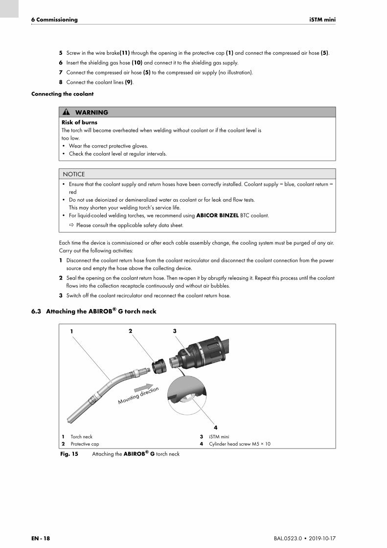
5 Screw in the wire brake(11) through the opening in the protective cap (1) and connect the compressed air hose (5).
6 Insert the shielding gas hose (10) and connect it to the shielding gas supply.
7 Connect the compressed air hose (5) to the compressed air supply (no illustration).
8 Connect the coolant lines (9).
Connecting the coolant
Each time the device is commissioned or after each cable assembly change, the cooling system must be purged of any air. Carry out the following activities:
1 Disconnect the coolant return hose from the coolant recirculator and disconnect the coolant connection from the power source and empty the hose above the collecting device.
2 Seal the opening on the coolant return hose. Then re-open it by abruptly releasing it. Repeat this process until the coolant flows into the collection receptacle continuously and without air bubbles.
3 Switch off the coolant recirculator and reconnect the coolant return hose.
6.3 Attaching the ABIROB® G torch neck
WARNINGRisk of burnsThe torch will become overheated when welding without coolant or if the coolant level is too low.• Wear the correct protective gloves.• Check the coolant level at regular intervals.
NOTICE
• Ensure that the coolant supply and return hoses have been correctly installed. Coolant supply = blue, coolant return = red
• Do not use deionized or demineralized water as coolant or for leak and flow tests.This may shorten your welding torch’s service life.
• For liquid-cooled welding torches, we recommend using ABICOR BINZEL BTC coolant.
Please consult the applicable safety data sheet.
1 Torch neck2 Protective cap
3 iSTM mini4 Cylinder head screw M5 × 10
Fig. 15 Attaching the ABIROB® G torch neck
1 2 3
4
Mounting direction

iSTM mini 6 Commissioning
BAL.0523.0 • 2019-10-17 EN - 19
1 Equip the ABIROB® G torch neck (1) with a tip adaptor, contact tip, and gas nozzle.
ABIROB® 350 GC instruction leaflet
2 Loosen the cylinder head screw (4).
3 Mount the ABIROB® G torch neck in the welding torch interface. The torch must be inserted all the way into the welding torch interface.
4 To fix the torch, tighten the cylinder head screw (4) with a max. tightening torque of M = 6 Nm.
5 Put the protective cap (2) back on.
6.4 Attaching the ABIROB® W torch neck
1 Equip the ABIROB® W torch neck (1) with a tip adaptor, contact tip, and gas nozzle.
2 Insert the positioning pin (3) in the marked bore.
The ABIROB® W torch neck (1) may be attached in this position only.
3 Screw the ABIROB® W torch neck with retaining nut (2) on to the iSTM mini interface (4).
NOTICE
• Do not tighten the cylinder head screw (4) unless the welding torch is already mounted.
1 Torch neck2 Retaining nut
3 Positioning pin4 iSTM mini
Fig. 16 Attaching the ABIROB® W torch neck
NOTICE
• After repeated use, it may not be possible to loosen the welding torch by hand. A wrench is provided to assist with loosening.
• Do not use pliers to loosen the welding torch.
1 2 3
4Mounting direction

EN - 20 BAL.0523.0 • 2019-10-17
6 Commissioning iSTM mini
6.5 Attaching the wire guide
6.5.1 Standard model
1 Equip the cable assembly with torch neck and wear parts.
2 Insert the wire guide until it reaches the stop in the cable assembly.
3 Determine excess length a (2).
4 Shorten the wire guide on the front side by dimension a (2). Shorten it so that it is slightly tight after installation.
5 Insert the wire guide in the cable assembly until it reaches the stop and secure with set screw M4 × 5 (3).
Observe the following:
9.2 Cleaning the wire guide on page EN-25
6.5.2 Wire brake modelThe torch neck for the wire brake model must be equipped with a special neckliner.
NOTICE
• New wire guide liners that have not yet been used must be shortened to the actual length of the cable assembly.• Each time the wire guide is changed (liner, PA liner), make sure to consult the product information in the instruction
leaflets provided.• Strip the wire guide 15 mm on the torch side after shortening it.
1 Sleeve2 Excess length a
3 Set screw ISO 4027 – M4 × 54 O-ring
Fig. 17 Determining the excess length of the wire guide
NOTICE
• In this section, the wire guide assembly includes one set screw (3). It is not included in other machine connections.
1 2a 3
4
NOTICE
• New wire guide liners that have not yet been used must be shortened to the actual length of the cable assembly.• Each time the wire guide is changed (liner, PA liner), make sure to consult the product information in the instruction
leaflets provided.• Strip the wire guide 15 mm on the torch side after shortening it.
iSTM mini 7 Operation
BAL.0523.0 • 2019-10-17 EN - 21
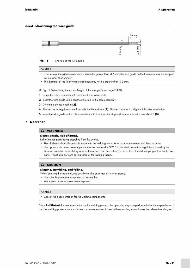
6.5.3 Shortening the wire guide
Fig. 17 Determining the excess length of the wire guide on page EN-20
1 Equip the cable assembly with torch neck and wear parts.
2 Insert the wire guide until it reaches the stop in the cable assembly.
3 Determine excess length a (2).
4 Shorten the wire guide on the front side by dimension a (2). Shorten it so that it is slightly tight after installation.
5 Insert the wire guide in the cable assembly until it reaches the stop and secure with set screw M4 × 5 (3).
7 Operation
Since the iSTM mini is integrated in the torch’s welding process, the operating steps are performed after the respective torch and the welding power source have been put into operation. Observe the operating instructions of the relevant welding torch.
Fig. 18 Shortening the wire guide
NOTICE
• If the wire guide with insulation has a diameter greater than Ø 5 mm, the wire guide on the torch-side must be stripped 15 mm after shortening it.
• The diameter of the liner without insulation may not be greater than Ø 5 mm.
15 mm
≤5
mm
≥5
mm
WARNINGElectric shock. Risk of burns.Risk of molten parts being propelled from the device.• Risk of electric shock if contact is made with the welding torch. An arc can stun the eyes and lead to burns.• Use appropriate protective equipment in accordance with BGV D1 (accident prevention regulations issued by the
German Institution for Statutory Accident Insurance and Prevention) to prevent electrical decoupling of touchable, live parts. It must also be worn during setup of the welding facility.
CAUTIONSlipping, stumbling, and falling.When entering the robot cell, it is possible to slip on scraps of wire or grease.• Use suitable protective equipment to prevent this.• Wear your personal protective equipment.
NOTICE
• Consult the documentation for the welding components.

EN - 22 BAL.0523.0 • 2019-10-17
8 Decommissioning iSTM mini
8 Decommissioning
Decommissioning depends on the respective welding torch.
Observe the operating instructions of the relevant welding torch and welding power source.
9 Maintenance and cleaningScheduled maintenance and cleaning are prerequisites for a long service life and trouble-free operation.
NOTICE
• When decommissioning the system, ensure that the procedures for switching off the welding components are observed.
DANGERRisk of injury due to unexpected startThe following instructions must be followed during all maintenance, servicing, assembly, disassembly, and repair work:• Switch off the power source.• Close off the compressed air supply.• Close off the coolant supply.• Close off the compressed air supply.• Disconnect all electrical connections.• Switch off the entire welding system.
DANGERElectric shockDangerous voltage due to defective cables.• Check all live cables and connections for proper installation and damage.• Replace any damaged, deformed or worn parts.
WARNINGRisk of injurySerious injuries may be caused by parts swirling around.• When cleaning with compressed air, wear suitable protective clothing, in particular safety goggles.
NOTICE
• Always wear your personal protective equipment when performing maintenance and cleaning work.

iSTM mini 9 Maintenance and cleaning
BAL.0523.0 • 2019-10-17 EN - 23
9.1 Maintenance intervals
When using arc welding equipment, always observe the provisions of EN 60974-4 Inspection and testing, as well as any national laws and regulations.
Check the following:
9.1.1 iSTM mini for ABIROB® G
1 Remove the protective cap (1).
2 Pull off the cover (2) over the torch neck.
3 Clean exposed parts with compressed air.
4 Remount the cover (2) and put on the protective cap (1) again.
NOTICE
• The specified maintenance intervals are standard values and refer to single-shift operation.
Several times a day Weekly Monthly
Clean weld spatter from the torch head. In the case of heavy weld spatter build-up, clean during each welding break.
• Clean the ABIROB® torch with a torch cleaning station. Then spray with ABICOR BINZEL anti-spatter fluid.
We recommend basic cleaning once a week. The type and frequency of cleaning shall be determined and established by the operator of the welding system.
• Check that the connections (cable assembly, control lead, ground) are secure. Tighten if necessary.
Optional wire brake
• Clean the wire brake 1–2 times depending on the quality of the wire
9.2 Cleaning the wire guide on page EN-25
Tab. 13 Maintenance intervals
NOTICE
• We recommend that the iSTM mini is cleaned every three months.
1 Protective cap 2 Cover 3 iSTM mini without protective cap and cover
Fig. 19 Cleaning the iSTM mini for ABIROB® G
1 2 3

EN - 24 BAL.0523.0 • 2019-10-17
9 Maintenance and cleaning iSTM mini
9.1.2 iSTM mini for ABIROB® G with wire brake
1 Loosen the compressed air hose (5).
2 Unscrew the wire brake (4).
3 Remove the protective cap (1).
4 Pull off the cover (2) over the torch neck.
5 Clean exposed parts with compressed air.
6 Remount the cover (2), protective cap (1) and wire brake (4) with the compressed air hose (5).
9.1.3 iSTM mini for ABIROB® W
1 Remove the ABIROB® W torch neck (1).
2 Remove the protective cap (2) and cover (3).
3 Clean exposed parts of the iSTM mini without the torch, cover, and protective cap (2) with compressed air.
4 Mount the cover (3) and protective cap (2).
5 Remount the ABIROB® W torch neck (1).
1 Protective cap2 Cover
3 iSTM mini without protective cap and cover
4 Wire brake5 Compressed air hose
Fig. 20 Cleaning the iSTM mini for ABIROB® G with wire brake
1 2 3 4 5
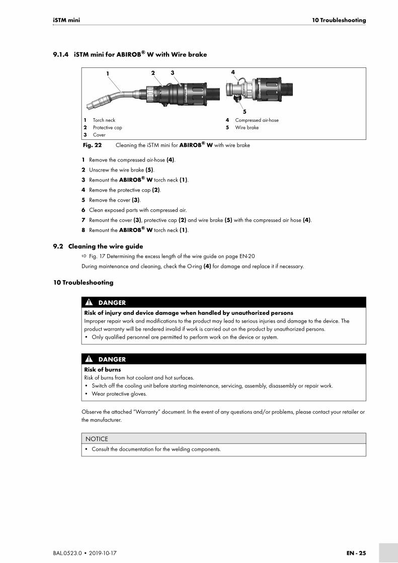
1 Torch neck2 Protective cap
3 Cover4 iSTM mini without torch neck, cover and protective cap
Fig. 21 Cleaning the iSTM mini for ABIROB® W
1 2 3 4
iSTM mini 10 Troubleshooting
BAL.0523.0 • 2019-10-17 EN - 25
9.1.4 iSTM mini for ABIROB® W with Wire brake
1 Remove the compressed air-hose (4).
2 Unscrew the wire brake (5).
3 Remount the ABIROB® W torch neck (1).
4 Remove the protective cap (2).
5 Remove the cover (3).
6 Clean exposed parts with compressed air.
7 Remount the cover (3), protective cap (2) and wire brake (5) with the compressed air hose (4).
8 Remount the ABIROB® W torch neck (1).
9.2 Cleaning the wire guide Fig. 17 Determining the excess length of the wire guide on page EN-20
During maintenance and cleaning, check the O-ring (4) for damage and replace it if necessary.
10 Troubleshooting
Observe the attached “Warranty” document. In the event of any questions and/or problems, please contact your retailer or the manufacturer.
1 Torch neck2 Protective cap3 Cover
4 Compressed air-hose5 Wire brake
Fig. 22 Cleaning the iSTM mini for ABIROB® W with wire brake
1 2 3 4
5
DANGERRisk of injury and device damage when handled by unauthorized personsImproper repair work and modifications to the product may lead to serious injuries and damage to the device. The product warranty will be rendered invalid if work is carried out on the product by unauthorized persons.• Only qualified personnel are permitted to perform work on the device or system.
DANGERRisk of burnsRisk of burns from hot coolant and hot surfaces.• Switch off the cooling unit before starting maintenance, servicing, assembly, disassembly or repair work.• Wear protective gloves.
NOTICE
• Consult the documentation for the welding components.
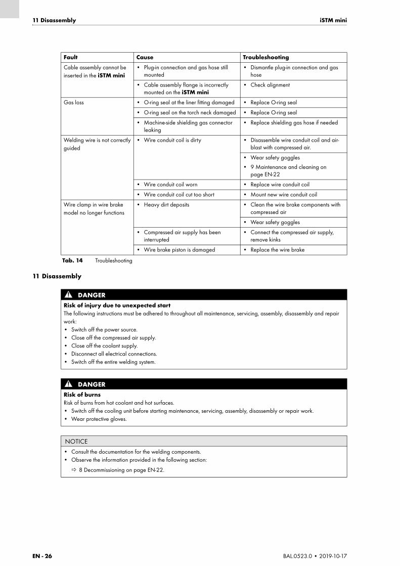
EN - 26 BAL.0523.0 • 2019-10-17
11 Disassembly iSTM mini
11 Disassembly
Fault Cause Troubleshooting
Cable assembly cannot be inserted in the iSTM mini
• Plug-in connection and gas hose still mounted
• Dismantle plug-in connection and gas hose
• Cable assembly flange is incorrectly mounted on the iSTM mini
• Check alignment
Gas loss • O-ring seal at the liner fitting damaged • Replace O-ring seal
• O-ring seal on the torch neck damaged • Replace O-ring seal
• Machine-side shielding gas connector leaking
• Replace shielding gas hose if needed
Welding wire is not correctly guided
• Wire conduit coil is dirty • Disassemble wire conduit coil and air-blast with compressed air.
• Wear safety goggles
• 9 Maintenance and cleaning on page EN-22
• Wire conduit coil worn • Replace wire conduit coil
• Wire conduit coil cut too short • Mount new wire conduit coil
Wire clamp in wire brake model no longer functions
• Heavy dirt deposits • Clean the wire brake components with compressed air
• Wear safety goggles
• Compressed air supply has been interrupted
• Connect the compressed air supply, remove kinks
• Wire brake piston is damaged • Replace the wire brake
Tab. 14 Troubleshooting
DANGERRisk of injury due to unexpected startThe following instructions must be adhered to throughout all maintenance, servicing, assembly, disassembly and repair work:• Switch off the power source.• Close off the compressed air supply.• Close off the coolant supply.• Disconnect all electrical connections.• Switch off the entire welding system.
DANGERRisk of burnsRisk of burns from hot coolant and hot surfaces.• Switch off the cooling unit before starting maintenance, servicing, assembly, disassembly or repair work.• Wear protective gloves.
NOTICE
• Consult the documentation for the welding components.• Observe the information provided in the following section:
8 Decommissioning on page EN-22.

iSTM mini 12 Disposal
BAL.0523.0 • 2019-10-17 EN - 27
1 Disconnect the cable assembly from the wire feeder.
2 Pull out the cable assembly.
3 Disconnect the torch neck and remove it.
6.3 Attaching the ABIROB® G torch neck on page EN-18
6.4 Attaching the ABIROB® W torch neck on page EN-19
6.5 Attaching the wire guide on page EN-20
4 Disassemble the iSTM mini from the robot.
6.2 Maintenance position of the robot on page EN-13
12 DisposalWhen disposing of the system, local regulations, laws, provisions, standards and guidelines must be observed. To correctly dispose of the product, it must first be disassembled.
11 Disassembly on page EN-26
12.1 MaterialsThis product consists for the most part of plastics, steel and nonferrous metals. Steel and nonferrous metals can be molten in steel and iron works and are thus almost infinitely recyclable. The plastic materials used are labeled in preparation for their sorting and separation for later recycling.
12.2 ConsumablesOil, greases and cleaning agents must not contaminate the ground or enter the sewage system. These substances must be stored, transported and disposed of in suitable containers. Observe the relevant local regulations and disposal instructions in the safety data sheets specified by the manufacturer of the consumables. Contaminated cleaning tools (brushes, rags, etc.) must also be disposed of in accordance with the information provided by the consumables’ manufacturer.
12.3 PackagingABICOR BINZEL has reduced the transport packaging to the necessary minimum. The ability to recycle packaging materials is always considered during their selection.
DANGERElectric shockDangerous voltage due to defective cables.• Check all live cables and connections for proper installation and damage.• Replace any damaged, deformed or worn parts.
ZH - 2 BAL.0523.0 • 2019-10-17
iSTM mini
ZH 原厂操作手册中文翻译版
© 厂家保留因印刷错误、不准确信息或产品改良而随时修订此操作手册的权利,
恕不提前通知。新版本操作手册也会涉及到此类更改。
在此操作手册中涉及的商标及注册商标归持有人 / 生产厂家所有。
如想获悉 ABICOR BINZEL 各国代理或合作伙伴的联系信息,请访问我们公司的主页 www.binzel-abicor.com
1 标识 ZH-31.1 标记 ZH-3
2 安全性 ZH-32.1 按规定使用 ZH-32.2 操作者的责任 ZH-42.3 个人防护装备 (PPE) ZH-42.4 警告提示分类 ZH-42.5 紧急情况的说明 ZH-4
3 产品说明 ZH-43.1 技术数据 ZH-53.2 外文缩写 ZH-63.3 铭牌 ZH-73.4 使用的符号和图标 ZH-7
4 供货范围 ZH-84.1 运输 ZH-104.2 存放 ZH-10
5 功能说明 ZH-11
6 开机调试 ZH-116.1 运输和安装 ZH-116.2 机器人保养位置 ZH-126.2.1 将 iSTM mini 固定在机器人上 ZH-136.2.2 安装机器人上的电缆组件 ZH-146.3 固定 ABIROB® G 的枪颈 ZH-186.4 固定 ABIROB® W 的枪颈 ZH-196.5 安装送丝导管 ZH-206.5.1 标准型号 ZH-206.5.2 带夹丝型号 ZH-206.5.3 缩短送丝导管 ZH-21
7 运行 ZH-21
8 停止工作 ZH-21
9 保养和清洁 ZH-229.1 保养周期 ZH-229.1.1 ABIROB® G 适用的 iSTM mini ZH-239.1.2 配备线控制动器的 ABIROB® G 适用的 iSTM mini
ZH-239.1.3 ABIROB® W 适用的 iSTM mini ZH-249.1.4 配备线控制动器的 ABIROB® W 适用的 iSTM mini
ZH-249.2 清洁送丝导管 ZH-24
10 故障及排除方法 ZH-25
11 拆卸 ZH-26
12 废弃处理 ZH-2712.1 材料 ZH-2712.2 辅助材料 ZH-2712.3 包装 ZH-27

iSTM mini 1 标识
BAL.0523.0 • 2019-10-17 ZH - 3
1 标识
配备所属电缆组件的 iSTM mini 机器人固定装置在工业和原材料加工业中用于连接枪颈以及配有中央介质绝
缘套管的机器人。
本操作手册介绍了配合 ABIROB® W 枪颈、 ABIROB® G 枪颈使用的 iSTM mini 机器人固定装置,以及配合
ABIROB® W 和 ABIROB® G 枪颈使用的带夹丝的 iSTM mini 机器人固定装置。该 iSTM mini 只能使用原厂
ABICOR BINZEL 备用件进行操作。
1.1 标记
iSTM mini 机器人固定装置与插图一中所示组件都符合相关欧盟指令的要求。
本产品符合适用的产品上市发布要求。产品上贴有上市要求的所有相应标记。
2 安全性
请注意随附的安全说明资料。
2.1 按规定使用
• 本手册内所描述的设备仅允许用于使用手册内所提到的用途及其方式方法。
同时,请注意运行、保养和维修条件。
• 任何其他用途都视作为不符合使用规定。
• 严禁擅自改装或改进性能。
1 ABIROB® G 焊枪
2 绝缘帽
3 外罩4 iSTM mini
5 电缆组件
6 ABIROB® W 焊枪
7 焊丝夹具1
1仅限有夹丝的型号插图 1 概览
1 2 3 4 5
6
7

ZH - 4 BAL.0523.0 • 2019-10-17
3 产品说明 iSTM mini
2.2 操作者的责任
• 仅允许下述人员操作设备:
• 熟悉基本条例和事故防范;
• 接受过本设备的操作指导;
• 已读完并理解本操作手册;
• 已阅读并理解了随附的“Safety instructions”文档。
• 经过相应培训;
• 能够根据自身专业培训、认知和经验识别潜在危险。
• 在工作区域内不得有其他人员逗留。
• 请遵守相应国家和地区的职业安全规定。
• 请遵守职业安全和事故预防的规定。
2.3 个人防护装备 (PPE)为了防止给使用者带来危险,本手册中推荐穿戴个人防护装备 (PPE)。
• 其中包括防护衣、防护眼镜、 P3 级的呼吸防护面罩、防护手套和安全鞋。
2.4 警告提示分类
此操作手册中使用的警告分为四个等级,按照具有潜在危险的工作步骤加以说明。根据重要程度排列如下:
2.5 紧急情况的说明
在紧急情况下立刻中断下列供给:
• 电气电源
• 压缩空气输送
• 供气
• 冷却液输送
其他措施参见 “ 电源 ” 操作说明或其他外围设备的文件资料。
3 产品说明
危险
指直接面临的危险。如果这些危险不被排除,会致人重伤或死亡。
警告
指可能存在危险的情况。如果不被排除,可能引起重伤。
小心
指可能造成伤害。如果不被排除,可能会引起轻微损伤。
注意
指可能存在影响工作结果或损害设备的危险。
警告
不按规定使用带来的危险
如果不按规定使用,设备可能会危及人员、动物和有形资产。
• 只能按规定使用本设备。
• 切勿擅自改造设备来提高效率,不得进行改动。
• 仅允许具备相应能力的人员对设备或系统进行任何一项作业。
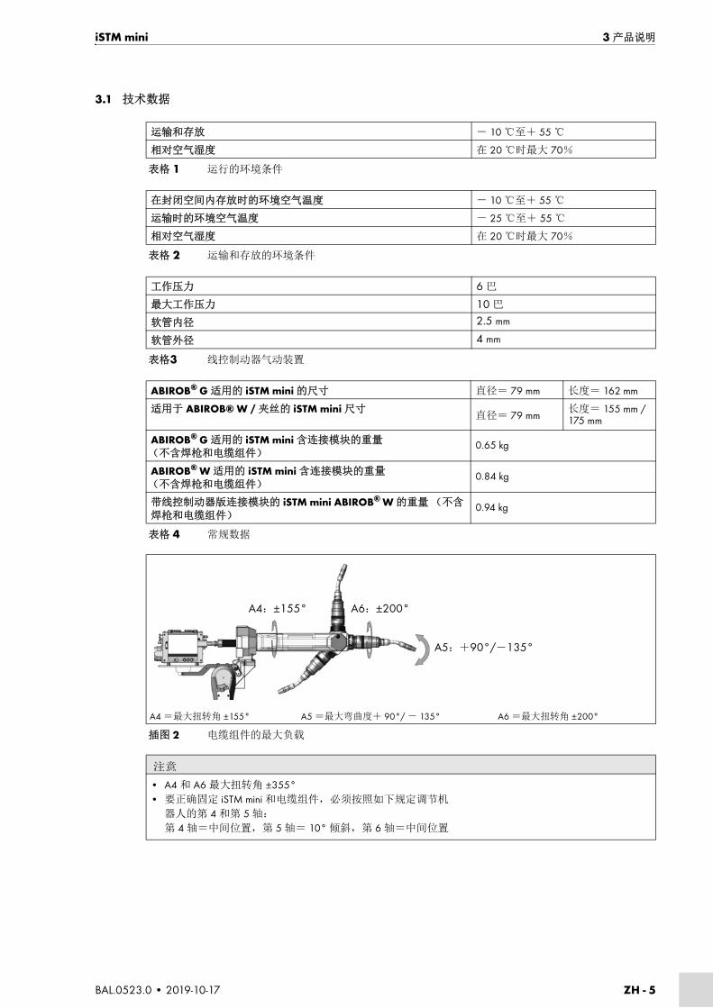
iSTM mini 3 产品说明
BAL.0523.0 • 2019-10-17 ZH - 5
3.1 技术数据
运输和存放 - 10 ℃至+ 55 ℃
相对空气湿度 在 20 ℃时最大 70%
表格 1 运行的环境条件
在封闭空间内存放时的环境空气温度 - 10 ℃至+ 55 ℃
运输时的环境空气温度 - 25 ℃至+ 55 ℃
相对空气湿度 在 20 ℃时最大 70%
表格 2 运输和存放的环境条件
工作压力 6 巴
最大工作压力 10 巴
软管内径 2.5 mm
软管外径 4 mm
表格3 线控制动器气动装置
ABIROB® G 适用的 iSTM mini 的尺寸 直径= 79 mm 长度= 162 mm
适用于 ABIROB® W / 夹丝的 iSTM mini 尺寸直径= 79 mm
长度= 155 mm / 175 mm
ABIROB® G 适用的 iSTM mini 含连接模块的重量(不含焊枪和电缆组件)
0.65 kg
ABIROB® W 适用的 iSTM mini 含连接模块的重量(不含焊枪和电缆组件)
0.84 kg
带线控制动器版连接模块的 iSTM mini ABIROB® W 的重量 (不含焊枪和电缆组件)
0.94 kg
表格 4 常规数据
A4 =最大扭转角 ±155° A5 =最大弯曲度+ 90°/ - 135° A6 =最大扭转角 ±200°
插图 2 电缆组件的最大负载
注意
• A4 和 A6 最大扭转角 ±355°• 要正确固定 iSTM mini 和电缆组件,必须按照如下规定调节机
器人的第 4 和第 5 轴:
第 4 轴=中间位置,第 5 轴= 10° 倾斜,第 6 轴=中间位置
A4:±155° A6:±200°
A5:+90°/-135°

ZH - 6 BAL.0523.0 • 2019-10-17
3 产品说明 iSTM mini
负载数据是在正常条件下测定的,即在反射热量为低到中度、空气自由流通且环境温度约为 28 ℃时测定。
在严苛条件下使用时,必须将负载数据降低 10–20%。
3.2 外文缩写
ABIROB® G ABIROB® W
电压类型 DC
电极的极性 通常是正极
焊丝类型 普通的圆型焊丝
送丝方式 机器送丝
额定电压 141 V 峰值
机器端接头的保护等级(EN 60529) IP3X
保护气(EN ISO 14175) CO2 和 M21
表格 5 焊枪通用数据遵循 EN 60974-7 标准
类型 冷却方式
负载1
1脉冲电弧的负荷数据最多下降 35%
暂载率
焊丝直径 气体流量
有关冷却的说明
冷却功率 流量 流量压力
CO2 M21 最小 最小 最小 最大
ABIROB® A A % mm l/min W l/min bar bar
G350 风冷式 350 300 100 0.8–1.2 约 20 800 约 20 / /
G360 风冷式 360 290 100 0.8–1.6 约 20 800 约 20 / /
G500 风冷式 500 400 100 0.8–1.6 约 20 800 约 20 / /
W300 液冷 330 300 100 0.8–1.2 约 20 800 1.25 1.5 3.5
W500 液冷 550 500 100 0.8–1.6 约 20 800 1.25 1.5 3.5
W600 液冷 600 100 100 0.8–1.6 约 20 800 1.25 1.5 3.5
表格 6 配合 iSTM mini 使用时的焊枪数据(EN 60974-7)
ABIROB® G 风冷式机械化焊枪
ABIROB® W 液冷式机械化焊枪
表格 7 缩写和概念解释

iSTM mini 3 产品说明
BAL.0523.0 • 2019-10-17 ZH - 7
3.3 铭牌
iSTM mini 特征如下:
请注意,所有的回访问询都要提供以下信息:
• 设备型号、设备编号、工厂证明书上的信息
3.4 使用的符号和图标
本操作手册中使用下列符号和图标:
1 绝缘帽 2 外罩 3 商品号 4 设备型号
插图 3 铭牌
1 2 3
4
图标 描述
• 操作指令和计数的符号
交叉引用符号表示详细的、补充或更进一步的信息。
1 文本按顺序引入的操作步骤

ZH - 8 BAL.0523.0 • 2019-10-17
4 供货范围 iSTM mini
4 供货范围
ABIROB® G 适用的 iSTM mini
* 圆柱头螺栓的尺寸和数量取决于机器人类型。
带夹丝的 ABIROB® G 适用的 iSTM mini
1 绝缘帽
2 外罩
3 M4 × 16 圆柱头螺栓
4 连接模块
5 M3 × 5 沉头螺栓
6 前外罩
7 M3 × 6 圆柱头螺栓
8 后外罩
9 iSTM mini
10 M4 × 12 圆柱头螺栓
插图 4 ABIROB® G 适用的 iSTM mini 的供货范围
• iSTM mini 机器人固定装置 • 8 个 M4 × 12 圆柱头螺栓 *
• iSTM mini 电缆组件 • 7 个 M4 × 16 圆柱头螺栓
• 后外罩 • 2 个 M3 × 6 圆柱头螺栓
• 前外罩 • 2 个 M3 × 5 沉头螺栓
• 绝缘帽 • 开口宽度为 11mm 的套筒扳手
• 外罩 • 无硅油 Düsofix 密封油脂 (10g 剂量)
• 螺旋导丝管 • 工厂证明书
• 直型螺旋接头 • 操作手册
• 直径为 6 mm 的保护气体软管
表格 8 ABIROB® G 适用的 iSTM mini 的供货范围
1 2 3 4 5 6 7 8 9
10
1 绝缘帽
2 外罩
3 M4 × 16 圆柱头螺栓
4 连接模块
5 M3 × 5 沉头螺栓
6 前外罩
7 M3 × 6 圆柱头螺栓
8 后外罩
9 iSTM mini
10 M4 × 12 圆柱头螺栓
插图 5 带夹丝的 ABIROB® G 适用的 iSTM mini 型号的供货范围
1 2 3 4 5 6 7 8
9

iSTM mini 4 供货范围
BAL.0523.0 • 2019-10-17 ZH - 9
* 圆柱头螺栓的尺寸和数量取决于机器人类型。
ABIROB® W 适用的 iSTM mini
* 圆柱头螺栓的尺寸和数量取决于机器人类型。
• iSTM mini 机器人固定装置 • 8 个 M4 × 12 圆柱头螺栓 *
• iSTM mini 电缆组件 • 7 个 M4 × 16 圆柱头螺栓
• 后外罩 • 2 个 M3 × 6 圆柱头螺栓
• 前外罩 • 2 个 M3 × 5 沉头螺栓
• 绝缘帽 • 开口宽度为 11 mm 的套筒扳手
• 外罩 • 无硅油 Düsofix 密封油脂 (10 g 剂量)
• 螺旋导丝管 • 工厂证明书
• 直型螺旋接头 • 操作手册
• 直径为 6 mm 的保护气体软管
表格 9 带夹丝的 ABIROB® G 适用的 iSTM mini 型号的供货范围
1 绝缘帽
2 外罩
3 M4 × 16 圆柱头螺栓
4 整套 iCAT mini W CAl
5 iSTM mini
6 M4 × 12 圆柱头螺栓
插图 6 ABIROB® W 适用的 iSTM mini 的供货范围
• iSTM mini 机器人固定装置 • 8 个 M4 × 12 圆柱头螺栓 *
• iSTM mini W 电缆组件 • 7 个 M4 × 16 圆柱头螺栓
• 外罩 • 无硅油 Düsofix 密封油脂 (10 g 剂量)
• 绝缘帽 • 工厂证明书
• 螺旋导丝管 • 操作手册
表格 10 ABIROB® W 适用的 iSTM mini 的供货范围
1 2 3 4 5 6
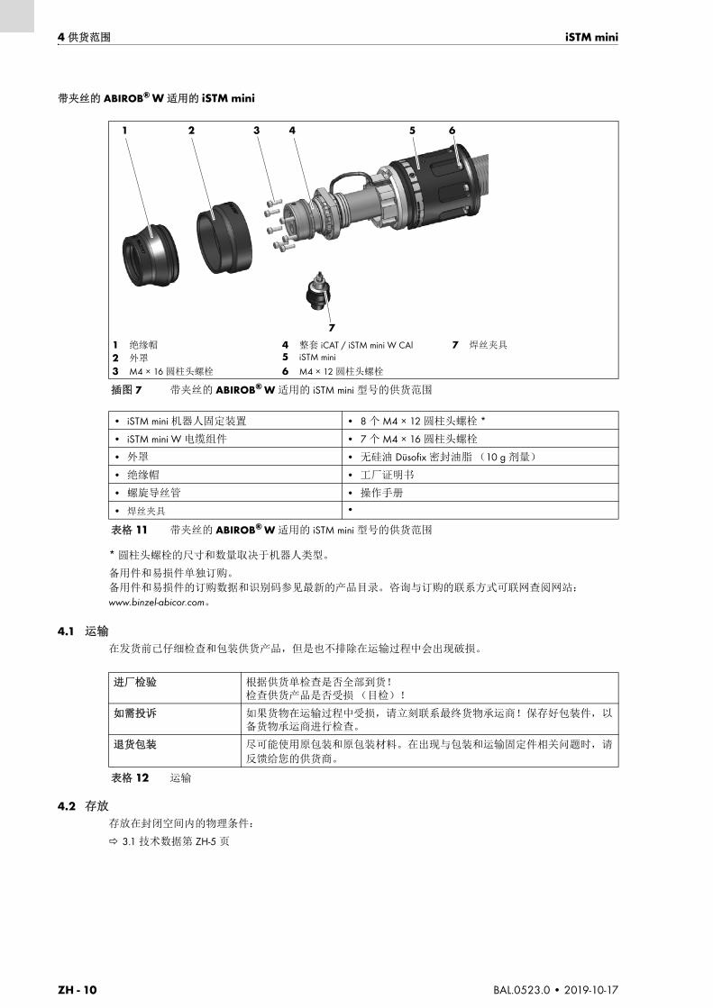
ZH - 10 BAL.0523.0 • 2019-10-17
4 供货范围 iSTM mini
带夹丝的 ABIROB® W 适用的 iSTM mini
* 圆柱头螺栓的尺寸和数量取决于机器人类型。
备用件和易损件单独订购。
备用件和易损件的订购数据和识别码参见最新的产品目录。咨询与订购的联系方式可联网查阅网站:
www.binzel-abicor.com。
4.1 运输
在发货前已仔细检查和包装供货产品,但是也不排除在运输过程中会出现破损。
4.2 存放
存放在封闭空间内的物理条件:
3.1 技术数据第 ZH-5 页
1 绝缘帽
2 外罩
3 M4 × 16 圆柱头螺栓
4 整套 iCAT / iSTM mini W CAl5 iSTM mini
6 M4 × 12 圆柱头螺栓
7 焊丝夹具
插图 7 带夹丝的 ABIROB® W 适用的 iSTM mini 型号的供货范围
• iSTM mini 机器人固定装置 • 8 个 M4 × 12 圆柱头螺栓 *
• iSTM mini W 电缆组件 • 7 个 M4 × 16 圆柱头螺栓
• 外罩 • 无硅油 Düsofix 密封油脂 (10 g 剂量)
• 绝缘帽 • 工厂证明书
• 螺旋导丝管 • 操作手册
• 焊丝夹具 •
表格 11 带夹丝的 ABIROB® W 适用的 iSTM mini 型号的供货范围
1 2 3 4 5 6
7
进厂检验 根据供货单检查是否全部到货!检查供货产品是否受损 (目检)!
如需投诉 如果货物在运输过程中受损,请立刻联系最终货物承运商!保存好包装件,以备货物承运商进行检查。
退货包装 尽可能使用原包装和原包装材料。在出现与包装和运输固定件相关问题时,请
反馈给您的供货商。
表格 12 运输

iSTM mini 5 功能说明
BAL.0523.0 • 2019-10-17 ZH - 11
5 功能说明
iSTM mini 机器人固定装置用于精确固定焊枪的位置,它通过圆柱头螺栓固定在机器人上。
6 开机调试
6.1 运输和安装
危险
存在因意外运行而导致受伤的危险
在整个保养、维护、安装以及拆卸和维修作业过程中必须注意:
• 关闭电源。
• 停止供气。
• 停止冷却液输送。
• 停止压缩空气输送。
• 断开所有电气连接。
• 关闭整个焊接设备。
注意
• 注意下列事项:
3 产品说明第 ZH-4 页
危险
触电
因电缆故障而产生的危险电压。
• 检查所有的导电电缆和接头是否按规定安装以及是否损坏。
• 更换已损坏、变形或磨损的部件。
• 在断电的情况下安装所有部件。
小心
有受伤危险
掉落的装置和组件会导致身体受伤。
• 请选择合适的地点打开包装。
• 请避免突然抬起和放下装置和组件。
• 不能在人员或其他装置上方抬起组件。
• 请直立运输组件。
• 借助合适的辅助工具安装设备。
• 将机器人带到合适的安装位置。
6.2 机器人保养位置第 ZH-12 页
• 注意工作台是否稳固。
• 请穿戴您的个人防护装备:鞋头装有钢帽的安全鞋、防护手套、安全帽、听力保护装置。
• 请将无关人员逐出危险区。
• 注意每一个组件的重量。
3.1 技术数据第 ZH-5 页

ZH - 12 BAL.0523.0 • 2019-10-17
6 开机调试 iSTM mini
6.2 机器人保养位置
小心
电极丝刺入或刺穿
连接气动管线时眼睛受伤。
对于带夹丝的型号,如果管线泄漏或者连接错误,会导致压缩空气溢出,颗粒物可能会因此进入眼睛。
为避免出现这种情况,请按照下列顺序连接:
• 将压缩空气软管连接到夹丝上。
• 连接压缩空气输送装置。
• 请穿戴您的个人防护装备。
小心
倾翻危险
错误安装会导致身体受伤或组件受损。
• 请断开供应管线。
• 请将组件放置在合适的地面上(平坦、稳固、干燥),以防倾翻。
• 请注意最大倾斜角为 10°。
注意
• 保证能够自由使用操作元件和接口。
• 防止组件淋雨和阳光暴晒。
• 只能在干燥、洁净、通风良好的室内使用设备。
注意
• 必须通过机器人靠近保养位置。
• 根据不同的制造商,送丝机的安装也各不相同。为此,请遵守相应送丝机操作手册中的说明。
插图 8 机器人轴概览
J4(A4)
J6(A6)
J5(A5)
+
+
+
-
-
-
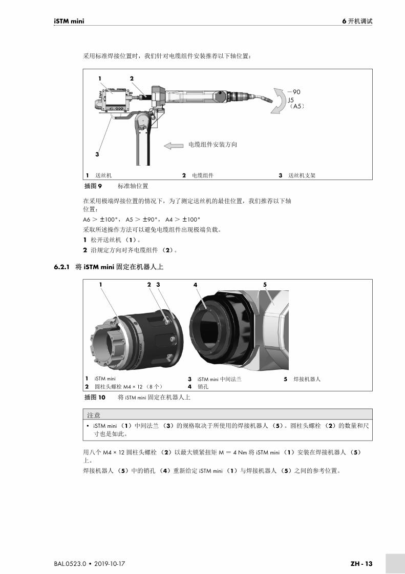
iSTM mini 6 开机调试
BAL.0523.0 • 2019-10-17 ZH - 13
采用标准焊接位置时,我们针对电缆组件安装推荐以下轴位置:
在采用极端焊接位置的情况下,为了测定送丝机的最佳位置,我们推荐以下轴
位置:
A6 > ±100°, A5 > ±90°, A4 > ±100°
采取所述操作方法可以避免电缆组件出现极端负载。
1 松开送丝机(1)。
2 沿规定方向对齐电缆组件(2)。
6.2.1 将 iSTM mini 固定在机器人上
用八个 M4 × 12 圆柱头螺栓(2)以最大锁紧扭矩 M = 4 Nm 将 iSTM mini (1)安装在焊接机器人 (5)上。
焊接机器人(5)中的销孔 (4)重新给定 iSTM mini (1)与焊接机器人 (5)之间的参考位置。
1 送丝机 2 电缆组件 3 送丝机支架
插图 9 标准轴位置
电缆组件安装方向
1
3
2
J5(A5)
-90
1 iSTM mini
2 圆柱头螺栓 M4 × 12 (8 个)
3 iSTM mini 中间法兰
4 销孔
5 焊接机器人
插图 10 将 iSTM mini 固定在机器人上
注意
• iSTM mini (1)中间法兰 (3)的规格取决于所使用的焊接机器人(5)。圆柱头螺栓(2)的数量和尺
寸也是如此。
1 2 3 54

ZH - 14 BAL.0523.0 • 2019-10-17
6 开机调试 iSTM mini
6.2.2 安装机器人上的电缆组件
ABIROB® G 适用的 iSTM mini
1 通过所安装的焊枪联轴器 iSTM mini (7)引入电缆组件(8)。沿安装方向安装电缆组件 (8)。
2 如果已安装,则拆下直型插塞螺旋接头 (10)。
3 用 7 个 M4 × 16 圆柱头螺栓 (2)将电缆组件(8)安装在 iSTM mini(7)上。最大锁紧扭矩
M = 4 Nm。
4 用 2 个 M3 × 6 圆柱头螺栓 (3)将后外罩 (6)安装在 iSTM mini 上。
5 用 2 个符合 DIN 965 标准的 M3 × 5 沉头螺栓 (5)将前外罩(4)安装在电缆组件上。
6 安装 iSTM mini (7)上的外罩。
7 借助旋入助手 (开口宽度 11 mm)拧紧插塞螺旋接头 Ø6。
8 插入保护气体软管并连接保护气体供应装置。
注意
• 安装完成后必须注意位置是否存在泄漏。
• 所有管线(保护气体、压缩空气管道和冷却液软管)的安装不得扭结,且必须保持足够间隙。
警告
有受伤危险
快速旋转的部件会致人重伤。
• 在用压缩空气吹扫时须穿戴适当的防护装备,特别是要戴上护目镜。
1 外罩
2 M4 × 16 圆柱头螺栓
(7 个)
3 M3 × 6 圆柱头螺栓
(2 个)
4 前外罩
5 M3 × 5 沉头螺栓
(2 个)
6 后外罩7 iSTM mini
8 电缆组件
9 机器端接头
10 插塞螺旋接头 Ø6/G1/8"11 旋入助手
(开口宽度 11 mm)12 直径为 6 mm 的保护气体软管
插图 11 安装电缆组件 ABIROB® G 适用的 iSTM mini
注意
• 焊接电流接头必须与送丝机相连。
送丝机的操作手册。
安装方向
1 2 3 4 5 6 7 8
9
10
1112

iSTM mini 6 开机调试
BAL.0523.0 • 2019-10-17 ZH - 15
带夹丝的 ABIROB® G 适用的 iSTM mini
1 通过所安装的焊枪联轴器 iSTM mini (7)引入电缆组件 (8)。沿安装方向安装电缆组件 (8)。
2 如果已安装,则拆下直型插塞螺旋接头(10)。
3 用 7 个 M4 × 16 圆柱头螺栓(2)将电缆组件 (8)安装在 iSTM mini(7)上。最大锁紧扭矩 M =
4 Nm。
4 用 2 个 M3 × 6 圆柱头螺栓(3)将后外罩安装在 iSTM mini (7)上。
5 将焊丝夹具(4)的压缩空气输送用软管 (5)穿过后外罩(6)的开口。
6 安装 iSTM mini (7)上的外罩。
7 安装焊丝夹具(4)。
8 借助旋入助手(开口宽度 11 mm)拧紧插塞螺旋接头 Ø6。
9 插入保护气体软管并连接保护气体供应装置。
1 外罩
2 M4 × 16 圆柱头螺栓
(7 个)
3 M3 × 6 圆柱头螺栓(2 个)
4 焊丝夹具
5 压缩空气输送用软管
6 后外罩7 iSTM mini
8 电缆组件
9 机器端接头
10 插塞螺旋接头 Ø6/G1/8"11 旋入助手
(开口宽度 11 mm)12 直径为 6 mm 的保护气体软管
插图 12 安装电缆组件 — 带夹丝的 ABIROB® G 适用的 iSTM mini
注意
• 焊接电流接头必须与送丝机相连。
送丝机操作手册。
安装方向
1 2 3 4 5 6 7 8
10
1112
9

ZH - 16 BAL.0523.0 • 2019-10-17
6 开机调试 iSTM mini
ABIROB® W 适用的 iSTM mini
1 通过所安装的焊枪联轴器 iSTM mini (5)引入电缆组件(4)。沿安装方向安装电缆组件 (4)。
2 用 7 个 M4 × 16 圆柱头螺栓 (3)将电缆组件(4)安装在 iSTM mini (5)上。最大锁紧扭矩 M =
4 Nm。
3 安装 iSTM mini (5)上的外罩 (2)和绝缘帽(1)。
4 插入保护气体软管 (7)并连接保护气体供应装置。
5 连接冷却液管线 (6)。
1 绝缘帽
2 外罩
3 M4 × 16 圆柱头螺栓 (7 个)
4 电缆组件5 iSTM mini
6 冷却液管线(红色+蓝色)
7 直径为 6 mm 的保护气体软管
插图 13 安装电缆组件 ABIROB® W 适用的 iSTM mini
安装方向
1 2 3 4 5
6
7

iSTM mini 6 开机调试
BAL.0523.0 • 2019-10-17 ZH - 17
带夹丝的 ABIROB® W 适用的 iSTM mini
1 通过所安装的焊枪联轴器iSTM mini (8) 引入电缆组件 (6)。沿安装方向安装电缆组件 (8)。
2 用7个M4 × 16圆柱头螺栓 (8) 将电缆组件 (3) 安装在iSTM mini (6) 上。
最大锁紧扭矩M=4 Nm。
3 安装iSTM mini (2)上的外罩 (1) 和绝缘帽 (6)。
4 穿过绝缘帽中的孔 (1) 导入压缩空气软管 (5)。
5 穿过绝缘帽中的孔 (1) 拧入焊丝夹具 (11) 并连接压缩空气软管 (5)。
6 插入保护气体软管 (10) 并连接保护气体供应装置。
7 将压缩空气软管 (5) 连接至压缩空气供应装置(无插图)。
8 连接冷却液管线 (9)。
连接冷却液
首次开机调试时或更换电缆组件后,必须对整个冷却系统排气:执行下述操作:
1 将冷却液软管从循环冷却器上松开,将冷却液接头从电源松开,通过收集容器排气。
2 盖住冷却液回流软管上的开口,然后反复突然重新打开开口,直至有持续且无气泡的冷却液流流入收集
容器内。
3 关闭循环冷却器并重新连接冷却液回流软管。
1 绝缘帽
2 外罩
3 M4 × 16 圆柱头螺栓
(7 个)
4 整套 iCAT / iSTM mini W CAl
5 压缩空气输送用软管6 iSTM mini
7 M4 × 12 圆柱头螺栓
8 电缆组件
9 冷却液管线
(红色+蓝色)
10 直径为 6 mm的保护气体软管
11 焊丝夹具
插图 14 安装电缆组件 — 带夹丝的 ABIROB® W 适用的 iSTM mini
1 2 3 4 5 6 7 8
91011
安装方向
警告
烧伤
如在无冷却液或冷却液流量过小时进行焊接,焊枪可能过热。
• 戴上相应的防护手套。
• 定期检查冷却液液位。
注意
• 注意:按规定安装冷却液输入管和回流管。冷却液始流管=蓝色,冷却液回流管=红色
• 切勿使用去离子水或软化水作为冷却液或用于检测密封性和流量。
这可能会影响焊枪的使用寿命。
• 我们建议,使用 BTC 系列的 ABICOR BINZEL 冷却液来冷却液冷式焊枪。
请注意相对应的安全数据表。
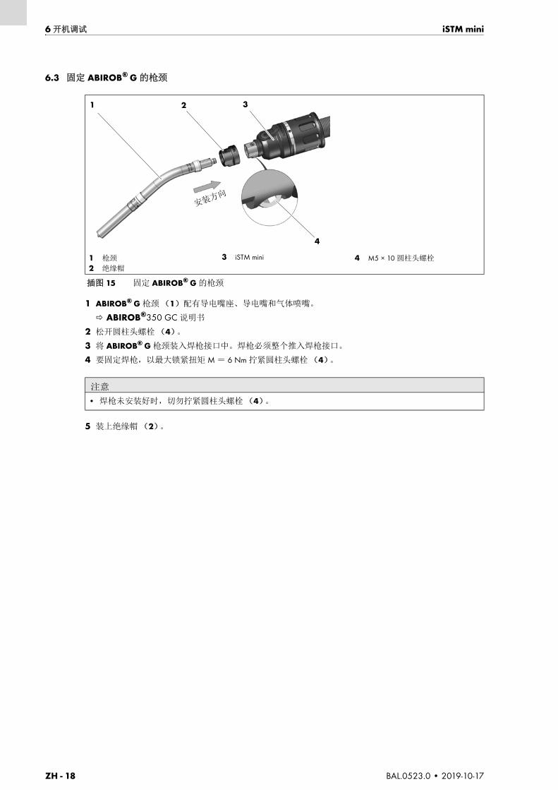
ZH - 18 BAL.0523.0 • 2019-10-17
6 开机调试 iSTM mini
6.3 固定 ABIROB® G 的枪颈
1 ABIROB® G 枪颈(1)配有导电嘴座、导电嘴和气体喷嘴。
ABIROB®350 GC 说明书
2 松开圆柱头螺栓 (4)。
3 将 ABIROB® G 枪颈装入焊枪接口中。焊枪必须整个推入焊枪接口。
4 要固定焊枪,以最大锁紧扭矩 M = 6 Nm 拧紧圆柱头螺栓(4)。
5 装上绝缘帽 (2)。
1 枪颈
2 绝缘帽
3 iSTM mini 4 M5 × 10 圆柱头螺栓
插图 15 固定 ABIROB® G 的枪颈
注意
• 焊枪未安装好时,切勿拧紧圆柱头螺栓(4)。
1 2 3
4
安装方向

iSTM mini 6 开机调试
BAL.0523.0 • 2019-10-17 ZH - 19
6.4 固定 ABIROB® W 的枪颈
1 ABIROB® W 枪颈(1)配有导电嘴座、导电嘴和气体喷嘴。
2 将定位销(3)插入标记的钻孔中。
ABIROB® W 枪颈(1)只能固定在此位置。
3 将 ABIROB® W 枪颈用固定螺母 (2)拧紧固定在 iSTM mini (4)的接口上。
1 枪颈
2 固定螺母
3 定位销 4 iSTM mini
插图 16 固定 ABIROB® W 的枪颈
注意
• 焊枪在多次使用之后可能会出现无法用手松开的情况。使用合适的螺帽扳手松开。
• 不得使用钳子松开焊枪。
1 2 3
4安装方向

ZH - 20 BAL.0523.0 • 2019-10-17
6 开机调试 iSTM mini
6.5 安装送丝导管
6.5.1 标准型号
1 给电缆组件装备枪颈和易损件。
2 将送丝导管插入电缆组件至止挡处。
3 测定超出长度 a (2)。
4 从正面将送丝导管缩短 a (2)。缩短送丝导管,使其在安装完成后稍微拉长。
5 将送丝导管插入电缆组件至止挡处,并用 M4 × 5 定位螺钉 (3)固定。
注意以下事项:
9.2 清洁送丝导管第 ZH-24 页
6.5.2 带夹丝型号
带夹丝型号用的枪颈必须装备一个专用的枪颈导丝管。
注意
• 新的尚未使用过的送丝导管必须缩短到软管组件的实际长度。
• 每次更换送丝导管(螺旋导丝管 / 塑料送丝管)时,请注意随附说明书中的产品信息。
• 缩短之后,将焊枪端的送丝导管剥皮 15 mm。
1 衬套
2 超出长度 a3 定位螺钉 ISO 4027 – M4 × 5 4 O 形环
插图 17 测定送丝导管的超出长度
注意
• 本章中送丝导管的安装包含一个定位螺钉(3)。其他机器接头并不包含。
1 2a 3
4
注意
• 新的尚未使用过的送丝导管必须缩短到软管组件的实际长度。
• 每次更换送丝导管(螺旋导丝管 / 塑料送丝管)时,请注意随附说明书中的产品信息。
• 缩短之后,将焊枪端的送丝导管剥皮 15 mm。

iSTM mini 7 运行
BAL.0523.0 • 2019-10-17 ZH - 21
6.5.3 缩短送丝导管
插图 17 测定送丝导管的超出长度第 ZH-20 页
1 给电缆组件装备枪颈和易损件。
2 将送丝导管插入电缆组件至止挡处。
3 测定超出长度 a (2)。
4 从正面将送丝导管缩短 a (2)。缩短送丝导管,使其在安装完成后稍微拉长。
5 将送丝导管插入电缆组件至止挡处,并用 M4 × 5 定位螺钉(3)固定。
7 运行
由于 iSTM mini 已接入焊枪的焊接过程,相应焊枪和所使用焊接电源调试完毕后即执行操作步骤。为此,请
遵守相应焊枪操作手册中的说明。
8 停止工作
停止工作取决于相应的焊枪。
为此,请遵守相应焊枪及焊接电源操作手册中的说明。
插图 18 缩短送丝导管
注意
• 如果剥皮的送丝导管直径超过 5 mm,则必须在缩短后将焊枪端的送丝导管剥皮 15 mm。• 未剥皮导丝管的直径不得超过 Ø 5 mm。
15 mm
≤5
mm
≥5
mm
警告
电击。烧伤。
熔融的部件飞溅。
• 会导致接触焊枪时触电。电弧会灼伤眼球和引起烧伤。
• 请使用符合 BGV D1 要求的合适的防护装备,以避免出现可导致接触载流部件的电气脱扣,以及设立焊
接站点带来的影响。
小心
滑倒、绊倒和跌倒。
进入机器人工作室时,可能会出现因残余焊丝或润滑剂滑倒的情况。
• 请使用合适的防护装备加以避免。
• 请穿戴您的个人防护装备。
注意
• 注意各焊接组件的操作手册。
注意
• 请确保在停止操作前,严格遵循焊接组件的关闭程序。
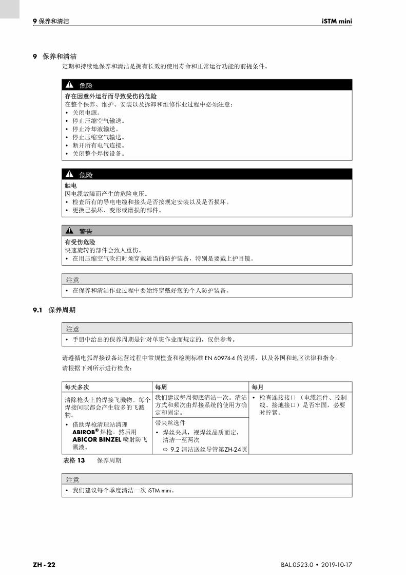
ZH - 22 BAL.0523.0 • 2019-10-17
9 保养和清洁 iSTM mini
9 保养和清洁
定期和持续地保养和清洁是拥有长效的使用寿命和正常运行功能的前提条件。
9.1 保养周期
请遵循电弧焊接设备运营过程中常规检查和检测标准 EN 60974-4 的说明,以及各国和地区法律和指令。
请根据下列所示进行检查:
危险
存在因意外运行而导致受伤的危险
在整个保养、维护、安装以及拆卸和维修作业过程中必须注意:
• 关闭电源。
• 停止压缩空气输送。
• 停止冷却液输送。
• 停止压缩空气输送。
• 断开所有电气连接。
• 关闭整个焊接设备。
危险
触电
因电缆故障而产生的危险电压。
• 检查所有的导电电缆和接头是否按规定安装以及是否损坏。
• 更换已损坏、变形或磨损的部件。
警告
有受伤危险
快速旋转的部件会致人重伤。
• 在用压缩空气吹扫时须穿戴适当的防护装备,特别是要戴上护目镜。
注意
• 在保养和清洁作业过程中要始终穿戴好您的个人防护装备。
注意
• 手册中给出的保养周期是针对单班作业而规定的,仅供参考。
每天多次 每周 每月
清除枪头上的焊接飞溅物。每个焊接间隙都会产生较多的飞溅物。
• 借助焊枪清理站清理ABIROB® 焊枪。然后用ABICOR BINZEL 喷射防飞溅液。
我们建议每周彻底清洁一次。清洁方式和频次由焊接系统的使用方确定和固定。
• 检查连接接口(电缆组件、控制线、接地接口)是否牢固,必要时拧紧。
带夹丝选件
• 焊丝夹具,视焊丝品质而定,清洁一至两次
9.2 清洁送丝导管第ZH-24页
表格 13 保养周期
注意
• 我们建议每个季度清洁一次 iSTM mini。

iSTM mini 9 保养和清洁
BAL.0523.0 • 2019-10-17 ZH - 23
9.1.1 ABIROB® G 适用的 iSTM mini
1 取下绝缘帽(1)。
2 取下枪颈上的外罩(2)。
3 用压缩空气吹扫裸露的部件。
4 重新装上外罩(2)和绝缘帽 (1)。
9.1.2 配备线控制动器的 ABIROB® G 适用的 iSTM mini
1 松开压缩空气软管(5)。
2 旋下焊丝夹具(4)。
3 取下绝缘帽(1)。
4 取下枪颈上的外罩(2)。
5 用压缩空气吹扫裸露的部件。
6 重新装上外罩(2)、绝缘帽(1)和焊丝夹具 (4)及压缩空气软管(5)。
1 绝缘帽 2 外罩 3 无绝缘帽和外罩的 iSTM mini
插图 19 ABIROB® G 适用的 iSTM mini 的清洁
1 2 3
1 绝缘帽
2 外罩
3 无绝缘帽和外罩的 iSTM mini 4 焊丝夹具
5 压缩空气软管
插图 20 带夹丝的 ABIROB® G 适用 iSTM mini 的清洁
1 2 3 4 5

ZH - 24 BAL.0523.0 • 2019-10-17
9 保养和清洁 iSTM mini
9.1.3 ABIROB® W 适用的 iSTM mini
1 取下 ABIROB® W 枪颈 (1)。
2 取下绝缘帽 (2)以及外罩(3)。
3 用压缩空气吹扫无焊枪、外罩和绝缘帽 (4)的 iSTM mini 上裸露的部件。
4 装上外罩 (3)和绝缘帽(2)。
5 重新装上 ABIROB® W 枪颈 (1)。
9.1.4 配备线控制动器的ABIROB® W适用的iSTM mini
1 松开压缩空气软管 (4)。
2 旋下焊丝夹具 (5)。
3 取下ABIROB® W枪颈(1)。
4 取下绝缘帽(2)以及外罩(3)。
5 用压缩空气吹扫裸露的部件。
6 重新装上外罩(3)、绝缘帽(2)和焊丝夹具(5)及压缩空气软管(4)。
7 重新装上ABIROB® W枪颈(1)。
9.2 清洁送丝导管
插图 17 测定送丝导管的超出长度第 ZH-20 页
在保养和清洁周期检查 O 形环 (4)是否受损,必要时更换。
1 枪颈
2 绝缘帽
3 外罩 4 无枪颈、外罩和绝缘帽的 iSTM mini
插图 21 ABIROB® W 适用 iSTM mini 的清洁
1 2 3 4
1 枪颈2 绝缘帽
3 外罩
4 压缩空气软管
5 焊丝夹具
插图 22 带夹丝的 ABIROB® W 适用 iSTM mini 的清洁
1 2 3 4
5
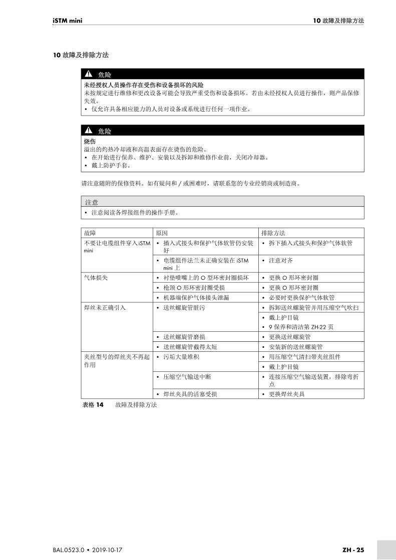
iSTM mini 10 故障及排除方法
BAL.0523.0 • 2019-10-17 ZH - 25
10 故障及排除方法
请注意随附的保修资料。如有疑问和 / 或困难时,请联系您的专业经销商或制造商。
危险
未经授权人员操作存在受伤和设备损坏的风险
未按规定进行维修和更改设备可能会导致严重受伤和设备损坏。若由未经授权人员进行操作,则产品保修
失效。
• 仅允许具备相应能力的人员对设备或系统进行任何一项作业。
危险
烧伤
溢出的灼热冷却液和高温表面存在烫伤的危险。
• 在开始进行保养、维护、安装以及拆卸和维修作业前,关闭冷却器。
• 戴上防护手套。
注意
• 注意阅读各焊接组件的操作手册。
故障 原因 排除方法
不要让电缆组件穿入 iSTM mini
• 插入式接头和保护气体软管仍安装好
• 拆下插入式接头和保护气体软管
• 电缆组件法兰未正确安装在 iSTM mini 上
• 注意对齐
气体损失 • 衬垫喷嘴上的 O 型环密封圈损坏 • 更换 O 形环密封圈
• 枪颈 O 形环密封圈受损 • 更换 O 形环密封圈
• 机器端保护气体接头泄漏 • 必要时更换保护气体软管
焊丝未正确引入 • 送丝螺旋管脏污 • 拆卸送丝螺旋管并用压缩空气吹扫
• 戴上护目镜
• 9 保养和清洁第 ZH-22 页
• 送丝螺旋管磨损 • 更换送丝螺旋管
• 送丝螺旋管截得太短 • 安装新的送丝螺旋管
夹丝型号的焊丝夹不再起
作用
• 污垢大量堆积 • 用压缩空气清扫带夹丝组件
• 戴上护目镜
• 压缩空气输送中断 • 连接压缩空气输送装置,排除弯折点
• 焊丝夹具的活塞受损 • 更换焊丝夹具
表格 14 故障及排除方法
ZH - 26 BAL.0523.0 • 2019-10-17
11 拆卸 iSTM mini
11 拆卸
1 从送丝机松开软管组件。
2 拉出电缆组件。
3 松开并取下枪颈。
6.3 固定 ABIROB® G 的枪颈第 ZH-18 页
6.4 固定 ABIROB® W 的枪颈第 ZH-19 页
6.5 安装送丝导管第 ZH-20 页
4 将 iSTM mini 从机器人中取下。
6.2 机器人保养位置第 ZH-12 页
危险
存在因意外运行而导致受伤的危险
在整个保养、维护、安装以及拆卸和维修作业过程中必须注意:
• 关闭电源。
• 停止压缩空气输送。
• 停止冷却液输送。
• 断开所有电气连接。
• 关闭整个焊接设备。
危险
烧伤
溢出的灼热冷却液和高温表面存在烫伤的危险。
• 在开始进行保养、维护、安装以及拆卸和维修作业前,关闭冷却器。
• 戴上防护手套。
注意
• 注意各焊接组件的操作手册。
• 请注意下列章节内的信息:
8 停止工作第 ZH-21 页。
危险
触电
因电缆故障而产生的危险电压。
• 检查所有的导电电缆和接头是否按规定安装以及是否损坏。
• 更换已损坏、变形或磨损的部件。

iSTM mini 12 废弃处理
BAL.0523.0 • 2019-10-17 ZH - 27
12 废弃处理
在进行废弃处理时,请遵守当地规定、法律、法规、规范和指令。要按规定处置该产品,必须先进行拆卸。
11 拆卸第 ZH-26 页
12.1 材料
本产品大部分由塑料、钢材和有色金属组成。钢材和有色金属可以在钢厂和冶炼厂重新熔融,因此几乎可以
无限回收利用。所用的塑料都对材料进行了分类和分级的标记,以备以后回收利用。
12.2 辅助材料
严禁油、润滑脂和清洁剂流入土壤以及下水道。必须将上述物质放在合适的容器里保存、运输和废弃处理。
同时,请注意相应的本地规定以及由辅助材料生产商给定的安全数据表中有关废弃处理的提示。同样,污染
的清洁工具(刷子、抹布等)也必须按照辅助材料生产商的说明废弃处理。
12.3 包装
ABICOR BINZEL 采用最为精简的运输包装,尽可能地选用可回收利用的包装材料。

JA - 2 BAL.0523.0 • 2019-10-17
iSTM mini
JA 取扱説明書の原本の翻訳
© 本取扱説明書に印刷誤植があったり、不正確な情報が記載されていたり、或いは製品の改良があ
る場合、当社は事前の予告なしに説明書を変更する権利を有します。変更がある場合は取扱説明書
の新しい版で反映されます。
この取扱説明書のストアブランドおよび商標はすべて各保有者および製造者に所有権があります。
ABICOR BINZEL の各国代理店またはパートナーの連絡先情報または弊社の販売中の製品に関する
ドキュメントを入手するには、弊社の ホームページ www.binzel-abicor.com をご覧ください。
1 概要 JA-31.1 認証マーク JA-3
2 安全 JA-32.1 正しい使用方法 JA-32.2 操作者の義務 JA-42.3 作業者用保護具(PPE) JA-42.4 警告の分類 JA-42.5 緊急時の対応 JA-4
3 製品について JA-53.1 仕様 JA-53.2 略語 JA-63.3 ネームプレート JA-73.4 使用記号とシンボル JA-7
4 同梱品 JA-84.1 輸送 JA-124.2 保管 JA-12
5 機能説明 JA-12
6 試運転 JA-126.1 移動と設置 JA-126.2 ロボットのメンテナンス位置 JA-146.2.1 iSTM mini のロボットへの固定 JA-156.2.2 ケーブルアッセンブリをロボッ
トに取付 JA-156.3 トーチネック、ABIROB® G の固定 JA-206.4 トーチネック ABIROB® W の固定 JA-216.5 ワイヤーガイドの取付 JA-226.5.1 基準仕様品 JA-226.5.2 ワイヤブレーキ仕様品 JA-226.5.3 ワイヤーガイドの短縮 JA-23
7 運転 JA-23
8 運転終了 JA-24
9 整備と清掃 JA-249.1 保守の間隔 JA-259.1.1 iSTM mini、ABIROB® G 用 JA-259.1.2 iSTM mini、ワイヤブレーキ搭載
ABIROB® G 用 JA-269.1.3 iSTM mini、ABIROB® W 用 JA-269.1.4 iSTM mini、ワイヤブレーキ搭載
ABIROB® W 用 JA-279.2 ワイヤーガイドの清掃 JA-27
10 故障と対策 JA-27
11 分解 JA-28
12 廃棄 JA-2912.1 材料 JA-2912.2 補助材料 JA-2912.3 梱包 JA-29

iSTM mini 1 概要
BAL.0523.0 • 2019-10-17 JA - 3
1 概要
ロボットマウント iSTM mini にはケーブルアッセンブリが付属し、工業・産業部門で中央に媒体導管のあ
るトーチネックとロボットの結合用に使用されます。
本取扱説明書には、ロボットマウント iSTM mini を溶接トーチネック ABIROB® W および溶接トーチネッ
ク ABIROB® G と、またワイヤブレーキ搭載 iSTM mini を溶接トーチ ABIROB® W および ABIROB® G と組
み合わせて使用する際の説明を記載しています。
iSTM mini をお使いになる際は必ず純正 ABICOR BINZEL スペアパーツをご使用ください。
1.1 認証マーク
ロボットマウント iSTM mini は、図 1 に示されたコンポーネントと合わせて関連する EU 規定要件を満た
します。
本製品は各市場での流通に必要な適用要件を満たしています。対応する必要な認証マークは製品に取り付
けられています。
2 安全
添付文書の安全の手引きに従ってください。
2.1 正しい使用方法
• この説明書に記載されている装置は、この説明書に記載されている目的と方法でのみ使用してくださ
い。操作・メンテナンス・修理の際は本書を参照してください。
• その他のいかなる使用も規定に違反したものとみなされます。
• 性能向上を目的とした自己判断での改造や変更は認められていません。
1 溶接トーチ
ABIROB® G2 保護キャップ
3 カバー
4 iSTM mini5 ケーブルアッセンブリ
6 溶接トーチ ABIROB® W7 ワイヤクランプ装置1
1 ワイヤブレーキの付いた仕様品のみ図1 概要
1 2 3 4 5
6
7

JA - 4 BAL.0523.0 • 2019-10-17
2 安全 iSTM mini
2.2 操作者の義務
• 装置の取扱いは必ず、
• 基礎となる規定および事故防止について熟知し、
• 装置の取扱いについて研修を受け、
• 本取扱説明書を読んだ上で理解し、
• 添付文書「Safety instructions」を読んで理解している;
• 相応する教育を受け、
• 専門的な教育、知識および経験に基づいて、想定されうる危険を検知できる者のみ行ってください。
• 他の人を作業領域に近づけないようにしてください。
• 各国の作業安全規定に従ってください。
• 作業安全及び事故防止規定を遵守してください。
2.3 作業者用保護具(PPE)使用者の安全を守るため、本説明書では作業用保護具(PPE)の着用を推奨しています。
• これは保護衣、保護メガネ、P3 クラスの呼吸保護マスク、保護手袋および安全靴で構成されています。
2.4 警告の分類
取扱説明書で使用する警告は、4 つの異なるレベルに分類されており、考えられる危険な作業工程を示し
ています。これらの意味を重要度が高い順に説明します:
2.5 緊急時の対応
緊急時には、ただちに次のユーティリティを停止してください。
• 電気的な電源供給
• 圧縮空気供給
• ガス供給
• 冷却剤供給
そのほかの対策については、取扱説明書の「電源」の項目や、そのほかの周辺機器の資料をご覧くださ
い。
危険
差し迫っている危険を示しています。これが避けられない場合、死亡あるいは重傷につながります。
警告
起こりうる危険状況を示しています。これが避けられない場合、重傷につながることがあります。
注意
起こりうる有害状況を示しています。これが避けられない場合、軽傷または微傷を引き起こすおそれが
あります。
予告
作業結果が損なわれたり、機器の物的損害が引き起こされたりするおそれのある危険を表します。
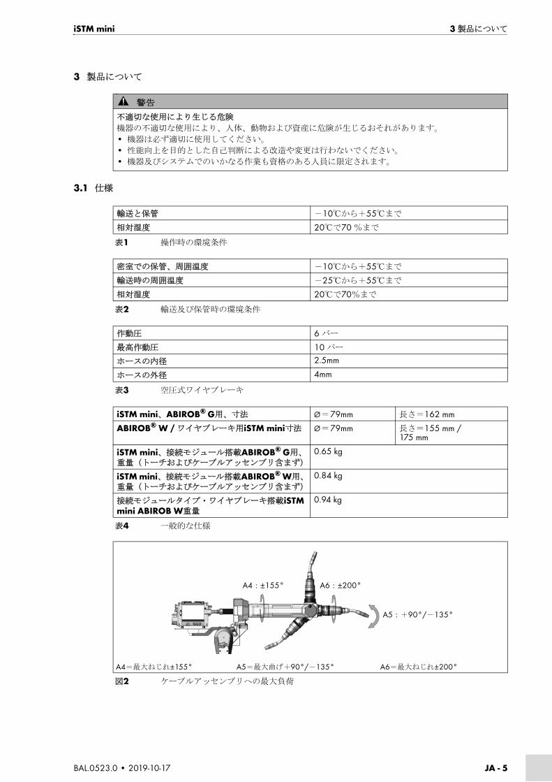
iSTM mini 3 製品について
BAL.0523.0 • 2019-10-17 JA - 5
3 製品について
3.1 仕様
警告
不適切な使用により生じる危険
機器の不適切な使用により、人体、動物および資産に危険が生じるおそれがあります。
• 機器は必ず適切に使用してください。
• 性能向上を目的とした自己判断による改造や変更は行わないでください。
• 機器及びシステムでのいかなる作業も資格のある人員に限定されます。
輸送と保管 -10℃から+55℃まで
相対湿度 20℃で70 %まで
表1 操作時の環境条件
密室での保管、周囲温度 -10℃から+55℃まで
輸送時の周囲温度 -25℃から+55℃まで
相対湿度 20℃で70%まで
表2 輸送及び保管時の環境条件
作動圧 6 バー
高作動圧 10 バー
ホースの内径 2.5mm
ホースの外径 4mm
表3 空圧式ワイヤブレーキ
iSTM mini、ABIROB® G用、寸法 Ø = 79mm 長さ=162 mm
ABIROB® W / ワイヤブレーキ用iSTM mini寸法 Ø = 79mm 長さ=155 mm / 175 mm
iSTM mini、接続モジュール搭載ABIROB® G用、重量(トーチおよびケーブルアッセンブリ含まず)
0.65 kg
iSTM mini、接続モジュール搭載ABIROB® W用、重量(トーチおよびケーブルアッセンブリ含まず)
0.84 kg
接続モジュールタイプ・ワイヤブレーキ搭載iSTM mini ABIROB W重量
0.94 kg
表4 一般的な仕様
A4= 大ねじれ±155° A5= 大曲げ+90°/-135° A6= 大ねじれ±200°
図2 ケーブルアッセンブリへの 大負荷
A4:±155° A6:±200°
A5:+90°/-135°

JA - 6 BAL.0523.0 • 2019-10-17
3 製品について iSTM mini
負荷データは、通常の条件、低度~中度の反射熱、自由通気状態および周囲温度約 28 ℃下で記録された
ものです。厳しい条件下で使用する場合、負荷データは 10 ~ 20%減少します。
3.2 略語
予告
• Torsion A4 + A6 における 大捻りは max±355° です。
• iSTM mini 及びケーブルアッセンブリを適切に艤装するには、ロボットの 4 軸と 5 軸を以下のように
設定します。
4 軸=中心位置 ±0° 5軸=+ 10° 6軸=中心位置 ±0°
ABIROB® G ABIROB® W
電源 DC
電極の極性 通常はプラス電極+
ワイヤタイプ 市販の丸ワイヤ
ガイド 自動機用
定格電圧 ピーク電圧141 V
機械側のコネクタの保護等級(EN 60529) IP3X
シールドガス(EN ISO 14175) CO2とM21
表5 EN 60974-7による一般的なトーチの仕様
タイプ 冷却方式
負荷1
1パルスアーク溶接の場合、電流負荷は 大35%減少します
使用率
ワイヤ-Ø ガス流量
冷却データ
冷却出力 流量 送水圧力
CO2 M21 低 低 低 高
ABIROB® A A % mm ℓ/min W ℓ/min bar bar
G350 空冷 350 300 100 0.8–1.2 約20 800 約20 / /
G360 空冷 360 290 100 0.8–1.6 約20 800 約20 / /
G500 空冷 500 400 100 0.8–1.6 約20 800 約20 / /
W300 水冷 330 300 100 0.8–1.2 約20 800 1.25 1.5 3.5
W500 水冷 550 500 100 0.8–1.6 約20 800 1.25 1.5 3.5
W600 水冷 600 100 100 0.8–1.6 約20 800 1.25 1.5 3.5
表6 iSTM miniに装着可能なトーチデータ(EN 60974-7)
ABIROB® G ロボット及び自動機用空冷溶接トーチ
ABIROB® W 機械制御式溶接トーチ、液冷
表7 略語および用語の説明
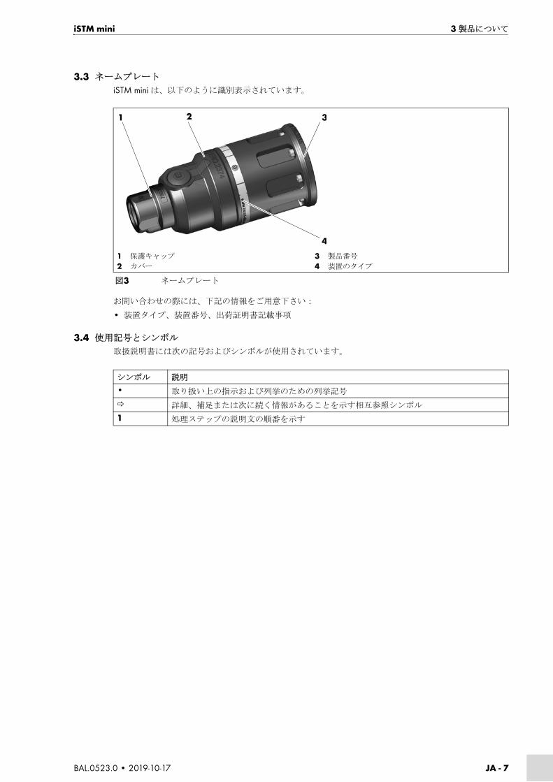
iSTM mini 3 製品について
BAL.0523.0 • 2019-10-17 JA - 7
3.3 ネームプレート
iSTM mini は、以下のように識別表示されています。
お問い合わせの際には、下記の情報をご用意下さい:
• 装置タイプ、装置番号、出荷証明書記載事項
3.4 使用記号とシンボル
取扱説明書には次の記号およびシンボルが使用されています。
1 保護キャップ
2 カバー
3 製品番号
4 装置のタイプ
図3 ネームプレート
1 2 3
4
シンボル 説明
• 取り扱い上の指示および列挙のための列挙記号
詳細、補足または次に続く情報があることを示す相互参照シンボル
1 処理ステップの説明文の順番を示す

JA - 8 BAL.0523.0 • 2019-10-17
4 同梱品 iSTM mini
4 同梱品
iSTM mini、ABIROB® G 用
*シリンダーねじのサイズと数はロボットタイプに応じて異なります。
1 保護キャップ
2 カバー
3 シリンダーねじ M4×164 接続モジュール
5 皿ねじ M3×5
6 前方カバー
7 シリンダーねじ M3×68 リアカバー
9 iSTM mini10 シリンダーねじ
M4×12
図4 iSTM mini、ABIROB® G用、同梱内容
• ロボットマウントiSTM mini • 8シリンダーねじM4×12*
• ケーブルアッセンブリiSTM mini • 7シリンダーねじM4×16
• リアカバー • 2シリンダーねじM3×6
• 前方カバー • 2皿ねじM3×5
• 保護キャップ • ソケット・レンチ二面幅11
• カバー • シーリンググリースDüsofix、シリコン無し、10 g、缶
• ライナー • 検査証明書
• ストレートねじ留め • 取扱説明書
• 絶縁ホースØ6 mm
表8 iSTM mini、ABIROB® G用、同梱内容
1 2 3 4 5 6 7 8 9
10

iSTM mini 4 同梱品
BAL.0523.0 • 2019-10-17 JA - 9
iSTM mini、ワイヤブレーキ搭載 ABIROB® G 用
*シリンダーねじのサイズと数はロボットタイプに応じて異なります。
1 保護キャップ
2 カバー
3 シリンダーねじ M4×164 接続モジュール
5 皿ねじ M3×5
6 前方カバー
7 シリンダーねじ M3×68 リアカバー
9 iSTM mini10 シリンダーねじ
M4×12
図5 iSTM mini、ワイヤブレーキ搭載ABIROB® G用、同梱内容
• ロボットマウントiSTM mini • 8シリンダーねじM4×12*
• ケーブルアッセンブリiSTM mini • 7シリンダーねじM4×16
• リアカバー • 2シリンダーねじM3×6
• 前方カバー • 2皿ねじM3×5
• 保護キャップ • ソケット・レンチ二面幅11
• カバー • シーリンググリースDüsofix、シリコン無し、10 g、缶
• ライナー • 検査証明書
• ストレートねじ留め • 取扱説明書
• 絶縁ホースØ6 mm
表9 iSTM mini、ワイヤブレーキ搭載ABIROB® G用、同梱内容
1 2 3 4 5 6 7 8
9

JA - 10 BAL.0523.0 • 2019-10-17
4 同梱品 iSTM mini
iSTM mini、ABIROB® W 用
*シリンダーねじのサイズと数はロボットタイプに応じて異なります。
1 保護キャップ
2 カバー
3 シリンダーねじ M4×164 iCAT mini W CAl 一式
5 iSTM mini6 シリンダーねじ M4×12
図6 iSTM mini、ABIROB® W用、同梱内容
• ロボットマウントiSTM mini • 8シリンダーねじM4×12*
• ケーブルアッセンブリiSTM mini W • 7シリンダーねじM4×16
• カバー • シーリンググリースDüsofix、シリコン無し、10 g、缶
• 保護キャップ • 検査証明書
• ライナー • 取扱説明書
表10 iSTM mini、ABIROB® W用、同梱内容
1 2 3 4 5 6

iSTM mini 4 同梱品
BAL.0523.0 • 2019-10-17 JA - 11
iSTM mini、ワイヤブレーキ搭載ABIROB® W用
*シリンダーねじのサイズと数はロボットタイプに応じて異なります。
予備・消耗部品は別途ご注文願います。
ご注文される予備・消耗部品の製品名および部品番号は、 新のカタログをご参照ください。お問い合わ
せおよびご注文は、ホームページ www.binzel-abicor.com をご参照ください。
1 保護キャップ
2 カバー
3 シリンダーねじM4×16
4 iCAT mini W CAl一式
5 iSTM mini
6 シリンダーねじM4×12
7 ワイヤクランプ装置
図7 iSTM mini、ワイヤブレーキ搭載ABIROB® W用、同梱内容
• ロボットマウントiSTM mini • 8シリンダーねじM4×12*
• ケーブルアッセンブリiSTM mini W • 7シリンダーねじM4×16
• カバー • シーリンググリースDüsofix、シリコン無し、10 g、缶
• 保護キャップ • 検査証明書
• ライナー • 取扱説明書
• ワイヤクランプ装置
表11 iSTM mini、ワイヤブレーキ搭載ABIROB® W用、同梱内容
1 2 3 4 5 6
7
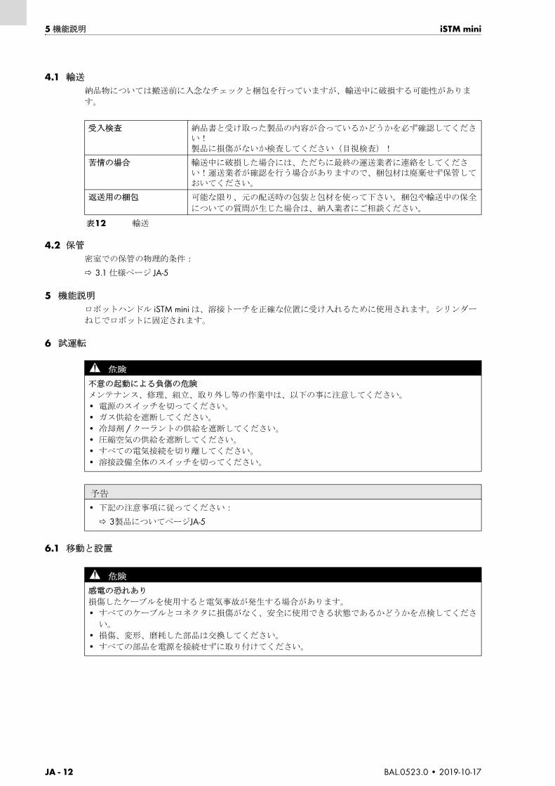
JA - 12 BAL.0523.0 • 2019-10-17
5 機能説明 iSTM mini
4.1 輸送
納品物については搬送前に入念なチェックと梱包を行っていますが、輸送中に破損する可能性がありま
す。
4.2 保管
密室での保管の物理的条件:
3.1 仕様ページ JA-5
5 機能説明
ロボットハンドル iSTM mini は、溶接トーチを正確な位置に受け入れるために使用されます。シリンダー
ねじでロボットに固定されます。
6 試運転
6.1 移動と設置
受入検査 納品書と受け取った製品の内容が合っているかどうかを必ず確認してください!製品に損傷がないか検査してください(目視検査)!
苦情の場合 輸送中に破損した場合には、ただちに 終の運送業者に連絡をしてください!運送業者が確認を行う場合がありますので、梱包材は廃棄せず保管しておいてください。
返送用の梱包 可能な限り、元の配送時の包装と包材を使って下さい。梱包や輸送中の保全
についての質問が生じた場合は、納入業者にご相談ください。
表12 輸送
危険
不意の起動による負傷の危険
メンテナンス、修理、組立、取り外し等の作業中は、以下の事に注意してください。
• 電源のスイッチを切ってください。
• ガス供給を遮断してください。
• 冷却剤 / クーラントの供給を遮断してください。
• 圧縮空気の供給を遮断してください。
• すべての電気接続を切り離してください。
• 溶接設備全体のスイッチを切ってください。
予告
• 下記の注意事項に従ってください:
3製品についてページJA-5
危険
感電の恐れあり
損傷したケーブルを使用すると電気事故が発生する場合があります。
• すべてのケーブルとコネクタに損傷がなく、安全に使用できる状態であるかどうかを点検してくださ
い。
• 損傷、変形、磨耗した部品は交換してください。
• すべての部品を電源を接続せずに取り付けてください。
iSTM mini 6 試運転
BAL.0523.0 • 2019-10-17 JA - 13
注意
怪我の危険
機器や付属品の落下により負傷する恐れがあります。
• 開封の際は適切な場所を選択してください。
• 急に持ち上げたり降ろしたりしないようにしてください。
• コンポーネントを持ち上げて人や他の機器の上を通らないようにしてください。
• コンポーネントを直立位置にしたまま運んでください。
• 装置は適切なサポートを用いて取り付けてください。
• ロボットは適切な取付位置に置いてください。
6.2 ロボットのメンテナンス位置ページ JA-14
• 安全な状態であるよう注意してください。
• 次の作業者用保護具を着用してください:安全靴、作業手袋、ヘルメット、耳栓。
• 作業に関係しない人に危険の及ぶ場所から離れるよう指示してください。
• 個々のコンポーネントの重量に注意してください。
3.1 仕様ページ JA-5
注意
溶接ワイヤによる貫通や刺し傷の危険があります
空気配管の接続時に目を負傷する危険があります。
ワイヤーブレーキ付属バージョンでは、密閉または正しく接続された配管で圧縮空気が噴出して粒子が
目に入るおそれがあります。
これを防ぐために、以下の接続手順を守ってください。
• 圧縮空気ホースをワイヤーブレーキに接続します。
• 圧縮空気供給を接続します。
• 作業者用保護具を着用してください。
注意
転倒の恐れあり
不適切な組立により負傷またはコンポーネントの損傷が発生する恐れがあります。
• 電源線を取り外します。
• コンポーネントを適切な設置場所(水平で固く乾燥した面)に置いてください。
• 10° の 大傾斜角に注意してください。
予告
• 制御装置類とポートは自由にアクセスできるようにしておいてください。
• 雨や直射日光が当たらないように各構成部を保護してください。
• 本装置は、乾燥していて清潔で換気された場所でのみ使用するようにしてください。
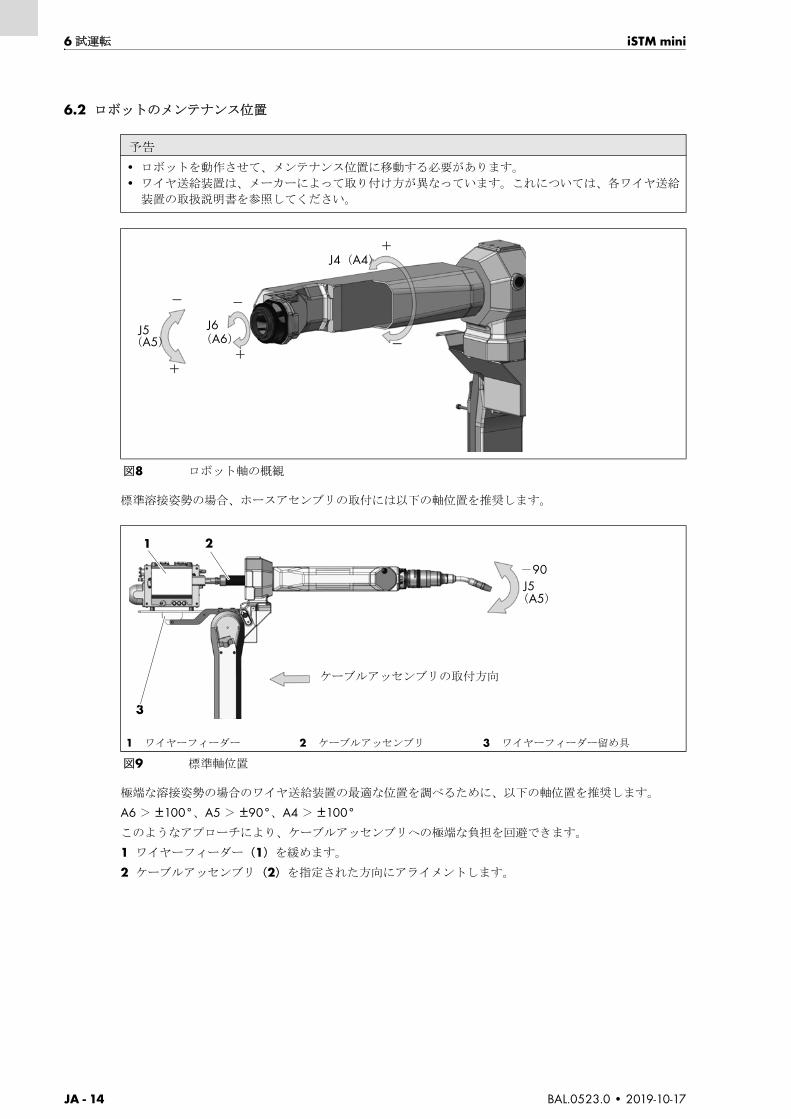
JA - 14 BAL.0523.0 • 2019-10-17
6 試運転 iSTM mini
6.2 ロボットのメンテナンス位置
標準溶接姿勢の場合、ホースアセンブリの取付には以下の軸位置を推奨します。
極端な溶接姿勢の場合のワイヤ送給装置の 適な位置を調べるために、以下の軸位置を推奨します。
A6 > ±100°、A5 > ±90°、A4 > ±100°
このようなアプローチにより、ケーブルアッセンブリへの極端な負担を回避できます。
1 ワイヤーフィーダー(1)を緩めます。
2 ケーブルアッセンブリ(2)を指定された方向にアライメントします。
予告
• ロボットを動作させて、メンテナンス位置に移動する必要があります。
• ワイヤ送給装置は、メーカーによって取り付け方が異なっています。これについては、各ワイヤ送給
装置の取扱説明書を参照してください。
図8 ロボット軸の概観
1 ワイヤーフィーダー 2 ケーブルアッセンブリ 3 ワイヤーフィーダー留め具
図9 標準軸位置
J4(A4)
J6(A6)
J5(A5)
+
+
+
-
-
-
ケーブルアッセンブリの取付方向
1
3
2
J5(A5)
-90

iSTM mini 6 試運転
BAL.0523.0 • 2019-10-17 JA - 15
6.2.1 iSTM mini のロボットへの固定
iSTM mini(1)を、8 本のシリンダーねじ(M4x12)(2)を使って 大締め付けトルク M = 4 Nm で溶
接ロボット(5)に取り付けます。
溶接ロボット(5)の基準ピン穴(4)が、iSTM mini(1)と溶接ロボット(5)の間の基準位置となりま
す。
6.2.2 ケーブルアッセンブリをロボットに取付
1 iSTM mini2 シリンダーねじ M4x12(8 個)
3 間隔アダプタ iSTM mini4 基準ピン穴
5 溶接ロボット
図10 iSTM miniのロボットへの固定
予告
• iSTM mini(1)の間隔アダブタ(3)のバージョンは使用する溶接ロボ
ット(5)に依存します。シリンダーねじ(2)の本数およびサイズも同
様です。
1 2 3 54
予告
• 取付後、密でない箇所がないか、点検してください。
• すべての回線(シールドガス、圧縮空気管および冷却剤ホース)は、ねじれのないよう、十分な遊び
を持って取り付けてください。
警告
怪我の危険
回転部品により重傷を負う恐れがあります。
• メンテナンスで圧縮空気を使用して清掃する場合、適切な防護服や安全眼鏡(ゴーグル)を着用して
ください。

JA - 16 BAL.0523.0 • 2019-10-17
6 試運転 iSTM mini
iSTM mini、ABIROB® G 用
1 ケーブルアッセンブリは(8)、組み立てられた iSTM mini(7)溶接トーチインターフェースを通して
操作されます。ケーブルアッセンブリ(8)を組み立て方向に組み立てます。
2 すでに取り付けられている場合、ストレートねじ留め(10)を取り外します。
3 ケーブルアッセンブリ(8)を 7 個のシリンダーねじ(M4 × 16)(2)で iSTM mini(7)に取り付けま
す。 大締め付けトルク M = 4 Nm。
4 リアカバー(6)を iSTM mini に 2 本のシリンダーねじ M3×6(3)で取り付けます。
5 前カバー(4)を、2 皿ねじ DIN 965 M3×5(5)でケーブルアッセンブリに取り付けます。
6 カバーを iSTM mini(7)に取り付けます。
7 ネジ継ぎ手 Ø6 をネジ留めサポート二面幅 11 とともにしっかりと取り付けます。
8 シールドガス用ホースを差し込み、シールドガス供給に接続します。
1 カバー
2 シリンダーねじ M4x16(7 個)
3 シリンダーねじ M3x6(2 個)
4 前カバー
5 皿ねじ M3×5(2 個)
6 リアカバー
7 iSTM mini8 ケーブルアッセンブリ
9 機械側の接続
10 ネジ継ぎ手 Ø6/G1/8"11 ネジ留めサポート二面幅 1112 絶縁ホース Ø6
図11 ケーブルアッセンブリをiSTM mini、ABIROB® G用に取り付けます。
予告
• 溶接電流接続はワイヤーフィーダーに接続されておく必要があります。
ワイヤーフィーダーの取扱説明書。
取り付け方向
1 2 3 4 5 6 7 8 9
10
1112
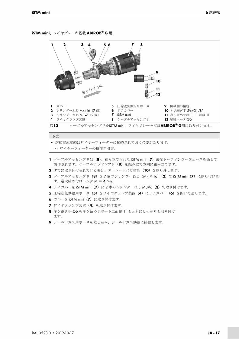
iSTM mini 6 試運転
BAL.0523.0 • 2019-10-17 JA - 17
iSTM mini、ワイヤブレーキ搭載 ABIROB® G 用
1 ケーブルアッセンブリは(8)、組み立てられた iSTM mini(7)溶接トーチインターフェースを通して
操作されます。ケーブルアッセンブリ(8)を組み立て方向に組み立てます。
2 すでに取り付けられている場合、ストレートねじ留め(10)を取り外します。
3 ケーブルアッセンブリ(8)を 7 個のシリンダーねじ(M4 × 16)(2)で iSTM mini(7)に取り付けま
す。 大締め付けトルク M = 4 Nm。
4 リアカバーを iSTM mini(7)に 2 本のシリンダーねじ M3×6(3)で取り付けます。
5 圧縮空気供給用ホース(5)をワイヤクランプ装置(4)にリアカバー(6)を開いて通します。
6 カバーを iSTM mini(7)に取り付けます。
7 ワイヤクランプ装置(4)を取り付けます。
8 ネジ継ぎ手 Ø6 をネジ留めサポート二面幅 11 とともにしっかりと取り付け
ます。
9 シールドガス用ホースを差し込み、シールドガス供給に接続します。
1 カバー
2 シリンダーねじ M4x16(7 個)
3 シリンダーねじ M3x6(2 個)
4 ワイヤクランプ装置
5 圧縮空気供給用ホース
6 リアカバー
7 iSTM mini8 ケーブルアッセンブリ
9 機械側の接続
10 ネジ継ぎ手 Ø6/G1/8"11 ネジ留めサポート二面幅 1112 絶縁ホース Ø6
図12 ケーブルアッセンブリをiSTM mini、ワイヤブレーキ搭載ABIROB® G用に取り付けます。
予告
• 溶接電流接続はワイヤーフィーダーに接続されておく必要があります。
ワイヤーフィーダーの操作手引書。
取り付け方向
1 2 3 4 5 6 7 8
10
1112
9

JA - 18 BAL.0523.0 • 2019-10-17
6 試運転 iSTM mini
iSTM mini、ABIROB® W 用
1 ケーブルアッセンブリは(4)、取り付けた iSTM mini(5)溶接トーチカップリングを通して操作され
ます。ケーブルアッセンブリ(4)を組み立て方向に組み立てます。
2 ケーブルアッセンブリ(4)を 7 個のシリンダーねじ(M4 × 16)(3)で iSTM mini(5)に取り付けま
す。 大締め付けトルク M = 4 Nm。
3 カバー(2)と保護キャップ(1)を iSTM mini(5)に取り付けます。
4 絶縁ホース(7)を差し込み、シールドガス供給に接続します。
5 冷却剤ライン(6)を接続します。
1 保護キャップ
2 カバー
3 シリンダーねじ M4x16(7 個)
4 ケーブルアッセンブリ
5 iSTM mini6 冷却剤ライン(赤+青)
7 絶縁ホース Ø6
図13 ケーブルアッセンブリをiSTM mini、ABIROB® W用に取り付けます。
取り付け方向
1 2 3 4 5
6
7
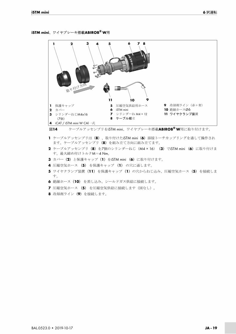
iSTM mini 6 試運転
BAL.0523.0 • 2019-10-17 JA - 19
iSTM mini、ワイヤブレーキ搭載ABIROB® W用
1 ケーブルアッセンブリは(8)、取り付けたiSTM mini(6)溶接トーチカップリングを通して操作され
ます。ケーブルアッセンブリ(8)を組み立て方向に組み立てます。
2 ケーブルアッセンブリ(8)を7個のシリンダーねじ(M4 × 16)(3)でiSTM mini (6)に取り付けま
す。 大締め付けトルクM=4 Nm。
3 カバー(2)と保護キャップ(1)をiSTM mini (6)に取り付けます。
4 圧縮空気ホース (5) を保護キャップ (1) の穴に通します。
5 ワイヤクランプ装置 (11) を保護キャップ (1)の穴からねじ込み、圧縮空気ホース (5) を接続しま
す。
6 絶縁ホース(10) を差し込み、シールドガス供給に接続します。
7 圧縮空気ホース (5) を圧縮空気供給に接続します(図なし)。
8 冷却剤ライン(9)を接続します。
1 保護キャップ
2 カバー
3 シリンダーねじM4x16(7個)
4 iCAT / iSTM mini W CAl一式
5 圧縮空気供給用ホース6 iSTM mini7 シリンダーね M4 × 128 ケーブル組立
9 冷却剤ライン(赤+青)
10 絶縁ホースØ611 ワイヤクランプ装置
図14 ケーブルアッセンブリをiSTM mini、ワイヤブレーキ搭載ABIROB® W用に取り付けます。
1 2 3 4 5 6 7 8
91011
取り付け方向

JA - 20 BAL.0523.0 • 2019-10-17
6 試運転 iSTM mini
冷却剤 / クーラントの接続
試運転時またはケーブルアッセンブリ交換ごとに、必ず冷却システムのエア抜きを行ってください。以下
の手順を実施してください。
1 冷却剤復水ホースを循環冷却装置から、また冷却剤接続を電源から外し、収集容器を通じて空にしま
す。
2 冷却剤復水ホースの開口部を閉じ、すぐにまた開けて開放します。これを冷却剤が一貫して気泡なく
収集容器に流れ出るまで繰り返します。
3 循環冷却装置をオフにし、冷却剤復水ホースを再び接続します。
6.3 トーチネック、ABIROB® G の固定
1 ABIROB® G トーチネック(1)にノズルスティック、電流ノズル、ガスノズルを装着します。
梱包冊子 ABIROB®350 GC
2 シリンダーねじ(4)を緩めます。
3 ABIROB® G トーチネックを溶接トーチインターフェースに取り付けます。トーチは完全に溶接トー
チインターフェイスに差し込む必要があります。
4 トーチを固定するには、シリンダーねじ(4)を 大締め付けトルク
M = 6 Nm でしっかりと閉めます。
警告
火傷の危険
トーチは冷却剤を使用しない、または冷却剤流量が少なすぎる溶接により過熱します。
• 適切な保護手袋を着用してください。
• 冷却剤 / クーラントのレベルを定期的に点検してください。
予告
• 冷却剤の供給側および復水側が決められたとおりに取り付けられているよう注意してください。送水
口=青、復水口=赤
• イオン交換や脱塩された水を冷却剤 / クーラントまたは漏れ・流量テストに使用しないでください。
お使いの溶接トーチの寿命に影響することがあります。
• 液冷式の溶接トーチでは BTC シリーズの ABICOR BINZEL 冷却剤 / クーラントの使用を推奨します。
これに関して該当する安全データーシートを遵守してください。
1 トーチネック
2 保護キャップ
3 iSTM mini4 シリンダーねじ M5×10
図15 トーチネックABIROB® Gの固定
1 2 3
4
取り付け方向

iSTM mini 6 試運転
BAL.0523.0 • 2019-10-17 JA - 21
5 保護キャップ(2)をかぶせます。
6.4 トーチネック ABIROB® W の固定
1 ABIROB® W トーチネック(1)にノズルスティック、電流ノズル、ガスノズルを装着します。
2 止めピン(3)をマークが付いている孔に差し込みます。
トーチネック ABIROB® W(1)はこの位置にのみ固定することができます。
3 ABIROB® W トーチネックを止めナット(2)で iSTM mini(4)のインターフェースに取り付けます。
予告
• シリンダーねじ(4)を、取付済み溶接トーチを使用して取り付けます。
1 トーチネック
2 止めナット
3 止めピン
4 iSTM mini
図16 トーチネックABIROB® Wの固定
予告
• 溶接トーチを数日間使用した後、ナットを手でゆるめることができなくなる場合があります。ゆるめ
るにはそれに適したスパナを使用してください。
• 溶接トーチをゆるめるのにペンチは使用しないでください。
1 2 3
4取り付け方向

JA - 22 BAL.0523.0 • 2019-10-17
6 試運転 iSTM mini
6.5 ワイヤーガイドの取付
6.5.1 基準仕様品
1 ケーブルアッセンブリに、トーチネックと消耗品とともに装置を施します。
2 ワイヤーガイドを、ケーブルアッセンブリの中にぶつかるまで差し込みます。
3 a が突き出し(2)ているか確認します。
4 前方からのワイヤーガイドを a の寸法(2)に巻いて短くします。取り付けの後にワイヤーガイドがス
パナ ― の下に簡単に収まるようにワイヤーガイドを短くします。
5 ワイヤーガイドを、ケーブルアッセンブリの中にぶつかるまで差し込み、位置決めネジ(M4x5)(3)で固定します。
以下を確認してください:
9.2 ワイヤーガイドの清掃ページ JA-27
6.5.2 ワイヤブレーキ仕様品
ワイヤーブレーキの付いたタイプのトーチネックは特別なネックライナーを装備する必要があります。
予告
• 新しい未使用のワイヤガイドは、実際のケーブルアッセンブリの長さに短縮する必要があります。
• ワイヤガイド(ライナーまたは PA ライナー)の交換の際は、使用説明書の製品情報にご注意くださ
い。
• トーチ側を 15 mm 短くしたのち、ワイヤーガイドの絶縁材を取り除きます。
1 スリーブ
2 a の突き出し
3 位置決めネジ ISO 4027–M4×54 O リング
図17 ワイヤーガイドが突き出していないか確認します
予告
• 本章のワイヤーガイドの取り付けに位置決めネジ(3)があること。その他の機械接続の場合はこれ
は含まれません。
1 2a 3
4
予告
• 新しい未使用のワイヤガイドは、実際のケーブルアッセンブリの長さに短縮する必要があります。
• ワイヤガイド(ライナーまたは PA ライナー)の交換の際は、使用説明書の製品情報にご注意くださ
い。
• トーチ側を 15 mm 短くしたのち、ワイヤーガイドの絶縁材を取り除きます。

iSTM mini 7 運転
BAL.0523.0 • 2019-10-17 JA - 23
6.5.3 ワイヤーガイドの短縮
図 17 ワイヤーガイドが突き出していないか確認しますページ JA-22
1 ケーブルアッセンブリに、トーチネックと消耗品とともに装置を施します。
2 ワイヤーガイドを、ケーブルアッセンブリの中にぶつかるまで差し込みます。
3 a が突き出し(2)ているか確認します。
4 前方からのワイヤーガイドを a の寸法(2)に巻いて短くします。取り付けの後にワイヤーガイドがス
パナ ― の下に簡単に収まるようにワイヤーガイドを短くします。
5 ワイヤーガイドを、ケーブルアッセンブリの中にぶつかるまで差し込み、位置決めネジ(M4x5)(3)で固定します。
7 運転
iSTM mini は溶接トーチの溶接プロセスに組み込まれているため、各トーチと使用溶接電源の起動後、操
作ステップが実行されます。これについては、ご使用になる溶接トーチの取扱説明書に従ってください。
図18 ワイヤーガイドの短縮
予告
• 絶縁体の付いたワイヤーガイドが Ø5 mm を超える場合、ワイヤーガイドをトーチ側で 15 mm 短くし
てからはがす必要があります。
• 絶縁体のないワイヤーガイドの直径は、Ø5 mm を超えてはなりません。
15 mm
≤5
mm
≥5
mm
警告
電気ショック。火傷。
溶けた箇所の燃焼。
• 溶接トーチと接触すると感電するおそれがあります。アークによって目がチカチカしたり、火傷をす
るおそれがあります。
• BGV D1 に準拠した適切な保護装備を使用し、接触する可能性のある通電部品や溶接設備設置時の電
気分離を回避してください。
注意
足滑り、つまづき、転倒。
ロボットセルに侵入する際にワイヤー残や潤滑剤で足が滑ることがあります。
• これを防ぐには、適切な保護具を使用します。
• 作業者用保護具を着用してください。
予告
• 溶接技術コンポーネントの記述に従ってください。

JA - 24 BAL.0523.0 • 2019-10-17
8 運転終了 iSTM mini
8 運転終了
廃止準備作業は、各溶接トーチによって異なります。
これについては、ご使用になる溶接トーチ、あるいは溶接電源の取扱説明書に従ってください。
9 整備と清掃
長寿命と完全な機能を確保するには、定期的な整備と清掃の継続が必須です。
予告
• 運転終了時は、溶接システムのコンポーネントの停止手順書に従ってください。
危険
不意の起動による負傷の危険
メンテナンス、修理、組立、取り外し等の作業中は、以下の事に注意してください。
• 電源のスイッチを切ってください。
• 圧縮空気の供給を遮断してください。
• 冷却剤 / クーラントの供給を遮断してください。
• 圧縮空気の供給を遮断してください。
• すべての電気接続を切り離してください。
• 溶接設備全体のスイッチを切ってください。
危険
感電の恐れあり
損傷したケーブルを使用すると電気事故が発生する場合があります。
• すべてのケーブルとコネクタに損傷がなく、安全に使用できる状態であるかどうかを点検してくださ
い。
• 損傷、変形、磨耗した部品は交換してください。
警告
怪我の危険
回転部品により重傷を負う恐れがあります。
• メンテナンスで圧縮空気を使用して清掃する場合、適切な防護服や安全眼鏡(ゴーグル)を着用して
ください。
予告
• 整備作業中および清掃作業中は、ご自身が使用している保護具を必ず着用してください。
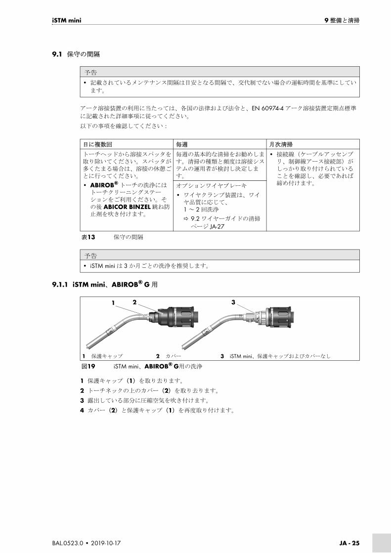
iSTM mini 9 整備と清掃
BAL.0523.0 • 2019-10-17 JA - 25
9.1 保守の間隔
アーク溶接装置の利用に当たっては、各国の法律および法令と、EN 60974-4 アーク溶接装置定期点標準
に記載された詳細事項に従ってください。
以下の事項を確認してください:
9.1.1 iSTM mini、ABIROB® G 用
1 保護キャップ(1)を取り去ります。
2 トーチネックの上のカバー(2)を取り去ります。
3 露出している部分に圧縮空気を吹き付けます。
4 カバー(2)と保護キャップ(1)を再度取り付けます。
予告
• 記載されているメンテナンス間隔は目安となる間隔で、交代制でない場合の運転時間を基準にしてい
ます。
日に複数回 毎週 月次清掃
トーチヘッドから溶接スパッタを取り除いてください。スパッタが多くたまる場合は、溶接の休憩ごとに行ってください。
• ABIROB® トーチの洗浄にはトーチクリーニングステーションをご利用ください。その後 ABICOR BINZEL 跳ね防止剤を吹き付けます。
毎週の基本的な清掃をお勧めします。清掃の種類と頻度は溶接システムの運用者が検討し決定します。
• 接続線(ケーブルアッセンブリ、制御線アース接続部)がしっかり取り付けられていることを確認し、必要であれば締め付けます。オプションワイヤブレーキ
• ワイヤクランプ装置は、ワイヤ品質に応じて、1 ~ 2 回洗浄
9.2 ワイヤーガイドの清掃
ページ JA-27
表13 保守の間隔
予告
• iSTM mini は 3 か月ごとの洗浄を推奨します。
1 保護キャップ 2 カバー 3 iSTM mini、保護キャップおよびカバーなし
図19 iSTM mini、ABIROB® G用の洗浄
1 2 3

JA - 26 BAL.0523.0 • 2019-10-17
9 整備と清掃 iSTM mini
9.1.2 iSTM mini、ワイヤブレーキ搭載 ABIROB® G 用
1 圧縮空気ホース(5)を緩めます。
2 ワイヤクランプ装置(4)を取り外します。
3 保護キャップ(1)を取り去ります。
4 トーチネックの上のカバー(2)を取り去ります。
5 露出している部分に圧縮空気を吹き付けます。
6 カバー(2)、保護キャップ(1)、ワイヤクランプ装置(4)に圧縮空気ホース(5)を再度取り付けま
す。
9.1.3 iSTM mini、ABIROB® W用
1 トーチネック ABIROB® W(1)を取り外します。
2 保護キャップ(2)をカバー(3)と一緒に取り外します。
3 iSTM mini にあるトーチ、カバー、保護キャップ(4)のない露出した部品に圧縮空気を吹きつけます。
4 カバー(3)と保護キャップ(2)を取り付けます。
5 トーチネック ABIROB® W(1)を再び取り付けます。
1 保護キャップ
2 カバー
3 保護キャップおよびカバーのないiSTM mini
4 ワイヤクランプ装置
5 圧縮空気ホース
図20 iSTM mini、ワイヤブレーキ搭載ABIROB® G用の洗浄
1 2 3 4 5
1 トーチネック
2 保護キャップ
3 カバー
4 iSTM mini、トーチネック、カバー、保護キャップなし
図21 iSTM mini、ABIROB® W用の洗浄
1 2 3 4

iSTM mini 10 故障と対策
BAL.0523.0 • 2019-10-17 JA - 27
9.1.4 iSTM mini、ワイヤブレーキ搭載ABIROB® W用
1 圧縮空気ホース (4) を緩めます。
2 ワイヤクランプ装置 (5) を取り外します。
3 トーチネックABIROB® W(1)を取り外します。
4 保護キャップ (2) に取り外します。
5 をカバー (3) に取り外します。
6 露出している部分に圧縮空気を吹き付けます。
7 カバー (3) 、保護キャップ (2) 、ワイヤクランプ装置 (5) に圧縮空気ホース (4) を再度取り付けま
す。
8 トーチネックABIROB® W(1)を再び取り付けます。
9.2 ワイヤーガイドの清掃
図 17 ワイヤーガイドが突き出していないか確認しますページ JA-22
整備および清掃の間の期間に O- リング(4)に破損がないか点検し、場合によっては交換してください。
10故障と対策
添付文書の保証の手引きに従ってください。疑問や問題がある場合は、担当の専門ディーラーまたは製造
業者にお問い合わせください。
1 トーチネック
2 保護キャップ
3 カバー
4 圧縮空気ホース
5 ワイヤクランプ装置
図22 iSTM mini、ABIROB® W用の洗浄
1 2 3 4
5
危険
怪我の危険と資格のない者の作業遂行による機器の損傷
不適切な修理や製品への変更は、重度の負傷または機器への損傷を引き起こす場合があります。資格の
ない者による変更が行われた場合、保証は無効となります。
• 機器及びシステムでのいかなる作業も資格のある人員に限定されます。
危険
火傷の危険
漏れ出た高温の冷却剤 / クーラントおよび高温の表面による火傷の危険。
• 保守、補修、取り付け、分解および修理作業前に冷却ユニットをオフにしてください。
• 保護手袋を着用してください。
予告
• 溶接技術コンポーネントの記述に従ってください。

JA - 28 BAL.0523.0 • 2019-10-17
11 分解 iSTM mini
11 分解
故障 原因 解決
ケーブルアッセンブリは
iSTM mini に差し込みでき
ません
• 差込口接続とガスホースをまだ取り付けます
• 差し込み口接続とガスホースを解体します
• ケーブルアッセンブリフランジが iSTM mini に正しく取り付けられていません
• 正しい位置に注意します
ガス損失 • ライナーニップルの O- リングパッキンの損傷
• O- リングパッキンを交換します
• トーチネックの O- リングパッキンの損傷
• O- リングパッキンを交換します
• 機械側のシールドガス接続のもれ
• 場合により絶縁ホースを交換します
溶接ケーブルが正しく
通っていない
• ワイヤーコンジットが汚れています
• ワイヤーコンジットを分解し、圧縮空気でエアブローをかけます。
• 保護ゴーグル着用します
• 9 整備と清掃ページ JA-24
• ワイヤーコンジットが摩耗しています
• ワイヤーコンジットを取り替えます
• ワイヤーコンジットが短く切断されすぎています
• 新しいワイヤーコンジットを取り付けます
ワイヤーブレーキ仕様品
の場合にワイヤークリッ
プが機能しなくなる
• 汚染の堆積が多すぎる • 圧縮空気を使ったワイヤーブレーキコンポーネントの清掃
• 保護ゴーグル着用します
• 圧縮空気供給が故障しています • 圧縮空気供給を接続し、曲がった箇所がないようにします
• ワイヤクランプ装置のピストンが故障しています
• ワイヤクランプ装置を交換します
表14 故障と対策
危険
不意の起動による負傷の危険
メンテナンス、修理、組立、取り外し等の作業中は、以下の事に注意してください。
• 電源のスイッチを切ってください。
• 圧縮空気の供給を遮断してください。
• 冷却剤 / クーラントの供給を遮断してください。
• すべての電気接続を切り離してください。
• 溶接設備全体のスイッチを切ってください。
危険
火傷の危険
漏れ出た高温の冷却剤 / クーラントおよび高温の表面による火傷の危険。
• 保守、補修、取り付け、分解および修理作業前に冷却ユニットをオフにしてください。
• 保護手袋を着用してください。
予告
• 溶接技術コンポーネントの記述に従ってください。
• 下記の章の情報をご確認ください:
8運転終了ページJA-24。
iSTM mini 12 廃棄
BAL.0523.0 • 2019-10-17 JA - 29
1 ワイヤーフィーダーからケーブルアッセンブリを外します。
2 ケーブルアッセンブリを抜き取ります。
3 トーチネックを緩め、取り外します。
6.3 トーチネック、ABIROB® G の固定ページ JA-20
6.4 トーチネック ABIROB® W の固定ページ JA-21
6.5 ワイヤーガイドの取付ページ JA-22
4 ロボットから iSTM mini を取り外します。
6.2 ロボットのメンテナンス位置ページ JA-14
12廃棄
廃棄の際には、現地の規定、法律、規格、基準などを必ず守ってください。製品を規定通りに廃棄するた
めには、事前に分解が必要となります。
11 分解ページ JA-28
12.1材料
本製品は、大部分がプラスチック、鉄、非鉄金属でできています。鉄と非鉄金属は、製鋼所や製錬所で再
び溶かすことができるため、ほとんど無制限に再利用できます。材料をリサイクルするための分別に備え
て、使用しているプラスチックについても詳細を表示しています。
12.2補助材料
土壌や水を汚染しないために、油、グリース、および清掃剤を地面や排水口に流さないようにしてくださ
い。これらの液体は適切な容器に保管し、適切な施設で処分してください。その際、国や地方の関連規定
や、材料メーカーにより指定されている製品安全性データーシートの廃棄処理に関する予告を守ってくだ
さい。汚染された掃除道具(ハケや布など)は、必ずメーカーの指示に従って処分してください。
12.3梱包
ABICOR BINZEL では、運送時の梱包をできるだけ減らしています。梱包材は再利用を考慮して選定され
ています。
危険
感電の恐れあり
損傷したケーブルを使用すると電気事故が発生する場合があります。
• すべてのケーブルとコネクタに損傷がなく、安全に使用できる状態であるかどうかを点検してくださ
い。
• 損傷、変形、磨耗した部品は交換してください。

T E C H N O L O G Y F O R T H E W E L D E R ´ S W O R L D .
BAL.0
523.
0 •
201
9-10
-17
w w w . b i n z e l - a b i c o r . c o m
Alexander Binzel Schweisstechnik GmbH & Co. KGKiesacker · 35418 Buseck · GERMANY T +49 64 08 / 59-0F +49 64 08 / [email protected]