Istruzioni per l’uso e l’installazione...
60
Instructions for use and installation Cooker Hood Istruzioni per l’uso e l’installazione Cappa Mode d’emploi et installation Hotte de Cuisine Bedienungsanleitung und Einrichtung Dunstabzugshaube Kullanım ve montaj talimatları Davlumbaz FAK 907 I IT FR DE TR GB
Transcript of Istruzioni per l’uso e l’installazione...
Instructions for use and installation Cooker Hood
Istruzioni per l’uso e l’installazione Cappa
Mode d’emploi et installation Hotte de Cuisine
Bedienungsanleitung und Einrichtung Dunstabzugshaube
Kullanım ve montaj talimatları Davlumbaz
FAK 907 I
IT
FR
DE
TR
GB
EN
2 2
Instructions Manual INDEX RECOMMENDATIONS AND SUGGESTIONS......................................................................................................................7 CHARACTERISTICS..............................................................................................................................................................8 INSTALLATION ....................................................................................................................................................................10 USE.......................................................................................................................................................................................14 MAINTENANCE....................................................................................................................................................................15

IT
3 3
Libretto di Istruzioni INDICE CONSIGLI E SUGGERIMENTI ............................................................................................................................................17 CARATTERISTICHE ............................................................................................................................................................18 INSTALLAZIONE..................................................................................................................................................................20 USO ......................................................................................................................................................................................24 MANUTENZIONE .................................................................................................................................................................25

FR
4 4
Manuel d’Instructions SOMMAIRE CONSEILS ET SUGGESTIONS ..........................................................................................................................................27 CARACTERISTIQUES .........................................................................................................................................................28 INSTALLATION ....................................................................................................................................................................30 UTILISATION........................................................................................................................................................................34 ENTRETIEN..........................................................................................................................................................................35
DE
5 5
Bedienungsanleitung INHALTSVERZEICHNIS EMPFEHLUNGEN UND HINWEISE....................................................................................................................................37 CHARAKTERISTIKEN..........................................................................................................................................................38 MONTAGE............................................................................................................................................................................40 BEDIENUNG.........................................................................................................................................................................44 WARTUNG............................................................................................................................................................................45
TR
6 6
Kullanim Kilavuku IÇERIKLER TAVSIYELER VE ÖNERILER ..............................................................................................................................................47 ÖZELLIKLER ........................................................................................................................................................................48 MONTAJ ...............................................................................................................................................................................50 KULLANIM ............................................................................................................................................................................54 BAKIM...................................................................................................................................................................................55
EN
7 7
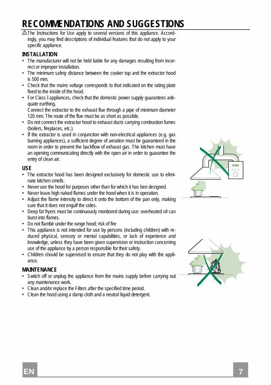
RECOMMENDATIONS AND SUGGESTIONS The Instructions for Use apply to several versions of this appliance. Accord-
ingly, you may find descriptions of individual features that do not apply to your specific appliance.
INSTALLATION • The manufacturer will not be held liable for any damages resulting from incor-
rect or improper installation. • The minimum safety distance between the cooker top and the extractor hood
is 500 mm. • Check that the mains voltage corresponds to that indicated on the rating plate
fixed to the inside of the hood. • For Class I appliances, check that the domestic power supply guarantees ade-
quate earthing. Connect the extractor to the exhaust flue through a pipe of minimum diameter
120 mm. The route of the flue must be as short as possible. • Do not connect the extractor hood to exhaust ducts carrying combustion fumes
(boilers, fireplaces, etc.). • If the extractor is used in conjunction with non-electrical appliances (e.g. gas
burning appliances), a sufficient degree of aeration must be guaranteed in the room in order to prevent the backflow of exhaust gas. The kitchen must have an opening communicating directly with the open air in order to guarantee the entry of clean air.
USE • The extractor hood has been designed exclusively for domestic use to elimi-
nate kitchen smells. • Never use the hood for purposes other than for which it has ben designed. • Never leave high naked flames under the hood when it is in operation. • Adjust the flame intensity to direct it onto the bottom of the pan only, making
sure that it does not engulf the sides. • Deep fat fryers must be continuously monitored during use: overheated oil can
burst into flames. • Do not flambè under the range hood; risk of fire • This appliance is not intended for use by persons (including children) with re-
duced physical, sensory or mental capabilities, or lack of experience and knowledge, unless they have been given supervision or instruction concerning use of the appliance by a person responsible for their safety.
• Children should be supervised to ensure that they do not play with the appli-ance.
MAINTENANCE • Switch off or unplug the appliance from the mains supply before carrying out
any maintenance work. • Clean and/or replace the Filters after the specified time period. • Clean the hood using a damp cloth and a neutral liquid detergent.
EN
8 8
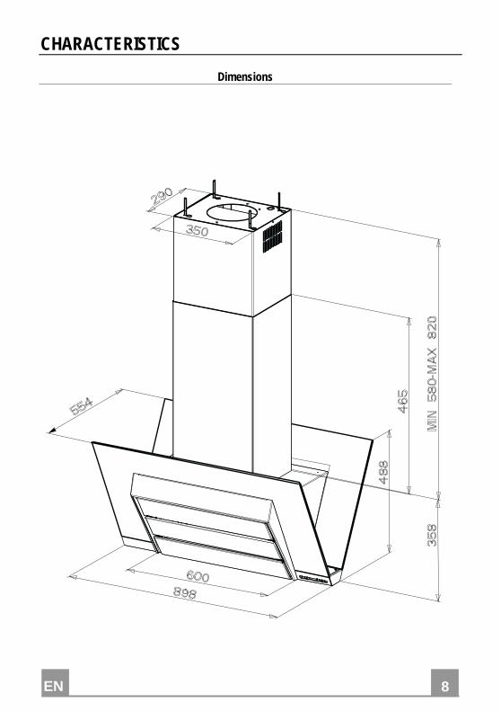
CHARACTERISTICS
Dimensions
EN
9 9
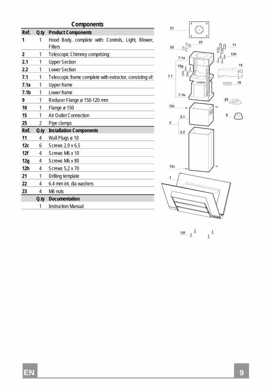
Components Ref. Q.ty Product Components 1 1 Hood Body, complete with: Controls, Light, Blower,
Filters
2 1 Telescopic Chimney comprising:
2.1 1 Upper Section
2.2 1 Lower Section
7.1 1 Telescopic frame complete with extractor, consisting of:
7.1a 1 Upper frame
7.1b 1 Lower frame
9 1 Reducer Flange ø 150-120 mm
10 1 Flange ø 150
15 1 Air Outlet Connection
25 2 Pipe clamps Ref. Q.ty Installation Components 11 4 Wall Plugs ø 10
12c 6 Screws 2,9 x 6,5
12f 4 Screws M6 x 10
12g 4 Screws M6 x 80
12h 4 Screws 5,2 x 70
21 1 Drilling template
22 4 6.4 mm int. dia washers
23 4 M6 nuts Q.ty Documentation 1 Instruction Manual
����
���
����
���
����
�
���
���
��
��
��
��
�
���
��
��
��
�
�
EN
10
10
INSTALLATION
Drilling the Ceiling/shelf and fixing the frame
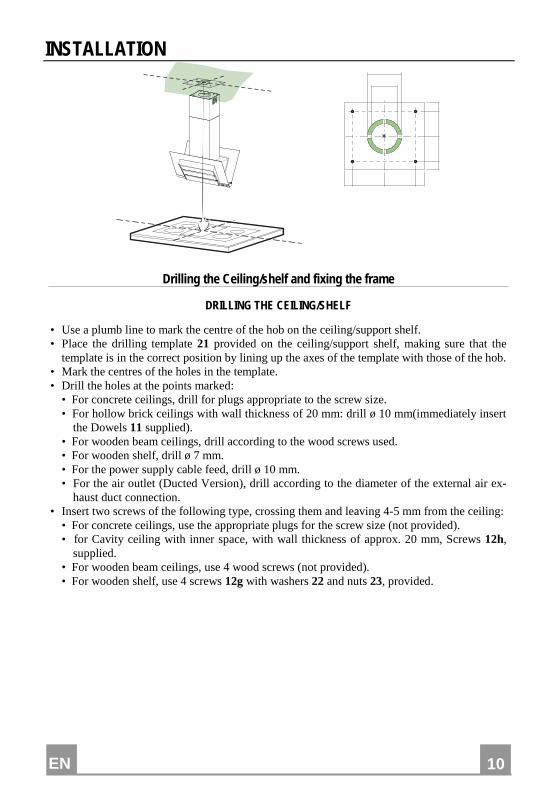
DRILLING THE CEILING/SHELF
• Use a plumb line to mark the centre of the hob on the ceiling/support shelf. • Place the drilling template 21 provided on the ceiling/support shelf, making sure that the
template is in the correct position by lining up the axes of the template with those of the hob. • Mark the centres of the holes in the template. • Drill the holes at the points marked:
• For concrete ceilings, drill for plugs appropriate to the screw size. • For hollow brick ceilings with wall thickness of 20 mm: drill ø 10 mm(immediately insert
the Dowels 11 supplied). • For wooden beam ceilings, drill according to the wood screws used. • For wooden shelf, drill ø 7 mm. • For the power supply cable feed, drill ø 10 mm. • For the air outlet (Ducted Version), drill according to the diameter of the external air ex-
haust duct connection. • Insert two screws of the following type, crossing them and leaving 4-5 mm from the ceiling:
• For concrete ceilings, use the appropriate plugs for the screw size (not provided). • for Cavity ceiling with inner space, with wall thickness of approx. 20 mm, Screws 12h,
supplied. • For wooden beam ceilings, use 4 wood screws (not provided). • For wooden shelf, use 4 screws 12g with washers 22 and nuts 23, provided.
EN
11
11
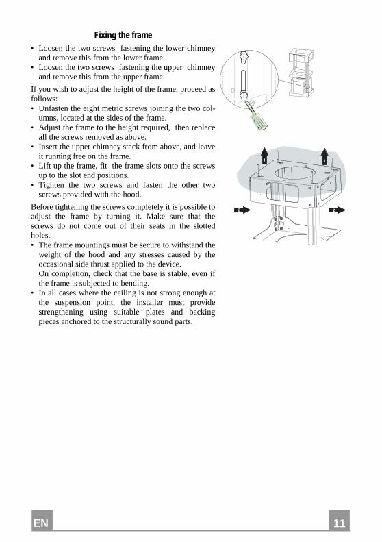
Fixing the frame • Loosen the two screws fastening the lower chimney
and remove this from the lower frame. • Loosen the two screws fastening the upper chimney
and remove this from the upper frame.
If you wish to adjust the height of the frame, proceed as follows: • Unfasten the eight metric screws joining the two col-
umns, located at the sides of the frame. • Adjust the frame to the height required, then replace
all the screws removed as above. • Insert the upper chimney stack from above, and leave
it running free on the frame. • Lift up the frame, fit the frame slots onto the screws
up to the slot end positions. • Tighten the two screws and fasten the other two
screws provided with the hood.
Before tightening the screws completely it is possible to adjust the frame by turning it. Make sure that the screws do not come out of their seats in the slotted holes. • The frame mountings must be secure to withstand the
weight of the hood and any stresses caused by the occasional side thrust applied to the device.
On completion, check that the base is stable, even if the frame is subjected to bending.
• In all cases where the ceiling is not strong enough at the suspension point, the installer must provide strengthening using suitable plates and backing pieces anchored to the structurally sound parts.
� �
� �
EN
12
12
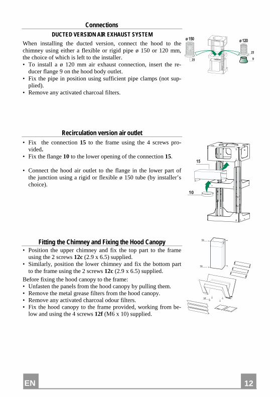
Connections DUCTED VERSION AIR EXHAUST SYSTEM
When installing the ducted version, connect the hood to the chimney using either a flexible or rigid pipe ø 150 or 120 mm, the choice of which is left to the installer. • To install a ø 120 mm air exhaust connection, insert the re-
ducer flange 9 on the hood body outlet. • Fix the pipe in position using sufficient pipe clamps (not sup-
plied). • Remove any activated charcoal filters.
�
����� �����
��
��
Recirculation version air outlet • Fix the connection 15 to the frame using the 4 screws pro-
vided. • Fix the flange 10 to the lower opening of the connection 15. • Connect the hood air outlet to the flange in the lower part of
the junction using a rigid or flexible ø 150 tube (by installer’s choice).
��
�
Fitting the Chimney and Fixing the Hood Canopy • Position the upper chimney and fix the top part to the frame
using the 2 screws 12c (2.9 x 6.5) supplied. • Similarly, position the lower chimney and fix the bottom part
to the frame using the 2 screws 12c (2.9 x 6.5) supplied. Before fixing the hood canopy to the frame: • Unfasten the panels from the hood canopy by pulling them. • Remove the metal grease filters from the hood canopy. • Remove any activated charcoal odour filters. • Fix the hood canopy to the frame provided, working from be-
low and using the 4 screws 12f (M6 x 10) supplied.
���
��
��
EN
13
13
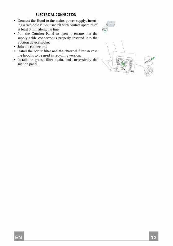
ELECTRICAL CONNECTION
• Connect the Hood to the mains power supply, insert-ing a two-pole cut-out switch with contact aperture of at least 3 mm along the line.
• Pull the Comfort Panel to open it, ensure that the supply cable connector is properly inserted into the Suction device socket
• Join the connectors. • Install the odour filter and the charcoal filter in case
the hood is to be used in recycling version. • Install the grease filter again, and successively the
suction panel.
EN
14
14
USE
� � � � � � � �
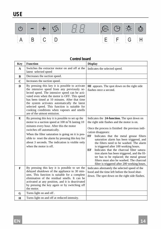
Control board Key Function Display
A Switches the extractor motor on and off at the latest selected speed
Indicates the selected speed.
B Decreases the suction speed.
C Increases the suction speed.
D By pressing this key it is possible to activate the intensive speed from any previously se-lected speed. The intensive speed can be acti-vated even when the motor is OFF. This speed has been timed at 10 minutes. After that time the system activates automatically the latest selected speed. This function is suitable for cooking conditions when vapours and smells are of the utmost emission.
HI appears. The spot down on the right side flashes once a second.
E By pressing this key it is possible to set up the motor to a suction speed at 100 m3/h lasting 10 minutes every hour. After this the motor switches off automatically.
When the filter saturation is going on it is pos-sible to reset the alarm by pressing this key for about 3 seconds. The indication is visible only when the motor is off.
Indicates the 24-function. The spot down on the right side flashes and the motor is on.
Once the process is finished the previous indi-cation disappears: FF Indicates that the metal grease filters
saturation alarm has been triggered, and the filters need to be washed. The alarm is triggered after 100 working hours.
EF Indicates that the charcoal filter satura-tion alarm has been triggered, and the fil-ter has to be replaced; the metal grease filters must also be washed. The charcoal filter is triggered after 200 working hours.
F By pressing this key it is possible to set the delayed shutdown of the appliance to 30 min-utes. This function is suitable for a complete elimination of the residual smells. It can be activated at any position, and it is deactivated by pressing the key again or by switching off the motor.
Indicates alternately the selected speed of the hood and the time left before the hood shut-down. The spot down on the right side flashes.
G Turns light on and off .
H Turns light on and off at reduced intensity.
EN
15
15
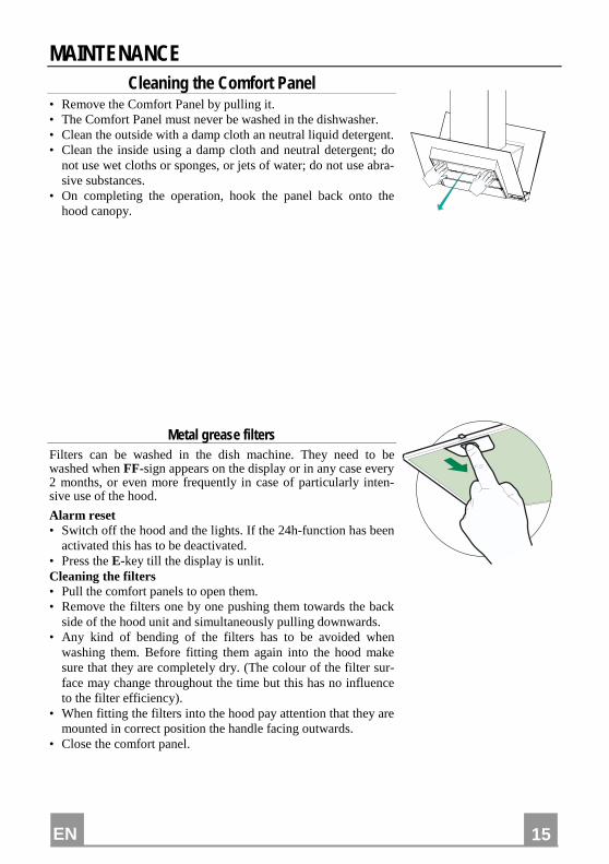
MAINTENANCE Cleaning the Comfort Panel
• Remove the Comfort Panel by pulling it. • The Comfort Panel must never be washed in the dishwasher. • Clean the outside with a damp cloth an neutral liquid detergent. • Clean the inside using a damp cloth and neutral detergent; do
not use wet cloths or sponges, or jets of water; do not use abra-sive substances.
• On completing the operation, hook the panel back onto the hood canopy.
Metal grease filters Filters can be washed in the dish machine. They need to be washed when FF-sign appears on the display or in any case every 2 months, or even more frequently in case of particularly inten-sive use of the hood.
Alarm reset • Switch off the hood and the lights. If the 24h-function has been
activated this has to be deactivated. • Press the E-key till the display is unlit. Cleaning the filters • Pull the comfort panels to open them. • Remove the filters one by one pushing them towards the back
side of the hood unit and simultaneously pulling downwards. • Any kind of bending of the filters has to be avoided when
washing them. Before fitting them again into the hood make sure that they are completely dry. (The colour of the filter sur-face may change throughout the time but this has no influence to the filter efficiency).
• When fitting the filters into the hood pay attention that they are mounted in correct position the handle facing outwards.
• Close the comfort panel.
EN
16
16
Charcoal filter (recycling version) • This filter cannot be washed or regenerated. It must be replaced when the EF appears on the
display or at least once every 4 months.
Activation of the alarm signal • In the recycling version hoods the filter saturation alarm must be activated during the instal-
lation or later. • Switch off the hood and the lights. • Disconnect the hood from the mains supply. • When restoring the connection press and hold B-key. • When releasing the key two rotating rectangles appear on the display. • Within 3 seconds press the B-key until a flashing confirmation appears on the dispaly: • 2 flashes with EF - charcoal filter saturation alarm ACTIVATED • 1 flash with EF - charcoal filter saturation alarm DEACTIVATED.
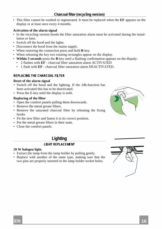
REPLACING THE CHARCOAL FILTER
Reset of the alarm signal • Switch off the hood and the lighting. If the 24h-function has
been activated this has to be deactivated. • Press the E-key until the display is unlit.
Replacing of the filter • Open the comfort panels pulling them downwards. • Remove the metal grease filters. • Remove the saturated charcoal filter by releasing the fixing
hooks • Fit the new filter and fasten it in its correct position. • Put the metal grease filters in their seats. • Close the comfort panels.
Lighting LIGHT REPLACEMENT
20 W halogen light. • Extract the lamp from the lamp holder by pulling gently. • Replace with another of the same type, making sure that the
two pins are properly inserted in the lamp holder socket holes.
IT
17
17
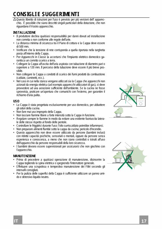
CONSIGLI E SUGGERIMENTI Questo libretto di istruzioni per l'uso è previsto per più versioni dell' apparec-
chio. É possibile che siano descritti singoli particolari della dotazione, che non riguardano il Vostro apparecchio.
INSTALLAZIONE • Il produttore declina qualsiasi responsabilità per danni dovuti ad installazione
non corretta o non conforme alle regole dell’arte. • La distanza minima di sicurezza tra il Piano di cottura e la Cappa deve essere
di 500 mm. • Verificare che la tensione di rete corrisponda a quella riportata nella targhetta
posta all’interno della Cappa. • Per Apparecchi in Classe Ia accertarsi che l’impianto elettrico domestico ga-
rantisca un corretto scarico a terra. • Collegare la Cappa all’uscita dell’aria aspirata con tubazione di diametro pari o
superiore a 120 mm. Il percorso della tubazione deve essere il più breve pos-sibile.
• Non collegare la Cappa a condotti di scarico dei fumi prodotti da combustione (caldaie, caminetti, ecc.).
• Nel caso in cui nella stanza vengano utilizzati sia la Cappa che apparecchi non azionati da energia elettrica (ad esempio apparecchi utilizzatori di gas), si deve provvedere ad una aerazione sufficiente dell’ambiente. Se la cucina ne fosse sprovvista, praticare un’apertura che comunichi con l’esterno, per garantire il richiamo d’aria pulita.
USO • La Cappa è stata progettata esclusivamente per uso domestico, per abbattere
gli odori della cucina. • Non fare mai uso improprio della Cappa. • Non lasciare fiamme libere a forte intensità sotto la Cappa in funzione. • Regolare sempre le fiamme in modo da evitare una evidente fuoriuscita latera-
le delle stesse rispetto al fondo delle pentole. • Controllare le friggitrici durante l’uso: l’olio surriscaldato potrebbe infiammarsi. • Non preparare alimenti flambè sotto la cappa da cucina; pericolo d'incendio. • Questo apparecchio non deve essere utilizzato da persone (bambini inclusi)
con ridotte capacità psichiche, sensoriali o mentali, oppure da persone senza esperienza e conoscenza, a meno che non siano controllati o istruiti all’uso dell’apparecchio da persone responsabili della loro sicurezza.
• I bambini devono essere supervisionati per assicurarsi che non giochino con l’apparecchio.
MANUTENZIONE • Prima di procedere a qualsiasi operazione di manutenzione, disinserire la
Cappa togliendo la spina elettrica o spegnendo l’interruttore generale. • Effettuare una scrupolosa e tempestiva manutenzione dei Filtri secondo gli
intervalli consigliati. • Per la pulizia delle superfici della Cappa è sufficiente utilizzare un panno umi-
do e detersivo liquido neutro.

IT
18
18
CARATTERISTICHE
Ingombro
IT
19
19
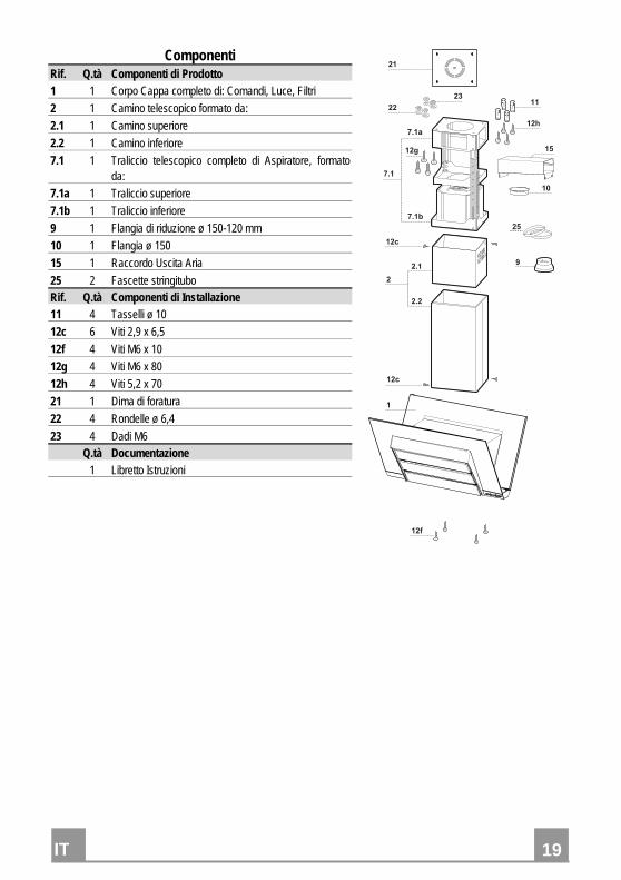
Componenti Rif. Q.tà Componenti di Prodotto 1 1 Corpo Cappa completo di: Comandi, Luce, Filtri
2 1 Camino telescopico formato da:
2.1 1 Camino superiore
2.2 1 Camino inferiore
7.1 1 Traliccio telescopico completo di Aspiratore, formato da:
7.1a 1 Traliccio superiore
7.1b 1 Traliccio inferiore
9 1 Flangia di riduzione ø 150-120 mm
10 1 Flangia ø 150
15 1 Raccordo Uscita Aria
25 2 Fascette stringitubo Rif. Q.tà Componenti di Installazione 11 4 Tasselli ø 10
12c 6 Viti 2,9 x 6,5
12f 4 Viti M6 x 10
12g 4 Viti M6 x 80
12h 4 Viti 5,2 x 70
21 1 Dima di foratura
22 4 Rondelle ø 6,4
23 4 Dadi M6 Q.tà Documentazione 1 Libretto Istruzioni
����
���
����
���
����
�
���
���
��
��
��
��
�
���
��
��
��
�
�
IT
20
20
INSTALLAZIONE
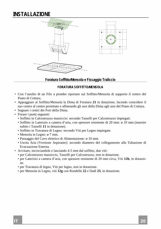
Foratura Soffitto/Mensola e Fissaggio Traliccio
FORATURA SOFFITTO/MENSOLA
• Con l’ausilio di un Filo a piombo riportare sul Soffitto/Mensola di supporto il centro del Piano di Cottura.
• Appoggiare al Soffitto/Mensola la Dima di Foratura 21 in dotazione, facendo coincidere il suo centro al centro proiettato e allineando gli assi della Dima agli assi del Piano di Cottura.
• Segnare i centri dei Fori della Dima. • Forare i punti seguenti: • Soffitto in Calcestruzzo massiccio: secondo Tasselli per Calcestruzzo impiegati. • Soffitto in Laterizio a camera d’aria, con spessore resistente di 20 mm: ø 10 mm (inserire
subito i Tasselli 11 in dotazione). • Soffitto in Travatura di Legno: secondo Viti per Legno impiegate. • Mensola in Legno: ø 7 mm. • Passaggio del Cavo elettrico di Alimentazione: ø 10 mm. • Uscita Aria (Versione Aspirante): secondo diametro del collegamento alla Tubazione di
Evacuazione Esterna. • Avvitare, incrociandole e lasciando 4-5 mm dal soffitto, due viti: • per Calcestruzzo massiccio, Tasselli per Calcestruzzo, non in dotazione. • per Laterizio a camera d’aria, con spessore resistente di 20 mm circa, Viti 12h, in dotazio-
ne. • per Travatura di legno, Viti per legno, non in dotazione. • per Mensola in Legno, viti 12g con Rondelle 22 e Dadi 23, in dotazione.
IT
21
21
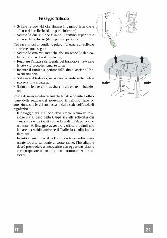
Fissaggio Traliccio
• Svitare le due viti che fissano il camino inferiore e sfilarlo dal traliccio (dalla parte inferiore).
• Svitare le due viti che fissano il camino superiore e sfilarlo dal traliccio (dalla parte superiore).
Nel caso in cui si voglia regolare l’altezza del traliccio procedere come segue: • Svitare le otto viti metriche che uniscono le due co-
lonne, poste ai lati del traliccio; • Regolare l’altezza desiderata del traliccio e riavvitare
le otto viti precedentemente tolte; • Inserire il camino superiore dall’ alto e lasciarlo libe-
ro sul traliccio; • Sollevare il traliccio, incastrare le asole sulle viti e
scorrere fino a battuta; • Stringere le due viti e avvitare le altre due in dotazio-
ne;
Prima di serrare definitivamente le viti è possibile effet-tuare delle regolazioni spostando il traliccio, facendo attenzione che le viti non escano dalla sede dell’asola di regolazione. • Il fissaggio del Traliccio deve essere sicuro in rela-
zione sia al peso della Cappa sia alle sollecitazioni causate da occasionali spinte laterali all’Apparecchio montato. A fissaggio avvenuto verificare quindi che la base sia stabile anche se il Traliccio è sollecitato a flessione.
• In tutti i casi in cui il Soffitto non fosse sufficiente-mente robusto sul punto di sospensione, l’Installatore dovrà provvedere a irrobustirlo con opportune piastre e contropiastre ancorate a parti strutturalmente resi-stenti.
� �
� �
IT
22
22
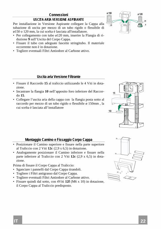
Connessioni USCITA ARIA VERSIONE ASPIRANTE
Per installazione in Versione Aspirante collegare la Cappa alla tubazione di uscita per mezzo di un tubo rigido o flessibile di ø150 o 120 mm, la cui scelta è lasciata all'installatore. • Per collegamento con tubo ø120 mm, inserire la Flangia di ri-
duzione 9 sull’Uscita del Corpo Cappa. • Fissare il tubo con adeguate fascette stringitubo. Il materiale
occorrente non è in dotazione. • Togliere eventuali Filtri Antiodore al Carbone attivo.
�
����� �����
��
��
Uscita aria Versione Filtrante
• Fissare il Raccordo 15 al traliccio utilizzando le 4 Viti in dota-zione.
• Incastrare la flangia 10 nell’apposito foro inferiore del Raccor-do 15.
• Collegare l’uscita aria della cappa con la flangia posta sotto al raccordo per mezzo di un tubo rigido o flessibile ø 150mm , la cui scelta è lasciata all’installatore
��
�
Montaggio Camino e Fissaggio Corpo Cappa • Posizionare il Camino superiore e fissare nella parte superiore
al Traliccio con 2 Viti 12c (2,9 x 6,5) in dotazione. • Analogamente posizionare il Camino inferiore e fissare nella
parte inferiore al Traliccio con 2 Viti 12c (2,9 x 6,5) in dota-zione.
Prima di fissare il Corpo Cappa al Traliccio: • Sganciare i pannelli dal Corpo Cappa tirandoli. • Togliere i Filtri antigrasso dal Corpo Cappa. • Togliere eventuali Filtri Antiodore al Carbone attivo. • Fissare quindi dal sotto, con 4Viti 12f (M6 x 10) in dotazione,
il Corpo Cappa al Traliccio predisposto.
���
��
��
IT
23
23
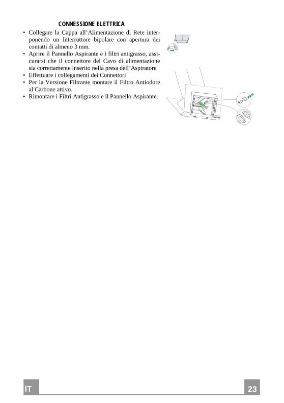
CONNESSIONE ELETTRICA • Collegare la Cappa all’Alimentazione di Rete inter-
ponendo un Interruttore bipolare con apertura dei contatti di almeno 3 mm.
• Aprire il Pannello Aspirante e i filtri antigrasso, assi-curarsi che il connettore del Cavo di alimentazione sia correttamente inserito nella presa dell’Aspiratore
• Effettuare i collegamenti dei Connettori • Per la Versione Filtrante montare il Filtro Antiodore
al Carbone attivo. • Rimontare i Filtri Antigrasso e il Pannello Aspirante.
IT
24
24
USO
� � � � � � � �
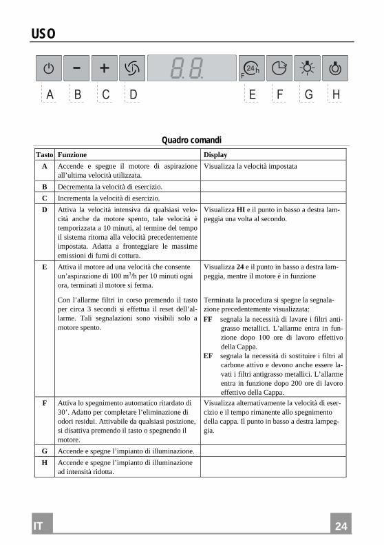
Quadro comandi
Tasto Funzione Display
A Accende e spegne il motore di aspirazione all’ultima velocità utilizzata.
Visualizza la velocità impostata
B Decrementa la velocità di esercizio.
C Incrementa la velocità di esercizio.
D Attiva la velocità intensiva da qualsiasi velo-cità anche da motore spento, tale velocità è temporizzata a 10 minuti, al termine del tempo il sistema ritorna alla velocità precedentemente impostata. Adatta a fronteggiare le massime emissioni di fumi di cottura.
Visualizza HI e il punto in basso a destra lam-peggia una volta al secondo.
E Attiva il motore ad una velocità che consente un’aspirazione di 100 m3/h per 10 minuti ogni ora, terminati il motore si ferma.
Con l’allarme filtri in corso premendo il tasto per circa 3 secondi si effettua il reset dell’al-larme. Tali segnalazioni sono visibili solo a motore spento.
Visualizza 24 e il punto in basso a destra lam-peggia, mentre il motore è in funzione
Terminata la procedura si spegne la segnala-zione precedentemente visualizzata: FF segnala la necessità di lavare i filtri anti-
grasso metallici. L’allarme entra in fun-zione dopo 100 ore di lavoro effettivo della Cappa.
EF segnala la necessità di sostituire i filtri al carbone attivo e devono anche essere la-vati i filtri antigrasso metallici. L’allarme entra in funzione dopo 200 ore di lavoro effettivo della Cappa.
F Attiva lo spegnimento automatico ritardato di 30’. Adatto per completare l’eliminazione di odori residui. Attivabile da qualsiasi posizione, si disattiva premendo il tasto o spegnendo il motore.
Visualizza alternativamente la velocità di eser-cizio e il tempo rimanente allo spegnimento della cappa. Il punto in basso a destra lampeg-gia.
G Accende e spegne l’impianto di illuminazione.
H Accende e spegne l’impianto di illuminazione ad intensità ridotta.
IT
25
25
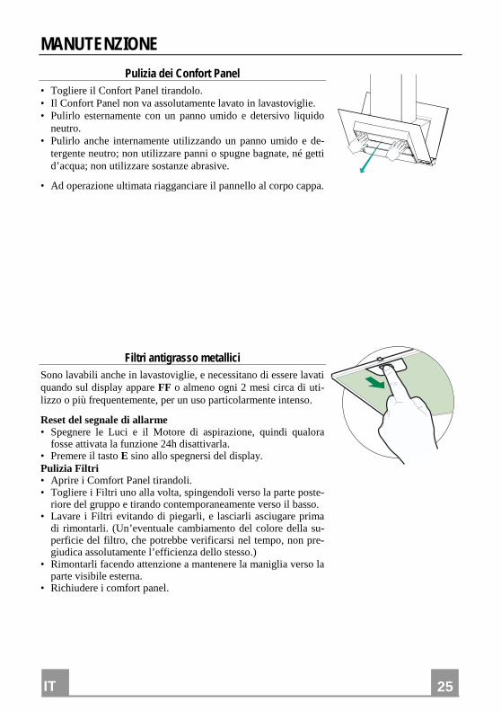
MANUTENZIONE
Pulizia dei Confort Panel • Togliere il Confort Panel tirandolo. • Il Confort Panel non va assolutamente lavato in lavastoviglie. • Pulirlo esternamente con un panno umido e detersivo liquido
neutro. • Pulirlo anche internamente utilizzando un panno umido e de-
tergente neutro; non utilizzare panni o spugne bagnate, né getti d’acqua; non utilizzare sostanze abrasive.
• Ad operazione ultimata riagganciare il pannello al corpo cappa.
Filtri antigrasso metallici Sono lavabili anche in lavastoviglie, e necessitano di essere lavati quando sul display appare FF o almeno ogni 2 mesi circa di uti-lizzo o più frequentemente, per un uso particolarmente intenso.
Reset del segnale di allarme • Spegnere le Luci e il Motore di aspirazione, quindi qualora
fosse attivata la funzione 24h disattivarla. • Premere il tasto E sino allo spegnersi del display. Pulizia Filtri • Aprire i Comfort Panel tirandoli. • Togliere i Filtri uno alla volta, spingendoli verso la parte poste-
riore del gruppo e tirando contemporaneamente verso il basso. • Lavare i Filtri evitando di piegarli, e lasciarli asciugare prima
di rimontarli. (Un’eventuale cambiamento del colore della su-perficie del filtro, che potrebbe verificarsi nel tempo, non pre-giudica assolutamente l’efficienza dello stesso.)
• Rimontarli facendo attenzione a mantenere la maniglia verso la parte visibile esterna.
• Richiudere i comfort panel.
IT
26
26
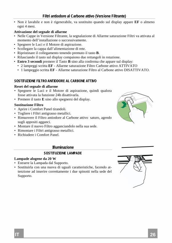
Filtri antiodore al Carbone attivo (Versione Filtrante) • Non è lavabile e non è rigenerabile, va sostituito quando sul display appare EF o almeno
ogni 4 mesi.
Attivazione del segnale di allarme • Nelle Cappe in Versione Filtrante, la segnalazione di Allarme saturazione Filtri va attivata al
momento dell’installazione o successivamente. • Spegnere le Luci e il Motore di aspirazione. • Scollegare la cappa dall’alimentazione di rete. • Ripristinare il collegamento tenendo premuto il tasto B. • Rilasciando il tasto sul display compaiono due rettangoli in rotazione. • Entro 3 secondi premere il Tasto B sino alla conferma che appare sul display:
• 2 lampeggi scritta EF - Allarme saturazione Filtro Carbone attivo ATTIVATO • 1 lampeggio scritta EF - Allarme saturazione Filtro al Carbone attivo DISATTIVATO.
SOSTITUZIONE FILTRO ANTIODORE AL CARBONE ATTIVO
Reset del segnale di allarme • Spegnere le Luci e il Motore di aspirazione, quindi qualora
fosse attivata la funzione 24h disattivarla. • Premere il tasto E sino allo spegnersi del display.
Sostituzione Filtro • Aprire i Comfort Panel tirandoli. • Togliere i Filtri antigrasso metallici. • Rimuovere il Filtro antiodore al Carbone attivo saturo, agendo
sugli appositi agganci. • Montare il nuovo Filtro agganciandolo nella sua sede. • Rimontare i Filtri antigrasso metallici. • Richiudere i Comfort Panel.
Illuminazione
SOSTITUZIONE LAMPADE
Lampade alogene da 20 W • Estrarre la Lampada dal Supporto. • Sostituirla con una nuova di uguali caratteristiche, facendo at-
tenzione ad inserire correttamente i due spinotti nella sede del Supporto.
FR
27
27
CONSEILS ET SUGGESTIONS La présente notice d'emploi vaut pour plusieurs versions de l'appareil. Elle peut contenir des descriptions d'accessoires ne figurant pas dans votre ap-
pareil.
INSTALLATION • Le fabricant décline toute responsabilité en cas de dommage dû à une installation
non correcte ou non conforme aux règles de l’art. • La distance minimale de sécurité entre le plan de cuisson et la hotte doit être de
500 mm au moins. • Vérifier que la tension du secteur correspond à la valeur qui figure sur la pla-
quette apposée à l’intérieur de la hotte. • Pour les Appareils appartenant à la Ière Classe, veiller à ce que la mise à la terre
de l’installation électrique domestique ait été effectuée conformément aux nor-mes en vigueur.
• Connecter la hotte à la sortie d’air aspiré à l’aide d’une tuyauterie d’un diamètre égal ou supérieur à 120 mm. Le parcours de la tuyauterie doit être le plus court possible.
• Eviter de connecter la hotte à des conduites d’évacuation de fumées issues d’une combustion tel que (Chaudière, cheminée, etc…).
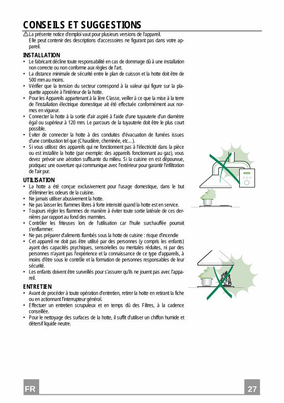
• Si vous utilisez des appareils qui ne fonctionnent pas à l’électricité dans la pièce ou est installée la hotte (par exemple: des appareils fonctionnant au gaz), vous devez prévoir une aération suffisante du milieu. Si la cuisine en est dépourvue, pratiquez une ouverture qui communique avec l’extérieur pour garantir l’infiltration de l’air pur.
UTILISATION • La hotte a été conçue exclusivement pour l’usage domestique, dans le but
d’éliminer les odeurs de la cuisine. • Ne jamais utiliser abusivement la hotte. • Ne pas laisser les flammes libres à forte intensité quand la hotte est en service. • Toujours régler les flammes de manière à éviter toute sortie latérale de ces der-
nières par rapport au fond des marmites. • Contrôler les friteuses lors de l’utilisation car l’huile surchauffée pourrait
s’enflammer. • Ne pas préparer d’aliments flambés sous la hotte de cuisine : risque d’incendie • Cet appareil ne doit pas être utilisé par des personnes (y compris les enfants)
ayant des capacités psychiques, sensorielles ou mentales réduites, ni par des personnes n’ayant pas l’expérience et la connaissance de ce type d’appareils, à moins d'être sous le contrôle et la formation de personnes responsables de leur sécurité.
• Les enfants doivent être surveillés pour s'assurer qu'ils ne jouent pas avec l'appa-reil.
ENTRETIEN • Avant de procéder à toute opération d’entretien, retirer la hotte en retirant la fiche
ou en actionnant l’interrupteur général. • Effectuer un entretien scrupuleux et en temps dû des Filtres, à la cadence
conseillée. • Pour le nettoyage des surfaces de la hotte, il suffit d’utiliser un chiffon humide et
détersif liquide neutre.
FR
28
28
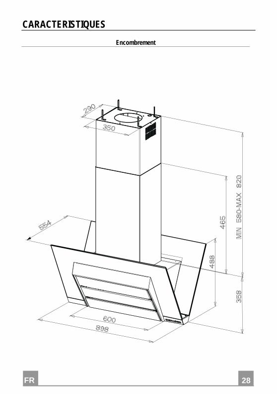
CARACTERISTIQUES
Encombrement
FR
29
29
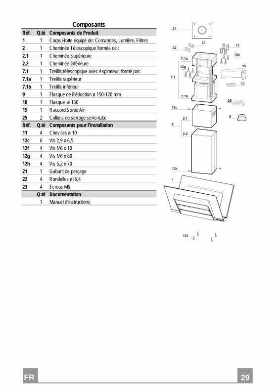
Composants Réf. Q.té Composants de Produit 1 1 Corps Hotte équipé de: Comandes, Lumière, Filtres
2 1 Cheminée Télescopique formée de :
2.1 1 Cheminée Supérieure
2.2 1 Cheminée Inférieure
7.1 1 Treillis télescopique avec Aspirateur, formé par:
7.1a 1 Treillis supérieur
7.1b 1 Treillis inférieur
9 1 Flasque de Réduction ø 150-120 mm
10 1 Flasque ø 150
15 1 Raccord Sortie Air
25 2 Colliers de serrage serre-tube Réf. Q.té Composants pour l’installation 11 4 Chevilles ø 10
12c 6 Vis 2,9 x 6,5
12f 4 Vis M6 x 10
12g 4 Vis M6 x 80
12h 4 Vis 5,2 x 70
21 1 Gabarit de perçage
22 4 Rondelles øi 6,4
23 4 Écrous M6 Q.té Documentation 1 Manuel d’instructions
����
���
����
���
����
�
���
���
��
��
��
��
�
���
��
��
��
�
�
FR
30
30
INSTALLATION
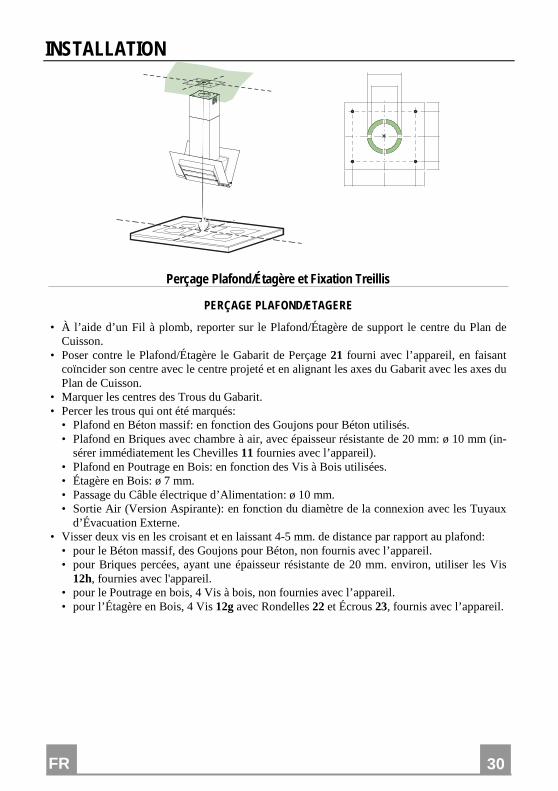
Perçage Plafond/Étagère et Fixation Treillis
PERÇAGE PLAFOND/ETAGERE
• À l’aide d’un Fil à plomb, reporter sur le Plafond/Étagère de support le centre du Plan de Cuisson.
• Poser contre le Plafond/Étagère le Gabarit de Perçage 21 fourni avec l’appareil, en faisant coïncider son centre avec le centre projeté et en alignant les axes du Gabarit avec les axes du Plan de Cuisson.
• Marquer les centres des Trous du Gabarit. • Percer les trous qui ont été marqués:
• Plafond en Béton massif: en fonction des Goujons pour Béton utilisés. • Plafond en Briques avec chambre à air, avec épaisseur résistante de 20 mm: ø 10 mm (in-
sérer immédiatement les Chevilles 11 fournies avec l’appareil). • Plafond en Poutrage en Bois: en fonction des Vis à Bois utilisées. • Étagère en Bois: ø 7 mm. • Passage du Câble électrique d’Alimentation: ø 10 mm. • Sortie Air (Version Aspirante): en fonction du diamètre de la connexion avec les Tuyaux
d’Évacuation Externe. • Visser deux vis en les croisant et en laissant 4-5 mm. de distance par rapport au plafond:
• pour le Béton massif, des Goujons pour Béton, non fournis avec l’appareil. • pour Briques percées, ayant une épaisseur résistante de 20 mm. environ, utiliser les Vis
12h, fournies avec l'appareil. • pour le Poutrage en bois, 4 Vis à bois, non fournies avec l’appareil. • pour l’Étagère en Bois, 4 Vis 12g avec Rondelles 22 et Écrous 23, fournis avec l’appareil.
FR
31
31
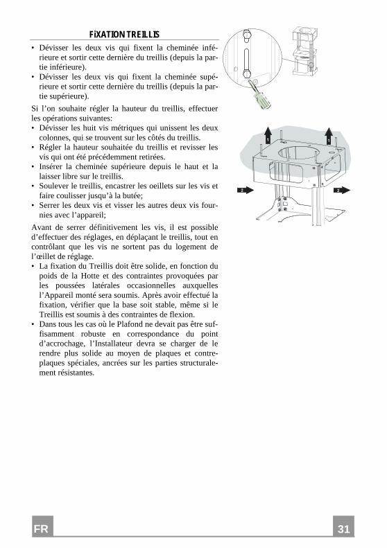
FiXATION TREILLIS • Dévisser les deux vis qui fixent la cheminée infé-
rieure et sortir cette dernière du treillis (depuis la par-tie inférieure).
• Dévisser les deux vis qui fixent la cheminée supé-rieure et sortir cette dernière du treillis (depuis la par-tie supérieure).
Si l’on souhaite régler la hauteur du treillis, effectuer les opérations suivantes: • Dévisser les huit vis métriques qui unissent les deux
colonnes, qui se trouvent sur les côtés du treillis. • Régler la hauteur souhaitée du treillis et revisser les
vis qui ont été précédemment retirées. • Insérer la cheminée supérieure depuis le haut et la
laisser libre sur le treillis. • Soulever le treillis, encastrer les oeillets sur les vis et
faire coulisser jusqu’à la butée; • Serrer les deux vis et visser les autres deux vis four-
nies avec l’appareil;
Avant de serrer définitivement les vis, il est possible d’effectuer des réglages, en déplaçant le treillis, tout en contrôlant que les vis ne sortent pas du logement de l’œillet de réglage. • La fixation du Treillis doit être solide, en fonction du
poids de la Hotte et des contraintes provoquées par les poussées latérales occasionnelles auxquelles l’Appareil monté sera soumis. Après avoir effectué la fixation, vérifier que la base soit stable, même si le Treillis est soumis à des contraintes de flexion.
• Dans tous les cas où le Plafond ne devait pas être suf-fisamment robuste en correspondance du point d’accrochage, l’Installateur devra se charger de le rendre plus solide au moyen de plaques et contre-plaques spéciales, ancrées sur les parties structurale-ment résistantes.
� �
� �
FR
32
32
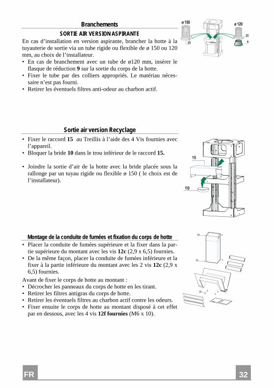
Branchements SORTIE AIR VERSION ASPIRANTE
En cas d’installation en version aspirante, brancher la hotte à la tuyauterie de sortie via un tube rigide ou flexible de ø 150 ou 120 mm, au choix de l’installateur. • En cas de branchement avec un tube de ø120 mm, insérer le
flasque de réduction 9 sur la sortie du corps de la hotte. • Fixer le tube par des colliers appropriés. Le matériau néces-
saire n’est pas fourni. • Retirer les éventuels filtres anti-odeur au charbon actif.
�
����� �����
��
��
Sortie air version Recyclage • Fixer le raccord 15 au Treillis à l’aide des 4 Vis fournies avec
l’appareil. • Bloquer la bride 10 dans le trou inférieur de le raccord 15. • Joindre la sortie d’air de la hotte avec la bride placée sous la
rallonge par un tuyau rigide ou flexible ø 150 ( le choix est de l’installateur).
��
�
Montage de la conduite de fumées et fixation du corps de hotte • Placer la conduite de fumées supérieure et la fixer dans la par-
tie supérieure du montant avec les vis 12c (2,9 x 6,5) fournies. • De la même façon, placer la conduite de fumées inférieure et la
fixer à la partie inférieure du montant avec les 2 vis 12c (2,9 x 6,5) fournies.
Avant de fixer le corps de hotte au montant : • Décrocher les panneaux du corps de hotte en les tirant. • Retirer les filtres antigras du corps de hotte. • Retirer les éventuels filtres au charbon actif contre les odeurs. • Fixer ensuite le corps de hotte au montant disposé à cet effet
par en dessous, avec les 4 vis 12f fournies (M6 x 10).
���
��
��
FR
33
33
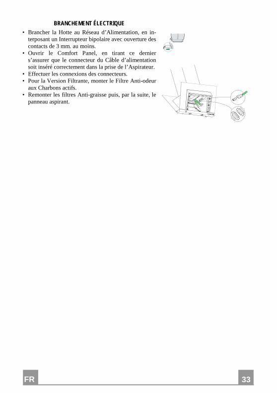
BRANCHEMENT ÉLECTRIQUE • Brancher la Hotte au Réseau d’Alimentation, en in-
terposant un Interrupteur bipolaire avec ouverture des contacts de 3 mm. au moins.
• Ouvrir le Comfort Panel, en tirant ce dernier s’assurer que le connecteur du Câble d’alimentation soit inséré correctement dans la prise de l’Aspirateur.
• Effectuer les connexions des connecteurs. • Pour la Version Filtrante, monter le Filtre Anti-odeur
aux Charbons actifs. • Remonter les filtres Anti-graisse puis, par la suite, le
panneau aspirant.
FR
34
34
UTILISATION
� � � � � � � �
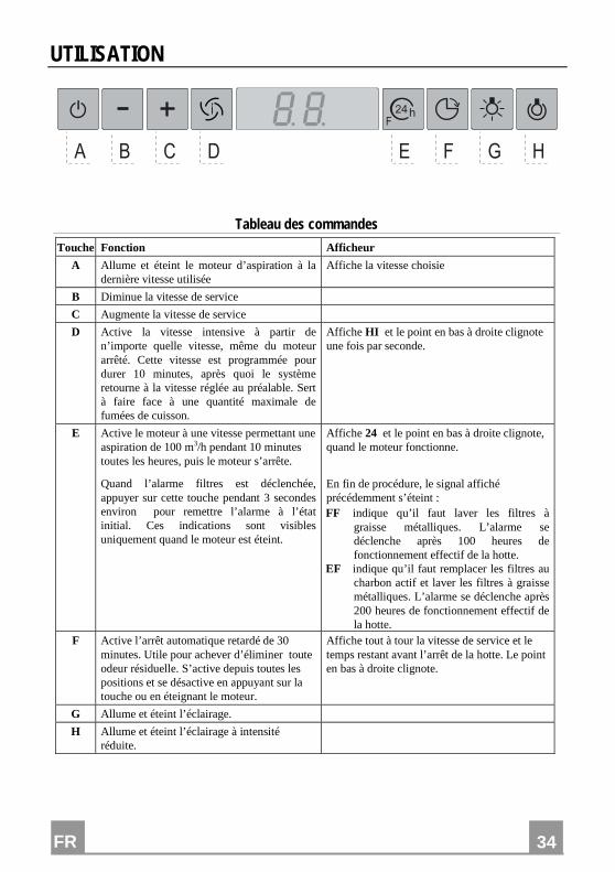
Tableau des commandes
Touche Fonction Afficheur
A Allume et éteint le moteur d’aspiration à la dernière vitesse utilisée
Affiche la vitesse choisie
B Diminue la vitesse de service
C Augmente la vitesse de service
D Active la vitesse intensive à partir de n’importe quelle vitesse, même du moteur arrêté. Cette vitesse est programmée pour durer 10 minutes, après quoi le système retourne à la vitesse réglée au préalable. Sert à faire face à une quantité maximale de fumées de cuisson.
Affiche HI et le point en bas à droite clignote une fois par seconde.
E Active le moteur à une vitesse permettant une aspiration de 100 m3/h pendant 10 minutes toutes les heures, puis le moteur s’arrête.
Quand l’alarme filtres est déclenchée, appuyer sur cette touche pendant 3 secondes environ pour remettre l’alarme à l’état initial. Ces indications sont visibles uniquement quand le moteur est éteint.
Affiche 24 et le point en bas à droite clignote, quand le moteur fonctionne.
En fin de procédure, le signal affiché précédemment s’éteint : FF indique qu’il faut laver les filtres à
graisse métalliques. L’alarme se déclenche après 100 heures de fonctionnement effectif de la hotte.
EF indique qu’il faut remplacer les filtres au charbon actif et laver les filtres à graisse métalliques. L’alarme se déclenche après 200 heures de fonctionnement effectif de la hotte.
F Active l’arrêt automatique retardé de 30 minutes. Utile pour achever d’éliminer toute odeur résiduelle. S’active depuis toutes les positions et se désactive en appuyant sur la touche ou en éteignant le moteur.
Affiche tout à tour la vitesse de service et le temps restant avant l’arrêt de la hotte. Le point en bas à droite clignote.
G Allume et éteint l’éclairage.
H Allume et éteint l’éclairage à intensité réduite.
FR
35
35
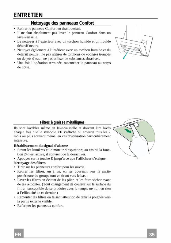
ENTRETIEN Nettoyage des panneaux Confort
• Retirer le panneau Confort en tirant dessus. • Il ne faut absolument pas laver le panneau Confort dans un
lave-vaisselle. • Le nettoyer à l’extérieur avec un torchon humide et un liquide
détersif neutre. • Nettoyer également à l’intérieur avec un torchon humide et du
détersif neutre ; ne pas utiliser de torchons ou éponges trempés ou de jets d’eau ; ne pas utiliser de substances abrasives.
• Une fois l’opération terminée, raccrocher le panneau au corps de hotte.
Filtres à graisse métalliques Ils sont lavables même en lave-vaisselle et doivent être lavés chaque fois que le symbole FF s’affiche ou environ tous les 2 mois ou plus souvent même, en cas d’utilisation particulièrement intensive.
Rétablissement du signal d’alarme • Eteint les lumières et le moteur d’aspiration; au cas où la fonc-
tion 24h est active, il convient de la désactiver. • Appuyer sur la touche E jusqu’à ce que l’afficheur s’éteigne. Nettoyage des filtres • Tirer sur les panneaux confort pour les ouvrir. • Retirer les filtres, un à un, en les poussant vers la partie
postérieure du groupe tout en tirant vers le bas. • Laver les filtres en évitant de les plier, et les faire sécher avant
de les remonter. (Tout changement de couleur sur la surface du filtre, susceptible de se produire avec le temps, ne nuit en rien à l’efficacité de ce dernier.)
• Remonter les filtres en faisant attention de tenir la poignée vers la partie externe visible.
• Refermer les panneaux confort.
FR
36
36
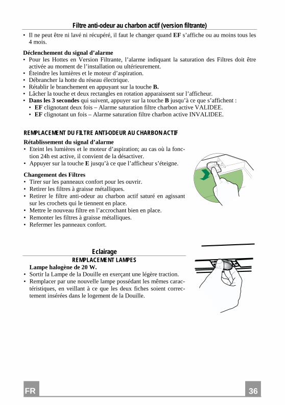
Filtre anti-odeur au charbon actif (version filtrante) • Il ne peut être ni lavé ni récupéré, il faut le changer quand EF s’affiche ou au moins tous les
4 mois.
Déclenchement du signal d’alarme • Pour les Hottes en Version Filtrante, l’alarme indiquant la saturation des Filtres doit être
activée au moment de l’installation ou ultérieurement. • Éteindre les lumières et le moteur d’aspiration. • Débrancher la hotte du réseau électrique. • Rétablir le branchement en appuyant sur la touche B. • Lâcher la touche et deux rectangles en rotation apparaissent sur l’afficheur. • Dans les 3 secondes qui suivent, appuyer sur la touche B jusqu’à ce que s’affichent :
• EF clignotant deux fois – Alarme saturation filtre charbon active VALIDEE. • EF clignotant un fois – Alarme saturation filtre charbon active INVALIDEE.
REMPLACEMENT DU FILTRE ANTI-ODEUR AU CHARBON ACTIF
Rétablissement du signal d’alarme • Eteint les lumières et le moteur d’aspiration; au cas où la fonc-
tion 24h est active, il convient de la désactiver. • Appuyer sur la touche E jusqu’à ce que l’afficheur s’éteigne.
Changement des Filtres • Tirer sur les panneaux confort pour les ouvrir. • Retirer les filtres à graisse métalliques. • Retirer le filtre anti-odeur au charbon actif saturé en agissant
sur les crochets qui le tiennent en place. • Mettre le nouveau filtre en l’accrochant bien en place. • Remonter les filtres à graisse métalliques. • Refermer les panneaux confort.
Eclairage REMPLACEMENT LAMPES
Lampe halogène de 20 W. • Sortir la Lampe de la Douille en exerçant une légère traction. • Remplacer par une nouvelle lampe possédant les mêmes carac-
téristiques, en veillant à ce que les deux fiches soient correc-tement insérées dans le logement de la Douille.
DE
37
37
EMPFEHLUNGEN UND HINWEISE Diese Gebrauchsanleitung gilt für mehrere Geräte-Ausführungen. Es ist möglich, dass einzelne Ausstattungsmerkmale beschrieben sind, die nicht auf Ihr
Gerät zutreffen.
MONTAGE • Das Gerät darf nur vom Fachpersonal angeschlossen werden. • Der Hersteller haftet nicht für Schäden, die auf eine fehlerhafte und unsachgemäße Mon-
tage zurückzuführen sind. • Der minimale Sicherheitsabstand zwischen Kochmulde und Haube muss 500 mm betra-
gen. • Prüfen, ob die Netzspannung mit dem Wert auf dem im Haubeninneren angebrachten
Schild übereinstimmt. • Bei Geräten der Klasse I ist sicherzustellen, dass die elektrische Anlage des Wohnhauses
über eine vorschriftsmäßige Erdung verfügt. • Das Anschlussrohr der Haube zur Luftaustrittsöffnung sollte möglicherweise einen
Durchmesser von 150 mm aufweisen. Der Rohrverlauf muss so kurz wie möglich sein. • Die Haube darf an keine Entlüftungsschächte angeschlossen werden, in die Verbren-
nungsgase (Heizkessel, Kamine usw.) geleitet werden. • Werden im Raum außer der Dunstabzugshaube andere, nicht elektrisch betriebene (z.B.
gasbetriebene) Geräte verwendet, muss für eine ausreichende Belüftung gesorgt werden. Sollte die Küche diesbezüglich nicht entsprechen, ist an einer Aussenwand eine Öffnung anzubringen, die Frischluftzufuhr gewährleistet.
BEDIENUNG • Die Dunstabzugshaube ist ausschließlich zum Einsatz im privaten Haushalt und zur Be-
seitigung von Küchengerüchen vorgesehen. • Bei unsachgemäßer Benutzung wird keine Haftung übernommen. Achtung! Große Flammen bei eingeschalteter Haube niemals unbedeckt lassen. • Die Intensivität der Flamme ist so zu regulieren, dass sie den Topfboden nicht überragt.
Achtung! Frittiergeräte müssen während des Gebrauchs stets beaufsichtigt wer-den: Überhitztes Öl kann sich entzünden.
• Keine flambierten Speisen unter der Abzugshaube zubereiten: Brandgefahr. • Dieses Gerät darf nicht von Personen, auch Kindern, mit verminderten psychischen,
sensorischen und geistigern Fähigkeiten, oder von Personen ohne Erfahrung und Kennt-nisse benutzt werden, sofern sie nicht von für ihre Sicherheit verantwortlichen Personen beaufsichtigt und beim Gebrauch des Geräts angeleitet werden.
• Kinder dürfen sich nicht unbeaufsichtigt in der Nähe des Geräts aufhalten und auf keinen Fall mit dem Gerät spielen.
WARTUNG • Bevor Wartungsarbeiten durchgeführt werden, muss die Stromzufuhr zur Haube unter-
brochen werden, indem der Stecker gezogen oder der Hauptschalter abgeschaltet wird. • Bei der Filterwartung müssen die vom Hersteller empfohlenen Zeiträume zum Austau-
schen der Filter genauestens eingehalten werden. • Zur Reinigung der Haubenflächen Wir empfehlen ein feuchtes Tuch und ein mildes Flüs-
sigreinigungsmittel. • Bitte keine Reinigungsmittel mit Scheuermittel verwenden. Die Oberfläche wird damit
verkratzt.
DE
38
38
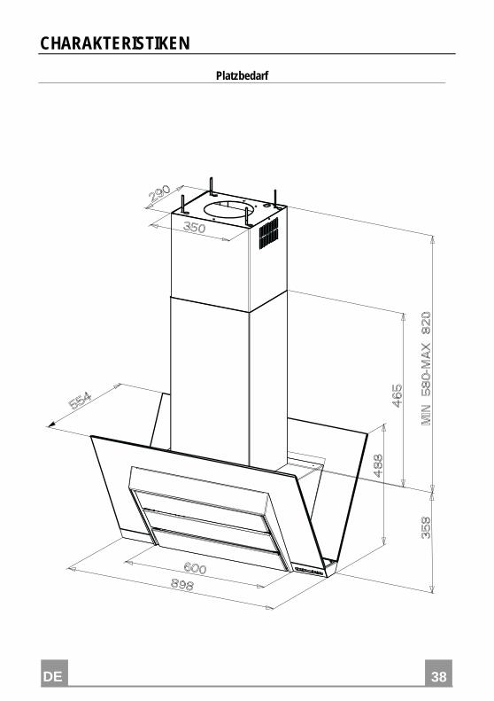
CHARAKTERISTIKEN
Platzbedarf
DE
39
39
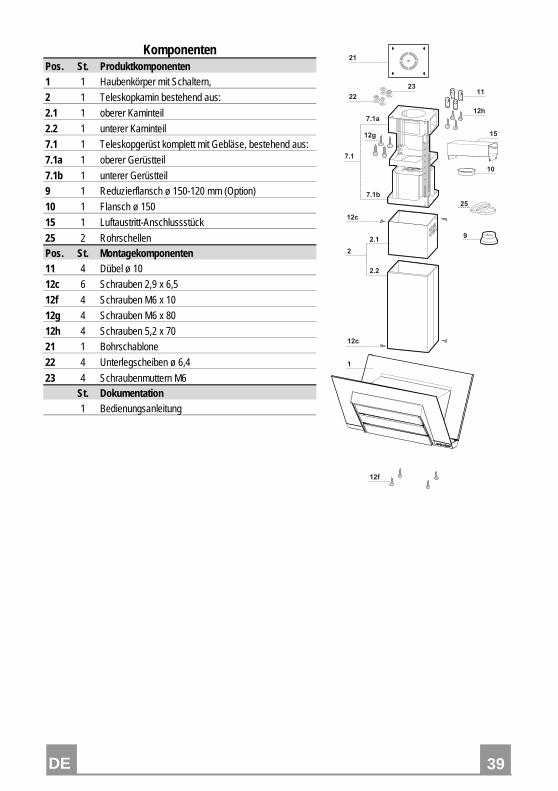
Komponenten Pos. St. Produktkomponenten 1 1 Haubenkörper mit Schaltern,
2 1 Teleskopkamin bestehend aus:
2.1 1 oberer Kaminteil
2.2 1 unterer Kaminteil
7.1 1 Teleskopgerüst komplett mit Gebläse, bestehend aus:
7.1a 1 oberer Gerüstteil
7.1b 1 unterer Gerüstteil
9 1 Reduzierflansch ø 150-120 mm (Option)
10 1 Flansch ø 150
15 1 Luftaustritt-Anschlussstück
25 2 Rohrschellen Pos. St. Montagekomponenten 11 4 Dübel ø 10
12c 6 Schrauben 2,9 x 6,5
12f 4 Schrauben M6 x 10
12g 4 Schrauben M6 x 80
12h 4 Schrauben 5,2 x 70
21 1 Bohrschablone
22 4 Unterlegscheiben ø 6,4
23 4 Schraubenmuttern M6 St. Dokumentation 1 Bedienungsanleitung
����
���
����
���
����
�
���
���
��
��
��
��
�
���
��
��
��
�
�
DE
40
40
MONTAGE
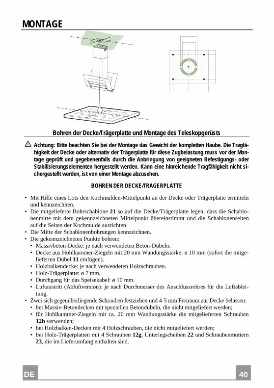
Bohren der Decke/Trägerplatte und Montage des Teleskopgerüsts
Achtung: Bitte beachten Sie bei der Montage das Gewicht der kompletten Haube. Die Tragfä-higkeit der Decke oder alternativ der Trägerplatte für diese Zugbelastung muss vor der Mon-tage geprüft und gegebenenfalls durch die Anbringung von geeigneten Befestigungs- oder Stabilisierungselementen hergestellt werden. Kann eine hinreichende Tragfähigkeit nicht si-chergestellt werden, ist von einer Montage abzusehen.
BOHREN DER DECKE/TRAGERPLATTE
• Mit Hilfe eines Lots den Kochmulden-Mittelpunkt an der Decke oder Trägerplatte ermitteln und kennzeichnen.
• Die mitgelieferte Bohrschablone 21 so auf die Decke/Trägerplatte legen, dass die Schablo-nenmitte mit dem gekennzeichneten Mittelpunkt übereinstimmt und die Schablonenseiten auf die Seiten der Kochmulde ausrichten.
• Die Mitte der Schablonenbohrungen kennzeichnen. • Die gekennzeichneten Punkte bohren:
• Massivbeton-Decke: je nach verwendeten Beton-Dübeln. • Decke aus Hohlkammer-Ziegeln mit 20 mm Wandungsstärke: ø 10 mm (sofort die mitge-
lieferten Dübel 11 einfügen). • Holzbalkendecke: je nach verwendeten Holzschrauben. • Holz-Trägerplatte: ø 7 mm. • Durchgang für das Speisekabel: ø 10 mm. • Luftaustritt (Abluftversion): je nach Durchmesser des Anschlussrohres für die Luftablei-
tung. • Zwei sich gegenüberliegende Schrauben festziehen und 4-5 mm Freiraum zur Decke belassen:
• bei Massiv-Betondecken mit speziellen Betondübeln, die nicht mitgeliefert werden; • für Hohlkammer-Ziegeln mit ca. 20 mm Wandungsstärke die mitgelieferten Schrauben
12h verwenden; • bei Holzbalken-Decken mit 4 Holzschrauben, die nicht mitgeliefert werden; • bei Holz-Trägerplatten mit 4 Schrauben 12g, Unterlegscheiben 22 und Schraubenmuttern
23, die im Lieferumfang enthalten sind.
DE
41
41
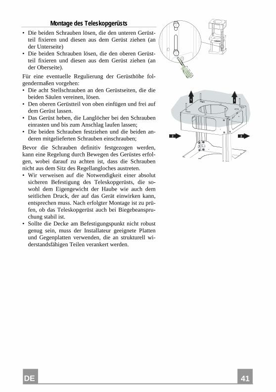
Montage des Teleskopgerüsts • Die beiden Schrauben lösen, die den unteren Gerüst-
teil fixieren und diesen aus dem Gerüst ziehen (an der Unterseite)
• Die beiden Schrauben lösen, die den oberen Gerüst-teil fixieren und diesen aus dem Gerüst ziehen (an der Oberseite).
Für eine eventuelle Regulierung der Gerüsthöhe fol-gendermaßen vorgehen: • Die acht Stellschrauben an den Gerüstseiten, die die
beiden Säulen vereinen, lösen. • Den oberen Gerüstteil von oben einfügen und frei auf
dem Gerüst lassen. • Das Gerüst heben, die Langlöcher bei den Schrauben
einrasten und bis zum Anschlag laufen lassen; • Die beiden Schrauben festziehen und die beiden an-
deren mitgelieferten Schrauben einschrauben;
Bevor die Schrauben definitiv festgezogen werden, kann eine Regelung durch Bewegen des Gerüstes erfol-gen, wobei darauf zu achten ist, dass die Schrauben nicht aus dem Sitz des Regellangloches austreten. • Wir verweisen auf die Notwendigkeit einer absolut
sicheren Befestigung des Teleskopgerüsts, die so-wohl dem Eigengewicht der Haube wie auch dem seitlichen Druck, der auf das Gerät einwirken kann, entsprechen muss. Nach erfolgter Montage ist zu prü-fen, ob das Teleskopgerüst auch bei Biegebeanspru-chung stabil ist.
• Sollte die Decke am Befestigungspunkt nicht robust genug sein, muss der Installateur geeignete Platten und Gegenplatten verwenden, die an strukturell wi-derstandsfähigen Teilen verankert werden.
� �
� �
DE
42
42
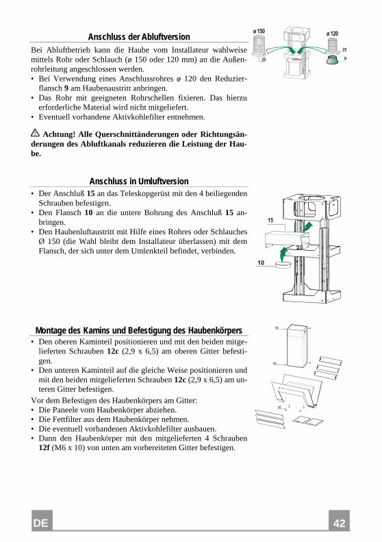
Anschluss der Abluftversion Bei Abluftbetrieb kann die Haube vom Installateur wahlweise mittels Rohr oder Schlauch (ø 150 oder 120 mm) an die Außen-rohrleitung angeschlossen werden. • Bei Verwendung eines Anschlussrohres ø 120 den Reduzier-
flansch 9 am Haubenaustritt anbringen. • Das Rohr mit geeigneten Rohrschellen fixieren. Das hierzu
erforderliche Material wird nicht mitgeliefert. • Eventuell vorhandene Aktivkohlefilter entnehmen.
Achtung! Alle Querschnittänderungen oder Richtungsän-derungen des Abluftkanals reduzieren die Leistung der Hau-be.
�
����� �����
��
��
Anschluss in Umluftversion • Der Anschluß 15 an das Teleskopgerüst mit den 4 beiliegenden
Schrauben befestigen. • Den Flansch 10 an die untere Bohrung des Anschluß 15 an-
bringen. • Den Haubenluftaustritt mit Hilfe eines Rohres oder Schlauches
Ø 150 (die Wahl bleibt dem Installateur überlassen) mit dem Flansch, der sich unter dem Umlenkteil befindet, verbinden.
��
�
Montage des Kamins und Befestigung des Haubenkörpers • Den oberen Kaminteil positionieren und mit den beiden mitge-
lieferten Schrauben 12c (2,9 x 6,5) am oberen Gitter befesti-gen.
• Den unteren Kaminteil auf die gleiche Weise positionieren und mit den beiden mitgelieferten Schrauben 12c (2,9 x 6,5) am un-teren Gitter befestigen.
Vor dem Befestigen des Haubenkörpers am Gitter: • Die Paneele vom Haubenkörper abziehen. • Die Fettfilter aus dem Haubenkörper nehmen. • Die eventuell vorhandenen Aktivkohlefilter ausbauen. • Dann den Haubenkörper mit den mitgelieferten 4 Schrauben
12f (M6 x 10) von unten am vorbereiteten Gitter befestigen.
���
��
��
DE
43
43
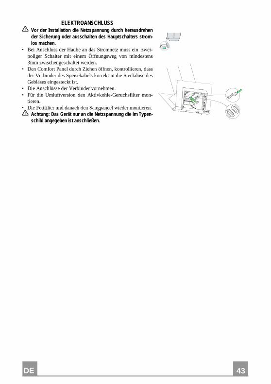
ELEKTROANSCHLUSS Vor der Installation die Netzspannung durch herausdrehen der Sicherung oder ausschalten des Hauptschalters strom-los machen.
• Bei Anschluss der Haube an das Stromnetz muss ein zwei-poliger Schalter mit einem Öffnungsweg von mindestens 3mm zwischengeschaltet werden.
• Den Comfort Panel durch Ziehen öffnen, kontrollieren, dass der Verbinder des Speisekabels korrekt in die Steckdose des Gebläses eingesteckt ist.
• Die Anschlüsse der Verbinder vornehmen. • Für die Umluftversion den Aktivkohle-Geruchsfilter mon-
tieren. • Die Fettfilter und danach den Saugpaneel wieder montieren.
Achtung: Das Gerät nur an die Netzspannung die im Typen-schild angegeben ist anschließen.
DE
44
44
BEDIENUNG
� � � � � � � �
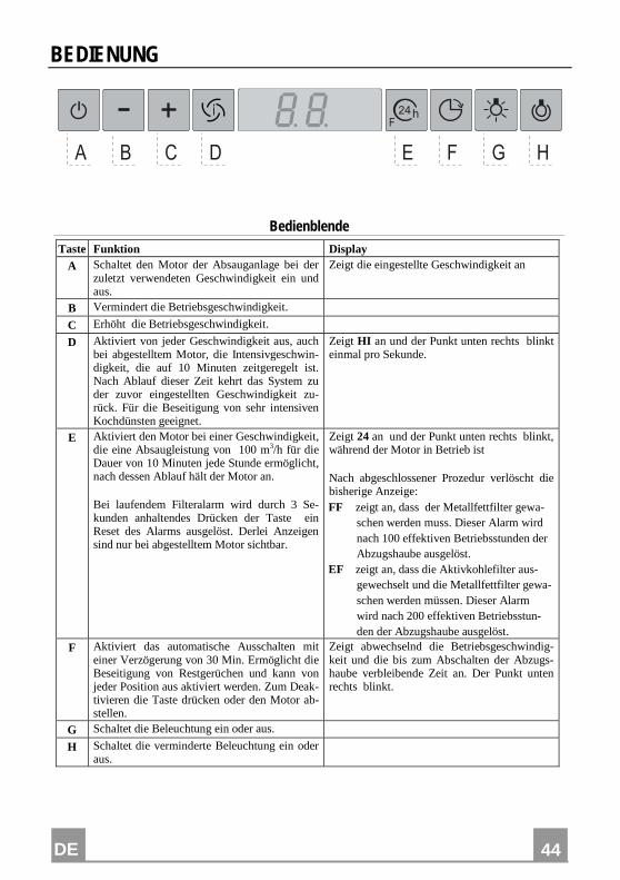
Bedienblende Taste Funktion Display
A Schaltet den Motor der Absauganlage bei der zuletzt verwendeten Geschwindigkeit ein und aus.
Zeigt die eingestellte Geschwindigkeit an
B Vermindert die Betriebsgeschwindigkeit.
C Erhöht die Betriebsgeschwindigkeit.
D Aktiviert von jeder Geschwindigkeit aus, auch bei abgestelltem Motor, die Intensivgeschwin-digkeit, die auf 10 Minuten zeitgeregelt ist. Nach Ablauf dieser Zeit kehrt das System zu der zuvor eingestellten Geschwindigkeit zu-rück. Für die Beseitigung von sehr intensiven Kochdünsten geeignet.
Zeigt HI an und der Punkt unten rechts blinkt einmal pro Sekunde.
E Aktiviert den Motor bei einer Geschwindigkeit, die eine Absaugleistung von 100 m3/h für die Dauer von 10 Minuten jede Stunde ermöglicht, nach dessen Ablauf hält der Motor an. Bei laufendem Filteralarm wird durch 3 Se-kunden anhaltendes Drücken der Taste ein Reset des Alarms ausgelöst. Derlei Anzeigen sind nur bei abgestelltem Motor sichtbar.
Zeigt 24 an und der Punkt unten rechts blinkt, während der Motor in Betrieb ist Nach abgeschlossener Prozedur verlöscht die bisherige Anzeige: FF zeigt an, dass der Metallfettfilter gewa-
schen werden muss. Dieser Alarm wird nach 100 effektiven Betriebsstunden der Abzugshaube ausgelöst.
EF zeigt an, dass die Aktivkohlefilter aus-gewechselt und die Metallfettfilter gewa-schen werden müssen. Dieser Alarm wird nach 200 effektiven Betriebsstun-den der Abzugshaube ausgelöst.
F Aktiviert das automatische Ausschalten mit einer Verzögerung von 30 Min. Ermöglicht die Beseitigung von Restgerüchen und kann von jeder Position aus aktiviert werden. Zum Deak-tivieren die Taste drücken oder den Motor ab-stellen.
Zeigt abwechselnd die Betriebsgeschwindig-keit und die bis zum Abschalten der Abzugs-haube verbleibende Zeit an. Der Punkt unten rechts blinkt.
G Schaltet die Beleuchtung ein oder aus.
H Schaltet die verminderte Beleuchtung ein oder aus.
DE
45
45
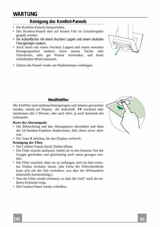
WARTUNG Reinigung des Komfort-Paneels
• Die Komfort-Paneels herausziehen. • Das Komfort-Paneel darf auf keinen Fall im Geschirrspüler
gespült werden. • Die Außenflächen mit einem feuchten Lappen und einem neutralen
Flüssigreiniger säubern. • Auch Innen mit einem feuchten Lappen und einem neutralen
Reinigungsmittel säubern; keine nassen Tücher oder Schwämme, oder gar Wasser verwenden, und keine schleifenden Mittel einsetzen.
• Zuletzt das Paneel wieder am Haubenkörper einhängen.
Metallfettfilter Die Fettfilter sind spülmaschinengeeignet und müssen gewaschen werden, sobald am Display die Aufschrift FF erscheint oder mindestens alle 2 Monate, oder auch öfter, je nach Intensität des Gebrauchs.
Reset des Alarmsignals • Die Beleuchtung und den Absaugmotor abschalten und dann
die 24-Stunden-Funktion deaktivieren, falls diese zuvor aktiv war.
• Die Taste E drücken, bis das Display verlöscht. Reinigung der Filter • Die Comfort Panels durch Ziehen öffnen. • Die Filter einzeln ausbauen, indem sie in den hinteren Teil der
Gruppe geschoben und gleichzeitig nach unten gezogen wer-den.
• Die Filter waschen, ohne sie zu verbiegen, und vor dem erneu-ten Einbau trocknen lassen. (die Farbe der Filteroberfläche kann sich mit der Zeit verändern, was aber die Wirksamkeit keinesfalls beeinträchtigt.)
• Nun die Filter wieder einbauen, so dass der Griff nach der äu-ßeren Sichtseite zeigt.
• Die Comfort Panel wieder schließen.
DE
46
46
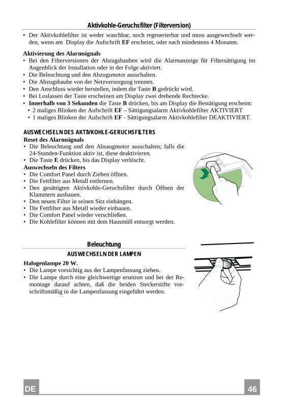
Aktivkohle-Geruchsfilter (Filterversion) • Der Aktivkohlefilter ist weder waschbar, noch regenerierbar und muss ausgewechselt wer-
den, wenn am Display die Aufschrift EF erscheint, oder nach mindestens 4 Monaten.
Aktivierung des Alarmsignals • Bei den Filterversionen der Abzugshauben wird die Alarmanzeige für Filtersättigung im
Augenblick der Installation oder in der Folge aktiviert. • Die Beleuchtung und den Abzugsmotor ausschalten. • Die Abzugshaube von der Netzversorgung trennen. • Den Anschluss wieder herstellen, indem die Taste B gedrückt wird. • Bei Loslassen der Taste erscheinen am Display zwei drehende Rechtecke. • Innerhalb von 3 Sekunden die Taste B drücken, bis am Display die Bestätigung erscheint:
• 2 maliges Blinken der Aufschrift EF – Sättigungsalarm Aktivkohlefilter AKTIVIERT • 1 maliges Blinken der Aufschrift EF - Sättigungsalarm Aktivkohlefilter DEAKTIVIERT.
AUSWECHSELN DES AKTIVKOHLE-GERUCHSFILTERS Reset des Alarmsignals • Die Beleuchtung und den Absaugmotor ausschalten; falls die
24-Stunden-Funktion aktiv ist, diese deaktivieren. • Die Taste E drücken, bis das Display verlöscht. Auswechseln des Filters • Die Comfort Panel durch Ziehen öffnen. • Die Fettfilter aus Metall entfernen. • Den gesättigten Aktivkohle-Geruchsfilter durch Öffnen der
Klammern ausbauen. • Den neuen Filter in seinen Sitz einhängen. • Die Fettfilter aus Metall wieder einbauen. • Die Comfort Panel wieder verschließen. • Die Kohlefilter können mit dem Hausmüll entsorgt werden.
Beleuchtung AUSWECHSELN DER LAMPEN
Halogenlampe 20 W. • Die Lampe vorsichtig aus der Lampenfassung ziehen. • Die Lampe durch eine gleichwertige ersetzen und bei der Re-
montage darauf achten, daß die beiden Steckerstifte vor-schriftsmäßig in die Lampenfassung eingeführt werden.
TR
47
47
TAVSIYELER VE ÖNERILER Bu kullanma talimatι birden fazla cihaz modeli için geçerlidir. Cihazιnιza uymayan bazι donanιm özellikleri tarif edilmiş olabilir.
MONTAJ • Yalnιş veya eksik montajdan doğan herhangi bir zararιn sorumluluğu üre-
ticiye ait değildir. • Davlumbaz ile pişirici cihazιn ocak kιsmι arasιndaki minimum güvenlik
mesafesi 500 mm.dir. • Besleme voltajιnιn, davlumbaz içerisine yerleştirilen bilgi etiketinde belirti-
lenle aynι olup olmadιğιnι kontrol edin. • Sιnιf I elektrikli aletleri için, güç kaynağιnιn yeterli topraklamayι sağlayιp
sağlamadιğιnι kontrol edin. Minimum 120 mm çapιnda bir boru yoluyla davlumbazι çιkιş bacasιna bağlayιn. Baca bağlantιsι mümkün oldu- ğunca kιsa olmalιdιr.
• Davlumbaz borusunu yanιcι duman taşιyan baca deliğine (buhar kazanι, şömine, vb.) bağlamayιn.
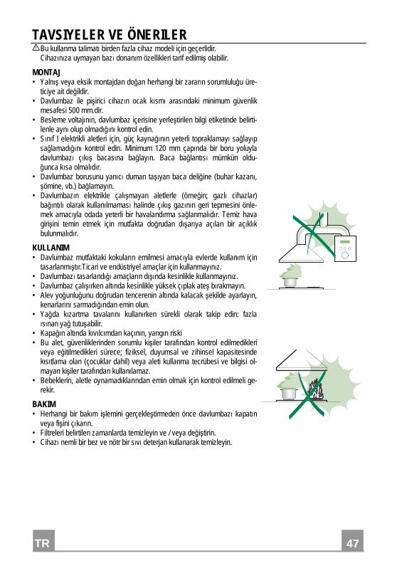
• Davlumbazιn elektrikle çalιşmayan aletlerle (örneğin; gazlι cihazlar) bağιntιlι olarak kullanιlmamasι halinde çιkιş gazιnιn geri tepmesini önle-mek amacιyla odada yeterli bir havalandιrma sağlanmalιdιr. Temiz hava girişini temin etmek için mutfakta doğrudan dιşarιya açιlan bir açιklιk bulunmalιdιr.
KULLANIM • Davlumbaz mutfaktaki kokularιn emilmesi amacιyla evlerde kullanιm için
tasarlanmιştιr.Ticari ve endüstriyel amaçlar için kullanmayιnιz. • Davlumbazι tasarlandιğι amaçlarιn dιşιnda kesinlikle kullanmayιnιz. • Davlumbaz çalιşιrken altιnda kesinlikle yüksek çιplak ateş bιrakmayιn. • Alev yoğunluğunu doğrudan tencerenin altιnda kalacak şekilde ayarlayιn,
kenarlarιnι sarmadιğιndan emin olun. • Yağda kιzartma tavalarιnι kullanιrken sürekli olarak takip edin: fazla
ιsιnan yağ tutuşabilir. • Kapağın altında kıvılcımdan kaçının, yangın riski • Bu alet, güvenliklerinden sorumlu kişiler tarafından kontrol edilmedikleri
veya eğitilmedikleri sürece; fiziksel, duyumsal ve zihinsel kapasitesinde kısıtlama olan (çocuklar dahil) veya aleti kullanma tecrübesi ve bilgisi ol-mayan kişiler tarafından kullanılamaz.
• Bebeklerin, aletle oynamadıklarından emin olmak için kontrol edilmeli ge-rekir.
BAKIM • Herhangi bir bakιm işlemini gerçekleştirmeden önce davlumbazι kapatιn
veya fişini çιkarιn. • Filtreleri belirtilen zamanlarda temizleyin ve / veya değiştirin. • Cihazι nemli bir bez ve nötr bir sιvι deterjan kullanarak temizleyin.
TR
48
48
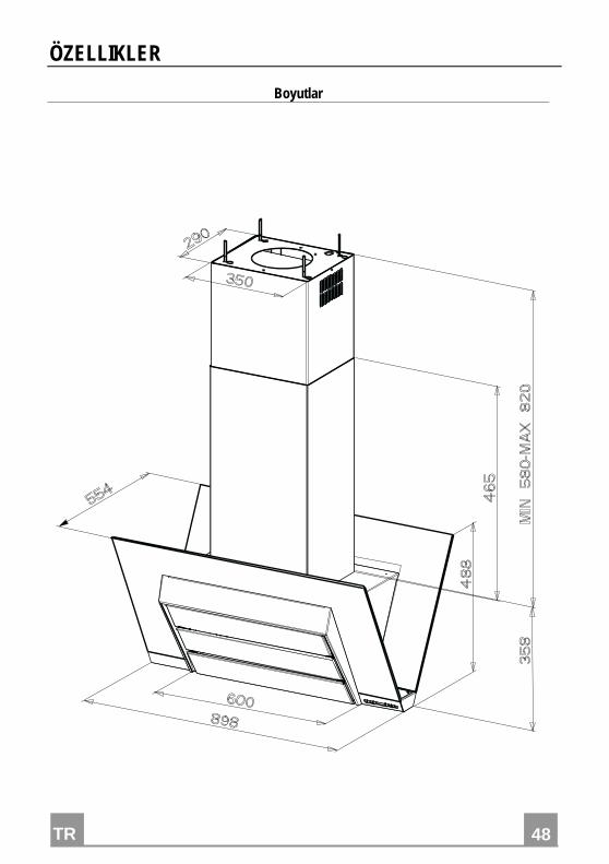
ÖZELLIKLER
Boyutlar
TR
49
49
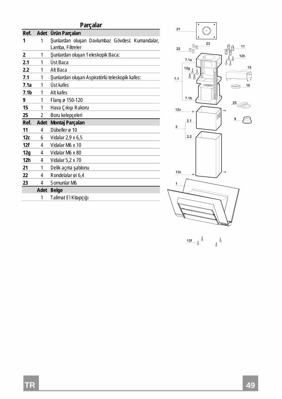
Parçalar Ref. Adet Ürün Parçaları 1 1 Şunlardan oluşan Davlumbaz Gövdesi: Kumandalar,
Lamba, Filtreler 2 1 Şunlardan oluşan Teleskopik Baca: 2.1 1 Üst Baca 2.2 1 Alt Baca 7.1 1 Şunlardan oluşan Aspiratörlü teleskopik kafes: 7.1a 1 Üst kafes 7.1b 1 Alt kafes 9 1 Flanş ø 150-120 15 1 Hava Çıkışı Rakoru 25 2 Boru kelepçeleri Ref. Adet Montaj Parçaları 11 4 Dübeller ø 10 12c 6 Vidalar 2,9 x 6,5 12f 4 Vidalar M6 x 10 12g 4 Vidalar M6 x 80 12h 4 Vidalar 5,2 x 70 21 1 Delik açma şablonu 22 4 Rondelalar øi 6,4 23 4 Somunlar M6 Adet Belge 1 Talimat El Kitapçığı
����
���
����
���
����
�
���
���
��
��
��
��
�
���
��
��
��
�
�
TR
50
50
MONTAJ
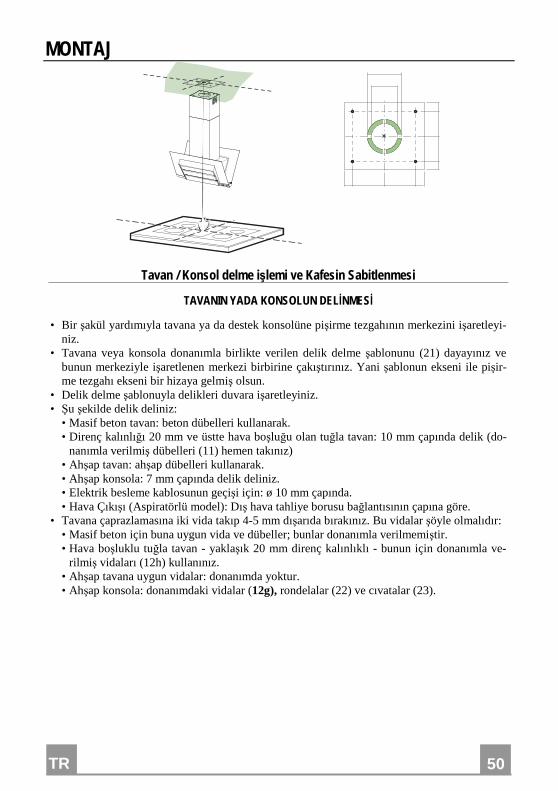
Tavan / Konsol delme işlemi ve Kafesin Sabitlenmesi
TAVANIN YADA KONSOLUN DELİNMESİ
• Bir şakül yardımıyla tavana ya da destek konsolüne pişirme tezgahının merkezini işaretleyi-niz.
• Tavana veya konsola donanımla birlikte verilen delik delme şablonunu (21) dayayınız ve bunun merkeziyle işaretlenen merkezi birbirine çakıştırınız. Yani şablonun ekseni ile pişir-me tezgahı ekseni bir hizaya gelmiş olsun.
• Delik delme şablonuyla delikleri duvara işaretleyiniz. • Şu şekilde delik deliniz: • Masif beton tavan: beton dübelleri kullanarak. • Direnç kalınlığı 20 mm ve üstte hava boşluğu olan tuğla tavan: 10 mm çapında delik (do-
nanımla verilmiş dübelleri (11) hemen takınız) • Ahşap tavan: ahşap dübelleri kullanarak. • Ahşap konsola: 7 mm çapında delik deliniz. • Elektrik besleme kablosunun geçişi için: ø 10 mm çapında. • Hava Çıkışı (Aspiratörlü model): Dış hava tahliye borusu bağlantısının çapına göre. • Tavana çaprazlamasına iki vida takıp 4-5 mm dışarıda bırakınız. Bu vidalar şöyle olmalıdır: • Masif beton için buna uygun vida ve dübeller; bunlar donanımla verilmemiştir. • Hava boşluklu tuğla tavan - yaklaşık 20 mm direnç kalınlıklı - bunun için donanımla ve-
rilmiş vidaları (12h) kullanınız. • Ahşap tavana uygun vidalar: donanımda yoktur. • Ahşap konsola: donanımdaki vidalar (12g), rondelalar (22) ve cıvatalar (23).
TR
51
51
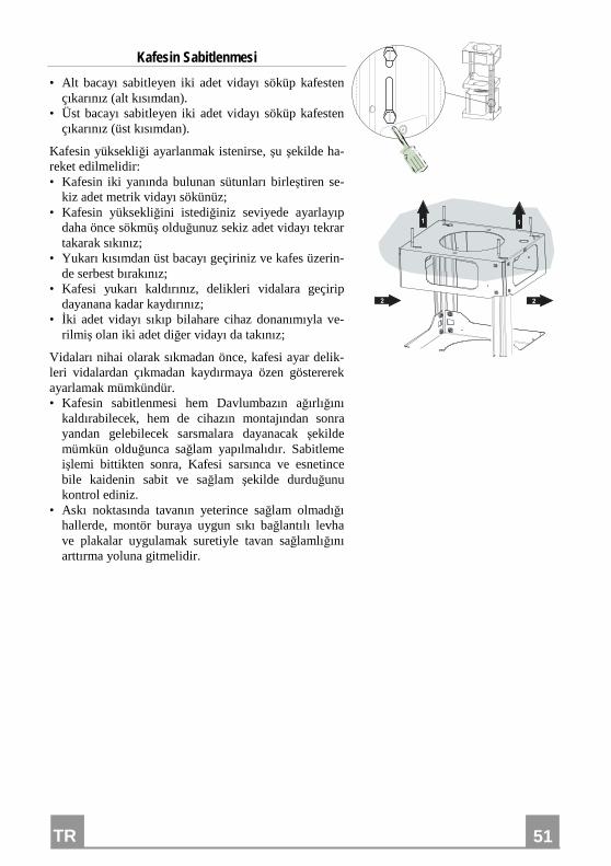
Kafesin Sabitlenmesi
• Alt bacayı sabitleyen iki adet vidayı söküp kafesten çıkarınız (alt kısımdan).
• Üst bacayı sabitleyen iki adet vidayı söküp kafesten çıkarınız (üst kısımdan).
Kafesin yüksekliği ayarlanmak istenirse, şu şekilde ha-reket edilmelidir: • Kafesin iki yanında bulunan sütunları birleştiren se-
kiz adet metrik vidayı sökünüz; • Kafesin yüksekliğini istediğiniz seviyede ayarlayıp
daha önce sökmüş olduğunuz sekiz adet vidayı tekrar takarak sıkınız;
• Yukarı kısımdan üst bacayı geçiriniz ve kafes üzerin-de serbest bırakınız;
• Kafesi yukarı kaldırınız, delikleri vidalara geçirip dayanana kadar kaydırınız;
• İki adet vidayı sıkıp bilahare cihaz donanımıyla ve-rilmiş olan iki adet diğer vidayı da takınız;
Vidaları nihai olarak sıkmadan önce, kafesi ayar delik-leri vidalardan çıkmadan kaydırmaya özen göstererek ayarlamak mümkündür. • Kafesin sabitlenmesi hem Davlumbazın ağırlığını
kaldırabilecek, hem de cihazın montajından sonra yandan gelebilecek sarsmalara dayanacak şekilde mümkün olduğunca sağlam yapılmalıdır. Sabitleme işlemi bittikten sonra, Kafesi sarsınca ve esnetince bile kaidenin sabit ve sağlam şekilde durduğunu kontrol ediniz.
• Askı noktasında tavanın yeterince sağlam olmadığı hallerde, montör buraya uygun sıkı bağlantılı levha ve plakalar uygulamak suretiyle tavan sağlamlığını arttırma yoluna gitmelidir.
� �
� �
TR
52
52
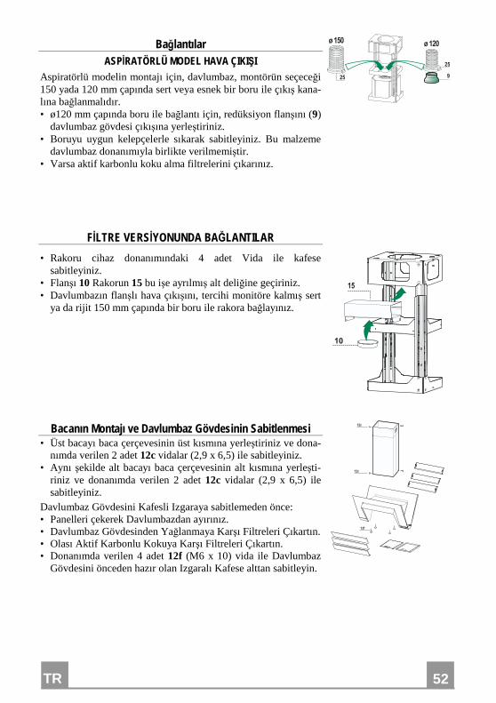
Bağlantılar ASPİRATÖRLÜ MODEL HAVA ÇIKIŞI
Aspiratörlü modelin montajı için, davlumbaz, montörün seçeceği 150 yada 120 mm çapında sert veya esnek bir boru ile çıkış kana-lına bağlanmalıdır. • ø120 mm çapında boru ile bağlantı için, redüksiyon flanşını (9)
davlumbaz gövdesi çıkışına yerleştiriniz. • Boruyu uygun kelepçelerle sıkarak sabitleyiniz. Bu malzeme
davlumbaz donanımıyla birlikte verilmemiştir. • Varsa aktif karbonlu koku alma filtrelerini çıkarınız.
�
����� �����
��
��
FİLTRE VERSİYONUNDA BAĞLANTILAR
• Rakoru cihaz donanımındaki 4 adet Vida ile kafese sabitleyiniz.
• Flanşı 10 Rakorun 15 bu işe ayrılmış alt deliğine geçiriniz. • Davlumbazın flanşlı hava çıkışını, tercihi monitöre kalmış sert
ya da rijit 150 mm çapında bir boru ile rakora bağlayınız.
��
�
Bacanın Montajı ve Davlumbaz Gövdesinin Sabitlenmesi • Üst bacayı baca çerçevesinin üst kısmına yerleştiriniz ve dona-
nımda verilen 2 adet 12c vidalar (2,9 x 6,5) ile sabitleyiniz. • Aynı şekilde alt bacayı baca çerçevesinin alt kısmına yerleşti-
riniz ve donanımda verilen 2 adet 12c vidalar (2,9 x 6,5) ile sabitleyiniz.
Davlumbaz Gövdesini Kafesli Izgaraya sabitlemeden önce: • Panelleri çekerek Davlumbazdan ayırınız. • Davlumbaz Gövdesinden Yağlanmaya Karşı Filtreleri Çıkartın. • Olası Aktif Karbonlu Kokuya Karşı Filtreleri Çıkartın. • Donanımda verilen 4 adet 12f (M6 x 10) vida ile Davlumbaz
Gövdesini önceden hazır olan Izgaralı Kafese alttan sabitleyin.
���
��
��
TR
53
53
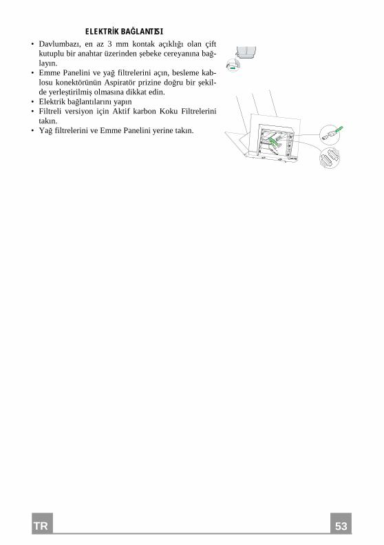
ELEKTRİK BAĞLANTISI • Davlumbazı, en az 3 mm kontak açıklığı olan çift
kutuplu bir anahtar üzerinden şebeke cereyanına bağ-layın.
• Emme Panelini ve yağ filtrelerini açın, besleme kab-losu konektörünün Aspiratör prizine doğru bir şekil-de yerleştirilmiş olmasına dikkat edin.
• Elektrik bağlantılarını yapın • Filtreli versiyon için Aktif karbon Koku Filtrelerini
takın. • Yağ filtrelerini ve Emme Panelini yerine takın.
TR
54
54
KULLANIM
� � � � � � � �
Kumanda Tablosu
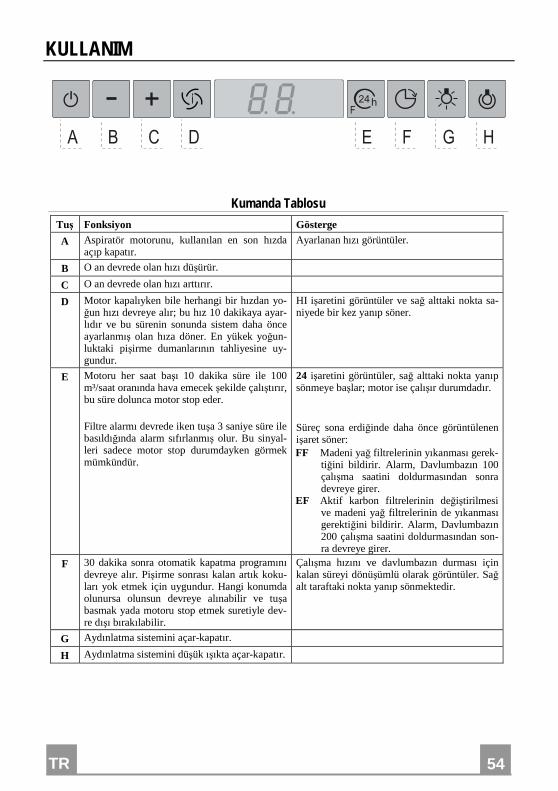
Tuş Fonksiyon Gösterge
A Aspiratör motorunu, kullanılan en son hızda açıp kapatır.
Ayarlanan hızı görüntüler.
B O an devrede olan hızı düşürür.
C O an devrede olan hızı arttırır.
D Motor kapalıyken bile herhangi bir hızdan yo-ğun hızı devreye alır; bu hız 10 dakikaya ayar-lıdır ve bu sürenin sonunda sistem daha önce ayarlanmış olan hıza döner. En yükek yoğun-luktaki pişirme dumanlarının tahliyesine uy-gundur.
HI işaretini görüntüler ve sağ alttaki nokta sa-niyede bir kez yanıp söner.
E Motoru her saat başı 10 dakika süre ile 100 m³/saat oranında hava emecek şekilde çalıştırır, bu süre dolunca motor stop eder. Filtre alarmı devrede iken tuşa 3 saniye süre ile basıldığında alarm sıfırlanmış olur. Bu sinyal-leri sadece motor stop durumdayken görmek mümkündür.
24 işaretini görüntüler, sağ alttaki nokta yanıp sönmeye başlar; motor ise çalışır durumdadır. Süreç sona erdiğinde daha önce görüntülenen işaret söner: FF Madeni yağ filtrelerinin yıkanması gerek-
tiğini bildirir. Alarm, Davlumbazın 100 çalışma saatini doldurmasından sonra devreye girer.
EF Aktif karbon filtrelerinin değiştirilmesi ve madeni yağ filtrelerinin de yıkanması gerektiğini bildirir. Alarm, Davlumbazın 200 çalışma saatini doldurmasından son-ra devreye girer.
F 30 dakika sonra otomatik kapatma programını devreye alır. Pişirme sonrası kalan artık koku-ları yok etmek için uygundur. Hangi konumda olunursa olunsun devreye alınabilir ve tuşa basmak yada motoru stop etmek suretiyle dev-re dışı bırakılabilir.
Çalışma hızını ve davlumbazın durması için kalan süreyi dönüşümlü olarak görüntüler. Sağ alt taraftaki nokta yanıp sönmektedir.
G Aydınlatma sistemini açar-kapatır.
H Aydınlatma sistemini düşük ışıkta açar-kapatır.
TR
55
55
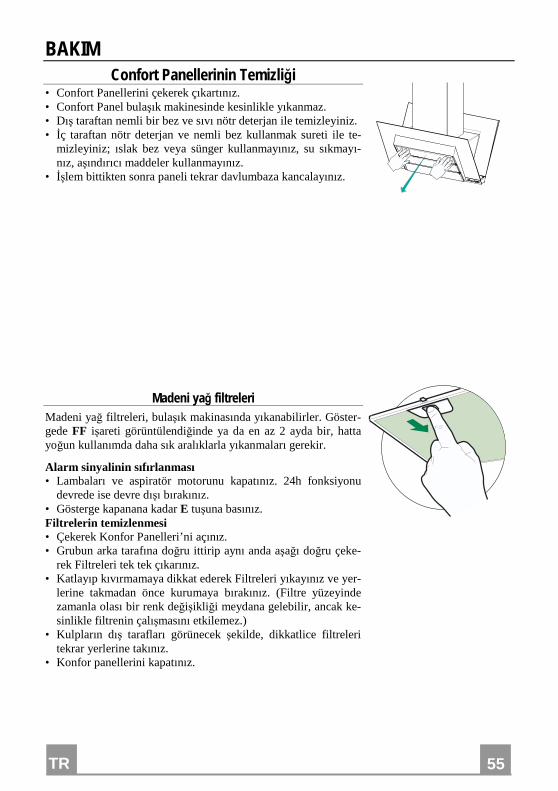
BAKIM Confort Panellerinin Temizliği
• Confort Panellerini çekerek çıkartınız. • Confort Panel bulaşık makinesinde kesinlikle yıkanmaz. • Dış taraftan nemli bir bez ve sıvı nötr deterjan ile temizleyiniz. • İç taraftan nötr deterjan ve nemli bez kullanmak sureti ile te-
mizleyiniz; ıslak bez veya sünger kullanmayınız, su sıkmayı-nız, aşındırıcı maddeler kullanmayınız.
• İşlem bittikten sonra paneli tekrar davlumbaza kancalayınız.
Madeni yağ filtreleri Madeni yağ filtreleri, bulaşık makinasında yıkanabilirler. Göster-gede FF işareti görüntülendiğinde ya da en az 2 ayda bir, hatta yoğun kullanımda daha sık aralıklarla yıkanmaları gerekir.
Alarm sinyalinin sıfırlanması • Lambaları ve aspiratör motorunu kapatınız. 24h fonksiyonu
devrede ise devre dışı bırakınız. • Gösterge kapanana kadar E tuşuna basınız. Filtrelerin temizlenmesi • Çekerek Konfor Panelleri’ni açınız. • Grubun arka tarafına doğru ittirip aynı anda aşağı doğru çeke-
rek Filtreleri tek tek çıkarınız. • Katlayıp kıvırmamaya dikkat ederek Filtreleri yıkayınız ve yer-
lerine takmadan önce kurumaya bırakınız. (Filtre yüzeyinde zamanla olası bir renk değişikliği meydana gelebilir, ancak ke-sinlikle filtrenin çalışmasını etkilemez.)
• Kulpların dış tarafları görünecek şekilde, dikkatlice filtreleri tekrar yerlerine takınız.
• Konfor panellerini kapatınız.
TR
56
56
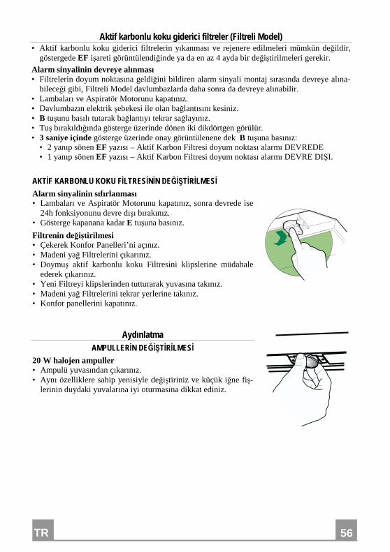
Aktif karbonlu koku giderici filtreler (Filtreli Model) • Aktif karbonlu koku giderici filtrelerin yıkanması ve rejenere edilmeleri mümkün değildir,
göstergede EF işareti görüntülendiğinde ya da en az 4 ayda bir değiştirilmeleri gerekir.
Alarm sinyalinin devreye alınması • Filtrelerin doyum noktasına geldiğini bildiren alarm sinyali montaj sırasında devreye alına-
bileceği gibi, Filtreli Model davlumbazlarda daha sonra da devreye alınabilir. • Lambaları ve Aspiratör Motorunu kapatınız. • Davlumbazın elektrik şebekesi ile olan bağlantısını kesiniz. • B tuşunu basılı tutarak bağlantıyı tekrar sağlayınız. • Tuş bırakıldığında gösterge üzerinde dönen iki dikdörtgen görülür. • 3 saniye içinde gösterge üzerinde onay görüntülenene dek B tuşuna basınız:
• 2 yanıp sönen EF yazısı – Aktif Karbon Filtresi doyum noktası alarmı DEVREDE • 1 yanıp sönen EF yazısı – Aktif Karbon Filtresi doyum noktası alarmı DEVRE DIŞI.
AKTİF KARBONLU KOKU FİLTRESİNİN DEĞİŞTİRİLMESİ Alarm sinyalinin sıfırlanması • Lambaları ve Aspiratör Motorunu kapatınız, sonra devrede ise
24h fonksiyonunu devre dışı bırakınız. • Gösterge kapanana kadar E tuşuna basınız.
Filtrenin değiştirilmesi • Çekerek Konfor Panelleri’ni açınız. • Madeni yağ Filtrelerini çıkarınız. • Doymuş aktif karbonlu koku Filtresini klipslerine müdahale
ederek çıkarınız. • Yeni Filtreyi klipslerinden tutturarak yuvasına takınız. • Madeni yağ Filtrelerini tekrar yerlerine takınız. • Konfor panellerini kapatınız.
Aydınlatma AMPULLERİN DEĞİŞTİRİLMESİ
20 W halojen ampuller • Ampulü yuvasından çıkarınız. • Aynı özelliklere sahip yenisiyle değiştiriniz ve küçük iğne fiş-
lerinin duydaki yuvalarına iyi oturmasına dikkat ediniz.


436004089_ver2
The symbol on the product or on its packaging indicates that this product may not be treated as household waste. Instead it shall be handed over to the applicable collection point for the recycling of electrical and electronic equipment. By ensuring this product is
disposed of correctly, you will help prevent potential negative consequences for the environment and human health, which could oth-erwise be caused by inappropriate waste handling of this product. For more detailed information about recycling of this product, please contact your local city office, your household waste disposal service or the shop where you purchased the product.
Il simbolo sul prodotto o sulla confezione indica che il prodotto non deve essere considerato come un normale rifiuto domestico, ma deve essere portato nel punto di raccolta appropriato per il riciclaggio di apparecchiature elettriche ed elettroniche. Provvedendo a smaltire questo prodotto in modo appropriato, si contribuisce a evitare potenziali conseguenze negative per l’ambiente e per la salute,
che potrebbero derivare da uno smaltimento inadeguato del prodotto. Per informazioni più dettagliate sul riciclaggio di questo prodotto, contattare l’ufficio comunale, il servizio locale di smaltimento rifiuti o il negozio in cui è stato acquistato il prodotto.
Le symbole sur le produit ou son emballage indique que ce produit ne peut être traité comme déchet ménager. Il doit plutôt être
remis au point de ramassage concerné, se chargeant du recyclage du matériel électrique et électronique. En vous assurant que ce produit est éliminé correctement, vous favorisez la prévention des conséquences négatives pour l’environnement et la santé humaine qui, sinon, seraient le résultat d’un traitement inapproprié des déchets de ce produit. Pour obtenir plus de détails sur le recyclage de ce
produit, veuillez prendre contact avec le bureau municipal de votre région, votre service d’élimination des déchets ménagers ou le magasin où vous avez acheté le produit.
Das Symbol auf dem Produkt oder seiner Verpackung weist darauf hin, dass dieses Produkt nicht als normaler Haushaltsabfall zu behandeln ist, sondern an einem Sammelpunkt für das Recycling von elektrischen und elektronischen Geräten abgegeben werden muss. Durch Ihren Beitrag zum korrekten Entsorgen dieses Produkts schützen Sie die Umwelt und die Gesundheit Ihrer Mitmenschen.
Umwelt und Gesundheit werden durch falsches Entsorgen gefährdet. Weitere Informationen über das Recycling dieses Produkts erhalten Sie von Ihrem Rathaus, Ihrer Müllabfuhr oder dem Geschäft, in dem Sie das Produkt gekauft haben.
Ürün veya paketi üzerindeki sembolü, bu ürünün normal bir evsel atık olarak görülmemesi ve bu tip elektrikli veya elektronik
cihazların atıldığı dönüşümlü toplama noktalarına terkedilmesi gerektiğine işaret eder. Bu ürünü gerektiği gibi elimine etme kurallarına uyarsanız çevre ve insan sağlığı üzerindeki olumsuz etkilerini bertaraf etmeye katkı sağlamış olursunuz. Bu ürünün geri dönüşüm koşulları hakkında daha ayrıntılı bilgi için hudutları içinde bulunduğunuz belediyenin ilgili diaresine, atık yoketme servisine veya ürünün
satıcısına danışınız.
Franke S.p.a. Via Pignolini,2 37019 Peschiera del Garda (VR) www.franke.it