JES-301 JES-301V€¦ · JES-301 anpassungsfähig für verschiedenste Applika - tionen. 1.3....
34
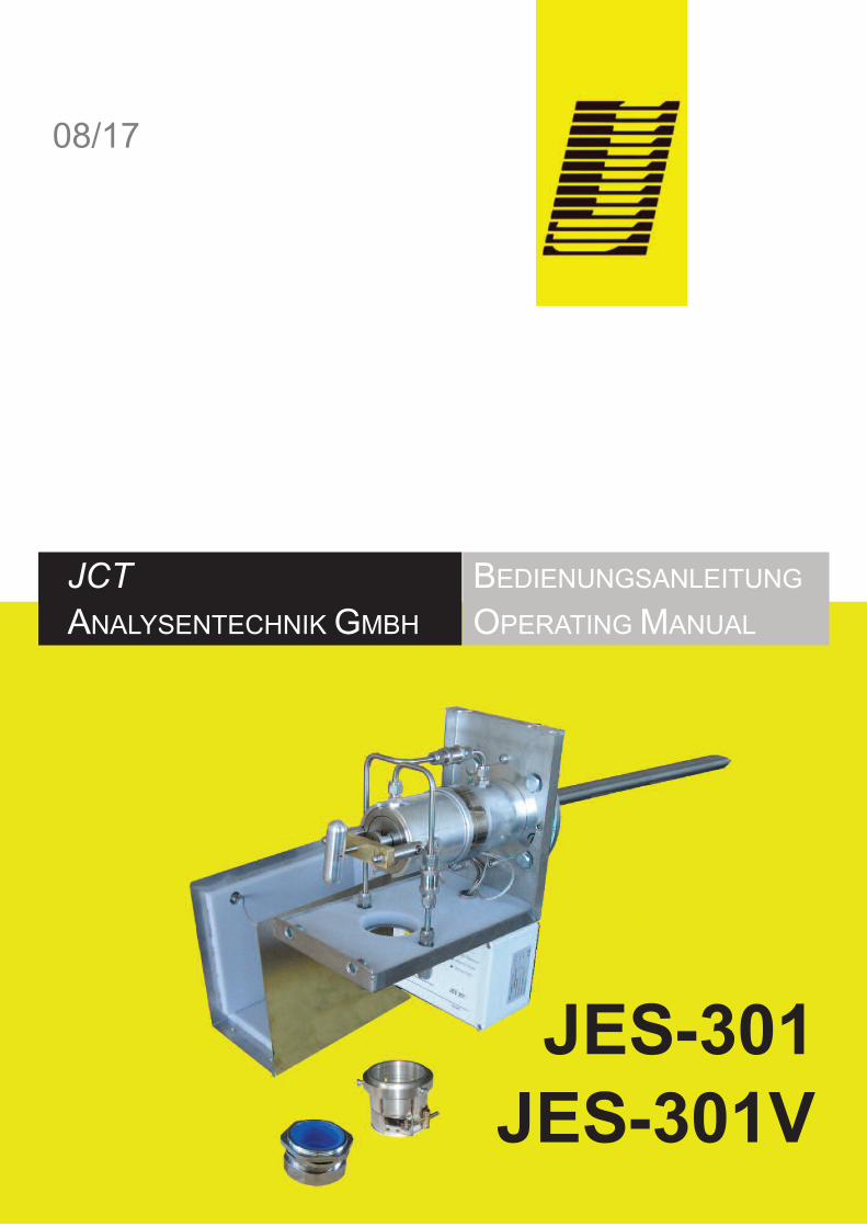
JCT ANALYSENTEcHNIK GMBH BEDIENUNGSANLEITUNG OPERATING MANUAL 08/17 JES-301 JES-301V
Transcript of JES-301 JES-301V€¦ · JES-301 anpassungsfähig für verschiedenste Applika - tionen. 1.3....
JCTANALySENTEchNIk GMBh
BEDIENUNGSANLEITUNG
OPERATING MANUAL
08/17
JES-301JES-301V

Inhalt Table of Content
© 2017 JcT Analysentechnik GmbhReproduktion im Ganzen oder auszugsweise ohne vor-herige schriftliche Genehmigung verboten.Alle verwendeten Markenzeichen sind Eigentum der ent-sprechenden Rechteinhaber.JcT bietet diese Betriebsanleitung "wie vorliegend" ohnejede Garantie in irgendeiner Art, weder ausdrücklichnoch stillschweigend, einschließlich Garantien oder Be-dingungen der Marktgängigkeit oder Eignung für einenbestimmten Zweck.Technische Änderungen vorbehalten.
© 2017 by JcT Analysentechnik GmbhReproduction in whole or in part in any form or mediumwithout written permission is prohibitedAll trademarks not explicitly mentioned are property oftheir legal owners.JcT provides this operating manual "as is" without anywarranty of any kind, either express or implied, includingwarranties or conditions of merchantability or fitness fora particular purpose.
Subject to technical modifications without notice.
Manual JES-301/JES-301V
BA_DE_JES301_v2.1 ––––––––––––––– [ 2 / 34 ] –––––––––––––––––
1. Introduction 31.1. Mounting 31.2. Versatile 31.3. Service and security 31.4. General safety information 3
2. Description 42.1. Optionen 72.2. Upgrade Options 7
3. Technical data 94. Installation, unpacking 125. Installation instructions 12
5.1. Mounting 125.2. Electrical connections 16
6. Start up 177. Maintenance and service 18
7.1. Replacement of filter element 188. Connection of a junction box 19
8.1. Electrical connection (junction box) 198.2. Connection of spring type terminal 19
9. Temperature controller abstract 2010. Fault diagnostic check list 2311. Dimensions 2412. Order codes 25
12.1. Accessories 2612.2. Spare parts 2912.3. Consumables 3012.4. Upgrade options 30
13. Information about upgrade options 3213.1. Pneumatic actuator process shut-off valve 3213.2. Electric actuator for process shut-off valve 3213.3. Air accumulator 3313.4. High temperature version 3313.5. Temperature display 33
1. Einleitung 31.1. Montage 31.2. Modular 31.3. Service und Sicherheit 31.4. Allgemeine Sicherheitsinformation 3
2. Beschreibung 42.1. Optionen 72.2. Erweiterungsoptionen 7
3. Technische Daten 94. Installation, Sichtkontrolle 125. Installationsvorschriften 12
5.1. Montage 125.2. Elektrischer Anschluss 16
6. Inbetriebnahme 177. Wartung und Service 18
7.1. Ersetzen des Filterelementes 188. Anschluss einer Klemmenbox 19
8.1. Elektrischer Anschluss (Klemmenbox) 198.2. Anschluss von Federzugklemmen 19
9. Temperaturregler Allgemein 2010. Fehlerdiagnose Checkliste 2311. Abmessungen 2412. Bestellcodes 25
12.1. Zubehör 2612.2. Ersatzteile 2912.3. Verschleißteile 3012.4. Erweiterungsoptionen 30
13. Informationen zu Erweiterungsoptionen 3213.1. Pneumatischer Aktuator für Prozessabsperrventil 3213.2. Elektrischer Aktuator für Prozessabsperrventil 3213.3. Puffertank 3313.4. Hochtemperaturausführung 3313.5. Digitale Temperaturanzeige 33
Manual JES-301/JES-301V
BA_DE_JES301_v2.1 ––––––––––––––– [ 3 / 34 ] –––––––––––––––––
Einleitung1.Die beheizte Gasentnahmesonde JES-301 dient zurkontinuierlichen Entnahme von staub- und aerosol-hal-tigen Gasen bei extraktiven Analysensystemen. Wasser-dampf und hohe korrosive Gasfeuchte müssen überdem Taupunkt gehalten werden, damit keine Verände-rung des Gases vor den Analysengeräten oder der Pro-benaufbereitung stattfinden kann.Die Gasentnahmesonde JES-301 ist in verschiedenenVersionen lieferbar. Dadurch können unterschiedlicheAnforderungen erfüllt werden.Die JES-301 ist mit einem großflächigen, austauschba-ren beheizten keramik-Filterelement ausgestattet. DasFilterelement ist in einem elektrisch beheizten Edelstahl-gehäuse montiert und zusätzlich in einem thermisch iso-lierten Wetterschutzgehäuse untergebracht. DieJES-301V sind zusätzlich mit einem Prozessabsperr-ventil ausgestattet. Die Temperaturregelung erfolgtdurch eine wartungsfreie vollelektronische Regelung mitAlarmmeldung bei Untertemperatur. Die beheizte Mess-gasleitung der Serie Jh wird direkt am Gehäuse derSonde über eine verschiebbare PG42 Verschraubungmontiert. Für die Montage für anderer heizleitungstypensteht eine Montageschelle zur Verfügung. Für eine kor-rekte und optimale Auswahl der verschiedenen Entnah-merohre und Materialien steht Ihnen unser geschultesPersonal gerne zur Seite.
Montage1.1.Die Gasentnahmesonde besteht aus dem beheiztem Fil-terkopf, Temperaturregler, Montageflansch und Monta-gematerial. Sie kann horizontal oder vertikal montiertwerden. Die Sonde wird direkt an einem Standard-Pro-zessflansch montiert. Wenn die Montage horizontal er-folgt, sollte die JES-301 zumindest zwischen 5° und 15°aus der horizontalen fallend eingebaut werden, damitanfallendes kondensat zurück in den Prozess abgeleitetwerden kann.
Modular1.2.Unterschiedliche Entnahmerohrmaterialien, elektrischbeheizte Entnahmerohre und große Vorfilter machen dieJES-301 anpassungsfähig für verschiedenste Applika-tionen.
Service und Sicherheit1.3.Ein Statuskontakt signalisiert Störung und Untertempe-ratur, eine Übertemperaturbegrenzung schützt vor Über-hitzung. Der Filterwechsel kann ohne Werkzeug undohne Demontage der beheizten Messgasleitung durch-geführt werden.
Allgemeine Sicherheitsinformation1.4.Die Gasentnahmesonden sind hochentwickelte Geräte,die nur von qualifiziertem Personal bedient werden dür-fen. Es ist notwendig, dass dieses handbuch von jenen,die diese Ausrüstung installieren, benutzen bzw. warten,gelesen und verstanden wurde.
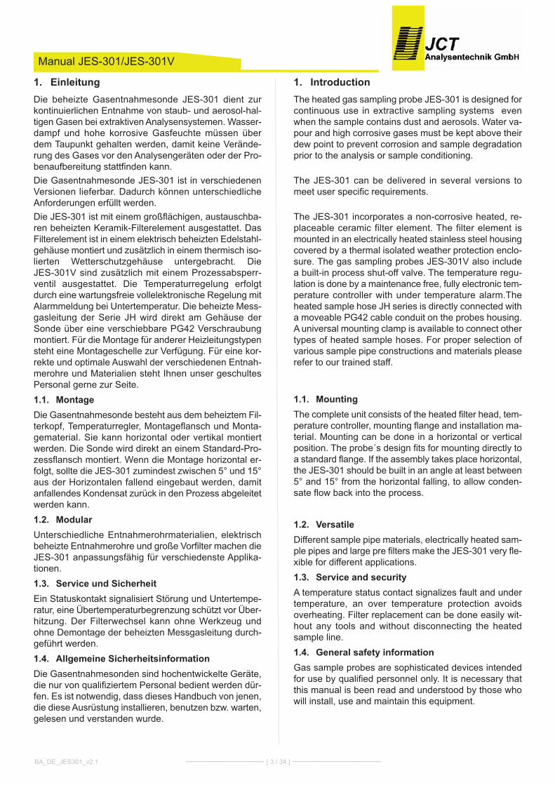
Introduction1.The heated gas sampling probe JES-301 is designed forcontinuous use in extractive sampling systems evenwhen the sample contains dust and aerosols. Water va-pour and high corrosive gases must be kept above theirdew point to prevent corrosion and sample degradationprior to the analysis or sample conditioning.
The JES-301 can be delivered in several versions tomeet user specific requirements.
The JES-301 incorporates a non-corrosive heated, re-placeable ceramic filter element. The filter element ismounted in an electrically heated stainless steel housingcovered by a thermal isolated weather protection enclo-sure. The gas sampling probes JES-301V also includea built-in process shut-off valve. The temperature regu-lation is done by a maintenance free, fully electronic tem-perature controller with under temperature alarm.Theheated sample hose Jh series is directly connected witha moveable PG42 cable conduit on the probes housing.A universal mounting clamp is available to connect othertypes of heated sample hoses. For proper selection ofvarious sample pipe constructions and materials pleaserefer to our trained staff.
Mounting1.1.The complete unit consists of the heated filter head, tem-perature controller, mounting flange and installation ma-terial. Mounting can be done in a horizontal or verticalposition. The probe´s design fits for mounting directly toa standard flange. If the assembly takes place horizontal,the JES-301 should be built in an angle at least between5° and 15° from the horizontal falling, to allow conden-sate flow back into the process.
Versatile1.2.Different sample pipe materials, electrically heated sam-ple pipes and large pre filters make the JES-301 very fle-xible for different applications.
Service and security1.3.A temperature status contact signalizes fault and undertemperature, an over temperature protection avoidsoverheating. Filter replacement can be done easily wit-hout any tools and without disconnecting the heatedsample line.
General safety information1.4.Gas sample probes are sophisticated devices intendedfor use by qualified personnel only. It is necessary thatthis manual is been read and understood by those whowill install, use and maintain this equipment.
CAUTIONThe sample probe JES-301 is not suitable for use in ha-zardous areas.
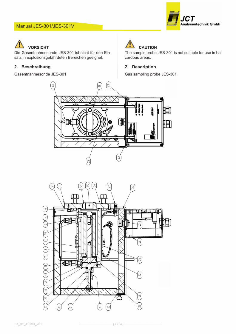
Description2.Gas sampling probe JES-301
VORSICHTDie Gasentnahmesonde JES-301 ist nicht für den Ein-satz in explosionsgefährdeten Bereichen geeignet.
Beschreibung2.Gasentnahmesonde JES-301
Manual JES-301/JES-301V
BA_DE_JES301_v2.1 ––––––––––––––– [ 4 / 34 ] –––––––––––––––––
,
,,
,
,
,,
,
,,
��
��
����
��
��
�,,
,,
,,
,,
,,
,,
,,
,,
,,
,,
,,
,,
,,
,,
,,
,,
,,
,,
,,
,,
,
,
,
,,
,,
,,
,,,
,,,,,,,��������,
��������
*��������1�
*��������1�
*���
�*���
�
�� -�� �
��
%�
����
����
�� �� �� �� ����
-���
��--
-�
�� ��
��
�-
-�
-%
-��
-�
-��
�-
Manual JES-301/JES-301V
BA_DE_JES301_v2.1 ––––––––––––––– [ 5 / 34 ] –––––––––––––––––
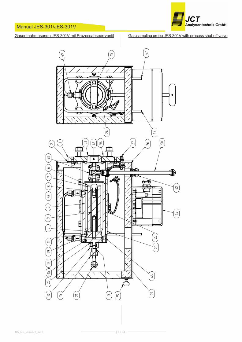
Gas sampling probe JES-301V with process shut-off valveGasentnahmesonde JES-301V mit Prozessabsperrventil
)
))
)
)
))
)
))
��
��
����
��
��
�))
))
))
)))
))
))
)))
))
))
)))
))
)))
)))
))
))
))
))
))
)
)
))
) )
)))))))*��A��*�)
��������
))))
))
����
�
��
�
���
����
�� �� ��
����
��
�
�
�
�
���� � ��
�
�� ��
���
�
���
����
�

Manual JES-301/JES-301V
BA_DE_JES301_v2.1 ––––––––––––––– [ 6 / 34 ] –––––––––––––––––
1 Flansch
2 Gehäusedichtung
5 Mantel
6 Filterelementverschraubung
7 Filterelementdichtung
8 Filterelement
9 Filterhalter Trägerelement
10 Filterhalter Dichtkolben
11 O-Ring B
12 O-Ring A
13 Abziehbolzen
15 Schwenkarm
17 Abziehvorrichtung
21 T - Griff
22 Alu Mantel
23 Ringheizkörper
24 Temperaturfühler PT 100
25 Wärme Isolation
26 Gehäuse
27 Erdungsanschluss
35 Gehäuseverschluss
42 kabelverschraubung
43 Absperrkugelhahn
44 Temperaturregler
45 Messgas Eingang
46 Messgas Ausgang
47 Anschluss Rückspülung (optional)
48 kalibriergas Anschluss (optional)
49 Rückschlagventil
50 T-Griff für Absperrkugelhahn
53 Dichtung für Entnahmerohr
54 Flanschdichtung
1 Flange
2 housing gasket
5 cylinder
6 Filter element screw
7 Filter element gasket
8 Filter
9 Filter retainer
10 Filter tighting piston
11 O-ring B
12 O-ring A
13 Bolt
15 Pivoting frame
17 Extractor
21 T - handle
22 Aluminium cover
23 Ring heater element
24 Temperature sensor PT 100
25 Thermal isolation
26 housing
27 Ground connection pin
35 housing lock
42 Screwed cable gland
43 Process shut-off ball valve
44 Temperature controller
45 Sample gas inlet
46 Sample gas outlet
47 Back purge port (option)
48 calibration gas port (option)
49 Non return valve
50 T-handle for process shut-off ball valve
53 Gasket for sample tube
54 Flange gasket
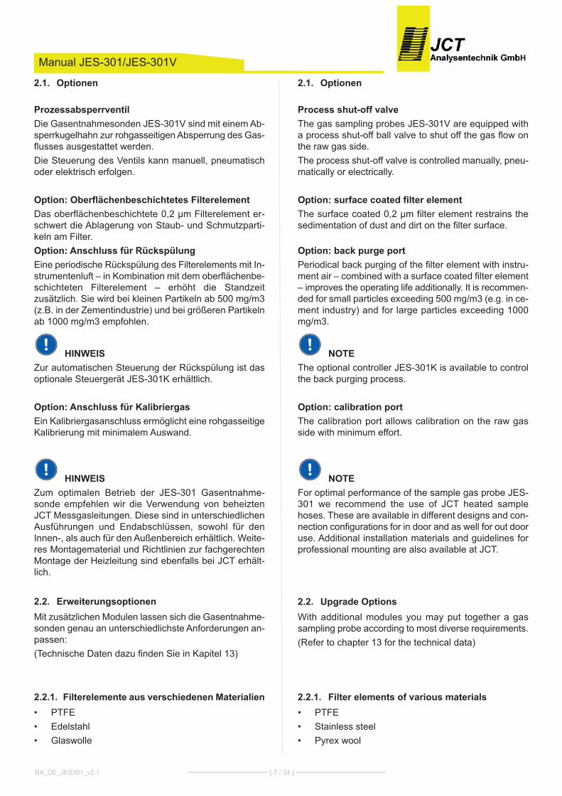
Optionen2.1.
Process shut-off valveThe gas sampling probes JES-301V are equipped witha process shut-off ball valve to shut off the gas flow onthe raw gas side.The process shut-off valve is controlled manually, pneu-matically or electrically.
Option: surface coated filter elementThe surface coated 0,2 µm filter element restrains thesedimentation of dust and dirt on the filter surface.
Option: back purge portPeriodical back purging of the filter element with instru-ment air – combined with a surface coated filter element– improves the operating life additionally. It is recommen-ded for small particles exceeding 500 mg/m3 (e.g. in ce-ment industry) and for large particles exceeding 1000mg/m3.
NOTEThe optional controller JES-301k is available to controlthe back purging process.
Option: calibration portThe calibration port allows calibration on the raw gasside with minimum effort.
NOTEFor optimal performance of the sample gas probe JES-301 we recommend the use of JcT heated samplehoses. These are available in different designs and con-nection configurations for in door and as well for out dooruse. Additional installation materials and guidelines forprofessional mounting are also available at JcT.
Upgrade Options2.2.With additional modules you may put together a gassampling probe according to most diverse requirements.(Refer to chapter 13 for the technical data)
Filter elements of various materials2.2.1.PTFE•Stainless steel•Pyrex wool•
Manual JES-301/JES-301V
Optionen2.1.
ProzessabsperrventilDie Gasentnahmesonden JES-301V sind mit einem Ab-sperrkugelhahn zur rohgasseitigen Absperrung des Gas-flusses ausgestattet werden.Die Steuerung des Ventils kann manuell, pneumatischoder elektrisch erfolgen.
Option: Oberflächenbeschichtetes FilterelementDas oberflächenbeschichtete 0,2 µm Filterelement er-schwert die Ablagerung von Staub- und Schmutzparti-keln am Filter.Option: Anschluss für RückspülungEine periodische Rückspülung des Filterelements mit In-strumentenluft – in kombination mit dem oberflächenbe-schichteten Filterelement – erhöht die Standzeitzusätzlich. Sie wird bei kleinen Partikeln ab 500 mg/m3(z.B. in der Zementindustrie) und bei größeren Partikelnab 1000 mg/m3 empfohlen.
HINWEISZur automatischen Steuerung der Rückspülung ist dasoptionale Steuergerät JES-301k erhältlich.
Option: Anschluss für KalibriergasEin kalibriergasanschluss ermöglicht eine rohgasseitigekalibrierung mit minimalem Auswand.
HINWEISZum optimalen Betrieb der JES-301 Gasentnahme-sonde empfehlen wir die Verwendung von beheiztenJcT Messgasleitungen. Diese sind in unterschiedlichenAusführungen und Endabschlüssen, sowohl für denInnen-, als auch für den Außenbereich erhältlich. Weite-res Montagematerial und Richtlinien zur fachgerechtenMontage der heizleitung sind ebenfalls bei JcT erhält-lich.
Erweiterungsoptionen2.2.Mit zusätzlichen Modulen lassen sich die Gasentnahme-sonden genau an unterschiedlichste Anforderungen an-passen:(Technische Daten dazu finden Sie in kapitel 13)
Filterelemente aus verschiedenen Materialien2.2.1.PTFE•Edelstahl•Glaswolle•
BA_DE_JES301_v2.1 ––––––––––––––– [ 7 / 34 ] –––––––––––––––––

Back purge control valves and reduction2.2.2.valves
Directly on the probe-mounted backpurge control valveswith a large passage opening allow efficient backpurgeresults with compact design. These valves are availablein several coil voltages.To reduce the pressure shocks occurring during the backpurge of the sample gas gas output, the pressure re-duction valve JBPRV integrated in the connection fittingis used.
Actuators and pilot valves for process shut-2.2.3.off valves
Versions of the sampling probes with process-side shut-off are equipped with a full-bore size ball valve and canbe operated manual, pneumatic or electrical. A pilotvalve on the actuator can also be installed for pneumaticcontrol.For managing the entire backprurge process aback purge controller is also available.
Air accumulator2.2.4.heated or unheated air accumulators with a volume of 2or 5 liters can be used for back purging.
High temperature versions2.2.5.This model of gas sampling probecan be heated up totemperatures up to 315°c.
Digital display for temperature controller2.2.6.In addition to the status indicator LEDs the temperatureand error messages are shown on a display.
Manual JES-301/JES-301V
Rückspül-Steuerventile und Reduktionsven-2.2.2.tile
Direkt am Sondengehäuse angebaute Rückspül-Steu-erventile mit großer Durchgangsöffnung ermöglichen ef-fiziente Rückspülergebnisse bei kompakter Bauweise.Diese Ventile stehen in mehreren Spulenspannungenzur Verfügung.Zur Reduzierung der bei der Rückspülung auftretenderDruckstößen am Messgasausgang kommt das in derAnschlussverschraubung integrierte DruckminderventilJBPRV zum Einsatz.
Steuerungen und Pilotventile für Prozessab-2.2.3.sperrventil
Ausführungen der Gasentnahmmesonden mit Prozess-seitiger Absperrung sind mit einem Volldurchgangs ku-gelhahn ausgestattet und können in manuellerpneumatischer oder elektrischer Betätigung betriebenwerden. Für die pneumatische Ansteuerung kann zu-sätzlich ein Pilotventil am Aktuator angebracht werden.Für den gesamten Steuerungsablauf steht eine Rück-spülsteuerung zur Verfügung.
Puffertank2.2.4.Zur Versorgung der Rückspülung stehen beheizte undunbeheizte Puffertanks mit 2 oder 5 Liter Volumen zurVerfügung.
Hochtemperaturausführungen2.2.5.In dieser Ausführung kann die Gasentnahmesonde aufbis zu 315°c beheizt werden.
Digitale Anzeige für Temperaturregler2.2.6.Zusätzlich zu den LEDs Statusanzeigen werden Tempe-ratur und Fehlerzustände auf einem Display angezeigt.
BA_DE_JES301_v2.1 ––––––––––––––– [ 8 / 34 ] –––––––––––––––––
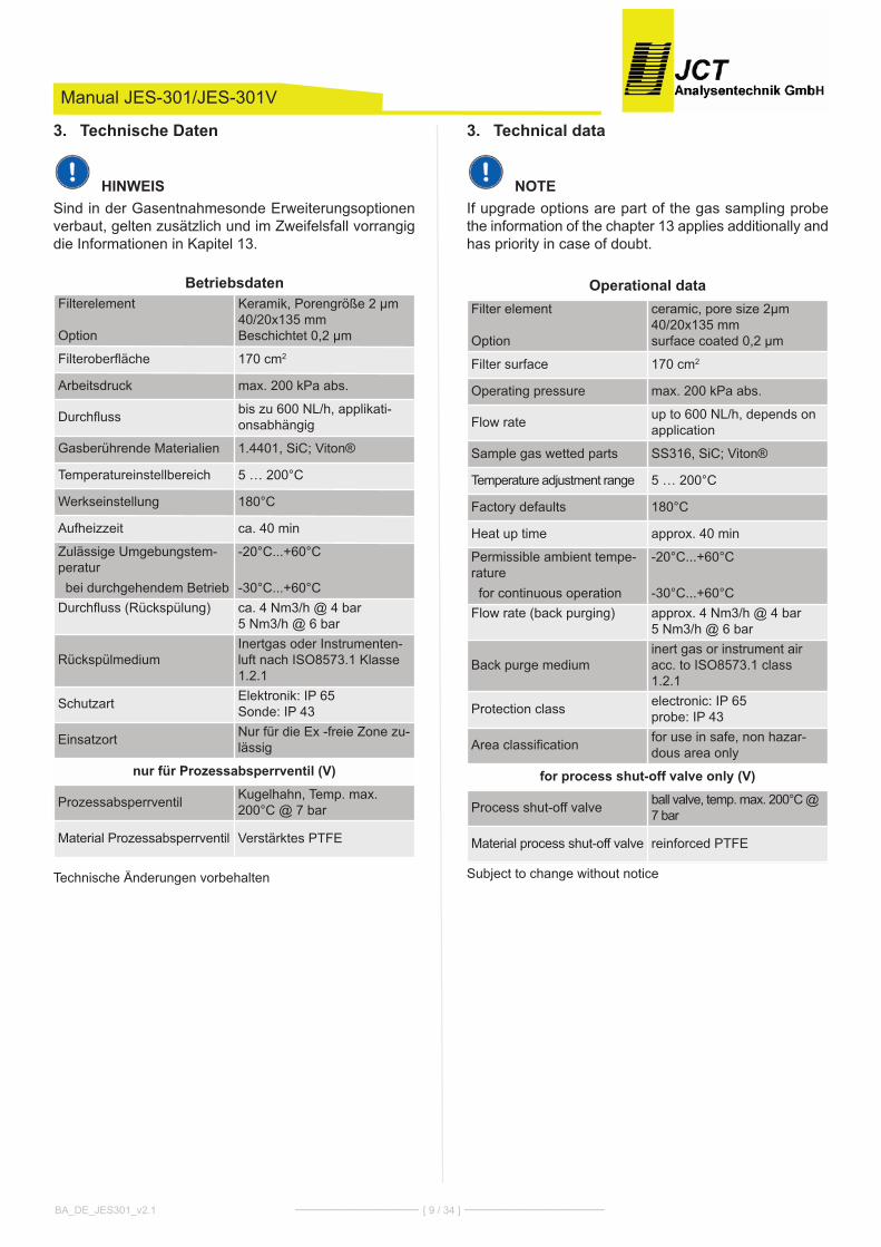
Technische Daten3.
HINWEISSind in der Gasentnahmesonde Erweiterungsoptionenverbaut, gelten zusätzlich und im Zweifelsfall vorrangigdie Informationen in kapitel 13.
Technische Änderungen vorbehalten
Technical data3.
NOTEIf upgrade options are part of the gas sampling probethe information of the chapter 13 applies additionally andhas priority in case of doubt.
Subject to change without notice
Manual JES-301/JES-301V
BA_DE_JES301_v2.1 ––––––––––––––– [ 9 / 34 ] –––––––––––––––––
BetriebsdatenFilterelement
Option
keramik, Porengröße 2 µm 40/20x135 mmBeschichtet 0,2 µm
Filteroberfläche 170 cm2
Arbeitsdruck max. 200 kPa abs.
Durchfluss bis zu 600 NL/h, applikati-onsabhängig
Gasberührende Materialien 1.4401, Sic; Viton®
Temperatureinstellbereich 5 … 200°c
Werkseinstellung 180°c
Aufheizzeit ca. 40 min
Zulässige Umgebungstem-peraturbei durchgehendem Betrieb
-20°c...+60°c
-30°c...+60°c Durchfluss (Rückspülung) ca. 4 Nm3/h @ 4 bar
5 Nm3/h @ 6 bar
RückspülmediumInertgas oder Instrumenten-luft nach ISO8573.1 klasse1.2.1
Schutzart Elektronik: IP 65Sonde: IP 43
Einsatzort Nur für die Ex -freie Zone zu-lässig
nur für Prozessabsperrventil (V)
Prozessabsperrventil kugelhahn, Temp. max.200°c @ 7 bar
Material Prozessabsperrventil Verstärktes PTFE
Operational dataFilter element
Option
ceramic, pore size 2µm40/20x135 mmsurface coated 0,2 µm
Filter surface 170 cm2
Operating pressure max. 200 kPa abs.
Flow rate up to 600 NL/h, depends onapplication
Sample gas wetted parts SS316, Sic; Viton®
Temperature adjustment range 5 … 200°c
Factory defaults 180°c
heat up time approx. 40 min
Permissible ambient tempe-raturefor continuous operation
-20°c...+60°c
-30°c...+60°cFlow rate (back purging) approx. 4 Nm3/h @ 4 bar
5 Nm3/h @ 6 bar
Back purge mediuminert gas or instrument airacc. to ISO8573.1 class1.2.1
Protection class electronic: IP 65probe: IP 43
Area classification for use in safe, non hazar-dous area only
for process shut-off valve only (V)
Process shut-off valve ball valve, temp. max. 200°c @7 bar
Material process shut-off valve reinforced PTFE
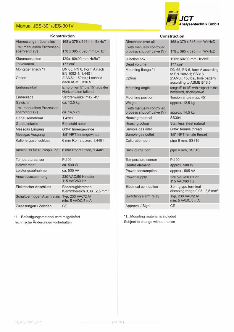
*1...Mounting material is includedSubject to change without notice
Manual JES-301/JES-301V
*1…Befestigungsmaterial wird mitgeliefertTechnische Änderungen vorbehalten
BA_DE_JES301_v2.1 ––––––––––––––– [ 10 / 34 ] –––––––––––––––––
KonstruktionAbmessungen über alles mit manuellem Prozessab-
sperrventil (V)
168 x 379 x 316 mm BxhxT
178 x 395 x 395 mm BxhxT
klemmenkasten 120x160x90 mm hxBxTTotvolumen 177 cm3
Montageflansch *1
Option
DN 65, PN 6, Form A nachEN 1092-1; 1.44012“ANSI; 150lbs.; Lochbildnach ASME B16.5
Einbauwinkel Empfohlen 5° bis 15° aus derhorizontalen fallend
Einbaulage Verdrehwinkel max. 45°Gewichtmit manuellem Prozessab-
sperrventil (V)
ca. 12,5 kg
ca. 14,5 kg
Gehäusematerial 1.4301Gehäusefarbe Edelstahl naturMessgas Eingang G3/4“ InnengewindeMessgas Ausgang 1/8“ NPT Innengewinde
kalibriergasanschluss 6 mm Rohrstutzen, 1.4401
Anschluss für Rückspülung 6 mm Rohrstutzen, 1.4401
Temperatursensor Pt100heizelement ca. 500 WLeistungsaufnahme ca. 505 VA
Anschlussspannung 230 VAc/50 hz oder 115 VAc/60 hz
Elektrischer Anschluss Federzugklemmenklemmbereich 0,08...2,5 mm2
Schaltvermögen Alarmrelais Typ. 230 VAc/2 A/min. 5 VADc/5 mA
Zulassungen / Zeichen cE
ConstructionDimension over allwith manually controlled
process shut-off valve (V)
168 x 379 x 316 mm WxhxD
178 x 395 x 395 mm WxhxD
Junction box 120x160x90 mm hxWxDDead volume 177 cm3
Mounting flange *1
Option
DN 65, PN 6, form A accordingto EN 1092-1; SS3162“ANSI; 150lbs., hole patternaccording to ASME B16.5
Mounting angle range 5° to 15° with respect to thehorizontal, sloping down
Mounting position Torsion angle max. 45°Weightwith manually controlled
process shut-off valve (V)
approx. 12,5 kg
approx. 14,5 kghousing material SS304housing colour Stainless steel naturalSample gas inlet G3/4“ female threadSample gas outlet 1/8" NPT female thread
calibration port pipe 6 mm, SS316
Back purge port pipe 6 mm, SS316
Temperature sensor Pt100heater element approx. 500 WPower consumption approx . 505 VA
Power supply 230 VAc/50 hz or 115 VAc/60 hz
Electrical connection Springtype terminal clamping range 0,08...2,5 mm2
Switching alarm relay Typ. 230 VAc/2 A/min. 5 VADc/5 mA
Approval / Sign cE
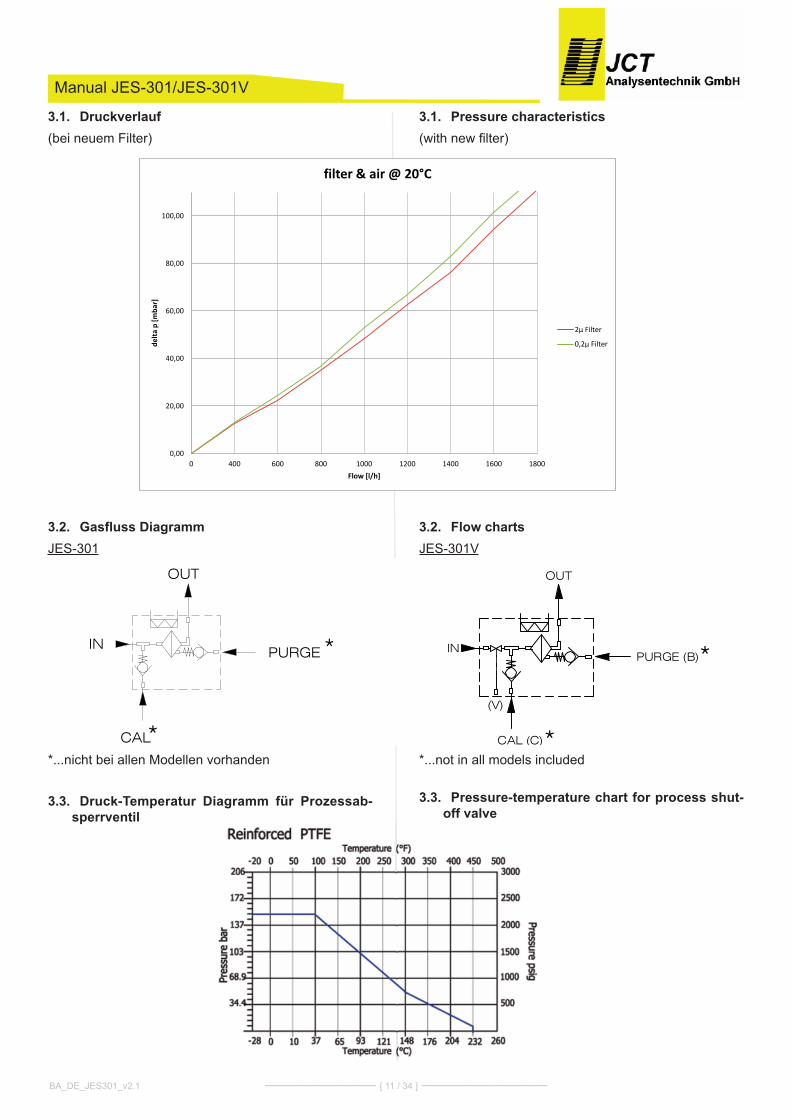
Pressure characteristics3.1.(with new filter)
Flow charts3.2.JES-301V
*...not in all models included
Pressure-temperature chart for process shut-3.3.off valve
Manual JES-301/JES-301V
Druckverlauf3.1.(bei neuem Filter)
Gasfluss Diagramm3.2.JES-301
*...nicht bei allen Modellen vorhanden
Druck-Temperatur Diagramm für Prozessab-3.3.sperrventil
BA_DE_JES301_v2.1 ––––––––––––––– [ 11 / 34 ] –––––––––––––––––
0,00
20,00
40,00
60,00
80,00
100,00
0 400 600 800 1000 1200 1400 1600 1800
delta
p [m
bar]
Flow [l/h]
filter & air @ 20°C
2µ Filter
0,2µ Filter
IN
OUT
CAL (C)*
*PURGE (B)
(V)
IN
OUT
CAL*
*PURGE

Installation, unpacking4.check instrument for any damage caused by shipping.If any damage is established, contact the carrier and dis-tributor immediately.
check instrument and any other parts against order.
Installation instructions5.Disconnect mains before working on electrical part•of equipment.The equipment has to be connected and grounded•according to the local rules and regulations.In order to guarantee safe operation the electronic•is equipped with interlocking under temperature mo-nitoring. For reset disconnect and connect poweragain.It is highly recommended to use the volt free status•contact. Only this assures a reliable operation of theprobe.It is essentially necessary to keep the electronics•away from radiant heating (thermal insulation). Theambient temperature must not exceed 60°c.The flange temperature must not exceed 200°c. Ot-•herwise a change of construction is necessery, eg.use of a thermal spacer.
The probe mounting has to be done always with a•minimum inclination of 5° towards the sampling pipe.This is necessary to prevent a possible flow backfrom condensate into the probe.
Mounting5.1.Mount probe with gasket on the process flange.•Take care for correct mounting angel according tech-•nical specification.Mount 1/8“ NPT male connector at sample gas out-•let.Attach heated sample line on probe enclosure with•moveable PG42 cable conduit or mounting clamp.connect the line with the connector fitting gas-tight.
PG 42 Mounting clamp
NOTEThe heated sample line must be strain relieved and mustnot be hung on the fitting
Manual JES-301/JES-301V
Installation, Sichtkontrolle4.Nach dem Auspacken ist das Gerät auf allfällige Trans-portschäden zu untersuchen. Wurde ein Schaden fest-gestellt, sind unverzüglich die verantwortliche Speditionund der händler zu benachrichtigen.Es ist zu überprüfen, ob die Gerätelieferung Ihrer Bestel-lung entspricht.
Installationsvorschriften5.Bei Arbeiten am elektrischen Teil des Gerätes ist es•vom Netz zu trennen.Das Gerät muss entsprechend den örtlich geltenden•Vorschriften angeschlossen und geerdet werden.Für einen sicheren Betrieb der Sonde ist diese mit•einer verriegelnd abschaltenden Untertemperatur-überwachung ausgestattet. Die Rücksetzung erfolgtdurch spannungsfrei Schalten der Elektronik.Der Betreiber ist angehalten, den potentialfreien•Statuskontakt zu benutzen bzw. zu überwachen.Nur dies gewährt einen sicheren Betrieb der Sonde.Es ist zwingend notwendig, die Elektronik vor Strah-•lungshitze zu schützen. (Thermische Isolation). Diemaximale Umgebungstemperatur darf 60°c nichtüberschreiten.Die Flanschtemperatur darf 200°c nicht überschrei-•ten, sonst ist eine konstruktive Änderung, z.B: Ein-satz eines Thermal Spacers, notwendig.Die Sonde muss immer mit einer Mindestneigung•von 5° gegen das Entnahmerohr hin montiert wer-den. Dies ist erforderlich um einen allfällig möglichenRückfluss des kondensates in die Entnahmesondezu verhindern.Montage5.1.
Sonde mit Dichtung am Prozessflansch montieren.•Einbauwinkel gemäß technischer Spezifikation be-•achten.1/8“ NPT Einschrauber am Messgas Ausgang mon-•tieren.Beheizte Messgasleitung mit verschiebbarer PG42•oder Montageschelle am Gehäuse befestigen undmit dem Einschrauber gasdicht verbinden.
PG 42 Montageschelle
HINWEISDie beheizte Messgasleitung muss zugentlastet werdenund darf nicht am Fitting abgehängt werden.
BA_DE_JES301_v2.1 ––––––––––––––– [ 12 / 34 ] –––––––––––––––––
� ��
�
+
++
+
+
+ +
+
++
� � � � � ������������������������������������ ++/��+����'��!%+9!�!+!'9+9����'+9���%���9+�'+����+9�!��'�+!��+���+�@�%0��>�+8��8����A+��+�6/$ + + + + + + + + + + + + + + + + + + + + + + + + +
+ + + +
+
+
+ +
+ + +
++
++
+++
+�
��
��
��
�
+ + + + +
+ +
+ +
+ + + + + + +
+ + + + + + +
+ + + + + + +
+ + +
+ + + + +
+ + + +
� � � �����������
� � � ����������
� � � ��������
� ��
�
+
++
+
+
+ +
+
++
� � � � � ������������������������������������ ++ + + + + + + + + + + + + + ++ + + + + + + + + + + + + + + + + + + + + + + + +
+ + + +
+
+
+ +
+ + +
++
++
+++
+�
��
��
��
�
+ + + + +
+ +
+ +
+ + + + + + +
+ + + + + + +
+ + + + + + +
+ + +
+ + + + +
+ + + +
� � � �
� � � �
� � � �
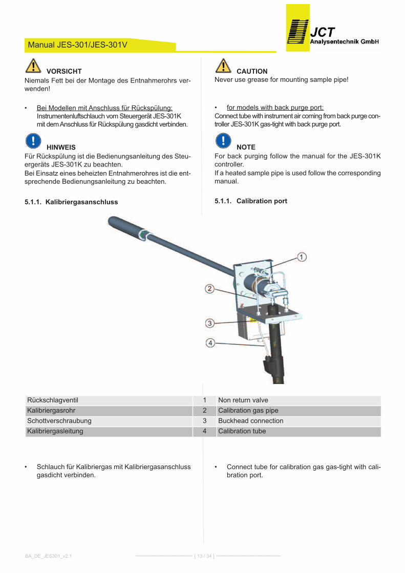
CAUTIONNever use grease for mounting sample pipe!
for models with back purge port:•connect tube with instrument air coming from back purge con-troller JES-301k gas-tight with back purge port.
NOTEFor back purging follow the manual for the JES-301kcontroller.If a heated sample pipe is used follow the correspondingmanual.
Calibration port 5.1.1.
connect tube for calibration gas gas-tight with cali-•bration port.
Manual JES-301/JES-301V
VORSICHTNiemals Fett bei der Montage des Entnahmerohrs ver-wenden!
Bei Modellen mit Anschluss für Rückspülung:•Instrumentenluftschlauch vom Steuergerät JES-301kmit dem Anschluss für Rückspülung gasdicht verbinden.
HINWEISFür Rückspülung ist die Bedienungsanleitung des Steu-ergeräts JES-301k zu beachten.Bei Einsatz eines beheizten Entnahmerohres ist die ent-sprechende Bedienungsanleitung zu beachten.
Kalibriergasanschluss 5.1.1.
Schlauch für kalibriergas mit kalibriergasanschluss•gasdicht verbinden.
BA_DE_JES301_v2.1 ––––––––––––––– [ 13 / 34 ] –––––––––––––––––
Rückschlagventil 1 Non return valvekalibriergasrohr 2 calibration gas pipeSchottverschraubung 3 Buckhead connectionkalibriergasleitung 4 calibration tube
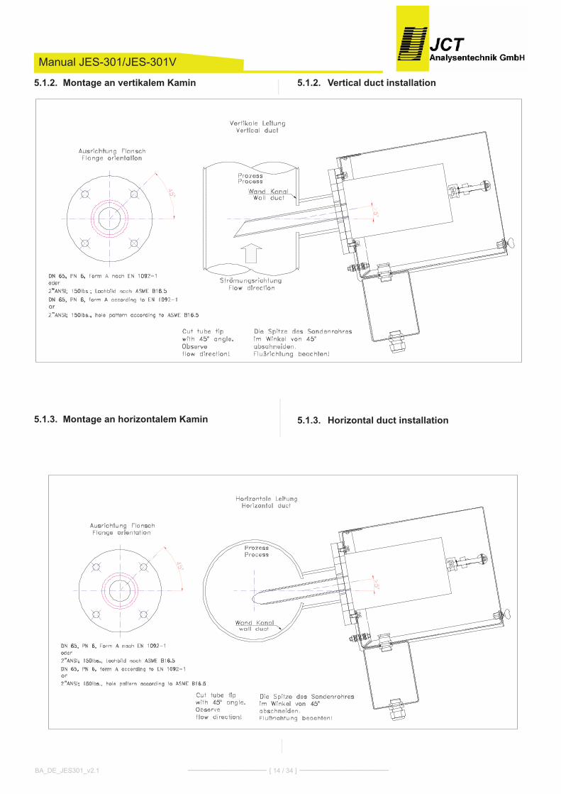
Vertical duct installation5.1.2.
Horizontal duct installation5.1.3.
Manual JES-301/JES-301V
Montage an vertikalem Kamin5.1.2.
Montage an horizontalem Kamin5.1.3.
BA_DE_JES301_v2.1 ––––––––––––––– [ 14 / 34 ] –––––––––––––––––
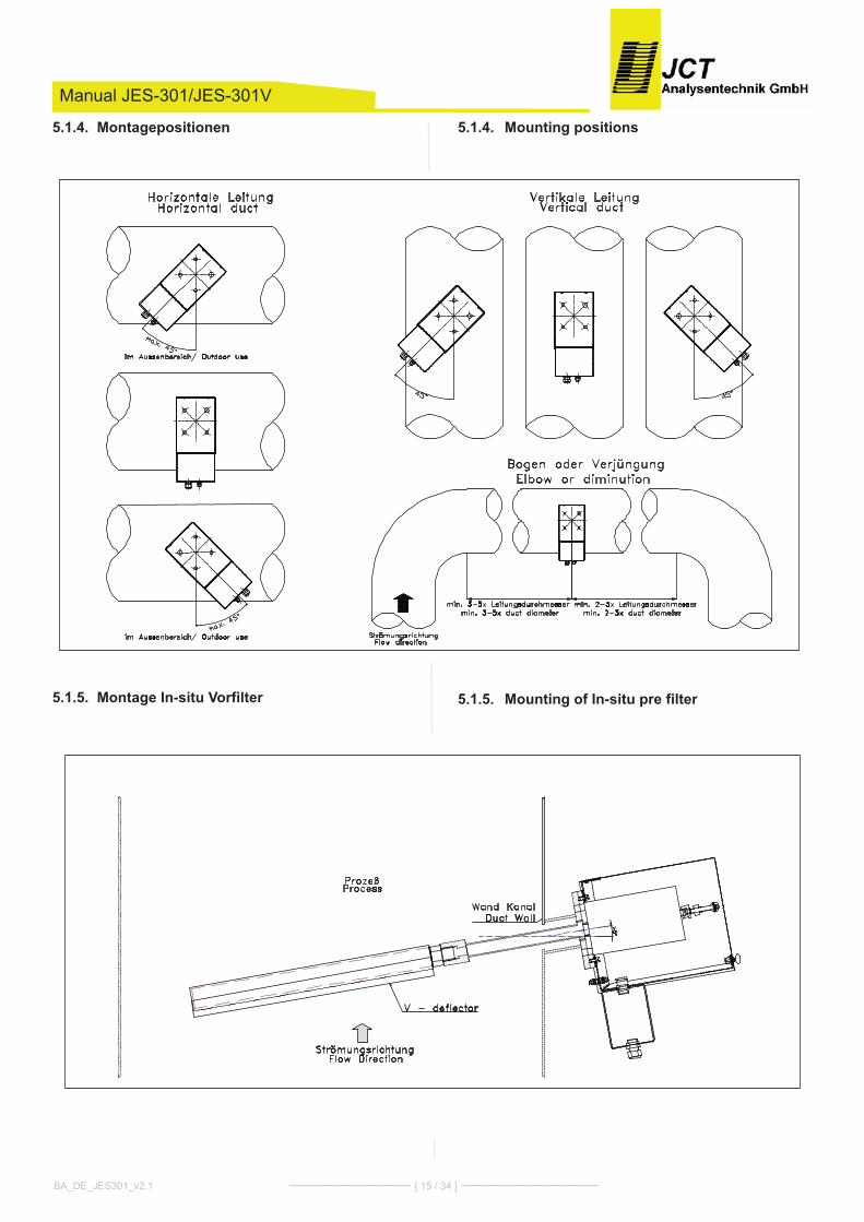
Mounting positions5.1.4.
Mounting of In-situ pre filter5.1.5.
Manual JES-301/JES-301V
Montagepositionen5.1.4.
Montage In-situ Vorfilter5.1.5.
BA_DE_JES301_v2.1 ––––––––––––––– [ 15 / 34 ] –––––––––––––––––
Electrical connections5.2.check local voltage, frequency and power consump-•tion against type plate.connect a 2-pole switch in mains supply; the sample•probe is not equipped with a switch.The equipment has to be connected and additionally•grounded with a wire of sufficient diameter on theground connection of the housing according to thelocal rules and regulations.Always operate contacts within specified ratings. For•connection of inductive and capacitive loads usesuitable protection circuits (f.i. recovery diodes forinductive and serial resistance for capacitive loads).Relays are illustrated in current- less conditions (failsafe).The operator must provide suitable stress relief•
NOTEFor the connection of a temperature controller see chap-ter 9.For the connection of a junction box see chapter 8.
CAUTIONThis unit is operated with mains power. During operationsome parts of the unit are energised with dangerous volt-age!During operation the housing of the probe can get veryhot. Removing the probe housing will expose heatedparts. Disconnect power before repair or maintenanceand ensure that the internal temperature has dropped toa safe level before working on it. Always wear heat re-sistant gloves. There is burn hazard if necessary precau-tionary steps are not taken.This unit is not intended for use in explosion hazardousareas or with explosive or flammable gases and mustnot be operated under these conditions.If these warning notices are ignored possible serious in-juries and/or damages may be caused.
Only qualified staff who has been trained according tothis manual should operate and maintain this instrument.For certain and safe operation the instrument needs tobe transported carefully, be part of a well planned appli-cation, installed correctly as well as operated and main-tained according to these instructions.
Manual JES-301/JES-301V
Elektrischer Anschluss5.2.Örtliche Netzspannung, Netzfrequenz und Leis-•tungsaufnahme mit den Angaben am Typenschildvergleichen.In der Energieversorgungszuführung ist ein 2-poli-•ger Netzschalter einzubauen, die Sonde besitzt kei-nen eigenen Netzschalter.Das Gerät muss entsprechend den örtlich geltenden•Vorschriften angeschlossen, sowie zusätzlich überden Erdungsanschluss am Gehäuse, mit einem Lei-ter ausreichenden Querschnitts geerdet werden.Die kontakte sind zu jeder Zeit innerhalb der spezi-•fizierten Werte zu betreiben. Induktive und kapazi-tive Lasten sind mit entsprechendenSchutzmaßnahmen anzuschließen (z.B. Freilaufdio-den bei induktive Lasten und Serienwiderstände beikapazitiven Lasten). Relais sind in stromlosen Zu-stand (Fail safe) dargestellt.Der Betreiber muss eine entsprechende Zugentlas-•tung der kabel gewährleisten.
HINWEISFür den Anschluss eines Temperaturreglers siehe kapi-tel 9.Für den Anschluss einer klemmenbox siehe kapitel 8.
VORSICHTDieses Gerät wird mit Netzspannung betrieben. BeimBetrieb dieses Gerätes stehen zwangsläufig bestimmteTeile dieses Gerätes unter gefährlicher Spannung!Im Betrieb kann das Gehäuse der Sonde sehr heiß wer-den. Durch Abnahme des Gehäuses werden heiße Teilezugänglich. Bei jeglichen Arbeiten an der Sonde ist dasGerät abzuschalten, die Abkühlung abzuwarten und injedem Fall sind Schutzhandschuhe zu tragen. Beim Be-rühren der internen Teile der Sonde besteht Verbren-nungsgefahr.Dieses Gerät darf nicht in explosionsgefährdeten Berei-chen oder mit zündfähigen und leicht entflammbarenGasen betrieben werden.Bei Nichtbeachtung der Warnhinweise können schwerePersonenschäden und/oder Sachschäden auftreten.
Nur entsprechend qualifiziertes und geschultes Personaldarf an diesem Gerät oder in dessen Nähe arbeiten.Dieses Personal muss mit allen Warnungen und In-standhaltungs - Maßnahmen gemäß dieser Betriebs-an-leitung vertraut sein.Der einwandfreie und sichere Betrieb dieses Gerätessetzt sachgemäßen Transport, fachgerechte Lagerung,Aufstellung und Montage sowie sorgfältige Bedienung
BA_DE_JES301_v2.1 ––––––––––––––– [ 16 / 34 ] –––––––––––––––––

Requirements for qualifications of staff:Qualified staff in the sense of this manual and/or thewarning references are persons, who are familiar withassembly, mounting, start-up and operating of this prod-uct and have sufficient qualification for their tasks.
Start up6.1. check of the proper installation2. Review the equipment for damage3. Make sure that the process shut-off valve (op-
tion) is closed (i.e. set at right angle to the longi-tudinal axis of the probe).
4. check for leaks.
CAUTIONBefore switching on sample probe ensure that the oper-ating voltage of the unit and the line voltage are identi-cal.5. Switch on the power supply of the sample probe.
After a lead time of approx. 40 min set tempera-ture will be reached. As long as the temperatureis below the set value the fault indication contactindicates alarm. (Alarm indication: open contact)
6. Turn t-handle of process shut-off valve (option)by 90° to open it (ie. t-handle stands in line withprobe).
NOTEAny smell at the first time heat up is normal and is noreason for a warranty claim.New filter elements and sealings may influence the mea-surement results. It is recommended to purge the gassampling probe diligently in heated condition.
NOTEFor back purging follow the manual for the JES-301kcontroller.
NOTEWith the back purge pulses the filter is cleaned from theinside to the outside. Therefore some dust may remainin the filter housing. This is normal and does not harmthe function of the probe in any way.
Manual JES-301/JES-301V
und Instandhaltung voraus.
Anforderungen an die Qualifikation des Personals:Qualifiziertes Personal im Sinne dieser Betriebsanlei-tung bzw. der Warnhinweise sind Personen, die mit Auf-stellung, Montage, Inbetriebsetzung und Betrieb diesesProduktes vertraut sind und die über eine ihrer Tätigkeitentsprechenden Qualifikation verfügen.
Inbetriebnahme6.1. kontrolle der vorschriftsgemäßen Installation2. Überprüfung des Gerätes auf Beschädigung3. Sicherstellen, dass das Prozessabsperrventil
(Option) geschlossen ist (dh. quer zur Sonden Längsachse steht).
4. Dichtheitsprüfung durchführen.
VORSICHTVor dem Einschalten ist sicherzustellen, dass die amGerät eingestellte Betriebsspannung und die Netzspan-nung übereinstimmen.5. Energieversorgung der Sonde einschalten.
Nach einer Vorlaufzeit von ca. 40 min ist die ein-gestellte Betriebstemperatur erreicht. Solangedie Sonde den eingestellten Grenzwert nichtüberschritten hat, signalisiert der Störmeldekon-takt den Alarmzustand. (Alarmzustand: kontaktgeöffnet)
6. Prozessabsperrventil (Option) durch Drehen desT-Griffs um 90° öffnen. (dh. T-Griff steht in einerAchse mit dem Sondenkörper)
HINWEISAllfällige Geruchsbildung beim erstmaligen Aufheizen istnormal und stellt keinen Gewährleistungsanspruch dar.Neue Filterelemente und Dichtungen können in den ers-ten Stunden die Messergebnisse beeinflussen. Es wirdempfohlen, die Gasentnahmesonde in aufgeheiztem Zu-stand ausreichend zu spülen.
HINWEISFür Rückspülung ist die Bedienungsanleitung des Steu-ergeräts zur Rückspülung JES-301k zu beachten.
HINWEISDie Rückspülung des Filters erfolgt von innen nachaußen. Daher kann etwas Staub im Filterghäuse zurück-bleiben. Das ist normal und beeinträchtigt die Funktionder Entnahmesonde nicht.
BA_DE_JES301_v2.1 ––––––––––––––– [ 17 / 34 ] –––––––––––––––––

Feeding of calibration gas:1. Feed calibration gas with minor over pressure (ap-prox. 2l/min more than sample gas flow) into calibrationport.2. Excess calibration gas flows off into the process.
Maintenance and service7.
NOTEIf an item is returned to JcT Analysentechnik, for main-tenance or repair reasons, it will only be accepted afterthe RMA form on our website has been completed(www.jct.at/rma). This is to ensure the security of JcTstaff.
RecyclingThe unit contains elements which are suitable for recy-cling, and components which need special disposal. youare therefore requested to make sure that the unit willbe recycled by the end of its service life.
Replacement of filter element7.1.Filter elements, O-rings and gaskets are consumablesand have to be replaced regularly, at least once a year.Ensure that sealing surfaces are clean and unheart
NOTEThe ceramic filter elements are very fragile by their na-ture. handle those elements with care and avoid drop-ping them.
Burn hazard!Use heat resistant gloves.
CAUTIONThe housing of the probe may get very hot!Take care, in case of process over pressure, explosiveand/or toxic gas emanation is possible.To avoid accidents take care for necessary safety pre-cautions in case of service and maintenance.
NOTEDo not use earthing cable to hold weight of housingcover.
Manual JES-301/JES-301V
Aufgabe von kalibriergas:1. kalibriergas mit leichtem Überdruck (ca. 2l/min überDruck des Messgasstroms) in kalibriergasanschlusseinströmen lassen.2. Abströmen des überschüssigen kalibriergases erfolgtin den Prozess.
Wartung und Service7.
HINWEISIst es zu Wartungs- oder Reparaturzwecken notwendig,das Gerät an JcT Analysentechnik zu schicken, ist dasRMA-Formular auf der Website vollständig auszufüllen(www.jct.at/rma). Andernfalls kann das Gerät zumSchutz der JcT Mitarbeiter nicht übernommen werden.
RecyclingDas Gerät enthält Bauteile, die wiederverwertet werdenkönnen, sowie Bauteile, die speziell entsorgt werdenmüssen. Sorgen Sie deshalb dafür, dass das Gerät nachder Verwendung der Wiederverwertung zugeführt wird.
Ersetzen des Filterelementes7.1.Filterelemente und Dichtungen sind Verbrauchsteile undsind abhängig von den Einsatzbedingungen regelmäßig,mind. 1mal pro Jahr zu warten. Es ist sicherzustellen,dass die Dichtflächen sauber und unversehrt sind.
HINWEISDie keramikfilterelemente sind von ihrer Beschaffenheitsehr zerbrechlich. Daher die Elemente vorsichtig hand-haben und nicht fallen lassen.
Verbrennungsgefahr!hitzebeständige handschuhe benutzen.
VORSICHTDas Gehäuse der Sonde kann sehr heiß sein!Bei Prozessüberdruck können explosive und/oder toxi-sche Gase austreten.Entsprechende Maßnahmen sind bei Wartung und Ser-vice sowie Ersetzen oder Reinigen des Filterelementeszu treffen.
HINWEISGehäusedeckel nicht am Erdungsband abhängen.
BA_DE_JES301_v2.1 ––––––––––––––– [ 18 / 34 ] –––––––––––––––––

For cleaning or replacing following steps should bedone:
close process shut-off valve (option)1.Switch off the power supply and wait for cooling2.down of the probe.Remove the weather protection housing.3.Turn away the handle (pos. 21) for pulling out the4.filter element. Swing the pivoting lever sideways andpull out the support tube with the filter element.Loosen tighten piston (pos. 6) from the support5.tube (pos. 9). Pull out filter element and gaskets.
Replace filter element (pos. 8) and/or gaskets (pos.6.7). clean groove on tighting piston of filter retainer(pos. 10) and remove O-rings (pos. 11 and 12) witha non-metallic tool (wood or plastic wedge).
Apply a thin wetting of PTFE paste on O-rings and7.pull them on.Remount gaskets (pos. 7) and filter element (pos.8.8).Screw on the filter element-screw (pos. 6).9.clean the sealing surfaces in sample probe.10.Mount all other parts in vice versa sequence.11.
NOTEAny smell at the first time heat up is normal and is noreason for a warranty claim.New filter elements and sealings may influence the mea-surement results. It is recommended to purge the gassampling probe diligently in heated condition.
Connection of a junction box8.If no temperature controller is connected directly, all con-nections and contacts are available in a junction box.
Electrical connection (junction box)8.1.
Connection of spring type terminal8.2.Open spring with a suitable tool (2,5 x 0,4 mm).•Insert cable.•Release spring.•
Manual JES-301/JES-301V
Für den Ersatz der Filterelemente sind folgende Schrittevorzunehmen:
Prozessabsperrventil (Option) schließen.1.Elektrische Zuleitung abschalten und warten bis die2.Sonde abgekühlt ist.Wetterschutzhaube abnehmen.3.Durch Drehen des Griffs (Pos. 21) das Filterelement4.herausziehen. Schwenkarm zur Seite klappen undFilterkolben herausziehen.Filterelementverschraubung (Pos. 6) vom Träger-5.element (Pos. 9) lösen. Filterelement und Flach-dichtungen herausnehmen.Filter (Pos. 8) und/oder Flachdichtungen (Pos. 7) er-6.setzen. Nut am Dichtkolben des Filterhalter Träger-elements (Pos. 10) reinigen und die zwei O-Ringemit einem nicht metallischen Werkzeug (holz- oderkunststoffkeil) entfernen (Pos. 11 und 12).Neue O-Ringe dünn mit PTFE-Paste benetzen und7.aufziehen. Flachdichtungen (Pos. 7) und Filter (Pos. 8) montie-8.ren.Filterelementverschraubung festziehen (Pos. 6).9.Dichtungsflächen in der Sonde reinigen.10.Anschließend erfolgt Montage in umgekehrter Rei-11.
henfolge.
HINWEISNeue Filterelemente und Dichtungen können in den ers-ten Stunden die Messergebnisse beeinflussen. Es wirdempfohlen, die Gasentnahmesonde in aufgeheiztem Zu-stand ausreichend zu spülen.
Anschluss einer Klemmenbox8.Wenn nicht direkt ein Temperaturregler angeschlossenwird, stehen alle Anschlüsse und kontakte in einer klem-menbox zur Verfügung.
Elektrischer Anschluss (Klemmenbox)8.1.
Anschluss von Federzugklemmen8.2.Feder mit geeignetem Betätigungswerkzeug (2,5 x•0,4 mm) öffnen.Leiter einführen.•Feder entlasten.•
BA_DE_JES301_v2.1 ––––––––––––––– [ 19 / 34 ] –––––––––––––––––
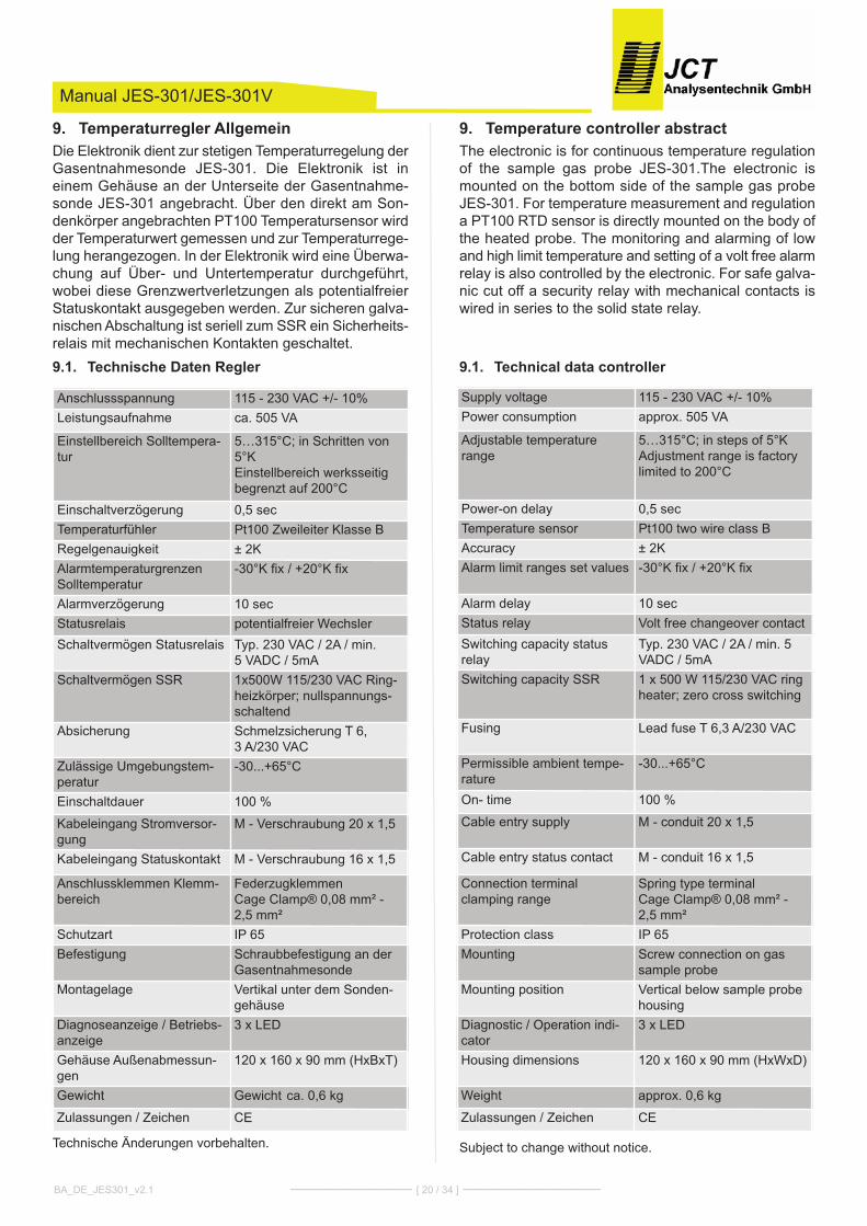
Temperature controller abstract9.The electronic is for continuous temperature regulationof the sample gas probe JES-301.The electronic ismounted on the bottom side of the sample gas probeJES-301. For temperature measurement and regulationa PT100 RTD sensor is directly mounted on the body ofthe heated probe. The monitoring and alarming of lowand high limit temperature and setting of a volt free alarmrelay is also controlled by the electronic. For safe galva-nic cut off a security relay with mechanical contacts iswired in series to the solid state relay.
Technical data controller9.1.
Subject to change without notice.
Manual JES-301/JES-301V
Temperaturregler Allgemein9.Die Elektronik dient zur stetigen Temperaturregelung derGasentnahmesonde JES-301. Die Elektronik ist ineinem Gehäuse an der Unterseite der Gasentnahme-sonde JES-301 angebracht. Über den direkt am Son-denkörper angebrachten PT100 Temperatursensor wirdder Temperaturwert gemessen und zur Temperaturrege-lung herangezogen. In der Elektronik wird eine Überwa-chung auf Über- und Untertemperatur durchgeführt,wobei diese Grenzwertverletzungen als potentialfreierStatuskontakt ausgegeben werden. Zur sicheren galva-nischen Abschaltung ist seriell zum SSR ein Sicherheits-relais mit mechanischen kontakten geschaltet.
Technische Daten Regler9.1.
Technische Änderungen vorbehalten.
BA_DE_JES301_v2.1 ––––––––––––––– [ 20 / 34 ] –––––––––––––––––
Anschlussspannung 115 - 230 VAc +/- 10%Leistungsaufnahme ca. 505 VA
Einstellbereich Solltempera-tur
5…315°c; in Schritten von5°kEinstellbereich werksseitigbegrenzt auf 200°c
Einschaltverzögerung 0,5 secTemperaturfühler Pt100 Zweileiter klasse BRegelgenauigkeit ± 2kAlarmtemperaturgrenzenSolltemperatur
-30°k fix / +20°k fix
Alarmverzögerung 10 secStatusrelais potentialfreier WechslerSchaltvermögen Statusrelais Typ. 230 VAc / 2A / min.
5 VADc / 5mASchaltvermögen SSR 1x500W 115/230 VAc Ring-
heizkörper; nullspannungs-schaltend
Absicherung Schmelzsicherung T 6, 3 A/230 VAc
Zulässige Umgebungstem-peratur
-30...+65°c
Einschaltdauer 100 %
kabeleingang Stromversor-gung
M - Verschraubung 20 x 1,5
kabeleingang Statuskontakt M - Verschraubung 16 x 1,5
Anschlussklemmen klemm-bereich
Federzugklemmencage clamp® 0,08 mm² -2,5 mm²
Schutzart IP 65Befestigung Schraubbefestigung an der
GasentnahmesondeMontagelage Vertikal unter dem Sonden-
gehäuseDiagnoseanzeige / Betriebs-anzeige
3 x LED
Gehäuse Außenabmessun-gen
120 x 160 x 90 mm (hxBxT)
Gewicht Gewicht ca. 0,6 kg
Zulassungen / Zeichen cE
Supply voltage 115 - 230 VAc +/- 10%Power consumption approx. 505 VA
Adjustable temperaturerange
5…315°c; in steps of 5°kAdjustment range is factorylimited to 200°c
Power-on delay 0,5 secTemperature sensor Pt100 two wire class BAccuracy ± 2kAlarm limit ranges set values -30°k fix / +20°k fix
Alarm delay 10 secStatus relay Volt free changeover contactSwitching capacity statusrelay
Typ. 230 VAc / 2A / min. 5VADc / 5mA
Switching capacity SSR 1 x 500 W 115/230 VAc ringheater; zero cross switching
Fusing Lead fuse T 6,3 A/230 VAc
Permissible ambient tempe-rature
-30...+65°c
On- time 100 %
cable entry supply M - conduit 20 x 1,5
cable entry status contact M - conduit 16 x 1,5
connection terminal clamping range
Spring type terminalcage clamp® 0,08 mm² -2,5 mm²
Protection class IP 65Mounting Screw connection on gas
sample probeMounting position Vertical below sample probe
housingDiagnostic / Operation indi-cator
3 x LED
housing dimensions 120 x 160 x 90 mm (hxWxD)
Weight approx. 0,6 kg
Zulassungen / Zeichen cE
CAUTIONReplace fuse always with same type and rating!
Power supply9.2.The unit is equipped with a wide range power supplywhich allows a supply range from 90 to 230 VAc.
CAUTIONThe ring heater element must be suitable for the re-
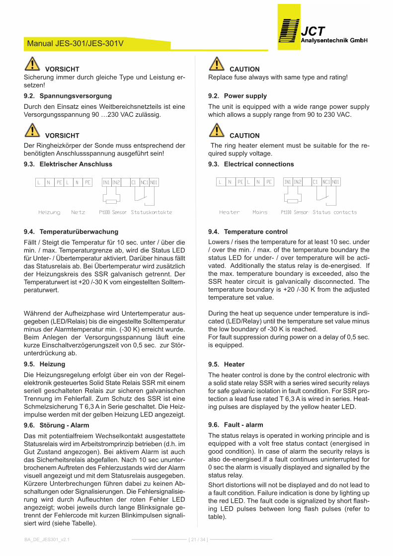
quired supply voltage.Electrical connections9.3.
Temperature control9.4.Lowers / rises the temperature for at least 10 sec. under/ over the min. / max. of the temperature boundary thestatus LED for under- / over temperature will be acti-vated. Additionally the status relay is de-energised. Ifthe max. temperature boundary is exceeded, also theSSR heater circuit is galvanically disconnected. Thetemperature boundary is +20 /-30 k from the adjustedtemperature set value.
During the heat up sequence under temperature is indi-cated (LED/Relay) until the temperature set value minusthe low boundary of -30 k is reached. For fault suppression during power on a delay of 0,5 sec.is equipped.
Heater9.5.The heater control is done by the control electronic witha solid state relay SSR with a series wired security relaysfor safe galvanic isolation in fault condition. For SSR pro-tection a lead fuse rated T 6,3 A is wired in series. heat-ing pulses are displayed by the yellow heater LED.
Fault - alarm9.6.The status relays is operated in working principle and isequipped with a volt free status contact (energised ingood condition). In case of alarm the security relays isalso de-energised.If a fault continues uninterrupted for0 sec the alarm is visually displayed and signalled by thestatus relay.Short distortions will not be displayed and do not lead toa fault condition. Failure indication is done by lighting upthe red LED. The fault code is signalized by short flash-ing LED pulses between long flash pulses (refer totable).
Manual JES-301/JES-301V
VORSICHTSicherung immer durch gleiche Type und Leistung er-setzen!
Spannungsversorgung9.2.Durch den Einsatz eines Weitbereichsnetzteils ist eineVersorgungsspannung 90 …230 VAc zulässig.
VORSICHTDer Ringheizkörper der Sonde muss entsprechend derbenötigten Anschlussspannung ausgeführt sein!
Elektrischer Anschluss9.3.
Temperaturüberwachung9.4.Fällt / Steigt die Temperatur für 10 sec. unter / über diemin. / max. Temperaturgrenze ab, wird die Status LEDfür Unter- / Übertemperatur aktiviert. Darüber hinaus fälltdas Statusrelais ab. Bei Übertemperatur wird zusätzlichder heizungskreis des SSR galvanisch getrennt. DerTemperaturwert ist +20 /-30 k vom eingestellten Solltem-peraturwert.
Während der Aufheizphase wird Untertemperatur aus-gegeben (LED/Relais) bis die eingestellte Solltemperaturminus der Alarmtemperatur min. (-30 k) erreicht wurde.Beim Anlegen der Versorgungsspannung läuft einekurze Einschaltverzögerungszeit von 0,5 sec. zur Stör-unterdrückung ab.
Heizung9.5.Die heizungsregelung erfolgt über ein von der Regel-elektronik gesteuertes Solid State Relais SSR mit einemseriell geschalteten Relais zur sicheren galvanischenTrennung im Fehlerfall. Zum Schutz des SSR ist eineSchmelzsicherung T 6,3 A in Serie geschaltet. Die heiz-impulse werden mit der gelben heizung LED angezeigt.
Störung - Alarm9.6.Das mit potentialfreiem Wechselkontakt ausgestatteteStatusrelais wird im Arbeitstromprinzip betrieben (d.h. imGut Zustand angezogen). Bei aktivem Alarm ist auchdas Sicherheitsrelais abgefallen. Nach 10 sec ununter-brochenem Auftreten des Fehlerzustands wird der Alarmvisuell angezeigt und mit dem Statusrelais ausgegeben.kürzere Unterbrechungen führen dabei zu keinen Ab-schaltungen oder Signalisierungen. Die Fehlersignalisie-rung wird durch Aufleuchten der roten Fehler LEDangezeigt; wobei jeweils durch lange Blinksignale ge-trennt der Fehlercode mit kurzen Blinkimpulsen signali-siert wird (siehe Tabelle).
BA_DE_JES301_v2.1 ––––––––––––––– [ 21 / 34 ] –––––––––––––––––
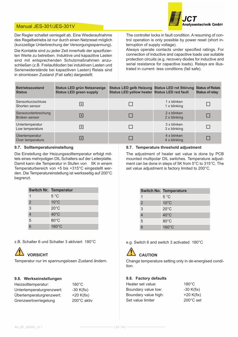
The controller locks in fault condition. A resuming of con-trol operation is only possible by power reset (short in-terruption of supply voltage).Always operate contacts under specified ratings. Forconnection of inductive and capacitive loads use suitableprotection circuits (e.g. recovery diodes for inductive andserial resistance for capacitive loads). Relays are illus-trated in current- less conditions (fail safe).
Temperature threshold adjustment9.7.The adjustment of heater set value is done by PcBmounted multipolar DIL switches. Temperature adjust-ment can be done in steps of 5k from 5°c to 315°c. Theset value adjustment is factory limited to 200°c.
e.g. Switch 6 and switch 3 activated Ë180°c
CAUTIONchange temperature setting only in de-energised condi-tion.
Factory defaults9.8.heater set value: 180°cBoundary value low: -30 k(fix)Boundary value high: +20 k(fix)Set value limiter 200°c set
Switch No. Temperature1 5 °c2 10°c3 20°c4 40°c5 80°c6 160°c
Manual JES-301/JES-301V
Der Regler schaltet verriegelt ab. Eine Wiederaufnahmedes Regelbetriebs ist nur durch einen Netzreset möglich(kurzzeitige Unterbrechung der Versorgungsspannung).Die kontakte sind zu jeder Zeit innerhalb der spezifizier-ten Werte zu betreiben. Induktive und kapazitive Lastensind mit entsprechenden Schutzmaßnahmen anzu-schließen (z.B. Freilaufdioden bei induktiven Lasten undSerienwiderstände bei kapazitiven Lasten) Relais sindin stromlosen Zustand (Fail safe) dargestellt.
Solltemperatureinstellung9.7.Die Einstellung der heizungssolltemperatur erfolgt mit-tels eines mehrpoligen DIL Schalters auf der Leiterplatte.Damit kann die Temperatur in Stufen von 5k in einemTemperaturbereich von +5 bis +315°c eingestellt wer-den. Die Temperatureinstellung ist werksseitig auf 200°cbegrenzt.
z.B. Schalter 6 und Schalter 3 aktiviert Ë180°c
VORSICHTTemperatur nur im spannungslosen Zustand ändern.
Werkseinstellungen9.8.heizsolltemperatur: 180°cUntertemperaturgrenzwert: -30 k(fix)Übertemperaturgrenzwert: +20 k(fix)Grenzwertverriegelung 200°c aktiv
Switch Nr. Temperatur1 5 °c2 10°c3 20°c4 40°c5 80°c6 160°c
BA_DE_JES301_v2.1 ––––––––––––––– [ 22 / 34 ] –––––––––––––––––
BetriebszustandStatus
Status LED grün NetzanzeigeStatus LED green supply
Status LED gelb HeizungStatus LED yellow heater
Status LED rot StörungStatus LED red fault
Status of RelaisStatus of relay
SensorkurzschlussShorten sensor x 1 x blinken
1 x blinking
SensorunterbrechungBroken sensor x 2 x blinken
2 x blinking
UntertemperaturLow temperature x 3 x blinken
3 x blinking
ÜbertemperaturOver temperature x 4 x blinken
4 x blinking
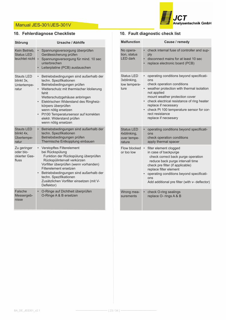
Fault diagnostic check list10.
Malfunction Cause / remedy
No opera-tion, statusLED dark
• check internal fuse of controller and sup-ply
• disconnect mains for at least 10 sec • replace electronic board (PcB)
Status LED3xblinking,low tempera-ture
• operating conditions beyond specificati-onscheck operation conditions
• weather protection with thermal isolationnot appliedmount weather protection cover
• check electrical resistance of ring heaterreplace if necessary
• check Pt 100 temperature sensor for cor-rect resistancereplace if necsesary
Status LED4xblinking,over tempe-rature
• operating conditions beyond specificati-onscheck operation conditionsapply thermal spacer
Flow blockedor too low
• filter element cloggedin case of backpurgecheck correct back purge operation reduce back purge intervall time
check pre filter (if applicable) replace filter element
• operating conditions beyond specificati-onsAdd additional pre filter (with v- deflector)
Wrong mea-surements
• check O-ring sealingsreplace O- rings A & B
Manual JES-301/JES-301V
Fehlerdiagnose Checkliste10.
Störung Ursache / Abhilfe
kein Betrieb,Status LEDleuchtet nicht
• Spannungsversorgung überprüfenGerätesicherung prüfen
• Spannungsversorgung für mind. 10 secunterbrechen
• Leiterplatine (PcB) austauschen
Stauts LEDblinkt 3x,Untertempe-ratur
• Betriebsbedingungen sind außerhalb dertechn. SpezifikationenBetriebsbedingungen prüfen
• Wetterschutz mit thermischer IdolierungfehltWetterschutzgehäuse anbringen
• Elektrischen Widerstand des Ringheiz-körpers überprüfenwenn nötig ersetzen
• Pt100 Temperatursensor auf korrektenelektr. Widerstand prüfenwenn nötig ersetzen
Stauts LEDblinkt 4x,Übertempe-ratur
• Betriebsbedingungen sind außerhalb dertechn. SpezifikationenBetriebsbedingungen prüfenThermische Entkopplung einbauen
Zu geringeroder blo-ckierter Gas-fluss
• Verstopftes Filterelementbei RückspülungFunktion der Rückspülung überprüfenRückspülintervall verkürzen
Vorfilter überprüfen (wenn vorhanden)Filterelement ersetzen
• Betriebsbedingungen sind außerhalb dertechn. SpezifikationenZusätzlichen Vorfilter einsetzen (mit V-Deflektor)
FalscheMessergeb-nisse
• O-Ringe auf Dichtheit überprüfenO-Ringe A & B ersetzen
BA_DE_JES301_v2.1 ––––––––––––––– [ 23 / 34 ] –––––––––––––––––
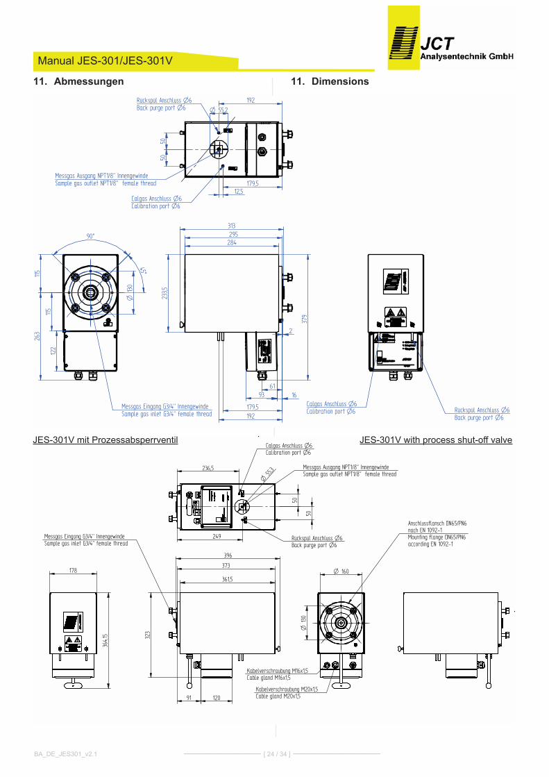
Dimensions11.
Manual JES-301/JES-301V
Abmessungen11.
BA_DE_JES301_v2.1 ––––––––––––––– [ 24 / 34 ] –––––––––––––––––
,
,,
,
,
, ,
,
,,
GmbHA
� � � � � ������������������������������������ ,,/��,����(��"&,9"�","(9,9����(,9���&���9,�(,����,9�"��(�,"��,���,�A�&0��=�,8��8����B,� ,�6/% , , , , , , , , , , , , , , , , , , , , , , , , ,
,
,
, ,
, , ,, , ,,53/.-
�,
,,
,,
,,,
��
��
��
��
���
����
���
�����
�� ����� ���� ���������������������
����� ��� ���� ����������������������
� �� ��� �����!"#�$%&�'������(��)�*�+������ ��������!"#�$%&��,�+���������)
� ����
-�.
��.
������
������
� �� �/�������0�$-&�'������(��)�*�+������ �������0�$-&�,�+���������)
�%-
�����
���
�
����
���
��
��������
����� ��� ���� ���������������������� �� ����� ���� ���
������������������
����
����
� �� � � �
� � �� � GmbH
A
� � � � � ������������������������������������ ��7�����,���,�(� ������ � ���4�� ��,(��� ��������� %�8��4��%�������9,(!��:��$%�$�%��;��0���7� � � � � � � � � � � � � � � � � � � � � � � � � �
� � � � � � �� � � � � �
/ 1
� � � �
�����
���
��
��
�����
�� ����� ���� ���������������������
����� ��� ���� ����������������������
�� �� ��� ����� !"#$%&�'������(��)�*�+������ �������� !"#$%&��,�+���������)
���
��#��
�-�
����#�
�#��
� #��#-%
�# #��
�� �� �.�������/�$�&�'������(��)�*�+������ �������/�$�&�,�+���������)
�� ���� ,��� ���0 ��$! ������. �#���1#���������,������0 ��$! ������)����. �#���1#
2����3�� �������������4#������������)����4#��
2����3�� �����������#�4#������������)��#�4#��
���
JES-301V with process shut-off valveJES-301V mit Prozessabsperrventil
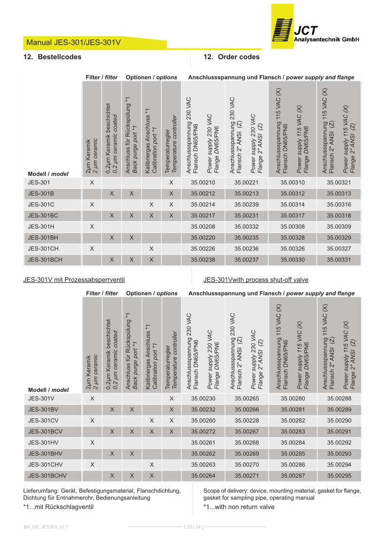
Order codes12.
JES-301Vwith process shut-off valve
Scope of delivery: device, mounting material, gasket for flange,gasket for sampling pipe, operating manual *1...with non return valve
Manual JES-301/JES-301V
Bestellcodes12.
JES-301V mit Prozessabsperrventil
Lieferumfang: Gerät, Befestigungsmaterial, Flanschdichtung,Dichtung für Entnahmerohr, Bedienungsanleitung*1...mit Rückschlagventil
BA_DE_JES301_v2.1 ––––––––––––––– [ 25 / 34 ] –––––––––––––––––
Filter / filter Optionen / options Anschlussspannung und Flansch / power supply and flange
Modell / model 2µm
ker
amik
2
µm c
eram
ic
0,2µ
m k
eram
ik b
esch
icht
et0,
2 µm
cer
amic
coa
ted
Ans
chlu
ss fü
r Rüc
kspü
lung
*1
Bac
k pu
rge
port
*1
kal
ibrie
rgas
Ans
chlu
ss *
1C
alib
ratio
n po
rt *1
Tem
pera
turr
egle
rTe
mpe
ratu
re c
ontro
ller
Ans
chlu
sssp
annu
ng 2
30 V
Ac
Flan
sch
DN
65/P
N6
Pow
er s
uppl
y 23
0 VA
CFl
ange
DN
65/P
N6
Ans
chlu
sssp
annu
ng 2
30 V
Ac
Flan
sch
2" A
NS
I (Z
)
Pow
er s
uppl
y 23
0 VA
CFl
ange
2" A
NS
I (Z
)
Ans
chlu
sssp
annu
ng 1
15 V
Ac
(X)
Flan
sch
DN
65/P
N6
Pow
er s
uppl
y 11
5 VA
C (X
)Fl
ange
DN
65/P
N6
Ans
chlu
sssp
annu
ng 1
15 V
Ac
(X)
Flan
sch
2" A
NS
I (Z
)
Pow
er s
uppl
y 11
5 VA
C (X
)Fl
ange
2" A
NS
I (Z
)
JES-301 X X 35.00210 35.00221 35.00310 35.00321
JES-301B X X X 35.00212 35.00213 35.00312 35.00313
JES-301c X X X 35.00214 35.00239 35.00314 35.00316
JES-301Bc X X X X 35.00217 35.00231 35.00317 35.00318
JES-301h X 35.00208 35.00332 35.00308 35.00309
JES-301Bh X X 35.00220 35.00235 35.00328 35.00329
JES-301ch X X 35.00226 35.00236 35.00326 35.00327
JES-301Bch X X X 35.00238 35.00237 35.00330 35.00331
Filter / filter Optionen / options Anschlussspannung und Flansch / power supply and flange
Modell / model 2µm
ker
amik
2
µm c
eram
ic
0,2µ
m k
eram
ik b
esch
icht
et0,
2 µm
cer
amic
coa
ted
Ans
chlu
ss fü
r Rüc
kspü
lung
*1
Bac
k pu
rge
port
*1
kal
ibrie
rgas
Ans
chlu
ss *
1C
alib
ratio
n po
rt *1
Tem
pera
turr
egle
rTe
mpe
ratu
re c
ontro
ller
Ans
chlu
sssp
annu
ng 2
30 V
Ac
Flan
sch
DN
65/P
N6
Pow
er s
uppl
y 23
0 VA
CFl
ange
DN
65/P
N6
Ans
chlu
sssp
annu
ng 2
30 V
Ac
Flan
sch
2" A
NS
I (Z
)
Pow
er s
uppl
y 23
0 VA
CFl
ange
2" A
NS
I (Z
)
Ans
chlu
sssp
annu
ng 1
15 V
Ac
(X)
Flan
sch
DN
65/P
N6
Pow
er s
uppl
y 11
5 VA
C (X
)Fl
ange
DN
65/P
N6
Ans
chlu
sssp
annu
ng 1
15 V
Ac
(X)
Flan
sch
2" A
NS
I (Z
)
Pow
er s
uppl
y 11
5 VA
C (X
)Fl
ange
2" A
NS
I (Z
)
JES-301V X X 35.00230 35.00265 35.00280 35.00288
JES-301BV X X X 35.00232 35.00266 35.00281 35.00289
JES-301cV X X X 35.00260 35.00228 35.00282 35.00290
JES-301BcV X X X X 35.00272 35.00267 35.00283 35.00291
JES-301hV X 35.00261 35.00268 35.00284 35.00292
JES-301BhV X X 35.00262 35.00269 35.00285 35.00293
JES-301chV X X 35.00263 35.00270 35.00286 35.00294
JES-301BchV X X X 35.00264 35.00271 35.00287 35.00295
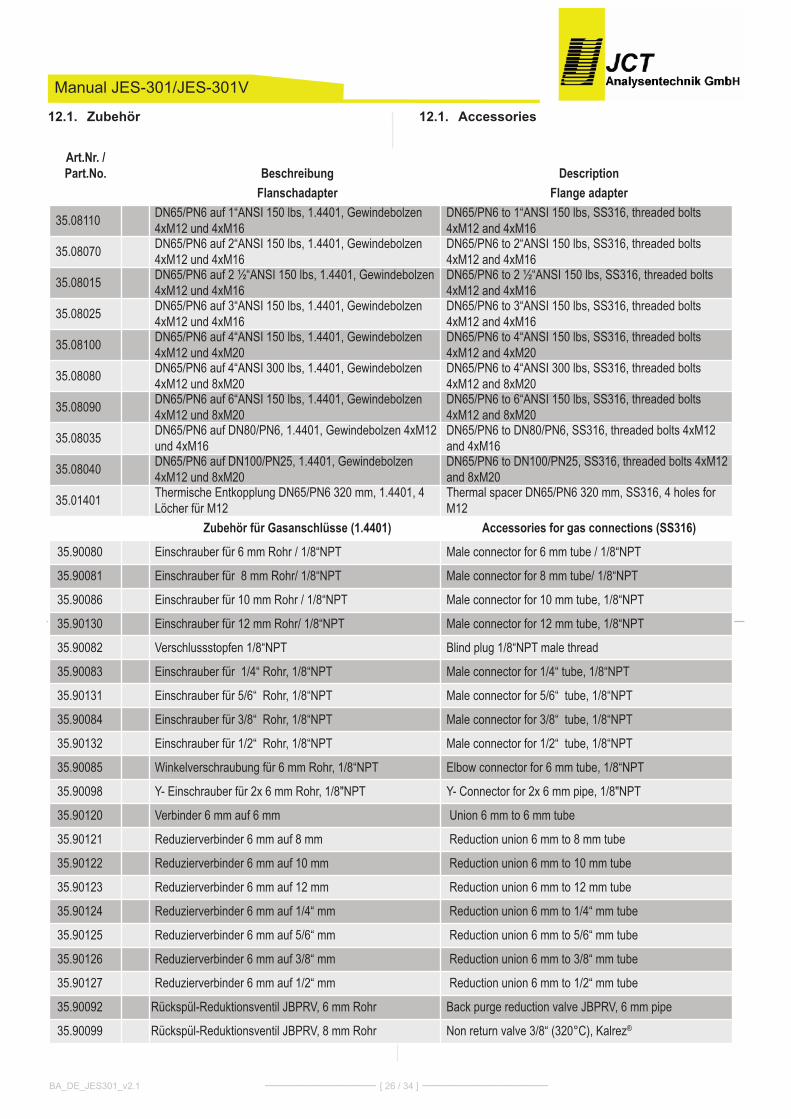
Accessories12.1.
Manual JES-301/JES-301V
Zubehör12.1.
BA_DE_JES301_v2.1 ––––––––––––––– [ 26 / 34 ] –––––––––––––––––
Art.Nr. /Part.No. Beschreibung Description
Flanschadapter Flange adapter
35.08110 DN65/PN6 auf 1“ANSI 150 lbs, 1.4401, Gewindebolzen4xM12 und 4xM16
DN65/PN6 to 1“ANSI 150 lbs, SS316, threaded bolts4xM12 and 4xM16
35.08070 DN65/PN6 auf 2“ANSI 150 lbs, 1.4401, Gewindebolzen4xM12 und 4xM16
DN65/PN6 to 2“ANSI 150 lbs, SS316, threaded bolts4xM12 and 4xM16
35.08015 DN65/PN6 auf 2 ½“ANSI 150 lbs, 1.4401, Gewindebolzen4xM12 und 4xM16
DN65/PN6 to 2 ½“ANSI 150 lbs, SS316, threaded bolts4xM12 and 4xM16
35.08025 DN65/PN6 auf 3“ANSI 150 lbs, 1.4401, Gewindebolzen4xM12 und 4xM16
DN65/PN6 to 3“ANSI 150 lbs, SS316, threaded bolts4xM12 and 4xM16
35.08100 DN65/PN6 auf 4“ANSI 150 lbs, 1.4401, Gewindebolzen4xM12 und 4xM20
DN65/PN6 to 4“ANSI 150 lbs, SS316, threaded bolts4xM12 and 4xM20
35.08080 DN65/PN6 auf 4“ANSI 300 lbs, 1.4401, Gewindebolzen4xM12 und 8xM20
DN65/PN6 to 4“ANSI 300 lbs, SS316, threaded bolts4xM12 and 8xM20
35.08090 DN65/PN6 auf 6“ANSI 150 lbs, 1.4401, Gewindebolzen4xM12 und 8xM20
DN65/PN6 to 6“ANSI 150 lbs, SS316, threaded bolts4xM12 and 8xM20
35.08035 DN65/PN6 auf DN80/PN6, 1.4401, Gewindebolzen 4xM12und 4xM16
DN65/PN6 to DN80/PN6, SS316, threaded bolts 4xM12and 4xM16
35.08040 DN65/PN6 auf DN100/PN25, 1.4401, Gewindebolzen4xM12 und 8xM20
DN65/PN6 to DN100/PN25, SS316, threaded bolts 4xM12and 8xM20
35.01401 Thermische Entkopplung DN65/PN6 320 mm, 1.4401, 4Löcher für M12
Thermal spacer DN65/PN6 320 mm, SS316, 4 holes forM12
Zubehör für Gasanschlüsse (1.4401) Accessories for gas connections (SS316)
35.90080 Einschrauber für 6 mm Rohr / 1/8“NPT Male connector for 6 mm tube / 1/8“NPT
35.90081 Einschrauber für 8 mm Rohr/ 1/8“NPT Male connector for 8 mm tube/ 1/8“NPT
35.90086 Einschrauber für 10 mm Rohr / 1/8“NPT Male connector for 10 mm tube, 1/8“NPT
35.90130 Einschrauber für 12 mm Rohr/ 1/8“NPT Male connector for 12 mm tube, 1/8“NPT
35.90082 Verschlussstopfen 1/8“NPT Blind plug 1/8“NPT male thread
35.90083 Einschrauber für 1/4“ Rohr, 1/8“NPT Male connector for 1/4“ tube, 1/8“NPT
35.90131 Einschrauber für 5/6“ Rohr, 1/8“NPT Male connector for 5/6“ tube, 1/8“NPT
35.90084 Einschrauber für 3/8“ Rohr, 1/8“NPT Male connector for 3/8“ tube, 1/8“NPT
35.90132 Einschrauber für 1/2“ Rohr, 1/8“NPT Male connector for 1/2“ tube, 1/8“NPT
35.90085 Winkelverschraubung für 6 mm Rohr, 1/8“NPT Elbow connector for 6 mm tube, 1/8“NPT
35.90098 Y- Einschrauber für 2x 6 mm Rohr, 1/8"NPT Y- Connector for 2x 6 mm pipe, 1/8"NPT
35.90120 Verbinder 6 mm auf 6 mm Union 6 mm to 6 mm tube
35.90121 Reduzierverbinder 6 mm auf 8 mm Reduction union 6 mm to 8 mm tube
35.90122 Reduzierverbinder 6 mm auf 10 mm Reduction union 6 mm to 10 mm tube
35.90123 Reduzierverbinder 6 mm auf 12 mm Reduction union 6 mm to 12 mm tube
35.90124 Reduzierverbinder 6 mm auf 1/4“ mm Reduction union 6 mm to 1/4“ mm tube
35.90125 Reduzierverbinder 6 mm auf 5/6“ mm Reduction union 6 mm to 5/6“ mm tube
35.90126 Reduzierverbinder 6 mm auf 3/8“ mm Reduction union 6 mm to 3/8“ mm tube
35.90127 Reduzierverbinder 6 mm auf 1/2“ mm Reduction union 6 mm to 1/2“ mm tube
35.90092 Rückspül-Reduktionsventil JBPRV, 6 mm Rohr Back purge reduction valve JBPRV, 6 mm pipe
35.90099 Rückspül-Reduktionsventil JBPRV, 8 mm Rohr Non return valve 3/8“ (320°C), Kalrez®
Manual JES-301/JES-301V
BA_DE_JES301_v2.1 ––––––––––––––– [ 27 / 34 ] –––––––––––––––––
Art.Nr. /Part.No. Beschreibung Description
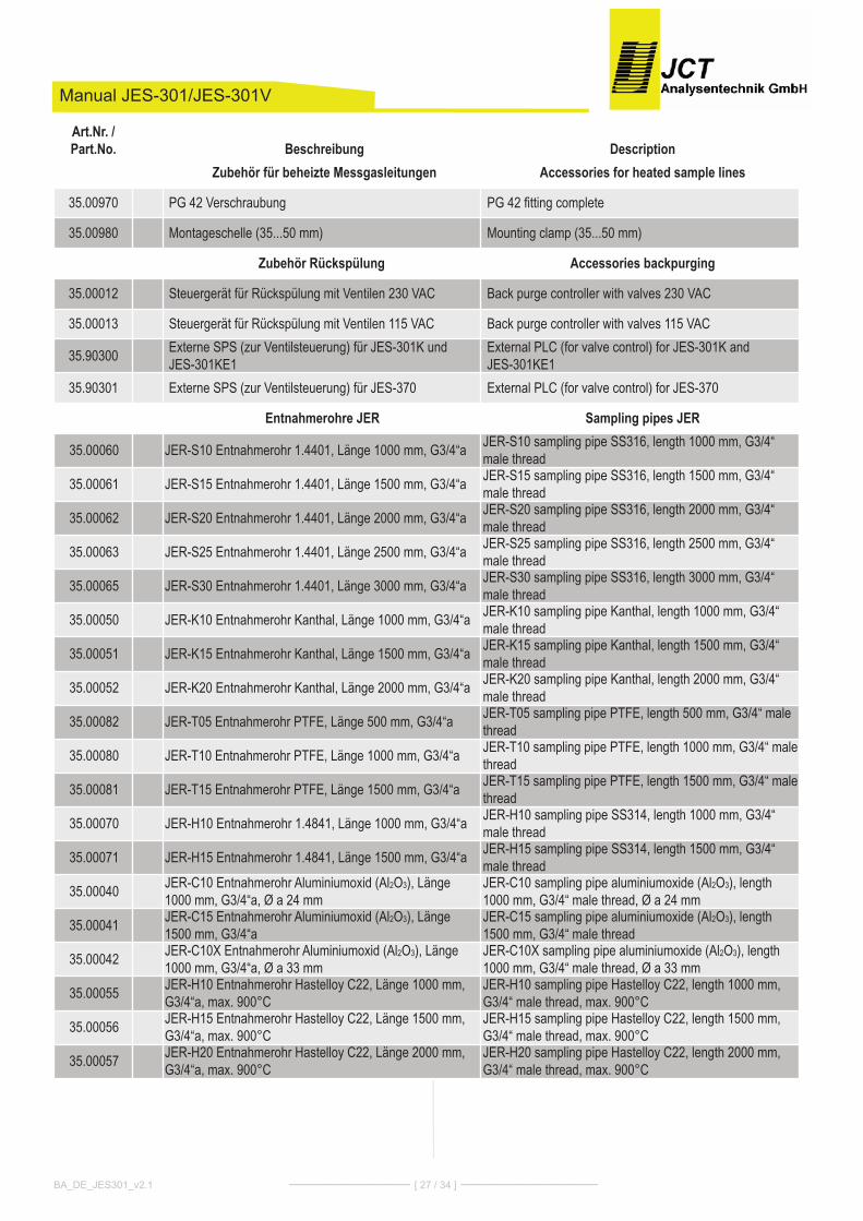
Zubehör für beheizte Messgasleitungen Accessories for heated sample lines
35.00970 PG 42 Verschraubung PG 42 fitting complete
35.00980 Montageschelle (35...50 mm) Mounting clamp (35...50 mm)
Zubehör Rückspülung Accessories backpurging
35.00012 Steuergerät für Rückspülung mit Ventilen 230 VAC Back purge controller with valves 230 VAC
35.00013 Steuergerät für Rückspülung mit Ventilen 115 VAC Back purge controller with valves 115 VAC
35.90300 Externe SPS (zur Ventilsteuerung) für JES-301K und JES-301KE1
External PLC (for valve control) for JES-301K and JES-301KE1
35.90301 Externe SPS (zur Ventilsteuerung) für JES-370 External PLC (for valve control) for JES-370
Entnahmerohre JER Sampling pipes JER
35.00060 JER-S10 Entnahmerohr 1.4401, Länge 1000 mm, G3/4“a JER-S10 sampling pipe SS316, length 1000 mm, G3/4“male thread
35.00061 JER-S15 Entnahmerohr 1.4401, Länge 1500 mm, G3/4“a JER-S15 sampling pipe SS316, length 1500 mm, G3/4“male thread
35.00062 JER-S20 Entnahmerohr 1.4401, Länge 2000 mm, G3/4“a JER-S20 sampling pipe SS316, length 2000 mm, G3/4“male thread
35.00063 JER-S25 Entnahmerohr 1.4401, Länge 2500 mm, G3/4“a JER-S25 sampling pipe SS316, length 2500 mm, G3/4“male thread
35.00065 JER-S30 Entnahmerohr 1.4401, Länge 3000 mm, G3/4“a JER-S30 sampling pipe SS316, length 3000 mm, G3/4“male thread
35.00050 JER-K10 Entnahmerohr Kanthal, Länge 1000 mm, G3/4“a JER-K10 sampling pipe Kanthal, length 1000 mm, G3/4“male thread
35.00051 JER-K15 Entnahmerohr Kanthal, Länge 1500 mm, G3/4“a JER-K15 sampling pipe Kanthal, length 1500 mm, G3/4“male thread
35.00052 JER-K20 Entnahmerohr Kanthal, Länge 2000 mm, G3/4“a JER-K20 sampling pipe Kanthal, length 2000 mm, G3/4“male thread
35.00082 JER-T05 Entnahmerohr PTFE, Länge 500 mm, G3/4“a JER-T05 sampling pipe PTFE, length 500 mm, G3/4“ malethread
35.00080 JER-T10 Entnahmerohr PTFE, Länge 1000 mm, G3/4“a JER-T10 sampling pipe PTFE, length 1000 mm, G3/4“ malethread
35.00081 JER-T15 Entnahmerohr PTFE, Länge 1500 mm, G3/4“a JER-T15 sampling pipe PTFE, length 1500 mm, G3/4“ malethread
35.00070 JER-H10 Entnahmerohr 1.4841, Länge 1000 mm, G3/4“a JER-H10 sampling pipe SS314, length 1000 mm, G3/4“male thread
35.00071 JER-H15 Entnahmerohr 1.4841, Länge 1500 mm, G3/4“a JER-H15 sampling pipe SS314, length 1500 mm, G3/4“male thread
35.00040 JER-C10 Entnahmerohr Aluminiumoxid (Al2O3), Länge1000 mm, G3/4“a, Ø a 24 mm
JER-C10 sampling pipe aluminiumoxide (Al2O3), length1000 mm, G3/4“ male thread, Ø a 24 mm
35.00041 JER-C15 Entnahmerohr Aluminiumoxid (Al2O3), Länge1500 mm, G3/4“a
JER-C15 sampling pipe aluminiumoxide (Al2O3), length1500 mm, G3/4“ male thread
35.00042 JER-C10X Entnahmerohr Aluminiumoxid (Al2O3), Länge1000 mm, G3/4“a, Ø a 33 mm
JER-C10X sampling pipe aluminiumoxide (Al2O3), length1000 mm, G3/4“ male thread, Ø a 33 mm
35.00055 JER-H10 Entnahmerohr Hastelloy C22, Länge 1000 mm,G3/4“a, max. 900°C
JER-H10 sampling pipe Hastelloy C22, length 1000 mm,G3/4“ male thread, max. 900°C
35.00056 JER-H15 Entnahmerohr Hastelloy C22, Länge 1500 mm,G3/4“a, max. 900°C
JER-H15 sampling pipe Hastelloy C22, length 1500 mm,G3/4“ male thread, max. 900°C
35.00057 JER-H20 Entnahmerohr Hastelloy C22, Länge 2000 mm,G3/4“a, max. 900°C
JER-H20 sampling pipe Hastelloy C22, length 2000 mm,G3/4“ male thread, max. 900°C
Manual JES-301/JES-301V
BA_DE_JES301_v2.1 ––––––––––––––– [ 28 / 34 ] –––––––––––––––––
Art.Nr. /Part.No. Beschreibung Description
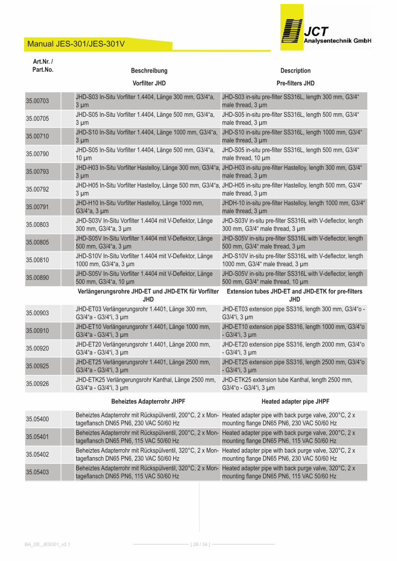
Vorfilter JHD Pre-filters JHD
35.00703 JHD-S03 In-Situ Vorfilter 1.4404, Länge 300 mm, G3/4“a, 3 µm
JHD-S03 in-situ pre-filter SS316L, length 300 mm, G3/4“male thread, 3 µm
35.00705 JHD-S05 In-Situ Vorfilter 1.4404, Länge 500 mm, G3/4“a, 3 µm
JHD-S05 in-situ pre-filter SS316L, length 500 mm, G3/4“male thread, 3 µm
35.00710 JHD-S10 In-Situ Vorfilter 1.4404, Länge 1000 mm, G3/4“a,3 µm
JHD-S10 in-situ pre-filter SS316L, length 1000 mm, G3/4“male thread, 3 µm
35.00790 JHD-S05 In-Situ Vorfilter 1.4404, Länge 500 mm, G3/4“a,10 µm
JHD-S05 in-situ pre-filter SS316L, length 500 mm, G3/4“male thread, 10 µm
35.00793 JHD-H03 In-Situ Vorfilter Hastelloy, Länge 300 mm, G3/4“a,3 µm
JHD-H03 in-situ pre-filter Hastelloy, length 300 mm, G3/4“male thread, 3 µm
35.00792 JHD-H05 In-Situ Vorfilter Hastelloy, Länge 500 mm, G3/4“a,3 µm
JHD-H05 in-situ pre-filter Hastelloy, length 500 mm, G3/4“male thread, 3 µm
35.00791 JHD-H10 In-Situ Vorfilter Hastelloy, Länge 1000 mm,G3/4“a, 3 µm
JHDH-10 in-situ pre-filter Hastelloy, length 1000 mm, G3/4“male thread, 3 µm
35.00803 JHD-S03V In-Situ Vorfilter 1.4404 mit V-Deflektor, Länge300 mm, G3/4“a, 3 µm
JHD-S03V in-situ pre-filter SS316L with V-deflector, length300 mm, G3/4“ male thread, 3 µm
35.00805 JHD-S05V In-Situ Vorfilter 1.4404 mit V-Deflektor, Länge500 mm, G3/4“a, 3 µm
JHD-S05V in-situ pre-filter SS316L with V-deflector, length500 mm, G3/4“ male thread, 3 µm
35.00810 JHD-S10V In-Situ Vorfilter 1.4404 mit V-Deflektor, Länge1000 mm, G3/4“a, 3 µm
JHD-S10V in-situ pre-filter SS316L with V-deflector, length1000 mm, G3/4“ male thread, 3 µm
35.00890 JHD-S05V In-Situ Vorfilter 1.4404 mit V-Deflektor, Länge500 mm, G3/4“a, 10 µm
JHD-S05V in-situ pre-filter SS316L with V-deflector, length500 mm, G3/4“ male thread, 10 µm
Verlängerungsrohre JHD-ET und JHD-ETK für VorfilterJHD
Extension tubes JHD-ET and JHD-ETK for pre-filtersJHD
35.00903 JHD-ET03 Verlängerungsrohr 1.4401, Länge 300 mm,G3/4“a - G3/4“i, 3 µm
JHD-ET03 extension pipe SS316, length 300 mm, G3/4“o -G3/4“i, 3 µm
35.00910 JHD-ET10 Verlängerungsrohr 1.4401, Länge 1000 mm,G3/4“a - G3/4“i, 3 µm
JHD-ET10 extension pipe SS316, length 1000 mm, G3/4“o- G3/4“i, 3 µm
35.00920 JHD-ET20 Verlängerungsrohr 1.4401, Länge 2000 mm,G3/4“a - G3/4“i, 3 µm
JHD-ET20 extension pipe SS316, length 2000 mm, G3/4“o- G3/4“i, 3 µm
35.00925 JHD-ET25 Verlängerungsrohr 1.4401, Länge 2500 mm,G3/4“a - G3/4“i, 3 µm
JHD-ET25 extension pipe SS316, length 2500 mm, G3/4“o- G3/4“i, 3 µm
35.00926 JHD-ETK25 Verlängerungsrohr Kanthal, Länge 2500 mm,G3/4“a - G3/4“i, 3 µm
JHD-ETK25 extension tube Kanthal, length 2500 mm,G3/4“o - G3/4“i, 3 µm
Beheiztes Adapterrohr JHPF Heated adapter pipe JHPF
35.05400 Beheiztes Adapterrohr mit Rückspülventil, 200°C, 2 x Mon-tageflansch DN65 PN6, 230 VAC 50/60 Hz
Heated adapter pipe with back purge valve, 200°C, 2 xmounting flange DN65 PN6, 230 VAC 50/60 Hz
35.05401 Beheiztes Adapterrohr mit Rückspülventil, 200°C, 2 x Mon-tageflansch DN65 PN6, 115 VAC 50/60 Hz
Heated adapter pipe with back purge valve, 200°C, 2 xmounting flange DN65 PN6, 115 VAC 50/60 Hz
35.05402 Beheiztes Adapterrohr mit Rückspülventil, 320°C, 2 x Mon-tageflansch DN65 PN6, 230 VAC 50/60 Hz
Heated adapter pipe with back purge valve, 320°C, 2 xmounting flange DN65 PN6, 230 VAC 50/60 Hz
35.05403 Beheiztes Adapterrohr mit Rückspülventil, 320°C, 2 x Mon-tageflansch DN65 PN6, 115 VAC 50/60 Hz
Heated adapter pipe with back purge valve, 320°C, 2 xmounting flange DN65 PN6, 115 VAC 50/60 Hz
Spare parts12.2.
*1...position numbers relate to section drawing on page 4 and 5
Manual JES-301/JES-301V
Ersatzteile12.2.
*1...Positionsnummern beziehen sich auf Schnitt-zeichnung auf Seite 4 und 5
BA_DE_JES301_v2.1 ––––––––––––––– [ 29 / 34 ] –––––––––––––––––
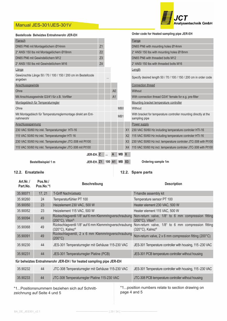
Bestellcode Beheiztes Entnahmerohr JER-EH Order code for Heated sampling pipe JER-EH
Flansch FlangeDN65 PN6 mit Montagelöchern Ø14mm Z1 DN65 PN6 with mounting holes Ø14mm2“ ANSI 150 lbs mit Montagelöchern Ø18mm Z2 2“ ANSI 150 lbs with mounting holes Ø18mmDN65 PN6 mit Gewindelöchern M12 Z3 DN65 PN6 with threaded bolts M122“ ANSI 150 lbs mit Gewindelöchern M16 Z4 2“ ANSI 150 lbs with threaded bolts M16Länge LengthGewünschte Länge 50 / 70 / 100 / 150 / 200 cm im Bestellcodeangeben ... Specify desired length 50 / 70 / 100 / 150 / 200 cm in order code
Anschlussgewinde Connection threadOhne A0 Without Mit Anschlussgewinde G3/4“i für z.B. Vorfilter A1 With connection thread G3/4“ female for e.g. pre-filterMontageblech für Temperaturregler Mounting bracket temperature controllerOhne MB0 WithoutMit Montageblech für Temperaturreglermontage direkt am Ent-nahmerohr MB1 With bracket for temperature controller mounting directly at the
sampling pipeAnschlussspannung Power supply230 VAC 50/60 Hz inkl. Temperaturregler HTI-16 X1 230 VAC 50/60 Hz including temperature controler HTI-16115 VAC 50/60 Hz inkl. Temperaturregler HTI 16 X2 115 VAC 50/60 Hz including temperature controler HTI-16230 VAC 50/60 Hz inkl. Temperaturregler JTC-308 mit Pt100 X3 230 VAC 50/60 Hz incl. temperature controler JTC-308 with Pt100115 VAC 50/60 Hz inkl. Temperaturregler JTC-308 mit Pt100 X4 115 VAC 50/60 Hz incl. temperature controler JTC-308 with Pt100
JER-EH. Z ... A MB X
Bestellbeispiel 1 m JER-EH. Z1 100 A1 MB X3 Ordering sample 1m
Art.Nr. /Part.No.
Pos.Nr./Pos.No.*1 Beschreibung Description
35.90071 17, 21 T-Griff Nachrüstsatz T-handle assembly kit35.90260 24 Temperaturfühler PT 100 Temperature sensor PT 10035.90050 23 Heizelement 230 VAC, 500 W Heater element 230 VAC, 500 W35.90052 23 Heizelement 115 VAC, 500 W Heater element 115 VAC, 500 W
35.90094 49 Rückschlagventil 1/8“ auf 6 mm Klemmringverschraubung(200°C), Viton®,
Non-return valve, 1/8“ to 6 mm compression fitting(200°C), Viton®,
35.90068 49 Rückschlagventil 1/8“ auf 6 mm Klemmringverschraubung(320°C), Kalrez®
Non-return valve, 1/8“ to 6 mm compression fitting(320°C), Kalrez®
35.90091 49 Rückschlagventil, 2 x 6 mm Klemmringverschraubung(200°C) Non-return valve, 2 x 6 mm compression fitting (200°C)
35.90230 44 JES-301 Temperaturregler mit Gehäuse 115-230 VAC JES-301 Temperature controller with housing, 115 -230 VAC
35.90231 44 JES-301 Temperaturregler Platine (PCB) JES-301 PCB temperature controller without housing
für beheiztes Entnahmerohr JER-EH / for heated sampling pipe JER-EH
35.90232 44 JTC-308 Temperaturregler mit Gehäuse 115-230 VAC JES-301 Temperature controller with housing, 115 -230 VAC
35.90233 44 JTC-308 Temperaturregler Platine 115-230 VAC JTC-308 PCB temperature controller without housing
Manual JES-301
BA_DE_JES301_v2.1 ––––––––––––––– [ 30 / 34 ] –––––––––––––––––
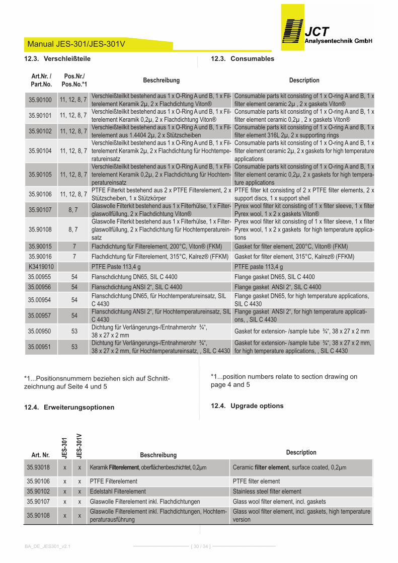
Consumables12.3.
*1...position numbers relate to section drawing on page 4 and 5
Upgrade options12.4.
Manual JES-301/JES-301V
Verschleißteile12.3.
*1...Positionsnummern beziehen sich auf Schnitt-zeichnung auf Seite 4 und 5
Erweiterungsoptionen12.4.
Art.Nr. /Part.No.
Pos.Nr./Pos.No.*1 Beschreibung Description
35.90100 11, 12, 8, 7 Verschleißteilkit bestehend aus 1 x O-Ring A und B, 1 x Fil-terelement Keramik 2µ, 2 x Flachdichtung Viton®
Consumable parts kit consisting of 1 x O-ring A and B, 1 xfilter element ceramic 2µ , 2 x gaskets Viton®
35.90101 11, 12, 8, 7 Verschleißteilkit bestehend aus 1 x O-Ring A und B, 1 x Fil-terelement Keramik 0,2µ, 2 x Flachdichtung Viton®
Consumable parts kit consisting of 1 x O-ring A and B, 1 xfilter element ceramic 0,2µ , 2 x gaskets Viton®
35.90102 11, 12, 8, 7 Verschleißteilkit bestehend aus 1 x O-Ring A und B, 1 x Fil-terelement aus 1.4404 2µ, 2 x Stützscheiben
Consumable parts kit consisting of 1 x O-ring A and B, 1 xfilter element 316L 2µ, 2 x supporting rings
35.90104 11, 12, 8, 7Verschleißteilkit bestehend aus 1 x O-Ring A und B, 1 x Fil-terelement Keramik 2µ, 2 x Flachdichtung für Hochtempe-ratureinsatz
Consumable parts kit consisting of 1 x O-ring A and B, 1 xfilter element ceramic 2µ, 2 x gaskets for high temperatureapplications
35.90105 11, 12, 8, 7Verschleißteilkit bestehend aus 1 x O-Ring A und B, 1 x Fil-terelement Keramik 0,2µ, 2 x Flachdichtung für Hochtem-peratureinsatz
Consumable parts kit consisting of 1 x O-ring A and B, 1 xfilter element ceramic 0,2µ, 2 x gaskets for high tempera-ture applications
35.90106 11, 12, 8, 7 PTFE Filterkit bestehend aus 2 x PTFE Filterelement, 2 xStützscheiben, 1 x Stützkörper
PTFE filter kit consisting of 2 x PTFE filter elements, 2 xsupport discs, 1 x support shell
35.90107 8, 7 Glaswolle Filterkit bestehend aus 1 x Filterhülse, 1 x Filter-glaswollfüllung, 2 x Flachdichtung Viton®
Pyrex wool filter kit consisting of 1 x filter sleeve, 1 x filterPyrex wool, 1 x 2 x gaskets Viton®
35.90108 8, 7Glaswolle Filterkit bestehend aus 1 x Filterhülse, 1 x Filter-glaswollfüllung, 2 x Flachdichtung für Hochtemperaturein-satz
Pyrex wool filter kit consisting of 1 x filter sleeve, 1 x filterPyrex wool, 1 x 2 x gaskets for high temperature applica-tions
35.90015 7 Flachdichtung für Filterelement, 200°C, Viton® (FKM) Gasket for filter element, 200°C, Viton® (FKM)35.90016 7 Flachdichtung für Filterelement, 315°C, Kalrez® (FFKM) Gasket for filter element, 315°C, Kalrez® (FFKM)K3419010 PTFE Paste 113,4 g PTFE paste 113,4 g35.00955 54 Flanschdichtung DN65, SIL C 4400 Flange gasket DN65, SIL C 440035.00956 54 Flanschdichtung ANSI 2“, SIL C 4400 Flange gasket ANSI 2“, SIL C 4400
35.00954 54 Flanschdichtung DN65, für Hochtemperatureinsatz, SILC 4430
Flange gasket DN65, for high temperature applications,SIL C 4430
35.00957 54 Flanschdichtung ANSI 2“, für Hochtemperatureinsatz, SILC 4430
Flange gasket ANSI 2“, for high temperature applicati-ons, , SIL C 4430
35.00950 53 Dichtung für Verlängerungs-/Entnahmerohr ¾“, 38 x 27 x 2 mm Gasket for extension- /sample tube ¾“, 38 x 27 x 2 mm
35.00951 53 Dichtung für Verlängerungs-/Entnahmerohr ¾“, 38 x 27 x 2 mm, für Hochtemperatureinsatz, , SIL C 4430
Gasket for extension- /sample tube ¾“, 38 x 27 x 2 mm,for high temperature applications, , SIL C 4430
Art. Nr. JES-30
1
JES-30
1V
Beschreibung Description
35.93018 x x Keramik Filterelement, oberflächenbeschichtet, 0,2µm Ceramic filter element, surface coated, 0,2µm
35.90106 x x PTFE Filterelement PTFE filter element35.90102 x x Edelstahl Filterelement Stainless steel filter element35.90107 x x Glaswolle Filterelement inkl. Flachdichtungen Glass wool filter element, incl. gaskets
35.90108 x x Glaswolle Filterelement inkl. Flachdichtungen, Hochtem-peraturausführung
Glass wool filter element, incl. gaskets, high temperatureversion
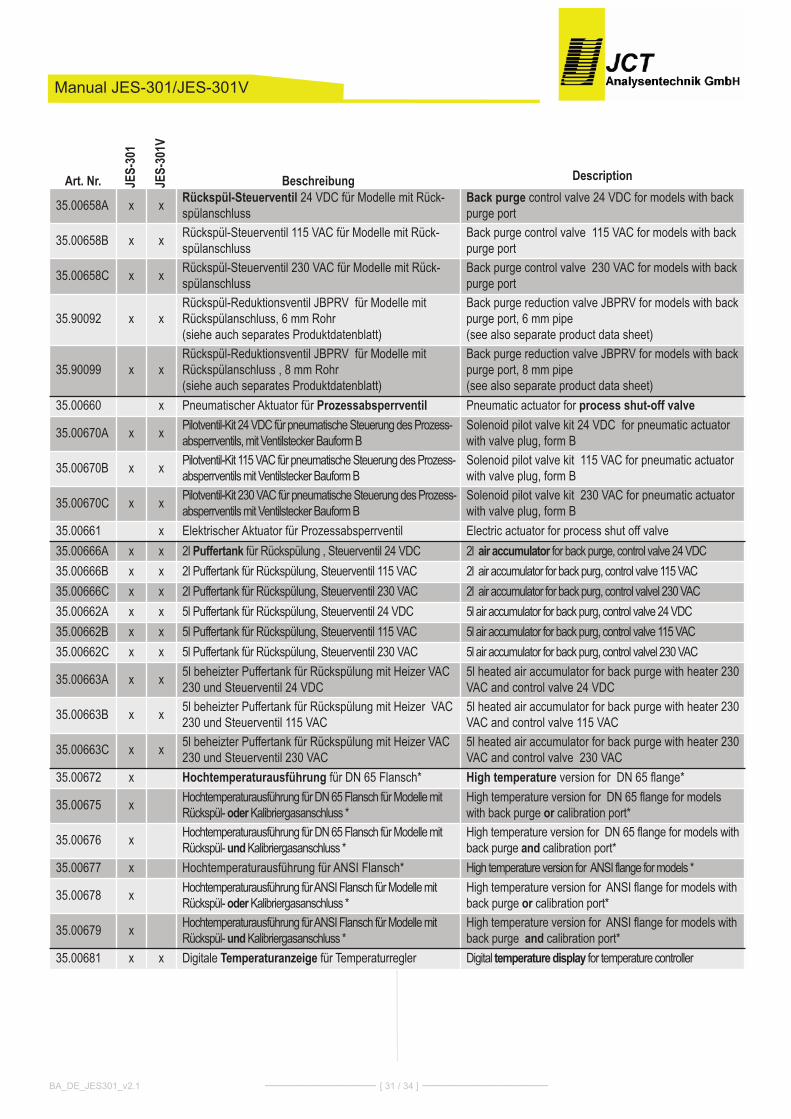
Manual JES-301/JES-301V
BA_DE_JES301_v2.1 ––––––––––––––– [ 31 / 34 ] –––––––––––––––––
Art. Nr. JES-30
1
JES-30
1VBeschreibung Description
35.00658A x x Rückspül-Steuerventil 24 VDC für Modelle mit Rück-spülanschluss
Back purge control valve 24 VDC for models with backpurge port
35.00658B x x Rückspül-Steuerventil 115 VAC für Modelle mit Rück-spülanschluss
Back purge control valve 115 VAC for models with backpurge port
35.00658C x x Rückspül-Steuerventil 230 VAC für Modelle mit Rück-spülanschluss
Back purge control valve 230 VAC for models with backpurge port
35.90092 x xRückspül-Reduktionsventil JBPRV für Modelle mitRückspülanschluss, 6 mm Rohr(siehe auch separates Produktdatenblatt)
Back purge reduction valve JBPRV for models with backpurge port, 6 mm pipe (see also separate product data sheet)
35.90099 x xRückspül-Reduktionsventil JBPRV für Modelle mitRückspülanschluss , 8 mm Rohr(siehe auch separates Produktdatenblatt)
Back purge reduction valve JBPRV for models with backpurge port, 8 mm pipe (see also separate product data sheet)
35.00660 x Pneumatischer Aktuator für Prozessabsperrventil Pneumatic actuator for process shut-off valve
35.00670A x x Pilotventil-Kit 24 VDC für pneumatische Steuerung des Prozess-absperrventils, mit Ventilstecker Bauform B
Solenoid pilot valve kit 24 VDC for pneumatic actuatorwith valve plug, form B
35.00670B x x Pilotventil-Kit 115 VAC für pneumatische Steuerung des Prozess-absperrventils mit Ventilstecker Bauform B
Solenoid pilot valve kit 115 VAC for pneumatic actuatorwith valve plug, form B
35.00670C x x Pilotventil-Kit 230 VAC für pneumatische Steuerung des Prozess-absperrventils mit Ventilstecker Bauform B
Solenoid pilot valve kit 230 VAC for pneumatic actuatorwith valve plug, form B
35.00661 x Elektrischer Aktuator für Prozessabsperrventil Electric actuator for process shut off valve35.00666A x x 2l Puffertank für Rückspülung , Steuerventil 24 VDC 2l air accumulator for back purge, control valve 24 VDC35.00666B x x 2l Puffertank für Rückspülung, Steuerventil 115 VAC 2l air accumulator for back purg, control valve 115 VAC35.00666C x x 2l Puffertank für Rückspülung, Steuerventil 230 VAC 2l air accumulator for back purg, control valvel 230 VAC35.00662A x x 5l Puffertank für Rückspülung, Steuerventil 24 VDC 5l air accumulator for back purg, control valve 24 VDC35.00662B x x 5l Puffertank für Rückspülung, Steuerventil 115 VAC 5l air accumulator for back purg, control valve 115 VAC35.00662C x x 5l Puffertank für Rückspülung, Steuerventil 230 VAC 5l air accumulator for back purg, control valvel 230 VAC
35.00663A x x 5l beheizter Puffertank für Rückspülung mit Heizer VAC230 und Steuerventil 24 VDC
5l heated air accumulator for back purge with heater 230VAC and control valve 24 VDC
35.00663B x x 5l beheizter Puffertank für Rückspülung mit Heizer VAC230 und Steuerventil 115 VAC
5l heated air accumulator for back purge with heater 230VAC and control valve 115 VAC
35.00663C x x 5l beheizter Puffertank für Rückspülung mit Heizer VAC230 und Steuerventil 230 VAC
5l heated air accumulator for back purge with heater 230VAC and control valve 230 VAC
35.00672 x Hochtemperaturausführung für DN 65 Flansch* High temperature version for DN 65 flange*
35.00675 x Hochtemperaturausführung für DN 65 Flansch für Modelle mitRückspül- oderKalibriergasanschluss *
High temperature version for DN 65 flange for modelswith back purge or calibration port*
35.00676 x Hochtemperaturausführung für DN 65 Flansch für Modelle mitRückspül- undKalibriergasanschluss *
High temperature version for DN 65 flange for models withback purge and calibration port*
35.00677 x Hochtemperaturausführung für ANSI Flansch* High temperature version for ANSI flange for models *
35.00678 x Hochtemperaturausführung für ANSI Flansch für Modelle mitRückspül- oderKalibriergasanschluss *
High temperature version for ANSI flange for models withback purge or calibration port*
35.00679 x Hochtemperaturausführung für ANSI Flansch für Modelle mitRückspül- undKalibriergasanschluss *
High temperature version for ANSI flange for models withback purge and calibration port*
35.00681 x x Digitale Temperaturanzeige für Temperaturregler Digital temperature display for temperature controller
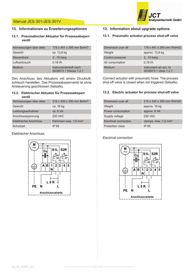
Information about upgrade options13.
Pneumatic actuator process shut-off valve13.1.
connect actuator with pneumatic hose. The processshut-off valve is closed when not triggered (failsafe).
Electric actuator for process shut-off valve13.2.
Electrical connection
1N
MS2RS1L
2 3 4 5
CB
A B
NPE L
Anschlussvariante
L 0 R
Manual JES-301/JES-301V
Informationen zu Erweiterungsoptionen13.
Pneumatischer Aktuator für Prozessabsperr13.1.ventil
Den Anschluss des Aktuators mit einem Druckluft-schlauch herstellen. Das Prozessabsperrventil ist ohneAnsteuerung geschlossen (failsafe).
Elektrischer Aktuator für Prozessabsperr13.2.ventil
Elektrischer Anschluss
1N
MS2RS1L
2 3 4 5
CB
A B
NPE L
Anschlussvariante
L 0 R
BA_DE_JES301_v2.1 ––––––––––––––– [ 32 / 34 ] –––––––––––––––––
Abmessungen über alles 215 x 540 x 395 mm BxhxT
Gewicht ca. 16 kg
Leistungsaufnahme ca. 6 VA
Anschlussspannung 230 VAc
Elektrischer Anschluss klemmen max. 1,5 mm2
Schutzart IP 65
Dimension over all 215 x 540 x 395 mm WxhxD
Weight approx. 16 kg
Power consumption approx. 6 VA
Supply voltage 230 VAc
Electrical connection clamps max. 1,5 mm2
Protection class IP 65
Abmessungen über alles 178 x 461 x 395 mm BxhxT
Gewicht ca. 13,8 kg
Steuerdruck 2...10 barg
Luftverbrauch 0,18 l/h
Medium Instrumentenluft nachISO8573.1 klasse 1.2.1
Dimension over all 178 x 461 x 395 mm WxhxD
Weight approx. 13,8 kg
control pressure 2...10 barg
Air consumption 0,18 l/h
Medium instrument air acc. toISO8573.1 class 1.2.1

Air accumulator13.3.
High temperature version13.4.
Temperature display13.5.To monitor the temperature, the instrument is equippedwith a digital display that shows the actual temperatureor an error if the temperature limits are exceeded.
Display Description...°c Temperature
Error 1 Temperature sensor shorted / open
Error 2 connection to sensor is open
Error 3 Low temperature limit exceeded
Error 4 high temperature limit exceeded
Manual JES-301/JES-301V
Puffertank13.3.
Hochtemperaturausführung13.4.
Digitale Temperaturanzeige13.5.Die aktuelle Temperatur und das Über- bzw. Unterschrei-ten der Grenzwerte wird auf der digitalen Anzeige ange-zeigt.
Anzeige Beschreibung...°c Temperatur
Error 1 Sensorunterbrechung od. kurzschluss
Error 2 Leitung zum Sensor offen
Error 3 Temperaturunterschreitung
Error 4 Temperaturüberschreitung
BA_DE_JES301_v2.1 ––––––––––––––– [ 33 / 34 ] –––––––––––––––––
Volumen 2 l 5 lBetriebsdruck 0,95...17 baraUmgebungstemperatur -10...+100°cMaterial hochlegierter Stahl, rostfreiGewicht ca. 1,7 kg ca.3,6 kgPneumatische Anschlüsse G 1/2“ Inneng. G 1“ Inneng.
Beheizter Puffertank
Abmessungen über alles 596 x 360 x 267 mm BxhxTVolumen 5 lBetriebsdruck 0,95 ... 17 baraMaterial hochlegierter Stahl, rostfreiGewicht ca. 10 kgBefestigung WandmontageBetriebstemperatur 100°c Thermostatgesteuertheizung ca. 200 WAnschlussspannung 230 VAc; 50/60 hzkabeleingang Stromversorgung M Verschraubung 16 x 1,5Anschlussklemmen klemm-bereich
Federzugklemmen 0,08 -2,5 mm2
Pneumatische Anschlüsse G 1” Innengewinde
Volume 2 l 5 lOperating pressure 0,95...17 baraAmbient temperature -10...+100°cMaterial high alloy steel, non-corrosiveWeight approx. 1,7 kg approx. 3,6 kgPneumatic connections G 1/2” female G 1” female
Heated air accumulatorDimension over all 596 x 360 x 267 mm WxhxDVolume 5 lOperating pressure 0,95 ... 17 baraMaterial high alloy steel, non-corrosiveWeight approx. 10kgMounting Wall mountOperating temperature 100°c thermostat controlledheater approx. 200 WSupply voltage 230 VAc; 50/60 hzcable entry supply M - conduit 16 x 1,5connection terminal clam-ping range
Spring type terminal 0,08 - 2,5mm2
Pneumatic connections G 1” female
Temperatureinstellbereich 5...315°c
Werkseinstellung 315°c
Gasberührende Materialien 1.4401, kalrez®, Perlast®
Temperature adjustment range 5...315°c
Factory defaults 315°c
Sample gas wetted parts SS316, kalrez®, Perlast®

Werner heisenberg - Str. 4 / A-2700 Wr. Neustadt / Tel +43 2622 87 201 / Fax +43 2622 87 [email protected] / Firmenbuchgericht: kreisgericht Wr. Neustadt FN 119682 d / UID - Nummer ATU 20559900
Manual JES-301/JES-301V
BA_DE_JES301_v2.1 ––––––––––––––– [ 34 / 34 ] –––––––––––––––––