Katalog 2016 catalogue 2016 · 2017-10-26 · DIN6360AufsteckfräserdornMK 84...
168
Katalog 2016 catalogue 2016 Inhaltsverzeichnis / table of contents / Sommaire Spannzeuge / toolings / Outils de serrage Seite / page DIN 2080 4 - 15 Deckel SK40 S20x2 16 - 19 DIN 69871 20 - 55 MAS BT / JIS 56 - 82 Morsekegel MK / morse taper/ Cônes morses 83 - 87 Drehdorne / Schleifdorne / Broches 88 - 89 Aufsteckhalter/ Porte-outils 87 HS K 90 - 112 Polygonschaft / polygonal shank 113 - 118 Weldonschaft / weldon shank 135 - 136 VD I 119 - 132 Zubehör / accesories / Accessoires Seite / page Zubehör / accesories / Accessoires 133 - 161 Spannzangen + Muttern / collets / Pinces 140 - 148 Anzugsbolzen / pull studs / Tirettes 157 - 161 Schraubstöcke / vices / Etaux 162 - 166 Information Seite / page Exzentrische Bohrung 31 Präz. Bohrfutter / Hydrodehn 75 Die Abbildungen/Maßangaben in Preislisten und Katalogen sind unverbindlich. Technische Änderungen sind vorbehalten Seite 1 KL-TECH s.r.o | www.klte.cz
Transcript of Katalog 2016 catalogue 2016 · 2017-10-26 · DIN6360AufsteckfräserdornMK 84...

Katalog 2016catalogue 2016
Inhaltsverzeichnis / table of contents / Sommaire
Spannzeuge / toolings / Outils de serrage Seite / page
DIN 2080 4 - 15
Deckel SK40 S20x2 16 - 19
DIN 69871 20 - 55
MAS BT / JIS 56 - 82
Morsekegel MK / morse taper/ Cônes morses 83 - 87
Drehdorne / Schleifdorne / Broches 88 - 89
Aufsteckhalter/ Porte-outils 87
H S K 90 - 112
Polygonschaft / polygonal shank 113 - 118
Weldonschaft / weldon shank 135 - 136
V D I 119 - 132
Zubehör / accesories / Accessoires Seite / page
Zubehör / accesories / Accessoires 133 - 161
Spannzangen + Muttern / collets / Pinces 140 - 148
Anzugsbolzen / pull studs / Tirettes 157 - 161
Schraubstöcke / vices / Etaux 162 - 166
Information Seite / page
Exzentrische Bohrung 31
Präz. Bohrfutter / Hydrodehn 75
Die Abbildungen/Maßangaben in Preislisten und Katalogen sind unverbindlich.Technische Änderungen sind vorbehalten
Seite 1
KL-T
ECH
s.r.
o | w
ww
.klte
.cz

Stichwort-Verzeichnis
Bezeichnung Seite Bezeichnung Seite Bezeichnung Seite
Anzugsbolzen 157-161 Gewindeschneidfu. Polygonschaft 113 Rohlinge DIN2080 15Bohrfutteraufnahme DIN69871 38 Gewindeschneidfutter VDI Anfrage Rohlinge DIN69871 55Bohrfutteraufnahme MASBT 70 Gewindeschneidfu. Weldonschaft 136 Rohlinge HSK 112Bohrfutteraufnahme MK 83 Hohlschaftkegel = HSK 90-112 Rohlinge MAS BT 82Bohrfutter DIN2080 8-9 Holzsockel für Spannzangen 153 Rohlinge Polygon 118Bohrfutter DIN69871 38-39 Hydrodehnspannfutter DIN69871 22 Rohlinge VDI 119Bohrfutter HSK 103 Hydrodehnspannfutter HSK 92 S20x2 Sägegewindeaufnahmen 16-19Bohrfutter MAS BT 70-71 Hydrodehnspannfutter MASBT 58 Schleifdorne 89Bohrfutter MK 83 Kantentaster elektr. 153 Schraubstöcke 162-166Bohrfutter S20x2 17 Kegelwischer 156 Schrumpffutter DIN69871 34-37Bohrfutter VDI 131 Kombi-Aufsteck.dorn DIN2080 10 Schrumpffutter HSK 100-102Bohrfutter Zylindrisch 136 Kombi-Aufsteck.dorn DIN69871 40-42 Schrumpffutter MAS BT 66-69Bohrfutter-Kopf 153 Kombi-Aufsteck.dorn HSK 104-105 Schrumpf-Verlängerung 149Deckel S20x2 16-19 Kombi-Aufsteck.dorn MASBT 72-74 Schutzstopfen VDI 132DIN 523 = Drehdorne 88 Kombi-Aufsteck.dorn MK 84 Spannmutter ER Regofix 148DIN 1835B siehe Weldonfutter Kombi-Aufsteck.dorn S20x2 18 Spannmutter OZ Orlieb 141DIN 1835E siehe Whistle-Notch Futter Kraftspannfutter DIN69871 23 Spannschlüssel ER Regofix 148DIN 2080 Aufnahmen 4-15 Kraftspannfutter HSK 93 Spannschlüssel OZ Orlieb 141DIN 2083 = Laufbuchsen 152 Kraftspannfutter MASBT 59 Spannschraube Weldon 133DIN 6355 siehe LangerFräserdorn Kühlmittelnuten-Futter DIN69871 33 Spannzangen ER Regofix 142-146DIN 6357 siehe Messerkopfaufnahme Kühlmittelnuten-Futter HSK 99 Spannzangen OZ Ortlieb 140DIN 6358 siehe Kombi-Aufsteckfräserdorn Kühlmittelnuten-Futter MASBT 65 Spannzangenfutter ER in DIN2080 4DIN 6360 Aufsteckfräserd. 2080 11 Kühlmittelrohr HSK 160 Spannzangenfutter ER in DIN69871 20-21DIN 6360 Aufsteckfräserdorn MK 84 Langer Fräserdorn DIN2080 12-13 Spannzangenfutter ER in HSK 90-91DIN 6364 siehe Fräserhülse / Gewinde Langer Fräserdorn DIN69871 50 Spannzangenfutter ER in MAS BT 56-57DIN 6366 = Mitnehmerring 154 Langer Fräserdorn MK 85 Spannzangenfutter ER in MK 83DIN 6367 = Fräseranzugsschraube 154 Laufbuchsen 152 Spannzangenfutter ER in Polygon 113DIN 6374 siehe Schleifdorne 89 Messerkopf-Aufnahme DIN2080 11 Spannzangenfutter ER in S20x2 16DIN 6383 siehe Einsatzhülse / Lappen Messerkopf-Aufnahme DIN69871 44-45 Spannzangenfutter ER in VDI 130DIN 6388 siehe Spannzangen Ortlieb Messerkopf-Aufnahme HSK 106-107 Spannzangenfutter ER Weldonschaft 135DIN 6364 siehe Fräserhülse / MK Gewinde Messerkopf-Aufnahme MASBT 76-77 Spannzangenfutter ER Zylindr.Schaft 134DIN 6499 = Spannzangen ER 142-146 Messerkopf-Aufnahme Polygon 115 Spannzangenfutter Ortlieb 2080 4DIN 69871 Aufnahmen 20-55 Mitnehmerring für Kombidorn 154 Spannzangenfutter Ortlieb 69871 24DIN 69880 = VDI 119-132 Montage-Vorrichtung 156 Spannzangenfutter Ortlieb MAS BT 60DIN 26623-1 = Polygonschaft 113-118 Morsekegel-Hülsen DIN2080 14 Spannzangenfutter Ortlieb VDI 129DIN 69893 = HSK 90-112 Morsekegel-Hülsen DIN69871 52-54 Stangengreifer VDI 132Drehdorne 88 Morsekegel-Hülsen HSK 111 VDI A1 / A2 119Einsatzhülse / Lappen DIN2080 14 Morsekegel-Hülsen MASBT 80-81 VDI B1 - B8 120-123Einsatzhülse / Lappen DIN69871 52-53 Morsekegel-Hülsen VDI 131 VDI C1 - C4 124-125Einsatzhülse / Lappen HSK 111 Polygonschaft-Aufnahmen 113-118 VDI D1 / D2 126Einsatzhülse / Lappen MAS BT 80 Prüfdorn DIN2080 51 VDI E1 - E4 127-130Einsatzhülse / Lappen VDI 131 Prüfdorn DIN69871 51 Verlängerung Aufschraubfräser 155Einschraubfräser-Auf. DIN69871 46-49 Prüfdorn HSK 112 Verlängerung Messerkopfauf. 155Einschraubfräser-Auf. HSK 108-110 Prüfdorn MAS BT 51 Verlängerungshülse DIN2080 15Einschraubfräser-Auf. MASBT 78-79 Quernutdorn DIN2080 11 Verlängerungshülse DIN69871 55Fräsdornringe 150-151 Quernutdorn DIN69871 44-45 Verlängerungshülse MK 86Fräseranzusgschraube 154 Quernutdorn HSK 106-107 Weldon-Spannfutter DIN2080 5Fräserhülse /Gewinde DIN2080 14 Quernutdorn MAS BT 76-77 Weldon-Spannfutter DIN69871 26-29Fräserhülse /Gewinde DIN69871 54 Quernutdorn Polygon 115 Weldon-Spannfutter HSK 95-97Fräserhülse /Gewinde HSK 111 Reduzier-Büchse Hydrodehn 141 Weldon-Spannfutter MAS BT 62-63Fräserhülse /Gewinde MAS BT 81 Reduzierhülse DIN2080 15 Weldon-Spannfutter Polygon 114Gewindebohr-Spannzangen 146 Reduzierhülse DIN69871 55 Weldon-Spannfutter S20x2 16Gewindeschneid-Einsätze 139 Reduzierhülse HSK 118 Wendeplattenbohreraufn. DIN69871 32Gewindeschneidfutter DIN2080 6 Reduzierhülse MK 86 Whistle-Notch Futter DIN69871 30Gewindeschneidfutter DIN69871 25 Reduzierhülse Polygon 116-117 Whistle-Notch Futter HSK 98Gewindeschneidfutter HSK 99 Reduzierung Aufschraubfräser 155 Whistle-Notch Futter MAS BT 64Gewindeschneidfutter MAS BT 61 Reduzierung Weldon 133Gewindeschneidfutter MK Anfrage
Seite 2
KL-T
ECH
s.r.
o | w
ww
.klte
.cz
B16Technische Information / technical information
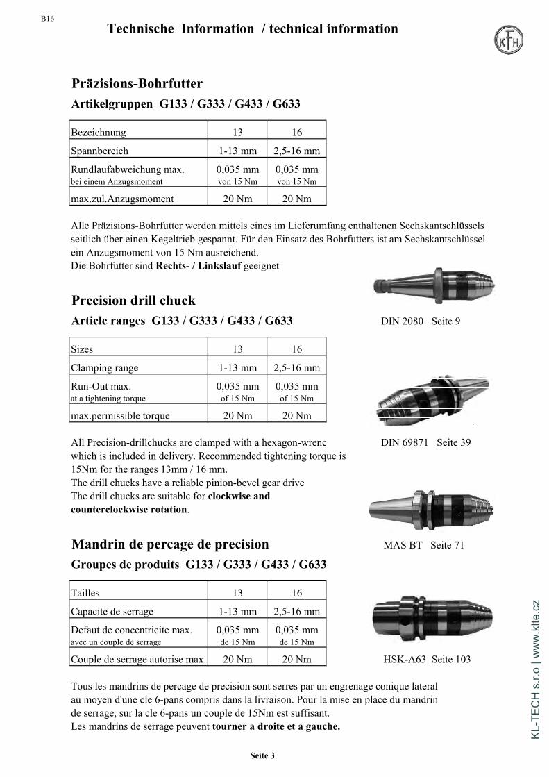
Präzisions-BohrfutterArtikelgruppen G133 / G333 / G433 / G633
Bezeichnung 13 16
Spannbereich 1-13 mm 2,5-16 mm
Rundlaufabweichung max. 0,035 mm 0,035 mmbei einem Anzugsmoment von 15 Nm von 15 Nm
max.zul.Anzugsmoment 20 Nm 20 Nm
Alle Präzisions-Bohrfutter werden mittels eines im Lieferumfang enthaltenen Sechskantschlüsselsseitlich über einen Kegeltrieb gespannt. Für den Einsatz des Bohrfutters ist am Sechskantschlüsselein Anzugsmoment von 15 Nm ausreichend.Die Bohrfutter sind Rechts- / Linkslauf geeignet
Precision drill chuckArticle ranges G133 / G333 / G433 / G633 DIN 2080 Seite 9
Sizes 13 16
Clamping range 1-13 mm 2,5-16 mm
Run-Out max. 0,035 mm 0,035 mmat a tightening torque of 15 Nm of 15 Nm
max.permissible torque 20 Nm 20 Nm
All Precision-drillchucks are clamped with a hexagon-wrenc DIN 69871 Seite 39which is included in delivery. Recommended tightening torque is15Nm for the ranges 13mm / 16 mm.The drill chucks have a reliable pinion-bevel gear driveThe drill chucks are suitable for clockwise andcounterclockwise rotation.
Mandrin de percage de precision MAS BT Seite 71
Groupes de produits G133 / G333 / G433 / G633
Tailles 13 16
Capacite de serrage 1-13 mm 2,5-16 mm
Defaut de concentricite max. 0,035 mm 0,035 mmavec un couple de serrage de 15 Nm de 15 Nm
Couple de serrage autorise max. 20 Nm 20 Nm HSK-A63 Seite 103
Tous les mandrins de percage de precision sont serres par un engrenage conique lateralau moyen d'une cle 6-pans compris dans la livraison. Pour la mise en place du mandrinde serrage, sur la cle 6-pans un couple de 15Nm est suffisant.Les mandrins de serrage peuvent tourner a droite et a gauche.
Seite 3
KL-T
ECH
s.r.
o | w
ww
.klte
.cz
B16Werkzeugaufnahmen / Toolholders DIN 2080
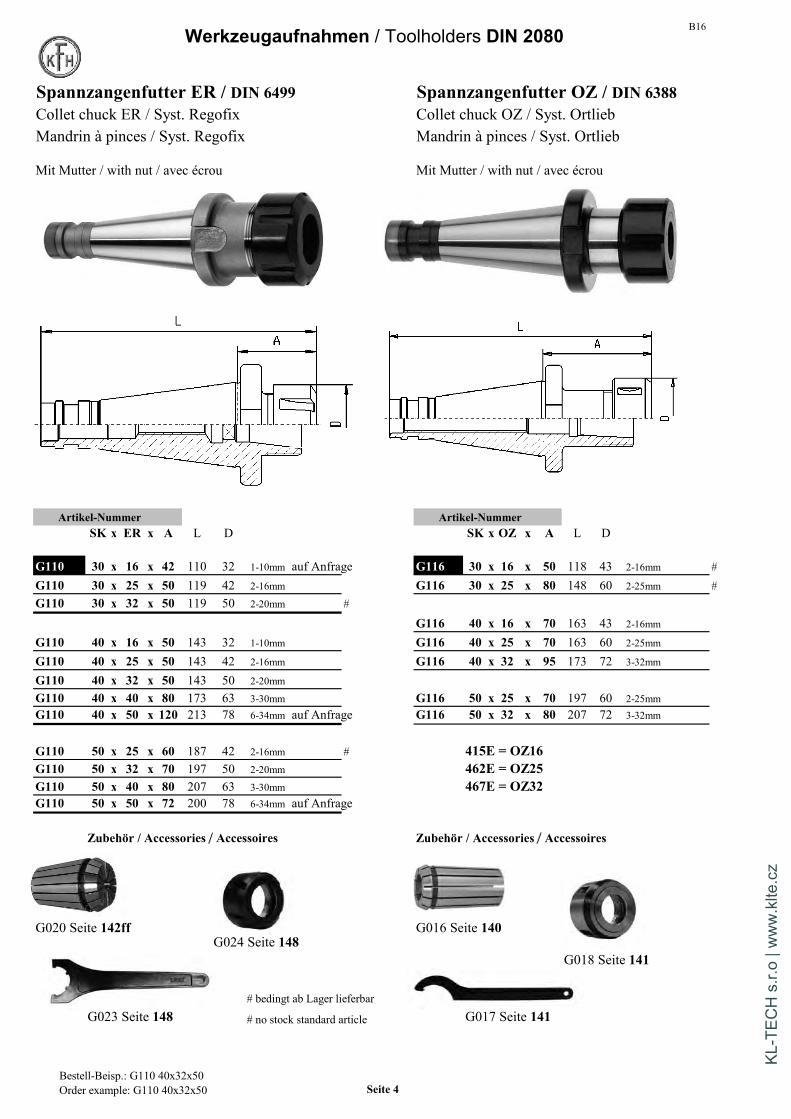
Spannzangenfutter ER / DIN 6499 Spannzangenfutter OZ / DIN 6388Collet chuck ER / Syst. Regofix Collet chuck OZ / Syst. OrtliebMandrin à pinces / Syst. Regofix Mandrin à pinces / Syst. Ortlieb
Mit Mutter / with nut / avec écrou Mit Mutter / with nut / avec écrou
Artikel-Nummer Artikel-NummerSK x ER x A L D SK x OZ x A L D
G110 30 x 16 x 42 110 32 1-10mm auf Anfrage G116 30 x 16 x 50 118 43 2-16mm #
G110 30 x 25 x 50 119 42 2-16mm G116 30 x 25 x 80 148 60 2-25mm #G110 30 x 32 x 50 119 50 2-20mm #
G116 40 x 16 x 70 163 43 2-16mm
G110 40 x 16 x 50 143 32 1-10mm G116 40 x 25 x 70 163 60 2-25mm
G110 40 x 25 x 50 143 42 2-16mm G116 40 x 32 x 95 173 72 3-32mm
G110 40 x 32 x 50 143 50 2-20mm
G110 40 x 40 x 80 173 63 3-30mm G116 50 x 25 x 70 197 60 2-25mmG110 40 x 50 x 120 213 78 6-34mm auf Anfrage G116 50 x 32 x 80 207 72 3-32mm
G110 50 x 25 x 60 187 42 2-16mm # 415E = OZ16G110 50 x 32 x 70 197 50 2-20mm 462E = OZ25G110 50 x 40 x 80 207 63 3-30mm 467E = OZ32G110 50 x 50 x 72 200 78 6-34mm auf Anfrage
Zubehör / Accessories / Accessoires Zubehör / Accessories / Accessoires
G020 Seite 142ff G016 Seite 140G024 Seite 148
G018 Seite 141
# bedingt ab Lager lieferbarG023 Seite 148 # no stock standard article G017 Seite 141
Bestell-Beisp.: G110 40x32x50Order example: G110 40x32x50 Seite 4
KL-T
ECH
s.r.
o | w
ww
.klte
.cz
B16 Werkzeugaufnahmen / Toolholders DIN 2080
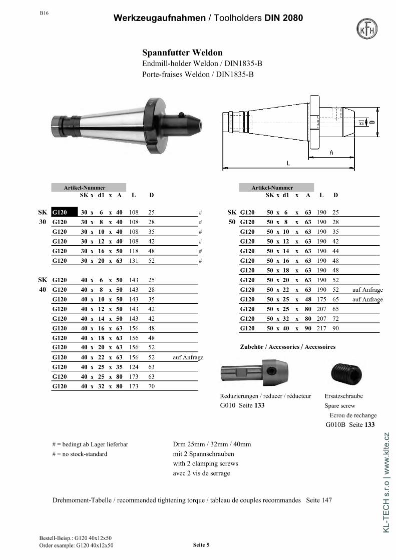
Spannfutter WeldonEndmill-holder Weldon / DIN1835-BPorte-fraises Weldon / DIN1835-B
Artikel-Nummer Artikel-NummerSK x d1 x A L D SK x d1 x A L D
SK G120 30 x 6 x 40 108 25 # SK G120 50 x 6 x 63 190 2530 G120 30 x 8 x 40 108 28 # 50 G120 50 x 8 x 63 190 28
G120 30 x 10 x 40 108 35 # G120 50 x 10 x 63 190 35G120 30 x 12 x 40 108 42 # G120 50 x 12 x 63 190 42G120 30 x 16 x 50 118 48 # G120 50 x 14 x 63 190 44G120 30 x 20 x 63 131 52 # G120 50 x 16 x 63 190 48
G120 50 x 18 x 63 190 48SK G120 40 x 6 x 50 143 25 G120 50 x 20 x 63 190 5240 G120 40 x 8 x 50 143 28 G120 50 x 22 x 63 190 52 auf Anfrage
G120 40 x 10 x 50 143 35 G120 50 x 25 x 48 175 65 auf AnfrageG120 40 x 12 x 50 143 42 G120 50 x 25 x 80 207 65G120 40 x 14 x 50 143 42 G120 50 x 32 x 80 207 72G120 40 x 16 x 63 156 48 G120 50 x 40 x 90 217 90G120 40 x 18 x 63 156 48G120 40 x 20 x 63 156 52 Zubehör / Accessories / Accessoires
G120 40 x 22 x 63 156 52 auf AnfrageG120 40 x 25 x 35 124 63G120 40 x 25 x 80 173 63G120 40 x 32 x 80 173 70
Reduzierungen / reducer / réducteur ErsatzschraubeG010 Seite 133 Spare screw
Ecrou de rechangeG010B Seite 133
# = bedingt ab Lager lieferbar Drm 25mm / 32mm / 40mm# = no stock-standard mit 2 Spannschrauben
with 2 clamping screwsavec 2 vis de serrage
Drehmoment-Tabelle / recommended tightening torque / tableau de couples recommandes Seite 147
Bestell-Beisp.: G120 40x12x50Order example: G120 40x12x50 Seite 5
KL-T
ECH
s.r.
o | w
ww
.klte
.cz

B16Werkzeugaufnahmen / Toolholders DIN 2080
Gewindeschneid-Schnellwechselfutter Spannfutter Whistle Notch DIN 1835-Emit Längenausgleich auf Druck und Zug
Quick change tapping chuck with compens. Endmill-holder Whistle Notch
Mandrin de taraudage à changement rapide Porte-fraises Whistle Notchavec compensation de longueur sur pression/traction.
Artikel-Nummer Artikel-Nummer
SK x Gr. A d D Gewinde SK x d1 x A L D
G117 30 x 1 51 19 38 M3-12 # SK G121 40 x 6 x 50 143 25 Anfrage #G117 30 x 2 86 31 55 M8-20 # 40 G121 40 x 8 x 50 143 28 Anfrage #
G121 40 x 10 x 50 143 35 Anfrage #G117 40 x 1 53 19 38 M3-12 G121 40 x 12 x 50 143 42 Anfrage #G117 40 x 2 77 31 55 M8-20 G121 40 x 14 x 50 143 42 Anfrage #G117 40 x 3 118 48 79 M14-33 G121 40 x 16 x 63 156 48 Anfrage #
G121 40 x 18 x 63 156 48 Anfrage #G117 50 x 1 57 19 38 M3-12 G121 40 x 20 x 63 156 52 Anfrage #G117 50 x 2 79 31 55 M8-20 G121 40 x 25 x 80 173 63 Anfrage #G117 50 x 3 125 48 79 M14-33 G121 40 x 32 x 80 173 70 Anfrage #G117 50 x 4 143 60 98 M22-48 auf Anfrage
SK G121 50 x 6 x 63 190 25 Anfrage #Zubehör / Accessories / Accessoires 50 G121 50 x 8 x 63 190 28 Anfrage #
mit Kupplung G121 50 x 10 x 63 190 35 Anfrage #with clutch / avec coupleur G121 50 x 12 x 63 190 42 Anfrage #G013 mit Seite 139 G121 50 x 14 x 63 190 44 Anfrage #
G121 50 x 16 x 63 190 48 Anfrage #G121 50 x 18 x 63 190 48 Anfrage #
ohne Kupplung G121 50 x 20 x 63 190 52 Anfrage #without clutch / sans coupleur G121 50 x 25 x 80 207 65 Anfrage #G013 ohne Seite 139 G121 50 x 32 x 80 207 72 Anfrage #
G121 50 x 40 x 90 217 90 Anfrage ## = bedingt ab Lager lieferbar# = no stock-standard # Lagerabverkauf - keine Neuauflage mehr
obsolete article with rest stock levelsTabelle mit Gewindebohrer-Schaftmaßensiehe Seite 138
Bestell-Beisp.: G117 40x1Order example: G117 40x1 Seite 6
KL-T
ECH
s.r.
o | w
ww
.klte
.cz

B16 Gewindebohrer-SchaftmaßeDimensions des queues de tarauds
Hand- Feingewinde Feingewinde Regelgewinde Regel- ZollGewinde-Bohrer Zoll verstärkter Überlauf Überlauf Gewinde Überlauf
Kurze Bauart Schaft Schaft Schaft Zoll Schaft
Tarauds à mainversion courte en pouces
Filetage fin,queue
renforcéeFiletage finqueue
Filetagestandard queue
Filetagestandard enpouces
En poucesqueue
SchaftmaßDurchm x DIN 352 DIN 353 DIN 371 DIN 374 DIN 376 DIN 2182 DIN 2183Vierkant
Dimen. queue M 1 M 1 M 3,5 1/16"Diam. x carré M 1,1 M 1,1 M 3,5
M 1,2 M 1,22,5 x 2,1 M 1,4 M 1,4
M 1,6 M 1,6M 1,8 M 1,8M 2 M 2 M 4 M 4 3/32" 5/32"
2,8 x 2,1 M 2,2 M 2,2M 2,5 M 2,5
3,5 x 2,7 M 3 M 3 M 5 M 5 1/8"4 x 3 M 3,5 M 3,5 7/32"
4,5 x 3,4 M 4 M 4 M 6 M 6 5/32" 1/4"M 5 M 5
6 x 4,9 M 6 M 6M 8 M 8 M 8
7 x 5,5 M 10 G 1/8" M 10 M 10 1/4" 3/8"8 x 6,2 M 8 5/16" 7/16"9 x 7 M 12 M 12 M 12 3/8" 1/2"10 x 8 M 1011 x 9 M 14 G 1/4" M 14 M 14 9/16"12 x 9 M 16 G 3/8" M 16 M 16 5/8"14 x 11 M 18 M 18 M 18 11/16"16 x 12 M 20 G 1/2" M 20 M 20 13/16"18 x 14,5 M 22 G 5/8" M 22 M 22 7/8"
M 24 M 24 M 24 15/16"20 x 16 M 27 G 3/4" M 27 M 27 1"22 x 18 M 30 G 7/8" M 30 M 30 1.1/8"25 x 20 M 33 G 1" M 33 M 33 1.1/4"28 x 22 M 36 G 1.1/8" M 36 M 36 1.3/8"32 x 24 M 39 G 1.1/4" M 39 M 39 1.1/2"
M 42 M 42 M 42 1.5/8"M 45 G 1.3/8" M 45 M 45 1.3/4"
36 x 29 M 48 G 1.1/2" M 48 M 48 1.7/8"G 1.3/4"G 2"
40 x 32 M 52 G 2.1/4" M 52 M 52 2"45 x 35 M 56 G 2.1/2" M 56 2.1/4"
M 60 M 60 2.1/2"50 x 39 M 64 G 2.3/4" M 64 2.1/2"
G 3"56 x 44 M 68 G 3.1/4" M 68 2.3/4"
Seite 7
KL-T
ECH
s.r.
o | w
ww
.klte
.cz
B16Werkzeugaufnahmen / Toolholders DIN 2080
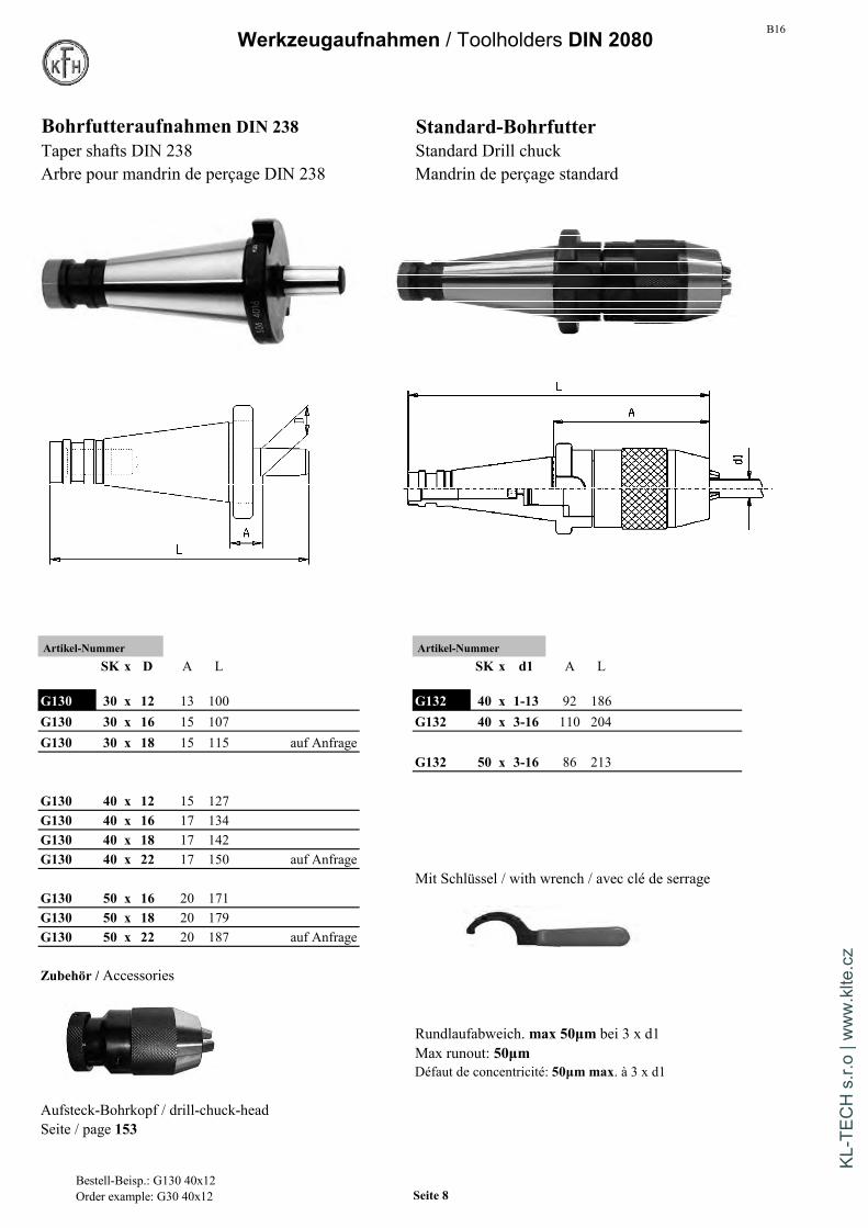
Bohrfutteraufnahmen DIN 238 Standard-BohrfutterTaper shafts DIN 238 Standard Drill chuckArbre pour mandrin de perçage DIN 238 Mandrin de perçage standard
Artikel-Nummer Artikel-NummerSK x D A L SK x d1 A L
G130 30 x 12 13 100 G132 40 x 1-13 92 186G130 30 x 16 15 107 G132 40 x 3-16 110 204G130 30 x 18 15 115 auf Anfrage
G132 50 x 3-16 86 213
G130 40 x 12 15 127G130 40 x 16 17 134G130 40 x 18 17 142G130 40 x 22 17 150 auf Anfrage
Mit Schlüssel / with wrench / avec clé de serrageG130 50 x 16 20 171G130 50 x 18 20 179G130 50 x 22 20 187 auf Anfrage
Zubehör / Accessories
Rundlaufabweich. max 50µm bei 3 x d1Max runout: 50µmDéfaut de concentricité: 50µm max. à 3 x d1
Aufsteck-Bohrkopf / drill-chuck-headSeite / page 153
Bestell-Beisp.: G130 40x12Order example: G30 40x12 Seite 8
KL-T
ECH
s.r.
o | w
ww
.klte
.cz

B16 Werkzeugaufnahmen / Toolholders DIN 2080
Präzisions-Bohrfutter Hoch-Präzisions-BohrfutterRechts-/ Linkslauf geeignet Rechts-/ Linkslauf geeignet
Precision drill chuck High precision drill chuckfor left- and right-hand rotation for left- and right-hand rotationMandrin de percage CNC Mandrin de percage haute precisionpour rotation gauche-droite pour rotation gauche-droite
Artikel-Nummer Form A Artikel-NummerSK x d1 A D Bereich SK x d1 A D Bereich
G133 40 x 13 83 50 1-13 G134 30 x 08 60 36 0,5-8G133 40 x 16 88 50 2,5-16 G134 30 x 13 98 50 1-13
G133 50 x 13 110 50 1-13 G134 40 x 08 62 36 0,5-8G133 50 x 16 115 50 2,5-16 G134 40 x 13 83 50 1-13
G134 40 x 16 88 57 2,5-16
G134 50 x 13 110 50 1-13Mit Schlüssel / with wrench / avec clé de serrage G134 50 x 16 115 57 2,5-16
Mit Schlüssel / with wrench / avec clé de serrage
Rundlaufabweich. max 35µm bei 3 x d1 Rundlaufabweich. max 20µm bei 3 x d1Max runout: 35µm Max runout: 20µmDéfaut de concentricité: 35µm max. à 3 x d1 Défaut de concentricité: 20µm max. à 3 x d1
Weitere techn. Informationen / Anzugsmomente S. 75 Weitere techn. Info. / Anzugsmomente S. 137Further technical information / tightening torque page 75 Further technical info. / tightening torque page 137
Bestell-Beisp.: G133 40x13Order example: G133 40x13 Seite 9
KL-T
ECH
s.r.
o | w
ww
.klte
.cz

B16Werkzeugaufnahmen / Toolholders DIN 2080
Kombi-Aufsteckfräserdorn DIN 6358Combi shell mill holderPorte-fraise à double usage
Artikel-Nummer Zubehör / AccessoriesSK x d1 x A L l1 l5 l6 d2
SK G140 30 x 16 x 35 120 27 17 25 32 auf Anfrage30 G140 30 x 22 x 35 122 31 19 25 40
G140 30 x 27 x 35 124 33 21 25 48 G040 Seite 154G140 30 x 32 x 50 142 38 24 40 58
SK G140 40 x 16 x 52 162 27 17 40 3240 G140 40 x 22 x 52 164 31 19 40 40
G140 40 x 27 x 52 166 33 21 40 48G140 40 x 32 x 52 169 38 24 40 58G140 40 x 32 x 75 192 38 24 63 58 auf AnfrageG140 40 x 40 x 52 172 41 27 40 70 G041 Seite 154G140 40 x 40 x 75 195 41 27 63 70 auf AnfrageG140 40 x 50 x 52 177 46 30 40 90 auf Anfrage
SK G140 50 x 16 x 55 199 27 17 40 3250 G140 50 x 22 x 55 201 31 19 40 40
G140 50 x 27 x 55 203 33 21 40 48 G042 Schlüssel DIN 6368 fürG140 50 x 32 x 55 206 38 24 40 58 Aufsteckfräserdorn s.S. 154G140 50 x 40 x 55 209 41 27 40 70 Wrenches DIN 6368 see page 154G140 50 x 50 x 55 212 46 30 40 90 G042 clé DIN 6368 pour
porte-fraise voir page 154
Mit Fräseranzugsschraube, Paßfeder und MitnehmerringWith screw, key and drive-ringAvec vis de serrage, clavette et bague d'entraînement
Bestell-Beisp.: G140 40x16x 52Order example: G140 40x16x 52 Seite 10
KL-T
ECH
s.r.
o | w
ww
.klte
.cz
B16 Werkzeugaufnahmen / Toolholders DIN 2080
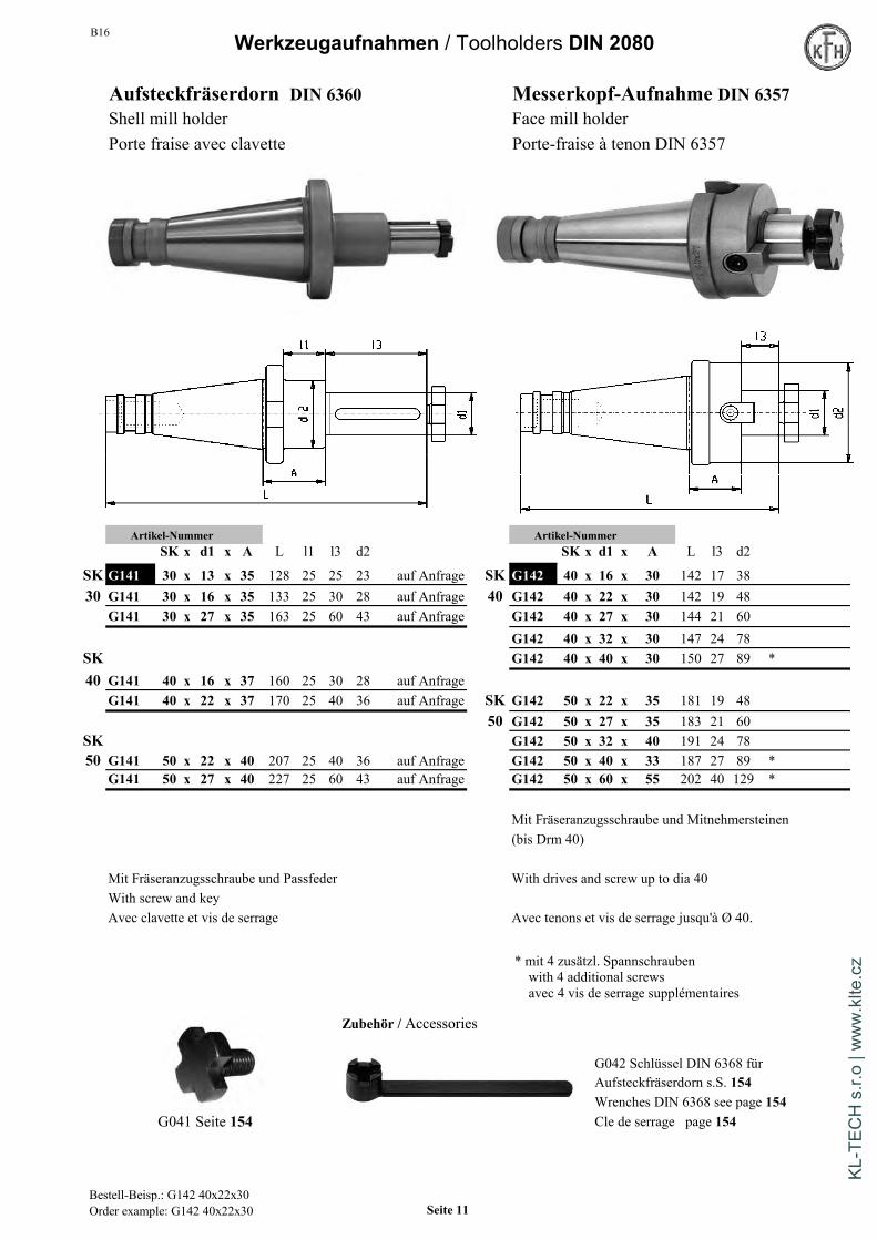
Aufsteckfräserdorn DIN 6360 Messerkopf-Aufnahme DIN 6357Shell mill holder Face mill holderPorte fraise avec clavette Porte-fraise à tenon DIN 6357
Artikel-Nummer Artikel-NummerSK x d1 x A L l1 l3 d2 SK x d1 x A L l3 d2
SK G141 30 x 13 x 35 128 25 25 23 auf Anfrage SK G142 40 x 16 x 30 142 17 3830 G141 30 x 16 x 35 133 25 30 28 auf Anfrage 40 G142 40 x 22 x 30 142 19 48
G141 30 x 27 x 35 163 25 60 43 auf Anfrage G142 40 x 27 x 30 144 21 60G142 40 x 32 x 30 147 24 78
SK G142 40 x 40 x 30 150 27 89 *40 G141 40 x 16 x 37 160 25 30 28 auf Anfrage
G141 40 x 22 x 37 170 25 40 36 auf Anfrage SK G142 50 x 22 x 35 181 19 4850 G142 50 x 27 x 35 183 21 60
SK G142 50 x 32 x 40 191 24 7850 G141 50 x 22 x 40 207 25 40 36 auf Anfrage G142 50 x 40 x 33 187 27 89 *
G141 50 x 27 x 40 227 25 60 43 auf Anfrage G142 50 x 60 x 55 202 40 129 *
Mit Fräseranzugsschraube und Mitnehmersteinen(bis Drm 40)
Mit Fräseranzugsschraube und Passfeder With drives and screw up to dia 40With screw and keyAvec clavette et vis de serrage Avec tenons et vis de serrage jusqu'à Ø 40.
Zubehör / Accessories
G042 Schlüssel DIN 6368 fürAufsteckfräserdorn s.S. 154Wrenches DIN 6368 see page 154
G041 Seite 154 Cle de serrage page 154
* mit 4 zusätzl. Spannschraubenwith 4 additional screwsavec 4 vis de serrage supplémentaires
Bestell-Beisp.: G142 40x22x30Order example: G142 40x22x30 Seite 11
KL-T
ECH
s.r.
o | w
ww
.klte
.cz
B16Werkzeugaufnahmen / Toolholders DIN 2080
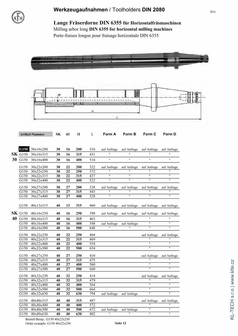
Lange Fräserdorne DIN 6355 für HorizontalfräsmaschinenMilling arbor long DIN 6355 for horizontal milling machinesPorte-fraises longue pour fraisage horizontale DIN 6355
Artikel-Nummer SK d1 l1 L Form A Form B Form C Form D
€ / St. € / St.
G150 30x16x200 30 16 200 316 auf Anfrage auf Anfrage auf Anfrage auf AnfrageSK G150 30x16x315 30 16 315 431 " " " "30 G150 30x16x400 30 16 400 516 " " " "
G150 30x22x200 30 22 200 322 auf Anfrage auf Anfrage auf Anfrage auf AnfrageG150 30x22x250 30 22 250 372 " " " "G150 30x22x315 30 22 315 437 " " " "G150 30x22x400 30 22 400 522 " " " "
G150 30x27x200 30 27 200 328 auf Anfrage auf Anfrage auf Anfrage auf AnfrageG150 30x27x315 30 27 315 443 " " " "G150 30x27x400 30 27 400 528 " " " "
G150 40x13x315 40 13 315 460 auf Anfrage auf Anfrage auf Anfrage auf Anfrage
SK G150 40x16x250 40 16 250 398 auf Anfrage auf Anfrage auf Anfrage auf Anfrage40 G150 40x16x315 40 16 315 463 " "
G150 40x16x400 40 16 400 548 auf Anfrage auf Anfrage " "G150 40x16x500 40 16 500 648 " " " "
G150 40x22x250 40 22 250 404 auf Anfrage auf AnfrageG150 40x22x315 40 22 315 469 " "G150 40x22x400 40 22 400 554 " "G150 40x22x500 40 22 500 654 " "
G150 40x27x250 40 27 250 410 auf Anfrage auf AnfrageG150 40x27x315 40 27 315 475 " "G150 40x27x400 40 27 400 560 " "G150 40x27x500 40 27 500 660 " "
G150 40x32x250 40 32 250 414 auf Anfrage auf AnfrageG150 40x32x315 40 32 315 479 " "G150 40x32x400 40 32 400 564 " "G150 40x32x500 40 32 500 664 " "G150 40x32x630 40 32 630 794 auf Anfrage auf Anfrage " "
G150 40x40x315 40 40 315 487 auf Anfrage auf AnfrageG150 40x40x400 40 40 400 572 " "G150 40x40x500 40 40 500 672 auf Anfrage auf Anfrage " "G150 40x40x630 40 40 630 802 " " " "
Bestell-Beisp.: G150 40x22x250Order example: G150 40x22x250 Seite 12
KL-T
ECH
s.r.
o | w
ww
.klte
.cz

B16 Werkzeugaufnahmen / Toolholders DIN 2080Lange Fräserdorne / Milling arbor long DIN 6355
Artikel-Nummer SK d1 l1 L Form A Form B Form C Form D€ / St. € / St.
SK G150 50x16x315 50 16 315 505 auf Anfrage auf Anfrage auf Anfrage auf Anfrage50 G150 50x16x400 50 16 400 590 " " " "
G150 50x22x400 50 22 400 596 auf Anfrage auf AnfrageG150 50x22x500 50 22 500 696 " "
G150 50x27x315 50 27 315 517 auf Anfrage auf Anfrage auf Anfrage auf AnfrageG150 50x27x400 50 27 400 602 auf Anfrage auf Anfrage " "G150 50x27x500 50 27 500 702 " "G150 50x27x630 50 27 630 832 " "G150 50x27x800 50 27 800 1002 auf Anfrage auf Anfrage " "
G150 50x32x400 50 32 400 606 auf Anfrage auf AnfrageG150 50x32x500 50 32 500 706 " "G150 50x32x630 50 32 630 836 " "
G150 50x40x400 50 40 400 614 auf Anfrage auf AnfrageG150 50x40x500 50 40 500 714 " "G150 50x40x630 50 40 630 844 " "G150 50x40x800 50 40 800 1014 " "
G150 50x50x500 50 50 500 720 auf Anfrage auf AnfrageG150 50x50x630 50 50 630 850 " "G150 50x50x800 50 50 800 1020 " "
G150 50x60x500 50 60 500 730 auf Anfrage auf Anfrage auf Anfrage auf AnfrageG150 50x60x630 50 60 630 860 auf Anfrage auf Anfrage " "
Form A: Fräserdorn mit Mutter und Passfeder Angaben zur Rundlaufabweich.Form B: Fräserdorn mit Mutter, Ringsatz und Passfeder auf Seite 50Form C: Fräserdorn mit Mutter, 1 Laufbuchse Ringsatz und PassfederForm D: Fräserdorn mit Mutter, 2 Laufbuchsen Ringsatz und Passfeder
Bei Form C und D geben Sie bitte die gewünschten Laufbuchsenmaße an.
Form A:Milling arbor with nut and feather key Information accordingForm B: Milling arbor with nut, feather key and set of spacing collars runout-accuracy see page 50Form C: Milling arbor with nut, feather key, set of spacing collars and 1 bearing collarForm D: Milling arbor with nut, feather key, set of spacing collars and 2 bearing collars
At Form C and D please mention the needed dimensions of the bearing collars
Form A:Mandrin avec écrou et clavette Informations pourForm B: Mandrin avec écrou, clavette et set bague d'extremité défaut de concentricité page 50Form C: Mandrin avec écrou, clavette, set bague d'extremité et 1 douille de glissementForm D: Mandrin avec écrou, clavette, set bague d'extremité et 2 douilles de glissement
Pour Form C et D, veuillez indiquer les dimension des douilles de glissement
Zubehör / Accessories
Seite / page 152 Seite / page 152 Seite / page 150 Seite / page 151
Bestell-Beisp.: G150 50x32x500Order example: G150 50x32x500 Seite 13
KL-T
ECH
s.r.
o | w
ww
.klte
.cz

B16
Werkzeugaufnahmen / Toolholders DIN 2080
Kurze Einsatzhülsen f. MK m. LappenDIN 6383 Kurze Fräserhülsen f. MK m. GewindeDIN 6364Morse taper adaptor for flat tang Morse taper adaptor with draw thread
Douilles intermédiares à cône morse Douilles intermédiares à cône morse à trou fileté
Artikel-Nummer Artikel-NummerSK x MK x A L D SK xMK x A L D
G160 30 x 1 x 50 118 25 G161 30 x 1 x 50 118 25 auf AnfrageG160 30 x 2 x 50 118 32 G161 30 x 2 x 50 118 32 auf AnfrageG160 30 x 3 x 75 143 40 G161 30 x 3 x 77 145 40 auf Anfrage
G160 40 x 1 x 50 143 25 G161 40 x 1 x 50 143 25G160 40 x 2 x 50 143 32 G161 40 x 2 x 50 143 32G160 40 x 3 x 65 158 40 G161 40 x 3 x 65 158 40G160 40 x 4 x 95 188 48 G161 40 x 4 x 95 188 48
G160 50 x 1 x 45 172 25 G161 50 x 1 x 60 187 25G160 50 x 2 x 50 177 32 G161 50 x 2 x 60 187 32G160 50 x 3 x 65 192 40 G161 50 x 3 x 65 192 40G160 50 x 4 x 70 197 48 G161 50 x 4 x 65 192 48G160 50 x 5 x 105 232 63 G161 50 x 5 x 120 247 63
In SK40 und SK50 noch größere Restposten in langer Ausführung A=Maß 100,150 und 200 auf Anfrage
Bestell-Beisp.: G160 40x1x50Order example: G160 40x1x50 Seite 14
KL-T
ECH
s.r.
o | w
ww
.klte
.cz
B16
Werkzeugaufnahmen / Toolholders DIN 2080
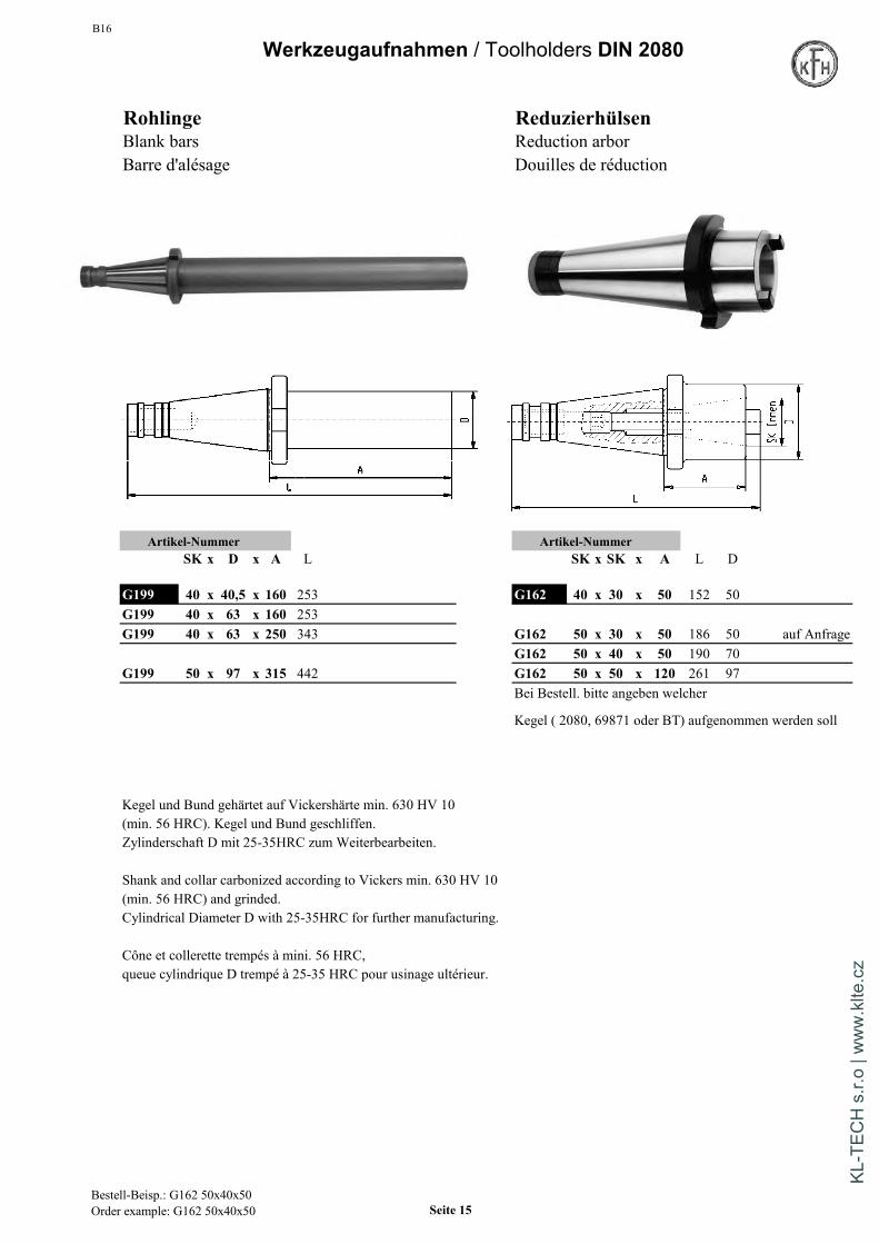
Rohlinge ReduzierhülsenBlank bars Reduction arborBarre d'alésage Douilles de réduction
Artikel-Nummer Artikel-NummerSK x D x A L SK x SK x A L D
G199 40 x 40,5 x 160 253 G162 40 x 30 x 50 152 50G199 40 x 63 x 160 253G199 40 x 63 x 250 343 G162 50 x 30 x 50 186 50 auf Anfrage
G162 50 x 40 x 50 190 70G199 50 x 97 x 315 442 G162 50 x 50 x 120 261 97
Bei Bestell. bitte angeben welcher
Kegel ( 2080, 69871 oder BT) aufgenommen werden soll
Kegel und Bund gehärtet auf Vickershärte min. 630 HV 10(min. 56 HRC). Kegel und Bund geschliffen.Zylinderschaft D mit 25-35HRC zum Weiterbearbeiten.
Shank and collar carbonized according to Vickers min. 630 HV 10(min. 56 HRC) and grinded.Cylindrical Diameter D with 25-35HRC for further manufacturing.
Cône et collerette trempés à mini. 56 HRC,queue cylindrique D trempé à 25-35 HRC pour usinage ultérieur.
Bestell-Beisp.: G162 50x40x50Order example: G162 50x40x50 Seite 15
KL-T
ECH
s.r.
o | w
ww
.klte
.cz
B16
Werkzeugaufnahmen Deckel S20 x 2
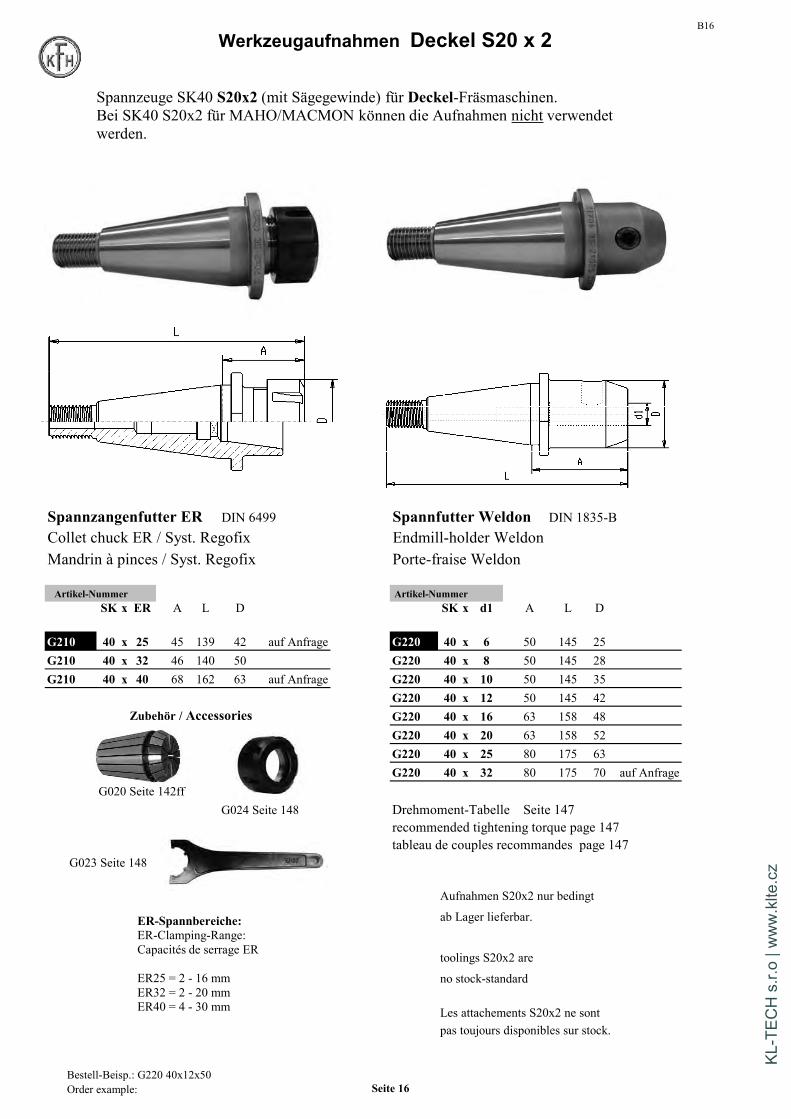
Spannzangenfutter ER DIN 6499 Spannfutter Weldon DIN 1835-BCollet chuck ER / Syst. Regofix Endmill-holder WeldonMandrin à pinces / Syst. Regofix Porte-fraise Weldon
Artikel-Nummer Artikel-NummerSK x ER A L D SK x d1 A L D
G210 40 x 25 45 139 42 auf Anfrage G220 40 x 6 50 145 25G210 40 x 32 46 140 50 G220 40 x 8 50 145 28G210 40 x 40 68 162 63 auf Anfrage G220 40 x 10 50 145 35
G220 40 x 12 50 145 42Zubehör / Accessories G220 40 x 16 63 158 48
G220 40 x 20 63 158 52G220 40 x 25 80 175 63G220 40 x 32 80 175 70 auf Anfrage
G020 Seite 142ffG024 Seite 148 Drehmoment-Tabelle Seite 147
recommended tightening torque page 147tableau de couples recommandes page 147
G023 Seite 148
Aufnahmen S20x2 nur bedingt
ab Lager lieferbar.
toolings S20x2 are
no stock-standard
Les attachements S20x2 ne sontpas toujours disponibles sur stock.
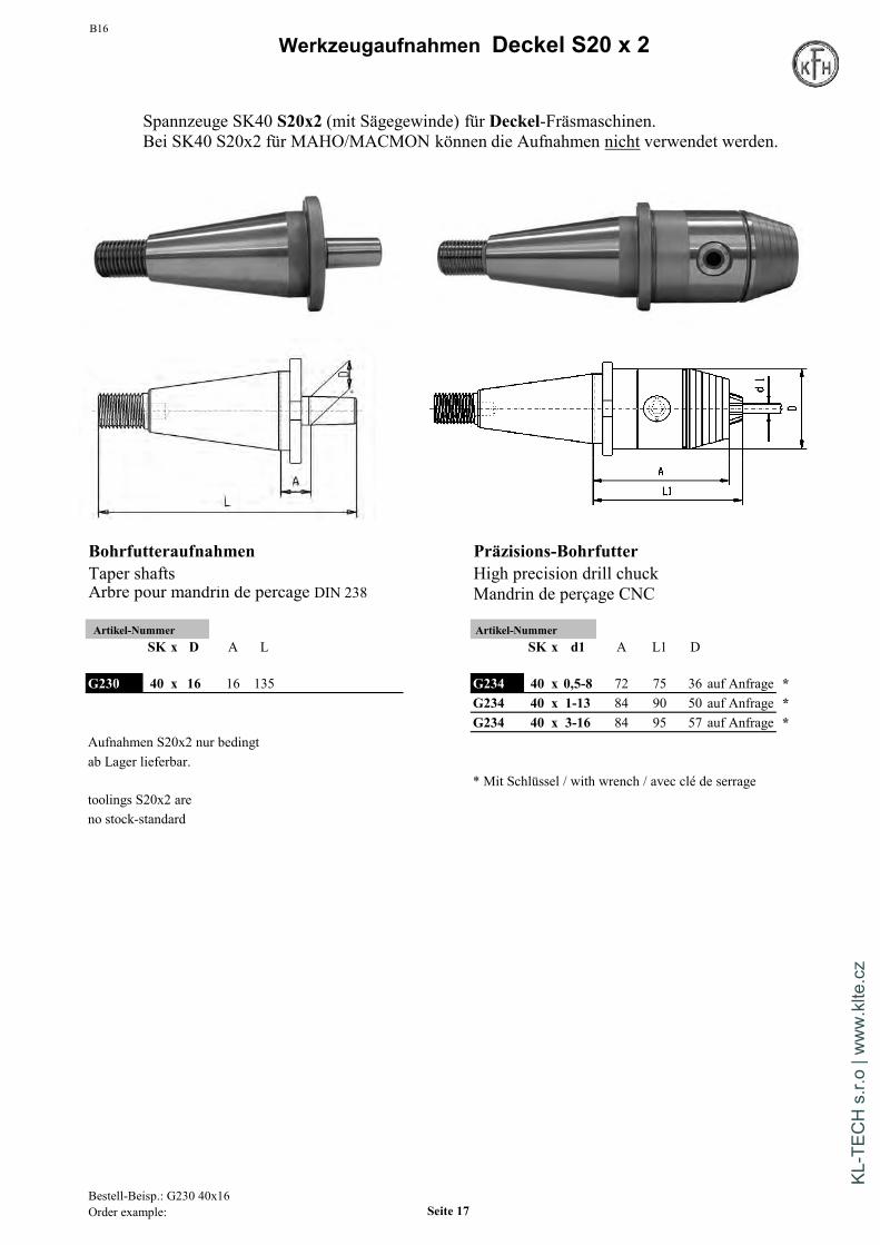
Spannzeuge SK40 S20x2 (mit Sägegewinde) für Deckel-Fräsmaschinen.Bei SK40 S20x2 für MAHO/MACMON können die Aufnahmen nicht verwendetwerden.
ER-Spannbereiche:ER-Clamping-Range:Capacités de serrage ER
ER25 = 2 - 16 mmER32 = 2 - 20 mmER40 = 4 - 30 mm
Bestell-Beisp.: G220 40x12x50Order example: Seite 16
KL-T
ECH
s.r.
o | w
ww
.klte
.cz
B16
Werkzeugaufnahmen Deckel S20 x 2
Bohrfutteraufnahmen Präzisions-BohrfutterTaper shafts High precision drill chuckArbre pour mandrin de percage DIN 238 Mandrin de perçage CNC
Artikel-Nummer Artikel-NummerSK x D A L SK x d1 A L1 D
G230 40 x 16 16 135 G234 40 x 0,5-8 72 75 36 auf Anfrage *G234 40 x 1-13 84 90 50 auf Anfrage *G234 40 x 3-16 84 95 57 auf Anfrage *
Aufnahmen S20x2 nur bedingtab Lager lieferbar.
* Mit Schlüssel / with wrench / avec clé de serragetoolings S20x2 areno stock-standard
Spannzeuge SK40 S20x2 (mit Sägegewinde) für Deckel-Fräsmaschinen.Bei SK40 S20x2 für MAHO/MACMON können die Aufnahmen nicht verwendet werden.
Bestell-Beisp.: G230 40x16Order example: Seite 17
KL-T
ECH
s.r.
o | w
ww
.klte
.cz
B16Werkzeugaufnahmen Deckel S20 x 2
Zubehör / Accessories
G040 Seite / Page 154
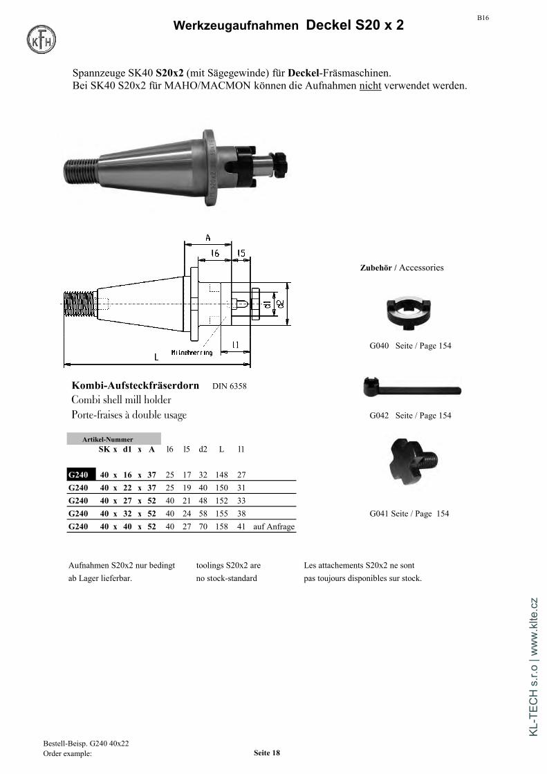
Kombi-Aufsteckfräserdorn DIN 6358
Combi shell mill holderPorte-fraises à double usage G042 Seite / Page 154
Artikel-NummerSK x d1 x A l6 l5 d2 L l1
G240 40 x 16 x 37 25 17 32 148 27G240 40 x 22 x 37 25 19 40 150 31G240 40 x 27 x 52 40 21 48 152 33G240 40 x 32 x 52 40 24 58 155 38 G041 Seite / Page 154G240 40 x 40 x 52 40 27 70 158 41 auf Anfrage
Aufnahmen S20x2 nur bedingt toolings S20x2 are Les attachements S20x2 ne sontab Lager lieferbar. no stock-standard pas toujours disponibles sur stock.
Spannzeuge SK40 S20x2 (mit Sägegewinde) für Deckel-Fräsmaschinen.Bei SK40 S20x2 für MAHO/MACMON können die Aufnahmen nicht verwendet werden.
Bestell-Beisp. G240 40x22Order example: Seite 18
KL-T
ECH
s.r.
o | w
ww
.klte
.cz

B16Werkzeugaufnahmen Deckel S20 x 2
Kurze Kombihülsen f. MK m. Gewinde
Morse taper adaptor with draw thread
Douilles intermédiares à cône morse à trou fileté
Artikel-NummerSK x MK x A L D
G263 40 x 1 x 50 144 25 auf AnfrageG263 40 x 2 x 50 144 32 auf AnfrageG263 40 x 3 x 65 160 40 auf AnfrageG263 40 x 4 x 95 189 48 auf Anfrage
Aufnahmen S20x2 nur bedingt toolings S20x2 are Les attachements S20x2 ne sontab Lager lieferbar. no stock-standard pas toujours disponibles sur stock.
Spannzeuge SK40 S20x2 (mit Sägegewinde) für Deckel-Fräsmaschinen.Bei SK40 S20x2 für MAHO/MACMON können die Aufnahmen nicht verwendet werden.
Bestell-Beisp. G260 40x2x50Order example: Seite 19
KL-T
ECH
s.r.
o | w
ww
.klte
.cz
B16Werkzeugaufnahmen / Toolholders DIN 69871
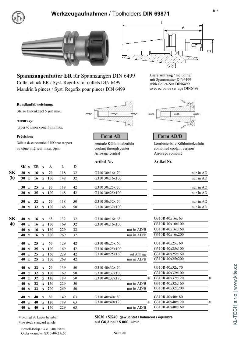
Spannzangenfutter ER für Spannzangen DIN 6499Collet chuck ER / Syst. Regofix for collets DIN 6499Mandrin à pinces / Syst. Regofix pour pinces DIN 6499
Rundlaufabweichung:
SK zu Innenkegel 5 µm max.
Accuracy:
taper to inner cone 5µm max.
Précision: Form AD Form AD/BDéfaut de concentricité ISO par rapport zentrale Kühlmittelzufuhr kombinierbare Kühlmittelzufuhrau cône intérieur maxi. 5µm coolant through center combined coolant version
Arrosage central Arrosage combiné
Artikel-Nr. Artikel-Nr.SK x ER x A L D
SK 30 x 16 x 70 118 32 G310 30x16x 70 nur in AD30 30 x 16 x 100 148 32 G310 30x16x100 nur in AD
30 x 25 x 70 118 42 G310 30x25x 70 nur in AD30 x 25 x 100 148 42 G310 30x25x100 nur in AD
30 x 32 x 70 118 50 G310 30x32x 70 nur in AD30 x 32 x 100 148 50 G310 30x32x100 nur in AD
SK 40 x 16 x 63 132 32 G310 40x16x 63 G310D 40x16x 6340 40 x 16 x 100 169 32 G310 40x16x100 G310D 40x16x100
40 x 16 x 160 229 32 nur in AD/B G310D 40x16x16040 x 16 x 200 269 32 nur in AD/B G310D 40x16x200
40 x 25 x 60 129 42 G310 40x25x 60 G310D 40x25x 6040 x 25 x 100 169 42 G310 40x25x100 G310D 40x25x10040 x 25 x 160 229 42 G310 40x25x160 auf Anfrage G310D 40x25x16040 x 25 x 200 269 42 nur in AD/B G310D 40x25x200
40 x 32 x 70 139 50 G310 40x32x 70 G310D 40x32x 7040 x 32 x 100 169 50 G310 40x32x100 G310D 40x32x10040 x 32 x 120 189 50 G310 40x32x120 # G310D 40x32x120 #40 x 32 x 160 229 50 nur in AD/B G310D 40x32x16040 x 32 x 200 269 50 nur in AD/B G310D 40x32x200
40 x 40 x 80 149 63 G310 40x40x 80 G310D 40x40x 8040 x 40 x 120 189 63 G310 40x40x120 # G310D 40x40x120 #40 x 40 x 160 229 63 nur in AD/B G310D 40x40x160
# bedingt ab Lager lieferbar SK30 +SK40 gewuchtet / balanced / equilibré# no stock standard article auf G6,3 bei 15.000 U/min
Lieferumfang / Including:mit Spannmutter DIN6499with Collet-Nut DIN6499avec ecrou de serrage DIN6499
Bestell-Beisp.: G310 40x25x60Order example: G310 40x25x60 Seite 20
KL-T
ECH
s.r.
o | w
ww
.klte
.cz
B16 Werkzeugaufnahmen / Toolholders DIN 69871
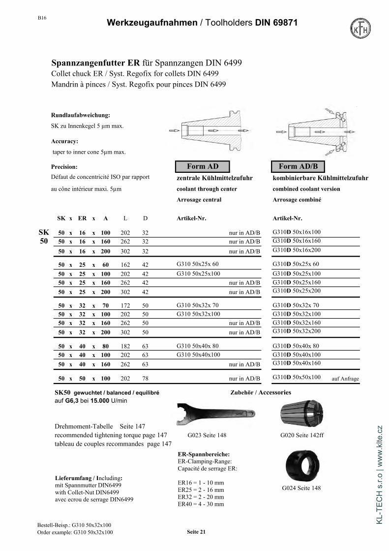
Spannzangenfutter ER für Spannzangen DIN 6499Collet chuck ER / Syst. Regofix for collets DIN 6499Mandrin à pinces / Syst. Regofix pour pinces DIN 6499
Rundlaufabweichung:
SK zu Innenkegel 5 µm max.
Accuracy:
taper to inner cone 5µm max.
Precision: Form AD Form AD/BDéfaut de concentricité ISO par rapport zentrale Kühlmittelzufuhr kombinierbare Kühlmittelzufuhrau cône intérieur maxi. 5µm coolant through center combined coolant version
Arrosage central Arrosage combiné
SK x ER x A L D Artikel-Nr. Artikel-Nr.
SK 50 x 16 x 100 202 32 nur in AD/B G310D 50x16x10050 50 x 16 x 160 262 32 nur in AD/B G310D 50x16x160
50 x 16 x 200 302 32 nur in AD/B G310D 50x16x200
50 x 25 x 60 162 42 G310 50x25x 60 G310D 50x25x 6050 x 25 x 100 202 42 G310 50x25x100 G310D 50x25x10050 x 25 x 160 262 42 nur in AD/B G310D 50x25x16050 x 25 x 200 302 42 nur in AD/B G310D 50x25x200
50 x 32 x 70 172 50 G310 50x32x 70 G310D 50x32x 7050 x 32 x 100 202 50 G310 50x32x100 G310D 50x32x10050 x 32 x 160 262 50 nur in AD/B G310D 50x32x16050 x 32 x 200 302 50 nur in AD/B G310D 50x32x200
50 x 40 x 80 182 63 G310 50x40x 80 G310D 50x40x 8050 x 40 x 100 202 63 G310 50x40x100 G310D 50x40x10050 x 40 x 160 262 63 nur in AD/B G310D 50x40x160
50 x 50 x 100 202 78 nur in AD/B G310D 50x50x100 auf Anfrage
SK50 gewuchtet / balanced / equilibré Zubehör / Accessoriesauf G6,3 bei 15.000 U/min
Drehmoment-Tabelle Seite 147recommended tightening torque page 147 G023 Seite 148 G020 Seite 142fftableau de couples recommandes page 147
G024 Seite 148Lieferumfang / Including:mit Spannmutter DIN6499with Collet-Nut DIN6499avec ecrou de serrage DIN6499
ER-Spannbereiche:ER-Clamping-Range:Capacité de serrage ER:
ER16 = 1 - 10 mmER25 = 2 - 16 mmER32 = 2 - 20 mmER40 = 4 - 30 mm
Bestell-Beisp.: G310 50x32x100Order example: G310 50x32x100 Seite 21
KL-T
ECH
s.r.
o | w
ww
.klte
.cz

Werkzeugaufnahmen / Toolholders DIN 69871
Hydro-DehnspannfutterHydraulic chuckMandrins hydrauliques Rundlaufabweichung:
SK zu Innenbohrung 3 µm max.
Form AD / BAccuracy:
kombinierbare Kühlmittelzufuhr taper to inner-bore 3µm max.combined coolant version
eau de refroidissement combiné Précision:Défaut de concentricité 3µm
Artikel-NummerSK x d1 A l2 D D1
G314D 40 x 6 x 80 40 49,5 26 auf Anfrage Zubehör / AccessoriesG314D 40 x 8 x 80 40 49,5 28 auf Anfrage
G314D 40 x 10 x 80 40 49,5 30 auf Anfrage
G314D 40 x 12 x 80 40 49,5 32G314D 40 x 16 x 80 46 49,5 38G314D 40 x 20 x 64,5 51 49,5 41 *G314D 40 x 20 x 80 51 49,5 42 G014 Seite 141G314D 40 x 25 x 95 57 63 55G314D 40 x 32 x 95 61 70 63
G314D 50 x 6 x 80 37 49,5 26 auf Anfrage
G314D 50 x 8 x 80 37 49,5 28 auf Anfrage
G314D 50 x 10 x 80 41 49,5 30 auf Anfrage
G314D 50 x 12 x 80 46 49,5 32 auf Anfrage G050 Seite 157G314D 50 x 16 x 80 49 49,5 38 auf AnfrageG314D 50 x 20 x 80 51 49,5 42 * Ausführung kurz und schwerG314D 50 x 25 x 100 57 63 55 short and heavy versionG314D 50 x 32 x 81 61 70 62 * Version courte et lourdeG314D 50 x 32 x 100 61 70 63
gewuchtet / balanced / equilibréauf G2,5 bei 20.000 U/min
Tabelle mit den übertragbaren Drehmomenten siehe Seite 94
Bestell-Beisp.: G314D 40x20x80Seite 22
B16
KL-T
ECH
s.r.
o | w
ww
.klte
.cz

B16 Werkzeugaufnahmen / Toolholders DIN 69871
Kraftspannfutter High Power milling Chuck Mandrin à fort serrage
Form AD
Artikel-NummerSK x d x L L1 D1 D
G318 40 x 20 x 90 23 49 46G318 40 x 20 x 150 23 49 46
G318 40 x 32 x 105 33 68 67 Zubehör / AccessoriesG318 40 x 32 x 150 33 68 67
G318 50 x 20 x 90 23 49 46G318 50 x 20 x 150 23 49 46
G318 50 x 32 x 105 33 68 67 Reduzierbüchsen für G318 50 x 32 x 150 33 68 67 Kraft-Spannfutter
Collet for high power milling chuckRundlaufabweichung: 4 µm max. bei 3 x d1 Douilles de réductionRuhiger Lauf - geringe Vibrationen - hohe Steifigkeit G014a Seite/page 141Hohes Klemmdrehmoment durch maximalen Anlage-KontaktHandhabung: Für Werkzeuge mit Schafttoleranz h6Schneide des Werkzeugs nicht in die Aufnahmebohrung d1 einführenGewuchtet G2,5 bei 20.000 U/min
Accuracy: run-out 4 µm max. at 3 x d1Smooth rotations, less vibrations, very rigidUsage: for toolings with shaft tolerance h6Do only insert shafts - not cutting edges in bore d1Balanced G2,5 at 20.000 rpm
Précision: défaut de concentricité maxi. 4 µm à 3 x d1Fonctionnement régulier - peu de vibrations - grande rigiditéCouple élevé grâce à un contact maximalUtilisation: pour outils à tolérance de queue h6. Ne pas introduire l'arête de coupe de l'outil dans le perçage d1.Equilibré a G2,5 20.000 rpm
MIT Schlüssel / WITH wrench / AVEC clé
Bestell-Beisp.: G315 50x20x105Order example Seite 23
KL-T
ECH
s.r.
o | w
ww
.klte
.cz
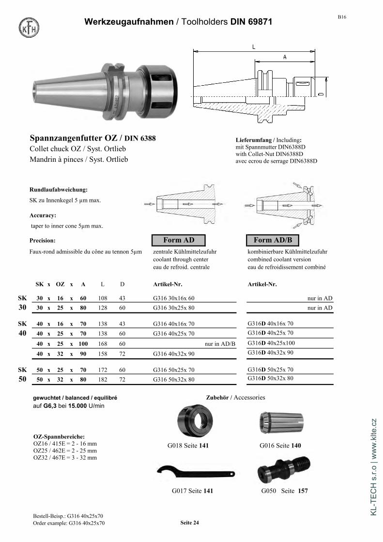
B16Werkzeugaufnahmen / Toolholders DIN 69871
Spannzangenfutter OZ / DIN 6388Collet chuck OZ / Syst. OrtliebMandrin à pinces / Syst. Ortlieb
Rundlaufabweichung:
SK zu Innenkegel 5 µm max.
Accuracy:
taper to inner cone 5µm max.
Precision: Form AD Form AD/BFaux-rond admissible du cône au tennon 5µm zentrale Kühlmittelzufuhr kombinierbare Kühlmittelzufuhr
coolant through center combined coolant versioneau de refroid. centrale eau de refroidissement combiné
SK x OZ x A L D Artikel-Nr. Artikel-Nr.
SK 30 x 16 x 60 108 43 G316 30x16x 60 nur in AD30 30 x 25 x 80 128 60 G316 30x25x 80 nur in AD
SK 40 x 16 x 70 138 43 G316 40x16x 70 G316D 40x16x 70
40 40 x 25 x 70 138 60 G316 40x25x 70 G316D 40x25x 70
40 x 25 x 100 168 60 nur in AD/B G316D 40x25x100
40 x 32 x 90 158 72 G316 40x32x 90 G316D 40x32x 90
SK 50 x 25 x 70 172 60 G316 50x25x 70 G316D 50x25x 7050 50 x 32 x 80 182 72 G316 50x32x 80 G316D 50x32x 80
gewuchtet / balanced / equilibré Zubehör / Accessoriesauf G6,3 bei 15.000 U/min
G018 Seite 141 G016 Seite 140
G017 Seite 141 G050 Seite 157
Lieferumfang / Including:mit Spannmutter DIN6388Dwith Collet-Nut DIN6388Davec ecrou de serrage DIN6388D
OZ-Spannbereiche:OZ16 / 415E = 2 - 16 mmOZ25 / 462E = 2 - 25 mmOZ32 / 467E = 3 - 32 mm
Bestell-Beisp.: G316 40x25x70Order example: G316 40x25x70 Seite 24
KL-T
ECH
s.r.
o | w
ww
.klte
.cz

B16 Werkzeugaufnahmen / Toolholders DIN 69871
Gewindeschneid-Schnellwechselfuttermit Längenausgleich auf Zug und Druck
Quick change tapping chuck with compens.
Mandrins de taraudage à changement rapideavec compensation sur extension et compression.
Form A
Artikel-NummerSK x Gr A d D Gewinde Zubehör / Accessories
G317 30 x 1 60 19 38 M3-M12 mit KupplungG317 30 x 2 101 31 55 M8-M20 with clutch
avec coupleurG317 40 x 1 60 19 38 M3-M12 G013 mit Seite 139G317 40 x 2 100 31 55 M8-M20G317 40 x 3 138 48 78 M14-M33
ohne KupplungG317 50 x 1 62 19 38 M3-M12 without clutchG317 50 x 2 83 31 55 M8-M20 sans coupleurG317 50 x 3 133 48 78 M14-M33 G013 ohne Seite 139G317 50 x 4 147 60 98 M22-M48 auf Anfrage
Verwendung: Zur Aufnahme von Schnellwechseleinsätzen für Gewindebohrer.Längenausgleich auf Zug und DruckAusführung mit Kugelführungsbuchse
Usage: For mounting quick change tapping colletsWith length compensation on tension and compressionVersion with ball retainer
Utilisation: Pour adaptateurs de taraudage à changement rapideAvec compensation de longueur sur extension et compressionVersion comprenant douille de glissière à billes
Ausgleichsweg auf Zug und Druck Tabelle mit Gewindebohrer-Schaftmaßen siehe S.138Größe 1: je 9 mm Dimensions of tap-shafts see page 138Größe 2: je 15 mm Tableau avec dimensions de queues de tarauds page 7Größe 3: je 24 mm
Bestell-Beisp.: G317 40x1Seite 25
KL-T
ECH
s.r.
o | w
ww
.klte
.cz

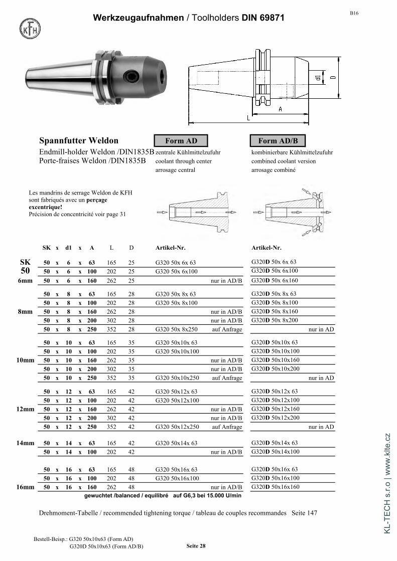
B16Werkzeugaufnahmen / Toolholders DIN 69871
Spannfutter Weldon Form AD Form AD/BEndmill-holder Weldon /DIN1835B zentrale Kühlmittelzufuhr kombinierbare KühlmittelzufuhrMandrins de serrage Weldon coolant through center combined coolant version
arrosage central arrosage combiné
SK x d1 x A L D Artikel-Nr. Artikel-Nr.
SK 30 x 6 x 50 98 25 G320 30x 6x 50 nur in AD30 30 x 8 x 50 98 28 G320 30x 8x 50 nur in AD
30 x 10 x 50 98 35 G320 30x10x 50 nur in AD30 x 12 x 50 98 42 G320 30x12x 50 nur in AD30 x 14 x 50 98 42 G320 30x14x 50 nur in AD30 x 16 x 63 111 48 G320 30x16x 63 nur in AD30 x 18 x 63 111 48 G320 30x18x63 nur in AD30 x 20 x 63 111 52 G320 30x20x 63 nur in AD
SK 40 x 6 x 50 118 25 G320 40x 6x 50 G320D 40x 6x 5040 40 x 6 x 100 168 25 G320 40x 6x100 G320D 40x 6x100
40 x 6 x 160 228 25 nur in AD/B G320D 40x 6x1606mm 40 x 6 x 200 268 25 nur in AD/B G320D 40x 6x200
40 x 8 x 50 118 28 G320 40x 8x 50 G320D 40x 8x 5040 x 8 x 100 168 28 G320 40x 8x100 G320D 40x 8x100
8mm 40 x 8 x 160 228 28 nur in AD/B G320D 40x 8x16040 x 8 x 200 268 28 nur in AD/B G320D 40x 8x20040 x 8 x 250 318 28 G320 40x 8x250 auf Anfrage nur in AD
40 x 10 x 50 118 35 G320 40x10x 50 G320D 40x10x 5040 x 10 x 100 168 35 G320 40x10x100 G320D 40x10x100
10mm 40 x 10 x 160 228 35 nur in AD/B G320D 40x10x16040 x 10 x 200 268 35 nur in AD/B G320D 40x10x20040 x 10 x 250 318 35 G320 40x10x250 auf Anfrage nur in AD
Drehmoment-Tabelle / recommended tightening torque / tableau de couples recommandes Seite 147
Die KFH Weldon-Spannfutterwerden mit
EXZENTRISCHER Bohrunggefertigt !
Rundlaufabweichung siehe Seite 31
Bestell-Beisp.: G320 40x10x50 (Form AD)G320D 40x10x50 (Form AD/B) Seite 26
KL-T
ECH
s.r.
o | w
ww
.klte
.cz

B16 Werkzeugaufnahmen / Toolholders DIN 69871
Spannfutter Weldon Form AD Form AD/BEndmill-holder Weldon /DIN1835B zentrale Kühlmittelzufuhr kombinierbare Kühlmittelzufuhr
Porte-fraise Weldon /DIN1835B coolant through center combined coolant versionarrosage central arrosage combiné
SK x d1 x A L D Artikel-Nr. Artikel-Nr.
SK 40 x 12 x 50 118 42 G320 40x12x 50 G320D 40x12x 5040 40 x 12 x 100 168 42 G320 40x12x100 G320D 40x12x100
40 x 12 x 160 228 42 nur in AD/B G320D 40x12x16012mm 40 x 12 x 200 268 42 nur in AD/B G320D 40x12x200
40 x 12 x 250 318 42 G320 40x12x250 auf Anfrage nur in AD
40 x 14 x 50 118 42 G320 40x14x 50 G320D 40x14x 5014mm 40 x 14 x 100 168 42 nur in AD/B G320D 40x14x100
40 x 14 x 160 228 42 nur in AD/B G320D 40x14x160 auf Anfrage40 x 14 x 200 268 42 nur in AD/B G320D 40x14x200 auf Anfrage
40 x 16 x 35 103 48 G320 40x16x 35 nur in AD40 x 16 x 63 131 48 G320 40x16x 63 G320D 40x16x 63
16mm 40 x 16 x 100 168 48 G320 40x16x100 G320D 40x16x10040 x 16 x 160 228 48 nur in AD/B G320D 40x16x16040 x 16 x 200 268 48 nur in AD/B G320D 40x16x20040 x 16 x 250 318 48 G320 40x16x250 auf Anfrage nur in AD
40 x 18 x 63 131 48 G320 40x18x 63 G320D 40x18x 6318mm 40 x 18 x 100 168 48 nur in AD/B G320D 40x18x100
40 x 18 x 160 228 48 nur in AD/B G320D 40x18x160 auf Anfrage40 x 18 x 200 268 48 nur in AD/B G320D 40x18x200 auf Anfrage
40 x 20 x 35 103 44,45 G320 40x20x 35 G320D 40x20x 3520mm 40 x 20 x 63 131 52 G320 40x20x 63 G320D 40x20x 63
40 x 20 x 100 168 52 G320 40x20x100 G320D 40x20x10040 x 20 x 160 228 52 nur in AD/B G320D 40x20x16040 x 20 x 200 268 52 nur in AD/B G320D 40x20x20040 x 20 x 250 318 52 G320 40x20x250 auf Anfrage nur in AD
22mm 40 x 22 x 63 131 52 nur in AD/B G320D 40x22x 63
40 x 25 x 35 103 44,45 G320 40x25x 35 G320D 40x25x 3525mm 40 x 25 x 100 168 63 G320 40x25x100 G320D 40x25x100
40 x 25 x 160 228 63 nur in AD/B G320D 40x25x16040 x 25 x 200 268 63 nur in AD/B G320D 40x25x20040 x 25 x 250 318 63 G320 40x25x250 auf Anfrage nur in AD
40 x 32 x 63 131 50 nur in AD/B G320D 40x32x 6332mm 40 x 32 x 100 168 70 G320 40x32x100 G320D 40x32x100
40 x 32 x 160 228 70 nur in AD/B G320D 40x32x16040 x 32 x 200 268 70 nur in AD/B G320D 40x32x200
40mm 40 x 40 x 120 188 80 G320 40x40x120 G320D 40x40x120
KFH produces Weldon Holderswith excentric bore !Run-out information on page 31
Bestell-Beisp.: G320 40x14x50 (Form AD)G320D 40x14x50 (Form AD/B) Seite 27
KL-T
ECH
s.r.
o | w
ww
.klte
.cz
B16Werkzeugaufnahmen / Toolholders DIN 69871
Spannfutter Weldon Form AD Form AD/BEndmill-holder Weldon /DIN1835Bzentrale Kühlmittelzufuhr kombinierbare KühlmittelzufuhrPorte-fraises Weldon /DIN1835B coolant through center combined coolant version
arrosage central arrosage combiné
SK x d1 x A L D Artikel-Nr. Artikel-Nr.
SK 50 x 6 x 63 165 25 G320 50x 6x 63 G320D 50x 6x 6350 50 x 6 x 100 202 25 G320 50x 6x100 G320D 50x 6x1006mm 50 x 6 x 160 262 25 nur in AD/B G320D 50x 6x160
50 x 8 x 63 165 28 G320 50x 8x 63 G320D 50x 8x 6350 x 8 x 100 202 28 G320 50x 8x100 G320D 50x 8x100
8mm 50 x 8 x 160 262 28 nur in AD/B G320D 50x 8x16050 x 8 x 200 302 28 nur in AD/B G320D 50x 8x20050 x 8 x 250 352 28 G320 50x 8x250 auf Anfrage nur in AD
50 x 10 x 63 165 35 G320 50x10x 63 G320D 50x10x 6350 x 10 x 100 202 35 G320 50x10x100 G320D 50x10x100
10mm 50 x 10 x 160 262 35 nur in AD/B G320D 50x10x16050 x 10 x 200 302 35 nur in AD/B G320D 50x10x20050 x 10 x 250 352 35 G320 50x10x250 auf Anfrage nur in AD
50 x 12 x 63 165 42 G320 50x12x 63 G320D 50x12x 6350 x 12 x 100 202 42 G320 50x12x100 G320D 50x12x100
12mm 50 x 12 x 160 262 42 nur in AD/B G320D 50x12x16050 x 12 x 200 302 42 nur in AD/B G320D 50x12x20050 x 12 x 250 352 42 G320 50x12x250 auf Anfrage nur in AD
14mm 50 x 14 x 63 165 42 G320 50x14x 63 G320D 50x14x 6350 x 14 x 100 202 42 nur in AD/B G320D 50x14x100
50 x 16 x 63 165 48 G320 50x16x 63 G320D 50x16x 6350 x 16 x 100 202 48 G320 50x16x100 G320D 50x16x100
16mm 50 x 16 x 160 262 48 nur in AD/B G320D 50x16x160gewuchtet /balanced / equilibré auf G6,3 bei 15.000 U/min
Drehmoment-Tabelle / recommended tightening torque / tableau de couples recommandes Seite 147
Les mandrins de serrage Weldon de KFHsont fabriqués avec un perçageexcentrique!Précision de concentricité voir page 31
Bestell-Beisp.: G320 50x10x63 (Form AD)G320D 50x10x63 (Form AD/B) Seite 28
KL-T
ECH
s.r.
o | w
ww
.klte
.cz
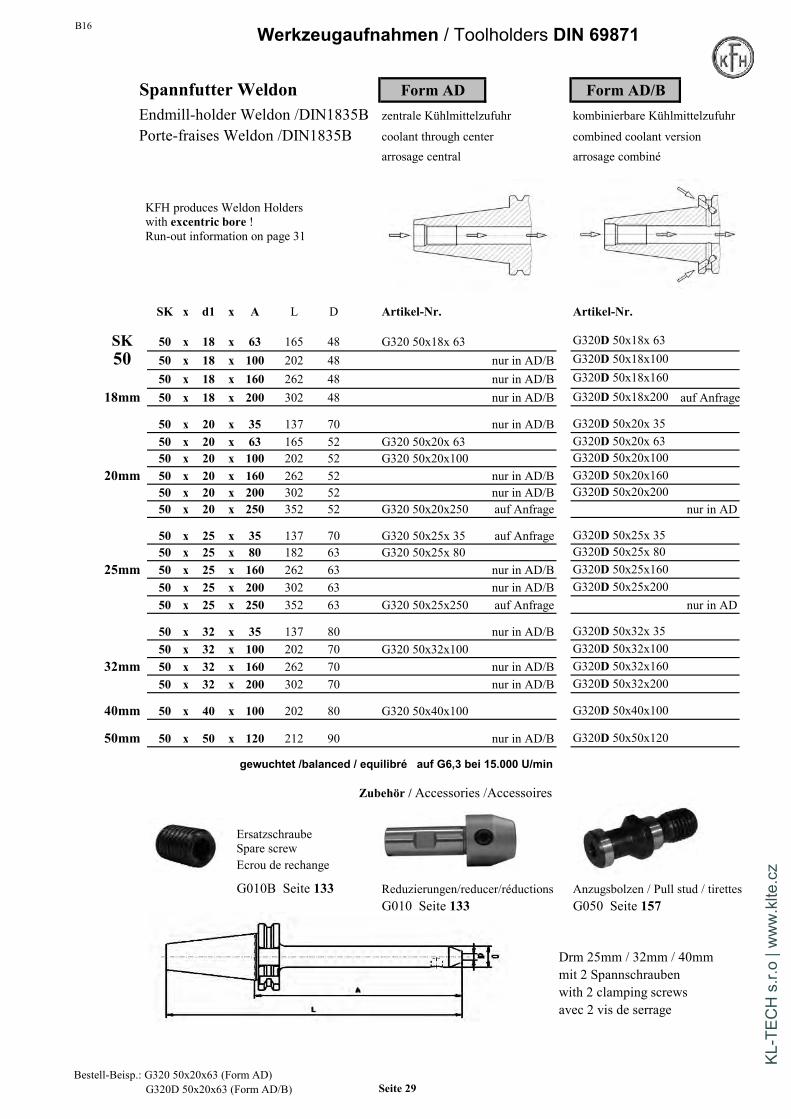
B16 Werkzeugaufnahmen / Toolholders DIN 69871
Spannfutter Weldon Form AD Form AD/BEndmill-holder Weldon /DIN1835B zentrale Kühlmittelzufuhr kombinierbare Kühlmittelzufuhr
Porte-fraises Weldon /DIN1835B coolant through center combined coolant versionarrosage central arrosage combiné
SK x d1 x A L D Artikel-Nr. Artikel-Nr.
SK 50 x 18 x 63 165 48 G320 50x18x 63 G320D 50x18x 6350 50 x 18 x 100 202 48 nur in AD/B G320D 50x18x100
50 x 18 x 160 262 48 nur in AD/B G320D 50x18x16018mm 50 x 18 x 200 302 48 nur in AD/B G320D 50x18x200 auf Anfrage
50 x 20 x 35 137 70 nur in AD/B G320D 50x20x 3550 x 20 x 63 165 52 G320 50x20x 63 G320D 50x20x 6350 x 20 x 100 202 52 G320 50x20x100 G320D 50x20x100
20mm 50 x 20 x 160 262 52 nur in AD/B G320D 50x20x16050 x 20 x 200 302 52 nur in AD/B G320D 50x20x20050 x 20 x 250 352 52 G320 50x20x250 auf Anfrage nur in AD
50 x 25 x 35 137 70 G320 50x25x 35 auf Anfrage G320D 50x25x 3550 x 25 x 80 182 63 G320 50x25x 80 G320D 50x25x 80
25mm 50 x 25 x 160 262 63 nur in AD/B G320D 50x25x16050 x 25 x 200 302 63 nur in AD/B G320D 50x25x20050 x 25 x 250 352 63 G320 50x25x250 auf Anfrage nur in AD
50 x 32 x 35 137 80 nur in AD/B G320D 50x32x 3550 x 32 x 100 202 70 G320 50x32x100 G320D 50x32x100
32mm 50 x 32 x 160 262 70 nur in AD/B G320D 50x32x16050 x 32 x 200 302 70 nur in AD/B G320D 50x32x200
40mm 50 x 40 x 100 202 80 G320 50x40x100 G320D 50x40x100
50mm 50 x 50 x 120 212 90 nur in AD/B G320D 50x50x120
gewuchtet /balanced / equilibré auf G6,3 bei 15.000 U/min
Zubehör / Accessories /Accessoires
ErsatzschraubeSpare screwEcrou de rechange
G010B Seite 133 Reduzierungen/reducer/réductions Anzugsbolzen / Pull stud / tirettesG010 Seite 133 G050 Seite 157
Drm 25mm / 32mm / 40mmmit 2 Spannschraubenwith 2 clamping screwsavec 2 vis de serrage
KFH produces Weldon Holderswith excentric bore !Run-out information on page 31
Bestell-Beisp.: G320 50x20x63 (Form AD)G320D 50x20x63 (Form AD/B) Seite 29
KL-T
ECH
s.r.
o | w
ww
.klte
.cz
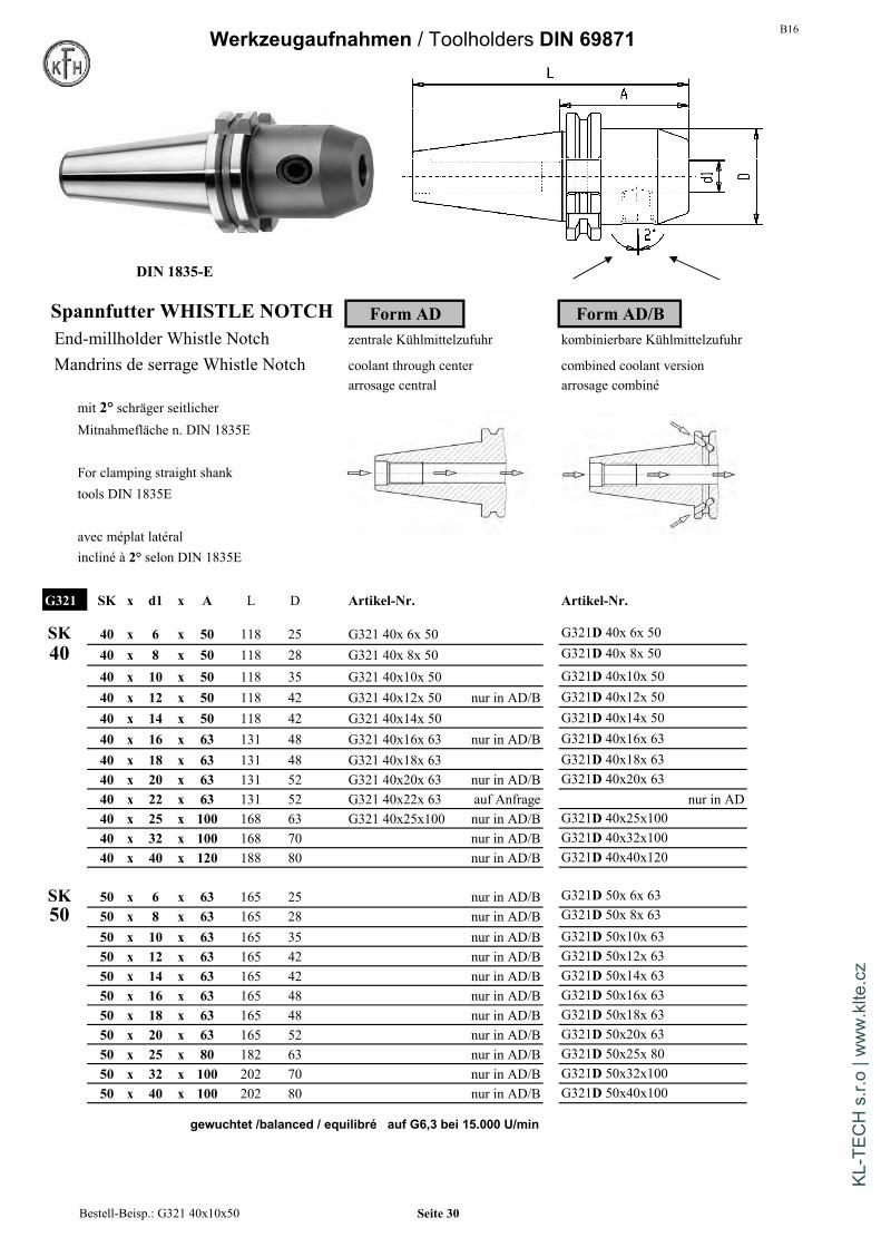
B16Werkzeugaufnahmen / Toolholders DIN 69871
DIN 1835-E
Spannfutter WHISTLE NOTCH Form AD Form AD/BEnd-millholder Whistle Notch zentrale Kühlmittelzufuhr kombinierbare Kühlmittelzufuhr
Mandrins de serrage Whistle Notch coolant through center combined coolant versionarrosage central arrosage combiné
mit 2° schräger seitlicherMitnahmefläche n. DIN 1835E
For clamping straight shanktools DIN 1835E
avec méplat latéralincliné à 2° selon DIN 1835E
G321 SK x d1 x A L D Artikel-Nr. Artikel-Nr.
SK 40 x 6 x 50 118 25 G321 40x 6x 50 G321D 40x 6x 5040 40 x 8 x 50 118 28 G321 40x 8x 50 G321D 40x 8x 50
40 x 10 x 50 118 35 G321 40x10x 50 G321D 40x10x 5040 x 12 x 50 118 42 G321 40x12x 50 nur in AD/B G321D 40x12x 5040 x 14 x 50 118 42 G321 40x14x 50 G321D 40x14x 5040 x 16 x 63 131 48 G321 40x16x 63 nur in AD/B G321D 40x16x 6340 x 18 x 63 131 48 G321 40x18x 63 G321D 40x18x 6340 x 20 x 63 131 52 G321 40x20x 63 nur in AD/B G321D 40x20x 6340 x 22 x 63 131 52 G321 40x22x 63 auf Anfrage nur in AD40 x 25 x 100 168 63 G321 40x25x100 nur in AD/B G321D 40x25x10040 x 32 x 100 168 70 nur in AD/B G321D 40x32x10040 x 40 x 120 188 80 nur in AD/B G321D 40x40x120
SK 50 x 6 x 63 165 25 nur in AD/B G321D 50x 6x 6350 50 x 8 x 63 165 28 nur in AD/B G321D 50x 8x 63
50 x 10 x 63 165 35 nur in AD/B G321D 50x10x 6350 x 12 x 63 165 42 nur in AD/B G321D 50x12x 6350 x 14 x 63 165 42 nur in AD/B G321D 50x14x 6350 x 16 x 63 165 48 nur in AD/B G321D 50x16x 6350 x 18 x 63 165 48 nur in AD/B G321D 50x18x 6350 x 20 x 63 165 52 nur in AD/B G321D 50x20x 6350 x 25 x 80 182 63 nur in AD/B G321D 50x25x 8050 x 32 x 100 202 70 nur in AD/B G321D 50x32x10050 x 40 x 100 202 80 nur in AD/B G321D 50x40x100
gewuchtet /balanced / equilibré auf G6,3 bei 15.000 U/min
Bestell-Beisp.: G321 40x10x50 Seite 30
KL-T
ECH
s.r.
o | w
ww
.klte
.cz

B16
Drehmoment-Tabelle für Spannfutter Weldon siehe Seite 147
Recommended tightening torque for Endmillholders Weldon => page 147
Tableau de couples recommandes pour mandrins de serrage Weldon => page 147
Exzentrische Bohrung beiSpannfutter SystemWeldon nach DIN1835-B
Die KFH Weldon-Spannfutter werden mit exzentrischer Bohrunggefertigt, um das "Aus-der-Mitte-Drücken" durch die radialeSpannschraube auszugleichen.
Es wird eine hohe Rundlaufgenauigkeit von max. 15µm bei 3 x dbei eingespanntem Schaft erreicht.
Achtung - Aufgrund der exzentrischen Bohrung darfeine Rundlaufprüfung nur bei eingespanntem Schaftbei 3xd und nicht direkt in die Bohrung erfolgen.
=> dies ermöglicht maßgenaueres Bearbeitenbei längeren Standzeiten der Fräser.
Excentric bore atSidelock / Weldon Holders according DIN1835B
KFH produces all the Sidelock / Weldon Holders bores excentric to compensate for theclamping screw pushing the tool off center.Accuracy: 15 µmmax. at 3 x d.
Advantages:1. better surface finish - reduced vibration - longer spindle life2. longer " cutting tool " life - reduced tooling / manufacturing costs
Attention - due to the excentric grinding of the bores, the runout can only be checked by inserting a qualified test mandrel. Donot measure bore.
Percage excentrique sur lesmandrins de serrage systeme Weldon selon DIN1835B
Les mandrins de serrage Weldon KFH sont fabriqués avec un perçage excentrique afinde compenser le décentrage de l'outil par la vis de serrage.Avec le mandrin de test, nousobtenons une haute précision de concentricité avec un défaut de maxi. 15µm à 3 x d.
=> Ceci permet un usinage plus précis tout en augmentant la durée de vie des fraises.
Attention - du fait du perçage excentrique, une vérification dela concentricité ne doit être effectuée qu'avec un mandrin de testà 3 x d et non pas directement dans le perçage.
Seite 31
KL-T
ECH
s.r.
o | w
ww
.klte
.cz
B16Werkzeugaufnahmen / Toolholders DIN 69871
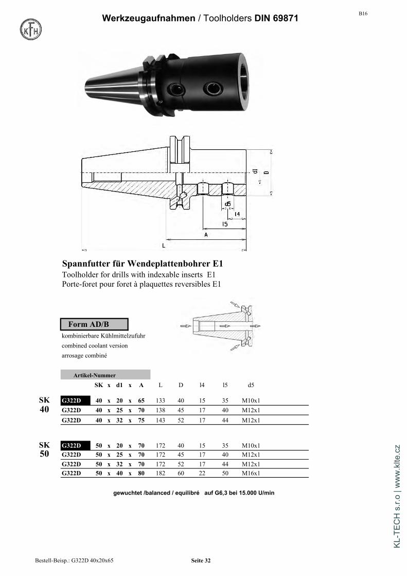
Spannfutter für Wendeplattenbohrer E1Toolholder for drills with indexable inserts E1Porte-foret pour foret à plaquettes reversibles E1
Form AD/Bkombinierbare Kühlmittelzufuhrcombined coolant versionarrosage combiné
Artikel-Nummer
SK x d1 x A L D l4 l5 d5
SK G322D 40 x 20 x 65 133 40 15 35 M10x140 G322D 40 x 25 x 70 138 45 17 40 M12x1
G322D 40 x 32 x 75 143 52 17 44 M12x1
SK G322D 50 x 20 x 70 172 40 15 35 M10x150 G322D 50 x 25 x 70 172 45 17 40 M12x1
G322D 50 x 32 x 70 172 52 17 44 M12x1G322D 50 x 40 x 80 182 60 22 50 M16x1
gewuchtet /balanced / equilibré auf G6,3 bei 15.000 U/min
Bestell-Beisp.: G322D 40x20x65 Seite 32
KL-T
ECH
s.r.
o | w
ww
.klte
.cz
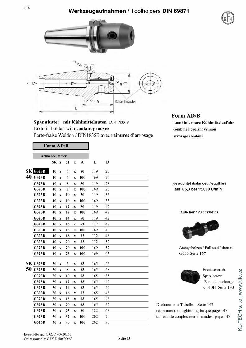
B16 Werkzeugaufnahmen / Toolholders DIN 69871
Form AD/BSpannfutter mit Kühlmittelnuten DIN 1835-B kombinierbare KühlmittelzufuhrEndmill holder with coolant grooves combined coolant versionPorte-fraise Weldon / DIN1835B avec rainures d'arrosage arrosage combiné
Form AD/B
Artikel-Nummer
SK x d1 x A L D
SK G323D 40 x 6 x 50 119 2540 G323D 40 x 6 x 100 169 25
G323D 40 x 8 x 50 119 28 gewuchtet /balanced / equilibréG323D 40 x 8 x 100 169 28 auf G6,3 bei 15.000 U/minG323D 40 x 10 x 50 119 35G323D 40 x 10 x 100 169 35G323D 40 x 12 x 50 119 42G323D 40 x 12 x 100 169 42 Zubehör / AccessoriesG323D 40 x 14 x 50 119 42G323D 40 x 16 x 63 132 48G323D 40 x 16 x 100 169 48G323D 40 x 18 x 63 132 48G323D 40 x 20 x 63 132 52G323D 40 x 20 x 100 169 52 Anzugsbolzen / Pull stud / tirettesG323D 40 x 25 x 100 169 63 G050 Seite 157
SK G323D 50 x 6 x 63 165 2550 G323D 50 x 8 x 63 165 28 Ersatzschraube
G323D 50 x 10 x 63 165 35 Spare screwG323D 50 x 12 x 63 165 42 Ecrou de rechangeG323D 50 x 14 x 63 165 42 G010B Seite 133G323D 50 x 16 x 63 165 48G323D 50 x 18 x 63 165 48G323D 50 x 20 x 63 165 52 Drehmoment-Tabelle Seite 147G323D 50 x 25 x 80 182 63 recommended tightening torque page 147G323D 50 x 32 x 100 202 70 tableau de couples recommandes page 147G323D 50 x 40 x 100 202 90
Bestell-Beisp.: G323D 40x20x63Order example: G323D 40x20x63 Seite 33
KL-T
ECH
s.r.
o | w
ww
.klte
.cz

B16Werkzeugaufnahmen / Toolholders DIN 69871
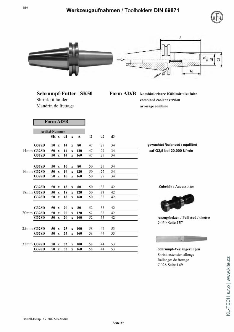
Schrumpf-Futter SK40 Form AD/B kombinierbare KühlmittelzufuhrShrink fit holder combined coolant version
Mandrin de frettage arrosage combiné
Form AD/B
Artikel-NummerSK x d1 x A l2 d2 d3
G328D 40 x 3 x 80 - 12 20 gewuchtet /balanced / equilibré3mm G328D 40 x 3 x 120 - 12 20 auf G2,5 bei 20.000 U/min
G328D 40 x 3 x 160 - 12 20
G328D 40 x 4 x 80 - 15 254mm G328D 40 x 4 x 120 - 15 25
G328D 40 x 4 x 160 - 15 25
G328D 40 x 5 x 80 - 15 255mm G328D 40 x 5 x 120 - 15 25
G328D 40 x 5 x 160 - 15 25Mindesteinspanntiefen :
G328D 40 x 6 x 80 36 20 276mm G328D 40 x 6 x 120 36 21 27 Bohrungsdurchmesser 6 mm = 26 mm
G328D 40 x 6 x 160 36 21 27 Bohrungsdurchmesser 8 mm = 26 mmBohrungsdurchmesser 10 mm = 31 mm
G328D 40 x 8 x 80 36 20 27 Bohrungsdurchmesser 12 mm = 37 mm8mm G328D 40 x 8 x 120 36 21 27 Bohrungsdurchmesser 14 mm = 37 mm
G328D 40 x 8 x 160 36 21 27 Bohrungsdurchmesser 16 mm = 40 mmBohrungsdurchmesser 18 mm = 40 mm
G328D 40 x 10 x 80 42 24 32 Bohrungsdurchmesser 20 mm = 42 mm10mm G328D 40 x 10 x 120 42 24 32 Bohrungsdurchmesser 25 mm = 48 mm
G328D 40 x 10 x 160 42 24 32 Bohrungsdurchmesser 32 mm = 52 mm
G328D 40 x 12 x 80 47 24 3212mm G328D 40 x 12 x 120 47 24 32
G328D 40 x 12 x 160 47 24 32
Bestell-Beisp.: G328D 40x12x80Seite 34
KL-T
ECH
s.r.
o | w
ww
.klte
.cz

B16 Werkzeugaufnahmen / Toolholders DIN 69871
Schrumpf-Futter SK40 Form AD/B kombinierbare KühlmittelzufuhrShrink fit holder combined coolant version
Mandrin de frettage arrosage combiné
Form AD/B
Artikel-NummerSK x d1 x A l2 d2 d3
G328D 40 x 14 x 80 47 27 34 gewuchtet /balanced / equilibré
14mm G328D 40 x 14 x 120 27 34 auf G2,5 bei 20.000 U/minG328D 40 x 14 x 160 47 27 34
G328D 40 x 16 x 80 50 27 3416mm G328D 40 x 16 x 120 50 27 34
G328D 40 x 16 x 160 50 27 34
G328D 40 x 18 x 80 50 33 42 Zubehör / Accessories18mm G328D 40 x 18 x 120 50 33 42
G328D 40 x 18 x 160 50 33 42
G328D 40 x 20 x 80 52 33 4220mm G328D 40 x 20 x 120 52 33 42
G328D 40 x 20 x 160 52 33 42 Anzugsbolzen / Pull stud / tirettesG050 Seite 157
25mm G328D 40 x 25 x 100 58 44 53G328D 40 x 25 x 160 58 44 53
32mm G328D 40 x 32 x 100 58 44 53G328D 40 x 32 x 160 58 44 53
Schrumpf-VerlängerungenShrink extension allongeRallonges de frettageG028 Seite 149
Bestell-Beisp.: G328D 40x20x80Seite 35
KL-T
ECH
s.r.
o | w
ww
.klte
.cz

B16Werkzeugaufnahmen / Toolholders DIN 69871
Schrumpf-Futter SK50 Form AD/B kombinierbare KühlmittelzufuhrShrink fit holder combined coolant version
Mandrin de frettage arrosage combiné
Form AD/B
Artikel-NummerSK x d1 x A l2 d2 d3
G328D 50 x 3 x 80 - 10 20 gewuchtet /balanced / equilibré3mm G328D 50 x 3 x 120 - 10 20 Anfrage auf G2,5 bei 20.000 U/min
G328D 50 x 3 x 160 - 10 20 Anfrage
G328D 50 x 4 x 80 - 15 254mm G328D 50 x 4 x 120 - 15 25 Anfrage
G328D 50 x 4 x 160 - 15 25 Anfrage
G328D 50 x 5 x 80 - 15 255mm G328D 50 x 5 x 120 - 15 25 Anfrage
G328D 50 x 5 x 160 - 15 25 Anfrage
G328D 50 x 6 x 80 36 21 276mm G328D 50 x 6 x 120 36 21 27 Mindesteinspanntiefen :
G328D 50 x 6 x 160 36 21 27 Minimum clamping depthProfondeurs de serrage mini. :
G328D 50 x 8 x 80 36 21 278mm G328D 50 x 8 x 120 36 21 27 Bohrungsdurchmesser 6 mm = 26 mm
G328D 50 x 8 x 160 36 21 27 Bohrungsdurchmesser 8 mm = 26 mmBohrungsdurchmesser 10 mm = 31 mm
G328D 50 x 10 x 80 42 24 32 Bohrungsdurchmesser 12 mm = 37 mm10mm G328D 50 x 10 x 120 42 24 32 Bohrungsdurchmesser 14 mm = 37 mm
G328D 50 x 10 x 160 42 24 32 Bohrungsdurchmesser 16 mm = 40 mmBohrungsdurchmesser 18 mm = 40 mm
G328D 50 x 12 x 80 47 24 32 Bohrungsdurchmesser 20 mm = 42 mm12mm G328D 50 x 12 x 120 47 24 32 Bohrungsdurchmesser 25 mm = 48 mm
G328D 50 x 12 x 160 47 24 32 Bohrungsdurchmesser 32 mm = 52 mm
Bestell-Beisp.: G328D 50x 6x80Seite 36
KL-T
ECH
s.r.
o | w
ww
.klte
.cz
B16 Werkzeugaufnahmen / Toolholders DIN 69871
Schrumpf-Futter SK50 Form AD/B kombinierbare KühlmittelzufuhrShrink fit holder combined coolant version
Mandrin de frettage arrosage combiné
Form AD/B
Artikel-NummerSK x d1 x A l2 d2 d3
G328D 50 x 14 x 80 47 27 34 gewuchtet /balanced / equilibré
14mm G328D 50 x 14 x 120 47 27 34 auf G2,5 bei 20.000 U/minG328D 50 x 14 x 160 47 27 34
G328D 50 x 16 x 80 50 27 3416mm G328D 50 x 16 x 120 50 27 34
G328D 50 x 16 x 160 50 27 34
G328D 50 x 18 x 80 50 33 42 Zubehör / Accessories18mm G328D 50 x 18 x 120 50 33 42
G328D 50 x 18 x 160 50 33 42
G328D 50 x 20 x 80 52 33 4220mm G328D 50 x 20 x 120 52 33 42
G328D 50 x 20 x 160 52 33 42 Anzugsbolzen / Pull stud / tirettesG050 Seite 157
25mm G328D 50 x 25 x 100 58 44 53G328D 50 x 25 x 160 58 44 53
32mm G328D 50 x 32 x 100 58 44 53G328D 50 x 32 x 160 58 44 53 Schrumpf-Verlängerungen
Shrink extension allongeRallonges de frettageG028 Seite 149
Bestell-Beisp.: G328D 50x20x80Seite 37
KL-T
ECH
s.r.
o | w
ww
.klte
.cz

B16Werkzeugaufnahmen / Toolholders DIN 69871
Bohrfutteraufnahmen DIN238 Standard-BohrfutterTaper shafts DIN238 Standard Drill chuckCônes d'emmanchement DIN238 Mandrin de percage standard
Mit Schlüssel / with wrench / avec clé de serrageZur Aufnahme von Bohrfuttern mit InnenkonusFor mounting drill chucks with inner conePour la fixation de mandrin avec cone interieur
Rechts-Lauf geeignetArtikel-Nummer Suitable for right-hand rotation
SK x D A L Pour rotation seulement droite
G330 30 x 12 40 108 auf Anfrage Rundlaufabweich.max 50µm bei 3 x d1G330 30 x 16 25 112 Max runout: 50µm
Faux-rond admissible: 50µm max.
G330 40 x 12 25 112G330 40 x 16 25 117 Artikel-NummerG330 40 x 18 35 135 SK x A L DG330 40 x 22 40 149 auf Anfrage
G332 40 x 13 87 156 51G330 50 x 16 25 151 G332 40 x 16 110 179 57G330 50 x 18 25 159G330 50 x 22 40 183 auf Anfrage G332 50 x 13 86 188 51
G332 50 x 16 90 192 57
Zubehör / Accessories Zubehör / Accessories
Anzugsbolzen / Pull studAufsteck-Bohrkopf / drill-chuck-head Seite / page 157Seite / page 153
Bestell-Beisp.: G332 50x16Order example: Seite 38
KL-T
ECH
s.r.
o | w
ww
.klte
.cz

B16 Werkzeugaufnahmen / Toolholders DIN 69871
Präzisions-Bohrfutter Hoch-Präzisions-BohrfutterPrecision Drill chuck High-precision Drill chuckMandrin de percage precision Mandrin de percage haute-precision
Mit Schlüssel / with wrench / avec clé de serrage Mit Schlüssel / with wrench / avec clé de serrage
Rechts-Linkslauf geeignet Rechts-Linkslauf geeignetSuitable for right-hand and left-hand rotation Suitable for right-hand and left-hand rotationPour rotation gauche-droite Pour rotation gauche-droite
Rundlaufabweich.max 35µm bei 3 x d1 Rundlaufabweich.max 20µm bei 3 x d1Max runout: 35µm Max runout: 20µmFaux-rond admissible: 35µm max. Faux-rond admissible: 20µm max.
Artikel-Nummer Form AD/B Artikel-Nummer Form ASK x d1 A D Bereich SK x d1 A D Bereich
G333D 40 x 13 95 50 1-13 G334 30 x 8 70 36 0,3-8G333D 40 x 16 100 50 2,5-16 G334 30 x 13 111 50 0,5-13
G333D 50 x 13 106 50 1-13 G334 40 x 8 76 36 0,3-8G333D 50 x 16 111 50 2,5-16 G334 40 x 13 90 50 0,5-13
G334 40 x 16 95 57 2,5-16
Präzisionsbohrfutter / Precision drill chuck G334 50 x 13 106 50Weitere techn. Informationen / Anzugsmomente S. 75 G334 50 x 16 111 57Further technical information / tightening torque page 75Information technique / couple de serrage autorise page 75 Artikel-Nummer Form AD/B
SK x d1 A DG334D 40 x 8 76 36 0,3-8G334D 40 x 13 95 50 0,5-13
Hoch-Präzisionsbohrfutter / High-Precision drill chuck G334D 40 x 16 100 57 2,5-16Weitere techn. Informationen / Anzugsmomente S.137Further technical information / tightening torque page 137 G334D 50 x 13 106 50 0,5-13Information technique / couple de serrage autorise page 43
Bestell-Beisp.: G333D40x13Order example: Seite 39
KL-T
ECH
s.r.
o | w
ww
.klte
.cz
B16
Werkzeugaufnahmen / Toolholders DIN 69871
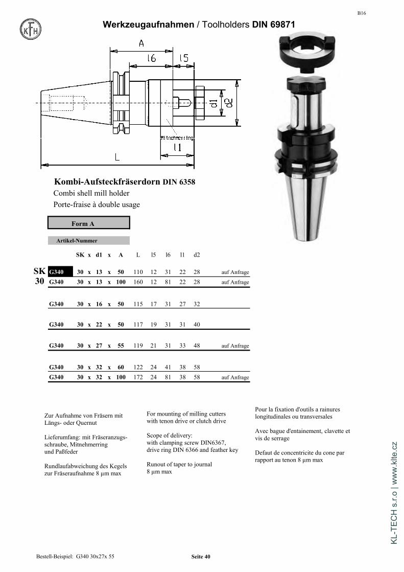
Kombi-Aufsteckfräserdorn DIN 6358Combi shell mill holderPorte-fraise à double usage
Form A
Artikel-Nummer
SK x d1 x A L l5 l6 l1 d2
SK G340 30 x 13 x 50 110 12 31 22 28 auf Anfrage
30 G340 30 x 13 x 100 160 12 81 22 28 auf Anfrage
G340 30 x 16 x 50 115 17 31 27 32
G340 30 x 22 x 50 117 19 31 31 40
G340 30 x 27 x 55 119 21 31 33 48 auf Anfrage
G340 30 x 32 x 60 122 24 41 38 58G340 30 x 32 x 100 172 24 81 38 58 auf Anfrage
Zur Aufnahme von Fräsern mitLängs- oder Quernut
Lieferumfang: mit Fräseranzugs-schraube, Mitnehmerringund Paßfeder
Rundlaufabweichung des Kegelszur Fräseraufnahme 8 µm max
For mounting of milling cutterswith tenon drive or clutch drive
Scope of delivery:with clamping screw DIN6367,drive ring DIN 6366 and feather key
Runout of taper to journal8 µm max
Pour la fixation d'outils a rainureslongitudinales ou transversales
Avec bague d'entainement, clavette etvis de serrage
Defaut de concentricite du cone parrapport au tenon 8 µm max
Bestell-Beispiel: G340 30x27x 55 Seite 40
KL-T
ECH
s.r.
o | w
ww
.klte
.cz

B16 Werkzeugaufnahmen / Toolholders DIN 69871
Kombi-Aufsteckfräserdorn DIN 6358Combi shell mill holderPorte-fraise à double usage
Form A Form AD/BLänge A=200mm auf Anfrage ohne innere Kühlmittelzufuhr kombinierbare KühlmiLength A=200 mm on request without internal coolant supply combined coolant versLongueur A=200mm sur demande sans refroidissement arrosage combiné
SK x d1 x A L l5 l6 l1 d2 Artikel-Nr. Artikel-Nr.
SK 40 x 16 x 55 141 17 36 27 32 G340 40x16x 55 G340D40x16x 55
40 40 x 16 x 100 186 17 81 27 32 G340 40x16x100 G340D40x16x10016mm 40 x 16 x 160 248 17 141 27 32 G340 40x16x160 G340D40x16x160
40 x 22 x 55 143 19 36 31 40 G340 40x22x 55 G340D40x22x 55
22mm 40 x 22 x 100 188 19 81 31 40 G340 40x22x100 G340D40x22x10040 x 22 x 160 248 19 141 31 40 G340 40x22x160 G340D40x22x160
40 x 27 x 62 152 21 43 33 48 G340 40x27x 62 G340D40x27x 62
27mm 40 x 27 x 100 190 21 81 33 48 G340 40x27x100 G340D40x27x10040 x 27 x 160 250 21 141 33 48 G340 40x27x160 G340D40x27x160
40 x 32 x 60/69 152 24 41 38 58 G340 40x32x 60 G340D40x32x 69
32mm 40 x 32 x 100 193 24 81 38 58 G340 40x32x100 G340D40x32x10040 x 32 x 160 253 24 141 38 58 G340 40x32x160 G340D40x32x160
40 x 40 x 60 156 27 41 41 70 G340 40x40x 60 G340D40x40x 60
40mm 40 x 40 x 100 196 27 81 41 70 G340 40x40x100 G340D40x40x10040 x 40 x 160 256 27 141 41 70 G340 40x40x160 G340D40x40x160
For mounting of milling cutterswith tenon drive or clutch drive
Scope of delivery:with clamping screw DIN6367,drive ring DIN 6366 and feather key
Runout of taper to journal8 µm max
Bestell-Beispiel: G340 40x32x100 Seite 41
KL-T
ECH
s.r.
o | w
ww
.klte
.cz

B16Werkzeugaufnahmen / Toolholders DIN 69871
Kombi-Aufsteckfräserdorn DIN 6358Combi shell mill holderPorte-fraise à double usage
Ersatzteile / Spare parts
G040 Seite/ Page 154 G041 Seite/ Page 154
G042 Seite/ Page 154 Form A Form AD/Bohne innere Kühlmittelzufuhr kombinierbare Kühlmittelzufuhr
Länge A=200mm auf Anfrage without internal coolant supply combined coolant versionLength A=200 mm on request sans refroidissement arrosage combiné
SK x d1 x A L l5 l6 l1 d2 Artikel-Nr. Artikel-Nr.
SK 50 x 16 x 55 174 17 36 27 32 G340 50x16x 55 G340D50x16x 55
50 50 x 16 x 100 219 17 81 27 32 G340 50x16x100 G340D50x16x100 Anfrage16mm 50 x 16 x 160 279 17 141 27 32 G340 50x16x160 G340D50x16x160 Anfrage
50 x 22 x 55 176 19 36 31 40 G340 50x22x 55 G340D50x22x 55
22mm 50 x 22 x 100 221 19 81 31 40 G340 50x22x100 G340D50x22x100 Anfrage50 x 22 x 160 281 19 141 31 40 G340 50x22x160 G340D50x22x160 Anfrage
50 x 27 x 55 178 21 36 33 48 G340 50x27x 55 G340D50x27x 55
27mm 50 x 27 x 100 223 21 81 33 48 G340 50x27x100 G340D50x27x100 Anfrage50 x 27 x 160 283 21 141 33 48 G340 50x27x160 G340D50x27x160 Anfrage
50 x 32 x 55 181 24 36 38 58 G340 50x32x 55 G340D50x32x 55
32mm 50 x 32 x 100 226 24 81 38 58 G340 50x32x100 G340D50x32x100 Anfrage50 x 32 x 160 286 24 141 38 58 G340 50x32x160 G340D50x32x160 Anfrage
50 x 40 x 55 184 27 36 41 70 G340 50x40x 55 G340D50x40x 55
40mm 50 x 40 x 100 229 27 81 41 70 G340 50x40x100 G340D50x40x100 Anfrage50 x 40 x 160 289 27 141 41 70 G340 50x40x160 G340D50x40x160 Anfrage
50mm 50 x 50 x 70 207 30 56 46 90 G340 50x50x 70 nur in Form A
Zur Aufnahme von Fräsern mitLängs- oder Quernut
Lieferumfang: mit Fräseranzugs-schraube, Mitnehmerringund Paßfeder
Rundlaufabweichung des Kegelszur Fräseraufnahme 8 µm max
Bestell-Beispiel: G340 50x32x100 Seite 42
KL-T
ECH
s.r.
o | w
ww
.klte
.cz

B16 Technische Information / technical information
CNC-Hoch-Präzisions-BohrfutterArtikelgruppen G134 / G234 / G334 / G434 / G534 / G634
Bezeichnung 08 13 16
Spannbereich 0,3-8 mm 0,5-13 mm 2,5-16 mm DIN2080 Seite 9
Rundlaufabweichung max. 0,02 mm 0,02 mm 0,02 mmbei einem Anzugsmoment von 8 Nm von 15 Nm von 15 Nm
Haltemoment 30 Nm 40 Nm 45 Nmbei einem Anzugsmoment von 10 Nm von 15 Nm von 15 Nm
max.zul.Anzugsmoment 10 Nm 20 Nm 20 Nm S20x2 Seite 17
Haltemoment 80 Nm 90 Nmbei einem Anzugsmoment von 20 Nm von 20 Nm
max.zul. Drehzahl 35.000 min 35.000 min 35.000 minAlle Hochpräzisions-Bohrfutter werden mittels eines im Lieferumfang DIN69871 Seite 39enthaltenen Sechskant-Schlüssels über einen Kegeltrieb gespannt.Für den Einsatz des Bohrfutters ist ein Anzugsmomentvon 8 Nm bzw. 15 Nm ausreichend.Dabei entsteht ein Haltemoment,am gespannten Werkzeug von 30 Nm,40 Nm bzw.45 Nm (Werte gemessen an einem gereinigten Hartmetallstift)Die Bohrfutter sind ungewuchtet für einen Einsatz bis 7000 U/min geeignet. MAS BT Seite 71Für die Anwendung bei Drehzahlen über 7000 U/min müssendie Bohrfutter gegen Aufpreis feingewuchtet werden.Die Bohrfutter sind Rechts- / Linkslauf geeignet
Mandrin de percage haute-precision Morsekegel Seite 83
Groupes de produits G134 / G234 / G334 / G434 / G534 / G634
Tailles 08 13 16
Capacite de serrage 0,3-8 mm 0,5-13 mm 2,5-16 mm
Defaut de concentricite max. 0,02 mm 0,02 mm 0,02 mmavec un couple de serrage of 8 Nm of 15 Nm of 15 Nm HSK Seite 103
Couple d'impulsion 30 Nm 40 Nm 45 Nmavec un couple de serrage of 10 Nm of 15 Nm of 15 Nm
Couple de serrage autorise max. 10 Nm 20 Nm 20 Nm
Couple d'impulsion 80 Nm 90 Nmavec un couple de serrage of 20 Nm of 20 Nm Weldon-Schaft Seite 136
Tours admissible max. 35.000 min 35.000 min 35.000 minTous les mandrins de perçage de précision sont serrés par un engrenage conique latéralau moyen d'une clé 6-pans compris dans la livraison. Pour la mise en place du mandrinde serrage, sur la clé 6-pans un couple de 15Nm est suffisant.Ceci engendre un couple d'impulsion de 30Nm, 40Nm ou 45Nm sur l'outil serré(valeurs mesurées sur une pige carbure nettoyée).Sans équilibrage, les mandrins de perçage peuvent être utilisés jusqu'à 7000 tr/min.Pour des vitesses supérieures à 7000 tr/min., les mandrins de perçage doiventêtre équilibrés fin, moyennant un supplément de prix.Les mandrins de serrage peuvent tourner à droite et à gauche
Seite 43
KL-T
ECH
s.r.
o | w
ww
.klte
.cz

B16Werkzeugaufnahmen / Toolholders DIN 69871
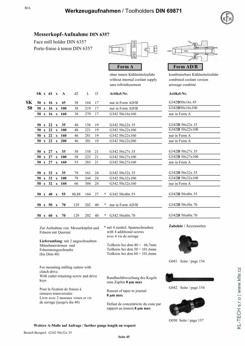
Messerkopf-Aufnahme DIN 6357Face mill holder DIN 6357Porte-fraise à tenon DIN 6357
Form A Form AD/Bohne innere Kühlmittelzufuhr kombinierbare Kühlmittelzufuhrwithout internal coolant supply combined coolant versionsans refroidissement arrosage combiné
SK x d1 x A d2 L l3 Artikel-Nr. Artikel-Nr.
SK 30 16 40 38 105 17 G342 30x16x40 nur in Form A
30 30 22 40 48 107 19 G342 30x22x40 nur in Form A30 27 50 58 119 21 G342 30x27x50 nur in Form A30 32 50 78 122 24 G342 30x32x50 nur in Form A
SK 40 x 16 x 35 40 121 17 G342 40x16x 35 G342D 40x16x 35
40 40 x 16 x 100 38 186 17 G342 40x16x100 G342D 40x16x10040 x 16 x 160 38 246 17 G342 40x16x160 nur in Form A
40 x 22 x 35 44,45 123 19 G342 40x22x 35 G342D 40x22x 3540 x 22 x 50 48 138 19 G342 40x22x 50 G342D 40x22x 5040 x 22 x 100 48 188 19 G342 40x22x100 G342D 40x22x10040 x 22 x 160 48 248 19 G342 40x22x160 nur in Form A
40 x 27 x 35 44,45 125 21 G342 40x27x 35 G342D 40x27x 3540 x 27 x 50 60 140 21 G342 40x27x 50 G342D 40x27x 5040 x 27 x 100 58 190 21 G342 40x27x100 G342D 40x27x10040 x 27 x 160 58 248 21 G342 40x27x160 nur in Form A
40 x 32 x 55 78 148 24 G342 40x32x 55 G342D 40x32x 5540 x 32 x 100 78 193 24 G342 40x32x100 G342D 40x32x100
40 x 40 x 60 88,88 156 27 * G342 40x40x 60 G342D 40x40x 6040 x 40 x 100 88,88 196 27 * G342 40x40x100 Auf Anfrage nur in Form A
Weitere A-Maße auf Anfragefurther gauge length on request
Rundlaufabweichung des Kegelszum Zapfen 8 µm max
Runout of taper to journal8 µm max
Faux-rond admissible du cone autourillon 8 µm max
* mit 4 zusätzl. Spannschraubenwith 4 additional screwsavec 4 vis de serrage
Teilkreis bei drm 40 = 66,7mmTeilkreis bei drm 50 = 101,6mmTeilkreis bei drm 60 = 101,6mm
Bestell-Beispiel: G342 40x32x100Order example: Seite 44
KL-T
ECH
s.r.
o | w
ww
.klte
.cz
B16 Werkzeugaufnahmen / Toolholders DIN 69871
Messerkopf-Aufnahme DIN 6357Face mill holder DIN 6357Porte-fraise à tenon DIN 6357
Form A Form AD/Bohne innere Kühlmittelzufuhr kombinierbare Kühlmittelzufuhrwithout internal coolant supply combined coolant versionsans refroidissement arrosage combiné
SK x d1 x A d2 L l3 Artikel-Nr. Artikel-Nr.
SK 50 x 16 x 45 38 164 17 nur in Form AD/B G342D50x16x 4550 50 x 16 x 100 38 219 17 nur in Form AD/B G342D50x16x100
50 x 16 x 160 38 279 17 G342 50x16x160 nur in Form A
50 x 22 x 35 48 156 19 G342 50x22x 35 G342D 50x22x 3550 x 22 x 100 48 221 19 G342 50x22x100 G342D 50x22x10050 x 22 x 160 46 281 19 G342 50x22x160 nur in Form A50 x 22 x 200 46 301 19 G342 50x22x200 nur in Form A
50 x 27 x 35 58 158 21 G342 50x27x 35 G342D 50x27x 3550 x 27 x 100 58 223 21 G342 50x27x100 G342D 50x27x10050 x 27 x 160 55 283 21 G342 50x27x160 nur in Form A
50 x 32 x 35 78 161 24 G342 50x32x 35 G342D 50x32x 3550 x 32 x 100 78 244 24 G342 50x32x100 G342D 50x32x10050 x 32 x 160 66 304 24 G342 50x32x160 nur in Form A
50 x 40 x 55 88,88 184 27 * G342 50x40x 55 G342D 50x40x 55
50 x 50 x 70 129 202 40 * nur in Form AD/B G342D 50x50x 70
50 x 60 x 70 129 202 40 * G342 50x60x 70 G342D 50x60x 70
Zubehör /Accessories
G041 Seite / page 154
G042 Seite / page 154
G050 Seite / page 157Weitere A-Maße auf Anfrage / further gauge length on request
Zur Aufnahme von Messerköpfen undFräsern mit Quernut
Lieferumfang: mit 2 angeschraubtenMitnehmersteinen undFräseranzugsschraube(bis Drm 40)
For mounting milling cutters withclutch drive.With cutter-retaining-screw and drivekeys
Pour la fixation de fraises àrainures transversalesLivre avec 2 tasseaux visses et visde serrage (jusqu'a dia 40)
* mit 4 zusätzl. Spannschraubenwith 4 additional screwsavec 4 vis de serrage
Teilkreis bei drm 40 = 66,7mmTeilkreis bei drm 50 = 101,6mmTeilkreis bei drm 60 = 101,6mm
Rundlaufabweichung des Kegelszum Zapfen 8 µm max
Runout of taper to journal8 µm max
Defaut de concentricite du cone parrapport au tennon 8 µm max
Bestell-Beispiel: G342 50x32x 35Seite 45
KL-T
ECH
s.r.
o | w
ww
.klte
.cz
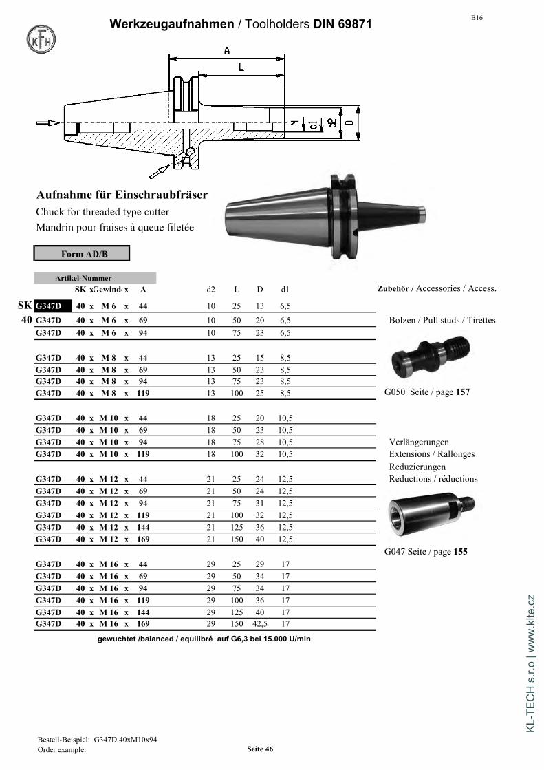
B16Werkzeugaufnahmen / Toolholders DIN 69871
Aufnahme für EinschraubfräserChuck for threaded type cutterMandrin pour fraises à queue filetée
Form AD/B
Artikel-NummerSK xGewindex A d2 L D d1 Zubehör / Accessories / Access.
SK G347D 40 x M 6 x 44 10 25 13 6,5
40 G347D 40 x M 6 x 69 10 50 20 6,5 Bolzen / Pull studs / TirettesG347D 40 x M 6 x 94 10 75 23 6,5
G347D 40 x M 8 x 44 13 25 15 8,5G347D 40 x M 8 x 69 13 50 23 8,5G347D 40 x M 8 x 94 13 75 23 8,5G347D 40 x M 8 x 119 13 100 25 8,5 G050 Seite / page 157
G347D 40 x M 10 x 44 18 25 20 10,5G347D 40 x M 10 x 69 18 50 23 10,5G347D 40 x M 10 x 94 18 75 28 10,5 VerlängerungenG347D 40 x M 10 x 119 18 100 32 10,5 Extensions / Rallonges
ReduzierungenG347D 40 x M 12 x 44 21 25 24 12,5 Reductions / réductionsG347D 40 x M 12 x 69 21 50 24 12,5G347D 40 x M 12 x 94 21 75 31 12,5G347D 40 x M 12 x 119 21 100 32 12,5G347D 40 x M 12 x 144 21 125 36 12,5G347D 40 x M 12 x 169 21 150 40 12,5
G047 Seite / page 155G347D 40 x M 16 x 44 29 25 29 17G347D 40 x M 16 x 69 29 50 34 17G347D 40 x M 16 x 94 29 75 34 17G347D 40 x M 16 x 119 29 100 36 17G347D 40 x M 16 x 144 29 125 40 17G347D 40 x M 16 x 169 29 150 42,5 17
gewuchtet /balanced / equilibré auf G6,3 bei 15.000 U/min
Bestell-Beispiel: G347D 40xM10x94Order example: Seite 46
KL-T
ECH
s.r.
o | w
ww
.klte
.cz
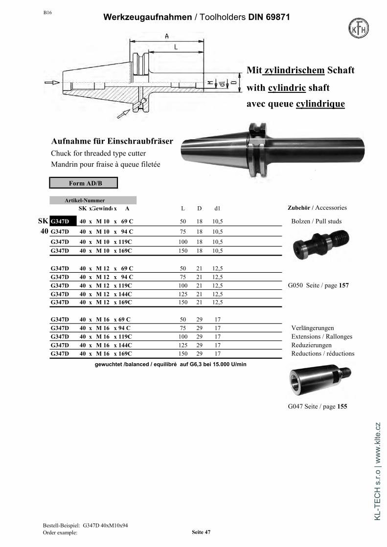
B16 Werkzeugaufnahmen / Toolholders DIN 69871
Mit zylindrischem Schaft
with cylindric shaftavec queue cylindrique
Aufnahme für EinschraubfräserChuck for threaded type cutterMandrin pour fraise à queue filetée
Form AD/B
Artikel-NummerSK xGewindex A L D d1 Zubehör / Accessories
SK G347D 40 x M 10 x 69 C 50 18 10,5 Bolzen / Pull studs40 G347D 40 x M 10 x 94 C 75 18 10,5
G347D 40 x M 10 x 119C 100 18 10,5G347D 40 x M 10 x 169C 150 18 10,5
G347D 40 x M 12 x 69 C 50 21 12,5G347D 40 x M 12 x 94 C 75 21 12,5G347D 40 x M 12 x 119C 100 21 12,5 G050 Seite / page 157G347D 40 x M 12 x 144C 125 21 12,5G347D 40 x M 12 x 169C 150 21 12,5
G347D 40 x M 16 x 69 C 50 29 17G347D 40 x M 16 x 94 C 75 29 17 VerlängerungenG347D 40 x M 16 x 119C 100 29 17 Extensions / RallongesG347D 40 x M 16 x 144C 125 29 17 ReduzierungenG347D 40 x M 16 x 169C 150 29 17 Reductions / réductions
gewuchtet /balanced / equilibré auf G6,3 bei 15.000 U/min
G047 Seite / page 155
Bestell-Beispiel: G347D 40xM10x94Order example: Seite 47
KL-T
ECH
s.r.
o | w
ww
.klte
.cz

B16Werkzeugaufnahmen / Toolholders DIN 69871
Aufnahme für EinschraubfräserChuck for threaded type cutterMandrin pour fraise à queue filetée
Form AD/B
Artikel-NummerSK x Gewinde x A d2 L D d1
SK G347D 50 x M 8 x 69 13 50 23 8,5
50 G347D 50 x M 8 x 119 13 100 25 8,5G347D 50 x M 8 x 169 13 150 30 8,5
G347D 50 x M 10 x 69 18 50 23 10,5G347D 50 x M 10 x 119 18 100 32 10,5G347D 50 x M 10 x 169 18 150 38 10,5
G347D 50 x M 12 x 69 21 50 24 12,5G347D 50 x M 12 x 119 21 100 31 12,5G347D 50 x M 12 x 169 21 150 41 12,5
G347D 50 x M 16 x 69 29 50 34 17G347D 50 x M 16 x 119 29 100 41 17G347D 50 x M 16 x 169 29 150 50 17
gewuchtet /balanced / equilibréauf G6,3 bei 15.000 U/min
Zubehör / Accessories / Accessoires
Verlängerungen / Extensions / Rallonges Bolzen / Pull studs / TirettesReduzierungen / reductions / réductions
G047 Seite / page 155 G050 Seite / page 157
Bestell-Beispiel: G347D 50xM10x69Order example: Seite 48
KL-T
ECH
s.r.
o | w
ww
.klte
.cz

B16 Werkzeugaufnahmen / Toolholders DIN 69871
Mit zylindrischem Schaft
with cylindric shaft
avec queue cylindrique
Aufnahme für EinschraubfräserChuck for threaded type cutterMandrin pour fraise à queue filetée
Form AD/B
Artikel-NummerSK x Gewinde x A L D d1
SK G347D 50 x M 10 x 119 C 100 18 10,5
50 G347D 50 x M 10 x 169 C 150 18 10,5
G347D 50 x M 12 x 119 C 100 21 12,5G347D 50 x M 12 x 169 C 150 21 12,5
G347D 50 x M 16 x 119 C 100 29 17G347D 50 x M 16 x 169 C 150 29 17
gewuchtet /balanced / equilibréauf G6,3 bei 15.000 U/min
Verlängerungen / Extensions / Rallonges Bolzen / Pull studs / TirettesReduzierungen / reductions / réductions
G047 Seite / page 155 G050 Seite / page 157
Bestell-Beispiel: G347D 50xM10x119COrder example: Seite 49
KL-T
ECH
s.r.
o | w
ww
.klte
.cz
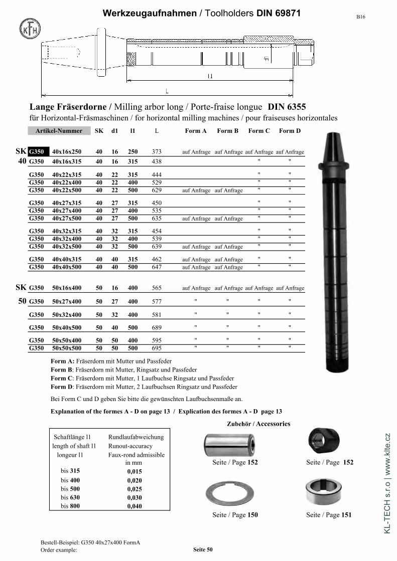
B16Werkzeugaufnahmen / Toolholders DIN 69871
Lange Fräserdorne /Milling arbor long / Porte-fraise longue DIN 6355für Horizontal-Fräsmaschinen / for horizontal milling machines / pour fraiseuses horizontalesArtikel-Nummer SK d1 l1 L Form A Form B Form C Form D
SK G350 40x16x250 40 16 250 373 auf Anfrage auf Anfrage auf Anfrage auf Anfrage
40 G350 40x16x315 40 16 315 438 " "
G350 40x22x315 40 22 315 444 " "G350 40x22x400 40 22 400 529 " "G350 40x22x500 40 22 500 629 auf Anfrage auf Anfrage " "
G350 40x27x315 40 27 315 450 " "G350 40x27x400 40 27 400 535 " "G350 40x27x500 40 27 500 635 auf Anfrage auf Anfrage " "
G350 40x32x315 40 32 315 454 " "G350 40x32x400 40 32 400 539 " "G350 40x32x500 40 32 500 639 auf Anfrage auf Anfrage " "
G350 40x40x315 40 40 315 462 auf Anfrage auf Anfrage " "G350 40x40x500 40 40 500 647 auf Anfrage auf Anfrage " "
SK G350 50x16x400 50 16 400 565 auf Anfrage auf Anfrage auf Anfrage auf Anfrage
50 G350 50x27x400 50 27 400 577 " " " "
G350 50x32x400 50 32 400 581 " " " "
G350 50x40x500 50 40 500 689 " " " "
G350 50x50x400 50 50 400 595 " " " "G350 50x50x500 50 50 500 695 " " " "
Form A: Fräserdorn mit Mutter und PassfederForm B: Fräserdorn mit Mutter, Ringsatz und PassfederForm C: Fräserdorn mit Mutter, 1 Laufbuchse Ringsatz und PassfederForm D: Fräserdorn mit Mutter, 2 Laufbuchsen Ringsatz und Passfeder
Bei Form C und D geben Sie bitte die gewünschten Laufbuchsenmaße an.
Explanation of the formes A - D on page 13 / Explication des formes A - D page 13
Zubehör / Accessories
Schaftlänge l1 Rundlaufabweichunglength of shaft l1 Runout-accuracylongeur l1 Faux-rond admissible
in mm Seite / Page 152 Seite / Page 152bis 315 0,015bis 400 0,020bis 500 0,025bis 630 0,030bis 800 0,040
Seite / Page 150 Seite / Page 151
Bestell-Beispiel: G350 40x27x400 FormAOrder example: Seite 50
KL-T
ECH
s.r.
o | w
ww
.klte
.cz

B16 Werkzeugaufnahmen / Toolholders DIN 69871
Prüfdorn DIN 69871Test Arbors DIN 69871Mandrins de contrôle DIN 69871
Nur zur Rundlauf-PrüfungOnly for test of run-outUniquement pour vérification de la concentricité
Artikel-Nummer
SK x d x A l1 Verwendung: zur Abnahme von Werkzeugmaschinen gemäß
ISO-Empfehlung R230, zur Rundlaufprüfung
G356 30 x 32 x 205 200 auf Anfrage und zum Ausrichten von Maschinenspindeln.
G356 40 x 30 x 300 289 Werkstoff: Legierter Einsatzstahl mit einer
G356 50 x 36 x 300 287 Mindestzugfestigkeit von 800N/mm².
Ausführung: Gehärtet: Vickershärte min. 630 HV10
(min. 56 HRC),
Kegel und Zapfen geschliffen.Besonderheit: Diese Prüfdorne sind unter Verwendung eines
Sonderbolzens auch geeignet für MAS-BT.Mit Ringnutbolzen als DIN 2080 einsetzbar.Maximale Rundlaufabweichung ist 0,003 mm
Usage: For testing of accuracy of machine spindle Application: Pour la réception technique des machinesMaterial: Alloyed case-hardened steel with a tensile Matiere: Acier de cémentation allié.
strength of 800N/mm². Resistance à la traction dans le noyauCarbonized accord. Vickers min. 630 HV10 mini. 800 N/mm²(min. 56 HRC), Version: Trempés Vickers mini. 630 HV10 (mini. 56 HRC),Shank and controll surface are grinded. cône et tenon rectifiés
Features: With special pull stud they can be used Spécificité: Avec tirettes speciale ces cônes peuvent également êtrefor DIN2080 as well as for MAS BT utilisés pour MAS-BT et pour DIN2080Max. runout is 0,003 mm Défaut de concentricité maxi. 0,003 mm
Bestell-Beisp.: G356 40x30x300Order example: Seite 51
KL-T
ECH
s.r.
o | w
ww
.klte
.cz

B16Werkzeugaufnahmen / Toolholders DIN 69871
Einsatzhülsen für MK mit Lappen DIN 6383Morse taper adaptor for flat tangDouilles intermédiares cône morse
avec tenon
Form AD Form AD/BRundlaufabweichung max 10µm zentrale Kühlmittelzufuhr kombinierbare KühlmittelzufuhrMax runout: 10µm coolant through center combined coolant versionFaux-rond admissible: 10µm max. arrosage central arrosage combine
SK x MK x A D L Artikel-Nr. Artikel-Nr.
SK 30 x 1 x 50 25 103 G360 30x1x 50 nur in AD30 30 x 1 x 100 25 148 G360 30x1x100 auf Anfrage nur in AD
30 x 2 x 65 32 113 G360 30x2x 65 nur in AD30 x 2 x 100 32 148 G360 30x2x100 auf Anfrage nur in AD
30 x 3 x 80 40 128 G360 30x3x 80 nur in AD
40 x 1 x 50 25 119 G360 40x1x 50 G360D 40x1x 50
SK 40 x 2 x 50 32 119 G360 40x2x 50 G360D 40x2x 5040 40 x 2 x 117 32 186 G360 40x2x117 nur in AD
40 x 2 x 150 32 219 G360 40x2x150 nur in AD40 x 2 x 200 32 269 G360 40x2x200 auf Anfrage nur in AD
40 x 3 x 70 40 139 G360 40x3x 70 G360D 40x3x 7040 x 3 x 133 40 202 G360 40x3x133 nur in AD40 x 3 x 200 40 269 G360 40x3x200 auf Anfrage nur in AD
40 x 4 x 95 48 164 G360 40x4x 95 G360D 40x4x 9540 x 4 x 156 48 226 G360 40x4x156 nur in AD40 x 4 x 200 48 269 G360 40x4x200 auf Anfrage nur in AD
Bestell-Beispiel: G360 40x2x50Order example: Seite 52
KL-T
ECH
s.r.
o | w
ww
.klte
.cz
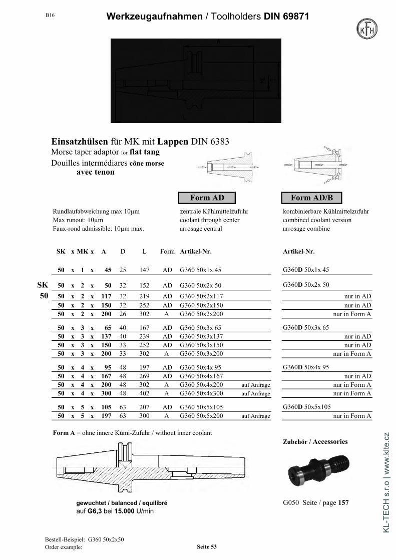
B16 Werkzeugaufnahmen / Toolholders DIN 69871
Einsatzhülsen für MK mit Lappen DIN 6383Morse taper adaptor for flat tangDouilles intermédiares cône morse
avec tenon
Form AD Form AD/BRundlaufabweichung max 10µm zentrale Kühlmittelzufuhr kombinierbare KühlmittelzufuhrMax runout: 10µm coolant through center combined coolant versionFaux-rond admissible: 10µm max. arrosage central arrosage combine
SK x MK x A D L Form Artikel-Nr. Artikel-Nr.
50 x 1 x 45 25 147 AD G360 50x1x 45 G360D 50x1x 45
SK 50 x 2 x 50 32 152 AD G360 50x2x 50 G360D 50x2x 50
50 50 x 2 x 117 32 219 AD G360 50x2x117 nur in AD50 x 2 x 150 32 252 AD G360 50x2x150 nur in AD50 x 2 x 200 26 302 A G360 50x2x200 nur in Form A
50 x 3 x 65 40 167 AD G360 50x3x 65 G360D 50x3x 6550 x 3 x 137 40 239 AD G360 50x3x137 nur in AD50 x 3 x 150 33 252 AD G360 50x3x150 nur in AD50 x 3 x 200 33 302 A G360 50x3x200 nur in Form A
50 x 4 x 95 48 197 AD G360 50x4x 95 G360D 50x4x 9550 x 4 x 167 48 269 AD G360 50x4x167 nur in AD50 x 4 x 200 48 302 A G360 50x4x200 auf Anfrage nur in Form A50 x 4 x 300 48 402 A G360 50x4x300 auf Anfrage nur in Form A
50 x 5 x 105 63 207 AD G360 50x5x105 G360D 50x5x10550 x 5 x 197 63 300 A G360 50x5x200 auf Anfrage nur in Form A
Form A = ohne innere Kümi-Zufuhr / without inner coolantZubehör / Accessories
gewuchtet / balanced / equilibré G050 Seite / page 157auf G6,3 bei 15.000 U/min
Bestell-Beispiel: G360 50x2x50Order example: Seite 53
KL-T
ECH
s.r.
o | w
ww
.klte
.cz
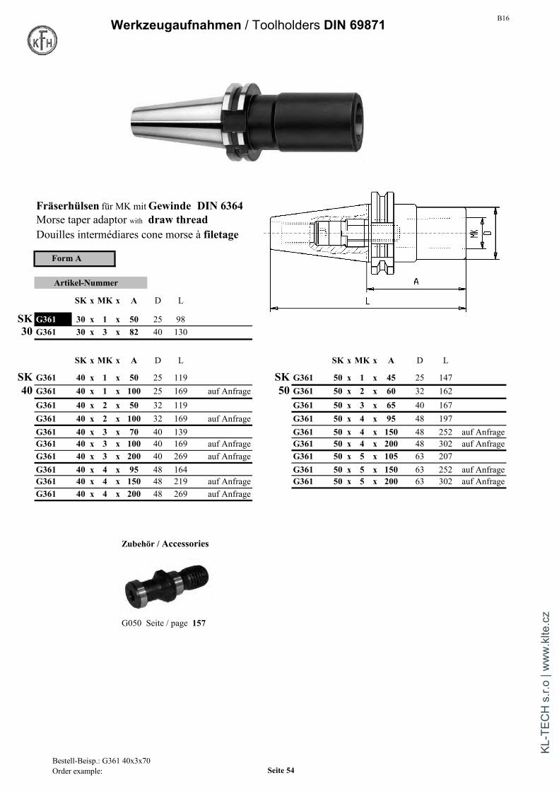
B16Werkzeugaufnahmen / Toolholders DIN 69871
Fräserhülsen für MK mitGewinde DIN 6364Morse taper adaptor with draw threadDouilles intermédiares cone morse à filetage
Form A
Artikel-Nummer
SK x MK x A D L
SK G361 30 x 1 x 50 25 9830 G361 30 x 3 x 82 40 130
SK x MK x A D L SK x MK x A D L
SK G361 40 x 1 x 50 25 119 SK G361 50 x 1 x 45 25 14740 G361 40 x 1 x 100 25 169 auf Anfrage 50 G361 50 x 2 x 60 32 162
G361 40 x 2 x 50 32 119 G361 50 x 3 x 65 40 167G361 40 x 2 x 100 32 169 auf Anfrage G361 50 x 4 x 95 48 197G361 40 x 3 x 70 40 139 G361 50 x 4 x 150 48 252 auf AnfrageG361 40 x 3 x 100 40 169 auf Anfrage G361 50 x 4 x 200 48 302 auf AnfrageG361 40 x 3 x 200 40 269 auf Anfrage G361 50 x 5 x 105 63 207G361 40 x 4 x 95 48 164 G361 50 x 5 x 150 63 252 auf AnfrageG361 40 x 4 x 150 48 219 auf Anfrage G361 50 x 5 x 200 63 302 auf AnfrageG361 40 x 4 x 200 48 269 auf Anfrage
Zubehör / Accessories
G050 Seite / page 157
Bestell-Beisp.: G361 40x3x70Order example: Seite 54
KL-T
ECH
s.r.
o | w
ww
.klte
.cz

B16 Werkzeugaufnahmen / Toolholders DIN 69871
Reduzierhülsen RohlingeReduction arbor Blank BarsDouilles de réduction Barreaux bruts
Artikel-Nummer Artikel-NummerSK x SK A D L SK x D x A L
Aussen InnenG362 40 x 30 50 50 119 G399 40 x 40 x 160 229G362 40 x 40 100 70 169 G399 40 x 63 x 160 229
G399 40 x 63 x 250 319G362 50 x 40 70 70 172G362 50 x 50 120 97 222 G399 50 x 97 x 315 417
Mit eingebauter Innensechskantschraube bei Bestellung bitte Kegel und Bund gehärtet auf Vickershärte min. 630 HVjedesmal angeben, ob ein Werkzeug nach DIN 2080, DIN 69871 (min. 56 HRC). Kegel und Bund geschliffen.oder MAS-BT aufgenommen werden soll. Zylinderschaft D mit 25-35HRC zum Weiterbearbeiten.
With internal clamping screw. Please give information wether Shank and collar carbonized accord. to Vickers min. 630 HVyou want to reduce on a taper DIN2080, DIN69871 or MAS BT. (min. 56 HRC) and grinded.
Cylindrical Diam. D with 25-35HRC for further manufact.Avec vis de serrage interieur. A la commande, merci de précisersi vous voulez réduire a DIN2080, DIN69871 ou MAS BT. Cône d'outils et collerette trempés et rectifiés,
queue D doux pour usinage ultérieur.
Bestell-Beisp.: G362 50x40Order example: Seite 55
KL-T
ECH
s.r.
o | w
ww
.klte
.cz

B16Werkzeugaufnahmen / Toolholders MAS - BT/JIS
Spannzangenfutter ER für Spannzangen DIN 6499Collet chuck ER / Syst. Regofix for collets DIN 6499Mandrin à pinces / Syst. Regofix pour pinces DIN 6499
Rundlaufabweichung:
SK zu Innenkegel 5 µm max.
Accuracy:
taper to inner cone 5µm max.
Precision: Form AD Form AD/BDéfaut de concentricité du cône zentrale Kühlmittelzufuhr kombinierbare Kühlmittelzufuhrau tenon maxi. 5µm coolant through center combined coolant version
arrosage central arrosage combiné
BT x ER x A L D Artikel-Nr. Artikel-Nr.
BT 30 x 16 x 70 118 32 G410 30x16x 70 nur in AD30 30 x 16 x 100 148 32 G410 30x16x100 nur in AD
30 x 25 x 70 118 42 G410 30x25x 70 nur in AD
30 x 32 x 70 118 50 G410 30x32x 70 nur in AD
BT 40 x 16 x 60 126 32 G410 40x16x 60 G410D 40x16x 6040 40 x 16 x 100 166 32 G410 40x16x100 G410D 40x16x100
40 x 16 x 160 226 32 G410 40x16x160 G410D 40x16x160
40 x 25 x 60 126 42 G410 40x25x 60 G410D 40x25x 6040 x 25 x 100 166 42 G410 40x25x100 G410D 40x25x10040 x 25 x 160 226 42 G410 40x25x160 G410D 40x25x160
40 x 32 x 60 126 50 G410 40x32x 60 G410D 40x32x 6040 x 32 x 100 166 50 G410 40x32x100 G410D 40x32x10040 x 32 x 160 226 50 G410 40x32x160 G410D 40x32x160
40 x 40 x 80 146 63 G410 40x40x 80 G410D 40x40x 8040 x 40 x 120 186 63 G410 40x40x120 nur in AD40 x 40 x 160 226 63 G410 40x40x160 G410D 40x40x160
40 x 50 x 122 188 78 nur in AD/B G410D 40x50x122 auf Anfrage
gewuchtet / balanced / equilibréauf G6,3 bei 15.000 U/min
Lieferumfang / Including:mit Spannmutter DIN6499with Collet-Nut DIN6499avec ecrou de serrage DIN6499
Bestell-Beisp.: G410 40x25x60Order example: G410 40x25x60 Seite 56
KL-T
ECH
s.r.
o | w
ww
.klte
.cz
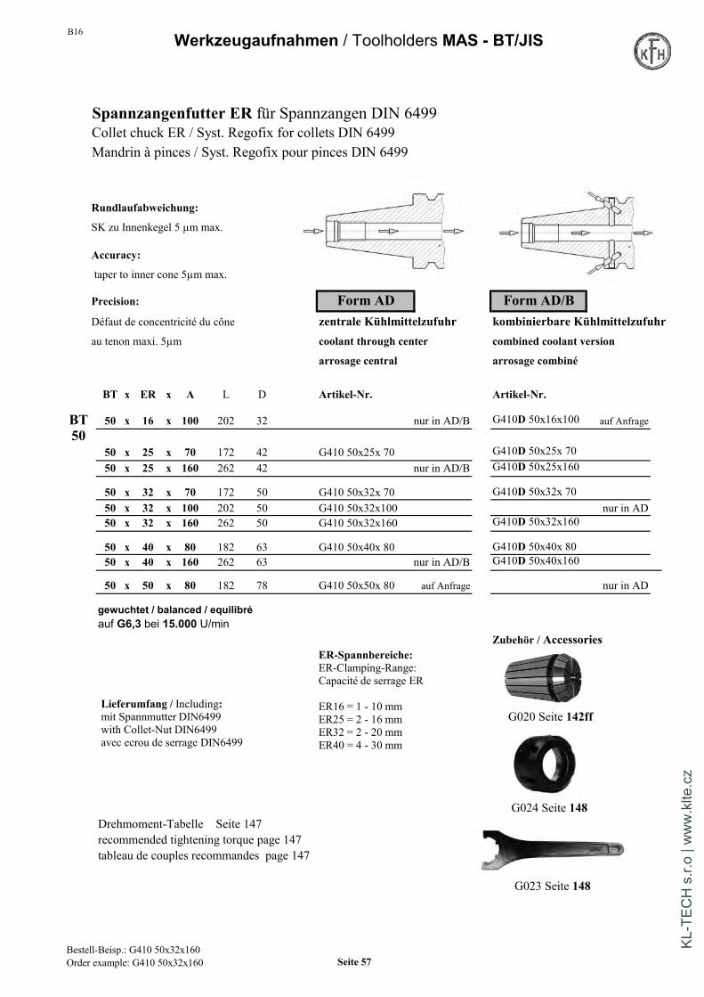
B16 Werkzeugaufnahmen / Toolholders MAS - BT/JIS
Spannzangenfutter ER für Spannzangen DIN 6499Collet chuck ER / Syst. Regofix for collets DIN 6499Mandrin à pinces / Syst. Regofix pour pinces DIN 6499
Rundlaufabweichung:
SK zu Innenkegel 5 µm max.
Accuracy:
taper to inner cone 5µm max.
Precision: Form AD Form AD/BDéfaut de concentricité du cône zentrale Kühlmittelzufuhr kombinierbare Kühlmittelzufuhrau tenon maxi. 5µm coolant through center combined coolant version
arrosage central arrosage combiné
BT x ER x A L D Artikel-Nr. Artikel-Nr.
BT 50 x 16 x 100 202 32 nur in AD/B G410D 50x16x100 auf Anfrage50
50 x 25 x 70 172 42 G410 50x25x 70 G410D 50x25x 7050 x 25 x 160 262 42 nur in AD/B G410D 50x25x160
50 x 32 x 70 172 50 G410 50x32x 70 G410D 50x32x 7050 x 32 x 100 202 50 G410 50x32x100 nur in AD50 x 32 x 160 262 50 G410 50x32x160 G410D 50x32x160
50 x 40 x 80 182 63 G410 50x40x 80 G410D 50x40x 8050 x 40 x 160 262 63 nur in AD/B G410D 50x40x160
50 x 50 x 80 182 78 G410 50x50x 80 auf Anfrage nur in AD
gewuchtet / balanced / equilibréauf G6,3 bei 15.000 U/min
Zubehör / Accessories
G020 Seite 142ff
G024 Seite 148Drehmoment-Tabelle Seite 147recommended tightening torque page 147tableau de couples recommandes page 147
G023 Seite 148
Lieferumfang / Including:mit Spannmutter DIN6499with Collet-Nut DIN6499avec ecrou de serrage DIN6499
ER-Spannbereiche:ER-Clamping-Range:Capacité de serrage ER
ER16 = 1 - 10 mmER25 = 2 - 16 mmER32 = 2 - 20 mmER40 = 4 - 30 mm
Bestell-Beisp.: G410 50x32x160Order example: G410 50x32x160 Seite 57
KL-T
ECH
s.r.
o | w
ww
.klte
.cz

B16Werkzeugaufnahmen / Toolholders MAS - BT/JIS
Form AD/BHydro-Dehnspannfutter kombinierbare Kühlmittelzufuhr
Hydraulic chuck combined coolant version
Mandrins hydrauliques expansibles arrosage combinée
Form AD/B gewuchtet / balanced / equilibréauf G2,5 bei 20.000 U/min
Artikel-Nummer Zubehör / Accessories / AccessoiresBT x d1 A l2 D D1
G414D 40 x 6 x 90 40 49,5 26 auf AnfrageG414D 40 x 8 x 90 40 49,5 28 auf AnfrageG414D 40 x 10 x 90 40 49,5 30 auf Anfrage Anzugsbolzen / Pull stud / TirettesG414D 40 x 12 x 90 40 49,5 32 G055 Seite/page 159G414D 40 x 16 x 90 46 49,5 38G414D 40 x 20 x 72,5 46 49,5 40 *G414D 40 x 20 x 90 46 49,5 40G414D 40 x 25 x 90 63 55 50G414D 40 x 32 x 90 63 63 56
G414D 50 x 10 x 110 41 49,5 30 auf AnfrageG414D 50 x 12 x 110 46 49,5 32 auf Anfrage Reduzierbüchsen fürG414D 50 x 16 x 110 49 49,5 38 auf Anfrage Hydrodehn-SpannfutterG414D 50 x 20 x 110 51 49,5 42 Collet for hydraulic chuckG414D 50 x 25 x 110 57 63 55 Douilles de réduction pourG414D 50 x 32 x 90 61 72 60 * mandrins hydrauliques expansiblesG414D 50 x 32 x 110 61 70 63 auf Anfrage G014a Seite/page 141
Mit Schlüssel / with wrench / avec clé de serrage
Drehzahl max. 40.000 U/min * Ausführung kurz und schwerDrehzahl ab 15.000 U/min erfordert Feinwuchten short and heavy versionMax. 40.000 rpm possible Version courte et lourdeRotations from 15.000 rpm on require fine-balancingMax. 40.000 rpm possibleRotations à partir de 15.000 rpm nécessitent un équilibrage fin
Rundlaufabweichung: 3 µm max.Accuracy: run-out 3µm max.Précision: défaut de concentricité maxi. 3µm
Handhabung: Auf keinen Fall ohne eingeführtes Werkzeug spannen.Usage: never clamp when there is no tooling inserted in the boreUtilisation: ne pas serrer sans outil dans alésage
Tabelle mit den übertragbaren Drehmomenten siehe Seite 94Tableau avec les couples transmissibles voir page 94
Bestell-Beisp.: G414D 50x20x90Order example Seite 58
KL-T
ECH
s.r.
o | w
ww
.klte
.cz

B16 Werkzeugaufnahmen / Toolholders MAS - BT/JIS
Kraftspannfutter High Power milling Chuck Mandrin à fort serrage
Form AD
Artikel-NummerBT x d L L1 D1 D
G418 40 x 20 x 90 23 49 46G418 40 x 20 x 150 23 49 46
G418 40 x 32 x 95 33 68 67G418 40 x 32 x 150 33 68 67
G418 50 x 20 x 100 23 49 46G418 50 x 20 x 150 23 49 46
G418 50 x 32 x 110 33 68 67G418 50 x 32 x 150 33 68 67
Reduzierbüchsen für Rundlaufabweichung: 4 µm max. bei 3 x d1 Kraft-SpannfutterRuhiger Lauf - geringe Vibrationen - hohe Steifigkeit Collet for high power milling chuckHohes Klemmdrehmoment durch maximalen Anlage-Kontakt Douilles de réduction pour Handhabung: Für Werkzeuge mit Schafttoleranz h6 mandrins à serrage fortSchneide des Werkzeugs nicht in die Aufnahmebohrung d1 einführen G014a Seite/page 141Gewuchtet G2,5 bei 20.000 U/min
Accuracy: run-out 4 µm max. at 3 x d1Smooth rotations, less vibrations, very rigidUsage: for toolings with shaft tolerance h6Do only insert shafts - not cutting edges in bore d1Balanced G2,5 at 20.000 rpm
Précision: défaut de concentricité maxi. 4 µm à 3 x d1Utilisation: ne pas serrer sans outil dans alésageEquilibré a G2,5 20.000 rpm
MIT Schlüssel / WITH wrench / AVEC clé
Bestell-Beisp.: G415 50x20Order example Seite 59
KL-T
ECH
s.r.
o | w
ww
.klte
.cz

B16Werkzeugaufnahmen / Toolholders MAS - BT/JIS
Spannzangenfutter OZ / DIN 6388Collet chuck OZ / Syst. Ortlieb gewuchtet / balanced / equilibréMandrin à pinces / Syst. Ortlieb auf G6,3 bei 15.000 U/min
Form AD zentrale Kühlmittelzufuhrcoolant through center
Artikel-Nummer arrosage central
BT x OZ x A L D
G416 30 x 16 x 60 108 43G416 30 x 25 x 80 128 60
G416 40 x 16 x 70 136 43 Zubehör / AccessoriesG416 40 x 25 x 70 136 60 *G416 40 x 32 x 90 156 72 *
G416 50 x 25 x 85 187 60 *G416 50 x 32 x 90 192 72 * G016 Seite 140
* in Version AD/B auf Anfrage* version AD/B on request* version AD/B sur demande
G018 Seite 141
G017 Seite 141
Rundlaufabweichung: SK zu Innenkegel 5 µm max.Accuracy: taper to inner cone 5µm max.Précision: défaut de concentricité du cône au tenon maxi. 5µm
G055 Seite 159
Lieferumfang / Including:mit Spannmutter DIN6388Dwith Collet-Nut DIN6388Davec ecrou de serrage DIN6388D
OZ-Spannbereiche:OZ-Clamping-Range:Capacité de serrage OZ:
OZ16 / 415E = 2 - 16 mmOZ25 / 462E = 2 - 25 mmOZ32 / 467E = 3 - 32 mm
Bestell-Beisp.: G416 50x25x85Order example: Seite 60
KL-T
ECH
s.r.
o | w
ww
.klte
.cz

B16 Werkzeugaufnahmen / Toolholders MAS - BT/JIS
Gewindeschneid-Schnellwechselfuttermit Längenausgleich auf Druck und Zug
Quick change tapping chuck with compensationMandrins de taraudage avec compensation de longueur sur pression/traction
Form A
Artikel-Nummer Zubehör / AccessoriesBT x Gr A d D Gewinde
mit KupplungG417 30 x 1 63 19 38 M3-M12 with clutchG417 30 x 2 96 31 55 M8-M20 avec coupleur
G013 mit Seite 139G417 40 x 1 68 19 38 M3-M12G417 40 x 2 93 31 55 M8-M20G417 40 x 3 138 48 79 M14-M33 ohne Kupplung
without clutchG417 50 x 1 80 19 38 M3-M12 sans coupleurG417 50 x 2 102 31 55 M8-M20 G013 ohne Seite 139G417 50 x 3 133 48 79 M14-M33G417 50 x 4 147 60 98 M22-M48
Verwendung: Zur Aufnahme von Schnellwechseleinsätzen für Gewindebohrer.Längenausgleich auf Zug und DruckAusführung mit Kugelführungsbuchse
Usage: For mounting quick change tapping colletsWith length compensation on tension and compressionVersion with ball retainer
Utilisation: Pour le serrage d'adaptateurs de taraudageAvec compensation de longueur sur pression/tractionVersion avec guidage à bille
Ausgleichsweg auf Zug und DruckCompensation sur pression/traction Tabelle mit Gewindebohrer-Schaftmaßen siehe S.138Größe 1: je 9 mm Dimensions of tap-shafts see page 138Größe 2: je 15 mm Tableau avec dimensions de queues de tarauds page 7Größe 3: je 24 mm
Bestell-Beisp.: G417 40x2Order example Seite 61
KL-T
ECH
s.r.
o | w
ww
.klte
.cz

B16Werkzeugaufnahmen / Toolholders MAS - BT/JIS
Spannfutter Weldon Form AD Form AD/BEndmill-holder Weldon /DIN1835Bzentrale Kühlmittelzufuhr kombinierbare KühlmittelzufuhrPorte-fraises Weldon /DIN1835B coolant through center combined coolant version
arrosage central arrosage combiné
BT x d1 x A L D Artikel-Nr. Artikel-Nr.
BT 30 x 6 x 50 98 25 G420 30x 6x 50 nur in AD30 30 x 8 x 50 98 28 G420 30x 8x 50 nur in AD
30 x 10 x 50 98 35 G420 30x10x 50 nur in AD30 x 12 x 50 98 42 G420 30x12x 50 nur in AD30 x 14 x 50 98 42 G420 30x14x 50 nur in AD30 x 16 x 63 111 48 G420 30x16x 63 nur in AD30 x 20 x 63 111 52 G420 30x20x 63 nur in AD
BT 40 x 6 x 50 116 25 G420 40x 6x 50 G420D 40x 6x 5040 40 x 6 x 100 166 25 G420 40x 6x100 G420D 40x 6x1006mm 40 x 6 x 160 226 25 G420 40x 6x160 G420D 40x 6x160
40 x 8 x 50 116 28 G420 40x 8x 50 G420D 40x 8x 508mm 40 x 8 x 100 166 28 G420 40x 8x100 G420D 40x 8x100
40 x 8 x 160 226 28 G420 40x 8x160 G420D 40x 8x160
40 x 10 x 63 129 35 G420 40x10x 63 G420D 40x10x 6340 x 10 x 100 166 35 G420 40x10x100 G420D 40x10x100
10mm 40 x 10 x 160 226 35 G420 40x10x160 G420D 40x10x160
40 x 12 x 63 129 42 G420 40x12x 63 G420D 40x12x 6312mm 40 x 12 x 100 166 42 G420 40x12x100 G420D 40x12x100
40 x 12 x 160 226 42 G420 40x12x160 G420D 40x12x160
14mm 40 x 14 x 63 129 42 G420 40x14x 63 G420D 40x14x 6340 x 14 x 100 166 42 G420 40x14x100 G420D 40x14x100
40 x 16 x 63 129 48 G420 40x16x 63 G420D 40x16x 6316mm 40 x 16 x 100 166 48 G420 40x16x100 G420D 40x16x100
40 x 16 x 160 226 48 G420 40x16x160 G420D 40x16x160
gewuchtet /balanced / equilibré auf G6,3 bei 15.000 U/min
Die KFH Weldon-Spannfutterwerden mit
EXZENTRISCHER Bohrunggefertigt !
Rundlaufabweichung siehe Seite 31
Bestell-Beisp.: G420 40x10x63 (Form AD)G420D 40x10x63 (Form AD/B) Seite 62
KL-T
ECH
s.r.
o | w
ww
.klte
.cz

B16 Werkzeugaufnahmen / Toolholders MAS - BT/JIS
Spannfutter Weldon Form AD Form AD/BEndmill-holder Weldon /DIN1835B zentrale Kühlmittelzufuhr kombinierbare Kühlmittelzufuhr
Porte-fraise Weldon /DIN1835B coolant through center combined coolant versionarrosage central arrosage combiné
Drehmoment-Tabelle Seite 147recommended tightening torque page 147tableau de couples recommandes page 147
BT BT x d1 x A L D Artikel-Nr. Artikel-Nr.40
18mm 40 x 18 x 63 129 48 G420 40x18x 63 G420D 40x18x 6340 x 18 x 100 166 48 G420 40x18x100 G420D 40x18x100
40 x 20 x 63 129 52 G420 40x20x 63 G420D 40x20x 6320mm 40 x 20 x 100 166 52 G420 40x20x100 G420D 40x20x100
40 x 20 x 160 226 52 G420 40x20x160 G420D 40x20x160
40 x 25 x 35 101 65 G420 40x25x 35 nur in AD25mm 40 x 25 x 100 166 63 G420 40x25x100 G420D 40x25x100
40 x 25 x 160 226 65 nur in AD/B G420D 40x25x160
40 x 32 x 100 166 70 G420 40x32x100 G420D 40x32x10032mm 40 x 32 x 160 226 72 nur in AD/B G420D 40x32x160
40mm 40 x 40 x 120 176 80 G420 40x40x120 G420D 40x40x120
BT50 50 x 6 x 63 165 25 G420 50x 6x 63 G420D 50x 6x 636mm 50 x 6 x 160 262 25 G420 50x 6x160 G420D 50x 6x160 auf Anfrage
50 x 8 x 63 165 28 G420 50x 8x 63 G420D 50x 8x 638mm 50 x 8 x 160 262 28 G420 50x 8x160 G420D 50x 8x160 auf Anfrage
50 x 10 x 63 165 35 G420 50x10x 63 G420D 50x10x 6310mm 50 x 10 x 160 262 35 G420 50x10x160 G420D 50x10x160 auf Anfrage
50 x 12 x 80 182 42 G420 50x12x 80 G420D 50x12x 8012mm 50 x 12 x 160 262 42 G420 50x12x160 G420D 50x12x160 auf Anfrage
14mm 50 x 14 x 80 182 42 G420 50x14x 80 G420D 50x14x 80
50 x 16 x 80 182 48 G420 50x16x 80 G420D 50x16x 8016mm 50 x 16 x 160 262 48 G420 50x16x160 G420D 50x16x160 auf Anfrage
18mm 50 x 18 x 80 182 48 G420 50x18x 80 G420D 50x18x 80
50 x 20 x 80 182 52 G420 50x20x 80 G420D 50x20x 8050 x 20 x 100 202 52 G420 50x20x100 nur in AD
20mm 50 x 20 x 160 262 52 G420 50x20x160 G420D 50x20x160 auf Anfrage
50 x 25 x 100 202 63 G420 50x25x100 G420D 50x25x10025mm 50 x 25 x 160 262 65 G420 50x25x160 G420D 50x25x160 auf Anfrage
50 x 32 x 105 207 70 G420 50x32x105 G420D 50x32x10532mm 50 x 32 x 160 262 72 G420 50x32x160 G420D 50x32x160 auf Anfrage
40mm 50 x 40 x 120 222 80 G420 50x40x120 G420D 50x40x120
gewuchtet /balanced / equilibré auf G6,3 bei 15.000 U/min
Bestell-Beisp.: G420 50x20x80 (Form AD)G420D 50x20x80 (Form AD/B) Seite 63
KL-T
ECH
s.r.
o | w
ww
.klte
.cz
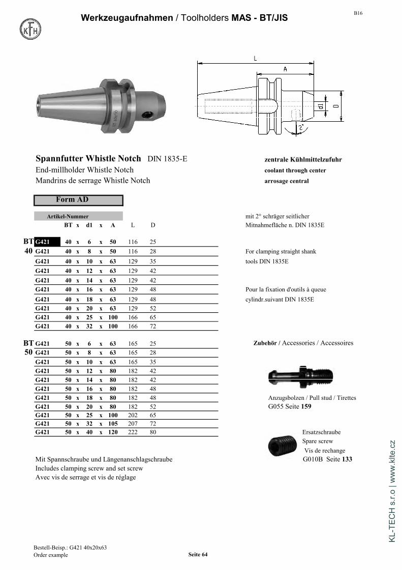
B16Werkzeugaufnahmen / Toolholders MAS - BT/JIS
Spannfutter Whistle Notch DIN 1835-E zentrale KühlmittelzufuhrEnd-millholder Whistle Notch coolant through center
Mandrins de serrage Whistle Notch arrosage central
Form AD
Artikel-Nummer mit 2° schräger seitlicherBT x d1 x A L D Mitnahmefläche n. DIN 1835E
BTG421 40 x 6 x 50 116 2540 G421 40 x 8 x 50 116 28 For clamping straight shank
G421 40 x 10 x 63 129 35 tools DIN 1835EG421 40 x 12 x 63 129 42G421 40 x 14 x 63 129 42G421 40 x 16 x 63 129 48 Pour la fixation d'outils à queueG421 40 x 18 x 63 129 48 cylindr.suivant DIN 1835EG421 40 x 20 x 63 129 52G421 40 x 25 x 100 166 65G421 40 x 32 x 100 166 72
BTG421 50 x 6 x 63 165 25 Zubehör / Accessories / Accessoires50 G421 50 x 8 x 63 165 28
G421 50 x 10 x 63 165 35G421 50 x 12 x 80 182 42G421 50 x 14 x 80 182 42G421 50 x 16 x 80 182 48G421 50 x 18 x 80 182 48 Anzugsbolzen / Pull stud / TirettesG421 50 x 20 x 80 182 52 G055 Seite 159G421 50 x 25 x 100 202 65G421 50 x 32 x 105 207 72G421 50 x 40 x 120 222 80 Ersatzschraube
Spare screwVis de rechange
Mit Spannschraube und Längenanschlagschraube G010B Seite 133Includes clamping screw and set screwAvec vis de serrage et vis de réglage
Bestell-Beisp.: G421 40x20x63Order example Seite 64
KL-T
ECH
s.r.
o | w
ww
.klte
.cz
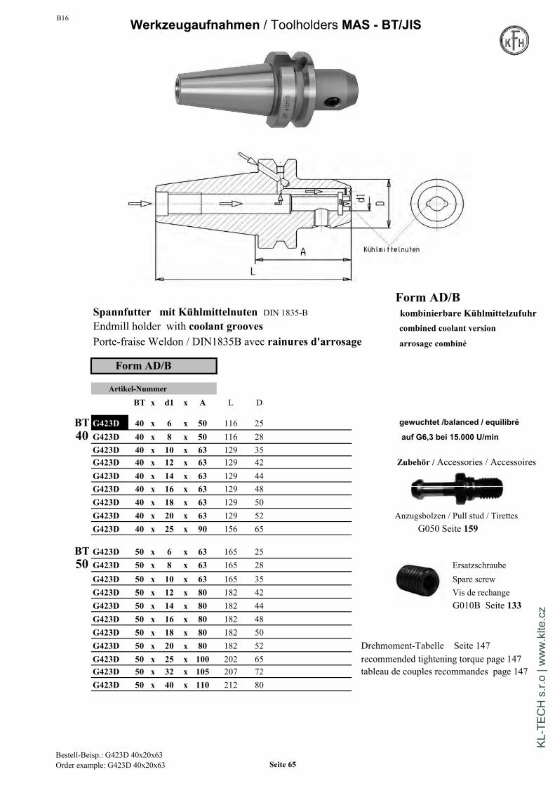
B16 Werkzeugaufnahmen / Toolholders MAS - BT/JIS
Form AD/BSpannfutter mit Kühlmittelnuten DIN 1835-B kombinierbare KühlmittelzufuhrEndmill holder with coolant grooves combined coolant versionPorte-fraise Weldon / DIN1835B avec rainures d'arrosage arrosage combiné
Form AD/B
Artikel-Nummer
BT x d1 x A L D
BT G423D 40 x 6 x 50 116 25 gewuchtet /balanced / equilibré
40 G423D 40 x 8 x 50 116 28 auf G6,3 bei 15.000 U/minG423D 40 x 10 x 63 129 35G423D 40 x 12 x 63 129 42 Zubehör / Accessories / AccessoiresG423D 40 x 14 x 63 129 44G423D 40 x 16 x 63 129 48G423D 40 x 18 x 63 129 50G423D 40 x 20 x 63 129 52 Anzugsbolzen / Pull stud / TirettesG423D 40 x 25 x 90 156 65 G050 Seite 159
BT G423D 50 x 6 x 63 165 2550 G423D 50 x 8 x 63 165 28 Ersatzschraube
G423D 50 x 10 x 63 165 35 Spare screwG423D 50 x 12 x 80 182 42 Vis de rechangeG423D 50 x 14 x 80 182 44 G010B Seite 133G423D 50 x 16 x 80 182 48G423D 50 x 18 x 80 182 50G423D 50 x 20 x 80 182 52 Drehmoment-Tabelle Seite 147G423D 50 x 25 x 100 202 65 recommended tightening torque page 147G423D 50 x 32 x 105 207 72 tableau de couples recommandes page 147G423D 50 x 40 x 110 212 80
Bestell-Beisp.: G423D 40x20x63Order example: G423D 40x20x63 Seite 65
KL-T
ECH
s.r.
o | w
ww
.klte
.cz
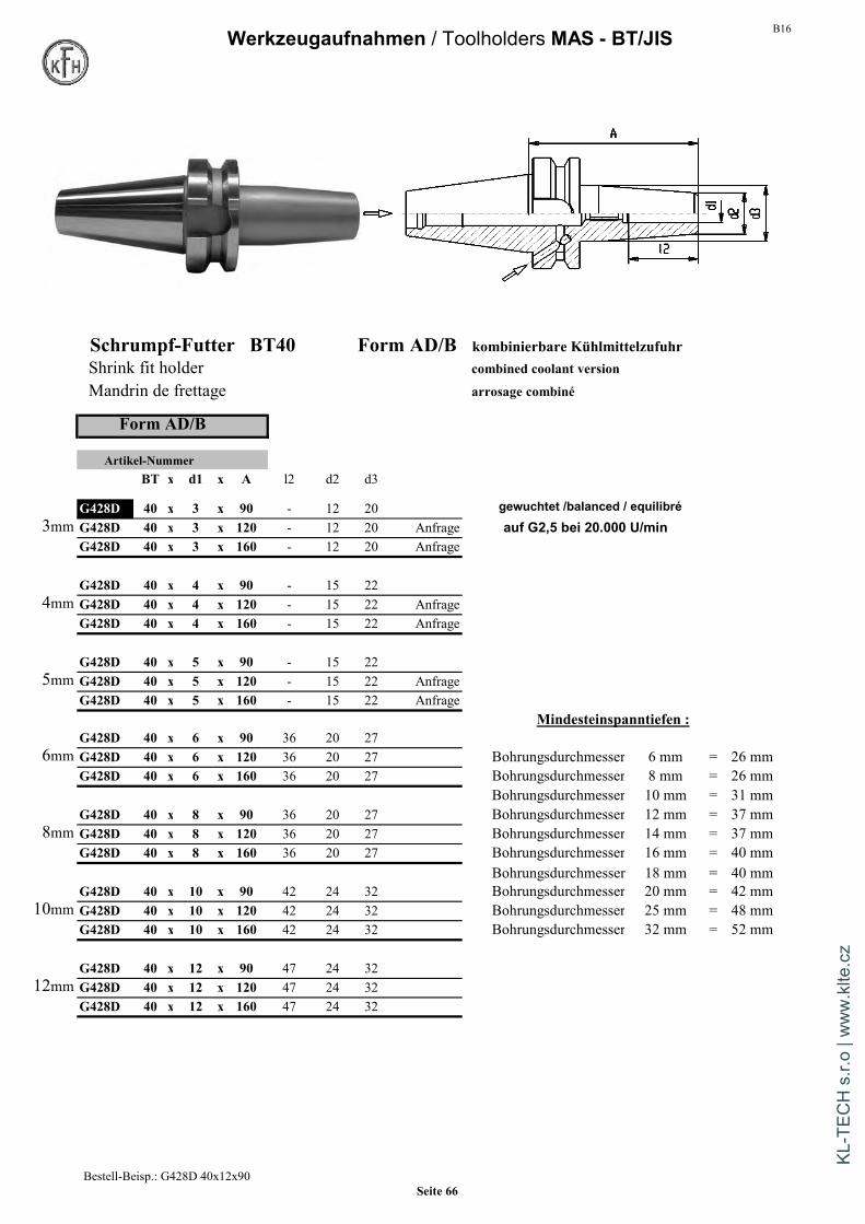
B16Werkzeugaufnahmen / Toolholders MAS - BT/JIS
Schrumpf-Futter BT40 Form AD/B kombinierbare KühlmittelzufuhrShrink fit holder combined coolant version
Mandrin de frettage arrosage combiné
Form AD/B
Artikel-NummerBT x d1 x A l2 d2 d3
G428D 40 x 3 x 90 - 12 20 gewuchtet /balanced / equilibré3mm G428D 40 x 3 x 120 - 12 20 Anfrage auf G2,5 bei 20.000 U/min
G428D 40 x 3 x 160 - 12 20 Anfrage
G428D 40 x 4 x 90 - 15 224mm G428D 40 x 4 x 120 - 15 22 Anfrage
G428D 40 x 4 x 160 - 15 22 Anfrage
G428D 40 x 5 x 90 - 15 225mm G428D 40 x 5 x 120 - 15 22 Anfrage
G428D 40 x 5 x 160 - 15 22 AnfrageMindesteinspanntiefen :
G428D 40 x 6 x 90 36 20 276mm G428D 40 x 6 x 120 36 20 27 Bohrungsdurchmesser 6 mm = 26 mm
G428D 40 x 6 x 160 36 20 27 Bohrungsdurchmesser 8 mm = 26 mmBohrungsdurchmesser 10 mm = 31 mm
G428D 40 x 8 x 90 36 20 27 Bohrungsdurchmesser 12 mm = 37 mm8mm G428D 40 x 8 x 120 36 20 27 Bohrungsdurchmesser 14 mm = 37 mm
G428D 40 x 8 x 160 36 20 27 Bohrungsdurchmesser 16 mm = 40 mmBohrungsdurchmesser 18 mm = 40 mm
G428D 40 x 10 x 90 42 24 32 Bohrungsdurchmesser 20 mm = 42 mm10mm G428D 40 x 10 x 120 42 24 32 Bohrungsdurchmesser 25 mm = 48 mm
G428D 40 x 10 x 160 42 24 32 Bohrungsdurchmesser 32 mm = 52 mm
G428D 40 x 12 x 90 47 24 3212mm G428D 40 x 12 x 120 47 24 32
G428D 40 x 12 x 160 47 24 32
Bestell-Beisp.: G428D 40x12x90Seite 66
KL-T
ECH
s.r.
o | w
ww
.klte
.cz

B16 Werkzeugaufnahmen / Toolholders MAS - BT/JIS
Schrumpf-Futter BT40 Form AD/B kombinierbare KühlmittelzufuhrShrink fit holder combined coolant version
Mandrin de frettage arrosage combiné
Form AD/B
Artikel-NummerBT x d1 x A l2 d2 d3
G428D 40 x 14 x 90 48 27 34 gewuchtet /balanced / equilibré
14mm G428D 40 x 14 x 120 48 27 34 auf G2,5 bei 20.000 U/minG428D 40 x 14 x 160 48 27 34
G428D 40 x 16 x 90 51 27 3416mm G428D 40 x 16 x 120 51 27 34
G428D 40 x 16 x 160 51 27 34
G428D 40 x 18 x 90 51 33 42 Zubehör / Accessories / Accessoires18mm G428D 40 x 18 x 120 51 33 42
G428D 40 x 18 x 160 51 33 42
G428D 40 x 20 x 90 53 33 4220mm G428D 40 x 20 x 120 53 33 42
G428D 40 x 20 x 160 53 33 42
25mm G428D 40 x 25 x 100 58 44 53 Anzugsbolzen / Pull stud / TirettesG428D 40 x 25 x 160 58 44 53 G055 Seite 159
32mm G428D 40 x 32 x 100 58 44 53G428D 40 x 32 x 160 58 44 53 Anfrage
Schrumpf-VerlängerungenShrink extension allongeRallonges de frettageG028 Seite 149
Bestell-Beisp.: G328D 40x20x90Seite 67
KL-T
ECH
s.r.
o | w
ww
.klte
.cz
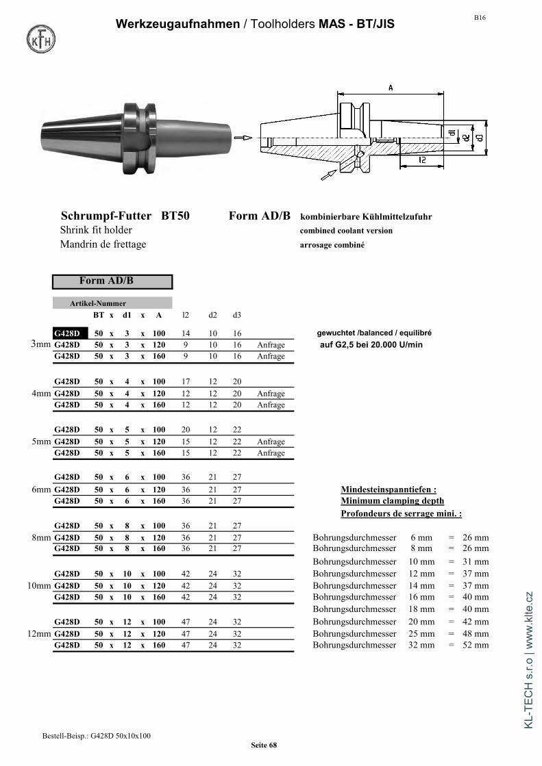
B16Werkzeugaufnahmen / Toolholders MAS - BT/JIS
Schrumpf-Futter BT50 Form AD/B kombinierbare KühlmittelzufuhrShrink fit holder combined coolant version
Mandrin de frettage arrosage combiné
Form AD/B
Artikel-NummerBT x d1 x A l2 d2 d3
G428D 50 x 3 x 100 14 10 16 gewuchtet /balanced / equilibré3mm G428D 50 x 3 x 120 9 10 16 Anfrage auf G2,5 bei 20.000 U/min
G428D 50 x 3 x 160 9 10 16 Anfrage
G428D 50 x 4 x 100 17 12 204mm G428D 50 x 4 x 120 12 12 20 Anfrage
G428D 50 x 4 x 160 12 12 20 Anfrage
G428D 50 x 5 x 100 20 12 225mm G428D 50 x 5 x 120 15 12 22 Anfrage
G428D 50 x 5 x 160 15 12 22 Anfrage
G428D 50 x 6 x 100 36 21 276mm G428D 50 x 6 x 120 36 21 27 Mindesteinspanntiefen :
G428D 50 x 6 x 160 36 21 27 Minimum clamping depthProfondeurs de serrage mini. :
G428D 50 x 8 x 100 36 21 278mm G428D 50 x 8 x 120 36 21 27 Bohrungsdurchmesser 6 mm = 26 mm
G428D 50 x 8 x 160 36 21 27 Bohrungsdurchmesser 8 mm = 26 mmBohrungsdurchmesser 10 mm = 31 mm
G428D 50 x 10 x 100 42 24 32 Bohrungsdurchmesser 12 mm = 37 mm10mm G428D 50 x 10 x 120 42 24 32 Bohrungsdurchmesser 14 mm = 37 mm
G428D 50 x 10 x 160 42 24 32 Bohrungsdurchmesser 16 mm = 40 mmBohrungsdurchmesser 18 mm = 40 mm
G428D 50 x 12 x 100 47 24 32 Bohrungsdurchmesser 20 mm = 42 mm12mm G428D 50 x 12 x 120 47 24 32 Bohrungsdurchmesser 25 mm = 48 mm
G428D 50 x 12 x 160 47 24 32 Bohrungsdurchmesser 32 mm = 52 mm
Bestell-Beisp.: G428D 50x10x100Seite 68
KL-T
ECH
s.r.
o | w
ww
.klte
.cz

B16 Werkzeugaufnahmen / Toolholders MAS - BT/JIS
Schrumpf-Futter BT50 Form AD/B kombinierbare KühlmittelzufuhrShrink fit holder combined coolant version
Mandrin de frettage arrosage combiné
Form AD/B
Artikel-NummerBT x d1 x A l2 d2 d3
G428D 50 x 14 x 100 47 27 34 gewuchtet /balanced / equilibré
14mm G428D 50 x 14 x 120 47 27 34 auf G2,5 bei 20.000 U/minG428D 50 x 14 x 160 47 27 34
G428D 50 x 16 x 100 50 27 3416mm G428D 50 x 16 x 120 50 27 34
G428D 50 x 16 x 160 50 27 34
G428D 50 x 18 x 100 50 33 42 Zubehör / Accessories / Accessoires18mm G428D 50 x 18 x 120 50 33 42
G428D 50 x 18 x 160 50 33 42
G428D 50 x 20 x 100 52 33 4220mm G428D 50 x 20 x 120 52 33 42 Anzugsbolzen / Pull stud
G428D 50 x 20 x 160 52 33 42 G055 Seite 159
25mm G428D 50 x 25 x 110 58 44 53G428D 50 x 25 x 160 58 44 53
32mm G428D 50 x 32 x 110 62 44 53 Schrumpf-VerlängerungenG428D 50 x 32 x 160 62 44 53 Shrink extension allonge
Rallonges de frettageG028 Seite 149
Bestell-Beisp.: G428D 50x20x100Seite 69
KL-T
ECH
s.r.
o | w
ww
.klte
.cz
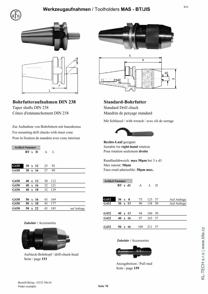
B16Werkzeugaufnahmen / Toolholders MAS - BT/JIS
Bohrfutteraufnahmen DIN 238 Standard-BohrfutterTaper shafts DIN 238 Standard Drill chuckCônes d'emmanchement DIN 238 Mandrin de perçage standard
Mit Schlüssel / with wrench / avec clé de serrageZur Aufnahme von Bohrfuttern mit InnenkonusFor mounting drill chucks with inner conePour la fixation de mandrin avec cone interieur
Rechts-Lauf geeignetArtikel-Nummer Suitable for right-hand rotation
BT x D A L Pour rotation seulement droite
Rundlaufabweich.max 50µm bei 3 x d1G430 30 x 12 25 92 Max runout: 50µmG430 30 x 16 27 99 Faux-rond admissible: 50µm max.
G430 40 x 12 30 112 Artikel-NummerG430 40 x 16 32 121 BT x d1 A L DG430 40 x 18 32 129
G430 50 x 16 43 169 G432 30 x 8 75 123 37 Auf AnfrageG430 50 x 18 43 177 G432 30 x 13 90 138 50 Auf AnfrageG430 50 x 22 43 185 auf Anfrage
G432 40 x 13 94 160 50G432 40 x 16 97 163 57
Zubehör / AccessoriesG432 50 x 16 109 211 57
Zubehör / Accessories
Aufsteck-Bohrkopf / drill-chuck-headSeite / page 153
Anzugsbolzen / Pull studSeite / page 159
Bestell-Beisp.: G332 50x16Order example: Seite 70
KL-T
ECH
s.r.
o | w
ww
.klte
.cz

B16 Werkzeugaufnahmen / Toolholders MAS - BT/JIS
Präzisions-Bohrfutter Hoch-Präzisions-BohrfutterPrecision Drill chuck High-precision Drill chuckMandrin de percage precision Mandrin de percage haute-precision
Mit Schlüssel / with wrench / avec clé de serrage Mit Schlüssel / with wrench / avec clé de serrage
Rechts-Linkslauf geeignet Rechts-Linkslauf geeignetSuitable for right-hand and left-hand rotation Suitable for right-hand and left-hand rotationPour rotation gauche-droite Pour rotation gauche-droite
Rundlaufabweich.max 35µm bei 3 x d1 Rundlaufabweich.max 20µm bei 3 x d1Max runout: 35µm Max runout: 20µmFaux-rond admissible: 35µm max. Faux-rond admissible: 20µm max.
Artikel-Nummer Form AD/B Artikel-NummerBT x d1 A D Bereich BT x d1 A D Bereich
G433D 40 x 13 98 50 1-13 G434 30 x 8 74 36 0,3-8G433D 40 x 16 103 50 2,5-16 G434 30 x 13 96 50 0,5-13
G433D 50 x 16 115 50 2,5-16 G434 40 x 8 81 36 0,3-8G434 40 x 13 98 50 0,5-13G434 40 x 16 103 57 2,5-16
Präzisionsbohrfutter / Precision drill chuckWeitere techn. Informationen / Anzugsmomente S. 75 G434 50 x 13 110 50 0,5-13Further technical information / tightening torque page 75 G434 50 x 16 115 57 2,5-16
Artikel-Nummer Form AD/BSK x d1 A D
G434D 40 x 8 81 36 0,3-8Hoch-Präzisionsbohrfutter / High-Precision drill chuck G434D 40 x 13 98 50 0,5-13Weitere techn. Informationen / Anzugsmomente S.137 G434D 40 x 16 103 57 2,5-16Further technical information / tightening torque page 137
G434D 50 x 13 110 50 0,5-13G434D 50 x 16 115 57 2,5-16
Bestell-Beisp.: G333 40x13Order example: Seite 71
KL-T
ECH
s.r.
o | w
ww
.klte
.cz

B16Werkzeugaufnahmen / Toolholders MAS - BT/JIS
Kombi-Aufsteckfräserdorn DIN 6358Combi shell mill holderPorte-fraise à double usage
Form A
Artikel-Nummer
BT x d1 x A L l5 l1 d2
BT G440 30 x 13 x 45 105 12 22 28 auf Anfrage30
G440 30 x 16 x 45 110 17 27 32
G440 30 x 22 x 47 114 19 31 40
G440 30 x 27 x 49 118 21 33 48
Ersatzteile / Spare parts
G040 Seite/ Page 154 G041 Seite/ Page 154
G042 Seite/ Page 154
Ausführung MAS-BT in BT 35 auf AnfrageVersion MAS-BT in BT 35 on requestVersion MAS-BT en BT 35 sur demande
Zur Aufnahme von Fräsern mitLängs- oder QuernutLieferumfang: mit Fräseranzugs-schraube, Mitnehmerringund PaßfederRundlaufabweichung des Kegelszur Fräseraufnahme 8 µm max
For mounting of milling cutterswith tenon drive or clutch driveScope of delivery:with clamping screw DIN6367,drive ring DIN 6366 and feather keyRunout of taper to journal8 µm max
Pour la fixation d'outils a rainureslongitudinales ou transversalesAvec bague de tenons, clavette et visde serrageFaux-rond admissible du cone autourillon 8 µm max
Bestell-Beispiel: G440 30x27x49Order example Seite 72
KL-T
ECH
s.r.
o | w
ww
.klte
.cz
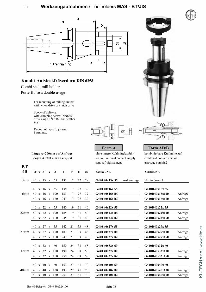
B16 Werkzeugaufnahmen / Toolholders MAS - BT/JIS
Kombi-Aufsteckfräserdorn DIN 6358Combi shell mill holderPorte-fraise à double usage
Form A Form AD/BLänge A=200mm auf Anfrage ohne innere Kühlmittelzufuhr kombinierbare Kühlmittelzuf.Length A=200 mm on request without internal coolant supply combined coolant version
sans refroidissement arrosage combinéBT40 BT x d1 x A L l5 l1 d2 Artikel-Nr. Artikel-Nr.
13mm 40 x 13 x 55 133 12 22 28 G440 40x13x 55 Auf Anfrage Nur in Form A
40 x 16 x 55 138 17 27 32 G440 40x16x 55 G440D40x16x 5516mm 40 x 16 x 100 183 17 27 32 G440 40x16x100 G440D40x16x100 Anfrage
40 x 16 x 160 243 17 27 32 G440 40x16x160 G440D40x16x160 Anfrage
40 x 22 x 55 140 19 31 40 G440 40x22x 55 G440D40x22x 55
22mm 40 x 22 x 100 185 19 31 40 G440 40x22x100 G440D40x22x100 Anfrage40 x 22 x 160 245 19 31 40 G440 40x22x160 G440D40x22x160 Anfrage
40 x 27 x 55 142 21 33 48 G440 40x27x 55 G440D40x27x 55
27mm 40 x 27 x 100 187 21 33 48 G440 40x27x100 G440D40x27x100 Anfrage40 x 27 x 160 247 21 33 48 G440 40x27x160 G440D40x27x160 Anfrage
40 x 32 x 60 150 24 38 58 G440 40x32x 60 G440D40x32x 60
32mm 40 x 32 x 100 190 24 38 58 G440 40x32x100 G440D40x32x100 Anfrage40 x 32 x 160 250 24 38 58 G440 40x32x160 G440D40x32x160 Anfrage
40 x 40 x 60 153 27 41 70 G440 40x40x 60 G440D40x40x 60
40mm 40 x 40 x 100 193 27 41 70 G440 40x40x100 G440D40x40x100 Anfrage40 x 40 x 160 253 27 41 70 G440 40x40x160 G440D40x40x160 Anfrage
For mounting of milling cutterswith tenon drive or clutch drive
Scope of delivery:with clamping screw DIN6367,drive ring DIN 6366 and featherkey
Runout of taper to journal8 µm max
Bestell-Beispiel: G440 40x32x100 Seite 73
KL-T
ECH
s.r.
o | w
ww
.klte
.cz
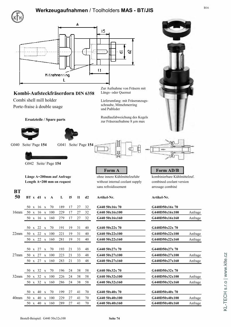
B16Werkzeugaufnahmen / Toolholders MAS - BT/JIS
Kombi-Aufsteckfräserdorn DIN 6358Combi shell mill holderPorte-fraise à double usage
Ersatzteile / Spare parts
G040 Seite/ Page 154 G041 Seite/ Page 154
G042 Seite/ Page 154
Form A Form AD/BLänge A=200mm auf Anfrage ohne innere Kühlmittelzufuhr kombinierbare Kühlmittelzuf.Length A=200 mm on request without internal coolant supply combined coolant version
sans refroidissement arrosage combinéBT50 BT x d1 x A L l5 l1 d2 Artikel-Nr. Artikel-Nr.
50 x 16 x 70 189 17 27 32 G440 50x16x 70 G440D50x16x 7016mm 50 x 16 x 100 229 17 27 32 G440 50x16x100 G440D50x16x100 Anfrage
50 x 16 x 160 279 17 27 32 G440 50x16x160 G440D50x16x160 Anfrage
50 x 22 x 70 191 19 31 40 G440 50x22x 70 G440D50x22x 70
22mm 50 x 22 x 100 221 19 31 40 G440 50x22x100 G440D50x22x100 Anfrage50 x 22 x 160 281 19 31 40 G440 50x22x160 G440D50x22x160 Anfrage
50 x 27 x 70 193 21 33 48 G440 50x27x 70 G440D50x27x 70
27mm 50 x 27 x 100 223 21 33 48 G440 50x27x100 G440D50x27x100 Anfrage50 x 27 x 160 283 21 33 48 G440 50x27x160 G440D50x27x160 Anfrage
50 x 32 x 70 196 24 38 58 G440 50x32x 70 G440D50x32x 70
32mm 50 x 32 x 100 226 24 38 58 G440 50x32x100 G440D50x32x100 Anfrage50 x 32 x 160 286 24 38 58 G440 50x32x160 G440D50x32x160 Anfrage
50 x 40 x 70 199 27 41 70 G440 50x40x 70 G440D50x40x 70
40mm 50 x 40 x 100 229 27 41 70 G440 50x40x100 G440D50x40x100 Anfrage50 x 40 x 160 289 27 41 70 G440 50x40x160 G440D50x40x160 Anfrage
Zur Aufnahme von Fräsern mitLängs- oder Quernut
Lieferumfang: mit Fräseranzugs-schraube, Mitnehmerringund Paßfeder
Rundlaufabweichung des Kegelszur Fräseraufnahme 8 µm max
Bestell-Beispiel: G440 50x32x100 Seite 74
KL-T
ECH
s.r.
o | w
ww
.klte
.cz

B16Technische Information / technical information
Präzisions-BohrfutterArtikelgruppen G133 / G333 / G433 / G633
Bezeichnung 13 16
Spannbereich 1-13 mm 2,5-16 mm
Rundlaufabweichung max. 0,035 mm 0,035 mmbei einem Anzugsmoment von 15 Nm von 15 Nm
max.zul.Anzugsmoment 20 Nm 20 Nm
Alle Präzisions-Bohrfutter werden mittels eines im Lieferumfang enthaltenen Sechskantschlüsselsseitlich über einen Kegeltrieb gespannt. Für den Einsatz des Bohrfutters ist am Sechskantschlüsselein Anzugsmoment von 15 Nm ausreichend.Die Bohrfutter sind Rechts- / Linkslauf geeignet
Precision drill chuckArticle ranges G133 / G333 / G433 / G633 DIN 2080 Seite 9
Sizes 13 16
Clamping range 1-13 mm 2,5-16 mm
Run-Out max. 0,035 mm 0,035 mmat a tightening torque of 15 Nm of 15 Nm
max.permissible torque 20 Nm 20 Nm
All Precision-drillchucks are clamped with a hexagon-wrenc DIN 69871 Seite 39which is included in delivery. Recommended tightening torque is15Nm for the ranges 13mm / 16 mm.The drill chucks have a reliable pinion-bevel gear driveThe drill chucks are suitable for clockwise andcounterclockwise rotation.
Mandrin de percage de precision MAS BT Seite 71
Groupes de produits G133 / G333 / G433 / G633
Tailles 13 16
Capacite de serrage 1-13 mm 2,5-16 mm
Defaut de concentricite max. 0,035 mm 0,035 mmavec un couple de serrage de 15 Nm de 15 Nm
Couple de serrage autorise max. 20 Nm 20 Nm HSK-A63 Seite 103
Tous les mandrins de percage de precision sont serres par un engrenage conique lateralau moyen d'une cle 6-pans compris dans la livraison. Pour la mise en place du mandrinde serrage, sur la cle 6-pans un couple de 15Nm est suffisant.Les mandrins de serrage peuvent tourner a droite et a gauche.
Seite 75
KL-T
ECH
s.r.
o | w
ww
.klte
.cz
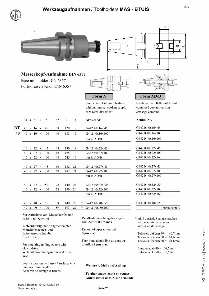
B16Werkzeugaufnahmen / Toolholders MAS - BT/JIS
Messerkopf-Aufnahme DIN 6357Face mill holder DIN 6357Porte-fraise à tenon DIN 6357
Form A Form AD/Bohne innere Kühlmittelzufuhr kombinierbare Kühlmittelzufuhrwithout internal coolant supply combined coolant versionsans refroidissement arrosage combiné
BT x d1 x A d2 L l3 Artikel-Nr. Artikel-Nr.
BT 40 x 16 x 45 38 128 17 G442 40x16x 45 G442D 40x16x 45
40 40 x 16 x 100 40 183 17 G442 40x16x100 G442D 40x16x100
nur in AD/B G442D 40x16x160
40 x 22 x 45 48 130 19 G442 40x22x 45 G442D 40x22x 4540 x 22 x 100 48 185 19 G442 40x22x100 G442D 40x22x10040 x 22 x 160 48 245 19 nur in AD/B G442D 40x22x160
40 x 27 x 45 60 132 21 G442 40x27x 45 G442D 40x27x 4540 x 27 x 100 60 187 21 G442 40x27x100 G442D 40x27x100
nur in AD/B G442D 40x27x160
40 x 32 x 50 78 140 24 G442 40x32x 50 G442D 40x32x 5040 x 32 x 100 78 190 24 G442 40x32x100 G442D 40x32x100
nur in AD/B G442D 40x32x160
40 x 40 x 55 89 148 27 * G442 40x40x 55 G442D 40x40x 5540 x 40 x 100 89 193 27 * G442 40x40x100 nur in Form A
Weitere A-Maße auf Anfrage
Further gauge length on requestAutres dimensions A sur demande
Rundlaufabweichung des Kegelszum Zapfen 8 µm max
Runout of taper to journal8 µm max
Faux-rond admissible du cone autourillon 8 µm max
* mit 4 zusätzl. Spannschraubenwith 4 additional screwsavec 4 vis de serrage
Teilkreis bei drm 40 = 66,7mmTeilkreis bei drm 50 = 101,6mmTeilkreis bei drm 60 = 101,6mm
Entraxe au Ø 40 = 66,7mmEntraxe au Ø 50 = 101,6mm
Zur Aufnahme von Messerköpfen undFräsern mit Quernut
Lieferumfang: mit 2 angeschraubtenMitnehmersteinen undFräseranzugsschraube(bis Drm 40)
For mounting milling cutters withclutch drive.With cutter-retaining-screw and drivekeys
Pour la fixation de fraises à surfacer et àrainures transversalesAvec vis de serrage et tenons
Bestell-Beispiel: G442 40x32x 50Order example: Seite 76
KL-T
ECH
s.r.
o | w
ww
.klte
.cz

B16 Werkzeugaufnahmen / Toolholders MAS - BT/JIS
Messerkopf-Aufnahme DIN 6357Face mill holder DIN 6357Porte-fraise à tenon DIN 6357
Form A Form AD/Bohne innere Kühlmittelzufuhr kombinierbare Kühlmittelzufuhrwithout internal coolant supply combined coolant versionsans refroidissement arrosage combiné
BT x d1 x A d2 L l3 Artikel-Nr. Artikel-Nr.
BT 50 x 16 x 100 39 219 17 G442 50x16x100 auf Anfrage nur in Form A50 50 x 16 x 160 39 279 17 G442 50x16x160 auf Anfrage nur in Form A
50 x 22 x 55 48 176 19 G442 50x22x 55 G442D 50x22x 5550 x 22 x 100 48 221 19 G442 50x22x100 G442D 50x22x10050 x 22 x 160 48 281 19 G442 50x22x160 nur in Form A50 x 22 x 200 48 321 19 G442 50x22x200 nur in Form A
50 x 27 x 55 60 178 21 G442 50x27x 55 G442D 50x27x 5550 x 27 x 100 58 223 21 G442 50x27x100 G442D 50x27x10050 x 27 x 160 55 283 21 G442 50x27x160 nur in Form A50 x 27 x 200 55 323 21 G442 50x27x200 nur in Form A
50 x 32 x 55 78 181 24 G442 50x32x 55 G442D 50x32x 5550 x 32 x 100 78 226 24 G442 50x32x100 G442D 50x32x10050 x 32 x 160 78 286 24 G442 50x32x160 nur in Form A50 x 32 x 200 78 326 24 G442 50x32x200 nur in Form A
50 x 40 x 55 89 184 27 * G442 50x40x 55 G442D 50x40x 5550 x 40 x 100 89 229 27 * G442 50x40x100 G442D 50x40x100
50 x 60 x 80 129 212 40 * G442 50x60x 80 nur in Form A
Zubehör /Accessories
G042 Seite / page 154G041 Seite / page 154
G055 Seite / page 159
Bestell-Beispiel: G442 50x40x 55Seite 77
KL-T
ECH
s.r.
o | w
ww
.klte
.cz

B16Werkzeugaufnahmen / Toolholders MAS - BT/JIS
Aufnahme für EinschraubfräserChuck for threaded type cutter gewuchtet /balanced / equilibré
Mandrin pour fraises à queue filetée auf G6,3 bei 15.000 U/min
Form AD/B kombinierbare Kühlmittelzufuhr
combined coolant version / arrosage combinéArtikel-Nummer
BT x Gewinde x A d2 L D d1
BT G447D 40 x M6 x 52 10 25 13 6,5
40 G447D 40 x M6 x 77 10 50 20 6,5G447D 40 x M6 x 102 10 75 23 6,5
G447D 40 x M8 x 52 13 25 15 8,5G447D 40 x M8 x 77 13 50 23 8,5G447D 40 x M8 x 102 13 75 23 8,5G447D 40 x M8 x 127 13 100 25 8,5
G447D 40 x M10 x 52 18 25 20 10,5G447D 40 x M10 x 77 18 50 23 10,5G447D 40 x M10 x 102 18 75 28 10,5G447D 40 x M10 x 127 18 100 32 10,5
G447D 40 x M12 x 52 21 25 24 12,5G447D 40 x M12 x 102 21 75 31 12,5G447D 40 x M12 x 152 21 125 36 12,5
G447D 40 x M16 x 52 29 25 29 17G447D 40 x M16 x 102 29 75 34 17G447D 40 x M16 x 152 29 125 40 17
Bestell-Beispiel: G447D 40x10x102Order example Seite 78
KL-T
ECH
s.r.
o | w
ww
.klte
.cz
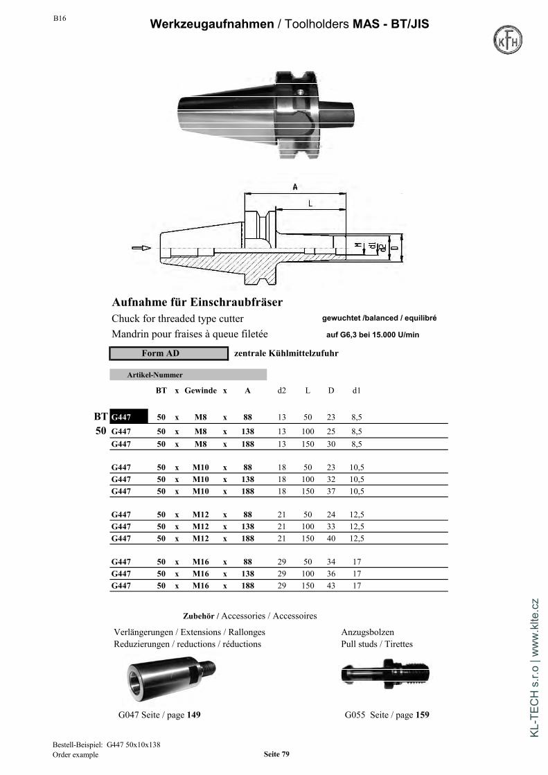
B16 Werkzeugaufnahmen / Toolholders MAS - BT/JIS
Aufnahme für EinschraubfräserChuck for threaded type cutter gewuchtet /balanced / equilibré
Mandrin pour fraises à queue filetée auf G6,3 bei 15.000 U/min
Form AD zentrale Kühlmittelzufuhr
Artikel-Nummer
BT x Gewinde x A d2 L D d1
BT G447 50 x M8 x 88 13 50 23 8,5
50 G447 50 x M8 x 138 13 100 25 8,5G447 50 x M8 x 188 13 150 30 8,5
G447 50 x M10 x 88 18 50 23 10,5G447 50 x M10 x 138 18 100 32 10,5G447 50 x M10 x 188 18 150 37 10,5
G447 50 x M12 x 88 21 50 24 12,5G447 50 x M12 x 138 21 100 33 12,5G447 50 x M12 x 188 21 150 40 12,5
G447 50 x M16 x 88 29 50 34 17G447 50 x M16 x 138 29 100 36 17G447 50 x M16 x 188 29 150 43 17
Zubehör / Accessories / Accessoires
Verlängerungen / Extensions / Rallonges AnzugsbolzenReduzierungen / reductions / réductions Pull studs / Tirettes
G047 Seite / page 149 G055 Seite / page 159
Bestell-Beispiel: G447 50x10x138Order example Seite 79
KL-T
ECH
s.r.
o | w
ww
.klte
.cz

B16Werkzeugaufnahmen / Toolholders MAS - BT/JIS
Einsatzhülsen für MK mit Lappen DIN 6383Morse taper adaptor for flat tangDouilles intermédiares cône morse
Form AD Form AD/BRundlaufabweichung max 10µm zentrale Kühlmittelzufuhr kombinierbare KühlmittelzufuhrMax runout: 10µm coolant through center combined coolant versionFaux-rond admissible: 10µm max. eau de refroid. centrale eau de refroidissement combiné
BT x MK x A D L Artikel-Nr. € / St. Artikel-Nr.
BT 30 x 1 x 45 25 93 G460 30x1x 45 46,90 nur in AD30 30 x 2 x 60 32 108 G460 30x2x 60 46,90 nur in AD
30 x 3 x 77 40 125 G460 30x3x 77 46,90 nur in AD
BT 40 x 1 x 50 25 116 G460 40x1x 50 32,00 G460D 40x1x 4540 40 x 2 x 50 32 116 G460 40x2x 50 32,00 G460D 40x2x 50
40 x 3 x 70 40 136 G460 40x3x 70 32,00 G460D 40x3x 7040 x 4 x 95 48 161 G460 40x4x 95 34,50 G460D 40x4x 95
BT 50 x 1 x 45 25 147 G460 50x1x 45 48,50 nur in AD50 50 x 2 x 50 32 152 G460 50x2x 50 48,50 nur in AD
50 x 3 x 65 40 167 G460 50x3x 65 48,50 nur in AD50 x 4 x 95 48 197 G460 50x4x 95 50,00 nur in AD50 x 5 x 105 63 207 G460 50x5x105 55,50 nur in AD
gewuchtet /balanced / equilibréauf G6,3 bei 15.000 U/min
Bestell-Beispiel: G460 40x2x50Order example: Seite 80
KL-T
ECH
s.r.
o | w
ww
.klte
.cz

B16 Werkzeugaufnahmen / Toolholders MAS - BT/JIS
Kurze Fräserhülsen für MK mit Gewinde DIN 6364Morse taper adaptor with draw threadDouilles intermédiares a cone morse a trou filete
Form Aohne innere Kühlmittelzufuhrwithout internal coolant supplysans refroidissement
Artikel-Nummer
BT x MK x A D L
BT G461 40 x 1 x 50 25 116 gewuchtet /balanced / equilibré40 G461 40 x 2 x 50 32 116 auf G6,3 bei 15.000 U/min
G461 40 x 3 x 70 40 136G461 40 x 4 x 95 48 161
Rundlaufabweichung max 10µmBT G461 50 x 1 x 45 25 147 Max runout: 10µm50 G461 50 x 2 x 60 32 162 Faux-rond admissible: 10µm max.
G461 50 x 3 x 65 40 167G461 50 x 4 x 90 48 192G461 50 x 5 x 110 63 212 Zubehör / Accessories
Anzugsbolzen / Pull studG055 Seite 159
Bestell-Beisp.: G461 40x3x70Order example Seite 81
KL-T
ECH
s.r.
o | w
ww
.klte
.cz

B16Werkzeugaufnahmen / Toolholders MAS - BT/JIS
Reduzierhülsen RohlingeReduction arbor Blank BarsDouilles de reduction Barreaux bruts
Artikel-Nummer Artikel-NummerBT x BT x A D L BT x D x A L
AussenInnen
G462 40 x 30 x 60 50 134 G499 40 x 63 x 250 316G462 40 x 40 x 100 70 176
G499 50 x 97 x 315 417G462 50 x 30 x 60 50 169 auf AnfrageG462 50 x 40 x 70 70 193G462 50 x 50 x 120 97 236
Mit eingebauter Innensechskantschraube bei Bestellung bitte Kegel und Bund gehärtet auf Vickershärte min. 630 HVjedesmal angeben, ob ein Werkzeug nach DIN 2080, DIN 69871 (min. 56 HRC). Kegel und Bund geschliffen.oder MAS-BT aufgenommen werden soll. Zylinderschaft D mit 25-35HRC zum Weiterbearbeiten.
With internal clamping screw. Please give information wether Shank and collar carbonized according to Vickers min. 630 HVyou want to reduce on a taper DIN2080, DIN69871 or MAS BT. (min. 56 HRC) and grinded.
Cylindrical Diameter D with 25-35HRC for further manufacturinAvec vis de serrage intérieure montée. Merci d'indiquer à lacommande si l'outil à monter est selon DIN2080, DIN69871 Cône d'outils et collerette trempés et rectifiés,ou MAS BT. queue D doux pour usinage ultérieur.
Zubehör / Accessories
Anzugsbolzen / Pull studG055 Seite 159
Bestell-Beisp.: G462 40x30x60 auf 2080Order example Seite 82
KL-T
ECH
s.r.
o | w
ww
.klte
.cz

B16 Werkzeugaufnahmen Morsekegel (MK) / Toolholders Morsetaper (MT)
Spannzangenfutter ER für SpaZa DIN 6499 Bohrfutteraufnahmen DIN 238Collet chuck ER / Syst. Regofix Taper shaftsMandrin à pinces / Syst. Regofix Cônes d'emmanchementArtikel-Nummer Artikel-Nummer
MKx ER A L D D x MK L
G510 2 x 16 45 109 32 M10 G531 6 x 1 83G510 2 x 25 65 130 42 M10 G531 6 x 2 100G510 3 x 25 56 137 42 M12 G531 10 x 0 79 auf AnfrageG510 3 x 32 70 151 50 M12 G531 10 x 1 86G510 4 x 25 63 165 42 M16 G531 10 x 2 105G510 4 x 32 65 168 50 M16 G531 12 x 0 84 auf AnfrageG510 4 x 40 95 198 63 M16 G531 12 x 1 89G510 5 x 40 86 215 63 M20 G531 12 x 2 106G510 5 x 50 112 242 78 M20 G531 12 x 3 125
G531 16 x 1 99G531 16 x 2 112G531 16 x 3 134G531 16 x 4 163G531 16 x 5 195 auf AnfrageG531 18 x 1 107G531 18 x 2 119G531 18 x 3 140G531 18 x 4 169G531 18 x 5 202
G531 22 x 2 130G531 22 x 3 147G531 22 x 4 176
Präzisionsbohrfutter MK mit Anzugs-Gewinde G531 22 x 5 213Precision-Drill chuck with thread G531 24 x 2 140Mandrin de perçage de précision à cône morse G531 24 x 3 157Artikel-Nummer Mit Schlüssel / with wrench G531 24 x 4 186
MKx d1 A l1 D G531 24 x 5 221
G534 2 x 0,3-8 76 79 36 M10G534 2 x 0,5-13 105 111 50 M10 Zubehör / AccessoriesG534 3 x 0,3-8 76 79 36 M12G534 3 x 0,5-13 105 111 50 M12G534 3 x 2,5-16 110 121 57 M12G534 4 x 0,5-13 110 116 50 M16G534 4 x 2,5-16 115 126 57 M16G534 5 x 0,5-13 112 118 50 M20 Aufsteck-Bohrkopf / drill-chuck-headG534 5 x 2,5-16 117 128 57 M20 Seite / page 153
Bestell-Beisp.: G510 MK3xER25Order example Seite 83
KL-T
ECH
s.r.
o | w
ww
.klte
.cz

B16Werkzeugaufnahmen Morsekegel (MK) / Toolholders Morsetaper (MT)
Kombi-Aufsteckdorn MK Gewinde DIN 6358 Aufsteckfräserdorne MK Gewinde DIN 6360
Combi shell mill holder MT with thread Milling Arbor tenon drive MT threadPorte-fraises à double usage CM avec filetage Porte fraise avec clavette
Artikel-Nummer Artikel-NummerMKx d1 A l1 l5 d2 MKx d1 A l3 d2 L
G540 2 x 13 43 22 12 28 M10 G541 2 x 10 43 16 20 123 M10 auf Anfrage
G540 2 x 16 43 27 17 32 M10 G541 2 x 16 43 30 28 137 M10 auf Anfrage
G540 2 x 22 43 31 19 40 M10 G541 2 x 22 43 40 36 147 M10 auf Anfrage
G540 3 x 13 48 22 12 28 M12 G541 3 x 13 48 25 24 154 M12 auf Anfrage
G540 3 x 16 48 27 17 32 M12 G541 3 x 16 48 30 28 159 M12 auf Anfrage
G540 3 x 22 48 31 19 40 M12 G541 3 x 22 48 40 36 169 M12 auf AnfrageG540 3 x 27 48 33 21 48 M12 G541 3 x 27 48 60 43 189 M12 auf AnfrageG540 3 x 32 48 38 24 58 M12 G541 3 x 32 48 60 48 189 M12 auf Anfrage
G540 4 x 13 55 22 12 28 M16 auf Anfrage G541 4 x 16 55 30 28 187 M16 auf AnfrageG540 4 x 16 55 27 17 32 M16 G541 4 x 22 55 40 36 197 M16 auf AnfrageG540 4 x 22 55 31 19 40 M16 G541 4 x 27 55 60 43 217 M16 auf AnfrageG540 4 x 27 55 33 21 48 M16 G541 4 x 32 55 60 48 217 M16 auf AnfrageG540 4 x 32 55 38 24 58 M16 G541 4 x 40 55 60 56 217 M16 auf AnfrageG540 4 x 40 55 41 27 70 M16
G541 5 x 16 60 30 28 219 M20 auf AnfrageG540 5 x 16 75 27 17 32 M20 G541 5 x 22 60 40 36 229 M20 auf AnfrageG540 5 x 27 75 33 21 48 M20 G541 5 x 27 60 60 43 249 M20 auf AnfrageG540 5 x 32 75 38 24 58 M20 G541 5 x 32 60 60 48 249 M20 auf AnfrageG540 5 x 40 75 41 27 70 M20 G541 5 x 50 60 60 70 249 M20 auf AnfrageG540 5 x 50 75 46 30 90 M20 auf Anfrage
Die Morsekegel-Aufnahmen auf dieser Seite sind nur bedingt ab Lager lieferbarThe morsetaper holders on this page are no stock standardLes porte-fraises CM ne sont pas stockés en permanence
Zubehör / Accessories
G040 Seite/page 154 G041 Seite/page 154 Einschraubbare MitnehmerlappenTangs to screw in Seite/page 160
G042 Seite/page 154 Gonds aplatis vissables
Bestell-Beisp.: G540 4x22Order example Seite 84
KL-T
ECH
s.r.
o | w
ww
.klte
.cz

B16
Werkzeugaufnahmen Morsekegel (MK) / Toolholders Morsetaper (MT)
Lange Fräserdorne mit Gewinde /Milling arbor long DIN 2081 / 2086Mandrin de fraisage long, avec filetage
Artikel-Nummer MK d1 l1 L Form A Form B
G550 3x13x160 3 13 160 280 auf Anfrage auf AnfrageG550 3x16x200 3 16 200 322 auf Anfrage auf AnfrageG550 3x16x250 3 16 250 372 auf Anfrage auf AnfrageG550 3x16x315 3 16 315 437 auf AnfrageG550 3x16x400 3 16 400 522 auf AnfrageG550 3x22x500 3 22 500 628G550 3x27x250 3 27 250 384G550 3x27x315 3 27 315 449G550 3x27x400 3 27 400 534G550 3x27x500 3 27 500 634G550 3x32x315 3 32 315 453
G550 4x16x315 4 16 315 465G550 4x16x400 4 16 400 550G550 4x22x315 4 22 315 471G550 4x22x400 4 22 400 556G550 4x22x500 4 22 500 656G550 4x27x250 4 27 250 412G550 4x27x315 4 27 315 477G550 4x27x400 4 27 400 562 auf Anfrage auf AnfrageG550 4x27x500 4 27 500 662 auf Anfrage auf AnfrageG550 4x27x630 4 27 630 792G550 4x32x315 4 32 315 481G550 4x32x400 4 32 400 566 auf Anfrage auf AnfrageG550 4x32x500 4 32 500 666 auf Anfrage auf AnfrageG550 4x32x630 4 32 630 796G550 4x40x500 4 40 500 674 auf Anfrage auf AnfrageG550 4x40x630 4 40 630 804
G550 5x22x315 5 22 315 503 auf Anfrage auf AnfrageG550 5x22x630 5 22 630 818G550 5x27x315 5 27 315 503G550 5x27x400 5 27 400 594G550 5x27x500 5 27 500 694G550 5x32x630 5 32 630 828G550 5x40x400 5 40 400 606G550 5x40x800 5 40 800 1006 auf Anfrage auf AnfrageG550 5x50x400 5 50 400 612 auf Anfrage auf AnfrageG550 5x50x500 5 50 500 712G550 5x50x630 5 50 630 842
Zubehör s.S. 150 - 152Accessories page 150 -152
Lagerabverkauf - sollte eine Abmessung vergriffen sein erfolgt keine NeuauflageLiquidation du stock, si une dimension n'est plus disponible, elle ne sera pas remise en production
Form A:Fräserdorn mit Mutterund Passfeder
Form B:Fräserdorn mit Mutter,Ringsatz und Passfeder
Bestell-Beispiel: G550 4x22x250 FormAOrder example Seite 85
KL-T
ECH
s.r.
o | w
ww
.klte
.cz

B16Werkzeugaufnahmen Morsekegel (MK) / Toolholders Morsetaper (MT)
Reduzierhülsen DIN 2185 MK Verlängerungshülsen DIN 2187Reduction arbor DIN 2185 Morse taper extension DIN 2187Douilles de réduction DIN 2185 Rallonge cône morse DIN 2187FormA:Austreiblappen gehärtet FormA:Austreiblappen gehärtet Gond aplati trempé
Aussenkegel geschliffen Aussenkegel geschliffen Cône extérieur rectifi
Artikel-Nummer Artikel-Nummer
Aussen Innen Aussen InnenMK x MK L MK x MK L
G562 4 x 1 124 auf Anfrage G564 1 x 2 160 auf Anfrage
G562 4 x 2 124 auf Anfrage G564 2 x 1 160 auf AnfrageG564 3 x 1 175 auf Anfrage
G562 5 x 1 156 auf Anfrage G564 4 x 1 200 auf Anfrage
G562 5 x 2 156 auf Anfrage G564 5 x 2 247 auf Anfrage
G562 5 x 3 156 auf Anfrage G564 5 x 3 268 auf Anfrage
Form A: Lagerabverkauf Forme A: liquidation du stock
FormB:Ganz gehärtet/Innen- und FormB:Ganz gehärtet/Innen- undAussenkegel geschliffen Aussenkegel geschliffen
Entièrement trempée/cône intérieur et Entièrement trempée/cône intérieur etextérieur rectifié extérieur rectifié
G562B 1 x 0 80 G564B 1 x 1 145G564B 1 x 2 160
G562B 2 x 1 92 G564B 2 x 1 160G564B 2 x 2 175
G562B 3 x 1 99 G564B 2 x 3 196G562B 3 x 2 98 G564B 3 x 1 175
G564B 3 x 2 195G562B 4 x 1 124 G564B 3 x 3 215G562B 4 x 2 124 G564B 3 x 4 240G562B 4 x 3 132 G564B 4 x 1 200
G564B 4 x 2 215G562B 5 x 1 156 G564B 4 x 3 240G562B 5 x 2 156 G564B 4 x 4 265G562B 5 x 3 156 G564B 4 x 5 300G562B 5 x 4 171 G564B 5 x 2 247
G564B 5 x 3 268G562B 6 x 3 218 G564B 5 x 4 300G562B 6 x 4 218 G564B 5 x 5 335G562B 6 x 5 218
Bestell-Beisp.: G564 B 5x4Order example Seite 86
KL-T
ECH
s.r.
o | w
ww
.klte
.cz
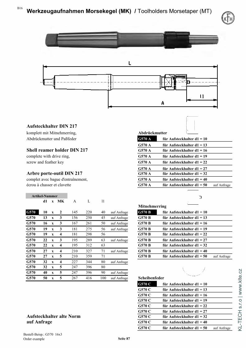
B16 Werkzeugaufnahmen Morsekegel (MK) / Toolholders Morsetaper (MT)
Aufsteckhalter DIN 217komplett mit Mitnehmerring, AbdrückmutterAbdrückmutter und Paßfeder G570 A für Aufsteckhalter d1 = 10
G570 A für Aufsteckhalter d1 = 13Shell reamer holder DIN 217 G570 A für Aufsteckhalter d1 = 16complete with drive ring, G570 A für Aufsteckhalter d1 = 19screw and feather key G570 A für Aufsteckhalter d1 = 22
G570 A für Aufsteckhalter d1 = 27Arbre porte-outil DIN 217 G570 A für Aufsteckhalter d1 = 32complet avec bague d'entraînement, G570 A für Aufsteckhalter d1 = 40écrou à chasser et clavette G570 A für Aufsteckhalter d1 = 50 auf Anfrage
Artikel-Nummerd1 x MK A L l1
MitnehmerringG570 10 x 2 145 220 40 auf Anfrage G570 B für Aufsteckhalter d1 = 10G570 13 x 3 156 250 45 auf Anfrage G570 B für Aufsteckhalter d1 = 13G570 16 x 3 167 261 50 auf Anfrage G570 B für Aufsteckhalter d1 = 16G570 19 x 3 181 275 56 auf Anfrage G570 B für Aufsteckhalter d1 = 19G570 19 x 4 181 298 56 G570 B für Aufsteckhalter d1 = 22G570 22 x 3 195 289 63 auf Anfrage G570 B für Aufsteckhalter d1 = 27G570 22 x 4 195 312 63 G570 B für Aufsteckhalter d1 = 32G570 27 x 4 210 327 71 auf Anfrage G570 B für Aufsteckhalter d1 = 40G570 27 x 5 210 359 71 G570 B für Aufsteckhalter d1 = 50 auf AnfrageG570 32 x 4 227 344 80 auf AnfrageG570 32 x 5 247 396 80G570 40 x 5 247 396 90 auf AnfrageG570 50 x 5 267 416 100 auf Anfrage Scheibenfeder
G570 C für Aufsteckhalter d1 = 10G570 C für Aufsteckhalter d1 = 13G570 C für Aufsteckhalter d1 = 16G570 C für Aufsteckhalter d1 = 19G570 C für Aufsteckhalter d1 = 22G570 C für Aufsteckhalter d1 = 27
Aufsteckhalter alte Norm G570 C für Aufsteckhalter d1 = 32auf Anfrage G570 C für Aufsteckhalter d1 = 40
G570 C für Aufsteckhalter d1 = 50 auf Anfrage
Bestell-Beisp.: G570 16x3Order example Seite 87
KL-T
ECH
s.r.
o | w
ww
.klte
.cz
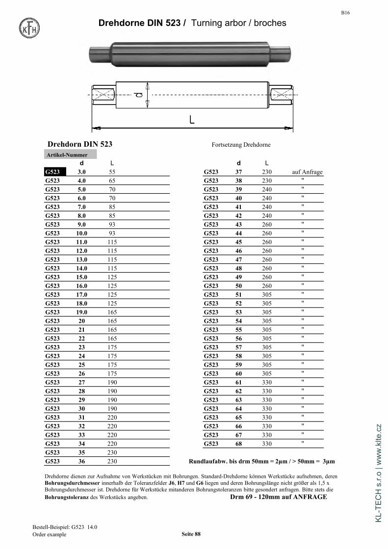
B16
Drehdorne DIN 523 / Turning arbor / broches
Drehdorn DIN 523 Fortsetzung DrehdorneArtikel-Nummer
d L d LG523 3.0 55 G523 37 230 auf AnfrageG523 4.0 65 G523 38 230 "G523 5.0 70 G523 39 240 "G523 6.0 70 G523 40 240 "G523 7.0 85 G523 41 240 "G523 8.0 85 G523 42 240 "G523 9.0 93 G523 43 260 "G523 10.0 93 G523 44 260 "G523 11.0 115 G523 45 260 "G523 12.0 115 G523 46 260 "G523 13.0 115 G523 47 260 "G523 14.0 115 G523 48 260 "G523 15.0 125 G523 49 260 "G523 16.0 125 G523 50 260 "G523 17.0 125 G523 51 305 "G523 18.0 125 G523 52 305 "G523 19.0 165 G523 53 305 "G523 20 165 G523 54 305 "G523 21 165 G523 55 305 "G523 22 165 G523 56 305 "G523 23 175 G523 57 305 "G523 24 175 G523 58 305 "G523 25 175 G523 59 305 "G523 26 175 G523 60 305 "G523 27 190 G523 61 330 "G523 28 190 G523 62 330 "G523 29 190 G523 63 330 "G523 30 190 G523 64 330 "G523 31 220 G523 65 330 "G523 32 220 G523 66 330 "G523 33 220 G523 67 330 "G523 34 220 G523 68 330 "G523 35 230G523 36 230 Rundlaufabw. bis drm 50mm = 2µm / > 50mm = 3µm
Drehdorne dienen zur Aufnahme von Werkstücken mit Bohrungen. Standard-Drehdorne können Werkstücke aufnehmen, derenBohrungsdurchmesser innerhalb der Toleranzfelder J6, H7 und G6 liegen und deren Bohrungslänge nicht größer als 1,5 xBohrungsdurchmesser ist. Drehdorne für Werkstücke mitanderen Bohrungstoleranzen bitte gesondert anfragen. Bitte stets dieBohrungstoleranz des Werkstücks angeben. Drm 69 - 120mm auf ANFRAGE
Bestell-Beispiel: G523 14.0Order example Seite 88
KL-T
ECH
s.r.
o | w
ww
.klte
.cz

B16
Schleifdorne DIN 6374 / Grinding arbor / broches de meulage
Schleifdorne DIN 6374 Fortsetzung SchleifdorneArtikel-Nummer
d L d LG524 3.0 71 G524 37 300G524 4.0 71 G524 38 300G524 5.0 71 G524 39 300G524 6.0 71 G524 40 300G524 7.0 100 G524 41 300G524 8.0 100 G524 42 300G524 9.0 100 G524 43 300G524 10.0 100 G524 44 300G524 11.0 140 G524 45 300G524 12.0 140 G524 46 300G524 13.0 140 G524 47 300G524 14.0 140 G524 48 300G524 15.0 140 G524 49 300 auf AnfrageG524 16.0 140 G524 50 300 "G524 17.0 140 G524 52 380 "G524 18.0 140 G524 53 380 "G524 19.0 220 G524 54 380 "G524 20 220 G524 55 380 "G524 21 220 G524 56 380 "G524 22 220 G524 58 380 "G524 23 220 G524 59 380 "G524 24 220 G524 60 380 "G524 25 220 G524 61 380 "G524 26 220 G524 62 380 "G524 27 220 G524 63 380 "G524 28 220 G524 64 380 "G524 29 220 drm 65 - 120 auf AnfrageG524 30 300 Material = 16MnCr5G524 31 300G524 32 300G524 33 300G524 34 300G524 35 300G524 36 300
Auf Wunsch kann das Toleranzfeld der aufzunehmenden Bohrung auch auf 2 Dorne verteilt werden.Bitte stets die Bohrungstoleranz des Werkstücks angeben.
Schleifdorne dienen zur Aufnahme von Werkstückenmit Bohrungen. Die aufnehmbare Bohrungslänge desWerkstückes ist abhängig vom Nenndurchmesser d:d bis 24 => Bohrungslänge bis 2 x dd über 24 bis 50 => Bohrungslänge bis 1,5 x dd über 50 => Bohrungslänge bis 1 x d
Bestell-Beispiel: G524 14.0 H7Order example Seite 89
KL-T
ECH
s.r.
o | w
ww
.klte
.cz

B16Werkzeugaufnahmen / Toolholders HSK DIN 69893
Spannzangenfutter ER für Spannzangen DIN 6499Collet chuck ER / Syst. Regofix for collets DIN 6499 gewuchtet / balanced / equilibré
Mandrin à pinces / Syst. Regofix pour pinces DIN 6499 auf G6,3 bei 20.000 U/min
Form AD zentrale Kühlmittelzufuhrcoolant through centerarrosage central
Artikel-NummerER x A L D
G610A40 16 x 80 100 28HSK G610A40 25 x 80 100 42A40 G610A40 32 x 100 120 50
G610A50 16 x 100 125 28HSK G610A50 25 x 100 125 42A50 G610A50 32 x 100 125 50
Rundlaufabweichung: HSK zu Innenkegel 5 µm max. HSK-F63 / HSK-E40Accuracy: taper to inner cone 5µm max. Auf Anfrage / on requestPrecision: défaut de concentricité admissible du cône au tenon 5µm
Zubehör / Accessories
G023 Seite 148 G020 Seite 142ff G024 Seite 148 G065 Seite 160
Lieferumfang / Including:mit Spannmutter DIN6499with Collet-Nut DIN6499avec ecrou de serrage DIN6499
ER-Spannbereiche:ER-Clamping-Range:ER-Plage de serrage
ER16 = 1 - 10 mmER25 = 2 - 16 mmER32 = 2 - 20 mmER40 = 4 - 30 mm
Bestell-Beisp.: G 610A50 x ER32x100Order example: Seite 90
KL-T
ECH
s.r.
o | w
ww
.klte
.cz
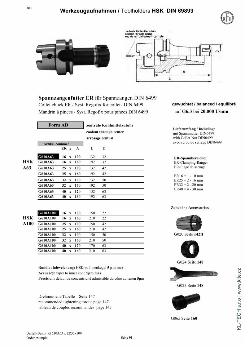
B16 Werkzeugaufnahmen / Toolholders HSK DIN 69893
Spannzangenfutter ER für Spannzangen DIN 6499Collet chuck ER / Syst. Regofix for collets DIN 6499 gewuchtet / balanced / equilibré
Mandrin à pinces / Syst. Regofix pour pinces DIN 6499 auf G6,3 bei 20.000 U/min
Form AD zentrale Kühlmittelzufuhrcoolant through centerarrosage central
Artikel-NummerER x A L D
G610A63 16 x 100 132 32HSK G610A63 16 x 160 192 32A63 G610A63 25 x 100 132 42
G610A63 25 x 160 192 42G610A63 32 x 100 132 50G610A63 32 x 160 192 50G610A63 40 x 120 152 63G610A63 40 x 160 192 63
Zubehör / AccessoriesG610A100 16 x 100 150 22
HSK G610A100 16 x 160 210 22A100 G610A100 25 x 100 150 42
G610A100 25 x 160 210 42G610A100 32 x 100 150 50 G020 Seite 142ffG610A100 32 x 160 210 50G610A100 40 x 120 170 63G610A100 40 x 160 210 63
G024 Seite 148Rundlaufabweichung: HSK zu Innenkegel 5 µm max.Accuracy: taper to inner cone 5µm max.Precision: défaut de concentricité admissible du cône au tenon 5µm
G023 Seite 148
Drehmoment-Tabelle Seite 147recommended tightening torque page 147tableau de couples recommandes page 147
G065 Seite 160
Lieferumfang / Including:mit Spannmutter DIN6499with Collet-Nut DIN6499avec ecrou de serrage DIN6499
ER-Spannbereiche:ER-Clamping-Range:ER-Plage de serrage
ER16 = 1 - 10 mmER25 = 2 - 16 mmER32 = 2 - 20 mmER40 = 4 - 30 mm
Bestell-Beisp.: G 610A63 x ER32x100Order example: Seite 91
KL-T
ECH
s.r.
o | w
ww
.klte
.cz

B16Werkzeugaufnahmen / Toolholders HSK DIN 69893
Hydro-DehnspannfutterHydraulic chuck gewuchtet / balanced / equilibréMandrins hydraulique auf G2,5 bei 20.000 U/min
Form AD zentrale Kühlmittelzufuhr Rundlaufabweichung: 3 µm max.
coolant through center Accuracy: run-out 3µm max.arrosage central Precision: Faux-rond admissible max 3µm
Artikel-Nummerd1 x A L D D1
G614A63 6 x 70 102 50 26 auf Anfrage Zubehör / AccessoriesG614A63 8 x 70 102 50 28 auf AnfrageG614A63 10 x 80 112 50 30 auf AnfrageG614A63 12 x 85 117 50 32G614A63 16 x 90 122 50 38G614A63 20 x 80 112 57 33 *G614A63 20 x 90 122 50 42 Reduzierbüchsen fürG614A63 25 x 120 152 53 57 Hydrodehn-SpannfutterG614A63 32 x 125 157 59 63 Collet for hydraulic chuck
Douilles de réduction pourmandrins hydrauliques
G614A100 10 x 90 140 50 30 auf Anfrage G014a Seite/page 141G614A100 12 x 95 145 50 32 auf AnfrageG614A100 16 x 100 150 50 38 auf AnfrageG614A100 20 x 105 155 50 42G614A100 25 x 115 165 57 63G614A100 32 x 120 170 63 67
Mit Schlüssel / with wrench / avec clé de serrage KühlmittelrohrCoolant tube
Drehzahl max. 40.000 U/min erfordert Feinwuchten Tube d'arrosageMax. 40.000 rpm requires fine-balancing G065 Seite 160Max. 40.000 rpm nécessitent un équilibrage fin
* Ausführung kurz / schwerHandhabung: Auf keinen Fall ohne eingeführtes Werkzeug spannen. short and heavy versionUsage: never clamp when there is no tooling inserted in the bore version courte et lourdeUtilisation: ne jamais serrer sans outil inséré
Tabelle mit den übertragbaren Drehmomenten siehe Seite 94
Bestell-Beisp.: G 614A63 20x90Order example Seite 92
KL-T
ECH
s.r.
o | w
ww
.klte
.cz

B16 Werkzeugaufnahmen / Toolholders HSK DIN 69893
Kraftspannfutter High Power milling Chuck Mandrin a fort serrage
Form AD
Artikel-Nummerd x L L1 D1 D
G618A63 20 x 100 23 49 46G618A63 20 x 150 23 49 46 Zubehör / Accessories
G618A63 32 x 113 33 68 67G618A63 32 x 150 33 68 67
Reduzierbüchsen für Kraft-Spannfutter
Rundlaufabweichung: 4 µm max. bei 3 x d1 Collet for high power milling chuckRuhiger Lauf - geringe Vibrationen - hohe Steifigkeit Douilles de réduction pour Hohes Klemmdrehmoment durch maximalen Anlage-Kontakt mandrins à fort serrageHandhabung: Für Werkzeuge mit Schafttoleranz h6 G014a Seite/page 141Schneide des Werkzeugs nicht in die Aufnahmeborung d1 einführenGewuchtet G2,5 bei 20.000 U/minLieferumfang: MIT Schlüssel
Accuracy: run-out 4 µm max. at 3 x d1Smooth rotations, less vibrations, very rigidUsage: for toolings with shaft tolerance h6Do only insert shafts - not cutting edges in bore d1Balanced G2,5 at 20.000 rpmScope of delivery: WITH wrench
Défaut de concentricité: 4 µm max. à 3 x d1Fonctionnement stable - peu de vibrations - grande rigiditéImportant couple de serrage grâce à un contact d'adhérence maximalUtilisation: ne jamais serrer sans outil inséréNe pas introduire l'arête coupante de l'outil dans le perçage d1Equilibré a G2,5 20.000 rpmLivraison : AVEC clé
Bestell-Beisp.: G615A63 20x95Order example Seite 93
KL-T
ECH
s.r.
o | w
ww
.klte
.cz

B16Technische Information / technical information
Hydro-Dehnspannfutter / Hydraulic chucks
Spann- Mindest- Mindest- zul. Übertragbaresdurchmesser umdrehungen einspanntiefe Drehmoment
Clamping Minimum Minimum Transferablediameter turns clamping torque
of screw depth
6mm 2 27mm 20Nm
8mm 2 27mm 35Nm
10mm 3 31mm 45Nm
12mm 3,5 36mm 80Nm
14mm 4 36mm 100Nm
16mm 4,5 39mm 130Nm
18mm 5 39mm 180Nm
20mm 5 41mm 210Nm
25mm 6 47mm 350Nm
32mm 6 51mm 450Nm
Hydro-Dehnspannfutter entsprechen der DIN 69882-7. Sie bieten beisachgemäßen Umgang beste Rundlauf- und Wiederholgenauigkeit.Durch den Einsatz von Reduzierhülsen vielfältig einsetzbar.( zul. Übertragbare Drehmomente siehe oben ).Optimale Betriebstemperatur 20-50°C
Hydraulic chucks are manufactured due to DIN69882-7They show a good- run-out performance, a good repeatabilityand high transferable torques ( see above)
Seite 94
KL-T
ECH
s.r.
o | w
ww
.klte
.cz
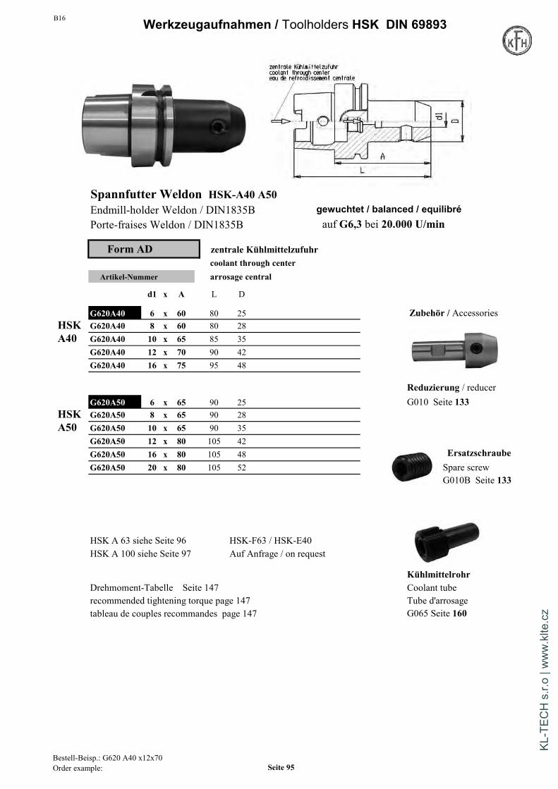
B16 Werkzeugaufnahmen / Toolholders HSK DIN 69893
Spannfutter Weldon HSK-A40 A50Endmill-holder Weldon / DIN1835B gewuchtet / balanced / equilibréPorte-fraises Weldon / DIN1835B auf G6,3 bei 20.000 U/min
Form AD zentrale Kühlmittelzufuhrcoolant through center
Artikel-Nummer arrosage central
d1 x A L D
G620A40 6 x 60 80 25 Zubehör / AccessoriesHSK G620A40 8 x 60 80 28A40 G620A40 10 x 65 85 35
G620A40 12 x 70 90 42G620A40 16 x 75 95 48
Reduzierung / reducerG620A50 6 x 65 90 25 G010 Seite 133
HSK G620A50 8 x 65 90 28A50 G620A50 10 x 65 90 35
G620A50 12 x 80 105 42G620A50 16 x 80 105 48 ErsatzschraubeG620A50 20 x 80 105 52 Spare screw
G010B Seite 133
HSK A 63 siehe Seite 96 HSK-F63 / HSK-E40HSK A 100 siehe Seite 97 Auf Anfrage / on request
KühlmittelrohrDrehmoment-Tabelle Seite 147 Coolant tuberecommended tightening torque page 147 Tube d'arrosagetableau de couples recommandes page 147 G065 Seite 160
Bestell-Beisp.: G620 A40 x12x70Order example: Seite 95
KL-T
ECH
s.r.
o | w
ww
.klte
.cz
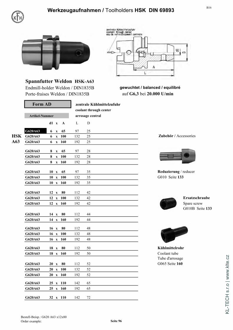
B16Werkzeugaufnahmen / Toolholders HSK DIN 69893
Spannfutter Weldon HSK-A63Endmill-holder Weldon / DIN1835B gewuchtet / balanced / equilibréPorte-fraises Weldon / DIN1835B auf G6,3 bei 20.000 U/min
Form AD zentrale Kühlmittelzufuhrcoolant through center
Artikel-Nummer arrosage central
d1 x A L D
G620A63 6 x 65 97 25HSK G620A63 6 x 100 132 25 Zubehör / AccessoriesA63 G620A63 6 x 160 192 25
G620A63 8 x 65 97 28G620A63 8 x 100 132 28G620A63 8 x 160 192 28
G620A63 10 x 65 97 35 Reduzierung / reducerG620A63 10 x 100 132 35 G010 Seite 133G620A63 10 x 160 192 35
G620A63 12 x 80 112 42G620A63 12 x 100 132 42 ErsatzschraubeG620A63 12 x 160 192 42 Spare screw
G010B Seite 133G620A63 14 x 80 112 44G620A63 14 x 160 192 44
G620A63 16 x 80 112 48G620A63 16 x 100 132 48G620A63 16 x 160 192 48
G620A63 18 x 80 112 50 KühlmittelrohrG620A63 18 x 160 192 50 Coolant tube
Tube d'arrosageG620A63 20 x 80 112 52 G065 Seite 160G620A63 20 x 100 132 52G620A63 20 x 160 192 52
G620A63 25 x 110 142 65G620A63 25 x 160 192 65
G620A63 32 x 110 142 72
Bestell-Beisp.: G620 A63 x12x80Order example: Seite 96
KL-T
ECH
s.r.
o | w
ww
.klte
.cz

B16 Werkzeugaufnahmen / Toolholders HSK DIN 69893
Spannfutter Weldon HSK-A100Endmill-holder Weldon / DIN1835B gewuchtet / balanced / equilibréPorte-fraises Weldon / DIN1835B auf G6,3 bei 20.000 U/min
Form AD zentrale Kühlmittelzufuhrcoolant through center
Artikel-Nummer arrosage central
d1 x A L D
G620A100 6 x 80 130 25HSK G620A100 6 x 160 210 25 Zubehör / AccessoriesA100
G620A100 8 x 80 130 28G620A100 8 x 160 210 28
G620A100 10 x 80 130 35G620A100 10 x 160 210 35
Reduzierung / reducerG620A100 12 x 80 130 42 G010 Seite 133G620A100 12 x 160 210 42
G620A100 14 x 80 130 44
G620A100 16 x 100 150 48G620A100 16 x 160 210 48 Ersatzschraube
Spare screwG620A100 18 x 100 150 50 G010B Seite 133
G620A100 20 x 100 150 52G620A100 20 x 160 210 52
G620A100 25 x 100 150 65G620A100 25 x 160 210 65
KühlmittelrohrG620A100 32 x 100 150 72 Coolant tube
Tube d'arrosageG620A100 40 x 105 155 80 G065 Seite 160
Drehmoment-Tabelle Seite 147 HSK A 40 siehe Seite 97recommended tightening torque page 147 HSK A 50 siehe Seite 97tableau de couples recommandes page 147
Bestell-Beisp.: G620 A100 x10x 90Order example: Seite 97
KL-T
ECH
s.r.
o | w
ww
.klte
.cz
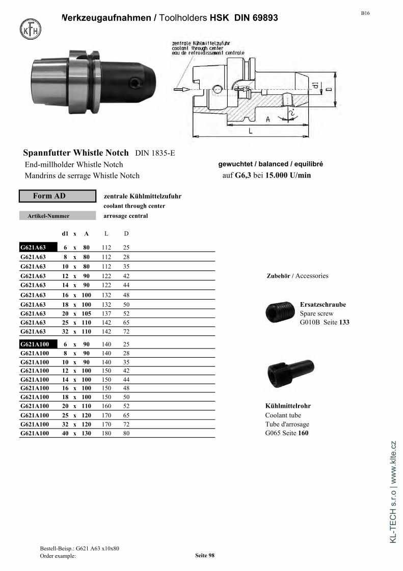
B16Werkzeugaufnahmen / Toolholders HSK DIN 69893
Spannfutter Whistle Notch DIN 1835-EEnd-millholder Whistle Notch gewuchtet / balanced / equilibréMandrins de serrage Whistle Notch auf G6,3 bei 15.000 U/min
Form AD zentrale Kühlmittelzufuhrcoolant through center
Artikel-Nummer arrosage central
d1 x A L D
G621A63 6 x 80 112 25G621A63 8 x 80 112 28G621A63 10 x 80 112 35G621A63 12 x 90 122 42 Zubehör / AccessoriesG621A63 14 x 90 122 44G621A63 16 x 100 132 48G621A63 18 x 100 132 50 ErsatzschraubeG621A63 20 x 105 137 52 Spare screwG621A63 25 x 110 142 65 G010B Seite 133G621A63 32 x 110 142 72
G621A100 6 x 90 140 25G621A100 8 x 90 140 28G621A100 10 x 90 140 35G621A100 12 x 100 150 42G621A100 14 x 100 150 44G621A100 16 x 100 150 48G621A100 18 x 100 150 50G621A100 20 x 110 160 52 KühlmittelrohrG621A100 25 x 120 170 65 Coolant tubeG621A100 32 x 120 170 72 Tube d'arrosageG621A100 40 x 130 180 80 G065 Seite 160
Bestell-Beisp.: G621 A63 x10x80Order example: Seite 98
KL-T
ECH
s.r.
o | w
ww
.klte
.cz

B16 Werkzeugaufnahmen / Toolholders HSK DIN 69893
Gewindeschneid-Schnellwechselfutter mit Längenausgleich auf Zug und DruckQuick change tapping chuck with compens.Appareil à tarauder avec compensation de longueur. Zubehör / Accessories
Artikel-Nummer mit KupplungGröße A d D L avec coupleur
G617A63 1 102 19 38 134 with clutchG617A63 2 152 31 54 184 G013 mit Seite 139
G617A100 1 112 19 38 162 auf Anfrage ohne KupplungG617A100 2 100 31 54 150 auf Anfrage sans coupleurG617A100 3 144 48 86 194 auf Anfrage without clutch
G013 ohne Seite 139
Spannfutter mit Kühlmittelnuten DIN 1835-B
Endmill holder with coolant grooves Drehmoment-Tabelle Seite 147Porte-fraises Weldon / DIN1835B rainures d'arrosage recommended tightening torque page 147
tableau de couples recommandes page 147Form AD
Artikel-Nummer
d1 A L D gewuchtet / balanced / equilibréauf G6,3 bei 20.000 U/min
G623A63 6 65 97 25
G623A63 8 65 97 28G623A63 10 65 97 35 Zubehör / AccessoriesG623A63 12 80 112 42G623A63 14 80 112 44G623A63 16 80 112 48G623A63 18 80 112 50G623A63 20 80 112 52G623A63 25 110 142 65 KühlmittelrohrG623A63 32 110 142 72 Coolant tubeG623A63 40 125 157 80 Tube d'arrosage
G065 Seite 160
Bestell-Beisp.: G623 A63 10Order example: Seite 99
KL-T
ECH
s.r.
o | w
ww
.klte
.cz
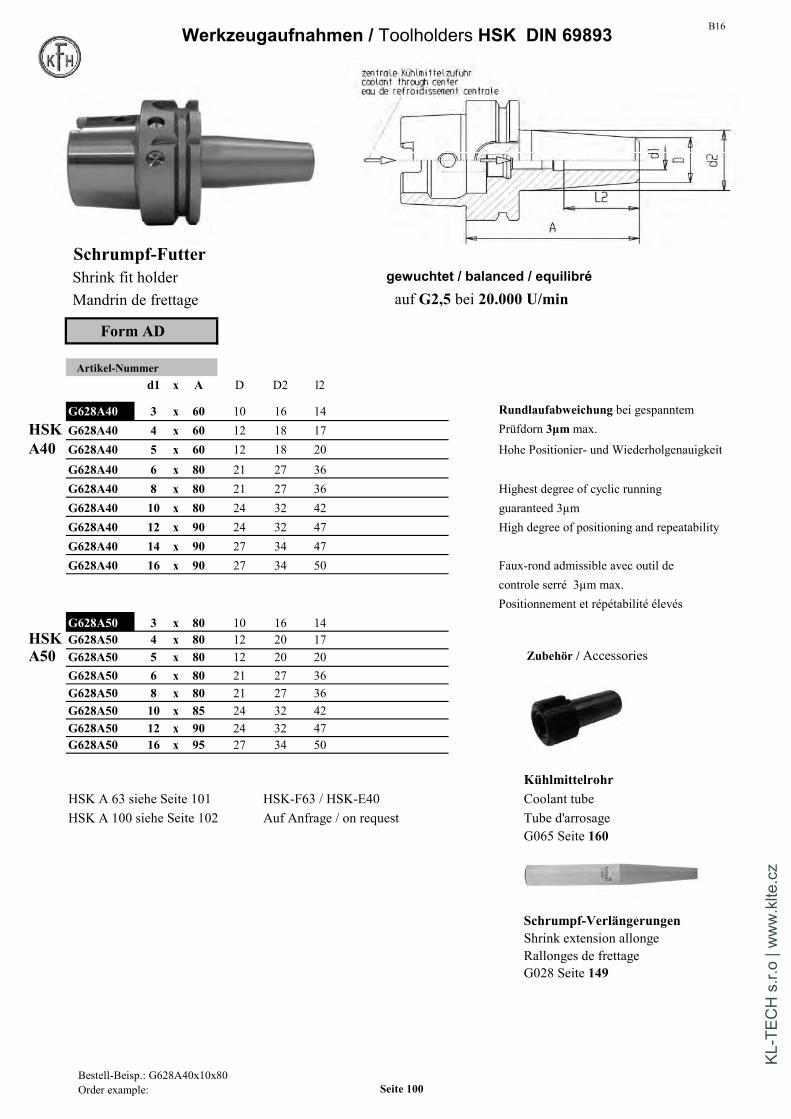
B16Werkzeugaufnahmen / Toolholders HSK DIN 69893
Schrumpf-FutterShrink fit holder gewuchtet / balanced / equilibréMandrin de frettage auf G2,5 bei 20.000 U/min
Form AD
Artikel-Nummerd1 x A D D2 l2
G628A40 3 x 60 10 16 14 Rundlaufabweichung bei gespanntem
HSK G628A40 4 x 60 12 18 17 Prüfdorn 3µmmax.
A40 G628A40 5 x 60 12 18 20 Hohe Positionier- und WiederholgenauigkeitG628A40 6 x 80 21 27 36G628A40 8 x 80 21 27 36 Highest degree of cyclic runningG628A40 10 x 80 24 32 42 guaranteed 3µmG628A40 12 x 90 24 32 47 High degree of positioning and repeatabilityG628A40 14 x 90 27 34 47G628A40 16 x 90 27 34 50 Faux-rond admissible avec outil de
controle serré 3µm max.Positionnement et répétabilité élevés
G628A50 3 x 80 10 16 14HSK G628A50 4 x 80 12 20 17A50 G628A50 5 x 80 12 20 20 Zubehör / Accessories
G628A50 6 x 80 21 27 36G628A50 8 x 80 21 27 36G628A50 10 x 85 24 32 42G628A50 12 x 90 24 32 47G628A50 16 x 95 27 34 50
KühlmittelrohrHSK A 63 siehe Seite 101 HSK-F63 / HSK-E40 Coolant tubeHSK A 100 siehe Seite 102 Auf Anfrage / on request Tube d'arrosage
G065 Seite 160
Schrumpf-VerlängerungenShrink extension allongeRallonges de frettageG028 Seite 149
Bestell-Beisp.: G628A40x10x80Order example: Seite 100
KL-T
ECH
s.r.
o | w
ww
.klte
.cz
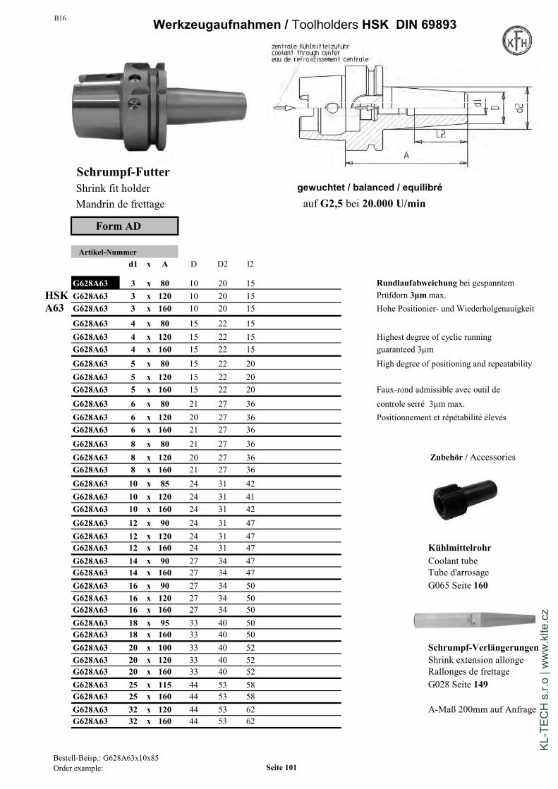
B16 Werkzeugaufnahmen / Toolholders HSK DIN 69893
Schrumpf-FutterShrink fit holder gewuchtet / balanced / equilibréMandrin de frettage auf G2,5 bei 20.000 U/min
Form AD
Artikel-Nummerd1 x A D D2 l2
G628A63 3 x 80 10 20 15 Rundlaufabweichung bei gespanntemHSK G628A63 3 x 120 10 20 15 Prüfdorn 3µmmax.A63 G628A63 3 x 160 10 20 15 Hohe Positionier- und Wiederholgenauigkeit
G628A63 4 x 80 15 22 15G628A63 4 x 120 15 22 15 Highest degree of cyclic runningG628A63 4 x 160 15 22 15 guaranteed 3µmG628A63 5 x 80 15 22 20 High degree of positioning and repeatabilityG628A63 5 x 120 15 22 20G628A63 5 x 160 15 22 20 Faux-rond admissible avec outil deG628A63 6 x 80 21 27 36 controle serré 3µm max.G628A63 6 x 120 20 27 36 Positionnement et répétabilité élevésG628A63 6 x 160 21 27 36G628A63 8 x 80 21 27 36G628A63 8 x 120 20 27 36 Zubehör / AccessoriesG628A63 8 x 160 21 27 36G628A63 10 x 85 24 31 42G628A63 10 x 120 24 31 41G628A63 10 x 160 24 31 42G628A63 12 x 90 24 31 47G628A63 12 x 120 24 31 47G628A63 12 x 160 24 31 47 KühlmittelrohrG628A63 14 x 90 27 34 47 Coolant tubeG628A63 14 x 160 27 34 47 Tube d'arrosageG628A63 16 x 90 27 34 50 G065 Seite 160G628A63 16 x 120 27 34 50G628A63 16 x 160 27 34 50G628A63 18 x 95 33 40 50G628A63 18 x 160 33 40 50G628A63 20 x 100 33 40 52 Schrumpf-VerlängerungenG628A63 20 x 120 33 40 52 Shrink extension allongeG628A63 20 x 160 33 40 52 Rallonges de frettageG628A63 25 x 115 44 53 58 G028 Seite 149G628A63 25 x 160 44 53 58G628A63 32 x 120 44 53 62 A-Maß 200mm auf AnfrageG628A63 32 x 160 44 53 62
Bestell-Beisp.: G628A63x10x85Order example: Seite 101
KL-T
ECH
s.r.
o | w
ww
.klte
.cz

B16Werkzeugaufnahmen / Toolholders HSK DIN 69893
Schrumpf-FutterShrink fit holder gewuchtet / balanced / equilibréMandrin de frettage auf G2,5 bei 20.000 U/min
Form AD
Artikel-Nummerd1 x A D D2 l2
Rundlaufabweichung bei gespanntemG628A100 6 x 85 20 27 36 Prüfdorn 3µmmax.G628A100 6 x 120 20 27 36 Hohe Positionier- und WiederholgenauigkeitG628A100 6 x 160 20 27 36G628A100 8 x 85 20 27 36 Highest degree of cyclic runningG628A100 8 x 120 20 27 36 guaranteed 3µmG628A100 8 x 160 20 27 36 High degree of positioning and repeatabilityG628A100 10 x 90 24 31 42G628A100 10 x 120 24 31 42 Faux-rond admissible avec outil deG628A100 10 x 160 24 31 42 controle serré 3µm max.G628A100 12 x 95 24 31 47 Positionnement et répétabilité élevésG628A100 12 x 120 24 31 47G628A100 12 x 160 24 31 47G628A100 14 x 95 27 34 47 Zubehör / AccessoriesG628A100 14 x 160 27 34 47G628A100 16 x 100 27 34 50G628A100 16 x 120 27 34 50G628A100 16 x 160 27 34 50G628A100 18 x 100 33 40 50G628A100 18 x 160 33 40 50G628A100 20 x 105 33 40 52 KühlmittelrohrG628A100 20 x 120 33 40 52 Coolant tubeG628A100 20 x 160 33 40 52 Tube d'arrosageG628A100 25 x 115 44 53 58 G065 Seite 160G628A100 25 x 160 44 53 58G628A100 32 x 120 44 53 62G628A100 32 x 160 44 53 62
Schrumpf-VerlängerungenShrink extension allongeRallonges de frettageG028 Seite 149
weitere A-Maße auf Anfrage
HSK A40 / A50 auf Seite 100HSK A63 auf Seite 101
Bestell-Beisp.: G628A63x10x85Order example: Seite 102
KL-T
ECH
s.r.
o | w
ww
.klte
.cz
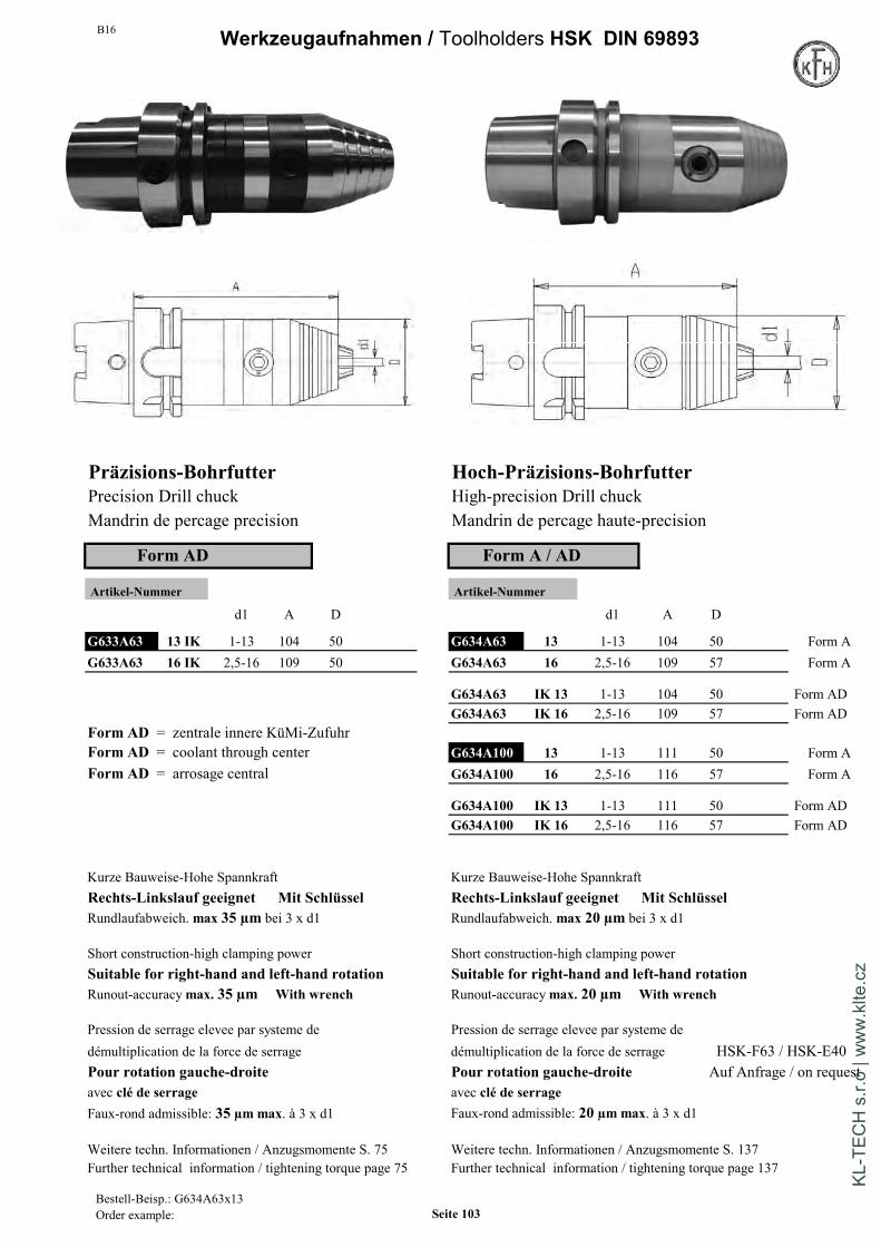
B16 Werkzeugaufnahmen / Toolholders HSK DIN 69893
Präzisions-Bohrfutter Hoch-Präzisions-BohrfutterPrecision Drill chuck High-precision Drill chuckMandrin de percage precision Mandrin de percage haute-precision
Form AD Form A / AD
Artikel-Nummer Artikel-Nummer
d1 A D d1 A D
G633A63 13 IK 1-13 104 50 G634A63 13 1-13 104 50 Form AG633A63 16 IK 2,5-16 109 50 G634A63 16 2,5-16 109 57 Form A
G634A63 IK 13 1-13 104 50 Form ADG634A63 IK 16 2,5-16 109 57 Form AD
Form AD = zentrale innere KüMi-ZufuhrForm AD = coolant through center G634A100 13 1-13 111 50 Form AForm AD = arrosage central G634A100 16 2,5-16 116 57 Form A
G634A100 IK 13 1-13 111 50 Form ADG634A100 IK 16 2,5-16 116 57 Form AD
Kurze Bauweise-Hohe Spannkraft Kurze Bauweise-Hohe SpannkraftRechts-Linkslauf geeignet Mit Schlüssel Rechts-Linkslauf geeignet Mit SchlüsselRundlaufabweich. max 35 µm bei 3 x d1 Rundlaufabweich. max 20 µm bei 3 x d1
Short construction-high clamping power Short construction-high clamping powerSuitable for right-hand and left-hand rotation Suitable for right-hand and left-hand rotationRunout-accuracymax. 35 µm With wrench Runout-accuracymax. 20 µm With wrench
Pression de serrage elevee par systeme de Pression de serrage elevee par systeme dedémultiplication de la force de serrage démultiplication de la force de serrage HSK-F63 / HSK-E40Pour rotation gauche-droite Pour rotation gauche-droite Auf Anfrage / on requestavec clé de serrage avec clé de serrageFaux-rond admissible: 35 µm max. à 3 x d1 Faux-rond admissible: 20 µm max. à 3 x d1
Weitere techn. Informationen / Anzugsmomente S. 75 Weitere techn. Informationen / Anzugsmomente S. 137Further technical information / tightening torque page 75 Further technical information / tightening torque page 137
Bestell-Beisp.: G634A63x13Order example: Seite 103
KL-T
ECH
s.r.
o | w
ww
.klte
.cz

B16Werkzeugaufnahmen / Toolholders HSK DIN 69893
Kombi-Aufsteckfräserdorn DIN 6358Combi shell mill holderPorte-fraises à double usage
Form A
Artikel-Nummer
HSK x d1 x A L l5 l1 d2
HSK G640 A40 x 16 x 50 87 17 27 32
A40 G640 A40 x 22 x 50 89 19 31 40
G640 A40 x 27 x 65 106 21 33 48
HSK G640 A50 x 16 x 50 92 17 27 32
A50 G640 A50 x 22 x 50 94 19 31 40
G640 A50 x 27 x 65 106 21 33 48
G640 A50 x 32 x 65 109 24 38 58
Zubehör / Accessories
G040 Seite/ Page 154 G042 Seite/ Page 154
G041 Seite/ Page 154
Zur Aufnahme von Fräsern mitLängs- oder Quernut
Lieferumfang: mit Fräseranzugs-schraube, Mitnehmerringund Paßfeder
Rundlaufabweichung des Kegelszur Fräseraufnahme 8 µm max
For mounting of milling cutterswith tenon drive or clutch drive
Scope of delivery:with clamping screw DIN6367,drive ring DIN 6366 and feather key
Runout of taper to journal8 µm max
Pour la fixation d'outils a rainureslongitudinales ou transversales
Avec ring de tenons, clavette et visde serrage
Faux-rond admissible du cone autourillon 8 µm max
Bestell-Beispiel: G640A463x32x 60 Seite 104
KL-T
ECH
s.r.
o | w
ww
.klte
.cz

B16 Werkzeugaufnahmen / Toolholders HSK DIN 69893
Kombi-Aufsteckfräserdorn DIN 6358Combi shell mill holderPorte-fraises à double usage
Form A
Artikel-Nummer
HSK x d1 x A L l5 l1 d2
HSK G640 A63 x 16 x 60 109 17 27 32
A63 G640 A63 x 16 x 100 149 17 27 32 auf Anfrage
G640 A63 x 16 x 160 209 17 27 32 auf Anfrage
G640 A63 x 22 x 60 111 19 31 40
G640 A63 x 22 x 100 151 19 31 40 auf Anfrage
G640 A63 x 22 x 160 211 19 31 40 auf Anfrage
G640 A63 x 27 x 60 113 21 33 48
G640 A63 x 27 x 100 153 21 33 48 auf Anfrage
G640 A63 x 27 x 160 213 21 33 48 auf Anfrage
G640 A63 x 32 x 60 116 24 38 58
G640 A63 x 32 x 100 156 24 38 58 auf Anfrage
G640 A63 x 32 x 160 216 24 38 58 auf Anfrage
G640 A63 x 40 x 70 129 27 41 70
G640 A63 x 40 x 100 159 27 41 70 auf Anfrage
G640 A63 x 40 x 160 219 27 41 70 auf Anfrage
HSK G640 A100 x 16 x 60 127 17 27 32
A100 G640 A100 x 22 x 60 129 19 31 40
G640 A100 x 27 x 60 131 21 33 48
G640 A100 x 32 x 60 134 24 38 58
G640 A100 x 40 x 70 137 27 41 70
Zur Aufnahme von Fräsern mitLängs- oder Quernut
Lieferumfang: mit Fräseranzugs-schraube, Mitnehmerringund Paßfeder
Rundlaufabweichung des Kegelszur Fräseraufnahme 8 µm max
For mounting of milling cutterswith tenon drive or clutch drive
Scope of delivery:with clamping screw DIN6367,drive ring DIN 6366 and feather key
Runout of taper to journal8 µm max
Pour la fixation d'outils a rainureslongitudinales ou transversales
Avec ring de tenons, clavette et visde serrage
Faux-rond admissible du cone autourillon 8 µm max
Bestell-Beispiel: G640A463x32x 60 Seite 105
KL-T
ECH
s.r.
o | w
ww
.klte
.cz

B16Werkzeugaufnahmen / Toolholders HSK DIN 69893
Messerkopf-Aufnahme DIN 6357Face mill holder DIN 6357Porte-fraises à tenon DIN 6357
gewuchtet / balanced / equilibréauf G6,3 bei 15.000 U/min
Form A Form ADohne innere Kühlmittelzufuhr zentrale Kühlmittelzufuhrwithout internal coolant supply coolant through center
Artikel-Nummer sans refroidissement arrosage central
HSKx d1 x A l3 d2 L
HSK G643 A40 16 x 45 17 38 65 nur in Form A
A40 G643 A40 22 x 50 19 48 70 nur in Form AG643 A40 27 x 55 21 58 75 nur in Form A
HSK G643 A50 16 x 50 17 38 70 nur in Form A
A50 G643 A50 22 x 60 21 58 80 nur in Form AG643 A50 27 x 60 24 78 85 nur in Form AG643 A50 32 x 60 24 78 85 nur in Form A
HSK G643 A63 16 x 50 K 17 38 101 nur in Form ADA63 G643 A63 16 x 100 K 17 38 149 nur in Form AD
G643 A63 16 x 160 K 17 38 209 nur in Form AD
G643 A63 22 x 50 K 19 48 101 nur in Form ADG643 A63 22 x 100 K 19 48 151 nur in Form ADG643 A63 22 x 160 K 19 48 211 nur in Form AD
G643 A63 27 x 60 K 21 58 113 nur in Form ADG643 A63 27 x 100 K 21 58 153 nur in Form ADG643 A63 27 x 160 K 21 58 213 nur in Form AD
G643 A63 32 x 60 K 24 78 116 nur in Form ADG643 A63 32 x 100 K 24 78 156 nur in Form ADG643 A63 32 x 160 K 24 78 216 nur in Form AD
G643 A63 40 x 60 K 27 88 119 * nur in Form ADG643 A63 40 x 100 K 27 88 159 * nur in Form ADG643 A63 40 x 160 K 27 88 219 * nur in Form AD
Bestell-Beispiel: G643A63 16x50KOrder example: Seite 106
KL-T
ECH
s.r.
o | w
ww
.klte
.cz
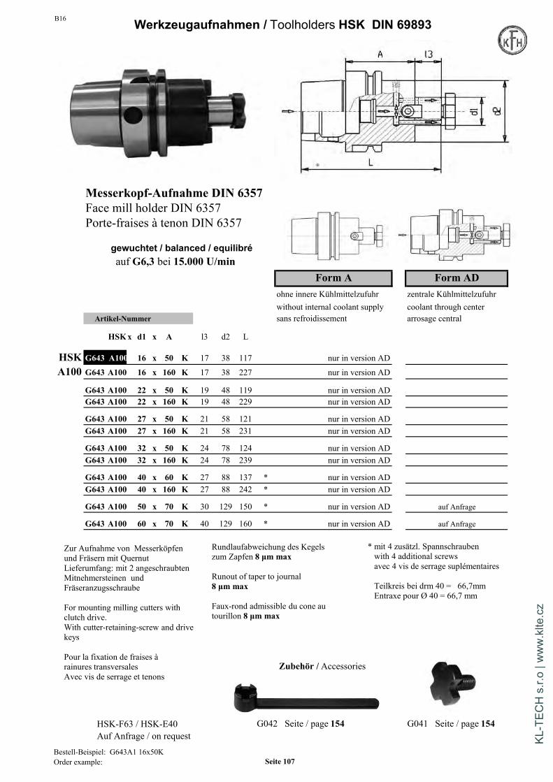
B16 Werkzeugaufnahmen / Toolholders HSK DIN 69893
Messerkopf-Aufnahme DIN 6357Face mill holder DIN 6357Porte-fraises à tenon DIN 6357
gewuchtet / balanced / equilibréauf G6,3 bei 15.000 U/min
Form A Form ADohne innere Kühlmittelzufuhr zentrale Kühlmittelzufuhrwithout internal coolant supply coolant through center
Artikel-Nummer sans refroidissement arrosage central
HSKx d1 x A l3 d2 L
HSK G643 A100 16 x 50 K 17 38 117 nur in version AD
A100 G643 A100 16 x 160 K 17 38 227 nur in version AD
G643 A100 22 x 50 K 19 48 119 nur in version ADG643 A100 22 x 160 K 19 48 229 nur in version AD
G643 A100 27 x 50 K 21 58 121 nur in version ADG643 A100 27 x 160 K 21 58 231 nur in version AD
G643 A100 32 x 50 K 24 78 124 nur in version ADG643 A100 32 x 160 K 24 78 239 nur in version AD
G643 A100 40 x 60 K 27 88 137 * nur in version ADG643 A100 40 x 160 K 27 88 242 * nur in version AD
G643 A100 50 x 70 K 30 129 150 * nur in version AD auf Anfrage
G643 A100 60 x 70 K 40 129 160 * nur in version AD auf Anfrage
Zubehör / Accessories
HSK-F63 / HSK-E40 G042 Seite / page 154 G041 Seite / page 154Auf Anfrage / on request
Zur Aufnahme von Messerköpfenund Fräsern mit QuernutLieferumfang: mit 2 angeschraubtenMitnehmersteinen undFräseranzugsschraube
For mounting milling cutters withclutch drive.With cutter-retaining-screw and drivekeys
Pour la fixation de fraises àrainures transversalesAvec vis de serrage et tenons
Rundlaufabweichung des Kegelszum Zapfen 8 µm max
Runout of taper to journal8 µm max
Faux-rond admissible du cone autourillon 8 µm max
* mit 4 zusätzl. Spannschraubenwith 4 additional screwsavec 4 vis de serrage suplémentaires
Teilkreis bei drm 40 = 66,7mmEntraxe pour Ø 40 = 66,7 mm
Bestell-Beispiel: G643A1 16x50KOrder example: Seite 107
KL-T
ECH
s.r.
o | w
ww
.klte
.cz
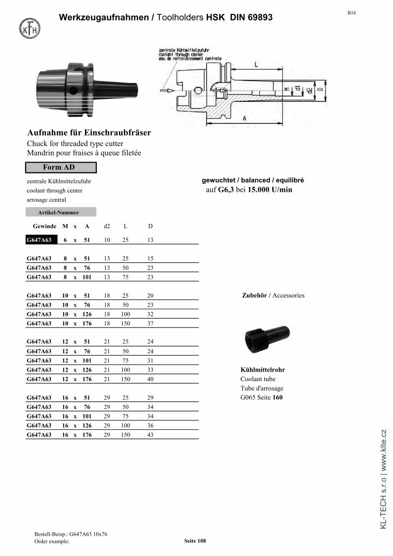
B16Werkzeugaufnahmen / Toolholders HSK DIN 69893
Aufnahme für EinschraubfräserChuck for threaded type cutterMandrin pour fraises à queue filetée
Form AD
zentrale Kühlmittelzufuhr gewuchtet / balanced / equilibrécoolant through center auf G6,3 bei 15.000 U/minarrosage central
Artikel-Nummer
Gewinde M x A d2 L D
G647A63 6 x 51 10 25 13
G647A63 8 x 51 13 25 15G647A63 8 x 76 13 50 23G647A63 8 x 101 13 75 23
G647A63 10 x 51 18 25 20 Zubehör / AccessoriesG647A63 10 x 76 18 50 23G647A63 10 x 126 18 100 32G647A63 10 x 176 18 150 37
G647A63 12 x 51 21 25 24G647A63 12 x 76 21 50 24G647A63 12 x 101 21 75 31G647A63 12 x 126 21 100 33 KühlmittelrohrG647A63 12 x 176 21 150 40 Coolant tube
Tube d'arrosageG647A63 16 x 51 29 25 29 G065 Seite 160G647A63 16 x 76 29 50 34G647A63 16 x 101 29 75 34G647A63 16 x 126 29 100 36G647A63 16 x 176 29 150 43
Bestell-Beisp.: G647A63 10x76Order example: Seite 108
KL-T
ECH
s.r.
o | w
ww
.klte
.cz

B16 Werkzeugaufnahmen / Toolholders HSK DIN 69893
Aufnahme für Einschraubfräser Mit zylindrischem SchaftChuck for threaded type cutterMandrin pour fraises à queue filetée with cylindric shaft
Form AD avec queue cylindriquezentrale Kühlmittelzufuhrcoolant through center gewuchtet / balanced / equilibréarrosage central auf G6,3 bei 15.000 U/min
Artikel-Nummer
Gewinde M x A d1 d2 L
G647A63 10 x 126 C 10,5 18 100G647A63 10 x 176 C 10,5 18 150G647A63 12 x 76 C 12,5 21 50G647A63 12 x 101 C 12,5 21 75G647A63 12 x 126 C 12,5 21 100G647A63 12 x 176 C 12,5 21 150G647A63 16 x 76 C 17 29 50G647A63 16 x 101 C 17 29 75G647A63 16 x 126 C 17 29 100G647A63 16 x 176 C 17 29 150
Zubehör / Accessories
KühlmittelrohrCoolant tubeTube d'arrosageG065 Seite 160
Bestell-Beisp.: G647A63 10x76Order example: Seite 109
KL-T
ECH
s.r.
o | w
ww
.klte
.cz

B16Werkzeugaufnahmen / Toolholders HSK DIN 69893
Aufnahme für EinschraubfräserChuck for threaded type cutterMandrin pour fraises à queue filetée
Form AD
zentrale Kühlmittelzufuhr gewuchtet / balanced / equilibrécoolant through center auf G6,3 bei 15.000 U/minarrosage central
Artikel-Nummer
M x A d1 d2 L D
G647A100 8 x 79 8,5 13 50 23G647A100 10 x 79 10,5 18 50 23G647A100 12 x 79 12,5 21 50 24G647A100 12 x 129 12,5 21 100 33G647A100 12 x 179 12,5 21 150 40G647A100 16 x 79 17 29 50 34G647A100 16 x 129 17 29 100 36 Zubehör / AccessoriesG647A100 16 x 179 17 29 150 42,5
KühlmittelrohrCoolant tubeTube d'arrosageG065 Seite 160
Bestell-Beisp.: G647A63 10x76Order example: Seite 110
KL-T
ECH
s.r.
o | w
ww
.klte
.cz

B16 Werkzeugaufnahmen / Toolholders HSK DIN 69893
Kurze Einsatzhülsen f. MK m. Lappen DIN 6383Morse taper adaptor for flat tangDouilles intermédiares a cone morse
Form AD
Artikel-Nummer gewuchtet / balanced / equilibréMK x A D L auf G6,3 bei 20.000 U/min
G660A63 1 x 100 25 132G660A63 2 x 120 32 152 Rundlaufabweichung max 10µmG660A63 3 x 140 40 172 Max runout: 10µmG660A63 4 x 160 48 192 Faux-rond admissible: 10µm max.
G660A100 2 x 120 32 170G660A100 3 x 150 40 200G660A100 4 x 170 48 220
Kurze Fräserhülsen f. MK m.GewindeDIN 6364Morse taper adaptor with draw threadDouilles intermédiares a cone morse avec filetage
Form A
Artikel-Nummer gewuchtet / balanced / equilibréMK x A D L auf G6,3 bei 20.000 U/min
G661A63 1 x 100 25 132G661A63 2 x 120 32 152 Rundlaufabweichung max 10µmG661A63 3 x 140 40 172 Max runout: 10µmG661A63 4 x 160 48 192 Faux-rond admissible: 10µm max.
G661A100 2 x 120 32 170G661A100 3 x 150 40 200G661A100 4 x 170 48 220
Bestell-Beisp.: G660 A63x1Order example: Seite 111
KL-T
ECH
s.r.
o | w
ww
.klte
.cz
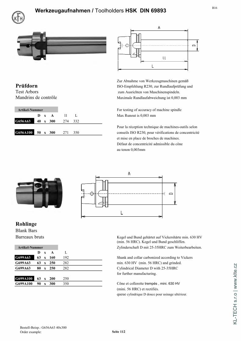
B16Werkzeugaufnahmen / Toolholders HSK DIN 69893
Zur Abnahme von Werkzeugmaschinen gemäßPrüfdorn ISO-Empfehlung R230, zur Rundlaufprüfung undTest Arbors zum Ausrichten von Maschinenspindeln.Mandrins de contrôle Maximale Rundlaufabweichung ist 0,003 mm
Artikel-Nummer For testing of accuracy of machine spindleD x A l1 L Max Runout is 0,003 mm
G656A63 40 x 300 274 332Pour la réception technique de machines-outils selon
G656A100 50 x 300 271 350 conseils ISO R230, pour vérifications de concentricitéet mise en place de broches de machines.Défaut de concentricité admissible du côneau tenon 0,003mm
RohlingeBlank BarsBarreaux bruts Kegel und Bund gehärtet auf Vickershärte min. 630 HV
(min. 56 HRC). Kegel und Bund geschliffen.Artikel-Nummer Zylinderschaft D mit 25-35HRC zum Weiterbearbeiten.
D x A LG699A63 63 x 160 192 Shank and collar carbonized according to VickersG699A63 63 x 250 282 min. 630 HV (min. 56 HRC) and grinded.G699A63 80 x 250 282 Cylindrical Diameter D with 25-35HRC
for further manufacturing.G699A100 63 x 200 250G699A100 90 x 300 350 Cône et collerette trempés , mini. 630 HV
(mini. 56 HRC) et rectifiés.queue cylindrique D douce pour usinage ultérieur.
Bestell-Beisp.: G656A63 40x300Order example: Seite 112
KL-T
ECH
s.r.
o | w
ww
.klte
.cz
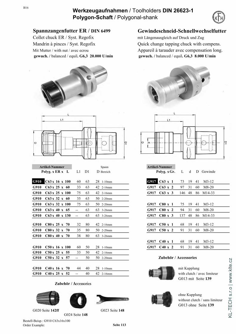
B16 Werkzeugaufnahmen / Toolholders DIN 26623-1Polygon-Schaft / Polygonal-shank
Spannzangenfutter ER / DIN 6499 Gewindeschneid-SchnellwechselfutterCollet chuck ER / Syst. Regofix mit Längenausgleich auf Druck und ZugMandrin à pinces / Syst. Regofix Quick change tapping chuck with compens.Mit Mutter / with nut / avec ecrou Appareil à tarauder avec compensation long.gewuch. / balanced / equil. G6,3 20.000 U/min gewuch. / balanced / equil. G6,3 8.000 U/min
Artikel-Nummer Spann Artikel-NummerPolyg. x ER x L L1 D1 D Bereich Polyg. xGr. L d D Gewinde
G910 C63 x 16 x 100 60 63 28 1-10mm G917 C63 x 1 73 19 41 M3-12G910 C63 x 25 x 60 33 63 42 2-16mm G917 C63 x 2 97 31 60 M8-20G910 C63 x 25 x 100 75 63 42 2-16mm G917 C63 x 3 146 48 86 M14-33G910 C63 x 32 x 60 35 63 50 2-20mm
G910 C63 x 32 x 100 75 63 50 2-20mm G917 C80 x 1 75 19 41 M3-12G910 C63 x 40 x 65 -- 63 63 3-26mm G917 C80 x 2 94 31 60 M8-20G910 C63 x 40 x 130 -- 63 63 3-26mm G917 C80 x 3 137 48 86 M14-33
G910 C80 x 25 x 70 32 80 42 2-16mm G917 C50 x 1 68 19 41 M3-12G910 C80 x 32 x 70 35 80 50 2-20mm G917 C50 x 2 91 31 60 M8-20G910 C80 x 40 x 70 38 80 63 3-26mm
G917 C40 x 1 68 19 41 M3-12G910 C50 x 16 x 100 60 50 28 1-10mm G917 C40 x 2 91 31 60 M8-20G910 C50 x 25 x 55 33 50 42 2-16mm
G910 C50 x 32 x 57 -- 50 50 2-20mm Zubehör / Accessories
G910 C40 x 16 x 70 44 40 28 1-10mm mit KupplungG910 C40 x 25 x 52 -- 40 42 2-16mm with clutch / avec limiteur
G013 mit Seite 139Zubehör / Accessories
ohne Kupplungwithout clutch / sans limiteurG013 ohne Seite 139
G020 Seite 142ff G023 Seite 148G024 Seite 148
Bestell-Beisp.: G910 C63x16x100Order Example: Seite 113
KL-T
ECH
s.r.
o | w
ww
.klte
.cz

B16Werkzeugaufnahmen / Toolholders DIN 26623-1Polygon-Schaft / Polygonal-shank
Spannfutter WeldonEndmill-holder Weldon /DIN1835BPorte-fraises Weldon /DIN1835B
gewuchtet / balanced / equilibréauf G6,3 bei 20.000 U/min
Artikel-Nummer Artikel-NummerPolyg. x d x L L1 D1 D Polyg. x d x L L1 D1 D
G920 C63 x 6 x 55 25 63 25 G920 C40 x 6 x 50 25 40 25G920 C63 x 8 x 55 26 63 28 G920 C40 x 8 x 50 26 40 28G920 C63 x 10 x 60 30 63 35 G920 C40 x 10 x 51 29 40 35G920 C63 x 12 x 60 33 63 42 G920 C40 x 12 x 55 -- 40 42G920 C63 x 14 x 60 34 63 44 G920 C40 x 16 x 55 -- 40 48G920 C63 x 16 x 65 34 63 48G920 C63 x 20 x 65 38 63 52 G920 C50 x 6 x 50 26 50 25G920 C63 x 25 x 80 -- 63 63 G920 C50 x 8 x 50 26 50 28G920 C63 x 32 x 90 -- 63 72 G920 C50 x 10 x 55 28 50 35
G920 C50 x 12 x 60 36 50 42G920 C80 x 6 x 70 27 80 25 G920 C50 x 16 x 60 40 50 48G920 C80 x 8 x 70 28 80 28 G920 C50 x 20 x 60 -- 50 52G920 C80 x 10 x 70 29 80 35 G920 C50 x 25 x 80 -- 50 64G920 C80 x 12 x 70 31 80 42G920 C80 x 16 x 70 32 80 48 Zubehör / AccessoriesG920 C80 x 20 x 70 35 80 52G920 C80 x 25 x 80 50 80 64G920 C80 x 32 x 80 50 80 72G920 C80 x 40 x 110 -- 80 80
Reduzierung / reducerG010 Seite 133
Drehmoment-Tabelle Seite 147recommended tightening torque page 147 Ersatzschraubetableau de couples recommandes page 147 Spare screw
G010B Seite 133
Bestell-Beisp.: G920 C63x 6x 55Order Example: Seite 114
KL-T
ECH
s.r.
o | w
ww
.klte
.cz

B16 Werkzeugaufnahmen / Toolholders DIN 26623-1Polygon-Schaft / Polygonal-shank
Bohrstangenhalter Messerkopf-Aufnahme DIN 6357Adaptor for drills Face mill holder DIN 6357Porte-outil pour foret a plaquettes Porte-fraises à tenon DIN 6357
gewuch. / balanced / equil. G6,3 8.000 U/min gewuch. / balanced / equil. G6,3 15.000 U/min
Artikel-Nummer Artikel-NummerPolyg. x d x L L1 D1 D Polyg. x d x L L1 D1 D
G922 C63 x 16 x 70 41 63 36 G942 C63 x 16 x 40 11 63 32G922 C63 x 20 x 70 42 63 40 G942 C63 x 22 x 25 16 63 55G922 C63 x 25 x 72 48 63 45 G942 C63 x 27 x 25 18 63 63G922 C63 x 32 x 75 50 63 52 G942 C63 x 32 x 25 20 63 63
G942 C80 x 16 x 50 11 80 32G942 C80 x 22 x 30 16 80 55G942 C80 x 27 x 30 18 80 65G942 C80 x 32 x 30 20 80 80G942 C80 x 40 x 30 23 80 80
G942 C40 x 16 x 32 11 40 32G942 C40 x 22 x 25 16 40 40
G942 C50 x 16 x 35 11 50 32G942 C50 x 22 x 25 16 50 50G942 C50 x 27 x 25 18 50 56G942 C50 x 32 x 40 20 50 63
Zubehör / Accessories
G041 Seite / page 154 G042 Seite / page 154
Bestell-Beisp.: G922 C63x16x70Order Example: Seite 115
KL-T
ECH
s.r.
o | w
ww
.klte
.cz

B16Werkzeugaufnahmen / Toolholders DIN 26623-1Polygon-Schaft / Polygonal-shank
Reduzierung SK/DIN69871-Polygon Reduzierung MAS403 BT-PolygonReduction SK-DIN69871 on polygonal shank Reduction MAS BT on polygonal shankReduction SK-DIN69871-attachm. polygonal Reduction MAS BT-attachm. polygonal
Artikel-Nummer Artikel-NummerSK Polyg. L D1 Form BT Polyg. L D1 Form
G362 50 x C63 x 50 63 AD/B G462 50 x C63 x 50 63 AD/BG362 50 x C63 x 80 63 AD/B G462 50 x C63 x 90 63 AD/B
G362 50 x C80 x 70 80 AD/B G462 50 x C80 x 70 80 AD/B
G362 50 x C50 x 30 50 AD/B G462 50 x C50 x 40 50 AD/BG362 50 x C50 x 110 50 AD/B
G462 40 x C40 x 30 40 AD/BG362 40 x C40 x 30 40 AD/B G462 50 x C40 x 70 40 AD/BG362 50 x C40 x 30 40 AD/B
Bestell-Beisp.: G362 50xC63x 50Order Example: Seite 116
KL-T
ECH
s.r.
o | w
ww
.klte
.cz

B16 Werkzeugaufnahmen / Toolholders DIN 26623-1Polygon-Schaft / Polygonal-shank
Verlängerung Polygon auf Polygon Reduzierung Polygon auf PolygonExtension polygonal on polygonal shank Reduction polygonal on polygonal shankAllonge polygonal - attachm. polygonal Reduction polygonal -attachm. polygonal
Artikel-Nummer Artikel-NummerAussen Innen L D1 Aussen Innen L D1 D
G964 C63 - C63 x 100 63 G962 C63 - C40 x 80 63 40G964 C63 - C63 x 140 63 G962 C63 - C50 x 80 63 50
G964 C80 - C80 x 100 80 G962 C80 - C50 x 120 63 50G964 C80 - C80 x 125 80 G962 C80 - C63 x 80 63 63
G964 C50 - C50 x 50 50 G962 C50 - C40 x 65 50 40G964 C50 - C50 x 80 50
G964 C40 - C40 x 60 40G964 C40 - C40 x 80 40
Bestell-Beisp.: G964 C63-C63x100Order Example: Seite 117
KL-T
ECH
s.r.
o | w
ww
.klte
.cz
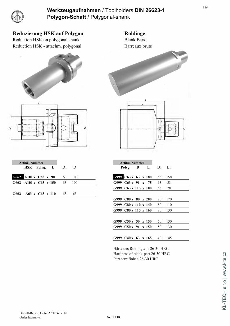
B16Werkzeugaufnahmen / Toolholders DIN 26623-1Polygon-Schaft / Polygonal-shank
Reduzierung HSK auf Polygon RohlingeReduction HSK on polygonal shank Blank BarsReduction HSK - attachm. polygonal Barreaux bruts
Artikel-Nummer Artikel-NummerHSK Polyg. L D1 D Polyg. D L D1 L1
G662 A100 x C63 x 90 63 100 G999 C63 x 63 x 180 63 158G662 A100 x C63 x 150 63 100 G999 C63 x 91 x 75 63 53
G999 C63 x 115 x 100 63 78G662 A63 x C63 x 110 63 63
G999 C80 x 80 x 200 80 170G999 C80 x 110 x 140 80 110G999 C80 x 115 x 160 80 130
G999 C50 x 50 x 150 50 130G999 C50 x 91 x 150 50 130
G999 C40 x 63 x 165 40 145
Härte des Rohlingteils 26-30 HRCHardness of blank-part 26-30 HRCPart semifinie a 26-30 HRC
Bestell-Beisp.: G662 A63xc63x110Order Example: Seite 118
KL-T
ECH
s.r.
o | w
ww
.klte
.cz
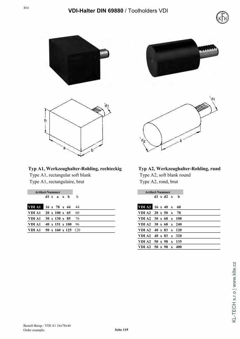
B16 VDI-Halter DIN 69880 / Toolholders VDI
Typ A1, Werkzeughalter-Rohling, rechteckig Typ A2, Werkzeughalter-Rohling, rundType A1, rectangular soft blank Type A2, soft blank roundType A1, rectangulaire, brut Type A2, rond, brut
Artikel-Nummer Artikel-Nummerd1 x a x b h d1 x d2 x b
VDI A1 16 x 78 x 44 44 VDI A2 16 x 40 x 60VDI A1 20 x 100 x 65 60 VDI A2 20 x 50 x 70VDI A1 30 x 130 x 85 76 VDI A2 30 x 68 x 100VDI A1 40 x 151 x 100 96 VDI A2 30 x 68 x 240VDI A1 50 x 160 x 125 120 VDI A2 40 x 83 x 120
VDI A2 40 x 83 x 320VDI A2 50 x 98 x 135VDI A2 50 x 98 x 400
Bestell-Beisp.: VDI A1 16x78x44Order example: Seite 119
KL-T
ECH
s.r.
o | w
ww
.klte
.cz
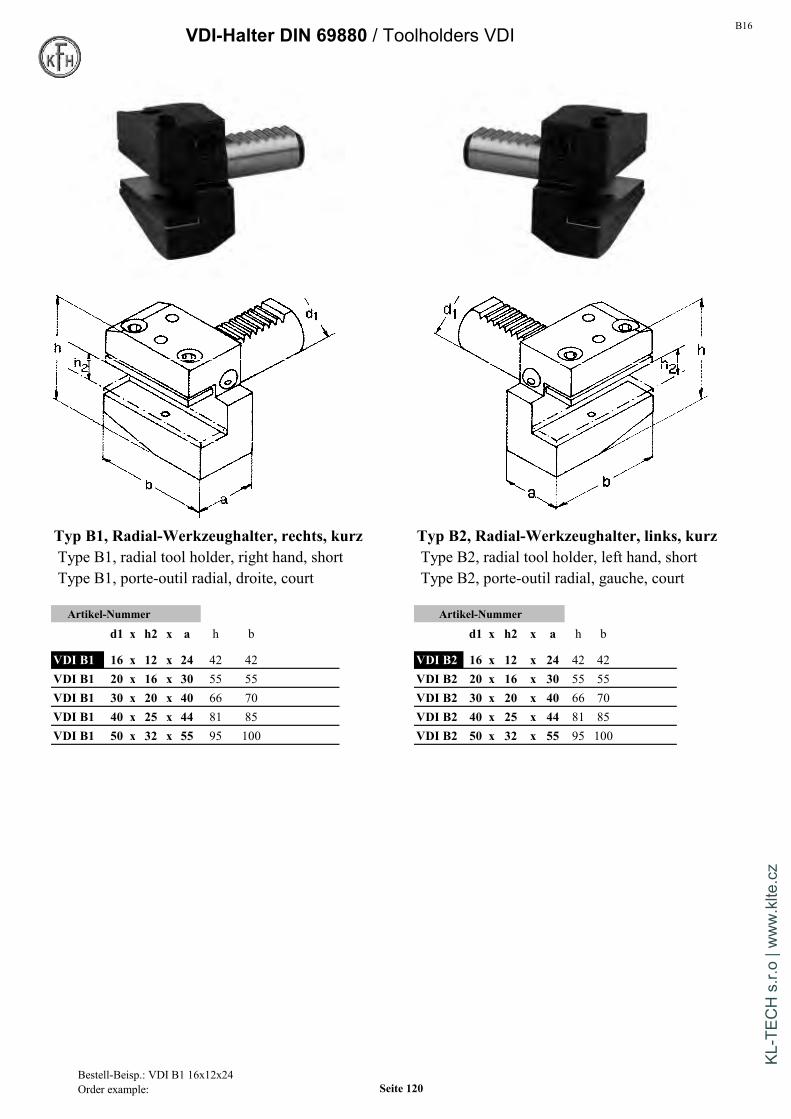
B16VDI-Halter DIN 69880 / Toolholders VDI
Typ B1, Radial-Werkzeughalter, rechts, kurz Typ B2, Radial-Werkzeughalter, links, kurzType B1, radial tool holder, right hand, short Type B2, radial tool holder, left hand, shortType B1, porte-outil radial, droite, court Type B2, porte-outil radial, gauche, court
Artikel-Nummer Artikel-Nummer
d1 x h2 x a h b d1 x h2 x a h b
VDI B1 16 x 12 x 24 42 42 VDI B2 16 x 12 x 24 42 42VDI B1 20 x 16 x 30 55 55 VDI B2 20 x 16 x 30 55 55VDI B1 30 x 20 x 40 66 70 VDI B2 30 x 20 x 40 66 70VDI B1 40 x 25 x 44 81 85 VDI B2 40 x 25 x 44 81 85VDI B1 50 x 32 x 55 95 100 VDI B2 50 x 32 x 55 95 100
Bestell-Beisp.: VDI B1 16x12x24Order example: Seite 120
KL-T
ECH
s.r.
o | w
ww
.klte
.cz
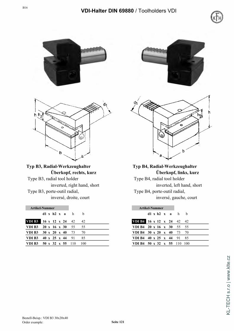
B16VDI-Halter DIN 69880 / Toolholders VDI
Typ B3, Radial-Werkzeughalter Typ B4, Radial-WerkzeughalterÜberkopf, rechts, kurz Überkopf, links, kurz
Type B3, radial tool holder Type B4, radial tool holderinverted, right hand, short inverted, left hand, short
Type B3, porte-outil radial, Type B4, porte-outil radial,inversé, droite, court inversé, gauche, court
Artikel-Nummer Artikel-Nummer
d1 x h2 x a h b d1 x h2 x a h b
VDI B3 16 x 12 x 24 42 42 VDI B4 16 x 12 x 24 42 42VDI B3 20 x 16 x 30 55 55 VDI B4 20 x 16 x 30 55 55VDI B3 30 x 20 x 40 73 70 VDI B4 30 x 20 x 40 73 70VDI B3 40 x 25 x 44 91 85 VDI B4 40 x 25 x 44 91 85VDI B3 50 x 32 x 55 110 100 VDI B4 50 x 32 x 55 110 100
Bestell-Beisp.: VDI B3 30x20x40Order example: Seite 121
KL-T
ECH
s.r.
o | w
ww
.klte
.cz

B16VDI-Halter DIN 69880 / Toolholders VDI
Typ B5, Radial-Werkzeughalter, rechts, lang Typ B6, Radial-Werkzeughalter, links, langType B5, radial tool holder, right hand, long Type B6, radial tool holder, left hand, longType B5, porte-outil radial, droite, long Type B6, porte-outil radial, gauche, long
Artikel-Nummer Artikel-Nummer
d1 x h2 x a h b d1 x h2 x a h b
VDI B5 16 x 12 x 24 42 58 VDI B6 16 x 12 x 24 42 58VDI B5 20 x 16 x 30 55 75 VDI B6 20 x 16 x 30 55 75VDI B5 30 x 20 x 40 66 100 VDI B6 30 x 20 x 40 66 100VDI B5 40 x 25 x 44 91 118 VDI B6 40 x 25 x 44 91 118VDI B5 50 x 32 x 55 95 130 VDI B6 50 x 32 x 55 95 130
Bestell-Beisp.: VDI B5 30x20x40Order example: Seite 122
KL-T
ECH
s.r.
o | w
ww
.klte
.cz

B16VDI-Halter DIN 69880 / Toolholders VDI
Typ B7, Radial-Werkzeughalter Typ B8, Radial-WerkzeughalterÜberkopf, rechts, lang Überkopf, links, lang
Type B7, radial tool holder Type B8, radial tool holderinverted, right hand, long inverted, left hand, long
Type B7, porte-outil radial, Type B8, porte-outil radial,inversé, droite, long inversé, gauche, long
Artikel-Nummer Artikel-Nummer
d1 x h2 x a h b d1 x h2 x a h b
VDI B7 16 x 12 x 24 42 58 VDI B8 16 x 12 x 24 42 58VDI B7 20 x 16 x 30 55 75 VDI B8 20 x 16 x 30 55 75VDI B7 30 x 20 x 40 73 100 VDI B8 30 x 20 x 40 73 100VDI B7 40 x 25 x 44 91 118 VDI B8 40 x 25 x 44 91 118VDI B7 50 x 32 x 55 110 130 VDI B8 50 x 32 x 55 110 130
Bestell-Beisp.: VDI B7 30x20x40 Seite 123
KL-T
ECH
s.r.
o | w
ww
.klte
.cz

B16VDI-Halter DIN 69880 / Toolholders VDI
Typ C1, Axial-Werkzeughalter, rechts Typ C2, Axial-Werkzeughalter, linksType C1, axial tool holder, right hand Type C2, axial tool holder, left handType C1, port-outil axial, droite Type C2, port-outil axial, gauche
Artikel-Nummer Artikel-Nummer
d1 x h2 x b h a d1 x h2 x b h a
VDI C1 16 x 12 x 44 42 43 VDI C2 16 x 12 x 44 42 43VDI C1 20 x 16 x 50 55 52 VDI C2 20 x 16 x 50 55 52VDI C1 30 x 20 x 70 66 70 VDI C2 30 x 20 x 70 66 70VDI C1 40 x 25 x 85 91 85 VDI C2 40 x 25 x 85 91 85VDI C1 50 x 32 x 100 95 100 VDI C2 50 x 32 x 100 95 100
Bestell-Beisp.: VDI CI 40x25x85Order example: Seite 124
KL-T
ECH
s.r.
o | w
ww
.klte
.cz

B16VDI-Halter DIN 69880 / Toolholders VDI
Typ C3, Axial-Werkzeughalter Typ C4, Axial-WerkzeughalterÜberkopf, rechts Überkopf, links
Type C3, axial tool holder Type C4, axial tool holderinverted, right hand inverted, left hand
Type C3, porte-outil axial Type C4, porte-outil axialinversé, droite inversé, gauche
Artikel-Nummer Artikel-Nummer
d1 x h2 x b h a d1 x h2 x b h a
VDI C3 16 x 12 x 44 42 43 VDI C4 16 x 12 x 44 42 43VDI C3 20 x 16 x 50 55 52 VDI C4 20 x 16 x 50 55 52VDI C3 30 x 20 x 70 73 70 VDI C4 30 x 20 x 70 73 70VDI C3 40 x 25 x 85 91 85 VDI C4 40 x 25 x 85 91 85VDI C3 50 x 32 x 100 110 100 VDI C4 50 x 32 x 100 110 100
Bestell-Beisp.: VDI C3 30x20x70Order example: Seite 125
KL-T
ECH
s.r.
o | w
ww
.klte
.cz
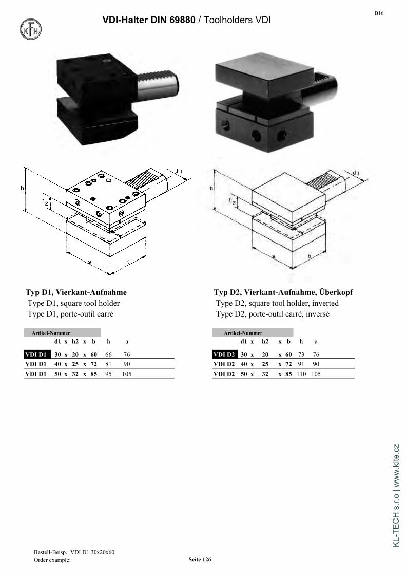
B16VDI-Halter DIN 69880 / Toolholders VDI
Typ D1, Vierkant-Aufnahme Typ D2, Vierkant-Aufnahme, ÜberkopfType D1, square tool holder Type D2, square tool holder, invertedType D1, porte-outil carré Type D2, porte-outil carré, inversé
Artikel-Nummer Artikel-Nummerd1 x h2 x b h a d1 x h2 x b h a
VDI D1 30 x 20 x 60 66 76 VDI D2 30 x 20 x 60 73 76VDI D1 40 x 25 x 72 81 90 VDI D2 40 x 25 x 72 91 90VDI D1 50 x 32 x 85 95 105 VDI D2 50 x 32 x 85 110 105
Bestell-Beisp.: VDI D1 30x20x60Order example: Seite 126
KL-T
ECH
s.r.
o | w
ww
.klte
.cz
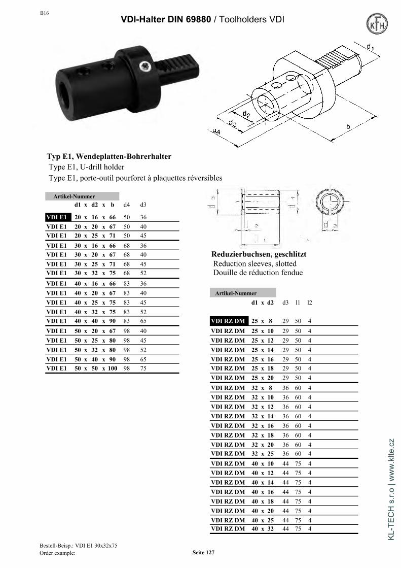
B16VDI-Halter DIN 69880 / Toolholders VDI
Typ E1, Wendeplatten-BohrerhalterType E1, U-drill holderType E1, porte-outil pourforet à plaquettes réversibles
Artikel-Nummerd1 x d2 x b d4 d3
VDI E1 20 x 16 x 66 50 36VDI E1 20 x 20 x 67 50 40VDI E1 20 x 25 x 71 50 45VDI E1 30 x 16 x 66 68 36VDI E1 30 x 20 x 67 68 40 Reduzierbuchsen, geschlitztVDI E1 30 x 25 x 71 68 45 Reduction sleeves, slottedVDI E1 30 x 32 x 75 68 52 Douille de réduction fendueVDI E1 40 x 16 x 66 83 36VDI E1 40 x 20 x 67 83 40 Artikel-NummerVDI E1 40 x 25 x 75 83 45 d1 x d2 d3 l1 l2VDI E1 40 x 32 x 75 83 52VDI E1 40 x 40 x 90 83 65 VDI RZ DM 25 x 8 29 50 4VDI E1 50 x 20 x 67 98 40 VDI RZ DM 25 x 10 29 50 4VDI E1 50 x 25 x 80 98 45 VDI RZ DM 25 x 12 29 50 4VDI E1 50 x 32 x 80 98 52 VDI RZ DM 25 x 14 29 50 4VDI E1 50 x 40 x 90 98 65 VDI RZ DM 25 x 16 29 50 4VDI E1 50 x 50 x 100 98 75 VDI RZ DM 25 x 18 29 50 4
VDI RZ DM 25 x 20 29 50 4VDI RZ DM 32 x 8 36 60 4VDI RZ DM 32 x 10 36 60 4VDI RZ DM 32 x 12 36 60 4VDI RZ DM 32 x 14 36 60 4VDI RZ DM 32 x 16 36 60 4VDI RZ DM 32 x 18 36 60 4VDI RZ DM 32 x 20 36 60 4VDI RZ DM 32 x 25 36 60 4VDI RZ DM 40 x 10 44 75 4VDI RZ DM 40 x 12 44 75 4VDI RZ DM 40 x 14 44 75 4VDI RZ DM 40 x 16 44 75 4VDI RZ DM 40 x 18 44 75 4VDI RZ DM 40 x 20 44 75 4VDI RZ DM 40 x 25 44 75 4VDI RZ DM 40 x 32 44 75 4
Bestell-Beisp.: VDI E1 30x32x75Order example: Seite 127
KL-T
ECH
s.r.
o | w
ww
.klte
.cz
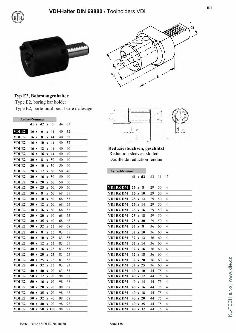
B16VDI-Halter DIN 69880 / Toolholders VDI
Typ E2, BohrstangenhalterType E2, boring bar holderType E2, porte-outil pour barre d'alésage
Artikel-Nummerd1 x d2 x b d4 d3
VDI E2 16 x 6 x 44 40 32VDI E2 16 x 8 x 44 40 32VDI E2 16 x 10 x 44 40 32VDI E2 16 x 12 x 44 40 40 Reduzierbuchsen, geschlitztVDI E2 16 x 16 x 44 40 40 Reduction sleeves, slottedVDI E2 20 x 8 x 50 50 40 Douille de réduction fendueVDI E2 20 x 10 x 50 50 40VDI E2 20 x 12 x 50 50 40 Artikel-NummerVDI E2 20 x 16 x 50 50 40 d1 x d2 d3 l1 l2VDI E2 20 x 20 x 50 50 50VDI E2 20 x 25 x 60 50 50 VDI RZ DM 25 x 8 29 50 4VDI E2 30 x 8 x 60 68 55 VDI RZ DM 25 x 10 29 50 4VDI E2 30 x 10 x 60 68 55 VDI RZ DM 25 x 12 29 50 4VDI E2 30 x 12 x 60 68 55 VDI RZ DM 25 x 14 29 50 4VDI E2 30 x 16 x 60 68 55 VDI RZ DM 25 x 16 29 50 4VDI E2 30 x 20 x 60 68 55 VDI RZ DM 25 x 18 29 50 4VDI E2 30 x 25 x 60 68 68 VDI RZ DM 25 x 20 29 50 4VDI E2 30 x 32 x 75 68 68 VDI RZ DM 32 x 8 36 60 4VDI E2 40 x 8 x 75 83 55 VDI RZ DM 32 x 10 36 60 4VDI E2 40 x 10 x 75 83 55 VDI RZ DM 32 x 12 36 60 4VDI E2 40 x 12 x 75 83 55 VDI RZ DM 32 x 14 36 60 4VDI E2 40 x 16 x 75 83 55 VDI RZ DM 32 x 16 36 60 4VDI E2 40 x 20 x 75 83 55 VDI RZ DM 32 x 18 36 60 4VDI E2 40 x 25 x 75 83 55 VDI RZ DM 32 x 20 36 60 4VDI E2 40 x 32 x 75 83 83 VDI RZ DM 32 x 25 36 60 4VDI E2 40 x 40 x 90 83 83 VDI RZ DM 40 x 10 44 75 4VDI E2 50 x 12 x 90 98 68 VDI RZ DM 40 x 12 44 75 4VDI E2 50 x 16 x 90 98 68 VDI RZ DM 40 x 14 44 75 4VDI E2 50 x 20 x 90 98 68 VDI RZ DM 40 x 16 44 75 4VDI E2 50 x 25 x 90 98 68 VDI RZ DM 40 x 18 44 75 4VDI E2 50 x 32 x 90 98 68 VDI RZ DM 40 x 20 44 75 4VDI E2 50 x 40 x 90 98 98 VDI RZ DM 40 x 25 44 75 4VDI E2 50 x 50 x 100 98 98 VDI RZ DM 40 x 32 44 75 4
Bestell-Beisp.: VDI E2 20x10x50 Seite 128
KL-T
ECH
s.r.
o | w
ww
.klte
.cz

B16VDI-Halter DIN 69880 / Toolholders VDI
Typ E3, Spannzangenfutter OZ / System OrtliebType E3, collet chucks OZ / Syst. OrtliebType E3, mandrin à pinces OZ / Syst. Ortlieb
Artikel-Nummerd x OZ x l D S.Ber.
VDI E3 16 x 415E x 65 40 2-16VDI E3 20 x 415E x 57 50 2-16VDI E3 30 x 462E x 75 68 2-25VDI E3 40 x 462E x 75 83 2-25VDI E3 40 x 467E x 90 83 4-32VDI E3 50 x 462E x 75 98 2-25VDI E3 50 x 467E x 90 98 4-32
Zubehör / Accessories
G016 Seite 140
G017 Seite 141
G018 Seite 141
OZ-Spannbereiche:OZ-Clamping-Range:OZ-Plage de serrage:
OZ16 = 415E = 2 - 16 mmOZ25 = 462E = 2 - 25 mmOZ32 = 467E = 4 - 32 mm
LieferumfangIncluding / livraison:mit Spannmutter DIN6388Dwith Collet-Nut DIN6388Davec écrou de serrage DIN6388D
Bestell-Beisp.: VDI E3 30x462Ex75 Seite 129
KL-T
ECH
s.r.
o | w
ww
.klte
.cz

B16VDI-Halter DIN 69880 / Toolholders VDI
Typ E4, Spannzangenfutter ER für Spannzangen DIN 6499Type E4, collet chuck ER / Syst. Regofix for collets DIN 6499Type E4, mandrin à pinces / Syst. Regofix pour pinces DIN 6499
Artikel-Nummerd1 x ER b d3 S.Ber. d4
VDI E4 16 x 16 40 40 1-10 32VDI E4 16 x 20 44 40 1-13 35VDI E4 20 x 16 40 50 1-10 32VDI E4 20 x 25 54 50 2-16 42VDI E4 30 x 25 57 68 2-16 42VDI E4 30 x 32 62 68 2-20 50VDI E4 30 x 40 70 68 3-30 63VDI E4 40 x 25 70 83 2-16 42VDI E4 40 x 32 62 83 2-20 50VDI E4 40 x 40 75 83 3-30 63VDI E4 50 x 32 84 98 2-20 50VDI E4 50 x 40 75 98 3-30 63
Zubehör / Accessories
G020 Seite 142ff G023 Seite 148
Drehmoment-Tabelle Seite 147recommended tightening torque page 147tableau de couples recommandes page 147
G024 Seite 148
ER-Spannbereiche:ER-Clamping-Range:ER-Plage de serrage
ER16 = 1 - 10 mmER20 = 1 - 13 mmER25 = 2 - 16 mmER32 = 2 - 20 mmER40 = 3 - 30 mm
LieferumfangIncluding / livraison:mit Spannmutter DIN6388Dwith Collet-Nut DIN6388Davec écrou de serrage DIN6388D
Bestell-Beisp.: VDI E4 20xER16x40Order example: Seite 130
KL-T
ECH
s.r.
o | w
ww
.klte
.cz

B16VDI-Halter DIN 69880 / Toolholders VDI
Skizze zeigt Version ZE (Kühlmittel zentral)Drawing shows version ZE ( central coolant)
Typ F, Morsekegelaufnahme Bohrfutter VDIType F, Morse taper holder Drill Chuck VDIType F, Porte-outil pour cone morse Mandrin de perçage VDI
Artikel-Nummer Artikel-Nummerd1 x MK x b h d2 d4 b1 d x d1 D L L1
VDI F 20 x 1 x 22 23 50 50 22 VDI Bo 30 x 1-13 IK 50 90 96VDI F 20 x 2 x 90 23 50 40 30 VDI Bo 30 x 1-13 ZE 50 90 96VDI F 30 x 1 x 27 28 68 68 27 VDI Bo 30 x 3-16 IK 57 95 101VDI F 30 x 2 x 27 28 68 55 36 VDI Bo 30 x 3-16 ZE 57 95 101VDI F 30 x 3 x 73 28 68 58 22 VDI Bo 40 x 1-13 IK 50 90 96VDI F 40 x 1 x 36 33 83 55 22 VDI Bo 40 x 1-13 ZE 50 90 96VDI F 40 x 2 x 36 33 83 55 22 VDI Bo 40 x 3-16 IK 57 95 101VDI F 40 x 3 x 50 33 83 58 22 VDI Bo 40 x 3-16 ZE 57 95 101VDI F 40 x 4 x 80 33 83 68 22 VDI Bo 50 x 1-13 IK 50 90 96VDI F 50 x 2 x 36 35 98 55 30 VDI Bo 50 x 1-13 ZE 50 90 96VDI F 50 x 3 x 36 35 98 58 30 VDI Bo 50 x 3-16 IK 57 95 101VDI F 50 x 4 x 50 35 98 68 30 VDI Bo 50 x 3-16 ZE 57 95 101VDI F 50 x 5 x 68 35 98 75 30
Mit Schlüssel / with wrench / avec clé de serrage
Version ZE = Kühlmittel zentralVersion ZE = central coolantVersion ZE = arrosage central
Version IK = Kühlmittel über KugeldüseVersion IK = coolant via coolant noozleVersion IK = arrosage par boule ajutage
Bestell-Beisp.: VDI F 40x3x50Order example: Seite 131
KL-T
ECH
s.r.
o | w
ww
.klte
.cz

B16VDI-Halter DIN 69880 / Toolholders VDI
StangengreiferBar pullerTire-barres
Artikel-Nummer Spannber. 1 Spannber. 2d1 x l1 x b1 h1 l3 l2 range 1 range 2
d2 d2VDI Stang 20 x 46 x 50 72 34 4 6-45mm 45-100mmVDI Stang 30 x 46 x 50 72 34 4 6-45mm 45-100mmVDI Stang 40 x 48 x 60 110 34 4 6-56mm 56-110mmVDI Stang 50 x 67 x 65 130 34 5 6-56mm 56-110mm
Verwendung: Für Stangenvorschub an Maschinen ohne Stangen-Lademagazin. Maß l2 entspricht der minimal erforderlichenGreiftiefe an der Stange. Spannbacken sind drehbar um den kompletten Spannbereich zu realisieren
2 clamping ranges with reversible clamping jaws
Pour avance de barres sur machines sans chargeur de barres. La cote 12 correspond à la profondeurde prise mini. Nécessaire. Les mors de serrage sont rotatifs afin de pouvoir réaliser la capacité de serrage totale.
Schutzstopfen Z2, Stahl Gewindeschneid-Schnellwechselfutter DIN 69880Protective plug Z2, steel Quick-change tapping chucks w.length compens. DIN 69880Bouchon de protection Z2, acier Mandrin de taraudage à changement rapide avec compens. long.Artikel-Nummer Artikel-Nummer
d x D x l d1xGröße Spannbereich A D d
VDI Z2 16 x 40 x 13 VDI Gewind. 30 x 1 M3/M14 55 38 19VDI Z2 20 x 50 x 16 VDI Gewind. 30 x 2 M5/M22 77 54 31VDI Z2 30 x 68 x 16 VDI Gewind. 40 x 1 M3/M14 55 38 19VDI Z2 40 x 83 x 20 VDI Gewind. 40 x 2 M5/M22 77 54 31VDI Z2 50 x 98 x 20 VDI Gewind. 50 x 1 M3/M14 55 38 19
VDI Gewind. 50 x 2 M5/M22 77 54 31VDI Gewind. 50 x 3 M14/M36 108 78 48
Bestell-Beisp.: VDI Z2 40x83x20Order example: Seite 132
KL-T
ECH
s.r.
o | w
ww
.klte
.cz

B16Zubehör Accessories
Reduzierungen WeldonReducer for end mill holderRéduction porte fraise WeldonArtikel-Nummer
D x d1 l d2 L
G010 20 x 6 25 25 75G010 20 x 8 27 28 77G010 20 x 10 30 35 80G010 20 x 12 35 42 85
G010 32 x 6 30 25 90G010 32 x 8 30 28 90G010 32 x 10 35 35 95G010 32 x 12 35 42 95G010 32 x 14 35 42 95G010 32 x 16 40 48 100G010 32 x 18 40 48 100G010 32 x 20 40 52 100G010 32 x 22 40 52 100 auf AnfrageG010 32 x 25 71 63 131 auf Anfrage
Spann-Schraube DIN1835BClamping screw for Weldonvis de serrageArtikel-Nummer
Spann-ØG010B Ø 6mm M6 x 10mmG010B Ø 8mm M8 x 10mmG010B Ø 10mm M10 x 12mmG010B Ø 12/14mm M12 x 16mmG010B Ø 16/18mm M14 x 16mmG010B Ø 20/22mm M16 x 16mmG010B Ø 25mm M18x2 20mmG010B Ø 32mm M20x2 20mmG010B Ø 40mm M20x2 20mm
Bestell-Beispiel: G010 20x10Order example: Seite 133
KL-T
ECH
s.r.
o | w
ww
.klte
.cz
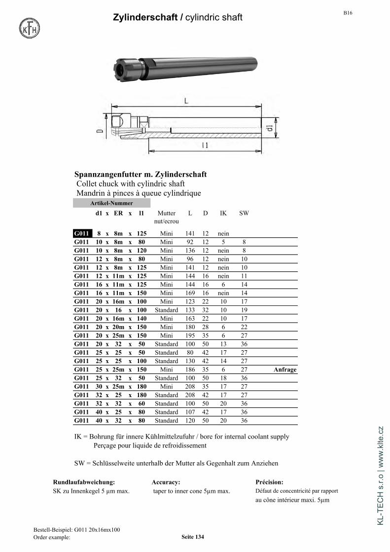
B16Zylinderschaft / cylindric shaft
Spannzangenfutter m. ZylinderschaftCollet chuck with cylindric shaftMandrin à pinces à queue cylindrique
Artikel-Nummer
d1 x ER x l1 Mutter L D IK SWnut/ecrou
G011 8 x 8m x 125 Mini 141 12 neinG011 10 x 8m x 80 Mini 92 12 5 8G011 10 x 8m x 120 Mini 136 12 nein 8G011 12 x 8m x 80 Mini 96 12 nein 10G011 12 x 8m x 125 Mini 141 12 nein 10G011 12 x 11m x 125 Mini 144 16 nein 11G011 16 x 11m x 125 Mini 144 16 6 14G011 16 x 11m x 150 Mini 169 16 nein 14G011 20 x 16m x 100 Mini 123 22 10 17G011 20 x 16 x 100 Standard 133 32 10 19G011 20 x 16m x 140 Mini 163 22 10 17G011 20 x 20m x 150 Mini 180 28 6 22G011 20 x 25m x 150 Mini 195 35 6 27G011 20 x 32 x 50 Standard 100 50 13 36G011 25 x 25 x 50 Standard 80 42 17 27G011 25 x 25 x 100 Standard 130 42 14 27G011 25 x 25m x 150 Mini 186 35 6 27 AnfrageG011 25 x 32 x 50 Standard 100 50 18 36G011 30 x 25m x 180 Mini 208 35 17 27G011 32 x 25 x 180 Standard 208 42 17 27G011 32 x 32 x 60 Standard 100 50 20 36G011 40 x 25 x 80 Standard 107 42 17 36G011 40 x 32 x 80 Standard 120 50 20 36
IK = Bohrung für innere Kühlmittelzufuhr / bore for internal coolant supplyPerçage pour liquide de refroidissement
SW = Schlüsselweite unterhalb der Mutter als Gegenhalt zum Anziehen
Rundlaufabweichung: Accuracy: Précision:SK zu Innenkegel 5 µm max. taper to inner cone 5µm max. Défaut de concentricité par rapport
au cône intérieur maxi. 5µm
Bestell-Beispiel: G011 20x16mx100Order example: Seite 134
KL-T
ECH
s.r.
o | w
ww
.klte
.cz
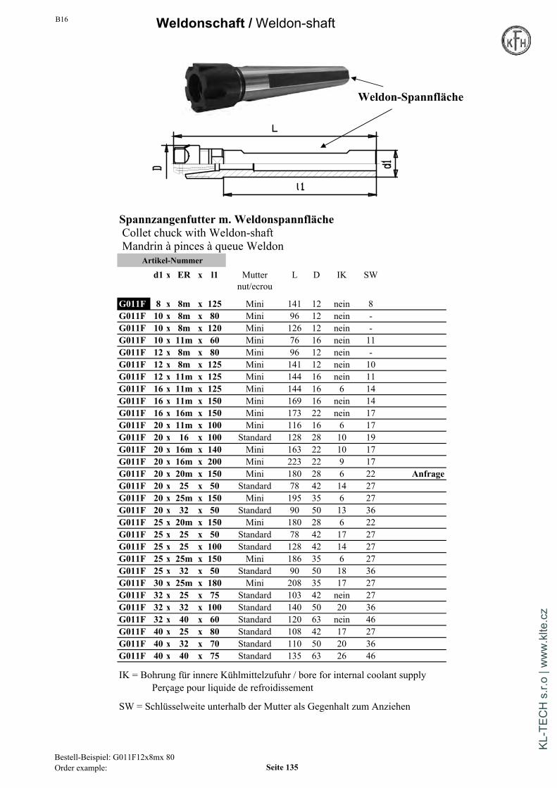
B16 Weldonschaft /Weldon-shaft
Weldon-Spannfläche
Spannzangenfutter m. WeldonspannflächeCollet chuck with Weldon-shaftMandrin à pinces à queue Weldon
Artikel-Nummer
d1 x ER x l1 Mutter L D IK SWnut/ecrou
G011F 8 x 8m x 125 Mini 141 12 nein 8G011F 10 x 8m x 80 Mini 96 12 nein -G011F 10 x 8m x 120 Mini 126 12 nein -G011F 10 x 11m x 60 Mini 76 16 nein 11G011F 12 x 8m x 80 Mini 96 12 nein -G011F 12 x 8m x 125 Mini 141 12 nein 10G011F 12 x 11m x 125 Mini 144 16 nein 11G011F 16 x 11m x 125 Mini 144 16 6 14G011F 16 x 11m x 150 Mini 169 16 nein 14G011F 16 x 16m x 150 Mini 173 22 nein 17G011F 20 x 11m x 100 Mini 116 16 6 17G011F 20 x 16 x 100 Standard 128 28 10 19G011F 20 x 16m x 140 Mini 163 22 10 17G011F 20 x 16m x 200 Mini 223 22 9 17G011F 20 x 20m x 150 Mini 180 28 6 22 AnfrageG011F 20 x 25 x 50 Standard 78 42 14 27G011F 20 x 25m x 150 Mini 195 35 6 27G011F 20 x 32 x 50 Standard 90 50 13 36G011F 25 x 20m x 150 Mini 180 28 6 22G011F 25 x 25 x 50 Standard 78 42 17 27G011F 25 x 25 x 100 Standard 128 42 14 27G011F 25 x 25m x 150 Mini 186 35 6 27G011F 25 x 32 x 50 Standard 90 50 18 36G011F 30 x 25m x 180 Mini 208 35 17 27G011F 32 x 25 x 75 Standard 103 42 nein 27G011F 32 x 32 x 100 Standard 140 50 20 36G011F 32 x 40 x 60 Standard 120 63 nein 46G011F 40 x 25 x 80 Standard 108 42 17 27G011F 40 x 32 x 70 Standard 110 50 20 36G011F 40 x 40 x 75 Standard 135 63 26 46
IK = Bohrung für innere Kühlmittelzufuhr / bore for internal coolant supplyPerçage pour liquide de refroidissement
SW = Schlüsselweite unterhalb der Mutter als Gegenhalt zum Anziehen
Bestell-Beispiel: G011F12x8mx 80Order example: Seite 135
KL-T
ECH
s.r.
o | w
ww
.klte
.cz

B16
Zubehör Accessories
Gewindeschneid-Schnellwechselfutter Hoch-Präz.-Bohrfutter m. Weldonschaftmit Weldonschaft Rechts-/ Linkslauf geeignetmit Längenausgleich auf Druck und Zug High precision drill chuck with Weldon-shaftQuick change tapping chuck with compens. for left- and right-hand rotationwith Weldon-shaft Mandrin de percage, queue WeldonMandrin de taraudage, queue Weldon pour rotation gauche-droiteavec compensation
Artikel-Nummer Artikel-Nummerd x GR A d1 D d x d1 A L1 D
G117 Wel 20 x 1 41 19 38 G134 Wel 20 x 1-13 82 88 50G117 Wel 20 x 2 63 31 55
G134 Wel 25 x 1-13 82 88 50G117 Wel 25 x 1 41 19 38 G134 Wel 25 x 3-16 87 93 57G117 Wel 25 x 2 63 31 55
G134 Wel 32 x 1-13 82 88 50G117 Wel 32 x 1 41 19 38 G134 Wel 32 x 3-16 87 93 57G117 Wel 32 x 2 63 31 55G117 Wel 32 x 3 109 48 79 G134 Wel 40 x 1-13 82 88 50
G134 Wel 40 x 3-16 87 93 57G117 Wel 40 x 1 41 19 38G117 Wel 40 x 2 63 31 55 Mit Schlüssel / with wrench / avec clé de serrageG117 Wel 40 x 3 98 48 79
Rundlaufabweichungmax 20µm bei 3 x d1Ausgleichsweg auf Zug und Druck Max runout: 20µm at 3 x d1Compensation on tension and compression Faux-rond admissible: 20µm max. à 3 x d1Course de compensation traction/pression
Größe 1: je 9 mmGröße 2: je 15 mmGröße 3: je 24 mmTabelle mit Gewindebohrer-Schaftmaßensiehe Seite 138
Tableau avec dimensions des queues de taraudsvoir page 7
Bestell-Beisp.: G134 wel 40x13Order example: G134 wel 40x13 Seite 136
KL-T
ECH
s.r.
o | w
ww
.klte
.cz

B16Technische Information / technical information
CNC-Hoch-Präzisions-BohrfutterArtikelgruppen G134 / G234 / G334 / G434 / G534 / G634
Bezeichnung 08 13 16
Spannbereich 0,3-8 mm 0,5-13 mm 2,5-16 mm DIN2080 Seite 9
Rundlaufabweichung max. 0,02 mm 0,02 mm 0,02 mmbei einem Anzugsmoment von 8 Nm von 15 Nm von 15 Nm
Haltemoment 30 Nm 40 Nm 45 Nmbei einem Anzugsmoment von 10 Nm von 15 Nm von 15 Nm
max.zul.Anzugsmoment 10 Nm 20 Nm 20 Nm S20x2 Seite 17
Haltemoment 80 Nm 90 Nmbei einem Anzugsmoment von 20 Nm von 20 Nm
max.zul. Drehzahl 35.000 min 35.000 min 35.000 min
Alle Hochpräzisions-Bohrfutter werden mittels eines im Lieferumfang DIN69871 Seite 39enthaltenen Sechskant-Schlüssels über einen Kegeltrieb gespannt.Für den Einsatz des Bohrfutters ist ein Anzugsmomentvon 8 Nm bzw. 15 Nm ausreichend.Dabei entsteht ein Haltemoment,am gespannten Werkzeug von 30 Nm,40 Nm bzw.45 Nm (Werte gemessen an einem gereinigtem Hartmetallstift)Die Bohrfutter sind ungewuchtet für einen Einsatz bis 7000 U/min geeignet. MAS BT Seite 71Für die Anwendung bei Drehzahlen über 7000 U/min müssendie Bohrfutter gegen Aufpreis feingewuchtet werden.Die Bohrfutter sind Rechts- / Linkslauf geeignet
CNC high-precision drill chuck Morsekegel Seite 83
Article ranges G134 / G234 / G334 / G434 / G534 / G634
Sizes 08 13 16
Clamping range 0,3-8 mm 0,5-13 mm 2,5-16 mm
Run-Out max. 0,02 mm 0,02 mm 0,02 mmat a tightening torque of 8 Nm of 15 Nm of 15 Nm HSK Seite 103
Clamping force 30 Nm 40 Nm 45 Nmat a tightening torque of 10 Nm of 15 Nm of 15 Nm
max.permissible torque 10 Nm 20 Nm 20 Nm
Clamping force 80 Nm 90 Nmat a tightening torque of 20 Nm of 20 Nm Weldon-Schaft Seite 136
max.permissible rpm 35.000 min 35.000 min 35.000 min
All High-precision-drillchucks are clamped with a hexagon-wrench whichis included in delivery. The recommended tightening torque is 8Nm forclamping range to 8mm and 15Nm for the ranges 13mm / 16 mm.The drill chucks have a reliable pinion-bevel gear driveThe drill chucks are suitable without special balancing for 7.000 rpm. VDI Seite 131In case of higher needed rotations they have to fine-balanced for a uplift price.The drill chucks are suitable for clockwise and counterclockwise rotation.
Seite 137
KL-T
ECH
s.r.
o | w
ww
.klte
.cz
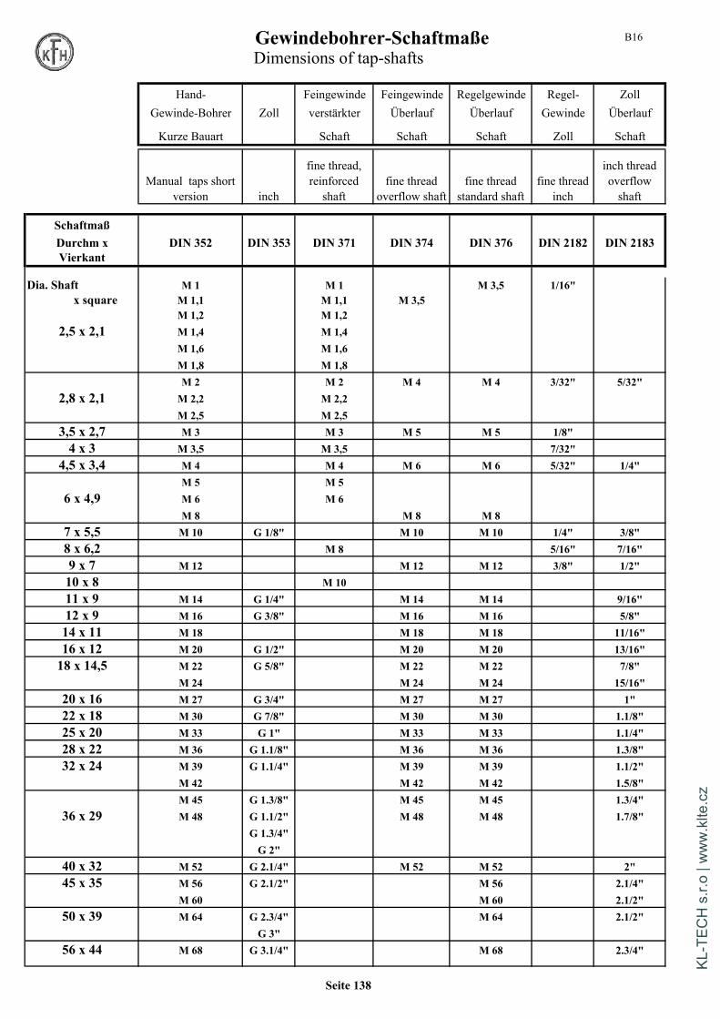
B16Gewindebohrer-SchaftmaßeDimensions of tap-shafts
Hand- Feingewinde Feingewinde Regelgewinde Regel- ZollGewinde-Bohrer Zoll verstärkter Überlauf Überlauf Gewinde Überlauf
Kurze Bauart Schaft Schaft Schaft Zoll Schaft
Manual taps shortversion inch
fine thread,reinforcedshaft
fine threadoverflow shaft
fine threadstandard shaft
fine threadinch
inch threadoverflowshaft
SchaftmaßDurchm x DIN 352 DIN 353 DIN 371 DIN 374 DIN 376 DIN 2182 DIN 2183Vierkant
Dia. Shaft M 1 M 1 M 3,5 1/16"x square M 1,1 M 1,1 M 3,5
M 1,2 M 1,22,5 x 2,1 M 1,4 M 1,4
M 1,6 M 1,6M 1,8 M 1,8M 2 M 2 M 4 M 4 3/32" 5/32"
2,8 x 2,1 M 2,2 M 2,2M 2,5 M 2,5
3,5 x 2,7 M 3 M 3 M 5 M 5 1/8"4 x 3 M 3,5 M 3,5 7/32"
4,5 x 3,4 M 4 M 4 M 6 M 6 5/32" 1/4"M 5 M 5
6 x 4,9 M 6 M 6M 8 M 8 M 8
7 x 5,5 M 10 G 1/8" M 10 M 10 1/4" 3/8"8 x 6,2 M 8 5/16" 7/16"9 x 7 M 12 M 12 M 12 3/8" 1/2"10 x 8 M 1011 x 9 M 14 G 1/4" M 14 M 14 9/16"12 x 9 M 16 G 3/8" M 16 M 16 5/8"14 x 11 M 18 M 18 M 18 11/16"16 x 12 M 20 G 1/2" M 20 M 20 13/16"18 x 14,5 M 22 G 5/8" M 22 M 22 7/8"
M 24 M 24 M 24 15/16"20 x 16 M 27 G 3/4" M 27 M 27 1"22 x 18 M 30 G 7/8" M 30 M 30 1.1/8"25 x 20 M 33 G 1" M 33 M 33 1.1/4"28 x 22 M 36 G 1.1/8" M 36 M 36 1.3/8"32 x 24 M 39 G 1.1/4" M 39 M 39 1.1/2"
M 42 M 42 M 42 1.5/8"M 45 G 1.3/8" M 45 M 45 1.3/4"
36 x 29 M 48 G 1.1/2" M 48 M 48 1.7/8"G 1.3/4"G 2"
40 x 32 M 52 G 2.1/4" M 52 M 52 2"45 x 35 M 56 G 2.1/2" M 56 2.1/4"
M 60 M 60 2.1/2"50 x 39 M 64 G 2.3/4" M 64 2.1/2"
G 3"56 x 44 M 68 G 3.1/4" M 68 2.3/4"
Seite 138
KL-T
ECH
s.r.
o | w
ww
.klte
.cz

B16 Zubehör Accessories
Einsätze für Gewindeschneidfutter Einsätze für Gewindeschneidfuttermit Sicherheitskupplung ohne SicherheitskupplungTapping collets with clutch Tapping collets without clutchDouille avec limiteur de couple Douille sans limiteur de coupleArtikel-Nummer Artikel-Nummer
Größe d1 x Vierk d D Größe d1 x Vierk d DG013 1 mit 2,8 x 2,1 19 32 G013 1 ohne 2,8 x 2,1 19 32G013 1 mit 3,15 x 2,5 19 32 auf Anfrage G013 1 ohne 3,15 x 2,5 19 32 auf AnfrageG013 1 mit 3,5 x 2,7 19 32 G013 1 ohne 3,5 x 2,7 19 32G013 1 mit 4 x 3 19 32 G013 1 ohne 4 x 3 19 32G013 1 mit 4 x 3,2 19 32 G013 1 ohne 4 x 3,2 19 32 auf AnfrageG013 1 mit 4,5 x 3,4 19 32 G013 1 ohne 4,5 x 3,4 19 32G013 1 mit 5 x 4 19 32 auf Anfrage G013 1 ohne 5 x 4 19 32 auf AnfrageG013 1 mit 6 x 4,9 19 32 G013 1 ohne 6 x 4,9 19 32G013 1 mit 6 x 4,9M5 19 32G013 1 mit 6,3 x 5 19 32 auf Anfrage G013 1 ohne 6,3 x 5 19 32 auf AnfrageG013 1 mit 7 x 5,5 19 32 1 ohne 7 x 5,5 19 32G013 1 mit 8 x 6,2 19 32 G013 1 ohne 8 x 6,2 19 32G013 1 mit 9 x 7 19 32 G013 1 ohne 9 x 7 19 32G013 1 mit 10 x 8 19 32 G013 1 ohne 10 x 8 19 32G013 1 mit 11 x 9 19 32 G013 1 ohne 11 x 9 19 32G013 1 mit 12 x 9 19 32 G013 1 ohne 12 x 9 19 32G013 2 mit 6 x 4,9 31 50 G013 2 ohne 6 x 4,9 31 50G013 2 mit 6,3 x 5 31 50 auf Anfrage G013 2 ohne 6,3 x 5 31 50 auf AnfrageG013 2 mit 7 x 5,5 31 50 G013 2 ohne 7 x 5,5 31 50G013 2 mit 8 x 6,2 31 50 G013 2 ohne 8 x 6,2 31 50G013 2 mit 9 x 7 31 50 G013 2 ohne 9 x 7 31 50G013 2 mit 10 x 8 31 50 G013 2 ohne 10 x 8 31 50G013 2 mit 11 x 9 31 50 G013 2 ohne 11 x 9 31 50G013 2 mit 11,2 x 9 31 50 auf Anfrage G013 2 ohne 11,2 x 9 31 50 auf AnfrageG013 2 mit 12 x 9 31 50 G013 2 ohne 12 x 9 31 50G013 2 mit 12,5 x 10 31 50 auf Anfrage G013 2 ohne 12,5 x 10 31 50 auf AnfrageG013 2 mit 14 x 11 31 50 G013 2 ohne 14 x 11 31 50G013 2 mit 14 x 11,2 31 50 auf Anfrage G013 2 ohne 14 x 11,2 31 50 auf AnfrageG013 2 mit 16 x 12 31 50 G013 2 ohne 16 x 12 31 50G013 2 mit 16 x 12,5 31 50 auf Anfrage G013 2 ohne 16 x 12,5 31 50 auf AnfrageG013 2 mit 18 x 14,5 31 50 G013 2 ohne 18 x 14,5 31 50G013 2 mit 20 x 16 31 50 G013 2 ohne 20 x 16 31 50G013 3 mit 11 x 9 48 72 G013 3 ohne 11 x 9 48 72G013 3 mit 12 x 9 48 72 G013 3 ohne 12 x 9 48 72G013 3 mit 14 x 11 48 72 G013 3 ohne 14 x 11 48 72G013 3 mit 16 x 12 48 72 G013 3 ohne 16 x 12 48 72G013 3 mit 18 x 14,5 48 72 G013 3 ohne 18 x 14,5 48 72G013 3 mit 20 x 16 48 72 G013 3 ohne 20 x 16 48 72G013 3 mit 22 x 18 48 72 G013 3 ohne 22 x 18 48 72G013 3 mit 25 x 20 48 72 G013 3 ohne 25 x 20 48 72G013 3 mit 28 x 22 48 72 G013 3 ohne 28 x 22 48 72
Bestell-Beispiel: G013 2mit 8,0x6,2Order example: Seite 139
KL-T
ECH
s.r.
o | w
ww
.klte
.cz

B16Zubehör Accessories
Spannzangen OZ DIN 6388B Spannzangen OZ DIN 6388BCollet OZ DIN 6388B Collet OZ DIN 6388BPinces de serrage OZ DIN 6388B Pinces de serrage OZ DIN 6388B
OZ x d D L OZ x d D L
G016 16 x 2,0 25,5 40 415 E G016 32 x 3,0 44 60 467 EG016 16 x 3,0 25,5 40 415 E G016 32 x 4,0 44 60 467 EG016 16 x 4,0 25,5 40 415 E G016 32 x 5,0 44 60 467 EG016 16 x 5,0 25,5 40 415 E G016 32 x 6,0 44 60 467 EG016 16 x 6,0 25,5 40 415 E G016 32 x 7,0 44 60 467 EG016 16 x 7,0 25,5 40 415 E G016 32 x 8,0 44 60 467 EG016 16 x 8,0 25,5 40 415 E G016 32 x 9,0 44 60 467 EG016 16 x 9,0 25,5 40 415 E G016 32 x 10,0 44 60 467 EG016 16 x 10,0 25,5 40 415 E G016 x 11,0 44 60 467 EG016 16 x 11,0 25,5 40 415 E G016 32 x 12,0 44 60 467 EG016 16 x 12,0 25,5 40 415 E G016 32 x 13,0 44 60 467 EG016 16 x 13,0 25,5 40 415 E G016 32 x 14,0 44 60 467 EG016 16 x 14,0 25,5 40 415 E G016 32 x 15,0 44 60 467 EG016 16 x 15,0 25,5 40 415 E G016 32 x 16,0 44 60 467 EG016 16 x 16,0 25,5 40 415 E G016 32 x 17,0 44 60 467 E
G016 32 x 18,0 44 60 467 EG016 OZ x d D L G016 32 x 19,0 44 60 467 E
G016 25 x 2,0 35,05 52 462 E G016 32 x 20,0 44 60 467 EG016 25 x 3,0 35,05 52 462 E G016 32 x 21,0 44 60 467 EG016 25 x 4,0 35,05 52 462 E G016 32 x 22,0 44 60 467 EG016 25 x 5,0 35,05 52 462 E G016 32 x 23,0 44 60 467 EG016 25 x 6,0 35,05 52 462 E G016 32 x 24,0 44 60 467 EG016 25 x 7,0 35,05 52 462 E G016 32 x 25,0 44 60 467 EG016 25 x 8,0 35,05 52 462 E G016 32 x 26,0 44 60 467 EG016 25 x 9,0 35,05 52 462 E G016 32 x 27,0 44 60 467 EG016 25 x 10,0 35,05 52 462 E G016 32 x 28,0 44 60 467 EG016 25 x 11,0 35,05 52 462 E G016 32 x 29,0 44 60 467 EG016 25 x 12,0 35,05 52 462 E G016 32 x 30,0 44 60 467 EG016 25 x 13,0 35,05 52 462 E G016 32 x 31,0 44 60 467 EG016 25 x 14,0 35,05 52 462 E G016 32 x 32,0 44 60 467 EG016 25 x 15,0 35,05 52 462 EG016 25 x 16,0 35,05 52 462 EG016 25 x 17,0 35,05 52 462 EG016 25 x 18,0 35,05 52 462 EG016 25 x 19,0 35,05 52 462 EG016 25 x 20,0 35,05 52 462 EG016 25 x 21,0 35,05 52 462 E Max. Spannbereich = 0,4mm unter NennmaßG016 25 x 22,0 35,05 52 462 E Max. clamp.-range = 0,4 mm below nominal diameterG016 25 x 23,0 35,05 52 462 EG016 25 x 24,0 35,05 52 462 E Zwischenmaße 0,5 mm auf AnfrageG016 25 x 25,0 35,05 52 462 E Tailles intermédiaires 0,5 mm sur demande
Rundlaufabweichung: 1-10mm = 15µm max.run-out accuracy: 11-25mm = 20µmmax.defaut de concentricite: 26-32mm = 25µm max.
Bestell-Beispiel: G016 25 x 10Order example: Seite 140
KL-T
ECH
s.r.
o | w
ww
.klte
.cz

B16
Zubehör Accessories
Reduzierbüchsen f. Hydrodehn-Spann- Spannmutter OZ DIN 6388Dfutter und Kraftspannfutter Nut for collet OZ DIN 6388DCollet for hydraulic chuck Ecrou de serrage OZ DIN 6388Dand High Power milling chuckDouille de réduction mandrin hydrauliques Artikel-Nummer Gewindeet mandrin a fort serrage L D Filetage
Artikel-Nummer G018 16 Standard 24 43 M33x1,5D x d1 L l1 G018 30 60 M48x2
G018 32 Standard 34 72 M60x2,5G014a 20 x 6 52 49 G018gw 16 gewuchtet 24 43 M33x1,5G014a 20 x 8 52 49 G018gw 25 gewuchtet 30 60 M48x2G014a 20 x 10 52 49 G018IK 16 f. KüMittel 32 43 M33x1,5G014a 20 x 12 52 49 G018IK 25 f. KüMittel 38 60 M48x2G014a 20 x 16 52 49 G018IK 32 f. KüMittel 43 72 M60x2,5
G018DR 16 Dichtring Drm angebenG014a 32 x 10 63 59 G018DR 25 Dichtring Indicate diameterG014a 32 x 12 63 59 G018DR 32 Dichtring Indiquer le ØG014a 32 x 14 63 59G014a 32 x 16 63 59G014a 32 x 18 63 59G014a 32 x 20 63 59G014a 32 x 25 63 59abgedichtet für IKsealed for internal coolant Hakenschlüssel für Typ OZEtanche pour arrosage interne Wrench for type OZ
Clé pour type OZ fürArtikel-Nummer Durchm.
G017 für OZ16 415E 40-42
G017 für OZ20 4541E 45-50G017 für OZ25 462E 58-62G017 für OZ32 467E 68-75
Drm 20mm ohne AbdichtungAuf Anfrage
Dia 20mm without sealingon request
Dia 20mm non etanchesur demande
Bestell-Beispiel: G014a 20x10Order example: Seite 141
KL-T
ECH
s.r.
o | w
ww
.klte
.cz
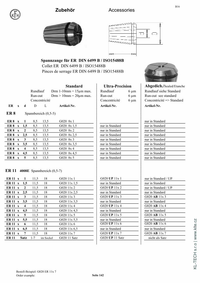
B16Zubehör Accessories
Spannzange für ER DIN 6499 B / ISO15488BCollet ER DIN 6499 B / ISO15488BPinces de serrage ER DIN 6499 B / ISO15488B
Standard Ultra-Precision Abgedich./Sealed/EtancheRundlauf Drm 1-10mm = 15µm max. Rundlauf 6 µm Rundlauf siehe StandardRun-out Drm > 10mm = 20µm max. Run-out 6 µm Run-out see standardConcentricité Concentricité 6 µm Concentricité => Standard
ER x d D L Artikel-Nr. Artikel-Nr. Artikel-Nr.
ER 8 Spannbereich (0,5-5)
ER 8 x 1 8,5 13,5 G020 8x 1 nur in StandardER 8 x 1,5 8,5 13,5 G020 8x 1,5 nur in Standard nur in StandardER 8 x 2 8,5 13,5 G020 8x 2 nur in Standard nur in StandardER 8 x 2,5 8,5 13,5 G020 8x 2,5 nur in Standard nur in StandardER 8 x 3 8,5 13,5 G020 8x 3 nur in Standard nur in StandardER 8 x 3,5 8,5 13,5 G020 8x 3,5 nur in Standard nur in StandardER 8 x 4 8,5 13,5 G020 8x 4 nur in Standard nur in StandardER 8 x 4,5 8,5 13,5 G020 8x 4,5 nur in Standard nur in StandardER 8 x 5 8,5 13,5 G020 8x 5 nur in Standard nur in Standard
ER 11 4008E Spannbereich (0,5-7)
ER 11 x 1 11,5 18 G020 11x 1 G020 UP 11x 1 nur in Standard / UPER 11 x 1,5 11,5 18 G020 11x 1,5 nur in Standard nur in StandardER 11 x 2 11,5 18 G020 11x 2 G020 UP 11x 2 nur in Standard / UPER 11 x 2,5 11,5 18 G020 11x 2,5 nur in Standard nur in StandardER 11 x 3 11,5 18 G020 11x 3 G020 UP 11x 3 G020 AB 11x 3ER 11 x 3,5 11,5 18 G020 11x 3,5 nur in Standard nur in StandardER 11 x 4 11,5 18 G020 11x 4 G020 UP 11x 4 G020 AB 11x 4ER 11 x 4,5 11,5 18 G020 11x 4,5 nur in Standard nur in StandardER 11 x 5 11,5 18 G020 11x 5 G020 UP 11x 5 G020 AB 11x 5ER 11 x 5,5 11,5 18 G020 11x 5,5 nur in Standard nur in StandardER 11 x 6 11,5 18 G020 11x 6 G020 UP 11x 6 G020 AB 11x 6ER 11 x 6,5 11,5 18 G020 11x 6,5 nur in Standard nur in StandardER 11 x 7 11,5 18 G020 11x 7 G020 UP 11x 7 G020 AB 11x 7ER 11 Satz 1-7 im Sockel G020 11 Satz G020 UP 11 Satz nicht als Satz
Bestell-Beispiel: G020 ER 11x 7Order example: Seite 142
KL-T
ECH
s.r.
o | w
ww
.klte
.cz
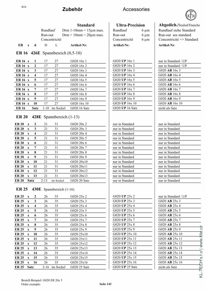
B16 Zubehör Accessories
Standard Ultra-Precision Abgedich./Sealed/EtancheRundlauf Drm 1-10mm = 15µm max. Rundlauf 6 µm Rundlauf siehe StandardRun-out Drm > 10mm = 20µm max. Run-out 6 µm Run-out see standardConcentricité Concentricité 6 µm Concentricité => Standard
ER x d D L Artikel-Nr. Artikel-Nr. Artikel-Nr.
ER 16 426E Spannbereich (0,5-10)
ER 16 x 1 17 27 G020 16x 1 G020 UP 16x 1 nur in Standard / UPER 16 x 2 17 27 G020 16x 2 G020 UP 16x 2 nur in Standard / UPER 16 x 3 17 27 G020 16x 3 G020 UP 16x 3 G020 AB 16x 3ER 16 x 4 17 27 G020 16x 4 G020 UP 16x 4 G020 AB 16x 4ER 16 x 5 17 27 G020 16x 5 G020 UP 16x 5 G020 AB 16x 5ER 16 x 6 17 27 G020 16x 6 G020 UP 16x 6 G020 AB 16x 6ER 16 x 7 17 27 G020 16x 7 G020 UP 16x 7 G020 AB 16x 7ER 16 x 8 17 27 G020 16x 8 G020 UP 16x 8 G020 AB 16x 8ER 16 x 9 17 27 G020 16x 9 G020 UP 16x 9 G020 AB 16x 9ER 16 x 10 17 27 G020 16x 10 G020 UP 16x 10 G020 AB 16x 10ER 16 Satz 1-10 im Sockel G020 16 Satz G020 UP 16 Satz nicht als Satz
ER 20 428E Spannbereich (1-13)ER 20 x 2 21 31 G020 20x 2 nur in Standard nur in StandardER 20 x 3 21 31 G020 20x 3 nur in Standard nur in StandardER 20 x 4 21 31 G020 20x 4 nur in Standard nur in StandardER 20 x 5 21 31 G020 20x 5 nur in Standard nur in StandardER 20 x 6 21 31 G020 20x 6 nur in Standard nur in StandardER 20 x 7 21 31 G020 20x 7 nur in Standard nur in StandardER 20 x 8 21 31 G020 20x 8 nur in Standard nur in StandardER 20 x 9 21 31 G020 20x 9 nur in Standard nur in StandardER 20 x 10 21 31 G020 20x10 nur in Standard nur in StandardER 20 x 11 21 31 G020 20x11 nur in Standard nur in StandardER 20 x 12 21 31 G020 20x12 nur in Standard nur in StandardER 20 x 13 21 31 G020 20x13 nur in Standard nur in StandardER 20 Satz 2-13 im Sockel G020 20 Satz nur in Standard nur in Standard
ER 25 430E Spannbereich (1-16)
ER 25 x 2 26 35 G020 25x 2 G020 UP 25x 2 nur in Standard / UPER 25 x 3 26 35 G020 25x 3 G020 UP 25x 3 G020 AB 25x 3ER 25 x 4 26 35 G020 25x 4 G020 UP 25x 4 G020 AB 25x 4ER 25 x 5 26 35 G020 25x 5 G020 UP 25x 5 G020 AB 25x 5ER 25 x 6 26 35 G020 25x 6 G020 UP 25x 6 G020 AB 25x 6ER 25 x 7 26 35 G020 25x 7 G020 UP 25x 7 G020 AB 25x 7ER 25 x 8 26 35 G020 25x 8 G020 UP 25x 8 G020 AB 25x 8ER 25 x 9 26 35 G020 25x 9 G020 UP 25x 9 G020 AB 25x 9ER 25 x 10 26 35 G020 25x10 G020 UP 25x 10 G020 AB 25x 10ER 25 x 11 26 35 G020 25x11 G020 UP 25x 11 G020 AB 25x 11ER 25 x 12 26 35 G020 25x12 G020 UP 25x 12 G020 AB 25x 12ER 25 x 13 26 35 G020 25x13 G020 UP 25x 13 G020 AB 25x 13ER 25 x 14 26 35 G020 25x14 G020 UP 25x 14 G020 AB 25x 14ER 25 x 15 26 35 G020 25x15 G020 UP 25x 15 G020 AB 25x 15ER 25 x 16 26 35 G020 25x16 G020 UP 25x 16 G020 AB 25x 16ER 25 Satz 2-16 im Sockel G020 25 Satz G020 UP 25 Satz nicht als Satz
Bestell-Beispiel: G020 ER 20x 5Order example: Seite 143
KL-T
ECH
s.r.
o | w
ww
.klte
.cz
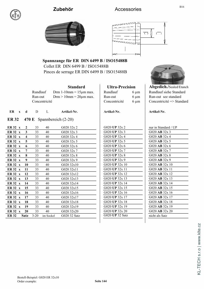
B16Zubehör Accessories
Spannzange für ER DIN 6499 B / ISO15488BCollet ER DIN 6499 B / ISO15488BPinces de serrage ER DIN 6499 B / ISO15488B
Standard Ultra-Precision Abgedich./Sealed/EtanchRundlauf Drm 1-10mm = 15µm max. Rundlauf 6 µm Rundlauf siehe StandardRun-out Drm > 10mm = 20µm max. Run-out 6 µm Run-out see standardConcentricité Concentricité 6 µm Concentricité => Standard
ER x d D L Artikel-Nr. Artikel-Nr. Artikel-Nr.
ER 32 470 E Spannbereich (2-20)
ER 32 x 2 33 40 G020 32x 2 G020 UP 32x 2 nur in Standard / UPER 32 x 3 33 40 G020 32x 3 G020 UP 32x 3 G020 AB 32x 3ER 32 x 4 33 40 G020 32x 4 G020 UP 32x 4 G020 AB 32x 4ER 32 x 5 33 40 G020 32x 5 G020 UP 32x 5 G020 AB 32x 5ER 32 x 6 33 40 G020 32x 6 G020 UP 32x 6 G020 AB 32x 6ER 32 x 7 33 40 G020 32x 7 G020 UP 32x 7 G020 AB 32x 7ER 32 x 8 33 40 G020 32x 8 G020 UP 32x 8 G020 AB 32x 8ER 32 x 9 33 40 G020 32x 9 G020 UP 32x 9 G020 AB 32x 9ER 32 x 10 33 40 G020 32x10 G020 UP 32x 10 G020 AB 32x 10ER 32 x 11 33 40 G020 32x11 G020 UP 32x 11 G020 AB 32x 11ER 32 x 12 33 40 G020 32x12 G020 UP 32x 12 G020 AB 32x 12ER 32 x 13 33 40 G020 32x13 G020 UP 32x 13 G020 AB 32x 13ER 32 x 14 33 40 G020 32x14 G020 UP 32x 14 G020 AB 32x 14ER 32 x 15 33 40 G020 32x15 G020 UP 32x 15 G020 AB 32x 15ER 32 x 16 33 40 G020 32x16 G020 UP 32x 16 G020 AB 32x 16ER 32 x 17 33 40 G020 32x17 G020 UP 32x 17 G020 AB 32x 17ER 32 x 18 33 40 G020 32x18 G020 UP 32x 18 G020 AB 32x 18ER 32 x 19 33 40 G020 32x19 G020 UP 32x 19 G020 AB 32x 19ER 32 x 20 33 40 G020 32x20 G020 UP 32x 20 G020 AB 32x 20ER 32 Satz 3-20 im Sockel G020 32 Satz G020 UP 32 Satz nicht als Satz
Bestell-Beispiel: G020 ER 32x10Order example: Seite 144
KL-T
ECH
s.r.
o | w
ww
.klte
.cz

B16Zubehör Accessories
Standard Ultra-Precision Abgedich./Sealed/EtanchRundlauf Drm 1-10mm = 15µm max. Rundlauf 6 µm Rundlauf siehe StandardRun-out Drm > 10mm = 20µm max. Run-out 6 µm Run-out see standardConcentricité Concentricité 6 µm Concentricité => Standard
ER x d D L Artikel-Nr. Artikel-Nr. Artikel-Nr.
ER 40 472 E Spannbereich (3-30)
ER 40 x 3 41 46 G020 40x 3 G020 UP 40x 3 nur in Standard / UPER 40 x 4 41 46 G020 40x 4 G020 UP 40x 4 nur in Standard / UPER 40 x 5 41 46 G020 40x 5 G020 UP 40x 5 G020 AB 40x 5ER 40 x 6 41 46 G020 40x 6 G020 UP 40x 6 G020 AB 40x 6ER 40 x 7 41 46 G020 40x 7 G020 UP 40x 7 G020 AB 40x 7ER 40 x 8 41 46 G020 40x 8 G020 UP 40x 8 G020 AB 40x 8ER 40 x 9 41 46 G020 40x 9 G020 UP 40x 9 G020 AB 40x 9ER 40 x 10 41 46 G020 40x10 G020 UP 40x 10 G020 AB 40x 10ER 40 x 11 41 46 G020 40x11 G020 UP 40x 11 G020 AB 40x 11ER 40 x 12 41 46 G020 40x12 G020 UP 40x 12 G020 AB 40x 12ER 40 x 13 41 46 G020 40x13 G020 UP 40x 13 G020 AB 40x 13ER 40 x 14 41 46 G020 40x14 G020 AB 40x 14ER 40 x 15 41 46 G020 40x15 G020 UP 40x 15 G020 AB 40x 15ER 40 x 16 41 46 G020 40x16 G020 UP 40x 16 G020 AB 40x 16ER 40 x 17 41 46 G020 40x17 G020 UP 40x 17 G020 AB 40x 17ER 40 x 18 41 46 G020 40x18 G020 UP 40x 18 G020 AB 40x 18ER 40 x 19 41 46 G020 40x19 G020 UP 40x 19 G020 AB 40x 19ER 40 x 20 41 46 G020 40x20 G020 UP 40x 20 G020 AB 40x 20ER 40 x 21 41 46 G020 40x21 G020 UP 40x 21 G020 AB 40x 21ER 40 x 22 41 46 G020 40x22 G020 UP 40x 22 G020 AB 40x 22ER 40 x 23 41 46 G020 40x23 G020 UP 40x 23 G020 AB 40x 23ER 40 x 24 41 46 G020 40x24 G020 UP 40x 24 G020 AB 40x 24ER 40 x 25 41 46 G020 40x25 G020 UP 40x 25 G020 AB 40x 25ER 40 x 26 41 46 G020 40x26 G020 UP 40x 26 G020 AB 40x 26ER 40 x 27 41 46 G020 40x27 G020 UP 40x 27 auf Anfrage nur in Standard / UPER 40 x 28 41 46 G020 40x28 G020 UP 40x 28 auf Anfrage nur in Standard / UPER 40 x 29 41 46 G020 40x29 G020 UP 40x 29 auf Anfrage nur in Standard / UPER 40 x 30 41 46 G020 40x30 G020 UP 40x 30 auf Anfrage nur in Standard / UPER 40 Satz 4-26 im Sockel G020 40 Satz G020 UP 40 Satz nicht als Satz
ER 50 474 E Spannbereich (5-34)ER 50 x 6 52 60 G020 50x 6 nur in Standard nur in StandardER 50 x 8 52 60 G020 50x 8 nur in Standard nur in StandardER 50 x 10 52 60 G020 50x 10 nur in Standard nur in StandardER 50 x 12 52 60 G020 50x 12 nur in Standard nur in StandardER 50 x 14 52 60 G020 50x 14 nur in Standard nur in StandardER 50 x 16 52 60 G020 50x 16 nur in Standard nur in StandardER 50 x 18 52 60 G020 50x 18 nur in Standard nur in StandardER 50 x 20 52 60 G020 50x 20 nur in Standard nur in StandardER 50 x 22 52 60 G020 50x 22 nur in Standard nur in StandardER 50 x 24 52 60 G020 50x 24 nur in Standard nur in StandardER 50 x 26 52 60 G020 50x 26 nur in Standard nur in StandardER 50 x 28 52 60 G020 50x 28 nur in Standard nur in StandardER 50 x 30 52 60 G020 50x 30 nur in Standard nur in StandardER 50 x 32 52 60 G020 50x 32 nur in Standard nur in StandardER 50 x 34 52 60 G020 50x 34 nur in Standard nur in Standard
Bestell-Beispiel: G020 ER 40x 5Order example: Seite 145
KL-T
ECH
s.r.
o | w
ww
.klte
.cz

B16Zubehör Accessories
Gewindebohrzangen mit Innenvierkant Gewindebohrzangen mit InnenvierkantTapping collets with internal square Tapping collets with internal squarePinces de taraudage avec carré intérieur Pinces de taraudage avec carré intérieur
Artikel-Nummer Artikel-Nummer
ER x d Vierk L ER x d Vierk LER 16 Squar ER 32 Squar
G022V ER 16 x 3,5 2,7 27,5 G022V ER 32 x 3,5 2,7 40G022V ER 16 x 4 3 27,5 G022V ER 32 x 4 3 40G022V ER 16 x 4,5 3,4 27,5 G022V ER 32 x 4,5 3,4 40G022V ER 16 x 6 4,9 27,5 G022V ER 32 x 6 4,9 40G022V ER 16 x 7 5,5 27,5 G022V ER 32 x 7 5,5 40G022V ER 16 x 8 6,2 27,5 G022V ER 32 x 8 6,2 40G022V ER 16 x 9 7 27,5 G022V ER 32 x 9 7 40
G022V ER 32 x 10 8 40G022V ER 32 x 11 9 40G022V ER 32 x 12 9 40
ER 25 G022V ER 32 x 14 11 40G022V ER 25 x 3,5 2,7 34 G022V ER 32 x 16 12 40G022V ER 25 x 4 3 34 G022V ER 32 x 18 14,5 40G022V ER 25 x 4,5 3,4 34G022V ER 25 x 6 4,9 34 ER 40G022V ER 25 x 7 5,5 34 G022V ER 40 x 6 4,9 46G022V ER 25 x 8 6,2 34 G022V ER 40 x 7 5,5 46G022V ER 25 x 9 7 34 G022V ER 40 x 8 6,2 46G022V ER 25 x 10 8 34 G022V ER 40 x 9 7 46G022V ER 25 x 11 9 34 G022V ER 40 x 10 8 46G022V ER 25 x 12 9 34 G022V ER 40 x 11 9 46G022V ER 25 x 14 11 34 G022V ER 40 x 12 9 46G022V ER 25 x 16 12 34 G022V ER 40 x 14 11 46
G022V ER 40 x 16 12 46G022V ER 40 x 18 14,5 46G022V ER 40 x 20 16 46G022V ER 40 x 22 18 46
Bestell-Beispiel: G022V 25x 8Order example: Seite 146
KL-T
ECH
s.r.
o | w
ww
.klte
.cz

B16
Drehmoment - Tabelle für Spannfutter WeldonRecommended tightening torque for Endmill-holders WeldonTableau de couples recommandés pour mandrins de serrage Weldon
Weldon-Drm Schraube Drehmoment Schraubenvorspannung Pré-serrage écrouØ Weldon Ecrou Couple min.(µ=0,18) max.(µ=0,12)
6 M6 5 Nm 4 500 N 6 200 N8 M8 10 Nm 6 700 N 9 400 N10 M10 15 Nm 8 000 N 11 300 N12 M12 20 Nm 8 900 N 12 600 N14 M12 20 Nm 8 900 N 12 600 N16 M14 25 Nm 9 600 N 13 500 N18 M14 25 Nm 9 600 N 13 500 N20 M16 30 Nm 10 000 N 14 400 N25 M18x2 35 Nm 10 500 N 15 000 N32 M20x2 40 Nm 10 800 N 15 600 N40 M20x2 40 Nm 10 800 N 15 600 N
Anzugsdrehmoment für ER-SpannzangenmutterRecommended tightening torque for ER Collet chuck nutsCouples recommandés pour écrous de pinces de serrage ER
Spannzangen Größe Gewinde Max. AnzugsmomentSize of collet Thread Max. torqueTaille de la pince Filetage Force de serrage maxi.
ER 8 ( 1- 5mm) M10x0,75 6 NmER 11 ( 1- 7mm) M13x0,75 20 NmER 16 ( 1-10mm) M22x1,5 70 NmER 20 ( 1-13mm) M25x1,5 75 NmER 25 ( 1-16mm) M32x1,5 85 NmER 32 ( 2-20mm) M40x1,5 105 NmER 40 ( 3-26mm) M50x1,5 150 Nm
Handhabung von ER-Spannzange und SpannmutterHandling of ER collets and ER-collet-nuts / Utilisation de la pince de serrage et de l'écrou
Pour le montage de la pince dans l'écrou, la pince est positionnée de manière oblique et encliquetéedans l'excentrique de l'écrou. Avec la pince ainsi mise en place, l'écrou est vissé sur le mandrin à pince.En dévissat l'écrou, la pince se desserre automatiquement et l'outil peut être enlevé aisément.
Zur Montage der Spannzange in die Spannmutter wird dieZange schräg angesetzt und in den Exzenter der Muttereingerastet.Die Mutter wird mit eingesetzter Zange auf dasSpannzangenfutter aufgeschraubt.Beim Lösen der Mutter entspannt die Zange selbsttätig,das Werkzeug läßt sich leicht entnehmen.
To connect the collet in the nut, the collet must be inserted at an angle and then clicked straight. The colletmust be correctly fitted to the nut before the nut is screwed on to the collet chuck. When the nut is loosened thecollet is released automatically allowing the cutting tool to be easily removed.
Seite 147
KL-T
ECH
s.r.
o | w
ww
.klte
.cz
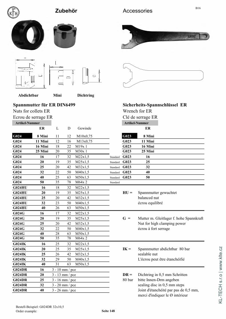
B16Zubehör Accessories
Abdichtbar Mini Dichtring
Spannmutter für ER DIN6499 Sicherheits-Spannschlüssel ERNuts for collets ER Wrench for EREcrou de serrage ER Clé de serrage ERArtikel-Nummer Artikel-Nummer
ER L D Gewinde ER
G024 8 Mini 11 12 M10x0,75 G023 8 MiniG024 11 Mini 12 16 M13x0,75 G023 11 MiniG024 16 Mini 18 22 M19x 1 G023 16 MiniG024 25 Mini 20 35 M30x 1 G023 25 MiniG024 16 17 32 M22x1,5 Standard G023 16G024 20 19 35 M25x1,5 Standard G023 25G024 25 20 42 M32x1,5 Standard G023 32G024 32 22 50 M40x1,5 Standard G023 40G024 40 25 63 M50x1,5 Standard G023 50G024 50 35 78 M64x 2 Standard
G024HU 16 18 32 M22x1,5G024HU 20 19 35 M25x1,5 HU = Spannmutter gewuchtetG024HU 25 20 42 M32x1,5 balanced nutG024HU 32 23 50 M40x1,5 écrou equilibréG024HU 40 26 63 M50x1,5G024G 16 17 32 M22x1,5G024G 20 19 35 M25x1,5 G = Mutter m. Gleitlager f. hohe SpannkraftG024G 25 20 42 M32x1,5 Nut for high clamping powerG024G 32 22 50 M40x1,5 écrou à fort serrageG024G 40 28 63 M50x1,5G024G 50 35 78 M64x 2G024IK 16 25 32 M22x1,5G024IK 20 25 35 M25x1,5 IK = Spannmutter abdichtbar 80 barG024IK 25 26 42 M32x1,5 sealable nutG024IK 32 29 50 M40x1,5 L'écrou peut être étanchéifiéG024IK 40 31 63 M50x1,5G024DR 16 3 - 10 mm / pceG024DR 20 3 - 13 mm / pce DR = Dichtring in 0,5 mm SchrittenG024DR 25 3 - 16 mm / pce 80 bar bitte Innen-Drm angebenG024DR 32 3 - 20 mm / pce sealing disc in 0,5 mm stepsG024DR 40 3 - 26 mm / pce Joint d'étanchéité par pas de 0,5 mm,
merci d'indiquer le Ø intérieur
Bestell-Beispiel: G024DR 32x10,5Order example: Seite 148
KL-T
ECH
s.r.
o | w
ww
.klte
.cz
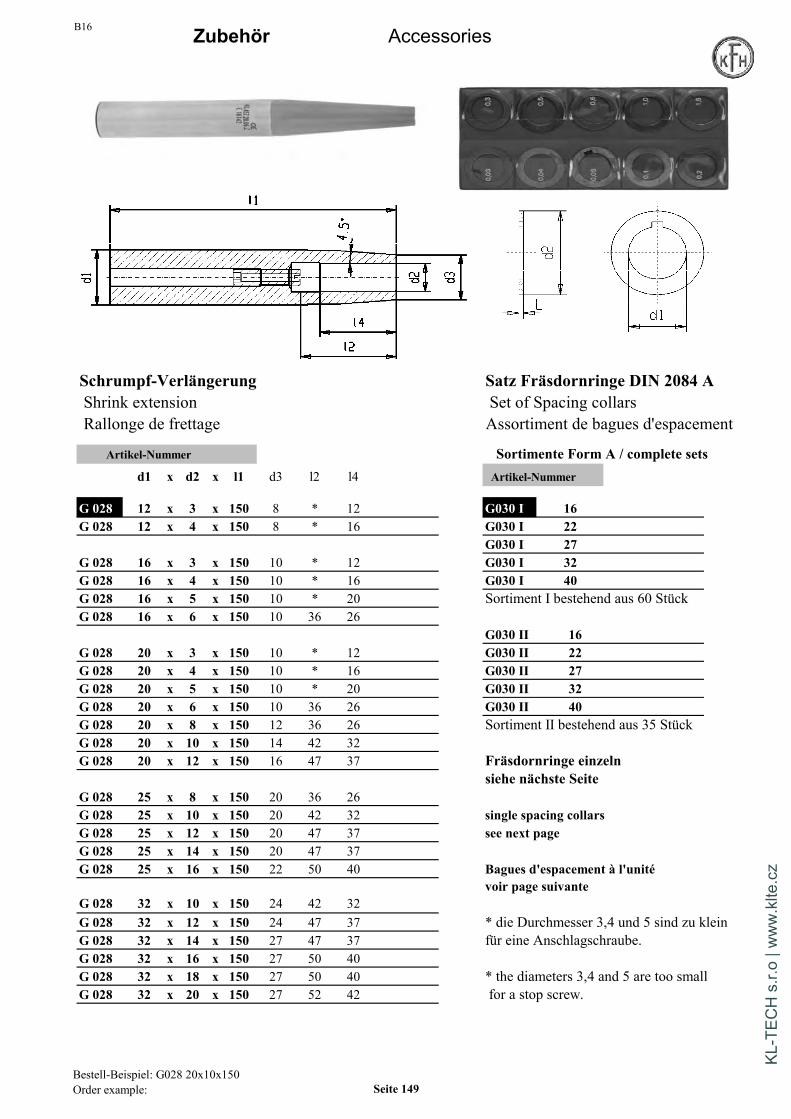
B16 Zubehör Accessories
Schrumpf-Verlängerung Satz Fräsdornringe DIN 2084 AShrink extension Set of Spacing collarsRallonge de frettage Assortiment de bagues d'espacement
Artikel-Nummer Sortimente Form A / complete setsd1 x d2 x l1 d3 l2 l4 Artikel-Nummer
G 028 12 x 3 x 150 8 * 12 G030 I 16G 028 12 x 4 x 150 8 * 16 G030 I 22
G030 I 27G 028 16 x 3 x 150 10 * 12 G030 I 32G 028 16 x 4 x 150 10 * 16 G030 I 40G 028 16 x 5 x 150 10 * 20 Sortiment I bestehend aus 60 StückG 028 16 x 6 x 150 10 36 26
G030 II 16G 028 20 x 3 x 150 10 * 12 G030 II 22G 028 20 x 4 x 150 10 * 16 G030 II 27G 028 20 x 5 x 150 10 * 20 G030 II 32G 028 20 x 6 x 150 10 36 26 G030 II 40G 028 20 x 8 x 150 12 36 26 Sortiment II bestehend aus 35 StückG 028 20 x 10 x 150 14 42 32G 028 20 x 12 x 150 16 47 37 Fräsdornringe einzeln
siehe nächste SeiteG 028 25 x 8 x 150 20 36 26G 028 25 x 10 x 150 20 42 32 single spacing collarsG 028 25 x 12 x 150 20 47 37 see next pageG 028 25 x 14 x 150 20 47 37G 028 25 x 16 x 150 22 50 40 Bagues d'espacement à l'unité
voir page suivanteG 028 32 x 10 x 150 24 42 32G 028 32 x 12 x 150 24 47 37 * die Durchmesser 3,4 und 5 sind zu kleinG 028 32 x 14 x 150 27 47 37 für eine Anschlagschraube.G 028 32 x 16 x 150 27 50 40G 028 32 x 18 x 150 27 50 40 * the diameters 3,4 and 5 are too smallG 028 32 x 20 x 150 27 52 42 for a stop screw.
Bestell-Beispiel: G028 20x10x150Order example: Seite 149
KL-T
ECH
s.r.
o | w
ww
.klte
.cz

B16Zubehör Accessories
Form Ageschnitten
Fräsdornringe DIN 2084 FormA Fräsdornringe DIN 2084 FormASpacing collars Spacing collarsBagues d'espacement Bagues d'espacementArtikel-Nummer Artikel-Nummer
d1 x L d2 d1 x L d2
G030 A 13 x 0,03 21 auf Anfrage G030 A 32 x 0,03 45 auf AnfrageG030 A 13 x 0,05 21 auf Anfrage G030 A 32 x 0,05 45 auf AnfrageG030 A 13 x 0,1 21 auf Anfrage G030 A 32 x 0,1 45 auf AnfrageG030 A 13 x 0,2 21 auf Anfrage G030 A 32 x 0,2 45 auf AnfrageG030 A 13 x 0,3 21 auf Anfrage G030 A 32 x 0,3 45 auf AnfrageG030 A 13 x 0,5 21 auf Anfrage G030 A 32 x 0,5 45 auf AnfrageG030 A 13 x 0,6 21 auf Anfrage G030 A 32 x 0,6 45 auf AnfrageG030 A 13 x 1,0 21 auf Anfrage G030 A 32 1,0 45 auf Anfrage
G030 A 16 x 0,03 25 auf Anfrage G030 A 40 x 0,03 54 auf AnfrageG030 A 16 x 0,05 25 auf Anfrage G030 A 40 x 0,05 54 auf AnfrageG030 A 16 x 0,1 25 auf Anfrage G030 A 40 x 0,1 54 auf AnfrageG030 A 16 x 0,2 25 auf Anfrage G030 A 40 x 0,2 54 auf AnfrageG030 A 16 x 0,3 25 auf Anfrage G030 A 40 x 0,3 54 auf AnfrageG030 A 16 x 0,5 25 auf Anfrage G030 A 40 x 0,5 54 auf AnfrageG030 A 16 x 0,6 25 auf Anfrage G030 A 40 x 0,6 54 auf AnfrageG030 A 16 x 1,0 25 auf Anfrage G030 A 40 x 1,0 54 auf Anfrage
G030 A 22 x 0,03 33 auf Anfrage G030 A 50 x 0,05 67 auf AnfrageG030 A 22 x 0,05 33 auf Anfrage G030 A 50 x 0,1 67 auf AnfrageG030 A 22 x 0,1 33 auf Anfrage G030 A 50 x 0,2 67 auf AnfrageG030 A 22 x 0,2 33 auf Anfrage G030 A 50 x 0,3 67 auf AnfrageG030 A 22 x 0,3 33 auf Anfrage G030 A 50 x 0,5 67 auf AnfrageG030 A 22 x 0,5 33 auf Anfrage G030 A 50 x 0,6 67 auf AnfrageG030 A 22 x 0,6 33 auf Anfrage G030 A 50 x 1,0 67 auf AnfrageG030 A 22 x 1,0 33 auf Anfrage
G030 A 60 x 0,1 83 auf AnfrageG030 A 27 x 0,03 39 auf Anfrage G030 A 60 x 0,2 83 auf AnfrageG030 A 27 x 0,05 39 auf Anfrage G030 A 60 x 0,3 83 auf AnfrageG030 A 27 x 0,1 39 auf Anfrage G030 A 60 x 0,5 83 auf AnfrageG030 A 27 x 0,2 39 auf Anfrage G030 A 60 x 0,6 83 auf AnfrageG030 A 27 x 0,3 39 auf Anfrage G030 A 60 x 1,0 83 auf AnfrageG030 A 27 x 0,5 39 auf AnfrageG030 A 27 x 0,6 39 auf Anfrage Fortsetzung Form B nächste SeiteG030 A 27 x 1,0 39 auf Anfrage
Breite 0,4 / 0,7 / 0,8 / 0,9 auf Anfrage Verpackungseinheit Form A 10 StückWidth 0,4 / 0,7 / 0,8 / 0,9 on request Packing unit Form A 10 pcsLongueur 0,4 / 0,7 / 0,8 / 0,9 sur demande Unité d'emballage forme A 10 pièces
Bestell-Beispiel: G030 A 22x0,20Order example: Seite 150
KL-T
ECH
s.r.
o | w
ww
.klte
.cz
B16 Zubehör Accessories
Form B = gedrehtund geschliffen
Form B = turnedand grinded
Forme B = tournéeet rectifiée
Fräsdornringe DIN 2084 Form B Spacing collars Bagues d'espacement
Artikel-Nummer Artikel-Nummer Artikel-Nummer
d1 x L d2 d1 x L d2 d1 x L d2
G030 B 13 x 2 22 a. Anfrage G030 B 27 x 2 41 G030 B 40 x 2 55G030 B 13 x 3 22 a. Anfrage G030 B 27 x 3 41 G030 B 40 x 3 55G030 B 13 x 4 22 a. Anfrage G030 B 27 x 4 41 G030 B 40 x 4 55G030 B 13 x 5 22 a. Anfrage G030 B 27 x 5 41 G030 B 40 x 5 55G030 B 13 x 6 22 a. Anfrage G030 B 27 x 6 41 G030 B 40 x 6 55G030 B 13 x 10 22 a. Anfrage G030 B 27 x 10 41 G030 B 40 x 10 55G030 B 13 x 20 22 a. Anfrage G030 B 27 x 41 G030 B 40 x 20 55G030 B 13 x 30 22 a. Anfrage G030 B 27 x 30 41 G030 B 40 x 30 55
G030 B 27 x 60 41 G030 B 40 x 60 55G030 B 27 x 100 41 G030 B 40 x 100 55
G030 B 16 x 2 27G030 B 16 x 3 27G030 B 16 x 4 27 G030 B 32 x 2 47 G030 B 50 x 2 69G030 B 16 x 5 27 G030 B 32 x 3 47 G030 B 50 x 3 69G030 B 16 x 6 27 G030 B 32 x 4 47 G030 B 50 x 4 69G030 B 16 x 10 27 G030 B 32 x 5 47 G030 B 50 x 5 69G030 B 16 x 20 27 G030 B 32 x 6 47 G030 B 50 x 6 69G030 B 16 x 30 27 G030 B 32 x 10 47 G030 B 50 x 10 69
G030 B 32 x 20 47 G030 B 50 x 20 69G030 B 32 x 30 47 G030 B 50 x 30 69
G030 B 22 x 2 34 G030 B 32 x 60 47 G030 B 50 x 60 69G030 B 22 x 3 34 G030 B 32 x 100 47 G030 B 50 x 100 69G030 B 22 x 4 34G030 B 22 x 5 34G030 B 22 x 6 34 G030 B 60 x 3 84 a. AnfrageG030 B 22 x 10 34 G030 B 60 x 4 84 a. AnfrageG030 B 22 x 20 34 G030 B 60 x 5 84 a. AnfrageG030 B 22 x 30 34 G030 B 60 x 6 84 a. AnfrageG030 B 22 x 60 34 G030 B 60 x 10 84 a. AnfrageG030 B 22 x 100 34 G030 B 60 x 20 84 a. Anfrage
G030 B 60 x 30 84 a. AnfrageG030 B 60 x 60 84 a. Anfrage
Gehärtet: Vickershärte min. 550 HV (min. 52 HRC), G030 B 60 x 100 84 a. Anfragezulässige Abweichung der Parallelität für die Breite L beträgt IT3 bezogen auf Bohrung d1.
alloyed case-hardened steel. Carbonized according to Vickers min. 550 HV (min. 52 HRC)
Trempées: dureté Vickers mini. 550 HV (mini. 52 HRC),Le défaut de parallélisme admissible pour la largeur L est de IT3 par rapport au perçage d1.
Bestell-Beispiel: G030 B 22x10Order example: Seite 151
KL-T
ECH
s.r.
o | w
ww
.klte
.cz

B16Zubehör Accessories
Laufbuchsen DIN 2083 Muttern ähnlich DIN 2082 für lange FräserdorneBearing collars DIN 2083 Nuts for long milling arbors similar DIN 2082Douille de glissement DIN 2083 Ecrou similaire DIN 2082
Artikel-Nummer Artikel-Nummer
d1 x d2 x L d1=Gewinde d2 L S
G 035 16 x 42 x 60 G034 13 M12x1,5 22 14 19G 035 16 x 48 x 70 G034 16 M16x1,5 26 16 22G 035 16 x 56 x 80 G034 22 M20x1,5 34 22 27
G034 27 M24x1,5 40 28 32G 035 22 x 42 x 60 G034 32 M30x1,5 47 32 41G 035 22 x 48 x 70 G034 40 M36x2 55 40 46G 035 22 x 56 x 80 G034 50 M42x2 68 46 55 AnfrageG 035 22 x 70 x 100 G034 60 M52x2 80 56 65 Anfrage
G 035 27 x 42 x 60G 035 27 x 48 x 70G 035 27 x 56 x 80G 035 27 x 70 x 100G 035 27 x 85 x 120
G 035 32 x 48 x 70G 035 32 x 56 x 80G 035 32 x 70 x 100G 035 32 x 85 x 120
G 035 40 x 56 x 80G 035 40 x 70 x 100G 035 40 x 85 x 120
G 035 50 x 70 x 100G 035 50 x 85 x 120G 035 50 x 110 x 140
G 035 60 x 110 x 140 Anfrage
Bestell-Beispiel: G035 27x48x70Order example: Seite 152
KL-T
ECH
s.r.
o | w
ww
.klte
.cz

B16 Zubehör Accessories
Holzsockel für SpannzangenWooden socket for colletsSocle bois pour pinces de serrageArtikel-Nummer
LochzahlG027 ER16 10G027 ER25 18
Koffer für Spannzangenfutter / G027 ER32 18Spannzangen und Schlüssel G027 ER40 24Plastic case for collet chuck G027 ER50 12 Anfrage
collets and wrench G027 Holzkasten ER25 14
Valise pour mandrins à pince / G027 OZ16 415 15
pinces et clé G027 30
Artikel-Nummer
G026 Koffer SK30/SK40G026 Koffer SK50
Aufsteck-BohrfutterkopfDrill-chuck-headTete de mandrin de percage
2D Kantentaster elektr.2D Edge-finderTouche de palpage 2D
D L d1G047 2D 20 95 10G047 2D16 16 99 10
3D Kantentaster elektr.3D Edge-finder
Artikel-Nummer Touche de palpage 3Dd1 L D D L d1
G047 3D20 20 106 10BK Re13G30B16 1-13 91 51 G047 3D16 16 111 10BK Re16G30B16 3-16 96 57
Bestell-Beispiel: G027 ER32Order example: Seite 153
KL-T
ECH
s.r.
o | w
ww
.klte
.cz

B16Zubehör Accessories
Mitnehmerringe DIN 6366 für Kombidorne Schlüssel DIN 6368 für Fräseranzugsschr.Drive rings DIN 6366 Wrenches DIN 6368Bague d'entrainement Clé de serrage DIN 6368
Artikel-Nummer Artikel-Nummer
d1 d2 a D L H
G 040 13 28 10 G 042 13 16G 040 16 32 10 G 042 16 180 20G 040 22 40 12 G 042 22 200 25G 040 27 48 12 G 042 27 225 32G 040 32 58 14 G 042 32 250 36G 040 40 70 14 G 042 40 280 40G 040 50 90 16 G 042 50 315 45G 040 60 110 16 auf Anfrage G 042 60 355 50 auf Anfrage
Fräseranzugsschraube DIN6367 Rollenschlüssel für KraftspannfutterClamping screws DIN 6367 Wrench for High Power milling chuckVis de blocage Cle pour mandrin a fort serrageArtikel-Nummer
Drm. g d2 k l1G 041 13 M6 17 5 12G 041 16 M8 20 6 16G 041 22 M10 28 7 18G 041 27 M12 35 8 22 Artikel-Nummer Innen InnerG 041 32 M16 42 9 26 Drm DiaG 041 40 M20 52 10 30 G017 KSF 20 48 48G 041 50 M24 63 12 36 G017 KSF 32 68 68G 041 60 M30 75 14 45 Anfrage
Bestell-Beispiel: G040 32Order example: Seite 154
KL-T
ECH
s.r.
o | w
ww
.klte
.cz
B16Zubehör Accessories
Verlängerungen f. Messerkopfaufnahmen Verlängerungen für AufschraubfräserFace mill extensions Extensions for chuck for threaded type cutterRallonges pour porte-fraises à tenon Rallonges mandrin porte-fraises à queue fileteeArtikel-Nummer Artikel-Nummer
d2 x L D M x M1 D L
G043V 16 x 30 38 G047V M8 x M8 13,5 30G043V 16 x 100 38 G047V M10 x M10 18,5 35
G047V M12 x M12 23 40G043V 22 x 30 48 G047V M16 x M16 30 40G043V 22 x 100 48
G043V 27 x 35 58 Reduzierungen für AufschraubfräserG043V 27 x 100 58 Reductions for chuck for threaded type cutter
Réductions mandrin porte-fraises à queue fileteeG043V 32 x 40 64G043V 32 x 100 64 Artikel-Nummer
M x M1 D LG043V 40 x 50 80G043V 40 x 120 80 G047R M8 x M5 13 30
G047R M10 x M8 18,5 30Zur Verlängerung von Messerkopfaufnahmen G047R M12 x M10 23 35incl. zugehöriger Schraube G047R M16 x M10 30 60
G047R M16 x M12 30 60For extension of face-mill-holdersincl. corresponding screw
Pour extension de porte fraises a tenonavec vis de serrage
Bestell-Beispiel: G043V 22x100Order example: Seite 155
KL-T
ECH
s.r.
o | w
ww
.klte
.cz
B16Zubehör Accessories
Montage-Vorrichtung KegelwischerAssembly device Spindle wiperBloc de montage en acier Essuie-côneArtikel-Nummer Artikel-Nummer
LG049 30 G048 MK 1 160G049 30 Alu G048 MK 2G049 40 G048 MK 3 185G049 45 G048 MK 4 220G049 50 G048 MK 5 250G649 HSK63 Schwenk
G048 SK 30 150Zum Spannen von Schneidwerkzeugen und Anzugsbolzen. G048 SK 40 180Es kann wahlweise vertikal oder horizontal gearbeitet werden. G048 SK 45 190
G048 SK 50 220For clamping and un-clamping of toolings or pull-studs.It can be used either vertical or horizontical G048 HSK 32 142
G048 HSK 40 142Pour le serrage d'outils de coupe et de tirettes. G048 HSK 50 152Pour utilisation verticale ou horizontale. G048 HSK 63 168
G048 HSK 80 178G048 HSK 100 199
Grundkörper aus schlagfestem Kunsstoff mit Vliesbelag inNuten eingesetzt und somit gegen Verdrehen geschützt.
Sturdy plastic with inserted artificial leather
Corps de base en plastique anti-choc revêtu de feutrinelogée dans des rainures afin d'éviter tout vrillage.
Bestell-Beispiel: G048 40 Seite 156
KL-T
ECH
s.r.
o | w
ww
.klte
.cz
B16 Anzugsbolzen Pull Studs Tirettes
Anzugsbolzen DIN 69872 Standard Anzugsbolzen ISO 7388 Typ BPull Studs DIN 69872 Pull Studs ISO 7388 Typ BTirettes DIN 69872 Tirettes ISO 7388 Typ BArtikel-Nummer Artikel-Nummer
SK Bohr. d1 l2 l1 g SK Bohr. l1 l2 d1 gG050 30 mit 13 24 44 M12 G051 40 mit 45 16,3 19 M16G050 40 mit 19 26 54 M16 G051 50 mit 66 25,5 29 M24G050 50 mit 28 34 74 M24 G051 40 ohne 45 16,3 19 M16G050 30 ohne 13 24 44 M12 G051 50 ohne 66 25,5 29 M24G050 40 ohne 19 26 54 M16G050 50 ohne 28 34 74 M24
mit = with bore / avecohne = without bore / sans
Sonderausführung SK40 z.B. für Nikken Sonderausführung SK40 z.B. für Mazak CATKitamura / JIS B 6339 l2 = 3mm länger
Artikel-Nr. SK Bohr. d1 l2 l1 g Artikel-Nr. SK Bohr. l1 l2 d1 g
G050 mit 40 L 40 mit 19 29 54 M16 G051m mit 40 40 mit 41,2 16,25 19 M16G050 ohne 40 L 40 ohne 19 29 54 M16
Sonderausführung SK50 Sonderausführung SK40 z.B. für Fadall2 = 25mm länger
Artikel-Nr. SK Bohr. d1 l2 l1 g Artikel-Nr. SK Bohr. l1 l2 d1 g
G050 mit 50 L 50 mit 28 59 99 M24 G051m mit 40/lg 40 mit 44,1 19,1 19 M16
Max. zulässiges Anzugsmoment SK30 = 25 NmMax. permissible torque SK40 = 50 NmCouple de serrage autorise max. SK50 = 150 Nm
Bestell-Beispiel: G050 40 mitOrder example: Seite 157
KL-T
ECH
s.r.
o | w
ww
.klte
.cz

B16Anzugsbolzen Pull Studs Tirettes
Anzugsbolzen DIN 69872 lang Anzugsbolzen ISO 7388 Typ B langPull Studs DIN 69872 long Pull Studs ISO 7388 Typ B longTirettes DIN 69872 longues Tirettes ISO 7388 Typ B longues
Artikel-Nummer Artikel-NummerSK Bohr. f.MK d1 l2 l1 SK Bohr. f.MK d1 l2 l1
G050XL 30 mit 2 13 24 90 Auf Anfrage # G051XL 40 mit 4 19 16,4 105 Auf Anfrage #G050XL 30 mit 2 13 24 130 Auf Anfrage # G051XL mit 3 29 25,5 137 Auf Anfrage #G050XL 30 mit 3 13 24 99 Auf Anfrage # G051XL 50 mit 4 29 25,5 126 Auf Anfrage #G050XL 40 mit 4 19 26 115 Auf Anfrage # G051XL 50 mit 5 29 25,5 146 Auf Anfrage #G050XL 50 mit 5 28 34 154 Auf Anfrage # G051XL 40 ohne 2 19 16,4 91 Auf AnfrageG050XL 30 ohne 1 13 24 84 Auf Anfrage G051XL 40 ohne 3 19 16,4 96 Auf AnfrageG050XL 30 ohne 1 13 24 134 Auf Anfrage G051XL 40 ohne 4 19 16,4 105 Auf AnfrageG050XL 40 ohne 3 19 26 105 Auf Anfrage G051XL 50 ohne 5 29 25,5 146 Auf AnfrageG050XL 40 ohne 4 19 26 115 Auf AnfrageG050XL 50 ohne 2 28 34 155 Auf AnfrageG050XL 50 ohne 3 28 34 145 Auf AnfrageG050XL 50 ohne 4 28 34 135 Auf AnfrageG050XL 50 ohne 5 28 34 154 Auf Anfrage
Gewinde : MK1 M6Thread MK2 M10
# Lagerabverkauf - keine Neuauflage mehr Filetage MK3 M12obsolete article with rest stock levels MK4 M16Liquidation du stock - ne sera plus produit MK5 M20
Verwendung um Einsatzhülsen G360 im Standard-A-Maß ( normal mit Austreiblappen )als Fräserhülsen ( mit Anzugsgewinde) nutzen zu können
For the usage of morse taper adaptors G360 ( normally for flat tang) as morese taper adaptorswith draw thread.
Pour pouvoir utiliser les douilles G360 dans la cote standard A ( normale avec tenon d'extraction )en tant que douilles à fraises ( avec filetage de serrage)
Max. zulässiges Anzugsmoment SK30 = 25 NmMax. permissible torque SK40 = 50 NmCouple de serrage autorise max. SK50 = 150 Nm
Bestell-Beispiel: G050XL40mit4 Seite 158
KL-T
ECH
s.r.
o | w
ww
.klte
.cz

B16 Anzugsbolzen Pull Studs Tirettes
Anzugsbolzen MAS-BT Anzugsbolzen MAS BT langPull Studs MAS BT Pull Studs MAS BT longTirettes MAS BT Tirettes MAS BT longues
Artikel-Nummer Artikel-Nummer
BT Grad Bohr. l1 l2 g BT Grad Bohr. l1 l2 gG055 30 45° ohne 43 23 M12 G055XL 30 60° ohne MK1 78 23 M6 Auf AnfrageG055 40 45° ohne 60 35 M16 G055XL 30 60° ohne MK2 88 23 M10 Auf AnfrageG055 50 45° ohne 85 45 M24 G055XL 30 60° ohne MK3 90 23 M12 Auf Anfrage
G055 30 60° ohne 43 23 M12 G055XL 35 ohne MK1 99 28 M6 Auf AnfrageG055 35 60° ohne 53 28 M12 G055XL 35 60° ohne MK2 99 28 M10 Auf AnfrageG055 40 60° ohne 60 35 M16 G055XL 35 60° ohne MK3 99 28 M12 Auf AnfrageG055 50 60° ohne 85 45 M24
G055XL 40 45° ohne MK2 105 35 M10 Auf AnfrageG055 40 90° ohne 60 35 M16 G055XL 40 45° ohne MK3 115 35 M12 Auf AnfrageG055 50 90° ohne 85 45 M24 G055XL 40 45° ohne MK4 120 35 M16 Auf Anfrage
G055XL 40 60° ohne MK2 105 35 M10 Auf Anfrageohne = without bore / sans forage G055XL 40 60° ohne MK3 115 35 M12 Auf Anfrage
G055XL 40 60° ohne MK4 120 35 M16 Auf AnfrageG055m 30 45° mit 43 23 M12 G055XL 40 90° ohne MK2 105 35 M10 Auf AnfrageG055m 40 45° mit 60 35 M16 G055XL 40 90° ohne MK3 115 35 M12 Auf AnfrageG055m 50 45° mit 85 45 M24 G055XL 40 90° ohne MK4 120 35 M16 Auf Anfrage
G055m 30 60° mit 43 23 M12 G055XL 50 45° ohne MK5 160 45 M20 Auf AnfrageG055m 40 60° mit 60 35 M16 G055XL 50 60° ohne MK5 160 45 M20 Auf AnfrageG055m 50 60° mit 85 45 M24 G055XL 50 90° ohne MK5 160 45 M20 Auf Anfrage
G055m 40 90° mit 60 35 M16G055m 50 90° mit 85 45 M24 Max. zulässiges Anzugsmoment BT30 = 25 Nm
Max. permissible torque BT40 = 50 Nmmit = with bore / avec perçage Couple de serrage autorise max. BT50 = 150 Nm
Bestell-Beispiel: G055 40 60° ohneOrder example: Seite 159
KL-T
ECH
s.r.
o | w
ww
.klte
.cz

B16Anzugsbolzen Pull Studs Tirettes
Einschraubbare Mitnehmerlappen Anzugsbolzen mit SägegewindeTangs to screw in Pull stud with thread S20x2Languettes d'expulsion Tirette avec filetage S20x2Artikel-Nummer Artikel-Nummer
für GewindeG052 MK1 M6 G057 S20x2 M16G052 MK2 M10G052 MK3 M12G052 MK4 M16G052 MK5 M20
Kühlmittelrohr HSKCoolant tube / Tube de refroidissementArtikel-Nummer
G065 63G065 100
Ringnut-Bolzen m. Innengew.Pull studs for use as DIN2080Tirette pour usage DIN 2080Artikel-Nummer Montageschlüssel für Kühlmittelrohr HSK
SK g l1 l2 Wrench for assembling Coolant tube HSKG056 40 M16 53 25 Clé de montage tube de refroidissement HSKG056 50 M24 65 25,5 Artikel-Nummer
Max. zulässiges Anzugsm. SK40 = 50 Nm G065s 63Max. permissible torque SK50 = 150 Nm G065s 100
Bestell-Beispiel: G065 A63 Seite 160
KL-T
ECH
s.r.
o | w
ww
.klte
.cz

B16 Anzugsbolzen Pull Studs Tirettes
Sonderbolzen SK40 Hurco/Bridgeport Sonderbolzen Kelch / StamaSpecial pull stud SK40 Hurco/Bridgeport Special pull stud Kelch / StamaTirettes spéciales ISO40 Hurco/Bridgeport Tirettes spéciales Kelch / Stama
Artikel-Nummer Artikel-Nummerd1 Bohr. l1 l2 b SK Gewinde d1 l1 l2
G058 Hurco 15 ohne 57,1 32 6 G058 Kelch 40 M16 14 50 25G058 Hurco Brid 15 ohne 60,0 32 3 G058 Kelch 50 M24 14 60 25G058 Hurco mB 15 mit 57,1 32 6G058 Hurco mbBr 15 mit 60,0 32 3 G058 Stama 30 M12 11 43,6 23,6
Hermle 3 für DIN69871 Hermle 1 für DIN2080
Sonderbolzen SK40 HermleSpecial pull stud SK40 Hermle Max. zulässiges Anzugsmoment M16 = 50 NmTirettes spéciales ISO40 Hermle Max. permissible torque M24 = 150 Nm
Artikel-Nummerd1 g l1 l2
G058 Hermle 1 14 M16 47 27 für DIN 2080G058 Hermle 3 14 M16 80 52 für DIN 69871
Bestell-Beispiel: G058 Hurco mBOrder example: Seite 161
KL-T
ECH
s.r.
o | w
ww
.klte
.cz

B16Schraubstöcke Vices Etaux
Bohrmaschinen-Schraubstock MSPDrilling machine vice MSP Körper aus Guss / Stahlbacken mit vertikalemEtau pour perceuses MSP und horizontalem Prisma
Cast iron body Corps en fonte / mors acier avecSteel jaws with vertical and horizontal prism prisme vertical et horizontal
Artikel-Nummer Backenbreite mm Spannweite mm Backenhöhe mm Gewicht kgJaw width max jaw opening Jaw height Weight
SCHMSP 85 85 70 28 3,8SCHMSP 100 100 90 28 4,4SCHMSP 120 120 110 35 7,2
Hydraulischer Maschinen-SchraubstockHydraulic machine viceEtau machines hydrauliquemit Kurbel / with crank / avec manivelle
Artikel-Nummer Spannkraft GewichtA B C a b c d e f g h Clamp-force weightmm mm mm mm mm mm mm mm mm mm mm daN kg
SCH FHS 100 35 170 525 435 110 160 94 58 60 155 2500 18SCH FHS 125 45 220 670 540 165 185 116 72 97 117 4000 32SCH FHS 150 51 300 800 610 165 240 133 82 125 150 5000 51SCH FHS 200 62 300 900 700 225 280 160 100 200 265 7000 90
Robuste Bauart mit mechanisch-hydraulischer Hochdruckspindel, grosse Spannweite, hohe Spanngenauigkeit, Schnellverstellung durch Steckbolzen, alleVerschleißteile gehärtet, deshalb verwendbar sowohl für schwere als auch leichte Zerspanung.
Sturdy design with hydraulic high-presure spindle, mechanical drive, large clamping capacity, high accuracy, rapid clamping range adjustment with 1 socket pin, allwearing parts hardened, therefore suitable for heavy and light-duty machining operations.
Construction robuste avec broche haute pression mécanique/hydraulique, grande capacité de serrage, précision de serrage élevée, réglage rapide par boulon enfichable,toutes pièces d'usure trempées, donc utilisable pour l'usinage lourd et léger.
Bestell-Beisp.: SCH FHS 125Order example: Seite 162
KL-T
ECH
s.r.
o | w
ww
.klte
.cz

B16 Schraubstöcke Vices Etaux
Maschinen-Schraubstock, mechanischMachine vice, mechanicalEtau machines mécaniquemit Kurbel / with crank / avec manivelle
A B Cmax E E1 F G H L M Max Spannkraft GewichtArtikel-Nummer mm mm mm mm mm mm mm mm mm mm Clamping force weight
Force de serrage maxi. Poids
SCHMSK 100 104 36 62 293 310 13 145 83 15 65 900 9 kgSCHMSK 125 130 37 82 362 384 13 172 15 84 900 15 kgSCHMSK 150 152 43 112 442 473 15 209 108 17 90 1000 26 kgSCHMSK 200 204 63 149 579 609 18 312 148 21 122 1400 53 kg
Maschinen-Schraubstock m. DrehplatteMachine vice with swivel plateEtau machine avec socle tournantmit Kurbel / with crankWie Typ MSK, aber mit Drehplatte / as type MSK, but with swivel base / comme type MSK mais avec socle tournant
Max Spannkraft Gewicht
A B Cmax D E E1 F G H I J K L M Clamping force weight
Artikel-Nummer mm mm mm mm mm mm mm mm mm mm mm mm mm mm Force de serrage m Poids
SCHMSK 100D 104 36 62 76 293 310 13 145 83 113 176 122 15 65 900 10 kg
SCHMSK 125D 130 37 82 92 362 384 13 172 97 129 209 147 15 84 900 17 kgSCHMSK 150D 152 43 112 105 442 473 15 209 108 148 260 181 17 90 1000 28 kgSCHMSK 200D 204 63 149 127 579 609 18 312 148 190 350 234 21 122 1400 56 kg
Für Fräs-, Hobel- und Bohrarbeiten, grosser Verstellbereich, hohe Kraftübertragung. Mit gehärteten und geschliffenen Backen.For milling and drilling operations. Material: special cast iron Large clamping capacity, with hardened and ground jaws.Pour travaux de fraisage, rabotage et perçage, grande capacité de réglage, transmission de force élevée,avec mors trempés et rectifié
Bestell-Beisp.: SCH MSK 100Order example: Seite 163
KL-T
ECH
s.r.
o | w
ww
.klte
.cz

B16Schraubstöcke Vices Etaux
Präzisions-Hochdruckspanner mit mechanischer KraftverstärkungHigh-power vice with mechanical force increaseEtau de précision haute pression, avec renforçage mécanique de la force
M A B C D Emax F G H I J K L N Spannkraft GewichtArtikel-Nummer mm mm mm mm mm mm mm mm mm mm mm mm mm Clamp-force weight
SCHMC2 125 365 145 78 74 208 45 18 100 145 98,5 126 464 135 500-4500 daN 35 kgSCHMC2 160 455 160 86 86 275 45 18 115 145 98,5 162 554 171 500-5400 daN 57 kgSCHMC2 200 505 180 100 97 300 55 18 125 177 100 202 604 211 500-6800 daN 90 kg
Stahlkörper allseitig geschliffen und aufspannbar / Anti-Lift-Mechanismus / Eingebauter Niederzug / Kurze Bauart/ Mechanische KraftverstärkunDichtungslos und wartungsfrei / Kurze Bauart / Spannkraft voreinstellbar / incl. 4 Spannpratzen, Hebeösen, Schlüssel u. Nutensteine
Steel body, all surfaces ground / Three clamping positions: horizontal, vertical, lateral / With "anti-lifting" mechanism / Mechanical force increase
no seals required, maintenance free / Short body / Pre-selection of clamping force / Incl. clamping brackets, hoisting lugs, keys and T-nuts
Corps acier rectifiés de tous côtés et serrable / mécanisme anti-levée / pression vers le bas intégrée / version courte / renforçage mécanique
de la force / sans joints ni maintenance / force de serrage pré-réglabley / compris 4 griffes de serrage, oeillets de levée, clés et tasseaux en T
Präzisions-MaschinenschraubstockHigh-precision machine viceEtau de précision
W A L B N C D H I Spannkraft Gewicht
Artikel-Nummer mm mm mm mm mm mm mm mm mm Clamp-force weight
SCH CMC 100-1 100 100 270 320 30 75 77,9 35 16 3000 daN 7 kgSCH CMC 125-1 125 150 345 410 40 95 77,9 40 16 3000 daN 13 kgSCH CMC 150-1 150 200 420 500 50 125 89,4 50 16 5000 daN 26 kgSCH CMC 150-2 150 300 520 600 50 125 89,4 50 16 5000 daN 29 kgSCH CMC 200-1 200 200 495 580 65 170 113 70 16 10000 daN 64 kgSCH CMC 200-2 200 300 595 680 65 170 113 70 16 10000 daN 69 kgSCH CMC 200-3 200 400 695 780 65 170 113 70 16 10000 daN 74 kg
Führungsflächen gehärtet / mit Niederzugeffekt / modulares System / Parallelität < 0,005/100 mm / Rechtwinkligkeit < 0,02/50 mm
Wiederholgenauigkeit < 0,02 mm / incl. Spannpratzen, Passsteine, Schlüssel, Handkurbel und Werkstückanschlag
hardened slide ways / with pull-down mechanism / modular system / parallelism < 0,005/100 mm /perpendicularity < 0,02/50 mm
repeatability < 0,02 mm / incl. brackets, keynuts, wrench, crank and workpiece stop
Surfaces de guidage trempées / avec effet de pression vers le bas / système modulaire / parallélisme <0,005/100 mm
perpendicularité <0,02/50 mm / répétabilité < 0,02 my / compris griffes de serrage, tasseaux, clé, manivelle et butée
Bestell-Beisp.: SCH CMC 100-1Order example: Seite 164
KL-T
ECH
s.r.
o | w
ww
.klte
.cz
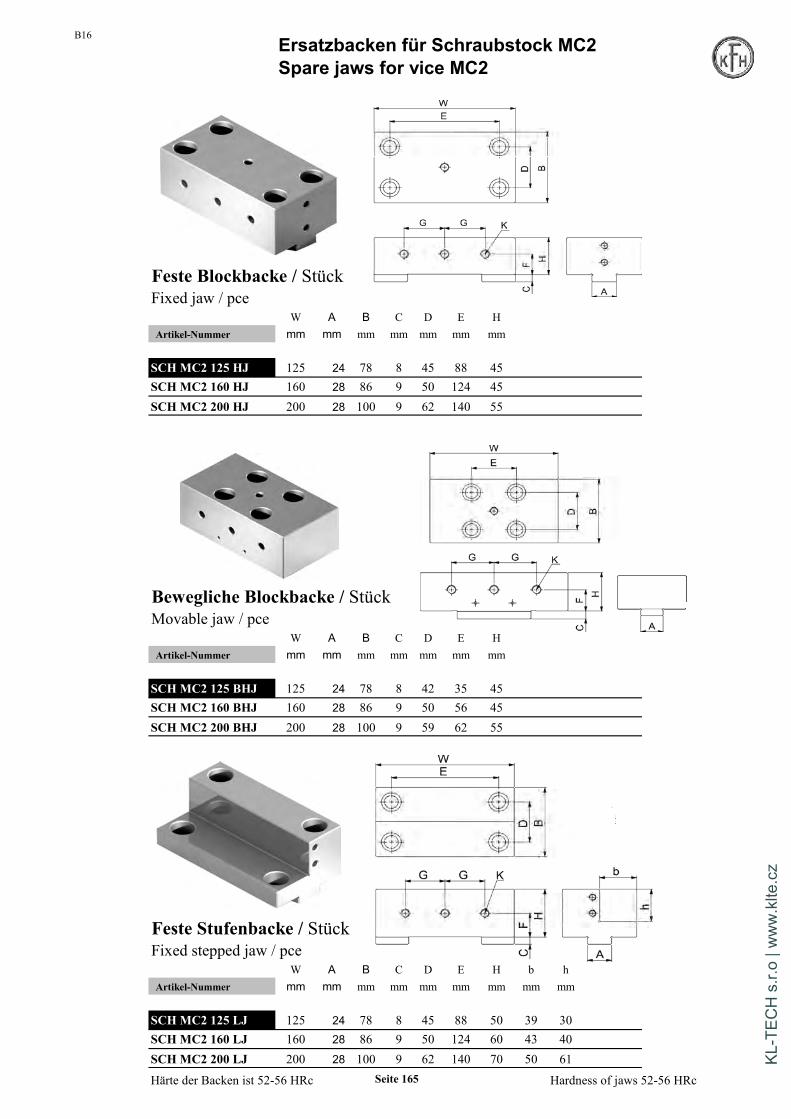
B16 Ersatzbacken für Schraubstock MC2Spare jaws for vice MC2
Feste Blockbacke / StückFixed jaw / pce
W A B C D E HArtikel-Nummer mm mm mm mm mm mm mm
SCHMC2 125 HJ 125 24 78 8 45 88 45SCHMC2 160 HJ 160 28 86 9 50 124 45SCHMC2 200 HJ 200 28 100 9 62 140 55
Bewegliche Blockbacke / StückMovable jaw / pce
W A B C D E HArtikel-Nummer mm mm mm mm mm mm mm
SCHMC2 125 BHJ 125 24 78 8 42 35 45SCHMC2 160 BHJ 160 28 86 9 50 56 45SCHMC2 200 BHJ 200 28 100 9 59 62 55
Feste Stufenbacke / StückFixed stepped jaw / pce
W A B C D E H b hArtikel-Nummer mm mm mm mm mm mm mm mm mm
SCHMC2 125 LJ 125 24 78 8 45 88 50 39 30SCHMC2 160 LJ 160 28 86 9 50 124 60 43 40SCHMC2 200 LJ 200 28 100 9 62 140 70 50 61
Härte der Backen ist 52-56 HRc Hardness of jaws 52-56 HRcSeite 165
KL-T
ECH
s.r.
o | w
ww
.klte
.cz

B16Ersatzbacken für Schraubstock MC2Spare jaws for vice MC2
Bewegliche Stufenbacke / StückMovable stepped jaw / pce
W A B C D E H b hArtikel-Nummer mm mm mm mm mm mm mm mm mm
SCHMC2 125 BLJ 125 24 78 8 42 35 50 39 30SCHMC2 160 BLJ 160 28 86 9 50 56 60 43 40SCHMC2 200 BLJ 200 28 100 9 59 62 70 50 61
Prismenbacke / StückPrism jaw / pce
A B C D E FArtikel-Nummer mm mm mm mm mm mm
SCHMC2 125 SVJ 125 47 25 30 25 64 M8SCHMC2 160 SVJ 160 62 30 30 30 92 M10SCHMC2 200 SVJ 200 72 30 30 30 100 M10
Koordinaten-Prismenbacke / StückV-jaw / pce
A B C D EArtikel-Nummer mm mm mm mm mm
SCHMC2 125 LVJ 125 47 50 110 64 M8SCHMC2 160 LVJ 160 62 55 130 92 M10SCHMC2 200 LVJ 200 72 55 130 100 M10
Härte der Backen ist 52-56 HRc Hardness of jaws 52-56 HRcSeite 166
B16Ersatzbacken für Schraubstock MC2Spare jaws for vice MC2
Bewegliche Stufenbacke / StückMovable stepped jaw / pce
W A B C D E H b hArtikel-Nummer mm mm mm mm mm mm mm mm mm € / St.
SCH MC2 125 BLJ 125 24 78 8 42 35 50 39 30 275,00SCH MC2 160 BLJ 160 28 86 9 50 56 60 43 40 275,00SCH MC2 200 BLJ 200 28 100 9 59 62 70 50 61 315,00
Prismenbacke / StückPrism jaw / pce
A B C D E FArtikel-Nummer mm mm mm mm mm mm € / St.
SCH MC2 125 SVJ 125 47 25 30 25 64 M8 208,00SCH MC2 160 SVJ 160 62 30 30 30 92 M10 230,00SCH MC2 200 SVJ 200 72 30 30 30 100 M10 285,00
Koordinaten-Prismenbacke / StückV-jaw / pce
A B C D EArtikel-Nummer mm mm mm mm mm € / St.
SCH MC2 125 LVJ 125 47 50 110 64 M8 245,00SCH MC2 160 LVJ 160 62 55 130 92 M10 279,00SCH MC2 200 LVJ 200 72 55 130 100 M10 295,00
Härte der Backen ist 52-56 HRc Hardness of jaws 52-56 HRcSeite 166
KL-T
ECH
s.r.
o | w
ww
.klte
.cz

B16
Liefer- und Zahlungsbedingungen
§ 1 Geltung der BedingungenDie nachstehenden Allgemeinen Geschäftsbedingungen sind ausschließlich zurVerwendung im unternehmerischen Geschäftsverkehr bestimmt.Die Lieferungen, Leistungen und Angebote der Karl Hermann GmbH erfolgenausschließlich aufgrund dieser Geschäftsbedingungen. Gegenbestätigungen desBestellers unter Hinweis auf seine Geschäfts - bzw. Einkaufsbedingungen wirdhiermit widersprochen.
§ 2 Angebote und Vertragsabschluss1. In Prospekten, Anzeigen usw. enthaltene Angebote sind – auch bezüglich derPreisangaben – freibleibend und unverbindlich. An speziell ausgearbeiteteAngebote hält sich die Karl Hermann GmbH 30 Kalendertage ab dem Datum desAngebotes gebunden.2. Nebenreden, Änderungen, Ergänzungen und/oder sonstige Abweichungen vonden vorliegenden Geschäftsbedingungen sind nur gültig, wenn die Karl HermannGmbH insoweit ihr Einverständnis erklärt hat. Das Schriftformerfordernis entfälltbei nachträglichen Nebenabreden, Änderungen und Ergänzungen des Auftrages.3. Angaben in Angeboten und/oder Auftragsbestätigungen der Karl HermannGmbH, die auf einem offensichtlichen Irrtum beruhen, namentlich einem Schreib-oder Rechenfehler, verpflichten die Karl Hermann GmbH nicht. Vielmehr gilt dieoffensichtlich gewollte Erklärung.4. Die Angebotsunterlagen, Zeichnungen, Beschreibungen, Muster undKostenvoranschläge der Karl Hermann GmbH dürfen ohne deren Genehmigungweder weitergegeben, veröffentlicht, vervielfältigt noch sonst wie Drittenzugänglich gemacht werden. Auf Verlangen sind die Unterlagen ohneZurückhaltung von Kopien zurückzugeben.5. Bei Lieferung von Sonderwerkzeugen darf die Bestellmenge um ca. 10%,mindestens jedoch um 2 St. überschritten werden.
§ 3 Preise, Preisänderungen1. Zu den Preisen kommt die Mehrwertsteuer in der jeweiligen gesetzlichenHöhe hinzu.2. Die Preise verstehen sich ohne die Kosten für Verpackung und Fracht.3. Soweit zwischen Vertragsabschluß und vereinbartem und/oder tatsächlichemLieferdatum mehr als sechs Monate liegen, gelten die zur Zeit der Lieferung oderder Bereitstellung gültigen Preise der Karl Hermann GmbH.Bei Preiserhöhungen seiner Vorlieferanten, Steigerungen von Lohn- undTransportkosten oder sonstigen unerwarteten Kostensteigerungen ist die KarlHermann GmbH berechtigt, Verhandlungen über eine Neufestsetzungdes Preises zu verlangen.4. Für Rücksendungen deren Grund der Besteller zu vertreten hat ( z.B.Falschbestellung ) berechnen wir einen Versandkostenanteil von 10% desWarenwerts, mindestens jedoch 5,00 €.
§ 4 Lieferzeiten1. Lieferfristen gelten vorbehaltlich richtiger und rechtzeitiger Selbstbelieferung,es sei denn, eine verbindliche Lieferfrist wurde schriftlich zugesagt.Zeichnet sich eine Verzögerung der Lieferung ab, teilt dies die Karl HermannGmbH unverzüglich nach Kenntniserlangung mit.2. Verzögert sich die Lieferung oder Leistung auf Grund eines Umstandes, dendie Karl Hermann GmbH, seine gesetzlichen Vertreter oder Erfüllungsgehilfen zuvertreten haben, erfolgt die Haftung nach den gesetzlichen Bestimmungen.Bei leichter Fahrlässigkeit ist die Haftung auf den vorhersehbarenvertragstypischen Schaden begrenzt.Dieser Grundsatz gilt insbesondere bei höherer Gewalt, Streik, Aussperrung,behördlichen Anordnungen usw., auch wenn diese Hindernisse bei Lieferanten derKarl Hermann GmbH oder deren Unterlieferanten eintreten.
Die Dauer einer vom Besteller im Falle der Leistungsverzögerung nach dengesetzlichen Vorschriften zu setzenden Nachfrist wird auf vier Wochenfestgelegt, die mit Eingang der Nachfristsetzung bei der Karl Hermann GmbHbeginnt. Nach Verstreichen dieser Nachfrist hat der Besteller das Recht vomVertrag zurückzutreten. Andere Ansprüche des Bestellers, sofern sie nichtschriftlich festgelegt wurden, sind ausgeschlossen.3. Die Karl Hermann GmbH kann, soweit es nicht ausdrücklich andersvereinbart ist, Teillieferungen aus einem Auftragsvolumentätigen. Die Transportkosten trägt der Kunde.
§ 5 Versand und Gefahrübergang. Die Gefahr geht auf den Besteller über, sobald die Sendung an die denTransport ausführende Person übergeben worden ist oder zwecks Versendungdas Werk der Karl Hermann GmbH verlassen hat. Wird der Versand aufVeranlassung des Bestellers verzögert oder nicht ausgeführt, geht die Gefahrmit der Meldung der Versandbereitschaft auf ihn über.2. Auf Wunsch des Bestellers werden Lieferungen in seinem Namen und aufseine Rechnung versichert.
§ 6 Mängelansprüche1. Ist die von der Karl Hermann GmbH erbrachte Leistung bzw. derLiefergegenstand mangelhaft, darf die Karl Hermann GmbH nach ihrer WahlErsatz liefern oder den Mangel beseitigen. Mehrfache Nachbesserungen - inder Regel zwei - sind innerhalb einer angemessenen Frist zulässig.2. Das Recht des Bestellers, Ansprüche aus Mängeln geltend zu machen,verjährt in allen Fällen vom Zeitpunkt des Gefahrübergangs an in 12 Monaten,soweit nicht gesetzlich zwingend eine längere Frist vorgeschrieben ist.3. Offensichtliche Mängel bei Werkleistungen können nach Abnahme nurdann geltend gemacht werden, wenn sie der Karl Hermann GmbHunverzüglich angezeigt werden. Im Übrigen gilt § 640 Abs. 2 BGB.Ansonsten sind zwecks Erhaltung von Mängelansprüchen des BestellersMängel der Karl Hermann GmbH unverzüglich, spätestens jedoch innerhalbvon zwei Wochen nach Lieferung schriftlich mitzuteilen. Die mangelhaftenGegenstände sind in dem Zustand, in dem sie sich im Zeitpunkt derFeststellung des Mangels befinden, zur Besichtigung durch die Karl HermannGmbH bereit zu halten.4. Unwesentliche, zumutbare Abweichungen in den Abmessungen undAusführungen – insbesondere bei Nachbestellungen – berechtigen nicht zuBeanstandungen, es sein denn, dass die absolute Einhaltung ausdrücklichvereinbart worden ist. Technische Verbesserungen sowie notwendigetechnische Änderungen gelten ebenfalls als vertragsgemäß, soweit siezumutbar sind und keine Verschlechterung der Gebrauchstauglichkeitdarstellen.5. Werden Betriebs - oder Wartungsanweisungen der Karl Hermann GmbHnicht befolgt, Änderungen an den Produkten vorgenommen, Teileausgewechselt oder Verbrauchsmaterialien verwendet, die nicht denOriginalspezifikationen entsprechen, so entfällt jede Gewährleistung, wennder Besteller eine entsprechend substantiierte Behauptung, dass erst einerdieser Umstände den Mangel herbeigeführt hat, nicht widerlegt.6. Eine Haftung für normale Abnutzung ist ausgeschlossen.7. Schlägt die Nacherfüllung innerhalb einer angemessenen Frist fehl, kannder Besteller nach seiner Wahl Herabsetzung des Preises oderRückgängigmachung des Vertrages verlangen.8. Die vorstehenden Regelungen dieses Paragraphen gelten nicht für denVerkauf gebrauchter Gegenstände. Diese werden unter Ausschluss jeglicherMängelansprüche geliefert.9. Steht die Karl Hermann GmbH dem Besteller über seine gesetzlichen undvertraglichen Verpflichtungen hinaus zur Erteilung von Auskünftenhinsichtlich der Verwendung seines Produktes zur Verfügung, so haftet ergemäß §7 nur dann, wenn hierfür ein besonderes Entgelt vereinbart wurde.
Seite 167
KL-T
ECH
s.r.
o | w
ww
.klte
.cz
B16
Liefer- und Zahlungsbedingungen
6. Werden Vorbehaltsgegenstände als wesentliche Bestandteile in das Grundstückdes Bestellers eingebaut, so tritt dieser schon jetzt die aus einer Veräußerung desGrundstücks oder von Grundstücksrechtenentstehenden Forderungen mit allen Nebenrechten an die Karl Hermann GmbH ab.7. Wenn der Wert der für die Karl Hermann GmbH nach den vorstehendenBestimmungen bestehenden Sicherheiten den Wert der Forderungen desUnternehmers – nicht nur vorübergehend – um insgesamt mehr als 20 %übersteigt, so ist die Karl Hermann GmbH auf Verlangen des Bestellers zurentsprechenden Freigabe von Sicherheiten seiner Wahl verpflichtet.8. Bei vertragswidrigem Verhalten des Bestellers, insbesondere beiZahlungsverzug ist der Verkäufer zur Rücknahme der gelieferten Gegenständenach Mahnung und Rücktrittserklärung berechtigt und der Besteller zurHerausgabe verpflichtet. Hat der Besteller den Vertrag erfüllt, so hat die KarlHermann GmbH die Gegenstände zurückzugeben.
§ 9 Zahlung1. Soweit nichts anderes vereinbart ist, sind die Rechnungen der Karl HermannGmbH innerhalb 10 Tagen mit 2% Skonto oder 30 Tage ab Rechnungsstellungohne Abzug zahlbar. Lieferung ab Werk zzgl. Fracht und Verpackung.2. Lohnaufträge sind sofort rein netto zu bezahlen.3. Die Ablehnung von Schecks oder Wechseln behält sich die Karl HermannGmbH ausdrücklich vor. Die Annahme erfolgt stets nur erfüllungshalber. Diskont-und Wechselspesen gehen zu Lasten des Bestellers und sind sofort fällig.4. Wenn der Karl Hermann GmbH Umstände bekannt werden, die dieKreditwürdigkeit des Bestellers in Frage stellen, dieser insbesondere einen Schecknicht einlöst oder seine Zahlungen einstellt, ist die Karl Hermann GmbHberechtigt, die gesamte Restschuld fällig zu stellen, auch wenn er Schecksangenommen hat. Zudem ist die Karl Hermann GmbH in diesem Fall berechtigt,Vorauszahlungen oder Sicherheitsleistungen zu verlangen.5. Stellt der Besteller seine Zahlungen endgültig ein und/oder wird einInsolvenzverfahren über sein Vermögen beantragt, so ist die Karl Hermann GmbHauch berechtigt, von dem noch nicht erfüllten Teil des Vertrages zurückzutreten.6. Die Karl Hermann GmbH ist berechtigt, trotz anders lautender Bestimmungendes Bestellers Zahlungen zunächst auf dessen ältere Schulden anzurechnen. DieKarl Hermann GmbH wird den Besteller über diese Art der erfolgten Verrechnunginformieren. Sind bereits Kosten und Zinsen entstanden, so ist dir Karl HermannGmbH berechtigt, die Zahlung zunächst auf die Kosten, dann auf die Zinsen undzuletzt auf die Hauptleistung anzurechnen.7. Gerät der Besteller in Zahlungsverzug, so ist die Karl Hermann GmbHberechtigt, den jeweiligen gesetzlichen Verzugszins zu berechnen. DieGeltendmachung eines darüber hinausgehenden Verzugsschadens der KarlHermann GmbH bleibt vorbehalten. Dem Besteller bleibt es in denvorbezeichneten Fällen unbenommen, einen geringeren Schaden nachzuweisen,der dann maßgeblich ist.8. Die Aufrechnung seitens des Bestellers ist ausgeschlossen, soweit es sich nichtum rechtskräftige festgestellte oder der Karl Heramnn GmbH nicht bestritteneGegenforderungen handelt.
§ 10 Anwendbares Recht, Gerichtsstand, Teilnichtigkeit1. Für diese Geschäftsbedingungen und die gesamten Rechtsbeziehungen zwischender Karl Hermann GmbH und Besteller gilt das Recht der BundesrepublikDeutschland.2. Soweit der Besteller Kaufmann im Sinne des Handelsgesetzbuches, juristischePerson des öffentlichen Rechts oder öffentlichrechtlichen Sondervermögens ist, istder Geschäftssitz der Karl Hermann GmbH ausschließlicher Gerichtsstand für allesich aus dem Vertragsverhältnis unmittelbar oder mittelbar ergebendenStreitigkeiten.3. Sollte eine Bestimmung in diesen Geschäftsbedingungen unwirksam sein oderwerden, so wird hiervon die Wirksamkeit aller sonstigen Bestimmungen undVereinbarungen zwischen der Karl Hermann GmbH und Besteller nicht berührt.
§ 7 HaftungsbegrenzungSchadensersatzansprüche aus positiver Forderungsverletzung, ausVerschulden bei Vertragsabschluß und aus unerlaubter Handlung, die nichtgleichzeitig auf der Verletzung einer vertraglichen Hauptleistungspflicht durchdie Karl Hermann GmbH beruhen, sind sowohl gegen die Karl HermannGmbH als auch gegen deren Erfüllungs - bzw. Verrichtungsgehilfenausgeschlossen, soweit der Schaden nicht vorsätzlich oder grob fahrlässigverursacht wurde. Dies gilt nicht für Schadensersatzansprüche aus Fehlern dervertraglich vorausgesetzten Eignung, die den Besteller gegen das Risiko vonMangelfolgeschäden absichern sollen. Schadensersatzansprüche nach demGesetz über die Haftung für fehlerhafte Produkte bleiben ebenso unberührtwie eine Haftung für Schäden an Leben, Körper oder Gesundheit.
§ 8 Eigentumsvorbehalt1. Bis zur Erfüllung aller Forderungen, der Karl Hermann GmbH aus jedemRechtsgrund gegen den Besteller zustehen, behält sich die Karl HermannGmbH das Eigentum an den gelieferten Gegenständen vor(Vorbehaltsgegenstände).2. Der Besteller ist verpflichtet, Pfändungen der Vorbehaltsgegenstände derKarl Hermann GmbH unverzüglich schriftlich anzuzeigen und diePfandgläubiger von dem Eigentumsvorbehalt zu unterrichten. Der Besteller istnicht berechtigt, die ihm unter Eigentumsvorbehalt gelieferten Gegenstände –außer in den Fällen derfolgenden Nummern – zu veräußern, zu verschenken, zu verpfänden oder zurSicherheit zu übereignen.3. Erfolgt die Lieferung für einen vom Besteller unterhaltenenGeschäftsbetrieb, so dürfen die Gegenstände im Rahmen einerordnungsgemäßen Geschäftsführung weiter veräußert werden. In diesem Fallwerden die Forderungen des Bestellers gegen den Abnehmer aus derVeräußerung bereits jetzt an die Karl Hermann GmbH abgetreten. BeiWeiterveräußerung der Gegenstände auf Kredit hat sich der Bestellergegenüber seinem Abnehmer seinerseits das Eigentum vorzubehalten. DieRechte und Ansprüche aus diesemEigentumsvorbehalt gegenüber seinem Abnehmer tritt der Besteller hiermit andie Karl Hermann GmbH ab.4. Eine etwaige Be- oder Verarbeitung der Vorbehaltsgegenstände durch denBesteller nimmt dieser für die Karl Hermann GmbH unentgeltlich vor. BeiVerarbeitung, Verbindung, Vermischung oder Vermengung derVorbehaltsgegenstände mit anderen nicht der Karl Hermann GmbHgehörenden Waren steht der Karl Hermann GmbH derdabei entstehende Miteigentumsanteil an der neuen Sache im Verhältnis desFaktorenwertes der Vorbehaltsgegenstände zu der übrigen verarbeiteten Warezum Zeitpunkt der Verarbeitung, Verbindung, Vermischung oder Vermengungzu. Erwirbt der Besteller das Alleineigentum einer neuen Sache, so sind sichdie Vertragspartner darüber einig, dass der Besteller der Karl Hermann GmbHim Verhältnis des Faktorenwertes der verarbeiteten bzw. verbundenen,vermischten oder vermengten Vorbehaltsgegenstände Miteigentum an derneuen Sache einräumt und diese unentgeltlich für den Lieferanten verwahrt.Werden die Vorbehaltsgegenstände zusammen mit anderen Waren, und zwargleich, ob ohne oder nach Verarbeitung, Verbindung, Vermischung oderVermengung weiter veräußert, so gilt die oben in Nummer 3vereinbarte Vorausabtretung nur in Höhe des Faktorenwertes derVorbehaltsgegenstände, die zusammen mit den anderen Waren weiterveräußert worden sind.
5. Werden Vorbehaltsgegenstände vom Besteller bzw. in dessen Auftrag alswesentliche Bestandteile in das Grundstück eines Dritten eingebaut, so tritt derBesteller schon jetzt gegen den Dritten oder den, den es angeht, etwaentstehende Forderungen auf Vergütung mit allen Nebenrechten,einschließlich der Einräumung einer Sicherungshypothek an die KarlHermann GmbH ab.
Seite 168
KL-T
ECH
s.r.
o | w
ww
.klte
.cz