Kinvaro T-105 Einbauanleitung 0709 22.07.2009 14:35 Uhr ...
12
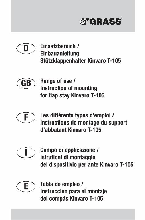
D GB F I E Einsatzbereich / Einbauanleitung Stützklappenhalter Kinvaro T-105 Range of use / Instruction of mounting for flap stay Kinvaro T-105 Les différents types d’emploi / Instructions de montage du support d’abbatant Kinvaro T-105 Campo di applicazione / Istrutioni di montaggio del dispositivio per ante Kinvaro T-105 Tabla de empleo / Instruccion para el montaje del compás Kinvaro T-105
Transcript of Kinvaro T-105 Einbauanleitung 0709 22.07.2009 14:35 Uhr ...
D
GB
F
I
E
Einsatzbereich / EinbauanleitungStützklappenhalter Kinvaro T-105
Range of use / Instruction of mountingfor flap stay Kinvaro T-105
Les différents types d’emploi /Instructions de montage du supportd’abbatant Kinvaro T-105
Campo di applicazione / Istrutioni di montaggiodel dispositivio per ante Kinvaro T-105
Tabla de empleo / Instruccion para el montajedel compás Kinvaro T-105
Kinvaro T-105 Einbauanleitung 0709 22.07.2009 14:35 Uhr Seite 1
2
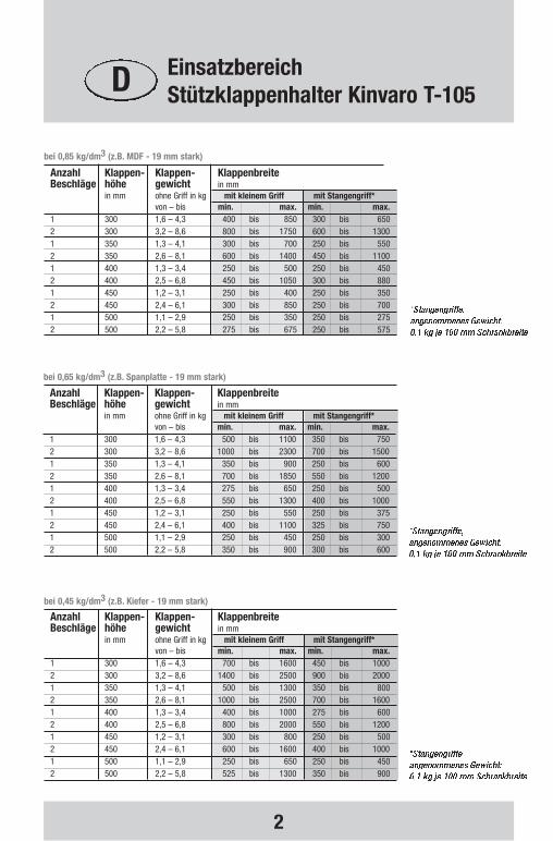
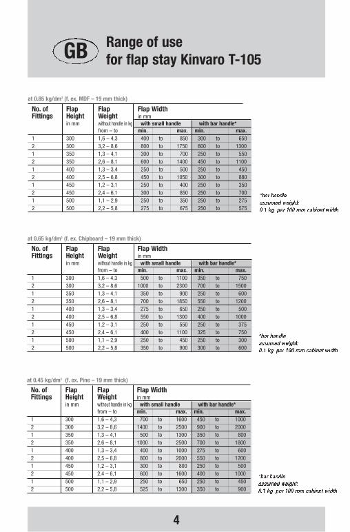
Anzahl Klappen- Klappen- KlappenbreiteBeschläge höhe gewicht in mm
in mm ohne Griff in kg mit kleinem Griff mit Stangengriff*von – bis min. max. min. max.
1 300 1,6 – 4,3 700 bis 1600 450 bis 10002 300 3,2 – 8,6 1400 bis 2500 900 bis 20001 350 1,3 – 4,1 500 bis 1300 350 bis 8002 350 2,6 – 8,1 1000 bis 2500 700 bis 16001 400 1,3 – 3,4 400 bis 1000 275 bis 6002 400 2,5 – 6,8 800 bis 2000 550 bis 12001 450 1,2 – 3,1 300 bis 800 250 bis 5002 450 2,4 – 6,1 600 bis 1600 400 bis 10001 500 1,1 – 2,9 250 bis 650 250 bis 4502 500 2,2 – 5,8 525 bis 1300 350 bis 900
bei 0,45 kg/dm3 (z.B. Kiefer - 19 mm stark)
Anzahl Klappen- Klappen- KlappenbreiteBeschläge höhe gewicht in mm
in mm ohne Griff in kg mit kleinem Griff mit Stangengriff*von – bis min. max. min. max.
1 300 1,6 – 4,3 500 bis 1100 350 bis 7502 300 3,2 – 8,6 1000 bis 2300 700 bis 15001 350 1,3 – 4,1 350 bis 900 250 bis 6002 350 2,6 – 8,1 700 bis 1850 550 bis 12001 400 1,3 – 3,4 275 bis 650 250 bis 5002 400 2,5 – 6,8 550 bis 1300 400 bis 10001 450 1,2 – 3,1 250 bis 550 250 bis 3752 450 2,4 – 6,1 400 bis 1100 325 bis 7501 500 1,1 – 2,9 250 bis 450 250 bis 3002 500 2,2 – 5,8 350 bis 900 300 bis 600
bei 0,65 kg/dm3 (z.B. Spanplatte - 19 mm stark)
Anzahl Klappen- Klappen- KlappenbreiteBeschläge höhe gewicht in mm
in mm ohne Griff in kg mit kleinem Griff mit Stangengriff*von – bis min. max. min. max.
1 300 1,6 – 4,3 400 bis 850 300 bis 6502 300 3,2 – 8,6 800 bis 1750 600 bis 13001 350 1,3 – 4,1 300 bis 700 250 bis 5502 350 2,6 – 8,1 600 bis 1400 450 bis 11001 400 1,3 – 3,4 250 bis 500 250 bis 4502 400 2,5 – 6,8 450 bis 1050 300 bis 8801 450 1,2 – 3,1 250 bis 400 250 bis 3502 450 2,4 – 6,1 300 bis 850 250 bis 7001 500 1,1 – 2,9 250 bis 350 250 bis 2752 500 2,2 – 5,8 275 bis 675 250 bis 575
bei 0,85 kg/dm3 (z.B. MDF - 19 mm stark)
D EinsatzbereichStützklappenhalter Kinvaro T-105
Kinvaro T-105 Einbauanleitung 0709 22.07.2009 14:35 Uhr Seite 2
3
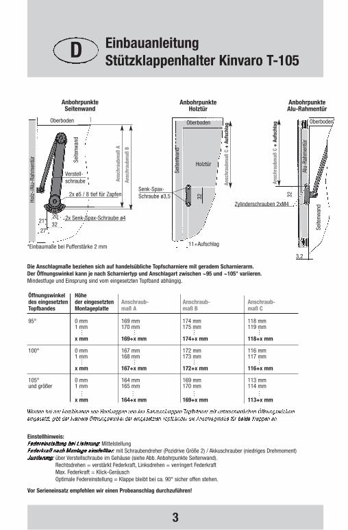
Die Anschlagmaße beziehen sich auf handelsübliche Topfscharniere mit geradem Scharnierarm.Der Öffnungswinkel kann je nach Scharniertyp und Anschlagart zwischen ~95 und ~105° variieren.Mindestfuge und Einsprung sind vom eingesetzten Topfband abhängig.
Vor Serieneinsatz empfehlen wir einen Probeanschlag durchzuführen!
Einstellhinweis:Mittelstellung
mit Schraubendreher (Pozidrive Größe 2) / Akkuschrauber (niedriges Drehmoment)über Verstellschraube im Gehäuse (siehe Abb. Anbohrpunkte Seitenwand).Rechtsdrehen = verstärkt Federkraft, Linksdrehen = verringert FederkraftMax. Federkraft = Klick-Geräusch Optimale Federeinstellung = Klappe bleibt bei ca. 90° sicher offen stehen.
Öffnungswinkel Höhe des eingesetzten der eingesetzten Anschraub- Anschraub- Anschraub-Topfbandes Montageplatte maß A maß B maß C
95° 0 mm 169 mm 174 mm 118 mm 1 mm 170 mm 175 mm 119 mm . . . .. . . .. . . .x mm 169+x mm 174+x mm 118+x mm
100° 0 mm 167 mm 172 mm 116 mm 1 mm 168 mm 173 mm 117 mm . . . .. . . .. . . .x mm 167+x mm 172+x mm 116+x mm
105° 0 mm 164 mm 169 mm 113 mm und größer 1 mm 165 mm 170 mm 114 mm
. . . .. . . .. . . .x mm 164+x mm 169+x mm 113+x mm
*Einbaumaße bei Pufferstärke 2 mm
Anbohrpunkte Seitenwand
Anbohrpunkte Alu-Rahmentür
32
21*32
2x ø5 / 8 tief für Zapfen
20
27*
Senk-Spax-Schraube ø3,5
2x Senk-Spax-Schraube ø4
Oberboden
Seite
nwan
d
Verstell-schraube
Holz
-/Al
u-Ra
hmen
tür
Ansc
hrau
bmaß
A
Ansc
hrau
bmaß
B
Alu-
Rahm
entü
r
32
Oberboden
Zylinderschrauben 2xM4
Seite
nwan
d
Ansc
hrau
bmaß
C +
Auf
schl
ag
11+Aufschlag
Holztür
Oberboden
Seite
nwan
d
Ansc
hrau
bmaß
C +
Auf
schl
ag
Anbohrpunkte Holztür
3,2
D EinbauanleitungStützklappenhalter Kinvaro T-105
Kinvaro T-105 Einbauanleitung 0709 22.07.2009 14:35 Uhr Seite 3
4
No. of Flap Flap Flap WidthFittings Height Weight in mm
in mm without handle in kg with small handle with bar handle*from – to min. max. min. max.
1 300 1,6 – 4,3 700 to 1600 450 to 10002 300 3,2 – 8,6 1400 to 2500 900 to 20001 350 1,3 – 4,1 500 to 1300 350 to 8002 350 2,6 – 8,1 1000 to 2500 700 to 16001 400 1,3 – 3,4 400 to 1000 275 to 6002 400 2,5 – 6,8 800 to 2000 550 to 12001 450 1,2 – 3,1 300 to 800 250 to 5002 450 2,4 – 6,1 600 to 1600 400 to 10001 500 1,1 – 2,9 250 to 650 250 to 4502 500 2,2 – 5,8 525 to 1300 350 to 900
at 0.45 kg/dm3 (f. ex. Pine – 19 mm thick)
No. of Flap Flap Flap WidthFittings Height Weight in mm
in mm without handle in kg with small handle with bar handle*from – to min. max. min. max.
1 300 1,6 – 4,3 500 to 1100 350 to 7502 300 3,2 – 8,6 1000 to 2300 700 to 15001 350 1,3 – 4,1 350 to 900 250 to 6002 350 2,6 – 8,1 700 to 1850 550 to 12001 400 1,3 – 3,4 275 to 650 250 to 5002 400 2,5 – 6,8 550 to 1300 400 to 10001 450 1,2 – 3,1 250 to 550 250 to 3752 450 2,4 – 6,1 400 to 1100 325 to 7501 500 1,1 – 2,9 250 to 450 250 to 3002 500 2,2 – 5,8 350 to 900 300 to 600
at 0.65 kg/dm3 (f. ex. Chipboard – 19 mm thick)
No. of Flap Flap Flap WidthFittings Height Weight in mm
in mm without handle in kg with small handle with bar handle*from – to min. max. min. max.
1 300 1,6 – 4,3 400 to 850 300 to 6502 300 3,2 – 8,6 800 to 1750 600 to 13001 350 1,3 – 4,1 300 to 700 250 to 5502 350 2,6 – 8,1 600 to 1400 450 to 11001 400 1,3 – 3,4 250 to 500 250 to 4502 400 2,5 – 6,8 450 to 1050 300 to 8801 450 1,2 – 3,1 250 to 400 250 to 3502 450 2,4 – 6,1 300 to 850 250 to 7001 500 1,1 – 2,9 250 to 350 250 to 2752 500 2,2 – 5,8 275 to 675 250 to 575
at 0.85 kg/dm3 (f. ex. MDF – 19 mm thick)
GB Range of usefor flap stay Kinvaro T-105
Kinvaro T-105 Einbauanleitung 0709 22.07.2009 14:35 Uhr Seite 4

5
The dimensions are in accordance with standard-trade concealed hinges with straight arm.The opening angle can vary between 95 and 105°, depending upon hinge and degree of opening.Minimum gap depending upon type of concealed hinge used.
Test mounting is recommended before starting series production!
Mounting instructions:mid-position
by use of a screwdriver (Pozidrive Size 2) / powered screwdriver (lowest moment of rotation)by the adjustment screw in the housing of the fitting (see line diagram “Drill Hole Points Side Wall“).Turning to the right = increases the spring tension, turning to the left = decreases spring tension.Maximum spring tension = a clicking sound optimized spring adjustment = the flap remains open securely at approx. 90°.
Opening gap of Height ofconcealed hinges mounting plate Dimension A Dimension B Dimension C
95° 0 mm 169 mm 174 mm 118 mm 1 mm 170 mm 175 mm 119 mm . . . .. . . .. . . .x mm 169+x mm 174+x mm 118+x mm
100° 0 mm 167 mm 172 mm 116 mm 1 mm 168 mm 173 mm 117 mm . . . .. . . .. . . .x mm 167+x mm 172+x mm 116+x mm
105° 0 mm 164 mm 169 mm 113 mm and above 1 mm 165 mm 170 mm 114 mm
. . . .. . . .. . . .x mm 164+x mm 169+x mm 113+x mm
*Installation dimensions at a buffer width of 2 mm
Drill Hole Points Side Wall
32
21*32
2x ø5 / 8 deep for pin
20
27*
countersunkchipboard
screw ø3,5
2x countersunk chipboard screw ø4
top panel
side
wal
l
adjustmentscrew
Woo
den
/ Alu
min
ium
Fra
me
flap
Dim
ensi
on A
Dim
ensi
on B
Alum
iniu
m F
ram
e fla
p
32
top panel
countersunk screw 2xM4
side
wal
l
Dim
ensi
on C
+ o
verla
y “t
op“
11+overlay
Wooden flap
top panel
side
wal
l
Dim
ensi
on C
+ o
verla
y “t
op“
Drill Hole PointsWooden Door
Drill Hole Points Aluminium Frame Door
3,2
GB Instruction of mountingfor flap stay Kinvaro T-105
Kinvaro T-105 Einbauanleitung 0709 22.07.2009 14:35 Uhr Seite 5
6
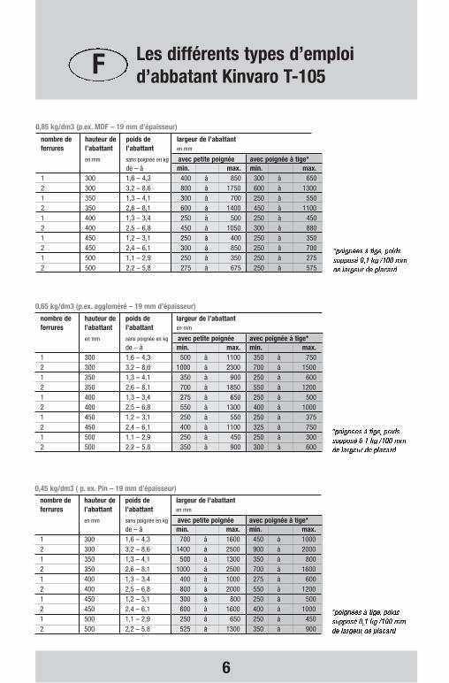
nombre de hauteur de poids de largeur de l’abattantferrures l’abattant l’abattant en mm
en mm sans poignée en kg avec petite poignée avec poignée à tige*de – à min. max. min. max.
1 300 1,6 – 4,3 700 à 1600 450 à 10002 300 3,2 – 8,6 1400 à 2500 900 à 20001 350 1,3 – 4,1 500 à 1300 350 à 8002 350 2,6 – 8,1 1000 à 2500 700 à 16001 400 1,3 – 3,4 400 à 1000 275 à 6002 400 2,5 – 6,8 800 à 2000 550 à 12001 450 1,2 – 3,1 300 à 800 250 à 5002 450 2,4 – 6,1 600 à 1600 400 à 10001 500 1,1 – 2,9 250 à 650 250 à 4502 500 2,2 – 5,8 525 à 1300 350 à 900
0,45 kg/dm3 ( p. ex. Pin – 19 mm d’épaisseur)
nombre de hauteur de poids de largeur de l’abattantferrures l’abattant l’abattant en mm
en mm sans poignée en kg avec petite poignée avec poignée à tige*de – à min. max. min. max.
1 300 1,6 – 4,3 500 à 1100 350 à 7502 300 3,2 – 8,6 1000 à 2300 700 à 15001 350 1,3 – 4,1 350 à 900 250 à 6002 350 2,6 – 8,1 700 à 1850 550 à 12001 400 1,3 – 3,4 275 à 650 250 à 5002 400 2,5 – 6,8 550 à 1300 400 à 10001 450 1,2 – 3,1 250 à 550 250 à 3752 450 2,4 – 6,1 400 à 1100 325 à 7501 500 1,1 – 2,9 250 à 450 250 à 3002 500 2,2 – 5,8 350 à 900 300 à 600
0,65 kg/dm3 (p.ex. aggloméré – 19 mm d’épaisseur)
nombre de hauteur de poids de largeur de l’abattantferrures l’abattant l’abattant en mm
en mm sans poignée en kg avec petite poignée avec poignée à tige*de – à min. max. min. max.
1 300 1,6 – 4,3 400 à 850 300 à 6502 300 3,2 – 8,6 800 à 1750 600 à 13001 350 1,3 – 4,1 300 à 700 250 à 5502 350 2,6 – 8,1 600 à 1400 450 à 11001 400 1,3 – 3,4 250 à 500 250 à 4502 400 2,5 – 6,8 450 à 1050 300 à 8801 450 1,2 – 3,1 250 à 400 250 à 3502 450 2,4 – 6,1 300 à 850 250 à 7001 500 1,1 – 2,9 250 à 350 250 à 2752 500 2,2 – 5,8 275 à 675 250 à 575
0,85 kg/dm3 (p.ex. MDF – 19 mm d’épaisseur)
F Les différents types d’emploid’abbatant Kinvaro T-105
Kinvaro T-105 Einbauanleitung 0709 22.07.2009 14:35 Uhr Seite 6
7
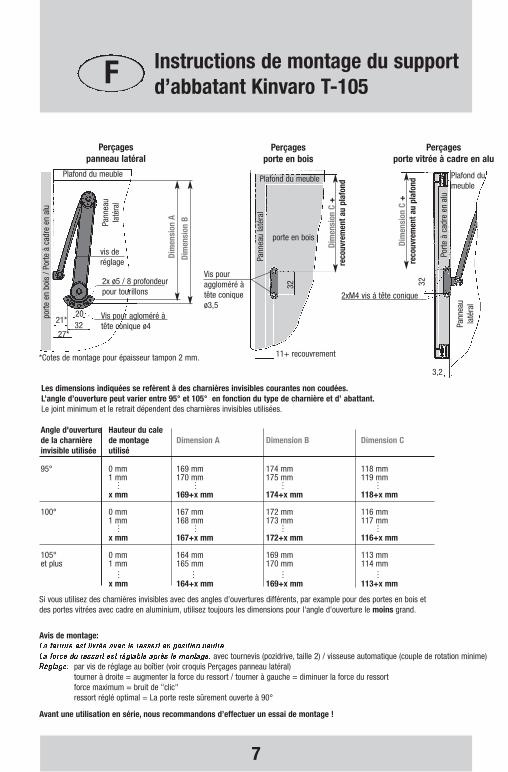
Les dimensions indiquées se refèrent à des charnières invisibles courantes non coudées.L’angle d’ouverture peut varier entre 95° et 105° en fonction du type de charnière et d’ abattant.Le joint minimum et le retrait dépendent des charnières invisibles utilisées.
Avant une utilisation en série, nous recommandons d’effectuer un essai de montage !
Avis de montage:
avec tournevis (pozidrive, taille 2) / visseuse automatique (couple de rotation minime)par vis de réglage au boîtier (voir croquis Perçages panneau latéral)tourner à droite = augmenter la force du ressort / tourner à gauche = diminuer la force du ressortforce maximum = bruit de "clic"ressort réglé optimal = La porte reste sûrement ouverte à 90°
Angle d'ouverture Hauteur du cale de la charnière de montage Dimension A Dimension B Dimension Cinvisible utilisée utilisé
95° 0 mm 169 mm 174 mm 118 mm 1 mm 170 mm 175 mm 119 mm . . . .. . . .. . . .x mm 169+x mm 174+x mm 118+x mm
100° 0 mm 167 mm 172 mm 116 mm 1 mm 168 mm 173 mm 117 mm . . . .. . . .. . . .x mm 167+x mm 172+x mm 116+x mm
105° 0 mm 164 mm 169 mm 113 mm et plus 1 mm 165 mm 170 mm 114 mm
. . . .. . . .. . . .x mm 164+x mm 169+x mm 113+x mm
Si vous utilisez des charnières invisibles avec des angles d'ouvertures différents, par example pour des portes en bois etdes portes vitrées avec cadre en aluminium, utilisez toujours les dimensions pour l'angle d'ouverture le moins grand.
*Cotes de montage pour épaisseur tampon 2 mm.
Perçages panneau latéral
Perçages porte vitrée à cadre en alu
32
21*32
2x ø5 / 8 profondeurpour tourillons
20
27*
Vis pouraggloméré à tête conique ø3,5
Vis pour agloméré àtête conique ø4
Plafond du meuble
Pann
eau
laté
ral
vis deréglage
porte
en
bois
/ Po
rte à
cad
re e
n al
u
Dim
ensi
on A
Dim
ensi
on B
Porte
à c
adre
en
alu
32
Plafond dumeuble
2xM4 vis á tête conique
Pann
eau
laté
ral
Dim
ensi
on C
+
reco
uvre
men
t au
plaf
ond
11+ recouvrement
porte en bois
Plafond du meuble
Pann
eau
laté
ral
Dim
ensi
on C
+
reco
uvre
men
t au
plaf
ond
Perçages porte en bois
3,2
F Instructions de montage du supportd’abbatant Kinvaro T-105
Kinvaro T-105 Einbauanleitung 0709 22.07.2009 14:35 Uhr Seite 7

8
Nr. Altezza Peso ante Larghezza antedispositivi ante senza maniglia in mm
in mm in kg con piccola maniglia con maniglia a tubo*min. – max. min. max. min. max.
1 300 1,6 – 4,3 700 fino al 1600 450 fino al 10002 300 3,2 – 8,6 1400 fino al 2500 900 fino al 20001 350 1,3 – 4,1 500 fino al 1300 350 fino al 8002 350 2,6 – 8,1 1000 fino al 2500 700 fino al 16001 400 1,3 – 3,4 400 fino al 1000 275 fino al 6002 400 2,5 – 6,8 800 fino al 2000 550 fino al 12001 450 1,2 – 3,1 300 fino al 800 250 fino al 5002 450 2,4 – 6,1 600 fino al 1600 400 fino al 10001 500 1,1 – 2,9 250 fino al 650 250 fino al 4502 500 2,2 – 5,8 525 fino al 1300 350 fino al 900
da 0,45 kg/dm3 (p.e.. pino - spessore 19 mm )
Nr. Altezza Peso ante Larghezza antedispositivi ante senza maniglia in mm
in mm in kg con piccola maniglia con maniglia a tubo*min. – max. min. max. min. max.
1 300 1,6 – 4,3 500 fino al 1100 350 fino al 7502 300 3,2 – 8,6 1000 fino al 2300 700 fino al 15001 350 1,3 – 4,1 350 fino al 900 250 fino al 6002 350 2,6 – 8,1 700 fino al 1850 550 fino al 12001 400 1,3 – 3,4 275 fino al 650 250 fino al 5002 400 2,5 – 6,8 550 fino al 1300 400 fino al 10001 450 1,2 – 3,1 250 fino al 550 250 fino al 3752 450 2,4 – 6,1 400 fino al 1100 325 fino al 7501 500 1,1 – 2,9 250 fino al 450 250 fino al 3002 500 2,2 – 5,8 350 fino al 900 300 fino al 600
da 0,65 kg/dm3 (p.e. legno truciolato - spessore 19 mm )
Nr. Altezza Peso ante Larghezza antedispositivi ante senza maniglia in mm
in mm in kg con piccola maniglia con maniglia a tubo*min. – max. min. max. min. max.
1 300 1,6 – 4,3 400 fino al 850 300 fino al 6502 300 3,2 – 8,6 800 fino al 1750 600 fino al 13001 350 1,3 – 4,1 300 fino al 700 250 fino al 5502 350 2,6 – 8,1 600 fino al 1400 450 fino al 11001 400 1,3 – 3,4 250 fino al 500 250 fino al 4502 400 2,5 – 6,8 450 fino al 1050 300 fino al 8801 450 1,2 – 3,1 250 fino al 400 250 fino al 3502 450 2,4 – 6,1 300 fino al 850 250 fino al 7001 500 1,1 – 2,9 250 fino al 350 250 fino al 2752 500 2,2 – 5,8 275 fino al 675 250 fino al 575
da 0,85 kg/dm3 (p.e. MDF - spessore 19 mm )
I Campo di applicazione del dispositivio per ante Kinvaro T-105
Kinvaro T-105 Einbauanleitung 0709 22.07.2009 14:35 Uhr Seite 8
9
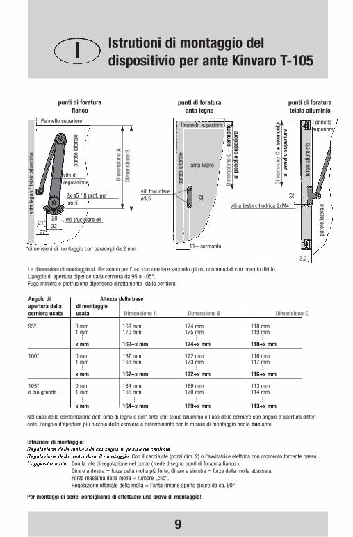
Le dimensioni di montaggio si riferiscono per l’uso con cerniere secondo gli usi commerciali con braccio diritto.L’angolo di apertura dipende dalla cerniera da 95 a 105°.Fuga minima e protrusione dipendono direttamente dalla cerniera.
Per montaggi di serie consigliamo di effettuare una prova di montaggio!
Istruzioni di montaggio:
Con il cacciavite (pozzi dim. 2) o l’avvitatrice elettrica con momento torcente basso.Con la vite di regolazione nel corpo ( vede disegno punti di foratura fianco ).Girare a destra = forza della molla più forte, Girare a sinistra = forza della molla abassata.Forza massima della molla = rumore „clic“.Regolazione ottimale della molla = l’anta rimane aperto sicuro da ca. 90°.
Angolo di Altezza della base apertura della di montaggio cerniera usata usata Dimensione A Dimensione B Dimensione C
95° 0 mm 169 mm 174 mm 118 mm 1 mm 170 mm 175 mm 119 mm . . . .. . . .. . . .x mm 169+x mm 174+x mm 118+x mm
100° 0 mm 167 mm 172 mm 116 mm 1 mm 168 mm 173 mm 117 mm . . . .. . . .. . . .x mm 167+x mm 172+x mm 116+x mm
105° 0 mm 164 mm 169 mm 113 mm e più grande 1 mm 165 mm 170 mm 114 mm
. . . .. . . .. . . .x mm 164+x mm 169+x mm 113+x mm
Nel caso della combinazione dell‘ ante di legno e dell‘ ante con telaio alluminio e l’uso delle cerniere con angolo d’apertura differ-ente, l’angolo d’apertura più piccolo delle cerniere è determinante per le misure di montaggio per le due ante.
*dimensioni di montaggio con paracolpi da 2 mm
punti di foratura fianco
punti di foratura telaio alluminio
32
21*32
2x ø5 / 8 prof. perperni
20
27*
viti truciolare ø3,5
viti truciolare ø4
Pannello superiore
pare
te la
tera
le
vite di regolazione
anta
legn
o / t
elai
o al
lum
inio
Dim
ensi
one
A
Dim
ensi
one
B
tela
io a
llum
inio
32
Pannellosuperiore
viti a testa cilindrica 2xM4
pare
te la
tera
le
Dim
ensi
one
C+
sor
mon
toal
pen
ello
sup
erio
re
11+ sormonto
anta legno
Pannello superiore
pare
te la
tera
le
Dim
ensi
one
C+
sor
mon
toal
pen
ello
sup
erio
re
punti di foraturaanta legno
3,2
I Istrutioni di montaggio del dispositivio per ante Kinvaro T-105
Kinvaro T-105 Einbauanleitung 0709 22.07.2009 14:35 Uhr Seite 9
10
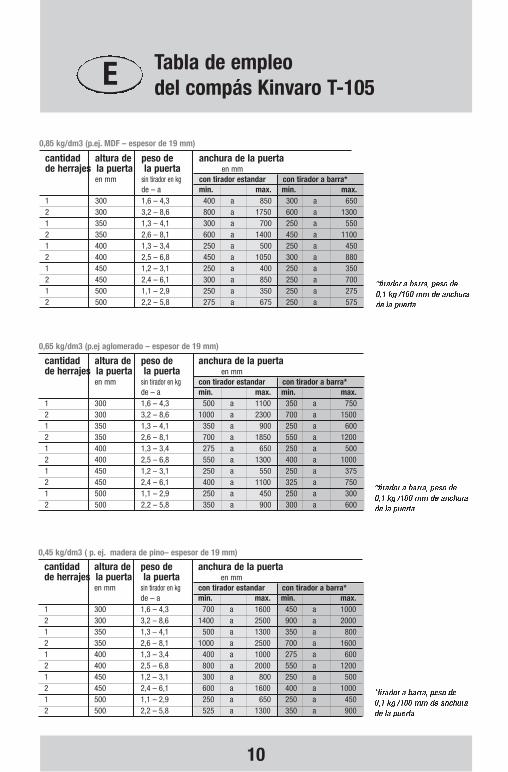
cantidad altura de peso de anchura de la puertade herrajes la puerta la puerta en mm
en mm sin tirador en kg con tirador estandar con tirador a barra*de – a min. max. min. max.
1 300 1,6 – 4,3 700 a 1600 450 a 10002 300 3,2 – 8,6 1400 a 2500 900 a 20001 350 1,3 – 4,1 500 a 1300 350 a 8002 350 2,6 – 8,1 1000 a 2500 700 a 16001 400 1,3 – 3,4 400 a 1000 275 a 6002 400 2,5 – 6,8 800 a 2000 550 a 12001 450 1,2 – 3,1 300 a 800 250 a 5002 450 2,4 – 6,1 600 a 1600 400 a 10001 500 1,1 – 2,9 250 a 650 250 a 4502 500 2,2 – 5,8 525 a 1300 350 a 900
0,45 kg/dm3 ( p. ej. madera de pino– espesor de 19 mm)
cantidad altura de peso de anchura de la puertade herrajes la puerta la puerta en mm
en mm sin tirador en kg con tirador estandar con tirador a barra*de – a min. max. min. max.
1 300 1,6 – 4,3 500 a 1100 350 a 7502 300 3,2 – 8,6 1000 a 2300 700 a 15001 350 1,3 – 4,1 350 a 900 250 a 6002 350 2,6 – 8,1 700 a 1850 550 a 12001 400 1,3 – 3,4 275 a 650 250 a 5002 400 2,5 – 6,8 550 a 1300 400 a 10001 450 1,2 – 3,1 250 a 550 250 a 3752 450 2,4 – 6,1 400 a 1100 325 a 7501 500 1,1 – 2,9 250 a 450 250 a 3002 500 2,2 – 5,8 350 a 900 300 a 600
0,65 kg/dm3 (p.ej aglomerado – espesor de 19 mm)
cantidad altura de peso de anchura de la puertade herrajes la puerta la puerta en mm
en mm sin tirador en kg con tirador estandar con tirador a barra*de – a min. max. min. max.
1 300 1,6 – 4,3 400 a 850 300 a 6502 300 3,2 – 8,6 800 a 1750 600 a 13001 350 1,3 – 4,1 300 a 700 250 a 5502 350 2,6 – 8,1 600 a 1400 450 a 11001 400 1,3 – 3,4 250 a 500 250 a 4502 400 2,5 – 6,8 450 a 1050 300 a 8801 450 1,2 – 3,1 250 a 400 250 a 3502 450 2,4 – 6,1 300 a 850 250 a 7001 500 1,1 – 2,9 250 a 350 250 a 2752 500 2,2 – 5,8 275 a 675 250 a 575
0,85 kg/dm3 (p.ej. MDF – espesor de 19 mm)
E Tabla de empleodel compás Kinvaro T-105
Kinvaro T-105 Einbauanleitung 0709 22.07.2009 14:35 Uhr Seite 10
11
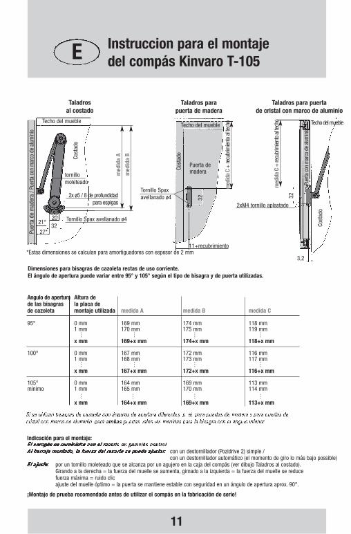
Dimensiones para bisagras de cazoleta rectas de uso corriente.El ángulo de apertura puede variar entre 95° y 105° según el tipo de bisagra y de puerta utilizadas.
¡Montaje de prueba recomendado antes de utilizar el compás en la fabricación de serie!
Indicación para el montaje:
con un destornillador (Pozidrive 2) simple / con un destornillador automático (el momento de giro lo más bajo possible)
por un tornillo moleteado que se alcanza por un agujero en la caja del compás (ver dibujo Taladros al costado).Girando a la derecha = la fuerza del muelle se aumenta, girnado a la izquierda = la fuerza del muelle se reducefuerza máxima = ruido clic ajuste del muelle óptimo = la puerta se mantiene estable con seguridad en un ángulo de apertura aprox. 90°.
Angulo de apertura Altura de de las bisagras la placa de de cazoleta montaje utilizada medida A medida B medida C
95° 0 mm 169 mm 174 mm 118 mm 1 mm 170 mm 175 mm 119 mm . . . .. . . .. . . .x mm 169+x mm 174+x mm 118+x mm
100° 0 mm 167 mm 172 mm 116 mm 1 mm 168 mm 173 mm 117 mm . . . .. . . .. . . .x mm 167+x mm 172+x mm 116+x mm
105° 0 mm 164 mm 169 mm 113 mm mínimo 1 mm 165 mm 170 mm 114 mm
. . . .. . . .. . . .x mm 164+x mm 169+x mm 113+x mm
*Estas dimensiones se calculan para amortiguadores con espesor de 2 mm
Taladros al costado
Taladros para puertade cristal con marco de aluminio
32
21*32
2x ø5 / 8 de profundidad para espigas
20
27*
Tornillo Spaxavellanado ø4
Tornillo Spax avellanado ø4
Techo del mueble
Cost
ado
tornillomoleteado
Puer
ta d
e m
ader
a / P
uerta
con
mar
co d
e al
umin
io
med
ida
A
med
ida
B
Puer
ta c
on m
arco
de
alum
inio
32
Techo del mueble
2xM4 tornillo aplastado
3,2
Cost
ado
med
ida
C+
recu
brim
iento
al te
cho
11+recubrimiento
Puerta demadera
Techo del mueble
Cost
ado
med
ida
C+
recu
brim
iento
al te
cho
Taladros parapuerta de madera
E Instruccion para el montajedel compás Kinvaro T-105
Kinvaro T-105 Einbauanleitung 0709 22.07.2009 14:35 Uhr Seite 11

12
HETAL-Werke Franz Hettich GmbH & Co. KB
P.O.Box 12 40 D-72272 AlpirsbachGermany
Phone +49 / 74 44 / 68-0Fax +49 / 74 44 / 68-110e-mail: [email protected] http://www.grass.at
F151
1451
5089
8/HE
/070
9
Kinvaro T-105 Einbauanleitung 0709 22.07.2009 14:35 Uhr Seite 12
F151
1451
5089
8/H
E/05
15
T-105