Linear Elastic FE-Analysis of Porous, Laser Welded, Heat ...
14
materials Article Linear Elastic FE-Analysis of Porous, Laser Welded, Heat Treatable, Aluminium High Pressure Die Castings based on X-Ray Computed Tomography Data Fabian Teichmann 1, * , Arne Ziemer 1 , Martin Leitner 2 , Jonas Hensel 1 and Klaus Dilger 1 1 Technische Universität Braunschweig, Institute of Joining and Welding, Langer Kamp 8, D-38106 Braunschweig, Germany; [email protected] (A.Z.); [email protected] (J.H.); [email protected] (K.D.) 2 Montanuniversität Loeben, Department Product Engineering, Chair of Mechanical Engineering, Franz-Josef-Strasse 18, 8700 Leoben, Austria; [email protected] * Correspondence: [email protected]; Tel.: +49-531-391-95573 Received: 18 February 2020; Accepted: 16 March 2020; Published: 20 March 2020 Abstract: The welding of aluminium high pressure die castings is a well known and broadly investigated challenge in various fields of industry and research. Prior research in this specific field mainly focused on the optimisation of the welding and the casting process and on the cause of the frequently occurring porosity and incomplete fusion phenomena, whereas the impacts of these defects have hardly been addressed. Therefore, the underlying study presents the investigation of weldments in EN AC-AlSi10MnMg high pressure aluminium die castings by linear elastic finite element analysis based on X-ray computed tomography as a novel approach. Hereby, four laser weldments with differing surfaces and pore contents were investigated by X-ray computed tomography and tensile testing. Based on the voxel datasets of the porous weldments, triangular finite element meshes were generated and a numerical finite element analysis was conducted. Good agreement of the stress–strain curves between the simulations and the experiments was achieved. Keywords: laser welding; high pressure aluminium die casting; aluminium; AC-AlSi10MnMg; X-ray computed tomography; finite elements; mesh; structural simulation 1. Introduction 1.1. Defects in Laser Welded Aluminium High Pressure Die Castings The occurrence of weld bead porosity and incomplete fusion are well known issues when welding aluminium, high pressure die casting (HPDC) alloys [1,2]. According to the German Welding Society [3], the cause of the porosity can be distinguished in metallurgical and mechanical pore formation. In the case of metallurgically formed pores, hydrogen is released into the melt, e.g., by the dissociation of aluminium hydrides, agglomerates within the melt pool and is trapped in the weld metal during the solidification of the melt. In the case of mechanical pore formation, inclusions or pores present within the die casting part are heated rapidly by the laser beam during the welding process. The heat input causes a rapid expansion of the pores, which leads to pore formation in the weld metal, an ejection of the molten metal and/or incomplete fusion. Thus, the weldability of high pressure aluminium die castings depends, amongst other factors, on the presence of inclusions and the hydrogen content [4]. Materials 2020, 13, 1420; doi:10.3390/ma13061420 www.mdpi.com/journal/materials
Transcript of Linear Elastic FE-Analysis of Porous, Laser Welded, Heat ...

materials
Article
Linear Elastic FE-Analysis of Porous, Laser Welded,Heat Treatable, Aluminium High Pressure DieCastings based on X-Ray Computed TomographyData
Fabian Teichmann 1,* , Arne Ziemer 1, Martin Leitner 2 , Jonas Hensel 1 and Klaus Dilger 1
1 Technische Universität Braunschweig, Institute of Joining and Welding, Langer Kamp 8,D-38106 Braunschweig, Germany; [email protected] (A.Z.); [email protected] (J.H.);[email protected] (K.D.)
2 Montanuniversität Loeben, Department Product Engineering, Chair of Mechanical Engineering,Franz-Josef-Strasse 18, 8700 Leoben, Austria; [email protected]
* Correspondence: [email protected]; Tel.: +49-531-391-95573
Received: 18 February 2020; Accepted: 16 March 2020; Published: 20 March 2020�����������������
Abstract: The welding of aluminium high pressure die castings is a well known and broadlyinvestigated challenge in various fields of industry and research. Prior research in this specific fieldmainly focused on the optimisation of the welding and the casting process and on the cause of thefrequently occurring porosity and incomplete fusion phenomena, whereas the impacts of these defectshave hardly been addressed. Therefore, the underlying study presents the investigation of weldmentsin EN AC-AlSi10MnMg high pressure aluminium die castings by linear elastic finite element analysisbased on X-ray computed tomography as a novel approach. Hereby, four laser weldments withdiffering surfaces and pore contents were investigated by X-ray computed tomography and tensiletesting. Based on the voxel datasets of the porous weldments, triangular finite element mesheswere generated and a numerical finite element analysis was conducted. Good agreement of thestress–strain curves between the simulations and the experiments was achieved.
Keywords: laser welding; high pressure aluminium die casting; aluminium; AC-AlSi10MnMg; X-raycomputed tomography; finite elements; mesh; structural simulation
1. Introduction
1.1. Defects in Laser Welded Aluminium High Pressure Die Castings
The occurrence of weld bead porosity and incomplete fusion are well known issues whenwelding aluminium, high pressure die casting (HPDC) alloys [1,2]. According to the German WeldingSociety [3], the cause of the porosity can be distinguished in metallurgical and mechanical poreformation. In the case of metallurgically formed pores, hydrogen is released into the melt, e.g., by thedissociation of aluminium hydrides, agglomerates within the melt pool and is trapped in the weldmetal during the solidification of the melt. In the case of mechanical pore formation, inclusions orpores present within the die casting part are heated rapidly by the laser beam during the weldingprocess. The heat input causes a rapid expansion of the pores, which leads to pore formation in theweld metal, an ejection of the molten metal and/or incomplete fusion. Thus, the weldability of highpressure aluminium die castings depends, amongst other factors, on the presence of inclusions and thehydrogen content [4].
Materials 2020, 13, 1420; doi:10.3390/ma13061420 www.mdpi.com/journal/materials

Materials 2020, 13, 1420 2 of 14
Many studies have aimed to reduce the weld bead porosity and incomplete fusion. Thereby,measures considering the welding process were taken, as were those focused on the casting process.In terms of an optimisation of the casting process, Wiesner [4] stated that a sparse use of wax free, lowconcentrated lubricants and release agents has a favourable effect on the welding outcome. Moreoverthe application of vacuum high pressure die casting is a state of the art measure to positively influencethe number of inclusions and the hydrogen content in a die casting part [2]. This, subsequently,enhances the weldability as well. Considering beam welding processes, many approaches were takento optimise the welding outcome. Winkler [5] established the application of dual beam laser weldingas an advantageous method to reduce porosity and to enhance the mechanical properties of the weldedprobes. Dittrich et al. [6] introduced laser welding with high frequency beam deflection as a methodwith which to feasibly achieve dissimilar welds of aluminium cast and aluminium wrought alloys.Fritzsche et al. [7] investigated the electromagnetic degassing of aluminium die castings during laserbeam welding and found a positive influence of the electromagnetic forces on the welding outcome.In addition, the authors of the current study confirmed in prior research that dual beam laser weldinghas a positive impact on the weld bead quality [8,9]. In the same research it was found that the ambientpressure during laser welding had a strong influence on the amount, size and shape of the occurringweld metal porosity. Krahn et al. [10] reported a generally positive influence of multi spot electronbeam welding on the occurrence of welding defects. These findings were further investigated andconfirmed [11]. Despite the large variety of research carried out on the welding of aluminium highpressure die castings, the influence of the typically occurring welding defects on tensile strength andfatigue has not been investigated in detail.
Aside from aluminium HPDC alloys different research on laser vacuum welding of a broadvariety of materials have been carried out in the past [12]. Experimental research has shown that thevacuum has several influences on the welding process and its outcome: For example, the increaseof penetration depth, the degeneration of the vapour plume and the decrease of weld spatter wereshown by diffrent authors [13–16]. In addition, Luo et al. [17] achieved the effects mentioned by theapplication of a local vacuum chamber during laser welding. Moreover, these observations wereproven by numerical simulations of the welding process of Pang et al. [18]. Detailed investigations onthe formation of porosity during laser vacuum welding of steel and aluminium have been carried outby Jiang et al. [19]. Jiang identified that the liquid metal flow around the keyhole changes its directionto an upward flow behind the keyhole. This upward flow accelerates gas bubbles in the melt andhence improves degassing.
1.2. Voxel-Based Numerical Simulation
Voxel-based numerical simulations have been carried out in different studies for variouspurposes [20–30]. Therein, different approaches were taken, such as the generation of tetrahedralmeshes from the voxel data, the calculation on the voxel grids using the boundary element methodand the boolean subtraction of extracted defects from virtual test specimens.
The basic idea, to utilise voxel data generated by X-ray computed tomography for numericalsimulations, was already investigated in the health sciences during the 90s; for example, in [20].Bossart et al. [20] demonstrated the tetrahedral volumetric mesh generation of a metacarpal bone. Thisapproach was continued by others, such as Fang et al. [21], who investigated the tetrahedral meshgeneration from volumetric images. The same approach was applied by Walle et al. [23]. In this study,the authors created tetrahedral meshes from XCT voxel data to predict the conductivity of poroussintered glass fibre material.
Nicoletto et al. [24] discussed the influence of casting pores on the fatigue behaviour of Al-Sialloys. The authors extracted a single pore from an X-ray computed tomography scan, embedded thispore as a void in various directions in a virtual tensile test specimen and investigated the impact of thepore on the fatigue behaviour. It was shown that the method is feasible for investigating the influence
Materials 2020, 13, 1420 3 of 14
of complex 3D pore morphology on the fatigue behaviour. Wicke et al. [25] used the same approachand claimed the approach to be feasible for identifying stress concentrations.
Fieres et al. applied the voxel-based boundary element simulation method in [31] to predict stressaccumulations in porous 3D printed parts and tensile test specimens made from aluminium. Based onthe simulations, the authors were able to predict the stress distribution in the parts and test specimens,and the location of crack initiation and force necessary for the crack initiation. The presented approachis limited to elastic material behaviour and static loading. Despite these limitations, the results wereaccurate. Furthermore, Du Plessis et al. applied the same approach in [26] to investigate the impactof porosity in cast titanium Ti6Al4V on the tensile strength. The investigation of numerous testspecimens using X-ray micro-computed tomography, tensile testing and numerical simulations, leadto the conclusion that the pores had an influence on the ductility and the location of failure. Moreoverthe authors were able to show that the simulation method is feasible for predicting both effects.
The influence of porosity on the fatigue behaviour of additively manufactured Ti6Al4V wasinvestigated by Tammas-Williams et al. [27] under the use of voxel-based finite element simulation.The authors produced tensile test specimens by the use of electron beam melting, conducted an X-raycomputed tomography analysis and performed interrupted fatigue tests. From the XCT voxel datathey derived FE-meshes and simulated the fatigue loading. Using this method, the authors wereable to visualise the stress distribution in the region of defects and to draw conclusions about themanufacturing process.
Serrano-Munoz et al. [28] performed a similar test series on the influence of casting defects onthe fatigue life of A357-T6 cast aluminium alloy. Their investigations used synchrotron in situ fatiguetesting and image-based finite element simulation to assess the effects of the shapes and sizes of castingdefects on the fatigue life. Using this method, the authors proved that both affect the fatigue life.
Together, these studies indicate that the effects of defects in aluminium HPDC parts and additivelymanufactured parts from aluminium on fatigue and strength have been investigated by differentauthors. Moreover, these studies have shown X-ray computed tomography is a feasible methodwith which to obtain realistic data of a test specimen containing inner and outer defects. Based onthis data, realistic finite element meshes can be obtained or factors for the fatigue assessment can bederived. Since this method has not been investigated for welded joints from aluminium HPDC alloy,the current research aims to apply X-ray computed tomography based finite element simulation toporous, laser welded, aluminium high pressure die castings. In the scope of the underlying study is thegeneration of triangular finite element meshes containing a large number of pores and outer defects,such as undercuts or incomplete fusion. As a long-term goal, the results of the current investigationare planned to be used as a basis for the assessment of the impacts of different defects on the fatiguebehaviour.
2. Materials and Experimental Method
The current study aims to investigate welded aluminium high pressure die castings containingtypical defects related to welding by the use of voxel-based finite element simulations. Therefore,four test welds were created by laser vacuum welding. Tensile test specimens were taken from thewelds and an X-ray computed tomography (XCT) analysis was performed. Subsequently, the testspecimens underwent a tensile test. Based on the voxel data of the XCT-analysis, numerical finiteelement simulations were carried out and compared to the experimental results of the tensile tests.
2.1. Materials
For the underlying investigation, aluminium high pressure die casting test plates of dimensions260 × 150 × 4 mm3 were casted on a BÜHLER EVOLUTION B 53D HPDC machine. The castingswere produced by vacuum high pressure die casting with the use of rotor degassing to reduce thedensity index, and subsequently, the hydrogen content. The density index is a quality measure for gasremaining entrapped within the casted aluminium part and correlates strongly to the hydrogen content,

Materials 2020, 13, 1420 4 of 14
as shown in [32]. During the casting process, the wax-free release agent SL 1697 S, manufactured byCHEMTREND, was applied. The resulting test plates were casted from the alloy EN AC-AlSi10MnMgwith a density index of 0.8% .
2.2. Laser Vacuum Welding
As described above, the reduction of the ambient pressure during laser beam welding has asignificant influence on the welding outcome. When welding high pressure aluminium die castings,the ambient pressure present during welding has a strong impact on the amount, size and shape of theoccurring porosity. Thus, numerous laser welding trials were performed at different ambient pressurelevels of 100 hPa and 0.1 hPa to create a wide variety of welding outcomes. The laser source appliedwas a Yb:YAG disk laser emitting continuous light of 1030 nm with a beam parameter product of8 mm×mrad. The processing optics applied had a collimation of 200 mm and a focal length of 280 mm,resulting in a focal spot 280 µm in diameter. The focal position during welding was set to −2 mm forall the welds performed, and the welding velocity was fixed at 2 m/min. Since welding under subatmospheric conditions increases the penetration depth, the laser power was reduced according toTable 1 to achieve a fully penetrating weld in 4 mm thick aluminium. All welding trials were repeatedthree times, and seven test specimens were taken from each weld bead. From the specimens created inthe described manner, four representative test specimens containing typical defects were selected andanalysed as described below.
Table 1. Welding parameters of the selected test specimens.
Specimen Laser power Ambient pressure– W hPa
A 2960 100B 2960 100C 2800 0.1D 2800 0.1
2.3. X-Ray Computed Tomography
The X-ray computed tomography analysis was performed with a common commercially availablescanner. For each scan, four tensile test specimens were mounted in a 3D printed polylactic jig.The XCT-scans were conducted under constant rotation of the specimens with 1442 images per scan.The exposure time was set to 100 ms, the tube voltage to 200 kV and the beam current to 180 µA. Thissetup resulted in a voxel size of 45.39 µm. The specimens selected for the current study were takenfrom a larger majority of samples, created for a previous study described in [33,34]. It has to be notedthat the scanning parameters were predominantly optimised for time. The tensile testing specimenswere XCT tested in the welded region only, as illustrated in Figure 1. The XCT-scans were reconstructedusing the commercially available software phoenix datos|X. The porosity analysis was performed usingthe software VGStudioMax 3.2. From the porosity analysis, the number of pores for each weld beadand the sizes of the smallest and largest pores were extracted. Moreover, the mean sphericity of thepores detected within one weldment was calculated. Hereby, the sphericity is defined as the ratio ofthe surface of a perfect sphere with the same volume as the particle in consideration and the surface ofthe particle in question [35,36].
y
x
z
Figure 1. Welded tensile test specimen, area of XCT testing highlighted in red.

Materials 2020, 13, 1420 5 of 14
Within the XCT-scans, the coordinates are defined as follows: the x-axis points in the weldingdirection, the y-axis orthogonal to the welding direction and the z-axis in the direction of the penetrationdepth of the welding, as shown in Figure 5a. After the XCT-testing, the specimens underwent atensile test.
2.4. Tensile Testing
The weld beads were created in the middle of the die casting plates, as Figures 1 and 2 indicate.From each weld, seven test specimens were taken by the use of waterjet cutting; see Figure 2. All testsamples underwent a tensile test based on the DIN EN ISO 6892-1 [37] standard, using an INSTRON
5567 universal testing machine, consisting of a maximum test load of 30 kN. The tensile tests werecarried out at a testing velocity of 1 mm/min; the strain was measured using an INSTON AVE 2663-821Videoextensometer.
150
260,0026,00
141,0
0
25,74
115,26
65,00
R15,52
x
y
Figure 2. Geometry and location of extraction of the test specimens from the 4 mm thick high pressuredie casting (HPDC) plate.
3. Numerical Method
The current study aims to investigate the feasibility of voxel-based structural finite elementsimulations of complex welded joints in high pressure aluminium die castings containing innerand outer defects related to welding. For this purpose, four datasets of XCT-data were chosen andsubmitted to the meshing algorithm described below. Afterwards, the meshes were used to conduct anelastic FE-Simulation of uniaxial loading. The results of the simulation were compared to the results ofthe experiments. In the current investigation, triangular meshes from differing sets of voxel data werecreated by the application of a custom-made algorithm using MATLAB.
3.1. Mesh Generation
Figure 3 depicts a flowchart of the proposed algorithm for the finite element mesh generation:Firstly, the XCT-scan is reconstructed, registered and analysed for pores using VGStudioMax. Secondly,the resulting volume is binarised using a global threshold approach. Afterwards, surfaces within thevolume data are calculated and repaired in a further step. Based on the resulting surfaces, the spacebetween the surfaces of the body and the pores is meshed in C3D4 tetrahedra. The resulting meshis then checked for Liu mesh quality [38] and remeshed in areas of insufficient quality in case acertain threshold T is not reached. In this research, a quality threshold of T = 0.5 was used. Onceall bad elements were remeshed, the final mesh in the form of an ABAQUS input file was created.As mentioned above, the algorithm was programmed in MATLAB with the aid of the open sourcepackages ISO2MESH, DISTMESH, CGAL and TetGen [21,39–41]. One advantage of the algorithm is thatit allows for meshing each pore individually. Various processing steps, such as smoothing, mesh repair

Materials 2020, 13, 1420 6 of 14
and refinement, can be added or neglected depending on the underlying dataset. Another advantageof this method is the ability to run it in parallel, since each pore can be processed on one CPU.
Figure 3. Flowchart of the proposed FE-meshing algorithm.
3.2. Finite Element Model
To simulate uniaxial loading on the welded samples, the finite element solver ABAQUS 2016was used. The simulated sections were cut from the XCT scans with a length of approximately4 mm in loading direction, as depicted in Figure 1. In the finite element model a fixed support wasadded to the lower intersection of the simulated section. All nodes of the mesh located on the upperintersection were coupled to a reference node located approximately 5 mm above the intersection; seeFigure 4. A force of 3 kN was applied to the reference node, which corresponds to an average stress of62.5 MPa. In this research, it was aimed to describe the elastic behaviour. Thus, the simulation wasconducted under the use of a Young’s modulus of 74 000 MPa and a Poisson’s ratio of 0.3 according tothe literature [42–44].
y
z
x
Figure 4. Cross sectional view on the geometry of the simulation model.
4. Results and Discussion
4.1. X-Ray Computed Tomography
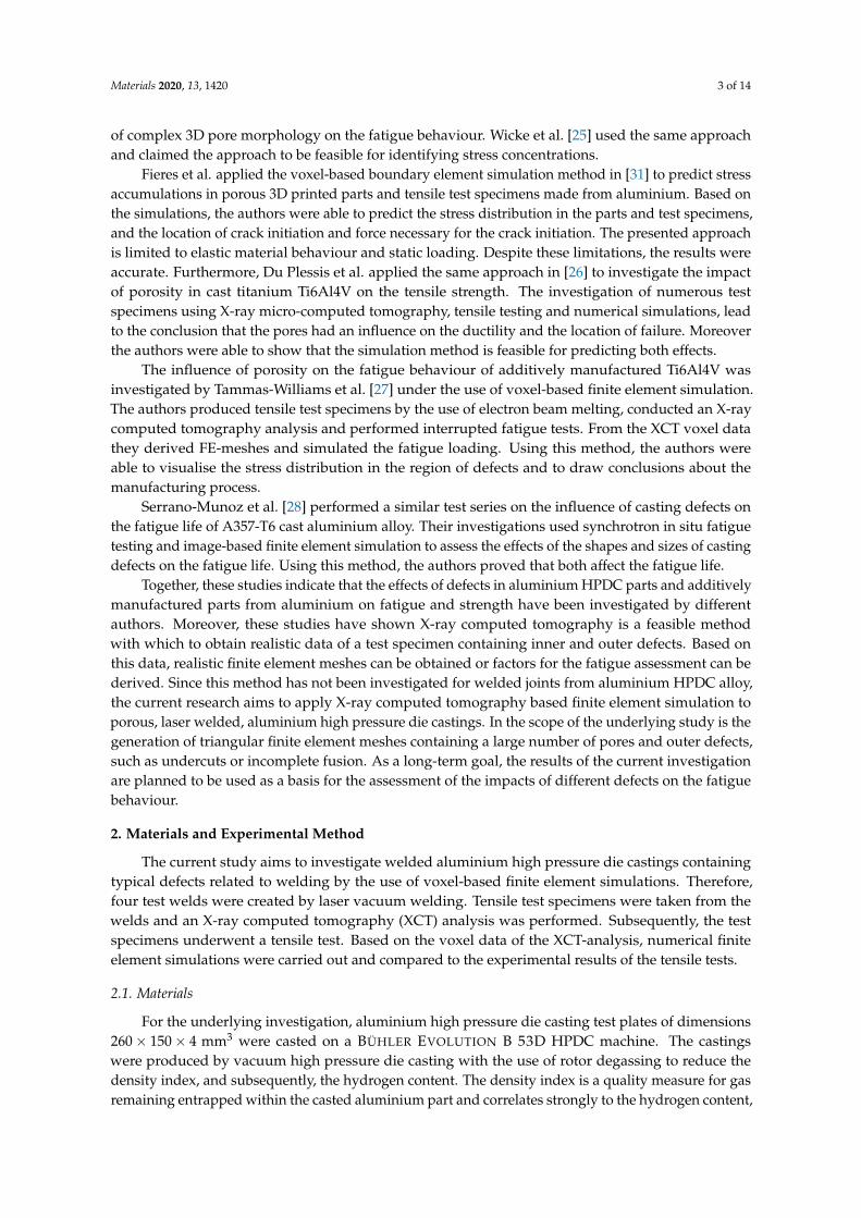
Figure 5 illustrates the outcome of the X-ray computed tomography analysis of the selected weldseams. Herein, the pore diameter is depicted in pseudo colour. As seen in the images, the selectedweldments contain a large variety of typical inner and outer welding defects. Regarding the surfacesof the welds, the specimens A and D have flat and regular surfaces, whereas specimens B and C showirregular weld surfaces; e.g., Figure 5c annotation (3). In addition, specimen B shows two areas ofincomplete fusion; see Figure 5b annotations (1) and (2). In terms of the occurring weld bead porosity,the welds show either a small number of small pores (specimens C and D) or a large number of poresof differing size and pore nests (specimens A and B).
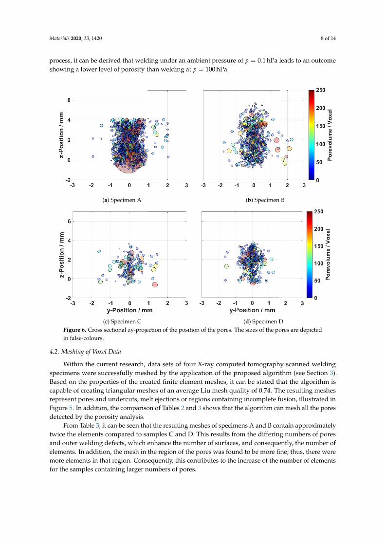
A projection of the position of each pore in the cross sectional view (z-y plane) of the weld isshown in Figure 6. In the diagrams, the sizes of the pores are illustrated in pseudo-colours. In general,
Materials 2020, 13, 1420 7 of 14
the porosity is predominantly located in the centre of the welding in both the z and y-directions. Thus,the highest loss of material occurs in the centre of the welding.
(a) Specimen A (b) Specimen B (c) Specimen C (d) Specimen DFigure 5. Grayscale volume models obtained from X-ray computed tomography showing incompletefusion (1,2) and irregular weld surfaces (3). The pore diameter is depicted in pseudo colour.
Considering an approximated weld bead width of 2 mm, the plots also show pores in the regionnext to the weld bead. These pores are interpreted as base material porosity related to the castingprocess. It is assumed that these pores are a possible explanation for the melt ejections observed inSample B. Welding in the region of casting pores causes a rapid expansion of the entrapped gases andthe displacement of the molten material during the welding process.
Table 2 gives a detailed overview of the detected porosity present in the four investigated samples.This shows that Sample A contains the most and largest pores and the highest average of the cumulativevolume of pores. Specimen B shows a lower number of pores and a lower maximum pore diametercompared to specimen A, and a significantly higher number of pores compared to specimens C and D.The lowest number of pores was present in weld C. Herein, it has to be noted that the load-bearingcross section of the weld is significantly reduced by the irregular surface and root of the weld (seeFigure 8c). Specimen D showed a higher number of pores and a larger cumulative volume of porescompared to Sample C. As it can be seen from the Figures 5 and 6, four welds of differing pore contentsand surface appearances were created by the use of laser vacuum welding. Each combination ofpore content and surface quality were investigated in the following by the procedure introduced inSection 2:
• Sample A: high pore content and regular surface appearance• Sample B: high pore content and irregular surface appearance• Sample C: low pore content and irregular surface appearance• Sample D: low pore content and regular surface appearance
Table 2. Results of the porosity analysis.
Index Specimen A Specimen B Specimen C Specimen D
Number of pores 708 544 148 298Cumulative volume of pores / 103 Voxel 14.9 5.38 1.58 3.13Minimum pore diameter / mm 0.14 0.14 0.15 0.15Maximum pore diameter / mm 4.51 2.60 1.61 2.71Median pore sphericity 0.59 0.59 0.57 0.57
Based on the outcome of the XCT porosity analysis, it can be stated that the continuousCT-scanning method, in combination with the measurement of multiple specimens at the sametime, successfully delivered voxel data sets of sufficient quality. The smallest pore diameter detectedusing the method and the parameters described above was 146 µm. Considering the applied welding
Materials 2020, 13, 1420 8 of 14
process, it can be derived that welding under an ambient pressure of p = 0.1 hPa leads to an outcomeshowing a lower level of porosity than welding at p = 100 hPa.
(a) Specimen A (b) Specimen B
(c) Specimen C (d) Specimen DFigure 6. Cross sectional zy-projection of the position of the pores. The sizes of the pores are depictedin false-colours.
4.2. Meshing of Voxel Data
Within the current research, data sets of four X-ray computed tomography scanned weldingspecimens were successfully meshed by the application of the proposed algorithm (see Section 3).Based on the properties of the created finite element meshes, it can be stated that the algorithm iscapable of creating triangular meshes of an average Liu mesh quality of 0.74. The resulting meshesrepresent pores and undercuts, melt ejections or regions containing incomplete fusion, illustrated inFigure 5. In addition, the comparison of Tables 2 and 3 shows that the algorithm can mesh all the poresdetected by the porosity analysis.
From Table 3, it can be seen that the resulting meshes of specimens A and B contain approximatelytwice the elements compared to samples C and D. This results from the differing numbers of poresand outer welding defects, which enhance the number of surfaces, and consequently, the number ofelements. In addition, the mesh in the region of the pores was found to be more fine; thus, there weremore elements in that region. Consequently, this contributes to the increase of the number of elementsfor the samples containing larger numbers of pores.
Materials 2020, 13, 1420 9 of 14
Table 3. Properties of the created FE-Meshes.
Parameter Specimen A Specimen B Specimen C Specimen D
Number of Nodes 233211 242224 136867 131876Number of Elements 1052983 1069364 581831 567605Meshed Pores 708 544 148 298
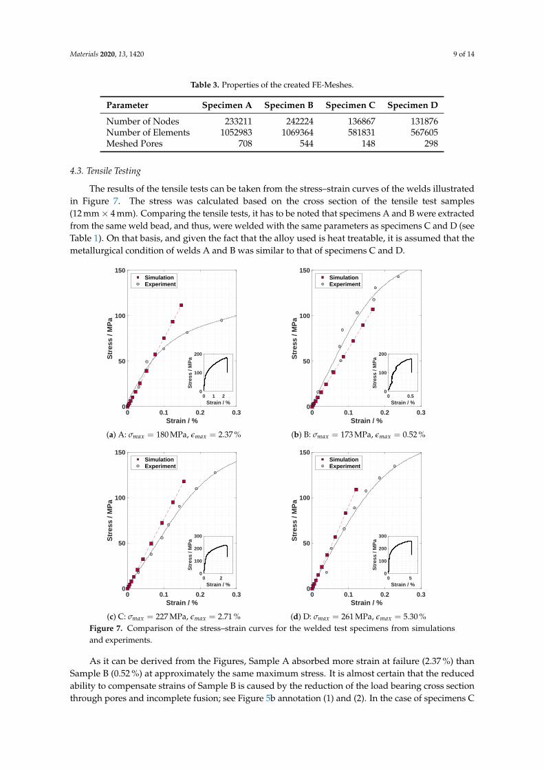
4.3. Tensile Testing
The results of the tensile tests can be taken from the stress–strain curves of the welds illustratedin Figure 7. The stress was calculated based on the cross section of the tensile test samples(12 mm × 4 mm). Comparing the tensile tests, it has to be noted that specimens A and B were extractedfrom the same weld bead, and thus, were welded with the same parameters as specimens C and D (seeTable 1). On that basis, and given the fact that the alloy used is heat treatable, it is assumed that themetallurgical condition of welds A and B was similar to that of specimens C and D.
0 0.1 0.2 0.3Strain / %
0
50
100
150
Str
ess
/ MP
a
SimulationExperiment
0 1 2Strain / %
0
100
200
Str
ess
/ MP
a
(a) A: σmax = 180 MPa, εmax = 2.37 %
0 0.1 0.2 0.3Strain / %
0
50
100
150
Str
ess
/ MP
a
SimulationExperiment
0 0.5Strain / %
0
100
200
Str
ess
/ MP
a
(b) B: σmax = 173 MPa, εmax = 0.52 %
0 0.1 0.2 0.3Strain / %
0
50
100
150
Str
ess
/ MP
a
SimulationExperiment
0 2Strain / %
0
100
200
300
Str
ess
/ MP
a
(c) C: σmax = 227 MPa, εmax = 2.71 %
0 0.1 0.2 0.3Strain / %
0
50
100
150
Str
ess
/ MP
a
SimulationExperiment
0 5Strain / %
0
100
200
300
Str
ess
/ MP
a
(d) D: σmax = 261 MPa, εmax = 5.30 %Figure 7. Comparison of the stress–strain curves for the welded test specimens from simulationsand experiments.
As it can be derived from the Figures, Sample A absorbed more strain at failure (2.37 %) thanSample B (0.52 %) at approximately the same maximum stress. It is almost certain that the reducedability to compensate strains of Sample B is caused by the reduction of the load bearing cross sectionthrough pores and incomplete fusion; see Figure 5b annotation (1) and (2). In the case of specimens C
Materials 2020, 13, 1420 10 of 14
and D it can be seen that specimen C absorbed 2.7 % strain, whereas specimen D absorbed 5.3 % strain.In addition, the ultimate tensile stress of specimen C is 34 MPa below that of specimen D. The observeddiscrepancies can be attributed to the differing appearances of the surfaces and roots of the weld beads.This is attributed to the fact that the porosity is approximately equal in both samples in relation to theirload bearing sections (see Figure 5c,d). Thus, these observations confirm that both outer weld beaddefects and pores have an influence on the strength of the weldment. In the case of the weldmentsdiscussed, an increased pore content (Sample B) had a stronger influence on the maximum stress andmaximum elongation than an irregular surface (Sample C).
Furthermore, the comparison of the welds A and B with the welds C and D represents the generalproblem of the occurrence of large variations in the welding outcome when welding aluminium highpressure die castings. Samples A and B and the samples C and D were both taken from the same weldin the same material at varying positions; see Section 2.2. Despite these comparable circumstances,the welding results display strong variations in terms of appearance (e.g., Figure 5a,b) and mechanicalproperties. Therefore, an integral assessment of the welds, for example, by the use of X-ray computedtomography, is necessary.
4.4. Simulation
The results of the finite element simulations are illustrated in Figures 7 and 8. Figure 7 comparesthe stresses and strains of the simulation and the tensile tests, where the stress is calculated based onthe force applied to the reference node (compare Section 3.2). The plots depicted in Figure 7 show thatthe results of the numerical simulation fit to the experiments in the elastic region. The results revealedthat the method applied is able to describe the material’s elastic response to uniaxial loading for porouswelds (Sample A) with an irregular appearance of weld root and surface (Sample B). As depicted inFigure 7b, welds of an irregular appearance can be described by the use of the applied method. In thecase of specimen A (see Figure 7a), the numerical results deviate from the experimental results whenthe stress exceeds 80 MPa. It seems possible that the heat input during welding caused a local declineof the yield limit, since the alloy used is heat treatable. Consequently, plastic deformation occurs in theexperiments while the simulation still assumes linear elastic behaviour.
Figure 8 shows the von Mises stress distribution within the four test specimens when a force ofF = 3 kN is applied at the reference node. The test samples are depicted in the form of longitudinalcutoffs through the centre of the weld. The pseudo-colours are illustrated from 0 to 120 MPa, where120 MPa is a rough estimation of the base material yield strength at 0.2% in the as-casted condition [42].Consequently, the regions displayed in red are interpreted as plastically deformed.
In all simulated geometries, stress concentrations can be observed in the region of inner andouter welding defects. These results reflect those of Fieres et al. [31], who found stress hot spots inthe region of defects in additively manufactured Ti6Al4V parts; see Section 1. Comparing Figure 8a,bshows that there are more plastically deformed areas in Sample B than in Sample A. As it can be seenfrom the longitudinal cuts, the load bearing cross section in Sample B is reduced more than in SampleA, although there are fewer pores present. This may explain the reduction in maximum stress andelongation observed in the tensile tests; see Figure 7b. This hypothesis is supported by the comparisonof specimens C and D, where Sample C shows larger plastically deformed regions than Sample D and adecrease in maximum stress and elongation. Moreover, it can be seen that the plastic deformation startsin the region of imperfections related to welding. The comparison of the four simulation results showsthat a load of F = 3 kN has a stronger impact on the strongly damaged specimens A, B and C than onthe slightly damaged Sample D. In addition, the simulations have shown that the method applied isstrongly dependent on the voxel size. In the current study, the smallest pore which was detected had adiameter of 146 µm. Defects smaller than approximately four voxels are not implemented in the model.Considering smaller pores, in particular, those smaller than approximately 50 voxels, an accuratedescription of the shape is difficult due to the round shape of the pores and the cornered shape of thevoxels.

Materials 2020, 13, 1420 11 of 14
(a) Specimen A (b) Specimen B
(c) Specimen C (d) Specimen DFigure 8. Results of the FE-simulation of the selected welds under a concentrated load of F = 3 kN;Mises stress shown in pseudo-colour. The welds are presented in the form of longitudinal cuts acrossthe centre of the welds.
5. Conclusions
The current research was undertaken to investigate voxel-based finite element simulation as anapproach to visualising the influence of uniaxial loading on the stress distribution in the region of awelding defect. Therefore, four welding test specimens were created, and were characterised by theapplication of X-ray computed tomography and tensile testing. From the generated XCT voxel datasets, finite element meshes were created by the use of the proposed algorithm, and a structural finiteelement simulation model was created and computed. It was shown that the numerical model is ableto visualise the stress distribution of the four welds of differing, complex geometrical appearances.Good agreement of the global stress and strain relationship between the experiment and simulationwas achieved. It was demonstrated that it is possible to visualise the stress distributions in the regionsof welding defects, such as pores, distorted weld surfaces and roots. In addition, the study showedthat the simulation results fit to the outcome of the tensile testing during elastic material behaviour.Regarding the proposed algorithm, it can be stated that the generated meshes describe the test probegeometry integrally, including inner and outer defects.
Further research will cover the expansion of the created finite element model to predict theelastic-plastic material behaviour under uniaxial loading based on voxel data. Moreover the applicationof the presented method on the basis of XCT scans containing smaller voxels is planned. Further workwill although be carried out on the validation of the strain fields obtained from the simulation by digitalimage correlation. On the basis of the findings of the current research, further work will further focuson the influences of differing defects, such as those investigated in this study, on fatigue behaviour.

Materials 2020, 13, 1420 12 of 14
Author Contributions: conceptualisation, F.T. and J.H.; methodology, F.T. and J.H.; software, F.T. andA.Z.; validation, F.T.; formal analysis, F.T. and A.Z.; investigation, F.T.; resources, K.D.; data curation, F.T.;writing—original draft preparation, F.T.; writing—review and editing, J.H., M.L. and K.D.; visualisation, F.T.;supervision, J.H., M.L. and K.D.; project administration, F.T.; funding acquisition, K.D.
Funding: The current research was partly carried out in the framework of the industrial collective researchprogramme (IGF number 18.156 N). It was supported by the Federal Ministry for Economic Affairs and Energy(BMWi) through the AiF (German Federation of Industrial Research Associations eV) based on a decision taken bythe German Bundestag
Acknowledgments: We acknowledge support by the German Research Foundation and the Open AccessPublication Funds of the Technische Universität Braunschweig
Conflicts of Interest: The authors declare no conflict of interest.
References
1. Lutze, P. Gasgehalt und Schweißeignung von Aluminium-Druckguß. Ph.D. Thesis, Technische UniversitätBraunschweig, Braunschweig, Germany, 1989.
2. Herrmann, C.; Pries, H.; Hartmann, G. Energie- und Ressourceneffiziente Produktion von Aluminiumdruckguss;Springer: Berlin/Heidelberg, Germany, 2013, doi:10.1007/978-3-642-39853-7.
3. DVS—Deutscher Verband für Schweissen und verwandte Verfahren E.V. Richtlinie DVS 0912-2:Metall-Schutzgasschweißen von Stahl—Richtlinie zur Verfahrensdurchführung, Vermeiden von Poren; Ed.;DVS-Verlag:Düsseldorf, February 1991.
4. Wiesner, S. Wirtschaftliche Herstellung von gasarmem, schweißbarem Aluminium-Druckguß. Ph.D. Thesis,Technische Universität Braunschweig, Braunschweig, Germany, 2003.
5. Winkler, R. Porenbildung beim Laserstrahlschweissen von Aluminium-Druckguss. Ph.D. Thesis, UniversitätStuttgart, Stuttgart, Germany, 2004.
6. Dittrich, D.; Standfuß, J.; Jahn, A. Neuartiges Verfahren zum druckdichten Laserstrahlschweißen vonAluminium aus Atmosphären-Druckguss. In Proceedings of the DVS Congress 2016, Leipzig, Germany,19–20 September 2016; Ed.; DVS-Media: Düsseldorf, Germany, 2016; Deutscher Verband für Schweißen undVerwandte Verfahren, DVS-Berichte Band 327; pp. 289–293.
7. Fritzsche, A.; Hilgenberg, K.; Teichmann, F.; Pries, H.; Dilger, K.; Rethmeier, M. Improved degassing inlaser beam welding of aluminum die casting by an electromagnetic field. J. Mater. Process. Technol. 2018,253, 51–56, doi:10.1016/j.jmatprotec.2017.10.021.
8. Teichmann, F.; Müller, S.; Dilger, K. Investigations on dual laser beam welding of aluminum high pressuredie castings at reduced ambient pressure. J. Laser Appl. 2018, 30, 032420, doi:10.2351/1.5040640.
9. Teichmann, F.; Müller, S.; Dilger, K. On the occurrence of weld bead porosity during laser vacuum weldingof high pressure aluminium die castings. Procedia CIRP 2018, 74, 438–441, doi:10.1016/j.procir.2018.08.163.
10. Krahn, O.; Dilger, K. Abschlussbericht S759: Einsatz des Mehrstrahl Elektronenstrahlschweißens für einewirtschaftliche Fertigung von hochwertigen Aluminium-Druckguss-Komponenten; Ed.; Institut für Füge- undSchweißtechnik: Braunschweig, 2008.
11. Teichmann, F.; Pries, H.; Dilger, K. Multiple Spot Electron Beam Welding of Aluminium Die Castings.In Proceedings of the 72nd World Foundry Congress (WFC 2016); Nagoya, Japan, 21–25 May 2016; WorldFoundry Organization, Ed.; Curran Associates Inc.: Red Hook, NY, USA, 2016.
12. Jiang, M.; Tao, W.; Chen, Y. Laser Welding under Vacuum: A Review. Appl. Sci. 2017, 7, 909,doi:10.3390/app7090909.
13. Katayama, S.; Kobayashi, Y.; Mizutani, M.; Matsunawa, A. Effect of vacuum on penetration and defects inlaser welding. J. Laser Appl. 2001, 13, 187, doi:10.2351/1.1404413.
14. Katayama, S.; Abe, Y.; Mizutani, M.; Kawahito, Y. Deep penetration welding with high-power laser undervacuum. Trans. JWRI 2011, 40, 15–19.
15. Börner, C.; Dilger, K.; Rominger, V.; Harrer, T.; Krüssel, T.; Löwer, T. Influence of Ambient Pressure onSpattering and Weld Seam Quality in Laser Beam Welding with the Solid-State Laser. In Proceedings of theICALEO 2011; Laser Institute of America, Ed.; Laser Institute of America: Orlando, FL, USA, 2011; LIA pub,pp. 23–27.
16. Reisgen, U.; Olschok, S.; Jakobs, S.; Turner, C. Laser beam welding under vacuum of high grade materials.Weld. World 2016, 60, 403–413, doi:10.1007/s40194-016-0302-3.
Materials 2020, 13, 1420 13 of 14
17. Luo, Y.; Tang, X.; Lu, F. Experimental study on deep penetrated laser welding under local subatmosphericpressure. Int. J. Adv. Manuf. Technol. 2014, 73, 699–706, doi:10.1007/s00170-014-5870-z.
18. Pang, S.; Chen, X.; Zhou, J.; Shao, X.; Wang, C. 3D transient multiphase model for keyhole, vapor plume, andweld pool dynamics in laser welding including the ambient pressure effect. Opt. Lasers Eng. 2015, 74, 47–58,doi:10.1016/j.optlaseng.2015.05.003.
19. Jiang, M.; Chen, X.; Chen, Y.; Tao, W. Mitigation of porosity defects in fiber laser welding under low vacuum.J. Mater. Process. Technol. 2020, 276, 116385, doi:10.1016/j.jmatprotec.2019.116385.
20. Bossart, P.L.; Martz, H.E.; Brand, H.R.; Hollerbach, K. Application of 3D X-Ray CT Data Sets to Finite ElementAnalysis. In Review of Progress in Quantitative Nondestructive Evaluation; Thompson, D.O., Chimenti, D.E., Eds.;Springer: Boston, MA, USA, 1996; Volume 14, pp. 489–496, doi:10.1007/978-1-4613-0383-1_62.
21. Fang, Q.; Boas, D.A. Tetrahedral mesh generation from volumetric binary and grayscale images.In Proceedings of the 2009 6th IEEE International Symposium on Biomedical Imaging, Boston, MA, USA,June 28–July 1 2009; IEEE: Piscataway, NJ, USA, 2009; pp. 1142–1145, doi:10.1109/ISBI.2009.5193259.
22. Shirani, M.; Härkegård, G. Damage tolerant design of cast components based on defects detected by 3DX-ray computed tomography. Int. J. Fatigue 2012, 41, 188–198, doi:10.1016/j.ijfatigue.2011.09.011.
23. van de Walle, W.; Janssen, H. Validation of a 3D pore scale prediction model for the thermal conductivity ofporous building materials. Energy Procedia 2017, 132, 225–230, doi:10.1016/j.egypro.2017.09.759.
24. Nicoletto, G.; Anzelotti, G.; Konecná, R. X-ray computed tomography vs. metallography for pore sizing andfatigue of cast Al-alloys. Procedia Eng. 2010, 2, 547–554, doi:10.1016/j.proeng.2010.03.059.
25. Wicke, M.; Luetje, M.; Bacaicoa, I.; Brueckner-Foit, A. Characterization of Casting Pores in Fe-rich Al-Si-CuAlloys by Microtomography and Finite Element Analysis. Procedia Struct. Integr. 2016, 2, 2643–2649,doi:10.1016/j.prostr.2016.06.330.
26. Du Plessis, A.; Yadroitsava, I.; Le Roux, S.G.; Yadroitsev, I.; Fieres, J.; Reinhart, C.; Rossouw, P. Prediction ofmechanical performance of Ti6Al4V cast alloy based on microCT-based load simulation. J. Alloy. Compd.2017, 724, 267–274, doi:10.1016/j.jallcom.2017.06.320.
27. Tammas-Williams, S.; Withers, P.J.; Todd, I.; Prangnell, P.B. The Influence of Porosity on FatigueCrack Initiation in Additively Manufactured Titanium Components. Sci. Rep. 2017, 7, 7308,doi:10.1038/s41598-017-06504-5.
28. Serrano-Munoz, I.; Buffiere, J.Y.; Verdu, C. Casting defects in structural components: Are they all dangerous?A 3D study. Int. J. Fatigue 2018, 117, 471–484, doi:10.1016/j.ijfatigue.2018.08.019.
29. Romano, S.; Beretta, S.; Cova, M. Quality control of cast iron: extreme value statistics applied to CTmeasurements. Procedia Struct. Integr. 2017, 7, 275–282, doi:10.1016/j.prostr.2017.11.089.
30. Romano, S.; Brückner-Foit, A.; Brandão, A.; Gumpinger, J.; Ghidini, T.; Beretta, S. Fatigue properties ofAlSi10Mg obtained by additive manufacturing: Defect-based modelling and prediction of fatigue strength.Eng. Fract. Mech. 2018, 187, 165–189, doi:10.1016/j.engfracmech.2017.11.002.
31. Fieres, J.; Schumann, P.; Reinhart, C. Predicting failure in additively manufactured parts using X-raycomputed tomography and simulation. Procedia Eng. 2018, 213, 69–78, doi:10.1016/j.proeng.2018.02.008.
32. BDG—Bundesverband der Deutschen Gießerei-Industrie. P 230: Unterdruck-Dichteprüfung—P 230Bestimmung des Dichte—Index für Aluminiumgusslegierungen; Ed.; BDG - Bundesverband der DeutschenGießerei-Industrie: Düsseldorf, Germany, August 2015.
33. Teichmann, F.; Pries, H.; Müller, S.; Dilger, K. Schlussbericht IGF-Vorhaben 18.156 N (ReduPore): Reduzierung derPorenbildung beim Laserstrahlschweißen von Aluminium- Druckgusslegierungen durch reduzierten Umgebungsdruckund/oder Doppelfokustechnik; Ed.; Institut für Füge- und Schweißtechnik: Braunschweig, 2017.
34. Teichmann, F.; Müller, S.; Pries, H.; Dilger, K. Verringerung der Porenbildung beim Laserstrahlschweißenvon Aluminium-Druckgusslegierungen unter reduziertem Druck und durch Doppelfokustechnik. In Laser-und Elektronenstrahlschweißen von Aluminiumwerkstoffen;DVS Berichte Band 347; Ed.;DVS Media GmbH:Düsseldorf, Germany, 2018.
35. Wadell, H. Volume, Shape, and Roundness of Quartz Particles. J. Geol. 1935, 43, 250–280, doi:10.1086/624298.36. Wevers, M.; Nicolaï, B.; Verboven, P.; Swennen, R.; Roels, S.; Verstrynge, E.; Lomov, S.; Kerckhofs,
G.; van Meerbeek, B.; Mavridou, A.M.; et al. Applications of CT for Non-destructive Testing andMaterials Characterization. In Industrial X-Ray Computed Tomography; Carmignato, S., Dewulf, W.,Leach, R., Eds.; Springer International Publishing: Cham, Switzerland, 2018; Volume 67, pp. 267–331,doi:10.1007/978-3-319-59573-3_8.
Materials 2020, 13, 1420 14 of 14
37. Deutsches Institut für Normung. DIN EN ISO 6892-1: Metallische Werkstoffe – Zugversuch – Teil 1: Prüfverfahrenbei Raumtemperatur; ; Ed.; Beuth Verlag: Berlin, February 2017.
38. Liu, A.; Joe, B. Relationship between tetrahedron shape measures. BIT 1994, 34, 268–287,doi:10.1007/BF01955874.
39. Persson, P.O. Mesh Generation for Implicit Geometries. Ph.D. Thesis, Massachusetts Institute of Technology,Cambridge, MA, USA, 2005.
40. The CGAL Project. CGAL User and Reference Manual, 4.14.1 ed.; CGAL Editorial Board: 2019.41. Si, H. TetGen, a Delaunay-Based Quality Tetrahedral Mesh Generator. ACM Trans. Math. Softw. 2015,
41, 1–36, doi:10.1145/2629697.42. TRIMET Aluminium SE. trimalr-05 Druckgusslegierung für Crashrelevante Anwendungen; Ed.: TRIMET
Aluminium SE, Essen, Germany 2017.43. Ostermann, F. Anwendungstechnologie Aluminium, 3rd ed (online-ausg.) ed.; EBL-Schweitzer; Springer:
Berlin/Heidelberg, Germany, 2015.44. ASM Handbook Committee. ASM Handbook Volume 2—Properties and Selection: Nonferrous Alloys and
Special-Purpose Materials; ASM International: Metals Park, OH, USA, 1992.
© 2020 by the authors. Licensee MDPI, Basel, Switzerland. This article is an open accessarticle distributed under the terms and conditions of the Creative Commons Attribution(CC BY) license (http://creativecommons.org/licenses/by/4.0/).


![Computation of the permeability of porous materials from their microstructure by … · 2013. 1. 21. · images of many porous materials [24, 8]. There is great interest in performing](https://static.fdokument.com/doc/165x107/60aef016c07a5904946638d7/computation-of-the-permeability-of-porous-materials-from-their-microstructure-by.jpg)