Littorina - bauer-modelle.com · 2 Bauer-Modelle, Alleenstraße 31, 73240 Wendlingen, ...
39
Transcript of Littorina - bauer-modelle.com · 2 Bauer-Modelle, Alleenstraße 31, 73240 Wendlingen, ...
Littorina
Best.N
r. 4
.1700
Bauanle
itung
M1:3
2B
auer-
Mo
delle
ww
w.b
auer-
modelle.c
om
, in
fo@
bauer-
modelle.d
e
1 Bauer-Modelle, Alleenstraße 31, 73240 Wendlingen, www.bauer-modelle.com [email protected] Tel. 07024 404 636 No liability for printing errors. Subject to technical changes without notice! 11/2018
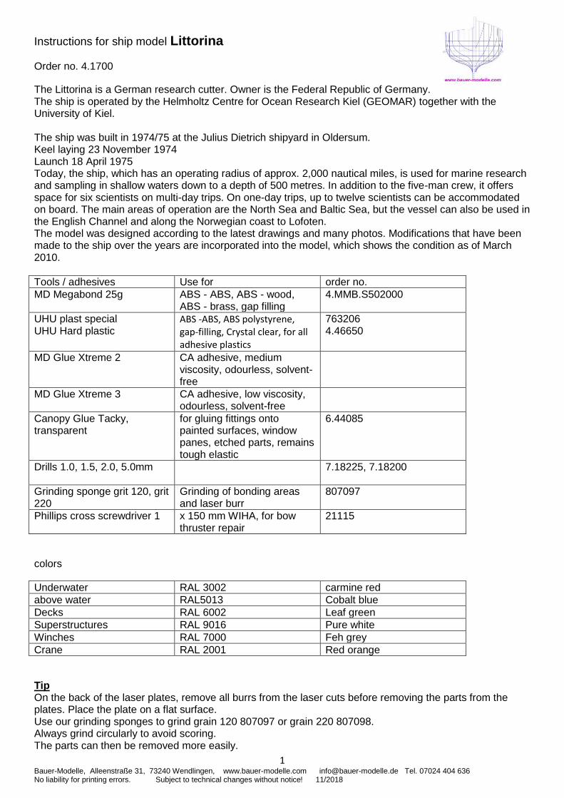
Instructions for ship model Littorina
Order no. 4.1700
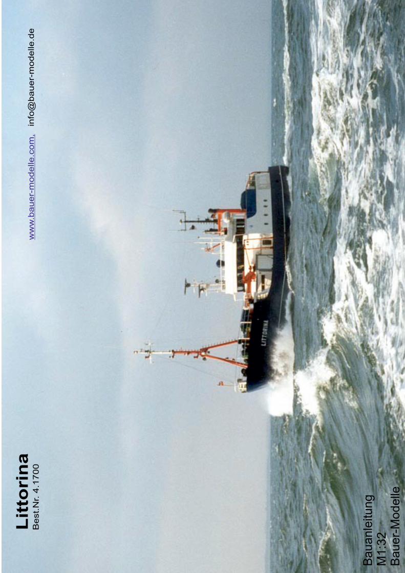
The Littorina is a German research cutter. Owner is the Federal Republic of Germany. The ship is operated by the Helmholtz Centre for Ocean Research Kiel (GEOMAR) together with the University of Kiel. The ship was built in 1974/75 at the Julius Dietrich shipyard in Oldersum. Keel laying 23 November 1974 Launch 18 April 1975 Today, the ship, which has an operating radius of approx. 2,000 nautical miles, is used for marine research and sampling in shallow waters down to a depth of 500 metres. In addition to the five-man crew, it offers space for six scientists on multi-day trips. On one-day trips, up to twelve scientists can be accommodated on board. The main areas of operation are the North Sea and Baltic Sea, but the vessel can also be used in the English Channel and along the Norwegian coast to Lofoten. The model was designed according to the latest drawings and many photos. Modifications that have been made to the ship over the years are incorporated into the model, which shows the condition as of March 2010.
Tools / adhesives Use for order no.
MD Megabond 25g ABS - ABS, ABS - wood, ABS - brass, gap filling
4.MMB.S502000
UHU plast special UHU Hard plastic
ABS -ABS, ABS polystyrene, gap-filling, Crystal clear, for all adhesive plastics
763206 4.46650
MD Glue Xtreme 2 CA adhesive, medium viscosity, odourless, solvent-free
MD Glue Xtreme 3 CA adhesive, low viscosity, odourless, solvent-free
Canopy Glue Tacky, transparent
for gluing fittings onto painted surfaces, window panes, etched parts, remains tough elastic
6.44085
Drills 1.0, 1.5, 2.0, 5.0mm 7.18225, 7.18200
Grinding sponge grit 120, grit 220
Grinding of bonding areas and laser burr
807097
Phillips cross screwdriver 1 x 150 mm WIHA, for bow thruster repair
21115
colors
Underwater RAL 3002 carmine red
above water RAL5013 Cobalt blue
Decks RAL 6002 Leaf green
Superstructures RAL 9016 Pure white
Winches RAL 7000 Feh grey
Crane RAL 2001 Red orange
Tip On the back of the laser plates, remove all burrs from the laser cuts before removing the parts from the plates. Place the plate on a flat surface. Use our grinding sponges to grind grain 120 807097 or grain 220 807098. Always grind circularly to avoid scoring. The parts can then be removed more easily.
2 Bauer-Modelle, Alleenstraße 31, 73240 Wendlingen, www.bauer-modelle.com [email protected] Tel. 07024 404 636 No liability for printing errors. Subject to technical changes without notice! 11/2018
building instruction
Stand
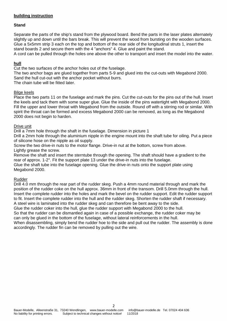
Separate the parts of the ship's stand from the plywood board. Bend the parts in the laser plates alternately slightly up and down until the bars break. This will prevent the wood from bursting on the wooden surfaces. Glue a 5x5mm strip 3 each on the top and bottom of the rear side of the longitudinal struts 1, insert the stand boards 2 and secure them with the 4 "anchors" 4. Glue and paint the stand. A cord can be pulled through the holes one above the other to transport and insert the model into the water. hull Cut the two surfaces of the anchor holes out of the fuselage. The two anchor bags are glued together from parts 5-9 and glued into the cut-outs with Megabond 2000. Sand the hull cut-out with the anchor pocket without burrs. The chain tube will be fitted later. Bilge keels Place the two parts 11 on the fuselage and mark the pins. Cut the cut-outs for the pins out of the hull. Insert the keels and tack them with some super glue. Glue the inside of the pins watertight with Megabond 2000. Fill the upper and lower throat with Megabond from the outside. Round off with a stirring rod or similar. With spirit the throat can be formed and excess Megabond 2000 can be removed, as long as the Megabond 2000 does not begin to harden. Drive unit Drill a 7mm hole through the shaft in the fuselage. Dimension in picture 1 Drill a 2mm hole through the aluminium nipple in the engine mount into the shaft tube for oiling. Put a piece of silicone hose on the nipple as oil supply. Screw the two drive-in nuts to the motor flange. Drive-in nut at the bottom, screw from above. Lightly grease the screw. Remove the shaft and insert the sterntube through the opening. The shaft should have a gradient to the rear of approx. 1-2°. Fit the support plate 13 under the drive-in nuts into the fuselage. Glue the shaft tube into the fuselage opening. Glue the drive-in nuts onto the support plate using Megabond 2000. Rudder Drill 4.0 mm through the rear part of the rudder skeg. Push a 4mm round material through and mark the position of the rudder coke on the hull approx. 36mm in front of the transom. Drill 5.0mm through the hull. Insert the complete rudder into the holes and mark the bevel on the rudder support. Edit the rudder support to fit. Insert the complete rudder into the hull and the rudder skeg. Shorten the rudder shaft if necessary. A steel wire is laminated into the rudder skeg and can therefore be bent away to the side. Glue the rudder coker into the hull, glue the rudder support with Megabond 2000 to the hull. So that the rudder can be dismantled again in case of a possible exchange, the rudder coker may be can only be glued in the bottom of the fuselage, without lateral reinforcements in the hull. When disassembling, simply bend the rudder hoe to the side and pull out the rudder. The assembly is done accordingly. The rudder fin can be removed by pulling out the wire.
3 Bauer-Modelle, Alleenstraße 31, 73240 Wendlingen, www.bauer-modelle.com [email protected] Tel. 07024 404 636 No liability for printing errors. Subject to technical changes without notice! 11/2018
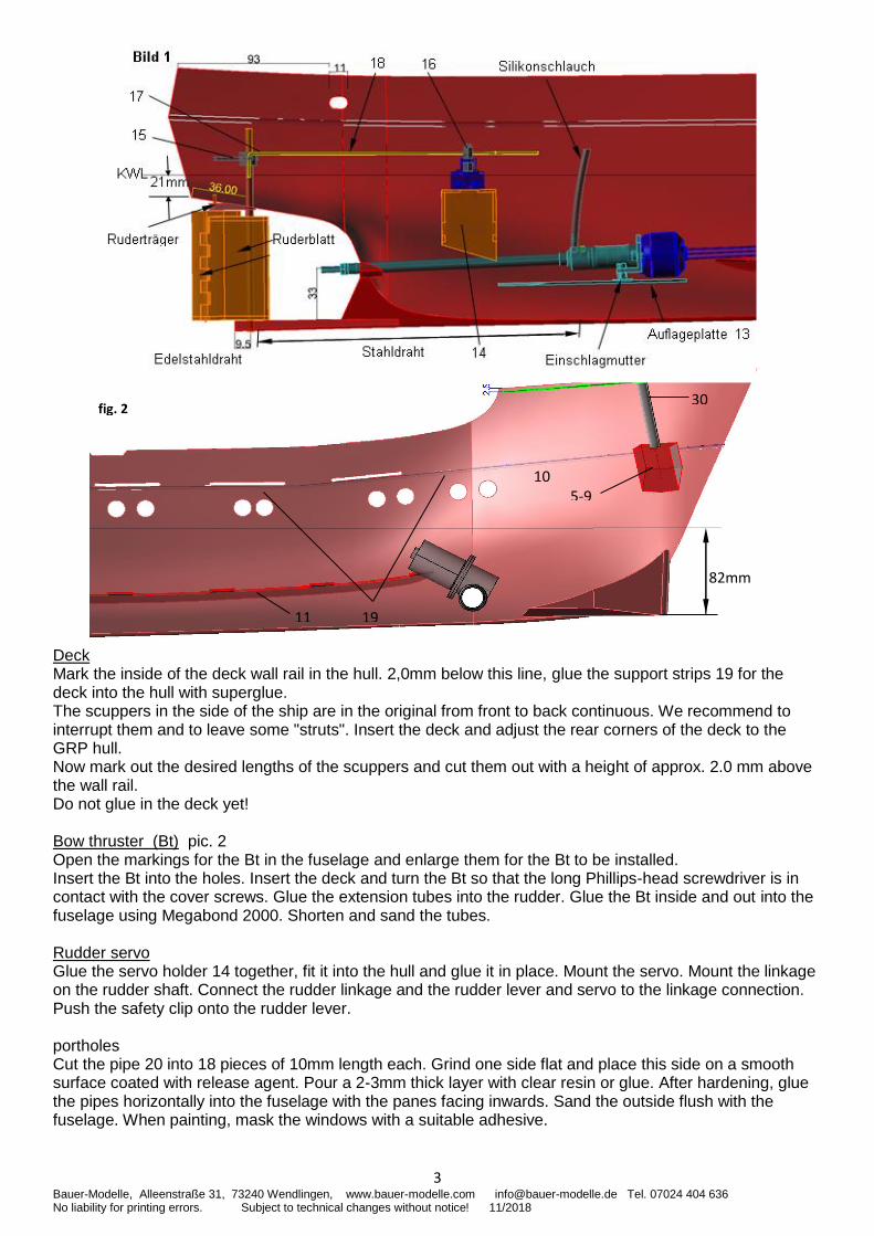
Deck Mark the inside of the deck wall rail in the hull. 2,0mm below this line, glue the support strips 19 for the deck into the hull with superglue. The scuppers in the side of the ship are in the original from front to back continuous. We recommend to interrupt them and to leave some "struts". Insert the deck and adjust the rear corners of the deck to the GRP hull. Now mark out the desired lengths of the scuppers and cut them out with a height of approx. 2.0 mm above the wall rail. Do not glue in the deck yet! Bow thruster (Bt) pic. 2 Open the markings for the Bt in the fuselage and enlarge them for the Bt to be installed. Insert the Bt into the holes. Insert the deck and turn the Bt so that the long Phillips-head screwdriver is in contact with the cover screws. Glue the extension tubes into the rudder. Glue the Bt inside and out into the fuselage using Megabond 2000. Shorten and sand the tubes. Rudder servo Glue the servo holder 14 together, fit it into the hull and glue it in place. Mount the servo. Mount the linkage on the rudder shaft. Connect the rudder linkage and the rudder lever and servo to the linkage connection. Push the safety clip onto the rudder lever. portholes Cut the pipe 20 into 18 pieces of 10mm length each. Grind one side flat and place this side on a smooth surface coated with release agent. Pour a 2-3mm thick layer with clear resin or glue. After hardening, glue the pipes horizontally into the fuselage with the panes facing inwards. Sand the outside flush with the fuselage. When painting, mask the windows with a suitable adhesive.
5-9
19 11
10
30
82mm
fig. 2
4 Bauer-Modelle, Alleenstraße 31, 73240 Wendlingen, www.bauer-modelle.com [email protected] Tel. 07024 404 636 No liability for printing errors. Subject to technical changes without notice! 11/2018
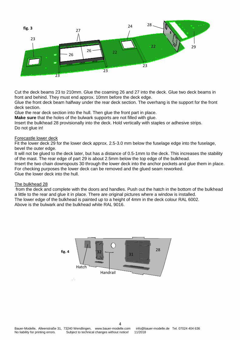
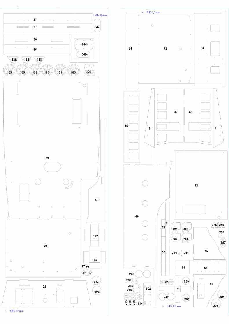
Cut the deck beams 23 to 210mm. Glue the coaming 26 and 27 into the deck. Glue two deck beams in front and behind. They must end approx. 10mm before the deck edge. Glue the front deck beam halfway under the rear deck section. The overhang is the support for the front deck section. Glue the rear deck section into the hull. Then glue the front part in place. Make sure that the holes of the bulwark supports are not filled with glue. Insert the bulkhead 28 provisionally into the deck. Hold vertically with staples or adhesive strips. Do not glue in! Forecastle lower deck Fit the lower deck 29 for the lower deck approx. 2.5-3.0 mm below the fuselage edge into the fuselage, bevel the outer edge. It will not be glued to the deck later, but has a distance of 0.5-1mm to the deck. This increases the stability of the mast. The rear edge of part 29 is about 2.5mm below the top edge of the bulkhead. Insert the two chain downspouts 30 through the lower deck into the anchor pockets and glue them in place. For checking purposes the lower deck can be removed and the glued seam reworked. Glue the lower deck into the hull. The bulkhead 28 from the deck and complete with the doors and handles. Push out the hatch in the bottom of the bulkhead a little to the rear and glue it in place. There are original pictures where a window is installed. The lower edge of the bulkhead is painted up to a height of 4mm in the deck colour RAL 6002. Above is the bulwark and the bulkhead white RAL 9016.
fig. 3
22
22
23
23 23
23
27 24
29
28
26 26
31 32
28
Hatch
Handrail
fig. 4
5 Bauer-Modelle, Alleenstraße 31, 73240 Wendlingen, www.bauer-modelle.com [email protected] Tel. 07024 404 636 No liability for printing errors. Subject to technical changes without notice! 11/2018
fig. 6
35 36
37
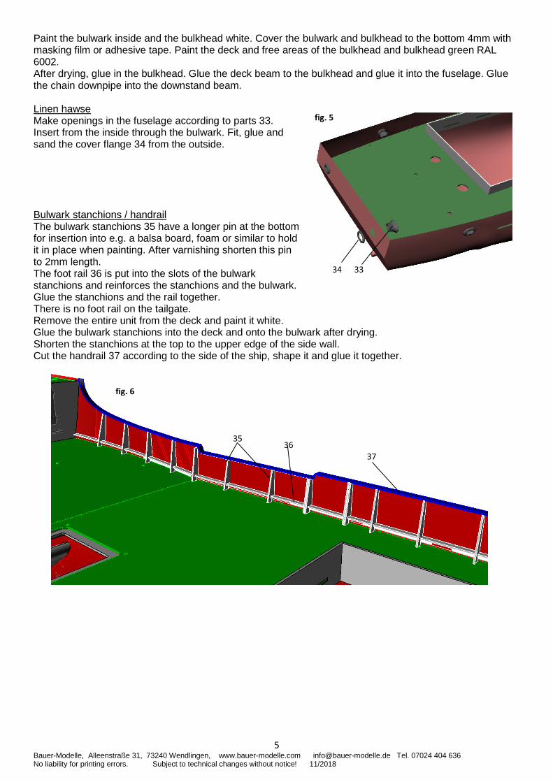
Paint the bulwark inside and the bulkhead white. Cover the bulwark and bulkhead to the bottom 4mm with masking film or adhesive tape. Paint the deck and free areas of the bulkhead and bulkhead green RAL 6002. After drying, glue in the bulkhead. Glue the deck beam to the bulkhead and glue it into the fuselage. Glue the chain downpipe into the downstand beam. Linen hawse Make openings in the fuselage according to parts 33. Insert from the inside through the bulwark. Fit, glue and sand the cover flange 34 from the outside. Bulwark stanchions / handrail The bulwark stanchions 35 have a longer pin at the bottom for insertion into e.g. a balsa board, foam or similar to hold it in place when painting. After varnishing shorten this pin to 2mm length. The foot rail 36 is put into the slots of the bulwark stanchions and reinforces the stanchions and the bulwark. Glue the stanchions and the rail together. There is no foot rail on the tailgate. Remove the entire unit from the deck and paint it white. Glue the bulwark stanchions into the deck and onto the bulwark after drying. Shorten the stanchions at the top to the upper edge of the side wall. Cut the handrail 37 according to the side of the ship, shape it and glue it together.
fig. 5
34 33
6 Bauer-Modelle, Alleenstraße 31, 73240 Wendlingen, www.bauer-modelle.com [email protected] Tel. 07024 404 636 No liability for printing errors. Subject to technical changes without notice! 11/2018
44
43
45
fig. 8
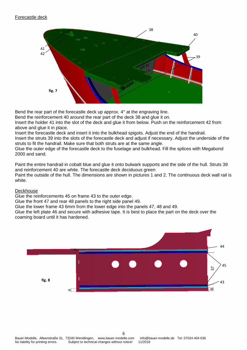
Forecastle deck Bend the rear part of the forecastle deck up approx. 4° at the engraving line. Bend the reinforcement 40 around the rear part of the deck 38 and glue it on. Insert the holder 41 into the slot of the deck and glue it from below. Push on the reinforcement 42 from above and glue it in place. Insert the forecastle deck and insert it into the bulkhead spigots. Adjust the end of the handrail. Insert the struts 39 into the slots of the forecastle deck and adjust if necessary. Adjust the underside of the struts to fit the handrail. Make sure that both struts are at the same angle. Glue the outer edge of the forecastle deck to the fuselage and bulkhead. Fill the splices with Megabond 2000 and sand. Paint the entire handrail in cobalt blue and glue it onto bulwark supports and the side of the hull. Struts 39 and reinforcement 40 are white. The forecastle deck deciduous green Paint the outside of the hull. The dimensions are shown in pictures 1 and 2. The continuous deck wall rail is white. Deckhouse Glue the reinforcements 45 on frame 43 to the outer edge. Glue the front 47 and rear 48 panels to the right side panel 49. Glue the lower frame 43 6mm from the lower edge into the panels 47, 48 and 49. Glue the left plate 46 and secure with adhesive tape. It is best to place the part on the deck over the coaming board until it has hardened.
38
42 41
40
39
fig. 7
7 Bauer-Modelle, Alleenstraße 31, 73240 Wendlingen, www.bauer-modelle.com [email protected] Tel. 07024 404 636 No liability for printing errors. Subject to technical changes without notice! 11/2018
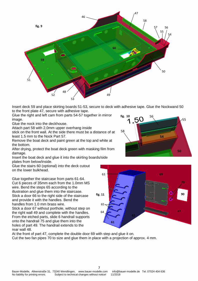
Insert deck 59 and place skirting boards 51-53, secure to deck with adhesive tape. Glue the Nockwand 50 to the front plate 47, secure with adhesive tape. Glue the right and left cam from parts 54-57 together in mirror image. Glue the nock into the deckhouse. Attach part 58 with 2,0mm upper overhang inside stick on the front wall. At the side there must be a distance of at least 1.5 mm to the Nock Part 57. Remove the boat deck and paint green at the top and white at the bottom. After drying, protect the boat deck green with masking film from damage. Insert the boat deck and glue it into the skirting boards/side plates from below/inside. Glue the stairs 60 (optional) into the deck cutout on the lower bulkhead. Glue together the staircase from parts 61-64. Cut 6 pieces of 35mm each from the 1.0mm MS wire. Bend the steps 65 according to the illustration and glue them into the staircase. Stick a door 66 to the right side of the staircase and provide it with the handles. Bend the handles from 1.0 mm brass wire. Stick a door 67 without porthole, without step on the right wall 49 and complete with the handles. From the etched parts, slide 6 handrail supports onto the handrail 75 and glue them into the holes of part 49. The handrail extends to the rear wall 48. At the front of part 47, complete the double door 69 with step and glue it on. Cut the two fan pipes 70 to size and glue them in place with a projection of approx. 4 mm.
52
51
59
48
47
58 46
56
54
49
50
55
53
57
60
fig. 9
58
55
50
56
54
fig. 10
fig. 11
69
62
63
47 64
65
61
90
70
8 Bauer-Modelle, Alleenstraße 31, 73240 Wendlingen, www.bauer-modelle.com [email protected] Tel. 07024 404 636 No liability for printing errors. Subject to technical changes without notice! 11/2018
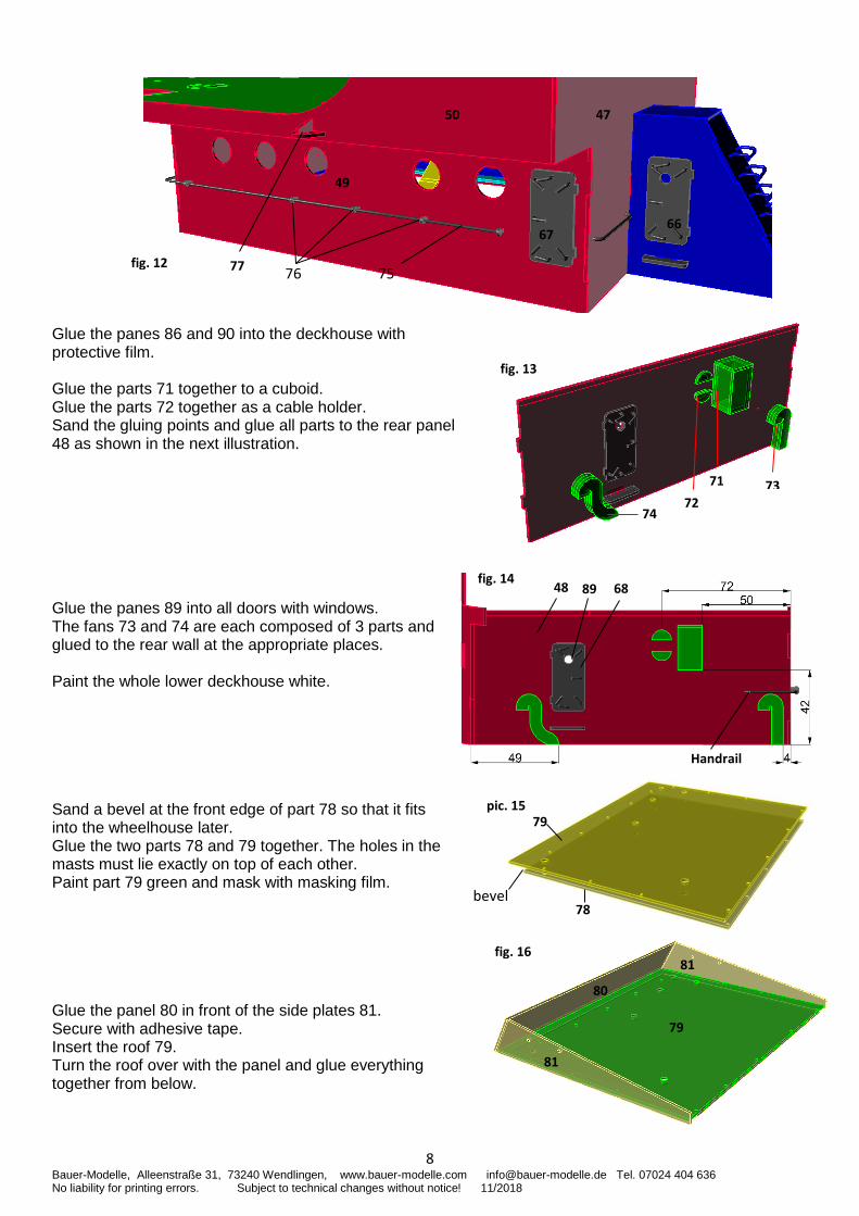
Glue the panes 86 and 90 into the deckhouse with protective film. Glue the parts 71 together to a cuboid. Glue the parts 72 together as a cable holder. Sand the gluing points and glue all parts to the rear panel 48 as shown in the next illustration. Glue the panes 89 into all doors with windows. The fans 73 and 74 are each composed of 3 parts and glued to the rear wall at the appropriate places. Paint the whole lower deckhouse white. Sand a bevel at the front edge of part 78 so that it fits into the wheelhouse later. Glue the two parts 78 and 79 together. The holes in the masts must lie exactly on top of each other. Paint part 79 green and mask with masking film. Glue the panel 80 in front of the side plates 81. Secure with adhesive tape. Insert the roof 79. Turn the roof over with the panel and glue everything together from below.
47
66
49
50
67
77 fig. 12 76 75
71
72 73
74
fig. 13
79
78
pic. 15
bevel
48
Handrail
68 fig. 14
89
81
80
81
fig. 16
79
9 Bauer-Modelle, Alleenstraße 31, 73240 Wendlingen, www.bauer-modelle.com [email protected] Tel. 07024 404 636 No liability for printing errors. Subject to technical changes without notice! 11/2018
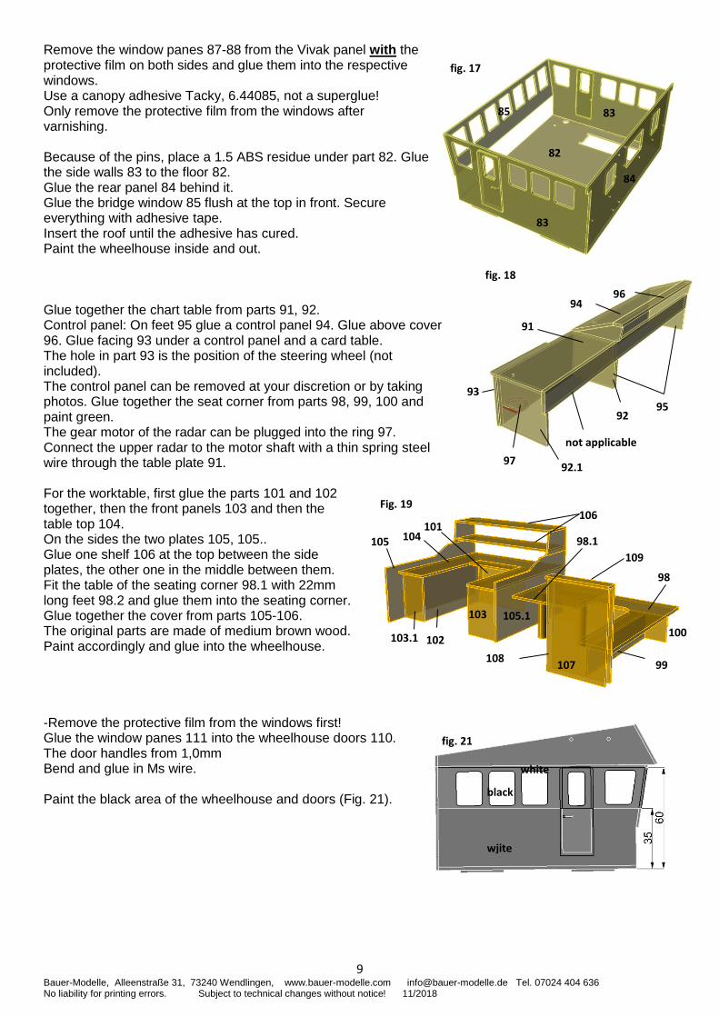
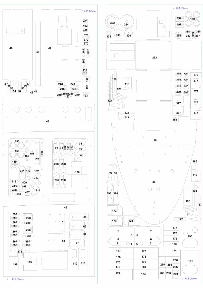
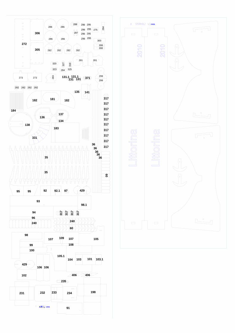
Remove the window panes 87-88 from the Vivak panel with the protective film on both sides and glue them into the respective windows. Use a canopy adhesive Tacky, 6.44085, not a superglue! Only remove the protective film from the windows after varnishing. Because of the pins, place a 1.5 ABS residue under part 82. Glue the side walls 83 to the floor 82. Glue the rear panel 84 behind it. Glue the bridge window 85 flush at the top in front. Secure everything with adhesive tape. Insert the roof until the adhesive has cured. Paint the wheelhouse inside and out. Glue together the chart table from parts 91, 92. Control panel: On feet 95 glue a control panel 94. Glue above cover 96. Glue facing 93 under a control panel and a card table. The hole in part 93 is the position of the steering wheel (not included). The control panel can be removed at your discretion or by taking photos. Glue together the seat corner from parts 98, 99, 100 and paint green. The gear motor of the radar can be plugged into the ring 97. Connect the upper radar to the motor shaft with a thin spring steel wire through the table plate 91. For the worktable, first glue the parts 101 and 102 together, then the front panels 103 and then the table top 104. On the sides the two plates 105, 105.. Glue one shelf 106 at the top between the side plates, the other one in the middle between them. Fit the table of the seating corner 98.1 with 22mm long feet 98.2 and glue them into the seating corner. Glue together the cover from parts 105-106. The original parts are made of medium brown wood. Paint accordingly and glue into the wheelhouse. -Remove the protective film from the windows first! Glue the window panes 111 into the wheelhouse doors 110. The door handles from 1,0mm Bend and glue in Ms wire. Paint the black area of the wheelhouse and doors (Fig. 21).
82
83
84
85 83
fig. 17
93
fig. 18
91
95
92.1
94 96
not applicable
92
97
fig. 21
black
wjite
white
Fig. 19
102
99
100
109
106
104 105
103
98
108 107
101
103.1
105.1
98.1
10 Bauer-Modelle, Alleenstraße 31, 73240 Wendlingen, www.bauer-modelle.com [email protected] Tel. 07024 404 636 No liability for printing errors. Subject to technical changes without notice! 11/2018
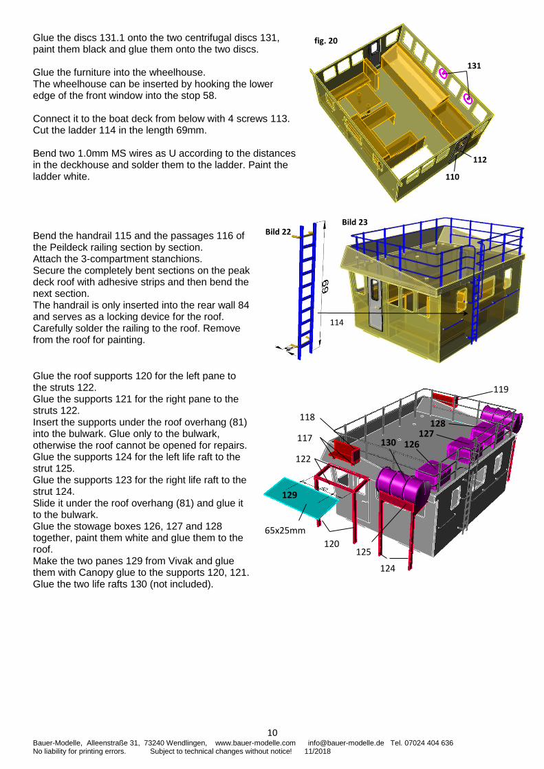
Glue the discs 131.1 onto the two centrifugal discs 131, paint them black and glue them onto the two discs. Glue the furniture into the wheelhouse. The wheelhouse can be inserted by hooking the lower edge of the front window into the stop 58. Connect it to the boat deck from below with 4 screws 113. Cut the ladder 114 in the length 69mm. Bend two 1.0mm MS wires as U according to the distances in the deckhouse and solder them to the ladder. Paint the ladder white.
Bend the handrail 115 and the passages 116 of the Peildeck railing section by section. Attach the 3-compartment stanchions. Secure the completely bent sections on the peak deck roof with adhesive strips and then bend the next section. The handrail is only inserted into the rear wall 84 and serves as a locking device for the roof. Carefully solder the railing to the roof. Remove from the roof for painting. Glue the roof supports 120 for the left pane to the struts 122. Glue the supports 121 for the right pane to the struts 122. Insert the supports under the roof overhang (81) into the bulwark. Glue only to the bulwark, otherwise the roof cannot be opened for repairs. Glue the supports 124 for the left life raft to the strut 125. Glue the supports 123 for the right life raft to the strut 124. Slide it under the roof overhang (81) and glue it to the bulwark. Glue the stowage boxes 126, 127 and 128 together, paint them white and glue them to the roof. Make the two panes 129 from Vivak and glue them with Canopy glue to the supports 120, 121. Glue the two life rafts 130 (not included).
fig. 20
112
110
5
131
5
Bild 23 Bild 22
114
128 127
126 130 117
120
122
118
119
125
129
65x25mm
124
11 Bauer-Modelle, Alleenstraße 31, 73240 Wendlingen, www.bauer-modelle.com [email protected] Tel. 07024 404 636 No liability for printing errors. Subject to technical changes without notice! 11/2018
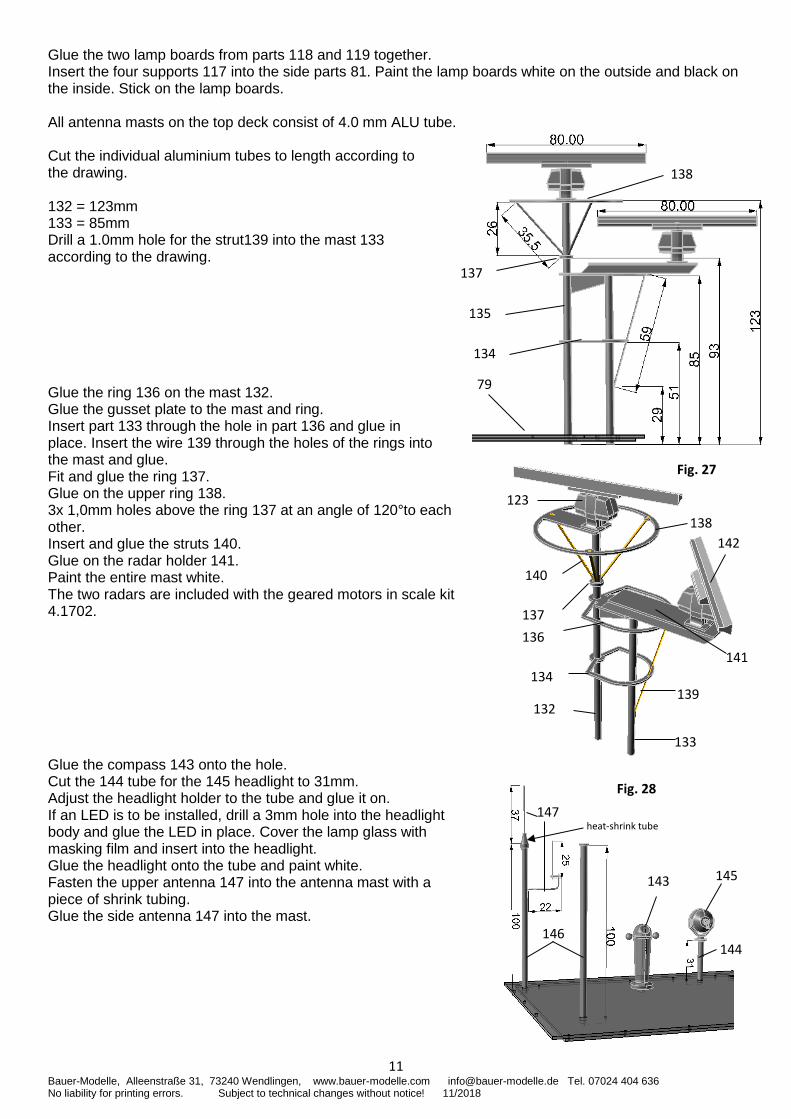
Glue the two lamp boards from parts 118 and 119 together. Insert the four supports 117 into the side parts 81. Paint the lamp boards white on the outside and black on the inside. Stick on the lamp boards. All antenna masts on the top deck consist of 4.0 mm ALU tube. Cut the individual aluminium tubes to length according to the drawing. 132 = 123mm 133 = 85mm Drill a 1.0mm hole for the strut139 into the mast 133 according to the drawing. Glue the ring 136 on the mast 132. Glue the gusset plate to the mast and ring. Insert part 133 through the hole in part 136 and glue in place. Insert the wire 139 through the holes of the rings into the mast and glue. Fit and glue the ring 137. Glue on the upper ring 138. 3x 1,0mm holes above the ring 137 at an angle of 120°to each other. Insert and glue the struts 140. Glue on the radar holder 141. Paint the entire mast white. The two radars are included with the geared motors in scale kit 4.1702. Glue the compass 143 onto the hole. Cut the 144 tube for the 145 headlight to 31mm. Adjust the headlight holder to the tube and glue it on. If an LED is to be installed, drill a 3mm hole into the headlight body and glue the LED in place. Cover the lamp glass with masking film and insert into the headlight. Glue the headlight onto the tube and paint white. Fasten the upper antenna 147 into the antenna mast with a piece of shrink tubing. Glue the side antenna 147 into the mast.
135
134
137
79
138
123
134
133
132
142
137
139
141
138
140
136
Fig. 27
Fig. 28
146
147
143
144
145
heat-shrink tube
12 Bauer-Modelle, Alleenstraße 31, 73240 Wendlingen, www.bauer-modelle.com [email protected] Tel. 07024 404 636 No liability for printing errors. Subject to technical changes without notice! 11/2018
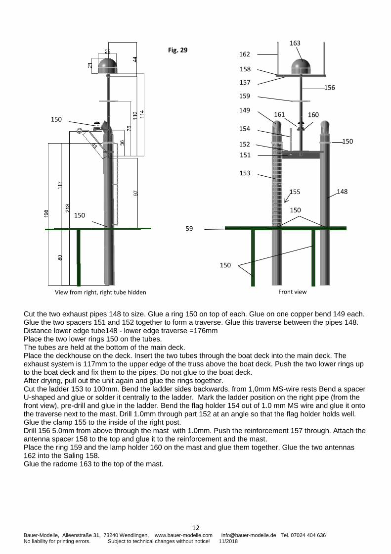
Cut the two exhaust pipes 148 to size. Glue a ring 150 on top of each. Glue on one copper bend 149 each. Glue the two spacers 151 and 152 together to form a traverse. Glue this traverse between the pipes 148. Distance lower edge tube148 - lower edge traverse =176mm Place the two lower rings 150 on the tubes. The tubes are held at the bottom of the main deck. Place the deckhouse on the deck. Insert the two tubes through the boat deck into the main deck. The exhaust system is 117mm to the upper edge of the truss above the boat deck. Push the two lower rings up to the boat deck and fix them to the pipes. Do not glue to the boat deck. After drying, pull out the unit again and glue the rings together. Cut the ladder 153 to 100mm. Bend the ladder sides backwards. from 1,0mm MS-wire rests Bend a spacer U-shaped and glue or solder it centrally to the ladder. Mark the ladder position on the right pipe (from the front view), pre-drill and glue in the ladder. Bend the flag holder 154 out of 1.0 mm MS wire and glue it onto the traverse next to the mast. Drill 1.0mm through part 152 at an angle so that the flag holder holds well. Glue the clamp 155 to the inside of the right post. Drill 156 5.0mm from above through the mast with 1.0mm. Push the reinforcement 157 through. Attach the antenna spacer 158 to the top and glue it to the reinforcement and the mast. Place the ring 159 and the lamp holder 160 on the mast and glue them together. Glue the two antennas 162 into the Saling 158. Glue the radome 163 to the top of the mast.
Fig. 29
150
149 161
156 159
157
158
162
163
160
59
150
153
151
152
150
148
150
150
154
155
Front view View from right, right tube hidden
13 Bauer-Modelle, Alleenstraße 31, 73240 Wendlingen, www.bauer-modelle.com [email protected] Tel. 07024 404 636 No liability for printing errors. Subject to technical changes without notice! 11/2018
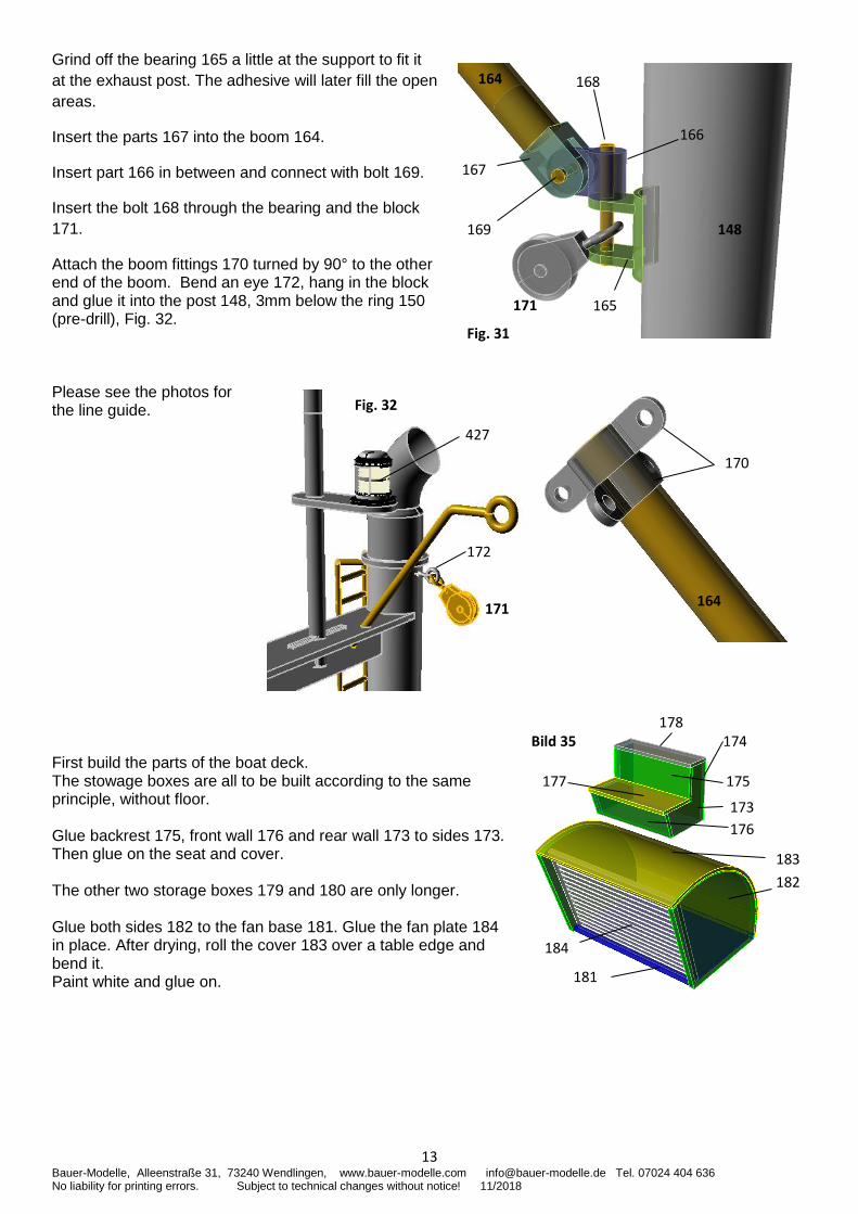
Grind off the bearing 165 a little at the support to fit it
at the exhaust post. The adhesive will later fill the open
areas.
Insert the parts 167 into the boom 164.
Insert part 166 in between and connect with bolt 169.
Insert the bolt 168 through the bearing and the block
171.
Attach the boom fittings 170 turned by 90° to the other end of the boom. Bend an eye 172, hang in the block and glue it into the post 148, 3mm below the ring 150 (pre-drill), Fig. 32. Please see the photos for the line guide. First build the parts of the boat deck. The stowage boxes are all to be built according to the same principle, without floor. Glue backrest 175, front wall 176 and rear wall 173 to sides 173. Then glue on the seat and cover. The other two storage boxes 179 and 180 are only longer. Glue both sides 182 to the fan base 181. Glue the fan plate 184 in place. After drying, roll the cover 183 over a table edge and bend it. Paint white and glue on.
167
166
168
148
165
164
171
169
Fig. 31
172
171
Fig. 32
170
164
427
Bild 35
184
181
182
183
177
174
176
173
178
175
14 Bauer-Modelle, Alleenstraße 31, 73240 Wendlingen, www.bauer-modelle.com [email protected] Tel. 07024 404 636 No liability for printing errors. Subject to technical changes without notice! 11/2018
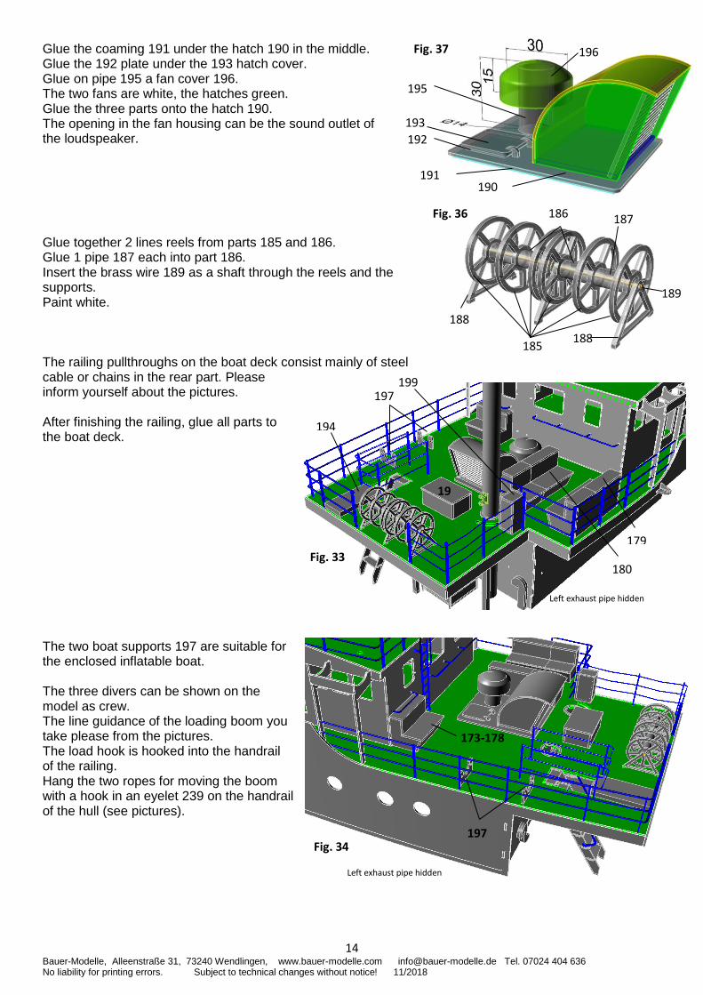
Glue the coaming 191 under the hatch 190 in the middle. Glue the 192 plate under the 193 hatch cover. Glue on pipe 195 a fan cover 196. The two fans are white, the hatches green. Glue the three parts onto the hatch 190. The opening in the fan housing can be the sound outlet of the loudspeaker.
Glue together 2 lines reels from parts 185 and 186. Glue 1 pipe 187 each into part 186. Insert the brass wire 189 as a shaft through the reels and the supports. Paint white. The railing pullthroughs on the boat deck consist mainly of steel cable or chains in the rear part. Please inform yourself about the pictures. After finishing the railing, glue all parts to the boat deck. The two boat supports 197 are suitable for the enclosed inflatable boat. The three divers can be shown on the model as crew. The line guidance of the loading boom you take please from the pictures. The load hook is hooked into the handrail of the railing. Hang the two ropes for moving the boom with a hook in an eyelet 239 on the handrail of the hull (see pictures).
Fig. 37 196
193
192
191 190
195
Fig. 36
188
189
188
186
185
187
Left exhaust pipe hidden
199
19
197
Fig. 33 180
179
194
Fig. 34
173-178
Left exhaust pipe hidden
197
15 Bauer-Modelle, Alleenstraße 31, 73240 Wendlingen, www.bauer-modelle.com [email protected] Tel. 07024 404 636 No liability for printing errors. Subject to technical changes without notice! 11/2018
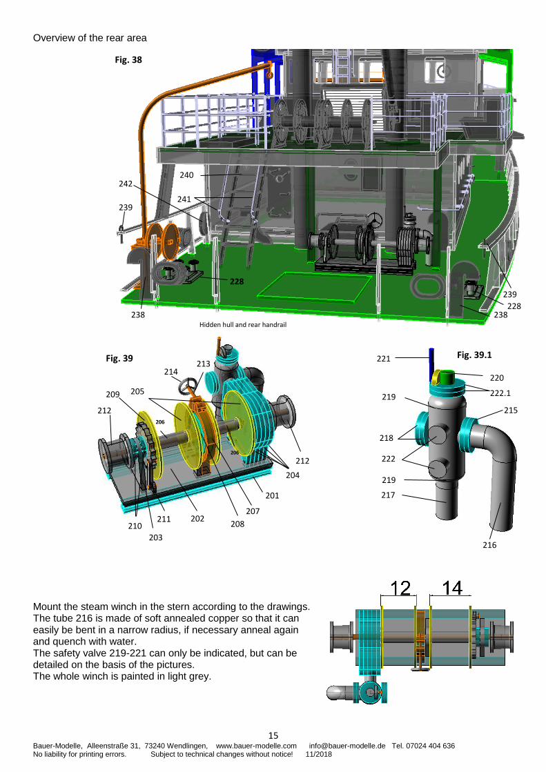
Overview of the rear area Mount the steam winch in the stern according to the drawings. The tube 216 is made of soft annealed copper so that it can easily be bent in a narrow radius, if necessary anneal again and quench with water. The safety valve 219-221 can only be indicated, but can be detailed on the basis of the pictures. The whole winch is painted in light grey.
Fig. 38
Hidden hull and rear handrail
238 238
239
239
240
241
242
228
228
Fig. 39.1
222.1
218
220
219
222
221
219
215
216
214
Fig. 39
201
212
205
203
212
209
204
211 207
208 202
210
206
206
213
217
16 Bauer-Modelle, Alleenstraße 31, 73240 Wendlingen, www.bauer-modelle.com [email protected] Tel. 07024 404 636 No liability for printing errors. Subject to technical changes without notice! 11/2018
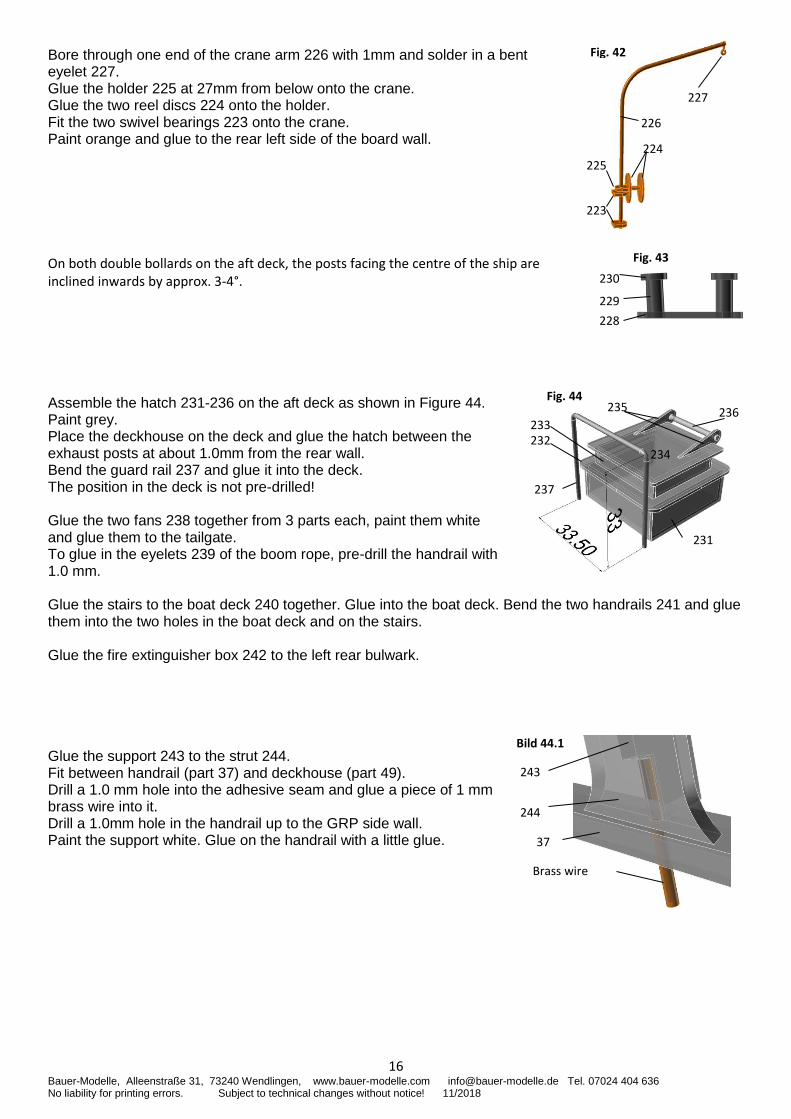
Bore through one end of the crane arm 226 with 1mm and solder in a bent eyelet 227. Glue the holder 225 at 27mm from below onto the crane. Glue the two reel discs 224 onto the holder. Fit the two swivel bearings 223 onto the crane. Paint orange and glue to the rear left side of the board wall. On both double bollards on the aft deck, the posts facing the centre of the ship are inclined inwards by approx. 3-4°. Assemble the hatch 231-236 on the aft deck as shown in Figure 44. Paint grey. Place the deckhouse on the deck and glue the hatch between the exhaust posts at about 1.0mm from the rear wall. Bend the guard rail 237 and glue it into the deck. The position in the deck is not pre-drilled! Glue the two fans 238 together from 3 parts each, paint them white and glue them to the tailgate. To glue in the eyelets 239 of the boom rope, pre-drill the handrail with 1.0 mm. Glue the stairs to the boat deck 240 together. Glue into the boat deck. Bend the two handrails 241 and glue them into the two holes in the boat deck and on the stairs. Glue the fire extinguisher box 242 to the left rear bulwark. Glue the support 243 to the strut 244. Fit between handrail (part 37) and deckhouse (part 49). Drill a 1.0 mm hole into the adhesive seam and glue a piece of 1 mm brass wire into it. Drill a 1.0mm hole in the handrail up to the GRP side wall. Paint the support white. Glue on the handrail with a little glue.
Fig. 42
227
226
224
225
223
Fig. 43
230
229
228
Fig. 44
234
236 233
237
231
235
232
243
Bild 44.1
37
Brass wire
244
17 Bauer-Modelle, Alleenstraße 31, 73240 Wendlingen, www.bauer-modelle.com [email protected] Tel. 07024 404 636 No liability for printing errors. Subject to technical changes without notice! 11/2018
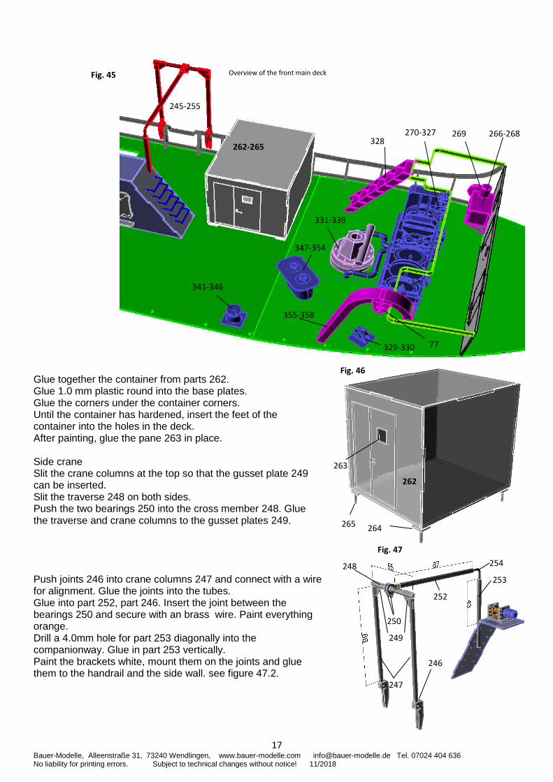
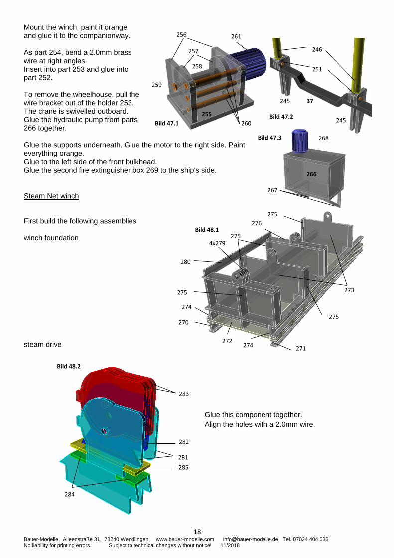
Glue together the container from parts 262. Glue 1.0 mm plastic round into the base plates. Glue the corners under the container corners. Until the container has hardened, insert the feet of the container into the holes in the deck. After painting, glue the pane 263 in place. Side crane Slit the crane columns at the top so that the gusset plate 249 can be inserted. Slit the traverse 248 on both sides. Push the two bearings 250 into the cross member 248. Glue the traverse and crane columns to the gusset plates 249. Push joints 246 into crane columns 247 and connect with a wire for alignment. Glue the joints into the tubes. Glue into part 252, part 246. Insert the joint between the bearings 250 and secure with an brass wire. Paint everything orange. Drill a 4.0mm hole for part 253 diagonally into the companionway. Glue in part 253 vertically. Paint the brackets white, mount them on the joints and glue them to the handrail and the side wall. see figure 47.2.
Fig. 45 Overview of the front main deck
245-255
341-346
262-265
347-354
329-330
331-339
328 270-327 266-268 269
355-358
77
Fig. 46
262
265 264
263
Fig. 47
247
249
254
250
252
253
248
246
18 Bauer-Modelle, Alleenstraße 31, 73240 Wendlingen, www.bauer-modelle.com [email protected] Tel. 07024 404 636 No liability for printing errors. Subject to technical changes without notice! 11/2018
Mount the winch, paint it orange and glue it to the companionway. As part 254, bend a 2.0mm brass wire at right angles. Insert into part 253 and glue into part 252. To remove the wheelhouse, pull the wire bracket out of the holder 253. The crane is swivelled outboard. Glue the hydraulic pump from parts 266 together. Glue the supports underneath. Glue the motor to the right side. Paint everything orange. Glue to the left side of the front bulkhead. Glue the second fire extinguisher box 269 to the ship's side. Steam Net winch
First build the following assemblies winch foundation steam drive
256
255
257
261
258
260
259
Bild 47.1
251
37 245
245
246
Bild 47.2
Bild 47.3 268
266
267
270
271
Bild 48.1
272
273
275
274
4x279
275
274
280
275
275
276
283
Bild 48.2
285
281
282
284
Glue this component together.
Align the holes with a 2.0mm wire.
19 Bauer-Modelle, Alleenstraße 31, 73240 Wendlingen, www.bauer-modelle.com [email protected] Tel. 07024 404 636 No liability for printing errors. Subject to technical changes without notice! 11/2018
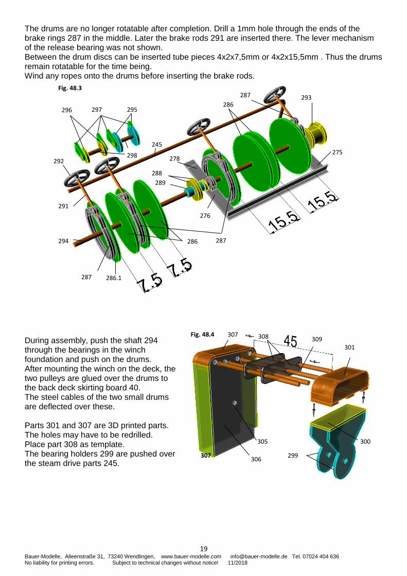
The drums are no longer rotatable after completion. Drill a 1mm hole through the ends of the brake rings 287 in the middle. Later the brake rods 291 are inserted there. The lever mechanism of the release bearing was not shown. Between the drum discs can be inserted tube pieces 4x2x7,5mm or 4x2x15,5mm . Thus the drums remain rotatable for the time being. Wind any ropes onto the drums before inserting the brake rods. During assembly, push the shaft 294 through the bearings in the winch foundation and push on the drums. After mounting the winch on the deck, the two pulleys are glued over the drums to the back deck skirting board 40. The steel cables of the two small drums are deflected over these. Parts 301 and 307 are 3D printed parts. The holes may have to be redrilled. Place part 308 as template. The bearing holders 299 are pushed over the steam drive parts 245.
295
286.1
Fig. 48.3
287
293
297 296
288
289
276
286
291
294
245
292
287
287
278 275 298
286
299
Fig. 48.4
300
307
305
306
309 301
308 307
20 Bauer-Modelle, Alleenstraße 31, 73240 Wendlingen, www.bauer-modelle.com [email protected] Tel. 07024 404 636 No liability for printing errors. Subject to technical changes without notice! 11/2018
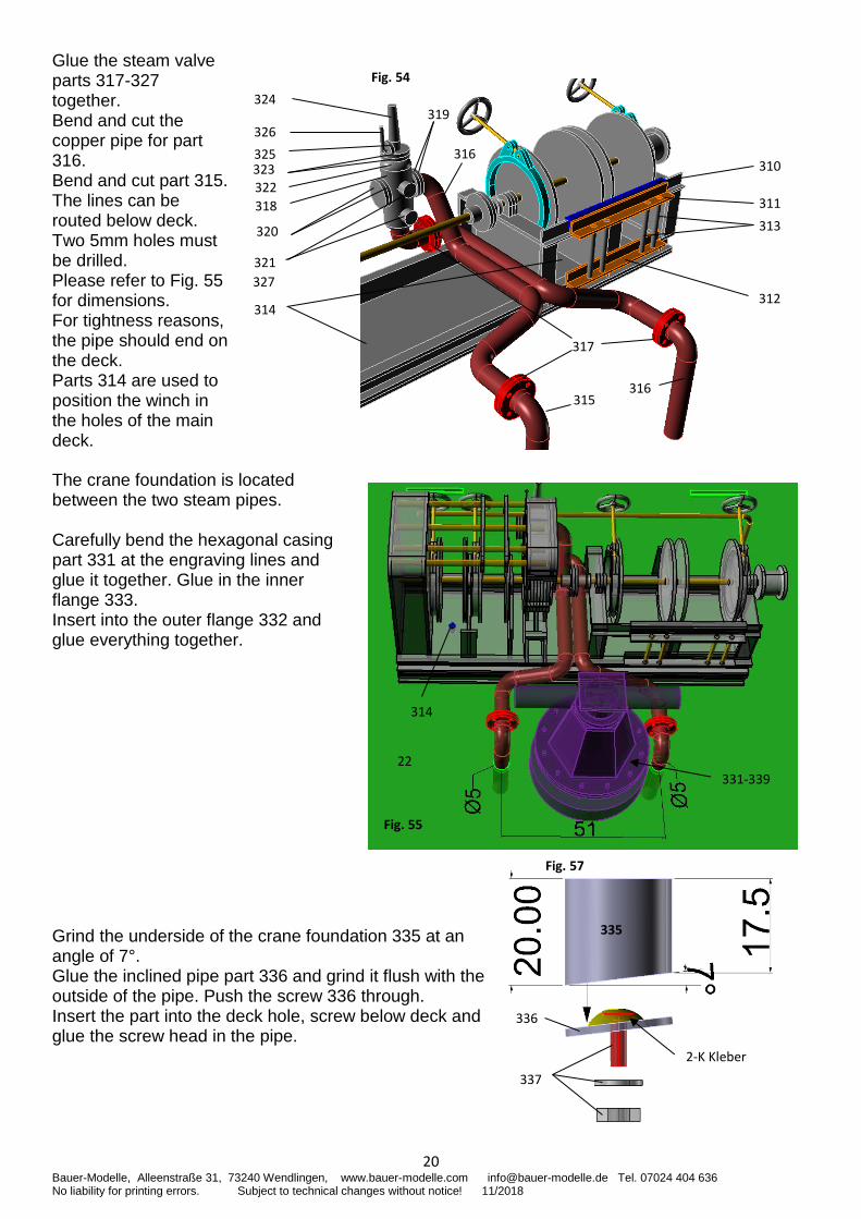
Glue the steam valve parts 317-327 together. Bend and cut the copper pipe for part 316. Bend and cut part 315. The lines can be routed below deck. Two 5mm holes must be drilled. Please refer to Fig. 55 for dimensions. For tightness reasons, the pipe should end on the deck. Parts 314 are used to position the winch in the holes of the main deck.
The crane foundation is located between the two steam pipes. Carefully bend the hexagonal casing part 331 at the engraving lines and glue it together. Glue in the inner flange 333. Insert into the outer flange 332 and glue everything together.
Grind the underside of the crane foundation 335 at an angle of 7°. Glue the inclined pipe part 336 and grind it flush with the outside of the pipe. Push the screw 336 through. Insert the part into the deck hole, screw below deck and glue the screw head in the pipe.
324
326
323
320
321
314
Fig. 54
319
316
325
318
310
311
312
313
317
316
327
322
315
Fig. 55
331-339
22
314
336
335
337
Fig. 57
2-K Kleber
21 Bauer-Modelle, Alleenstraße 31, 73240 Wendlingen, www.bauer-modelle.com [email protected] Tel. 07024 404 636 No liability for printing errors. Subject to technical changes without notice! 11/2018
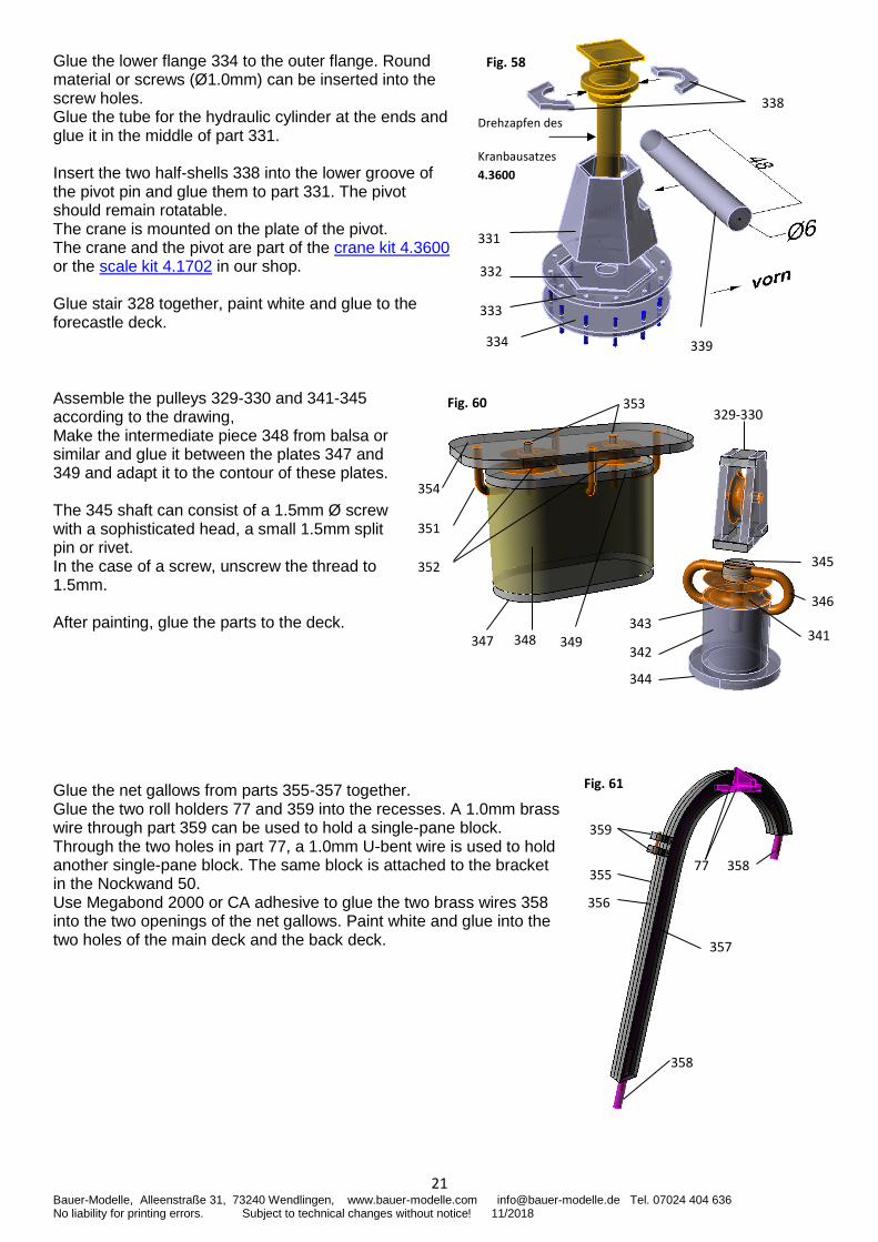
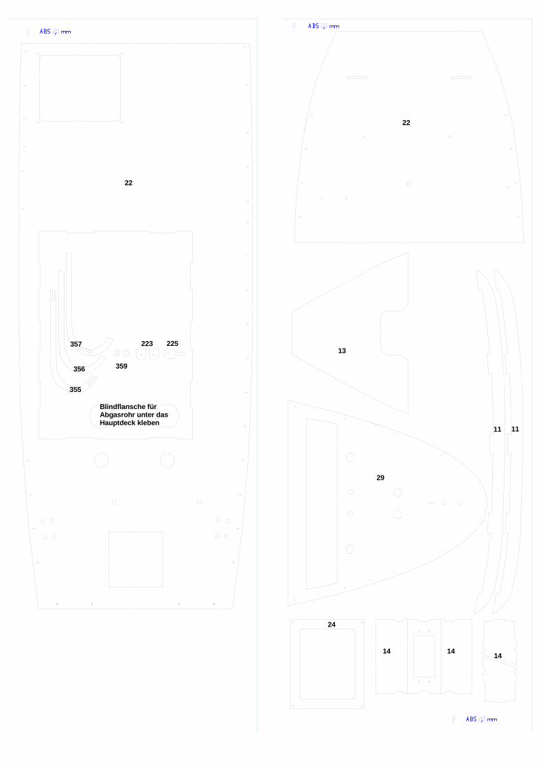
Glue the lower flange 334 to the outer flange. Round material or screws (Ø1.0mm) can be inserted into the screw holes. Glue the tube for the hydraulic cylinder at the ends and glue it in the middle of part 331. Insert the two half-shells 338 into the lower groove of the pivot pin and glue them to part 331. The pivot should remain rotatable. The crane is mounted on the plate of the pivot. The crane and the pivot are part of the crane kit 4.3600 or the scale kit 4.1702 in our shop. Glue stair 328 together, paint white and glue to the forecastle deck. Assemble the pulleys 329-330 and 341-345 according to the drawing, Make the intermediate piece 348 from balsa or similar and glue it between the plates 347 and 349 and adapt it to the contour of these plates. The 345 shaft can consist of a 1.5mm Ø screw with a sophisticated head, a small 1.5mm split pin or rivet. In the case of a screw, unscrew the thread to 1.5mm. After painting, glue the parts to the deck. Glue the net gallows from parts 355-357 together. Glue the two roll holders 77 and 359 into the recesses. A 1.0mm brass wire through part 359 can be used to hold a single-pane block. Through the two holes in part 77, a 1.0mm U-bent wire is used to hold another single-pane block. The same block is attached to the bracket in the Nockwand 50. Use Megabond 2000 or CA adhesive to glue the two brass wires 358 into the two openings of the net gallows. Paint white and glue into the two holes of the main deck and the back deck.
334
333
332
Drehzapfen des
Kranbausatzes
4.3600
331
339
338
Fig. 58
352
351
354
343
346
345
342
329-330
344
341
Fig. 60
347 348 349
353
355
Fig. 61
356
358
357
359
358
77
22 Bauer-Modelle, Alleenstraße 31, 73240 Wendlingen, www.bauer-modelle.com [email protected] Tel. 07024 404 636 No liability for printing errors. Subject to technical changes without notice! 11/2018
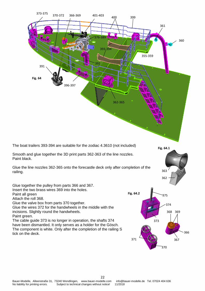
The boat trailers 393-394 are suitable for the zodiac 4.3610 (not included) Smooth and glue together the 3D print parts 362-363 of the line nozzles. Paint black. Glue the line nozzles 362-365 onto the forecastle deck only after completion of the railing. Glue together the pulley from parts 366 and 367. Insert the two brass wires 369 into the holes. Paint all green Attach the roll 368. Glue the valve box from parts 370 together. Glue the wires 372 for the handwheels in the middle with the incisions. Slightly round the handwheels. Paint green. The cable guide 373 is no longer in operation, the shafts 374 have been dismantled. It only serves as a holder for the Gösch. The component is white. Only after the completion of the railing S tick on the deck.
393-394
362-365
376-389
355-359
401-403 400
361
360
370-372
396-397
373-375
Fig. 64
399 366-369
392 391
Fig. 64.1
362
363
369 368
370
367
366
Fig. 64.2 375
371
374
373
23 Bauer-Modelle, Alleenstraße 31, 73240 Wendlingen, www.bauer-modelle.com [email protected] Tel. 07024 404 636 No liability for printing errors. Subject to technical changes without notice! 11/2018
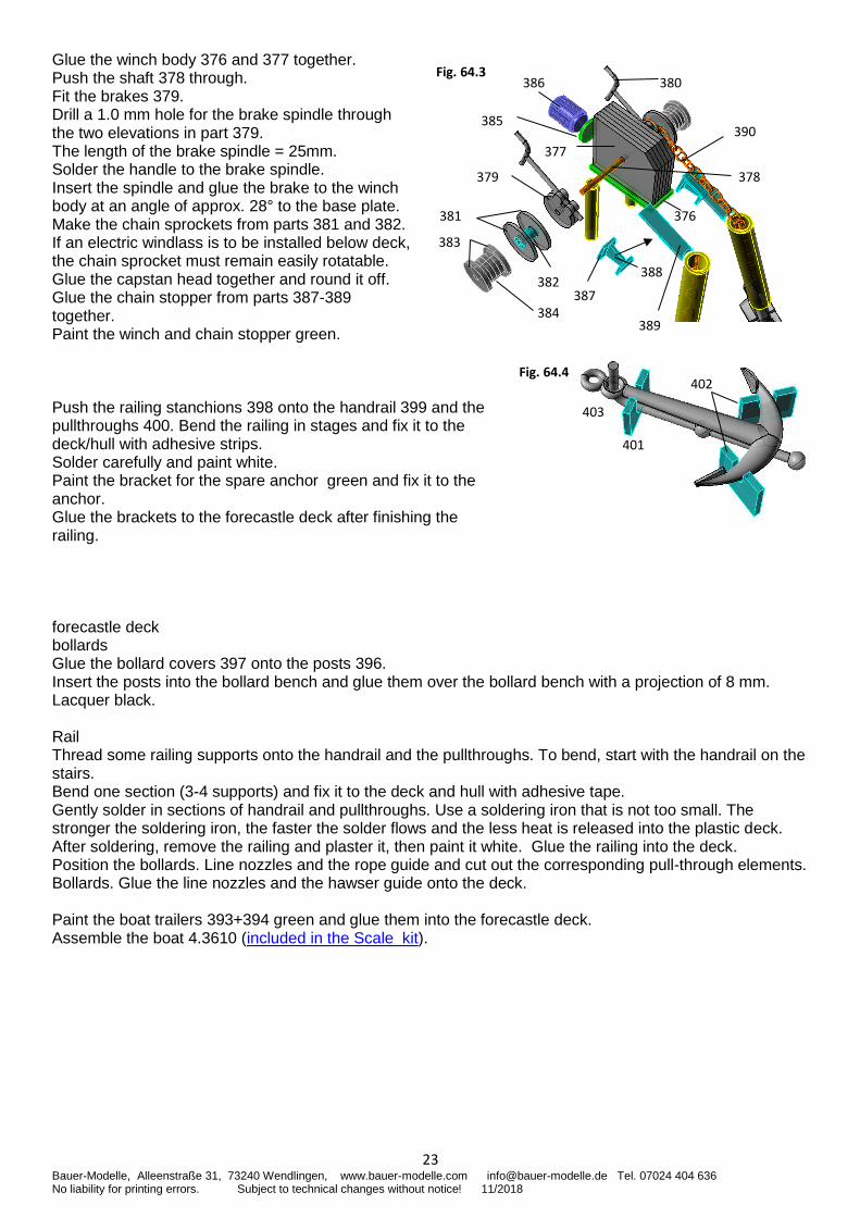
Glue the winch body 376 and 377 together. Push the shaft 378 through. Fit the brakes 379. Drill a 1.0 mm hole for the brake spindle through the two elevations in part 379. The length of the brake spindle = 25mm. Solder the handle to the brake spindle. Insert the spindle and glue the brake to the winch body at an angle of approx. 28° to the base plate. Make the chain sprockets from parts 381 and 382. If an electric windlass is to be installed below deck, the chain sprocket must remain easily rotatable. Glue the capstan head together and round it off. Glue the chain stopper from parts 387-389 together. Paint the winch and chain stopper green. Push the railing stanchions 398 onto the handrail 399 and the pullthroughs 400. Bend the railing in stages and fix it to the deck/hull with adhesive strips. Solder carefully and paint white. Paint the bracket for the spare anchor green and fix it to the anchor. Glue the brackets to the forecastle deck after finishing the railing. forecastle deck bollards Glue the bollard covers 397 onto the posts 396. Insert the posts into the bollard bench and glue them over the bollard bench with a projection of 8 mm. Lacquer black. Rail Thread some railing supports onto the handrail and the pullthroughs. To bend, start with the handrail on the stairs. Bend one section (3-4 supports) and fix it to the deck and hull with adhesive tape. Gently solder in sections of handrail and pullthroughs. Use a soldering iron that is not too small. The stronger the soldering iron, the faster the solder flows and the less heat is released into the plastic deck. After soldering, remove the railing and plaster it, then paint it white. Glue the railing into the deck. Position the bollards. Line nozzles and the rope guide and cut out the corresponding pull-through elements. Bollards. Glue the line nozzles and the hawser guide onto the deck. Paint the boat trailers 393+394 green and glue them into the forecastle deck. Assemble the boat 4.3610 (included in the Scale kit).
Fig. 64.3
385
380
377
386
383
384
376
387
381
382
379
389
378
390
388
402 Fig. 64.4
401
403
24 Bauer-Modelle, Alleenstraße 31, 73240 Wendlingen, www.bauer-modelle.com [email protected] Tel. 07024 404 636 No liability for printing errors. Subject to technical changes without notice! 11/2018
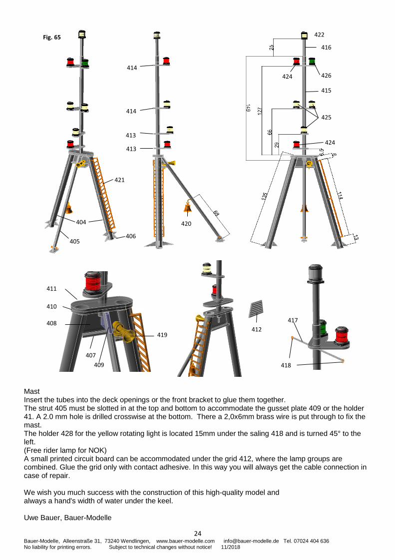
Mast Insert the tubes into the deck openings or the front bracket to glue them together. The strut 405 must be slotted in at the top and bottom to accommodate the gusset plate 409 or the holder 41. A 2.0 mm hole is drilled crosswise at the bottom. There a 2,0x6mm brass wire is put through to fix the mast. The holder 428 for the yellow rotating light is located 15mm under the saling 418 and is turned 45° to the left. (Free rider lamp for NOK) A small printed circuit board can be accommodated under the grid 412, where the lamp groups are combined. Glue the grid only with contact adhesive. In this way you will always get the cable connection in case of repair. We wish you much success with the construction of this high-quality model and always a hand's width of water under the keel. Uwe Bauer, Bauer-Modelle
411
417
418
412
407
408
419
410
409
405
404
406
420
421
413
414
414
413
415
416
422
424
426
Fig. 65
424
425
25 Bauer-Modelle, Alleenstraße 31, 73240 Wendlingen, www.bauer-modelle.com [email protected] Tel. 07024 404 636 No liability for printing errors. Subject to technical changes without notice! 11/2018
Recommended accessories: Order numbers = in the shop www.bauer-modelle.de Battery 7,4V5800mAh Order No. 316645MPX Bowe thruster Order No. 702013 22mm control for bow thruster Order no. 4.4003 6-9,9V, 25A LED 360° all-round emitting 3xred, 2xgreen, 5x white, (deck spotlight not included) Switch module /Sound module USM-RC2 Order no. 4.4200 Sound, switching and light module Loudspeaker order no. 4.4205WS 25W inflatable boat order no. 4.3610 injection moulding set Crane order no. 4.3600 Injection moulding set motor Order No. 4.281575 Low-speed, brushless Controller order no. 4.4100 40A, brushless Servo Order No. 4.5520 BB MD Standard Ship's propeller order no. 716608 (45mm, right, form A) Signal horn order no. 568216 MS, 16mm Bell order no. 568008 8mm Railing supports 3-pass, 2 sets order no. 560395 Etched parts Anchor order no. 562150 Hall anchor width 29mm. Height 50mm Anchor chain order no. 562728 Bar chain 5,3x3,1mm Reserve anchor order no. 562340 Admiralty anchor 40mm single block 8mm order no. 522724 single block 5mm order no. 522722 Load hook order no. 4.5160 MS Search light order no. Radar order no. 4.1705 pieces, with electronics and geared motor Compass column order no. 345 Life raft order no. 606312 39mm Chain for railing order no. 562703 0,3mm glue ABS-ABS , ABS-ABS Order no. 763206, 764642 UHU-Plast special, Ruderer Window panes order no. 6.44085 Tacky GfK Plastic Metal Order No. 763309 stable, Megabond 2000 GfK Plastic Metal, ABS Order No. 1551451-OK MD-Megabond 2000 Superglue medium Order No. 1501102 MD Glue Extreme 2 Trim Lead 4kg Order No. 4.5110 tip Fill the lead balls into servo boxes. Glue them with adhesive tape and fasten them to the floor with Velcro tape. You will need approx. 4 boxes of lead balls. The light LiPo battery can be fixed on the base plate 13 on both sides of the motor. The model is very deep trimmed and lies stable in the water without heeling in curves. With lead battery 7Ah the centre of gravity of the model is approx. 5cm higher. Important safety instructions BAUER-MODELLE cannot monitor compliance with the assembly and operating instructions in connection with the model, nor the installation, operation, use and maintenance of the components associated with the model. Therefore BAUER-MODELLE does not assume any liability for losses, damages or costs resulting from faulty operation, faulty behaviour or in any way connected with the aforementioned. Unless required by law, the obligation of BAUER-MODELLE to pay damages, for whatever reason, including personal injury, death, damage to buildings, as well as damage due to loss of turnover or business, business interruption or other indirect or direct consequential damage resulting from the use of the model, is excluded. Total liability under all circumstances and in all cases is limited to the amount you actually paid for this model. The Littorina model is built and operated solely at the operator's risk. Only careful and thoughtful handling during operation will protect against personal injury and damage to property. Before using the model ship for the first time, check whether your private liability insurance includes the operation of model ships of this type. If necessary, take out special RC model liability insurance. These safety instructions must be kept and passed on to the buyer if the model is resold. The ship model kit is not suitable for children under the age of 14. Before you let the model drive, check it for a safe function of the remote control and the electrical plug connections for a safe and firm connection. Check whether the channel you are using is free. Never drive if you are not sure whether the channel is free. Note that radios or transmitters can interfere strongly with the function of the model. If possible, make sure that none of these devices are operated in the vicinity while you are operating the model. Do not exceed the recommended operating voltage. A higher voltage can destroy the electronics and the model. Care and Maintenance Allow the model to dry out thoroughly after use. Remove any water that has penetrated the model by removing the superstructure. If water has penetrated into the electronics, dry them. Spray the electronics with WET Protect, then it is water-protected (observe instructions).
I am thankful for hints on how to improve the translation. Uwe Bauer, Bauer-Modelle
1
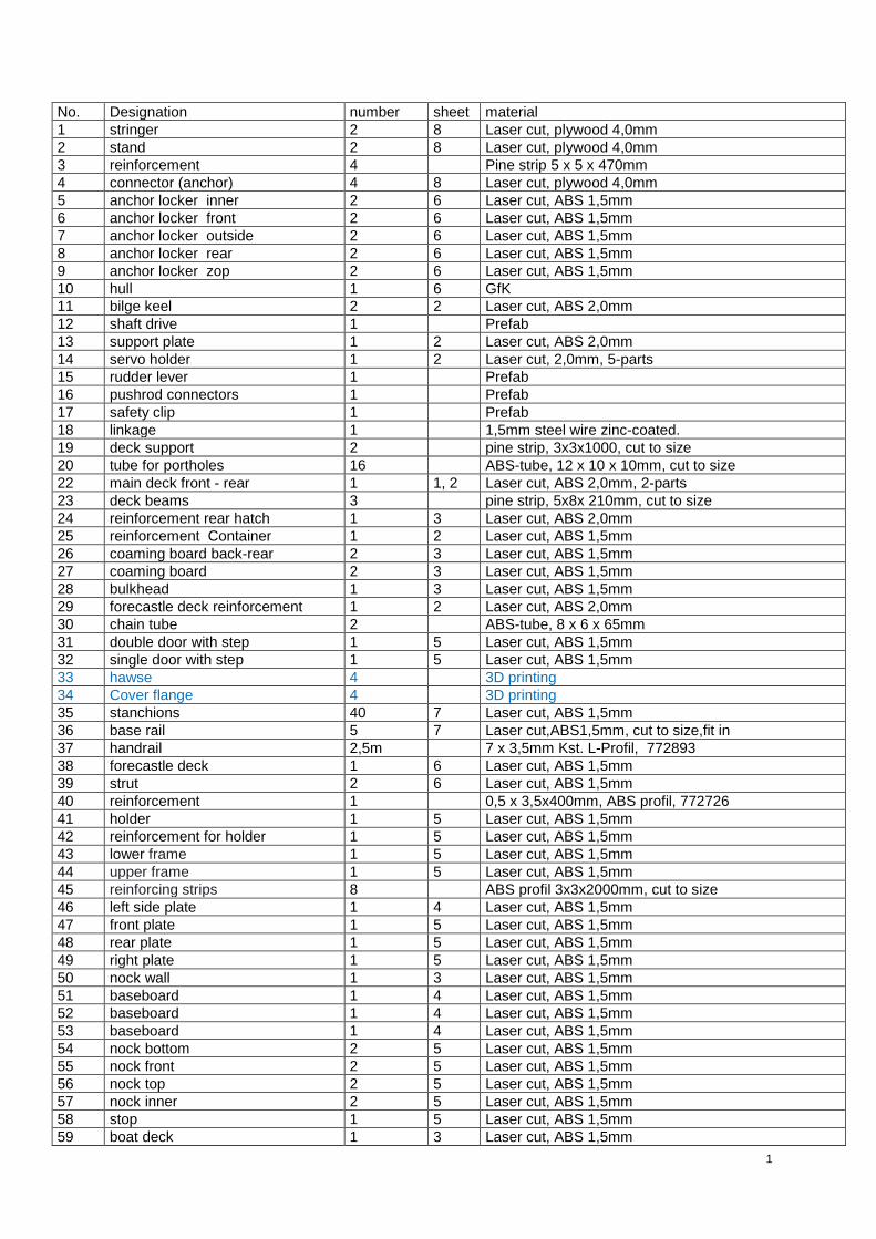
No. Designation number sheet material
1 stringer 2 8 Laser cut, plywood 4,0mm
2 stand 2 8 Laser cut, plywood 4,0mm
3 reinforcement 4 Pine strip 5 x 5 x 470mm
4 connector (anchor) 4 8 Laser cut, plywood 4,0mm
5 anchor locker inner 2 6 Laser cut, ABS 1,5mm
6 anchor locker front 2 6 Laser cut, ABS 1,5mm
7 anchor locker outside 2 6 Laser cut, ABS 1,5mm
8 anchor locker rear 2 6 Laser cut, ABS 1,5mm
9 anchor locker zop 2 6 Laser cut, ABS 1,5mm
10 hull 1 6 GfK
11 bilge keel 2 2 Laser cut, ABS 2,0mm
12 shaft drive 1 Prefab
13 support plate 1 2 Laser cut, ABS 2,0mm
14 servo holder 1 2 Laser cut, 2,0mm, 5-parts
15 rudder lever 1 Prefab
16 pushrod connectors 1 Prefab
17 safety clip 1 Prefab
18 linkage 1 1,5mm steel wire zinc-coated.
19 deck support 2 pine strip, 3x3x1000, cut to size
20 tube for portholes 16 ABS-tube, 12 x 10 x 10mm, cut to size
22 main deck front - rear 1 1, 2 Laser cut, ABS 2,0mm, 2-parts
23 deck beams 3 pine strip, 5x8x 210mm, cut to size
24 reinforcement rear hatch 1 3 Laser cut, ABS 2,0mm
25 reinforcement Container 1 2 Laser cut, ABS 1,5mm
26 coaming board back-rear 2 3 Laser cut, ABS 1,5mm
27 coaming board 2 3 Laser cut, ABS 1,5mm
28 bulkhead 1 3 Laser cut, ABS 1,5mm
29 forecastle deck reinforcement 1 2 Laser cut, ABS 2,0mm
30 chain tube 2 ABS-tube, 8 x 6 x 65mm
31 double door with step 1 5 Laser cut, ABS 1,5mm
32 single door with step 1 5 Laser cut, ABS 1,5mm
33 hawse 4 3D printing
34 Cover flange 4 3D printing
35 stanchions 40 7 Laser cut, ABS 1,5mm
36 base rail 5 7 Laser cut,ABS1,5mm, cut to size,fit in
37 handrail 2,5m 7 x 3,5mm Kst. L-Profil, 772893
38 forecastle deck 1 6 Laser cut, ABS 1,5mm
39 strut 2 6 Laser cut, ABS 1,5mm
40 reinforcement 1 0,5 x 3,5x400mm, ABS profil, 772726
41 holder 1 5 Laser cut, ABS 1,5mm
42 reinforcement for holder 1 5 Laser cut, ABS 1,5mm
43 lower frame 1 5 Laser cut, ABS 1,5mm
44 upper frame 1 5 Laser cut, ABS 1,5mm
45 reinforcing strips 8 ABS profil 3x3x2000mm, cut to size
46 left side plate 1 4 Laser cut, ABS 1,5mm
47 front plate 1 5 Laser cut, ABS 1,5mm
48 rear plate 1 5 Laser cut, ABS 1,5mm
49 right plate 1 5 Laser cut, ABS 1,5mm
50 nock wall 1 3 Laser cut, ABS 1,5mm
51 baseboard 1 4 Laser cut, ABS 1,5mm
52 baseboard 1 4 Laser cut, ABS 1,5mm
53 baseboard 1 4 Laser cut, ABS 1,5mm
54 nock bottom 2 5 Laser cut, ABS 1,5mm
55 nock front 2 5 Laser cut, ABS 1,5mm
56 nock top 2 5 Laser cut, ABS 1,5mm
57 nock inner 2 5 Laser cut, ABS 1,5mm
58 stop 1 5 Laser cut, ABS 1,5mm
59 boat deck 1 3 Laser cut, ABS 1,5mm
2
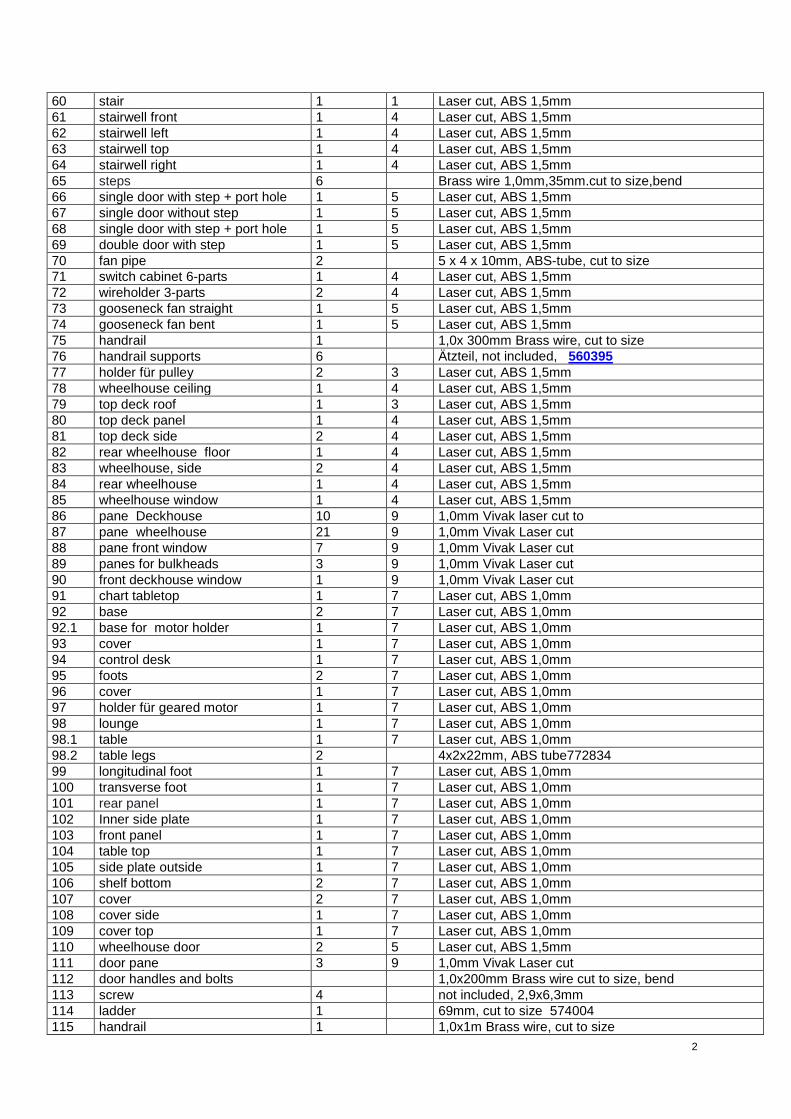
60 stair 1 1 Laser cut, ABS 1,5mm
61 stairwell front 1 4 Laser cut, ABS 1,5mm
62 stairwell left 1 4 Laser cut, ABS 1,5mm
63 stairwell top 1 4 Laser cut, ABS 1,5mm
64 stairwell right 1 4 Laser cut, ABS 1,5mm
65 steps 6 Brass wire 1,0mm,35mm.cut to size,bend
66 single door with step + port hole 1 5 Laser cut, ABS 1,5mm
67 single door without step 1 5 Laser cut, ABS 1,5mm
68 single door with step + port hole 1 5 Laser cut, ABS 1,5mm
69 double door with step 1 5 Laser cut, ABS 1,5mm
70 fan pipe 2 5 x 4 x 10mm, ABS-tube, cut to size
71 switch cabinet 6-parts 1 4 Laser cut, ABS 1,5mm
72 wireholder 3-parts 2 4 Laser cut, ABS 1,5mm
73 gooseneck fan straight 1 5 Laser cut, ABS 1,5mm
74 gooseneck fan bent 1 5 Laser cut, ABS 1,5mm
75 handrail 1 1,0x 300mm Brass wire, cut to size
76 handrail supports 6 Ätzteil, not included, 560395
77 holder für pulley 2 3 Laser cut, ABS 1,5mm
78 wheelhouse ceiling 1 4 Laser cut, ABS 1,5mm
79 top deck roof 1 3 Laser cut, ABS 1,5mm
80 top deck panel 1 4 Laser cut, ABS 1,5mm
81 top deck side 2 4 Laser cut, ABS 1,5mm
82 rear wheelhouse floor 1 4 Laser cut, ABS 1,5mm
83 wheelhouse, side 2 4 Laser cut, ABS 1,5mm
84 rear wheelhouse 1 4 Laser cut, ABS 1,5mm
85 wheelhouse window 1 4 Laser cut, ABS 1,5mm
86 pane Deckhouse 10 9 1,0mm Vivak laser cut to
87 pane wheelhouse 21 9 1,0mm Vivak Laser cut
88 pane front window 7 9 1,0mm Vivak Laser cut
89 panes for bulkheads 3 9 1,0mm Vivak Laser cut
90 front deckhouse window 1 9 1,0mm Vivak Laser cut
91 chart tabletop 1 7 Laser cut, ABS 1,0mm
92 base 2 7 Laser cut, ABS 1,0mm
92.1 base for motor holder 1 7 Laser cut, ABS 1,0mm
93 cover 1 7 Laser cut, ABS 1,0mm
94 control desk 1 7 Laser cut, ABS 1,0mm
95 foots 2 7 Laser cut, ABS 1,0mm
96 cover 1 7 Laser cut, ABS 1,0mm
97 holder für geared motor 1 7 Laser cut, ABS 1,0mm
98 lounge 1 7 Laser cut, ABS 1,0mm
98.1 table 1 7 Laser cut, ABS 1,0mm
98.2 table legs 2 4x2x22mm, ABS tube772834
99 longitudinal foot 1 7 Laser cut, ABS 1,0mm
100 transverse foot 1 7 Laser cut, ABS 1,0mm
101 rear panel 1 7 Laser cut, ABS 1,0mm
102 Inner side plate 1 7 Laser cut, ABS 1,0mm
103 front panel 1 7 Laser cut, ABS 1,0mm
104 table top 1 7 Laser cut, ABS 1,0mm
105 side plate outside 1 7 Laser cut, ABS 1,0mm
106 shelf bottom 2 7 Laser cut, ABS 1,0mm
107 cover 2 7 Laser cut, ABS 1,0mm
108 cover side 1 7 Laser cut, ABS 1,0mm
109 cover top 1 7 Laser cut, ABS 1,0mm
110 wheelhouse door 2 5 Laser cut, ABS 1,5mm
111 door pane 3 9 1,0mm Vivak Laser cut
112 door handles and bolts 1,0x200mm Brass wire cut to size, bend
113 screw 4 not included, 2,9x6,3mm
114 ladder 1 69mm, cut to size 574004
115 handrail 1 1,0x1m Brass wire, cut to size
3
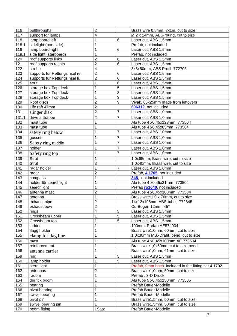
116 pullthroughs 2 Brass wire 0,8mm, 2x1m, cut to size
117 support for lamps 4 Ø 2 x 14mm, ABS-round, cut to size
118 lamp board left 1 6 Laser cut, ABS 1,5mm
118.1 sidelight (port side) 1 Prefab, not included
119 lamp board right 1 6 Laser cut, ABS 1,5mm
119.1 side light (starboard) 1 Prefab, not included
120 roof supports links 2 6 Laser cut, ABS 1,5mm
121 roof supports rechts 2 6 Laser cut, ABS 1,5mm
122 strebe 4 3x3x50mm, ABS Profil 772705
123 supports für Rettungsinsel re. 2 6 Laser cut, ABS 1,5mm
124 supports für Rettungsinsel li. 2 6 Laser cut, ABS 1,5mm
125 strut 1 6 Laser cut, ABS 1,5mm
126 storage box Top deck 1 5 Laser cut, ABS 1,5mm
127 storage box Top deck 1 3 Laser cut, ABS 1,5mm
128 storage box Top deck 1 3 Laser cut, ABS 1,5mm
129 Roof discs 2 9 Vivak, 65x25mm made from leftovers
130 Life raft 47mm 2 606312, not included
131 slinger disk 2 7 Laser cut, ABS 1,0mm
131.1 drive atttrappe 2 7 Laser cut, ABS 1,0mm
132 mast tube 1 Alu tube 4 x0,45x123mm 773504
133 mast tube 1 Alu tube 4 x0,45x85mm 773504
134 safety ring below 1 7 Laser cut, ABS 1,0mm
135 gusset 1 7 Laser cut, ABS 1,0mm
136 Safety ring middle 1 7 Laser cut, ABS 1,0mm
137 holder 1 7 Laser cut, ABS 1,0mm
138 Safety ring top 1 7 Laser cut, ABS 1,0mm
139 Strut 1 1,0x65mm, Brass wire, cut to size
140 Strut 3 1,0x40mm, Brass wire, cut to size
141 radar holder 1 7 Laser cut, ABS 1,0mm
142 radar 2 Prefab, 4.1705, not included
143 compass 1 345, not included
144 holder für searchlight 1 Alu tube 4 x0,45x31mm 773504
145 searchlight 1 Prefab ro1640, not included
146 antenna mast 2 Alu tube 4 x0,45x100mm 773504
147 antenna 1 Brass wire 1,0 x 70mm, cut to size
148 exhaust pipe 2 14x12x198mm ABS-tube, 772845
149 exhaust bow 2 Cu-Bogen 12mm, 45°
150 rings 4 5 Laser cut, ABS 1,5mm
151 Crossbeam upper 1 5 Laser cut, ABS 1,5mm
152 Crossbeam top 1 5 Laser cut, ABS 1,5mm
153 ladder 1 100mm, Prefab AE574004
154 flagg holder 1 Brass wire1,0mm, 60mm, cut to size
155 clamp for flag line 1 1,0x30mm MS.-Draht, bend, cut to size
156 mast 1 Alu tube 4 x0,45x100mm AE 773504
157 reinforcement 1 Brass wire1,0x60mm,cut to size,bend
158 antenna carrier 1 Brass wire1,0mm, 61mm, cut to size
159 ring 1 5 Laser cut, ABS 1,5mm
160 lamp holder 1 5 Laser cut, ABS 1,5mm
161 stern light 1 Prefab, 9mm hoch included in the fitting set 4.1702
162 antennas 2 Brass wire1,0mm, 50mm, cut to size
163 radom 1 Prefab , 3-D Druck
164 derrick boom 1 Alu tube 5 x0,45x150mm 773505
165 bearing 1 Prefab Bauer-Modelle
166 pivot bearing 1 Prefab Bauer-Modelle
167 swivel bearing 1 Prefab Bauer-Modelle
168 pivot pin 1 Brass wire1,5mm, 50mm, cut to size
169 swivel bearing pin 1 Brass wire1,5mm, 50mm, cut to size
170 beem fitting 1Satz Prefab Bauer-Modelle
4
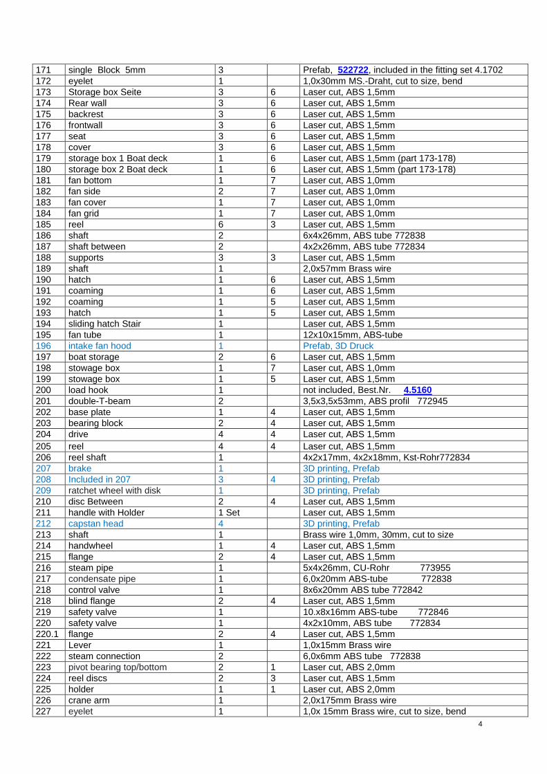
171 single Block 5mm 3 Prefab, 522722, included in the fitting set 4.1702
172 eyelet 1 1,0x30mm MS.-Draht, cut to size, bend
173 Storage box Seite 3 6 Laser cut, ABS 1,5mm
174 Rear wall 3 6 Laser cut, ABS 1,5mm
175 backrest 3 6 Laser cut, ABS 1,5mm
176 frontwall 3 6 Laser cut, ABS 1,5mm
177 seat 3 6 Laser cut, ABS 1,5mm
178 cover 3 6 Laser cut, ABS 1,5mm
179 storage box 1 Boat deck 1 6 Laser cut, ABS 1,5mm (part 173-178)
180 storage box 2 Boat deck 1 6 Laser cut, ABS 1,5mm (part 173-178)
181 fan bottom 1 7 Laser cut, ABS 1,0mm
182 fan side 2 7 Laser cut, ABS 1,0mm
183 fan cover 1 7 Laser cut, ABS 1,0mm
184 fan grid 1 7 Laser cut, ABS 1,0mm
185 reel 6 3 Laser cut, ABS 1,5mm
186 shaft 2 6x4x26mm, ABS tube 772838
187 shaft between 2 4x2x26mm, ABS tube 772834
188 supports 3 3 Laser cut, ABS 1,5mm
189 shaft 1 2,0x57mm Brass wire
190 hatch 1 6 Laser cut, ABS 1,5mm
191 coaming 1 6 Laser cut, ABS 1,5mm
192 coaming 1 5 Laser cut, ABS 1,5mm
193 hatch 1 5 Laser cut, ABS 1,5mm
194 sliding hatch Stair 1 Laser cut, ABS 1,5mm
195 fan tube 1 12x10x15mm, ABS-tube
196 intake fan hood 1 Prefab, 3D Druck
197 boat storage 2 6 Laser cut, ABS 1,5mm
198 stowage box 1 7 Laser cut, ABS 1,0mm
199 stowage box 1 5 Laser cut, ABS 1,5mm
200 load hook 1 not included, Best.Nr. 4.5160
201 double-T-beam 2 3,5x3,5x53mm, ABS profil 772945
202 base plate 1 4 Laser cut, ABS 1,5mm
203 bearing block 2 4 Laser cut, ABS 1,5mm
204 drive 4 4 Laser cut, ABS 1,5mm
205 reel 4 4 Laser cut, ABS 1,5mm
206 reel shaft 1 4x2x17mm, 4x2x18mm, Kst-Rohr772834
207 brake 1 3D printing, Prefab
208 Included in 207 3 4 3D printing, Prefab
209 ratchet wheel with disk 1 3D printing, Prefab
210 disc Between 2 4 Laser cut, ABS 1,5mm
211 handle with Holder 1 Set Laser cut, ABS 1,5mm
212 capstan head 4 3D printing, Prefab
213 shaft 1 Brass wire 1,0mm, 30mm, cut to size
214 handwheel 1 4 Laser cut, ABS 1,5mm
215 flange 2 4 Laser cut, ABS 1,5mm
216 steam pipe 1 5x4x26mm, CU-Rohr 773955
217 condensate pipe 1 6,0x20mm ABS-tube 772838
218 control valve 1 8x6x20mm ABS tube 772842
218 blind flange 2 4 Laser cut, ABS 1,5mm
219 safety valve 1 10.x8x16mm ABS-tube 772846
220 safety valve 1 4x2x10mm, ABS tube 772834
220.1 flange 2 4 Laser cut, ABS 1,5mm
221 Lever 1 1,0x15mm Brass wire
222 steam connection 2 6,0x6mm ABS tube 772838
223 pivot bearing top/bottom 2 1 Laser cut, ABS 2,0mm
224 reel discs 2 3 Laser cut, ABS 1,5mm
225 holder 1 1 Laser cut, ABS 2,0mm
226 crane arm 1 2,0x175mm Brass wire
227 eyelet 1 1,0x 15mm Brass wire, cut to size, bend
5
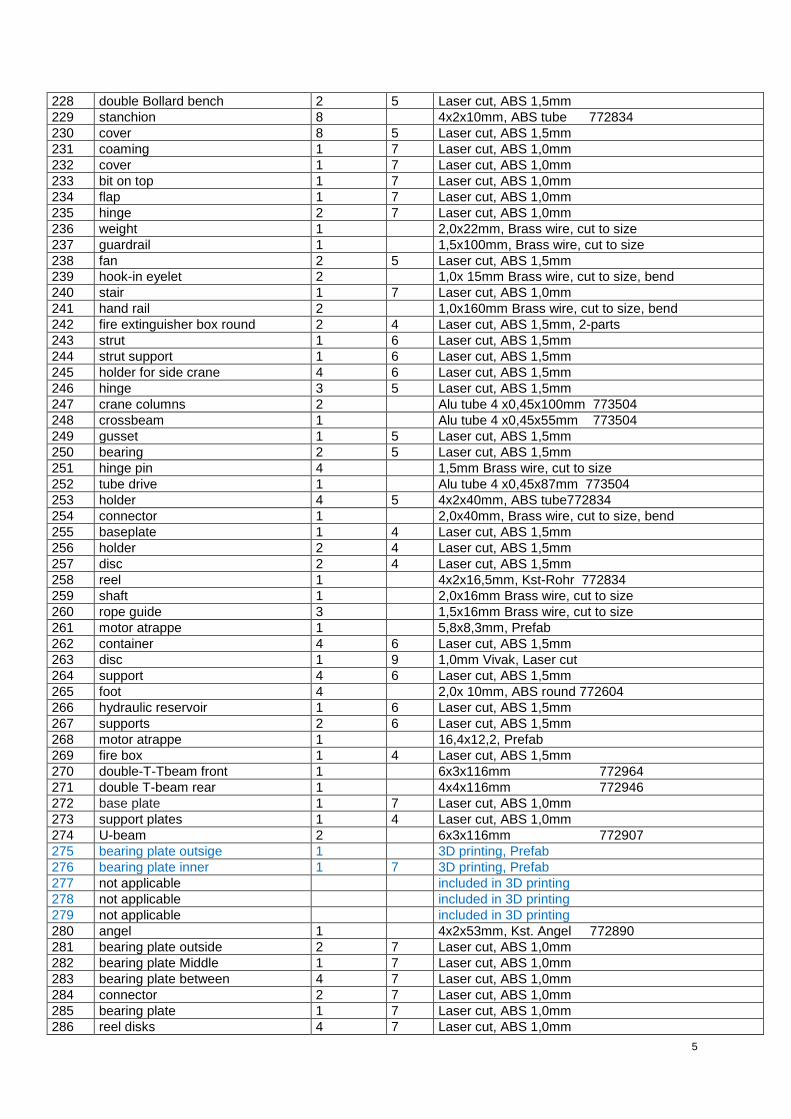
228 double Bollard bench 2 5 Laser cut, ABS 1,5mm
229 stanchion 8 4x2x10mm, ABS tube 772834
230 cover 8 5 Laser cut, ABS 1,5mm
231 coaming 1 7 Laser cut, ABS 1,0mm
232 cover 1 7 Laser cut, ABS 1,0mm
233 bit on top 1 7 Laser cut, ABS 1,0mm
234 flap 1 7 Laser cut, ABS 1,0mm
235 hinge 2 7 Laser cut, ABS 1,0mm
236 weight 1 2,0x22mm, Brass wire, cut to size
237 guardrail 1 1,5x100mm, Brass wire, cut to size
238 fan 2 5 Laser cut, ABS 1,5mm
239 hook-in eyelet 2 1,0x 15mm Brass wire, cut to size, bend
240 stair 1 7 Laser cut, ABS 1,0mm
241 hand rail 2 1,0x160mm Brass wire, cut to size, bend
242 fire extinguisher box round 2 4 Laser cut, ABS 1,5mm, 2-parts
243 strut 1 6 Laser cut, ABS 1,5mm
244 strut support 1 6 Laser cut, ABS 1,5mm
245 holder for side crane 4 6 Laser cut, ABS 1,5mm
246 hinge 3 5 Laser cut, ABS 1,5mm
247 crane columns 2 Alu tube 4 x0,45x100mm 773504
248 crossbeam 1 Alu tube 4 x0,45x55mm 773504
249 gusset 1 5 Laser cut, ABS 1,5mm
250 bearing 2 5 Laser cut, ABS 1,5mm
251 hinge pin 4 1,5mm Brass wire, cut to size
252 tube drive 1 Alu tube 4 x0,45x87mm 773504
253 holder 4 5 4x2x40mm, ABS tube772834
254 connector 1 2,0x40mm, Brass wire, cut to size, bend
255 baseplate 1 4 Laser cut, ABS 1,5mm
256 holder 2 4 Laser cut, ABS 1,5mm
257 disc 2 4 Laser cut, ABS 1,5mm
258 reel 1 4x2x16,5mm, Kst-Rohr 772834
259 shaft 1 2,0x16mm Brass wire, cut to size
260 rope guide 3 1,5x16mm Brass wire, cut to size
261 motor atrappe 1 5,8x8,3mm, Prefab
262 container 4 6 Laser cut, ABS 1,5mm
263 disc 1 9 1,0mm Vivak, Laser cut
264 support 4 6 Laser cut, ABS 1,5mm
265 foot 4 2,0x 10mm, ABS round 772604
266 hydraulic reservoir 1 6 Laser cut, ABS 1,5mm
267 supports 2 6 Laser cut, ABS 1,5mm
268 motor atrappe 1 16,4x12,2, Prefab
269 fire box 1 4 Laser cut, ABS 1,5mm
270 double-T-Tbeam front 1 6x3x116mm 772964
271 double T-beam rear 1 4x4x116mm 772946
272 base plate 1 7 Laser cut, ABS 1,0mm
273 support plates 1 4 Laser cut, ABS 1,0mm
274 U-beam 2 6x3x116mm 772907
275 bearing plate outsige 1 3D printing, Prefab
276 bearing plate inner 1 7 3D printing, Prefab
277 not applicable included in 3D printing
278 not applicable included in 3D printing
279 not applicable included in 3D printing
280 angel 1 4x2x53mm, Kst. Angel 772890
281 bearing plate outside 2 7 Laser cut, ABS 1,0mm
282 bearing plate Middle 1 7 Laser cut, ABS 1,0mm
283 bearing plate between 4 7 Laser cut, ABS 1,0mm
284 connector 2 7 Laser cut, ABS 1,0mm
285 bearing plate 1 7 Laser cut, ABS 1,0mm
286 reel disks 4 7 Laser cut, ABS 1,0mm
6
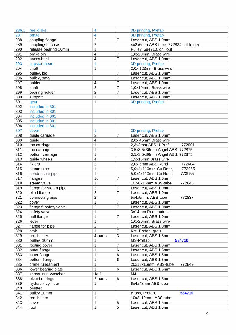
286.1 reel disks 4 3D printing, Prefab
287 brake 4 3D printing, Prefab
288 coupling flange 2 7 Laser cut, ABS 1,0mm
289 couplingsbuchse 2 4x2x6mm ABS-tube, 772834 cut to size,
290 release bearing 10mm 1 Pulley, 584710, drill out
291 brake pin 4 7 1,0x20mm, Brass wire
292 handwheel 4 7 Laser cut, ABS 1,0mm
293 capstan head 1 3D printing, Prefab
294 shaft 1 2,0x 123mm Brass wire
295 pulley, big 7 Laser cut, ABS 1,0mm
296 pulley, small 7 Laser cut, ABS 1,0mm
297 holder 4 7 Laser cut, ABS 1,0mm
298 shaft 2 7 1,0x10mm, Brass wire
299 bearing holder 2 7 Laser cut, ABS 1,0mm
300 support 1 7 Laser cut, ABS 1,0mm
301 gear 1 3D printing, Prefab
302 included in 301
303 included in 301
304 included in 301
305 included in 301
306 included in 301
307 cover 1 3D printing, Prefab
308 guide carriage 2 7 Laser cut, ABS 1,0mm
309 guide 4 2,0x 45mm Brass wire
310 top carriage 1 2,3x2mm ABS U-Profil, 772501
311 top carriage 1 3,5x3,5x36mm Angel ABS, 772875
312 bottom carriage 1 3,5x3,5x36mm Angel ABS, 772875
313 guide wheels 4 1,5x16mm Brass wire
314 fixiers 2 2,0x 5mm ABS-Rund 772604
315 steam pipe 1 5,0x4x110mm Cu-Rohr, 773955
316 condensate pipe 1 5,0x4x110mm Cu-Rohr, 773955
317 flanges 10 7 Laser cut, ABS 1,0mm
318 steam valve 1 10.x8x16mm ABS-tube 772846
319 flange for steam pipe 2 7 Laser cut, ABS 1,0mm
320 blind flange 2 7 Laser cut, ABS 1,0mm
321 connecting pipe 2 5x4x5mm, ABS-tube 772837
322 cover 1 7 Laser cut, ABS 1,0mm
323 flange f. safety valve 2 7 Laser cut, ABS 1,0mm
324 safety valve 1 3x14mm Rundmaterial
325 half flange 1 7 Laser cut, ABS 1,0mm
326 lever 1 1,0x20mm, Brass wire
327 flange for pipe 2 7 Laser cut, ABS 1,0mm
328 stair 1 7 Kst.-Prefab, grau
329 reel holder 4-parts 3 Laser cut, ABS 1,5mm
330 pulley 10mm 1 MS-Prefab, 584710
331 footing cover 1 7 Laser cut, ABS 1,0mm
332 outer flange 1 6 Laser cut, ABS 1,5mm
333 inner flange 1 6 Laser cut, ABS 1,5mm
334 botton flange 1 6 Laser cut, ABS 1,5mm
335 crane fundament 1 20x18x16mm, ABS-tube 772849
336 lower bearing plate 1 6 Laser cut, ABS 1,5mm
337 screw+nut+wascher Je 1 M4
338 pivot bearings 2-parts 6 Laser cut, ABS 1,5mm
339 hydrauik cylinder 1 6x4x48mm ABS tube
340 omitted
341 pulley 10mm 1 Brass, Prefab, 584710
342 reel holder 1 10x8x12mm, ABS tube
343 cover 1 5 Laser cut, ABS 1,5mm
344 foot 1 5 Laser cut, ABS 1,5mm
7
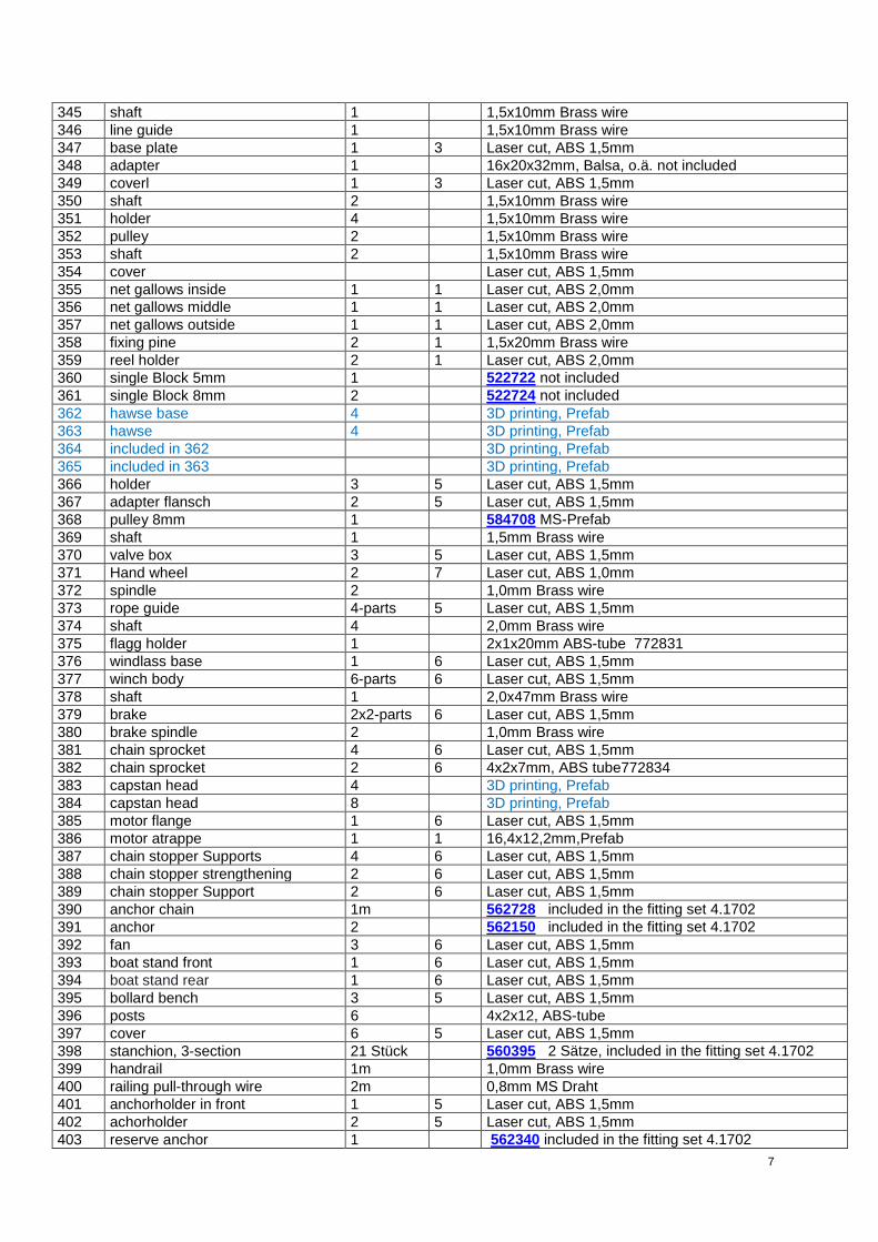
345 shaft 1 1,5x10mm Brass wire
346 line guide 1 1,5x10mm Brass wire
347 base plate 1 3 Laser cut, ABS 1,5mm
348 adapter 1 16x20x32mm, Balsa, o.ä. not included
349 coverl 1 3 Laser cut, ABS 1,5mm
350 shaft 2 1,5x10mm Brass wire
351 holder 4 1,5x10mm Brass wire
352 pulley 2 1,5x10mm Brass wire
353 shaft 2 1,5x10mm Brass wire
354 cover Laser cut, ABS 1,5mm
355 net gallows inside 1 1 Laser cut, ABS 2,0mm
356 net gallows middle 1 1 Laser cut, ABS 2,0mm
357 net gallows outside 1 1 Laser cut, ABS 2,0mm
358 fixing pine 2 1 1,5x20mm Brass wire
359 reel holder 2 1 Laser cut, ABS 2,0mm
360 single Block 5mm 1 522722 not included
361 single Block 8mm 2 522724 not included
362 hawse base 4 3D printing, Prefab
363 hawse 4 3D printing, Prefab
364 included in 362 3D printing, Prefab
365 included in 363 3D printing, Prefab
366 holder 3 5 Laser cut, ABS 1,5mm
367 adapter flansch 2 5 Laser cut, ABS 1,5mm
368 pulley 8mm 1 584708 MS-Prefab
369 shaft 1 1,5mm Brass wire
370 valve box 3 5 Laser cut, ABS 1,5mm
371 Hand wheel 2 7 Laser cut, ABS 1,0mm
372 spindle 2 1,0mm Brass wire
373 rope guide 4-parts 5 Laser cut, ABS 1,5mm
374 shaft 4 2,0mm Brass wire
375 flagg holder 1 2x1x20mm ABS-tube 772831
376 windlass base 1 6 Laser cut, ABS 1,5mm
377 winch body 6-parts 6 Laser cut, ABS 1,5mm
378 shaft 1 2,0x47mm Brass wire
379 brake 2x2-parts 6 Laser cut, ABS 1,5mm
380 brake spindle 2 1,0mm Brass wire
381 chain sprocket 4 6 Laser cut, ABS 1,5mm
382 chain sprocket 2 6 4x2x7mm, ABS tube772834
383 capstan head 4 3D printing, Prefab
384 capstan head 8 3D printing, Prefab
385 motor flange 1 6 Laser cut, ABS 1,5mm
386 motor atrappe 1 1 16,4x12,2mm,Prefab
387 chain stopper Supports 4 6 Laser cut, ABS 1,5mm
388 chain stopper strengthening 2 6 Laser cut, ABS 1,5mm
389 chain stopper Support 2 6 Laser cut, ABS 1,5mm
390 anchor chain 1m 562728 included in the fitting set 4.1702
391 anchor 2 562150 included in the fitting set 4.1702
392 fan 3 6 Laser cut, ABS 1,5mm
393 boat stand front 1 6 Laser cut, ABS 1,5mm
394 boat stand rear 1 6 Laser cut, ABS 1,5mm
395 bollard bench 3 5 Laser cut, ABS 1,5mm
396 posts 6 4x2x12, ABS-tube
397 cover 6 5 Laser cut, ABS 1,5mm
398 stanchion, 3-section 21 Stück 560395 2 Sätze, included in the fitting set 4.1702
399 handrail 1m 1,0mm Brass wire
400 railing pull-through wire 2m 0,8mm MS Draht
401 anchorholder in front 1 5 Laser cut, ABS 1,5mm
402 achorholder 2 5 Laser cut, ABS 1,5mm
403 reserve anchor 1 562340 included in the fitting set 4.1702
8
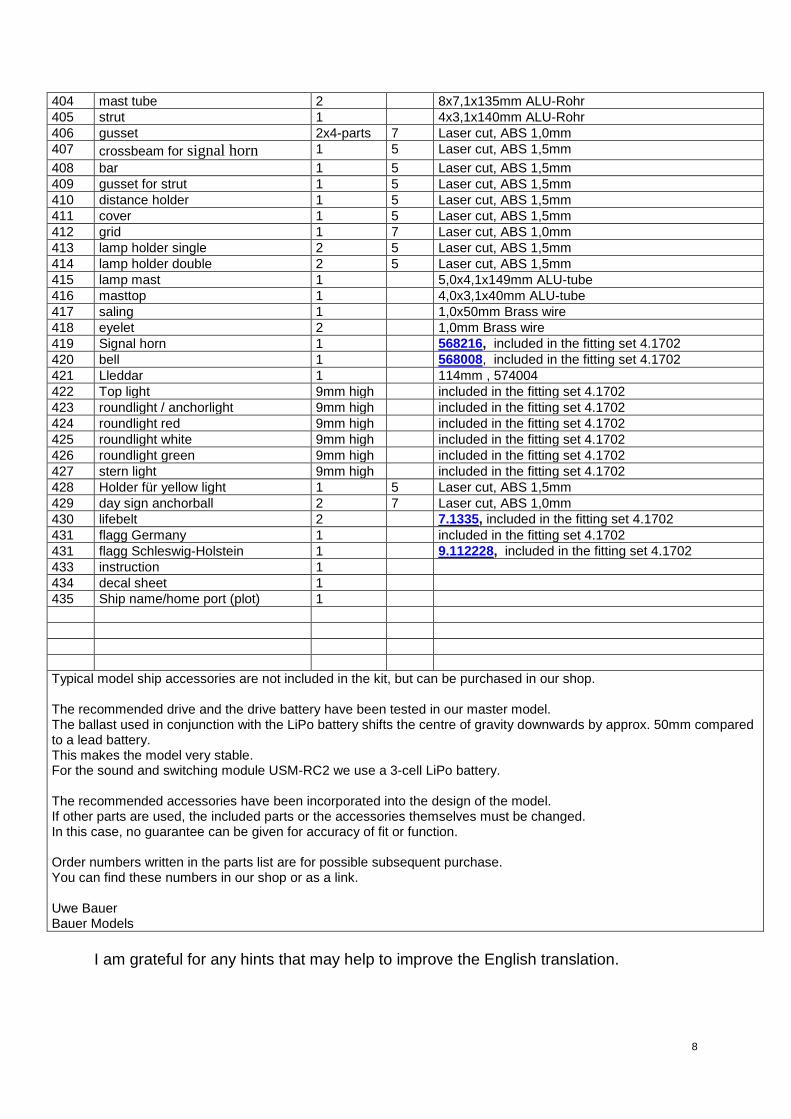
404 mast tube 2 8x7,1x135mm ALU-Rohr
405 strut 1 4x3,1x140mm ALU-Rohr
406 gusset 2x4-parts 7 Laser cut, ABS 1,0mm
407 crossbeam for signal horn 1 5 Laser cut, ABS 1,5mm
408 bar 1 5 Laser cut, ABS 1,5mm
409 gusset for strut 1 5 Laser cut, ABS 1,5mm
410 distance holder 1 5 Laser cut, ABS 1,5mm
411 cover 1 5 Laser cut, ABS 1,5mm
412 grid 1 7 Laser cut, ABS 1,0mm
413 lamp holder single 2 5 Laser cut, ABS 1,5mm
414 lamp holder double 2 5 Laser cut, ABS 1,5mm
415 lamp mast 1 5,0x4,1x149mm ALU-tube
416 masttop 1 4,0x3,1x40mm ALU-tube
417 saling 1 1,0x50mm Brass wire
418 eyelet 2 1,0mm Brass wire
419 Signal horn 1 568216, included in the fitting set 4.1702
420 bell 1 568008, included in the fitting set 4.1702
421 Lleddar 1 114mm , 574004
422 Top light 9mm high included in the fitting set 4.1702
423 roundlight / anchorlight 9mm high included in the fitting set 4.1702
424 roundlight red 9mm high included in the fitting set 4.1702
425 roundlight white 9mm high included in the fitting set 4.1702
426 roundlight green 9mm high included in the fitting set 4.1702
427 stern light 9mm high included in the fitting set 4.1702
428 Holder für yellow light 1 5 Laser cut, ABS 1,5mm
429 day sign anchorball 2 7 Laser cut, ABS 1,0mm
430 lifebelt 2 7.1335, included in the fitting set 4.1702
431 flagg Germany 1 included in the fitting set 4.1702
431 flagg Schleswig-Holstein 1 9.112228, included in the fitting set 4.1702
433 instruction 1
434 decal sheet 1
435 Ship name/home port (plot) 1
Typical model ship accessories are not included in the kit, but can be purchased in our shop. The recommended drive and the drive battery have been tested in our master model. The ballast used in conjunction with the LiPo battery shifts the centre of gravity downwards by approx. 50mm compared to a lead battery. This makes the model very stable. For the sound and switching module USM-RC2 we use a 3-cell LiPo battery. The recommended accessories have been incorporated into the design of the model. If other parts are used, the included parts or the accessories themselves must be changed. In this case, no guarantee can be given for accuracy of fit or function. Order numbers written in the parts list are for possible subsequent purchase. You can find these numbers in our shop or as a link. Uwe Bauer Bauer Models
I am grateful for any hints that may help to improve the English translation.
1111
29
24
22
141414
13
Blindflansche für Abgasrohr unter das Hauptdeck kleben
355
356
357
22
223 225
359
317
286
317
37131
7299
308308
281 281
282
317
282282
182 182181
135 141
292292292292
131.129913113128
3
273 273
284 325323
3203
27
319
297
296 295
295296
296 295
295296288
284
275
406406
108
282
92.1
306
305
272
103.1103 101
429
105
105.1
100
99
98
60
240
429
60
235
183
137
134
317
317
317
317
317
317
317
317
317
317
198
136
138
106 106
102
104
107109107
35
35
232 233 234
3636
3636
36
286
131.1
286
286300
331
95 95
98.1
96
94
93
92
240
231
184
91
97
90
87
87
88
84
87
89
87
8484
263 84
84
84
84
84
111
84
111
89
88
87
87
87
87
87
87
87
89
88 88 88 88 88