Luftheizgeräte Einbauanweisung Air Heaters Installation ... · Installation Instructions ... Das...
44
Luftheizgeräte Air Heaters Luchtverwarmingsapparaten Einbauanweisung Installation Instructions Montagehandleiding Air Top 2000 ST Handelsbezeichnungen/Trade names/Handelsnamen: Air Top 2000 ST B (Benzin/Petrol/benzine) Air Top 2000 ST D (Diesel/PME)
Transcript of Luftheizgeräte Einbauanweisung Air Heaters Installation ... · Installation Instructions ... Das...

LuftheizgeräteAir HeatersLuchtverwarmingsapparaten
EinbauanweisungInstallation InstructionsMontagehandleiding
Air Top 2000 STHandelsbezeichnungen/Trade names/Handelsnamen:
Air Top 2000 ST B (Benzin/Petrol/benzine)Air Top 2000 ST D (Diesel/PME)
AT2000ST_Installation_Instructions.book Page 1 Wednesday, May 29, 2013 12:54 PM
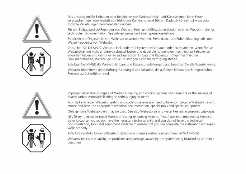
Das unsachgemäße Einbauen oder Reparieren von Webasto Heiz- und Kühlsystemen kann Feuerverursachen oder zum Austritt von tödlichem Kohlenmonoxid führen. Dadurch können schwere odertödliche Verletzungen hervorgerufen werden.
Für den Einbau und die Reparatur von Webasto Heiz- und Kühlsystemen bedarf es eines Webastotrainings,technischer Dokumentation, Spezialwerkzeuge und einer Spezialausrüstung.
Es dürfen nur Originalteile von Webasto verwendet werden. Siehe dazu auch Zubehörkatalog Luft- undWasserheizgeräte von Webasto.
Versuchen Sie NIEMALS, Webasto Heiz- oder Kühlsysteme einzubauen oder zu reparieren, wenn Sie dasWebastotraining nicht erfolgreich abgeschlossen und dabei die notwendigen technischen Fähigkeitenerworben haben und die für einen sachgerechten Einbau und Reparatur nötigen technischenDokumentationen, Werkzeuge und Ausrüstungen nicht zur Verfügung stehen.
Befolgen Sie IMMER alle Webasto Einbau- und Reparaturanleitungen, und beachten Sie alle Warnhinweise.
Webasto übernimmt keine Haftung für Mängel und Schäden, die auf einen Einbau durch ungeschultesPersonal zurückzuführen sind.
Improper installation or repair of Webasto heating and cooling systems can cause fire or the leakage ofdeadly carbon monoxide leading to serious injury or death.
To install and repair Webasto heating and cooling systems you need to have completed a Webasto trainingcourse and have the appropriate technical documentation, special tools and special equipment.
Only genuine Webasto parts may be used. See also Webasto air and water heaters accessories catalogue.
NEVER try to install or repair Webasto heating or cooling systems if you have not completed a Webastotraining course, you do not have the necessary technical skills and you do not have the technicaldocumentation, tools and equipment available to ensure that you can complete the installation and repairwork properly.
ALWAYS carefully follow Webasto installation and repair instructions and heed all WARNINGS.
Webasto rejects any liability for problems and damage caused by the system being installed by untrainedpersonnel.
AT2000ST_Installation_Instructions.book Page 1 Wednesday, May 29, 2013 12:54 PM

Air Top 2000 ST
I
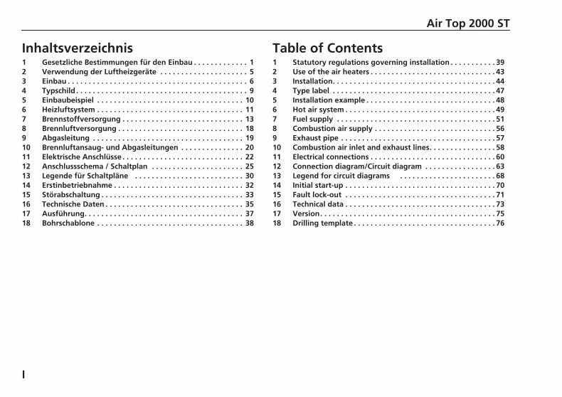
Inhaltsverzeichnis1 Gesetzliche Bestimmungen für den Einbau . . . . . . . . . . . . . 12 Verwendung der Luftheizgeräte . . . . . . . . . . . . . . . . . . . . . 53 Einbau . . . . . . . . . . . . . . . . . . . . . . . . . . . . . . . . . . . . . . . . . . . 64 Typschild . . . . . . . . . . . . . . . . . . . . . . . . . . . . . . . . . . . . . . . . . 95 Einbaubeispiel . . . . . . . . . . . . . . . . . . . . . . . . . . . . . . . . . . . 106 Heizluftsystem . . . . . . . . . . . . . . . . . . . . . . . . . . . . . . . . . . . 117 Brennstoffversorgung . . . . . . . . . . . . . . . . . . . . . . . . . . . . . 138 Brennluftversorgung . . . . . . . . . . . . . . . . . . . . . . . . . . . . . . 189 Abgasleitung . . . . . . . . . . . . . . . . . . . . . . . . . . . . . . . . . . . . 1910 Brennluftansaug- und Abgasleitungen . . . . . . . . . . . . . . . 2011 Elektrische Anschlüsse . . . . . . . . . . . . . . . . . . . . . . . . . . . . . 2212 Anschlussschema / Schaltplan . . . . . . . . . . . . . . . . . . . . . . 2513 Legende für Schaltpläne . . . . . . . . . . . . . . . . . . . . . . . . . . 3014 Erstinbetriebnahme . . . . . . . . . . . . . . . . . . . . . . . . . . . . . . . 3215 Störabschaltung . . . . . . . . . . . . . . . . . . . . . . . . . . . . . . . . . . 3316 Technische Daten . . . . . . . . . . . . . . . . . . . . . . . . . . . . . . . . . 3517 Ausführung. . . . . . . . . . . . . . . . . . . . . . . . . . . . . . . . . . . . . . 3718 Bohrschablone . . . . . . . . . . . . . . . . . . . . . . . . . . . . . . . . . . . 38
Table of Contents1 Statutory regulations governing installation . . . . . . . . . . . 392 Use of the air heaters . . . . . . . . . . . . . . . . . . . . . . . . . . . . . . 433 Installation. . . . . . . . . . . . . . . . . . . . . . . . . . . . . . . . . . . . . . . 444 Type label . . . . . . . . . . . . . . . . . . . . . . . . . . . . . . . . . . . . . . . 475 Installation example . . . . . . . . . . . . . . . . . . . . . . . . . . . . . . . 486 Hot air system . . . . . . . . . . . . . . . . . . . . . . . . . . . . . . . . . . . . 497 Fuel supply . . . . . . . . . . . . . . . . . . . . . . . . . . . . . . . . . . . . . . 518 Combustion air supply . . . . . . . . . . . . . . . . . . . . . . . . . . . . . 569 Exhaust pipe . . . . . . . . . . . . . . . . . . . . . . . . . . . . . . . . . . . . . 5710 Combustion air inlet and exhaust lines. . . . . . . . . . . . . . . . 5811 Electrical connections . . . . . . . . . . . . . . . . . . . . . . . . . . . . . . 6012 Connection diagram/Circuit diagram . . . . . . . . . . . . . . . . . 6313 Legend for circuit diagrams . . . . . . . . . . . . . . . . . . . . . . . 6814 Initial start-up . . . . . . . . . . . . . . . . . . . . . . . . . . . . . . . . . . . . 7015 Fault lock-out . . . . . . . . . . . . . . . . . . . . . . . . . . . . . . . . . . . . 7116 Technical data . . . . . . . . . . . . . . . . . . . . . . . . . . . . . . . . . . . . 7317 Version. . . . . . . . . . . . . . . . . . . . . . . . . . . . . . . . . . . . . . . . . . 7518 Drilling template . . . . . . . . . . . . . . . . . . . . . . . . . . . . . . . . . . 76
AT2000ST_Installation_Instructions.book Page I Wednesday, May 29, 2013 12:54 PM
Air Top 2000 ST Statutory regulations governing installation
39
1 Statutory regulations governing installation
Type approvals according to ECE-R 10 (EMC) and ECE-R 122 (Heater) existfor the Air Top 2000 ST heater.
See chapter 16, "Technical data" for the approval number.
Primarily the regulations of Part I and Annex 7 of the directive ECE-R 122must be observed for the installation.
NOTE:The specifications of this Directive are binding in the scope of theBasic Directive EEC/70/156 and/or EC/2007/46 (for new vehiclemodels from 29/04/2009) and should also be observed in countriesin which no special regulations exist.
See chapter 1.2, "Extract of the directives 2001/56/EG Annex VII andECE R122 Part I and Annex 7" and chapter 1.3, "Extract of the direc-tives 2001/56/EG Annex IX and ECE R122 Annex 9".
IMPORTANTFailure to follow the installation instructions and the notes containedtherein will lead to all liability being refused by Webasto. The same appliesif repairs are carried out incorrectly or with the use of parts other than gen-uine spare parts. This will result in the invalidation of the type approval forthe heater and therefore of its homologation/ECE type licence.
1.1. Application of combustion heaters in vehicles for transport-ing dangerous goods
Vehicles for the purpose of transporting dangerous goods will be type test-ed in accordance with the standard ECE R105. The following measures arederived for our combustion heaters:
• The electrical cable/wiring harness must be sufficiently dimensioned toprevent overheating. The electrical cable/wiring harness must be suffi-ciently insulated. All power circuits must be protected with fuses or au-tomatic circuit-breakers.
• The cables must be securely fastened and routed so that they are suffi-ciently protected against mechanical and thermal loading.
• The combustion heaters must be type-tested in accordance with thestandard ECE R122 (equivalent to EC/2001/56 in the version EC/2006/119) and comply with the Appendix 9 – Additional regulations for ve-hicles for transporting dangerous goods.
• The combustion heaters and their exhaust gas routing shall be de-signed, located, protected or covered so as to prevent any unacceptablerisk of heating or ignition of the load.
• In the event of any leakage of the fuel line, the fuel shall drain to theground without coming into contact with hot parts of the vehicle or theload;
• The exhaust system as well as the exhaust pipes shall be so directed orprotected to avoid any danger to the load through heating or ignition.Parts of the exhaust system situated directly below the fuel tank shallhave a clearance of at least 100 mm or be protected by a thermal shield.
• The combustion heater may only be switched on manually. Program-ming devices shall be prohibited. The combustion heater may beswitched on again manually after the vehicle engine has been switchedoff.
AT2000ST_Installation_Instructions.book Page 39 Wednesday, May 29, 2013 12:54 PM

Statutory regulations governing installation Air Top 2000 ST
40
Requirement for basic unit:
A maximum run-on period of 40 seconds is permitted when the combus-tion heater is switched off. Only combustion heaters with heat exchangersthat are approved for this reduced run-on time of 40 seconds may be used.
1.2. Extract from directive ECE-R 122 Part I and Annex 7Start of extract.
Part I
5.3 Vehicle Installation Requirements for Combustion Heaters andfor Electric Heaters
5.3.1 Scope
5.3.1.1 Subject to paragraph 5.3.1.2, heaters shall be installed accordingto the requirements of paragraph 5.3.
5.3.1.2 Vehicles of category O having liquid fuel heaters are deemed tocomply with the requirements of paragraph 5.3.
5.3.2 Positioning of heater
5.3.2.1 Body sections and any other components in the vicinity of the heat-er must be protected from excessive heat and the possibility of fuel or oilcontamination.
5.3.2.2 The heater shall not constitute a risk of fire, even in the case ofoverheating. This requirement shall be deemed to be met if the installationensures an adequate distance to all parts and suitable ventilation, by theuse of fire resistant materials or by the use of heat shields.
5.3.2.3 In the case of M2 and M3 vehicles, the combustion heater mustnot be positioned in the passenger compartment. However, an installationin an effectively sealed envelope which also complies with the conditionsin paragraph 5.3.2.2 may be used.
5.3.2.4 The label referred to in Annex 7, paragraph 4, or a duplicate, mustbe positioned so that it can be easily read when the combustion heater isinstalled in the vehicle.
5.3.2.5 Every reasonable precaution should be taken in positioning theheater to minimize the risk of injury and damage to personal property.
5.3.3 Fuel supply
5.3.3.1 The fuel filler must not be situated in the passenger compartmentand must be provided with an effective cap to prevent fuel spillage.
5.3.3.2 In the case of liquid fuel heaters, where a supply separate from thatof the vehicle is provided, the type of fuel and its filler point must be clearlylabelled.
5.3.3.3 A notice, indicating that the heater must be shut down before re-fuelling, must be affixed to the fuelling point. In addition a suitable instruc-tion must be included in the manufacturer’s operating manual.
5.3.4 Exhaust system
5.3.4.1 The exhaust outlet must be located so as to prevent emissions fromentering the vehicle through ventilators, heated air inlets or opening win-dows.
5.3.5 Combustion air inlet
5.3.5.1 The air for the combustion chamber of the heater must not bedrawn from the passenger compartment of the vehicle.
5.3.5.2 The air inlet must be so positioned or guarded that blocking by rub-bish or luggage is unlikely.
5.3.6 Heating air inlet
5.3.6.1 The heating air supply may be fresh or re-circulated air and mustbe drawn from a clean area not likely to be contaminated by exhaustfumes emitted either by the propulsion engine, the combustion heater orany other vehicle source.
AT2000ST_Installation_Instructions.book Page 40 Wednesday, May 29, 2013 12:54 PM
Air Top 2000 ST Statutory regulations governing installation
41
5.3.6.2 The inlet duct must be protected by mesh or other suitable means.
5.3.7 Heating air outlet
5.3.7.1 Any ducting used to route the hot air through the vehicle must beso positioned or protected that no injury or damage could be caused if itwere to be touched.
5.3.7.2 The air outlet must be so positioned or guarded that blocking byrubbish or luggage is unlikely.
5.3.8 Automatic control of the heating system
5.3.8.1 The heating system must be switched off automatically and thesupply of fuel must be stopped within five seconds when the vehicle’s en-gine stops running. If a manual device is already activated, the heating sys-tem can stay in operation.
ANNEX 7
ADDITIONAL REQUIREMENTS FOR COMBUSTION HEATERS
7 Warning light
7.1 A clearly visible tell-tale in the operator’s field of view shall informwhen the combustion heater is switched on or off.
End of extract.
NOTE:Contrary to point 5.3.2.3 the heater must also not be installed in thepassenger cabin of class M1 and N vehicles. However, an installation in aneffectively sealed envelope which also complies with the conditions inparagraph 5.3.2.2 may be used.
1.3. Extract from directive ECE-R 122 Annex 9Start of extract.
Additional provisions applicable to certain vehicles as specified in the ADR.
3. Technical Provisions
3.1 General (EX/II, EX/III, AT, FL, OX and MEMU vehicles)
3.1.1 [1] The combustion heaters and their exhaust gas routing shall be de-signed, located, protected or covered so as to prevent any unacceptablerisk of heating or ignition of the load. This requirement shall be consideredas fulfilled if the fuel tank and the exhaust system of the appliance conformto the following provisions:
- Any fuel tanks for supplying the appliance shall meet the followingrequirements:
a) In the event of any leakage, the fuel shall drain to the groundwithout coming into contact with hot parts of the vehicle orthe load;
b) Fuel tanks containing petrol shall be equipped with an effec-tive flame trap at the filler opening or with a closure enablingthe opening to be kept hermetically sealed.
- The exhaust system as well as the exhaust pipes shall be so directedor protected to avoid any danger to the load through heating or ig-nition. Parts of the exhaust system situated directly below the fueltank (diesel) shall have a clearance of at least 100 mm or be protect-ed by a thermal shield.
3.1.2 The combustion heater shall be switched on manually. Programmingdevices shall be prohibited.
3.2 EX/II, EX/III and MEMU vehicles
Combustion heaters using gaseous fuels are not permitted.
AT2000ST_Installation_Instructions.book Page 41 Wednesday, May 29, 2013 12:54 PM
Statutory regulations governing installation Air Top 2000 ST
42
3.3 FL vehicles
3.3.1 The combustion heaters shall be put out of operation by at least thefollowing methods:
a) Intentional manual switching off from the driver’s cab;
b) Stopping of the vehicle engine; in this case the heating devicemay be restarted manually by the driver;
c) Start up of a feed pump on the motor vehicle for the danger-ous goods carried.
[1] Compliance with this paragraph shall be verified on the completed ve-hicle.
End of extract.
AT2000ST_Installation_Instructions.book Page 42 Wednesday, May 29, 2013 12:54 PM
Air Top 2000 ST Use of the air heaters
43
2 Use of the air heaters
The Webasto Air Top 2000 ST air heaters are designed– to heat cabins, boats, trucks, minibuses, vans and motorhomes– to defrost vehicle windows
The heaters operate independently of the engine and are connected direct-ly to the fuel tank and the electrical system of the vehicle.
They may be used for vehicles with either water or air-cooled engines.
They are not designed for heating hazardous substances.
AT2000ST_Installation_Instructions.book Page 43 Wednesday, May 29, 2013 12:54 PM
Installation Air Top 2000 ST
44
3 Installation
IMPORTANTThe statutory regulations governing installation on pages 1 and 2 must beadhered to. The requirements of the latest version of the ADR must also beobserved for the installing the heater into vehicles used to transport haz-ardous substances.The heater must not be operated without the control unit cover (this willcause the heater to overheat).
3.1. Air Top 2000 ST installation situation
NOTE:Check the installation situation of the relevant vehicle type.
3.2. Installation locationThe heater may be fitted both in the interior or on the exterior of the vehi-cle.When using the vehicle in normal road traffic, the heater may only be in-stalled with contact protection if it is located within reach of the driver.If it is installed on the exterior ensure that the heater is fitted in a positionwhere it is protected from splashing water and spray.
The heater must be installed in such a way that no water can ingress intoit if the vehicle travels through a water hazard for which that vehicle is li-censed.
The openings for the combustion air inlet port, the exhaust outlet port andthe fuel pipe must be sealed if the heater is installed in the interior. The sealdesigned and supplied for this purpose must be used (see Figure 3).
3.3. To install the heaterThe M6 nuts must be tightened with a torque of 6 Nm +1 Nm for installingthe Air Top 2000 ST heater.
The installation dimensions and space requirement for service access areshown in the installation drawing (Figure 1). The specified horizontal andaxial angles must not be exceeded (Figure 2).
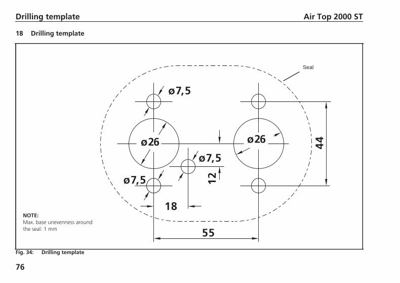
A seal (Figure 3) must be fitted between the heater and the vehicle body.This seal must be replaced each time the heater is installed. The sup-port area for the heater foot must be flat. A special tools can be pur-chased from Webasto to drill the holes and, if necessary, smooth the sup-port area. The seal can compensate for unevenness of max. 1 mm.
IMPORTANTAfter installation, check that the casing is not in contact with any parts ofthe vehicle body. A failure to do this may result in the hot air fan blocking.
AT2000ST_Installation_Instructions.book Page 44 Wednesday, May 29, 2013 12:54 PM

Fig. 1: Dimensions of the heater
1 Hot air inlet2 Hot air outlet3 Combustion air intake4 Exhaust fume outlet
5 Fuel intake6 Space requirement for hot air inlet7 Space requirement for removing the heater8 Cable outlet (either right or left)
1 2
3 5 4
7
8
6
Air Top 2000 ST Installation
45
AT2000ST_Installation_Instructions.book Page 45 Wednesday, May 29, 2013 12:54 PM
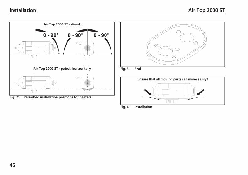
Fig. 2: Permitted installation positions for heaters
Air Top 2000 ST - diesel:
Air Top 2000 ST - petrol: horizontally Fig. 3: Seal
Fig. 4: Installation
Ensure that all moving parts can move easily!
Installation Air Top 2000 ST
46
AT2000ST_Installation_Instructions.book Page 46 Wednesday, May 29, 2013 12:54 PM
Air Top 2000 ST Type label
47
4 Type label
The model plate must be positioned so that it cannot be damaged andmust be clearly legible when the heater is installed (otherwise a duplicatemodel plate must be used).
Inapplicable years must be erased from the model plate.
AT2000ST_Installation_Instructions.book Page 47 Wednesday, May 29, 2013 12:54 PM
Installation example Air Top 2000 ST
48
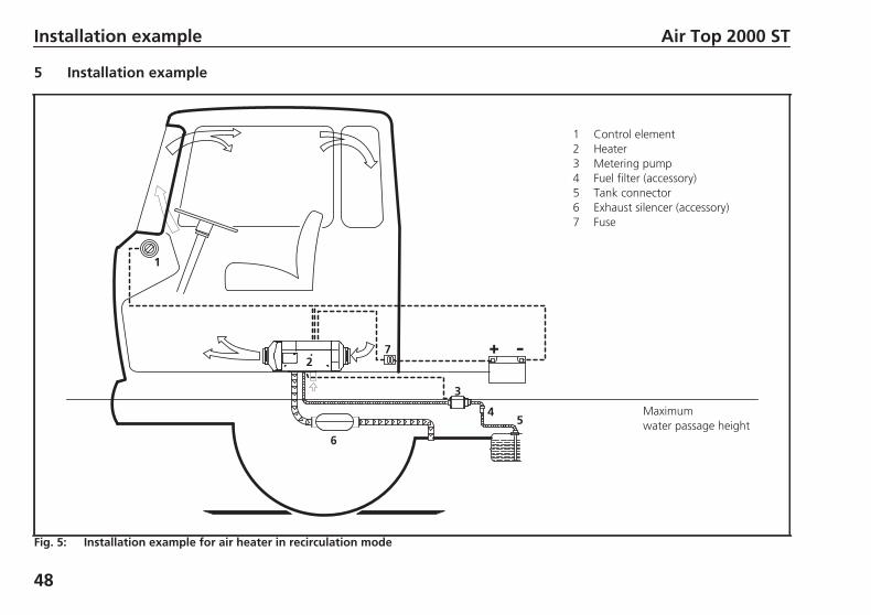
5 Installation example
Fig. 5: Installation example for air heater in recirculation mode
1 Control element2 Heater3 Metering pump4 Fuel filter (accessory)5 Tank connector6 Exhaust silencer (accessory)7 Fuse
Maximumwater passage height
1
2
3
54
7
6
AT2000ST_Installation_Instructions.book Page 48 Wednesday, May 29, 2013 12:54 PM

Air Top 2000 ST Hot air system
49
6 Hot air system
NOTE:The heater must not be integrated into the vehicle’s air system.
Inside the control unit there is a temperature sensor, which operates theheater in the appropriate heat output range in conjunction with the controlelement depending on the intake temperatures and the position of the set-point generator. The heat output is controlled such that after the selectedinterior temperature has been reached quickly, it is then kept at this select-ed value.
Both recirculation and fresh air modes are possible.
For fresh air mode it must be ensured that the hot air is taken from an areaprotected from splashing water and spray and in such a way that no watercan ingress into the heater if the vehicle travels through a water hazard forwhich that vehicle is licensed.
NOTE:For fresh air mode an external temperature sensor must be fitted in the ap-propriate zone.
The internal diameter of the main section of the hot air line should be 60mm.
NOTE:Only materials that can permanently withstand temperatures of at least130 °C may be used for the hot air line. The hot air opening is to be posi-tioned in such a way that the air is not blown on to any parts that cannotwithstand the heat.
IMPORTANTIn vehicles used to transport people, the air outlet opening is to be directedin such a way that it is at least 20 cm away from all body parts.
Maximum pressure drop between the inlet and outlet side of the hot airline:Air Top 2000 ST 1.5 hPa1 hPa corresponds to 1 mbar corresponds to 10mm WC (water column).
The heaters check the internal temperature rise automatically each timethey are switched on. If this is above the specified limits, the start is can-celled and error messages F10 is displayed. To ensure that the heater func-tions stably, the flow resistance of the connected hot air system must bereduced.
The points table for air guide parts in the Webasto catalogue may be usedto design the hot air system.
The hot air hose must be secured at its connection points.
If the heater is used in recirculation mode without a hot air guide, do notshort circuit the hot air flow.
Fig. 6: Hot air inlet and hot air outlet
AT2000ST_Installation_Instructions.book Page 49 Wednesday, May 29, 2013 12:54 PM
Hot air system Air Top 2000 ST
50
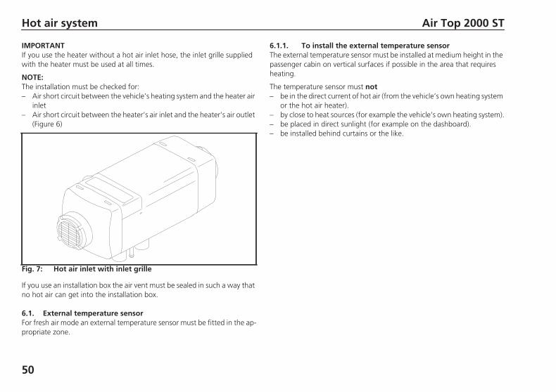
IMPORTANTIf you use the heater without a hot air inlet hose, the inlet grille suppliedwith the heater must be used at all times.
NOTE:The installation must be checked for:– Air short circuit between the vehicle’s heating system and the heater air
inlet– Air short circuit between the heater’s air inlet and the heater’s air outlet
(Figure 6)
Fig. 7: Hot air inlet with inlet grille
If you use an installation box the air vent must be sealed in such a way thatno hot air can get into the installation box.
6.1. External temperature sensorFor fresh air mode an external temperature sensor must be fitted in the ap-propriate zone.
6.1.1. To install the external temperature sensorThe external temperature sensor must be installed at medium height in thepassenger cabin on vertical surfaces if possible in the area that requiresheating.
The temperature sensor must not– be in the direct current of hot air (from the vehicle’s own heating system
or the hot air heater).– by close to heat sources (for example the vehicle’s own heating system).– be placed in direct sunlight (for example on the dashboard).– be installed behind curtains or the like.
AT2000ST_Installation_Instructions.book Page 50 Wednesday, May 29, 2013 12:54 PM
Air Top 2000 ST Fuel supply
51
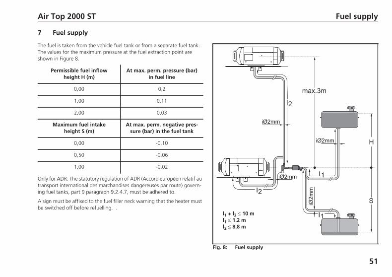
7 Fuel supply
The fuel is taken from the vehicle fuel tank or from a separate fuel tank.The values for the maximum pressure at the fuel extraction point areshown in Figure 8.
Permissible fuel inflowheight H (m)
At max. perm. pressure (bar)in fuel line
0,00 0,2
1,00 0,11
2,00 0,03
Maximum fuel intakeheight S (m)
At max. perm. negative pres-sure (bar) in the fuel tank
0,00 -0,10
0,50 -0,06
1,00 -0,02
Only for ADR: The statutory regulation of ADR (Accord européen relatif autransport international des marchandises dangereuses par route) govern-ing fuel tanks, part 9 paragraph 9.2.4.7, must be adhered to.
A sign must be affixed to the fuel filler neck warning that the heater mustbe switched off before refuelling.
Fig. 8: Fuel supply
l1 + l2 10 ml1 1.2 ml2 8.8 m
.
AT2000ST_Installation_Instructions.book Page 51 Wednesday, May 29, 2013 12:54 PM
Fuel supply Air Top 2000 ST
52
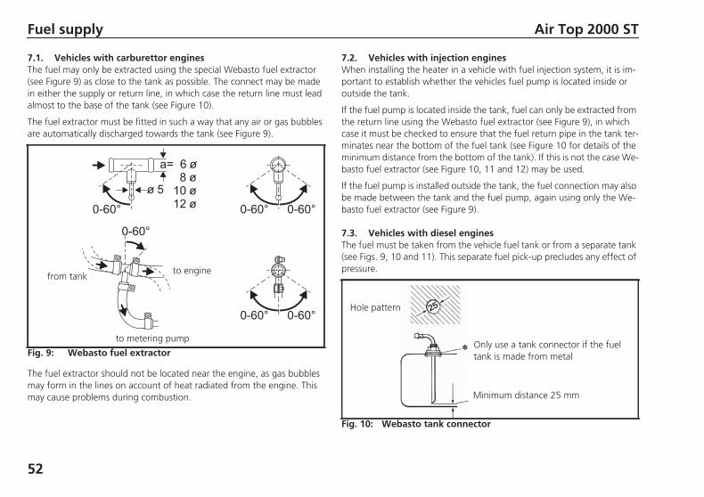
7.1. Vehicles with carburettor enginesThe fuel may only be extracted using the special Webasto fuel extractor(see Figure 9) as close to the tank as possible. The connect may be madein either the supply or return line, in which case the return line must leadalmost to the base of the tank (see Figure 10).
The fuel extractor must be fitted in such a way that any air or gas bubblesare automatically discharged towards the tank (see Figure 9).
Fig. 9: Webasto fuel extractor
to metering pump
to enginefrom tank
The fuel extractor should not be located near the engine, as gas bubblesmay form in the lines on account of heat radiated from the engine. Thismay cause problems during combustion.
7.2. Vehicles with injection enginesWhen installing the heater in a vehicle with fuel injection system, it is im-portant to establish whether the vehicles fuel pump is located inside oroutside the tank.
If the fuel pump is located inside the tank, fuel can only be extracted fromthe return line using the Webasto fuel extractor (see Figure 9), in whichcase it must be checked to ensure that the fuel return pipe in the tank ter-minates near the bottom of the fuel tank (see Figure 10 for details of theminimum distance from the bottom of the tank). If this is not the case We-basto fuel extractor (see Figure 10, 11 and 12) may be used.
If the fuel pump is installed outside the tank, the fuel connection may alsobe made between the tank and the fuel pump, again using only the We-basto fuel extractor (see Figure 9).
7.3. Vehicles with diesel enginesThe fuel must be taken from the vehicle fuel tank or from a separate tank(see Figs. 9, 10 and 11). This separate fuel pick-up precludes any effect ofpressure.
Fig. 10: Webasto tank connector
Hole pattern
Minimum distance 25 mm
Only use a tank connector if the fueltank is made from metal
AT2000ST_Installation_Instructions.book Page 52 Wednesday, May 29, 2013 12:54 PM
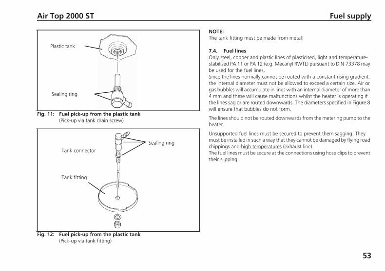
Fig. 11: Fuel pick-up from the plastic tank(Pick-up via tank drain screw)
Sealing ring
Plastic tank
Fig. 12: Fuel pick-up from the plastic tank(Pick-up via tank fitting)
Sealing ring
Tank connector
Tank fitting
Air Top 2000 ST Fuel supply
53
NOTE:The tank fitting must be made from metal!
7.4. Fuel linesOnly steel, copper and plastic lines of plasticised, light and temperature-stabilised PA 11 or PA 12 (e.g. Mecanyl RWTL) pursuant to DIN 73378 maybe used for the fuel lines.Since the lines normally cannot be routed with a constant rising gradient,the internal diameter must not be allowed to exceed a certain size. Air orgas bubbles will accumulate in lines with an internal diameter of more than4 mm and these will cause malfunctions whilst the heater is operating ifthe lines sag or are routed downwards. The diameters specified in Figure 8will ensure that bubbles do not form.
The lines should not be routed downwards from the metering pump to theheater.
Unsupported fuel lines must be secured to prevent them sagging. Theymust be installed in such a way that they cannot be damaged by flying roadchippings and high temperatures (exhaust line).The fuel lines must be secure at the connections using hose clips to preventtheir slipping.
AT2000ST_Installation_Instructions.book Page 53 Wednesday, May 29, 2013 12:54 PM
Fuel supply Air Top 2000 ST
54
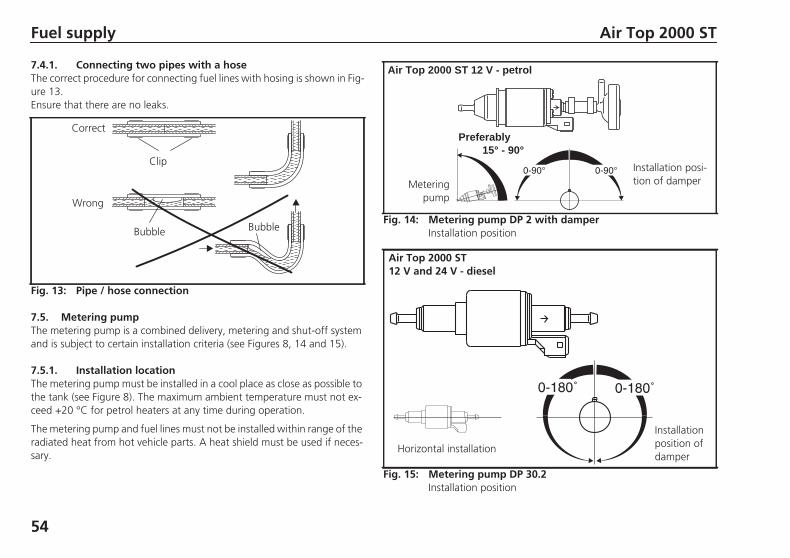
7.4.1. Connecting two pipes with a hoseThe correct procedure for connecting fuel lines with hosing is shown in Fig-ure 13.Ensure that there are no leaks.
Fig. 13: Pipe / hose connection
Clip
Bubble
Correct
Wrong
Bubble
7.5. Metering pumpThe metering pump is a combined delivery, metering and shut-off systemand is subject to certain installation criteria (see Figures 8, 14 and 15).
Fig. 14: Metering pump DP 2 with damperInstallation position
Air Top 2000 ST 12 V - petrol
Preferably15° - 90°
Installation posi-tion of damperMetering
pump
Fig. 15: Metering pump DP 30.2Installation position
Air Top 2000 ST12 V and 24 V - diesel
Installationposition ofdamper
Horizontal installation
7.5.1. Installation locationThe metering pump must be installed in a cool place as close as possible tothe tank (see Figure 8). The maximum ambient temperature must not ex-ceed +20 °C for petrol heaters at any time during operation.
The metering pump and fuel lines must not be installed within range of theradiated heat from hot vehicle parts. A heat shield must be used if neces-sary.
AT2000ST_Installation_Instructions.book Page 54 Wednesday, May 29, 2013 12:54 PM

Air Top 2000 ST Fuel supply
55
7.5.2. Installation and attachmentThe metering pump must be secured with a vibration-damping mounting(for example a rubberised clip). Its installation position is limited as shownin Figures 14 and 15 in order to ensure effective automatic bleeding.As a result of the risk of corrosion, only genuine Webasto parts may beused for the plug connections between the metering pump and the meter-ing pump wiring harness.
7.6. Fuel filterOnly a Webasto filter, order no. 487 171, is allowed to be used if the fuelis expected to be contaminated. Install vertically if possible, however atleast horizontally (check flow direction).
Fig. 16: Fuel filter
0° - 90°
AT2000ST_Installation_Instructions.book Page 55 Wednesday, May 29, 2013 12:54 PM
Combustion air supply Air Top 2000 ST
56
8 Combustion air supply
Under no circumstances may the combustion air be taken from areas oc-cupied by people. The combustion air intake opening must not point in thedirection of travel. It must be located so that it cannot become cloggedwith dirt.
NOTE:An intake silencer must be fitted if the intake hose length is shorterthan 0.6 m.
NOTE:The combustion air must be extracted using a combustion air line from aposition that is as cool as possible and protected from splashing water.Do not use an exhaust line as the combustion air line since otherwise themetering pump cable from the combustion air inlet port may be damaged.The combustion air opening must not be under the minimum water drive-through level permitted for the vehicle.
See the statutory regulations for the installation for further regulations.
AT2000ST_Installation_Instructions.book Page 56 Wednesday, May 29, 2013 12:54 PM
Air Top 2000 ST Exhaust pipe
57
9 Exhaust pipe
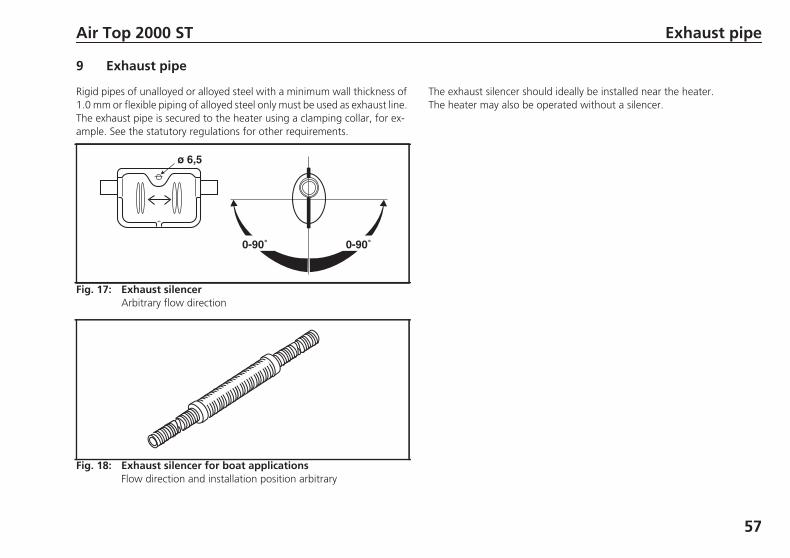
Rigid pipes of unalloyed or alloyed steel with a minimum wall thickness of1.0 mm or flexible piping of alloyed steel only must be used as exhaust line.The exhaust pipe is secured to the heater using a clamping collar, for ex-ample. See the statutory regulations for other requirements.
Fig. 17: Exhaust silencerArbitrary flow direction
Fig. 18: Exhaust silencer for boat applicationsFlow direction and installation position arbitrary
The exhaust silencer should ideally be installed near the heater.The heater may also be operated without a silencer.
AT2000ST_Installation_Instructions.book Page 57 Wednesday, May 29, 2013 12:54 PM
Combustion air inlet and exhaust lines Air Top 2000 ST
58
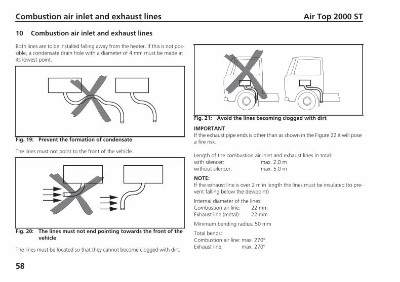
10 Combustion air inlet and exhaust lines
Both lines are to be installed falling away from the heater. If this is not pos-sible, a condensate drain hole with a diameter of 4 mm must be made atits lowest point.
Fig. 19: Prevent the formation of condensate
The lines must not point to the front of the vehicle.
Fig. 20: The lines must not end pointing towards the front of thevehicle
The lines must be located so that they cannot become clogged with dirt.
Fig. 21: Avoid the lines becoming clogged with dirt
IMPORTANTIf the exhaust pipe ends is other than as shown in the Figure 22 it will posea fire risk.
Length of the combustion air inlet and exhaust lines in total:with silencer: max. 2.0 mwithout silencer: max. 5.0 m
NOTE:If the exhaust line is over 2 m in length the lines must be insulated (to pre-vent falling below the dewpoint)
Internal diameter of the lines:Combustion air line: 22 mmExhaust line (metal): 22 mm
Minimum bending radius: 50 mm
Total bends:Combustion air line: max. 270°Exhaust line: max. 270°
AT2000ST_Installation_Instructions.book Page 58 Wednesday, May 29, 2013 12:54 PM
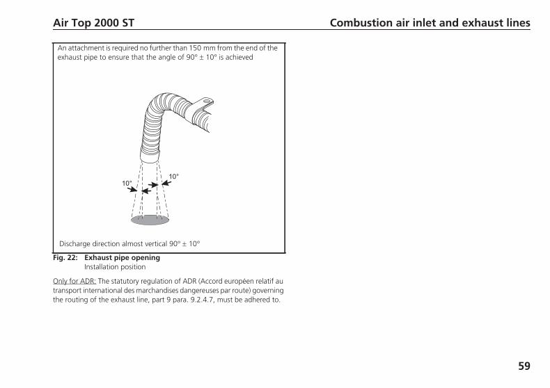
Fig. 22: Exhaust pipe openingInstallation position
An attachment is required no further than 150 mm from the end of theexhaust pipe to ensure that the angle of 90° 10° is achieved
Discharge direction almost vertical 90° 10°
Air Top 2000 ST Combustion air inlet and exhaust lines
59
Only for ADR: The statutory regulation of ADR (Accord européen relatif autransport international des marchandises dangereuses par route) governingthe routing of the exhaust line, part 9 para. 9.2.4.7, must be adhered to.
AT2000ST_Installation_Instructions.book Page 59 Wednesday, May 29, 2013 12:54 PM
Electrical connections Air Top 2000 ST
60
11 Electrical connections
All the cables that are not required must be insulated.
NOTE:If the combination timer is used, a touch-sensitive switch may be installedin the sleeping section to act as a remote control and improved conven-ience. The connections must be made as shown in the circuit diagrams inFigure 32.
The electrical connection is made as shown in the system circuit diagram(Figures 30, 31, 32 and 33).
11.1. Connection for installing the heater in a hazchem vehicle(ADR)
To install the Air Top 2000 ST D heater in hazchem vehicles, the require-ments of ADR/RID part 9 para. 9.2.4.7 – Combustion heating systems,must also be satisfied. The electrical connection is made as shown in thecircuit diagram in Figure 33 or 32.On vehicles without a power take-off the electrical connection must bemade as shown in the system wiring diagram in Figure33.
NOTE:The switch S3 must be installed in such a way that a positive potential isconnected to appropriate input of the control module when a pumping de-vice is switched on.
IMPORTANTAll ADR functions are ineffective if there is no earth at control unit inputX6/3 when the system is switched on.The control unit continues to run briefly for 40 seconds and then switchesto the "ADR lock-out" operating mode when a positive voltage is connect-ed to control unit input X6/3 (auxiliary power take-off on) or the engine isswitched off.
IMPORTANTIn accordance with the regulations of the act governing the road/rail haul-age of hazardous materials, heaters are only allowed to be taken into serv-ice with a special manually operated switch fitted in the cab.If the system is equipped with a combination timer, ensure that contact 4on the combination timer remains free. The heater can then only be takeninto service using the immediate heat button.The use of other timers in ADR vehicles is not permitted.
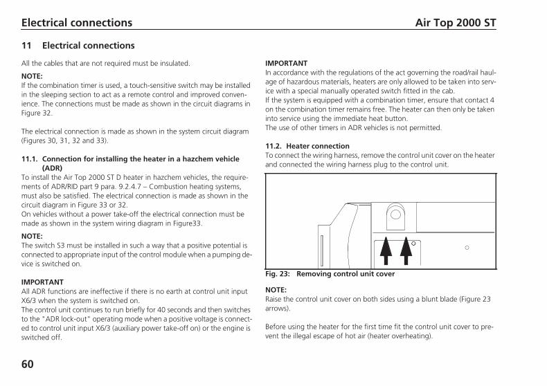
11.2. Heater connectionTo connect the wiring harness, remove the control unit cover on the heaterand connected the wiring harness plug to the control unit.
Fig. 23: Removing control unit cover
NOTE:Raise the control unit cover on both sides using a blunt blade (Figure 23arrows).
Before using the heater for the first time fit the control unit cover to pre-vent the illegal escape of hot air (heater overheating).
AT2000ST_Installation_Instructions.book Page 60 Wednesday, May 29, 2013 12:54 PM
Air Top 2000 ST Electrical connections
61
The cable passage can be placed at either the left or right side.To ensure that the cable passage in the control unit cover seals perfectly,the cable grommet is to be adjusted appropriately on the wiring harness.
11.3. Supply voltage connectionIdeally from the vehicle’s central electrical system.
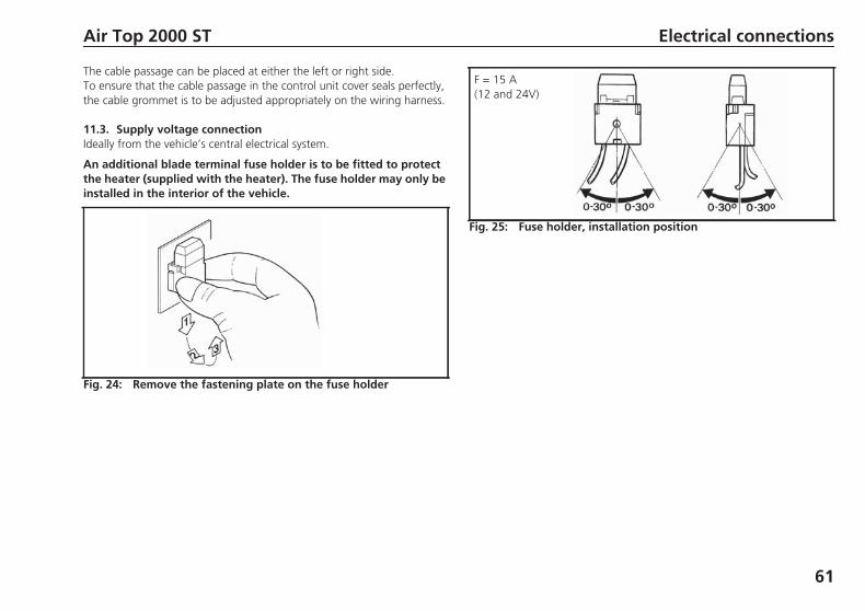
An additional blade terminal fuse holder is to be fitted to protectthe heater (supplied with the heater). The fuse holder may only beinstalled in the interior of the vehicle.
Fig. 24: Remove the fastening plate on the fuse holder
Fig. 25: Fuse holder, installation position
F = 15 A(12 and 24V)
AT2000ST_Installation_Instructions.book Page 61 Wednesday, May 29, 2013 12:54 PM
Electrical connections Air Top 2000 ST
62
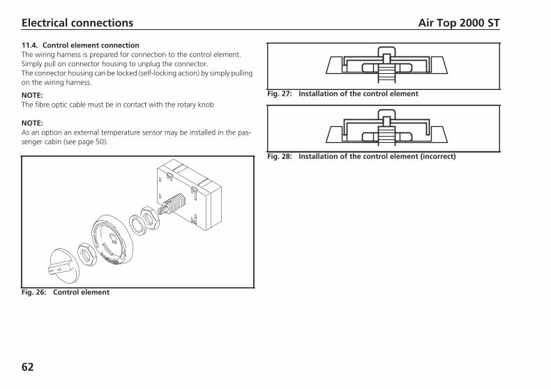
11.4. Control element connectionThe wiring harness is prepared for connection to the control element.Simply pull on connector housing to unplug the connector.The connector housing can be locked (self-locking action) by simply pullingon the wiring harness.
NOTE:The fibre optic cable must be in contact with the rotary knob
NOTE:As an option an external temperature sensor may be installed in the pas-senger cabin (see page 50).
Fig. 26: Control element
Fig. 27: Installation of the control element
Fig. 28: Installation of the control element (incorrect)
AT2000ST_Installation_Instructions.book Page 62 Wednesday, May 29, 2013 12:54 PM
Air Top 2000 ST Connection diagram/Circuit diagram
63
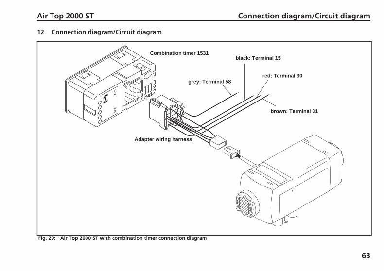
12 Connection diagram/Circuit diagram
Adapter wiring harness
red: Terminal 30grey: Terminal 58
black: Terminal 15
brown: Terminal 31
Combination timer 1531
Fig. 29: Air Top 2000 ST with combination timer connection diagram
AT2000ST_Installation_Instructions.book Page 63 Wednesday, May 29, 2013 12:54 PM
Connection diagram/Circuit diagram Air Top 2000 ST
64
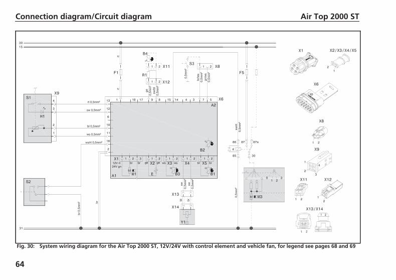
Fig. 30: System wiring diagram for the Air Top 2000 ST, 12V/24V with control element and vehicle fan, for legend see pages 68 and 69
AT2000ST_Installation_Instructions.book Page 64 Wednesday, May 29, 2013 12:54 PM
Air Top 2000 ST Connection diagram/Circuit diagram
65
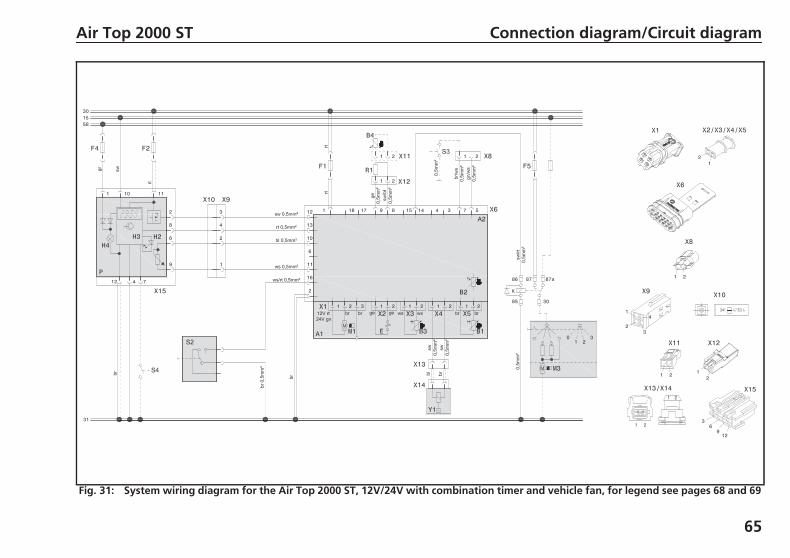
Fig. 31: System wiring diagram for the Air Top 2000 ST, 12V/24V with combination timer and vehicle fan, for legend see pages 68 and 69
AT2000ST_Installation_Instructions.book Page 65 Wednesday, May 29, 2013 12:54 PM
Connection diagram/Circuit diagram Air Top 2000 ST
66
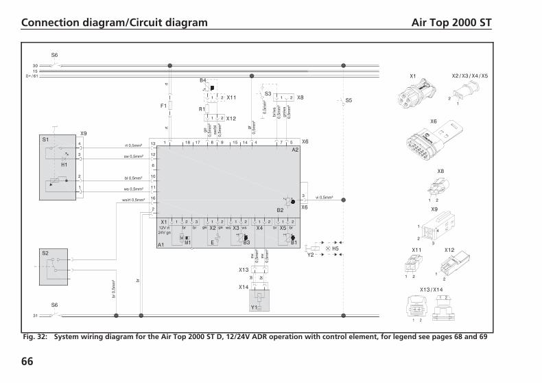
Fig. 32: System wiring diagram for the Air Top 2000 ST D, 12/24V ADR operation with control element, for legend see pages 68 and 69
AT2000ST_Installation_Instructions.book Page 66 Wednesday, May 29, 2013 12:54 PM

Air Top 2000 ST Connection diagram/Circuit diagram
67
Fig. 33: System wiring diagram for the Air Top 2000 ST, 12 V/24 V with combination timer and electrical battery isolation switch, forlegend see pages and
AT2000ST_Installation_Instructions.book Page 67 Wednesday, May 29, 2013 12:54 PM
Legend for circuit diagrams Air Top 2000 ST
68
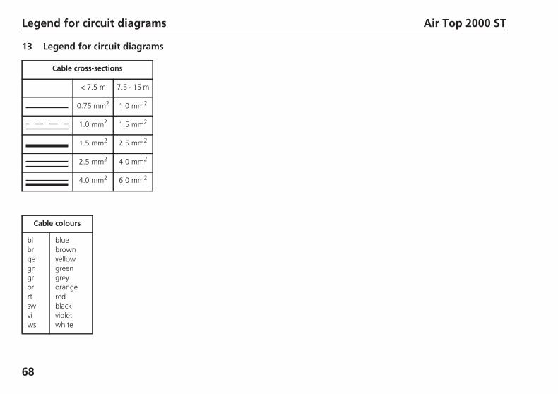
13 Legend for circuit diagrams
Cable cross-sections
< 7.5 m 7.5 - 15 m
0.75 mm2 1.0 mm2
1.0 mm2 1.5 mm2
1.5 mm2 2.5 mm2
2.5 mm2 4.0 mm2
4.0 mm2 6.0 mm2
Cable colours
blbrgegngrorrtswviws
bluebrownyellowgreengreyorangeredblackvioletwhite
AT2000ST_Installation_Instructions.book Page 68 Wednesday, May 29, 2013 12:54 PM
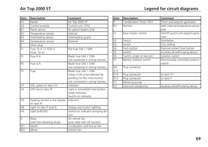
Item Description CommentA1 Heater Air Top 2000 STA2 Control module Control unit 1574B1 Flame sensor for petrol heaters onlyB2 Temperature sensor internalB3 Overheating sensor Overheating guardB4 Temperature sensor ExternalE Glow plugF1 Fuse 15 A 12 V/24 V
(max. 20 A)Flat fuse SAE J 1284
F2 Fuse 4 A Blade fuse SAE J 1284not contained in wiring harness
F4 Fuse 4 A Blade fuse SAE J 1284not contained in wiring harness
F5 Fuse Blade fuse SAE J 1284Value in [A] to be selected de-pending on line cross-sectionnot contained in wiring harness
H1 LED, green (in item S1) IndicatorH2 LED red (in item P) Light in immediate heat button,
ready indicator,Switch-on indicator
H3 Heating symbol in the display(in item P)
Indicator
H4 Light (in item P and S) Display and button lightingH5 Light bulb/LED Switch-on indicator pumping de-
viceK Relay
with free-wheeling diodefor vehicle fan(only valid with OE version)
M1 Motor Combustion and hot air fanM3 Motor Vehicle fan
P Combination Timer 1531 Timer and setpoint generatorR1 Resistor With internal temperature sensor
onlyS1 Basic heater control On/Off switch and setpoint gene-
ratorS2 Switch VentilationS3 Switch CO2 settingS4 Push button External instant heat buttonS5 Switch Auxiliary drive/Pumping deviceS6 Switch, single or two-pin Isolation switchS7 Battery isolation switch Electronically controlled isolation
switchX8-X13
Plug connector
X14 Plug connector to item Y1X15 Plug connector to item PY1 Metering pumpY2 Solenoid valve/pump Auxiliary drive/Pumping device
Air Top 2000 ST Legend for circuit diagrams
69
Item Description Comment
AT2000ST_Installation_Instructions.book Page 69 Wednesday, May 29, 2013 12:54 PM
Initial start-up Air Top 2000 ST
70
14 Initial start-up
After you have installed the heater, bleed the fuel supply system carefully.
NOTE:As a result of the low fuel consumption the heater must be switched onseveral times to fill the fuel line.Until the fuel lines have been filled the heater may switch into a fault lock-out for safety reasons - see chapter 15, "Fault lock-out".
Conduct a trial of the heater to check all the connections for leaks and toensure that they are secure. If the heater suffers a fault during operation,the fault must be located and remedied.
AT2000ST_Installation_Instructions.book Page 70 Wednesday, May 29, 2013 12:54 PM
Air Top 2000 ST Fault lock-out
71
15 Fault lock-out
The control unit has identified errors on individual heater components andfaults during the operation.
The heater is shut down (fault lock-out) if:– No or incorrect start– Temperature sensor defective– Overheating sensor interrupt or short circuit– Overheating sensor installed incorrectly– Glow plug interrupt or short circuit– Fan motor overload or blocked or short circuit or interrupt– Error in the metering pump or overheating guard circuit
(start phase only)– Undervoltage < 10.5 or overvoltage > 16 V, longer than 20 seconds (for
12 V heater)– Undervoltage < 20.5 or overvoltage > 31 V, longer than 20 seconds (for
24 V heater)– Control unit defective– Overheating– Flame monitor defective (petrol heater)
The fuel supply is stopped if the heater overheats.The heater continues to run in the same way as if it is switched off manu-ally.After it stops the control unit will be set to fault lock-out.The overheating is indicated by the indicator flashing 10 times.
Rectify the cause of the fault.
To reset the fault switch the heater on and off briefly (at least 2 seconds).If serious malfunctions such as overheating or failure to start reoccur, theheater is locked (F 12) and can be put back into service by disconnectingthe power supply with the heater switched on (e.g. by removing and re-inserting fuse).
AT2000ST_Installation_Instructions.book Page 71 Wednesday, May 29, 2013 12:54 PM
Fault lock-out Air Top 2000 ST
72
15.1. Error code output
NOTE:The error code is output if the heater is fitted with a control element afteran error has occurred by the switch-on indicator/error code indicator flash-ing. After 5 seconds of fast flashing, the error code will be output by a se-quence of long flash pulses, the number of flashes is shown in the tablebelow.
If the heater is fitted with a combination timer, an error message will ap-pear on the display of the timer after a fault occurs: If the control elementis used the error number is indicated by the indicator light flashing:F 00 Control unit error / incorrect data set / customer bus defectiveF 01 No start (no flame formation)F 02 Flame failure (repeated >3)F 03 Undervoltage or overvoltageF 04 Premature flame recognitionF 05 Flame monitor (petrol heater) interrupt or short circuitF 06 Temperature sensor interrupt or short-circuitF 07 Metering pump interrupt or short circuitF 08 Fan motor interrupt or short circuit overload or blockedF 09 Glow plug interrupt or short circuitF 10 OverheatingF 11 Overheating sensor interrupt or short circuitF 12 Heater lock-outF 14 Overheating sensor incorrect positionF 15 Setpoint generator interrupt
AT2000ST_Installation_Instructions.book Page 72 Wednesday, May 29, 2013 12:54 PM
Air Top 2000 ST Technical data
73
16 Technical data
Except where limit values are specified, the technical data refer to the usualheater tolerances of 10 % at an ambient temperature of + 20 °C and atthe rated voltage and in rated conditions.
16.1. Electrical components:Control unit, motor, metering pump, lamp in the timer and glow plug /flame monitor are designed for either 12 V or 24 V.
The timer, overheating sensor and temperature sensor component are notdependent on voltage.
16.2. Fuel for Air Top 2000 ST B (petrol):The fuel specified by the manufacturer must be used.
16.3. Fuel for Air Top 2000 ST D (diesel/ EL heating oil):The diesel fuel specified by the manufacturer in accordance with DINEN590 must be used. Class EL heating oil (not L heating oil) may also beused as long as it complies to the normal quality available on the Germanmarket pursuant to DIN 51603.<We know of no negative influences due to additives.If fuel is extracted from the vehicle’s tank, follow the additive instructionsissued by the vehicle manufacturer.
If you change to low-temperature fuel, the heater must be operated for ap-prox. 15 minutes so that the fuel system is filled with the new fuel.
The Air Top 2000 ST D heater is also licensed for use with PME (bio-diesel),which complies with DIN EN 14214.
AT2000ST_Installation_Instructions.book Page 73 Wednesday, May 29, 2013 12:54 PM
Heater Operation Air Top 2000 ST B Air Top 2000 ST DType test permit EMC
heaterE1 10R- 04 1085E1 122R- 00 0216
Model Air heater with evaporator burnerHeat output Control range 1.0 - 2.0 kW 0.9 - 2.0 kWFuel Petrol
EN 228DIN 51625
Diesel/PMEEN 590
DIN 51603DIN EN 14214
Fuel consumption Control range 0.1 - 0.2 kg/h (0.14 - 0.27 l/h) 0.1 - 0.21 kg/h (0.12 - 0.24 l/h)Rated voltage 12 V 12/24 VOperating voltage range 10.5 - 16 V 10.5 - 16 / 20.5 - 31 VRated power consumption Control range 14 - 29 WMax. ambient temperature:Heater: - Operation
- StorageMetering pump: - Operation
- StorageControl Panel: - Operation
- Storage
-40 to + 40 °C-40 to + 85 °C-40 to + 20 °C-40 to + 85 °C-40 to + 75 °C-40 to + 85 °C
Maximum combustion air inlet temperature -40 to + 20 °CAdjustment range for interior temperature Control range +5 to + 35 °CDelivery rate for hot airat fan speed
against0.5 mbar
max. 93 m3/hat 4750 rpm
CO2 in exhaust gas (permitted function range) 1 kW2 kW
5.0 - 8.0 %9.0 - 12.5 %
5.0 ... 8.0 %9.0 ... 12.5 %
Heater dimensions Length 311 2 mmWidth 120 1 mmHeight 121 1 mm
Weight 2.6 kg
Technical data Air Top 2000 ST
74
AT2000ST_Installation_Instructions.book Page 74 Wednesday, May 29, 2013 12:54 PM
Air Top 2000 ST Version
75
17 Version
Air Top 2000 ST-B (petrol)
Air heater for petrol (12 V)
Air Top 2000 ST-D (diesel)
Air heater for diesel/EL heating oil (12 or 24 V)
AT2000ST_Installation_Instructions.book Page 75 Wednesday, May 29, 2013 12:54 PM
Drilling template Air Top 2000 ST
76
18 Drilling template
Fig. 34: Drilling template
NOTE:Max. base unevenness aroundthe seal: 1 mm
Seal
AT2000ST_Installation_Instructions.book Page 76 Wednesday, May 29, 2013 12:54 PM

AT2000ST_Installation_Instructions.book Page 115 Wednesday, May 29, 2013 12:54 PM
Die Betriebsanweisung vor Inbetriebnahme des Heizgerätes unbedingt lesen.Im Fall einer mehrsprachigen Version ist Deutsch verbindlich.Die Telefonnummer des jeweiligen Landes entnehmen Sie bitte dem Webasto Servicestellenfaltblatt oder der Webseite Ihrer jeweiligen Webasto-Landesvertretung.
The Operating Instructions must be read before attempting to start up the heater.In multilingual versions the German language is binding.The telephone number of each country can be found in the Webasto service center leaflet or the website of the respective Webasto representative of your country.
De gebruiksaanwijzing moet beslist voor inbedrijfstelling van het verwarmingstoestel gelezen worden.Bij een meertalige versie is de Duitse versie bindend.Het telefoonnummer van het betreffende land kunt u vinden op het Webasto Servicepuntenoverzicht of de website van de Webastovestiging in uw land.
Iden
t-N
r.90
1029
8E•
05/1
3•
Erro
rsan
dom
issi
ons
exce
pted
•Pr
inte
din
Ger
man
y•
©W
ebas
toTh
erm
o&
Com
fort
SE,2
013
Webasto Thermo & Comfort SEPostfach 141082199 GilchingGermany
Visitors’ address:Friedrichshafener Str. 982205 GilchingGermany
Internet: www.webasto.com
Technical Extranet: http://dealers.webasto.com
Nur innerhalb von DeutschlandTel.: 0395 5592 444E-mail: [email protected]
AT2000ST_Installation_Instructions.book Page 116 Wednesday, May 29, 2013 12:54 PM