Magnetostrictive Liquid-Level Sensors with …...The Level Plus® Model MR3/4 liquid level...
8
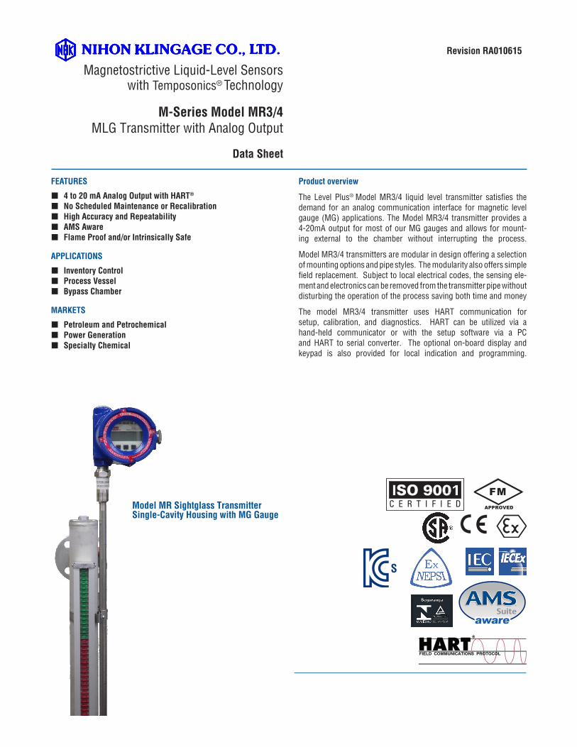
FEATURES 4 to 20 mA Analog Output with HART ® No Scheduled Maintenance or Recalibration High Accuracy and Repeatability AMS Aware Flame Proof and/or Intrinsically Safe APPLICATIONS Inventory Control Process Vessel Bypass Chamber MARKETS Petroleum and Petrochemical Power Generation Specialty Chemical Product overview The Level Plus ® Model MR3/4 liquid level transmitter satisfies the demand for an analog communication interface for magnetic level gauge (MG) applications. The Model MR3/4 transmitter provides a 4-20mA output for most of our MG gauges and allows for mount- ing external to the chamber without interrupting the process. Model MR3/4 transmitters are modular in design offering a selection of mounting options and pipe styles. The modularity also offers simple field replacement. Subject to local electrical codes, the sensing ele- ment and electronics can be removed from the transmitter pipe without disturbing the operation of the process saving both time and money The model MR3/4 transmitter uses HART communication for setup, calibration, and diagnostics. HART can be utilized via a hand-held communicator or with the setup software via a PC and HART to serial converter. The optional on-board display and keypad is also provided for local indication and programming. Magnetostrictive Liquid-Level Sensors with Temposonics ® Technology M-Series Model MR3/4 MLG Transmitter with Analog Output Data Sheet Revision RA010615 Model MR Sightglass Transmitter Single-Cavity Housing with MG Gauge FM APPROVED S
Transcript of Magnetostrictive Liquid-Level Sensors with …...The Level Plus® Model MR3/4 liquid level...
FEATURES
� 4 to 20 mA Analog Output with HART®
� No Scheduled Maintenance or Recalibration � High Accuracy and Repeatability � AMS Aware � Flame Proof and/or Intrinsically Safe
APPLICATIONS
� Inventory Control � Process Vessel � Bypass Chamber
MARKETS
� Petroleum and Petrochemical � Power Generation � Specialty Chemical
Product overview
The Level Plus® Model MR3/4 liquid level transmitter satisfies the demand for an analog communication interface for magnetic level gauge (MG) applications. The Model MR3/4 transmitter provides a 4-20mA output for most of our MG gauges and allows for mount-ing external to the chamber without interrupting the process.
Model MR3/4 transmitters are modular in design offering a selection of mounting options and pipe styles. The modularity also offers simple field replacement. Subject to local electrical codes, the sensing ele-ment and electronics can be removed from the transmitter pipe without disturbing the operation of the process saving both time and money
The model MR3/4 transmitter uses HART communication for setup, calibration, and diagnostics. HART can be utilized via a hand-held communicator or with the setup software via a PC and HART to serial converter. The optional on-board display and keypad is also provided for local indication and programming.
Magnetostrictive Liquid-Level Sensors
with Temposonics® Technology
M-Series Model MR3/4MLG Transmitter with Analog Output
Data Sheet
Revision RA010615
Model MR Sightglass TransmitterSingle-Cavity Housing with MG Gauge
FMAPPROVED
S
PRODUCT DATA SHEET
Level Plus® M-Series Model MR3/4 Sightglass Transmitter - Analog OutputProduct Data Sheet, Revision RA010615
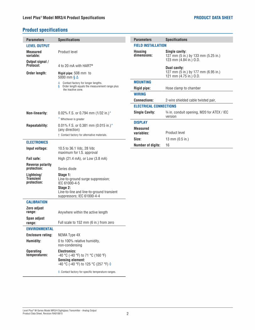
Parameters Specifications
LEVEL OUTPUT
Measured variable:
Product level
Output signal /Protocol: 4 to 20 mA with HART®
Order length: Rigid pipe: 508 mm to 5000 mm § ∆∆ Contact factory for longer lengths.§ Order length equals the measurement range plus the inactive zone.
Non-linearity: 0.02% F.S. or 0.794 mm (1/32 in.)*
* Whichever is greater
Repeatability: 0.01% F.S. or 0.381 mm (0.015 in.)*(any direction) † Contact factory for alternative materials.
ELECTRONICS
Input voltage: 10.5 to 36.1 Vdc, 28 Vdc maximum for I.S. approval
Fail safe: High (21.4 mA), or Low (3.8 mA)
Reverse polarity protection: Series diode
Lightning/Transient protection:
Stage 1: Line-to-ground surge suppression; IEC 61000-4-5Stage 2: Line-to-line and line-to-ground transient suppressors; IEC 61000-4-4
CALIBRATION
Zero adjust range: Anywhere within the active length
Span adjust range: Full scale to 152 mm (6 in.) from zero
ENVIRONMENTAL
Enclosure rating: NEMA Type 4X
Humidity: 0 to 100% relative humidity, non-condensing
Operating temperatures:
Electronics: -40 °C (-40 °F) to 71 °C (160 ºF)Sensing element: -40 °C (-40 °F) to 125 °C (257 °F) ◊
◊. Contact factory for specific temperature ranges.
Parameters Specifications
FIELD INSTALLATION
Housing dimensions:
Single cavity:127 mm (5 in.) by 133 mm (5.25 in.) 123 mm (4.84 in.) O.D.
Dual cavity:127 mm (5 in.) by 177 mm (6.95 in.) 121 mm (4.75 in.) O.D.
MOUNTING
Rigid pipe: Hose clamp to chamber
WIRING
Connections: 2-wire shielded cable twisted pair,
ELECTRICAL CONNECTIONS
Single Cavity: ¾ in. conduit opening, M20 for ATEX / IEC version
DISPLAY
Measured variables: Product level
Size: 13 mm (0.5 in.)
Number of digits: 16
Product specifications
Level Plus® Model MR3/4 Product Specifications
2
PRODUCT DATA SHEET
Level Plus® M-Series Model MR3/4 Sightglass Transmitter - Analog OutputProduct Data Sheet, Revision RA010615
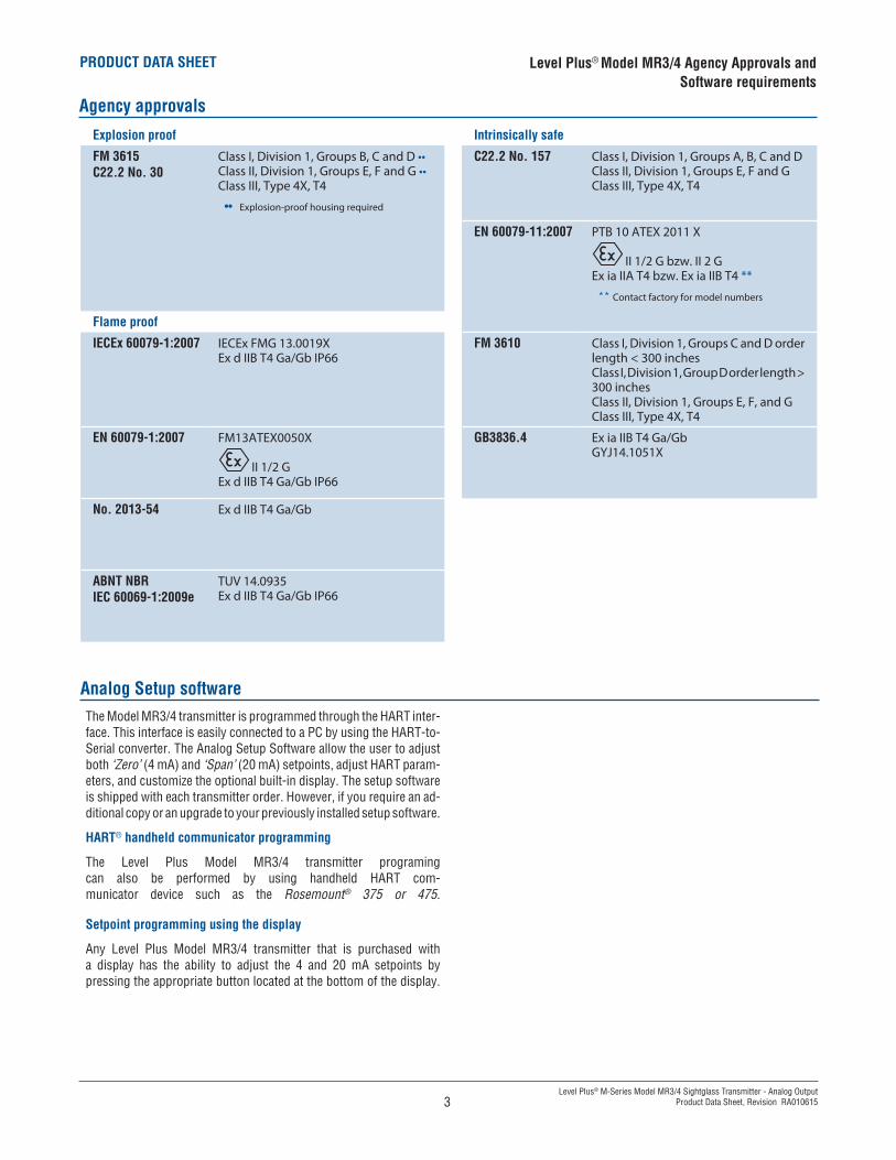
Agency approvals
Level Plus® Model MR3/4 Agency Approvals and Software requirements
3
Analog Setup softwareThe Model MR3/4 transmitter is programmed through the HART inter-face. This interface is easily connected to a PC by using the HART-to-Serial converter. The Analog Setup Software allow the user to adjust both ‘Zero’ (4 mA) and ‘Span’ (20 mA) setpoints, adjust HART param-eters, and customize the optional built-in display. The setup software is shipped with each transmitter order. However, if you require an ad-ditional copy or an upgrade to your previously installed setup software.
HART® handheld communicator programming
The Level Plus Model MR3/4 transmitter programing can also be performed by using handheld HART com-municator device such as the Rosemount® 375 or 475.
Setpoint programming using the display
Any Level Plus Model MR3/4 transmitter that is purchased with a display has the ability to adjust the 4 and 20 mA setpoints by pressing the appropriate button located at the bottom of the display.
Explosion proof Intrinsically safe
FM 3615C22.2 No. 30
Class I, Division 1, Groups B, C and D ••Class II, Division 1, Groups E, F and G ••Class III, Type 4X, T4
•• Explosion-proof housing required
C22.2 No. 157 Class I, Division 1, Groups A, B, C and DClass II, Division 1, Groups E, F and GClass III, Type 4X, T4
EN 60079-11:2007 PTB 10 ATEX 2011 X
II 1/2 G bzw. II 2 GEx ia IIA T4 bzw. Ex ia IIB T4 **
** Contact factory for model numbers
Flame proof
IECEx 60079-1:2007 IECEx FMG 13.0019XEx d IIB T4 Ga/Gb IP66
FM 3610 Class I, Division 1, Groups C and D order length < 300 inchesClass I, Division 1, Group D order length > 300 inchesClass II, Division 1, Groups E, F, and GClass III, Type 4X, T4
EN 60079-1:2007 FM13ATEX0050X
II 1/2 GEx d IIB T4 Ga/Gb IP66
GB3836.4 Ex ia IIB T4 Ga/GbGYJ14.1051X
No. 2013-54 Ex d IIB T4 Ga/Gb
ABNT NBRIEC 60069-1:2009e
TUV 14.0935Ex d IIB T4 Ga/Gb IP66
PRODUCT DATA SHEET
Level Plus® M-Series Model MR3/4 Sightglass Transmitter - Analog OutputProduct Data Sheet, Revision RA010615
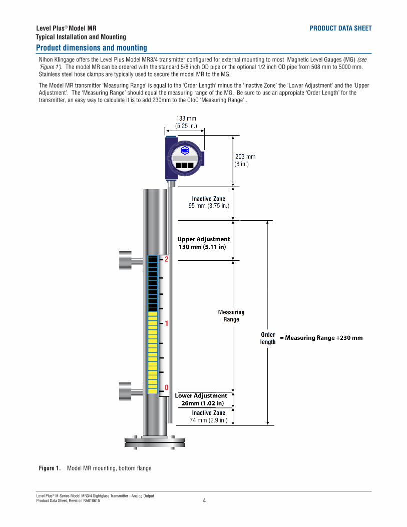
Product dimensions and mountingNihon Klingage offers the Level Plus Model MR3/4 transmitter configured for external mounting to most Magnetic Level Gauges (MG) (see 'Figure 1'). The model MR can be ordered with the standard 5/8 inch OD pipe or the optional 1/2 inch OD pipe from 508 mm to 5000 mm. Stainless steel hose clamps are typically used to secure the model MR to the MG.
The Model MR transmitter ‘Measuring Range’ is equal to the ‘Order Length’ minus the ‘Inactive Zone’ the ‘Lower Adjustment’ and the ‘Upper Adjustment’. The ‘Measuring Range’ should equal the measuring range of the MG. Be sure to use an appropiate ‘Order Length’ for the transmitter, an easy way to calculate it is to add 230mm to the CtoC ‘Measuring Range’ .
Figure 1. Model MR mounting, bottom flange
Level Plus® Model MR Typical Installation and Mounting
4
PRODUCT DATA SHEET
Level Plus® M-Series Model MR3/4 Sightglass Transmitter - Analog OutputProduct Data Sheet, Revision RA010615
Level Plus® Model MRTypical Installation and Mounting
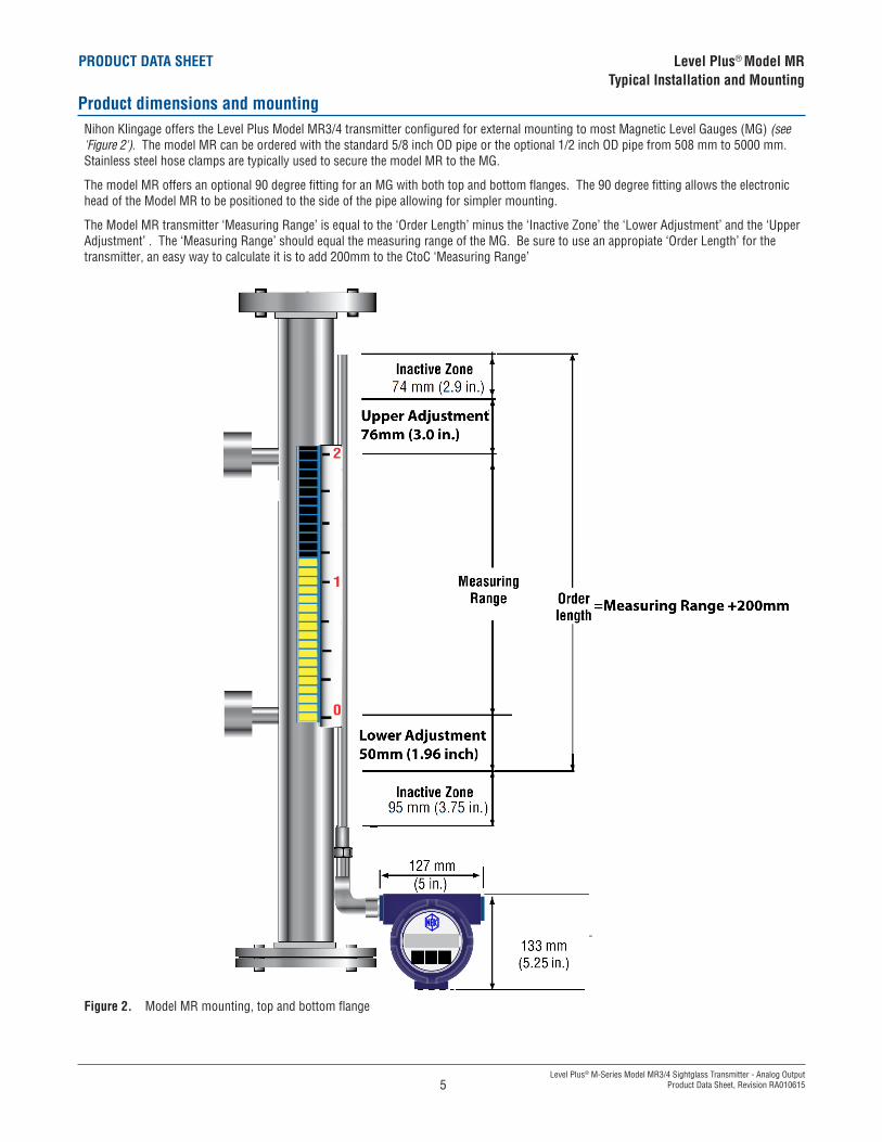
Product dimensions and mountingNihon Klingage offers the Level Plus Model MR3/4 transmitter configured for external mounting to most Magnetic Level Gauges (MG) (see 'Figure 2'). The model MR can be ordered with the standard 5/8 inch OD pipe or the optional 1/2 inch OD pipe from 508 mm to 5000 mm. Stainless steel hose clamps are typically used to secure the model MR to the MG.
The model MR offers an optional 90 degree fitting for an MG with both top and bottom flanges. The 90 degree fitting allows the electronic head of the Model MR to be positioned to the side of the pipe allowing for simpler mounting.
The Model MR transmitter ‘Measuring Range’ is equal to the ‘Order Length’ minus the ‘Inactive Zone’ the ‘Lower Adjustment’ and the ‘Upper Adjustment’ . The ‘Measuring Range’ should equal the measuring range of the MG. Be sure to use an appropiate ‘Order Length’ for the transmitter, an easy way to calculate it is to add 200mm to the CtoC ‘Measuring Range’
Figure 2. Model MR mounting, top and bottom flange
5
PRODUCT DATA SHEET
Level Plus® M-Series Model MR3/4 Sightglass Transmitter - Analog OutputProduct Data Sheet, Revision RA010615
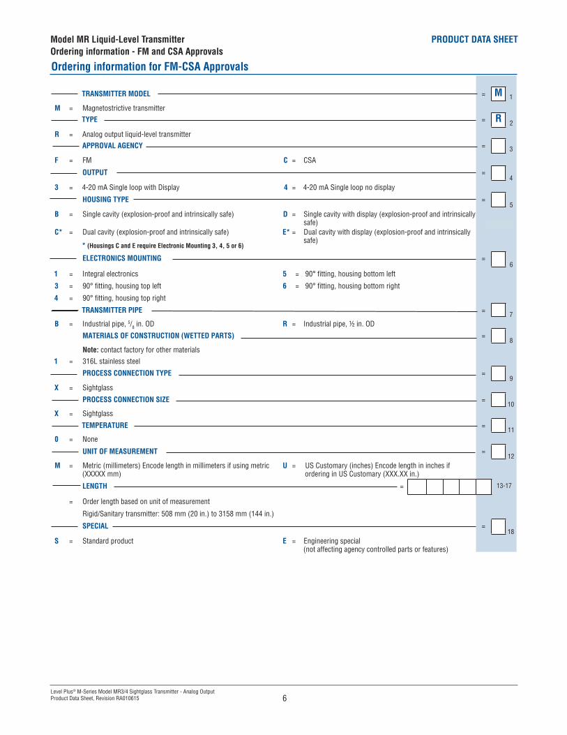
Model MR Liquid-Level TransmitterOrdering information - FM and CSA Approvals
Ordering information for FM-CSA Approvals
TRANSMITTER MODEL = M 1
M = Magnetostrictive transmitterTYPE = R 2
R = Analog output liquid-level transmitterAPPROVAL AGENCY = 3
F = FM C = CSA
OUTPUT =4
3 = 4-20 mA Single loop with Display 4 = 4-20 mA Single loop no display
HOUSING TYPE =5
B = Single cavity (explosion-proof and intrinsically safe) D = Single cavity with display (explosion-proof and intrinsically safe)
C* = Dual cavity (explosion-proof and intrinsically safe) E* = Dual cavity with display (explosion-proof and intrinsically safe)
ELECTRONICS MOUNTING =6
1 = Integral electronics 5 = 90° fitting, housing bottom left
3 = 90° fitting, housing top left 6 = 90° fitting, housing bottom right
4 = 90° fitting, housing top right
TRANSMITTER PIPE =7
B = Industrial pipe, 5/8 in. OD R = Industrial pipe, ½ in. OD
MATERIALS OF CONSTRUCTION (WETTED PARTS) =8
Note: contact factory for other materials1 = 316L stainless steel
PROCESS CONNECTION TYPE =9
X = Sightglass
PROCESS CONNECTION SIZE =10
X = Sightglass
TEMPERATURE =11
0 = None
UNIT OF MEASUREMENT =12
M = Metric (millimeters) Encode length in millimeters if using metric (XXXXX mm)
U = US Customary (inches) Encode length in inches if ordering in US Customary (XXX.XX in.)
LENGTH = 13-17
= Order length based on unit of measurement
Rigid/Sanitary transmitter: 508 mm (20 in.) to 3158 mm (144 in.)
SPECIAL =18
S = Standard product E = Engineering special (not affecting agency controlled parts or features)
6
* (Housings C and E require Electronic Mounting 3, 4, 5 or 6)
PRODUCT DATA SHEET
Level Plus® M-Series Model MR3/4 Sightglass Transmitter - Analog OutputProduct Data Sheet, Revision RA010615
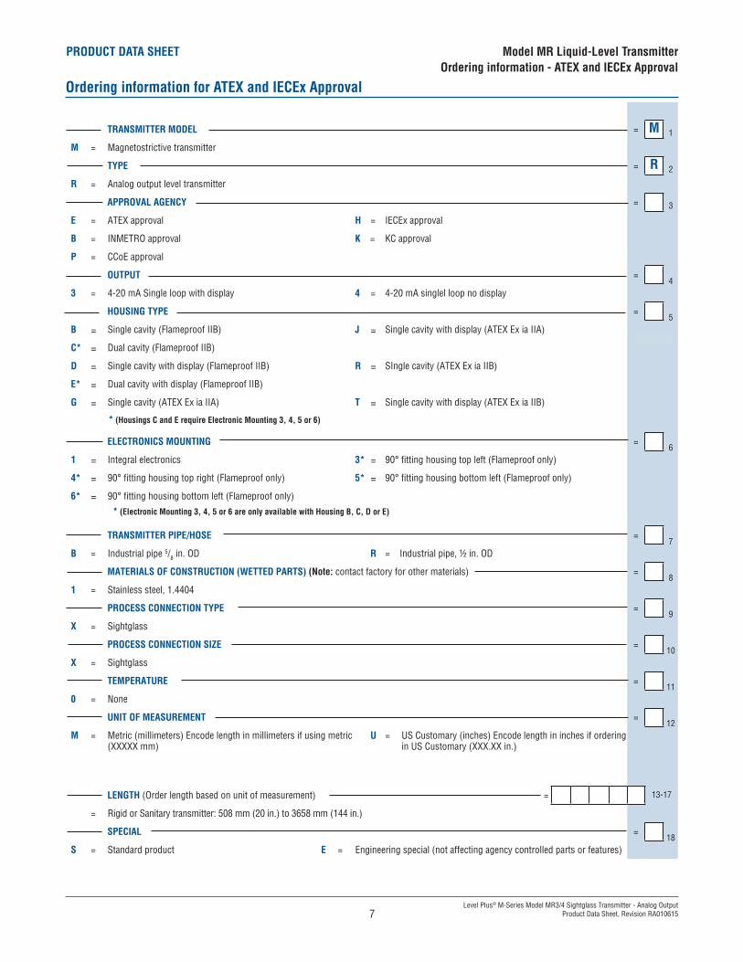
TRANSMITTER MODEL = M 1
M = Magnetostrictive transmitter
TYPE = R 2
R = Analog output level transmitter
APPROVAL AGENCY = 3
E = ATEX approval H = IECEx approval
B = INMETRO approval K = KC approval
P = CCoE approval
OUTPUT =4
3 = 4-20 mA Single loop with display 4 = 4-20 mA singlel loop no display
HOUSING TYPE =5
B = Single cavity (Flameproof IIB) J = Single cavity with display (ATEX Ex ia IIA)
C* = Dual cavity (Flameproof IIB)
D = Single cavity with display (Flameproof IIB) R = SIngle cavity (ATEX Ex ia IIB)
E* = Dual cavity with display (Flameproof IIB)
G = Single cavity (ATEX Ex ia IIA) T = Single cavity with display (ATEX Ex ia IIB)
ELECTRONICS MOUNTING =6
1 = Integral electronics 3* = 90° fitting housing top left (Flameproof only)
4* = 90° fitting housing top right (Flameproof only) 5* = 90° fitting housing bottom left (Flameproof only)
6* = 90° fitting housing bottom left (Flameproof only)
* (Electronic Mounting 3, 4, 5 or 6 are only available with Housing B, C, D or E)
TRANSMITTER PIPE/HOSE =7
B = Industrial pipe 5/8 in. OD R = Industrial pipe, ½ in. OD
MATERIALS OF CONSTRUCTION (WETTED PARTS) (Note: contact factory for other materials) =8
1 = Stainless steel, 1.4404
PROCESS CONNECTION TYPE =9
X = Sightglass
PROCESS CONNECTION SIZE =10
X = Sightglass
TEMPERATURE =11
0 = None
UNIT OF MEASUREMENT =12
M = Metric (millimeters) Encode length in millimeters if using metric (XXXXX mm)
U = US Customary (inches) Encode length in inches if ordering in US Customary (XXX.XX in.)
LENGTH (Order length based on unit of measurement) = 13-17
= Rigid or Sanitary transmitter: 508 mm (20 in.) to 3658 mm (144 in.)
SPECIAL =18
S = Standard product E = Engineering special (not affecting agency controlled parts or features)
Model MR Liquid-Level TransmitterOrdering information - ATEX and IECEx Approval
Ordering information for ATEX and IECEx Approval
7
* (Housings C and E require Electronic Mounting 3, 4, 5 or 6)
Document Part number: RA010615
LOCA
TION
S NIHON KLINGAGE CO LTD.Tokyo Sales Office6-1 Nihonbashi Yokoyama-cho, Chuo-ku, Tokyo103-0003 Japan Tel: 81 3 6661 6611 Fax: 81 3 3663 6022( Overseas Sales TEL: 81 3 6661 9330)
Osaka Sales Office2-2-3 Kyomachibori, Nishi-ku, Osaka550-0003 JapanTel: 06 6443 1866 Fax: 06 6445 2912
Soka Factory1-7-3 Aoyagi, Soka-shi, Saitama340-0002 JapanTel: 048 935 3845
Head office (Accounting Section) 1-7-3 Aoyagi, Soka-shi, Saitama340-0002 JapanTel: 048 935 3845
http://www.klingage.co.jp/
Level Plus® Model MR3/4 AccessoriesProgramming and Hardware
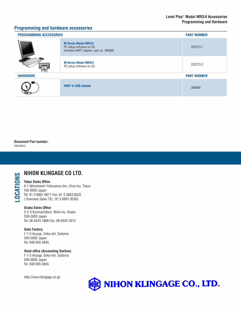
Programming and hardware accessoriesPROGRAMMING ACCESSORIES PART NUMBER
M-Series Model MR3/4PC setup software on CDIncludes HART adapter, part no. 380068
252273-1
M-Series Model MR3/4PC setup software on CD 252273-2
HARDWARE PART NUMBER
HART to USB adapter 380068