Manual 750-555 - VENDOMOTICAvendomotica.com/imgcsv/Manual salida analogica de 4 canales 4-20 … ·...
48
Manual WAGO-I/O-SYSTEM 750 4 AO 4-20 mA 750-555 4-Channel Analog Output Module 4-20 mA Version 1.1.0
Transcript of Manual 750-555 - VENDOMOTICAvendomotica.com/imgcsv/Manual salida analogica de 4 canales 4-20 … ·...
Pos: 2 /D okumentati on allgemein/Ei nband/Ei nband H andbuch - Deckbl att ohne Variantenfel d (Standar d) @ 9\mod_1285229289866_0.docx @ 64941 @ @ 1
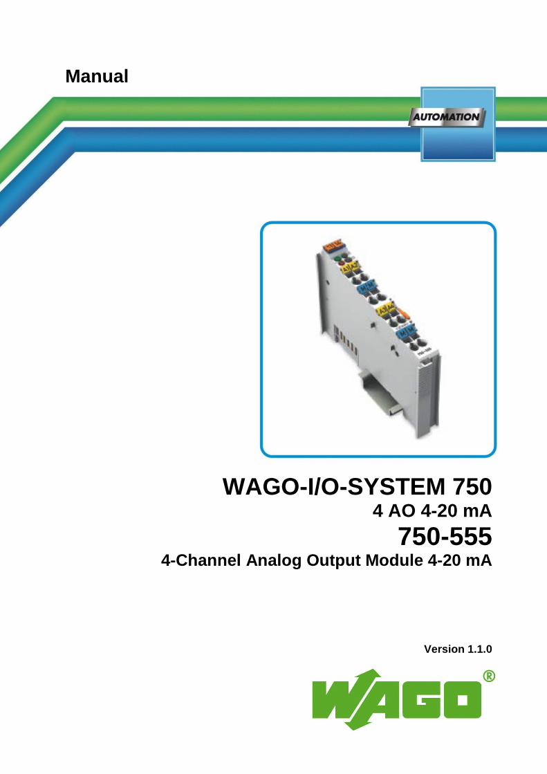
Manual
WAGO-I/O-SYSTEM 750 4 AO 4-20 mA
750-555 4-Channel Analog Output Module 4-20 mA
Version 1.1.0 Pos: 3 /Alle Serien (Allgemeine M odul e)/Hinweise zur Dokumentation/Impressum für Standardhandbücher - allg. Angaben, Anschriften, Tel efonnummer n und E-Mail-Adressen @ 3\mod_1219151118203_21.docx @ 21060 @ @ 1
2 WAGO-I/O-SYSTEM 750 750-555 4 AO 4-20 mA
Manual Version 1.1.0
© 2014 by WAGO Kontakttechnik GmbH & Co. KG All rights reserved.
WAGO Kontakttechnik GmbH & Co. KG
Hansastraße 27 D-32423 Minden
Phone: +49 (0) 571/8 87 – 0 Fax: +49 (0) 571/8 87 – 1 69
E-Mail: [email protected]
Web: http://www.wago.com
Technical Support
Phone: +49 (0) 571/8 87 – 5 55 Fax: +49 (0) 571/8 87 – 85 55
E-Mail: [email protected]
Every conceivable measure has been taken to ensure the accuracy and completeness of this documentation. However, as errors can never be fully excluded, we always appreciate any information or suggestions for improving the documentation.
E-Mail: [email protected]
We wish to point out that the software and hardware terms as well as the trademarks of companies used and/or mentioned in the present manual are generally protected by trademark or patent.
=== Ende der Liste für Textmar ke Ei nband_vorne ===
WAGO-I/O-SYSTEM 750 Table of Contents 3 750-555 4 AO 4-20 mA
Manual Version 1.1.0
Pos: 5 /D okumentati on allgemein/Verzeichnisse/Inhaltsverzeichnis - Ü berschrif t oG und Verzei chnis @ 3\mod_1219151230875_21.docx @ 21063 @ @ 1
Table of Contents 1 Notes about this Documentation ................................................................. 5 1.1 Validity of this Documentation ................................................................. 5 1.2 Copyright ................................................................................................... 5 1.3 Symbols ..................................................................................................... 6 1.4 Number Notation ....................................................................................... 8 1.5 Font Conventions ...................................................................................... 8
2 Important Notes ........................................................................................... 9 2.1 Legal Bases ............................................................................................... 9 2.1.1 Subject to Changes ............................................................................... 9 2.1.2 Personnel Qualifications ....................................................................... 9 2.1.3 Use of the WAGO-I/O-SYSTEM 750 in Compliance with Underlying
Provisions ............................................................................................. 9 2.1.4 Technical Condition of Specified Devices ......................................... 10 2.2 Safety Advice (Precautions) .................................................................... 11
3 Device Description ..................................................................................... 13 3.1 View ........................................................................................................ 15 3.2 Connectors ............................................................................................... 16 3.2.1 Data Contacts/Internal Bus ................................................................. 16 3.2.2 Power Jumper Contacts/Field Supply ................................................ 17 3.2.3 CAGE CLAMP® Connectors ............................................................. 19 3.3 Display Elements .................................................................................... 20 3.4 Operating Elements ................................................................................. 20 3.5 Schematic Diagram ................................................................................. 21 3.6 Technical Data ........................................................................................ 22 3.6.1 Device Data ........................................................................................ 22 3.6.2 Power Supply...................................................................................... 22 3.6.3 Communication .................................................................................. 22 3.6.4 Outputs ............................................................................................... 22 3.6.5 Connection Type ................................................................................ 23 3.6.6 Climatic Environmental Conditions ................................................... 23 3.7 Approvals ................................................................................................ 24 3.8 Standards and Guidelines ........................................................................ 26
4 Process Image ............................................................................................. 27
5 Mounting ..................................................................................................... 28 5.1 Mounting Sequence ................................................................................. 28 5.2 Inserting and Removing Devices ............................................................ 29 5.2.1 Inserting the I/O Module .................................................................... 29 5.2.2 Removing the I/O Module .................................................................. 30
6 Connect Devices ......................................................................................... 31 6.1 Connecting a Conductor to the CAGE CLAMP® ................................... 31 6.2 Connection Examples .............................................................................. 32
7 Use in Hazardous Environments .............................................................. 33 7.1 Marking Configuration Examples ........................................................... 34 7.1.1 Marking for Europe according to ATEX and IEC-Ex ........................ 34
4 Table of Contents WAGO-I/O-SYSTEM 750 750-555 4 AO 4-20 mA
Manual Version 1.1.0
7.1.2 Marking for America according to NEC 500 ..................................... 39 7.2 Installation Regulations ........................................................................... 40 7.2.1 Special Conditions for Safe Use (ATEX Certificate TÜV 07 ATEX
554086 X) ........................................................................................... 41 7.2.2 Special Conditions for Safe Use (ATEX Certificate TÜV 12 ATEX
106032 X) ........................................................................................... 42
=== Ende der Liste für Textmar ke Verzeichnis_vor ne ===

WAGO-I/O-SYSTEM 750 Notes about this Documentation 5 750-555 4 AO 4-20 mA
Manual Version 1.1.0
Pos: 7 /Alle Serien (Allgemeine M odul e)/Überschriften für all e Serien/Hi nweis zur Dokumentation/Hinweise zu dieser D okumentati on - Überschrift 1 @ 4\mod_1237987661750_21.docx @ 29029 @ 1 @ 1
1 Notes about this Documentation Pos: 8 /Alle Serien (Allgemeine M odul e)/Hinweise zur Dokumentation/Hi nweise/Hi nweis : D okumentation aufbewahr en @ 4\mod_1237987339812_21.docx @ 29026 @ @ 1
Keep this documentation! The operating instructions are part of the product and shall be kept for the entire lifetime of the product. They shall be transferred to each subsequent user of the product. Care must also be taken to ensure that any supplement to these instructions are included, if applicable.
Pos: 9 /Alle Serien (Allgemeine M odul e)/Überschriften für all e Serien/Hi nweis zur Dokumentation/Gültig keitsber eich - Überschrift 2 @ 12\mod_1338912448776_21.docx @ 96469 @ 2 @ 1
1.1 Validity of this Documentation Pos: 10 /Serie 750 ( WAGO-I/O-SYSTEM)/Hi nweise zur D okumentati on/Gültigkeitsbereich/Gültig keitsber eich Dokumentation Buskl emme 750- xxxx, ohne Variantenangabe @ 14\mod_1358944037947_21.docx @ 109346 @ @ 1
This documentation is only applicable to the I/O module 750-555 (4 AO 4-20 mA).
Pos: 11 /Serie 750 ( WAGO-I/O-SYSTEM)/Hi nweise zur D okumentati on/Hi nweise/Achtung: Hinweis zur D okumentati on Buskl emmen 750- xxxx @ 4\mod_1237986979656_21.docx @ 29023 @ @ 1
The I/O module 750-555 shall only be installed and operated according to the instructions in this manual and in the manual for the used fieldbus coupler/controller.
Consider power layout of the WAGO-I/O-SYSTEM 750! In addition to these operating instructions, you will also need the manual for the used fieldbus coupler/controller, which can be downloaded at www.wago.com. There, you can obtain important information including information on electrical isolation, system power and supply specifications.
Pos: 12.1 /All e Seri en ( Allgemei ne Module)/Hi nweise zur D okumentati on/Urheberschutz ausführlich @ 4\mod_1235565145234_21.docx @ 27691 @ 2 @ 1
1.2 Copyright This Manual, including all figures and illustrations, is copyright-protected. Any further use of this Manual by third parties that violate pertinent copyright provisions is prohibited. Reproduction, translation, electronic and phototechnical filing/archiving (e.g., photocopying) as well as any amendments require the written consent of WAGO Kontakttechnik GmbH & Co. KG, Minden, Germany. Non-observance will involve the right to assert damage claims.
Pos: 12.2 /Dokumentation allgemei n/Glieder ungselemente/---Seitenwechsel--- @ 3\mod_1221108045078_0.docx @ 21810 @ @ 1
6 Notes about this Documentation WAGO-I/O-SYSTEM 750 750-555 4 AO 4-20 mA
Manual Version 1.1.0
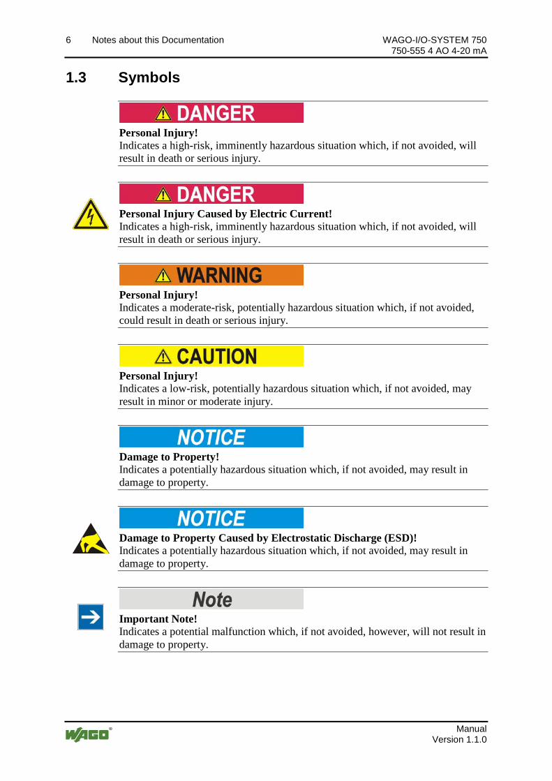
Pos: 12.3 /All e Seri en ( Allgemei ne Module)/Ü berschriften für alle Serien/Hinweis zur D okumentati on/Symbole - Ü berschrif t 2 @ 13\mod_1351068042408_21.docx @ 105270 @ 2 @ 1
1.3 Symbols Pos: 12.4.1 /All e Serien ( Allgemei ne Module)/Wichtige Erläuterungen/Sicherheits- und sons tige Hinweise/Gefahr/Gefahr: _War nung vor Personenschäden allgemei n_ - Erl äuter ung @ 13\mod_1343309450020_21.docx @ 101029 @ @ 1
Personal Injury! Indicates a high-risk, imminently hazardous situation which, if not avoided, will result in death or serious injury.
Pos: 12.4.2 /All e Serien ( Allgemei ne Module)/Wichtige Erläuterungen/Sicherheits- und sons tige Hinweise/Gefahr/Gefahr: _War nung vor Personenschäden durch elektrischen Strom_ - Erläuterung @ 13\mod_1343309694914_21.docx @ 101030 @ @ 1
Personal Injury Caused by Electric Current! Indicates a high-risk, imminently hazardous situation which, if not avoided, will result in death or serious injury.
Pos: 12.4.3 /All e Serien ( Allgemei ne Module)/Wichtige Erläuterungen/Sicherheits- und sons tige Hinweise/Warnung/Warnung: _Warnung vor Personenschäden allgemei n_ - Erläuterung @ 13\mod_1343309877041_21.docx @ 101035 @ @ 1
Personal Injury! Indicates a moderate-risk, potentially hazardous situation which, if not avoided, could result in death or serious injury.
Pos: 12.4.4 /All e Serien ( Allgemei ne Module)/Wichtige Erläuterungen/Sicherheits- und sons tige Hinweise/Vorsicht/Vorsicht: _War nung vor Personenschäden allgemein_ - Erläuterung @ 13\mod_1343310028762_21.docx @ 101038 @ @ 1
Personal Injury! Indicates a low-risk, potentially hazardous situation which, if not avoided, may result in minor or moderate injury.
Pos: 12.4.5 /All e Serien ( Allgemei ne Module)/Wichtige Erläuterungen/Sicherheits- und sons tige Hinweise/Achtung/Achtung: _War nung vor Sachschäden allgemein_ - Erläuterung @ 13\mod_1343310134623_21.docx @ 101041 @ @ 1
Damage to Property! Indicates a potentially hazardous situation which, if not avoided, may result in damage to property.
Pos: 12.4.6 /All e Serien ( Allgemei ne Module)/Wichtige Erläuterungen/Sicherheits- und sons tige Hinweise/Achtung/Achtung: _War nung vor Sachschäden durch elektr ostatische Aufladung_ - Erläuterung @ 13\mod_1343310227702_21.docx @ 101044 @ @ 1
Damage to Property Caused by Electrostatic Discharge (ESD)! Indicates a potentially hazardous situation which, if not avoided, may result in damage to property.
Pos: 12.4.7 /All e Serien ( Allgemei ne Module)/Wichtige Erläuterungen/Sicherheits- und sons tige Hinweise/Hi nweis /Hinweis: _Wichtiger Hi nweis allgemein_ - Erläuterung @ 13\mod_1343310326906_21.docx @ 101047 @ @ 1
Important Note! Indicates a potential malfunction which, if not avoided, however, will not result in damage to property.
Pos: 12.4.8 /All e Serien ( Allgemei ne Module)/Wichtige Erläuterungen/Sicherheits- und sons tige Hinweise/Infor mation/Infor mation: _Weiter e Infor mation allgemei n_ - Erl äuter ung @ 13\mod_1343310439814_21.docx @ 101051 @ @ 1
WAGO-I/O-SYSTEM 750 Notes about this Documentation 7 750-555 4 AO 4-20 mA
Manual Version 1.1.0
Additional Information: Refers to additional information which is not an integral part of this documentation (e.g., the Internet).
Pos: 12.5 /Dokumentation allgemei n/Glieder ungselemente/---Seitenwechsel--- @ 3\mod_1221108045078_0.docx @ 21810 @ @ 1
8 Notes about this Documentation WAGO-I/O-SYSTEM 750 750-555 4 AO 4-20 mA
Manual Version 1.1.0
Pos: 12.6 /All e Seri en ( Allgemei ne Module)/Hi nweise zur D okumentati on/Zahlensysteme @ 3\mod_1221059454015_21.docx @ 21711 @ 2 @ 1
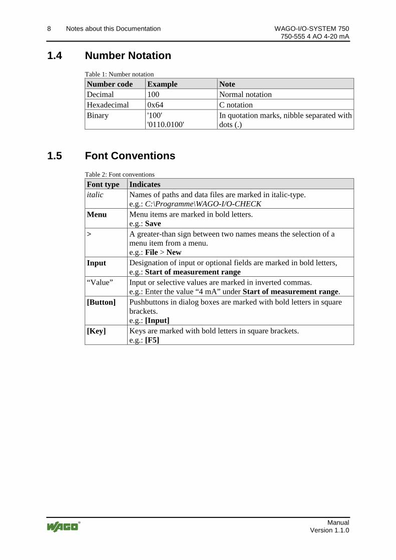
1.4 Number Notation Table 1: Number notation Number code Example Note Decimal 100 Normal notation Hexadecimal 0x64 C notation Binary '100'
'0110.0100' In quotation marks, nibble separated with dots (.)
Pos: 12.7 /All e Seri en ( Allgemei ne Module)/Hi nweise zur D okumentati on/Schriftkonventi onen @ 3\mod_1221059521437_21.docx @ 21714 @ 2 @ 1
1.5 Font Conventions Table 2: Font conventions Font type Indicates italic Names of paths and data files are marked in italic-type.
e.g.: C:\Programme\WAGO-I/O-CHECK Menu Menu items are marked in bold letters.
e.g.: Save > A greater-than sign between two names means the selection of a
menu item from a menu. e.g.: File > New
Input Designation of input or optional fields are marked in bold letters, e.g.: Start of measurement range
“Value” Input or selective values are marked in inverted commas. e.g.: Enter the value “4 mA” under Start of measurement range.
[Button] Pushbuttons in dialog boxes are marked with bold letters in square brackets. e.g.: [Input]
[Key] Keys are marked with bold letters in square brackets. e.g.: [F5]
Pos: 13 /D okumentation allgemei n/Glieder ungselemente/---Seitenwechsel--- @ 3\mod_1221108045078_0.docx @ 21810 @ @ 1

WAGO-I/O-SYSTEM 750 Important Notes 9 750-555 4 AO 4-20 mA
Manual Version 1.1.0
Pos: 14 /All e Seri en (Allgemei ne Module)/Ü berschrif ten für alle Serien/Wichtige Erläuterungen/Wichtige Erläuter ungen - Überschrift 1 @ 4\mod_1241428899156_21.docx @ 32170 @ 1 @ 1
2 Important Notes Pos: 15.1 /All e Seri en ( Allgemei ne Dokumente) ( Allgemei ne Module)/Wichtige Erläuterungen/Einl eitung Wichtige Erläuterungen @ 3\mod_1221059818031_21.docx @ 21717 @ @ 1
This section includes an overall summary of the most important safety requirements and notes that are mentioned in each individual section. To protect your health and prevent damage to devices as well, it is imperative to read and carefully follow the safety guidelines.
Pos: 15.2 /All e Seri en ( Allgemei ne Module)/Ü berschriften für alle Serien/Wichtige Erläuter ungenR echtliche Gr undlag en - Überschrift 2 @ 3\mod_1221060626343_21.docx @ 21726 @ 2 @ 1
2.1 Legal Bases Pos: 15.3 /All e Seri en ( Allgemei ne Dokumente) ( Allgemei ne Module)/Wichtige Erläuterungen/Änderungsvor behalt - Ü berschrift 3 und Inhalt @ 3\mod_1221060036484_21.docx @ 21720 @ 3 @ 1
2.1.1 Subject to Changes
WAGO Kontakttechnik GmbH & Co. KG reserves the right to provide for any alterations or modifications that serve to increase the efficiency of technical progress. WAGO Kontakttechnik GmbH & Co. KG owns all rights arising from the granting of patents or from the legal protection of utility patents. Third-party products are always mentioned without any reference to patent rights. Thus, the existence of such rights cannot be excluded.
Pos: 15.4 /Serie 750 (WAGO-I/O-SYSTEM)/Wichtige Erläuterungen/Personalqualifi kationPersonalqualifi kation 750- xxxx - Ü berschrift 3 und Inhalt @ 3\mod_1224061208046_21.docx @ 24063 @ 3 @ 1
2.1.2 Personnel Qualifications
All sequences implemented on WAGO-I/O-SYSTEM 750 devices may only be carried out by electrical specialists with sufficient knowledge in automation. The specialists must be familiar with the current norms and guidelines for the devices and automated environments.
All changes to the coupler or controller should always be carried out by qualified personnel with sufficient skills in PLC programming.
Pos: 15.5 /Serie 750 (WAGO-I/O-SYSTEM)/Wichtige Erläuterungen/Bes timmungsgemäße Verwendung Bes ti mmungsgemäße Verwendung 750-xxxx - Ü berschrif t 3 und Inhal t @ 3\mod_1224064151234_21.docx @ 24070 @ 3 @ 1
2.1.3 Use of the WAGO-I/O-SYSTEM 750 in Compliance with Underlying Provisions
Fieldbus couplers, fieldbus controllers and I/O modules found in the modular WAGO-I/O-SYSTEM 750 receive digital and analog signals from sensors and transmit them to actuators or higher-level control systems. Using programmable controllers, the signals can also be (pre-) processed.
The devices have been developed for use in an environment that meets the IP20 protection class criteria. Protection against finger injury and solid impurities up to 12.5 mm diameter is assured; protection against water damage is not ensured. Unless otherwise specified, operation of the devices in wet and dusty environments is prohibited.
Operating the WAGO-I/O-SYSTEM 750 devices in home applications without further measures is only permitted if they meet the emission limits (emissions of interference) according to EN 61000-6-3. You will find the relevant information in the section “Device Description” > “Standards and Guidelines” in the manual for the used fieldbus coupler/controller.
10 Important Notes WAGO-I/O-SYSTEM 750 750-555 4 AO 4-20 mA
Manual Version 1.1.0
Appropriate housing (per 94/9/EG) is required when operating the WAGO-I/O-SYSTEM 750 in hazardous environments. Please note that a prototype test certificate must be obtained that confirms the correct installation of the system in a housing or switch cabinet.
Pos: 15.6 /All e Seri en ( Allgemei ne Dokumente) ( Allgemei ne Module)/Wichtige Erläuterungen/Technischer Zustand der Geräte - Überschrift 3 und Inhalt @ 3\mod_1221060446109_21.docx @ 21723 @ 3 @ 1
2.1.4 Technical Condition of Specified Devices
The devices to be supplied ex works are equipped with hardware and software configurations, which meet the individual application requirements. WAGO Kontakttechnik GmbH & Co. KG will be exempted from any liability in case of changes in hardware or software as well as to non-compliant usage of devices.
Please send your request for modified and new hardware or software configurations directly to WAGO Kontakttechnik GmbH & Co. KG.
Pos: 15.7 /Dokumentation allgemei n/Glieder ungselemente/---Seitenwechsel--- @ 3\mod_1221108045078_0.docx @ 21810 @ @ 1
WAGO-I/O-SYSTEM 750 Important Notes 11 750-555 4 AO 4-20 mA
Manual Version 1.1.0
Pos: 15.8 /All e Seri en ( Allgemei ne Module)/Ü berschriften für alle Serien/Wichtige Erläuter ungenSicher hei tshi nweise - Überschrift 2 @ 6\mod_1260180299987_21.docx @ 46724 @ 2 @ 1
2.2 Safety Advice (Precautions) Pos: 15.9 /All e Seri en ( Allgemei ne Dokumente) ( Allgemei ne Module)/Wichtige Erläuterungen/Sicherheitshi nweise/Einl eitung Sicherheitshinweise H ardware @ 6\mod_1260180170493_21.docx @ 46720 @ @ 1
For installing and operating purposes of the relevant device to your system the following safety precautions shall be observed:
Pos: 15.10.1 /Alle Serien (Allgemeine D okumente) (Allgemeine M odul e)/Wichtige Erläuter ungen/Sicherheitshinweise/Gefahr /Gefahr: Nicht an Geräten unter Spannung ar beiten! @ 6\mod_1260180365327_21.docx @ 46727 @ @ 1
Do not work on devices while energized! All power sources to the device shall be switched off prior to performing any installation, repair or maintenance work.
Pos: 15.10.2 /Serie 750 ( WAGO-I/O- SYSTEM)/Wichtig e Erl äuter ung en/Sicher hei ts- und sonstige Hi nweise/Gefahr/Gefahr: Ei nbau 0750- xxxx nur i n Gehäusen, Schränken oder el ektrischen Betriebsräumen! @ 6\mod_1260180556692_21.docx @ 46731 @ @ 1
Installation only in appropriate housings, cabinets or in electrical operation rooms! The WAGO-I/O-SYSTEM 750 and its components are an open system. As such, install the system and its components exclusively in appropriate housings, cabinets or in electrical operation rooms. Allow access to such equipment and fixtures to authorized, qualified staff only by means of specific keys or tools.
Pos: 15.10.3 /Alle Serien (Allgemeine D okumente) (Allgemeine M odul e)/Wichtige Erläuter ungen/Sicherheitshinweise/Gefahr /Gefahr: Unfall verhütungsvorschriften beachten! @ 6\mod_1260180657000_21.docx @ 46735 @ @ 1
Pos: 15.10.4 /Alle Serien (Allgemeine D okumente) (Allgemeine M odul e)/Wichtige Erläuter ungen/Sicherheitshinweise/Gefahr /Gefahr: Auf normg erechten Anschluss achten! @ 6\mod_1260180753479_21.docx @ 46739 @ @ 1 Pos : 15.11.1 /Alle Serien (Allgemeine D okumente) (Allgemeine M odul e)/Wichtige Erläuter ungen/Sicherheitshinweise/Achtung/Achtung: Defekte oder beschädigte Ger äte aus tauschen! @ 6\mod_1260180857358_21.docx @ 46743 @ @ 1
Replace defective or damaged devices! Replace defective or damaged device/module (e.g., in the event of deformed contacts), since the long-term functionality of device/module involved can no longer be ensured.
Pos: 15.11.2 /Alle Serien (Allgemeine D okumente) (Allgemeine M odul e)/Wichtige Erläuter ungen/Sicherheitshinweise/Achtung/Achtung: Geräte vor kriechenden und isolier enden Stoffen schützen! @ 6\mod_1260181036216_21.docx @ 46747 @ @ 1
Protect the components against materials having seeping and insulating properties! The components are not resistant to materials having seeping and insulating properties such as: aerosols, silicones and triglycerides (found in some hand creams). If you cannot exclude that such materials will appear in the component environment, then install the components in an enclosure being resistant to the above-mentioned materials. Clean tools and materials are imperative for handling devices/modules.
Pos: 15.11.3 /Alle Serien (Allgemeine D okumente) (Allgemeine M odul e)/Wichtige Erläuter ungen/Sicherheitshinweise/Achtung/Achtung: Rei nigung nur mit zul ässigen M aterialien! @ 6\mod_1260181203293_21.docx @ 46751 @ @ 1
Clean only with permitted materials! Clean soiled contacts using oil-free compressed air or with ethyl alcohol and leather cloths.
Pos: 15.11.4 /Alle Serien (Allgemeine D okumente) (Allgemeine M odul e)/Wichtige Erläuter ungen/Sicherheitshinweise/Achtung/Achtung: Kei n Kontaktspray verwenden! @ 6\mod_1260181290808_21.docx @ 46755 @ @ 1
12 Important Notes WAGO-I/O-SYSTEM 750 750-555 4 AO 4-20 mA
Manual Version 1.1.0
Do not use any contact spray! Do not use any contact spray. The spray may impair contact area functionality in connection with contamination.
Pos: 15.11.5 /Alle Serien (Allgemeine D okumente) (Allgemeine M odul e)/Wichtige Erläuter ungen/Sicherheitshinweise/Achtung/Achtung: Verpol ung ver mei den! @ 6\mod_1260184045744_21.docx @ 46767 @ @ 1
Do not reverse the polarity of connection lines! Avoid reverse polarity of data and power supply lines, as this may damage the devices involved.
Pos: 15.11.6 /Alle Serien (Allgemeine D okumente) (Allgemeine M odul e)/Wichtige Erläuter ungen/Sicherheitshinweise/Achtung/Achtung: El ektr ostatische Entl adung vermeiden! @ 6\mod_1260181364729_21.docx @ 46759 @ @ 1
Avoid electrostatic discharge! The devices are equipped with electronic components that may be destroyed by electrostatic discharge when touched. Please observe the safety precautions against electrostatic discharge per DIN EN 61340-5-1/-3. When handling the devices, please ensure that environmental factors (personnel, work space and packaging) are properly grounded.
Pos: 16 /D okumentation allgemei n/Glieder ungselemente/---Seitenwechsel--- @ 3\mod_1221108045078_0.docx @ 21810 @ @ 1
WAGO-I/O-SYSTEM 750 Device Description 13 750-555 4 AO 4-20 mA
Manual Version 1.1.0
Pos: 17 /All e Seri en (Allgemei ne Module)/Ü berschrif ten für alle Serien/Gerätebeschreibung/Gerätebeschr eibung - Überschrift 1 @ 3\mod_1233756084656_21.docx @ 27096 @ 1 @ 1
3 Device Description Pos: 18.1.1 /Serie 750 (WAGO-I/O-SYSTEM)/Gerätebeschrei bung/Ei nlei tung/Anwendung/AO/Anwendung 750-05xx AO (4...20mA) @ 5\mod_1247047051401_21.docx @ 36841 @ @ 1
The analog output module 750-555 (4 AO 4-20 mA) generates a standardized signal of 4 … 20 mA for the field area.
Pos: 18.1.2 /Serie 750 (WAGO-I/O-SYSTEM)/Gerätebeschrei bung/Ei nlei tung/I/O-Beschrei bung/AO/I/O- Beschr eibung 750- 05xx 4 AO 2-Leiter (AO1...AO4 und Masse) @ 5\mod_1247053300854_21.docx @ 36880 @ @ 1
The I/O module has 4 output channels, making direct wiring of four 2-wire actuators possible. The actuators are connected to CAGE CLAMP® connectors AO 1 and Ground or AO 2, AO 3, AO 4 and respective Ground.
Pos: 18.1.3 /Serie 750 (WAGO-I/O-SYSTEM)/Gerätebeschrei bung/Ei nlei tung/I/O-Beschrei bung/AO/I/O- Beschr eibung 750- 05xx AO Gemei nsames M assepotenti al @ 5\mod_1247050255026_21.docx @ 36870 @ @ 1
The channels have a common ground potential. Pos: 18.1.4 /Serie 750 (WAGO-I/O-SYSTEM)/Gerätebeschrei bung/Ei nlei tung/I/O-Beschrei bung/Allgemein/Ver weis auf Kapi tel " Anschlüsse" @ 8\mod_1276775378035_21.docx @ 57956 @ @ 1
The assignment of the connections is described in the “Connectors” section. Pos: 18.1.5 /Serie 750 (WAGO-I/O-SYSTEM)/Gerätebeschrei bung/Ei nlei tung/I/O-Beschrei bung/Allgemein/Ver weis auf Kapi tel " Geräte anschli eßen" > "Anschlussbeispi el(e)" @ 5\mod_1246015203281_21.docx @ 36298 @ @ 1
Connection examples are shown in section “Connecting Devices” > … > “Connection Example(s)”.
Pos: 18.1.6 /Serie 750 (WAGO-I/O-SYSTEM)/Wichtige Erläuterungen/Sicherheits- und sonstige Hinweise/Hinweis/Hi nweis: AI U nzulässige Kombinati on der Bür denwerte @ 5\mod_1247123924611_21.docx @ 36962 @ @ 1 ΩΩ
Avoid any unacceptable combination of load impedance values! The output load impedance values for an I/O module must always be situated within a range of 0 ... 300 Ω or 300 ... 600 Ω. The load impedance values are checked by the I/O module; any unacceptable combination will result in an error message.
Pos: 18.1.7 /Serie 750 (WAGO-I/O-SYSTEM)/Gerätebeschrei bung/Ei nlei tung/LED-Anzeige/LED Zustand Betrieb und Klemmenbus-Kommuni kation 1x LED @ 20\mod_1406807126779_21.docx @ 160703 @ @ 1
A green status LED indicates the operating status and error-free I/O module communication.
Pos: 18.1.8 /Serie 750 (WAGO-I/O-SYSTEM)/Gerätebeschrei bung/Ei nlei tung/LED-Anzeige/LED Fehl er Drahtbruch/unzul ässige Bürdenkombinati on @ 5\mod_1247055175166_21.docx @ 36896 @ @ 1
A red error LED indicates a wire break or an unacceptable combination of load impedance values.
Pos: 18.1.9 /Serie 750 (WAGO-I/O-SYSTEM)/Gerätebeschrei bung/Ei nlei tung/LED-Anzeige/Ver weis auf Kapitel "Anzeigeelemente" @ 5\mod_1246010525000_21.docx @ 36194 @ @ 1
The meaning of the LEDs is described in the “Display Elements” section. Pos: 18.1.10 /Serie 750 ( WAGO-I/O- SYSTEM)/Gerätebeschr eibung/Einl eitung/Versorgung/Spannungsversorgung aus Fel dversorgungspannung @ 5\mod_1247116877353_21.docx @ 36927 @ @ 1
The voltage supply is done via the field supply. Pos: 18.1.11 /Serie 750 ( WAGO-I/O- SYSTEM)/Gerätebeschr eibung/Einl eitung/Versorgung/Versorgung 24 V, 0 V über Leistungskontakte Standard @ 3\mod_1226498974531_21.docx @ 25020 @ @ 1
The I/O module receives the 24 V voltage supply for the field level from an upstream I/O module or from the fieldbus coupler/controller via two blade-formed power jumper contacts. It then provides these potentials to subsequent I/O modules via two spring-formed power jumper contacts.
Pos: 18.1.12 /Serie 750 ( WAGO-I/O- SYSTEM)/Wichtig e Erl äuter ung en/Sicher hei ts- und sonstige Hi nweise/Achtung/Achtung: Maxi maler Str om Leis tungskontakte 10 A @ 3\mod_1226499143500_21.docx @ 25029 @ @ 1
Do not exceed maximum current via power jumper contacts! The maximum current to flow through the power jumper contacts is 10 A. Greater currents can damage the contacts. When configuring your system, ensure that this current is not exceeded. If exceeded, insert an additional supply module.
Pos: 18.1.13 /Serie 750 ( WAGO-I/O- SYSTEM)/Gerätebeschr eibung/Einl eitung/Funkti on/Gal vanische Trennung Ausgangssignal/Systemebene ( 12 Bit) @ 5\mod_1247050641729_21.docx @ 36877 @ @ 1
The Output signal is electrically isolated and will be transmitted with a resolution of 12 bits.
Pos: 18.1.14 /Serie 750 ( WAGO-I/O- SYSTEM)/Gerätebeschr eibung/Einl eitung/Versorgung/Anordnung unter Ber ücksichtigung der Leistungskontakte beliebig @ 3\mod_1233756233468_21.docx @ 27099 @ @ 1
14 Device Description WAGO-I/O-SYSTEM 750 750-555 4 AO 4-20 mA
Manual Version 1.1.0
With consideration of the power jumper contacts, the individual modules can be arranged in any combination when configuring the fieldbus node. An arrangement in groups within the group of potentials is not necessary.
Pos: 18.1.15 /Serie 750 ( WAGO-I/O- SYSTEM)/Gerätebeschr eibung/Einl eitung/Einsatzbereich/Einsatzbereich 750- xxxx alle Koppler/C ontroll er ohne Economy- Koppler @ 3\mod_1232541867468_21.docx @ 26525 @ @ 1
The I/O module 750-555 can be used with all fieldbus couplers/controllers of the WAGO-I/O-SYSTEM 750 (except for the economy types 750-320, -323, -324 and -327).
Pos: 18.2 /Dokumentation allgemei n/Glieder ungselemente/---Seitenwechsel--- @ 3\mod_1221108045078_0.docx @ 21810 @ @ 1
WAGO-I/O-SYSTEM 750 Device Description 15 750-555 4 AO 4-20 mA
Manual Version 1.1.0
Pos: 18.3 /All e Seri en ( Allgemei ne Module)/Ü berschriften für alle Serien/Gerätebeschreibung/Ansicht - Ü berschrif t 2 @ 4\mod_1240984217343_21.docx @ 31958 @ 2 @ 1
3.1 View Pos: 18.4 /Serie 750 (WAGO-I/O-SYSTEM)/Ger ätebeschrei bung/Ansicht/Anal ogausgangsklemmen/Ansicht 750- 0555 @ 20\mod_1406288820623_21.docx @ 160281 @ @ 1
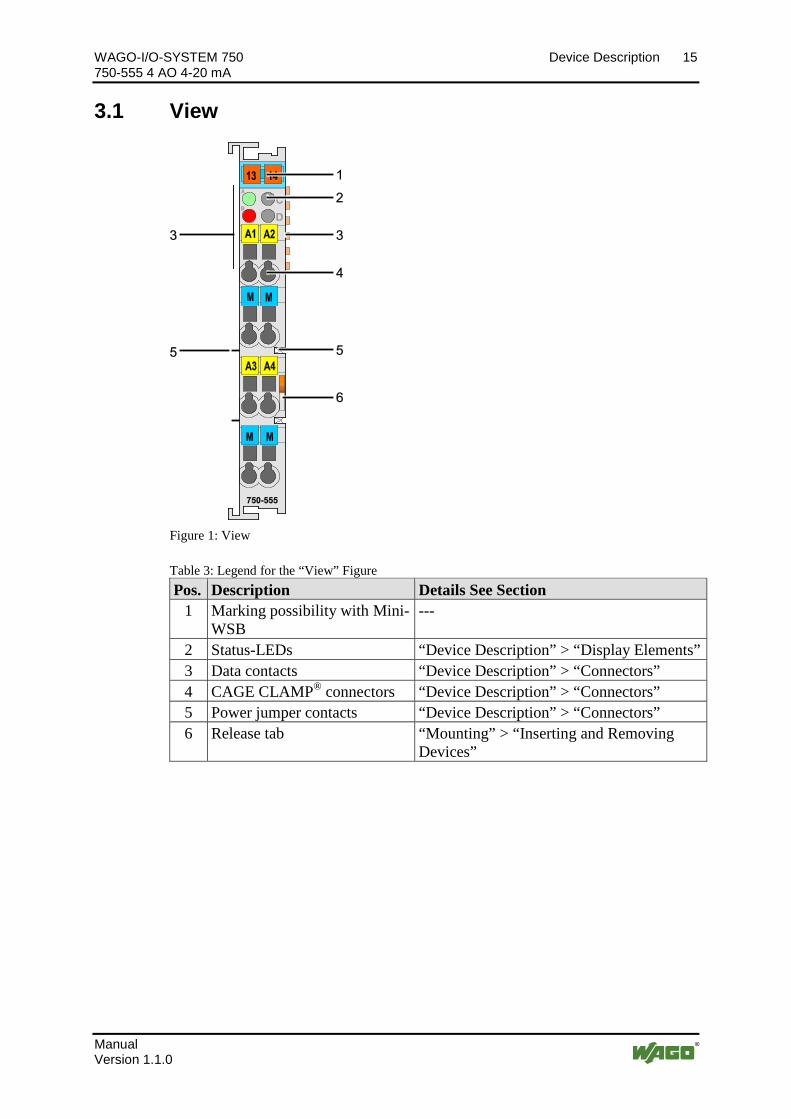
Figure 1: View Pos: 18.5 /Serie 750 (WAGO-I/O-SYSTEM)/Ger ätebeschrei bung/Ansicht/Ansicht C ageCl amp®_Legende mit LEDs @ 15\mod_1370867188922_21.docx @ 122225 @ @ 1
Table 3: Legend for the “View” Figure Pos. Description Details See Section
1 Marking possibility with Mini-WSB
---
2 Status-LEDs “Device Description” > “Display Elements” 3 Data contacts “Device Description” > “Connectors” 4 CAGE CLAMP® connectors “Device Description” > “Connectors” 5 Power jumper contacts “Device Description” > “Connectors” 6 Release tab “Mounting” > “Inserting and Removing
Devices”
Pos: 18.6 /Dokumentation allgemei n/Glieder ungselemente/---Seitenwechsel--- @ 3\mod_1221108045078_0.docx @ 21810 @ @ 1
16 Device Description WAGO-I/O-SYSTEM 750 750-555 4 AO 4-20 mA
Manual Version 1.1.0
Pos: 18.7 /All e Seri en ( Allgemei ne Module)/Ü berschriften für alle Serien/Gerätebeschreibung/Anschlüsse - Überschrift 2 @ 4\mod_1240984262656_21.docx @ 31961 @ 2 @ 1
3.2 Connectors Pos: 18.8 /Serie 750 (WAGO-I/O-SYSTEM)/Ger ätebeschrei bung/Anschl üsse/Datenkontakte/Kl emmenbus - Ü berschrift 3 @ 6\mod_1256294684083_21.docx @ 43660 @ 3 @ 1
3.2.1 Data Contacts/Internal Bus Pos: 18.9.1 /Serie 750 (WAGO-I/O-SYSTEM)/Gerätebeschrei bung/Anschlüsse/Datenkontakte - Feldbuskoppler/-controller , Abbildung und Beschrei bung @ 3\mod_1231771259187_21.docx @ 26002 @ @ 1
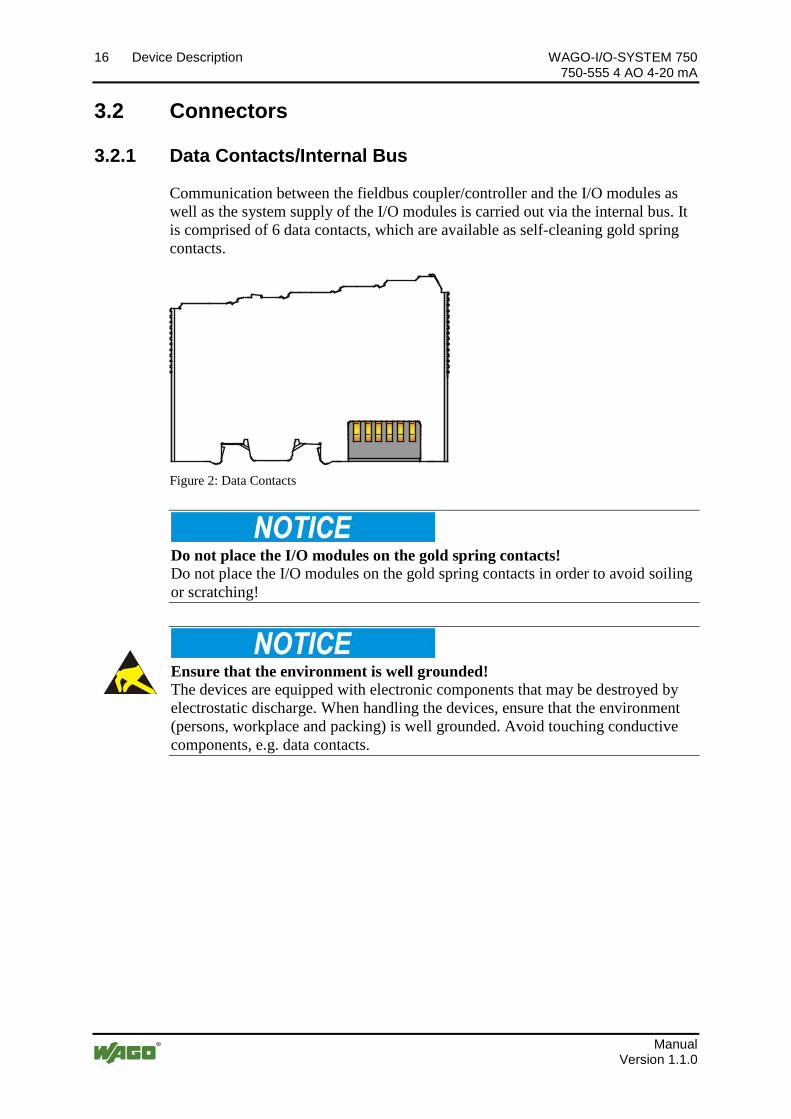
Communication between the fieldbus coupler/controller and the I/O modules as well as the system supply of the I/O modules is carried out via the internal bus. It is comprised of 6 data contacts, which are available as self-cleaning gold spring contacts.
Figure 2: Data Contacts Pos: 18.9.2 /Serie 750 (WAGO-I/O-SYSTEM)/Wichtige Erläuterungen/Sicherheits- und sonstige Hinweise/Achtung/Achtung: Buskl emmen nicht auf Gol dfeder kontakte leg en! @ 7\mod_1266318463636_21.docx @ 50695 @ @ 1
Do not place the I/O modules on the gold spring contacts! Do not place the I/O modules on the gold spring contacts in order to avoid soiling or scratching!
Pos: 18.9.3 /Serie 750 (WAGO-I/O-SYSTEM)/Wichtige Erläuterungen/Sicherheits- und sonstige Hinweise/Achtung/Achtung: ESD - Auf g ute Erdung der Umg ebung achten! @ 7\mod_1266318538667_21.docx @ 50708 @ @ 1
Ensure that the environment is well grounded! The devices are equipped with electronic components that may be destroyed by electrostatic discharge. When handling the devices, ensure that the environment (persons, workplace and packing) is well grounded. Avoid touching conductive components, e.g. data contacts.
Pos: 18.10 /D okumentati on allgemei n/Gli ederungsel emente/---Seitenwechsel--- @ 3\mod_1221108045078_0.docx @ 21810 @ @ 1
WAGO-I/O-SYSTEM 750 Device Description 17 750-555 4 AO 4-20 mA
Manual Version 1.1.0
Pos: 18.11 /Serie 750 ( WAGO-I/O-SYSTEM)/Gerätebeschr eibung/Anschlüsse/Leistungskontakte/Feldversorgung - Ü berschrif t 3 @ 6\mod_1256294692864_21.docx @ 43664 @ 3 @ 1
3.2.2 Power Jumper Contacts/Field Supply Pos: 18.12.1 /Serie 750 ( WAGO-I/O- SYSTEM)/Wichtig e Erl äuter ung en/Sicher hei ts- und sonstige Hi nweise/Vorsicht/Vorsicht: Verletzungsgefahr durch schar fkantige Messer kontakte! @ 6\mod_1256193279401_21.docx @ 43414 @ @ 1
Risk of injury due to sharp-edged blade contacts! The blade contacts are sharp-edged. Handle the I/O module carefully to prevent injury.
Pos: 18.12.2 /Serie 750 ( WAGO-I/O- SYSTEM)/Gerätebeschr eibung/Anschlüsse/Leistungskontakte 2 LK (M esser/Leistungskontakte 2 LK (Messer/Feder) - Einl eitung @ 15\mod_1371721641099_21.docx @ 123714 @ @ 1
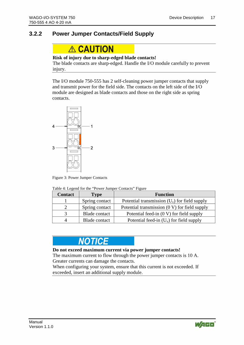
The I/O module 750-555 has 2 self-cleaning power jumper contacts that supply and transmit power for the field side. The contacts on the left side of the I/O module are designed as blade contacts and those on the right side as spring contacts.
Pos: 18.12.3 /Serie 750 ( WAGO-I/O- SYSTEM)/Gerätebeschr eibung/Anschlüsse/Leistungskontakte 2 LK (M esser/Leistungskontakte 2 LK (Messer/Feder) - Abbildung ( einfache Breite) @ 15\mod_1367500700037_21.docx @ 118396 @ @ 1
Figure 3: Power Jumper Contacts Pos: 18.12.4 /Serie 750 ( WAGO-I/O- SYSTEM)/Gerätebeschr eibung/Anschlüsse/Leistungskontakte 2 LK (M esser/Leistungskontakte 2 LK (Messer/Feder) - Leg ende @ 15\mod_1371721352500_21.docx @ 123710 @ @ 1
Table 4: Legend for the “Power Jumper Contacts” Figure Contact Type Function
1 Spring contact Potential transmission (Uv) for field supply 2 Spring contact Potential transmission (0 V) for field supply 3 Blade contact Potential feed-in (0 V) for field supply 4 Blade contact Potential feed-in (Uv) for field supply
Pos: 18.12.5 /Serie 750 ( WAGO-I/O- SYSTEM)/Wichtig e Erl äuter ung en/Sicher hei ts- und sonstige Hi nweise/Achtung/Achtung: Maxi maler Str om Leis tungskontakte 10 A @ 3\mod_1226499143500_21.docx @ 25029 @ @ 1
Do not exceed maximum current via power jumper contacts! The maximum current to flow through the power jumper contacts is 10 A. Greater currents can damage the contacts. When configuring your system, ensure that this current is not exceeded. If exceeded, insert an additional supply module.
Pos: 18.12.6 /Serie 750 ( WAGO-I/O- SYSTEM)/Wichtig e Erl äuter ung en/Sicher hei ts- und sonstige Hi nweise/Hinweis/Hi nweis : Potential einspeiseklemme für Erde einsetzen! (kein LK für Erde) @ 3\mod_1226499037468_21.docx @ 25023 @ @ 1
18 Device Description WAGO-I/O-SYSTEM 750 750-555 4 AO 4-20 mA
Manual Version 1.1.0
Use supply modules for ground (earth)! The I/O module has no power jumper contacts for receiving and transmitting the earth potential. Use a supply module when an earth potential is needed for the subsequent I/O modules.
Pos: 18.13 /D okumentati on allgemei n/Gli ederungsel emente/---Seitenwechsel--- @ 3\mod_1221108045078_0.docx @ 21810 @ @ 1
WAGO-I/O-SYSTEM 750 Device Description 19 750-555 4 AO 4-20 mA
Manual Version 1.1.0
Pos: 18.14 /Serie 750 ( WAGO-I/O-SYSTEM)/Gerätebeschr eibung/Anschlüsse/C AGE C LAMP-Anschlüsse - Ü berschrift 3 @ 6\mod_1256296337770_21.docx @ 43674 @ 3 @ 1
3.2.3 CAGE CLAMP® Connectors Pos: 18.15 /Serie 750 ( WAGO-I/O-SYSTEM)/Gerätebeschr eibung/Anschlüsse/Anal ogausgangsklemmen/Anschlüsse 750- 05xx 4 AO 2- Leiter @ 20\mod_1406282476661_21.docx @ 160093 @ @ 1
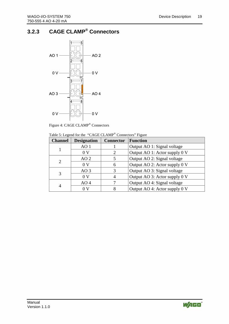
Figure 4: CAGE CLAMP® Connectors
Table 5: Legend for the “CAGE CLAMP® Connectors” Figure Channel Designation Connector Function
1 AO 1 1 Output AO 1: Signal voltage 0 V 2 Output AO 1: Actor supply 0 V
2 AO 2 5 Output AO 2: Signal voltage 0 V 6 Output AO 2: Actor supply 0 V
3 AO 3 3 Output AO 3: Signal voltage 0 V 4 Output AO 3: Actor supply 0 V
4 AO 4 7 Output AO 4: Signal voltage 0 V 8 Output AO 4: Actor supply 0 V
Pos: 18.16 /D okumentati on allgemei n/Gli ederungsel emente/---Seitenwechsel--- @ 3\mod_1221108045078_0.docx @ 21810 @ @ 1
20 Device Description WAGO-I/O-SYSTEM 750 750-555 4 AO 4-20 mA
Manual Version 1.1.0
Pos: 18.17 /Alle Serien (Allgemeine M odul e)/Überschriften für all e Seri en/Gerätebeschr eibung/Anzeigeel emente - Ü berschrift 2 @ 4\mod_1240984390875_21.docx @ 31964 @ 2 @ 1
3.3 Display Elements Pos: 18.18 /Serie 750 ( WAGO-I/O-SYSTEM)/Gerätebeschr eibung/Anzeig eel emente/Anal ogausgangskl emmen/Anzeig eel emente 750-0555 4AO (Agn, Br t) @ 20\mod_1406807365639_21.docx @ 160777 @ @ 1
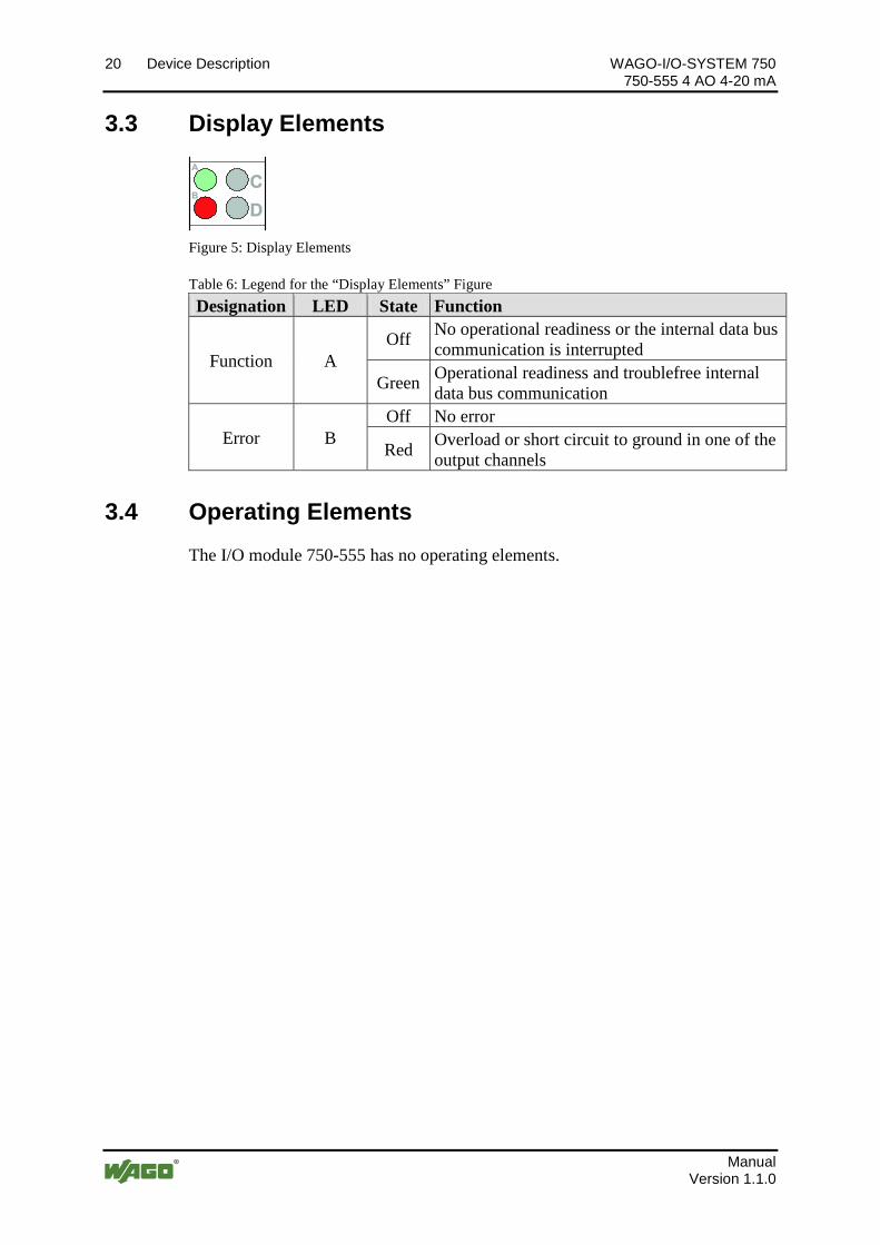
Figure 5: Display Elements
Table 6: Legend for the “Display Elements” Figure Designation LED State Function
Function A Off No operational readiness or the internal data bus
communication is interrupted
Green Operational readiness and troublefree internal data bus communication
Error B Off No error
Red Overload or short circuit to ground in one of the output channels
Pos: 18.19 /Alle Serien (Allgemeine M odul e)/Überschriften für all e Seri en/Gerätebeschr eibung/Bedi enelemente - Ü berschrift 2 @ 4\mod_1239191655456_21.docx @ 30439 @ 2 @ 1
3.4 Operating Elements Pos: 18.20 /Serie 750 ( WAGO-I/O-SYSTEM)/Gerätebeschr eibung/Bedi enel emente/Bedienelemente Buskl emme 750- xxxx nicht vorhanden @ 4\mod_1236322031125_21.docx @ 28063 @ @ 1
The I/O module 750-555 has no operating elements. Pos: 18.21 /D okumentati on allgemei n/Gli ederungsel emente/---Seitenwechsel--- @ 3\mod_1221108045078_0.docx @ 21810 @ @ 1
WAGO-I/O-SYSTEM 750 Device Description 21 750-555 4 AO 4-20 mA
Manual Version 1.1.0
Pos: 18.22 /Alle Serien (Allgemeine M odul e)/Überschriften für all e Seri en/Gerätebeschr eibung/Schematisches Schaltbild - Überschrift 2 @ 4\mod_1240984441312_21.docx @ 31967 @ 2 @ 1
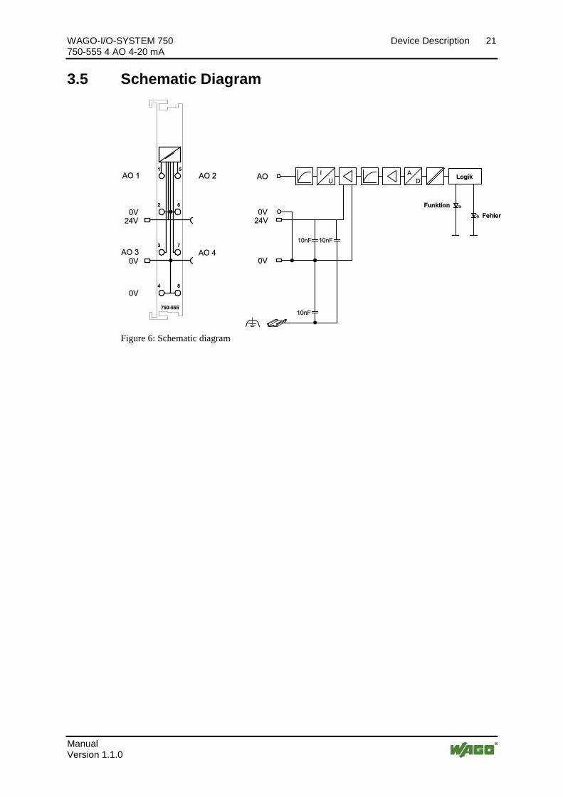
3.5 Schematic Diagram Pos: 18.23 /Serie 750 ( WAGO-I/O-SYSTEM)/Gerätebeschr eibung/Schematische Schaltbilder/Analog ausg angskl emmen/Schematisches Schaltbild 750- 0555 @ 20\mod_1406289693384_21.docx @ 160285 @ @ 1
Figure 6: Schematic diagram Pos: 18.24 /D okumentati on allgemei n/Gli ederungsel emente/---Seitenwechsel--- @ 3\mod_1221108045078_0.docx @ 21810 @ @ 1
22 Device Description WAGO-I/O-SYSTEM 750 750-555 4 AO 4-20 mA
Manual Version 1.1.0
Pos: 18.25 /Alle Serien (Allgemeine M odul e)/Überschriften für all e Seri en/Gerätebeschr eibung/Technische D aten - Ü berschrift 2 @ 3\mod_1232967587687_21.docx @ 26924 @ 2 @ 1
3.6 Technical Data Pos: 18.26 /Serie 750 ( WAGO-I/O-SYSTEM)/Gerätebeschr eibung/Technische D aten/Analog ausg angskl emmen/Technische D aten 750-0555 @ 20\mod_1406645074175_21.docx @ 160541 @ 3333 @ 1
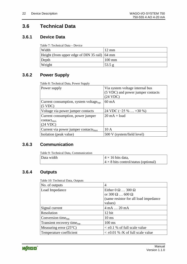
3.6.1 Device Data
Table 7: Technical Data – Device Width 12 mm Height (from upper edge of DIN 35 rail) 64 mm Depth 100 mm Weight 53.5 g
3.6.2 Power Supply
Table 8: Technical Data, Power Supply Power supply Via system voltage internal bus
(5 VDC) and power jumper contacts (24 VDC)
Current consumption, system voltagetyp. (5 VDC)
60 mA
Voltage via power jumper contacts 24 VDC (−25 % … +30 %) Current consumption, power jumper contactmax. (24 VDC)
20 mA + load
Current via power jumper contactsmax 10 A Isolation (peak value) 500 V (system/field level)
3.6.3 Communication
Table 9: Technical Data, Communication Data width 4 × 16 bits data,
4 × 8 bits control/status (optional)
3.6.4 Outputs
Table 10: Technical Data, Outputs No. of outputs 4 Load Impedance Either 0 Ω … 300 Ω
or 300 Ω … 600 Ω (same resistor for all load impedance values)
Signal current 4 mA … 20 mA Resolution 12 bit Conversion timetyp. 10 ms Transient recovery timetyp. 100 ms Measuring error (25°C) < ±0.1 % of full scale value Temperature coefficient < ±0.01 % /K of full scale value
Pos: 18.27 /D okumentati on allgemei n/Gli ederungsel emente/---Seitenwechsel--- @ 3\mod_1221108045078_0.docx @ 21810 @ @ 1
WAGO-I/O-SYSTEM 750 Device Description 23 750-555 4 AO 4-20 mA
Manual Version 1.1.0
Pos: 18.28.1 /Alle Serien (Allgemeine M odul e)/Überschriften für all e Serien/Gerätebeschr eibung/Anschl uss techni k - Ü berschrift 3 @ 17\mod_1380123271324_21.docx @ 132788 @ 3 @ 1
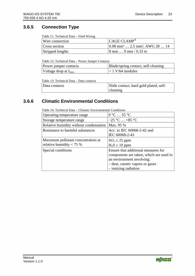
3.6.5 Connection Type Pos: 18.28.2 /Serie 750 ( WAGO-I/O- SYSTEM)/Gerätebeschr eibung/Technische D aten/Technische D aten Verdrahtungsebene CC - 0,08 bis 2,5mm2 @ 17\mod_1380121238809_21.docx @ 132780 @ @ 1
Table 11: Technical Data – Field Wiring Wire connection CAGE CLAMP® Cross section 0.08 mm² … 2.5 mm², AWG 28 … 14 Stripped lengths 8 mm … 9 mm / 0.33 in
Pos: 18.28.3 /Serie 750 ( WAGO-I/O- SYSTEM)/Gerätebeschr eibung/Technische D aten/Anschl usstechni k/Technische Daten Leis tungskontakte (Messer/Feder) @ 17\mod_1380123464149_21.docx @ 132791 @ @ 1
Table 12: Technical Data – Power Jumper Contacts Power jumper contacts Blade/spring contact, self-cleaning Voltage drop at Imax. < 1 V/64 modules
Pos: 18.28.4 /Serie 750 ( WAGO-I/O- SYSTEM)/Gerätebeschr eibung/Technische D aten/Anschl usstechni k/Technische Daten D atenkontakte @ 17\mod_1380123495844_21.docx @ 132794 @ @ 1
Table 13: Technical Data – Data contacts Data contacts Slide contact, hard gold plated, self-
cleaning
Pos: 18.29 /Serie 750 ( WAGO-I/O-SYSTEM)/Gerätebeschr eibung/Technische D aten/Klimatische U mweltbedingungen/Technische D aten Kli matische U mweltbedi ngungen o. er w. Tempbereich; 0. ..55°C/-25...+ 85°C @ 5\mod_1247657968368_21.docx @ 37603 @ 3 @ 1
3.6.6 Climatic Environmental Conditions
Table 14: Technical Data – Climatic Environmental Conditions Operating temperature range 0 °C … 55 °C Storage temperature range −25 °C … +85 °C Relative humidity without condensation Max. 95 % Resistance to harmful substances Acc. to IEC 60068-2-42 and
IEC 60068-2-43 Maximum pollutant concentration at relative humidity < 75 %
SO2 ≤ 25 ppm H2S ≤ 10 ppm
Special conditions Ensure that additional measures for components are taken, which are used in an environment involving: – dust, caustic vapors or gases – ionizing radiation
Pos: 18.30 /D okumentati on allgemei n/Gli ederungsel emente/---Seitenwechsel--- @ 3\mod_1221108045078_0.docx @ 21810 @ @ 1
24 Device Description WAGO-I/O-SYSTEM 750 750-555 4 AO 4-20 mA
Manual Version 1.1.0
Pos: 18.31 /Alle Serien (Allgemeine M odul e)/Überschriften für all e Seri en/Gerätebeschr eibung/Zulassungen - Ü berschrif t 2 @ 3\mod_1224055364109_21.docx @ 24030 @ 2 @ 1
3.7 Approvals Pos: 18.32 /Serie 750 ( WAGO-I/O-SYSTEM)/Gerätebeschr eibung/Zul assung en/Infor mati on: Wei ter e Informati onen zu Zulassungen 750- xxxx @ 3\mod_1227190967156_21.docx @ 25221 @ @ 1
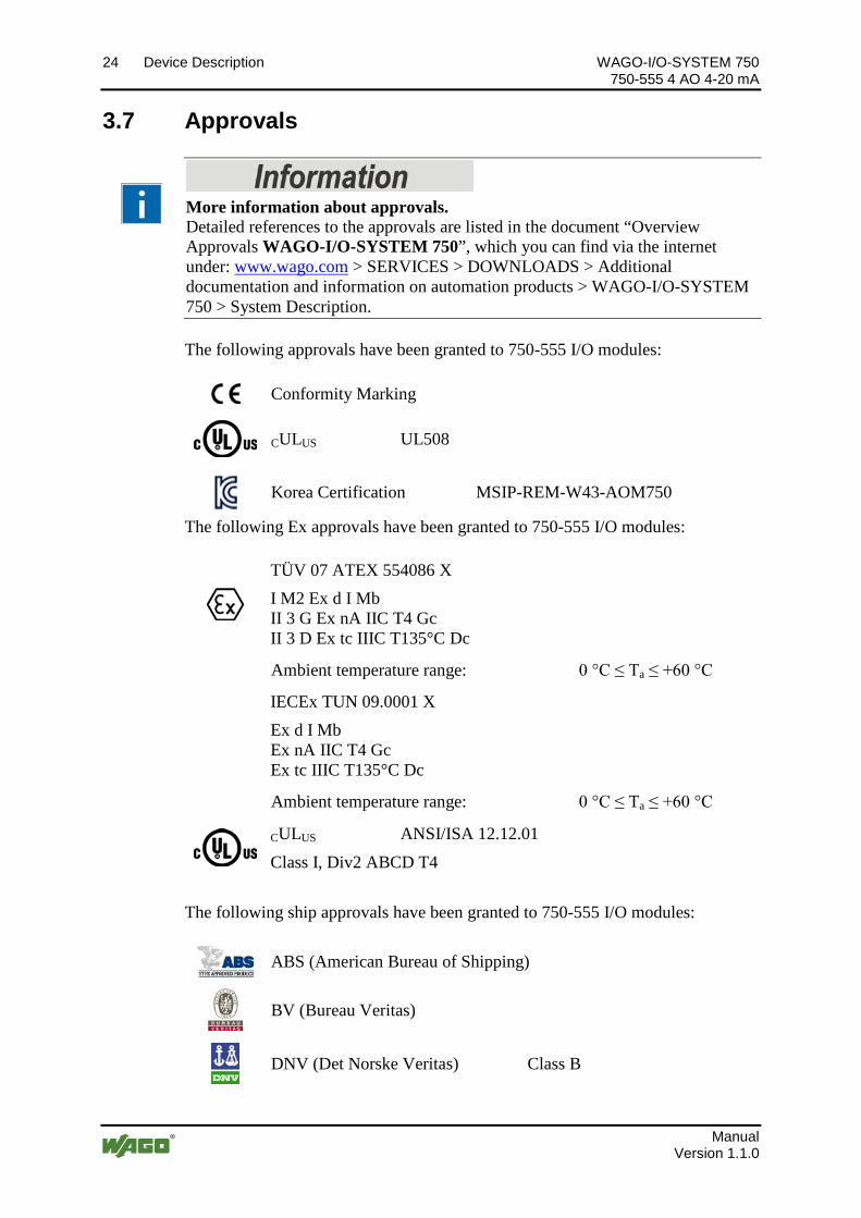
More information about approvals. Detailed references to the approvals are listed in the document “Overview Approvals WAGO-I/O-SYSTEM 750”, which you can find via the internet under: www.wago.com > SERVICES > DOWNLOADS > Additional documentation and information on automation products > WAGO-I/O-SYSTEM 750 > System Description.
Pos: 18.33 /Serie 750 ( WAGO-I/O-SYSTEM)/Gerätebeschr eibung/Zul assung en/Allgemein/Zul assung en Busklemme 750- xxxx Allgemei n, ohne Vari antenangabe - Einlei tung @ 4\mod_1237460656921_21.docx @ 28643 @ @ 1
The following approvals have been granted to 750-555 I/O modules: Pos: 18.34.1 /Alle Serien (Allgemeine D okumente) (Allgemeine M odul e)/Zulassungen/Standar dzul assungen/CE (Konfor mitätskennzeichnung) @ 3\mod_1224494777421_21.docx @ 24276 @ @ 1
Conformity Marking Pos: 18.34.2 /Alle Serien (Allgemeine D okumente) (Allgemeine M odul e)/Zulassungen/Standar dzul assungen/cU Lus (UL508) @ 3\mod_1224055013140_0.docx @ 24020 @ @ 1
CULUS UL508 Pos: 18.34.3 /D okumentati on allgemein/Gli ederungsel emente/------Leerzeil e------ @ 3\mod_1224662755687_0.docx @ 24460 @ @ 1
Pos : 18.35 /Alle Serien (Allgemeine M odul e)/Zulassungen/KC - Korea C ertificate - AO @ 20\mod_1406533092951_21.docx @ 160372 @ @ 1
Korea Certification MSIP-REM-W43-AOM750 Pos: 18.36 /Serie 750 ( WAGO-I/O-SYSTEM)/Gerätebeschr eibung/Zul assung en/Ex/Zul assung en Buskl emme 750- xxxx Ex, ohne Variantenang abe - Einl eitung @ 4\mod_1237191218000_21.docx @ 28423 @ @ 1
The following Ex approvals have been granted to 750-555 I/O modules: Pos: 18.37.1 /Alle Serien (Allgemeine M odul e)/Zulassungen/Ex-Zul assungen/TÜ V ATEX/TÜV 07 ATEX 554086 X: I M 2 Ex d I Mb II 3 G Ex nA IIC T4 Gc II 3 D Ex tc II IC T135°C Dc @ 14\mod_1361949753233_0.docx @ 113015 @ @ 1
TÜV 07 ATEX 554086 X I M2 Ex d I Mb II 3 G Ex nA IIC T4 Gc II 3 D Ex tc IIIC T135°C Dc
Pos: 18.37.2 /Alle Serien (Allgemeine M odul e)/Zulassungen/Ex-Zul assungen/Ergänzung Zulässiger U mgebungstemperatur ber eich 0 °C <= Ta <= + 60 °C @ 9\mod_1295605895541_21.docx @ 68610 @ @ 1
Ambient temperature range: 0 °C ≤ Ta ≤ +60 °C Pos: 18.37.3 /Alle Serien (Allgemeine M odul e)/Zulassungen/Ex-Zul assungen/IEC Ex (TÜ V N ord)/ IEC Ex TUN 09.0001 X: Ex d I Mb Ex nA IIC T4 Gc Ex tc I IIC T135°C @ 14\mod_1361950034299_0.docx @ 113019 @ @ 1
IECEx TUN 09.0001 X Ex d I Mb Ex nA IIC T4 Gc Ex tc IIIC T135°C Dc
Pos: 18.37.4 /Alle Serien (Allgemeine M odul e)/Zulassungen/Ex-Zul assungen/Ergänzung Zulässiger U mgebungstemperatur ber eich 0 °C <= Ta <= + 60 °C @ 9\mod_1295605895541_21.docx @ 68610 @ @ 1
Ambient temperature range: 0 °C ≤ Ta ≤ +60 °C Pos: 18.37.5 /Alle Serien (Allgemeine M odul e)/Zulassungen/Ex-Zul assungen/cULus/cU Lus ( ANSI/ISA 12.12.01) Cl ass I, Di v2 ABCD T4 @ 3\mod_1224054791812_0.docx @ 24014 @ @ 1
CULUS ANSI/ISA 12.12.01 Class I, Div2 ABCD T4
Pos: 18.37.6 /D okumentati on allgemein/Gli ederungsel emente/------Leerzeil e------ @ 3\mod_1224662755687_0.docx @ 24460 @ @ 1
Pos: 18.38 /Serie 750 ( WAGO-I/O-SYSTEM)/Gerätebeschr eibung/Zul assung en/Schiff /Zul assungen Buskl emme 750- xxxx Schiff, ohne Variantenangabe - Ei nleitung @ 4\mod_1237190918453_21.docx @ 28420 @ @ 1
The following ship approvals have been granted to 750-555 I/O modules: Pos: 18.39.1 /Alle Serien (Allgemeine D okumente) (Allgemeine M odul e)/Zulassungen/Schif fszulassungen/ABS (American Bur eau of Shippi ng) @ 3\mod_1224055151062_0.docx @ 24023 @ @ 1
ABS (American Bureau of Shipping) Pos: 18.39.2 /Alle Serien (Allgemeine D okumente) (Allgemeine M odul e)/Zulassungen/Schif fszulassungen/BV ( Bur eau Veritas) @ 3\mod_1224492116171_0.docx @ 24220 @ @ 1
BV (Bureau Veritas)
Pos: 18.39.3 /Alle Serien (Allgemeine D okumente) (Allgemeine M odul e)/Zulassungen/Schif fszulassungen/DN V (Det N orske Veritas) Class B @ 3\mod_1224492540562_0.docx @ 24224 @ @ 1
DNV (Det Norske Veritas) Class B
Pos: 18.39.4 /Alle Serien (Allgemeine D okumente) (Allgemeine M odul e)/Zulassungen/Schif fszulassungen/GL ( Ger manischer Ll oyd) C at. A, B, C, D (EMC 1) @ 3\mod_1224492724484_0.docx @ 24228 @ @ 1
WAGO-I/O-SYSTEM 750 Device Description 25 750-555 4 AO 4-20 mA
Manual Version 1.1.0
GL (Germanischer Lloyd) Cat. A, B, C, D (EMC 1)
Pos: 18.39.5 /Alle Serien (Allgemeine D okumente) (Allgemeine M odul e)/Zulassungen/Schif fszulassungen/KR (Korean Register of Shipping) @ 3\mod_1224492806109_0.docx @ 24232 @ @ 1
KR (Korean Register of Shipping) Pos: 18.39.6 /Alle Serien (Allgemeine D okumente) (Allgemeine M odul e)/Zulassungen/Schif fszulassungen/LR (Ll oyd’s R egister) Env. 1, 2, 3, 4 @ 3\mod_1224492890453_0.docx @ 24236 @ @ 1
LR (Lloyd’s Register) Env. 1, 2, 3, 4 Pos: 18.39.7 /Alle Serien (Allgemeine D okumente) (Allgemeine M odul e)/Zulassungen/Schif fszulassungen/N KK (Ni ppon Kaiji Kyokai) @ 3\mod_1224493002656_0.docx @ 24240 @ @ 1
NKK (Nippon Kaiji Kyokai)
Pos: 18.39.8 /Alle Serien (Allgemeine D okumente) (Allgemeine M odul e)/Zulassungen/Schif fszulassungen/PRS ( Polski Rej estr Statków) @ 3\mod_1224497273250_0.docx @ 24295 @ @ 1
PRS (Polski Rejestr Statków)
Pos: 18.39.9 /Alle Serien (Allgemeine D okumente) (Allgemeine M odul e)/Zulassungen/Schif fszulassungen/RIN A (R egistro Italiano Navale) @ 3\mod_1224493078359_0.docx @ 24244 @ @ 1
RINA (Registro Italiano Navale)
Pos: 18.39.10 /D okumentation allgemein/Gliederungselemente/------Leerzeile------ @ 3\mod_1224662755687_0.docx @ 24460 @ @ 1
Pos: 18.40 /D okumentati on allgemei n/Gli ederungsel emente/---Seitenwechsel--- @ 3\mod_1221108045078_0.docx @ 21810 @ @ 1
26 Device Description WAGO-I/O-SYSTEM 750 750-555 4 AO 4-20 mA
Manual Version 1.1.0
Pos: 18.41 /Alle Serien (Allgemeine M odul e)/Überschriften für all e Seri en/Gerätebeschr eibung/N or men und Ri chtli nien - Ü berschrif t 2 @ 4\mod_1242804031875_21.docx @ 33646 @ 2 @ 1
3.8 Standards and Guidelines Pos: 18.42 /Serie 750 ( WAGO-I/O-SYSTEM)/Gerätebeschr eibung/Nor men und Richtlinien/EMV-N or men Busklemme 750- xxxx, ohne Variantenangabe - Ei nleitung @ 4\mod_1242803944015_21.docx @ 33642 @ @ 1
750-555 I/O modules meet the following requirements on emission and immunity of interference:
Pos: 18.43 /Alle Serien (Allgemeine M odul e)/Nor men und Richtlini en/EM V-Nor men - Standard/EM V C E-Störaussendung EN 61000-6-4: 2007 @ 4\mod_1242798273984_21.docx @ 33602 @ @ 1
EMC CE-Emission of interference acc. to EN 61000-6-4: 2007 Pos: 18.44 /Alle Serien (Allgemeine M odul e)/Nor men und Richtlini en/EM V-Nor men - Standard/EM V C E-Störfestig keit EN 61000-6- 2: 2005 @ 4\mod_1242797655625_21.docx @ 33591 @ @ 1
EMC CE-Immunity to interference acc. to EN 61000-6-2: 2005 Pos: 18.45 /Alle Serien (Allgemeine M odul e)/Nor men und Richtlini en/EM V-Nor men - Schif fbau/EM V Schi ffbau-Stör aussendung Germanischer Lloyd (2003) @ 4\mod_1242798400546_21.docx @ 33606 @ @ 1
EMC marine applications-Emission of interference acc. to Germanischer Lloyd (2003)
Pos: 18.46 /Alle Serien (Allgemeine M odul e)/Nor men und Richtlini en/EM V-Nor men - Schif fbau/EM V Schi ffbau-Störfestig keit Ger manischer Ll oyd (2003) @ 4\mod_1242798409640_21.docx @ 33610 @ @ 1
EMC marine applications-Immunity to interference acc. to Germanischer Lloyd (2003)
Pos: 18.47 /D okumentati on allgemei n/Gli ederungsel emente/---Seitenwechsel--- @ 3\mod_1221108045078_0.docx @ 21810 @ @ 1
WAGO-I/O-SYSTEM 750 Process Image 27 750-555 4 AO 4-20 mA
Manual Version 1.1.0
Pos: 19 /All e Seri en (Allgemei ne Module)/Ü berschrif ten für alle Serien/Pr ozessabbild - Überschrift 1 @ 4\mod_1240983067828_21.docx @ 31942 @ 1 @ 1
4 Process Image Pos: 20 /Serie 750 ( WAGO-I/O-SYSTEM)/Prozessabbild Kl emmenbus /Hinweis: Prozessabbildmapping abhängig von FBK/PFC, ohne Status-/C ontr olbyte @ 6\mod_1256126797251_21.docx @ 43340 @ @ 1
Mapping of process data in the process image of fieldbus systems The representation of the process data of some I/O modules or their variations in the process image depends on the fieldbus coupler/controller used. Please take this information from the section "Fieldbus Specific Design of the Process Data" included in the description concerning the process image of the corresponding coupler/controller.
Pos: 21 /Serie 750 ( WAGO-I/O-SYSTEM)/Prozessabbild Kl emmenbus /Analogausgangsklemmen/Pr ozessabbild 750- 0555 @ 20\mod_1406641931640_21.docx @ 160538 @ @ 1
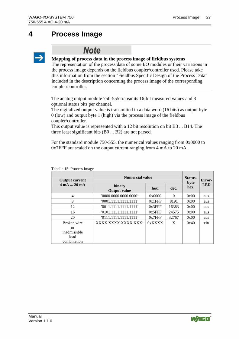
The analog output module 750-555 transmits 16-bit measured values and 8 optional status bits per channel. The digitalized output value is transmitted in a data word (16 bits) as output byte 0 (low) and output byte 1 (high) via the process image of the fieldbus coupler/controller. This output value is represented with a 12 bit resolution on bit B3 ... B14. The three least significant bits (B0 ... B2) are not parsed.
For the standard module 750-555, the numerical values ranging from 0x0000 to 0x7FFF are scaled on the output current ranging from 4 mA to 20 mA.
Tabelle 15: Process Image
Output current 4 mA ... 20 mA
Numercial value Status- byte hex.
Error-LED binary
Output value hex. dec.
4 ’0000.0000.0000.0000’ 0x0000 0 0x00 aus 8 ’0001.1111.1111.1111’ 0x1FFF 8191 0x00 aus 12 ’0011.1111.1111.1111’ 0x3FFF 16383 0x00 aus 16 ’0101.1111.1111.1111’ 0x5FFF 24575 0x00 aus 20 ’0111.1111.1111.1111’ 0x7FFF 32767 0x00 aus
Broken wire or
inadmissible load
combination
XXXX.XXXX.XXXX.XXX’ 0xXXXX X 0x40 ein
Pos: 22 /D okumentation allgemei n/Glieder ungselemente/---Seitenwechsel--- @ 3\mod_1221108045078_0.docx @ 21810 @ @ 1
28 Mounting WAGO-I/O-SYSTEM 750 750-555 4 AO 4-20 mA
Manual Version 1.1.0
Pos: 23 /All e Seri en (Allgemei ne Module)/Ü berschrif ten für alle Serien/Monti eren - D emontieren/M ontier en - Überschrift 1 @ 3\mod_1225446744750_21.docx @ 24900 @ 1 @ 1
5 Mounting Pos: 24.1 /Serie 750 (WAGO-I/O-SYSTEM)/M ontieren/D emontieren/M ontagerei henfolge @ 3\mod_1231770210031_21.docx @ 25992 @ 2 @ 1
5.1 Mounting Sequence Fieldbus couplers/controllers and I/O modules of the WAGO-I/O-SYSTEM 750 are snapped directly on a carrier rail in accordance with the European standard EN 50022 (DIN 35).
The reliable positioning and connection is made using a tongue and groove system. Due to the automatic locking, the individual devices are securely seated on the rail after installation.
Starting with the fieldbus coupler/controller, the I/O modules are mounted adjacent to each other according to the project design. Errors in the design of the node in terms of the potential groups (connection via the power contacts) are recognized, as the I/O modules with power contacts (blade contacts) cannot be linked to I/O modules with fewer power contacts.
Pos: 24.2 /Serie 750 (WAGO-I/O-SYSTEM)/Wichtige Erläuterungen/Sicherheits- und sonstig e Hinweise/Vorsicht/Vorsicht: Verl etzungsgefahr durch scharfkantige M esser kontakte! @ 6\mod_1256193279401_21.docx @ 43414 @ @ 1
Risk of injury due to sharp-edged blade contacts! The blade contacts are sharp-edged. Handle the I/O module carefully to prevent injury.
Pos: 24.3 /Serie 750 (WAGO-I/O-SYSTEM)/Wichtige Erläuterungen/Sicherheits- und sonstig e Hinweise/Achtung/Achtung: Buskl emmen nur in vorgesehener R eihenfolg e stecken! @ 6\mod_1256194177073_21.docx @ 43429 @ @ 1
Insert I/O modules only from the proper direction! All I/O modules feature grooves for power jumper contacts on the right side. For some I/O modules, the grooves are closed on the top. Therefore, I/O modules featuring a power jumper contact on the left side cannot be snapped from the top. This mechanical coding helps to avoid configuration errors, which may destroy the I/O modules. Therefore, insert I/O modules only from the right and from the top.
Pos: 24.4 /Serie 750 (WAGO-I/O-SYSTEM)/Wichtige Erläuterungen/Sicherheits- und sonstig e Hinweise/Hinweis/Hi nweis: Busabschluss nicht vergessen! @ 6\mod_1256194225557_21.docx @ 43432 @ @ 1
Don't forget the bus end module! Always plug a bus end module 750-600 onto the end of the fieldbus node! You must always use a bus end module at all fieldbus nodes with WAGO-I/O- SYSTEM 750 fieldbus couplers/controllers to guarantee proper data transfer.
Pos: 24.5 /Dokumentation allgemei n/Glieder ungselemente/---Seitenwechsel--- @ 3\mod_1221108045078_0.docx @ 21810 @ @ 1
WAGO-I/O-SYSTEM 750 Mounting 29 750-555 4 AO 4-20 mA
Manual Version 1.1.0
Pos: 24.6 /Serie 750 (WAGO-I/O-SYSTEM)/M ontieren/D emontieren/Geräte einfüg en und entfer nen - Ü berschrif t 2 @ 3\mod_1231768483250_21.docx @ 25950 @ 2 @ 1
5.2 Inserting and Removing Devices Pos: 24.7 /All e Seri en ( Allgemei ne Module)/Wichtige Erläuterungen/Sicherheits- und sons tige Hi nweise/Achtung/Achtung: Arbeiten an Ger äten nur spannungsfr ei durchführ en! @ 6\mod_1256193963573_21.docx @ 43426 @ @ 1
Perform work on devices only if they are de-energized! Working on energized devices can damage them. Therefore, turn off the power supply before working on the devices.
Pos: 24.8 /Serie 750 (WAGO-I/O-SYSTEM)/M ontieren/D emontieren/Busklemme einfüg en @ 3\mod_1231769726703_21.docx @ 25989 @ 3 @ 1
5.2.1 Inserting the I/O Module
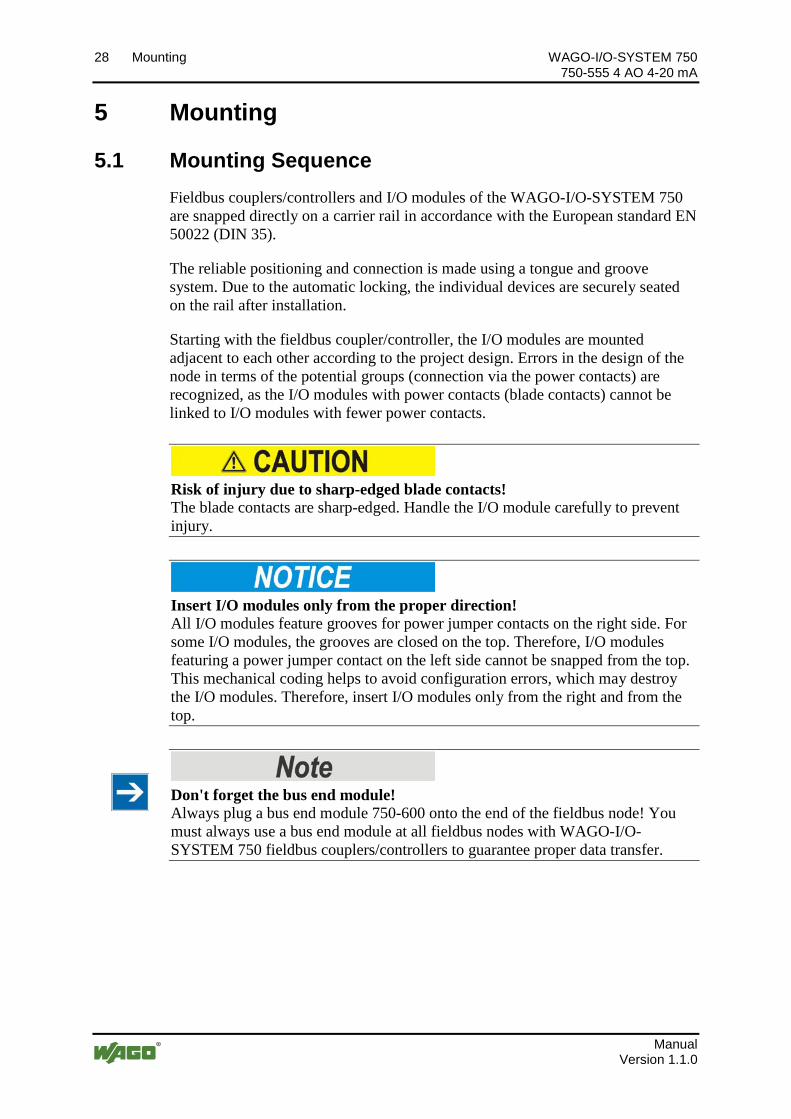
1. Position the I/O module so that the tongue and groove joints to the fieldbus coupler/controller or to the previous or possibly subsequent I/O module are engaged.
Figure 7: Insert I/O module (sample)
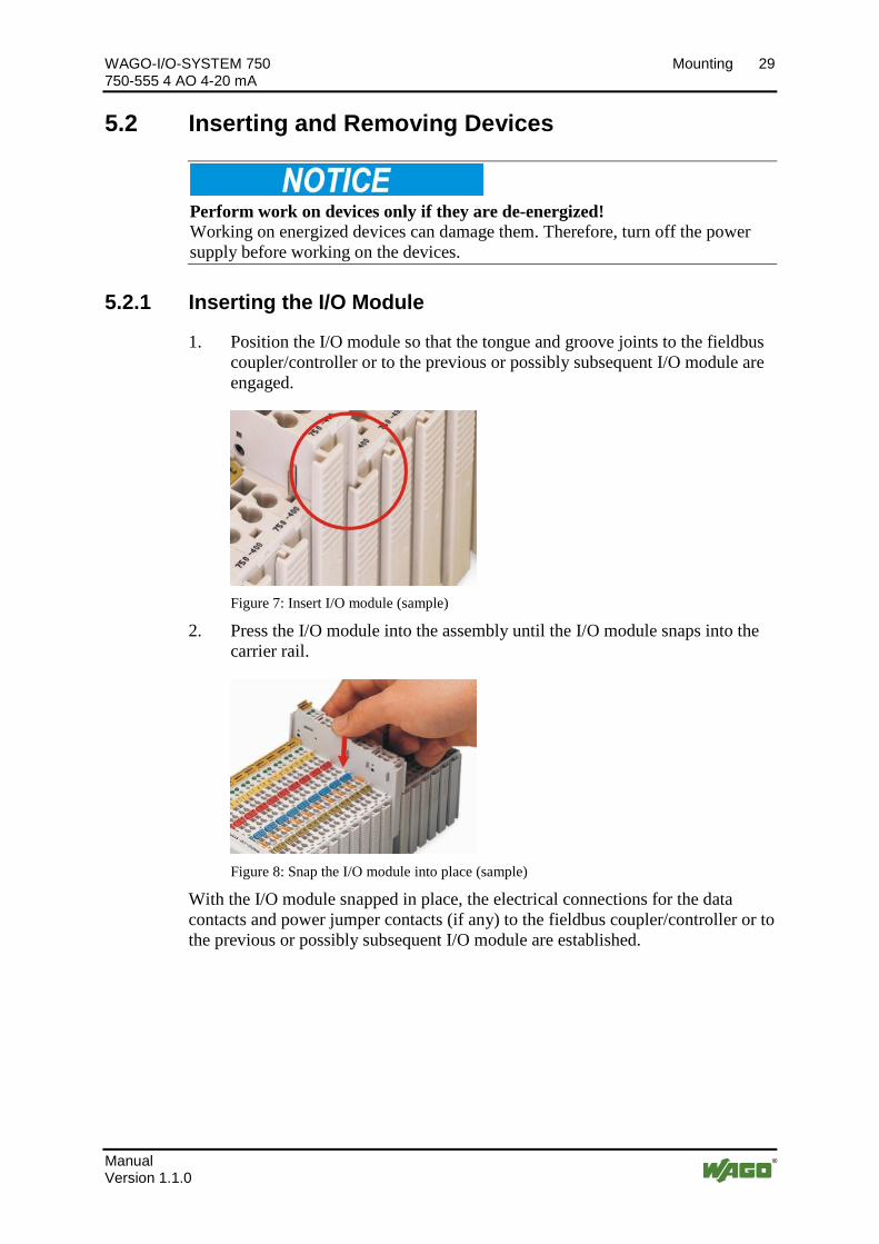
2. Press the I/O module into the assembly until the I/O module snaps into the carrier rail.
Figure 8: Snap the I/O module into place (sample)
With the I/O module snapped in place, the electrical connections for the data contacts and power jumper contacts (if any) to the fieldbus coupler/controller or to the previous or possibly subsequent I/O module are established.
Pos: 24.9 /Dokumentation allgemei n/Glieder ungselemente/---Seitenwechsel--- @ 3\mod_1221108045078_0.docx @ 21810 @ @ 1
30 Mounting WAGO-I/O-SYSTEM 750 750-555 4 AO 4-20 mA
Manual Version 1.1.0
Pos: 24.10 /Serie 750 ( WAGO-I/O-SYSTEM)/Monti eren/D emonti eren/Buskl emme entfer nen @ 4\mod_1239169375203_21.docx @ 30334 @ 3 @ 1
5.2.2 Removing the I/O Module
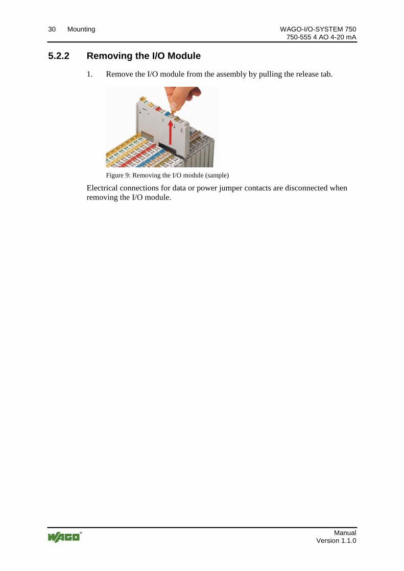
1. Remove the I/O module from the assembly by pulling the release tab.
Figure 9: Removing the I/O module (sample)
Electrical connections for data or power jumper contacts are disconnected when removing the I/O module.
Pos: 25 /D okumentation allgemei n/Glieder ungselemente/---Seitenwechsel--- @ 3\mod_1221108045078_0.docx @ 21810 @ @ 1
WAGO-I/O-SYSTEM 750 Connect Devices 31 750-555 4 AO 4-20 mA
Manual Version 1.1.0
Pos: 26 /All e Seri en (Allgemei ne Module)/Ü berschrif ten für alle Serien/Anschließen/Ger äte anschließen - Ü berschrift 1 @ 3\mod_1234172889468_21.docx @ 27460 @ 1 @ 1
6 Connect Devices Pos: 27 /Serie 750 ( WAGO-I/O-SYSTEM)/Anschli eßen/Leiter an C AGE C LAM P anschli eßen ( allgemei n) - Überschrift 2 und Text @ 3\mod_1225448660171_21.docx @ 24928 @ 2 @ 1
6.1 Connecting a Conductor to the CAGE CLAMP® The WAGO CAGE CLAMP® connection is appropriate for solid, stranded and finely stranded conductors.
Only connect one conductor to each CAGE CLAMP®! Only one conductor may be connected to each CAGE CLAMP®. Do not connect more than one conductor at one single connection!
If more than one conductor must be routed to one connection, these must be connected in an up-circuit wiring assembly, for example using WAGO feed-through terminals.
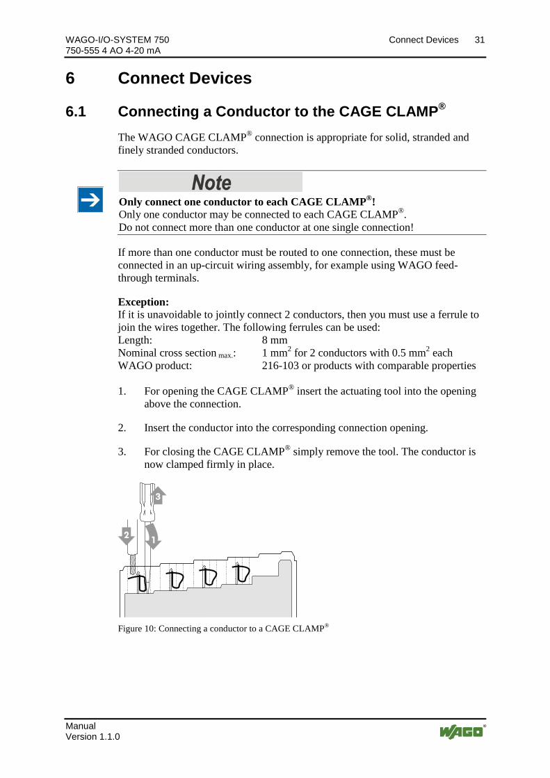
Exception: If it is unavoidable to jointly connect 2 conductors, then you must use a ferrule to join the wires together. The following ferrules can be used: Length: 8 mm Nominal cross section max.: 1 mm2 for 2 conductors with 0.5 mm2 each WAGO product: 216-103 or products with comparable properties 1. For opening the CAGE CLAMP® insert the actuating tool into the opening
above the connection.
2. Insert the conductor into the corresponding connection opening.
3. For closing the CAGE CLAMP® simply remove the tool. The conductor is now clamped firmly in place.
Figure 10: Connecting a conductor to a CAGE CLAMP® Pos: 28 /D okumentation allgemei n/Glieder ungselemente/---Seitenwechsel--- @ 3\mod_1221108045078_0.docx @ 21810 @ @ 1
32 Connect Devices WAGO-I/O-SYSTEM 750 750-555 4 AO 4-20 mA
Manual Version 1.1.0
Pos: 29 /All e Seri en (Allgemei ne Module)/Ü berschrif ten für alle Serien/Anschließen/Anschl ussbeispiel e - Ü berschrif t 2 @ 4\mod_1240996036328_21.docx @ 32010 @ 2 @ 1
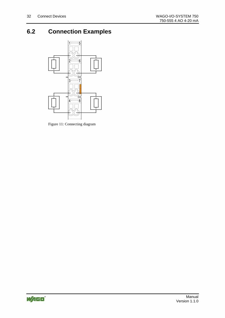
6.2 Connection Examples Pos: 30 /Serie 750 ( WAGO-I/O-SYSTEM)/Anschli eßen/Anschl ussbeispi ele/Anal ogausgangsklemmen/Anschlussbeispiel e 750-0555 @ 20\mod_1406711317754_21.docx @ 160608 @ @ 1
Figure 11: Connecting diagram Pos : 31 /D okumentation allgemei n/Glieder ungselemente/---Seitenwechsel--- @ 3\mod_1221108045078_0.docx @ 21810 @ @ 1
WAGO-I/O-SYSTEM 750 Use in Hazardous Environments 33 750-555 4 AO 4-20 mA
Manual Version 1.1.0
Pos: 32.1 /All e Seri en ( Allgemei ne Module)/Einsatz in Ex- Ber eichen/Einsatz in explosionsgefährdeten Bereichen - Überschrift 1 @ 3\mod_1224075191281_21.docx @ 24084 @ 1 @ 1
7 Use in Hazardous Environments Pos: 32.2 /Serie 750 (WAGO-I/O-SYSTEM)/Einsatz in Ex- Ber eichen/Ei nsatzber eich Serie 750 @ 3\mod_1234272230203_21.docx @ 27500 @ @ 1
The WAGO-I/O-SYSTEM 750 (electrical equipment) is designed for use in Zone 2 hazardous areas.
The following sections include both the general identification of components (devices) and the installation regulations to be observed. The individual subsections of the “Installation Regulations” section must be taken into account if the I/O module has the required approval or is subject to the range of application of the ATEX directive.
Pos: 32.3 /Dokumentation allgemei n/Glieder ungselemente/---Seitenwechsel--- @ 3\mod_1221108045078_0.docx @ 21810 @ @ 1
34 Use in Hazardous Environments WAGO-I/O-SYSTEM 750 750-555 4 AO 4-20 mA
Manual Version 1.1.0
Pos: 32.4 /Serie 750 (WAGO-I/O-SYSTEM)/Einsatz in Ex- Ber eichen/Beispiel hafter Aufbau der Kennzeichnung - Überschrift 2 @ 3\mod_1224157499140_21.docx @ 24182 @ 2 @ 1
7.1 Marking Configuration Examples Pos: 32.5 /Serie 750 (WAGO-I/O-SYSTEM)/Einsatz in Ex- Ber eichen/Kennzeichnung für Europa gemäß ATEX und IEC- EX - Überschrift 3 @ 3\mod_1224157620203_21.docx @ 24185 @ 3 @ 1
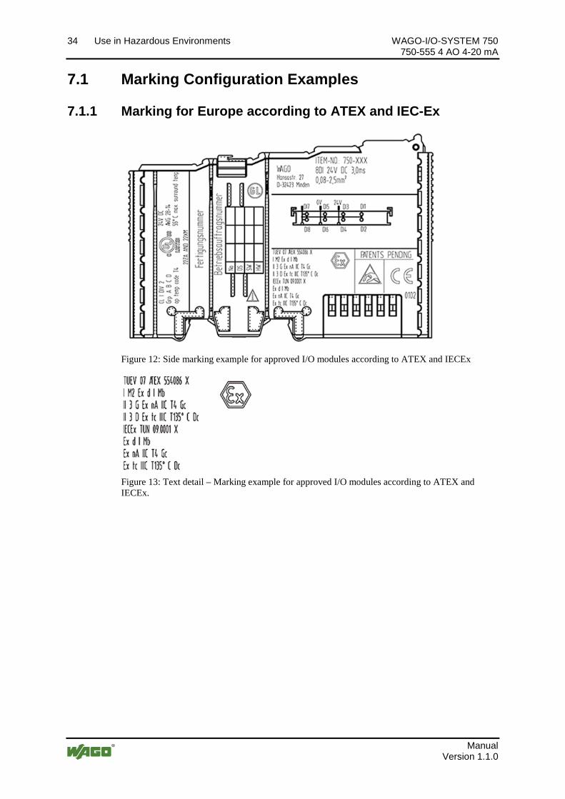
7.1.1 Marking for Europe according to ATEX and IEC-Ex Pos: 32.6 /Serie 750 (WAGO-I/O-SYSTEM)/Einsatz in Ex- Ber eichen/Beispiel bedruckung der ATEX- und IEC- Ex-zug elassenen Busklemmen gemäß C ENELEC und IEC_2013 @ 14\mod_1360569228625_21.docx @ 111294 @ @ 1
Figure 12: Side marking example for approved I/O modules according to ATEX and IECEx
Figure 13: Text detail – Marking example for approved I/O modules according to ATEX and IECEx.
WAGO-I/O-SYSTEM 750 Use in Hazardous Environments 35 750-555 4 AO 4-20 mA
Manual Version 1.1.0
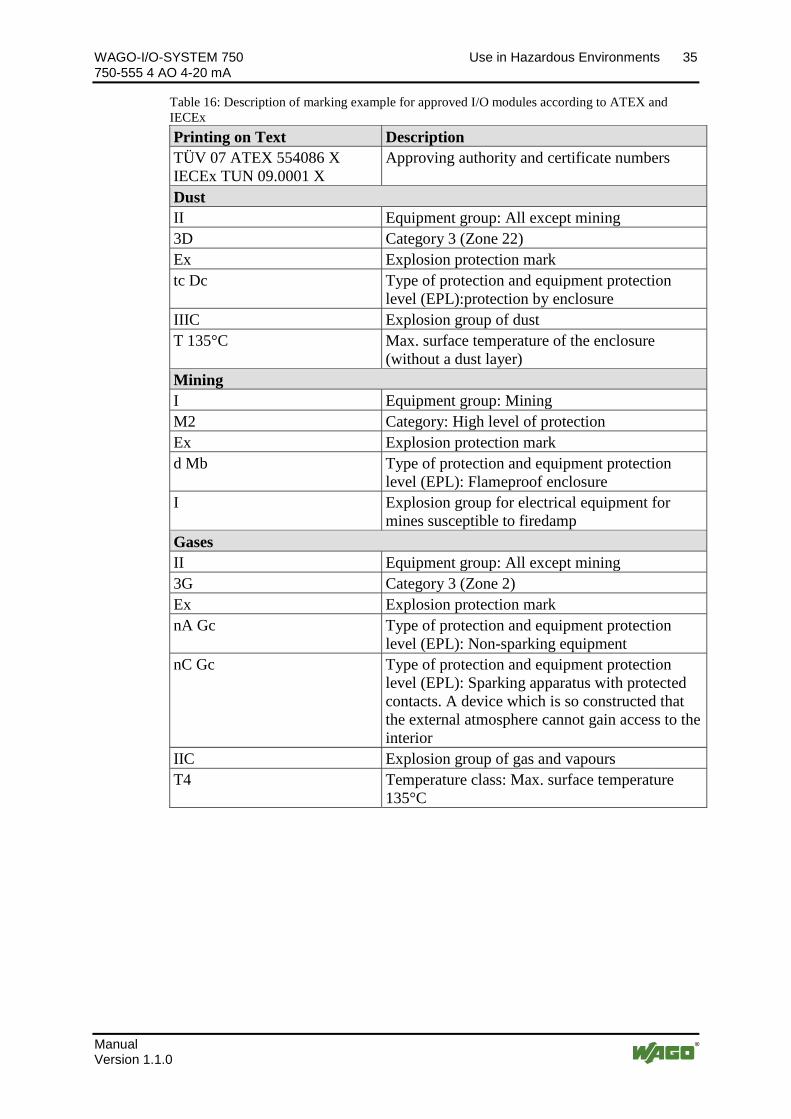
Table 16: Description of marking example for approved I/O modules according to ATEX and IECEx Printing on Text Description TÜV 07 ATEX 554086 X IECEx TUN 09.0001 X
Approving authority and certificate numbers
Dust II Equipment group: All except mining 3D Category 3 (Zone 22) Ex Explosion protection mark tc Dc Type of protection and equipment protection
level (EPL):protection by enclosure IIIC Explosion group of dust T 135°C Max. surface temperature of the enclosure
(without a dust layer) Mining I Equipment group: Mining M2 Category: High level of protection Ex Explosion protection mark d Mb Type of protection and equipment protection
level (EPL): Flameproof enclosure I Explosion group for electrical equipment for
mines susceptible to firedamp Gases II Equipment group: All except mining 3G Category 3 (Zone 2) Ex Explosion protection mark nA Gc Type of protection and equipment protection
level (EPL): Non-sparking equipment nC Gc Type of protection and equipment protection
level (EPL): Sparking apparatus with protected contacts. A device which is so constructed that the external atmosphere cannot gain access to the interior
IIC Explosion group of gas and vapours T4 Temperature class: Max. surface temperature
135°C
Pos: 32.7 /Dokumentation allgemei n/Glieder ungselemente/---Seitenwechsel--- @ 3\mod_1221108045078_0.docx @ 21810 @ @ 1
36 Use in Hazardous Environments WAGO-I/O-SYSTEM 750 750-555 4 AO 4-20 mA
Manual Version 1.1.0
Pos: 32.8 /Serie 750 (WAGO-I/O-SYSTEM)/Einsatz in Ex- Ber eichen/Beispiel bedruckung der Ex-i- und IEC-Ex-i-zug elassenen Busklemmen gemäß C ENELEC und IEC _2013 @ 14\mod_1360569320118_21.docx @ 111298 @ @ 1
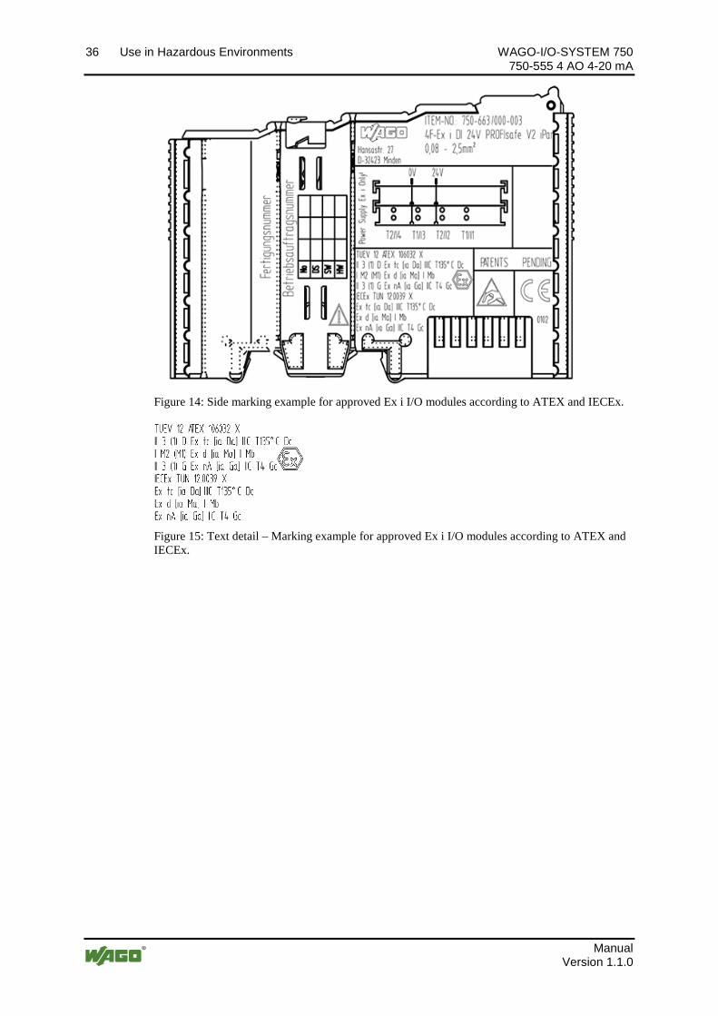
Figure 14: Side marking example for approved Ex i I/O modules according to ATEX and IECEx.
Figure 15: Text detail – Marking example for approved Ex i I/O modules according to ATEX and IECEx.
WAGO-I/O-SYSTEM 750 Use in Hazardous Environments 37 750-555 4 AO 4-20 mA
Manual Version 1.1.0
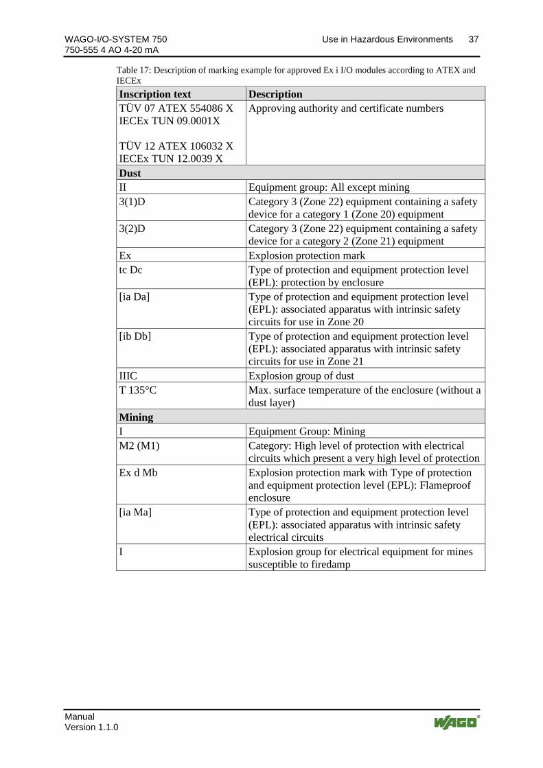
Table 17: Description of marking example for approved Ex i I/O modules according to ATEX and IECEx Inscription text Description TÜV 07 ATEX 554086 X IECEx TUN 09.0001X TÜV 12 ATEX 106032 X IECEx TUN 12.0039 X
Approving authority and certificate numbers
Dust II Equipment group: All except mining 3(1)D Category 3 (Zone 22) equipment containing a safety
device for a category 1 (Zone 20) equipment 3(2)D Category 3 (Zone 22) equipment containing a safety
device for a category 2 (Zone 21) equipment Ex Explosion protection mark tc Dc Type of protection and equipment protection level
(EPL): protection by enclosure [ia Da] Type of protection and equipment protection level
(EPL): associated apparatus with intrinsic safety circuits for use in Zone 20
[ib Db] Type of protection and equipment protection level (EPL): associated apparatus with intrinsic safety circuits for use in Zone 21
IIIC Explosion group of dust T 135°C Max. surface temperature of the enclosure (without a
dust layer) Mining I Equipment Group: Mining M2 (M1) Category: High level of protection with electrical
circuits which present a very high level of protection Ex d Mb Explosion protection mark with Type of protection
and equipment protection level (EPL): Flameproof enclosure
[ia Ma] Type of protection and equipment protection level (EPL): associated apparatus with intrinsic safety electrical circuits
I
Explosion group for electrical equipment for mines susceptible to firedamp
38 Use in Hazardous Environments WAGO-I/O-SYSTEM 750 750-555 4 AO 4-20 mA
Manual Version 1.1.0
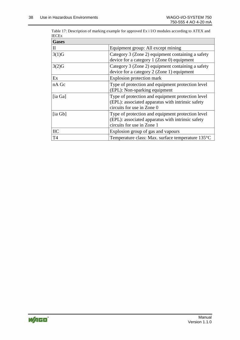
Table 17: Description of marking example for approved Ex i I/O modules according to ATEX and IECEx Gases II Equipment group: All except mining 3(1)G Category 3 (Zone 2) equipment containing a safety
device for a category 1 (Zone 0) equipment 3(2)G Category 3 (Zone 2) equipment containing a safety
device for a category 2 (Zone 1) equipment Ex Explosion protection mark nA Gc Type of protection and equipment protection level
(EPL): Non-sparking equipment [ia Ga] Type of protection and equipment protection level
(EPL): associated apparatus with intrinsic safety circuits for use in Zone 0
[ia Gb] Type of protection and equipment protection level (EPL): associated apparatus with intrinsic safety circuits for use in Zone 1
IIC Explosion group of gas and vapours T4 Temperature class: Max. surface temperature 135°C
Pos: 32.9 /Dokumentation allgemei n/Glieder ungselemente/---Seitenwechsel--- @ 3\mod_1221108045078_0.docx @ 21810 @ @ 1
WAGO-I/O-SYSTEM 750 Use in Hazardous Environments 39 750-555 4 AO 4-20 mA
Manual Version 1.1.0
Pos: 32.10 /Serie 750 ( WAGO-I/O-SYSTEM)/Ei nsatz i n Ex-Bereichen/Kennzeichnung für Ameri ka gemäß N EC 500 - Überschrift 3 @ 3\mod_1224158423187_21.docx @ 24188 @ 3 @ 1
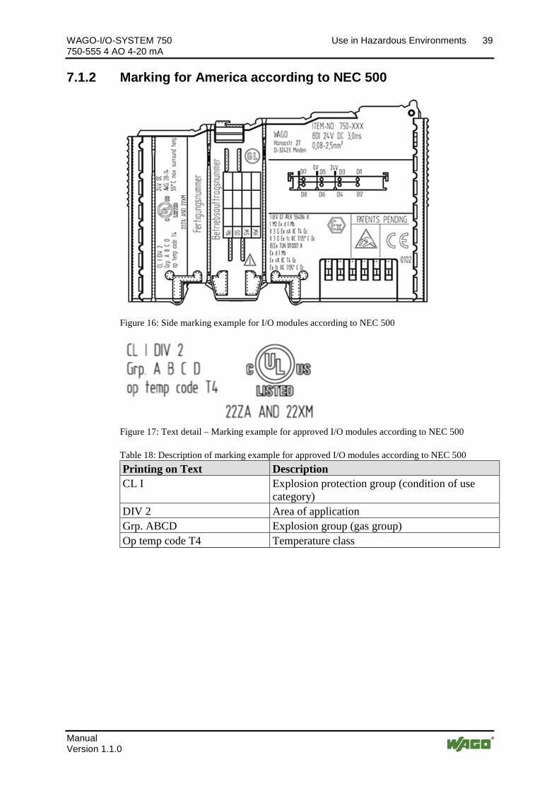
7.1.2 Marking for America according to NEC 500 Pos: 32.11 /Serie 750 ( WAGO-I/O-SYSTEM)/Ei nsatz i n Ex-Bereichen/Beispi elbedruckung gemäß NEC 500_2013 @ 14\mod_1360580302684_21.docx @ 111353 @ @ 1
Figure 16: Side marking example for I/O modules according to NEC 500
Figure 17: Text detail – Marking example for approved I/O modules according to NEC 500
Table 18: Description of marking example for approved I/O modules according to NEC 500 Printing on Text Description CL I Explosion protection group (condition of use
category) DIV 2 Area of application Grp. ABCD Explosion group (gas group) Op temp code T4 Temperature class
Pos: 32.12 /D okumentati on allgemei n/Gli ederungsel emente/---Seitenwechsel--- @ 3\mod_1221108045078_0.docx @ 21810 @ @ 1
40 Use in Hazardous Environments WAGO-I/O-SYSTEM 750 750-555 4 AO 4-20 mA
Manual Version 1.1.0
Pos: 32.13 /Alle Serien (Allgemeine M odul e)/Ei nsatz i n Ex-Bereichen/Errichtungsbes timmungen - Ü berschrift 2 @ 3\mod_1232453624234_21.docx @ 26370 @ 2 @ 1
7.2 Installation Regulations Pos: 32.14 /Alle Serien (Allgemeine M odul e)/Ei nsatz i n Ex-Bereichen/Errichtungsbes timmungen Ei nleitung_2013 @ 14\mod_1360582328318_21.docx @ 111371 @ @ 1
For the installation and operation of electrical equipment in hazardous areas, the valid national and international rules and regulations which are applicable at the installation location must be carefully followed.
Pos: 32.15 /D okumentati on allgemei n/Gli ederungsel emente/---Seitenwechsel--- @ 3\mod_1221108045078_0.docx @ 21810 @ @ 1
WAGO-I/O-SYSTEM 750 Use in Hazardous Environments 41 750-555 4 AO 4-20 mA
Manual Version 1.1.0
Pos: 32.16 /Serie 750 ( WAGO-I/O-SYSTEM)/Ei nsatz i n Ex-Bereichen/Besonder e Beding ung en für den sicher en Ex- Betrieb gem. ATEX-Zertifi kat TÜV 07 ATEX 554086_X_2013_2 @ 15\mod_1368620071975_21.docx @ 119778 @ 3 @ 1
7.2.1 Special Conditions for Safe Use (ATEX Certificate TÜV 07 ATEX 554086 X)
1. For use as Gc- or Dc-apparatus (in zone 2 or 22) the Field bus Independent I/O Modules WAGO-I/O-SYSTEM 750-*** shall be erected in an enclosure that fulfils the requirements of the applicable standards (see the marking) EN 60079-0, EN 60079-11, EN 60079-15 and EN 60079-31. For use as group I electrical apparatus M2 the apparatus shall be erected in an enclosure that ensures a sufficient protection according to EN 60079-0 and EN 60079-1 and the degree of protection IP64. The compliance of these requirements and the correct installation into an enclosure or a control cabinet of the devices shall be certified by an ExNB.
2. Measures have to be taken outside of the device that the rating voltage is not being exceeded of more than 40 % because of transient disturbances.
3. Dip-switches, binary-switches and potentiometers, connected to the module may only be actuated when explosive atmosphere can be excluded.
4. The connecting and disconnecting of the non-intrinsically safe circuits is only permitted during installation, for maintenance or for repair purposes. The temporal coincidence of explosion hazardous atmosphere and installation, maintenance resp. repair purposes shall be excluded. This is although and in particular valid for the interfaces “Memory-Card”, “USB”, “Fieldbus connection”, “Configuration and programming interface”, “antenna socket”, “D-Sub”, “DVI-port” and the “Ethernet interface”. These interfaces are not energy limited or intrinsically safe circuits. An operating of those circuits is in the behalf of the operator.
5. For the types 750-606, 750-625/000-001, 750-487/003-000, 750-484 and 750-633 the following shall be considered: The Interface circuits shall be limited to overvoltage category I/II/III (non mains/mains circuits) as defined in EN 60664-1.
6. For replaceable fuses the following shall be considered: Do not remove or replace the fuse when the apparatus is energized.
7. The following warnings shall be placed nearby the unit: WARNING – DO NOT REMOVE OR REPLACE FUSE WHEN ENERGIZED WARNING – DO NOT SEPARATE WHEN ENERGIZED WARNING – SEPARATE ONLY IN A NON-HAZARDOUS AREA
Pos: 32.17 /D okumentati on allgemei n/Gli ederungsel emente/---Seitenwechsel--- @ 3\mod_1221108045078_0.docx @ 21810 @ @ 1

42 Use in Hazardous Environments WAGO-I/O-SYSTEM 750 750-555 4 AO 4-20 mA
Manual Version 1.1.0
Pos: 32.18 /Serie 750 ( WAGO-I/O-SYSTEM)/Ei nsatz i n Ex-Bereichen/Besonder e Beding ung en für den sicher en Ex- Betrieb gem. ATEX-Zertifi kat TÜV 12 ATEX 106032x_2013_2 @ 15\mod_1368620479454_21.docx @ 119782 @ 3 @ 1
7.2.2 Special Conditions for Safe Use (ATEX Certificate TÜV 12 ATEX 106032 X)
1. For use as Gc- or Dc-apparatus (in zone 2 or 22) the Field bus Independent I/O Modules WAGO-I/O-SYSTEM 750-*** Ex i shall be erected in an enclosure that fulfils the requirements of the applicable standards (see the marking) EN 60079-0, EN 60079-11, EN 60079-15 and EN 60079-31. For use as group I electrical apparatus M2 the apparatus shall be erected in an enclosure that ensures a sufficient protection according to EN 60079-0 and EN 60079-1 and the degree of protection IP64. The compliance of these requirements and the correct installation into an enclosure or a control cabinet of the devices shall be certified by an ExNB.
2. Measures have to be taken outside of the device that the rating voltage is not being exceeded of more than 40 % because of transient disturbances.
3. The connecting and disconnecting of the non-intrinsically safe circuits is only permitted during installation, for maintenance or for repair purposes. The temporal coincidence of explosion hazardous atmosphere and installation, maintenance resp. repair purposes shall be excluded.
4. For the type the following shall be considered: The Interface circuits shall be limited to overvoltage category I/II/III (non mains/mains circuits) as defined in EN 60664-1.
Pos: 32.19 /D okumentati on allgemei n/Gli ederungsel emente/---Seitenwechsel--- @ 3\mod_1221108045078_0.docx @ 21810 @ @ 1
WAGO-I/O-SYSTEM 750 Use in Hazardous Environments 43 750-555 4 AO 4-20 mA
Manual Version 1.1.0
Pos: 32.20 /Serie 750 ( WAGO-I/O-SYSTEM)/Ei nsatz i n Ex-Bereichen/Besonder e Beding ung en für den sicher en Ex- Betrieb gem. IEC-Ex-Zertifi kat TUN 09.0001 X_2013_2 @ 15\mod_1368620660911_21.docx @ 119786 @ 3 @ 1
7.2.3 Special Conditions for Safe Use (IEC-Ex Certificate TUN 09.0001 X)
1. For use as Gc- or Dc-apparatus (in zone 2 or 22) the Field bus Independent I/O Modules WAGO-I/O-SYSTEM 750-*** shall be erected in an enclosure that fulfils the requirements of the applicable standards (see the marking) IEC 60079-0, IEC 60079-11, IEC 60079-15 and IEC 60079-31. For use as group I electrical apparatus M2 the apparatus shall be erected in an enclosure that ensures a sufficient protection according to IEC 60079-0 and IEC 60079-1 and the degree of protection IP64. The compliance of these requirements and the correct installation into an enclosure or a control cabinet of the devices shall be certified by an ExCB.
2. Measures have to be taken outside of the device that the rating voltage is not being exceeded of more than 40 % because of transient disturbances.
3. DIP-switches, binary-switches and potentiometers, connected to the module may only be actuated when explosive atmosphere can be excluded.
4. The connecting and disconnecting of the non-intrinsically safe circuits is only permitted during installation, for maintenance or for repair purposes. The temporal coincidence of explosion hazardous atmosphere and installation, maintenance resp. repair purposes shall be excluded. This is although and in particular valid for the interfaces “Memory-Card”, “USB”, “Fieldbus connection”, “Configuration and programming interface”, “antenna socket”, “D-Sub”, “DVI-port” and the “Ethernet interface”. These interfaces are not energy limited or intrinsically safe circuits. An operating of those circuits is in the behalf of the operator.
5. For the types 750-606, 750-625/000-001, 750-487/003-000, 750-484 and 750-633 the following shall be considered: The Interface circuits shall be limited to overvoltage category I/II/III (non mains/mains circuits) as defined in IEC 60664-1.
6. For replaceable fuses the following shall be considered: Do not remove or replace the fuse when the apparatus is energized.
7. The following warnings shall be placed nearby the unit: WARNING – DO NOT REMOVE OR REPLACE FUSE WHEN ENERGIZED WARNING – DO NOT SEPARATE WHEN ENERGIZED WARNING – SEPARATE ONLY IN A NON-HAZARDOUS AREA
Pos: 32.21 /D okumentati on allgemei n/Gli ederungsel emente/---Seitenwechsel--- @ 3\mod_1221108045078_0.docx @ 21810 @ @ 1
44 Use in Hazardous Environments WAGO-I/O-SYSTEM 750 750-555 4 AO 4-20 mA
Manual Version 1.1.0
Pos: 32.22 /Serie 750 ( WAGO-I/O-SYSTEM)/Ei nsatz i n Ex-Bereichen/Besonder e Beding ung en für den sicher en Ex- Betrieb gem. IEC-Ex-Zertifi kat TUN 12.0039 X_2013_2 @ 15\mod_1368620821493_21.docx @ 119790 @ 3 @ 1
7.2.4 Special Conditions for Safe Use (IEC-Ex Certificate IECEx TUN 12.0039 X)
1. For use as Gc- or Dc-apparatus (in zone 2 or 22) the Field bus independent I/O Modules WAGO-I/O-SYSTEM 750-*** Ex i shall be erected in an enclosure that fulfils the requirements of the applicable standards (see the marking) IEC 60079-0, IEC 60079-11, IEC 60079-15, IEC 60079-31. For use as group I electrical apparatus M2 the apparatus shall be erected in an enclosure that ensures a sufficient protection according to IEC 60079-0 and IEC 60079-1 and the degree of protection IP64. The compliance of these requirements and the correct installation into an enclosure or a control cabinet of the devices shall be certified by an ExCB.
2. Measures have to be taken outside of the device that the rating voltage is not being exceeded of more than 40 % because of transient disturbances.
3. The connecting and disconnecting of the non-intrinsically safe circuits is only permitted during installation, for maintenance or for repair purposes. The temporal coincidence of explosion hazardous atmosphere and installation, maintenance resp. repair purposes shall be excluded.
4. For the type the following shall be considered: The Interface circuits shall be limited to overvoltage category I/II/III (non mains/mains circuits) as defined in IEC 60664-1.
Pos: 32.23 /D okumentati on allgemei n/Gli ederungsel emente/---Seitenwechsel--- @ 3\mod_1221108045078_0.docx @ 21810 @ @ 1
WAGO-I/O-SYSTEM 750 Use in Hazardous Environments 45 750-555 4 AO 4-20 mA
Manual Version 1.1.0
Pos: 32.24 /Serie 750 ( WAGO-I/O-SYSTEM)/Ei nsatz i n Ex-Bereichen/Errichtungsbesti mmung en AN SI ISA 12.12.01_2013_2 @ 15\mod_1368620942842_21.docx @ 119794 @ 3 @ 1
7.2.5 Special Conditions for Safe Use according to ANSI/ISA 12.12.01
A. “This equipment is suitable for use in Class I, Division 2, Groups A, B, C, D or non-hazardous locations only.”
B. “This equipment is to be fitted within tool-secured enclosures only.” C. “WARNING Explosion hazard - substitution of components may impair
suitability for Class I, Div. 2.” D. “WARNING – Do not disconnect equipment unless power has been
switched off or the area is known to be non-hazardous” has to be placed near each operator accessible connector and fuse holder.
E. When a fuse is provided, the following information shall be provided: “A switch suitable for the location where the equipment is installed shall be provided to remove the power from the fuse.”
F. For devices with EtherCAT/Ethernet connectors “Only for use in LAN, not for connection to telecommunication circuits.”
G. “WARNING - Use Module 750-642 only with antenna module 758-910.” H. For Couplers/Controllers and Economy bus modules only: The instructions
shall contain the following: “The configuration interface Service connector is for temporary connection only. Do not connect or disconnect unless the area is known to be non-hazardous. Connection or disconnection in an explosive atmosphere could result in an explosion.”
I. Modules containing fuses only: “WARNING - Devices containing fuses must not be fitted into circuits subject to over loads, e.g. motor circuits.”
J. Modules containing SD card reader sockets only: “WARNING - Do not connect or disconnect SD-Card while circuit is live unless the area is known to be free of ignitable concentrations of flammable gases or vapors.”
Pos: 32.25 /D okumentati on allgemei n/Gli ederungsel emente/------Leerzeile------ @ 3\mod_1224662755687_0.docx @ 24460 @ @ 1
Pos: 32.26 /D okumentati on allgemei n/Gli ederungsel emente/------Leerzeile------ @ 3\mod_1224662755687_0.docx @ 24460 @ @ 1
Pos: 32.27 /D okumentati on allgemei n/Gli ederungsel emente/------Leerzeile------ @ 3\mod_1224662755687_0.docx @ 24460 @ @ 1
Pos: 32.28 /Serie 750 ( WAGO-I/O-SYSTEM)/Ei nsatz i n Ex-Bereichen/Infor mati on: Zer tifizier ungsnachweis @ 7\mod_1274279547729_21.docx @ 56649 @ @ 1
Additional Information Proof of certification is available on request. Also take note of the information given on the operating and assembly instructions. The manual, containing these special conditions for safe use, must be readily available to the user.
=== Ende der Liste für Textmar ke Inhalt_mitte ===
46 List of Figures WAGO-I/O-SYSTEM 750 750-555 4 AO 4-20 mA
Manual Version 1.1.0
Pos: 34 /D okumentation allgemei n/Verzeichnisse/Abbil dungsverzeichnis - Überschrift oG und Verzeichnis @ 3\mod_1219222916765_21.docx @ 21080 @ @ 1
List of Figures Figure 1: View ....................................................................................................... 15 Figure 2: Data Contacts ......................................................................................... 16 Figure 3: Power Jumper Contacts ......................................................................... 17 Figure 4: CAGE CLAMP® Connectors................................................................. 19 Figure 5: Display Elements ................................................................................... 20 Figure 6: Schematic diagram ................................................................................. 21 Figure 7: Insert I/O module (sample) .................................................................... 29 Figure 8: Snap the I/O module into place (sample) ............................................... 29 Figure 9: Removing the I/O module (sample) ....................................................... 30 Figure 10: Connecting a conductor to a CAGE CLAMP® .................................... 31 Figure 11: Connecting diagram ............................................................................. 32 Figure 12: Side marking example for approved I/O modules according to ATEX
and IECEx .................................................................................................... 34 Figure 13: Text detail – Marking example for approved I/O modules according to
ATEX and IECEx. ....................................................................................... 34 Figure 14: Side marking example for approved Ex i I/O modules according to
ATEX and IECEx. ....................................................................................... 36 Figure 15: Text detail – Marking example for approved Ex i I/O modules
according to ATEX and IECEx. .................................................................. 36 Figure 16: Side marking example for I/O modules according to NEC 500 .......... 39 Figure 17: Text detail – Marking example for approved I/O modules according to
NEC 500....................................................................................................... 39
Pos: 35 /D okumentation allgemei n/Glieder ungselemente/---Seitenwechsel--- @ 3\mod_1221108045078_0.docx @ 21810 @ @ 1
WAGO-I/O-SYSTEM 750 List of Tables 47 750-555 4 AO 4-20 mA
Manual Version 1.1.0
Pos: 36 /D okumentation allgemei n/Verzeichnisse/Tabell enverzeichnis - Überschrift oG und Verzeichnis @ 3\mod_1219222958703_21.docx @ 21084 @ @ 1
List of Tables Table 1: Number notation ........................................................................................ 8 Table 2: Font conventions ....................................................................................... 8 Table 3: Legend for the “View” Figure ................................................................. 15 Table 4: Legend for the “Power Jumper Contacts” Figure ................................... 17 Table 5: Legend for the “CAGE CLAMP® Connectors” Figure ......................... 19 Table 6: Legend for the “Display Elements” Figure ............................................. 20 Table 7: Technical Data – Device ......................................................................... 22 Table 8: Technical Data, Power Supply ................................................................ 22 Table 9: Technical Data, Communication ............................................................. 22 Table 10: Technical Data, Outputs ........................................................................ 22 Table 11: Technical Data – Field Wiring .............................................................. 23 Table 12: Technical Data – Power Jumper Contacts ............................................ 23 Table 13: Technical Data – Data contacts ............................................................. 23 Table 14: Technical Data – Climatic Environmental Conditions ......................... 23 Tabelle 15: Process Image ..................................................................................... 27 Table 16: Description of marking example for approved I/O modules according to
ATEX and IECEx ........................................................................................ 35 Table 17: Description of marking example for approved Ex i I/O modules
according to ATEX and IECEx ................................................................... 37 Table 18: Description of marking example for approved I/O modules according to
NEC 500....................................................................................................... 39
=== Ende der Liste für Textmar ke Verzeichnis_hi nten ===

Pos: 38 /D okumentation allgemei n/Einband/Einband H andbuch - R ückseite @ 9\mod_1285229376516_21.docx @ 64944 @ @ 1
WAGO Kontakttechnik GmbH & Co. KG Postfach 2880 • D-32385 Minden Hansastraße 27 • D-32423 Minden Phone: +49/5 71/8 87 – 0 Fax: +49/5 71/8 87 – 1 69 E-Mail: [email protected] Internet: http://www.wago.com
=== Ende der Liste für Textmar ke Ei nband_hinten ===