MASCHINENBAU - Lean Factory America · BKLS Maschinenbau Seite 3 von 7 Advance Manual Designate Use...
8
BKLS MASCHINENBAU - Lifter PNH – 0250 – 0800 – ST PNH – 0200 – 0800 – ST Status:2015/03
Transcript of MASCHINENBAU - Lean Factory America · BKLS Maschinenbau Seite 3 von 7 Advance Manual Designate Use...
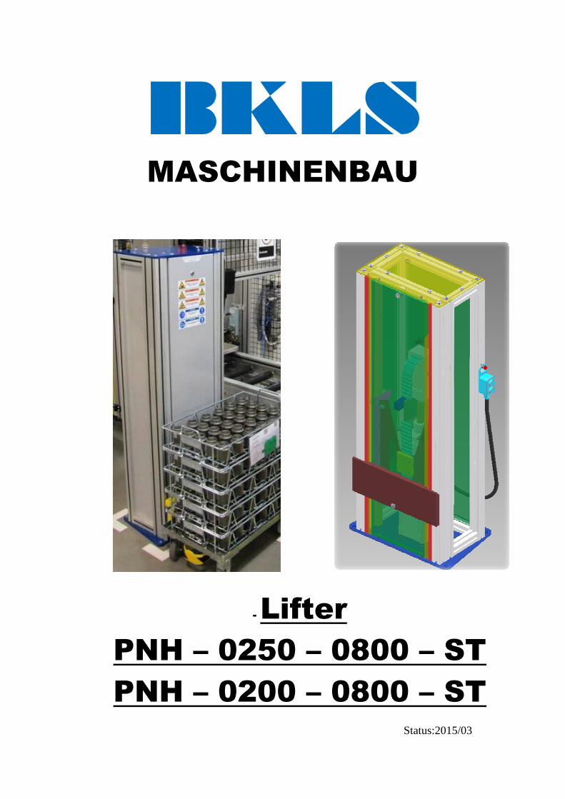
BKLS MASCHINENBAU
- Lifter
PNH – 0250 – 0800 – ST
PNH – 0200 – 0800 – ST
Status:2015/03
BKLS Maschinenbau
Seite 2 von 7
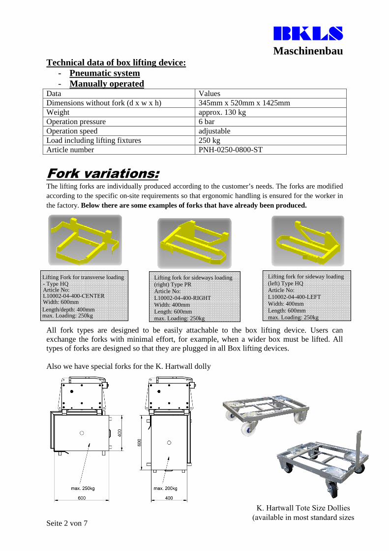
Technical data of box lifting device: - Pneumatic system- Manually operated
Data Values Dimensions without fork (d x w x h) 345mm x 520mm x 1425mm Weight approx. 130 kg Operation pressure 6 bar Operation speed adjustable Load including lifting fixtures 250 kg Article number PNH-0250-0800-ST
Fork variations: The lifting forks are individually produced according to the customer’s needs. The forks are modified according to the specific on-site requirements so that ergonomic handling is ensured for the worker in the factory. Below there are some examples of forks that have already been produced.
Al l fork types are designed to be easily attachable to the box lifting device. Users can exchange the forks with minimal effort, for example, when a wider box must be lifted. All types of forks are designed so that they are plugged in all Box lifting devices.
Also we have special forks for the K. Hartwall dolly
Lifting Fork for transverse l oading - Type HQ Article No: L10002-04-400-CENTER Width: 600mm Length/depth: 400mm max. Loading: 250kg
Lifting fork for sideways loading (right) Type PR Article No: L10002-04-400-RIGHT Width: 400mm Length: 600mm max. Loading: 250kg
Lifting fork for sideway loading (left) Type HQ Article No:L10002-04-400-LEFTWidth: 400mm Length: 600mm max. Loading: 250kg
K. Hartwall Tote Size Dollies(available in most standard sizes
BKLS Maschinenbau
Seite 3 von 7
Advance Manual
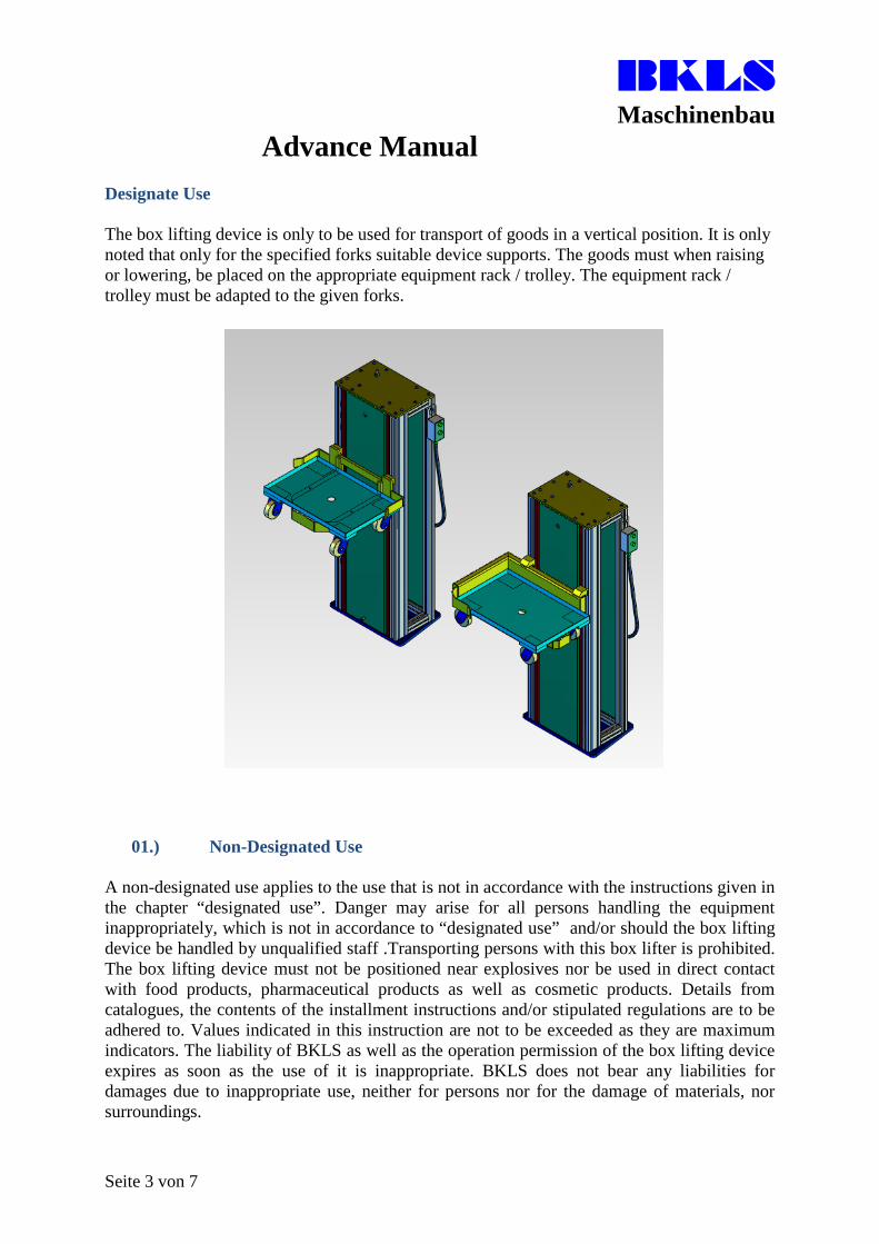
Designate Use
The box lifting device is only to be used for transport of goods in a vertical position. It is only noted that only for the specified forks suitable device supports. The goods must when raising or lowering, be placed on the appropriate equipment rack / trolley. The equipment rack / trolley must be adapted to the given forks.
01.) Non-Designated Use
A non-designated use applies to the use that is not in accordance with the instructions given in the chapter “designated use”. Danger may arise for all persons handling the equipment inappropriately, which is not in accordance to “designated use” and/or should the box lifting device be handled by unqualified staff .Transporting persons with this box lifter is prohibited. The box lifting device must not be positioned near explosives nor be used in direct contact with food products, pharmaceutical products as well as cosmetic products. Details from catalogues, the contents of the installment instructions and/or stipulated regulations are to be adhered to. Values indicated in this instruction are not to be exceeded as they are maximum indicators. The liability of BKLS as well as the operation permission of the box lifting device expires as soon as the use of it is inappropriate. BKLS does not bear any liabilities for damages due to inappropriate use, neither for persons nor for the damage of materials, nor surroundings.
BKLS Maschinenbau
Seite 4 von 7
02.) Reasonably Foreseeable Misuse
• Operation outdoors• Operation in rooms with high humidity• Opening of the equipment• Use with inefficiently safe flooring• Operating the equipment while pneumatic tubes or case is damaged• Unsecured lifting fork• Impacts coming from the side must not cause a falling over
04.) Authorized Operation of the Box Lifting Device
Persons that have fully studied und understood the instructions may operate the box lifting device, mount it and operate it. Responsibilities must be clearly defined in advance to operation and adhered to.
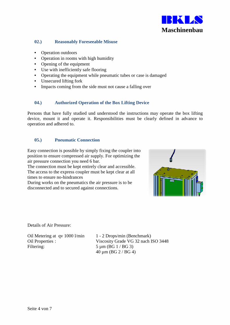
05.) Pneumatic Connection
Easy connection is possible by simply fixing the coupler into position to ensure compressed air supply. For optimizing the air pressure connection you need 6 bar. The connection must be kept entirely clear and accessible. The access to the express coupler must be kept clear at all times to ensure no-hindrances During works on the pneumatics the air pressure is to be disconnected and to secured against connections.
Details of Air Pressure:
Oil Metering at qv 1000 l/min 1 - 2 Drops/min (Benchmark) Oil Properties : Viscosity Grade VG 32 nach ISO 3448 Filtering: 5 µm (BG 1 / BG 3)
40 µm (BG 2 / BG 4)
BKLS Maschinenbau
Seite 5 von 7
06.) Functions and Loading of Box Lifting Device
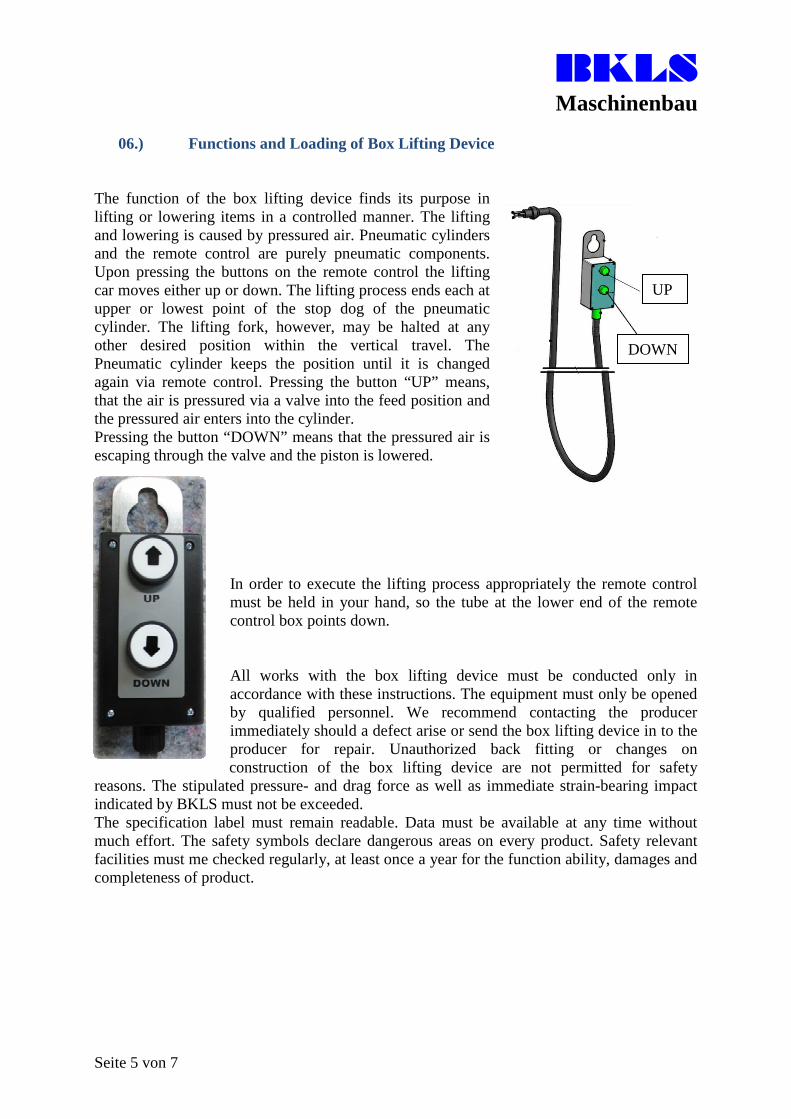
The function of the box lifting device finds its purpose in lifting or lowering items in a controlled manner. The lifting and lowering is caused by pressured air. Pneumatic cylinders and the remote control are purely pneumatic components. Upon pressing the buttons on the remote control the lifting car moves either up or down. The lifting process ends each at upper or lowest point of the stop dog of the pneumatic cylinder. The lifting fork, however, may be halted at any other desired position within the vertical travel. The Pneumatic cylinder keeps the position until it is changed again via remote control. Pressing the button “UP” means, that the air is pressured via a valve into the feed position and the pressured air enters into the cylinder. Pressing the button “DOWN” means that the pressured air is escaping through the valve and the piston is lowered.
In order to execute the lifting process appropriately the remote control must be held in your hand, so the tube at the lower end of the remote control box points down.
All works with the box lifting device must be conducted only in accordance with these instructions. The equipment must only be opened by qualified personnel. We recommend contacting the producer immediately should a defect arise or send the box lifting device in to the producer for repair. Unauthorized back fitting or changes on construction of the box lifting device are not permitted for safety
reasons. The stipulated pressure- and drag force as well as immediate strain-bearing impact indicated by BKLS must not be exceeded. The specification label must remain readable. Data must be available at any time without much effort. The safety symbols declare dangerous areas on every product. Safety relevant facilities must me checked regularly, at least once a year for the function ability, damages and completeness of product.
UP
DOWN
BKLS Maschinenbau
Seite 6 von 7
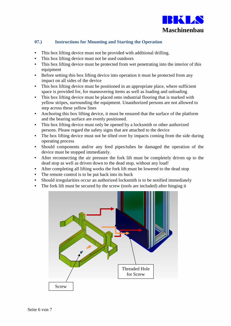
07.) Instructions for Mounting and Starting the Operation
• This box lifting device must not be provided with additional drilling.• This box lifting device must not be used outdoors• This box lifting device must be protected from wet penetrating into the interior of this
equipment• Before setting this box lifting device into operation it must be protected from any
impact on all sides of the device• This box lifting device must be positioned in an appropriate place, where sufficient
space is provided for, for maneuvering items as well as loading and unloading• This box lifting device must be placed onto industrial flooring that is marked with
yellow stripes, surrounding the equipment. Unauthorized persons are not allowed tostep across these yellow lines
• Anchoring this box lifting device, it must be ensured that the surface of the platformand the bearing surface are evenly positioned.
• This box lifting device must only be opened by a locksmith or other authorizedpersons. Please regard the safety signs that are attached to the device
• The box lifting device must not be tilted over by impacts coming from the side duringoperating process
• Should components and/or any feed pipes/tubes be damaged the operation of thedevice must be stopped immediately.
• After reconnecting the air pressure the fork lift must be completely driven up to thedead stop as well as driven down to the dead stop, without any load!
• After completing all lifting works the fork lift must be lowered to the dead stop• The remote control is to be put back into its buck• Should irregularities occur an authorized locksmith is to be notified immediately• The fork lift must be secured by the screw (tools are included) after hinging it
Screw
Threaded Hole for Screw
BKLS Maschinenbau
Seite 7 von 7
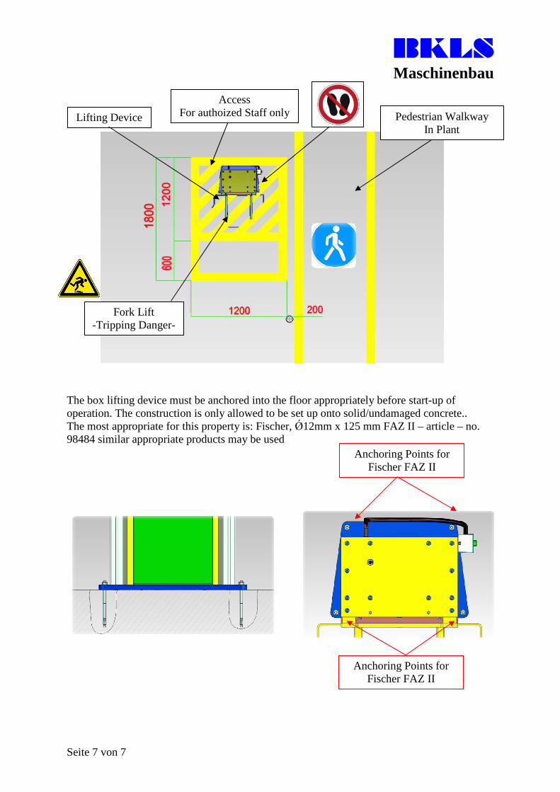
The box lifting device must be anchored into the floor appropriately before start-up of operation. The construction is only allowed to be set up onto solid/undamaged concrete.. The most appropriate for this property is: Fischer, Ǿ12mm x 125 mm FAZ II – article – no. 98484 similar appropriate products may be used
Access For authoized Staff only Lifting Device Pedestrian Walkway
In Plant
Fork Lift -Tripping Danger-
Anchoring Points for Fischer FAZ II
Anchoring Points for Fischer FAZ II
For over 40 years, Orgatex has provided durable and innovative visual management tools for implementation of 5S and optimization of lean processes.
K. Hartwall is the global front runner in returnable goods carriers since 1932. The adapter pallet and dolly system reduces waste and minimizes fork lift traffic while protecting products during shipping.
The original aluminum tube system, Green Frame, was developed to help manufacturers in all industries become more competitive by supporting Kaizen activities and enabling Karakuri.
Move roll containers and other rolling objects, simply and without physical effort, with the Movexx line of compact and ultra user-friendly push/pull assistants.
The Asutec family of pallet stops, precision locating devices and traffic control elements enables reliable material transportation and workpieceflow throughout your manufacturing process.
Nitto Kohki’s “delvo” electric screwdrivers are high-quality tools for professional use, with special emphasis on precise torque control and long-term reliability. “delvo” gives you the ability to get it right, every time.
Lean Factory’s line of branded products, including powered conveyor media such as chains and belts, are functional and interchangeable equivalents to OEM supplied parts.
Green Frame