
medan pmeumatic 01072013 korrex - ibgengineering.net · Ihre Ansprechpartner Contact Persons...
70
www.medan-gmbh.com
Transcript of medan pmeumatic 01072013 korrex - ibgengineering.net · Ihre Ansprechpartner Contact Persons...
www.medan-gmbh.com


Antonio MartinezGeschäftsführerManaging Director

Ihre Ansprechpartner Contact Persons
Vertrieb SalesHerr Igor Fabijanec
Vertrieb SalesHerr Christian Neubauer
Einkauf PurchasingHerr Thomas Stuber
QualitätskontrolleQuality managementHerr Alwin Baumann
ProduktionsleiterProduction supervisorHerr Matthias Seiffer
VersandShippingHerr Andreas Lang
Design by
KontrastPlus GmbH & Co. KGBraikestraße 4
D-72793 Pfullingen
Tel.: 07121 / 9393-590
Fax: 07121 / 9393-591
www.kontrastplus.net
Die MEDAN GmbH ist ein inhabergeführtes Familienun-
ternehmen mit innovativen Marktstrategien und großem
technischen Know-how. 1992 gegründet, hat es sich auf die
Herstellung und die Vermarktung linearer Antriebe für die
Automatisierung einfacher und komplexer Arbeitsabläufe
spezialisiert. Stammsitz und Produktionsstätte ist die tra-
ditionsbewusste Ortschaft Bempflingen bei Reutlingen.
MEDAN ist Profi auf dem Gebiet der pneumatisch bzw. elek-
trisch betriebenen Lineartechnik. Als flexibles und leis-
tungsstarkes Unternehmen versteht MEDAN die Umsetzung
von Sonderwünschen seiner Kunden als selbstverständli-
che Serviceleistung und führt die gestellten Aufgaben stets
zuverlässig in Bezug auf Funktionalität, Qualität und Liefer-
treue aus – und das zu marktgerechten Preisen. Das macht
MEDAN-Produkte vielseitig und weltweit einsetzbar.
Qualität bedeutet für MEDAN nicht nur das Erfüllen indi-
vidueller Kundenwünsche, sondern einen Service, der
diese bei weitem übertrifft. Auch bei Sonderlösungen ga-
rantieren wir kurze Lieferzeiten. Als Systemlieferant und
Entwicklungspartner analysieren wir die Aufgabenstellun-
gen unserer Kunden gründlich und arbeiten konsequent in
eine Richtung – linear. Wir bewegen linear. Sie profitieren
von unseren Stärken: Langjährige Erfahrung. Breites Pro-
duktspektrum, hochwertige Einzelteile, schnelle und inno-
vative Entwicklungsprozesse, die auf Fachkompetenz und
breit angelegter Erfahrung beruhen.
Im Gegensatz zur allgemeinen Entwicklung in der deut-
schen Industrielandschaft setzt MEDAN konsequent auf
den Produktionsstandort Deutschland und wird auch in
Zukunft daran festhalten. Die Anfertigung der Zylinder
verläuft professionell und zuverlässig im eigenen Haus –
ein Qualitätsmerkmal für das Gütesiegel „Made in Germa-
ny“. MEDAN zeichnet sich jedoch nicht nur durch qualita-
tiv hochwertige Produkte aus, sondern auch konsequent
durch seine Markenphilosophie, die ständig ausgebaut
und intensiv kommuniziert wird.
Sie profitieren von unseren Angeboten durch ein vorteilhaf-
tes Preis-Leistungsverhältnis, durch niedrige Gemeinkos-
ten, kurze Lieferzeiten und hohe Liefertreue. Wir pflegen
eine zuverlässige Bindung zu unseren Partnern, Dadurch
sind wir der Konkurrenz gerne einen linearen Schritt vor-
aus. Gemeinsam mit ihnen entwickeln wir in der Antriebs-
technik marktgerechte Produkte weiter und minimieren
Stillstandzeiten und Kosten durch einen geringen Reapa-
ratur- und Instandhaltungsaufwand. Außerdem achten wir
bei der Entwicklung neuer Produkte darauf, vorhandene,
bewährte Bauteile und Baugruppen von hoher Lebensdau-
er in den Prozess mit einzubeziehen, was ihnen auf der In-
vestitionsseite zu Gute kommt.
MEDAN GmbH, a privately owned family business with
innovative marketing strategies and extensive technical
know-how. Founded in 1992, it has focused on the manufac-
ture and marketing of linear actuators for the automation
of simple and complex specialized work processes. Head-
quarters and production facility is the tradition-conscious
town Bempflingen near to Reutlingen.
MEDAN is a professional in the field of pneumatic or elec-
tric linear technology. As a flexible and efficient company
understands MEDAN the implementation of special requi-
rements of its customers as a natural service and performs
the tasks always reliable in terms of functionality, quality
and delivery of - and at competitive prices. MEDAN-pro-
ducts makes the versatile and can be used worldwide.
Quality to MEDAN not only means fulfilling individual cli-
ents requests, but with a service that comprehensively ex-
ceed expectation. Also for special-purpose solutions, we
guarantee a short delivery time.
As system developer and supplier, we analyse our clients
needs and work as partner in one direction - linear. We keep
things moving linear!
You profit from our strength with in excess of 20 years of
experience, a large range of products, high quality com-
ponents, fast and innovative development processes, all
based on professional competence with a wide structured
know-how.
Against the common trend within the German industrial
landscape, MEDAN is comitted to Germany as its produc-
tion site, now and in the future . The production of each
cylinder is produced and controlled in house - carrying a
„Made in Germany“ seal of approval for your ultimate con-
fidence.
MEDAN is characterised not only for high quality products
but also consistently for its philosophy of the market, which
is permanently extended and communicated intensively
You benefit from MEDAN’s service due to low overhead
costs, short lead times and dependable delivery we are
able to offer the optimum price-perfomance ratio . We
maintain a customer focussed approach, thus we are a li-
near step ahead of the competition. Together we develop
in drive technology industry, marketing products that have
minimal downtime and cost, with the smallest maintenance
expenses. We operate a continuous improvement program,
developing existing and new products utilising proven com-
ponents ensuring you get the best, most reliable product at
the right price.
2
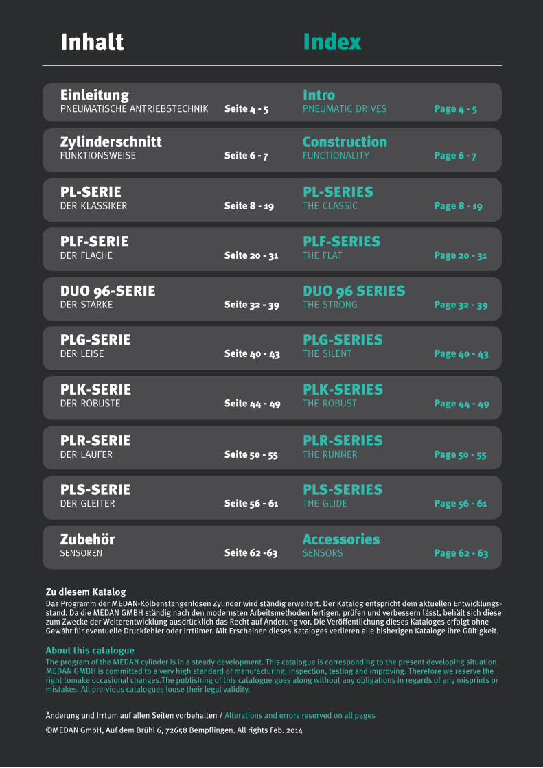
Inhalt Index
IntroPNEUMATIC DRIVES Page 4 - 5
PL-SERIESTHE CLASSIC Page 8 - 19
PL-SERIEDER KLASSIKER Seite 8 - 19
ConstructionFUNCTIONALITY Page 6 - 7
ZylinderschnittFUNKTIONSWEISE Seite 6 - 7
Einleitung PNEUMATISCHE ANTRIEBSTECHNIK Seite 4 - 5
PLF-SERIESTHE FLAT Page 20 - 31
PLF-SERIEDER FLACHE Seite 20 - 31
DUO 96 SERIESTHE STRONG Page 32 - 39
DUO 96-SERIEDER STARKE Seite 32 - 39
PLG-SERIESTHE SILENT Page 40 - 43
PLG-SERIEDER LEISE Seite 40 - 43
PLK-SERIESTHE ROBUST Page 44 - 49
PLK-SERIEDER ROBUSTE Seite 44 - 49
PLR-SERIESTHE RUNNER Page 50 - 55
PLR-SERIEDER LÄUFER Seite 50 - 55
PLS-SERIESTHE GLIDE Page 56 - 61
PLS-SERIEDER GLEITER Seite 56 - 61
AccessoriesSENSORS Page 62 - 63
ZubehörSENSOREN Seite 62 -63
Zu diesem KatalogDas Programm der MEDAN-Kolbenstangenlosen Zylinder wird ständig erweitert. Der Katalog entspricht dem aktuellen Entwicklungs-stand. Da die MEDAN GMBH ständig nach den modernsten Arbeitsmethoden fertigen, prüfen und verbessern lässt, behält sich diese zum Zwecke der Weiterentwicklung ausdrücklich das Recht auf Änderung vor. Die Veröffentlichung dieses Kataloges erfolgt ohne Gewähr für eventuelle Druckfehler oder Irrtümer. Mit Erscheinen dieses Kataloges verlieren alle bisherigen Kataloge ihre Gültigkeit.
About this catalogueThe program of the MEDAN cylinder is in a steady development. This catalogue is corresponding to the present developing situation.MEDAN GMBH is committed to a very high standard of manufacturing, inspection, testing and improving. Therefore we reserve the right tomake occasional changes.The publishing of this catalogue goes along without any obligations in regards of any misprints or mistakes. All pre-vious catalogues loose their legal validity.
Änderung und Irrtum auf allen Seiten vorbehalten / Alterations and errors reserved on all pages
©MEDAN GmbH, Auf dem Brühl 6, 72658 Bempflingen. All rights Feb. 2014
4
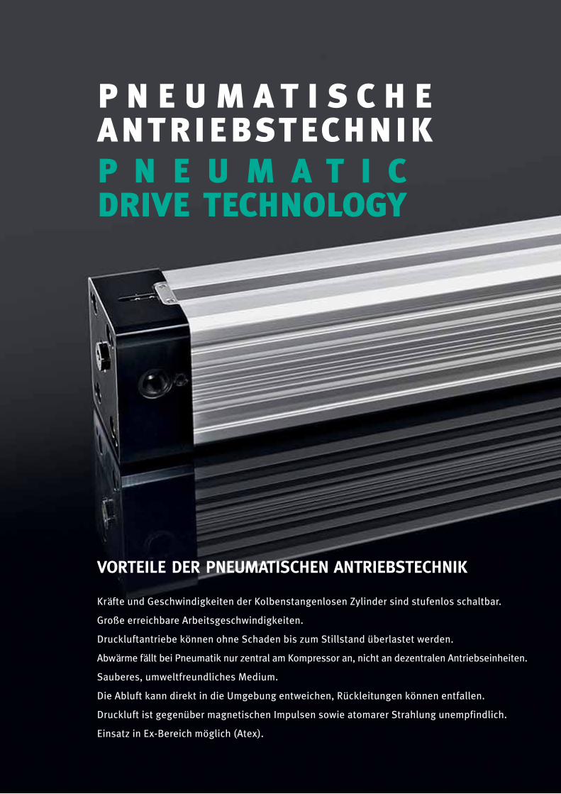
VORTEILE DER PNEUMATISCHEN ANTRIEBSTECHNIK
Kräfte und Geschwindigkeiten der Kolbenstangenlosen Zylinder sind stufenlos schaltbar.
Große erreichbare Arbeitsgeschwindigkeiten.
Druckluftantriebe können ohne Schaden bis zum Stillstand überlastet werden.
Abwärme fällt bei Pneumatik nur zentral am Kompressor an, nicht an dezentralen Antriebseinheiten.
Sauberes, umweltfreundliches Medium.
Die Abluft kann direkt in die Umgebung entweichen, Rückleitungen können entfallen.
Druckluft ist gegenüber magnetischen Impulsen sowie atomarer Strahlung unempfindlich.
Einsatz in Ex-Bereich möglich (Atex).
P N E U M A T I S C H EANTRIEBSTECHNIKP N E U M A T I CDRIVE TECHNOLOGY

ADVANTAGES OF PNEUMATIC DRIVE TECHNOLOGY
Force and speed of the rodless cylinder are directly switchable.
Great attainable operating speed.
Rodless cylinders are able to be overloaded without damage.
Waste heat is centrallised at the compressor, not at the decentralised drive units.
Clean, environmentally friendly medium.
The waste air can be exhausted directly to surrounding atmosphere.
Compressed air is insensitive in the proximity of both magnetic impulses and atomic radiation.
Use in EX - area possible (Atex.)

6 Version 02/2014
ConstructionZylinderschnitt
Dichtband innenInner sealing band
Dichtband außenOuter sealing band
ZylinderkopfCylinder head
ZylinderrohrCylinder tube
KolbenPiston
MagnetstreifenMagnet stripes
7Version 02/2014
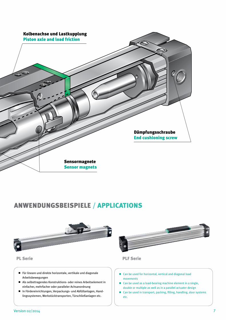
Für lineare und direkte horizontale, vertikale und diagonale
Arbeitsbewegungen
Als selbsttragendes Konstruktions- oder reines Arbeitselement in
einfacher, mehrfacher oder paralleler Achsanordnung
In Fördereinrichtungen, Verpackungs- und Abfüllanlagen, Hand-
lingssystemen, Werkstücktransporten, Türschließanlagen etc.
Can be used for horizontal, vertical and diagonal load
movements
Can be used as a load-bearing machine element in a single,
double or multiple as well as in a parallel actuater design
Can be used in transport, packing, filling, handling, door systems
etc.
ANWENDUNGSBEISPIELE / APPLICATIONS
PL Serie PLF Serie
Kolbenachse und LastkupplungPiston axle and load friction
SensormagneteSensor magnets
DämpfungsschraubeEnd cushioning screw

8 Version 02/2014
PLPL-SERIESTHE CLASSIC
PL-
SER
IE
DER KLASSIKER
The entire tube is slotted throughout its full length. The force is transmitted through the load friction, which is attached to the pis-ton axle.The design of the piston axle is that way that the inner part of the piston axle is connected through the slot with the outer part of it.
Therefore the force transmission runs as follows:Air pressure > Piston area > piston axle (inner part) > piston axle (outer part) > load friction > load.The sealing of the cylinder slot is garanteed by a most precisely grinded inner steel band. The inner band is kept in position due to magnet stripes which are placed on both sides of the slot. In addi-tion there is an outer steel band covering the slot in order to keep dust out of inner space of the cylinder.
During piston movement as well as during stillstand of it both steel-bands are lifted right after the piston seal and led through the pis-ton axle by means of a separate own guiding chanel. Before and behind the piston axle both bands are covering the slot permanent-ly again.
Das Zylinderrohr ist achsial durchgehend geschlitzt. Die Kraftab-gabe erfolgt über eine Lastkupplung, welche an der Kolbenachse befestigt ist; letztere ist so ausgebildet, dass ein durch den Rohr-schlitz geführter Steg den inneren Teil der Kolbenachse mit dem äußeren Teil verbindet.
Der Kraftverlauf ist also:Luftdruck > Kolbenfläche>Kolbenachse (innen) → Kolbenachse (außen)>Lastkupplung >Werkstück.Die druckfeste Abdichtung des Zylinderschlitzes wird mit einem präzisionsgeschliffenen, innen liegenden Stahlband erreicht; die-ses wird mit 2 längs des Schlitzes verlaufenden Magnetstreifen in Position gehalten.
Ein zweites Stahlband befindet sich außen auf dem Schlitz des Roh-res. Es dient der Staubabdeckung. Beide Stahlbänder werden wäh-rend der Kolbenfahrt genauso wie bei Stillstand hinter der Kolben-dichtung vom Schlitz abgehoben und jeweils mittels eines eigenen Führungskanales durch die Kolbenachse geleitet. Davor und dahin-ter legen sich die Bänder wieder dichtend über den Zylinderschlitz.
9Version 02/2014
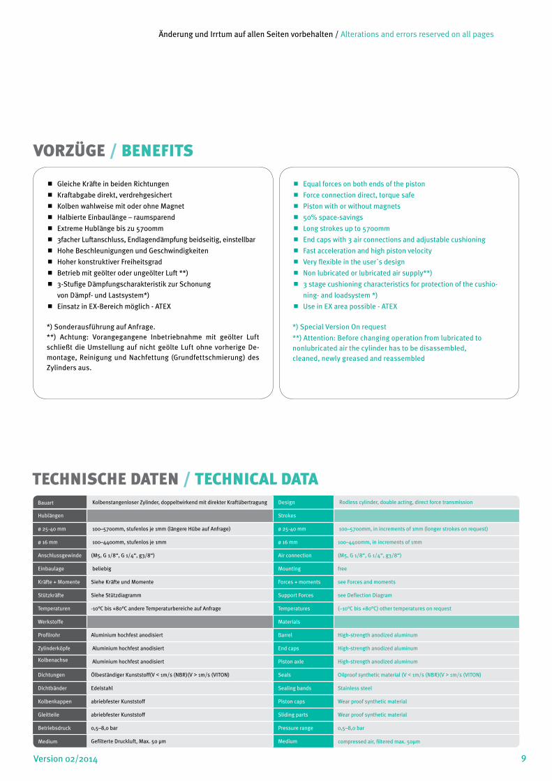
Gleiche Kräfte in beiden Richtungen
Kraftabgabe direkt, verdrehgesichert
Kolben wahlweise mit oder ohne Magnet
Halbierte Einbaulänge – raumsparend
Extreme Hublänge bis zu 5700mm
3facher Luftanschluss, Endlagendämpfung beidseitig, einstellbar
Hohe Beschleunigungen und Geschwindigkeiten
Hoher konstruktiver Freiheitsgrad
Betrieb mit geölter oder ungeölter Luft **)
3-Stufige Dämpfungscharakteristik zur Schonung
von Dämpf- und Lastsystem*)
Einsatz in EX-Bereich möglich - ATEX
*) Sonderausführung auf Anfrage.**) Achtung: Vorangegangene Inbetriebnahme mit geölter Luft schließt die Umstellung auf nicht geölte Luft ohne vorherige De-montage, Reinigung und Nachfettung (Grundfettschmierung) des Zylinders aus.
Equal forces on both ends of the piston
Force connection direct, torque safe
Piston with or without magnets
50% space-savings
Long strokes up to 5700mm
End caps with 3 air connections and adjustable cushioning
Fast acceleration and high piston velocity
Very flexible in the user`s design
Non lubricated or lubricated air supply**)
3 stage cushioning characteristics for protection of the cushio-
ning- and loadsystem *)
Use in EX area possible - ATEX
*) Special Version On request
**) Attention: Before changing operation from lubricated tononlubricated air the cylinder has to be disassembled,cleaned, newly greased and reassembled
VORZÜGE / BENEFITS
TECHNISCHE DATEN / TECHNICAL DATABauart Kolbenstangenloser Zylinder, doppeltwirkend mit direkter Kraftübertragung Design Rodless cylinder, double acting, direct force transmission
Hublängen Strokes
ø 25-40 mm 100–5700mm, stufenlos je 1mm (längere Hübe auf Anfrage) ø 25-40 mm 100–5700mm, in increments of 1mm (longer strokes on request)
ø 16 mm 100–4400mm, stufenlos je 1mm ø 16 mm 100–4400mm, in increments of 1mm
Anschlussgewinde (M5, G 1/8“, G 1/4“, g3/8“) Air connection (M5, G 1/8“, G 1/4“, g3/8“)
Einbaulage beliebig Mounting free
Kräfte + Momente Siehe Kräfte und Momente Forces + moments see Forces and moments
Stützkräfte Siehe Stützdiagramm Support Forces see Deflection Diagram
Temperaturen -10°C bis +80°C andere Temperaturbereiche auf Anfrage Temperatures (–10°C bis +80°C) other temperatures on request
Werkstoffe Materials
Profilrohr Aluminium hochfest anodisiert Barrel High-strength anodized aluminum
Zylinderköpfe Aluminium hochfest anodisiert End caps High-strength anodized aluminum
Kolbenachse Aluminium hochfest anodisiert Piston axle High-strength anodized aluminum
Dichtungen Ölbeständiger Kunststoff(V < 1m/s (NBR)(V > 1m/s (VITON) Seals Oilproof synthetic material (V < 1m/s (NBR)(V > 1m/s (VITON)
Dichtbänder Edelstahl Sealing bands Stainless steel
Kolbenkappen abriebfester Kunststoff Piston caps Wear proof synthetic material
Gleitteile abriebfester Kunststoff Sliding parts Wear proof synthetic material
Betriebsdruck 0,5–8,0 bar Pressure range 0,5–8,0 bar
Medium Gefilterte Druckluft, Max. 50 µm Medium compressed air, filtered max. 50µm
Änderung und Irrtum auf allen Seiten vorbehalten / Alterations and errors reserved on all pages
10 Version 02/2014
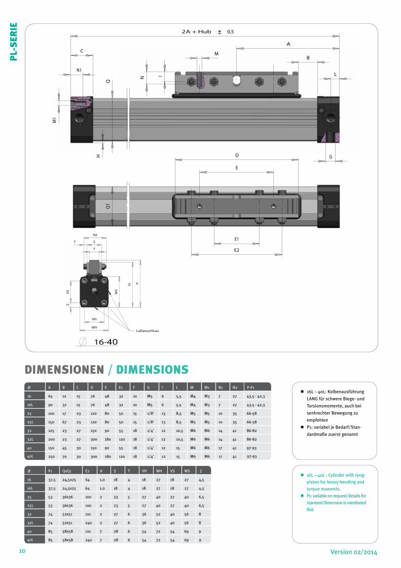
Ø A B C D E E1 F G I L M M1 N1 N2 P-P1
16 65 12 15 76 48 32 10 M5 6 5,5 M4 M3 7 27 43,5 - 42,3
16L 90 37 15 76 48 32 10 M5 6 5,5 M4 M3 7 27 43,5 - 42,3
25 100 17 23 120 80 50 15 1/8‘ 13 8,5 M5 M5 10 35 66-58
25L 150 67 23 120 80 50 15 1/8‘ 13 8,5 M5 M5 10 35 66-58
32 125 23 27 150 90 55 18 1/4‘ 12 10,5 M6 M6 14 41 86-82
32L 200 23 27 300 180 120 18 1/4‘ 12 10,5 M6 M6 14 41 86-82
40 150 45 30 150 90 55 18 1/4‘ 12 15 M6 M6 17 41 97-93
40L 250 70 30 300 180 120 18 1/4‘ 12 15 M6 M6 17 41 97-93
DIMENSIONEN / DIMENSIONS
16L – 40L: Kolbenausführung
LANG für schwere Biege- und
Torsionsmomente, auch bei
senkrechter Bewegung zu
empfehlen
P1: variabel je Bedarf/Stan-
dardmaße zuerst genannt
16L – 40L : Cylinder with long-
piston for heavy bending and
torque moments.
P1: variable on request/details for
standard Dimension is mentioned
first
L
Q
T
2A + Hub 0,5
I
CA
D
E2
E1
E
VS
Z
B
N1
M1
N
M
GH
Q1
L
P
WS
F
S
VH
WH
P1
N2
T
Luftanschluss
16-40 40
VS
Z
VH M1,N1
A
VS
Z
B
G
Ø P1 QxQ1 E2 H S T VH WH VS WS Z
16 37,5 24,5x25 64 1,0 18 4 18 27 18 27 4,5
16L 37,5 24,5x25 64 1,0 18 4 18 27 18 27 4,5
25 53 36x36 100 2 23 5 27 40 27 40 6,5
25L 53 36x36 100 2 23 5 27 40 27 40 6,5
32 74 52x51 110 2 27 6 36 52 40 56 8
32L 74 52x51 240 2 27 6 36 52 40 56 8
40 85 58x58 110 7 28 6 54 72 54 69 9
40L 85 58x58 240 7 28 6 54 72 54 69 9
PL-
SER
IE
11Version 02/2014
F
LMv
Ma Mr
ha
y
hr hv
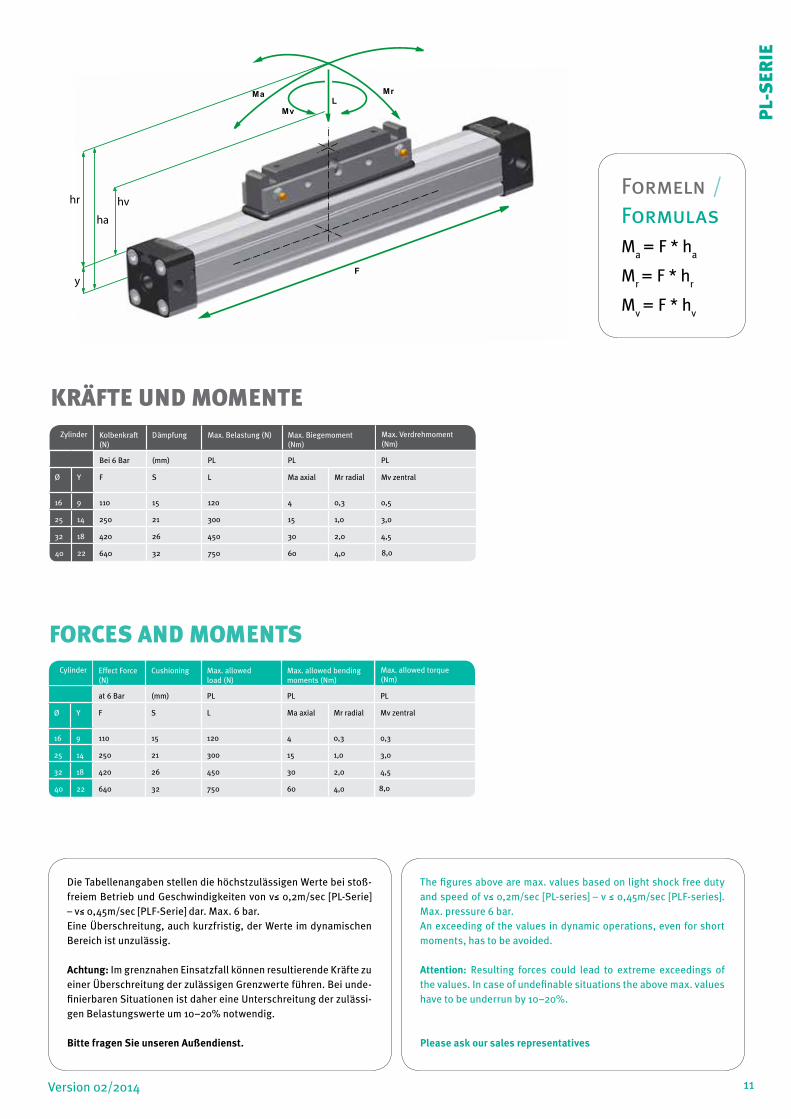
KRÄFTE UND MOMENTE
Die Tabellenangaben stellen die höchstzulässigen Werte bei stoß-freiem Betrieb und Geschwindigkeiten von v≤ 0,2m/sec [PL-Serie] – v≤ 0,45m/sec [PLF-Serie] dar. Max. 6 bar.Eine Überschreitung, auch kurzfristig, der Werte im dynamischen Bereich ist unzulässig.
Achtung: Im grenznahen Einsatzfall können resultierende Kräfte zu einer Überschreitung der zulässigen Grenzwerte führen. Bei unde-finierbaren Situationen ist daher eine Unterschreitung der zulässi-gen Belastungswerte um 10–20% notwendig.
Bitte fragen Sie unseren Außendienst.
The figures above are max. values based on light shock free duty and speed of v≤ 0,2m/sec [PL-series] – v ≤ 0,45m/sec [PLF-series]. Max. pressure 6 bar.An exceeding of the values in dynamic operations, even for short moments, has to be avoided.
Attention: Resulting forces could lead to extreme exceedings of the values. In case of undefinable situations the above max. values have to be underrun by 10–20%.
Please ask our sales representatives
Zylinder Kolbenkraft (N)
Dämpfung Max. Belastung (N) Max. Biegemoment (Nm)
Max. Verdrehmoment (Nm)
Bei 6 Bar (mm) PL PL PL
Ø Y F S L Ma axial Mr radial Mv zentral
16 9 110 15 120 4 0,3 0,5
25 14 250 21 300 15 1,0 3,0
32 18 420 26 450 30 2,0 4,5
40
640 32 750 60 4,0 8,022
Cylinder Effect Force (N)
Cushioning Max. allowed load (N)
Max. allowed bending moments (Nm)
Max. allowed torque (Nm)
at 6 Bar (mm) PL PL PL
Ø Y F S L Ma axial Mr radial Mv zentral
16 9 110 15 120 4 0,3 0,3
25 14 250 21 300 15 1,0 3,0
32 18 420 26 450 30 2,0 4,5
40
640 32 750 60 4,0 8,022
FORCES AND MOMENTS
PL-
SER
IE
Formeln / FormulasM
a = F * h
a
Mr = F * h
r
Mv = F * h
v

12
1500
2000
1000 2000 3000
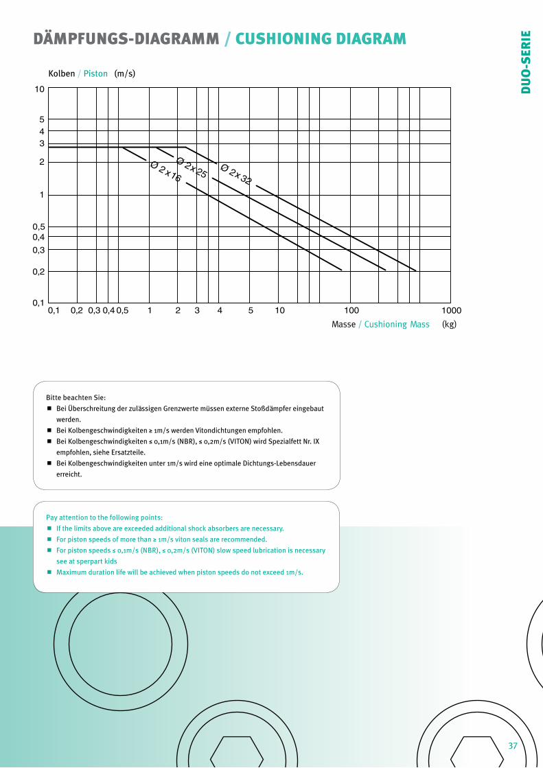
Bitte beachten Sie:
Bei Überschreitung der zulässigen Grenzwerte müssen externe Stoßdämpfer eingebaut
werden.
Bei Kolbengeschwindigkeiten ≥ 1m/s werden Vitondichtungen empfohlen.
Bei Kolbengeschwindigkeiten ≤ 0,1m/s (NBR), ≤ 0,2m/s (VITON) wird Spezialfett Nr. IX
empfohlen, siehe Ersatzteile.
Bei Kolbengeschwindigkeiten unter 1m/s wird eine optimale Lebensdauer erreicht.
Pay attention to the following points:
If the limits above are exceeded additional shock absorbers are necessary.
For piston speeds of more than ≥ 1m/s viton seals are recommended.
For piston speeds ≤ 0,1m/s (NBR), ≤ 0,2m/s (VITON) slow speed lubrication is necessary
see at sperpart kids
Maximum duration life will be achieved when piston speeds do not exceed 1m/s.
DÄMPFUNGS-DIAGRAMM / CUSHIONING DIAGRAM
W2+
W3
G
10
54
3
2
1
0,50,4
0,3
0,2
0,10,1 0,2 0,3 0,4 0,5 1 2 3 4 5 10 100 1000
Ø16
Ø25
Ø32
Ø40
Kolben
Masse / Cushioning Mass (kg)
Ma Ma
La
L
L
C C
B B
A A
L
LLr
LrMrMr
J H
G F
/ Piston (m/s)
12
PL-
SER
IE
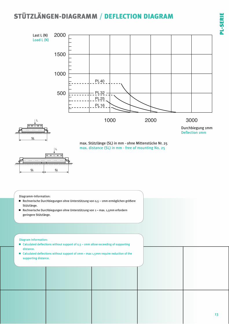
Diagramm-Information:
Rechnerische Durchbiegungen ohne Unterstützung von 0,5 – 1mm ermöglichen größere
Stützlänge.
Rechnerische Durchbiegungen ohne Unterstützung von 1 – max. 1,5mm erfordern
geringere Stützlänge.
Diagram Information:
Calculated deflections without support of 0,5 – 1mm allow exceeding of supporting
distance.
Calculated deflections without support of 1mm – max 1,5mm require reduction of the
supporting distance.
STÜTZLÄNGEN-DIAGRAMM / DEFLECTION DIAGRAM
500
1000
1500
2000
1000 2000 3000
PL16PL25PL32
PL40
L
SL
L
SL SL
Last L (N)Load L (N)
Durchbiegung 1mmDeflection 1mm
max. Stützlänge (SL) in mm - ohne Mittenstücke Nr. 25max. distance (SL) in mm - free of mounting No. 25
13
PL-
SER
IE
14 Version 02/2014
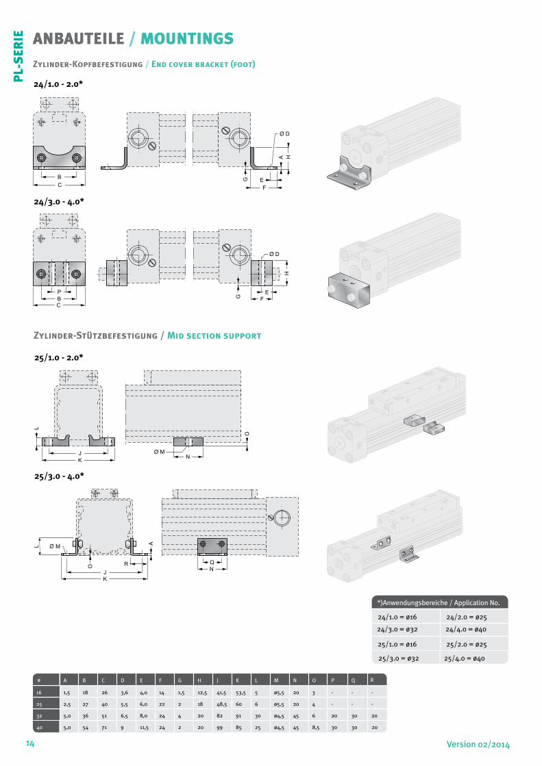
ANBAUTEILE / MOUNTINGS
Zylinder-Stützbefestigung / Mid section support
Zylinder-Kopfbefestigung / End cover bracket (foot)
ø A B C D E F G H J K L M N O P Q R
16 1,5 18 26 3,6 4,0 14 1,5 12,5 41,5 53,5 5 ø5,5 20 3 - - -
25 2,5 27 40 5,5 6,0 22 2 18 48,5 60 6 ø5,5 20 4 - - -
32 5,0 36 51 6,5 8,0 24 4 20 82 91 30 ø4,5 45 6 20 30 20
40 5,0 54 71 9 11,5 24 2 20 99 85 25 ø4,5 45 8,5 30 30 20
B
C
A
E
F
G
H
B
C
P
G
E
F
H
J
K
L
N
O
*)Anwendungsbereiche / Application No.
24/1.0 = ø16 24/2.0 = ø25
24/3.0 = ø32 24/4.0 = ø40
25/1.0 = ø16 25/2.0 = ø25
25/3.0 = ø32 25/4.0 = ø40
24/1.0 - 2.0*
24/3.0 - 4.0*
25/1.0 - 2.0*
25/3.0 - 4.0*
PL-
SER
IE
O
A
J
K
R Q
N
L M
15Version 02/2014
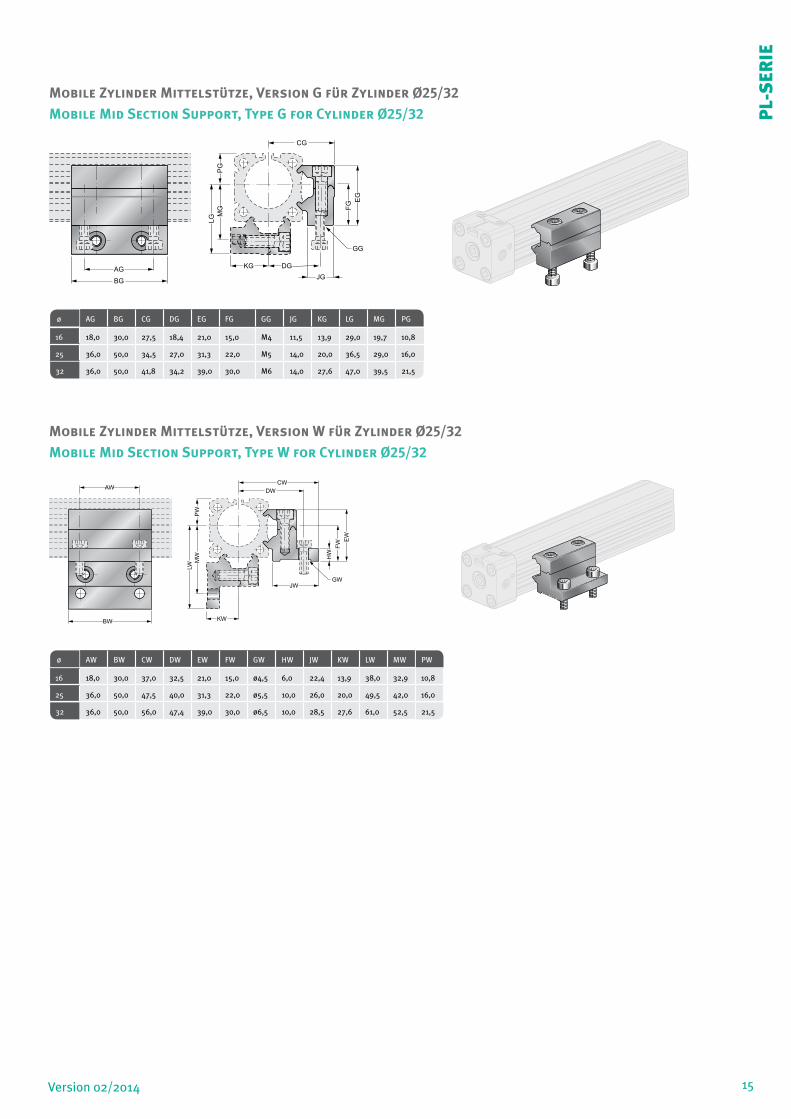
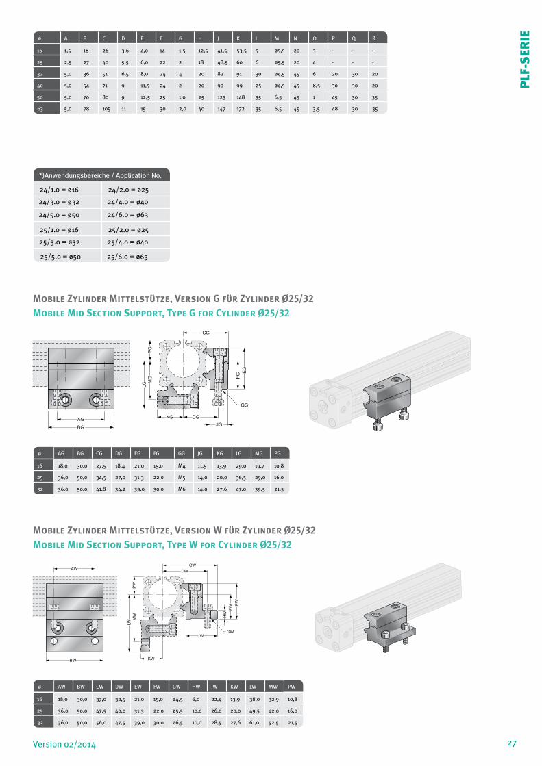
Mobile Zylinder Mittelstütze, Version W für Zylinder Ø25/32
ø AW BW CW DW EW FW GW HW JW KW LW MW PW
16 18,0 30,0 37,0 32,5 21,0 15,0 ø4,5 6,0 22,4 13,9 38,0 32,9 10,8
25 36,0 50,0 47,5 40,0 31,3 22,0 ø5,5 10,0 26,0 20,0 49,5 42,0 16,0
32 36,0 50,0 56,0 47,4 39,0 30,0 ø6,5 10,0 28,5 27,6 61,0 52,5 21,5
AG
EG
MG
PG
LG
FG
KG DG
JG
GG
CG
BG
AW
BW
EW
MW
PW
LW
FW
HW
KW
JW
GW
DW
CW
Mobile Zylinder Mittelstütze, Version G für Zylinder Ø25/32
Mobile Mid Section Support, Type G for Cylinder Ø25/32
Mobile Mid Section Support, Type W for Cylinder Ø25/32
ø AG BG CG DG EG FG GG JG KG LG MG PG
16 18,0 30,0 27,5 18,4 21,0 15,0 M4 11,5 13,9 29,0 19,7 10,8
25 36,0 50,0 34,5 27,0 31,3 22,0 M5 14,0 20,0 36,5 29,0 16,0
32 36,0 50,0 41,8 34,2 39,0 30,0 M6 14,0 27,6 47,0 39,5 21,5
PL-
SER
IE
16 Version 02/2014
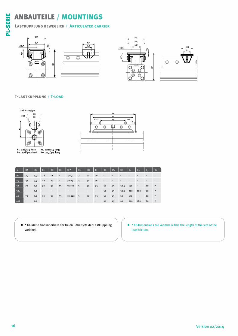
T-Lastkupplung / T-load
Lastkupplung beweglich / Articulated carrier
ø KA KB KC KD KE KF* KG KH KJ KK KS KT K1 K2 K3 K4
16 25 4,5 28 12 - 47-50 2 20 10 - - - - - - -
25 37 5,5 42 20 - 72-75 3 30 16 - - - - - - -
32 70 7,0 70 38 55 91-100 5 90 75 60 45 58,5 150 - 80 7
32L - 7,0 - - - - - - - 60 45 58,5 300 160 80 7
40 70 7,0 70 38 55 111-120 5 90 75 60 45 63 150 - 80 7
40L - 7,0 - - - - - - - 60 45 63 300 160 80 7
KC
KAKA KG
KD
KF
KHKJ
KK
K1
K2
K3K4 K4
226 + 227/3-4
Nr. 226/3-4 kurz No. 226/3-4 short
KB KS
KT
Nr. 227/3-4 langNo. 227/3-4 long
KC
KAKA KG
KD
KF
KHKJ
KK
K1
K2
K3K4 K4
226 + 227/3-4
Nr. 226/3-4 kurz No. 226/3-4 short
KB KS
KT
Nr. 227/3-4 langNo. 227/3-4 long
KG
KD
KF
KHKJ
K1
K2
K3K4 K4
Nr. 227/3-4 langNo. 227/3-4 long
KHKJ
KA
KC
∅KB
KD
KG
KF
KE
* KF-Maße sind innerhalb der freien Gabeltiefe der Lastkupplung
variabel.
* KF-Dimensions are variable within the length of the slot of the
load friction.
ANBAUTEILE / MOUNTINGSP
L-S
ERIE

17Version 02/2014
ZYLINDER / CYLINDER
Typen Ident.-Nr. Ausführungen Types Ident.-No. Description
PL 16/00PL 25/00PL 32/00PL 40/00
11.690. • • • •12.590. • • • •13.190. • • • •14.190. • • • •
Standard 00:v=1 m/sstarre LastkupplungNBR-DichtungenSchrauben 10.9 verzinkt3-dach Luftanschluss
PL 16/00PL 25/00PL 32/00PL 40/00
11.690. • • • •12.590. • • • •13.190. • • • •14.190. • • • •
Standard 00:v=1 m/sRegid load connectionNBR-sealsscrews 10.9 zinc plated3-air connections
PL 16/01PL 25/01PL 32/01PL 40/01
11.680. • • • •12.580. • • • •13.180. • • • •14.180. • • • •
Speziell 01:wie Standard 00, jedochSchrauben rostfrei
PL 16/01PL 25/01PL 32/01PL 40/01
11.680. • • • •12.580. • • • •13.180. • • • •14.180. • • • •
Special 01:as Standard 00, butscrews stainless steel
PL 16/02PL 25/02PL 32/02PL 40/02
11.670. • • • •12.570. • • • •13.170. • • • •14.170. • • • •
Speziell 02:wie Standard 00, jedochv=1 m/sViton-Dichtungen
PL 16/02PL 25/02PL 32/02PL 40/02
11.670. • • • •12.570. • • • •13.170. • • • •14.170. • • • •
Special 02:as Standard 00, butv=1 m/sViton-seals
PL 16/03PL 25/03PL 32/03PL 40/03
11.660. • • • •12.560. • • • •13.160. • • • •14.160. • • • •
Speziell 03:wie Standard 00, jedochv=1 m/sViton-DichtungenSchrauben rostfrei
PL 16/03PL 25/03PL 32/03PL 40/03
11.660. • • • •12.560. • • • •13.160. • • • •14.160. • • • •
Special 03:as Standard 00, butv=1 m/sViton-sealsscrews stainless steel
PL 32/05PL 40/05
13.195. • • • •14.195. • • • •
Speziell 05:wie Standard 00, jedochT-Lastkupplung kurz,mit 2 Anschlussbohrungen
PL 32/05PL 40/05
13.195. • • • •14.195. • • • •
Special 05:as Standard 00, butT-load connection short,with 2 connection bores
PL 32/09PL 40/09
13.199. • • • •14.199. • • • •
Speziell 09:wie Standard 00, jedochT-Lastkupplung lang,mit 4 Anschlussbohrungen
PL 32/09PL 40/09
13.199. • • • •14.199. • • • •
Special 09:as Standard 00, butT-load connection long,with 4 connection bores
PL 16/10PL 25/10PL 32/10PL 40/10
11.698. • • • •12.598. • • • •13.198. • • • •14.198. • • • •
Standard 10:langer Kolbenbei Senkrechtfahrt emp-fohlen
PL 16/10PL 25/10PL 32/10PL 40/10
11.698. • • • •12.598. • • • •13.198. • • • •14.198. • • • •
Standard 10:long pistonrecommended for vertical movement
Typen Ident.-Nr. Ausführungen Types Ident.-No. Description PL 16/20PL 25/20PL 32/20PL 40/20
11.692. • • • •12.592. • • • •13.192. • • • •14.192. • • • •
Standard 20:v=1 m/sbewegliche LastkupplungNBR-DichtungenSchrauben 10.9 verzinkt3-fach Luftanschluss
PL 16/20PL 25/20PL 32/20PL 40/20
11.692. • • • •12.592. • • • •13.192. • • • •14.192. • • • •
Standard 20:v=1 m/sflexible load connectionNBR-sealsscrews 10.9 zinc plated3-air connections
PL 16/22PL 25/22PL32/22PL 40/22
11.672. • • • •12.572. • • • •13.172. • • • •14.172. • • • •
Speziell 22:wie Standard 20,jedochv=1 M/SViton-Dichtungen
PL 16/22PL 25/22PL 32/22PL 40/22
11.672. • • • •12.572. • • • •13.172. • • • •14.172. • • • •
Special 22:flexible load connectionv=1 m/sVITON-seals
ø 16-40mm - PL 16-40/20-22
ø 16-40mm - PL 16-40/00-22
• • • • Stellenangaben bei Hubfestlegung ( 0100-5700 mm )• • • • Ident-figures for stroke definition ( 0100-5700 mm )
PL-
SER
IE
18 Version 02/2014
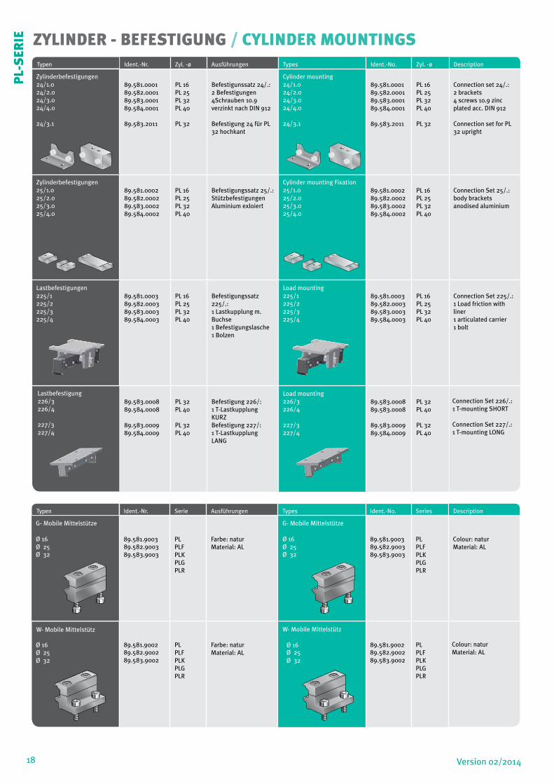
ZYLINDER - BEFESTIGUNG / CYLINDER MOUNTINGSTypen Ident.-Nr. Zyl. -ø Ausführungen Types Ident.-N0. Zyl. -ø Description
Zylinderbefestigungen 24/1.024/2.024/3.024/4.0
24/3.1
89.581.000189.582.000189.583.000189.584.0001
89.583.2011
PL 16PL 25PL 32PL 40
PL 32
Befestigunssatz 24/.:2 Befestigungen4Schrauben 10.9verzinkt nach DIN 912
Befestigung 24 für PL 32 hochkant
Cylinder mounting 24/1.0 24/2.024/3.0 24/4.0
24/3.1
89.581.000189.582.000189.583.000189.584.0001
89.583.2011
PL 16PL 25PL 32PL 40
PL 32
Connection set 24/.:2 brackets4 screws 10.9 zincplated acc. DIN 912
Connection set for PL 32 upright
Zylinderbefestigungen 25/1.025/2.025/3.025/4.0
89.581.000289.582.000289.583.000289.584.0002
PL 16PL 25PL 32PL 40
Befestigungssatz 25/.:StützbefestigungenAluminium exloiert
Cylinder mounting Fixation 25/1.025/2.025/3.025/4.0
89.581.000289.582.000289.583.000289.584.0002
PL 16PL 25PL 32PL 40
Connection Set 25/.:body bracketsanodised aluminium
Lastbefestigungen225/1225/2225/3225/4
89.581.000389.582.000389.583.000389.584.0003
PL 16PL 25PL 32PL 40
Befestigungssatz 225/.:1 Lastkupplung m. Buchse1 Befestigungslasche1 Bolzen
Load mounting225/1225/2225/3225/4
89.581.000389.582.000389.583.000389.584.0003
PL 16PL 25PL 32PL 40
Connection Set 225/.:1 Load friction with liner1 articulated carrier1 bolt
Lastbefestigung226/3226/4
227/3227/4
89.583.000889.584.0008
89.583.000989.584.0009
PL 32PL 40
PL 32PL 40
Befestigung 226/:1 T-Lastkupplung KURZBefestigung 227/:1 T-Lastkupplung LANG
Load mounting 226/3226/4
227/3227/4
89.583.000889.583.0008
89.583.000989.584.0009
PL 32PL 40
PL 32PL 40
Connection Set 226/.: 1 T-mounting SHORT
Connection Set 227/.: 1 T-mounting LONG
Typen Ident.-Nr. Serie Ausführungen Types Ident.-N0. Series Description
G- Mobile Mittelstütze
Ø 16 Ø 25 Ø 32
89.581.900389.582.900389.583.9003
PLPLFPLKPLGPLR
Farbe: naturMaterial: AL
G- Mobile Mittelstütze
Ø 16 Ø 25 Ø 32
89.581.900389.582.900389.583.9003
PLPLFPLKPLGPLR
Colour: naturMaterial: AL
W- Mobile Mittelstütz
Ø 16 Ø 25 Ø 32
89.581.900289.582.900289.583.9002
PLPLFPLKPLGPLR
Farbe: naturMaterial: AL
W- Mobile Mittelstütz Ø 16 Ø 25 Ø 32
89.581.900289.582.900289.583.9002
PLPLFPLKPLGPLR
Colour: natur Material: AL
PL-
SER
IE
19Version 02/2014
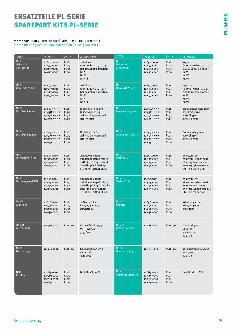
ERSATZTEILE PL-SERIESPAREPART KITS PL-SERIE
Typen Ident.-Nr. Zyl. -ø Ausführungen Types Ident.-No. Zyl. -ø Description
Nr. IUniversal– STANDARD
11.657.000012.557.000013.257.000014.057.0000
PL16PL25PL32PL40
2xKolben(alternativ Nr. 0, 1, 2, 3bei Bestellung angeben)Nr. VNr. VIINr. VIII
Nr. IUniversal– STANDARD
11.657.000012.557.000013.257.000014.057.0000
PL16PL25PL32PL40
2xpiston(alternative No. 0, 1, 2, 3please specify in order)Nr. VNr. VIINr. VIII
Nr. IIUniversal–VITON
11.657.000112.557.000113.357.000114.057.0001
PL16PL25PL32PL40
2XKolben(alternativ Nr. 0, 1, 2, 3bei Bestellung angeben)Nr. VINr. VIINr. VIII
Nr. IIUniversal–VITON
11.657.000112.557.000113.357.000114.057.0001
PL16PL25PL32PL40
2xpiston(alternative No. 0, 1, 2, 3please specify in order)Nr. VNr. VIINr. VIII
Nr. IIIDichtband innen
11.658.• • • •12.558.• • • •13.258.• • • •14.058.• • • •
PL16PL25PL32PL40
Dichtband inklusiveJustiervernietungauf Hublänge passendgeschnitten
Nr. IIIInner sealing band
11.658.• • • •12.558.• • • •13.258.• • • •14.058.• • • •
PL16PL25PL32PL40
sealing band includingadjustment rivetaccording tostroke length
Nr. IVDichtband außen
11.659.• • • •12.559.• • • • 13.259.• • • •14.059.• • • •
PL16PL25PL32PL40
Dichtband außenauf Hublänge passendgeschnitten
Nr. IVOuter sealing band
11.659.• • • •12.559.• • • •13.259.• • • •14.059.• • • •
PL16PL25PL32PL40
Outer sealing bandaccording tostroke length
Nr. VDichtungen–NBR
11.655.000012.555.000013.255.000014.055.0000
PL16PL25PL32PL40
2xKolbendichtung2xKolbendämpfdichtung2xO-Ring-Dämpfschraube2xO-Ring-Zylinderkopf1xO-Ring-Lastkupplung
Nr. VSeals NBR
11.655.000012.555.000013.255.000014.055.0000
PL16PL25PL32PL40
2Xpiston seal2Xpiston cushion seal2Xo-ring cushion seal2Xo-ring cylinder end cap1Xo-ring connection
Nr. VIDichtungen–VITON
11.655.000112.555.000113.255.000114.055.0001
PL16PL25PL32PL40
2xKolbendichtung2xKolbendämpfdichtung2xO-Ring-Dämpfschraube2xO-Ring-Zylinderkopf1xO-Ring-Lastkupplung
Nr. VISeals VITON
11.655.000112.555.000113.255.000114.055.0001
PL16PL25PL32PL40
2Xpiston seal2Xpiston cushion seal2Xo-ring cushion seal2Xo-ring cylinder end cap1Xo-ring connection
Nr. VIIGleitteile
11.656.000012.556.000013.256.000014.056.0000
PL16PL25PL32PL40
2xGleitstückeNr. 1, 2, 3 oder 42xAbstreifer
Nr. VIISlidings
11.656.000012.556.000013.256.000014.056.0000
PL16PL25PL32PL40
2xbearing stripNo. 1, 2, 3 oder 42xscraper
Nr. VIIIFettpackung
12.589.0000 PL16–40 Normalfett SL32/30V > =0,1m/s30g-Dose
Nr. VIIIGrease package
12.589.0000 PL16–40 standard grease SL32/30v > =0,1m/s30gr. tin
Nr. IXFettpackung
12.589.0001 PL16–40 Spezialfett LL33/30v < 0,1m/s30g-Dose
Nr. IXGrease package
12.589.0001 PL16–40 special grease LL33/30v < 0,1m/s30gr. tin
Nr.XKombisatz
11.689.000212.589.000213.289.000214.089.0002
PL16PL25PL32PL40
Nr.V, Nr. VII, Nr. VIII Nr. XCombiset Standard
11.689.000212.589.000213.289.000214.089.0002
PL16PL25PL32PL40
Nr.V, Nr. VII, Nr. VIII
• • • • Stellenangaben bei Hubfestlegung ( 0100-5700 mm )• • • • Ident-figures for stroke definition ( 0100-5700 mm )
PL-
SER
IE
20 Version 02/2014
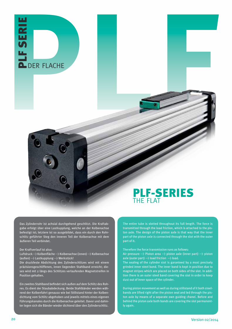
PLFPLF
SER
IE
DER FLACHE
PLF-SERIESTHE FLAT
Das Zylinderrohr ist achsial durchgehend geschlitzt. Die Kraftab-gabe erfolgt über eine Lastkupplung, welche an der Kolbenachse befestigt ist; letztere ist so ausgebildet, dass ein durch den Rohr-schlitz geführter Steg den inneren Teil der Kolbenachse mit dem äußeren Teil verbindet.
Der Kraftverlauf ist also:Luftdruck > Kolbenfläche > Kolbenachse (innen) > Kolbenachse (außen) > Lastkupplung > Werkstück!Die druckfeste Abdichtung des Zylinderschlitzes wird mit einem präzisionsgeschliffenen, innen liegenden Stahlband erreicht; die-ses wird mit 2 längs des Schlitzes verlaufenden Magnetstreifen in Position gehalten.
Ein zweites Stahlband befindet sich außen auf dem Schlitz des Roh-res. Es dient der Staubabdeckung. Beide Stahlbänder werden wäh-rend der Kolbenfahrt genauso wie bei Stillstand hinter der Kolben-dichtung vom Schlitz abgehoben und jeweils mittels eines eigenen Führungskanales durch die Kolbenachse geleitet. Davor und dahin-ter legen sich die Bänder wieder dichtend über den Zylinderschlitz.
The entire tube is slotted throughout its full length. The force is transmitted through the load friction, which is attached to the pis-ton axle. The design of the piston axle is that way that the inner part of the piston axle is connected through the slot with the outer part of it.
Therefore the force transmission runs as follows:Air pressure > Piston area > piston axle (inner part) > piston axle (outer part) > load friction > load.The sealing of the cylinder slot is garanteed by a most precisely grinded inner steel band. The inner band is kept in position due to magnet stripes which are placed on both sides of the slot. In addi-tion there is an outer steel band covering the slot in order to keep dust out of inner space of the cylinder.
During piston movement as well as during stillstand of it both steel-bands are lifted right after the piston seal and led through the pis-ton axle by means of a separate own guiding chanel. Before and behind the piston axle both bands are covering the slot permanent-ly again.

21Version 02/2014
TECHNISCHE DATEN / TECHNICAL DATA
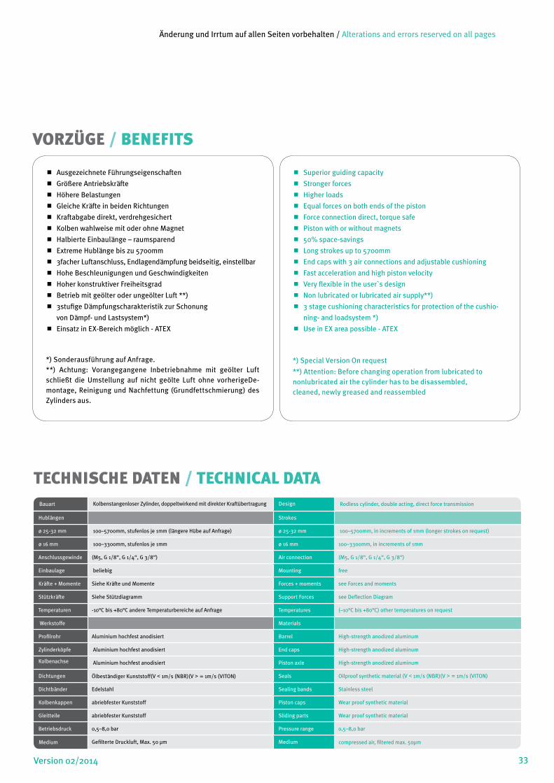
Gleiche Kräfte in beiden Richtungen
Kraftabgabe direkt, verdrehgesichert
Kolben wahlweise mit oder ohne Magnet
Halbierte Einbaulänge – raumsparend
Extreme Hublänge > 5700mm
3facher Luftanschluss, Endlagendämpfung beidseitig, einstell-
bar
Hohe Beschleunigungen und Geschwindigkeiten
Hoher konstruktiver Freiheitsgrad
Betrieb mit geölter oder ungeölter Luft **)
3stufige Dämpfungscharakteristik zur Schonung
von Dämpf- und Lastsystem*)
Einsatz in EX-Bereich möglich - ATEX
*) Sonderausführung auf Anfrage.**) Achtung: Vorangegangene Inbetriebnahme mit geölter Luft schließt die Umstellung auf nicht geölte Luft ohne vorherigeDe-montage, Reinigung und Nachfettung (Grundfettschmierung) des Zylinders aus.
Equal forces on both ends of the piston
Force connection direct, torque safe
Piston with or without magnets
50% space-savings
Long strokes up to > 5700mm
End caps with 3 air connections and adjustable cushioning
Fast acceleration and high piston velocity
Very flexible in the user`s design
Non lubricated or lubricated air supply**)
3 stage cushioning characteristics for protection of the cushio-
ning- and loadsystem *)
Use in EX area possible - ATEX
*) Special Version On request
**) Attention: Before changing operation from lubricated tononlubricated air the cylinder has to be disassembled,cleaned, newly greased and reassembled
VORZÜGE / BENEFITS
Bauart
Kolbenstangenloser Zylinder, doppeltwirkend mit direkter Kraftübertragung Design Rodless cylinder, double acting, direct force transmission
Hublängen Strokes
ø 25-63 mm 100–5700mm, stufenlos je 1mm (längere Hübe auf Anfrage) ø 25-63 mm 100–5700mm, in increments of 1mm (longer strokes on request)
ø 16 mm 100–4400mm, stufenlos je 1mm ø 16 mm 100–4400mm, in increments of 1mm
Anschlussgewinde (M5, G 1/8“, G 1/4“, g3/8“) Air connection (M5, G 1/8“, G 1/4“, g3/8“)
Einbaulage beliebig Mounting free
Kräfte + Momente Siehe Kräfte und Momente Forces + moments see Forces and moments
Stützkräfte Siehe Stützdiagramm Support Forces see Deflection Diagram
Temperaturen -10°C bis +80°C andere Temperaturbereiche auf Anfrage Temperatures (–10°C bis +80°C) other temperatures on request
Werkstoffe Materials
Profilrohr Aluminium hochfest anodisiert Barrel High-strength anodized aluminum
Zylinderköpfe Aluminium hochfest anodisiert End caps High-strength anodized aluminum
Kolbenachse Aluminium hochfest anodisiert Piston axle High-strength anodized aluminum
Dichtungen Ölbeständiger Kunststoff(V < 1m/s (NBR)(V > = 1m/s (VITON) Seals Oilproof synthetic material (V < 1m/s (NBR)(V > = 1m/s (VITON)
Dichtbänder Edelstahl Sealing bands Stainless steel
Kolbenkappen abriebfester Kunststoff Piston caps Wear proof synthetic material
Gleitteile abriebfester Kunststoff Sliding parts Wear proof synthetic material
Betriebsdruck 0,5–8,0 bar Pressure range 0,5–8,0 bar
Medium Gefilterte Druckluft, Max. 50 µm Medium compressed air, filtered max. 50µm
Änderung und Irrtum auf allen Seiten vorbehalten / Alterations and errors reserved on all pages
22 Version 02/2014
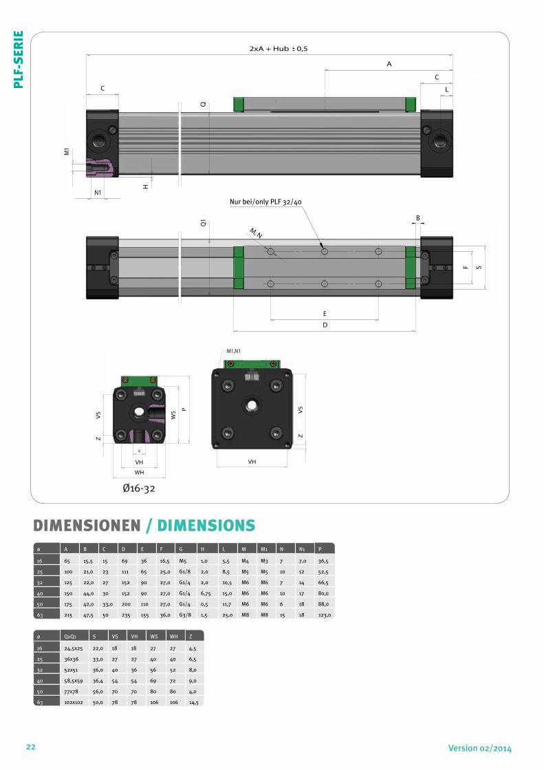
DIMENSIONEN / DIMENSIONSø A B C D E F G H L M M1 N N1 P
16 65 15,5 15 69 36 16,5 M5 1,0 5,5 M4 M3 7 7,0 36,5
25 100 21,0 23 111 65 25,0 G1/8 2,0 8,5 M5 M5 10 12 52,5
32 125 22,0 27 152 90 27,0 G1/4 2,0 10,5 M6 M6 7 14 66,5
40 150 44,0 30 152 90 27,0 G1/4 6,75 15,0 M6 M6 10 17 80,0
50 175 42,0 33,0 200 110 27,0 G1/4 0,5 11,7 M6 M6 6 18 88,0
63 215 47,5 50 235 155 36,0 G3/8 1,5 25,0 M8 M8 15 18 123,0
ø QxQ1 S VS VH WS WH Z
16 24,5x25 22,0 18 18 27 27 4,5
25 36x36 33,0 27 27 40 40 6,5
32 52x51 36,0 40 36 56 52 8,0
40 58,5x59 36,4 54 54 69 72 9,0
50 77x78 56,0 70 70 80 80 4,0
63 102x102 50,0 78 78 106 106 14,5
A
S
D
C
M, N
QWH
VS
Z
VHVH
L
N1
C
H
2xA + Hub 0,5
M1
Q1
G
E
F
B
A
S
D
C
WH
WS P
VS
Z
VS
Z
VHVH
M1,N1
L
G
F
B
PLF
-SER
IE
Nur bei/only PLF 32/40
Ø16-32
23Version 02/2014
L
Mv
Ma
Mr
F
ha
y
hrhv
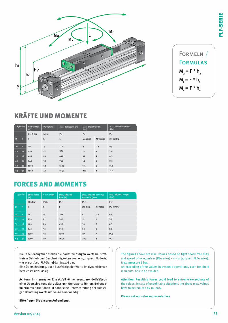
Die Tabellenangaben stellen die höchstzulässigen Werte bei stoß-freiem Betrieb und Geschwindigkeiten von v≤ 0,2m/sec [PL-Serie] – v≤ 0,45m/sec [PLF-Serie] dar. Max. 6 bar.Eine Überschreitung, auch kurzfristig, der Werte im dynamisierten Bereich ist unzulässig.
Achtung: Im grenznahen Einsatzfall können resultierende Kräfte zu einer Überschreitung der zulässigen Grenzwerte führen. Bei unde-finierbaren Situationen ist daher eine Unterschreitung der zulässi-gen Belastungswerte um 10–20% notwendig.
Bitte fragen Sie unseren Außendienst.
The figures above are max. values based on light shock free duty and speed of v≤ 0,2m/sec [PL-series] – v ≤ 0,45m/sec [PLF-series]. Max. pressure 6 bar.An exceeding of the values in dynamic operations, even for short moments, has to be avoided.
Attention: Resulting forces could lead to extreme exceedings of the values. In case of undefinable situations the above max. values have to be reduced by 10–20%.
Please ask our sales representatives
KRÄFTE UND MOMENTE Zylinder Kolbenkraft
(N)Dämpfung Max. Belastung (N) Max. Biegemoment
(Nm) Max. Verdrehmoment (Nm)
Bei 6 Bar (mm) PLF PLF PLF
Ø Y F S L Ma axial Mr radial Mv zentral
16 9 110 15 120 4 0,3 0,5
25 14 250 21 300 15 1 3,0
32 18 420 26 450 30 2 4,5
40 22 640 32 750 60 4 8,0
50 28 1000 32 1200 115 7 15,0
63
1550 40 1650 200 8 24,036
Cylinder Effect Force (N)
Cushioning Max. allowed load (N)
Max. allowed bending moments (Nm)
Max. allowed torque (Nm)
at 6 Bar (mm) PLF PLF PLF
Ø Y F S L Ma axial Mr radial Mv zentral
16 9 110 15 120 4 0,3 0,5
25 14 250 21 300 15 1 3,0
32 18 420 26 450 30 2 4,5
40 22 640 32 750 60 4 8,0
50 28 1000 32 1200 115 7 15,0
63
1550 40 1650 200 8 24,036
FORCES AND MOMENTS
PLF
-SER
IE
Formeln / FormulasM
a = F * h
a
Mr = F * h
r
Mv = F * h
v
24
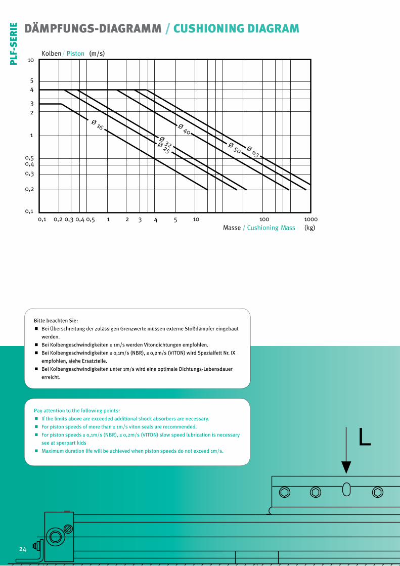
DÄMPFUNGS-DIAGRAMM / CUSHIONING DIAGRAM
10
54
3
2
1
0,50,4
0,3
0,2
0,10,1 0,2 0,3 0,4 0,5 1 2 3 4 5 10 100 1000
Ø 16
Ø 25
Ø 32
Ø 40
Ø 50 Ø 63
Kolben
Masse
/ Piston (m/s)
L
Bitte beachten Sie:
Bei Überschreitung der zulässigen Grenzwerte müssen externe Stoßdämpfer eingebaut
werden.
Bei Kolbengeschwindigkeiten ≥ 1m/s werden Vitondichtungen empfohlen.
Bei Kolbengeschwindigkeiten ≤ 0,1m/s (NBR), ≤ 0,2m/s (VITON) wird Spezialfett Nr. IX
empfohlen, siehe Ersatzteile.
Bei Kolbengeschwindigkeiten unter 1m/s wird eine optimale Dichtungs-Lebensdauer
erreicht.
Pay attention to the following points:
If the limits above are exceeded additional shock absorbers are necessary.
For piston speeds of more than ≥ 1m/s viton seals are recommended.
For piston speeds ≤ 0,1m/s (NBR), ≤ 0,2m/s (VITON) slow speed lubrication is necessary
see at sperpart kids
Maximum duration life will be achieved when piston speeds do not exceed 1m/s.
G
10
54
3
2
1
0,50,4
0,3
0,2
0,10,1 0,2 0,3 0,4 0,5 1 2 3 4 5 10 100 1000
Ø16
Ø25
Ø32
Ø40
Kolben
Masse / Cushioning Mass (kg)
Ma Ma
La
L
L
C C
B B
A A
L
LLr
LrMrMr
J H
G F
24
PLF
-SER
IE

Diagramm-Information:
Rechnerische Durchbiegungen ohne Unterstützung von 0,5 – 1mm ermöglichen größere
Stützlänge.
Rechnerische Durchbiegungen ohne Unterstützung von > 1 – max. 1,5mm erfordern
geringere Stützlänge.
Diagram Information:
Calculated deflections without support of 0,5 – 1mm allow exceeding of supporting
distance.
Calculated deflections without support of 1mm – max 1,5mm require reduction of the
supporting distance.
500
1000
1500
2000
1000 2000 3000
PLF16PLF25PLF32
PLF40
PLF50
PLF63
L
SL
L
SL SL
STÜTZLÄNGEN-DIAGRAMM / DEFLECTION DIAGRAM
Last L (N)Load L (N)
Durchbiegung 1mmDeflection 1mm
max. Stützlänge (SL) in mm - ohne Mittenstücke Nr. 25max. distance (SL) in mm - free of mounting No. 25
25
PLF
-SER
IE
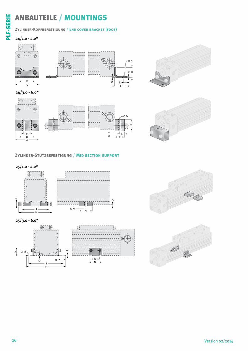
26 Version 02/2014
ANBAUTEILE / MOUNTINGS
Zylinder-Stützbefestigung / Mid section support
Zylinder-Kopfbefestigung / End cover bracket (foot)
B
C
A
E
F
G
H
B
C
P
G
E
F
H
J
K
L
N
O
24/1.0 - 2.0*
25/1.0 - 2.0*
24/3.0 - 6.0*
25/3.0 - 6.0*
O
A
J
K
R Q
N
L M
PLF
-SER
IE
27Version 02/2014
ø A B C D E F G H J K L M N O P Q R
16 1,5 18 26 3,6 4,0 14 1,5 12,5 41,5 53,5 5 ø5,5 20 3 - - -
25 2,5 27 40 5,5 6,0 22 2 18 48,5 60 6 ø5,5 20 4 - - -
32 5,0 36 51 6,5 8,0 24 4 20 82 91 30 ø4,5 45 6 20 30 20
40 5,0 54 71 9 11,5 24 2 20 90 99 25 ø4,5 45 8,5 30 30 20
50 5,0 70 80 9 12,5 25 1,0 25 123 148 35 6,5 45 1 45 30 35
63 5,0 78 105 11 15 30 2,0 40 147 172 35 6,5 45 3,5 48 30 35
Mobile Zylinder Mittelstütze, Version W für Zylinder Ø25/32
ø AW BW CW DW EW FW GW HW JW KW LW MW PW
16 18,0 30,0 37,0 32,5 21,0 15,0 ø4,5 6,0 22,4 13,9 38,0 32,9 10,8
25 36,0 50,0 47,5 40,0 31,3 22,0 ø5,5 10,0 26,0 20,0 49,5 42,0 16,0
32 36,0 50,0 56,0 47,5 39,0 30,0 ø6,5 10,0 28,5 27,6 61,0 52,5 21,5
AG
EG
MG
PG
LG
FG
KG DG
JG
GG
CG
BG
AW
BW
EW
MW
PW
LW
FW
HW
KW
JW
GW
DW
CW
Mobile Zylinder Mittelstütze, Version G für Zylinder Ø25/32
Mobile Mid Section Support, Type G for Cylinder Ø25/32
Mobile Mid Section Support, Type W for Cylinder Ø25/32
ø AG BG CG DG EG FG GG JG KG LG MG PG
16 18,0 30,0 27,5 18,4 21,0 15,0 M4 11,5 13,9 29,0 19,7 10,8
25 36,0 50,0 34,5 27,0 31,3 22,0 M5 14,0 20,0 36,5 29,0 16,0
32 36,0 50,0 41,8 34,2 39,0 30,0 M6 14,0 27,6 47,0 39,5 21,5
*)Anwendungsbereiche / Application No.
24/1.0 = ø16 24/2.0 = ø25
24/3.0 = ø32 24/4.0 = ø40
24/5.0 = ø50 24/6.0 = ø63
25/1.0 = ø16 25/2.0 = ø25
25/3.0 = ø32 25/4.0 = ø40
25/5.0 = ø50 25/6.0 = ø63
PLF
-SER
IE
28 Version 02/2014
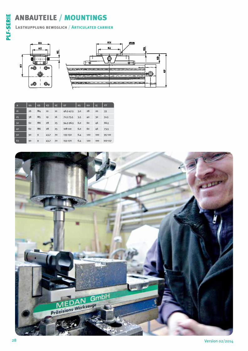
Lastkupplung beweglich / Articulated carrier
ANBAUTEILE / MOUNTINGS
ø KA KB KD KE KF KG KH KJ KY
16 26 M4 10 10 46,5-47,5 3,0 28 20 33
25 38 M5 19 16 71,5-73,5 3,5 40 30 51,5
32 62 M6 28 25 94,5-96,5 6,0 60 46 66,5
40 62 M6 28 25 108-110 6,0 60 46 73,5
50 90 9 43,7 70 135-150 6,4 120 100 95-110
63 90 9 43,7 70 155-170 6,4 120 100 102-117
KA
KE
KY
KC
KH
KJ
KB
KG
KD
KF
ZJ
ZK
ZF
ZN
ZQ
ZA ZG
ZDZH
ZE
ZF
PLF
-SER
IE
29Version 02/2014
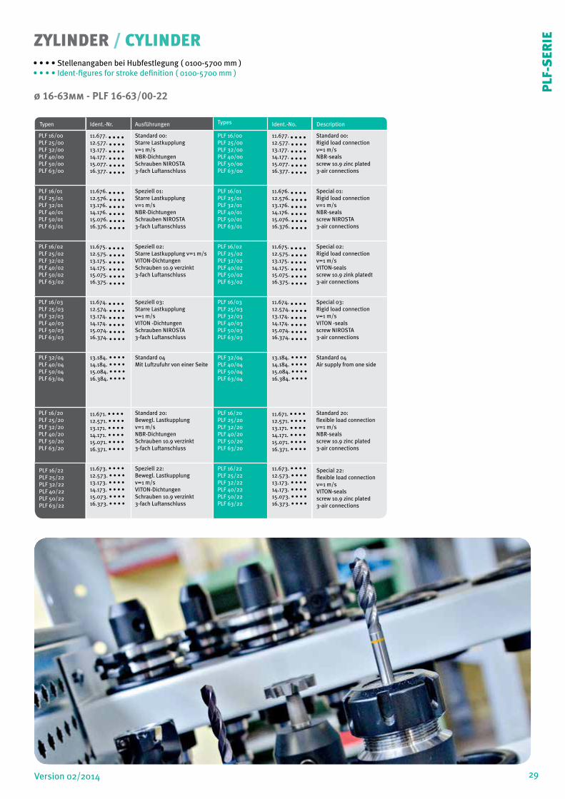
ZYLINDER / CYLINDER
Typen Ident.-Nr. Ausführungen Types Ident.-No. Description
PLF 16/00PLF 25/00PLF 32/00PLF 40/00PLF 50/00PLF 63/00
11.677. • • • •12.577. • • • •13.177. • • • •14.177. • • • •15.077. • • • •16.377. • • • •
Standard 00:Starre Lastkupplungv=1 m/sNBR-DichtungenSchrauben NIROSTA3-fach Luftanschluss
PLF 16/00PLF 25/00PLF 32/00PLF 40/00PLF 50/00PLF 63/00
11.677. • • • •12.577. • • • •13.177. • • • •14.177. • • • •15.077. • • • •16.377. • • • •
Standard 00:Rigid load connectionv=1 m/sNBR-sealsscrew 10.9 zinc plated3-air connections
PLF 16/01PLF 25/01PLF 32/01PLF 40/01PLF 50/01PLF 63/01
11.676. • • • •12.576. • • • •13.176. • • • •14.176. • • • •15.076. • • • •16.376. • • • •
Speziell 01:Starre Lastkupplungv=1 m/sNBR-DichtungenSchrauben NIROSTA3-fach Luftanschluss
PLF 16/01PLF 25/01PLF 32/01PLF 40/01PLF 50/01PLF 63/01
11.676. • • • •12.576. • • • •13.176. • • • •14.176. • • • •15.076. • • • •16.376. • • • •
Special 01:Rigid load connectionv=1 m/sNBR-sealsscrew NIROSTA3-air connections
PLF 16/02PLF 25/02PLF 32/02PLF 40/02PLF 50/02PLF 63/02
11.675. • • • •12.575. • • • •13.175. • • • •14.175. • • • •15.075. • • • •16.375. • • • •
Speziell 02:Starre Lastkupplung v=1 m/sVITON-DichtungenSchrauben 10.9 verzinkt3-fach Luftanschluss
PLF 16/02PLF 25/02PLF 32/02PLF 40/02PLF 50/02PLF 63/02
11.675. • • • •12.575. • • • •13.175. • • • •14.175. • • • •15.075. • • • •16.375. • • • •
Special 02:Rigid load connectionv=1 m/sVITON-sealsscrew 10.9 zink platedt3-air connections
PLF 16/03PLF 25/03PLF 32/03PLF 40/03PLF 50/03PLF 63/03
11.674. • • • •12.574. • • • •13.174. • • • •14.174. • • • •15.074. • • • •16.374. • • • •
Speziell 03:Starre Lastkupplungv=1 m/sVITON -DichtungenSchrauben NIROSTA3-fach Luftanschluss
PLF 16/03PLF 25/03PLF 32/03PLF 40/03PLF 50/03PLF 63/03
11.674. • • • •12.574. • • • •13.174. • • • •14.174. • • • •15.074. • • • •16.374. • • • •
Special 03:Rigid load connectionv=1 m/sVITON -sealsscrew NIROSTA3-air connections
PLF 32/04PLF 40/04PLF 50/04PLF 63/04
13.184. • • • •14.184. • • • •15.084. • • • •16.384. • • • •
Standard 04Mit Luftzufuhr von einer Seite
PLF 32/04PLF 40/04PLF 50/04PLF 63/04
13.184. • • • •14.184. • • • •15.084. • • • •16.384. • • • •
Standard 04Air supply from one side
PLF 16/20PLF 25/20PLF 32/20PLF 40/20PLF 50/20PLF 63/20
11.671. • • • •12.571. • • • •13.171. • • • •14.171. • • • •15.071. • • • •16.371. • • • •
Standard 20:Bewegl. Lastkupplungv=1 m/sNBR-DichtungenSchrauben 10.9 verzinkt3-fach Luftanschluss
PLF 16/20PLF 25/20PLF 32/20PLF 40/20PLF 50/20PLF 63/20
11.671. • • • •12.571. • • • •13.171. • • • •14.171. • • • •15.071. • • • •16.371. • • • •
Standard 20:flexible load connectionv=1 m/sNBR-sealsscrew 10.9 zinc plated3-air connections
PLF 16/22PLF 25/22PLF 32/22PLF 40/22PLF 50/22PLF 63/22
11.673. • • • •12.573. • • • •13.173. • • • •14.173. • • • •15.073. • • • •16.373. • • • •
Speziell 22:Bewegl. Lastkupplungv=1 m/sVITON-DichtungenSchrauben 10.9 verzinkt3-fach Luftanschluss
PLF 16/22PLF 25/22PLF 32/22PLF 40/22PLF 50/22PLF 63/22
11.673. • • • •12.573. • • • •13.173. • • • •14.173. • • • •15.073. • • • •16.373. • • • •
Special 22:flexible load connectionv=1 m/sVITON-sealsscrew 10.9 zinc plated3-air connections
ø 16-63mm - PLF 16-63/00-22
• • • • Stellenangaben bei Hubfestlegung ( 0100-5700 mm )• • • • Ident-figures for stroke definition ( 0100-5700 mm )
PLF
-SER
IE
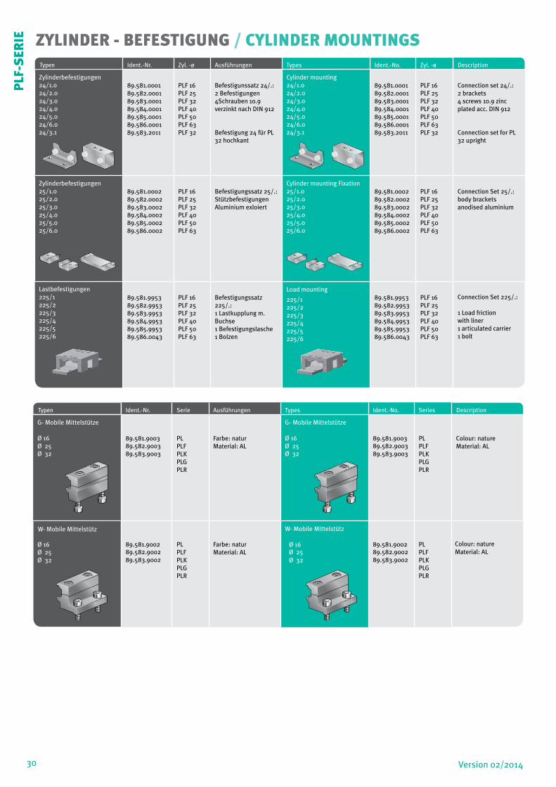
30 Version 02/2014
ZYLINDER - BEFESTIGUNG / CYLINDER MOUNTINGSTypen Ident.-Nr. Zyl. -ø Ausführungen Types Ident.-No. Zyl. -ø Description
Zylinderbefestigungen 24/1.024/2.024/3.024/4.024/5.024/6.024/3.1
89.581.000189.582.000189.583.000189.584.000189.585.000189.586.000189.583.2011
PLF 16PLF 25PLF 32PLF 40PLF 50PLF 63PLF 32
Befestigunssatz 24/.:2 Befestigungen4Schrauben 10.9verzinkt nach DIN 912
Befestigung 24 für PL 32 hochkant
Cylinder mounting 24/1.024/2.024/3.024/4.024/5.024/6.024/3.1
89.581.000189.582.000189.583.000189.584.000189.585.000189.586.000189.583.2011
PLF 16PLF 25PLF 32PLF 40PLF 50PLF 63PLF 32
Connection set 24/.:2 brackets4 screws 10.9 zincplated acc. DIN 912
Connection set for PL 32 upright
Zylinderbefestigungen 25/1.025/2.025/3.025/4.025/5.025/6.0
89.581.000289.582.000289.583.000289.584.000289.585.000289.586.0002
PLF 16PLF 25PLF 32PLF 40PLF 50PLF 63
Befestigungssatz 25/.:StützbefestigungenAluminium exloiert
Cylinder mounting Fixation 25/1.025/2.025/3.025/4.025/5.025/6.0
89.581.000289.582.000289.583.000289.584.000289.585.000289.586.0002
PLF 16PLF 25PLF 32PLF 40PLF 50PLF 63
Connection Set 25/.:body bracketsanodised aluminium
Lastbefestigungen225/1225/2225/3225/4225/5225/6
89.581.995389.582.995389.583.995389.584.995389.585.995389.586.0043
PLF 16PLF 25PLF 32PLF 40PLF 50PLF 63
Befestigungssatz 225/.:1 Lastkupplung m. Buchse1 Befestigungslasche1 Bolzen
Load mounting
225/1225/2225/3225/4225/5225/6
89.581.995389.582.995389.583.995389.584.995389.585.995389.586.0043
PLF 16PLF 25PLF 32PLF 40PLF 50PLF 63
Connection Set 225/.:
1 Load frictionwith liner1 articulated carrier1 bolt
Typen Ident.-Nr. Serie Ausführungen Types Ident.-N0. Series Description
G- Mobile Mittelstütze
Ø 16 Ø 25 Ø 32
89.581.900389.582.900389.583.9003
PLPLFPLKPLGPLR
Farbe: naturMaterial: AL
G- Mobile Mittelstütze
Ø 16 Ø 25 Ø 32
89.581.900389.582.900389.583.9003
PLPLFPLKPLGPLR
Colour: natureMaterial: AL
W- Mobile Mittelstütz
Ø 16 Ø 25 Ø 32
89.581.900289.582.900289.583.9002
PLPLFPLKPLGPLR
Farbe: naturMaterial: AL
W- Mobile Mittelstütz Ø 16 Ø 25 Ø 32
89.581.900289.582.900289.583.9002
PLPLFPLKPLGPLR
Colour: nature Material: AL
PLF
-SER
IE
31Version 02/2014
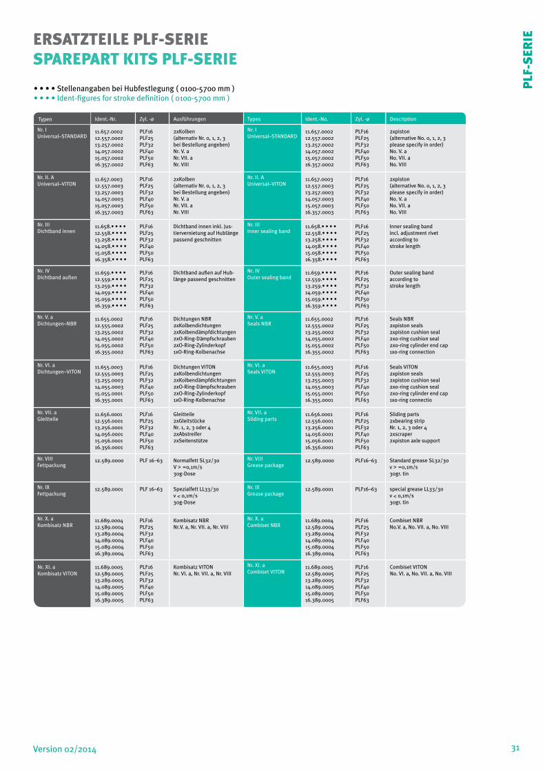
ERSATZTEILE PLF-SERIESPAREPART KITS PLF-SERIE
Typen Ident.-Nr. Zyl. -ø Ausführungen Types Ident.-No. Zyl. -ø Description
Nr. IUniversal–STANDARD
11.657.000212.557.000213.257.000214.057.000215.057.000216.357.0002
PLF16PLF25PLF32PLF40PLF50PLF63
2xKolben(alternativ Nr. 0, 1, 2, 3bei Bestellung angeben)Nr. V. aNr. VII. aNr. VIII
Nr. IUniversal–STANDARD
11.657.000212.557.000213.257.000214.057.000215.057.000216.357.0002
PLF16PLF25PLF32PLF40PLF50PLF63
2xpiston(alternative No. 0, 1, 2, 3please specify in order)No. V. aNo. VII. aNo. VIII
Nr. II. A Universal–VITON
11.657.000312.557.000313.257.000314.057.000315.057.000316.357.0003
PLF16PLF25PLF32PLF40PLF50PLF63
2xKolben(alternativ Nr. 0, 1, 2, 3bei Bestellung angeben)Nr. V. aNr. VII. aNr. VIII
Nr. II. A Universal–VITON
11.657.000312.557.000313.257.000314.057.000315.057.000316.357.0003
PLF16PLF25PLF32PLF40PLF50PLF63
2xpiston(alternative No. 0, 1, 2, 3please specify in order)No. V. aNo. VII. aNo. VIII
Nr. IIIDichtband innen
11.658.• • • •12.558.• • • •13.258.• • • •14.058.• • • •15.058.• • • •16.358.• • • •
PLF16PLF25PLF32PLF40PLF50PLF63
Dichtband innen inkl. Jus-tiervernietung auf Hublänge passend geschnitten
Nr. IIIInner sealing band
11.658.• • • •12.558.• • • •13.258.• • • •14.058.• • • •15.058.• • • •16.358.• • • •
PLF16PLF25PLF32PLF40PLF50PLF63
Inner sealing bandincl. adjustment rivetaccording tostroke length
Nr. IVDichtband außen
11.659.• • • •12.559.• • • •13.259.• • • •14.059.• • • •15.059.• • • •16.359.• • • •
PLF16PLF25PLF32PLF40PLF50PLF63
Dichtband außen auf Hub-länge passend geschnitten
Nr. IVOuter sealing band
11.659.• • • •12.559.• • • •13.259.• • • •14.059.• • • •15.059.• • • •16.359.• • • •
PLF16PLF25PLF32PLF40PLF50PLF63
Outer sealing bandaccording tostroke length
Nr. V. aDichtungen–NBR
11.655.000212.555.000213.255.000214.055.000215.055.000216.355.0002
PLF16PLF25PLF32PLF40PLF50PLF63
Dichtungen NBR2xKolbendichtungen2xKolbendämpfdichtungen2xO-Ring-Dämpfschrauben2xO-Ring-Zylinderkopf1xO-Ring-Kolbenachse
Nr. V. aSeals NBR
11.655.000212.555.000213.255.000214.055.000215.055.000216.355.0002
PLF16PLF25PLF32PLF40PLF50PLF63
Seals NBR2xpiston seals2xpiston cushion seal2xo-ring cushion seal2xo-ring cylinder end cap1xo-ring connection
Nr. VI. aDichtungen–VITON
11.655.000312.555.000313.255.000314.055.000315.055.000116.355.0001
PLF16PLF25PLF32PLF40PLF50PLF63
Dichtungen VITON2xKolbendichtungen2xKolbendämpfdichtungen2xO-Ring-Dämpfschrauben2xO-Ring-Zylinderkopf1xO-Ring-Kolbenachse
Nr. VI. aSeals VITON
11.655.000312.555.000313.255.000314.055.000315.055.000116.355.0001
PLF16PLF25PLF32PLF40PLF50PLF63
Seals VITON2xpiston seals2xpiston cushion seal2xo-ring cushion seal2xo-ring cylinder end cap1xo-ring connectio
Nr. VII. aGleitteile
11.656.000112.556.000113.256.000114.056.000115.056.000116.356.0001
PLF16PLF25PLF32PLF40PLF50PLF63
Gleitteile2xGleitstückeNr. 1, 2, 3 oder 42xAbstreifer2xSeitenstütze
Nr. VII. aSliding parts
11.656.000112.556.000113.256.000114.056.000115.056.000116.356.0001
PLF16PLF25PLF32PLF40PLF50PLF63
Sliding parts2xbearing stripNr. 1, 2, 3 oder 42xscraper2xpiston axle support
Nr. VIIIFettpackung
12.589.0000 PLF 16–63 Normalfett SL32/30V > =0,1m/s30g-Dose
Nr. VIIIGrease package
12.589.0000 PLF16–63 Standard grease SL32/30v > =0,1m/s30gr. tin
Nr. IXFettpackung
12.589.0001 PLF 16–63 Spezialfett LL33/30v < 0,1m/s30g-Dose
Nr. IXGrease package
12.589.0001 PLF16–63 special grease LL33/30v < 0,1m/s30gr. tin
Nr. X. aKombisatz NBR
11.689.000412.589.000413.289.000414.089.000415.089.000416.389.0004
PLF16PLF25PLF32PLF40PLF50PLF63
Kombisatz NBRNr.V. a, Nr. VII. a, Nr. VIII
Nr. X. aCombiset NBR
11.689.000412.589.000413.289.000414.089.000415.089.000416.389.0004
PLF16PLF25PLF32PLF40PLF50PLF63
Combiset NBRNo.V. a, No. VII. a, No. VIII
Nr. XI. a Kombisatz VITON
11.689.000512.589.000513.289.000514.089.000515.089.000516.389.0005
PLF16PLF25PLF32PLF40PLF50PLF63
Kombisatz VITONNr. VI. a, Nr. VII. a, Nr. VIII
Nr. XI. aCombiset VITON
11.689.000512.589.000513.289.000514.089.000515.089.000516.389.0005
PLF16PLF25PLF32PLF40PLF50PLF63
Combiset VITON No. VI. a, No. VII. a, No. VIII
• • • • Stellenangaben bei Hubfestlegung ( 0100-5700 mm )• • • • Ident-figures for stroke definition ( 0100-5700 mm )
PLF
-SER
IE

32 Version 02/2014
DUODU
O 9
6 S
ERIE
DER STARKE
DUO 96 SERIESTHE STRONG
The entire tube is slotted throughout its full length. The force is transmitted through the load friction, which is attached to the pis-ton axle.The design of the piston axle is that way that the inner part of the piston axle is connected through the slot with the outer part of it.Therefore the force transmission runs as follows:Air pressure Piston area, piston axle (inner part), piston axle (outer part), load friction ,load.The sealing of the cylinder slot is garanteed by a most precisely grinded inner steel band. The inner band is kept in position due to magnet stripes which are placed on both sides of the slot. In addi-tion there is an outer steel band covering the slot in order to keep dust out of inner space of the cylinder.During piston movement as well as during stillstand of it both steel-bands are lifted right after the piston seal and led through the pis-ton axle by means of a separate own guiding chanel. Before and behind the piston axle both bands are covering the slot permanent-ly again.
Das Zylinderrohr ist achsial durchgehend geschlitzt. Die Kraftab-gabe erfolgt über eine Lastkupplung, welche an der Kolbenachse befestigt ist; letztere ist so ausgebildet, dass ein durch den Rohr-schlitz geführter Steg den inneren Teil der Kolbenachse mit dem äußeren Teil verbindet.
Der Kraftverlauf ist also:Luftdruck > Kolbenfläche>Kolbenachse (innen) → Kolbenachse (außen)>Lastkupplung >Werkstück!Die druckfeste Abdichtung des Zylinderschlitzes wird mit einem präzisionsgeschliffenen, innen liegenden Stahlband erreicht; die-ses wird mit 2 längs des Schlitzes verlaufenden Magnetstreifen in Position gehalten.
Ein zweites Stahlband befindet sich außen auf dem Schlitz des Roh-res. Es dient der Staubabdeckung. Beide Stahlbänder werden wäh-rend der Kolbenfahrt genauso wie bei Stillstand hinter der Kolben-dichtung vom Schlitz abgehoben und jeweils mittels eines eigenen Führungskanales durch die Kolbenachse geleitet. Davor und dahin-ter legen sich die Bänder wieder dichtend über den Zylinderschlitz.
33Version 02/2014
TECHNISCHE DATEN / TECHNICAL DATABauart
Kolbenstangenloser Zylinder, doppeltwirkend mit direkter Kraftübertragung Design Rodless cylinder, double acting, direct force transmission
Hublängen Strokes
ø 25-32 mm 100–5700mm, stufenlos je 1mm (längere Hübe auf Anfrage) ø 25-32 mm 100–5700mm, in increments of 1mm (longer strokes on request)
ø 16 mm 100–3300mm, stufenlos je 1mm ø 16 mm 100–3300mm, in increments of 1mm
Anschlussgewinde (M5, G 1/8“, G 1/4“, G 3/8“) Air connection (M5, G 1/8“, G 1/4“, G 3/8“)
Einbaulage beliebig Mounting free
Kräfte + Momente Siehe Kräfte und Momente Forces + moments see Forces and moments
Stützkräfte Siehe Stützdiagramm Support Forces see Deflection Diagram
Temperaturen -10°C bis +80°C andere Temperaturbereiche auf Anfrage Temperatures (–10°C bis +80°C) other temperatures on request
Werkstoffe Materials
Profilrohr Aluminium hochfest anodisiert Barrel High-strength anodized aluminum
Zylinderköpfe Aluminium hochfest anodisiert End caps High-strength anodized aluminum
Kolbenachse Aluminium hochfest anodisiert Piston axle High-strength anodized aluminum
Dichtungen Ölbeständiger Kunststoff(V < 1m/s (NBR)(V > = 1m/s (VITON) Seals Oilproof synthetic material (V < 1m/s (NBR)(V > = 1m/s (VITON)
Dichtbänder Edelstahl Sealing bands Stainless steel
Kolbenkappen abriebfester Kunststoff Piston caps Wear proof synthetic material
Gleitteile abriebfester Kunststoff Sliding parts Wear proof synthetic material
Betriebsdruck 0,5–8,0 bar Pressure range 0,5–8,0 bar
Medium Gefilterte Druckluft, Max. 50 µm Medium compressed air, filtered max. 50µm
Ausgezeichnete Führungseigenschaften
Größere Antriebskräfte
Höhere Belastungen
Gleiche Kräfte in beiden Richtungen
Kraftabgabe direkt, verdrehgesichert
Kolben wahlweise mit oder ohne Magnet
Halbierte Einbaulänge – raumsparend
Extreme Hublänge bis zu 5700mm
3facher Luftanschluss, Endlagendämpfung beidseitig, einstellbar
Hohe Beschleunigungen und Geschwindigkeiten
Hoher konstruktiver Freiheitsgrad
Betrieb mit geölter oder ungeölter Luft **)
3stufige Dämpfungscharakteristik zur Schonung
von Dämpf- und Lastsystem*)
Einsatz in EX-Bereich möglich - ATEX
*) Sonderausführung auf Anfrage.**) Achtung: Vorangegangene Inbetriebnahme mit geölter Luft schließt die Umstellung auf nicht geölte Luft ohne vorherigeDe-montage, Reinigung und Nachfettung (Grundfettschmierung) des Zylinders aus.
Superior guiding capacity
Stronger forces
Higher loads
Equal forces on both ends of the piston
Force connection direct, torque safe
Piston with or without magnets
50% space-savings
Long strokes up to 5700mm
End caps with 3 air connections and adjustable cushioning
Fast acceleration and high piston velocity
Very flexible in the user`s design
Non lubricated or lubricated air supply**)
3 stage cushioning characteristics for protection of the cushio-
ning- and loadsystem *)
Use in EX area possible - ATEX
*) Special Version On request
**) Attention: Before changing operation from lubricated tononlubricated air the cylinder has to be disassembled,cleaned, newly greased and reassembled
VORZÜGE / BENEFITS
Änderung und Irrtum auf allen Seiten vorbehalten / Alterations and errors reserved on all pages
34 Version 02/2014
VS
Y
Z
Q
H
J
G
A
F 1
E
M
N
M1
N1
F
D B C
Q1
2xA + Hub 0,5
WW
V W
R
U
S
VS
Y
Z
J
G
G
A
E
B C
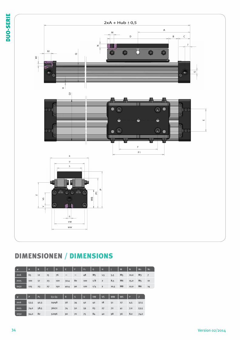
DIMENSIONEN / DIMENSIONS
ø A B C D E F F1 G H J M N M1 N1
2x16 65 12 15 76 — — 48 M5 1,5 5,5 M5 10,0 M3 7
2x25 100 17 23 120 32,4 80 100 1/8 2 8,5 M6 15,0 M5 10
2x32 125 23 27 150 40,4 90 120 1/4 2 10,5 M8 12,0 M6 14
ø P P1 Q x Q1 R S U VW VS WW WS Y Z
2x16 53,5 42,3 24x48 56 34 42 42 18 51 27 4,5 37,5
2x25 74,0 58,5 36x72 74 50 59 63 27 72 41 7,0 53,5
2x32 94,0 82 52x96 90 70 75 84 40 98 56 8,0 74,0
VS
Y
Z
Q
H
J
G
A
F 1
E
M
N
M1
N1
F
D B C
Q1
2xA + Hub 0,5
P1
P
WS
DU
O-S
ERIE
35Version 02/2014 35
DU
O-S
ERIE

36
F
LMv
Ma Mr
ha
y
hr hv
KRÄFTE UND MOMENTE
FORCES AND MOMENTS
Zylinder Kolbenkraft (N)
Dämpfung Max. Belastung (N) Max. Biegemoment (Nm)
Max. Verdrehmoment (Nm)
Bei 6 Bar (mm) DUO DUO DUO
Ø F S L Ma axial Mr radial Mv zentral
2x16 200 15 240 8,0 2,4 1,0
2x25 480 21 600 30,0 8,0 6,0
2x32
820 26 900 60,0 16,5 10,0
Cylinder Effect Force (N)
Cushioning Max. allowed load (N)
Max. allowed bending moments (Nm)
Max. allowed torque (Nm)
at 6 Bar (mm) DUO DUO DUO
Ø F S L Ma axial Mr radial Mv central
2x16 200 15 240 8,0 2,4 1,0
2x25 480 21 600 30,0 8,0 6,0
2x32 820 26 900 60,0 16,5 10,0
Die Tabellenangaben stellen die höchstzulässigen Werte bei stoß-freiem Betrieb und Geschwindigkeiten von v≤ 0,2m/sec [PL-Serie] – v≤ 0,45m/sec [PLF-Serie] dar. Max. 6 bar.Eine Überschreitung, auch kurzfristig, der Werte im dynamisierten Bereich ist unzulässig.
Achtung: Im grenznahen Einsatzfall können resultierende Kräfte zu einer Überschreitung der zulässigen Grenzwerte führen.Bei unde-finierbaren Situationen ist daher eine Unterschreitung der zulässi-gen Belastungswerte um 10–20% notwendig.
Bitte fragen Sie unseren Außendienst.
The figures above are max. values based on light shock free duty and speed of v≤ 0,2m/sec [PL-series] – v ≤ 0,45m/sec [PLF-series]. Max. pressure 6 bar.An exceeding of the values in dynamic operations, even for short moments, has to be avoided.
Attention: Resulting forces could lead to extreme exceedings of the values. In case of undefinable situations the above max. values have to be reduced by 10–20%.
Please ask our sales representatives
36
DU
O-S
ERIE
Formeln / FormulasM
a = F * h
a
Mr = F * h
r
Mv = F * h
v
DÄMPFUNGS-DIAGRAMM / CUSHIONING DIAGRAM
Bitte beachten Sie:
Bei Überschreitung der zulässigen Grenzwerte müssen externe Stoßdämpfer eingebaut
werden.
Bei Kolbengeschwindigkeiten ≥ 1m/s werden Vitondichtungen empfohlen.
Bei Kolbengeschwindigkeiten ≤ 0,1m/s (NBR), ≤ 0,2m/s (VITON) wird Spezialfett Nr. IX
empfohlen, siehe Ersatzteile.
Bei Kolbengeschwindigkeiten unter 1m/s wird eine optimale Dichtungs-Lebensdauer
erreicht.
Pay attention to the following points:
If the limits above are exceeded additional shock absorbers are necessary.
For piston speeds of more than ≥ 1m/s viton seals are recommended.
For piston speeds ≤ 0,1m/s (NBR), ≤ 0,2m/s (VITON) slow speed lubrication is necessary
see at sperpart kids
Maximum duration life will be achieved when piston speeds do not exceed 1m/s.
Kolben / Piston (m/s)
37
DU
O-S
ERIE
W2+
W3
G
W3 W2 Luftanschlüsse
Air connections
10
54
3
2
1
0,50,4
0,3
0,2
0,10,1 0,2 0,3 0,4 0,5 1 2 3 4 5 10 100 1000
Ø16
Ø25
Ø32
Ø40
Kolben
Masse / Cushioning Mass (kg)
Ma Ma
La
L
L
C C
B B
A A
L
LLr
LrMrMr
J H
G F
38
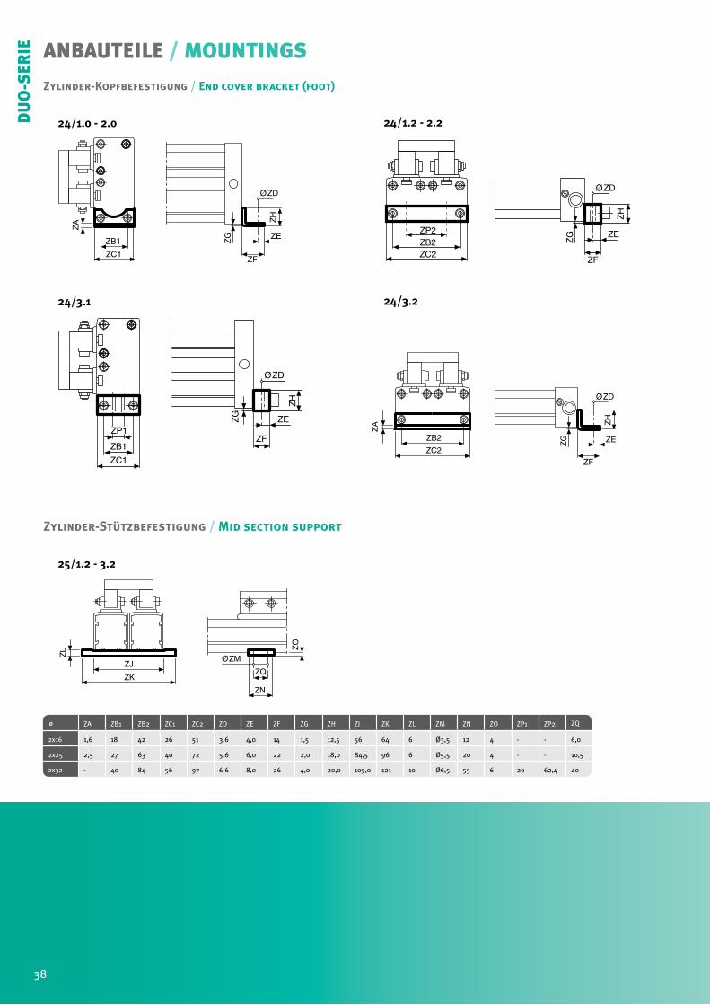
ANBAUTEILE / MOUNTINGS
ø ZA ZB1 ZB2 ZC1 ZC2 ZD ZE ZF ZG ZH ZJ ZK ZL ZM ZN ZO ZP1 ZP2 ZQ
2x16 1,6 18 42 26 51 3,6 4,0 14 1,5 12,5 56 64 6 Ø3,5 12 4 - - 6,0
2x25 2,5 27 63 40 72 5,6 6,0 22 2,0 18,0 84,5 96 6 Ø5,5 20 4 - - 10,5
2x32
- 40 84 56 97 6,6 8,0 26 4,0 20,0 109,0 121 10 Ø6,5 55 6 20 62,4 40
ZH
ØZD
ZF
ZEZG
ZC1
ZB1
ZP1
ZF
ZH
ØZD
ZEZG
ZA
ZC1
ZB1
ØZM
ZN
ZO
ZQZK
ZJ
ZL
ZH
ØZD
ZF
ZE
ZG
ZC2ZB2ZP2
ZH
ØZD
ZF
ZEZG
ZC2
ZB2
ZA
Zylinder-Stützbefestigung / Mid section support
Zylinder-Kopfbefestigung / End cover bracket (foot)
24/1.0 - 2.0
24/3.1
24/1.2 - 2.2
24/3.2
25/1.2 - 3.2
38
DU
O-S
ERIE
ANBAUTEILE / MOUNTINGS
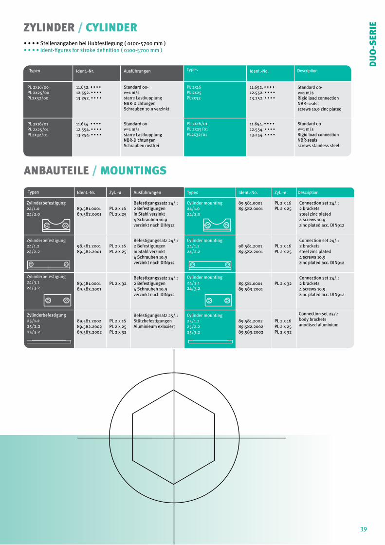
Typen Ident.-Nr. Ausführungen Types Ident.-No. Description
PL 2x16/00 PL 2x25/00 PL2x32/00
11.652. • • • •
12.552. • • • •
13.252. • • • •
Standard 00-v=1 m/sstarre LastkupplungNBR-DichtungenSchrauben 10.9 verzinkt
PL 2x16 PL 2x25PL2x32
11.652. • • • •
12.552. • • • •
13.252. • • • •
Standard 00- v=1 m/s Rigid load connection NBR-seals screws 10.9 zinc plated
PL 2x16/01 PL 2x25/01 PL2x32/01
11.654. • • • •
12.554. • • • •
13.254. • • • •
Standard 00-v=1 m/sstarre LastkupplungNBR-DichtungenSchrauben rostfrei
PL 2x16/01PL 2x25/01PL2x32/01
11.654. • • • •
12.554. • • • •
13.254. • • • •
Standard 00- v=1 m/s Rigid load connection NBR-seals screws stainless steel
Typen Ident.-Nr. Zyl. -ø Ausführungen Types Ident.-No. Zyl. -ø Description
Zylinderbefestigung24/1.024/2.0
89.581.000189.582.0001
PL 2 x 16PL 2 x 25
Befestigungssatz 24/.:2 Befestigungenin Stahl verzinkt4 Schrauben 10.9verzinkt nach DIN912
Cylinder mounting24/1.024/2.0
89.581.000189.582.0001
PL 2 x 16PL 2 x 25
Connection set 24/.:2 bracketssteel zinc plated4 screws 10.9zinc plated acc. DIN912
Zylinderbefestigung24/1.224/2.2
98.581.200189.582.2001
PL 2 x 16PL 2 x 25
Befestigungssatz 24/.:2 Befestigungenin Stahl verzinkt4 Schrauben 10.9verzinkt nach DIN912
Cylinder mounting24/1.224/2.2
98.581.200189.582.2001
PL 2 x 16PL 2 x 25
Connection set 24/.:2 bracketssteel zinc plated4 screws 10.9zinc plated acc. DIN912
Zylinderbefestigung24/3.124/3.2
89.581.000189.583.2001
PL 2 x 32Befestigungssatz 24/.:2 Befestigungen4 Schrauben 10.9verzinkt nach DIN912
Cylinder mounting24/3.124/3.2
89.581.000189.583.2001
PL 2 x 32Connection set 24/.:2 brackets4 screws 10.9zinc plated acc. DIN912
Zylinderbefestigung 25/1.2 25/2.2 25/3.2
89.581.200289.582.200289.583.2002
PL 2 x 16PL 2 x 25PL 2 x 32
Befestigungssatz 25/.:StützbefestigungenAluminieum exloxiert
Cylinder mounting25/1.225/2.225/3.2
89.581.200289.582.200289.583.2002
PL 2 x 16PL 2 x 25PL 2 x 32
Connection set 25/.: body brackets anodised aluminium
ZYLINDER / CYLINDER• • • • Stellenangaben bei Hubfestlegung ( 0100-5700 mm )• • • • Ident-figures for stroke definition ( 0100-5700 mm )
39
DU
O-S
ERIE
40 Version 02/2014
PLGPLG
SER
IE
DER LEISE
PLG - SERIESTHE SILENT
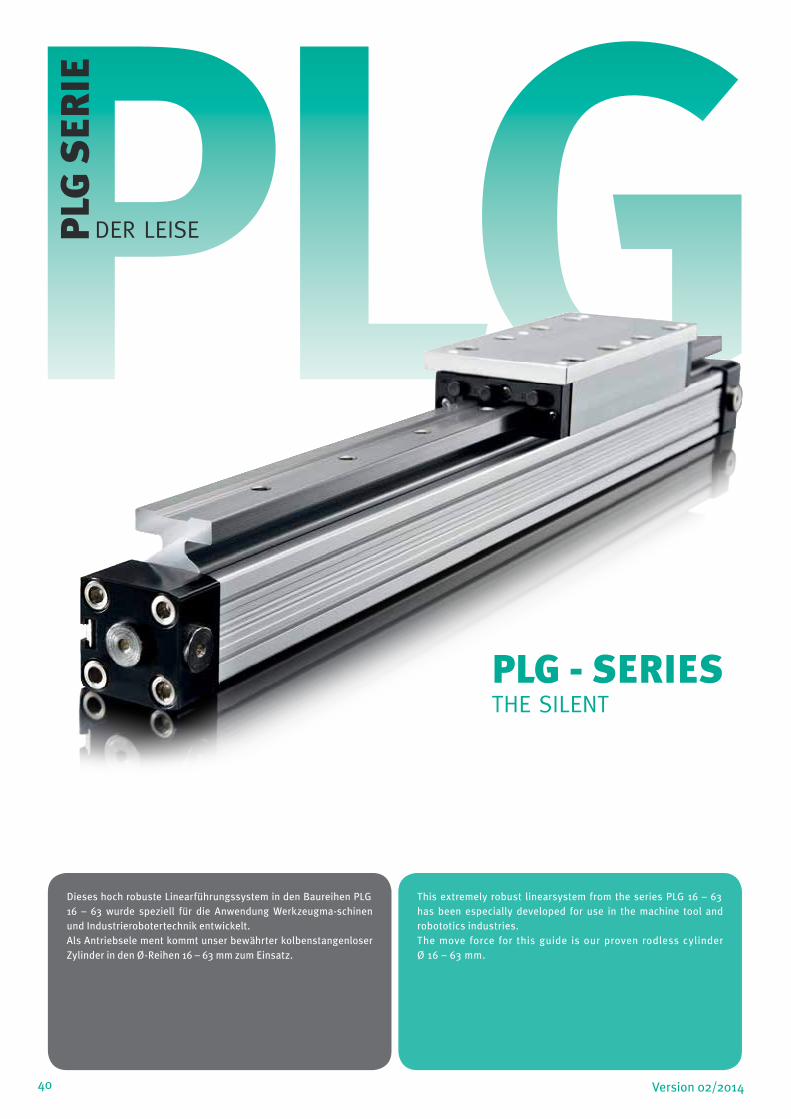
Dieses hoch robuste Linearführungssystem in den Baureihen PLG 16 – 63 wurde speziell für die Anwendung Werkzeugma-schinen und Industrierobotertechnik entwickelt.Als Antriebsele ment kommt unser bewährter kolbenstangenloser Zylinder in den Ø-Reihen 16 – 63 mm zum Einsatz.
This extremely robust linearsystem from the series PLG 16 – 63 has been especially developed for use in the machine tool and robototics industries.The move force for this guide is our proven rodless cylinder Ø 16 – 63 mm.
Änderung und Irrtum auf allen Seiten vorbehalten / Alterations and errors reserved on all pages
41Version 02/2014
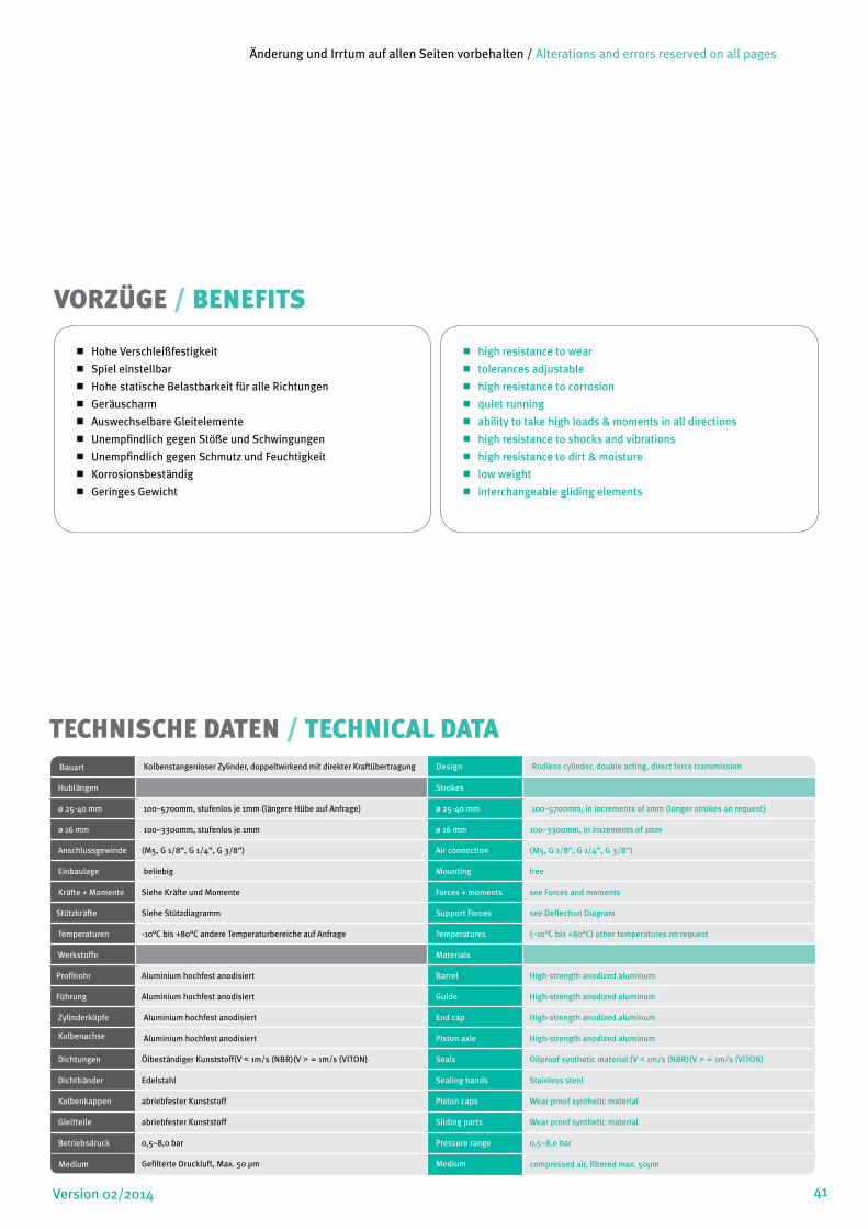
Hohe Verschleißfestigkeit
Spiel einstellbar
Hohe statische Belastbarkeit für alle Richtungen
Geräuscharm
Auswechselbare Gleitelemente
Unempfindlich gegen Stöße und Schwingungen
Unempfindlich gegen Schmutz und Feuchtigkeit
Korrosionsbeständig
Geringes Gewicht
high resistance to wear
tolerances adjustable
high resistance to corrosion
quiet running
ability to take high loads & moments in all directions
high resistance to shocks and vibrations
high resistance to dirt & moisture
low weight
interchangeable gliding elements
VORZÜGE / BENEFITS
TECHNISCHE DATEN / TECHNICAL DATABauart Kolbenstangenloser Zylinder, doppeltwirkend mit direkter Kraftübertragung Design Rodless cylinder, double acting, direct force transmission
Hublängen Strokes
ø 25-40 mm 100–5700mm, stufenlos je 1mm (längere Hübe auf Anfrage) ø 25-40 mm 100–5700mm, in increments of 1mm (longer strokes on request)
ø 16 mm 100–3300mm, stufenlos je 1mm ø 16 mm 100–3300mm, in increments of 1mm
Anschlussgewinde (M5, G 1/8“, G 1/4“, G 3/8“) Air connection (M5, G 1/8“, G 1/4“, G 3/8“)
Einbaulage beliebig Mounting free
Kräfte + Momente Siehe Kräfte und Momente Forces + moments see Forces and moments
Stützkräfte Siehe Stützdiagramm Support Forces see Deflection Diagram
Temperaturen -10°C bis +80°C andere Temperaturbereiche auf Anfrage Temperatures (–10°C bis +80°C) other temperatures on request
Werkstoffe Materials
Profilrohr Aluminium hochfest anodisiert Barrel High-strength anodized aluminum
Führung Aluminium hochfest anodisiert Guide High-strength anodized aluminum
Zylinderköpfe Aluminium hochfest anodisiert End cap High-strength anodized aluminum
Kolbenachse Aluminium hochfest anodisiert Piston axle High-strength anodized aluminum
Dichtungen Ölbeständiger Kunststoff(V < 1m/s (NBR)(V > = 1m/s (VITON) Seals Oilproof synthetic material (V < 1m/s (NBR)(V > = 1m/s (VITON)
Dichtbänder Edelstahl Sealing bands Stainless steel
Kolbenkappen abriebfester Kunststoff Piston caps Wear proof synthetic material
Gleitteile abriebfester Kunststoff Sliding parts Wear proof synthetic material
Betriebsdruck 0,5–8,0 bar Pressure range 0,5–8,0 bar
Medium Gefilterte Druckluft, Max. 50 µm Medium compressed air, filtered max. 50µm
42 Version 02/2014
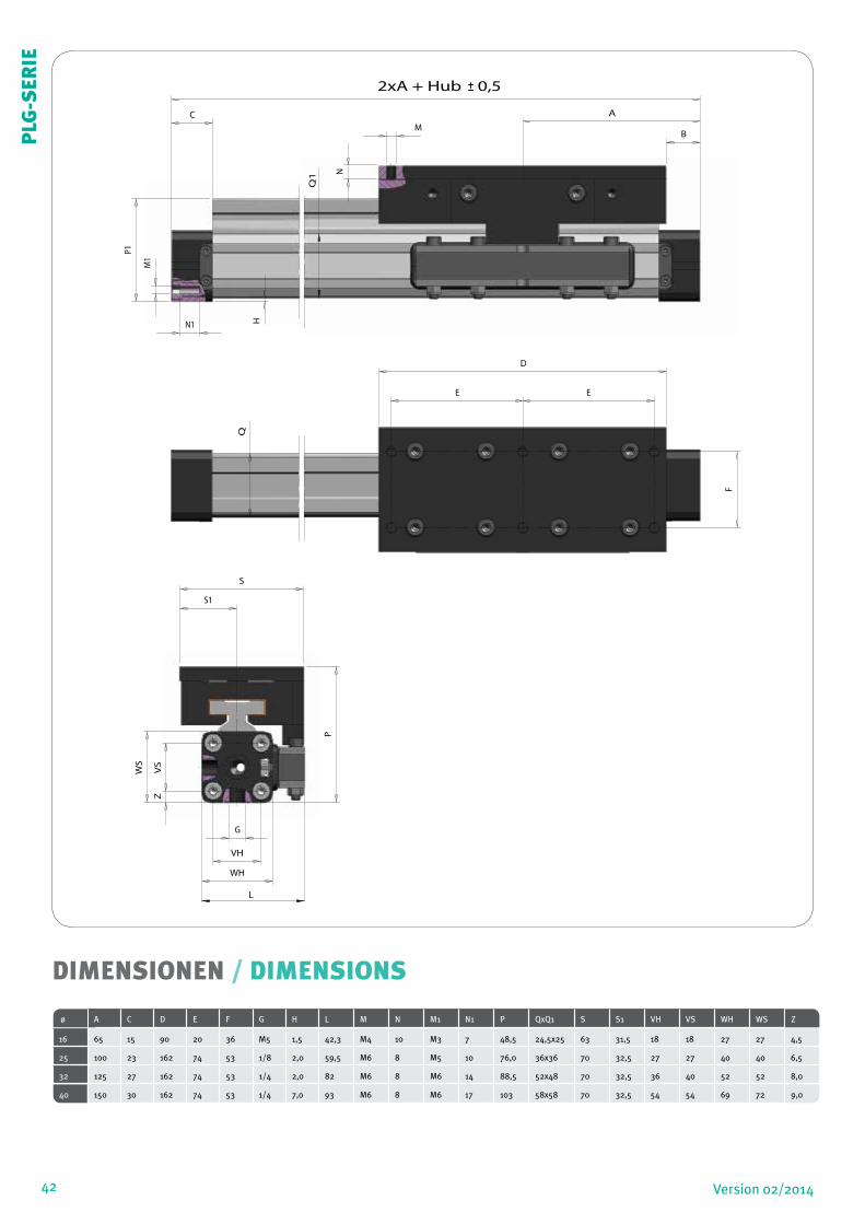
DIMENSIONEN / DIMENSIONS
ø A C D E F G H L M N M1 N1 P QxQ1 S S1 VH VS WH WS Z
16 65 15 90 20 36 M5 1,5 42,3 M4 10 M3 7 48,5 24,5x25 63 31,5 18 18 27 27 4,5
25 100 23 162 74 53 1/8 2,0 59,5 M6 8 M5 10 76,0 36x36 70 32,5 27 27 40 40 6,5
32 125 27 162 74 53 1/4 2,0 82 M6 8 M6 14 88,5 52x48 70 32,5 36 40 52 52 8,0
40 150 30 162 74 53 1/4 7,0 93 M6 8 M6 17 103 58x58 70 32,5 54 54 69 72 9,0
B
S
P
VH
VS
Z
F
S1
G
WH
L
WS
B
C
VH
VS
Z
F
E E
S1A
D
P1
H
WH
L
WS
Q
M
NN1
M1
Q1
2xA + Hub 0,5
PLG
-SER
IE
43Version 02/2014
L
Mv
Ma
Mr
F
ha
y
hr hv
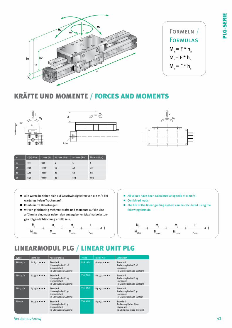
Alle Werte beziehen sich auf Geschwindigkeiten von 0,2 m/s bei
wartungsfreiem Trockenlauf.
Kombinierte Belastungen
Wirken gleichzeitig mehrere Kräfte und Momente auf die Line-
arführung ein, muss neben den angegebenen Maximalbelastun-
gen folgende Gleichung erfüllt sein:
All values have been calculated at sppeds of 0,2m/s.
Combined loads
The life of the linear guiding system can be calculated using the
following formula
KRÄFTE UND MOMENTE / FORCES AND MOMENTS
LINEARMODUL PLG / LINEAR UNIT PLG
ø F (N) 6 bar L max (N) Mr max (Nm) Ma max (Nm) Mv Max (Nm)
16 110 350 4 6 6
25 250 1000 14 40 40
32 420 2000 24 68 68
40 640 2800 37 103 103
Typen Ident.-Nr. Ausführungen Types Ident.-No. Description
PLG 16/2 61.692. • • • • StandardLinearzylinder PL16Lineareinheit(2-Gleitwagen-System)
PLG 16/2 61.692. • • • • StandardRodless cylinder PL16Linear unit(2-Gliding carriage-System)
PLG 25/2 62.592. • • • • StandardLinearzylinder PL25Lineareinheit(2-Gleitwagen-System)
PLG 25/2 62.592. • • • • StandardRodless cylinder PL25Linear unit(2-Gliding carriage-System)
PLG 32/2 63.292. • • • • StandardLinearzylinder PL32Lineareinheit(2-Gleitwagen-System)
PLG 32/2 63.292. • • • • StandardRodless cylinder PL32Linear unit(2-Gliding carriage-System
PLG 40 64.092. • • • • StandardLinearzylinder PL40Lineareinheit(2-Gleitwagen-System)
PLG 40/2 64.092. • • • • StandardRodless cylinder PL40Linear unit(2-Gliding carriage-System)
MrL
sx
Ma
6 bar
sy
L
Mv
Ma
Ma max
+ + + 1 Mr
Mr max
Mv
Mv max
L
L max
PLG
-SER
IEMa
Ma max
+ + + 1 Mr
Mr max
Mv
Mv max
L
L max
Formeln / FormulasM
a = F * h
a
Mr = F * h
r
Mv = F * h
v
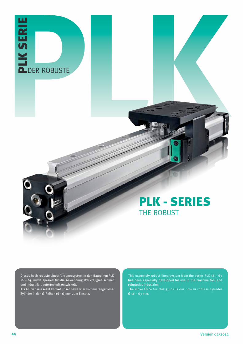
44 Version 02/2014
PLKPLK
SER
IE
DER ROBUSTE
Dieses hoch robuste Linearführungssystem in den Baureihen PLK 16 – 63 wurde speziell für die Anwendung Werkzeugma-schinen und Industrierobotertechnik entwickelt.Als Antriebsele ment kommt unser bewährter kolbenstangenloser Zylinder in den Ø-Reihen 16 – 63 mm zum Einsatz.
This extremely robust linearsystem from the series PLK 16 – 63 has been especially developed for use in the machine tool and robototics industries.The move force for this guide is our proven rodless cylinder Ø 16 – 63 mm.
PLK - SERIESTHE ROBUST
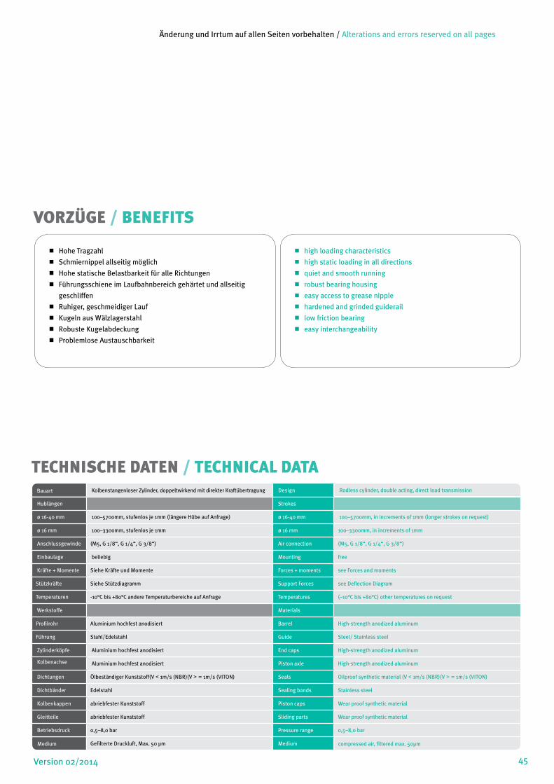
Hohe Tragzahl
Schmiernippel allseitig möglich
Hohe statische Belastbarkeit für alle Richtungen
Führungsschiene im Laufbahnbereich gehärtet und allseitig
geschliffen
Ruhiger, geschmeidiger Lauf
Kugeln aus Wälzlagerstahl
Robuste Kugelabdeckung
Problemlose Austauschbarkeit
high loading characteristics
high static loading in all directions
quiet and smooth running
robust bearing housing
easy access to grease nipple
hardened and grinded guiderail
low friction bearing
easy interchangeability
VORZÜGE / BENEFITS
45Version 02/2014
TECHNISCHE DATEN / TECHNICAL DATABauart Kolbenstangenloser Zylinder, doppeltwirkend mit direkter Kraftübertragung Design Rodless cylinder, double acting, direct load transmission
Hublängen Strokes
ø 16-40 mm 100–5700mm, stufenlos je 1mm (längere Hübe auf Anfrage) ø 16-40 mm 100–5700mm, in increments of 1mm (longer strokes on request)
ø 16 mm 100–3300mm, stufenlos je 1mm ø 16 mm 100–3300mm, in increments of 1mm
Anschlussgewinde (M5, G 1/8“, G 1/4“, G 3/8“) Air connection (M5, G 1/8“, G 1/4“, G 3/8“)
Einbaulage beliebig Mounting free
Kräfte + Momente Siehe Kräfte und Momente Forces + moments see Forces and moments
Stützkräfte Siehe Stützdiagramm Support Forces see Deflection Diagram
Temperaturen -10°C bis +80°C andere Temperaturbereiche auf Anfrage Temperatures (–10°C bis +80°C) other temperatures on request
Werkstoffe Materials
Profilrohr Aluminium hochfest anodisiert Barrel High-strength anodized aluminum
Führung Stahl/Edelstahl Guide Steel/ Stainless steel
Zylinderköpfe Aluminium hochfest anodisiert End caps High-strength anodized aluminum
Kolbenachse Aluminium hochfest anodisiert Piston axle High-strength anodized aluminum
Dichtungen Ölbeständiger Kunststoff(V < 1m/s (NBR)(V > = 1m/s (VITON) Seals Oilproof synthetic material (V < 1m/s (NBR)(V > = 1m/s (VITON)
Dichtbänder Edelstahl Sealing bands Stainless steel
Kolbenkappen abriebfester Kunststoff Piston caps Wear proof synthetic material
Gleitteile abriebfester Kunststoff Sliding parts Wear proof synthetic material
Betriebsdruck 0,5–8,0 bar Pressure range 0,5–8,0 bar
Medium Gefilterte Druckluft, Max. 50 µm Medium compressed air, filtered max. 50µm
Änderung und Irrtum auf allen Seiten vorbehalten / Alterations and errors reserved on all pages
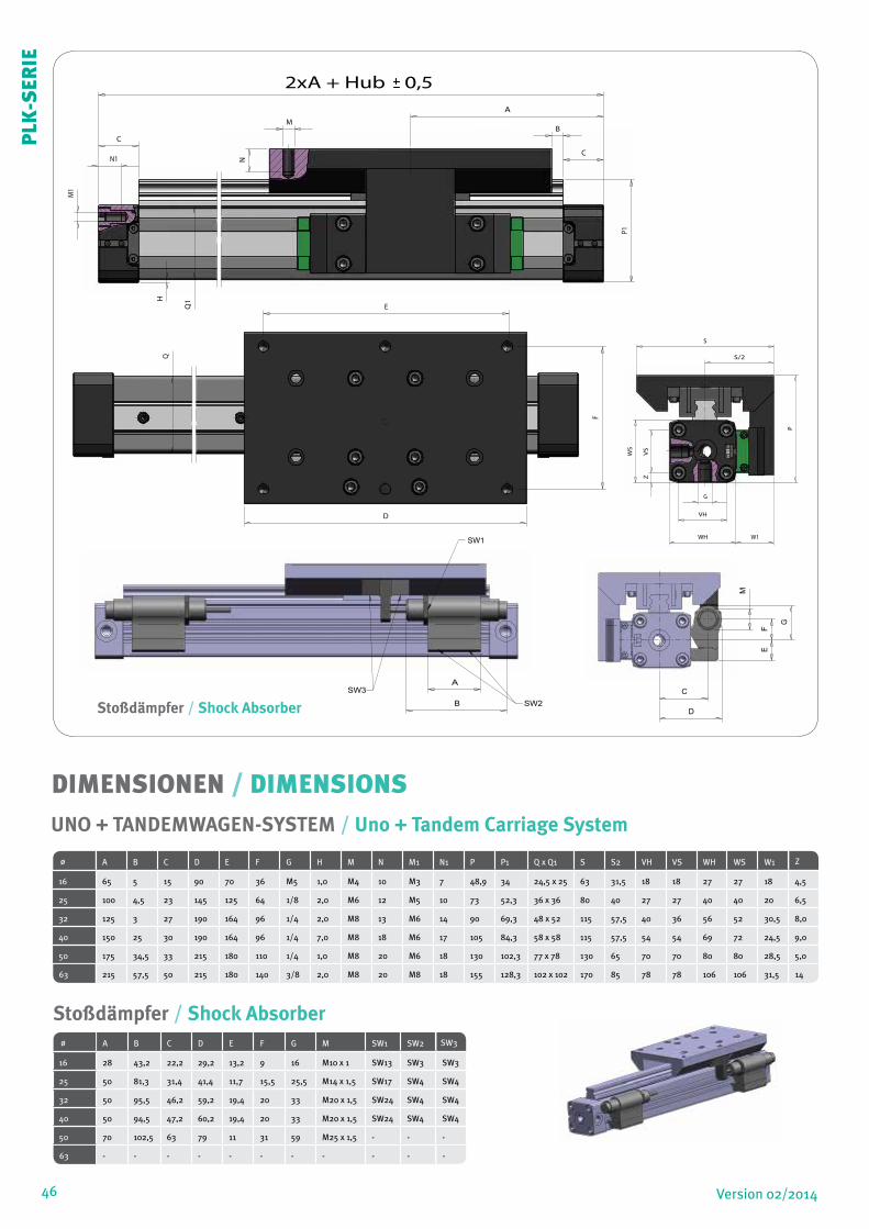
46 Version 02/2014
C
B
A
N1
M
E
D
G
VH
WH W1
S
S/2
M1
N
VS
Z
P
P1
C
F
H
QQ1
WS
2xA + Hub 0,5
C
B
A
N1
M
E
D
G
VH
WH W1
S
S/2
M1
N
VS
Z
P
P1
C
F
H
QQ1
WS
2xA + Hub 0,5
C
B
A
N1
M
E
D
G
VH
WH W1
S
S/2
M1
N
VS
Z
P
P1
C
F
H
QQ1
WS
2xA + Hub 0,5
C
D
FE
A
B
M
SW1
SW2
SW3
G
C
D
FE
A
B
M
SW1
SW2
SW3
G
Stoßdämpfer / Shock Absorber
C
D
A
B
SW1
SW2
SW3
DIMENSIONEN / DIMENSIONS
Stoßdämpfer / Shock Absorber
ø A B C D E F G H M N M1 N1 P P1 Q x Q1 S S2 VH VS WH WS W1 Z
16 65 5 15 90 70 36 M5 1,0 M4 10 M3 7 48,9 34 24,5 x 25 63 31,5 18 18 27 27 18 4,5
25 100 4,5 23 145 125 64 1/8 2,0 M6 12 M5 10 73 52,3 36 x 36 80 40 27 27 40 40 20 6,5
32 125 3 27 190 164 96 1/4 2,0 M8 13 M6 14 90 69,3 48 x 52 115 57,5 40 36 56 52 30,5 8,0
40 150 25 30 190 164 96 1/4 7,0 M8 18 M6 17 105 84,3 58 x 58 115 57,5 54 54 69 72 24,5 9,0
50 175 34,5 33 215 180 110 1/4 1,0 M8 20 M6 18 130 102,3 77 x 78 130 65 70 70 80 80 28,5 5,0
63 215 57,5 50 215 180 140 3/8 2,0 M8 20 M8 18 155 128,3 102 x 102 170 85 78 78 106 106 31,5 14
UNO + TANDEMWAGEN-SYSTEM / Uno + Tandem Carriage System
ø A B C D E F G M SW1 SW2 SW3
16 28 43,2 22,2 29,2 13,2 9 16 M10 x 1 SW13 SW3 SW3
25 50 81,3 31,4 41,4 11,7 15,5 25,5 M14 x 1,5 SW17 SW4 SW4
32 50 95,5 46,2 59,2 19,4 20 33 M20 x 1,5 SW24 SW4 SW4
40 50 94,5 47,2 60,2 19,4 20 33 M20 x 1,5 SW24 SW4 SW4
50 70 102,5 63 79 11 31 59 M25 x 1,5 - - -
63 - - - - - - - - - - -
PLK
-SER
IE
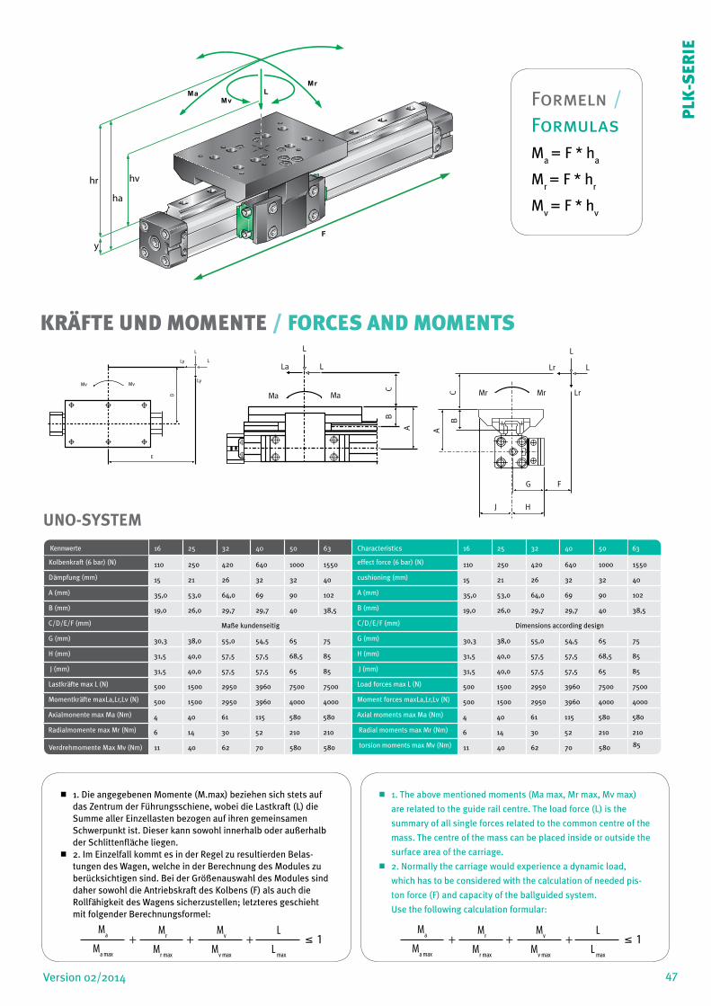
47Version 02/2014
1. Die angegebenen Momente (M.max) beziehen sich stets auf das Zentrum der Führungsschiene, wobei die Lastkraft (L) die Summe aller Einzellasten bezogen auf ihren gemeinsamen Schwerpunkt ist. Dieser kann sowohl innerhalb oder außerhalb der Schlittenfläche liegen.
2. Im Einzelfall kommt es in der Regel zu resultierden Belas-tungen des Wagen, welche in der Berechnung des Modules zu berücksichtigen sind. Bei der Größenauswahl des Modules sind daher sowohl die Antriebskraft des Kolbens (F) als auch die Rollfähigkeit des Wagens sicherzustellen; letzteres geschieht mit folgender Berechnungsformel:
1. The above mentioned moments (Ma max, Mr max, Mv max)
are related to the guide rail centre. The load force (L) is the
summary of all single forces related to the common centre of the
mass. The centre of the mass can be placed inside or outside the
surface area of the carriage.
2. Normally the carriage would experience a dynamic load,
which has to be considered with the calculation of needed pis-
ton force (F) and capacity of the ballguided system.
Use the following calculation formular:
Kennwerte 16 25 32 40 50 63 Characteristics 16 25 32 40 50 63
Kolbenkraft (6 bar) (N) 110 250 420 640 1000 1550 effect force (6 bar) (N) 110 250 420 640 1000 1550
Dämpfung (mm) 15 21 26 32 32 40 cushioning (mm) 15 21 26 32 32 40
A (mm) 35,0 53,0 64,0 69 90 102 A (mm) 35,0 53,0 64,0 69 90 102
B (mm) 19,0 26,0 29,7 29,7 40 38,5 B (mm) 19,0 26,0 29,7 29,7 40 38,5
C/D/E/F (mm) Maße kundenseitig C/D/E/F (mm) Dimensions according design
G (mm) 30,3 38,0 55,0 54,5 65 75 G (mm) 30,3 38,0 55,0 54,5 65 75
H (mm) 31,5 40,0 57,5 57,5 68,5 85 H (mm) 31,5 40,0 57,5 57,5 68,5 85
J (mm) 31,5 40,0 57,5 57,5 65 85 J (mm) 31,5 40,0 57,5 57,5 65 85
Lastkräfte max L (N) 500 1500 2950 3960 7500 7500 Load forces max L (N) 500 1500 2950 3960 7500 7500
Momentkräfte maxLa,Lr,Lv (N) 500 1500 2950 3960 4000 4000 Moment forces maxLa,Lr,Lv (N) 500 1500 2950 3960 4000 4000
Axialmonente max Ma (Nm) 4 40 61 115 580 580 Axial moments max Ma (Nm) 4 40 61 115 580 580
Radialmomente max Mr (Nm) 6 14 30 52 210 210 Radial moments max Mr (Nm) 6 14 30 52 210 210
Verdrehmomente Max Mv (Nm) 11 40 62 70 580 580 torsion moments max Mv (Nm) 11 40 62 70 580 85
PLF 16-40
L
L
R
T
Z-Z*
P-P
1
Z1
W3
V3
W2
W1
Z2
P1
Y
M
S
U
KoKo
VH
WH
RT
Z-Z
*
P-P
1
Z1
W3 V3
W2
W1
Z2
P1
Y
M
SU
VH
WH
M1, N
LuftanschlüsseAir connections
( A + Hub / stroke / course ) 0,5±
B + Hub / stroke / courseC D
E
F
K
B C
J
H
G
M, N
Q x
Q1
O
PL 16-32 PL 40-63PL 32-40
PL 16-25 PL 32-40(Hub / Stroke / course + 2 x A) 0,5±
C
L
Q x
Q1
A
H
J
W2+
W3
G
PLF 50-63
W3 W2
YH
S
WH
M1, N
W3
W1W1
YKP
YYS
PLF 40-63
LuftanschlüsseAir connections
S
U
YH
WH
P
YSY
WS
W1
W4
PLF 16-32
Nur bei PLF 32 M, N1
D
E
B
U Q
SL
SL
SL
10
54
3
2
1
0,50,4
0,3
0,2
0,10,1 0,2 0,3 0,4 0,5 1 2 3 4 5 10 100 1000
0,16
0,25
0,32
0,40
Kolben
Masse / Cushioning Mass (kg)
Mv Mv
Ly
L
L
Ly
E
D Ma Ma
La
L
L
C C
B B
A A
L
LLr
LrMrMr
J H
G F
KRÄFTE UND MOMENTE / FORCES AND MOMENTS
L
Mv
Ma
Mr
F
ha
y
hr hv
UNO-SYSTEM
PLK
-SER
IE
Ma
Ma max
+ + + 1 Mr
Mr max
Mv
Mv max
L
L max
Ma
Ma max
+ + + 1 Mr
Mr max
Mv
Mv max
L
L max
Formeln / FormulasM
a = F * h
a
Mr = F * h
r
Mv = F * h
v
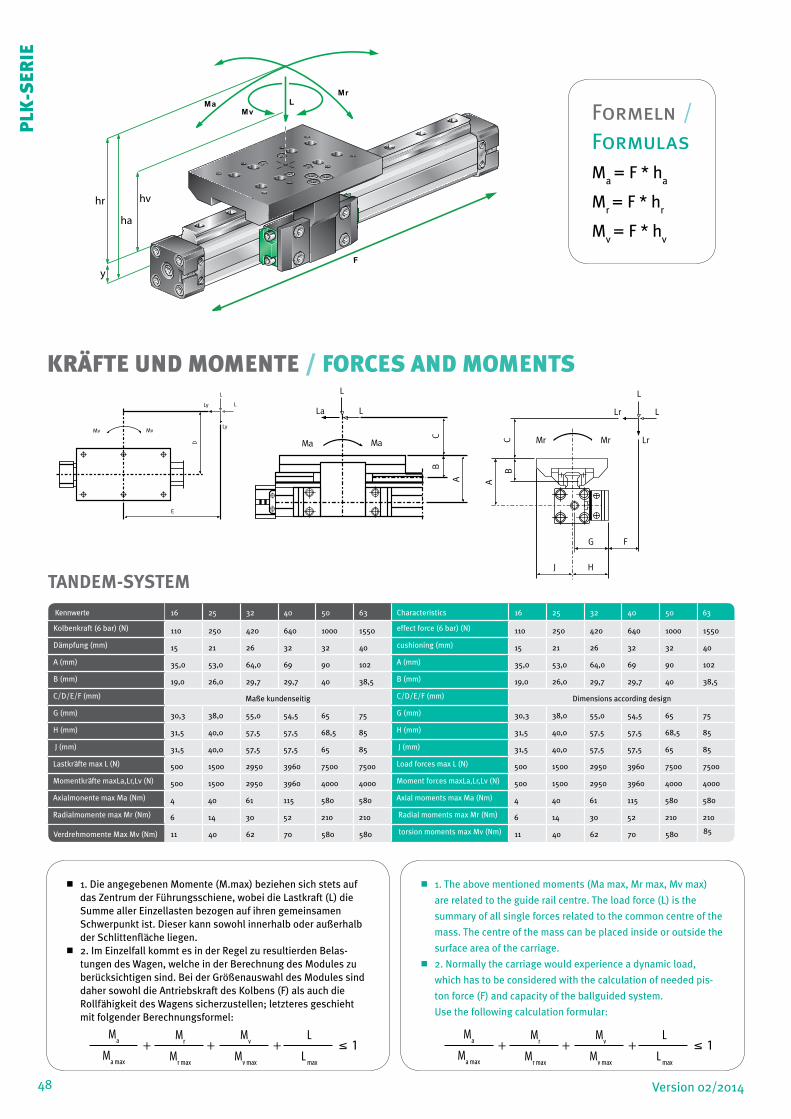
48 Version 02/2014
1. Die angegebenen Momente (M.max) beziehen sich stets auf das Zentrum der Führungsschiene, wobei die Lastkraft (L) die Summe aller Einzellasten bezogen auf ihren gemeinsamen Schwerpunkt ist. Dieser kann sowohl innerhalb oder außerhalb der Schlittenfläche liegen.
2. Im Einzelfall kommt es in der Regel zu resultierden Belas-tungen des Wagen, welche in der Berechnung des Modules zu berücksichtigen sind. Bei der Größenauswahl des Modules sind daher sowohl die Antriebskraft des Kolbens (F) als auch die Rollfähigkeit des Wagens sicherzustellen; letzteres geschieht mit folgender Berechnungsformel:
1. The above mentioned moments (Ma max, Mr max, Mv max)
are related to the guide rail centre. The load force (L) is the
summary of all single forces related to the common centre of the
mass. The centre of the mass can be placed inside or outside the
surface area of the carriage.
2. Normally the carriage would experience a dynamic load,
which has to be considered with the calculation of needed pis-
ton force (F) and capacity of the ballguided system.
Use the following calculation formular:
Ma
Ma max
+ + + 1 Mr
Mr max
Mv
Mv max
L
L max
Ma
Ma max
+ + + 1 Mr
Mr max
Mv
Mv max
L
L max
PLF 16-40
L
L
R
T
Z-Z*
P-P
1
Z1
W3
V3
W2
W1
Z2
P1
Y
M
S
U
KoKo
VH
WH
RT
Z-Z
*
P-P
1
Z1
W3 V3
W2
W1
Z2
P1
Y
M
SU
VH
WH
M1, N
LuftanschlüsseAir connections
( A + Hub / stroke / course ) 0,5±
B + Hub / stroke / courseC D
E
F
K
B C
J
H
G
M, N
Q x
Q1
O
PL 16-32 PL 40-63PL 32-40
PL 16-25 PL 32-40(Hub / Stroke / course + 2 x A) 0,5±
C
L
Q x
Q1
A
H
J
W2+
W3
G
PLF 50-63
W3 W2
YH
S
WH
M1, N
W3
W1W1
YKP
YYS
PLF 40-63
LuftanschlüsseAir connections
S
U
YH
WH
P
YSY
WS
W1
W4
PLF 16-32
Nur bei PLF 32 M, N1
D
E
B
U Q
SL
SL
SL
10
54
3
2
1
0,50,4
0,3
0,2
0,10,1 0,2 0,3 0,4 0,5 1 2 3 4 5 10 100 1000
0,16
0,25
0,32
0,40
Kolben
Masse / Cushioning Mass (kg)
Mv Mv
Ly
L
L
Ly
E
D Ma Ma
La
L
L
C C
B B
A A
L
LLr
LrMrMr
J H
G F
KRÄFTE UND MOMENTE / FORCES AND MOMENTS
TANDEM-SYSTEM
Kennwerte 16 25 32 40 50 63 Characteristics 16 25 32 40 50 63
Kolbenkraft (6 bar) (N) 110 250 420 640 1000 1550 effect force (6 bar) (N) 110 250 420 640 1000 1550
Dämpfung (mm) 15 21 26 32 32 40 cushioning (mm) 15 21 26 32 32 40
A (mm) 35,0 53,0 64,0 69 90 102 A (mm) 35,0 53,0 64,0 69 90 102
B (mm) 19,0 26,0 29,7 29,7 40 38,5 B (mm) 19,0 26,0 29,7 29,7 40 38,5
C/D/E/F (mm) Maße kundenseitig C/D/E/F (mm) Dimensions according design
G (mm) 30,3 38,0 55,0 54,5 65 75 G (mm) 30,3 38,0 55,0 54,5 65 75
H (mm) 31,5 40,0 57,5 57,5 68,5 85 H (mm) 31,5 40,0 57,5 57,5 68,5 85
J (mm) 31,5 40,0 57,5 57,5 65 85 J (mm) 31,5 40,0 57,5 57,5 65 85
Lastkräfte max L (N) 500 1500 2950 3960 7500 7500 Load forces max L (N) 500 1500 2950 3960 7500 7500
Momentkräfte maxLa,Lr,Lv (N) 500 1500 2950 3960 4000 4000 Moment forces maxLa,Lr,Lv (N) 500 1500 2950 3960 4000 4000
Axialmonente max Ma (Nm) 4 40 61 115 580 580 Axial moments max Ma (Nm) 4 40 61 115 580 580
Radialmomente max Mr (Nm) 6 14 30 52 210 210 Radial moments max Mr (Nm) 6 14 30 52 210 210
Verdrehmomente Max Mv (Nm) 11 40 62 70 580 580 torsion moments max Mv (Nm) 11 40 62 70 580 85
PLK
-SER
IE
Formeln / FormulasM
a = F * h
a
Mr = F * h
r
Mv = F * h
v
L
Mv
Ma
Mr
F
ha
y
hr hv
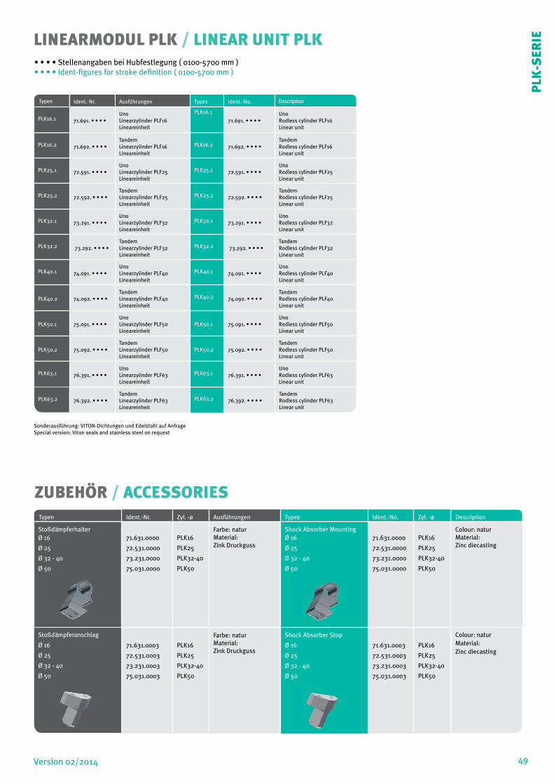
49Version 02/2014
Typen Ident.-Nr. Ausführungen Types Ident.-No. Description
PLK16.1 71.691. • • • •UnoLinearzylinder PLF16Lineareinheit
PLK16.1
71.691. • • • •UnoRodless cylinder PLF16Linear unit
PLK16.2 71.692. • • • •TandemLinearzylinder PLF16Lineareinheit
PLK16.2 71.692. • • • •TandemRodless cylinder PLF16Linear unit
PLK25.1 72.591. • • • •
UnoLinearzylinder PLF25Lineareinheit
PLK25.1 72.591. • • • •
UnoRodless cylinder PLF25Linear unit
PLK25.2 72.592. • • • •TandemLinearzylinder PLF25Lineareinheit
PLK25.2 72.592. • • • •TandemRodless cylinder PLF25Linear unit
PLK32.1 73.291. • • • •
UnoLinearzylinder PLF32Lineareinheit
PLK32.1 73.291. • • • •
UnoRodless cylinder PLF32Linear unit
PLK32.2 73.292. • • • •
TandemLinearzylinder PLF32Lineareinheit
PLK32.2 73.292. • • • •
TandemRodless cylinder PLF32Linear unit
PLK40.1 74.091. • • • •
UnoLinearzylinder PLF40Lineareinheit
PLK40.1 74.091. • • • •
UnoRodless cylinder PLF40Linear unit
PLK40.2 74.092. • • • •TandemLinearzylinder PLF40Lineareinheit
PLK40.2 74.092. • • • •Tandem Rodless cylinder PLF40Linear unit
PLK50.1 75.091. • • • •UnoLinearzylinder PLF50Lineareinheit
PLK50.1 75.091. • • • •UnoRodless cylinder PLF50Linear unit
PLK50.2 75.092. • • • •TandemLinearzylinder PLF50Lineareinheit
PLK50.2 75.092. • • • •Tandem Rodless cylinder PLF50Linear unit
PLK63.1 76.391. • • • •UnoLinearzylinder PLF63Lineareinheit
PLK63.1 76.391. • • • •UnoRodless cylinder PLF63Linear unit
PLK63.2 76.392. • • • •
TandemLinearzylinder PLF63Lineareinheit
PLK63.2 76.392. • • • •
Tandem Rodless cylinder PLF63 Linear unit
Sonderausführung: VITON-Dichtungen und Edelstahl auf AnfrageSpecial version: Viton seals and stainless steel on request
LINEARMODUL PLK / LINEAR UNIT PLK
ZUBEHÖR / ACCESSORIES
• • • • Stellenangaben bei Hubfestlegung ( 0100-5700 mm )• • • • Ident-figures for stroke definition ( 0100-5700 mm )
Typen Ident.-Nr. Zyl. -ø Ausführungen Types Ident.-No. Zyl. -ø Description
StoßdämpferhalterØ 16
Ø 25
Ø 32 - 40
Ø 50
71.631.0000
72.531.0000
73.231.0000
75.031.0000
PLK16
PLK25
PLK32-40
PLK50
Farbe: naturMaterial: Zink Druckguss
Shock Absorber MountingØ 16
Ø 25
Ø 32 - 40
Ø 50
71.631.0000
72.531.0000
73.231.0000
75.031.0000
PLK16
PLK25
PLK32-40
PLK50
Colour: naturMaterial: Zinc diecasting
Stoßdämpferanschlag
Ø 16
Ø 25
Ø 32 - 40
Ø 50
71.631.0003
72.531.0003
73.231.0003
75.031.0003
PLK16
PLK25
PLK32-40
PLK50
Farbe: naturMaterial: Zink Druckguss
Shock Absorber Stop
Ø 16
Ø 25
Ø 32 - 40
Ø 50
71.631.0003
72.531.0003
73.231.0003
75.031.0003
PLK16
PLK25
PLK32-40
PLK50
Colour: naturMaterial: Zinc diecasting
PLK
-SER
IE
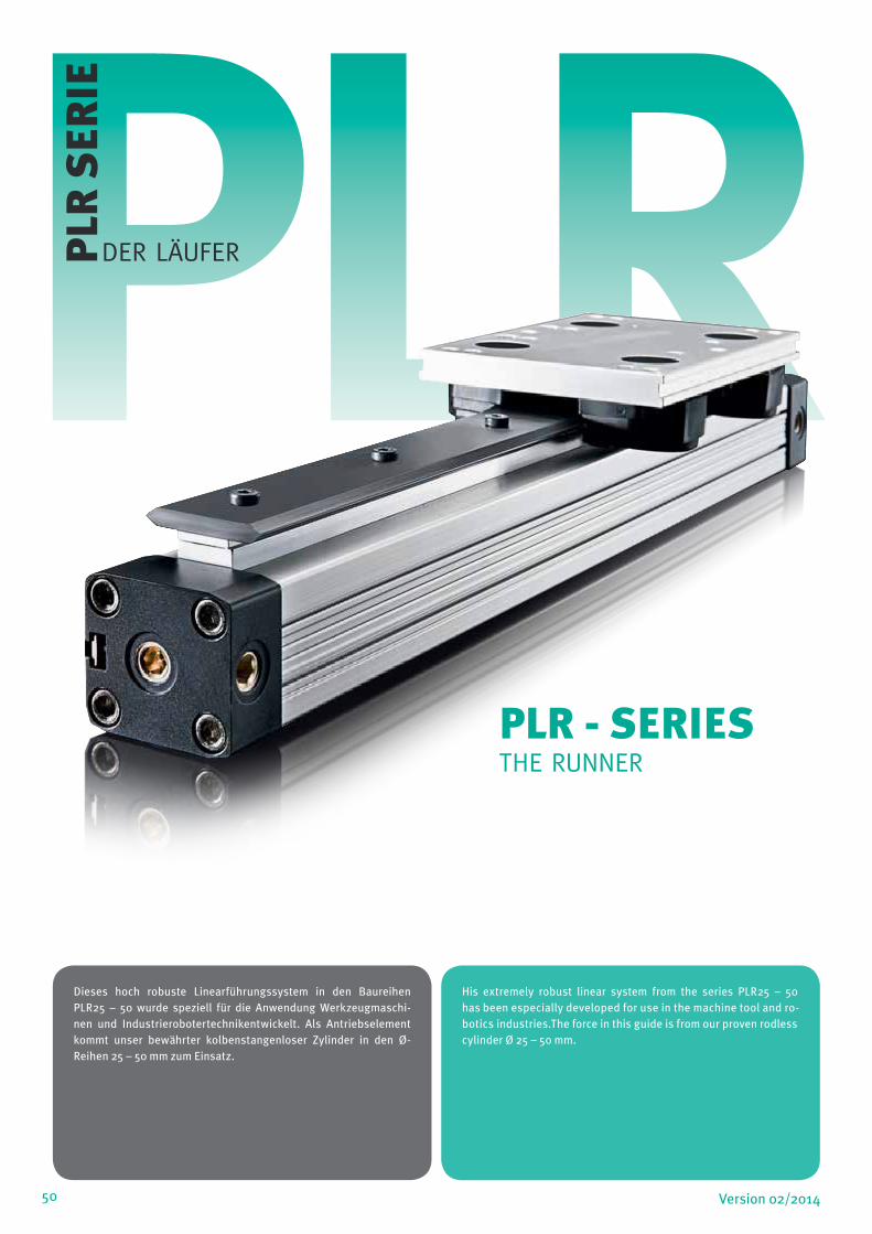
50 Version 02/2014
Dieses hoch robuste Linearführungssystem in den Baureihen PLR25 – 50 wurde speziell für die Anwendung Werkzeugmaschi-nen und Industrierobotertechnikentwickelt. Als Antriebselement kommt unser bewährter kolbenstangenloser Zylinder in den Ø-Reihen 25 – 50 mm zum Einsatz.
His extremely robust linear system from the series PLR25 – 50 has been especially developed for use in the machine tool and ro-botics industries.The force in this guide is from our proven rodlesscylinder Ø 25 – 50 mm.
PLRDER LÄUFERPLR
SER
IE
PLR - SERIESTHE RUNNER

Änderung und Irrtum auf allen Seiten vorbehalten / Alterations and errors reserved on all pages
51Version 02/2014
Führungsschiene aus Stahl mit gehärteten Laufflächen
Führungswagen mit einstellbaren kugelgelagerten Laufrollen
Rollen-Dichtkappe mit Abstreifer, ölgetränktem Filz und Nach-
schmieröffnung
Einzigartiger Selbstreinigungseffekt der Führungsschiene,
erlaubt den Betrieb unter rauen Umgebungsbedingungen.
Solid Steel Spacer Slide with Hard wearing Vee running surfaces
Aluminium Carriage Plate, Double row bearings for long and
trouble free life
Fitted cap seals prevent dirt ingress and ensure constant
positive lubrication
Quiet in operation
VORZÜGE / BENEFITS
TECHNISCHE DATEN / TECHNICAL DATABauart Kolbenstangenloser Zylinder, doppeltwirkend mit direkter Kraftübertragung Design Rodless cylinder, double acting, direct force transmission
Hublängen Strokes
ø 25-50 mm 100–5700mm, stufenlos je 1mm (längere Hübe auf Anfrage) ø 25-50 mm 100–5700mm, in increments of 1mm (longer strokes on request)
Anschlussgewinde (M5, G 1/8“, G 1/4“, G 3/8“) Air connection (M5, G 1/8“, G 1/4“, G 3/8“)
Einbaulage beliebig Mounting free
Kräfte + Momente Siehe Kräfte und Momente Forces + moments see Forces and moments
Stützkräfte Siehe Stützdiagramm Support Forces see Deflection Diagram
Temperaturen -10°C bis +80°C andere Temperaturbereiche auf Anfrage Temperatures (–10°C bis +80°C) other temperatures on request
Werkstoffe Materials
Profilrohr Aluminium hochfest anodisiert Barre High-strength anodized aluminum
Zylinderköpfe Aluminium hochfest anodisiert End caps High-strength anodized aluminum
Kolbenachse Aluminium hochfest anodisiert Piston axle High-strength anodized aluminum
Dichtungen Ölbeständiger Kunststoff(V < 1m/s (NBR)(V > = 1m/s (VITON) Seal Oilproof synthetic material (V < 1m/s (NBR)(V > = 1m/s (VITON)
Dichtbänder Edelstahl Sealing bands Stainless steel
Kolbenkappen abriebfester Kunststoff Piston caps Wear proof synthetic material
Gleitteile abriebfester Kunststoff Sliding parts Wear proof synthetic material
Betriebsdruck 0,5–8,0 bar Pressure range 0,5–8,0 bar
Medium Gefilterte Druckluft, Max. 50 µm Medium compressed air, filtered max. 50µm

52 Version 02/2014
DIMENSIONEN / DIMENSIONS
System A B C D E F G H K M N M1 N1
PLR25/25 100 9,5 23 135 120 65 1/8 2,0 29,5 M6 11 M5 10
PLR32/44 125 8,0 27 180 160 96 1/4 2,0 37 M8 14,5 M6 14
PLR40/60 150 0 30 240 216 115 1/4 6,75 39 M8 16,5 M6 17
PLR50/60 175 22 33 240 216 115 1/4 1,0 39 M8 16,5 M6 18
System P P1 Q X Q1 S U VH VS WH W1 Z
PLR25/25 73,5 50,5 36 x 36 80 11 27 27 40 22 6,5
PLR32/44 90,0 64,5 52 x 48 116 14,5 40 36 56 32 8,0
PLR40/60 108,5 84,0 58,5 x 59 135 16,5 54 54 69 34,5 9,0
PLR50/60 122,0 97,5 77 x 78 135 16,5 70 70 80 31 5,0
PLR
-SER
IE
A
D
E
F S
H
B CC
M,NN1
M1
VS
Z
1 P1
K
2xA + Hub 0,5
F S
CC
VS
Z
P
WH
VH
G
P1
W1
K
U
53Version 02/2014 53
PLR
-SER
IE
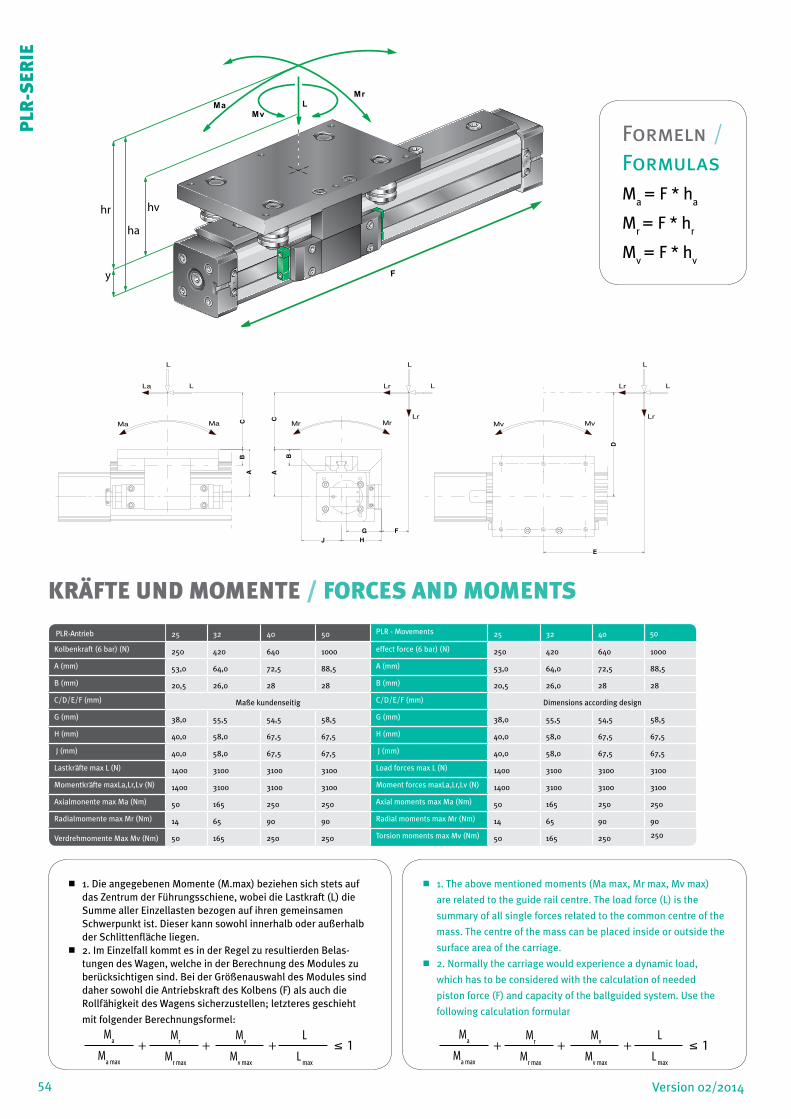
54 Version 02/2014
KRÄFTE UND MOMENTE / FORCES AND MOMENTS
PLR-Antrieb 25 32 40 50 PLR - Movements 25 32 40 50
Kolbenkraft (6 bar) (N) 250 420 640 1000 effect force (6 bar) (N) 250 420 640 1000
A (mm) 53,0 64,0 72,5 88,5 A (mm) 53,0 64,0 72,5 88,5
B (mm) 20,5 26,0 28 28 B (mm) 20,5 26,0 28 28
C/D/E/F (mm) Maße kundenseitig C/D/E/F (mm) Dimensions according design
G (mm) 38,0 55,5 54,5 58,5 G (mm) 38,0 55,5 54,5 58,5
H (mm) 40,0 58,0 67,5 67,5 H (mm) 40,0 58,0 67,5 67,5
J (mm) 40,0 58,0 67,5 67,5 J (mm) 40,0 58,0 67,5 67,5
Lastkräfte max L (N) 1400 3100 3100 3100 Load forces max L (N) 1400 3100 3100 3100
Momentkräfte maxLa,Lr,Lv (N) 1400 3100 3100 3100 Moment forces maxLa,Lr,Lv (N) 1400 3100 3100 3100
Axialmonente max Ma (Nm) 50 165 250 250 Axial moments max Ma (Nm) 50 165 250 250
Radialmomente max Mr (Nm) 14 65 90 90 Radial moments max Mr (Nm) 14 65 90 90
Verdrehmomente Max Mv (Nm) 50 165 250 250 Torsion moments max Mv (Nm) 50 165 250 250
CA
Ma Ma
La L
L
CB
A
Lr L
L
Lr
B
Lr L
L
Lr
D
Mv Mv
E
G FHJ
Mr Mr
1. Die angegebenen Momente (M.max) beziehen sich stets auf das Zentrum der Führungsschiene, wobei die Lastkraft (L) die Summe aller Einzellasten bezogen auf ihren gemeinsamen Schwerpunkt ist. Dieser kann sowohl innerhalb oder außerhalb der Schlittenfläche liegen.
2. Im Einzelfall kommt es in der Regel zu resultierden Belas-tungen des Wagen, welche in der Berechnung des Modules zu berücksichtigen sind. Bei der Größenauswahl des Modules sind daher sowohl die Antriebskraft des Kolbens (F) als auch die Rollfähigkeit des Wagens sicherzustellen; letzteres geschieht
mit folgender Berechnungsformel:
1. The above mentioned moments (Ma max, Mr max, Mv max)
are related to the guide rail centre. The load force (L) is the
summary of all single forces related to the common centre of the
mass. The centre of the mass can be placed inside or outside the
surface area of the carriage.
2. Normally the carriage would experience a dynamic load,
which has to be considered with the calculation of needed
piston force (F) and capacity of the ballguided system. Use the
following calculation formular
L
Mv
Ma
Mr
F
ha
y
hr hv
PLR
-SER
IE
Ma
Ma max
+ + + 1 Mr
Mr max
Mv
Mv max
L
L max
Ma
Ma max
+ + + 1 Mr
Mr max
Mv
Mv max
L
L max
Formeln / FormulasM
a = F * h
a
Mr = F * h
r
Mv = F * h
v

55Version 02/2014
STÜTZLÄNGENDIAGRAMM / DEFLECTION DIAGRAM
max. erlaubte Stützweite für PLR - Serie 25 - 40 mmmax. distance (SL) in m – for PLR-Series 25 - 40 mm
0
500
1000
1500
2000
2500
3000
3500
0,3 0,5 0,7 0,9 1,1 1,3 1,5 1,7 1,9 2,1 2,3 2,5
Stützlänge / distance SL (m)
Last
/ lo
ad L
(F) PLR25/25 Fall 1
PLR25/25 Fall 2PLR32/44 Fall 1PLR32/44 Fall 2PLR40/60 Fall 1PLR40/60 Fall 2
Fall 2Fall 1
F F
L
SL SL
L
SL
Typen Ident.-Nr. Ausführungen Types Ident.-No. Description
PLR25.1/25 32.525.• • • • Standard PLR25 mit Rollen-führung Größe 25
PLR25.1/25 32.525.• • • • Standard PLR25 with roller guide size 25
PLR25.1/44 32.544.• • • • Standard PLR25 mit Rollen-führung Größe 44
PLR25.1/44 32.544.• • • • Standard PLR25 with roller guide size44
PLR32.1/44 33.244.• • • • Standard PLR32 mit Rollen-führung Größe 44
PLR32.1/44 33.244.• • • • Standard PLR32 with roller guide size 44
PLR40.1/60 34.060.• • • • Standard PLR40 mit Rollen-führung Größe 60
PLR40.1/60 34.060.• • • • Standard PLR40 with roller guide size 60
PLR50.1/60 35.060.• • • • Standard PLR50 mit Rollen-führung Größe 60
PLR50.1/60 35.060.• • • • Standard PLR50 with roller guide size 60
PLR50.1/76 35.076.• • • • Standard PLR50 mit Rollen-führung Größe 76
PLR50.1/76 35.076.• • • • Standard PLR50 with roller guide size 76
PLR63.1/120 36.320.• • • • Standard PLR63 mit Rollen-führung Größe 120
PLR63.1/120 36.320.• • • • Standart PLR63 with rollerguide size 120
LINEARMODUL PLR / LINEAR UNIT PLR • • • • Stellenangaben bei Hubfestlegung ( 0100-5700 mm )• • • • Ident-figures forvstroke defenition ( 0100-5700 mm )
PLR
-SER
IE
Diagramm-Information:
Rechnerische Durchbiegungen ohne Unterstützung von 0,5 – 1mm
ermöglichen größere Stützlänge.
Rechnerische Durchbiegungen ohne Unterstützung von 1 – max.
1,5mm erfordern geringere Stützlänge.
Diagram Information:
Calculated deflections without support of 0,5 – 1mm allow
exceeding of supporting distance.
Calculated deflections without support of 1mm – max 1,5mm
require reduction of the supporting distance.
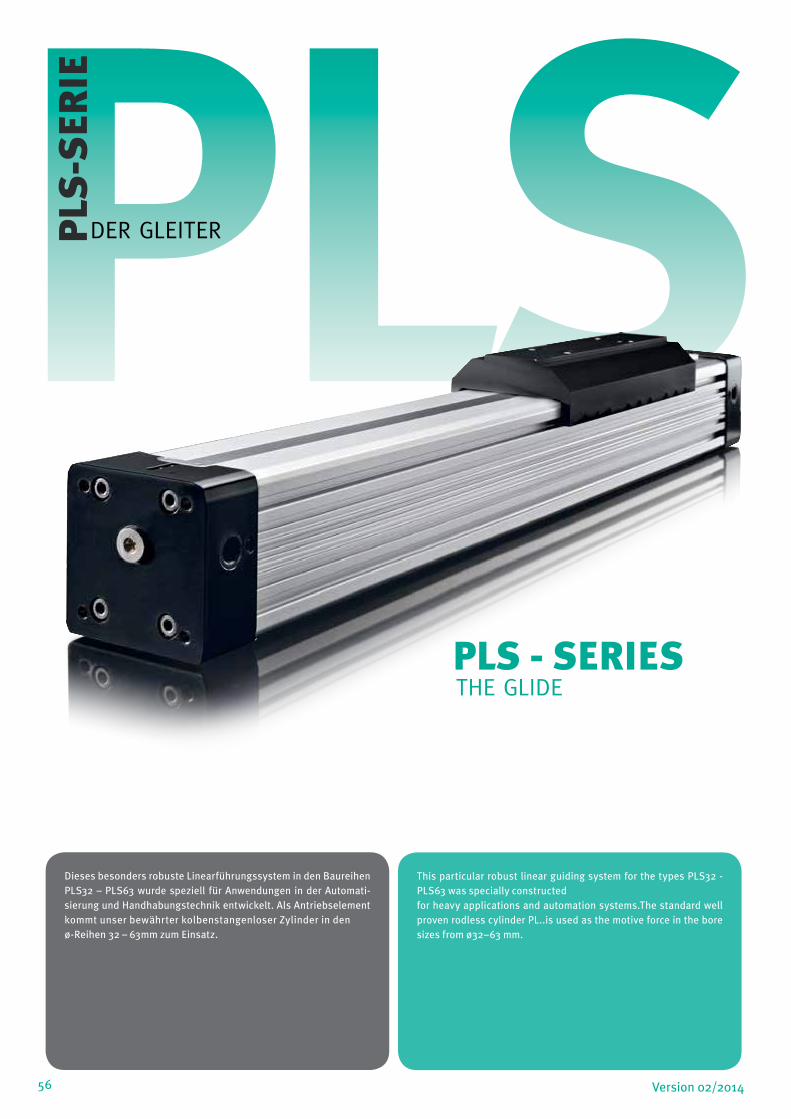
56 Version 02/2014
PLSPLS
-SER
IE
Dieses besonders robuste Linearführungssystem in den Baureihen PLS32 – PLS63 wurde speziell für Anwendungen in der Automati-sierung und Handhabungstechnik entwickelt. Als Antriebselement kommt unser bewährter kolbenstangenloser Zylinder in den ø-Reihen 32 – 63mm zum Einsatz.
This particular robust linear guiding system for the types PLS32 - PLS63 was specially constructedfor heavy applications and automation systems.The standard well proven rodless cylinder PL..is used as the motive force in the bore sizes from ø32–63 mm.
PLS - SERIES THE GLIDE
DER GLEITER
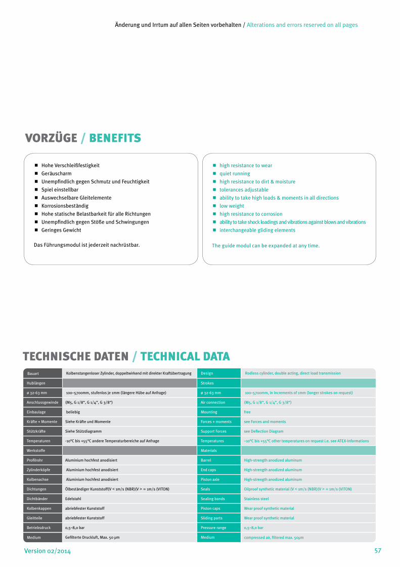
Änderung und Irrtum auf allen Seiten vorbehalten / Alterations and errors reserved on all pages
57Version 02/2014
Hohe Verschleißfestigkeit
Geräuscharm
Unempfindlich gegen Schmutz und Feuchtigkeit
Spiel einstellbar
Auswechselbare Gleitelemente
Korrosionsbeständig
Hohe statische Belastbarkeit für alle Richtungen
Unempfindlich gegen Stöße und Schwingungen
Geringes Gewicht
Das Führungsmodul ist jederzeit nachrüstbar.
high resistance to wear
quiet running
high resistance to dirt & moisture
tolerances adjustable
ability to take high loads & moments in all directions
low weight
high resistance to corrosion
ability to take shock loadings and vibrations against blows and vibrations
interchangeable gliding elements
The guide modul can be expanded at any time.
VORZÜGE / BENEFITS
TECHNISCHE DATEN / TECHNICAL DATABauart Kolbenstangenloser Zylinder, doppeltwirkend mit direkter Kraftübertragung Design Rodless cylinder, double acting, direct load transmission
Hublängen Strokes
ø 32-63 mm 100–5700mm, stufenlos je 1mm (längere Hübe auf Anfrage) ø 32-63 mm 100–5700mm, in increments of 1mm (longer strokes on request)
Anschlussgewinde (M5, G 1/8“, G 1/4“, G 3/8“) Air connection (M5, G 1/8“, G 1/4“, G 3/8“)
Einbaulage beliebig Mounting free
Kräfte + Momente Siehe Kräfte und Momente Forces + moments see Forces and moments
Stützkräfte Siehe Stützdiagramm Support Forces see Deflection Diagram
Temperaturen -10°C bis +55°C andere Temperaturbereiche auf Anfrage Temperatures –10°C bis +55°C other temperatures on request i.e. see ATEX-Informations
Werkstoffe Materials
Profilrohr Aluminium hochfest anodisiert Barrel High-strength anodized aluminum
Zylinderköpfe Aluminium hochfest anodisiert End caps High-strength anodized aluminum
Kolbenachse Aluminium hochfest anodisiert Piston axle High-strength anodized aluminum
Dichtungen Ölbeständiger Kunststoff(V < 1m/s (NBR)(V > = 1m/s (VITON) Seals Oilproof synthetic material (V < 1m/s (NBR)(V > = 1m/s (VITON)
Dichtbänder Edelstahl Sealing bands Stainless steel
Kolbenkappen abriebfester Kunststoff Piston caps Wear proof synthetic material
Gleitteile abriebfester Kunststoff Sliding parts Wear proof synthetic material
Betriebsdruck 0,5–8,0 bar Pressure range 0,5–8,0 bar
Medium Gefilterte Druckluft, Max. 50 µm Medium compressed air, filtered max. 50µm

58 Version 02/2014
System A B C D E E1 F G H K L M N M1 N1 P P1
PLS32 125 22 27 152 60 120 25 1/4 2,0 42,5 10,5 M5 10 M6 14 81,5 6,5
PLS40 150 12,5 30 215 68 160 25 1/4 7,0 44 15 M8 10 M6 17 97,5 6,5
PLS50 175 17,5 33 250 84 190 25 1/4 0,5 48,5 11,7 M8 10 M6 18 110 6,5
PLS63 215 6,5 55 320 120 240 25 3/8 1,5 56 25 M8 14 M8 18 137 5,0
DIMENSIONEN / DIMENSIONS
A
B
E
E1
F
M, N
WS
P1
H
Q1
Q
D
L
ZV
S
2xA + Hub 0,5
M, N M, N M, N
C
A
B
E
E1
F
M, N
WS
P1
H
Q1
Q
D
L
ZV
S
2xA + Hub 0,5
M, N M, N M, N
C
S1
WH
F
S
WS
W
P1
P
K
M
N
L
VH
G
ZV
S
M1,N1
System Q x Q1 S S1 VH VS W WH WS Z
PLS32 52 x 51 66 40 36 40 30 52 56 8
PLS40 58,5 x 59 79 45 54 54 36 72 69 9
PLS50 77 x 78 92 50 70 70 43,5 80 80 4
PLS63 102 x 102 116 50 78 78 62,5 106 106 14,5
PLS
-SER
IE

59Version 02/2014
1. Die angegebenen Momente (M.max) beziehen sich stets auf das Zentrum der Führungsschiene, wobei die Lastkraft (L) die Summe aller Einzellasten bezogen auf ihren gemeinsamen Schwerpunkt ist. Dieser kann sowohl innerhalb oder außerhalb der Schlittenfläche liegen.
2. Im Einzelfall kommt es in der Regel zu Resultierenden Belas-tungen des Wagen, welche in der Berechnung des Module zu berücksichtigen sind. Bei der Größenauswahl des Module sind dache sowohl die Antriebskraft (F) als auch die Rollfähigkeit des Wagens sicherzustellen; letzteres geschieht mit folgenden Berechnungsformel:
1. The above mentioned moments (Ma max, Mr max, Mv max) are
related to the guide rail centre. The load force (L) is the summary
of all single forces related to the common centre of the mass. The
centre of the mass can be placed inside or outside the surface
area of the carriage.
2. Normally the carriage would experience a dynamic load, which
has to be considered with the calculation of needed piston force
(F) and capacity of the guided system.
Use the following calculation formular:
BELASTUNGSWERTE PLS SERIE ø32-63 LOAD VALUES PLS SERIES Ø32 - 63
Kenndaten 32 40 50 63 Data 32 40 50 63
Kolbenkraft (6 bar) (N) 420 640 1000 1550 effect force (6 bar) (N) 420 640 1000 1550
Max. zul. Last L (N) 760 1330 1600 2770 Max. zul. Last L (N) 760 1330 1600 2770
Max. L a, L r, L v (N) 760 1330 1600 2770 Max. L a, L r, L v (N) 760 1330 1600 2770
Max. Ma (Nm) 39 99 170 315 Max. Ma (Nm) 39 99 170 315
Max. Mr (Nm) 15 35 58 105 Max. Mr (Nm) 15 35 58 105
Max Mv (Nm) 39 99 170 317 Max. Mv (Nm) 39 99 170 317
L
Mv
Ma Mr
F
ha
y
hr hv
Formeln / FormulasM
a = F * h
a
Mr = F * h
r
Mv = F * h
v
PLS
-SER
IE
Ma
Ma max
+ + + 1 Mr
Mr max
Mv
Mv max
L
L max
Ma
Ma max
+ + + 1 Mr
Mr max
Mv
Mv max
L
L max

60 Version 02/2014
max. erlaubte Stützweite für PLS - Serie 32 - 63 mmmax. distance (SL) in m – for PLS-Series 32 - 63 mm
0
500
1000
1500
2000
2500
3000
0,3
0,5
0,7
0,9
1,1
1,3
1,5
1,7
1,9
2,1
2,3
2,5
Stützlänge/distance SL (m)
Last
/ lo
ad L
(F=N
)
PLS32PLS40PLS50PLS63
L
SL SL
L
SL
STÜTZLÄNGENDIAGRAMM / DEFLECTION DIAGRAM
LINEARMODUL PLS / LINEAR UNIT PLS
Typen Ident.-Nr. Ausführungen Types Ident.-No. Description
PLS 32/00 93.277.• • • • Standard PLS32 mit externer Gleitführung
PLS 32/00 93.277.• • • • Standard PLS32 with externalgliding guide
PLS 40/00 94.077.• • • • Standard PLS40 mit externer Gleitführung
PLS 40/00 94.077.• • • • Standard PLS40 with externalgliding guide
PLS 50/00 95.077.• • • • Standard PLS50 mit externer Gleitführung
PLS 50/00 95.077.• • • • Standard PLS50 with externalgliding guide
PLS 63/00 96.377.• • • • Standard PLS63 mit externer Gleitführung
PLS 63/00 96.377.• • • • Standart PLS63 with externalgliding guide
• • • • Stellenangaben bei Hubfestlegung ( 0100-5700 mm )• • • • Ident-figures forvstroke defenition ( 0100-5700 mm )
PLS
-SER
IE
Diagramm-Information:
Rechnerische Durchbiegungen ohne Unterstützung von 0,5 – 1mm
ermöglichen größere Stützlänge.
Rechnerische Durchbiegungen ohne Unterstützung von 1 – max.
1,5mm erfordern geringere Stützlänge.
Diagram Information:
Calculated deflections without support of 0,5 – 1mm allow
exceeding of supporting distance.
Calculated deflections without support of 1mm – max 1,5mm
require reduction of the supporting distance.
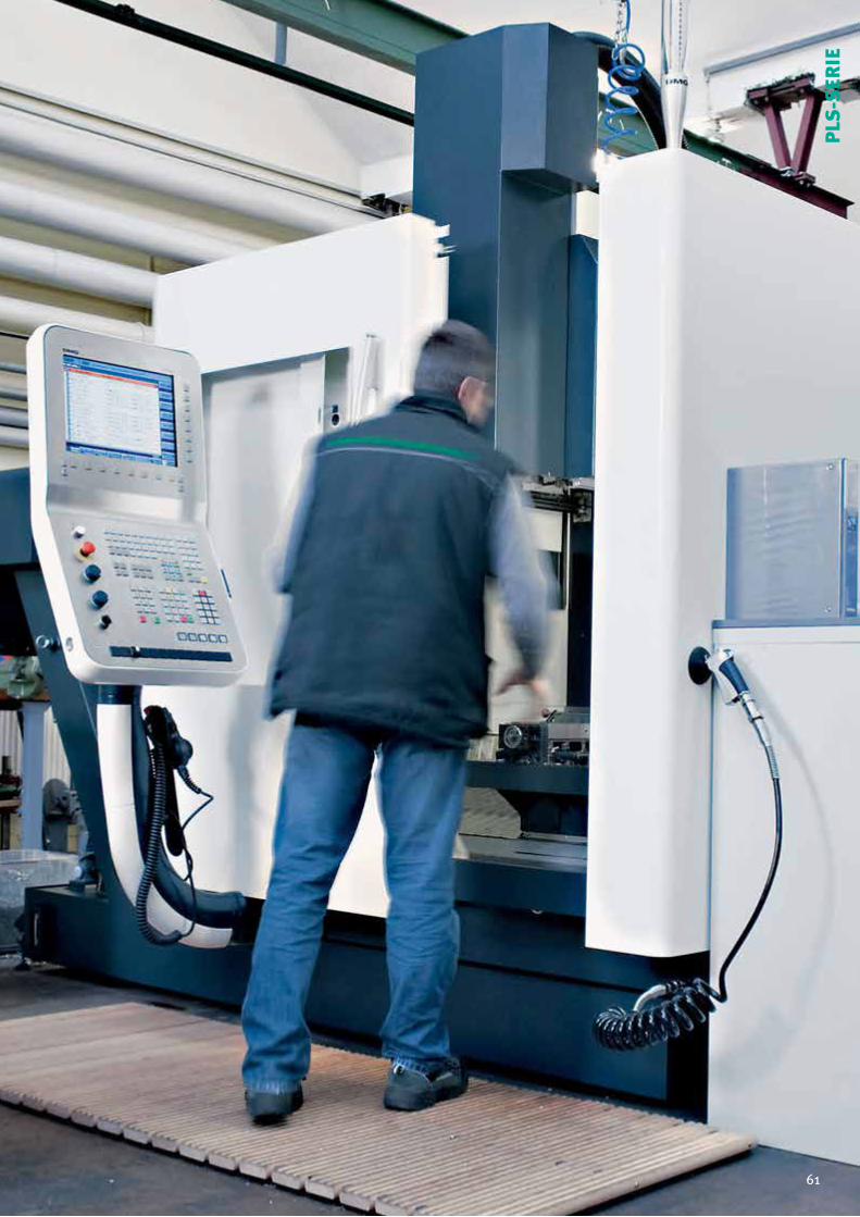
61Version 02/2014 61
PLS
-SER
IE
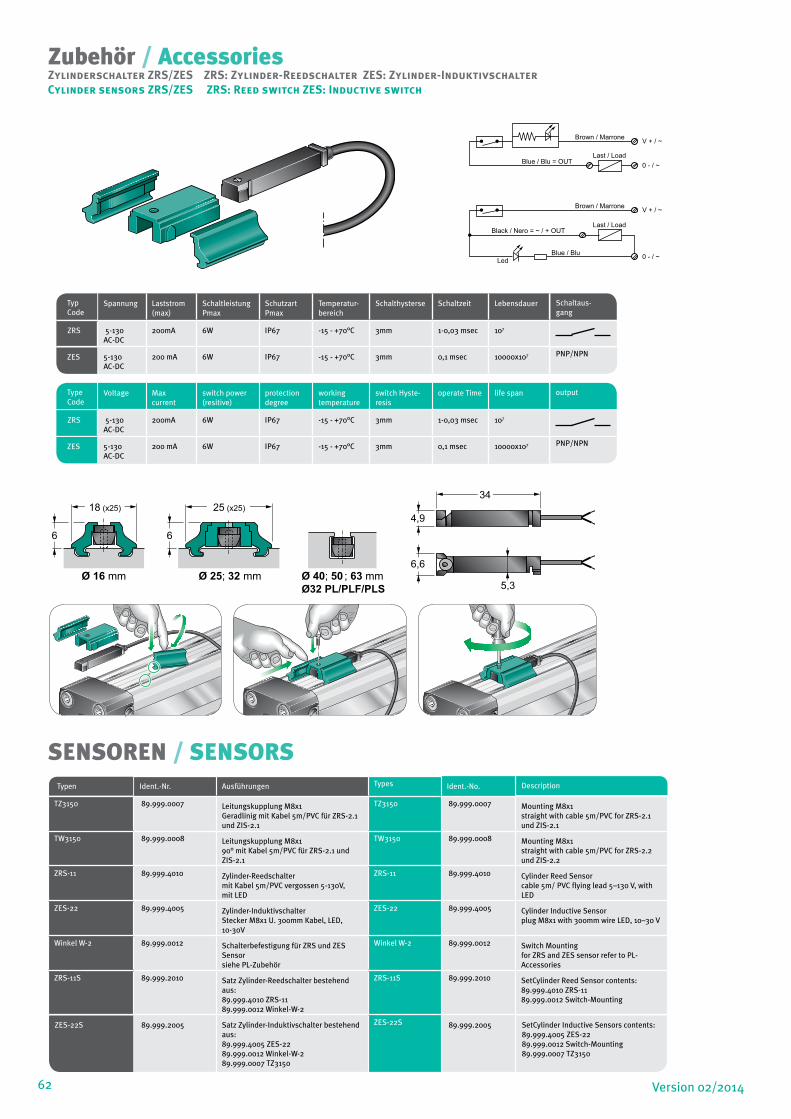
62 Version 02/2014
Zubehör / AccessoriesZylinderschalter ZRS/ZES ZRS: Zylinder-Reedschalter ZES: Zylinder-InduktivschalterCylinder sensors ZRS/ZES ZRS: Reed switch ZES: Inductive switch
Brown / Marrone V + / ~
0 - / ~Blue / Blu = OUTLast / Load
Brown / Marrone V + / ~
0 - / ~LedBlue / Blu
Black / Nero = ~ / + OUTLast / Load
Ø 16 mm Ø 40; 50 ; 63 mmØ 25; 32 mm
34
4,9
6,6
5,3
18 (x25) 25 (x25)
6 6
SENSOREN / SENSORSTypen
Ident.-Nr. Ausführungen Types Ident.-No. Description
TZ3150 89.999.0007 Leitungskupplung M8x1Geradlinig mit Kabel 5m/PVC für ZRS-2.1 und ZIS-2.1
TZ3150 89.999.0007 Mounting M8x1 straight with cable 5m/PVC for ZRS-2.1 und ZIS-2.1
TW3150 89.999.0008 Leitungskupplung M8x190° mit Kabel 5m/PVC für ZRS-2.1 und ZIS-2.1
TW3150 89.999.0008 Mounting M8x1 straight with cable 5m/PVC for ZRS-2.2 und ZIS-2.2
ZRS-11 89.999.4010 Zylinder-Reedschaltermit Kabel 5m/PVC vergossen 5-130V, mit LED
ZRS-11 89.999.4010 Cylinder Reed Sensorcable 5m/ PVC flying lead 5–130 V, with LED
ZES-22 89.999.4005 Zylinder-Induktivschalter Stecker M8x1 U. 300mm Kabel, LED, 10-30V
ZES-22 89.999.4005 Cylinder Inductive Sensorplug M8x1 with 300mm wire LED, 10–30 V
Winkel W-2 89.999.0012 Schalterbefestigung für ZRS und ZES Sensorsiehe PL-Zubehör
Winkel W-2 89.999.0012 Switch Mountingfor ZRS and ZES sensor refer to PL-Accessories
ZRS-11S 89.999.2010 Satz Zylinder-Reedschalter bestehend aus:89.999.4010 ZRS-1189.999.0012 Winkel-W-2
ZRS-11S 89.999.2010 SetCylinder Reed Sensor contents:89.999.4010 ZRS-1189.999.0012 Switch-Mounting
ZES-22S 89.999.2005 Satz Zylinder-Induktivschalter bestehend aus:89.999.4005 ZES-2289.999.0012 Winkel-W-289.999.0007 TZ3150
ZES-22S 89.999.2005 SetCylinder Inductive Sensors contents:89.999.4005 ZES-2289.999.0012 Switch-Mounting89.999.0007 TZ3150
Typ Code
Spannung Laststrom (max)
Schaltleistung Pmax
Schutzart Pmax
Temperatur-bereich
Schalthysterse Schaltzeit Lebensdauer Schaltaus- gang
ZRS 5-130 AC-DC
200mA 6W IP67 -15 - +70°C 3mm 1-0,03 msec 107
ZES 5-130 AC-DC
200 mA 6W IP67 -15 - +70°C 3mm 0,1 msec 10000x107 PNP/NPN
Type Code
Voltage Max current
switch power (resitive)
protection degree
working temperature
switch Hyste-resis
operate Time life span output
ZRS 5-130 AC-DC
200mA 6W IP67 -15 - +70°C 3mm 1-0,03 msec 107
ZES 5-130 AC-DC
200 mA 6W IP67 -15 - +70°C 3mm 0,1 msec 10000x107 PNP/NPN
Ø32 PL/PLF/PLS
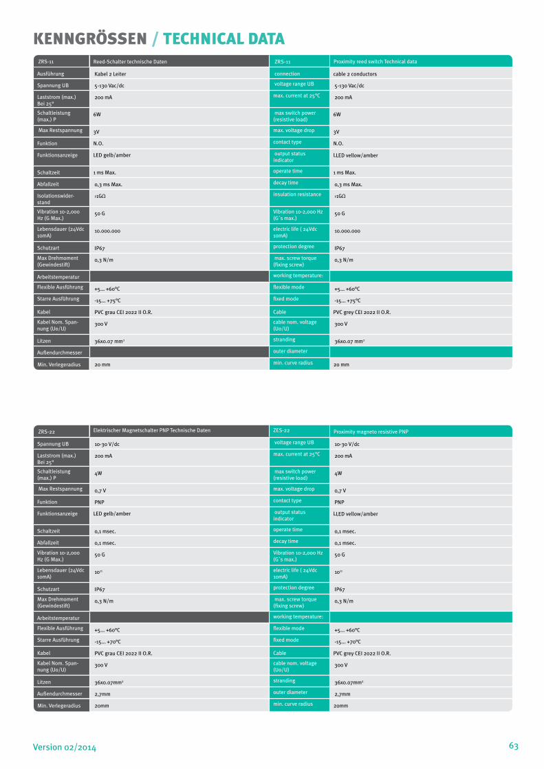
63Version 02/2014
KENNGRÖSSEN / TECHNICAL DATAZRS-11 Reed-Schalter technische Daten ZRS-11 Proximity reed switch Technical data
Ausführung Kabel 2 Leiter connection cable 2 conductors
Spannung UB 5-130 Vac/dc voltage range UB 5-130 Vac/dc
Laststrom (max.) Bei 25°
200 mA max. current at 25°C 200 mA
Schaltleistung (max.) P
6W max switch power (resistive load)
6W
Max Restspannung 3V max. voltage drop 3V
Funktion N.O. contact type N.O.
Funktionsanzeige LED gelb/amber output status indicator
LLED vellow/amber
Schaltzeit 1 ms Max. operate time 1 ms Max.
Abfallzeit 0,3 ms Max. decay time 0,3 ms Max.
Isolationswider-stand
›1GΩ insulation resistance ›1GΩ
Vibration 10-2,000 Hz (G Max.)
50 G Vibration 10-2,000 Hz (G´s max.)
50 G
Lebensdauer (24Vdc 10mA)
10.000.000 electric life ( 24Vdc 10mA)
10.000.000
Schutzart IP67 protection degree IP67
Max Drehmoment (Gewindestift)
0,3 N/m max. screw torque (fixing screw)
0,3 N/m
Arbeitstemperatur working temperature:
Flexible Ausführung +5... +60°C flexible mode +5... +60°C
Starre Ausführung -15... +75°C fixed mode -15... +75°C
Kabel PVC grau CEI 2022 II O.R. Cable PVC grey CEI 2022 II O.R.
Kabel Nom. Span-nung (Uo/U)
300 V cable nom. voltage (Uo/U)
300 V
Litzen 36x0.07 mm2 stranding 36x0.07 mm2
Außendurchmesser outer diameter
Min. Verlegeradius 20 mm min. curve radius 20 mm
ZRS-22 Elektrischer Magnetschalter PNP Technische Daten ZES-22 Proximity magneto resistive PNP
Spannung UB 10-30 V/dc voltage range UB 10-30 V/dc
Laststrom (max.) Bei 25°
200 mA max. current at 25°C 200 mA
Schaltleistung (max.) P
4W max switch power (resistive load)
4W
Max Restspannung 0,7 V max. voltage drop 0,7 V
Funktion PNP contact type PNP
Funktionsanzeige LED gelb/amber output status indicator
LLED vellow/amber
Schaltzeit 0,1 msec. operate time 0,1 msec.
Abfallzeit 0,1 msec. decay time 0,1 msec.
Vibration 10-2,000 Hz (G Max.)
50 G Vibration 10-2,000 Hz (G´s max.)
50 G
Lebensdauer (24Vdc 10mA)
1011 electric life ( 24Vdc 10mA)
1011
Schutzart IP67 protection degree IP67
Max Drehmoment (Gewindestift)
0,3 N/m max. screw torque (fixing screw)
0,3 N/m
Arbeitstemperatur working temperature:
Flexible Ausführung +5... +60°C flexible mode +5... +60°C
Starre Ausführung -15... +70°C fixed mode -15... +70°C
Kabel PVC grau CEI 2022 II O.R. Cable PVC grey CEI 2022 II O.R.
Kabel Nom. Span-nung (Uo/U)
300 V cable nom. voltage (Uo/U)
300 V
Litzen 36x0.07mm2 stranding 36x0.07mm2
Außendurchmesser 2,7mm outer diameter 2,7mm
Min. Verlegeradius 20mm min. curve radius 20mm
64 Version 02/201464


MEDAN GmbHAuf dem Brühl 6D-72658 Bempflingen
Phone: +49 (7123) 32402Fax: +49 (7123) 36580Email: [email protected] Au
flag
e 1/
2013
© M
edan
Gm
bH
Medan WeltweitMedan World Wide
Benelux
Benelux
Bulgarien
Bulgaria
China
China
Dänemark
Denmark
Deutschland
Germany
El Salvador
El Salvador
Finnland
Finland
Frankreich
FranceGroßbritannien
Great Britain
Indien
India
Indonesien
Indonesia
Iran
Iran
Irland
Ireland
Israel
Israel
Kanada
Canada
Korea
Korea
Litauen
Lithuania
Malaysia
Malaysia
Norwegen
Norway
Österreich
AustriaItalien
Italy
Polen
PolandPortugal
Portugal
Rumänien
Romania
Schweden
Sweden
Schweiz
Switzerland
Singapur
Singapoor
Slowenien
Slowenia
Südafrika
South Africa
Thailand
Thailand
Türkei
Turkey
Ungarn
Hungaria
Spanien
Spain
With partners located all over the World we provide the service and consultants of our product range in various languages.