
MEDAN Prod-Kat U1 neu 9-08.qxd 17.09.2008 9:27 Uhr Seite U-1 · Zu diesem Katalog Das Programm der...
44
Linearzylinder Pneumatic Cylinder Vérins pneumatiques
Transcript of MEDAN Prod-Kat U1 neu 9-08.qxd 17.09.2008 9:27 Uhr Seite U-1 · Zu diesem Katalog Das Programm der...
Linearzylinder
Pneumatic Cylinder
Vérins pneumatiques
MEDAN_Prod-Kat_U1_neu 9-08.qxd 17.09.2008 9:27 Uhr Seite U-1
Zu diesem KatalogDas Programm der MEDAN-Kolbenstangenlosen Zylinder wird ständig erweitert – der Katalog entspricht dem aktuellen Entwicklungsstand.
Da die MEDAN GMBH ständig nach den modernsten Arbeitsmethoden fertigen, prüfen und verbessern lässt, behält sich diese zum Zweckeder Weiterentwicklung ausdrücklich das Recht auf Änderung vor.Die Veröffentlichung dieses Kataloges erfolgt ohne Gewähr für eventuelle Druckfehler oder Irrtümer. Mit Erscheinen dieses Kataloges verlie-ren alle bisherigen Kataloge ihre Gültigkeit.
About this catalogueThe program of the MEDAN cylinder is in a steady development – this catalogue is corresponding to the present developing situation.
MEDAN GMBH is committed to a very high standard of manufacturing, inspection, testing and improving. Therefore we reserve the right tomake occasional changes. The publishing of this catalogue goes along without any obligations in regards of any misprints or mistakes. All pre-vious catalogues loose their legal validity.
Ce catalogueLa gamme de vérins sans tige „MEDAN“ se trouve en constante évolution.
Comme la MEDAN GMBH fabrique, contrôle et améliore en permanence ses produits selon les procédés les plus modernes, elle se réserveexpressément le droit de changer de se produits afin de les faire évoluer.Ce catalogue annulé la validité des catalogues précédents.
© MEDAN GmbH, Auf dem Brühl 6, 72658 Bempflingen. All rights Febr. 2009
Änderung und Irrtum auf allen Seiten vorbehalten / Alterations and errors reserved on all pages / Document non contractuel
Medan-Katalog_neu_2-2009.qxd 26.02.2009 16:41 Uhr Seite U2
D
E
C
B
A
1
Inhaltsverzeichnis – Contents – Table des matieres
Druckluftzylinder – PL + PLF- kolbenstangenlos / Pneumatic cylinder – PL + PLF- rodless /
Vérin pneumatique – Série PL + PLF- sans tige
Vorstellung / Introduction / PrésentationTechnische Daten / Technical Datas / Caractéristiques techniquesZylinderbefestigungen / Cylinder mountings / Fixations Lastbefestigungen / Load mountings / Portes-chargesSensoren / Sensors / Détecteurs
Druckluftzylinder – DUO 96 / Pneumatic cylinder – DUO 96 / Vérin pneumatique – DUO 96
Vorstellung / Introduction / Présentation
Technische Daten / Technical Datas / Caractéristiques techniques
Zylinderbefestigungen / Cylinder mountings / Fixations
Gleitwagen-System – Gliding carriage-system – Système avec un chariot à patins
Technische Beschreibung / Technical description / Description technique
PLG
Linearführung – Linear Guide – Guidage linéaire
Technische Beschreibung / Technical description / Description technique
PLK
Bestellinformationen – Ordering instructions – Informations pour commander
Zubehör / Accessories / Accessoires
A
B
C
D
E
Medan-Katalog_neu_2-2009.qxd 26.02.2009 16:41 Uhr Seite 1
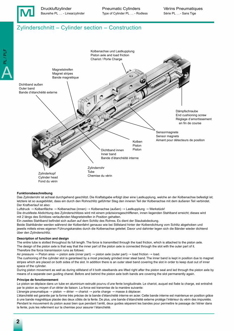
Zylinderschnitt – Cylinder section – Construction
FunktionsbeschreibungDas Zylinderrohr ist achsial durchgehend geschlitzt. Die Kraftabgabe erfolgt über eine Lastkupplung, welche an der Kolbenachse befestigt ist;letztere ist so ausgebildet, dass ein durch den Rohrschlitz geführter Steg den inneren Teil der Kolbenachse mit dem äußeren Teil verbindet.Der Kraftverlauf ist also:Luftdruck → Kolbenfläche → Kolbenachse (innen) → Kolbenachse (außen) → Lastkupplung → Werkstück!Die druckfeste Abdichtung des Zylinderschlitzes wird mit einem präzisionsgeschliffenen, innen liegenden Stahlband erreicht; dieses wird mit 2 längs des Schlitzes verlaufenden Magnetstreifen in Position gehalten.Ein zweites Stahlband befindet sich außen auf dem Schlitz des Rohres. Es dient der Staubabdeckung.Beide Stahlbänder werden während der Kolbenfahrt genauso wie bei Stillstand hinter der Kolbendichtung vom Schlitz abgehoben undjeweils mittels eines eigenen Führungskanales durch die Kolbenachse geleitet. Davor und dahinter legen sich die Bänder wieder dichtendüber den Zylinderschlitz.
Description of function and designThe entire tube is slotted throughout its full length. The force is transmitted through the load friction, which is attached to the piston axle.The design of the piston axle is that way that the inner part of the piston axle is connected through the slot with the outer part of it.Therefore the force transmission runs as follows:Air pressure → Piston area → piston axle (inner part) → piston axle (outer part) → load friction → load.The cushioning of the cylinder slot is garanteed by a most precisely grinded inner steel band. The inner band is kept in position due to magnetstripes which are placed on both sides of the slot. In addition there is an outer steel band covering the slot in order to keep dust out of innerspace of the cylinder.During piston movement as well as during stillstand of it both steelbands are lifted right after the piston seal and led through the piston axle bymeans of a separate own guiding chanel. Before and behind the piston axle both bands are covering the slot permanently again.
Principe de fonctionnementLe piston se déplace dans un tube en aluminium extrudé pourvu d’une fente longitudinale. Le chariot, auquel est fixée la charge, est entraînépar le piston au moyen d’un étrier de liaison. La force est transmise de la manière suivante:L’énergie pneumatique → piston → étrier → chariot → porte charge → masse à déplacer.L’étanchéité est garantie par la forme très précise de la bande d’étanchéité interne en acier. Cette bande interne est maintenue en position grâceà une bande magnétique placée des deux côtés de la fente. De plus, une bande d’étanchéité externe protège l’intérieur du vérin des impuretés.Pendant le mouvement du piston aussi bien que pendant l’arrêt, deux guides séparent les bandes pour permettre le passage de l’étrier dansla fente, puis les referment sur la chemise pour assurer l’étanchéité.
22
Kolbenachse und LastkupplungPiston axle and load frictionChariot / Porte Charge
MagnetstreifenMagnet stripesBande magnétique
Dichtband außenOuter bandBande d’étanchéité externe
ZylinderkopfCylinder headFond du vérin
Dichtband innenInner bandBande d’étanchéité interne
SensormagneteSensor magnetsAimant pour détecteurs de position
DämpfschraubeEnd cushioning screwRéglage d’amortissement
en fin de course
KolbenPistonPiston
ZylinderrohrTubeChemise du vérin
Druckluftzylinder Pneumatic Cylinders Vérins PneumatiquesBaureihe PL … - Linearzylinder Type of Cylinder PL … - Rodless Série PL …- Sans Tige
A
PL
/ PLF
Medan-Katalog_neu_2-2009.qxd 26.02.2009 16:41 Uhr Seite 2
3
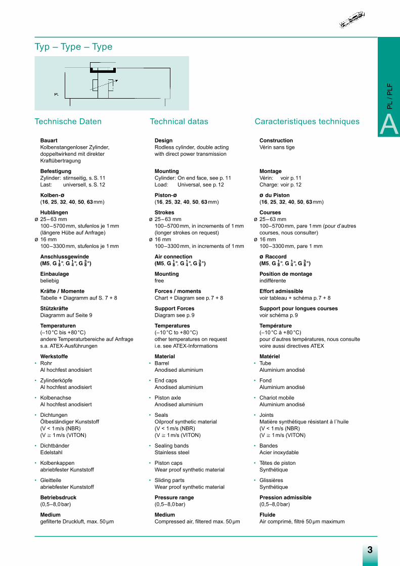
Technische Daten
BauartKolbenstangenloser Zylinder, doppeltwirkend mit direkter Kraftübertragung
BefestigungZylinder: stirnseitig, s.S.11Last: universell, s.S.12
Kolben-ø(16, 25, 32, 40, 50, 63mm)
Hublängenø 25– 63 mm
100–5700mm, stufenlos je 1mm(längere Hübe auf Anfrage)
ø 16 mm100–3300mm, stufenlos je 1mm
Anschlussgewinde(M5, G 1
8", G 14", G 3
8")
Einbaulagebeliebig
Kräfte / MomenteTabelle + Diagramm auf S. 7 + 8
StützkräfteDiagramm auf Seite 9
Temperaturen(–10°C bis +80°C)andere Temperaturbereiche auf Anfrages.a. ATEX-Ausführungen
Werkstoffe• Rohr
Al hochfest anodisiert
• ZylinderköpfeAl hochfest anodisiert
• KolbenachseAl hochfest anodisiert
• DichtungenÖlbeständiger Kunststoff(V < 1m/s (NBR)(V � 1m/s (VITON)
• DichtbänderEdelstahl
• Kolbenkappenabriebfester Kunststoff
• Gleitteileabriebfester Kunststoff
Betriebsdruck(0,5–8,0bar)
Mediumgefilterte Druckluft, max. 50µm
Technical datas
DesignRodless cylinder, double acting with direct power transmission
MountingCylinder: On end face, see p. 11Load: Universal, see p.12
Piston-ø(16, 25, 32, 40, 50, 63mm)
Strokesø 25– 63 mm
100–5700mm, in increments of 1mm(longer strokes on request)
ø 16 mm100–3300mm, in increments of 1mm
Air connection(M5, G 1
8", G 14", G 3
8")
Mountingfree
Forces / momentsChart + Diagram see p.7 + 8
Support ForcesDiagram see p.9
Temperatures(–10°C to +80°C)other temperatures on requesti.e. see ATEX-Informations
Material• Barrel
Anodised aluminium
• End capsAnodised aluminium
• Piston axleAnodised aluminium
• SealsOilproof synthetic material(V < 1m/s (NBR)(V � 1m/s (VITON)
• Sealing bandsStainless steel
• Piston capsWear proof synthetic material
• Sliding partsWear proof synthetic material
Pressure range(0,5–8,0bar)
MediumCompressed air, filtered max. 50µm
Caracteristiques techniques
ConstructionVérin sans tige
MontageVérin: voir p.11Charge: voir p.12
ø du Piston(16, 25, 32, 40, 50, 63mm)
Coursesø 25– 63 mm
100–5700mm, pare 1mm (pour d’autrescourses, nous consulter)
ø 16 mm100–3300mm, pare 1 mm
ø Raccord(M5, G 1
8", G 14", G 3
8")
Position de montageindifférente
Effort admissiblevoir tableau + schéma p.7 + 8
Support pour longues coursesvoir schéma p.9
Température(–10°C à +80°C)pour d’autres températures, nous consultevoire aussi directives ATEX
Matériel• Tube
Aluminium anodisé
• FondAluminium anodisé
• Chariot mobileAluminium anodisé
• JointsMatière synthétique résistant à l`huile(V < 1m/s (NBR)(V � 1m/s (VITON)
• BandesAcier inoxydable
• Têtes de pistonSynthétique
• GlissièresSynthétique
Pression admissible(0,5–8,0bar)
FluideAir comprimé, filtré 50µm maximum
Typ – Type – Type
A
PL
/ PLF
Medan-Katalog_neu_2-2009.qxd 26.02.2009 16:42 Uhr Seite 3
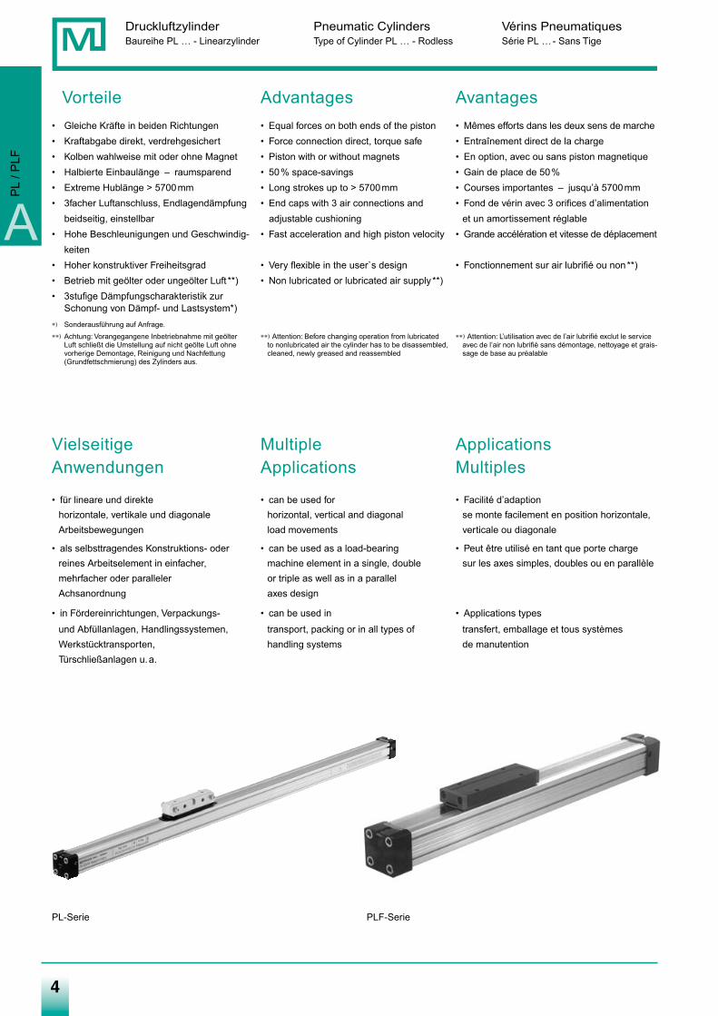
Vorteile Advantages Avantages• Gleiche Kräfte in beiden Richtungen • Equal forces on both ends of the piston • Mêmes efforts dans les deux sens de marche• Kraftabgabe direkt, verdrehgesichert • Force connection direct, torque safe • Entraînement direct de la charge• Kolben wahlweise mit oder ohne Magnet • Piston with or without magnets • En option, avec ou sans piston magnetique• Halbierte Einbaulänge – raumsparend • 50% space-savings • Gain de place de 50%• Extreme Hublänge > 5700mm • Long strokes up to > 5700mm • Courses importantes – jusqu’à 5700mm• 3facher Luftanschluss, Endlagendämpfung • End caps with 3 air connections and • Fond de vérin avec 3 orifices d’alimentation
beidseitig, einstellbar adjustable cushioning et un amortissement réglable• Hohe Beschleunigungen und Geschwindig- • Fast acceleration and high piston velocity • Grande accélération et vitesse de déplacement
keiten• Hoher konstruktiver Freiheitsgrad • Very flexible in the user`s design • Fonctionnement sur air lubrifié ou non**)• Betrieb mit geölter oder ungeölter Luft **) • Non lubricated or lubricated air supply **)• 3stufige Dämpfungscharakteristik zur
Schonung von Dämpf- und Lastsystem*)∗) Sonderausführung auf Anfrage.∗∗) Achtung: Vorangegangene Inbetriebnahme mit geölter ∗∗) Attention: Before changing operation from lubricated ∗∗) Attention: L’utilisation avec de l’air lubrifié exclut le service
Luft schließt die Umstellung auf nicht geölte Luft ohne to nonlubricated air the cylinder has to be disassembled, avec de l’air non lubrifié sans démontage, nettoyage et grais-vorherige Demontage, Reinigung und Nachfettung cleaned, newly greased and reassembled sage de base au préalable(Grundfettschmierung) des Zylinders aus.
Vielseitige Multiple ApplicationsAnwendungen Applications Multiples
• für lineare und direkte • can be used for • Facilité d’adaptionhorizontale, vertikale und diagonale horizontal, vertical and diagonal se monte facilement en position horizontale,Arbeitsbewegungen load movements verticale ou diagonale
• als selbsttragendes Konstruktions- oder • can be used as a load-bearing • Peut être utilisé en tant que porte chargereines Arbeitselement in einfacher, machine element in a single, double sur les axes simples, doubles ou en parallèlemehrfacher oder paralleler or triple as well as in a parallelAchsanordnung axes design
• in Fördereinrichtungen, Verpackungs- • can be used in • Applications types
und Abfüllanlagen, Handlingssystemen, transport, packing or in all types of transfert, emballage et tous systèmesWerkstücktransporten, handling systems de manutentionTürschließanlagen u.a.
44
Druckluftzylinder Pneumatic Cylinders Vérins PneumatiquesBaureihe PL … - Linearzylinder Type of Cylinder PL … - Rodless Série PL …- Sans Tige
A
PL
/ PLF
PLF-SeriePL-Serie
Medan-Katalog_neu_2-2009.qxd 26.02.2009 16:42 Uhr Seite 4
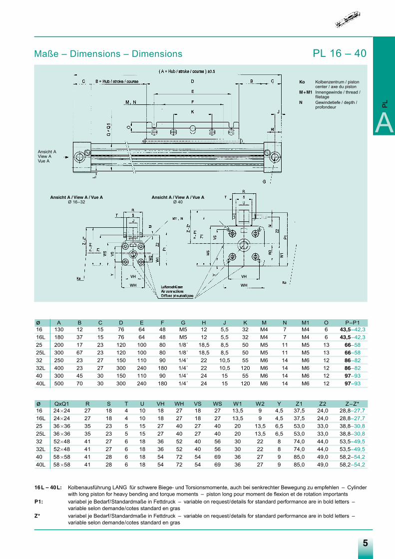
Maße – Dimensions – Dimensions PL 16 – 40
5
Ko Kolbenzentrum / pistoncenter / axe du piston
M+M1 Innengewinde / thread /filetage
N Gewindetiefe / depth /profondeur
Ansicht A / View A / Vue AØ 16–32
Ansicht A / View A / Vue AØ 40
A
PL
Ansicht AView AVue A
ø A B C D E F G H J K M N M1 O P–P116 130 12 15 76 64 48 M5 12 5,5 32 M4 7 M4 6 43,5–42,316L 180 37 15 76 64 48 M5 12 5,5 32 M4 7 M4 6 43,5–42,325 200 17 23 120 100 80 1/8´ 18,5 8,5 50 M5 11 M5 13 66–5825L 300 67 23 120 100 80 1/8´ 18,5 8,5 50 M5 11 M5 13 66–5832 250 23 27 150 110 90 1/4´ 22 10,5 55 M6 14 M6 12 86–8232L 400 23 27 300 240 180 1/4´ 22 10,5 120 M6 14 M6 12 86–8240 300 45 30 150 110 90 1/4´ 24 15 55 M6 14 M6 12 97–9340L 500 70 30 300 240 180 1/4´ 24 15 120 M6 14 M6 12 97–93
ø QxQ1 R S T U VH WH VS WS W1 W2 Y Z1 Z2 Z–Z*16 24�24 27 18 4 10 18 27 18 27 13,5 9 4,5 37,5 24,0 28,8–27,716L 24�24 27 18 4 10 18 27 18 27 13,5 9 4,5 37,5 24,0 28,8–27,725 36�36 35 23 5 15 27 40 27 40 20 13,5 6,5 53,0 33,0 38,8–30,825L 36�36 35 23 5 15 27 40 27 40 20 13,5 6,5 53,0 33,0 38,8–30,832 52�48 41 27 6 18 36 52 40 56 30 22 8 74,0 44,0 53,5–49,532L 52�48 41 27 6 18 36 52 40 56 30 22 8 74,0 44,0 53,5–49,540 58�58 41 28 6 18 54 72 54 69 36 27 9 85,0 49,0 58,2–54,240L 58�58 41 28 6 18 54 72 54 69 36 27 9 85,0 49,0 58,2–54,2
16L – 40L: Kolbenausführung LANG für schwere Biege- und Torsionsmomente, auch bei senkrechter Bewegung zu empfehlen – Cylinderwith long piston for heavy bending and torque moments – piston long pour moment de flexion et de rotation importants
P1: variabel je Bedarf/Standardmaße in Fettdruck – variable on request/details for standard performance are in bold letters –variable selon demande/cotes standard en gras
Z* variabel je Bedarf/Standardmaße in Fettdruck – variable on request/details for standard performance are in bold letters –variable selon demande/cotes standard en gras
L
VH
WH
VH
WH
Medan-Katalog_neu_2-2009.qxd 26.02.2009 16:42 Uhr Seite 5
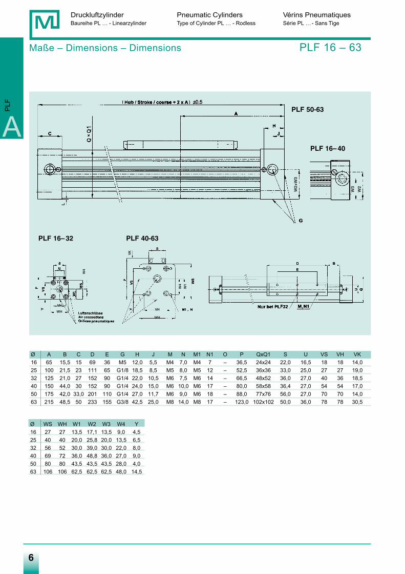
Ø A B C D E G H J M N M1 N1 O P QxQ1 S U VS VH VK16 65 15,5 15 69 36 M5 12,0 5,5 M4 7,0 M4 7 – 36,5 24x24 22,0 16,5 18 18 14,025 100 21,5 23 111 65 G1/8 18,5 8,5 M5 8,0 M5 12 – 52,5 36x36 33,0 25,0 27 27 19,032 125 21,0 27 152 90 G1/4 22,0 10,5 M6 7,5 M6 14 – 66,5 48x52 36,0 27,0 40 36 18,540 150 44,0 30 152 90 G1/4 24,0 15,0 M6 10,0 M6 17 – 80,0 58x58 36,4 27,0 54 54 17,050 175 42,0 33,0 201 110 G1/4 27,0 11,7 M6 9,0 M6 18 – 88,0 77x76 56,0 27,0 70 70 14,063 215 48,5 50 233 155 G3/8 42,5 25,0 M8 14,0 M8 17 – 123,0 102x102 50,0 36,0 78 78 30,5
Druckluftzylinder Pneumatic Cylinders Vérins PneumatiquesBaureihe PL … - Linearzylinder Type of Cylinder PL … - Rodless Série PL …- Sans Tige
6
Maße – Dimensions – Dimensions PLF 16 – 63
A
PLF
PLF 16– 40
PLF 50-63
PLF 16– 32 PLF 40-63
Ø WS WH W1 W2 W3 W4 Y16 27 27 13,5 17,1 13,5 9,0 4,525 40 40 20,0 25,8 20,0 13,5 6,532 56 52 30,0 39,0 30,0 22,0 8,040 69 72 36,0 48,8 36,0 27,0 9,050 80 80 43,5 43,5 43,5 28,0 4,063 106 106 62,5 62,5 62,5 48,0 14,5
L
VK
W2+
W3
W3
W2
VH
WHVH
WH
W4
W4
W1
Medan-Katalog_neu_2-2009.qxd 26.02.2009 16:42 Uhr Seite 6
7
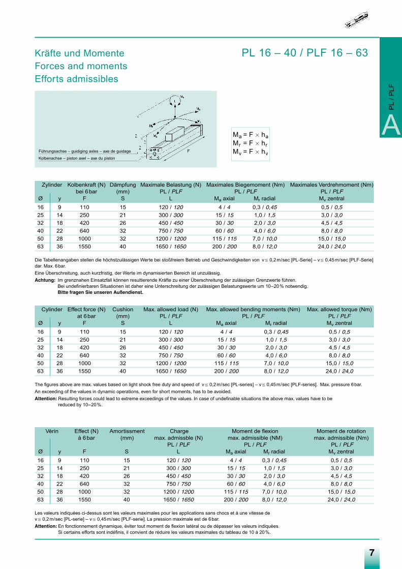
Ma = F � haMr = F � hrMv = F � hv
A
Kräfte und Momente PL 16 – 40 / PLF 16 – 63Forces and momentsEfforts admissibles
PL
/ PLF
Führungsachse – guidiging axles – axe de guidage
Kolbenachse – piston axel – axe du piston
Zylinder Kolbenkraft (N) Dämpfung Maximale Belastung (N) Maximales Biegemoment (Nm) Maximales Verdrehmoment (Nm)bei 6bar (mm) PL / PLF PL / PLF PL / PLF
Ø y F S L Ma axial Mr radial Mv zentral16 9 110 15 120 / 120 4 / 4 0,3 / 0,45 0,5 / 0,5
25 14 250 21 300 / 300 15 / 15 1,0 / 1,5 3,0 / 3,0
32 18 420 26 450 / 450 30 / 30 2,0 / 3,0 4,5 / 4,5
40 22 640 32 750 / 750 60 / 60 4,0 / 6,0 8,0 / 8,0
50 28 1000 32 1200 / 1200 115 / 115 7,0 / 10,0 15,0 / 15,0
63 36 1550 40 1650 / 1650 200 / 200 8,0 / 12,0 24,0 / 24,0
Die Tabellenangaben stellen die höchstzulässigen Werte bei stoßfreiem Betrieb und Geschwindigkeiten von v � 0,2m/sec [PL-Serie] – v � 0,45m/sec [PLF-Serie]dar. Max. 6bar.Eine Überschreitung, auch kurzfristig, der Werte im dynamisierten Bereich ist unzulässig.Achtung: Im grenznahen Einsatzfall können resultierende Kräfte zu einer Überschreitung der zulässigen Grenzwerte führen.
Bei undefinierbaren Situationen ist daher eine Unterschreitung der zulässigen Belastungswerte um 10–20% notwendig.Bitte fragen Sie unseren Außendienst.
Vérin Effect (N) Amortissment Charge Moment de flexion Moment de rotationà 6bar (mm) max. admissble (N) max. admissible (NM) max. admissible (Nm)
PL / PLF PL / PLF PL / PLFØ y F S L Ma axial Mr radial Mv zentral16 9 110 15 120 / 120 4 / 4 0,3 / 0,45 0,5 / 0,5
25 14 250 21 300 / 300 15 / 15 1,0 / 1,5 3,0 / 3,0
32 18 420 26 450 / 450 30 / 30 2,0 / 3,0 4,5 / 4,5
40 22 640 32 750 / 750 60 / 60 4,0 / 6,0 8,0 / 8,0
50 28 1000 32 1200 / 1200 115 / 115 7,0 / 10,0 15,0 / 15,0
63 36 1550 40 1650 / 1650 200 / 200 8,0 / 12,0 24,0 / 24,0
Les valeurs indiquées ci-dessus sont les valeurs maximales pour les applications sans chocs et à une vitesse de v � 0,2m/sec [PL-serie] – v � 0,45m/sec [PLF-serie]. La pression maximale est de 6bar.Attention: En fonctionnement dynamique, éviter tout moment de flexion latéral ou de dépasser les valeurs indiquées.
Si certains efforts sont indéfinis, il convient de réduire les valeurs maximales du tableau de 10 à 20%.
Cylinder Effect force (N) Cushion Max. allowed load (N) Max. allowed bending moments (Nm) Max. allowed torque (Nm)at 6bar (mm) PL / PLF PL / PLF PL / PLF
Ø y F S L Ma axial Mr radial Mv zentral16 9 110 15 120 / 120 4 / 4 0,3 / 0,45 0,5 / 0,5
25 14 250 21 300 / 300 15 / 15 1,0 / 1,5 3,0 / 3,0
32 18 420 26 450 / 450 30 / 30 2,0 / 3,0 4,5 / 4,5
40 22 640 32 750 / 750 60 / 60 4,0 / 6,0 8,0 / 8,0
50 28 1000 32 1200 / 1200 115 / 115 7,0 / 10,0 15,0 / 15,0
63 36 1550 40 1650 / 1650 200 / 200 8,0 / 12,0 24,0 / 24,0
The figures above are max. values based on light shock free duty and speed of v � 0,2m/sec [PL-series] – v � 0,45m/sec [PLF-series]. Max. pressure 6bar.An exceeding of the values in dynamic operations, even for short moments, has to be avoided.Attention: Resulting forces could lead to extreme exceedings of the values. In case of undefinable situations the above max. values have to be
reduced by 10–20%.
F
Medan-Katalog_neu_2-2009.qxd 26.02.2009 16:42 Uhr Seite 7
88
Druckluftzylinder Pneumatic Cylinders Vérins PneumatiquesBaureihe PL … - Linearzylinder Type of Cylinder PL … - Rodless Série PL …- Sans Tige
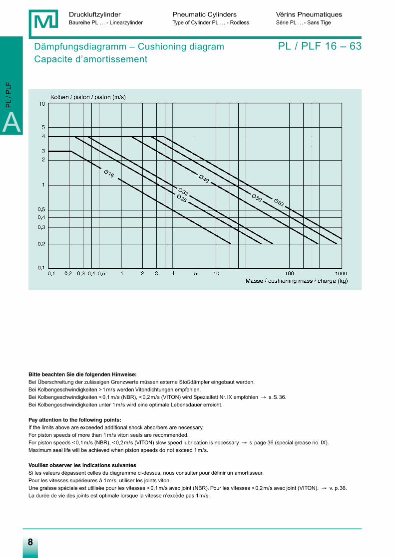
Bitte beachten Sie die folgenden Hinweise:Bei Überschreitung der zulässigen Grenzwerte müssen externe Stoßdämpfer eingebaut werden.Bei Kolbengeschwindigkeiten >1m/s werden Vitondichtungen empfohlen.Bei Kolbengeschwindigkeiten <0,1m/s (NBR), <0,2m/s (VITON) wird Spezialfett Nr. IX empfohlen → s.S.36.Bei Kolbengeschwindigkeiten unter 1m/s wird eine optimale Lebensdauer erreicht.
Pay attention to the following points:If the limits above are exceeded additional shock absorbers are necessary.For piston speeds of more than 1m/s viton seals are recommended.For piston speeds <0,1m/s (NBR), <0,2m/s (VITON) slow speed lubrication is necessary → s.page 36 (special grease no. IX).Maximum seal life will be achieved when piston speeds do not exceed 1m/s.
Vouillez observer les indications suivantesSi les valeurs dépassent celles du diagramme ci-dessus, nous consulter pour définir un amortisseur.Pour les vitesses supérieures à 1m/s, utiliser les joints viton.Une graisse spéciale est utilisée pour les vitesses <0,1m/s avec joint (NBR). Pour les vitesses <0,2m/s avec joint (VITON). → v. p.36.La durée de vie des joints est optimale lorsque la vitesse n’excède pas 1m/s.
Dämpfungsdiagramm – Cushioning diagram PL / PLF 16 – 63Capacite d’amortissement
A
PL
/ PLF
Medan-Katalog_neu_2-2009.qxd 26.02.2009 16:42 Uhr Seite 8
9
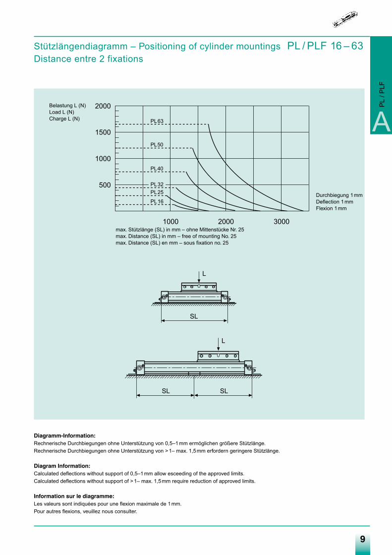
Stützlängendiagramm – Positioning of cylinder mountings PL / PLF 16 – 63Distance entre 2 fixations
Diagramm-Information:Rechnerische Durchbiegungen ohne Unterstützung von 0,5–1mm ermöglichen größere Stützlänge.Rechnerische Durchbiegungen ohne Unterstützung von >1– max. 1,5mm erfordern geringere Stützlänge.
Diagram Information:Calculated deflections without support of 0,5–1mm allow esceeding of the approved limits.Calculated deflections without support of >1– max. 1,5mm require reduction of approved limits.
Information sur le diagramme:Les valeurs sont indiquées pour une flexion maximale de 1mm.Pour autres flexions, veuillez nous consulter.
500
1000
1500
2000
1000 2000 3000
PL16
PL25PL32
PL40
PL50
PL63
L
SL
L
SL SL
max. Stützlänge (SL) in mm – ohne Mittenstücke Nr. 25max. Distance (SL) in mm – free of mounting No. 25max. Distance (SL) en mm – sous fixation no. 25
Durchbiegung 1mmDeflection 1mmFlexion 1mm
Belastung L (N)Load L (N)Charge L (N) A
PL
/ PLF
Medan-Katalog_neu_2-2009.qxd 26.02.2009 16:42 Uhr Seite 9
10
Druckluftzylinder Pneumatic Cylinders Vérins PneumatiquesBaureihe PL … - Linearzylinder Type of Cylinder PL … - Rodless Série PL …- Sans Tige
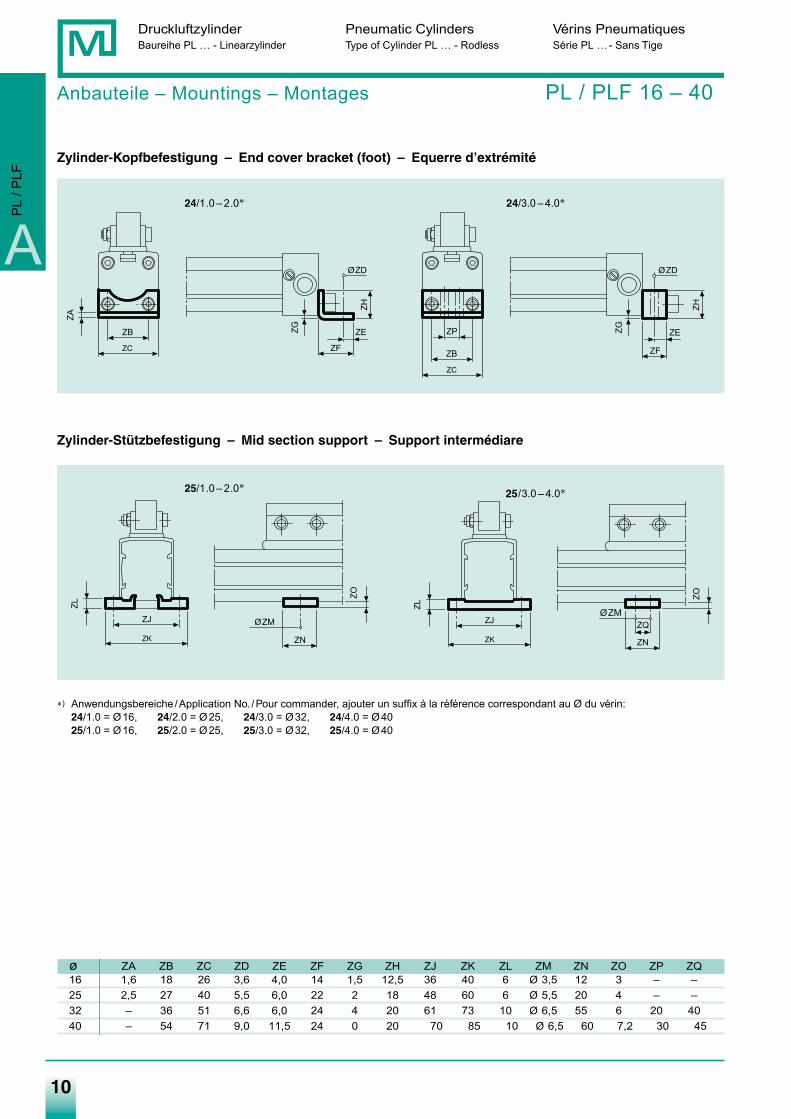
Anbauteile – Mountings – Montages PL / PLF 16 – 40
Zylinder-Kopfbefestigung – End cover bracket (foot) – Equerre d’extrémité
Zylinder-Stützbefestigung – Mid section support – Support intermédiare
∗) Anwendungsbereiche /Application No. /Pour commander, ajouter un suffix à la référence correspondant au Ø du vérin:24/1.0 = Ø16, 24/2.0 = Ø25, 24/3.0 = Ø32, 24/4.0 = Ø4025/1.0 = Ø16, 25/2.0 = Ø25, 25/3.0 = Ø32, 25/4.0 = Ø40
ø ZA ZB ZC ZD ZE ZF ZG ZH ZJ ZK ZL ZM ZN ZO ZP ZQ16 1,6 18 26 3,6 4,0 14 1,5 12,5 36 40 6 Ø 3,5 12 3 – –25 2,5 27 40 5,5 6,0 22 2 18 48 60 6 Ø 5,5 20 4 – –32 – 36 51 6,6 6,0 24 4 20 61 73 10 Ø 6,5 55 6 20 4040 – 54 71 9,0 11,5 24 0 20 70 85 10 Ø 6,5 60 7,2 30 45
ZC
ZB
ZA
ZH
ØZD
ZF
ZEZG
ZC
ZB
ZP
ZH
ØZD
ZF
ZEZGØZM
ZN
ZO
ZK
ZJ
ZL
ZK
ZJ
ZL
ØZM
ZN
ZO
ZQ
24/1.0 – 2.0∗ 24/3.0 – 4.0∗
25/3.0 – 4.0∗25/1.0 – 2.0∗
A
PL
/ PLF
Medan-Katalog_neu_2-2009.qxd 26.02.2009 16:42 Uhr Seite 10
11
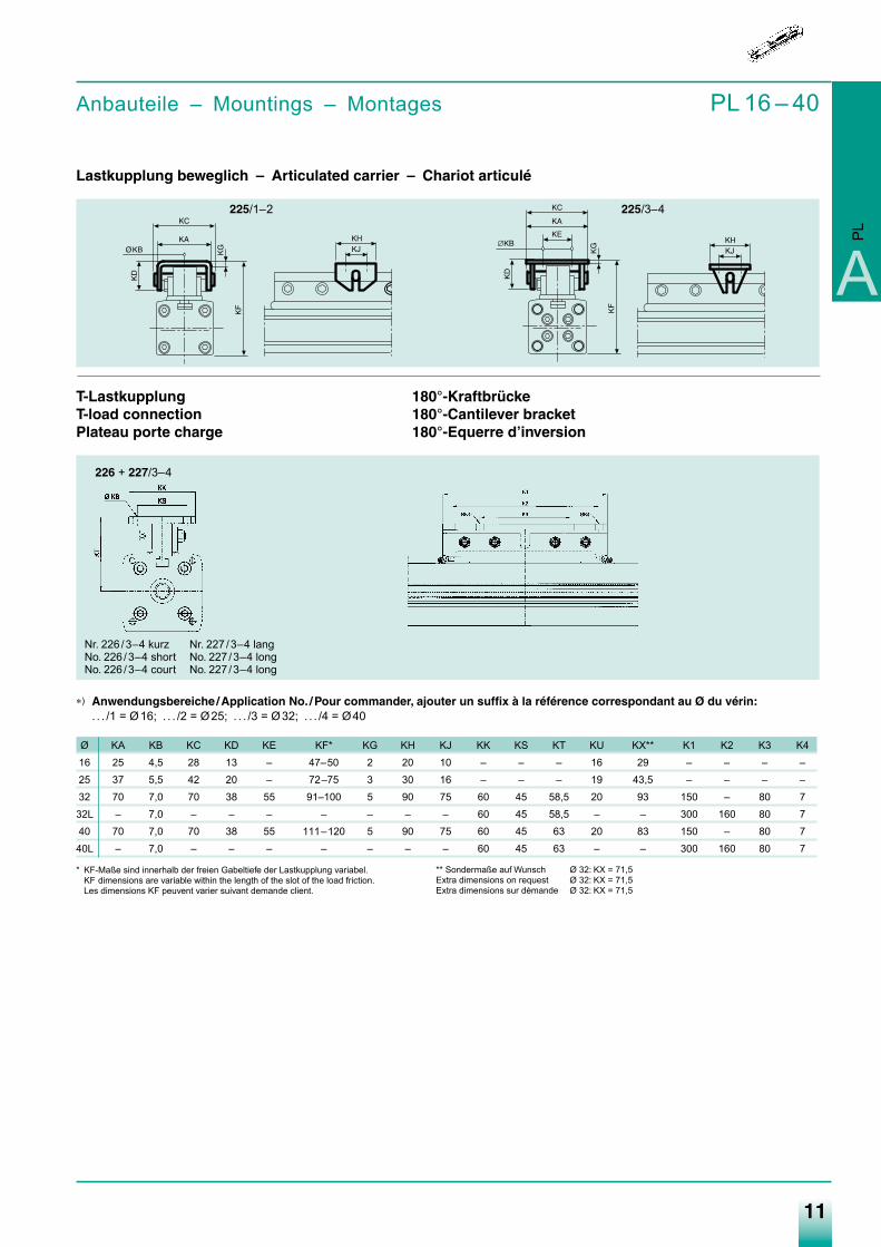
Anbauteile – Mountings – Montages PL 16 – 40
Lastkupplung beweglich – Articulated carrier – Chariot articulé
T-Lastkupplung 180°-KraftbrückeT-load connection 180°-Cantilever bracketPlateau porte charge 180°-Equerre d’inversion
∗) Anwendungsbereiche /Application No. /Pour commander, ajouter un suffix à la référence correspondant au Ø du vérin:. . . /1 = Ø16; . . . /2 = Ø25; . . . /3 = Ø32; . . . /4 = Ø40
Ø KA KB KC KD KE KF* KG KH KJ KK KS KT KU KX** K1 K2 K3 K416 25 4,5 28 13 – 47–50 2 20 10 – – – 16 29 – – – –25 37 5,5 42 20 – 72–75 3 30 16 – – – 19 43,5 – – – –32 70 7,0 70 38 55 91–100 5 90 75 60 45 58,5 20 93 150 – 80 732L – 7,0 – – – – – – – 60 45 58,5 – – 300 160 80 740 70 7,0 70 38 55 111–120 5 90 75 60 45 63 20 83 150 – 80 740L – 7,0 – – – – – – – 60 45 63 – – 300 160 80 7
* KF-Maße sind innerhalb der freien Gabeltiefe der Lastkupplung variabel.KF dimensions are variable within the length of the slot of the load friction.Les dimensions KF peuvent varier suivant demande client.
225/1–2
226 + 227/3–4
225/3–4
A
PL
Nr. 226 /3–4 kurz Nr. 227 /3–4 langNo. 226 /3–4 short No. 227 /3–4 longNo. 226 /3–4 court No. 227 /3–4 long
** Sondermaße auf Wunsch Ø 32: KX = 71,5Extra dimensions on request Ø 32: KX = 71,5Extra dimensions sur démande Ø 32: KX = 71,5
Medan-Katalog_neu_2-2009.qxd 26.02.2009 16:43 Uhr Seite 11
12
Druckluftzylinder Pneumatic Cylinders Vérins PneumatiquesBaureihe PL … - Linearzylinder Type of Cylinder PL … - Rodless Série PL …- Sans Tige
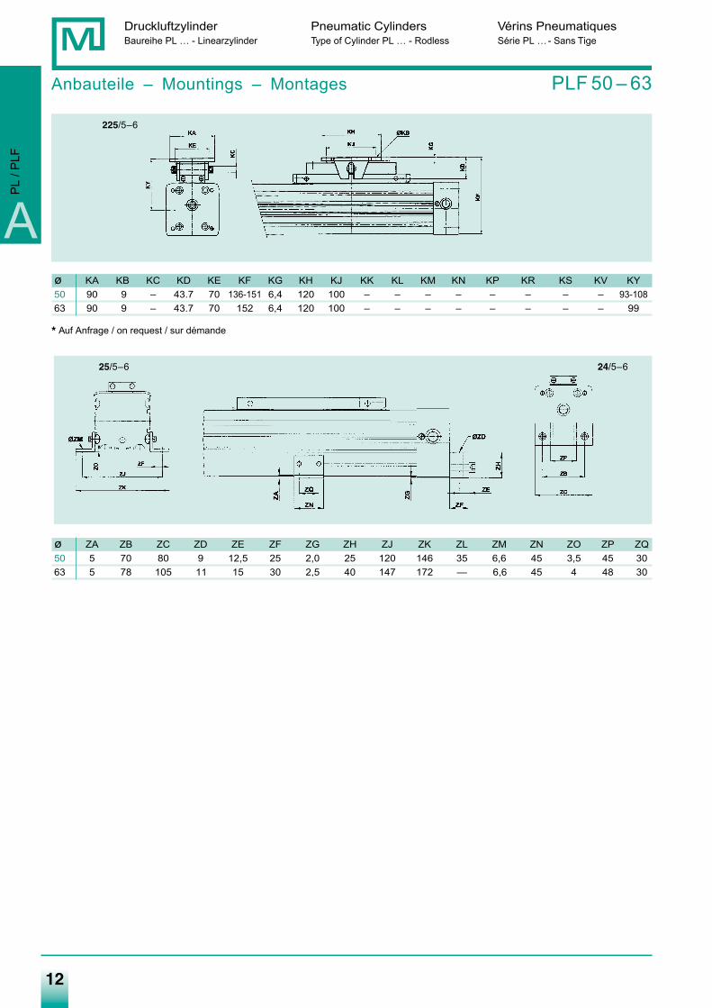
Anbauteile – Mountings – Montages PLF 50 – 63
225/5–6
25/5–6 24/5–6
ø KA KB KC KD KE KF KG KH KJ KK KL KM KN KP KR KS KV KY50 90 9 – 43.7 70 136-151 6,4 120 100 – – – – – – – – 93-10863 90 9 – 43.7 70 152 6,4 120 100 – – – – – – – – 99
* Auf Anfrage / on request / sur démande
ø ZA ZB ZC ZD ZE ZF ZG ZH ZJ ZK ZL ZM ZN ZO ZP ZQ50 5 70 80 9 12,5 25 2,0 25 120 146 35 6,6 45 3,5 45 3063 5 78 105 11 15 30 2,5 40 147 172 — 6,6 45 4 48 30
A
PL
/ PLF
Medan-Katalog_neu_2-2009.qxd 26.02.2009 16:43 Uhr Seite 12
13
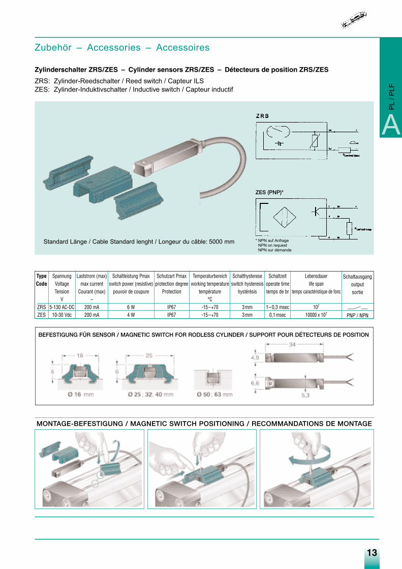
Zubehör – Accessories – Accessoires
Zylinderschalter ZRS/ZES – Cylinder sensors ZRS/ZES – Détecteurs de position ZRS/ZES
ZRS: Zylinder-Reedschalter / Reed switch / Capteur ILSZES: Zylinder-Induktivschalter / Inductive switch / Capteur inductif
A
PL
/ PLF
* NPN auf AnfrageNPN on requestNPN sur démande
Standard Länge / Cable Standard lenght / Longeur du câble: 5000 mm
ZES (PNP)*
TypeCode
ZRSZES
SpannungVoltageTension
V5-130 AC-DC
10-30 Vdc
Laststrom (max)max current
Courant (max)–
200 mA200 mA
Schaltleistung Pmaxswitch power (resistive)
pouvoir de coupure
6 W4 W
Schutzart Pmaxprotection degree
Protection
IP67IP67
Temperaturbereichworking temperature
température°C
-15–+70-15–+70
Schalthystereseswitch hysteresis
hystérésis
3mm3mm
Schaltzeitoperate timetemps de br
1–0,3 msec0,1msec
Lebensdauerlife span
temps caractéristique de fonc
107
10000 x 107
Schaltausgangoutputsortie
PNP / NPN
BEFESTIGUNG FÜR SENSOR / MAGNETIC SWITCH FOR RODLESS CYLINDER / SUPPORT POUR DÉTECTEURS DE POSITION
MONTAGE-BEFESTIGUNG / MAGNETIC SWITCH POSITIONING / RECOMMANDATIONS DE MONTAGE
Medan-Katalog_neu_2-2009.qxd 26.02.2009 16:43 Uhr Seite 13
14
Druckluftzylinder Pneumatic Cylinders Vérins PneumatiquesBaureihe PL … - Linearzylinder Type of Cylinder PL … - Rodless Série PL …- Sans Tige
A
PL
/ PLF
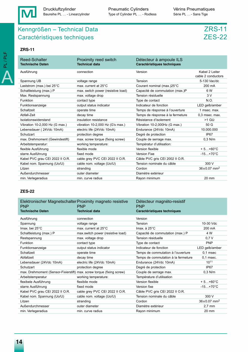
ZRS-11
Reed-Schalter Proximity reed switch Détecteur à ampoule ILSTechnische Daten Technical data Caractéristiques techniques
Ausführung connection Version Kabel 2 Leitercable 2 conductors
Spannung UB voltage range Tension 5-130 Vac/dcLaststrom (max.) bei 25°C max. current at 25°C Courant nominal (max.)25°C 200 mASchaltleistung (max.) P max. switch power (resistive load) Capacité de commutation (max.)P 6 WMax. Restspannung max. voltage drop Tension résiduelle 3 VFunktion contact type Type de contact N.O.Funktionsanzeige output status indicator Indicateur de fonction LED gelb/amberSchaltzeit operate time Temps de résponse à l’ouverture 1 msec. max.Abfall-Zeit decay time Temps de résponse à la fermeture 0,3 msec. max.Isolationswiderstand insulation resistance Résistance d’isolement >1 GΩ
Vibration 10-2,000 Hz (G max.) vibration 10-2,000 Hz (G’s max.) Vibration 10-2,000Hz (G max.) 50 GLebensdauer ( 24Vdc 10mA) electric life (24Vdc 10mA) Endurance (24Vdc 10mA) 10.000.000Schutzart protection degree Degré de protection IP67max. Drehmoment (Gewindestift) max. screw torque (fixing screw) Couple de serrage max. 0,3 N/mArbeitstemperatur: working temperature: Températur d’utilisation:flexible Ausführung flexible mode Version flexible + 5…+60°Cstarre Ausführung fixed mode Version Fixe -15…+70°CKabel PVC grau CEI 2022 II O.R. cable grey PVC CEI 2022 II O.R. Câble PVC gris CEI 2002 II O.R.Kabel nom. Spannung (Uo/U) cable nom. voltage (Uo/U) Tension nominale du câble 300 V Litzen stranding Cordon 36x0.07 mm2
Außendurchmesser outer diameter Diamètre extérieurmin. Verlegeradius min. curve radius Rayon minimum 20 mm
ZES-22
Elektronischer MagnetschalterProximity magneto resistive Détecteur magnéto-resistifPNP PNP PNPTechnische Daten Technical data Caractéristiques techniques
Ausführung connection VersionSpannung voltage range Tension 10-30 VdcImax. bei 25°C max. current at 25°C Imax. à 25°C 200 mASchaltleistung (max.) P max.switch power (resistive load) Capacité de commutation (max.) P 4 WRestspannung max. voltage drop Tension résiduelle 0,7 VFunktion contact type Type de contact PNPFunktionsanzeige output status indicator Indicateur de fonction LED gelb/amberSchaltzeit operate time Temps de commutation à l’ouverture 0,1 msecAbfallzeit decay time Temps de commutation à la fermeture 0,1 msec.Lebensdauer (24Vdc 10mA) electric life (24Vdc 10mA) Endurance (24Vdc 10mA) 1011
Schutzart protection degree Degré de protection IP67max. Drehmoment (Sensor-Fixierstift) max. screw torque (fixing screw) Couple de serrage max. 0,3 N/mArbeitstemperatur working temperature: Température d’utilisationflexibele Ausführung flexibile mode Version flexible + 5…+60°Cstarre Ausführung fixed mode Version fixe -15…+70°CKabel PVC grau CEI 2022 II O.R. cable grey PVC CEI 2022 II O.R. Câble PVC gris CEI 2022 II O.R.Kabel nom. Spannung (Uo/U) cable nom. voltage (Uo/U) Tension nominale du câble 300 VLitzen stranding Cordon 36x0.07 mm2
Außendurchmesser outer diameter Diamètre extérieur 2,7 mmmin. Verlegeradius min. curve radius Rayon minimum 20 mm
Kenngrößen – Technical Data ZRS-11Caractéristiques techniques ZES-22
Medan-Katalog_neu_2-2009.qxd 26.02.2009 16:43 Uhr Seite 14
15
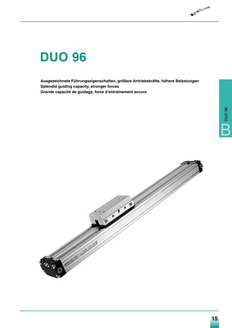
DUO 96
Ausgezeichnete Führungseigenschaften, größere Antriebskräfte, höhere BelastungenSplendid guiding capacity, stronger forcesGrande capacité de guidage, force d’entraînement accure
B
DU
O 9
6
Medan-Katalog_neu_2-2009.qxd 26.02.2009 16:43 Uhr Seite 15
16
Druckluftzylinder Pneumatic Cylinders Vérins PneumatiquesDUO 96 DUO 96 DUO 96
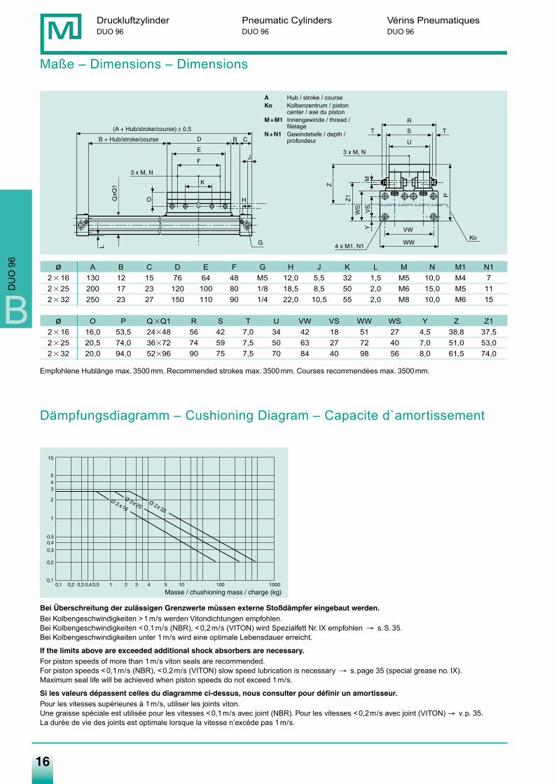
Maße – Dimensions – Dimensions
ø A B C D E F G H J K L M N M1 N12�16 130 12 15 76 64 48 M5 12,0 5,5 32 1,5 M5 10,0 M4 72�25 200 17 23 120 100 80 1/8 18,5 8,5 50 2,0 M6 15,0 M5 112�32 250 23 27 150 110 90 1/4 22,0 10,5 55 2,0 M8 10,0 M6 15
ø O P Q�Q1 R S T U VW VS WW WS Y Z Z12�16 16,0 53,5 24�48 56 42 7,0 34 42 18 51 27 4,5 38,8 37,52�25 20,5 74,0 36�72 74 59 7,5 50 63 27 72 40 7,0 51,0 53,02�32 20,0 94,0 52�96 90 75 7,5 70 84 40 98 56 8,0 61,5 74,0
Bei Überschreitung der zulässigen Grenzwerte müssen externe Stoßdämpfer eingebaut werden.Bei Kolbengeschwindigkeiten >1m/s werden Vitondichtungen empfohlen.Bei Kolbengeschwindigkeiten <0,1m/s (NBR), <0,2m/s (VITON) wird Spezialfett Nr. IX empfohlen → s.S.35.Bei Kolbengeschwindigkeiten unter 1m/s wird eine optimale Lebensdauer erreicht.
If the limits above are exceeded additional shock absorbers are necessary.For piston speeds of more than 1m/s viton seals are recommended.For piston speeds <0,1m/s (NBR), <0,2m/s (VITON) slow speed lubrication is necessary → s.page 35 (special grease no. IX).Maximum seal life will be achieved when piston speeds do not exceed 1m/s.
Si les valeurs dépassent celles du diagramme ci-dessus, nous consulter pour définir un amortisseur.Pour les vitesses supérieures à 1m/s, utiliser les joints viton.Une graisse spéciale est utilisée pour les vitesses <0,1m/s avec joint (NBR). Pour les vitesses <0,2m/s avec joint (VITON) → v.p. 35.La durée de vie des joints est optimale lorsque la vitesse n’excède pas 1m/s.
Empfohlene Hublänge max. 3500mm. Recommended strokes max. 3500mm. Courses recommendées max. 3500mm.
L
A Hub / stroke / courseKo Kolbenzentrum / piston
center / axe du pistonM+M1 Innengewinde / thread /
filetageN+N1 Gewindetiefe / depth /
profondeur
Dämpfungsdiagramm – Cushioning Diagram – Capacite d`amortissement
B
DU
O 9
6
Medan-Katalog_neu_2-2009.qxd 26.02.2009 16:43 Uhr Seite 16
17
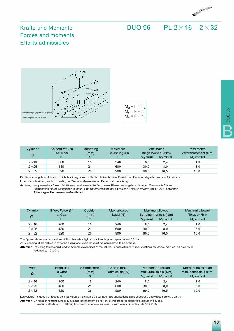
Kräfte und Momente DUO 96 PL 2 � 16 – 2 � 32Forces and momentsEfforts admissibles
Ma = F � haMr = F � hrMv = F � hv
Zylinder Kolbenkraft (N) Dämpfung Maximale Maximales Maximales
Ø bei 6bar (mm) Belastung (N) Biegemoment (Nm) Verdrehmoment (Nm)F S L Ma axial Mr radial Mv zentral
2 �16 200 15 240 8,0 2,4 1,02 � 25 480 21 600 30,0 8,0 6,02 � 32 820 26 900 60,0 16,5 10,0
Die Tabellenangaben stellen die höchstzulässigen Werte für 6bar bei stoßfreiem Betrieb und Geschwindigkeiten von v � 0,2m/s dar.Eine Überschreitung, auch kurzfristig, der Werte im dynamisierten Bereich ist unzulässig.Achtung: Im grenznahen Einsatzfall können resultierende Kräfte zu einer Überschreitung der zulässigen Grenzwerte führen.
Bei undefinierbaren Situationen ist daher eine Unterschreitung der zulässigen Belastungswerte um 10–20% notwendig.Bitte fragen Sie unseren Außendienst.
Cylinder Effect Force (N) Cushion Max. allowed Maximal allowed Maximal allowed
Ø at 6bar (mm) Load (N) Bending moment (Nm) Torque (Nm)F S L Ma axial Mr radial Mv central
2 � 16 200 15 240 8,0 2,4 1,02 � 25 480 21 600 30,0 8,0 6,02 � 32 820 26 900 60,0 16,5 10,0
The figures above are max. values at 6bar based on light shock free duty and speed of v � 0,2m/s.An exceeding of the values in dynamic operations, even for short moments, have to be avoided.Attention: Resulting forces could lead to extreme exceedings of the values. In case of undefinable situations the above max. values have to be
reduced by 10–20%.
Vérin Effort (N) Amortissment Charge max. Moment de flexion Moment de rotation
Ø à 6bar (mm) admissible (N) max. admissible (Nm) max. admissible (Nm)F S L Ma axial Mr radial Mv central
2 � 16 200 15 240 8,0 2,4 1,02 � 25 480 21 600 30,0 8,0 6,02 � 32 820 26 900 60,0 16,5 10,0
Les valeurs indiquées ci-dessus sont les valeurs maximales á 6bar pour des applications sans chocs et à une vitesse de v � 0,2m/s.Attention: En fonctionnement dynamique, éviter tout moment de flexion latéral ou de dépasser les valeurs indiquées.
Si certains efforts sont indéfinis, il convient de réduire les valeurs maximums du tableau de 10 à 20%.
Führungsachse/guidiging axles/axe de guidage
Kolbenachse/piston axel/axe du piston
B
DU
O 9
6
F
Medan-Katalog_neu_2-2009.qxd 26.02.2009 16:43 Uhr Seite 17
18
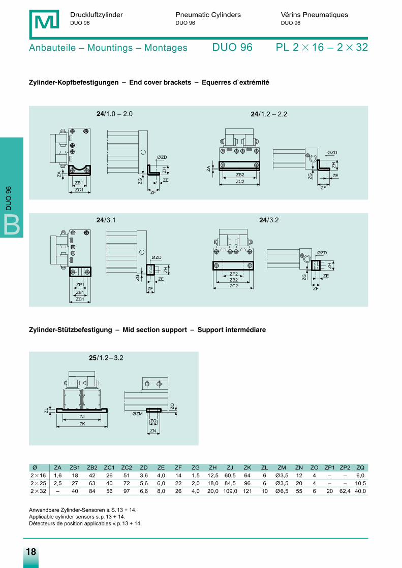
Anbauteile – Mountings – Montages DUO 96 PL 2 � 16 – 2 � 32
Zylinder-Kopfbefestigungen – End cover brackets – Equerres d`extrémité
24/1.2 – 2.2
24/3.1 24/3.2
Zylinder-Stützbefestigung – Mid section support – Support intermédiare
25/1.2–3.2
Ø ZA ZB1 ZB2 ZC1 ZC2 ZD ZE ZF ZG ZH ZJ ZK ZL ZM ZN ZO ZP1 ZP2 ZQ2�16 1,6 18 42 26 51 3,6 4,0 14 1,5 12,5 60,5 64 6 Ø3,5 12 4 – – 6,02�25 2,5 27 63 40 72 5,6 6,0 22 2,0 18,0 84,5 96 6 Ø3,5 20 4 – – 10,52�32 – 40 84 56 97 6,6 8,0 26 4,0 20,0 109,0 121 10 Ø6,5 55 6 20 62,4 40,0
Anwendbare Zylinder-Sensoren s.S.13 + 14.Applicable cylinder sensors s.p.13 + 14.Détecteurs de position applicables v.p.13 + 14.
ZF
ZHØZD
ZEZG
ZA
ZC1ZB1
ZH
ØZD
ZF
ZEZG
ZC2ZB2
ZA
ZH
ØZD
ZF
ZEZG
ZC1ZB1
ZP1
ØZM
ZN
ZO
ZQZKZJ
ZL
ZH
ØZD
ZF
ZE
ZG
ZC2ZB2ZP2
Druckluftzylinder Pneumatic Cylinders Vérins PneumatiquesDUO 96 DUO 96 DUO 96
24/1.0 – 2.0
B
DU
O 9
6
Medan-Katalog_neu_2-2009.qxd 26.02.2009 16:43 Uhr Seite 18
19
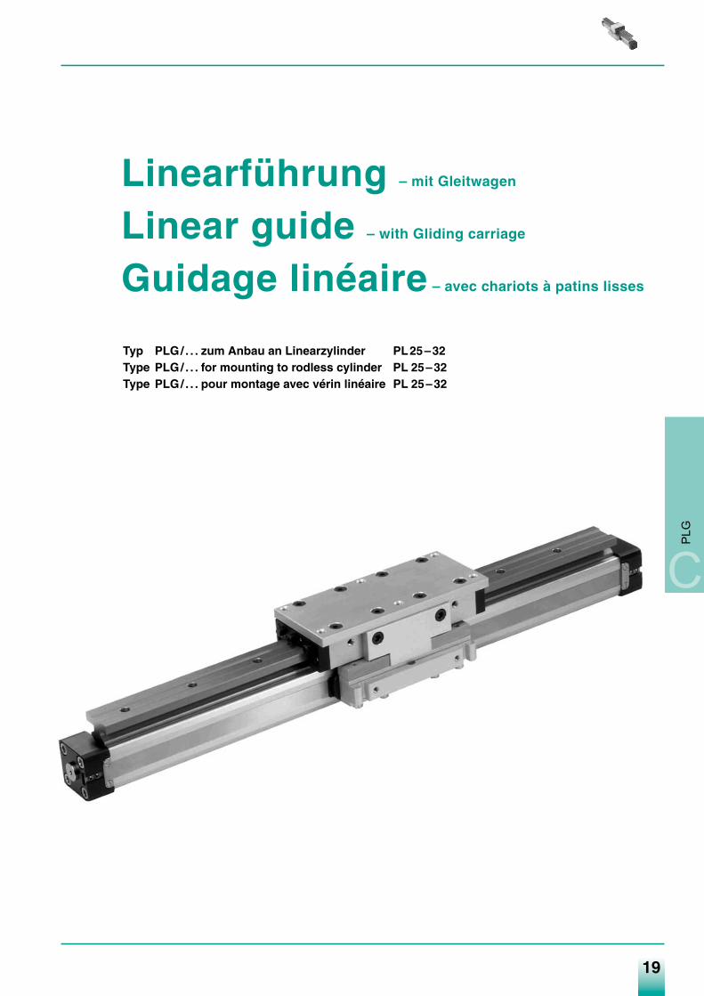
Linearführung – mit Gleitwagen
Linear guide – with Gliding carriage
Guidage linéaire – avec chariots à patins lisses
Typ PLG/ . . . zum Anbau an Linearzylinder PL25–32Type PLG/ . . . for mounting to rodless cylinder PL 25–32Type PLG/ . . . pour montage avec vérin linéaire PL 25–32
C
PLG
Medan-Katalog_neu_2-2009.qxd 26.02.2009 16:43 Uhr Seite 19
20
Linearführung Linear guide Guidage linéaire
Technische Beschreibung – Gleitführungssystem
Dieses besonders robuste Linearführungssystem in den Baureihen PLG 25 und PLG 32 wurde speziell für Anwendungen in der Automatisierung und Handhabungstechnik entwickelt. Als Antriebselement kommt unser bewährter kolbenstangenloser Zylinder in den ø-Reihen 16–32mm zum Einsatz.Für die Zylinder-ø-Reihen 25mm + 32mm stehen bezüglich der Belastbarkeit jeweils 2 Ausführungen zur Verfügung, deren Einsatzbereicheaus den technischen Datenblättern zu entnehmen sind.Es können also je nach Bedarf folgende Baureihen zum Einsatz gelangen:2.2 PLG 25/2 – 2-Gleitwagen-System für Zylinder ø253.2 PLG 32/2 – 2-Gleitwagen-System für Zylinder ø32Neben der bekannten Technik des Arbeitszylinders (siehe Katalog „Linearzylinder“) hier die wesentlichen Modulmerkmale:Besondere Eigenschaften• Hohe Verschleißfestigkeit • Geräuscharm • Unempfindlich gegen Schmutz und Feuchtigkeit• Spiel einstellbar • Auswechselbare Gleitelemente • Korrosionsbeständig• Hohe statische Belastbarkeit • Unempfindlich gegen Stöße • Geringes Gewicht
für alle Richtungen und SchwingungenDer Führungsmodul ist jederzeit nachrüstbar.
Technical description – Gliding system
This particular robust linear guiding system for the types PLG 25 and PLG 32 was specially constructed for heavy applications and automation systems. The standard well proven rodless cylinder PL . . is used as the motive force in the bore sizes from ø16–32.Two guide systems are available for ø25mm + 32mm. Dimensions and technical datas are as below:2.2 PLG 25/2 – 2 Gliding carriages-system for cylinder ø 25mm3.2 PLG 32/2 – 2 Gliding carriages-system for cylinder ø 32mmThe important characteristics of the guided cylinders are:
• high resistance to wear • quiet running • high resistance to dirt & moisture• tolerances adjustable • ability to take high loads & moments • low weight
in all directions• high resistance to corrosion • ability to take shock loadings and • interchangeable gliding elements
vibrations against blows and vibrationsIt is possible to retrofit a guide to an existing cylinder.
Description technique – System chariots à patins lisses
Le système de guidage linéaire des séries PLG 25 et PLG 32 se distingue par sa robustesse et a été conçu spécialement pour des applications en automation et manutention. Les vérins linéaires des ø 16–32mm sont utilisés comme élement d’entrainement.Concernant la capacité de charge des séries ø 25 et 32 deux exécutions sont à disposition, dont les caractéristiques de charge sontmentionnées dans les feuilles respectives du catalogue.Selon besoin les séries suivantes sont à disposition:2.2 PLG 25/2 – Système avec deux chariots à patins lisses avec vérin ø 25mm3.2 PLG 32/2 – Système avec deux chariots à patins lisses avec vérin ø 32mmLes caractéristiques des vérins sont mentionnés dans les pages respectives du catalogue.Les modules se distinguent par leur
• robustesse • silencieux • résistance aux impurtés et à l’humidité• jeu des glissières règlable • glissières interchangeables • resistance à la corrosion• grande capacité de charge • insensible aux chocs et aux efforts• faible poids efforts alternésLes modules de guidage existent également en lot de rattrapage.
C
PLG
Medan-Katalog_neu_2-2009.qxd 26.02.2009 16:43 Uhr Seite 20
21
C
PLG
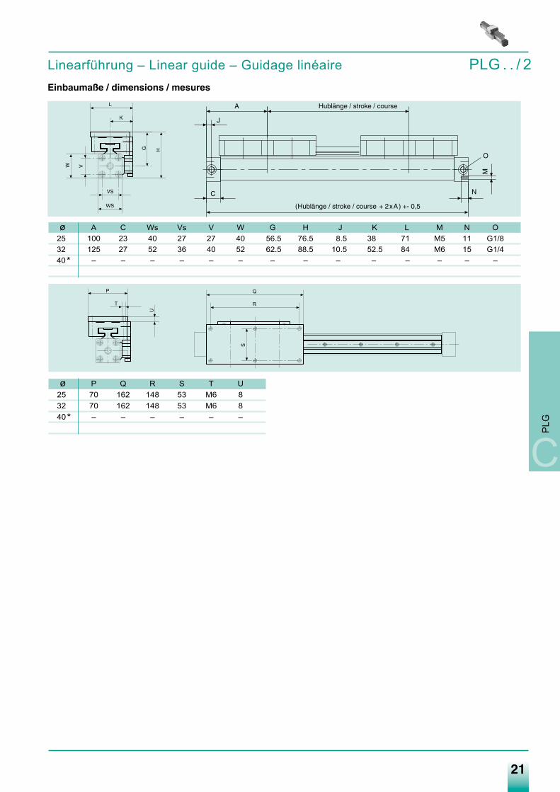
Linearführung – Linear guide – Guidage linéaire PLG . . / 2Einbaumaße / dimensions / mesures
T
U
P Q
R
S
ø A C Ws Vs V W G H J K L M N O25 100 23 40 27 27 40 56.5 76.5 8.5 38 71 M5 11 G1/832 125 27 52 36 40 52 62.5 88.5 10.5 52.5 84 M6 15 G1/440* – – – – – – – – – – – – – –
ø P Q R S T U25 70 162 148 53 M6 832 70 162 148 53 M6 840* – – – – – –
Medan-Katalog_neu_2-2009.qxd 26.02.2009 16:43 Uhr Seite 21
Linearführung – Linear guide – Guidage linéaire PLG . . / 2
22
Linearführung Linear guide Guidage linéaire
C
PLG
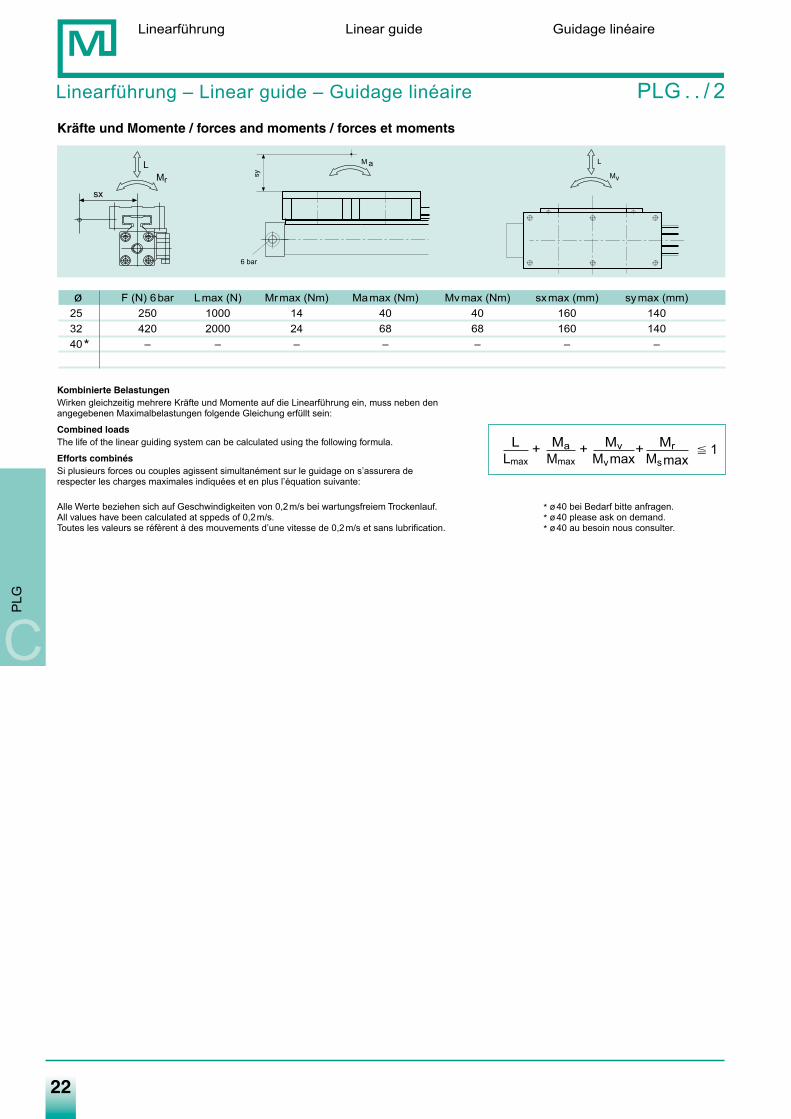
Kräfte und Momente / forces and moments / forces et moments
Kombinierte BelastungenWirken gleichzeitig mehrere Kräfte und Momente auf die Linearführung ein, muss neben den angegebenen Maximalbelastungen folgende Gleichung erfüllt sein:
Combined loadsThe life of the linear guiding system can be calculated using the following formula.
Efforts combinésSi plusieurs forces ou couples agissent simultanément sur le guidage on s’assurera de respecter les charges maximales indiquées et en plus l’équation suivante:
Alle Werte beziehen sich auf Geschwindigkeiten von 0,2m/s bei wartungsfreiem Trockenlauf. * ø40 bei Bedarf bitte anfragen.All values have been calculated at sppeds of 0,2m/s. * ø40 please ask on demand.Toutes les valeurs se réfèrent à des mouvements d’une vitesse de 0,2m/s et sans lubrification. * ø40 au besoin nous consulter.
Mr
L
sx
M
6 barsy
L
Mv
ø F (N) 6bar Lmax (N) Mrmax (Nm) Mamax (Nm) Mvmax (Nm) sxmax (mm) symax (mm)25 250 1000 14 40 40 160 14032 420 2000 24 68 68 160 14040* – – – – – – –
L Ma Mv MrLmax Mmax Mvmax Msmax
� 1+ + +
a
Medan-Katalog_neu_2-2009.qxd 26.02.2009 16:43 Uhr Seite 22
23
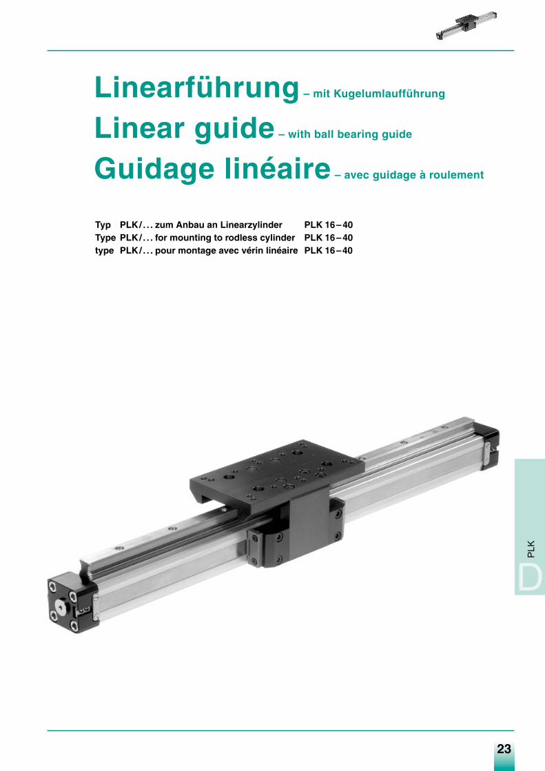
Linearführung – mit Kugelumlaufführung
Linear guide – with ball bearing guide
Guidage linéaire – avec guidage à roulement
Typ PLK/ . . . zum Anbau an Linearzylinder PLK 16– 40Type PLK/ . . . for mounting to rodless cylinder PLK 16– 40type PLK/ . . . pour montage avec vérin linéaire PLK 16–40
PLK
D
Medan-Katalog_neu_2-2009.qxd 26.02.2009 16:43 Uhr Seite 23
24
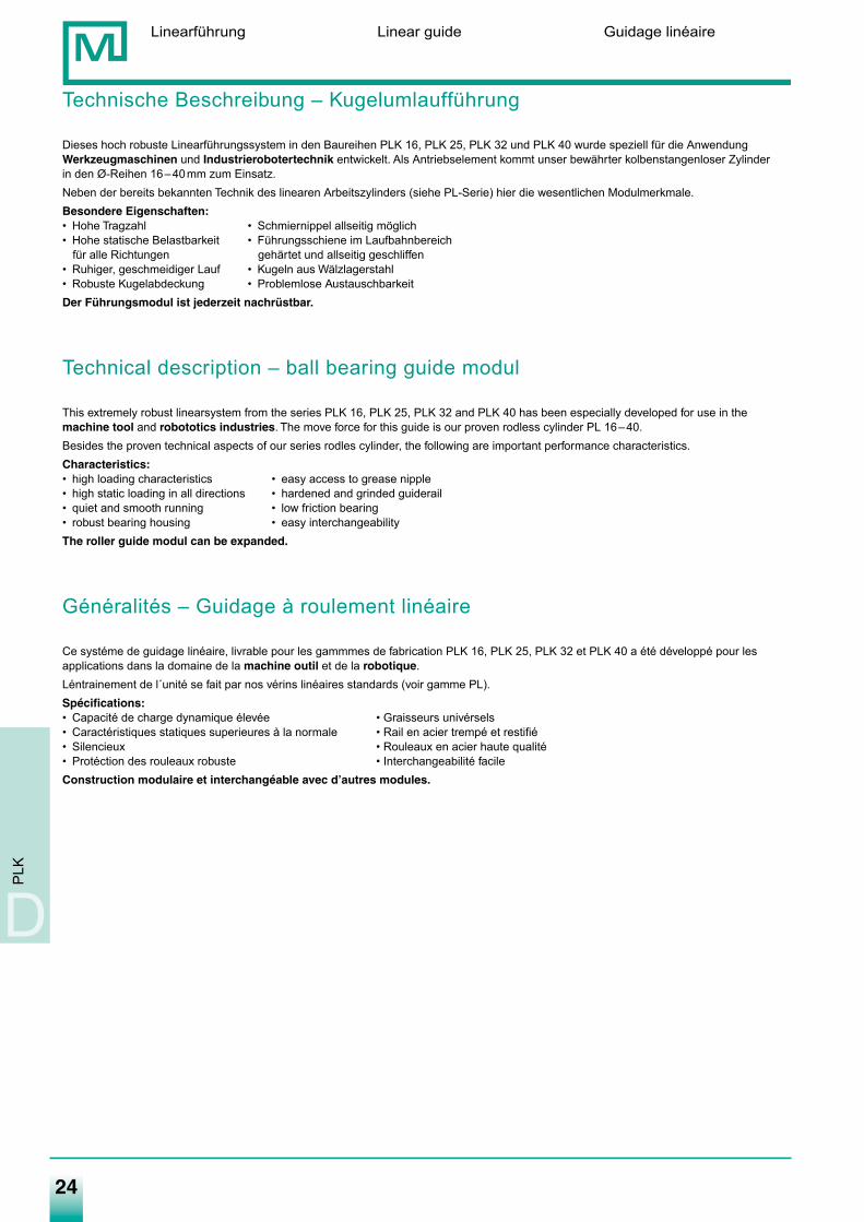
Technische Beschreibung – Kugelumlaufführung
Dieses hoch robuste Linearführungssystem in den Baureihen PLK 16, PLK 25, PLK 32 und PLK 40 wurde speziell für die AnwendungWerkzeugmaschinen und Industrierobotertechnik entwickelt. Als Antriebselement kommt unser bewährter kolbenstangenloser Zylinder in den Ø-Reihen 16–40mm zum Einsatz.Neben der bereits bekannten Technik des linearen Arbeitszylinders (siehe PL-Serie) hier die wesentlichen Modulmerkmale.Besondere Eigenschaften:• Hohe Tragzahl • Schmiernippel allseitig möglich• Hohe statische Belastbarkeit • Führungsschiene im Laufbahnbereich
für alle Richtungen gehärtet und allseitig geschliffen• Ruhiger, geschmeidiger Lauf • Kugeln aus Wälzlagerstahl• Robuste Kugelabdeckung • Problemlose AustauschbarkeitDer Führungsmodul ist jederzeit nachrüstbar.
Technical description – ball bearing guide modul
This extremely robust linearsystem from the series PLK 16, PLK 25, PLK 32 and PLK 40 has been especially developed for use in themachine tool and robototics industries. The move force for this guide is our proven rodless cylinder PL 16–40.Besides the proven technical aspects of our series rodles cylinder, the following are important performance characteristics.Characteristics:• high loading characteristics • easy access to grease nipple• high static loading in all directions • hardened and grinded guiderail• quiet and smooth running • low friction bearing• robust bearing housing • easy interchangeabilityThe roller guide modul can be expanded.
Généralités – Guidage à roulement linéaire
Ce systéme de guidage linéaire, livrable pour les gammmes de fabrication PLK 16, PLK 25, PLK 32 et PLK 40 a été développé pour lesapplications dans la domaine de la machine outil et de la robotique.Léntrainement de l´unité se fait par nos vérins linéaires standards (voir gamme PL).Spécifications:• Capacité de charge dynamique élevée • Graisseurs univérsels• Caractéristiques statiques superieures à la normale • Rail en acier trempé et restifié• Silencieux • Rouleaux en acier haute qualité• Protéction des rouleaux robuste • Interchangeabilité facileConstruction modulaire et interchangéable avec d’autres modules.
Linearführung Linear guide Guidage linéaire
D
PLK
Medan-Katalog_neu_2-2009.qxd 26.02.2009 16:43 Uhr Seite 24
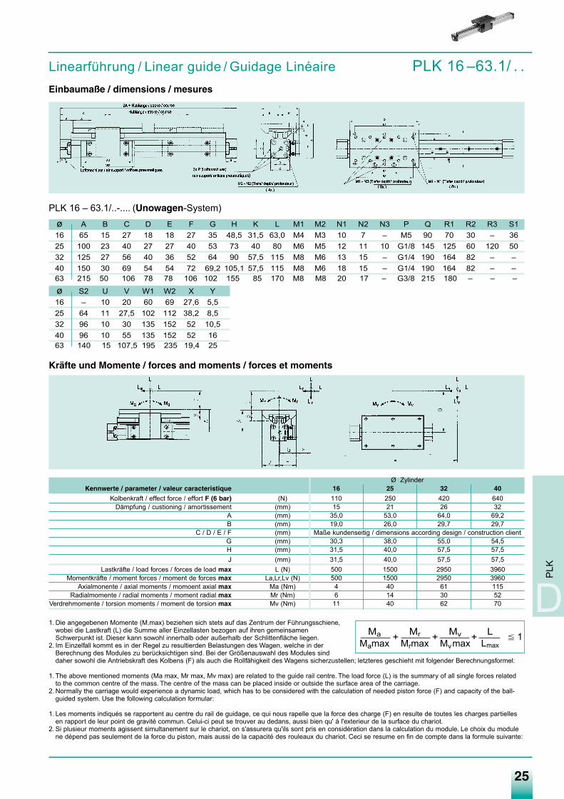
1. Die angegebenen Momente (M.max) beziehen sich stets auf das Zentrum der Führungsschiene,wobei die Lastkraft (L) die Summe aller Einzellasten bezogen auf ihren gemeinsamenSchwerpunkt ist. Dieser kann sowohl innerhalb oder außerhalb der Schlittenfläche liegen.
2. Im Einzelfall kommt es in der Regel zu resultierden Belastungen des Wagen, welche in derBerechnung des Modules zu berücksichtigen sind. Bei der Größenauswahl des Modules sinddaher sowohl die Antriebskraft des Kolbens (F) als auch die Rollfähigkeit des Wagens sicherzustellen; letzteres geschieht mit folgender Berechnungsformel:
1. The above mentioned moments (Ma max, Mr max, Mv max) are related to the guide rail centre. The load force (L) is the summary of all single forces relatedto the common centre of the mass. The centre of the mass can be placed inside or outside the surface area of the carriage.
2. Normally the carriage would experience a dynamic load, which has to be considered with the calculation of needed piston force (F) and capacity of the ball-guided system. Use the following calculation formular:
1. Les moments indiqués se rapportent au centre du rail de guidage, ce qui nous rapelle que la force des charge (F) en resulte de toutes les charges partiellesen rapport de leur point de gravité commun. Celui-ci peut se trouver au dedans, aussi bien qu' á l'exterieur de la surface du chariot.
2. Si plusieur moments agissent simultanement sur le chariot, on s'assurera qu'ils sont pris en considération dans la calculation du module. Le choix du modulene dépend pas seulement de la force du piston, mais aussi de la capacité des rouleaux du chariot. Ceci se resume en fin de compte dans la formule suivante:
25
Linearführung / Linear guide / Guidage Linéaire PLK 16 –63.1/ . .Einbaumaße / dimensions / mesures
PLK 16 – 63.1/..-.... (Unowagen-System)ø A B C D E F G H K L M1 M2 N1 N2 N3 P Q R1 R2 R3 S116 65 15 27 18 18 27 35 48,5 31,5 63,0 M4 M3 10 7 – M5 90 70 30 – 3625 100 23 40 27 27 40 53 73 40 80 M6 M5 12 11 10 G1/8 145 125 60 120 5032 125 27 56 40 36 52 64 90 57,5 115 M8 M6 13 15 – G1/4 190 164 82 – –40 150 30 69 54 54 72 69,2 105,1 57,5 115 M8 M6 18 15 – G1/4 190 164 82 – –63 215 50 106 78 78 106 102 155 85 170 M8 M8 20 17 – G3/8 215 180 – – –
ø S2 U V W1 W2 X Y16 – 10 20 60 69 27,6 5,525 64 11 27,5 102 112 38,2 8,532 96 10 30 135 152 52 10,540 96 10 55 135 152 52 1663 140 15 107,5 195 235 19,4 25
PLK
D
Ø ZylinderKennwerte / parameter / valeur caracteristique 16 25 32 40
Kolbenkraft / effect force / effort F (6 bar) (N) 110 250 420 640Dämpfung / custioning / amortissement (mm) 15 21 26 32
A (mm) 35,0 53,0 64,0 69,2B (mm) 19,0 26,0 29,7 29,7
C / D / E / F (mm) Maße kundenseitig / dimensions according design / construction clientG (mm) 30,3 38,0 55,0 54,5H (mm) 31,5 40,0 57,5 57,5J (mm) 31,5 40,0 57,5 57,5
Lastkräfte / load forces / forces de load max L (N) 500 1500 2950 3960Momentkräfte / moment forces / moment de forces max La,Lr,Lv (N) 500 1500 2950 3960
Axialmonente / axial moments / momoent axial max Ma (Nm) 4 40 61 115Radialmomente / radial moments / moment radial max Mr (Nm) 6 14 30 52
Verdrehmomente / torsion moments / moment de torsion max Mv (Nm) 11 40 62 70
Ma Mr Mv LMamax Mrmax Mvmax Lmax
� 1+ + +
Kräfte und Momente / forces and moments / forces et moments
Medan-Katalog_neu_2-2009.qxd 26.02.2009 16:43 Uhr Seite 25
26
Druckluftzylinder Pneumatic Cylinders Vérins PneumatiquesBaureihe PL … - Linearzylinder Type of Cylinder PL … - Rodless Série PL …- Sans Tige
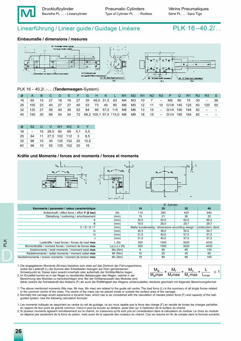
Linearführung / Linear guide / Guidage Linéaire PLK 16 –40.2/ . .Einbaumaße / dimensions / mesures
PLK 16 – 40.2/..-.... (Tandemwagen-System)ø A B C D E F G H K L M1 M2 N1 N2 N3 P Q R1 R2 R3 S16 65 15 27 18 18 27 35 48,5 31,5 63 M4 M3 10 7 – M5 90 70 30 – 3625 100 23 40 27 27 40 53 73 40 80 M6 M5 12 11 10 G1/8 145 125 60 120 5032 125 27 56 40 36 52 64 90 57,5 115 M8 M6 13 15 – G1/4 190 164 82 – –40 150 30 69 54 54 72 69,2 105,1 57,5 115,0 M8 M6 18 15 – G1/4 190 164 82 – –
ø S2 U V W1 W2 X Y16 – 10 28,5 60 69 5,1 5,525 64 11 27,5 102 112 3 8,532 96 10 30 135 152 20 10,540 96 10 55 135 152 20 16
D
PLK
1. Die angegebenen Momente (M.max) beziehen sich stets auf das Zentrum der Führungsschiene,wobei die Lastkraft (L) die Summe aller Einzellasten bezogen auf ihren gemeinsamenSchwerpunkt ist. Dieser kann sowohl innerhalb oder außerhalb der Schlittenfläche liegen.
2. Im Einzelfall kommt es in der Regel zu resultierden Belastungen des Wagen, welche in derBerechnung des Modules zu berücksichtigen sind. Bei der Größenauswahl des Modules sinddaher sowohl die Antriebskraft des Kolbens (F) als auch die Rollfähigkeit des Wagens sicherzustellen; letzteres geschieht mit folgender Berechnungsformel:
1. The above mentioned moments (Ma max, Mr max, Mv max) are related to the guide rail centre. The load force (L) is the summary of all single forces relatedto the common centre of the mass. The centre of the mass can be placed inside or outside the surface area of the carriage.
2. Normally the carriage would experience a dynamic load, which has to be considered with the calculation of needed piston force (F) and capacity of the ball-guided system. Use the following calculation formular:
1. Les moments indiqués se rapportent au centre du rail de guidage, ce qui nous rapelle que la force des charge (F) en resulte de toutes les charges partiellesen rapport de leur point de gravité commun. Celui-ci peut se trouver au dedans, aussi bien qu' á l'exterieur de la surface du chariot.
2. Si plusieur moments agissent simultanement sur le chariot, on s'assurera qu'ils sont pris en considération dans la calculation du module. Le choix du modulene dépend pas seulement de la force du piston, mais aussi de la capacité des rouleaux du chariot. Ceci se resume en fin de compte dans la formule suivante:
Ø ZylinderKennwerte / parameter / valeur caracteristique 16 25 32 40
Kolbenkraft / effect force / effort F (6 bar) (N) 110 250 420 640Dämpfung / custioning / amortissement (mm) 15 21 26 32
A (mm) 35,0 53,0 64,0 69,2B (mm) 19,0 26,0 29,7 29,7
C / D / E / F (mm) Maße kundenseitig / dimensions according design / construction clientG (mm) 30,3 38,0 55,0 54,7H (mm) 31,5 40,0 57,5 57,5J (mm) 31,5 40,0 57,5 57,5
Lastkräfte / load forces / forces de load max L (N) 500 1550 3020 4030Momentkräfte / moment forces / moment de forces max La,Lr,Lv (N) 500 1550 3020 4030
Axialmonente / axial moments / momoent axial max Ma (Nm) 8 85 85 130Radialmomente / radial moments / moment radial max Mr (Nm) 10 20 45 65
Verdrehmomente / torsion moments / moment de torsion max Mv (Nm) 18 80 90 100
Ma Mr Mv LMamax Mrmax Mvmax Lmax
� 1+ + +
Kräfte und Momente / forces and moments / forces et moments
Medan-Katalog_neu_2-2009.qxd 26.02.2009 16:44 Uhr Seite 26
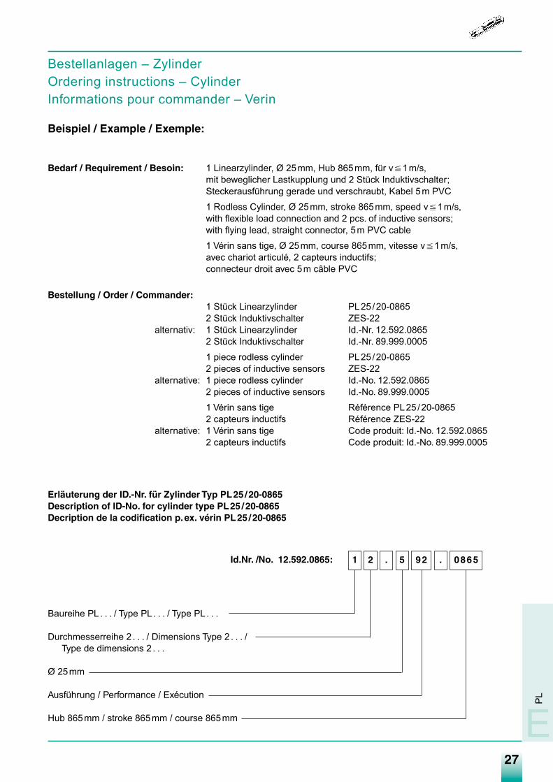
Bestellanlagen – ZylinderOrdering instructions – CylinderInformations pour commander – Verin
Beispiel / Example / Exemple:
Bedarf / Requirement / Besoin: 1 Linearzylinder, Ø 25mm, Hub 865mm, für v�1m/s,mit beweglicher Lastkupplung und 2 Stück Induktivschalter;Steckerausführung gerade und verschraubt, Kabel 5m PVC
1 Rodless Cylinder, Ø 25mm, stroke 865mm, speed v�1m/s,with flexible load connection and 2 pcs. of inductive sensors;with flying lead, straight connector, 5m PVC cable
1 Vérin sans tige, Ø 25mm, course 865mm, vitesse v�1m/s,avec chariot articulé, 2 capteurs inductifs;connecteur droit avec 5m câble PVC
Bestellung / Order / Commander:1 Stück Linearzylinder PL25/20-08652 Stück Induktivschalter ZES-22
alternativ: 1 Stück Linearzylinder Id.-Nr. 12.592.08652 Stück Induktivschalter Id.-Nr. 89.999.0005
1 piece rodless cylinder PL25/20-08652 pieces of inductive sensors ZES-22
alternative: 1 piece rodless cylinder Id.-No. 12.592.08652 pieces of inductive sensors Id.-No. 89.999.0005
1 Vérin sans tige Référence PL25 /20-08652 capteurs inductifs Référence ZES-22
alternative: 1 Vérin sans tige Code produit: Id.-No. 12.592.08652 capteurs inductifs Code produit: Id.-No. 89.999.0005
Erläuterung der ID.-Nr. für Zylinder Typ PL25/20-0865Description of ID-No. for cylinder type PL25/20-0865Decription de la codification p.ex. vérin PL25/20-0865
Id.Nr. /No. 12.592.0865:
Baureihe PL . . . / Type PL . . . / Type PL . . .
Durchmesserreihe 2 . . . / Dimensions Type 2 . . . /Type de dimensions 2 . . .
Ø 25mm
Ausführung / Performance / Exécution
Hub 865mm / stroke 865mm / course 865mm
0865.925.21
27
PL
E
Medan-Katalog_neu_2-2009.qxd 26.02.2009 16:44 Uhr Seite 27
28
Druckluftzylinder Pneumatic Cylinders Vérins PneumatiquesBaureihe PL … - Linearzylinder Type of Cylinder PL … - Rodless Série PL …- Sans Tige
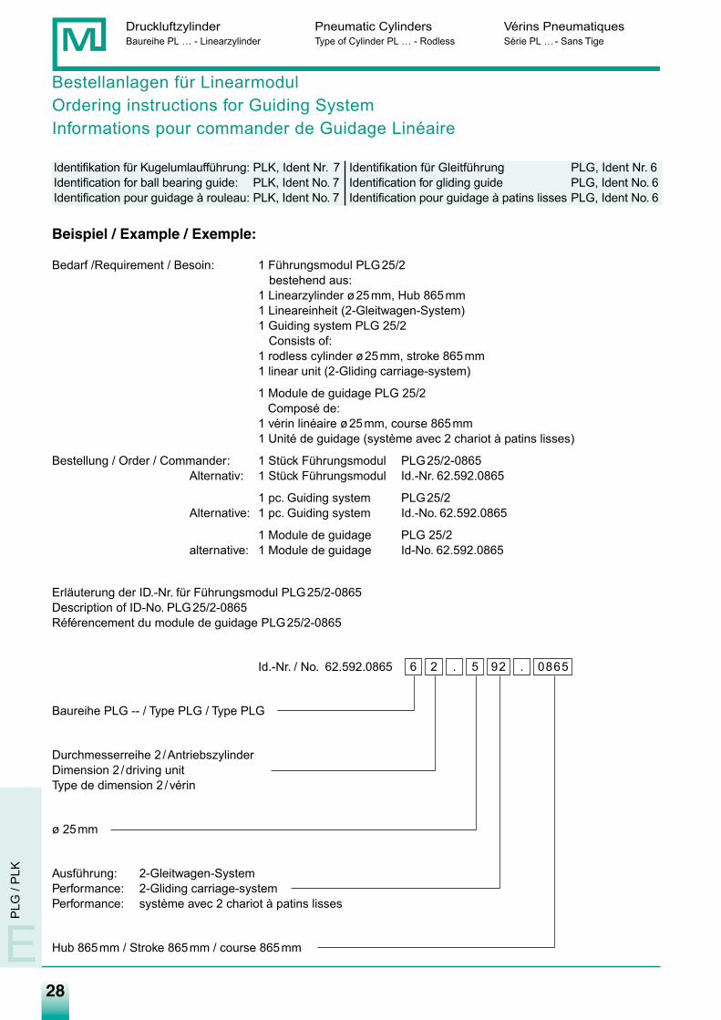
Bestellanlagen für LinearmodulOrdering instructions for Guiding SystemInformations pour commander de Guidage Linéaire
Identifikation für Kugelumlaufführung: PLK, Ident Nr. 7 Identifikation für Gleitführung PLG, Ident Nr. 6Identification for ball bearing guide: PLK, Ident No. 7 Identification for gliding guide PLG, Ident No. 6Identification pour guidage à rouleau: PLK, Ident No. 7 Identification pour guidage à patins lisses PLG, Ident No. 6
Beispiel / Example / Exemple:
Bedarf /Requirement / Besoin: 1 Führungsmodul PLG25/2bestehend aus:
1 Linearzylinder ø25mm, Hub 865mm1 Lineareinheit (2-Gleitwagen-System)1 Guiding system PLG 25/2
Consists of:1 rodless cylinder ø25mm, stroke 865mm 1 linear unit (2-Gliding carriage-system)
1 Module de guidage PLG 25/2Composé de:
1 vérin linéaire ø25mm, course 865mm1 Unité de guidage (système avec 2 chariot à patins lisses)
Bestellung / Order / Commander: 1 Stück Führungsmodul PLG25/2-0865Alternativ: 1 Stück Führungsmodul Id.-Nr. 62.592.0865
1 pc. Guiding system PLG25/2Alternative: 1 pc. Guiding system Id.-No. 62.592.0865
1 Module de guidage PLG 25/2alternative: 1 Module de guidage Id-No. 62.592.0865
Erläuterung der ID.-Nr. für Führungsmodul PLG25/2-0865Description of ID-No. PLG25/2-0865Référencement du module de guidage PLG25/2-0865
Id.-Nr. / No. 62.592.0865
Baureihe PLG -- / Type PLG / Type PLG
Durchmesserreihe 2 /AntriebszylinderDimension 2 /driving unitType de dimension 2 /vérin
ø 25mm
Ausführung: 2-Gleitwagen-SystemPerformance: 2-Gliding carriage-systemPerformance: système avec 2 chariot à patins lisses
Hub 865mm / Stroke 865mm / course 865mm
0865.925.26
E
PLG
/ P
LK
Medan-Katalog_neu_2-2009.qxd 26.02.2009 16:44 Uhr Seite 28
29
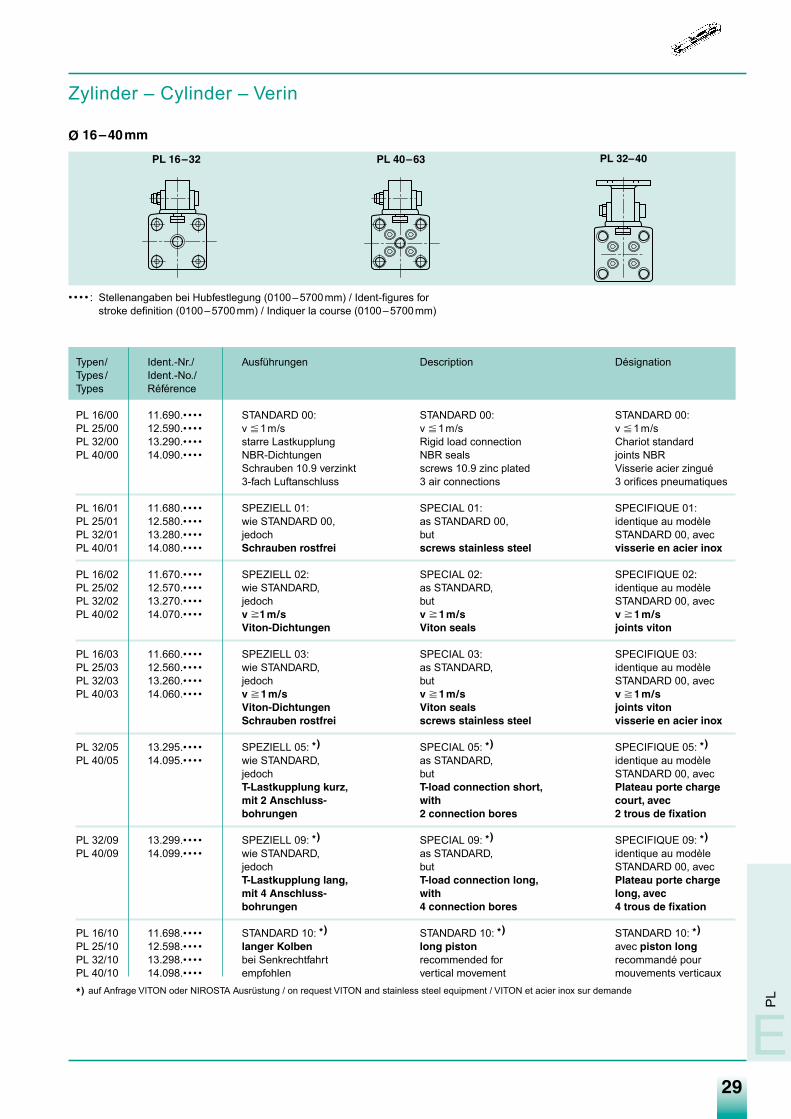
Zylinder – Cylinder – Verin
Ø 16–40mm
• • • • : Stellenangaben bei Hubfestlegung (0100–5700mm) / Ident-figures forstroke definition (0100–5700mm) / Indiquer la course (0100–5700mm)
Typen/ Ident.-Nr./ Ausführungen Description DésignationTypes / Ident.-No./Types Référence
PL 16/00 11.690.• • • • STANDARD 00: STANDARD 00: STANDARD 00:PL 25/00 12.590.• • • • v �1m/s v �1m/s v �1m/sPL 32/00 13.290.• • • • starre Lastkupplung Rigid load connection Chariot standardPL 40/00 14.090.• • • • NBR-Dichtungen NBR seals joints NBRPL 50/00 15.090.• • • • Schrauben 10.9 verzinkt screws 10.9 zinc plated Visserie acier zinguéPL 63/00 16.390.• • • • 3-fach Luftanschluss 3 air connections 3 orifices pneumatiques
PL 16/01 11.680.• • • • SPEZIELL 01: SPECIAL 01: SPECIFIQUE 01:PL 25/01 12.580.• • • • wie STANDARD 00, as STANDARD 00, identique au modèlePL 32/01 13.280.• • • • jedoch but STANDARD 00, avecPL 40/01 14.080.• • • • Schrauben rostfrei screws stainless steel visserie en acier inox
PL 16/02 11.670.• • • • SPEZIELL 02: SPECIAL 02: SPECIFIQUE 02:PL 25/02 12.570.• • • • wie STANDARD, as STANDARD, identique au modèlePL 32/02 13.270.• • • • jedoch but STANDARD 00, avecPL 40/02 14.070.• • • • v �1m/s v �1m/s v �1m/sPL 50/02 15.070.• • • • Viton-Dichtungen Viton seals joints viton
PL 16/03 11.660.• • • • SPEZIELL 03: SPECIAL 03: SPECIFIQUE 03:PL 25/03 12.560.• • • • wie STANDARD, as STANDARD, identique au modèlePL 32/03 13.260.• • • • jedoch but STANDARD 00, avecPL 40/03 14.060.• • • • v �1m/s v �1m/s v �1m/sPL 50/03 15.060.• • • • Viton-Dichtungen Viton seals joints vitonPL 63/03 16.360.• • • • Schrauben rostfrei screws stainless steel visserie en acier inox
PL 32/05 13.295.• • • • SPEZIELL 05: *) SPECIAL 05: *) SPECIFIQUE 05: *)
PL 40/05 14.095.• • • • wie STANDARD, as STANDARD, identique au modèlejedoch but STANDARD 00, avecT-Lastkupplung kurz, T-load connection short, Plateau porte chargemit 2 Anschluss- with court, avecbohrungen 2 connection bores 2 trous de fixation
PL 32/09 13.299.• • • • SPEZIELL 09: *) SPECIAL 09: *) SPECIFIQUE 09: *)
PL 40/09 14.099.• • • • wie STANDARD, as STANDARD, identique au modèlejedoch but STANDARD 00, avecT-Lastkupplung lang, T-load connection long, Plateau porte chargemit 4 Anschluss- with long, avecbohrungen 4 connection bores 4 trous de fixation
PL 16/10 11.698.• • • • STANDARD 10: *) STANDARD 10: *) STANDARD 10: *)
PL 25/10 12.598.• • • • langer Kolben long piston avec piston longPL 32/10 13.298.• • • • bei Senkrechtfahrt recommended for recommandé pourPL 40/10 14.098.• • • • empfohlen vertical movement mouvements verticaux
*) auf Anfrage VITON oder NIROSTA Ausrüstung / on request VITON and stainless steel equipment / VITON et acier inox sur demande
PL 16–32 PL 40–63
PL
E
PL 32–40
Medan-Katalog_neu_2-2009.qxd 26.02.2009 16:44 Uhr Seite 29
30
Druckluftzylinder Pneumatic Cylinders Vérins PneumatiquesBaureihe PL … - Linearzylinder Type of Cylinder PL … - Rodless Série PL …- Sans Tige
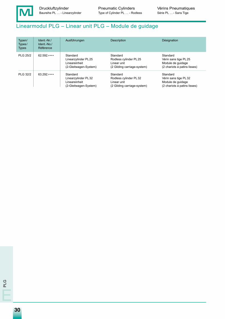
Linearmodul PLG – Linear unit PLG – Module de guidage
Typen/ Ident.-Nr./ Ausführungen Description DésignationTypes / Ident.-No./Types Référence
PLG 25/2 62.592.• • • • Standard Standard StandardLinearzylinder PL25 Rodless cylinder PL25 Vérin sans tige PL25Lineareinheit Linear unit Module de guidage(2-Gleitwagen-System) (2 Gliding carriage-system) (2 chariots à patins lisses)
PLG 32/2 63.292.• • • • Standard Standard StandardLinearzylinder PL32 Rodless cylinder PL32 Vérin sans tige PL32Lineareinheit Linear unit Module de guidage(2-Gleitwagen-System) (2 Gliding carriage-system) (2 chariots à patins lisses)
E
PLG
Medan-Katalog_neu_2-2009.qxd 26.02.2009 16:44 Uhr Seite 30
31
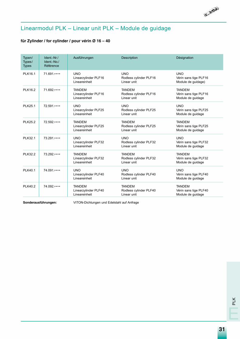
Linearmodul PLK – Linear unit PLK – Module de guidage
für Zylinder / for cylinder / pour vérin Ø 16 – 40
Typen/ Ident.-Nr./ Ausführungen Description DésignationTypes / Ident.-No./Types Référence
PLK16.1 71.691.• • • • UNO UNO UNOLinearzylinder PLF16 Rodless cylinder PLF16 Vérin sans tige PLF16Lineareinheit Linear unit Module de guidage)
PLK16.2 71.692.• • • • TANDEM TANDEM TANDEMLinearzylinder PLF16 Rodless cylinder PLF16 Vérin sans tige PLF16Lineareinheit Linear unit Module de guidage
PLK25.1 72.591.• • • • UNO UNO UNOLinearzylinder PLF25 Rodless cylinder PLF25 Vérin sans tige PLF25Lineareinheit Linear unit Module de guidage
PLK25.2 72.592.• • • • TANDEM TANDEM TANDEMLinearzylinder PLF25 Rodless cylinder PLF25 Vérin sans tige PLF25Lineareinheit Linear unit Module de guidage
PLK32.1 73.291.• • • • UNO UNO UNOLinearzylinder PLF32 Rodless cylinder PLF32 Vérin sans tige PLF32Lineareinheit Linear unit Module de guidage
PLK32.2 73.292.• • • • TANDEM TANDEM TANDEMLinearzylinder PLF32 Rodless cylinder PLF32 Vérin sans tige PLF32Lineareinheit Linear unit Module de guidage
PLK40.1 74.091.• • • • UNO UNO UNOLinearzylinder PLF40 Rodless cylinder PLF40 Vérin sans tige PLF40Lineareinheit Linear unit Module de guidage
PLK40.2 74.092.• • • • TANDEM TANDEM TANDEMLinearzylinder PLF40 Rodless cylinder PLF40 Vérin sans tige PLF40Lineareinheit Linear unit Module de guidage
Sonderausführungen: VITON-Dichtungen und Edelstahl auf Anfrage
PLK
E
Medan-Katalog_neu_2-2009.qxd 26.02.2009 16:44 Uhr Seite 31
32
Druckluftzylinder Pneumatic Cylinders Vérins PneumatiquesBaureihe PL …-Linearzylinder Type of Cylinder PL …-Rodless Série PL …Sans Tige
E
PL
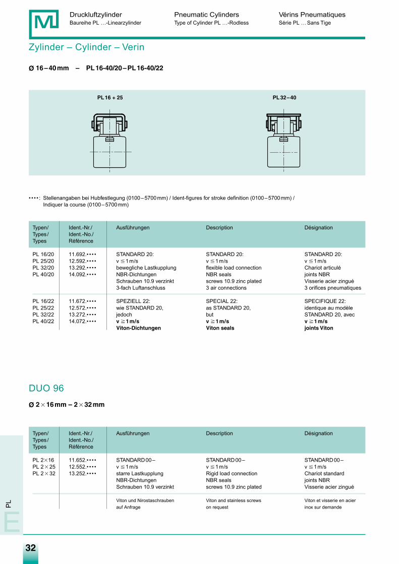
Zylinder – Cylinder – Verin
Ø 16–40mm – PL16-40/20–PL16-40/22
DUO 96
Ø 2�16mm – 2�32mm
• • • • : Stellenangaben bei Hubfestlegung (0100–5700mm) / Ident-figures for stroke definition (0100–5700mm) /Indiquer la course (0100–5700mm)
Typen/ Ident.-Nr./ Ausführungen Description DésignationTypes / Ident.-No./Types Référence
PL 16/20 11.692.• • • • STANDARD 20: STANDARD 20: STANDARD 20:PL 25/20 12.592.• • • • v �1m/s v �1m/s v �1m/sPL 32/20 13.292.• • • • bewegliche Lastkupplung flexible load connection Chariot articuléPL 40/20 14.092.• • • • NBR-Dichtungen NBR seals joints NBRPL 50/20 15.092.• • • • Schrauben 10.9 verzinkt screws 10.9 zinc plated Visserie acier zinguéPL 63/20 16.392.• • • • 3-fach Luftanschluss 3 air connections 3 orifices pneumatiques
PL 16/22 11.672.• • • • SPEZIELL 22: SPECIAL 22: SPECIFIQUE 22:PL 25/22 12.572.• • • • wie STANDARD 20, as STANDARD 20, identique au modèlePL 32/22 13.272.• • • • jedoch but STANDARD 20, avecPL 40/22 14.072.• • • • v �1m/s v �1m/s v �1m/sPL 50/22 15.072.• • • • Viton-Dichtungen Viton seals joints Viton
Typen/ Ident.-Nr./ Ausführungen Description DésignationTypes / Ident.-No./Types Référence
PL 2�16 11.652.• • • • STANDARD00– STANDARD00– STANDARD00–PL 2�25 12.552.• • • • v �1m/s v �1m/s v �1m/sPL 2�32 13.252.• • • • starre Lastkupplung Rigid load connection Chariot standard
NBR-Dichtungen NBR seals joints NBRSchrauben 10.9 verzinkt screws 10.9 zinc plated Visserie acier zingué
Viton und Nirostaschrauben Viton and stainless screws Viton et visserie en acierauf Anfrage on request inox sur demande
PL16 + 25 PL32–40
Medan-Katalog_neu_2-2009.qxd 26.02.2009 16:44 Uhr Seite 32
33
Bes
tellin
form
atio
nO
rder
ing
inst
ruct
ions
Info
rmat
ions
pou
r com
man
der
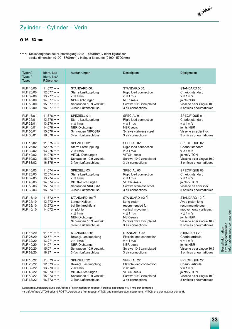
• • • • : Stellenangaben bei Hubfestlegung (0100–5700mm) / Ident-figures forstroke dimension (0100–5700mm) / Indiquer la course (0100–5700mm)
Typen/ Ident.-Nr./ Ausführungen Description DésignationTypes / Ident.-No./Types Référence
PLF 16/00 11.677.• • • • STANDARD 00: STANDARD 00: STANDARD 00:PLF 25/00 12.577.• • • • Starre Lastkupplung Rigid load connection Chariot standardPLF 32/00 13.277.• • • • v �1m/s v �1m/s v �1m/sPLF 40/00 14.077.• • • • NBR-Dichtungen NBR seals joints NBRPLF 50/00 15.077.• • • • Schrauben 10.9 verzinkt Screws 10.9 zinc plated Visserie acier zingué 10.9PLF 63/00 16.377.• • • • 3-fach Luftanschluss 3 air connections 3 orifices pneumatiques
PLF 16/01 11.676.• • • • SPEZIELL 01: SPECIAL 01: SPECIFIQUE 01:PLF 25/01 12.576.• • • • Starre Lastkupplung Rigid load connection Chariot standardPLF 32/01 13.276.• • • • v �1m/s v �1m/s v �1m/sPLF 40/01 14.076.• • • • NBR-Dichtungen NBR seals joints NBRPLF 50/01 15.076.• • • • Schrauben NIROSTA Screws stainless steel Visserie en acier inoxPLF 63/01 16.376.• • • • 3-fach Luftanschluss 3 air connections 3 orifices pneumatiques
PLF 16/02 11.675.• • • • SPEZIELL 02: SPECIAL 02: SPECIFIQUE 02:PLF 25/02 12.575.• • • • Starre Lastkupplung Rigid load connection Chariot standardPLF 32/02 13.275.• • • • v �1m/s v �1m/s v �1m/sPLF 40/02 14.075.• • • • VITON-Dichtungen VITON-seals joints VITONPLF 50/02 15.075.• • • • Schrauben 10.9 verzinkt Screws 10.9 zinc plated Visserie acier zingué 10.9PLF 63/02 16.375.• • • • 3-fach Luftanschluss 3 air connections 3 orifices pneumatiques
PLF 16/03 11.674.• • • • SPEZIELL 03: SPECIAL 03: SPECIFIQUE 03:PLF 25/03 12.574.• • • • Starre Lastkupplung Rigid load connection Chariot standardPLF 32/03 13.274.• • • • v �1m/s v �1m/s v �1m/sPLF 40/03 14.074.• • • • VITON-Dichtungen VITON-seals joints VITONPLF 50/03 15.074.• • • • Schrauben NIROSTA Screws stainless steel Visserie en acier inoxPLF 63/03 16.374.• • • • 3-fach Luftanschluss 3 air connections 3 orifices pneumatiques
PLF 16/10 11.672.• • • • STANDARD 10: *) STANDARD 10: *) STANDARD 10: *)PLF 25/10 12.572.• • • • Langer Kolben Long piston Avec piston longPLF 32/10 13.272.• • • • bei Senkrechtfahrt recommended for recommandé pourPLF 40/10 14.072.• • • • empfohlen vertical movement mouvements verticaux
v �1m/s v �1m/s v �1m/sNBR-Dichtungen NBR-seals joints NBRSchrauben 10.9 verzinkt Screws 10.9 zinc plated Visserie acier zingué 10.93-fach Luftanschluss 3 air connections 3 orifices pneumatiques
PLF 16/20 11.671.• • • • STANDARD 20: STANDARD 20: STANDARD 20:PLF 25/20 12.571.• • • • Bewegl. Lastkupplung Flexible load connection Chariot articuléPLF 32/20 13.271.• • • • v �1m/s v �1m/s v �1m/sPLF 40/20 14.071.• • • • NBR-Dichtungen NBR-seals joints NBRPLF 50/20 15.071.• • • • Schrauben 10.9 verzinkt Screws 10.9 zinc plated Visserie acier zingué 10.9PLF 63/20 16.371.• • • • 3-fach Luftanschluss 3 air connections 3 orifices pneumatiques
PLF 16/22 11.673.• • • • SPEZIELL 22: SPECIAL 22: SPECIFIQUE 22:PLF 25/22 12.573.• • • • Bewegl. Lastkupplung Flexible load connection Chariot articuléPLF 32/22 13.273.• • • • v �1m/s v �1m/s v �1m/sPLF 40/22 14.073.• • • • VITON-Dichtungen VITON-seals joints VITONPLF 50/22 15.073.• • • • Schrauben 10.9 verzinkt Screws 10.9 zinc plated Visserie acier zingué 10.9PLF 63/22 16.373.• • • • 3-fach Luftanschluss 3 air connections 3 orifices pneumatiques
Langsamlauffettausrüstung auf Anfrage / slow motion on request / graisse spécifique v �1m/s sur démande
*) auf Anfrage VITON oder NIROSTA Ausrüstung / on request VITON and stainless steel equipment / VITON et acier inox sur demande
Zylinder – Cylinder – Verin
Ø 16–63mm
Medan-Katalog_neu_2-2009.qxd 26.02.2009 16:44 Uhr Seite 33
34
Bestellinform
ationO
rdering instructionsInform
ations pour comm
ander
Druckluftzylinder Pneumatic Cylinders Vérins PneumatiquesBaureihe PL …-Linearzylinder Type of Cylinder PL …-Rodless Série PL …Sans Tige
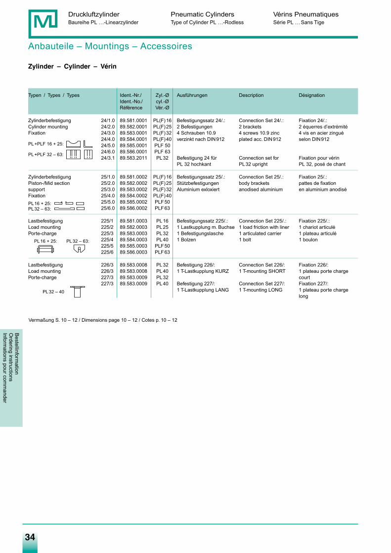
Anbauteile – Mountings – Accessoires
Zylinder – Cylinder – Vérin
Typen / Types / Types Ident.-Nr./ Zyl.-Ø Ausführungen Description DésignationIdent.-No./ cyl.-ØRéférence Vér.-Ø
Zylinderbefestigung 24/1.0 89.581.0001 PL(F)16 Befestigungssatz 24/.: Connection Set 24/.: Fixation 24/.:Cylinder mounting 24/2.0 89.582.0001 PL(F)25 2 Befestigungen 2 brackets 2 équerres d’extrémitéFixation 24/3.0 89.583.0001 PL(F)32 4 Schrauben 10.9 4 screws 10.9 zinc 4 vis en acier zingué
24/4.0 89.584.0001 PL(F)40 verzinkt nach DIN912 plated acc. DIN912 selon DIN91224/5.0 89.585.0001 PLF 5024/6.0 89.586.0001 PLF 6324/3.1 89.583.2011 PL32 Befestigung 24 für Connection set for Fixation pour vérin
PL 32 hochkant PL32 upright PL 32, posé de chant
Zylinderbefestigung 25/1.0 89.581.0002 PL(F)16 Befestigungssatz 25/.: Connection Set 25/.: Fixation 25/.:Piston-/Mid section 25/2.0 89.582.0002 PL(F)25 Stützbefestigungen body brackets pattes de fixationsupport 25/3.0 89.583.0002 PL(F)32 Aluminium exloxiert anodised aluminium en aluminium anodiséFixation 25/4.0 89.584.0002 PL(F)40
25/5.0 89.585.0002 PLF5025/6.0 89.586.0002 PLF63
Lastbefestigung 225/1 89.581.0003 PL16 Befestigungssatz 225/.: Connection Set 225/.: Fixation 225/.:Load mounting 225/2 89.582.0003 PL25 1 Lastkupplung m. Buchse 1 load friction with liner 1 chariot articuléPorte-charge 225/3 89.583.0003 PL32 1 Befestigungslasche 1 articulated carrier 1 plateau articulé
225/4 89.584.0003 PL40 1 Bolzen 1 bolt 1 boulon225/5 89.585.0003 PLF50225/6 89.586.0003 PLF63
Lastbefestigung 226/3 89.583.0008 PL32 Befestigung 226/: Connection Set 226/: Fixation 226/:Load mounting 226/3 89.583.0008 PL40 1 T-Lastkupplung KURZ 1 T-mounting SHORT 1 plateau porte chargePorte-charge 227/3 89.583.0009 PL32 court
227/3 89.583.0009 PL40 Befestigung 227/: Connection Set 227/: Fixation 227/:1 T-Lastkupplung LANG 1 T-mounting LONG 1 plateau porte charge
long
PL+PLF 16 + 25:
PL+PLF 32 – 63:
PL16 + 25:
PL32 – 40
PL32 – 63:
PL16 + 25:PL32 – 63:
Vermaßung S. 10 – 12 / Dimensions page 10 – 12 / Cotes p. 10 – 12
Medan-Katalog_neu_2-2009.qxd 26.02.2009 16:44 Uhr Seite 34
35
PL
/ PLF
E
Anbauteile – Mountings – Accessoires
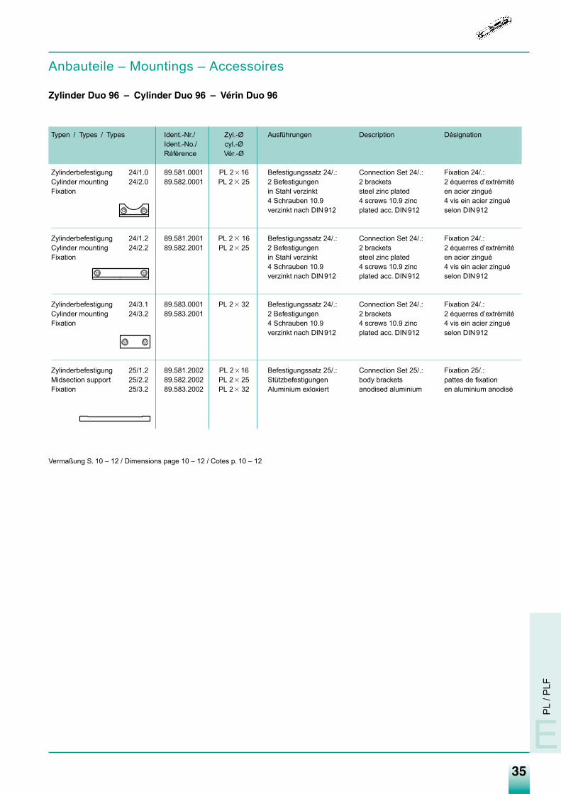
Zylinder Duo 96 – Cylinder Duo 96 – Vérin Duo 96
Typen / Types / Types Ident.-Nr./ Zyl.-Ø Ausführungen Description DésignationIdent.-No./ cyl.-ØRéférence Vér.-Ø
Zylinderbefestigung 24/1.0 89.581.0001 PL 2�16 Befestigungssatz 24/.: Connection Set 24/.: Fixation 24/.:Cylinder mounting 24/2.0 89.582.0001 PL 2� 25 2 Befestigungen 2 brackets 2 équerres d’extrémitéFixation in Stahl verzinkt steel zinc plated en acier zingué
4 Schrauben 10.9 4 screws 10.9 zinc 4 vis ein acier zinguéverzinkt nach DIN912 plated acc. DIN912 selon DIN912
Zylinderbefestigung 24/1.2 89.581.2001 PL 2� 16 Befestigungssatz 24/.: Connection Set 24/.: Fixation 24/.:Cylinder mounting 24/2.2 89.582.2001 PL 2� 25 2 Befestigungen 2 brackets 2 équerres d’extrémitéFixation in Stahl verzinkt steel zinc plated en acier zingué
4 Schrauben 10.9 4 screws 10.9 zinc 4 vis ein acier zinguéverzinkt nach DIN912 plated acc. DIN912 selon DIN912
Zylinderbefestigung 24/3.1 89.583.0001 PL 2� 32 Befestigungssatz 24/.: Connection Set 24/.: Fixation 24/.:Cylinder mounting 24/3.2 89.583.2001 2 Befestigungen 2 brackets 2 équerres d’extrémitéFixation 4 Schrauben 10.9 4 screws 10.9 zinc 4 vis ein acier zingué
verzinkt nach DIN912 plated acc. DIN912 selon DIN912
Zylinderbefestigung 25/1.2 89.581.2002 PL 2�16 Befestigungssatz 25/.: Connection Set 25/.: Fixation 25/.:Midsection support 25/2.2 89.582.2002 PL 2� 25 Stützbefestigungen body brackets pattes de fixationFixation 25/3.2 89.583.2002 PL 2� 32 Aluminium exloxiert anodised aluminium en aluminium anodisé
Vermaßung S. 10 – 12 / Dimensions page 10 – 12 / Cotes p. 10 – 12
Medan-Katalog_neu_2-2009.qxd 26.02.2009 16:44 Uhr Seite 35
36
Druckluftzylinder Pneumatic Cylinders Vérins PneumatiquesBaureihe PL … - Linearzylinder Type of Cylinder PL … - Rodless Série PL …- Sans Tige
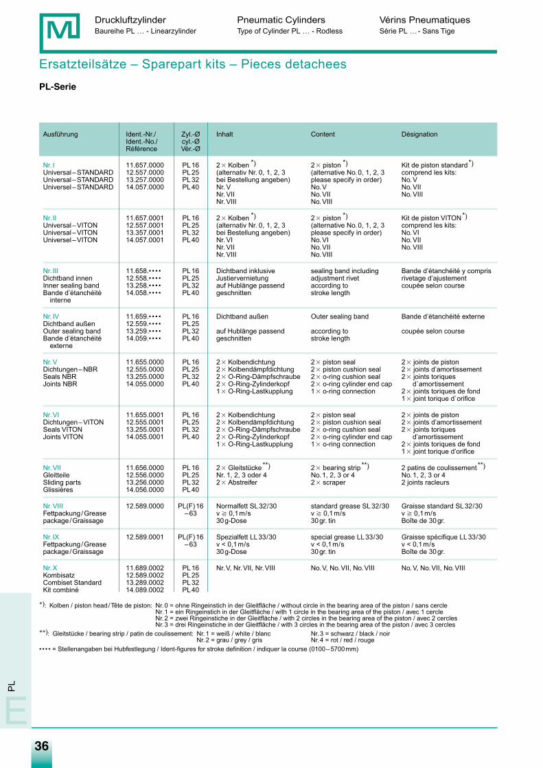
Ersatzteilsätze – Sparepart kits – Pieces detachees
PL-Serie
Ausführung Ident.-Nr./ Zyl.-Ø Inhalt Content DésignationIdent.-No./ cyl.-ØRéférence Vér.-Ø
Nr. I 11.657.0000 PL16 2� Kolben *) 2� piston *) Kit de piston standard*)Universal–STANDARD 12.557.0000 PL25 (alternativ Nr. 0, 1, 2, 3 (alternative No.0, 1, 2, 3 comprend les kits:Universal–STANDARD 13.257.0000 PL32 bei Bestellung angeben) please specify in order) No.VUniversel–STANDARD 14.057.0000 PL40 Nr. V No.V No.VII
Nr. VII No.VII No.VIIINr. VIII No.VIII
Nr. II 11.657.0001 PL16 2� Kolben *) 2� piston *) Kit de piston VITON*)Universal–VITON 12.557.0001 PL25 (alternativ Nr. 0, 1, 2, 3 (alternative No.0, 1, 2, 3 comprend les kits:Universal–VITON 13.357.0001 PL32 bei Bestellung angeben) please specify in order) No.VIUniversel–VITON 14.057.0001 PL40 Nr. VI No.VI No.VII
Nr. VII No.VII No.VIIINr. VIII No.VIII
Nr. III 11.658.• • • • PL16 Dichtband inklusive sealing band including Bande d’étanchéité y comprisDichtband innen 12.558.• • • • PL25 Justiervernietung adjustment rivet rivetage d’ajustementInner sealing band 13.258.• • • • PL32 auf Hublänge passend according to coupée selon courseBande d’étanchéité 14.058.• • • • PL40 geschnitten stroke length
interne
Nr. IV 11.659.• • • • PL16 Dichtband außen Outer sealing band Bande d’étanchéité externeDichtband außen 12.559.• • • • PL25Outer sealing band 13.259.• • • • PL32 auf Hublänge passend according to coupée selon courseBande d’étanchéité 14.059.• • • • PL40 geschnitten stroke length
externe
Nr.V 11.655.0000 PL16 2� Kolbendichtung 2� piston seal 2� joints de pistonDichtungen–NBR 12.555.0000 PL25 2� Kolbendämpfdichtung 2� piston cushion seal 2� joints d’amortissementSeals NBR 13.255.0000 PL32 2� O-Ring-Dämpfschraube 2� o-ring cushion seal 2� joints toriques Joints NBR 14.055.0000 PL40 2� O-Ring-Zylinderkopf 2� o-ring cylinder end cap d`amortissement
1� O-Ring-Lastkupplung 1� o-ring connection 2� joints toriques de fond1� joint torique d`orifice
Nr.VI 11.655.0001 PL16 2� Kolbendichtung 2� piston seal 2� joints de pistonDichtungen–VITON 12.555.0001 PL25 2� Kolbendämpfdichtung 2� piston cushion seal 2� joints d’amortissementSeals VITON 13.255.0001 PL32 2� O-Ring-Dämpfschraube 2� o-ring cushion seal 2� joints toriquesJoints VITON 14.055.0001 PL40 2� O-Ring-Zylinderkopf 2� o-ring cylinder end cap d’amortissement
1� O-Ring-Lastkupplung 1� o-ring connection 2� joints toriques de fond1� joint torique d’orifice
Nr.VII 11.656.0000 PL16 2� Gleitstücke**) 2� bearing strip **) 2 patins de coulissement **)Gleitteile 12.556.0000 PL25 Nr. 1, 2, 3 oder 4 No.1, 2, 3 or 4 No.1, 2, 3 or 4Sliding parts 13.256.0000 PL32 2� Abstreifer 2� scraper 2 joints racleursGlissières 14.056.0000 PL40
Nr.VIII 12.589.0000 PL(F)16 Normalfett SL32/30 standard grease SL32/30 Graisse standard SL32/30Fettpackung /Grease –63 v � 0,1m/s v � 0,1m/s v � 0,1m/spackage /Graissage 30g-Dose 30gr. tin Boîte de 30gr.
Nr. IX 12.589.0001 PL(F)16 Spezialfett LL33/30 special grease LL33/30 Graisse spécifique LL33/30Fettpackung /Grease –63 v < 0,1m/s v < 0,1m/s v < 0,1m/spackage /Graissage 30g-Dose 30gr. tin Boîte de 30gr.
Nr.X 11.689.0002 PL16 Nr.V, Nr.VII, Nr.VIII No.V, No.VII, No.VIII No.V, No.VII, No.VIIIKombisatz 12.589.0002 PL25Combiset Standard 13.289.0002 PL32Kit combiné 14.089.0002 PL40
∗): Kolben / piston head /Tête de piston: Nr.0 = ohne Ringeinstich in der Gleitfläche / without circle in the bearing area of the piston / sans cercleNr.1 = ein Ringeinstich in der Gleitfläche / with 1 circle in the bearing area of the piston / avec 1 cercleNr.2 = zwei Ringeinstiche in der Gleitfläche / with 2 circles in the bearing area of the piston / avec 2 cerclesNr.3 = drei Ringeinstiche in der Gleitfläche / with 3 circles in the bearing area of the piston / avec 3 cercles
∗∗): Gleitstücke / bearing strip / patin de coulissement: Nr.1 = weiß / white / blanc Nr.3 = schwarz / black / noirNr.2 = grau / grey / gris Nr.4 = rot / red / rouge
• • • • = Stellenangaben bei Hubfestlegung / Ident-figures for stroke definition / indiquer la course (0100–5700mm)
E
PL
Medan-Katalog_neu_2-2009.qxd 26.02.2009 16:44 Uhr Seite 36
37
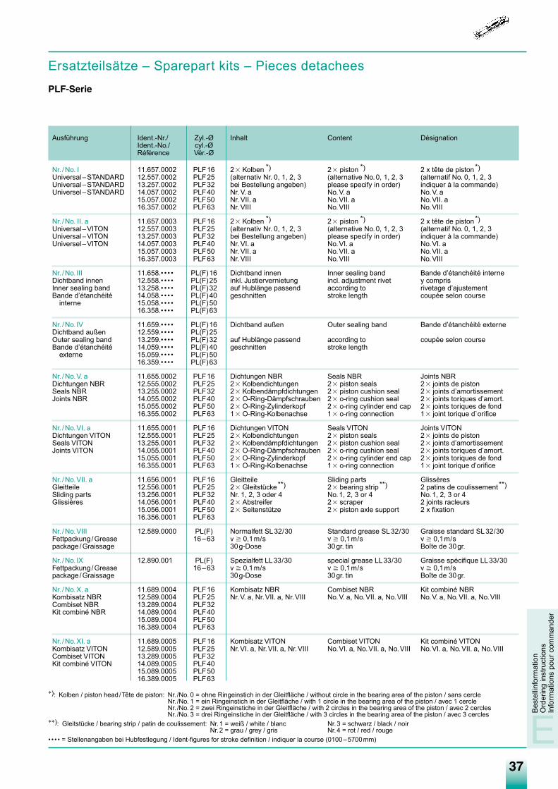
Ersatzteilsätze – Sparepart kits – Pieces detachees
PLF-Serie
Bes
tellin
form
atio
nO
rder
ing
inst
ruct
ions
Info
rmat
ions
pou
r com
man
der
E
Ausführung Ident.-Nr./ Zyl.-Ø Inhalt Content DésignationIdent.-No./ cyl.-ØRéférence Vér.-Ø
Nr. /No. I 11.657.0002 PLF16 2� Kolben *) 2� piston *) 2 x tête de piston*)Universal–STANDARD 12.557.0002 PLF25 (alternativ Nr. 0, 1, 2, 3 (alternative No.0, 1, 2, 3 (alternatif No. 0, 1, 2, 3Universal–STANDARD 13.257.0002 PLF32 bei Bestellung angeben) please specify in order) indiquer à la commande)Universel–STANDARD 14.057.0002 PLF40 Nr. V. a No.V. a No.V. a
15.057.0002 PLF50 Nr. VII. a No.VII. a No.VII. a16.357.0002 PLF63 Nr. VIII No.VIII No.VIII
Nr. /No. II. a 11.657.0003 PLF16 2� Kolben *) 2� piston *) 2 x tête de piston*)Universal–VITON 12.557.0003 PLF25 (alternativ Nr. 0, 1, 2, 3 (alternative No.0, 1, 2, 3 (alternatif No. 0, 1, 2, 3Universal–VITON 13.257.0003 PLF32 bei Bestellung angeben) please specify in order) indiquer à la commande)Universel–VITON 14.057.0003 PLF40 Nr. VI. a No.VI. a No.VI. a
15.057.0003 PLF50 Nr. VII. a No.VII. a No.VII. a16.357.0003 PLF63 Nr. VIII No.VIII No.VIII
Nr. /No. III 11.658.• • • • PL(F)16 Dichtband innen Inner sealing band Bande d’étanchéité interneDichtband innen 12.558.• • • • PL(F)25 inkl. Justiervernietung incl. adjustment rivet y comprisInner sealing band 13.258.• • • • PL(F)32 auf Hublänge passend according to rivetage d’ajustement Bande d’étanchéité 14.058.• • • • PL(F)40 geschnitten stroke length coupée selon course
interne 15.058.• • • • PL(F)5016.358.• • • • PL(F)63
Nr. /No. IV 11.659.• • • • PL(F)16 Dichtband außen Outer sealing band Bande d’étanchéité externeDichtband außen 12.559.• • • • PL(F)25Outer sealing band 13.259.• • • • PL(F)32 auf Hublänge passend according to coupée selon courseBande d’étanchéité 14.059.• • • • PL(F)40 geschnitten stroke length
externe 15.059.• • • • PL(F)5016.359.• • • • PL(F)63
Nr. /No.V. a 11.655.0002 PLF16 Dichtungen NBR Seals NBR Joints NBRDichtungen NBR 12.555.0002 PLF25 2� Kolbendichtungen 2� piston seals 2� joints de pistonSeals NBR 13.255.0002 PLF32 2� Kolbendämpfdichtungen 2� piston cushion seal 2� joints d’amortissement Joints NBR 14.055.0002 PLF40 2� O-Ring-Dämpfschrauben 2� o-ring cushion seal 2� joints toriques d’amort.
15.055.0002 PLF50 2� O-Ring-Zylinderkopf 2� o-ring cylinder end cap 2� joints toriques de fond16.355.0002 PLF63 1� O-Ring-Kolbenachse 1� o-ring connection 1� joint torique d`orifice
Nr. /No.VI. a 11.655.0001 PLF16 Dichtungen VITON Seals VITON Joints VITONDichtungen VITON 12.555.0001 PLF25 2� Kolbendichtungen 2� piston seals 2� joints de pistonSeals VITON 13.255.0001 PLF32 2� Kolbendämpfdichtungen 2� piston cushion seal 2� joints d’amortissementJoints VITON 14.055.0001 PLF40 2� O-Ring-Dämpfschrauben 2� o-ring cushion seal 2� joints toriques d’amort.
15.055.0001 PLF50 2� O-Ring-Zylinderkopf 2� o-ring cylinder end cap 2� joints toriques de fond16.355.0001 PLF63 1� O-Ring-Kolbenachse 1� o-ring connection 1� joint torique d’orifice
Nr. /No.VII. a 11.656.0001 PLF16 Gleitteile Sliding parts Glissères Gleitteile 12.556.0001 PLF25 2� Gleitstücke**) 2� bearing strip **) 2 patins de coulissement **)Sliding parts 13.256.0001 PLF32 Nr. 1, 2, 3 oder 4 No.1, 2, 3 or 4 No.1, 2, 3 or 4Glissières 14.056.0001 PLF40 2� Abstreifer 2� scraper 2 joints racleurs
15.056.0001 PLF50 2� Seitenstütze 2� piston axle support 2 x fixation16.356.0001 PLF63
Nr. /No.VIII 12.589.0000 PL(F) Normalfett SL32/30 Standard grease SL32/30 Graisse standard SL32/30Fettpackung /Grease 16–63 v � 0,1m/s v � 0,1m/s v � 0,1m/spackage /Graissage 30g-Dose 30gr. tin Boîte de 30gr.
Nr. /No. IX 12.890.001 PL(F) Spezialfett LL33/30 special grease LL33/30 Graisse spécifique LL33/30Fettpackung /Grease 16–63 v � 0,1m/s v � 0,1m/s v � 0,1m/spackage /Graissage 30g-Dose 30gr. tin Boîte de 30gr.
Nr. /No.X. a 11.689.0004 PLF16 Kombisatz NBR Combiset NBR Kit combiné NBRKombisatz NBR 12.589.0004 PLF25 Nr.V. a, Nr.VII. a, Nr.VIII No.V. a, No.VII. a, No.VIII No.V. a, No.VII. a, No.VIIICombiset NBR 13.289.0004 PLF32Kit combiné NBR 14.089.0004 PLF40
15.089.0004 PLF5016.389.0004 PLF63
Nr. /No.XI. a 11.689.0005 PLF16 Kombisatz VITON Combiset VITON Kit combiné VITONKombisatz VITON 12.589.0005 PLF25 Nr.VI. a, Nr.VII. a, Nr.VIII No.VI. a, No.VII. a, No.VIII No.VI. a, No.VII. a, No.VIIICombiset VITON 13.289.0005 PLF32Kit combiné VITON 14.089.0005 PLF40
15.089.0005 PLF5016.389.0005 PLF63
∗): Kolben / piston head /Tête de piston: Nr. /No. 0 = ohne Ringeinstich in der Gleitfläche / without circle in the bearing area of the piston / sans cercleNr. /No. 1 = ein Ringeinstich in der Gleitfläche / with 1 circle in the bearing area of the piston / avec 1 cercleNr. /No. 2 = zwei Ringeinstiche in der Gleitfläche / with 2 circles in the bearing area of the piston / avec 2 cerclesNr. /No. 3 = drei Ringeinstiche in der Gleitfläche / with 3 circles in the bearing area of the piston / avec 3 cercles
∗∗): Gleitstücke / bearing strip / patin de coulissement: Nr.1 = weiß / white / blanc Nr.3 = schwarz / black / noirNr.2 = grau / grey / gris Nr.4 = rot / red / rouge
• • • • = Stellenangaben bei Hubfestlegung / Ident-figures for stroke definition / indiquer la course (0100–5700mm)
Medan-Katalog_neu_2-2009.qxd 26.02.2009 16:44 Uhr Seite 37
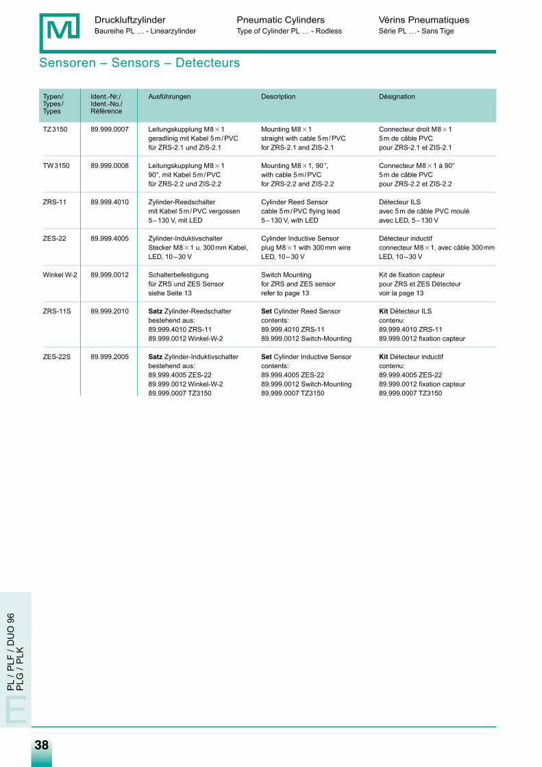
38
Druckluftzylinder Pneumatic Cylinders Vérins PneumatiquesBaureihe PL … - Linearzylinder Type of Cylinder PL … - Rodless Série PL …- Sans Tige
E
PL
/PLF
/D
UO
96
PLG
/P
LK
Sensoren – Sensors – Detecteurs
Typen/ Ident.-Nr./ Ausführungen Description DésignationTypes / Ident.-No./Types Référence
TZ3150 89.999.0007 Leitungskupplung M8�1 Mounting M8�1 Connecteur droit M8�1geradlinig mit Kabel 5m/PVC straight with cable 5m/PVC 5m de câble PVCfür ZRS-2.1 und ZIS-2.1 for ZRS-2.1 and ZIS-2.1 pour ZRS-2.1 et ZIS-2.1
TW3150 89.999.0008 Leitungskupplung M8�1 Mounting M8�1, 90°, Connecteur M8�1 à 90°90°, mit Kabel 5m/PVC with cable 5m/PVC 5m de câble PVCfür ZRS-2.2 und ZIS-2.2 for ZRS-2.2 and ZIS-2.2 pour ZRS-2.2 et ZIS-2.2
ZRS-11 89.999.4010 Zylinder-Reedschalter Cylinder Reed Sensor Détecteur ILSmit Kabel 5m/PVC vergossen cable 5m/PVC flying lead avec 5m de câble PVC moulé5–130 V, mit LED 5–130 V, with LED avec LED, 5–130 V
ZES-22 89.999.4005 Zylinder-Induktivschalter Cylinder Inductive Sensor Détecteur inductifStecker M8�1 u. 300mm Kabel, plug M8�1 with 300mm wire connecteur M8�1, avec câble 300mmLED, 10–30 V LED, 10–30 V LED, 10–30 V
Winkel W-2 89.999.0012 Schalterbefestigung Switch Mounting Kit de fixation capteurfür ZRS und ZES Sensor for ZRS and ZES sensor pour ZRS et ZES Détecteursiehe Seite 13 refer to page 13 voir la page 13
ZRS-11S 89.999.2010 Satz Zylinder-Reedschalter Set Cylinder Reed Sensor Kit Détecteur ILSbestehend aus: contents: contenu:89.999.4010 ZRS-11 89.999.4010 ZRS-11 89.999.4010 ZRS-1189.999.0012 Winkel-W-2 89.999.0012 Switch-Mounting 89.999.0012 fixation capteur
ZES-22S 89.999.2005 Satz Zylinder-Induktivschalter Set Cylinder Inductive Sensor Kit Détecteur inductifbestehend aus: contents: contenu:89.999.4005 ZES-22 89.999.4005 ZES-22 89.999.4005 ZES-2289.999.0012 Winkel-W-2 89.999.0012 Switch-Mounting 89.999.0012 fixation capteur89.999.0007 TZ3150 89.999.0007 TZ3150 89.999.0007 TZ3150
Medan-Katalog_neu_2-2009.qxd 26.02.2009 16:44 Uhr Seite 38
39
Notizen
Medan-Katalog_neu_2-2009.qxd 26.02.2009 16:44 Uhr Seite 39
40
Notizen
Medan-Katalog_neu_2-2009.qxd 26.02.2009 16:44 Uhr Seite 40


WWIIRR BBEEWWEEGGEENN LLIINNEEAARRWWIIRR BBEEWWEEGGEENN LLIINNEEAARR
DEUTSCHLAND SÜD-OSTISB Industrievertretung Siegfried Bauer Moorenweiser Str. 33 D-82299 Türkenfeld Tel.: +49(0)8193.8262 Fax: +49(0)8193.4183 e-mail: [email protected] www.isb-industrievertretung.de
DEUTSCHLAND MITTE-WESTTechnischer Handel Schenk Im Grund 5 D-34613 Schwalmstadt Tel.: +49(0)6691.5744 Fax: +49(0)6691.72156 e-mail: [email protected] www.ths-industriebedarf.de
DEUTSCHLAND SÜD-WESTIndustrievertretung Dirk Rönnfeldt Lindpaintnerstr. 86 D-70195 Stuttgart Tel.: +49(0)711.69 47 00 Fax: +49(0)711.69 60 470 e-mail: [email protected]
DEUTSCHLAND MITTERossbach & Sonnenhol GmbH Hohe Steinert 31 D-58509 LüdenscheidTel.: +49(0)2351.6 72 69-0Fax: +49(0)2351.6 72 69-26e-mail: [email protected] www.rossbach-sonnenhol.de
DEUTSCHLAND NORDFREISE GmbH Justus-von-Liebig-Ring 7-9 D-25451 QuickbornTel.: +49(0)4106.7 60 67-0Fax: +49(0)4106.7 60 67-10e-mail: [email protected] www.freise-automation.de
DEUTSCHLAND NORD-OSTIAM Industrievertretung Alfred MeyerAn der Lake 6D-39114 MagdeburgTel.: +49 (0) 391.8118837Fax: +49 (0) 391.8118838e-mail: [email protected]
DEUTSCHLAND WESTMüller Maschinentechnik GmbH Moltkestr. 15 D-52351 Düren Tel.: +49(0)2421.4 95 48-0 Fax: +49(0)2421.4 95 48-11e-mail: [email protected] www.mueller-maschinentechnik.de
BENELUXALFA Techniek B.V.Rondebeltweg 32NL-1329 BB AlmereTel.: +31 (0) 36 5 38 733 33Fax: +31 (0) 36 5 38 733 44e-mail: [email protected]
DÄNEMARKFritz Schur Teknik AS Sydmarken 46 DK-2860 Soborg Tel.: +45(0)70 20 16 16 Fax: +45(0)70 20 16 11 e-mail: [email protected] www.pneumatik.dk
ENGLANDPSI Pneumatic SolutionsInternational Ltd.Unit 8 Stratfield Electra AveWaterloovilleHants PO7 7XNTel.: +44 (0) 2392 233611Fax: +44 (0) 2392 [email protected]
CANADATopAir Industry Co. Ltd. Unit #4, Hedgedale RoadBrampton Ontario L6T5P3CANADA Tel: +1(0)416 736 7480 Fax: +1(0)416 736 7481 e-mail: [email protected]
IRANSherkate Tolid Lavazan MadarPneumatic Hydraulic Badran Co.139, Forsate Shirazi St.North Navvab Ave.Tehran 14197Tel.: +98 (0) 021 66 92 2170Fax: +98 (0) 21 66 92 90 04e-mail: [email protected]
MALAYSIAT&K Pneumatic Sdn BhdNo 2-C-3, Tingkat KenariSungai Ara 11900 Penang / Malaysia Tel.: +604 641 23 88 Fax: +604 641 43 88 e-mail: [email protected]
POLENElektro-Automatic S.C. ul. Elizy Orzeszkowej 64 05/820 Piastów Tel.: +48/22/753-94-79 Fax: +48/22/723-15-43 e-mail: [email protected] www.elektro-automatic.com.pl
SINGAPURE - F L O W Asia PTE Ltd.BIK 201 Henderson Road #03-05Henderson Industrial Park159545 SingaporeTel.: +65 6836 9343Fax: +65 6736 2682e-mail: [email protected]
THAILANDT.V.P. Valves & Pneumatics Co. Ltd.a 89 Soi Ramindra 52/1Kannayao, KannnayaoBangkok 10230Tel.: +662 948 5040-4Fax: +662 948 5045e-mail: [email protected]
FINNLANDKnorring OY AB Kavaarmokuja 6 SF-003800 Helsinki Tel.: +35(0)5 60 41 Fax: +35(0)565 24 63
FRANKREICHMultiTech SARLLa technique au service de l’industrie 5 rue des Sarcelles F-67300 Schiltigheim Tel.: +33(0)3 88 20 04 17 Fax: +33(0)3 88 20 92 81 e-mail: [email protected]
ITALIENITEKA SNCVia Rinaldini 62I-25020 Flero (BS)Tel.: +39 (0) 30 2761 630Fax: +39 (0) 30 2563 095e-mail: [email protected]
ÖSTERREICHAgentur AC Automation ComponentsIng. Thomas NeuhauserWiener Str. 59A-2104 SpillernTel.: +43 (0) 2266.81257Fax: +43 (0) 2266.80161e-mail: [email protected]
SCHWEDEN ILogicsystem ABBORAS Industrigation 22, 504 63 BorasTel.: +46(0)33 10 04 70Fax: +46(0)33 10 80 31e-mail: [email protected]
SCHWEDEN IILogicsystem AB HELSINGBORG Lilla Garnisionsgatan 35 254 67 Helsingborg Tel.: +46(0)42 38 61 50 Fax: +46(0)42 20 18 97 e-mail: [email protected] www. logicsystemab.com
SCHWEIZ IStefisa 30, Chemin l’Arzelier CH-1071 Chexbres Tel.: +41(0)219 46 40 44 Fax: +41(0)219 46 40 45 e-mail: [email protected] www.stefisa.ch
SCHWEIZ IIWoelfel AG Quellenweg 11/PF42 CH-4912 Aarwangen Tel.: +41(0)62 922 48 88 Fax: +41(0) 62 922 63 70 e-mail: [email protected]
SPANIENComercial Leku-Ona S.L. Poligono Industrial Arriaga, 9,Apa rtado 41 E-20870 ELGOIBAR-Guipuzcoa Tel.: +34 (0)943 743 450 Fax: +34(0) 943 743 462 e-mail: [email protected]
TÜRKEIHIDRO-TEK Ltd. STI ISTOC Ticaret Merkezi 8. Ada No:160 34217 Mahmutbey Istanbul/Turkei Tel : +90 (0) 212 659 86 36 Fax: +90 (0) 212 659 86 39 email: [email protected] www.hidro-tek.com.tr
MEDAN Verkaufsorganisation / sales organization
www.medan-gmbh.com
MEDAN GMBHAuf dem Brühl 672658 BempflingenTel.: +49 (0) 7123 32402Fax: +49 (0) 7123 36580E-Mail: [email protected]
Medan_Produktkatalog_U4_neu_2-2009_Ausg.indd 1Medan_Produktkatalog_U4_neu_2-2009_Ausg.indd 1 25.02.2009 9:21:54 Uhr25.02.2009 9:21:54 Uhr