MGC 282685 Tiresca TE.qxp:MGC 28xxxx Tiresca TE
8
Tiresca ® -Schienensystem für Innenraum- und Freiluftanwendungen vollisoliert Typ TEL / Um ≤ 1 – 3,6 kV teilisoliert Typ TE / Um ≥ 3,6 – 36 kV Tiresca ® busbar system for indoor and outdoor applications fully insulated Type TEL / Um ≤ 1 – 3,6 kV partially insulated Type TE / Um ≥ 3,6 – 36 kV Système de barres Tiresca ® pour des applications intérieures et extérieures totalement isolé Type TEL / Um ≤ 1 – 3,6 kV partiellement isolé Type TE / Um ≥ 3,6 – 36 kV
Transcript of MGC 282685 Tiresca TE.qxp:MGC 28xxxx Tiresca TE
Tiresca®-Schienensystemfür Innenraum- und Freiluftanwendungenvollisoliert Typ TEL / Um ≤1– 3,6 kVteilisoliert Typ TE / Um ≥ 3,6 – 36 kV
Tiresca® busbar systemfor indoor and outdoor applicationsfully insulated Type TEL / Um ≤1 – 3,6 kVpartially insulated Type TE / Um ≥ 3,6 – 36 kV
Système de barres Tiresca®
pour des applications intérieures et extérieurestotalement isolé Type TEL / Um ≤1– 3,6 kVpartiellement isolé Type TE / Um ≥ 3,6 – 36 kV

2
Unsere ProduktpaletteProduct rangeNotre gamme de produits
DTOI 123 kV – 1250 A
Travesca®
Transformator-DurchführungTransformer bushingTraversées pour transformateur
Tiresca®
SchienensystemBusbar systemSystèmes de barres
TE 24 kV – 1250 A
Duresca®
WanddurchführungenWall bushingsTraversées murales
DM2I 36 kV – 1600 A
Duresca®
SchienensystemBusbar systemSystèmes de barres
DE 17,5 kV – 2500 A
GL 12 kV – 2500 A
Gaslink®
SF6 isoliertes SchienensystemSF6 insulated busbar systemsSystèmes de barres isolé au SF6
3
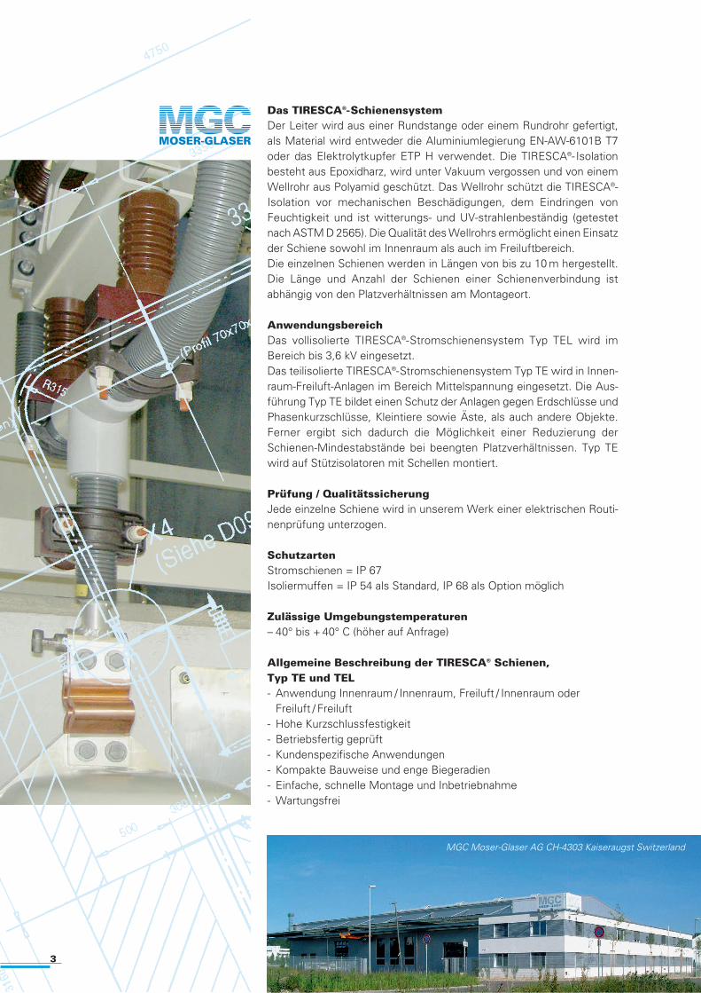
Das TIRESCA®-SchienensystemDer Leiter wird aus einer Rundstange oder einem Rundrohr gefertigt,als Material wird entweder die Aluminiumlegierung EN-AW-6101B T7oder das Elektrolytkupfer ETP H verwendet. Die TIRESCA®- Isolation besteht aus Epoxidharz, wird unter Vakuum vergossen und von einemWellrohr aus Polyamid geschützt. Das Wellrohr schützt die TIRESCA®-Isolation vor mechanischen Beschädigungen, dem Eindringen vonFeuchtigkeit und ist witterungs- und UV-strahlenbeständig (getestetnach ASTM D 2565). Die Qualität des Wellrohrs ermöglicht einen Einsatzder Schiene sowohl im Innenraum als auch im Freiluftbereich.Die einzelnen Schienen werden in Längen von bis zu 10 m hergestellt.Die Länge und Anzahl der Schienen einer Schienenverbindung ist abhängig von den Platzverhältnissen am Montageort.
AnwendungsbereichDas vollisolierte TIRESCA®-Stromschienensystem Typ TEL wird im Bereich bis 3,6 kV eingesetzt.Das teilisolierte TIRESCA®-Stromschienensystem Typ TE wird in Innen-raum-Freiluft-Anlagen im Bereich Mittelspannung eingesetzt. Die Aus-führung Typ TE bildet einen Schutz der Anlagen gegen Erdschlüsse undPhasenkurzschlüsse, Kleintiere sowie Äste, als auch andere Objekte.Ferner ergibt sich dadurch die Möglichkeit einer Reduzierung derSchienen-Mindestabstände bei beengten Platzverhältnissen. Typ TEwird auf Stützisolatoren mit Schellen montiert.
Prüfung / Qualitätssicherung Jede einzelne Schiene wird in unserem Werk einer elektrischen Routi-nenprüfung unterzogen.
SchutzartenStromschienen = IP 67Isoliermuffen = IP 54 als Standard, IP 68 als Option möglich
Zulässige Umgebungstemperaturen– 40° bis + 40° C (höher auf Anfrage)
Allgemeine Beschreibung der TIRESCA® Schienen, Typ TE und TEL- Anwendung Innenraum / Innenraum, Freiluft / Innenraum oder
Freiluft / Freiluft- Hohe Kurzschlussfestigkeit- Betriebsfertig geprüft- Kundenspezifische Anwendungen - Kompakte Bauweise und enge Biegeradien- Einfache, schnelle Montage und Inbetriebnahme- Wartungsfrei
MGC Moser-Glaser AG CH-4303 Kaiseraugst Switzerland
4
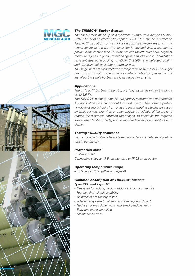
The TIRESCA® Busbar SystemThe conductor is made up of a cylindrical aluminium alloy type EN AW-6101B T7, or of an electrolytic copper E Cu ETP H. The direct attachedTIRESCA® insulation consists of a vacuum cast epoxy resin. On thewhole lenght of the bar, the insulation is covered with a corrugatedpolyamide protection tube.This tube provides an effective barrier againstmoisture ingress, a good protection against shocks and is UV radiationresistant (tested according to ASTM D 2565). The selected quality authorizes as well an indoor or outdoor use.The single bars are manufactured in lenghts up to 10 meters. For longerbus runs or by tight place conditions where only short pieces can be installed, the single busbars are joined together on site.
ApplicationsThe TIRESCA® busbars, type TEL, are fully insulated within the rangeup to 3,6 kV.The TIRESCA® busbars, type TE, are partially insulated and designed forMV applications in indoor or outdoor switchyards. They offer a protec-tion against short circuits from phase to earth and phase to phase causedby small animals, branches or other objects. An additional feature is toreduce the distances between the phases, to minimise the requiredspace when limited. The type TE is mounted on support insulators withclamp.
Testing / Quality assuranceEach individual busbar is being tested according to an electrical routinetest in our factory.
Protection classBusbars: IP 67Connecting sleeves: IP 54 as standard or IP 68 as an option
Operating temperature range– 40° C up to 40° C (other on request)
Common description of TIRESCA® busbars, type TEL and type TE- Designed for indoor, indoor-outdoor and outdoor service- Highest short-circuit capability- All busbars are factory tested- Adaptable system for all new and existing switchyard- Reduced overall dimensions and small bending radius- Easy and fast assembling- Maintenance free

5
Le système de barres TIRESCA®
Le conducteur est soit en alliage d’aluminium EN AW-6101B T7 ou encuivre électrolytique E Cu ETP H. Il est de forme tubulaire ou plein. Il estenrobé sous vide par une résine epoxy formant l’isolation TIRESCA®.Une enveloppe de protection en polyamide testé selon ASTM, épousetoute la longueur de la gaine. Elle forme une barrière efficace contre lapénétration de l’humidité, elle protège contre les chocs et résiste auxrayons UV (testé selon ASTM D 2565). La qualité retenue autorise uneutilisation tant en service intérieur que extérieur.Les barres sont fabriquées en longueurs jusqu’à 10 mètres. Lorsque lesliaisons à réaliser sont plus longues ou lorsqu’un impératif de montagel’impose, les barres sont assemblées entre elles.
Domaine d’applicationLes barres TIRESCA® du type TEL, à isolation totale, sont utilisées jusqu’à 3,6 kV.Les barres TIRESCA® du type TE, à isolation partielle, sont destinées àune installation tant en service intérieur que extérieur et utilisées en M.T.Elles offrent une protection contre les risques de court-circuit phase-terre ou entre-phases dues aux petits animaux, branches d’arbres ouautres mais permettent également une réduction de la distance entre-phases lorsqu’un faible encombrement est requis. Le type TE seramonté sur des isolateurs support.
Essais / Assurance qualitéChaque barre sera soumise, en usine, à un essai diélectrique.
Degré de protectionBarres: IP 67Manchon de jonction: IP 54 en standard, IP 68 en option
Température ambiante– 40° C à + 40° C (autre sur demande)
Descriptif commun des barres TIRESCA®, type TE et type TEL- Applications tant en service intérieur, que extérieur – intérieur, ou
extérieur- Grande tenue aux courants de court-circuit- Toutes les barres sont fabriquées et essayées diélectriquement en
usine - Système TIRESCA® adapatable à toutes les configurations de jeux
de barres, tant pour les installations neuves que existantes- Encombrement réduit et faibles rayons de courbure- Montage facile et rapide- Sans entretien
6
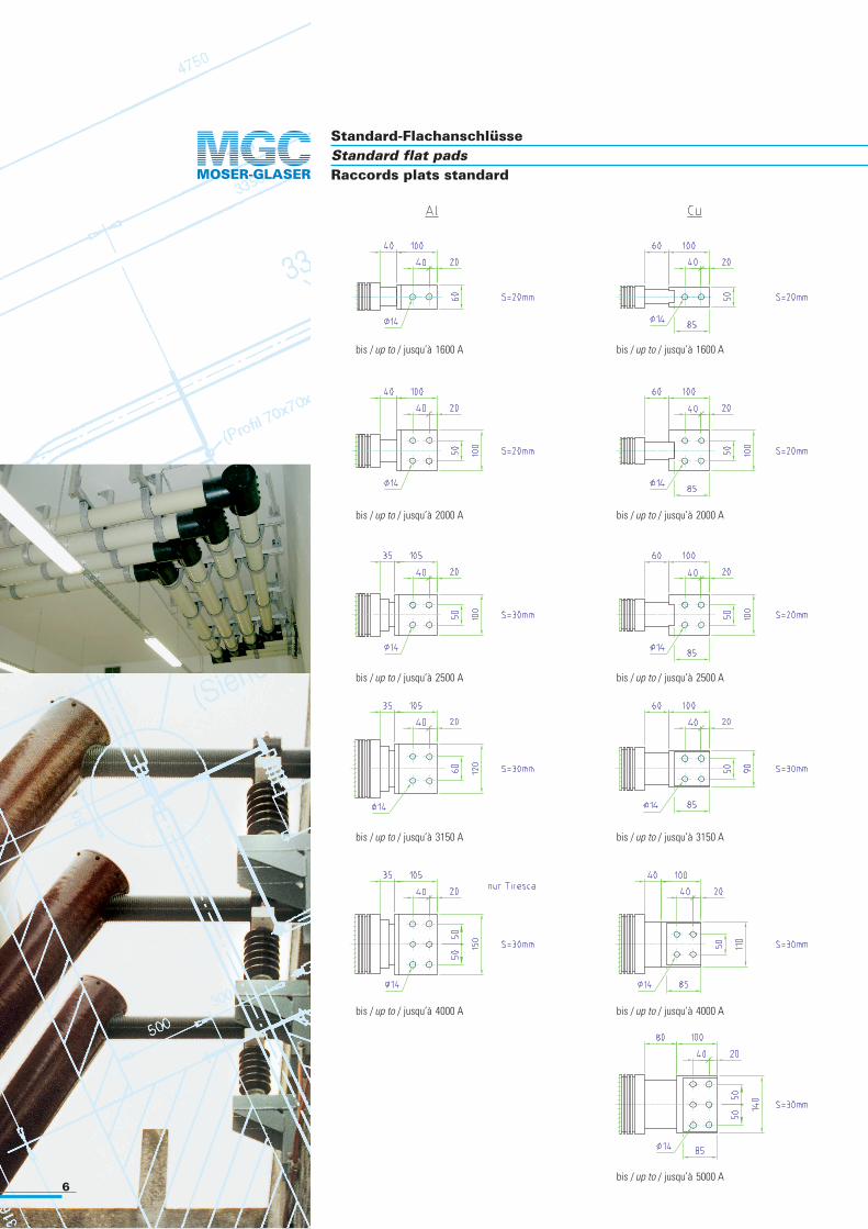
Standard-FlachanschlüsseStandard flat padsRaccords plats standard
bis / up to / jusqu’à 1600 A
bis / up to / jusqu’à 2000 A
bis / up to / jusqu’à 2500 A bis / up to / jusqu’à 2500 A
bis / up to / jusqu’à 3150 A
bis / up to / jusqu’à 4000 A
bis / up to / jusqu’à 1600 A
bis / up to / jusqu’à 2000 A
bis / up to / jusqu’à 3150 A
bis / up to / jusqu’à 4000 A
bis / up to / jusqu’à 5000 A

7
Technische DatenTechnical dataCaractéristiques techniques
TIRESCA: vollisoliert / fully insulated / totalement isoléStandard IEC 60439Ur: kV 1Up: kV 6
Leiter Aussen Leiter Biegeradius GewichtConductor Outer Conductor Bend radius Weight
Typ Ir: A PA ∅ mm ∅ mm Min. mm kg/m
TEL 1250 Al 55 36 250 4,1TEL 1250 Al 55 36 250 4,1TEL 1600 Al 67 45 250 6,2TEL 2000 Al 80 55 250 9,0TEL 2500 Al 106 80 / 50 400 12,0TEL 3150 Al 146 110 / 80 550 18,9TEL 4000 Al 146 120 / 90 550 17,6
TEL 1600 Cu 55 36 250 10,3TEL 2000 Cu 67 45 250 15,9TEL 2500 Cu 80 55 250 23,9TEL 3150 Cu 106 80 / 50 400 30,6TEL 4000 Cu 146 110 / 90 550 34,7TEL 5000 Cu 146 120 / 90 550 48,1
TIRESCA: vollisoliert / fully insulated / totalement isoléStandard IEC 60466Ur: kV 3,6Up: kV 10U Bil: kV 40
Leiter Aussen Leiter Biegeradius GewichtConductor Outer Conductor Bend radius Weight
Typ Ir: A PA ∅ mm ∅ mm Min. mm kg/m
TEL 1250 Al 55 36 250 4,1TEL 1600 Al 67 45 250 6,2TEL 2000 Al 80 55 250 9,0TEL 2500 Al 106 80 / 50 400 12,0TEL 3150 Al 146 110 / 80 550 18,9
TEL 1600 Cu 55 36 250 10,3TEL 2000 Cu 67 45 250 15,9TEL 2500 Cu 80 55 250 23,9TEL 3150 Cu 106 80 / 50 400 30,6TEL 4000 Cu 146 110 / 90 550 34,7
TIRESCA: vollisoliert / fully insulated / totalement isoléTIRESCA: teilisoliert / partially insulated / partiellement isoléStandard IEC 60466Ur: kV ≥ 7,2Up: kV 28
Leiter Aussen Leiter Biegeradius GewichtConductor Outer Conductor Bend radius Weight
Typ Ir: A PA ∅ mm ∅ mm Min. mm kg/m
TE 1250 Al 55 36 250 4,1TE 1600 Al 67 45 250 6,2TE 2000 Al 80 55 250 9,0TE 2500 Al 106 80 / 50 400 12,0TE 3150 Al 146 110 / 80 550 18,9
TE 1600 Cu 55 36 250 10,3TE 2000 Cu 67 45 250 15,9TE 2500 Cu 80 55 250 23,9TE 3150 Cu 106 80 / 50 400 30,6TE 4000 Cu 146 110 / 90 550 34,7

MGC Moser-Glaser AGLerchenweg 21CH-4303 KaiseraugstSchweiz / Suisse / Switzerland
Telefon +41 61 467 6111Telefax +41 61 467 6110Internet www.mgc.ch E-Mail [email protected]
AnlagenbeispielExample of an installationExemple d’installation
Vertreten durch / Represented by / Représenté par:
Bälge Bellows Type TELSoufflets
d e f g Anzahl Löcher Schienen – ∅No. of holes Busbars – ∅
120 150 175 80 8 55 / 67 / 80160 200 220 80 8 106200 240 265 110 8 146
a b c Anzahl Löcher Schienen – ∅No. of holes Busbars – ∅
110 150 185 4 55 / 67 / 80130 160 200 4 106180 220 260 6 146
Schienen / Busbars – ∅ 55 / 67 / 80 / 106
Schienen / Busbars – ∅ 146
Dichtflansche Sealing flanges Type TELBrides d’étanchéité
Leiter blank mitConduct.bare with Conduct. nu avec
kV kV kV mm X mm Y mm *
12 28 75 120 50
17,5 38 95 160 70 76
24 50 125 220 100 130
36 70 170 320 145 230
* Y ist abhängig von der Anlagen KonfigurationY depends on plant designY dépend de la configuration de l’installation
Mindestabstände im Innenraum zwischen Phase-Phase / Phase-Erde Indoor minimum distances between Phase-Phase / Phase-earth Type TEDistances minimales à l’intérieur entre Phase-Phase / Phase-terre
Ur a kV mm
12 130
17,5 175
24 210
36 300
Stützisolator mit Schelle Support insulator with clamp Type TEIsolateur-support avec bride
Änderungen vorbehalten / Alterations reserved / Sous réserve de modifications Tiresca Ed 1.0 - 07/08