MHKT - BPT Group 24800700 06_09.pdf · Die Versorgung darf nur an einen einzigen Steckverbinder...
4
1 06.2009/24800700 MHKT BPT S.p.A. Via Cornia, 1 33079 Sesto al Reghena (PN)-Italy http: www.bpt.it e-mail: [email protected] 4 5 AL B + – MM 1 2 1 2 3
Transcript of MHKT - BPT Group 24800700 06_09.pdf · Die Versorgung darf nur an einen einzigen Steckverbinder...

1106.2009/24800700
MHKT
BPT S.p.A.Via Cornia, 133079 Sesto al Reghena (PN)-Italyhttp: www.bpt.ite-mail: [email protected]
4 5
AL
B
+ –
MM
1
2
1 2
3
2
I ISTRUZIONI PERL’INSTALLAZIONE
Supporto da tavolo MHKT per videoter-minale serie Mitho. Sganciare l’apparecchio dal supporto metallico, facendolo scorrere 2 su di esso dopo aver premuto il pulsante pla-stico 1 (fig. 1). Rimuovere le morsettiere del videoter-minale.Fissare il supporto metallico in dotazio-ne con il videoterminale Mitho al sup-porto da tavolo (fig. 2) utilizzando le viti in dotazione. Effettuati i collegamenti (fig. 3) (rispet-tando le figure riportate sul fondo in plastica) agganciare il videoterminale al supporto metallico come indicato in figura 4.
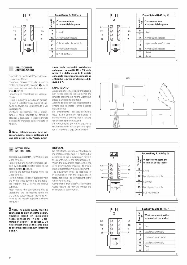
y Nota. L'alimentazione deve ne-cessariamente essere collegata ad una sola presa RJ45. Perciò, in fun-
zione delle necessità installative, collegare i morsetti TX e TS della presa 1 o della presa 2. È vietato collegarle contemporaneamente ad entrambe le prese evidenziate di fi-gura 6 e 7.
SMALTIMENTOAssicurarsi che il materiale d’imballaggio non venga disperso nell’ambiente, ma smaltito seguendo le norme vigenti nel paese di utilizzo del prodotto.Alla fine del ciclo di vita dell’apparecchio evitare che lo stesso venga disperso nell’ambiente.Lo smaltimento dell’apparecchiatura deve essere effettuato rispettando le norme vigenti e privilegiando il riciclag-gio delle sue parti costituenti.Sui componenti, per cui è previsto lo smaltimento con riciclaggio, sono ripor-tati il simbolo e la sigla del materiale.
GB INSTALLATIONINSTRUCTIONS
Tabletop support MHKT for Mitho series video terminal. Remove the unit from the metallic sup-port by sliding 2 on it after pressing the plastic button 1 (fig. 1).Remove the terminal boards from the video terminal.Fix the metallic support supplied with the Mitho video terminal to the table-top support (fig. 2) using the screws supplied. After making the connections (fig. 3) (observing the illustrations given on the plastic bottom) fasten the video ter-minal to the metallic support as shown in figure 4.
y Note. The power supply must be connected to only one RJ45 socket. However, based on installation needs, connect the TX and TS ter-minals of socket 1 or socket 2. Do not connect them at the same time to both the sockets shown in figures 6 and 7.
DISPOSALDo not litter the environment with pack-ing material: make sure it is disposed of according to the regulations in force in the country where the product is used.When the equipment reaches the end of its life cycle, take measures to ensure it is not discarded in the environment.The equipment must be disposed of in compliance with the regulations in force, recycling its component parts wherever possible.Components that qualify as recyclable waste feature the relevant symbol and the material’s abbreviation.
185
8
B
2
TX
L2
A
T
TS
L1
6
Presa/Spina RJ 45 (fig. 6)
Mor
sett
oPi
n Cosa connettere ai morsetti della presa
BLinea B
2
TX Alimentazione locale
L2Chiamata dal pianerottolo
L1
TS Alimentazione locale
TBUS MultiMaster
A
B
2
TX
L2
A
T
TS
L1
7
Presa/Spina RJ 45 (fig. 7)
Mor
sett
oPi
n Cosa connettere ai morsetti della presa
BLiberi
2
TX Alimentazione locale
L2Ingresso Allarme Comune
L1
TS Alimentazione locale
T Libero
A Libero
B
2
TX
L2
A
T
TS
L1
6
Socket/Plug RJ 45 (fig. 6)
Term
inal
Pin What to connect to the
terminals of the socket
BLine B
2
TX Local power supply
L2Doorbell
L1
TS Local power supply
TBUS MultiMaster
A
B
2
TX
L2
A
T
TS
L1
7
Socket/Plug RJ 45 (fig. 7)
Term
inal
Pin What to connect to the
terminals of the socket
BFree
2
TX Local power supply
L2Common alarm input
L1
TS Local power supply
T Free
A Free

3
DINSTALLATIONS-ANLEITUNG
Tischhalterung MHKT für Videoterminal Serie Mitho. Das Gerät an der Metallhalterung aus-hängen, in dem man es auf ihr ver-schiebt 2 nach dem man die Kunst-stofftaste 1 (Abb. 1)gedrückt hat. Die Klemmleisten des Videoterminals entfernen.Die beiliegende Metallhalterung mit dem Videoterminal Mitho mit den bei-liegenden Schrauben an der Tischhalte-rung (Abb. 2) befestigen. Nach den Anschlussarbeiten (Abb. 3) (die Abbildungen auf dem Kunststoff-boden beachten) das Videoterminal wie in der Abbildung 4 gezeigt, an der Me-tallhalterung einhängen.
y Hinweis. Die Versorgung darf nur an einen einzigen Steckverbinder RJ45 angeschlossen werden. Daher müssen je nach Installationsbedin-gungen die Klemmen TX und TS der Steckdose 1 oder 2 angeschlossen werden. Sie gleichzeitig an beide Steckdosen, die in den Abbildungen 6 und 7 gezeigt sind, anzuschließen, ist verboten.
ENTSORGUNGVergewissern Sie sich, dass das Verpa-ckungsmaterial gemäß den Vorschriften des Bestimmungslandes ordungsgemäß und umweltgerecht entsorgt wird.Das nicht mehr benutzbare Gerät ist umweltgerecht zu entsorgen.Die Entsorgung hat den geltenden Vorschriften zu entsprechen und vor-zugsweise das Recycling der Geräteteile vorzusehen.Die wiederverwertbaren Geräteteile sind mit einem Materialsym-bol und –zeichen versehen.
F INSTRUCTIONSPOUR L’INSTALLATION
Support de table MHKT pour écran ter-minal série Mitho. Retirer l'appareil du support métallique, en le faisant glisser 2 sur celui-ci après avoir appuyé sur le bouton en plastique 1 (fig. 1). Enlever les borniers de l'écran terminal.Fixer le support métallique fourni avec l'écran terminal Mitho au support de table (fig. 2) en utilisant les vis fournies. Une fois que les connexions ont été ef-fectuées (fig. 3) (en respectant les figures reportées sur le fond en plastique), fixer l'écran terminal au support métallique comme indiqué sur la figure 4.
y Note. L'alimentation doit néces-sairement être branchée à une seule prise RJ45. Par conséquent, en fonc-tion des nécessités d'installation, brancher les bornes TX et TS de la prise 1 ou de la prise 2. Il est interdit de les brancher simultanément aux deux prises mises en évidence aux figures 6 et 7.
ELIMINATIONS’assurer que le matériel d’emballage n’est pas abandonné dans la nature et qu’il est éliminé conformément aux nor-mes en vigueur dans le pays d’utilisation du produit. À la fin du cycle de vie de l’appareil, faire en sorte qu’il ne soit pas abandonné dans la nature. L’appareil doit être éliminé conformément aux normes en vigueur et en privilégiant le recyclage de ses pièces. Le symbole et le sigle du matériau sont indiqués sur les pièces pour lesquelles le recyclage est prévu.
B
2
TX
L2
A
T
TS
L1
6
Steckbuchse/Stecker RJ 45 (Abb. 6)
Kle
mm
ePi
n
Was an den Klemmen der Steckdose anzuschließen ist
BLeitung B
2
TX Lokale Stromversorgung
L2Anruf vom Treppenhaus
L1
TS Local power supply
TBUS MultiMaster
A
B
2
TX
L2
A
T
TS
L1
7
Steckbuchse/Stecker RJ 45 (Abb. 7)
Kle
mm
ePi
n
Was an den Klemmen der Steckdose anzuschließen ist
BFrei
2
TX Lokale Stromversorgung
L2Eingang allgemeiner Alarm
L1
TS Lokale Stromversorgung
T Frei
A Frei
B
2
TX
L2
A
T
TS
L1
6
Prise/Fiche RJ 45 (fig. 6)B
orn
eB
roch
eQue brancher aux bornes de la prise
BLigne B
2
TX Alimentation locale
L2Appel depuis le palier
L1
TS Alimentation locale
TBUS MultiMaster
A
B
2
TX
L2
A
T
TS
L1
7
Prise/Fiche RJ 45 (fig. 7)
Bor
ne
Bro
che
Que brancher aux bornes de la prise
BLibres
2
TX Alimentation locale
L2Entrée alarme commune
L1
TS Alimentation locale
T Libre
A Libre

4
ES INSTRUCCIONESPARA LA INSTALACION
Soporte de sobremesa MHKT para vi-deoterminal serie Mitho. Desenganche el aparato del soporte metálico, pulsando el botón de plástico 1 (fig. 1) y haciendo que se deslice 2.Extraiga las borneras del videoterminal.Fije el soporte metálico suministrado con el videoterminal Mitho al soporte de sobremesa (fig. 2) utilizando los tor-nillos suministrados. Una vez efectuadas las conexiones (fig. 3) (siguiendo las figuras indicadas en el soporte de plástico) enganche el video-terminal al soporte metálico como se indica en la figura 4.
y Nota. La alimentación debe co-nectarse obligatoriamente a una sola toma RJ45. Por ello, según las necesidades de instalación, conec-te los bornes TX y TS de la toma 1 o de la toma 2. Se prohíbe conectarla simultáneamente a las dos tomas indicadas en las figuras 6 y 7.
ELIMINACIONComprobar que no se tire al medioam-biente el material de embalaje, sino que sea eliminado conforme a las normas vigentes en el país donde se utilice el producto.Al final del ciclo de vida del aparato evítese que éste sea tirado al medioam-biente.La eliminación del aparato debe efec-tuarse conforme a las normas vigentes y privilegiando el reciclaje de sus partes componentes.En los componentes, para los cuales está prevista la eliminación con reciclaje, se indican el símbolo y la sigla del mate-rial.
P INSTRUÇÕESPARA A INSTALAÇÃO
Suporte de mesa MHKT para terminal de vídeo série Mitho. Solte o aparelho do suporte metálico, fazendo-o deslizar 2 sobre si depois de ter carregado o botão plástico 1 (fig. 1). Remova o painel de terminais do termi-nal de vídeo.Fixe o suporte metálico fornecido com o terminal de vídeo Mitho no suporte de mesa (fig. 2) utilizando os parafusos fornecidos. Efectuadas as ligações (fig. 3) (respei-tando as figuras contidas no fundo em plástico) prenda o terminal de vídeo no suporte metálico conforme indicado na figura 4.
y Nota. A alimentação deve ser ne-cessariamente ligada a apenas uma tomada RJ45. Portanto, em função das necessidade de instalação, ligar os bornes TX e TS da tomada 1 ou da tomada 2. É proibido ligá-las simul-taneamente em ambas as tomdas salientadas na figura 6 e 7.
ELIMINAÇÃOAssegurar-se que o material da embala-gem não seja disperso no ambiente, mas eliminado seguindo as normas vigentes no país de utilização do produto.Ao fim do ciclo de vida do aparelho evitar que o mesmo seja disperso no ambiente.A eliminação da aparelhagem deve ser efectuada respeitando as normas vigen-tes e privilegiando a reciclagem das suas partes constituintes.Sobre os componentes, para os quais é previsto o escoamento com reciclagem, estão reproduzidos o símbolo e a sigla do material.
B
2
TX
L2
A
T
TS
L1
6
Toma/Clavija RJ 45 (fig. 6)
Bor
ne
Pin Qué conectar a los bornes
de la toma
BLínea B
2
TX Alimentación local
L2Llamada desde el rellano
L1
TS Alimentación local
TBUS MultiMaster
A
B
2
TX
L2
A
T
TS
L1
7
Toma/Clavija RJ 45 (fig. 7)
Bor
ne
Pin Qué conectar a los bornes
de la toma
BLibres
2
TX Alimentación local
L2Entrada Alarma Común
L1
TS Alimentación local
T Libre
A Libre
B
2
TX
L2
A
T
TS
L1
6
Tomada/Ficha RJ 45 (fig. 6)B
orn
ePi
n O que conectar aos bornes da tomada
BLinha B
2
TX Alimentação local
L2Chamada do patamar
L1
TS Alimentação local
TBUS MultiMaster
A
B
2
TX
L2
A
T
TS
L1
7
Tomada/Ficha RJ 45 (fig. 7)
Bor
ne
Pin O que conectar aos bornes
da tomada
BLivres
2
TX Alimentação local
L2Entrada Alarme Comum
L1
TS Alimentação local
T Livre
A Livre