Jaromir Vejvoda & Gustav Auerbach - Amsel Polka (Arrangement Bruno Schlosser)
Modeling a Phlegmatized Diesel-Engine in a Hybrid Electric Vehicle Using a Transient Predictive Model
Michael Auerbach, October 25th, 2010, Frankfurt a. M.

2 Michael Auerbach, October 25th, 2010
Institut für Verbrennungsmotoren und KraftfahrwesenUniversität StuttgartMichael Auerbach, Markus RufProf. Dr.-Ing. Michael Bargende
AUDI AGPre-Development Diesel EnginesDr rer. nat. René van DoornDipl.-Ing. Immanuel Kutschera

3 Michael Auerbach, October 25th, 2010
Outline
► Motivation
► Introduction
► Phlegmatization
► Dynamic Simulation
► Engine Model
► Overview
► Injection Modeling
► Transient Simulation
► Summary & Outlook

4 Michael Auerbach, October 25th, 2010
Motivation
Reduction of fleet
consumptionConservation of ressources
…
Diesel vehicles: High market share (EU)
Diesel Hybrid
Electric Vehicle
Public opinion
on emissions
►Main research aims for a P2-HEV-concept
Fuel consumption
Reduction of emissions
Driveability

5 Michael Auerbach, October 25th, 2010
torq
ue
engine speed
torq
ue
engine speed
IntroductionPhlegmatization
► General operating modes for Full-HEVs
► Electrical Driving
► Recuperation
► Load Shift of ICE
► Specific challenges for static Diesel-HEV emissions
NOXBSFC
high values
low values
6 Michael Auerbach, October 25th, 2010
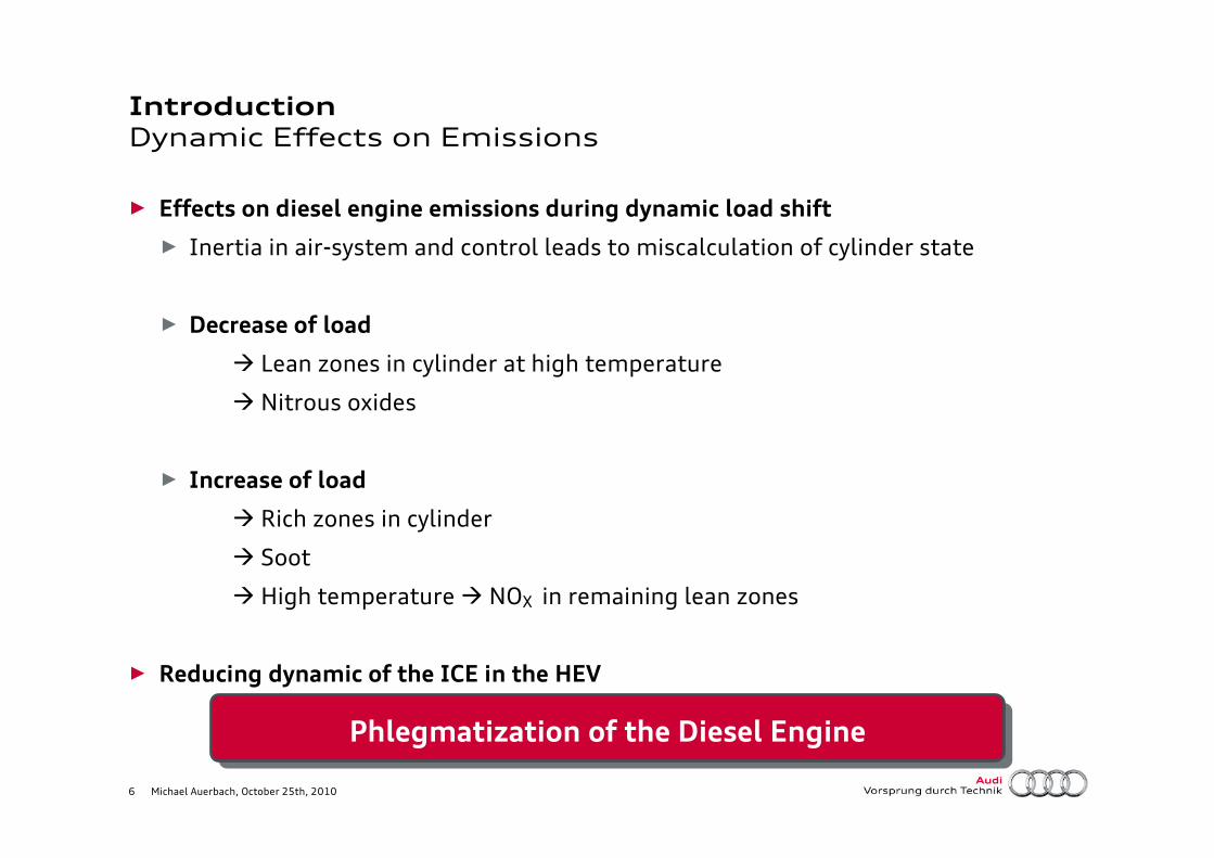
IntroductionDynamic Effects on Emissions
► Effects on diesel engine emissions during dynamic load shift
► Inertia in air-system and control leads to miscalculation of cylinder state
► Decrease of load
� Lean zones in cylinder at high temperature
� Nitrous oxides
► Increase of load
� Rich zones in cylinder
� Soot
� High temperature � NOX in remaining lean zones
► Reducing dynamic of the ICE in the HEV
Phlegmatization of the Diesel Engine
7 Michael Auerbach, October 25th, 2010
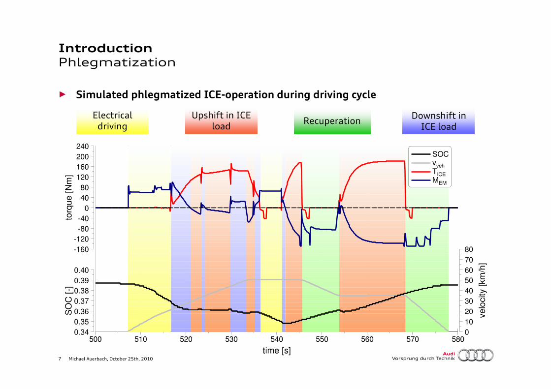
IntroductionPhlegmatization
► Simulated phlegmatized ICE-operation during driving cycle
Electrical driving
Upshift in ICE load
Recuperation Downshift in ICE load
time [s]
500 510 520 530 540 550 560 570 580
torq
ue [
Nm
]
-160
-120
-80
-40
0
40
80
120
160
200
240 SOC vveh
TICE
MEM
velo
city [
km
/h]
0
10
20
30
40
50
60
70
80
SO
C [
-]
0.34
0.35
0.36
0.37
0.38
0.39
0.40
8 Michael Auerbach, October 25th, 2010
IntroductionTransient Simulations
► Why transient Simulation?
► Mean-Value models are fast but hide numerous disadvantages
� Steady-state look up tables do not reflect realistic behavior of air path and
heat up, therefore conditions for combustion may be incorrect
► Leaves the possibility to simulate emissions
� Delays in the air path and the control can be modeled
► Allows simulation of engine and exhaust aftertreatment warm-up
� Interaction with combustion model (wall heat transfer) and friction model
�Models of aftertreatment system can be added
► Inevitable for the simulation of effects on phlegmatization

9 Michael Auerbach, October 25th, 2010
Thermal Model
Aftertreatment Model
Engine Model*
EGR VNG
Engine Model Overview
► Requirements for a transient diesel engine model
► Various (fast) sub-models and appropriate controls
► Model scheme
► Injection Model for transient simulations
Soft - ECU
Injection
* 1D-Simulation and Combustion
10 Michael Auerbach, October 25th, 2010
Engine ModelInjection
► Measurements for each operating point (OP)
► High experimental effort
► Limited ability to simulate transient load/speed shifts
► Good and fast results at discrete OP’s
► Physical incompressible flow model
► High modeling effort
► Lot of data needed (geometries, coefficients, fluid properties,…)
► High calculation effort though high access to physical processes
► Empirical model
► Reasonable experimental effort
► Experimental data adequate for parameterization
► Accurate results combined with acceptable computational effort

11 Michael Auerbach, October 25th, 2010
Engine ModelInjection
inje
ction r
ate
[m
g/s
]
-505
10152025303540
time [s]
-0.0005 0.0000 0.0005 0.0010 0.0015 0.0020 0.0025 0.0030 0.0035
inje
cto
r p
ote
ntia
l [V
]
-200
20406080
100120140160
Measurements Preprocessing Model Generating Integration
200 µs @ 1600 bar 500 µs @ 1600 bar 800 µs @ 1600 bar 1100 µs @ 1600 bar
► Fingerprint measurements
► Gradually incrementing injection duration at constant rail pressure level
► Repeating measurement for various rail pressure levels
[mgs]

12 Michael Auerbach, October 25th, 2010
inje
ctio
n r
ate
[m
g/m
s]
-5
0
5
10
15
20
25
30
35
40
time [s]
-0.0005 0.0000 0.0005 0.0010 0.0015 0.0020 0.0025 0.0030 0.0035
Engine ModelInjection
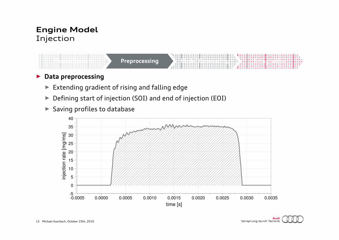
► Data preprocessing
► Extending gradient of rising and falling edge
► Defining start of injection (SOI) and end of injection (EOI)
Measurements Preprocessing Model Generating Integration
SOI EOI
13 Michael Auerbach, October 25th, 2010
Engine ModelInjection
► Data preprocessing
► Extending gradient of rising and falling edge
► Defining start of injection (SOI) and end of injection (EOI)
► Saving profiles to database
Measurements Preprocessing Model Generating Integrationin
jectio
n r
ate
[m
g/m
s]
-5
0
5
10
15
20
25
30
35
40
time [s]
-0.0005 0.0000 0.0005 0.0010 0.0015 0.0020 0.0025 0.0030 0.0035
14 Michael Auerbach, October 25th, 2010
rail
pre
ssure
[bar]
0
200
400
600
800
1000
1200
1400
1600
1800
2000
2200
injection activation duration [ms]
0 100 200 300 400 500 600 700 800 900 1000 1100
Engine ModelInjection
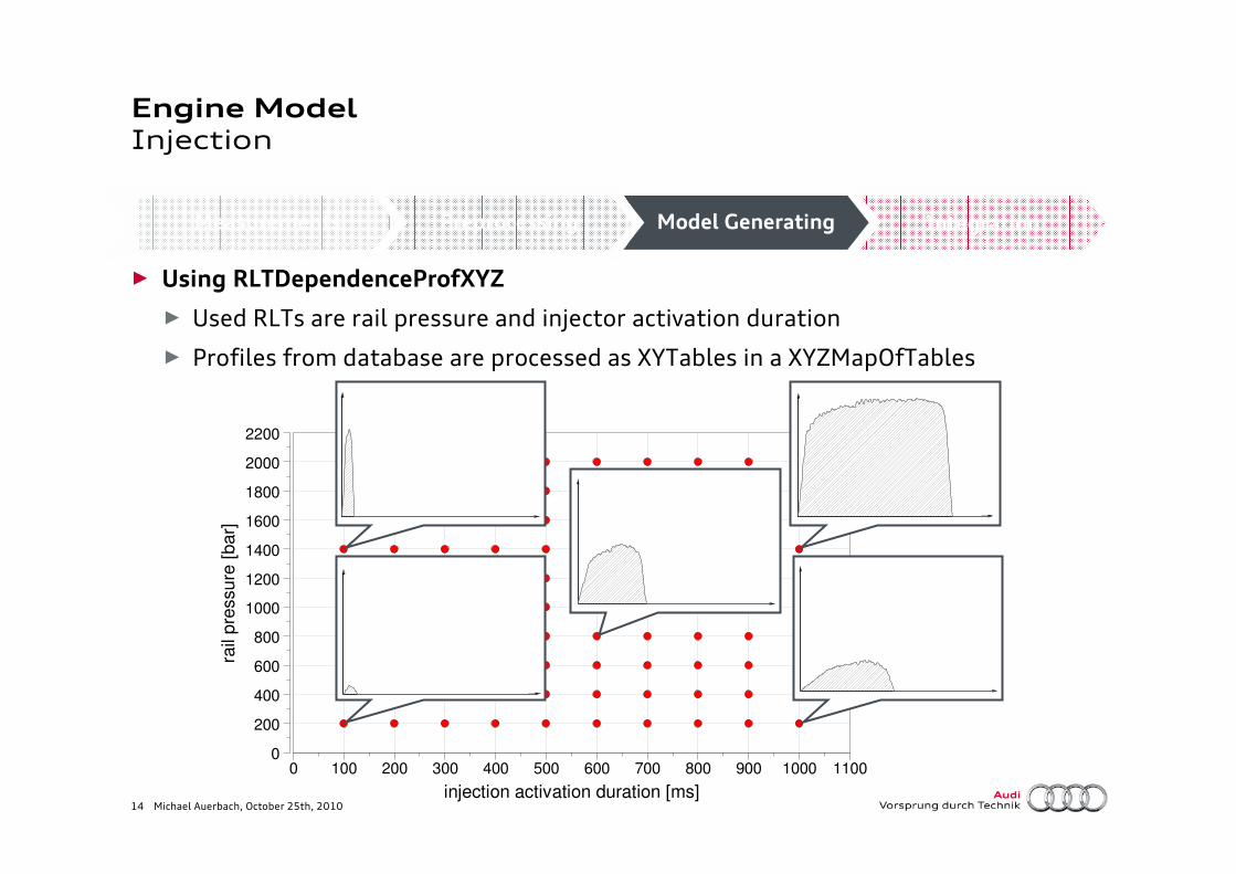
► Using RLTDependenceProfXYZ
► Used RLTs are rail pressure and injector activation duration
► Profiles from database are processed as XYTables in a XYZMapOfTables
Measurements Preprocessing Model Generating Integration

15 Michael Auerbach, October 25th, 2010
Engine ModelInjection
Measurements Preprocessing Model Generating Integration
InjMultiProfileConn
SOAAD
pRail
SOI
ID
∆pdrop
Soft - ECU
∆dmInj/dt
► Start of Injection
► Variable Profile Dependency Object
► RLTs (ID, pInj)
►Mass flow dropmInj
∆tInj
16 Michael Auerbach, October 25th, 2010
injectiondelay
Engine ModelInjection
Measurements Preprocessing Model Generating Integration
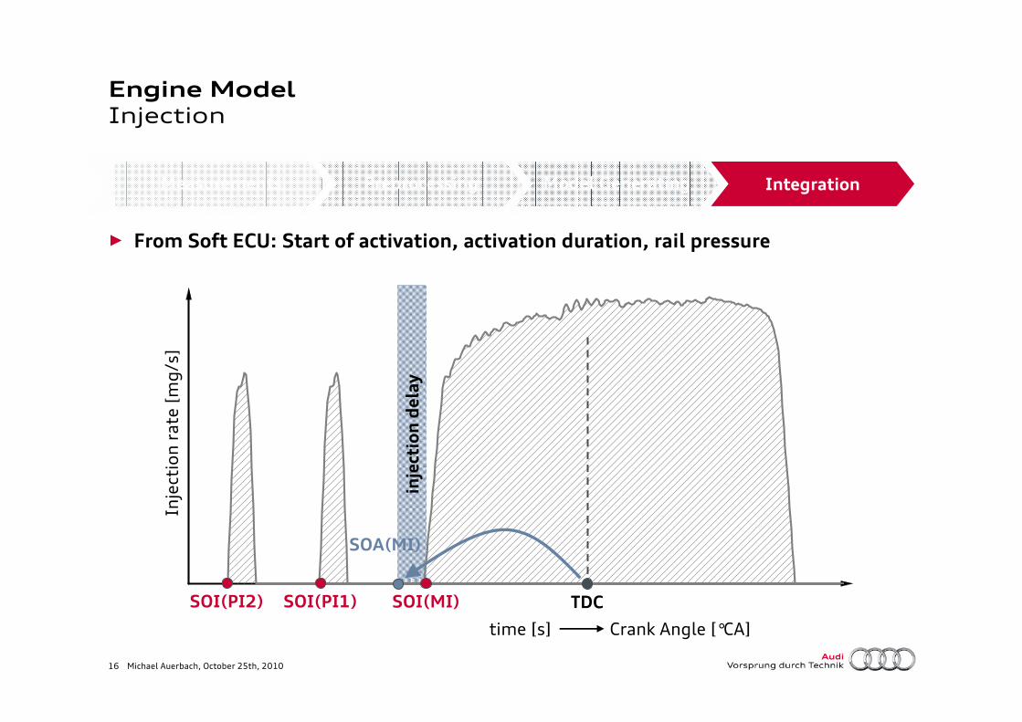
► From Soft ECU: Start of activation, activation duration, rail pressure
Injectionrate [mg/s]
time [s]
TDCSOI(MI)SOI(PI1)SOI(PI2)
SOA(MI)
Crank Angle [°CA]

17 Michael Auerbach, October 25th, 2010
inje
ction
ra
te [
mg
/°C
A]
0.0
0.5
1.0
1.5
2.0
2.5
3.0
3.5
crank angle [°CA]
-50 -30 -10 10 30
crank angle [°CA]
-50 -30 -10 10 30
time [s]0 5 10 15 20 25 30
IME
P [
bar]
0
4
8
12
16
20
24
28
inje
cte
d m
ass [
mg]
0
10
20
30
40
50
60
70
80
Transient SimulationResults
► Validation: Load shift @ 2000 rpm
► Time-scale results
� Engine model vs. Engine test bench
► Cuts at discrete time steps (°CA-based)
� Injector model vs. Injector test bench
measurement simulation

18 Michael Auerbach, October 25th, 2010
Summary & Outlook
► Diesel-HEV is important for future mobility
► Control-strategy must focus on emissions, fuel consumption and driveability
► Main effect on emissions is Phlegmatization
► Transient engine simulation is inevitable for surveys on this effect
► Fast injection model and control needed for transient simulations
► Approach to a phenomenological injection model was shown
► Outlook
► Coupling of further models (thermal, exhaust aftertreatment,…)
► Using model for pre-application and testing of Diesel-HEV-Strategy
19 Michael Auerbach, October 25th, 2010
Thank you for your attention!
Acknowledgements
Thanks for support and inspiration to
Michael Grill (FKFS),
Björn Lumpp (MAN) and
Torsten Rausch (AUDI AG)