Modelling of Seebeck effect in electron beam deep welding ... · Fabrizio Dughiero, Egbert Baake,...
17
„Im Rahmen der hochschulweiten Open-Access-Strategie für die Zweitveröffentlichung identifiziert durch die Universitätsbibliothek Ilmenau.“ “Within the academic Open Access Strategy identified for deposition by Ilmenau University Library.” „Dieser Beitrag ist mit Zustimmung des Rechteinhabers aufgrund einer (DFG-geförderten) Allianz- bzw. Nationallizenz frei zugänglich.“ „This publication is with permission of the rights owner freely accessible due to an Alliance licence and a national licence (funded by the DFG, German Research Foundation) respectively.” Ziolkowski, Marek; Brauer, Hartmut: Modelling of Seebeck effect in electron beam deep welding of dissimilar metals URN: urn:nbn:de:gbv:ilm1-2014210107 Published OpenAccess: September 2014 Original published in: Compel : international journal of computation & mathematics in electrical & electronic engineering. - Bradford : Emerald (ISSN-p 0332-1649). - 28 (2009) 1, S. 140-153. DOI: 10.1108/03321640910918940 URL: http://dx.doi.org/10.1108/03321640910918940 [Visited: 2014-09-02]
Transcript of Modelling of Seebeck effect in electron beam deep welding ... · Fabrizio Dughiero, Egbert Baake,...
„Im Rahmen der hochschulweiten Open-Access-Strategie für die Zweitveröffentlichung identifiziert durch die Universitätsbibliothek Ilmenau.“
“Within the academic Open Access Strategy identified for deposition by Ilmenau University Library.”
„Dieser Beitrag ist mit Zustimmung des Rechteinhabers aufgrund einer (DFG-geförderten) Allianz- bzw. Nationallizenz frei zugänglich.“
„This publication is with permission of the rights owner freely accessible due to an Alliance licence and a national licence (funded by the DFG, German Research Foundation) respectively.”
Ziolkowski, Marek; Brauer, Hartmut:
Modelling of Seebeck effect in electron beam deep welding of dissimilar metals
URN: urn:nbn:de:gbv:ilm1-2014210107
Published OpenAccess: September 2014
Original published in: Compel : international journal of computation & mathematics in electrical & electronic engineering. - Bradford : Emerald (ISSN-p 0332-1649). - 28 (2009) 1, S. 140-153. DOI: 10.1108/03321640910918940 URL: http://dx.doi.org/10.1108/03321640910918940 [Visited: 2014-09-02]
COMPEL - The international journal for computation and mathematicsin electrical and electronic engineeringModelling of Seebeck effect in electron beam deep welding of dissimilar metalsMarek Ziolkowski Hartmut Brauer
Article information:To cite this document:Marek Ziolkowski Hartmut Brauer, (2009),"Modelling of Seebeck effect in electron beam deep welding ofdissimilar metals", COMPEL - The international journal for computation and mathematics in electrical andelectronic engineering, Vol. 28 Iss 1 pp. 140 - 153Permanent link to this document:http://dx.doi.org/10.1108/03321640910918940
Downloaded on: 02 September 2014, At: 07:57 (PT)References: this document contains references to 6 other documents.To copy this document: [email protected] fulltext of this document has been downloaded 545 times since 2009*
Users who downloaded this article also downloaded:Ahmed Masmoudi, S. Laïssaoui, M.R. Mékidèche, D. Sedira, A. Ladjimi, (2007),"Dynamic modeling ofinduction motor taking into account thermal stresses", COMPEL - The international journal for computationand mathematics in electrical and electronic engineering, Vol. 26 Iss 1 pp. 36-47Fabrizio Dughiero, Egbert Baake, Michele Forzan, P. Di Barba, F. Dughiero, E. Sieni, (2011),"Synthesizinga nanoparticle distribution in magnetic fluid hyperthermia", COMPEL - The international journal forcomputation and mathematics in electrical and electronic engineering, Vol. 30 Iss 5 pp. 1507-1516Carlos F.R. Lemos Antunes, Carlos P. Cabrita, #tefan Nagy, Teodor Leuca, Claudiu Mich,(2010),"Numerical modeling of the coupled electromagnetic and thermal fields in the controlled solidificationprocess", COMPEL - The international journal for computation and mathematics in electrical and electronicengineering, Vol. 29 Iss 5 pp. 1266-1275
Access to this document was granted through an Emerald subscription provided by 514728 []
For AuthorsIf you would like to write for this, or any other Emerald publication, then please use our Emerald forAuthors service information about how to choose which publication to write for and submission guidelinesare available for all. Please visit www.emeraldinsight.com/authors for more information.
About Emerald www.emeraldinsight.comEmerald is a global publisher linking research and practice to the benefit of society. The companymanages a portfolio of more than 290 journals and over 2,350 books and book series volumes, as well asproviding an extensive range of online products and additional customer resources and services.
Emerald is both COUNTER 4 and TRANSFER compliant. The organization is a partner of the Committeeon Publication Ethics (COPE) and also works with Portico and the LOCKSS initiative for digital archivepreservation.
Dow
nloa
ded
by U
NIV
ERSI
TAET
SBIB
LIO
THEK
ILM
ENA
U A
t 07:
57 0
2 Se
ptem
ber 2
014
(PT)

*Related content and download information correct at time of download.
Dow
nloa
ded
by U
NIV
ERSI
TAET
SBIB
LIO
THEK
ILM
ENA
U A
t 07:
57 0
2 Se
ptem
ber 2
014
(PT)
Modelling of Seebeck effectin electron beam deep welding
of dissimilar metalsMarek Ziolkowski
Department of Electromagnetic Fields/ThEE,Technische Universitat Ilmenau, Ilmenau, Germany andTechnical University of Szczecin, Szczecin, Poland, and
Hartmut BrauerDepartment of Electromagnetic Fields/ThEE,
Technische Universitat Ilmenau, Ilmenau, Germany
Abstract
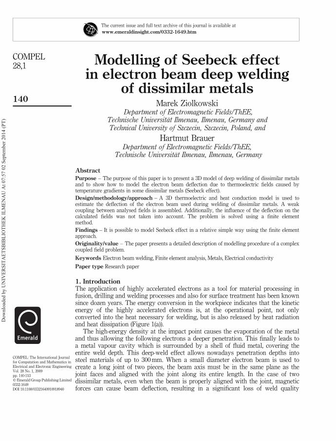
Purpose – The purpose of this paper is to present a 3D model of deep welding of dissimilar metalsand to show how to model the electron beam deflection due to thermoelectric fields caused bytemperature gradients in some dissimilar metals (Seebeck effect).
Design/methodology/approach – A 3D thermoelectric and heat conduction model is used toestimate the deflection of the electron beam used during welding of dissimilar metals. A weakcoupling between analysed fields is assembled. Additionally, the influence of the deflection on thecalculated fields was not taken into account. The problem is solved using a finite elementmethod.
Findings – It is possible to model Seebeck effect in a relative simple way using the finite elementapproach.
Originality/value – The paper presents a detailed description of modelling procedure of a complexcoupled field problem.
Keywords Electron beam welding, Finite element analysis, Metals, Electrical conductivity
Paper type Research paper
1. IntroductionThe application of highly accelerated electrons as a tool for material processing infusion, drilling and welding processes and also for surface treatment has been knownsince dozen years. The energy conversion in the workpiece indicates that the kineticenergy of the highly accelerated electrons is, at the operational point, not onlyconverted into the heat necessary for welding, but is also released by heat radiationand heat dissipation (Figure 1(a)).
The high-energy density at the impact point causes the evaporation of the metaland thus allowing the following electrons a deeper penetration. This finally leads toa metal vapour cavity which is surrounded by a shell of fluid metal, covering theentire weld depth. This deep-weld effect allows nowadays penetration depths intosteel materials of up to 300mm. When a small diameter electron beam is used tocreate a long joint of two pieces, the beam axis must be in the same plane as thejoint faces and aligned with the joint along its entire length. In the case of twodissimilar metals, even when the beam is properly aligned with the joint, magneticforces can cause beam deflection, resulting in a significant loss of weld quality
The current issue and full text archive of this journal is available at
www.emeraldinsight.com/0332-1649.htm
COMPEL28,1
140
COMPEL: The International Journalfor Computation and Mathematics inElectrical and Electronic EngineeringVol. 28 No. 1, 2009pp. 140-153q Emerald Group Publishing Limited0332-1649DOI 10.1108/03321640910918940
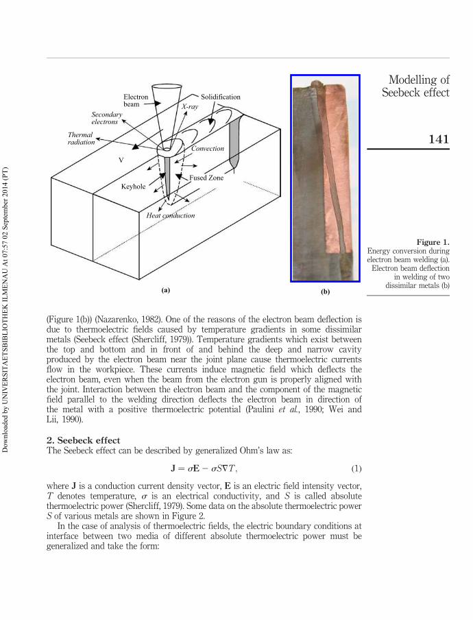
(Figure 1(b)) (Nazarenko, 1982). One of the reasons of the electron beam deflection isdue to thermoelectric fields caused by temperature gradients in some dissimilarmetals (Seebeck effect (Shercliff, 1979)). Temperature gradients which exist betweenthe top and bottom and in front of and behind the deep and narrow cavityproduced by the electron beam near the joint plane cause thermoelectric currentsflow in the workpiece. These currents induce magnetic field which deflects theelectron beam, even when the beam from the electron gun is properly aligned withthe joint. Interaction between the electron beam and the component of the magneticfield parallel to the welding direction deflects the electron beam in direction ofthe metal with a positive thermoelectric potential (Paulini et al., 1990; Wei andLii, 1990).
2. Seebeck effectThe Seebeck effect can be described by generalized Ohm’s law as:
J ¼ sE2 sS7T; ð1Þ
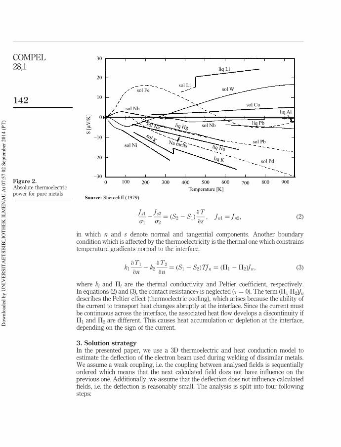
where J is a conduction current density vector, E is an electric field intensity vector,T denotes temperature, s is an electrical conductivity, and S is called absolutethermoelectric power (Shercliff, 1979). Some data on the absolute thermoelectric powerS of various metals are shown in Figure 2.
In the case of analysis of thermoelectric fields, the electric boundary conditions atinterface between two media of different absolute thermoelectric power must begeneralized and take the form:
Figure 1.Energy conversion duringelectron beam welding (a).
Electron beam deflectionin welding of two
dissimilar metals (b)
Electronbeam
(a) (b)
Thermalradiation
Secondaryelectrons
SolidificationX-ray
Convection
Heat conduction
Fused ZoneKeyhole
V
Modelling ofSeebeck effect
141
Dow
nloa
ded
by U
NIV
ERSI
TAET
SBIB
LIO
THEK
ILM
ENA
U A
t 07:
57 0
2 Se
ptem
ber 2
014
(PT)
J s1
s12
J s2
s2¼ ðS2 2 S1Þ
›T
›s; J n1 ¼ J n2; ð2Þ
in which n and s denote normal and tangential components. Another boundarycondition which is affected by the thermoelectricity is the thermal one which constrainstemperature gradients normal to the interface:
k1›T1
›n2 k2
›T2
›n¼ ðS1 2 S2ÞTJn ¼ ðP1 2P2ÞJ n; ð3Þ
where ki and Pi are the thermal conductivity and Peltier coefficient, respectively.In equations (2) and (3), the contact resistancet is neglected (t ¼ 0). The term (P1-P2)Jndescribes the Peltier effect (thermoelectric cooling), which arises because the ability ofthe current to transport heat changes abruptly at the interface. Since the current mustbe continuous across the interface, the associated heat flow develops a discontinuity ifP1 and P2 are different. This causes heat accumulation or depletion at the interface,depending on the sign of the current.
3. Solution strategyIn the presented paper, we use a 3D thermoelectric and heat conduction model toestimate the deflection of the electron beam used during welding of dissimilar metals.We assume a weak coupling, i.e. the coupling between analysed fields is sequentiallyordered which means that the next calculated field does not have influence on theprevious one. Additionally, we assume that the deflection does not influence calculatedfields, i.e. the deflection is reasonably small. The analysis is split into four followingsteps:
Figure 2.Absolute thermoelectricpower for pure metals
30
sol Fesol Li
sol W
sol Culiq Al
liq Pb
liq Li
sol Pb
sol Pd
sol Nb
liq Na
liq K
liq Hg
Na melts
sol Na
sol Nb
sol Ni
sol K
20
10
0
S [µ
V/K
]
–10
–20
–300 100 200 300 400 500
Temperature [K]Source: Sherceliff (1979)
600 700 800 900
COMPEL28,1
142
Dow
nloa
ded
by U
NIV
ERSI
TAET
SBIB
LIO
THEK
ILM
ENA
U A
t 07:
57 0
2 Se
ptem
ber 2
014
(PT)
(1) heat transfer (HT) problem, where the temperature field distribution iscalculated;
(2) conductive media problem, where the current density distribution evoked bySeebeck effect is estimated;
(3) magnetic problem, where the magnetic flux density distribution producedby current density distribution calculated in the previous step is calculated;and
(4) deflection estimation, where the trajectory of the electron beam affected bypreviously calculated magnetic field is found.
Problems 1-3 are solved using a finite element method (FEM). In that case,we have applied the program COMSOL v.3.3 which enables to solve coupledproblems using the same geometry model and can be easy coupled with Matlab.To solve problem 4, we wrote a small procedure in Matlab which simulates thedeflection of the electron beam using a magnetic flux density calculated in FEMprogram.
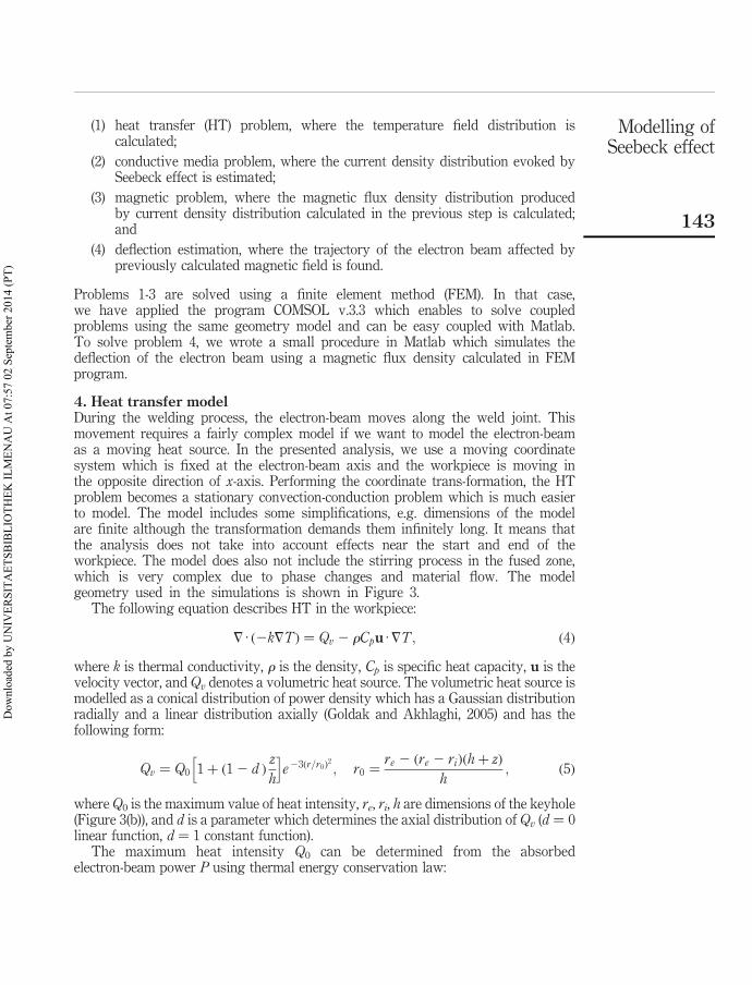
4. Heat transfer modelDuring the welding process, the electron-beam moves along the weld joint. Thismovement requires a fairly complex model if we want to model the electron-beamas a moving heat source. In the presented analysis, we use a moving coordinatesystem which is fixed at the electron-beam axis and the workpiece is moving inthe opposite direction of x-axis. Performing the coordinate trans-formation, the HTproblem becomes a stationary convection-conduction problem which is much easierto model. The model includes some simplifications, e.g. dimensions of the modelare finite although the transformation demands them infinitely long. It means thatthe analysis does not take into account effects near the start and end of theworkpiece. The model does also not include the stirring process in the fused zone,which is very complex due to phase changes and material flow. The modelgeometry used in the simulations is shown in Figure 3.
The following equation describes HT in the workpiece:
7 · ð2k7TÞ ¼ Qv 2 rCpu ·7T; ð4Þ
where k is thermal conductivity, r is the density, Cp is specific heat capacity, u is thevelocity vector, and Qv denotes a volumetric heat source. The volumetric heat source ismodelled as a conical distribution of power density which has a Gaussian distributionradially and a linear distribution axially (Goldak and Akhlaghi, 2005) and has thefollowing form:
Qv ¼ Q0 1 þ ð1 2 d Þz
h
h ie23ðr=r0Þ
2
; r0 ¼re 2 ðre 2 riÞðhþ zÞ
h; ð5Þ
where Q0 is the maximum value of heat intensity, re, ri, h are dimensions of the keyhole(Figure 3(b)), and d is a parameter which determines the axial distribution of Qv (d ¼ 0linear function, d ¼ 1 constant function).
The maximum heat intensity Q0 can be determined from the absorbedelectron-beam power P using thermal energy conservation law:
Modelling ofSeebeck effect
143
Dow
nloa
ded
by U
NIV
ERSI
TAET
SBIB
LIO
THEK
ILM
ENA
U A
t 07:
57 0
2 Se
ptem
ber 2
014
(PT)
P ¼
V
ZQvdV ¼
Z 0
2h
Z 2p
0
Z r0
0
Qvðr; zÞrdrdwdz: ð6Þ
The final expression of Q0 takes the form:
Q0 ¼36P
pð1 2 e23Þh
1
4ðr2e þ reri þ r2
i Þ2 ð1 2 d Þð3r2e þ 2reri þ r2
i Þ: ð7Þ
Assuming re ¼ ri ¼ r0 and 1 2 e23 ø 1; we can write equation (5) in the followingform:
Qvðr; zÞ ¼6P
pr20h
1 þ ð1 2 d Þz=h
1 þ de23ðr=r0Þ
2
: ð8Þ
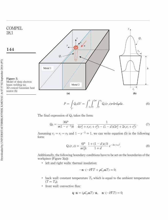
Additionally, the following boundary conditions have to be set on the boundaries of theworkpiece (Figure 3(a)):
. left and right walls: thermal insulation:
2n · ð2k7T þ rCpuTÞ ¼ 0;
. back wall: constant temperature T0 which is equal to the ambient temperature(T ¼ T0);
. front wall: convective flux:
q ·n ¼ ðrCpuTÞ ·n; n · ð2k7TÞ ¼ 0;
Figure 3.Model of deep electronbeam welding (a).3D conical Gaussian heatsource (b)
y
Qv
Qv
z
z
xu
Metal 1
Metal 2
(a) (b)
ri
re
h
COMPEL28,1
144
Dow
nloa
ded
by U
NIV
ERSI
TAET
SBIB
LIO
THEK
ILM
ENA
U A
t 07:
57 0
2 Se
ptem
ber 2
014
(PT)
. downside and upside walls: they lose heat due to natural convection andsurface-to-ambient radiation. The corresponding heat flux expressions are:
2n · ð2k7T þ rCpuTÞ ¼ hðT0 2 TÞ þ 1sSB T40 2 T 4
� �;
where 1 is hemispherical emissitivity, sSB is Stefan-Boltzman constant, and h is HTcoefficient for natural convection.
5. Conductive media model (DC)Using identity 7 · J ¼ 0 and electric potential definition E ¼ 27V ; we transformequation (1) to the following equation:
7 · ½sðTÞ7V � ¼ 7 · Je; Je ¼ 2sðTÞS7T; ð9Þ
where T is temperature calculated in HT problem. Equation (9) should be solved inregions Metals 1 and 2 (Figure 3). Current density Je is only defined in elements wheretemperature T is less than melting temperature (Tmelt).
On the downside wall, we set potential V ¼ 0 and on all the others, we force anelectric insulation boundary condition ð7 · J ¼ 0Þ: At the interface between metals onlystandard continuity condition n · ðJ 1 2 J 2Þ ¼ 0 is implemented.
6. Magnetic modelfMagnetic flux density B is calculated with the help of magnetic vector potential Adefined as: B ¼ 7 £A; together with Coulomb’s gauge 7 ·A ¼ 0 to assure uniquenessof potential A. Using above and Maxwell equation 7 £H ¼ J; we receive the followingequation:
7 £1
m7 £A
� �¼ J; ð10Þ
where J is the current density distribution calculated in DC problem and m is amagnetic permeability of media. In magnetic model (MA) problem, the geometry of themodel has to be changed by adding additional ambient regions above and below theworkpiece (Figure 3) to enable setting proper boundary conditions for magnetic vectorpotential A. On all side walls, the electric insulation boundary condition ðn £H5 0Þ isset whereas, on other walls, the magnetic insulation boundary condition n £A ¼ 0 ischosen. Magnetic permeability m for both metals is set to mo because even if we haveferromagnetic materials, in most parts of regions where currents evoked by Seebeckeffect are flowing, temperature is greater than the Curie temperature (TCurie) abovewhich ferromagnetic materials loose their magnetic features.
7. Deflection modelThe electron beam trajectory is deflected by Lorentz force according to theequation:
mdv
dt¼ 2ev £ B; ð11Þ
Modelling ofSeebeck effect
145
Dow
nloa
ded
by U
NIV
ERSI
TAET
SBIB
LIO
THEK
ILM
ENA
U A
t 07:
57 0
2 Se
ptem
ber 2
014
(PT)
where m is electron mass (kg), e is electron charge (C), and v is the velocity ofelectrons in the electron beam. Because the Lorentz force is perpendicular to thelocal velocity vector, the magnitude of v remains constant and could be easycalculated from energy conservation law as:
v0 ¼
ffiffiffiffiffiffiffiffiffi2eU
m
r; ð12Þ
where U is accelerating voltage. Displacement r of the electron can be calculatedin an iterative way using following sequence of formulas:
Dv ¼ 2e
mv £ BDt ! vi ¼ vi21 þ Dv; Dr i ¼ viDt! r i ¼ r i21 þ Dri ð13Þ
where Dt is a small enough time step determined by the user. The deflection ofthe electron beam is calculated until the depth of the keyhole is reached.
8. Simulations8.1 Material dataAs Metals 1 and 2, pure iron and copper are chosen, respectively. The thermalconductivity k and the specific heat capacity Cp are defined as temperature dependentfunctions according (Lide, 2006) (Figure 4).
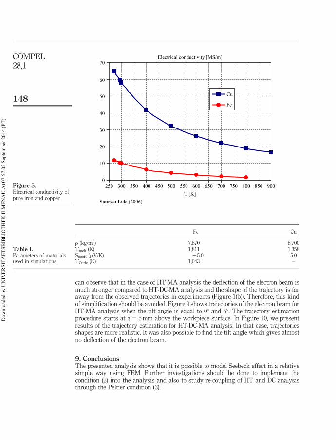
The electrical conductivity is also taken into account as a temperature dependentfunction (Lide, 2006) (Figure 5).
Other material parameters are presented in Table I.
8.2 ResultsIn all simulations, following parameters have been chosen: vector of welding speedu ¼ 22:5ex mm=s;absorbed electron beam power P ¼ 30 kW, radius of the keyholer0 ¼ 0.3 mm, depth of the keyhole h ¼ 70 mm.
Figure 6 shows temperature distribution at various cross-section planes(HT analysis).
To model Seebeck effect, we have applied two approaches:
(1) simplified HT-MA analysis, where J in equation (10) is defined directly as Je inequation (9); and
(2) full HT-DC-MA analysis.
In the first approach, the continuity conditions at the interface between metals are notfulfilled. Figure 7 shows current density distributions for both approaches. Figure 8shows magnetic flux density in the vicinity of fusion zone for MA and DC-MAanalysis.
After calculations of magnetic flux density distributions, the trajectory of theelectron beam has been estimated according to equation (13). We have also implementedthe possibility of tilting the electron beam against the workpiece z-axis whichenables us, in a simple way, to test the influence of the tilt angle on the trajectorybehaviour.
However, both approaches calculate deflection in the proper direction (the electronbeam is deflected towards material with the greater absolute thermoelectric power), we
COMPEL28,1
146
Dow
nloa
ded
by U
NIV
ERSI
TAET
SBIB
LIO
THEK
ILM
ENA
U A
t 07:
57 0
2 Se
ptem
ber 2
014
(PT)
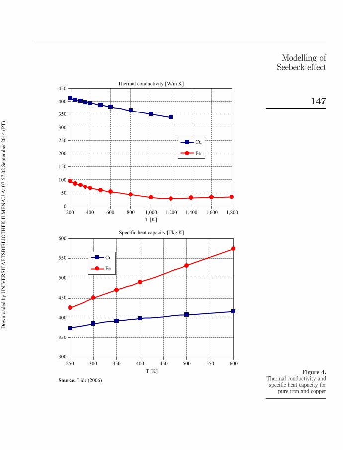
Figure 4.Thermal conductivity and
specific heat capacity forpure iron and copper
Thermal conductivity [W/m K]
0
50
100
150
200
250
300
350
400
450
200 400 600 800 1,000 1,200 1,400 1,600 1,800T [K]
Cu
Fe
Specific heat capacity [J/kg K]
300
350
400
450
500
550
600
250 300 350 400 450 500 550 600T [K]
Cu
Fe
Source: Lide (2006)
Modelling ofSeebeck effect
147
Dow
nloa
ded
by U
NIV
ERSI
TAET
SBIB
LIO
THEK
ILM
ENA
U A
t 07:
57 0
2 Se
ptem
ber 2
014
(PT)
can observe that in the case of HT-MA analysis the deflection of the electron beam ismuch stronger compared to HT-DC-MA analysis and the shape of the trajectory is faraway from the observed trajectories in experiments (Figure 1(b)). Therefore, this kindof simplification should be avoided. Figure 9 shows trajectories of the electron beam forHT-MA analysis when the tilt angle is equal to 08 and 58. The trajectory estimationprocedure starts at z ¼ 5 mm above the workpiece surface. In Figure 10, we presentresults of the trajectory estimation for HT-DC-MA analysis. In that case, trajectoriesshapes are more realistic. It was also possible to find the tilt angle which gives almostno deflection of the electron beam.
9. ConclusionsThe presented analysis shows that it is possible to model Seebeck effect in a relativesimple way using FEM. Further investigations should be done to implement thecondition (2) into the analysis and also to study re-coupling of HT and DC analysisthrough the Peltier condition (3).
Figure 5.Electrical conductivity ofpure iron and copper
Electrical conductivity [MS/m]
0
10
20
30
40
50
60
70
250 300 350 400 450 500 550 600 650 700 750 800 850 900T [K]
Cu
Fe
Source: Lide (2006)
Fe Cu
r (kg/m3) 7,870 8,700Tmelt (K) 1,811 1,358S800K (mV/K) 25.0 5.0TCurie (K) 1,043 –
Table I.Parameters of materialsused in simulations
COMPEL28,1
148
Dow
nloa
ded
by U
NIV
ERSI
TAET
SBIB
LIO
THEK
ILM
ENA
U A
t 07:
57 0
2 Se
ptem
ber 2
014
(PT)
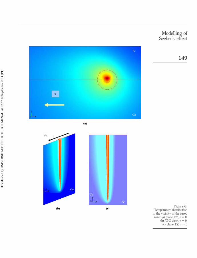
Figure 6.Temperature distribution
in the vicinity of the fusedzone: (a) plane XY, z ¼ 0;
(b) XYZ view, y ¼ 0;(c) plane YZ, x ¼ 0
u
Fe
Cuy
xz
(a)
uFe
Cu
Fe
Cu
yxz
y xz
(b) (c)
Modelling ofSeebeck effect
149
Dow
nloa
ded
by U
NIV
ERSI
TAET
SBIB
LIO
THEK
ILM
ENA
U A
t 07:
57 0
2 Se
ptem
ber 2
014
(PT)
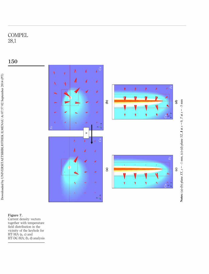
Figure 7.Current density vectorstogether with temperaturefield distribution in thevicinity of the keyhole forHT-MA (a, c) andHT-DC-MA; (b, d) analysis
u
(a)
(b)
(d)
(c)
Cu
Cu
Fe
FeFe
Cu
Cu
yx
z
yxz
yxz
yx
z
Not
es: (
a)-(
b) p
lane
XY,
z =
–1 m
m, (
c)-(
d) p
lane
YZ,
J a
t x =
0, T
at x
= –
5 m
m
COMPEL28,1
150
Dow
nloa
ded
by U
NIV
ERSI
TAET
SBIB
LIO
THEK
ILM
ENA
U A
t 07:
57 0
2 Se
ptem
ber 2
014
(PT)
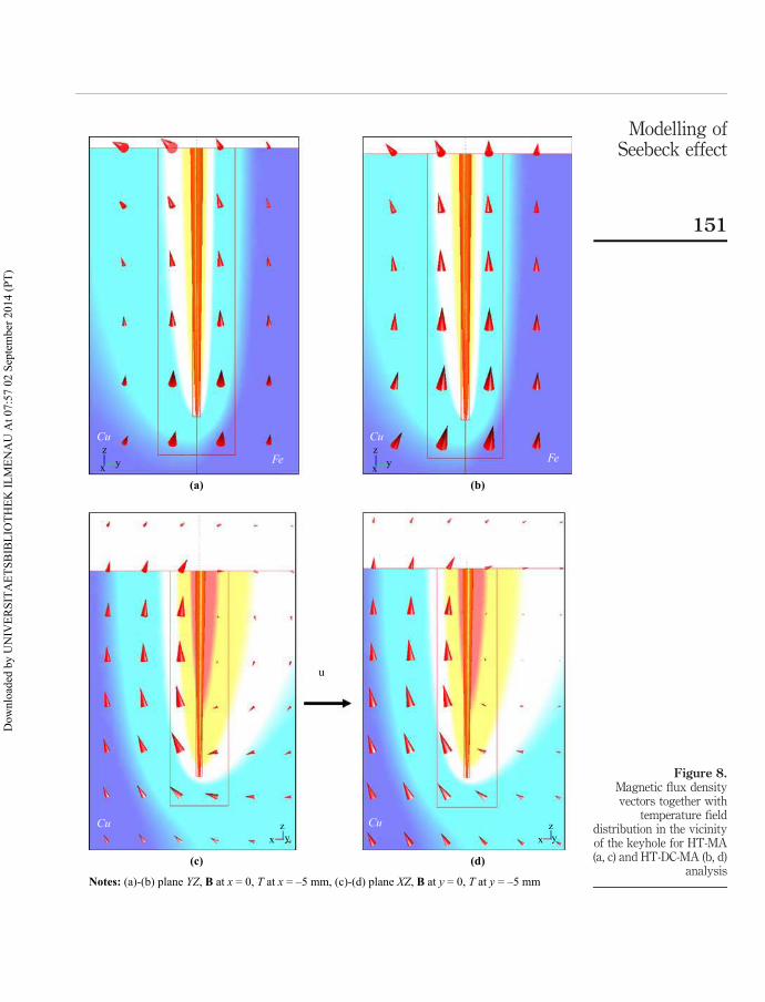
Figure 8.Magnetic flux densityvectors together with
temperature fielddistribution in the vicinityof the keyhole for HT-MA(a, c) and HT-DC-MA (b, d)
analysis
Fe
CuCu
Cu Cu
Fe
u
z
x yz
x y
zx y
zx y
(a) (b)
(c) (d)
Notes: (a)-(b) plane YZ, B at x = 0, T at x = –5 mm, (c)-(d) plane XZ, B at y = 0, T at y = –5 mm
Modelling ofSeebeck effect
151
Dow
nloa
ded
by U
NIV
ERSI
TAET
SBIB
LIO
THEK
ILM
ENA
U A
t 07:
57 0
2 Se
ptem
ber 2
014
(PT)
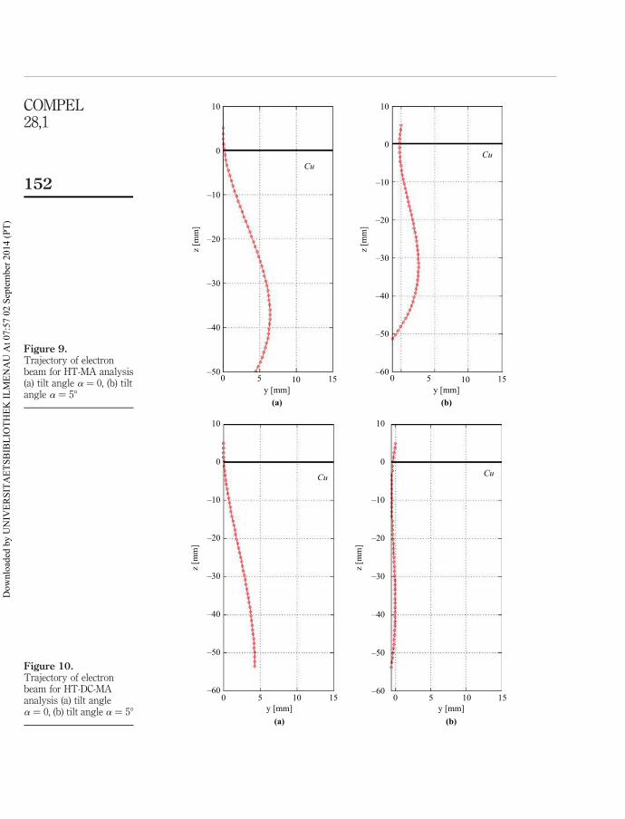
Figure 9.Trajectory of electronbeam for HT-MA analysis(a) tilt angle a ¼ 0, (b) tiltangle a ¼ 58
10
0
CuCu
–10
–20
z [m
m]
–30
–40
–50
10
0
–10
–20
z [m
m]
–30
–40
–50
–600 5 10
y [mm](a) (b)
15 0 5 10y [mm]
15
Figure 10.Trajectory of electronbeam for HT-DC-MAanalysis (a) tilt anglea ¼ 0, (b) tilt angle a ¼ 58
10
0
Cu Cu
–10
–20
z [m
m]
–30
–40
–60
–50
10
0
–10
–20
z [m
m]
–30
–40
–50
–600 5 10
y [mm](a) (b)
15 0 5 10y [mm]
15
COMPEL28,1
152
Dow
nloa
ded
by U
NIV
ERSI
TAET
SBIB
LIO
THEK
ILM
ENA
U A
t 07:
57 0
2 Se
ptem
ber 2
014
(PT)
References
Goldak, J.A. and Akhlaghi, M. (2005), Computational Welding Mechanics, SpringerScience þ Business Inc., Heidelberg.
Lide, D.R. (2006), CRC Handbook of Chemistry and Physics, 2006-2007, 87th ed.,Taylor&Francis, London.
Nazarenko, O.K. (1982), “Deflection of the electron beam in electron-beam welding”, Avt. Svarka,Vol. 346 No. 1, pp. 33-9.
Paulini, J., Simon, G. and Decker, I. (1990), “Beam deflection in electron beam welding bythermoelectric eddy currents”, J. Phys. D: Appl. Phys., Vol. 23, pp. 486-95.
Shercliff, J.A. (1979), “Thermoelectric magnetohydrodynamics”, J. FluidMech., Vol. 91, pp. 231-51.
Wei, P.S. and Lii, T.W. (1990), “Electron beam deflection when welding dissimilar metals”,Journal of Heat Transfer, Vol. 112, pp. 714-20.
About the authorsMarek Ziolkowski received MSc and PhD in electrical engineering from the Technical Universityof Szczecin in 1978 and 1984. Since 1978 he has been working there at the Chair of TheoreticalElectrotechnics and Computer Science. Since 2001 he is also with the Technische UniversitaetIlmenau. His main research interests include numerical calculations and visualization of EMfields, biomagnetic problems and inverse problems in magnetic fluid dynamics.Marek Ziolkowski is the corresponding author and can be contacted at: [email protected]
Hartmut Brauer received Diploma Engineer and Dr -Ing. in electrical engineering from theIlmenau Institute of Technology in 1975 and 1982. Since 1975 he is with the Department ofElectromagnetic Fields/Theoretical Electrical Engineering at the Technische UniversitaetIlmenau. His main research interests include computation of electromagnetic fields and inversefield problems/optimization in electrical engineering, with applications to bioelectromagnetics,magnetic fluid dynamics and educational aspects.
Modelling ofSeebeck effect
153
To purchase reprints of this article please e-mail: [email protected] visit our web site for further details: www.emeraldinsight.com/reprints
Dow
nloa
ded
by U
NIV
ERSI
TAET
SBIB
LIO
THEK
ILM
ENA
U A
t 07:
57 0
2 Se
ptem
ber 2
014
(PT)