MODUL / MODULE R 726MODUL / MODULE R 726 - Leroy-Somer · R 438 LS, R 448, R 449 (AREP, SHUNT/RBS)...
24
MODUL / MODULE R 726 MODUL / MODULE R 726 Netzparallelbetrieb Netzparallelbetrieb Paralleling with mains Paralleling with mains Anschluß und Einstellungen / Connection and adjustments Anschluß und Einstellungen / Connection and adjustments 2440 de/en - 10.2007 / d Spannungsversorgung Supply (U=U) C1 C2 UR UA (S1) + - [ = - ] UR UA (Cos ) Cos P1 (U=U) P2 ND MEM ON OFF (S2) (S1x S2) REGLER A.V.R. Spannung / Voltage (Rhe 470 Ω) AUSGANG OUTPUT ϕ ϕ ϕ ∑
Transcript of MODUL / MODULE R 726MODUL / MODULE R 726 - Leroy-Somer · R 438 LS, R 448, R 449 (AREP, SHUNT/RBS)...

MODUL / MODULE R 726MODUL / MODULE R 726 Netzparallelbetrieb Netzparallelbetrieb
Paralleling with mainsParalleling with mainsAnschluß und Einstellungen / Connection and adjustmentsAnschluß und Einstellungen / Connection and adjustments
2440 de/en - 10.2007 / d
SpannungsversorgungSupply
(U=U)
C1
C2
UR
UA
(S1)
+
-
[ = - ] UR UA
(Cos )
Cos
P1 (U=U)
P2ND MEMON
OFF
(S2)
(S1x S2)
REGLERA.V.R.
Spannung / Voltage(Rhe 470 Ω)
AUSGANGOUTPUT
ϕ
ϕ
ϕ
∑

2
Module R 726Modul R 726
ACHTUNG
Obwohl das Modul R726, das das Modul R725 ersetzt,genauso aussieht wie jenes,
wird es anders angeschlossen.Weiterhin können für den Anschluß dieses Moduls
Anpassungstransformatoren notwendig sein.
Siehe Handbuch:Ersetzen eines Moduls R725 durch ein Modul R726
CAUTION
Whether looking alike the module R725,the module R726 is differently connected
and may require for its connectionadditionnal adapting transformers.
See leaflet :Replacing module R725 by model R726
Ersetzen von Modulen mit 2 oder 3 Funktionen durch ein Modul R 726:
Replacement by a module R 726 of the following 2 and 3 functions modules :
Mechanisch austauschbar R 725 - 3 Funktionen / functions (cos ϕ; U = U)
R 725/100 - 3 Funktionen / functions (cos ϕ; U = U)
Mechanically interchangeable R 724 - 2 Funktionen / functions (cos ϕ)
Austauschbar, mit entsprechender RS 180 - 2 Funktionen / functions (cos ϕ)
Änderung der Verkabelung
Folgende Spannungsregler und Erregersysteme sind mit dem Modul R 726 kompatibel:
AVR's and excitation systems being conformable to module R 726 :
Spannungsregler / AVRs Erregersysteme / Excitation system
R 438 LS, R 448, R 449 (AREP, SHUNT/RBS)
R 129 (ACTR)
R 128.A, R 128.0, R 130 (ACTR/RBC)

INHALTSVERZEICHNIS
1 - ALLGEMEINES ...............................................4 1.1 - Anwendung 1.2 - Funktionsprinzip
2 - AUSSEHEN, ABMESSUNGEN .......................5
3 - BESCHREIBUNG ............................................53.1 - Regelbereich der ext. Potentiometer3.2 - Vorsichtsmaßnahmen bei der Verkabelung
4 - ANSCHLUSSPLAN .........................................7
5 - FUNKTION .......................................................8
6 - EINSTELLUNGEN ...........................................86.1 - Betriebsbereiche und Bedingungen
6.2 - Verfahren zur Einstellung bei der Inbe- triebnahme
7 - SPEZIFISCHE SCHUTZVORRICHTUNGEN 11
8 - PARALLELBETRIEB MIT EINEM ANDEREN GENERATOR (GETRENNT VOM NETZ) ......11
9 - NETZPARALLELBETRIEB ...........................11
10 - COSINUS-Ø-REGELUNG EINER ANLAGE ......................................................11
11 - BEHEBUNG VON STÖRUNGEN ................13 11.1 - Überprüfung des Reglers 11.2 - Überprüfung des Moduls R 726
12 - STATISCHE EINSTELLUNGEN .................13
13 - NULLUNGSART ..........................................16
14 - SPANNUNGEN AUSSERHALB DER STANDARDBEREICHE ...............................16
15 - ZUBEHÖR ...................................................17
16 - TECHNISCHE UNTERSTÜTZUNG / ERSATZTEILE .............................................17
17 - PRINZIPSCHALTBILDER ...........................1817.1 - Regler: R 438 LS oder R 448 oder
R 449 + R 72617.2 - Regler: R 129 + R 72617.3 - Regler: R 130 oder R 128-0 oder R 128-A
+ R726
18 - AUSSCHLIESSLICHE VERWENDUNG DER 2. FUNKTION ...............................................21
ACHTUNG :
1) WENN DER GENERATOR STILLSTEHT,KANN DIE NETZSPANNUNG AN DEN KLEM-MEN DER SPANNUNGSMESSUNG DES MO-DULS ANLIEGEN. LEBENSGEFAHR !
2) KEINE DIELEKTRISCHEN TESTS DURCH-FÜHREN, OHNE DAS MODUL UND DEN DAZU-GEHÖRIGEN REGLER ABZUKLEMMEN. GE-FAHR DER ZERSTÖRUNG DIESER MODULE.
INDEX
1 - GENERAL ........................................................4 1.1 - Purpose 1.2 - Operating principle 2 - OUTLINE DRAWING .......................................5
3 - DESCRIPTION .................................................53.1 - Adjustment range of remote pot.3.2 - Wiring precautions
4 - CONNECTION DIAGRAM ...............................7
5 - OPERATION PRINCIPLE ................................8
6 - ADJUSTMENTS ..............................................86.1 - Operating ranges and conditions 6.2 - Adjustment procedure commissionning
7 - SPECIFIC PROTECTIONS ............................11
8 - PARALLELING WITH ANOTHER GENE- RATOR (SEPARATE FROM MAINS) ................11
9 - SYNCHRONISING WITH MAINS WHEN PARALLELING WITH OTHER(S) GENERATOR(S) ...........................................11
10 - POWER FACTOR MONITORING OF A PLANT ................................................11
11 - TROUBLE SHOOTING ................................13 11.1 - Checking A.V.R. 11.2 - Checking module R 726
12 - STATIC ADJUSTMENTS ............................13
13 - NEUTRAL POINT STATUS .........................16
14 - VOLTAGE OUT OF STANDARD RANGES..16
15 - ACCESSORIES ...........................................17
16 - TECHNICAL ASSISTANCE ........................17
17 - PRINCIPLE CONNECTION DIAGRAMS ....1817.1 - A.V.R. : R 438 LS or R 448 or
R 449 + R 72617.2 - A.V.R. : R 129 + R 72617.3 - A.V.R. : R 130 or R 128-0 or R 128-A
+ R726 18 - USING ONLY THE 2nd FUNCTION ...........21
CAUTION :
1) WHEN THE GENERATOR, THE L.L. VOL-TAGE OF MAINS MAY BE ON THE VOLTAGESENSING TERMINALS OF THE MODULE. LIFE HAZARD.
2) DO NOT PROCEED TO HIGH VOLTAGETESTS WITHOUT DISCONNECTING (INSULA-TING) THE MODULE AND ASSOCIATED AVR.RISK OF DAMAGING COMPONENTS.
3
Module R 726Modul R 726

1 - ALLGEMEINES
1.1 - AnwendungMit dem Zusatzmodul R 726 können die nachfolgend auf-geführten Spannungsregler, deren 1. und wichtigsteFUNKTION die SPANNUNGSREGELUNG ist, in soge-nannte Regelsysteme mit "4 FUNKTIONEN" umgebautwerden. . die 2. FUNKTION ist dabei die COS ϕ − Regelung (Lei-stungsfaktor) unter Verwendung eines Stromwandlers, umeinen Netzparallelbetrieb zu realisieren, . die 3. FUNKTION ist dabei die Spannungsangleichungvor dem Zuschalten (U = U), die im allgemeinen von einemSynchronisationsschalter übernommen wird, der das Po-tentiometer der Spannungsregelung des Reglers steuert. . die 4. FUNKTION (verknüpft mit der 3. Funktion) ist derParallelbetrieb mit einem bzw. mehreren anderen Gene-ratoren, die mit demselben Modul R726 ausgestattet sind.Die Parallelschaltung findet während der Phase der Span-nungsangleichung vor dem Zuschalten zum Netz statt.
KOMPATIBLER ERREGUNGSSYSTEMREGLER
R 129 / R 128A Kompound . ACTR
R 128-0 / R 130 Kompound . RBC und ACTR
R 438 LS AREP oder ARPI
R 448 AREP oder ARPI oder ATR
Das Modul muß in der Nähe des Spannungsreglers instal-liert werden (innerhalb oder außerhalb des Generators). Eswird anstelle des externen Spannungspotentiometers zurSpannungseinstellung mit dem Regler verbunden.Das Potentiometer zur externen Spannungseinstel-lung wird bei Bedarf an das Modul R 726 angeschlossen.
DIE WEITEREN FUNKTIONEN DES SPANNUNGSREG-LERS (UNTERDREHZAHLSCHUTZ, BEGRENZUNG,ÜBERERREGUNG, …) WERDEN BEIBEHALTEN.
1.2 - Funktionsprinzip Blockschaltbild
1 - GENERAL
1.1 - PurposeThe additionnal Module R 726 enables to operate the follow-ing automatic voltage regulators (the 1ST FUNCTIONbeing VOLTAGE REGULATION) into a so said "4 FUNCTIONS" regulation system : . the 2nd FUNCTION being the POWER FACTOR("COS ϕ ") REGULATION, using an additionnal C.T., whenthe alternator is paralleling with the mains, . the 3rd FUNCTION being the BALANCE (EQUALIZA-TION) OF VOLTAGES before paralleling (U = U) which isgenerally realised by a synchronizer controlling the remotevoltage trimmer of the automatic voltage regulator, . the 4th FUNCTION (working with the 3rd) is parallel ope-ration with other(s) alternator(s) equipped with the samemodule R726 during voltage equalization before pa-ralleling with the mains.
VOLTAGE EXCITATIONREGULATOR SYSTEM
R 129 / R 128A compound . ACTR
R 128-0 / R 130 compound . RBC and ACTR R 438 LS AREP or ARPI
R 448 AREP or ARPI or ATR
The module must be installed close to the voltage regulator(inside or outside of the machine).It is connected to the voltage regulator in lieu of the remotevoltage potentiometer of the AVR.This remote voltage trimmer may be then connected if ne-cessary to the Module R 726.
THE OTHER FUNCTIONS OF VOLTAGE REGULATOR(UNDERSPEED PROTECTION, EXCITATION LIMIT,OVERCURRENT...) ARE KEPT.
1.2 - Operating principle Block diagram
4
Module R 726Modul R 726
(L2,L3)
(L2,L3)
NETZMAINS
NetzspannungMain voltage
UR
SpannungsversorgungSupply
(U=U)
C1
C2
UR
UA
UA
(L2,L3)C2
EXTERNE KONTAKTEREMOTE CONTACTSRC1
P1
RC2
ANZEIGE UND RELAISSCHALTUNGSTATUS SIGNALLING AND RELAYING
(S1)
+
+
+
-
[ = - ] UR UA
(Cos )(Cos )
STABP3
Cos
(U=U)
P2AND
[ = - ]
MEMON
OFF
(S2)
(S1x S2)
IA
(L1)
GErregerfeldExc field
Spannung / Voltage(Rhe 470 Ω)
AUSGANGOUTPUT
(UR)
PhasenstromLine current
(1A)
(VA)
Stromwandler /C.T.
Generatorspannung Generator output voltage
GENERATOR
(V =U)
ϕ
ϕ ϕ
ϕϕ
ϕ
∑
∑
∑
P4 Limit
100V
4.Funktion
HS / HV
TP/VT
NS / LV
REGLERA.V.R.
R 726 - 4 Funktionen

2 - AUSSEHEN / ABMESSUNGEN
3 - BESCHREIBUNG (siehe Zeichnung)Das Modul R726 besitzt 2 Klemmenleisten mit je 10 Klem-men (FASTON 6, 35 mm) J1 und J2. Von vorn gesehenwerden sie von links nach rechts mit den Ziffern 1-10 be-zeichnet.KLEMMENLEISTE J1: . Klemmen 1-2 : AUSGANG / STEUERUNG Anschluß anden Spannungsregler anstelle des externen Potentiome-ters.
. Klemmen 3-4 : Externes Potentiometer für die Span-nungseinstellung (siehe 3.1 für die Werte). Kurzschließen,falls nicht verwendet (Brücke ST1)
. Klemmen 5-6 : Befehlseingang für die Spannungsanglei-chung UGen = UNetz (Außenkontakt C1) gesamte Schleife- Impedanz ≤ 5 Ω für 50 oder 60 Hz.
. Klemmen 7-8 : Befehlseingang "cos ϕ -Regelung " (Netz-parallelbetrieb) - (Außenkontakt C2) gesamte Schleife -Impedanz ≤ 5 Ω für 50 oder 60 Hz.
2 - OUTLINE / DRAWING
3 - DESCRIPTION (See drawing)The Module R 726 has 2 terminal strips of 10 terminalsconsisting in FASTON LUGS (1/4") and mumbered 1 to 10from left to right when facing the terminal strip.
TERMINAL STRIP J1 : . term. 1-2 : OUTPUT FOR VOLTAGE REGULATORMONITORING . connected in lieu of remote voltage trim-mer of voltage regulator.
. term. 3-4 : connection of remote voltage trimmer (see 3.1for values). Short these terminals if no pot. is used (jumperST1).
. term 5-6 : INPUT OF COMMAND: "U = U" OPERATIONwhen synchronising . external contact C1 . total impedanceof circuit loop to be ≤ 5 Ω , 50 Hz or 60 Hz.
. term. 7-8 : INPUT OF COMMAND "COS ϕ REGULA-TION" when paralleling with the mains. External contactC2 ; total impedance of circuit loop to be ≤ 5 Ω , 50 Hz or 60Hz.
5
Module R 726Modul R 726
10987654321
400
0
S1S2
}}
T3
T2
T1
1 2 3 4 5 6 7 8 9 10
LED
P3
P4
P1
ST1 ST2
NETZSPANNUNGMAINS VOLTAGE(PHASEN / PHASES 2-3)
GENERATORSPANNUNGGENERATOR VOLTAGE(PHASEN / PHASES 2-3)
ROTRED
GRÜN GREEN
"U = U"
"Cos ϕ"
}}
J1
P5 C1 C2 P6
USPANNUNGVOLTAGE
U = U "Cos ϕ" "Cos ϕ"
J2
STROMWANDLERC. T. / 1A (PHASE 1)LIMIT
Zum ReglerTo A.V.R.
P1
P2
P3
P4
P5 : (-R) =
P6 : (+R) =
+ GEN. SPANNUNG (U = U)MORE GEN VOLTAGE
+ BLINDLEISTUNGMORE REACTIVE POWER
STABILITÄT (Netzparallelbetrieb)STABILITY (// with mains)
Grenzwert Cos ϕP.F. LAG Limit
+ SPANNUNG (Inselbetrieb) MORE VOLTAGE (single)
+ BLINDLEISTUNG MORE REACTIVE POWER
U = U
100 mm
115
mm
ME
SS
UN
G /
SE
NS
ING
50/
60 H
z
POTENTIOMETER POTENTIOMETERS
+
+EINSTELLUNGEN / STEUERUNGENADJUSTMENTS / MONITORING
AUSGANG STEUERUNGCONTROL OUTPUT
P2Cos ϕ
STAB
R2 R1
Nicht belegte KlemmeUnused terminal
400100
100
0 }R 726

. Klemmen 9-10 : externes Potentiometer für die Cos ϕ −Regelung, die Klemmen 9-10 kurzschließen, wenn sienicht verwendet werden (Brücke ST2).
KLEMMENLEISTE J2
. Klemmen 1-2 : EINGANG STROMMESSUNGSekundärseite S1-S2 eines Stromwandlers, 5VA Kl. 1,IN/1A, auf Phase 1 des Generators,
. Klemme 3 : nicht belegt,
. Klemmen 4-5-6 EINGANG SPANNUNGSMESSUNGGENERATORSEITIG und Versorgung des Moduls, 15VA :. Klemme 4 zu Phase W3 ("OV"),. Klemme 5 zu Phase V2 ("100V") für Spannung zwischenPhasen von 90 bis 120 V,. Klemme 6 zu Phase V2 ("400V") für Spannungen zwi-schen Phasen von 340 bis 440V/50Hz und 380 bis500V/60Hz,
. Klemme 7 : nicht belegt,
. Klemmen 8-9-10EINGANG SPANNUNGSMESSUNG NETZSEITIG 5VA :. Klemme 8 auf Phase 3 ("OV"), ) selber. Klemme 9 auf Phase 2 ("100V") ) Spannungsbereich. Klemme10 auf Phase 2 ("400V") ) wie oben
Anmerkung: Für Generator- oder Netzspannung außer-halb der oben genannten Spannungsbereiche müssenTransformatoren zur Spannungsanpassung (TP) verwen-det werden. Gleiches gilt, wenn Stromwandler mit 5 A aufder Sekundärseite verfügbar sind. In diesem Fall müssenStromwandler zur Anpassung 5/1A verwendet werden(siehe Kapitel 14).
3.1 - Regelbereich der externen Potentiometer
- P5 : SPANNUNG (3 Watt) 470 Ω : ± 5 % (1) 1 kΩ : ± 10 %
- P6 : "Cos Ø" (3 Watt) 1 kΩ : ± 5 °EL (Elektrischer Grad) (1) 2,2 kΩ : ± 10 °EL (Elektrischer Grad)(1) Allgemein empfohlenes Potentiometer
3.2 - Vorsichtsmaßnahmen bei der VerkabelungDie Leitungen für den Anschluß an die Kontakte C1 und C2und an die Potentiometer P5 und P6 müssen vorzugsweisepaarweise verdrillt sein. Die gegebenenfalls vorhandeneAbschirmung wird in einem einzigen Punkt an die Massedes Generators angeschlossen. Maximaler Strom in denDrähten : 100 mA, außer für den Anschluß des Stromwand-lers = 1,1 A.
. term 9-10 : remote pot. to adjust power factor , short theseterminals of external pot. is not used (jumper ST2).
TERMINAL STRIP J2
. term. 1-2 : INPUT/CURRENT SENSING ON C.T.SECONDARY S1 - S2 (5VA cl 1, IN/1 AMP) installed onphase 1 on generator output,
. term. 3 : not used,
. term. 4-5-6 : INPUT/VOLTAGE SENSING ON GENERA-TOR SIDE, and power supply to the module, 15 VA :. term. 4 to phase W3 ("O volt"),. term. 5 to phase V2 ("100 volt") for L-L voltages between90 to 120 V,. term. 6 to phase V2 ("400 volt") for L-L voltages 340 to440V/50Hz and 380 to 500V/60Hz,
. term. 7 : not used,
. term 8-9-10INPUT/VOLTAGE SENSING ON MAINS SIDE 5VA :. term. 8 to phase 3 ("0 volt") ) voltage range. term. 9 to phase 2 ("100 volt") ) the same. term. 10 to phase 3 ("400 volt") ) as above
Note : For generator or mains voltages out of the abovementionned ranges, adapting voltage transformers shallbe used.As well if C.T. with 5A secondaries are available, adaptingC.T. 5/1A shall be used (see par. 14).
3.1 - Adjustment range of remote potentiometers
- P5 : Voltage (3 watt) 470 Ω : ± 5 % (1) 1 kΩ : ± 10 %
- P6 : "Cos Ø" (3 watt) 1 kΩ : ± 5 °EL (electrical degree) (1) 2,2 kΩ : ± 10 °EL (electrical degree)(1) usually recommended
3.2 - Wiring precautionsThe leads used for wiring of contacts C1 and C2 and P5 P6potentiometers shall be preferably twisted (pairs). Even-tual shielding shall be connected to the generator frame(earthing terminal) at a same single point.Maximum current in all leads except for CT connection(1,1A) = 100 mA.
6
Module R 726Modul R 726

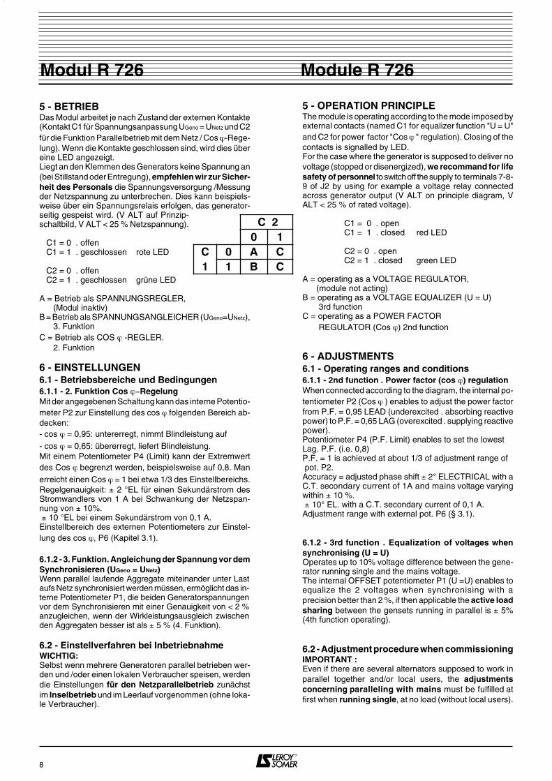
4 - R726 ANSCHLUSSPLAN 4 - R 726 CONNECTION DIAGRAM
7
Module R 726Modul R 726
C1P5
P6
1 2 3 4 5 6 7 8 9 10
123456789
10
12
1 2 3
1 2 3
3
ERREGERFELDEXCITER FIELD
SP
AN
NU
NG
SR
EG
LER
-
VO
LTA
GE
RE
GU
LAT
OR
E+ E-
U Err > MAX< MIN
X Y
STZ
SPANNUNGVOLTAGE
U
(5Ω
/ 50
Hz)
U = UVORSYNCHRONISIERUNG
SYNCHRONISING
(5Ω / 50 Hz)
Cos ϕ
R 726Brücken ST1/ST2 beiFehlen des Potentiometersanbringen
Fit jumpers ST1/ST2 if there is no remote potentiometer
ST1 ST2
J1
J2
400 V
100 V
0 V
NETZMAINS
C2
S2
S1
G
P1
P2
S2
P2
P2
S2
S2
Y
Y
S1 P1
P2
STROMWANDLER / CT… /1A - 3VA
TP / VT100/110V - 15VA
TP / VT 5VA
NE
TZ
ZU
SC
HA
LTU
NG
PA
RA
LLE
LIN
G
LOK
. VE
RB
RA
UC
HE
RLO
CA
L U
SE
R
Brücke (STZ) oder externes Potentiometeram Regler entfernenRemove jumper (STZ) or remote pot.on the voltage regulator
Spannungsrelais GeneratorVGEN
VALT
V GEN > MIN
ERREGER-RELAISEXCITATION MONITORING
* Die Klemmen der Regler-Steckverbinder sind von links nach rechtsangegeben und numeriert.* A.V.R.'s terminals are named like numbered from left to right.
R2 R1
Regler / A.V.R. RS 128A R 129 R 438 LS R448 R726 R130Klemmen *Terminals
R2
R1
5
4
5
4
1
2
3
2
3
2
1
2
Y
X
1000 Ω
470 Ω
400 V
10 0 V
0 V
P1
P1
S1
S1
VGEN
5 - BETRIEBDas Modul arbeitet je nach Zustand der externen Kontakte(Kontakt C1 für Spannungsanpassung UGeno = UNetz und C2für die Funktion Parallelbetrieb mit dem Netz / Cos ϕ-Rege-lung). Wenn die Kontakte geschlossen sind, wird dies übereine LED angezeigt. Liegt an den Klemmen des Generators keine Spannung an(bei Stillstand oder Entregung), empfehlen wir zur Sicher-heit des Personals die Spannungsversorgung /Messungder Netzspannung zu unterbrechen. Dies kann beispiels-weise über ein Spannungsrelais erfolgen, das generator-seitig gespeist wird. (V ALT auf Prinzip-schaltbild, V ALT < 25 % Netzspannung).
C1 = 0 . offen C1 = 1 . geschlossen rote LED C2 = 0 . offen C2 = 1 . geschlossen grüne LED A = Betrieb als SPANNUNGSREGLER, (Modul inaktiv)B = Betrieb als SPANNUNGSANGLEICHER (UGeno=UNetz), 3. FunktionC = Betrieb als COS ϕ -REGLER. 2. Funktion
6 - EINSTELLUNGEN6.1 - Betriebsbereiche und Bedingungen6.1.1 - 2. Funktion Cos ϕ−RegelungMit der angegebenen Schaltung kann das interne Potentio-meter P2 zur Einstellung des cos ϕ folgenden Bereich ab-decken:- cos ϕ = 0,95: untererregt, nimmt Blindleistung auf- cos ϕ = 0,65: übererregt, liefert Blindleistung.Mit einem Potentiometer P4 (Limit) kann der Extremwertdes Cos ϕ begrenzt werden, beispielsweise auf 0,8. Manerreicht einen Cos ϕ = 1 bei etwa 1/3 des Einstellbereichs.Regelgenauigkeit: ± 2 °EL für einen Sekundärstrom desStromwandlers von 1 A bei Schwankung der Netzspan-nung von ± 10%. ± 10 °EL bei einem Sekundärstrom von 0,1 A. Einstellbereich des externen Potentiometers zur Einstel-lung des cos ϕ, P6 (Kapitel 3.1).
6.1.2 - 3. Funktion. Angleichung der Spannung vor demSynchronisieren (UGeno = UNetz)Wenn parallel laufende Aggregate miteinander unter Lastaufs Netz synchronisiert werden müssen, ermöglicht das in-terne Potentiometer P1, die beiden Generatorspannungenvor dem Synchronisieren mit einer Genauigkeit von < 2 %anzugleichen, wenn der Wirkleistungsausgleich zwischenden Aggregaten besser ist als ± 5 % (4. Funktion).
6.2 - Einstellverfahren bei InbetriebnahmeWICHTIG:Selbst wenn mehrere Generatoren parallel betrieben wer-den und /oder einen lokalen Verbraucher speisen, werdendie Einstellungen für den Netzparallelbetrieb zunächstim Inselbetrieb und im Leerlauf vorgenommen (ohne loka-le Verbraucher).
5 - OPERATION PRINCIPLEThe module is operating according to the mode imposed byexternal contacts (named C1 for equalizer function "U = U"and C2 for power factor "Cos ϕ " regulation). Closing of thecontacts is signalled by LED.For the case where the generator is supposed to deliver novoltage (stopped or disenergized), we recommand for lifesafety of personnel to switch off the supply to terminals 7-8-9 of J2 by using for example a voltage relay connectedacross generator output (V ALT on principle diagram, VALT < 25 % of rated voltage). C1 = 0 . open C1 = 1 . closed red LED C2 = 0 . open C2 = 1 . closed green LED A = operating as a VOLTAGE REGULATOR, (module not acting)B = operating as a VOLTAGE EQUALIZER (U = U) 3rd functionC = operating as a POWER FACTOR REGULATOR (Cos ϕ) 2nd function
6 - ADJUSTMENTS6.1 - Operating ranges and conditions6.1.1 - 2nd function . Power factor (cos ϕ) regulationWhen connected according to the diagram, the internal po-tentiometer P2 (Cos ϕ ) enables to adjust the power factorfrom P.F. = 0,95 LEAD (underexcited . absorbing reactivepower) to P.F. = 0,65 LAG (overexcited . supplying reactivepower).Potentiometer P4 (P.F. Limit) enables to set the lowest Lag. P.F. (i.e. 0,8)P.F. = 1 is achieved at about 1/3 of adjustment range of pot. P2.Accuracy = adjusted phase shift ± 2° ELECTRICAL with aC.T. secondary current of 1A and mains voltage varyingwithin ± 10 %. ± 10° EL. with a C.T. secondary current of 0,1 A.Adjustment range with external pot. P6 (§ 3.1).
6.1.2 - 3rd function . Equalization of voltages whensynchronising (U = U)Operates up to 10% voltage difference between the gene-rator running single and the mains voltage.The internal OFFSET potentiometer P1 (U =U) enables toequalize the 2 voltages when synchronising with aprecision better than 2 %, if then applicable the active loadsharing between the gensets running in parallel is ± 5%(4th function operating).
6.2 - Adjustment procedure when commissioningIMPORTANT :Even if there are several alternators supposed to work inparallel together and/or local users, the adjustmentsconcerning paralleling with mains must be fulfilled atfirst when running single, at no load (without local users).
8
Module R 726Modul R 726
C 20 1
C 0 A C1 1 B C
6.2.1 - VorprüfungZunächst muß gewährleistet sein, daß das Erregersystemdes Generators so eingestellt wurde, daß es ohne Schwie-rigkeiten im gesamten Einstellbereich der Netzspan-nung für den gewünschten Cos ϕ betrieben werdenkann (siehe entsprechendes Handbuch).KOMPOUND-ERREGUNG (ACTR . RBC): Der Kom-pound ist so einzustellen, daß im Inselbetrieb die Span-nung auf die höchste Spannung des Netzparallelbetriebsansteigen kann (z. B. 430 V für 400 V Nennspannung).Weiterhin muß überprüft werden, daß der Spannungsreg-ler bis zur niedrigsten Spannung eingestellt werden kann(z. B. 370 V für 400 V Nennspannung).ERREGUNG SHUNT + BOOSTER: Der Booster (Strom-wandler) muß bei Netzparallelbetrieb kurzgeschlossenoder seine Wirkung mittels eines Boostermodulators be-grenzt sein.BEI ALLEN REGLERN muß die Einstellung des Unterdreh-zahlschutzes (oder des LAM) überprüft werden. Er muß 2 Hz unter der niedrigsten Frequenz eingestelltwerden, für die das Synchronisiergerät das Zuschaltenzuläßt.Die STABILITÄT des Spannungsreglers muß bei Inselbe-trieb eingestellt werden.
6.2.2 - Einstellung der Spannung im InselbetriebExternes Potentiometer P5 auf mittlere Position eingestellt.Die Generatorspannung über das interne Spannungspo-tentiometer des Reglers einstellen.
6.2.3 - Spannungsangleichung vor der NetzzuschaltungMeßgerät: Voltmeter 500 V für Netz- und Generatorspan-nung.Erregerspannung (UErr) = analoges Voltmeter kalibriert auf30/50 V DC.Generator anlaufen lassen und Drehzahl so einstellen,daß sich Normalbedingungen für das Zuschalten ergeben. Kontakt C1 schließen: die rote LED muß leuchten.WENN DIE SPANNUNG ABFÄLLT ODER STARK AN-STEIGT: ANSCHLUSSFEHLER ZWISCHEN SPAN-NUNGSREGLER UND MODUL. GENERATOR ANHAL-TEN UND DIE BEIDEN DRÄHTE AN DEN KLEMMEN 1UND 2 DER KLEMMENLEISTE J1 DES MODULS R726TAUSCHEN.Abwechselnd Netzspannung und Generatorspannung mitdemselben Voltmeter messen. Die Differenz durch Einstellen des Potentiometers P1 desModuls (U = U) reduzieren.Ist die Generatorspannung instabil, muß die Erregerspan-nung Uexc beobachtet werden und das Potentiometer P3zur Einstellung der STABILITÄT des Moduls R 726 ent-sprechend eingeregelt werden.
6.2.4 - Einstellung des Cos ϕAusgangspositionen:- externes Potentiometer Cos Ø (P6) = Mittelstellung,- internes Potentiometer (P2) auf 1/4 seines Bereiches vonlinks ausgehend einstellen, - Potentiometer P4 (Limit) auf RechtsanschlagSYNCHRONISIEREN UND ZUSCHALTEN,DIE GRÜNE LED MUSS LEUCHTEN.
STEIGT IM MOMENT DES ZUSCHALTENS DER AUS-GANGSSTROM DES GENERATORS STARK AUF EI-NEN HOHEN WERT AN ODER BRICHT DIE ERREGER-SPANNUNG ZUSAMMEN, MUSS DER GENERATORSOFORT VOM NETZ GETRENNT WERDEN.
6.2.1 - Preliminary checksAt first ensure that the excitation system of the machine hasbeen properly adjusted in order so operate in the wholevoltage variation range of the mains at the requestedpower factor (see advisable leaftet).COMPOUND EXCITATION (ACTR . RBC) : the compoundsystem must be adjusted high enough to be able to operatesingle on load at the highest main voltage (i.e. 430 V forrated 400 V). Check also if the voltage regulator enables todrop the voltage to the lowest mains voltage level (i.e. 370Vfor rated 400 V).SHUNT + BOOSTER EXCITATION : the booster (currenttransformer) shall be either short-circuited when parallelingwith the mains, or its action shall be reduced by a boosterlimitor/ monitor.ON ALL AVRs, check the setting of underspeed protectionor LAM : the threshold level must be adjusted 2 Hz belowthe lowest frequency for which the synchronizer allowsparalleling.The STABILITY of the voltage regulator must be set whenoperating single.
6.2.2 - Adjustment of voltage in single operation Remote potentiometer P5 in middle position.Adjust the generator's output voltage by moving the in-ternal voltage adjust. pot. of the voltage regulator.
6.2.3 - Equalization of voltages when synchronisingApparatus = mains/generator voltages : digital voltmeter500 V.Excitation voltage (Uexc) : analogical index voltmeter 30/50V DC.Start the genset and adjust speed to meet normal synchro-nising conditions.Close contact C1 : the red LED should light up.IF THE GENERATOR VOLTAGE DROPS OR RAISESFAR FROM MAINS VOLTAGE : BAD CONNECTIONBETWEEN THE AVR AND THE MODULE . STOP ANDTRANSPOSE THE 2 LEADS CONNECTED ON TERMI-NALS 1 and 2 OF TERMINAL STRIP J1 ON MODULER 726.Measure alternatively voltages on mains and generator si-de with the same voltmeter.Reduce difference by moving potentiometer P1 (U = U) onthe module.If the genrator voltage is unstable, adjust on potentiome-ter P3 on the module, observing the excitation voltageUexc, until stabilisation.
6.2.4 - Power factor (cos ϕ) adjustmentInitial settings :- external power factor pot. P6 = middle,- internal power factor pot. P2 = 1/4 of range, when startingfully anticlockwise.- internal pot (Limit) P4 fully clockwise. SWITCH ON PARALLEL WHEN SYNCHRONISED The green LED should light up.
IF JUST AFTER SWITCHING ON THE LINE CURRENTRISE TO A RATHER HIGH VALUE OR IF THE EXCI-TATION VOLTAGE DROPS, SWITCH OFF IMMEDIATE-LY AND STOP GENSET.
9
Module R 726Modul R 726
ANSCHLUSSFEHLER (PHASEN) ODER STROMWAND-LER VERTAUSCHT (SEKUNDÄREINGANG S1 UND S2TAUSCHEN). . den Generator durch Erhöhen der Drehzahl (kW) bela-sten und auf 60 % der Nennlast einstellen. . auf den gewünschten Extremwert des Cos ϕ mit dem in-ternen Potentiometer P4 (Limit) einstellen: die gelieferteBlindleistung (verringert den Cos ϕ) wird durch Drehen vonP2 im Uhrzeigersinn erhöht (siehe Anmerkung), . wenn sich der gewünschte cos ϕ nicht erreichen läßt =ANSCHLUSSFEHLER (PHASEN) . INSTABILITÄT: = Potentiometer P3, gegebenenfalls Po-tentiometer STABILITÄT des Reglers einstellen . Auf 90% (+kW) der Nennlast (kW) einstellen . Den Nennwert des Cos ϕ mit Hilfe des Potentiometers P2(cos ϕ) einstellen.ANMERKUNG:1) Ist kein Phasenmeßgerät oder Cos ϕ −Meter vorhanden,muß der zu erreichende Statorstrom (IS) für
den gewünschten Cos ϕ berechnet werden kW = Angabe Wattmeter (kW), UNetz = reelle Netzspannung (V)
2) Einstellung des Cos ϕ = 1: bei einem Cos ϕ = 1 ist derStatorstrom IS bei konstanter Wirkleistung (kW) am niedrig-sten: auf den Minimalwert einstellen.
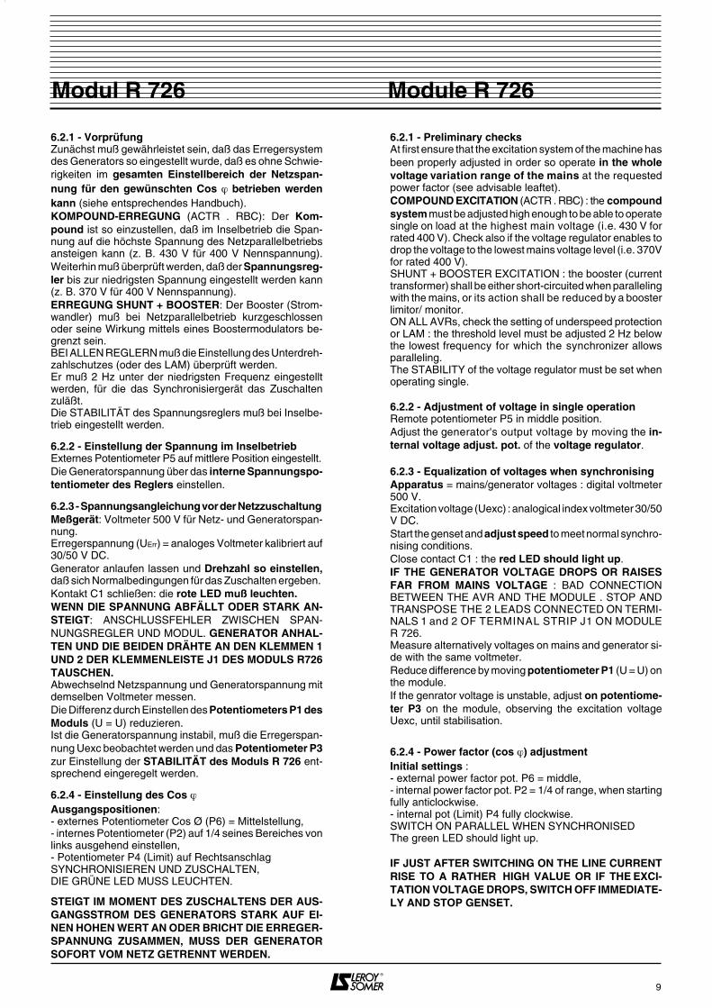
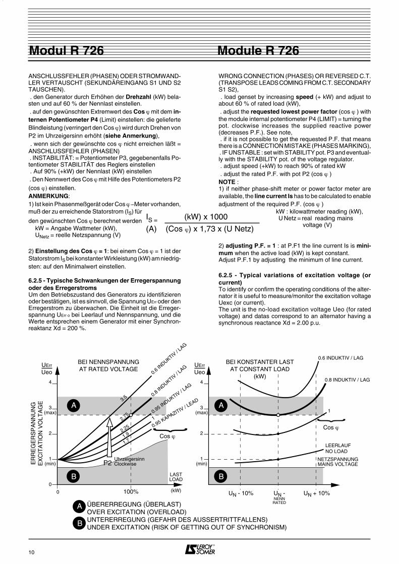
6.2.5 - Typische Schwankungen der Erregerspannungoder des ErregerstromsUm den Betriebszustand des Generators zu identifizierenoder bestätigen, ist es sinnvoll, die Spannung UErr oder denErregerstrom zu überwachen. Die Einheit ist die Erreger-spannung UErr o bei Leerlauf und Nennspannung, und dieWerte entsprechen einem Generator mit einer Synchron-reaktanz Xd = 200 %.
WRONG CONNECTION (PHASES) OR REVERSED C.T.(TRANSPOSE LEADS COMING FROM C.T. SECONDARYS1 S2), . load genset by increasing speed (+ kW) and adjust toabout 60 % of rated load (kW), . adjust the requested lowest power factor (cos ϕ ) withthe module internal potentiometer P4 (LIMIT) = turning thepot. clockwise increases the supplied reactive power(decreases P.F.). See note, . if it is not possible to get the requested P.F. that meansthere is a CONNECTION MISTAKE (PHASES MARKING), . IF UNSTABLE : set with STABILITY pot. P3 and eventual-ly with the STABILITY pot. of the voltage regulator. . adjust speed (+kW) to reach 90% of rated kW . adjust the rated P.F. with pot P2 (cos ϕ )NOTE :1) if neither phase-shift meter or power factor meter areavailable, the line current Is has to be calculated to enableadjustment of the required P.F. (cos ϕ )
kW : kilowattmeter reading (kW), U Netz = real reading mains voltage (V)
2) adjusting P.F. = 1 : at P.F1 the line current Is is mini-mum when the active load (kW) is kept constant.Adjust P.F.1 by adjusting the minimum of line current.
6.2.5 - Typical variations of excitation voltage (orcurrent)To identify or confirm the operating conditions of the alter-nator it is useful to measure/monitor the excitation voltageUexc (or current).The unit is the no-load excitation voltage Ueo (for ratedvoltage) and datas correspond to an alternator having asynchronous reactance Xd = 2.00 p.u.
10
Module R 726Modul R 726
IS = (kW) x 1000
(A) (Cos ϕ) x 1,73 x (U Netz)
0
1(min)
2
3(max)
4
BEI NENNSPANNUNGAT RATED VOLTAGE
UErr
Ueo
0 100%
LASTLOAD
3.5
2.75
2.25
1.9
1.7
0.6 INDUKTIV
/ LAG
0.8 INDUKTIV
/ LAG
0.95 INDUKTIV / L
AG
1
0.95 KAPAZITIV / LEAD
}
Cos ϕ
P2UhrzeigersinnClockwiseE
RR
EG
ER
SP
AN
NU
NG
EX
CIT
AT
ION
VO
LTA
GE
1(min)
2
3(max)
4
BEI KONSTANTER LASTAT CONSTANT LOAD
(kW)
UN - 10%
}
Cos ϕ
(kW)
NETZSPANNUNGMAINS VOLTAGE
0.6 INDUKTIV / LAG
0.8 INDUKTIV / LAG
1
LEERLAUFNO LOAD
UN -NENNRATED
UN + 10%
A
B
A
B
ÜBERERREGUNG (ÜBERLAST) OVER EXCITATION (OVERLOAD) UNTERERREGUNG (GEFAHR DES AUSSERTRITTFALLENS) UNDER EXCITATION (RISK OF GETTING OUT OF SYNCHRONISM)
UErr
Ueo
A
B

7 - SPEZIFISCHE SCHUTZVORRICHTUN-GEN BEI NETZPARALLELBETRIEB . Spannungsrelais V ALT (Vorliegen Generatorspannung)Möglichkeit der Unterbrechung der Messung / Spannungdes Moduls im Stillstand: ZUR SICHERHEIT DES PERSO-NALS . Differentialspannungsrelais (oder Synchronisiergerät)(UNetz / UGenerator): Verhindern des Zuschaltens bei zugroßer Spannungsdifferenz . Relais für MAXIMALE ERREGUNG (Überlast) und MINI-MALE ERREGUNG (Gefahr des Außertrittfallens) Span-nung oder Strom. . Relais für MAXIMALEN STATORSTROM (thermisch)oder THERMOFÜHLER (Überlast Stator), . KURZUNTERBRECHUNGEN (KUs): alle vorhandenenund verfügbaren Mittel sind einzusetzen, um ein erneutesEinschalten zu verhindern oder das Trennen vom Netz beikurzzeitigem Ausfall der Netzspannung zu erzwingen.
ACHTUNG: DURCH EIN EINZIGES FALSCHES ZU-SCHALTEN ZUM NETZ IN PHASENOPPOSITION KANNDER GENERATOR ZERSTÖRT WERDEN.
8 - PARALLELBETRIEB MIT EINEM ODERMEHREREN GENERATOREN (GETRENNTVOM NETZ)Derselbe Stromwandler wie für Modul R726 kann verwendetwerden. Die Eingänge für den Stromwandler des Reglersund des Moduls müssen unter Beachtung der vorgesehe-nen Stromrichtung für den Regler in Serie geschaltet wer-den.
ANMERKUNG: Die Spannungsmessung der Regler mußbei einem Stromwandler auf Phase 1 zwischen den Pha-sen 2 und 3 erfolgen, wie bei Modul R726.
9 - NETZPARALLELSCHALTUNG VON 2(ODER MEHREREN) GENERATOREN, DIEUNTEREINANDER PARALLEL BETRIEBENWERDEN - 4. FUNKTION(Transfer der Last ohne Unterbrechung)Mit dem Modul R726 verwendet die Synchronisierungs-phase die 3. Funktion (U = U) - C1 geschlossen.Die 4. Funktion ist untrennbar mit der 3. Funktion verbun-den und wird beim Zuschalten außer Betrieb gesetzt (C2geschlossen).Wenn die Synchronisierung unter Last erfolgt (Generatorim Inselbetrieb oder Parallelbetrieb mit anderen Generato-ren), führt die 4. Funktion eine Spannungsabweichung voneinigen % (1...3) ein, die von der Abweichung zwischeneingestelltem cos ϕϕϕϕ (2. Funktion) und cos ϕϕϕϕ der Last ab-hängt.
10 - COS-Ø-REGELUNG EINER ANLAGE,DIE VOM NETZ GESPEIST WIRD - Erregung Shunt oder AREP.Der Generator muß so dimensioniert sein, daß er die ge-samte Wirkleistung und Blindleistung, die von der Anlagegefordert wird, liefert (DIE NORMALEN KONDENSATO-REN ZUR KOMPENSATION DES LEISTUNGSFAK-TORS MÜSSEN ELIMINIERT WERDEN).
Ist die Dimensionierung des Generators nicht ausreichend,muß zusätzlich ein Begrenzungswiderstand RL in Reihemit dem Erregerfeld installiert und eingestellt werden (RL =etwa doppelter Widerstand des Erregerfelds), der bei
7 - SPECIFIC PROTECTIONS REQUIREDWHEN PARALLELING WITH THE MAINS . VOLTAGE relay V ALT (alternator output voltage) to cutoff the mains supply/sensing to the module when thegenerator is stopped : LIFE SAFETY. . differential voltage (U MAINS . U ALT) relay or synchroni-ser : prohibiting synchronisation for a too large difference, . MAXIMUM EXCITATION (overload) or MINIMUM EXCI-TATION (risk of putting OUT OF SYNCHRONISM) DCvoltage or current relays. . MAXIMUM LINE CURRENT (THERMICAL) OR THER-MAL SENSORS (stator overload), . MICROBREAKS : all available means shall be applied toimpede reconnection or force switching off in case o f mainsvoltage microbreaks.
CAUTION : THE LIFE DURATION OF A GENERATORPARALLELED WITH MAINS MAY BE ONLY ONECONNECTION COMPLETELY OUT OF PHASE.
8 - PARALLEL OPERATION WITH OTHERGENERATOR(S) (INSULATED FROM MAINS)
The same C.T. as for Module R 726 may be used : thecurrent sensing imputs of AVR and of the module must beconnected in series, with respect to the connectiondiagram of the voltage regulator.
NOTE : the voltage sensing of the voltage regulator with aC.T. located on phase 1, must be connected across phases2 and 3, as for the module R726.
9 - SYNCHRONISING WITH MAINS 2 (ORMORE) ALTERNATORS OPERATING INPARALLEL TOGETHER - 4th FUNCTION(source change-over without break)With the module R726, the synchronisation is done byusing the 3rd function (U = U) - C1 closed.The 4th function cannot be dissociated from the 3rd func-tion : it is only out of duty when paralleling (C2 closed).Whenever the synchronisation takes place when the alter-nator is loaded (single or paralleling with other(s)) theaction of the 4th function is so that it introduces a voltageshift of % (1...3) depending of the gap between the ad-justed P.F. (2nd function) and the real load P.F.
10 - MONITORING THE POWER FACTOR OFA PLANT SUPPLIED BY THE MAINS- Shunt or AREP excitation only.The generator should be rated taking into account the who-le reactive power absorbed by the plant (EVENTUAL P.F.COMPENSATION CAPACITORS MUST BE DIS-CONNECTED).
If the rating of generator is too weak to supply the wholereactive power of the plant, an adjustable limiting resistorRL must be connected in series with the exciter field (RLvalue : = about 2 times the resistance of exciter field), tobe shorted when the generator operates single.
11
Module R 726Modul R 726
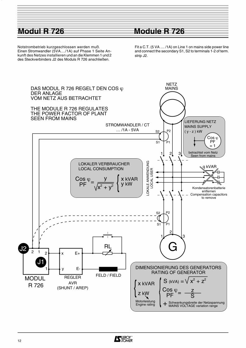
Notstrombetrieb kurzgeschlossen werden muß.Einen Stromwandler (5VA..../1A) auf Phase 1 Seite An-kunft des Netzes installieren und an die Klemmen 1 und 2des Steckverbinders J2 des Moduls R 726 anschließen.
Fit a C.T. (5 VA .... /1A) on Line 1 on mains side power lineand connect the secondary S1, S2 to terminals 1-2 of term.strip J2.
12
Module R 726Modul R 726
1
1
2
2
3
3
NETZMAINS
S1
S2
G
P1
P2
S1
S2
FELD / FIELD
q kVAR
betrachtet vom NetzSeen from mains
Kondensatorenbatterieentfernen
Compensation capacitorsto remove
DAS MODUL R 726 REGELT DEN COS ϕ DER ANLAGE VOM NETZ AUS BETRACHTET
THE MODULE R 726 REGULATESTHE POWER FACTOR OF PLANTSEEN FROM MAINS
LOK
ALE
AN
WE
ND
UN
GLO
CA
L U
SE
R
STROMWANDLER / CT… /1A - 5VA
Cos ϕPF =
y
x2 + y2 { x kVARy kW
J22 1 2
1
x
y
E+
E-
RL
MODUL R 726
REGLERAVR
(SHUNT / AREP)
S (kVA) = x2 + z2
{ x kVAR
z kW
MotorleistungEngine rating
{DIMENSIONIERUNG DES GENERATORS
RATING OF GENERATOR
Cos ϕPF = z
SSchwankungsbreite der NetzspannungMAINS VOLTAGE variation range+
LOKALER VERBRAUCHERLOCAL CONSUMPTION
Cos ϕPF= 1
LIEFERUNG NETZMAINS SUPPLY( y - z ) kW
P1
P2
J1

11 - BEHEBUNG VON STÖRUNGENEs wird vorausgesetzt, daß das komplette System bereitskorrekt funktioniert hat.
11.1 - Überprüfung des Spannungsreglers(siehe entsprechendes Handbuch) . die 2 Leiter der Verbindung zum Modul R 726 abklemmen(Klemmen 1-2 von J1). Die 2 Klemmen x-y des Reglers, diefür den Anschluß des externen Potentiometers zur Span-nungseinstellung vorgesehen sind, kurzschließen. . den Generator im Inselbetrieb bei Leerlauf und seinerNenndrehzahl laufen lassen. Wenn die Maschine eine ge-regelte Spannung liefert (durch Betätigen des internen Po-tentiometers zur Einstellung der Reglerspannung prüfen),GEHT DIE STÖRUNG NICHT VOM SPANNUNGSREG-LER AUS.
11.2 - Überprüfung des Moduls R 726Prüfen, daß alle erforderlichen Informationen an denKlemmen des Moduls ankommen: NETZSPANNUNG,GENERATORSPANNUNG, STROM DES STROM-WANDLERS (R < 2 Ω), KONTAKTE C1 und C2 (R < 5 Ω),EXTERNE POTENTIOMETER. Weiterhin prüfen, daß dieVerbindung zum Spannungsregler nicht unterbrochen ist.WENN DER SPANNUNGSREGLER IN ORDNUNG ISTUND ALLE INFORMATIONEN AM MODUL ANKOMMEN,IST DIESES DEFEKT.
12 - STATISCHE EINSTELLUNGEN DES MO-DULS R 726
Siehe nachstehenden Schaltplan und die Liste des erfor-derlichen Materials.Die Einstellungen können entweder am Generator inInselbetrieb bei Leerlauf oder im Stillstand bei Span-nungsversorgung durch das Netz vorgenommen wer-den. Die Verbindung zum Spannungsregler abklemmen (Klem-men 1-2 des Steckverbinders J1 des Moduls).An diese Klemmen nach Möglichkeit ein digitales Voltmeteranschließen (kal. ± 2 V DC),Die entsprechenden Klemmen des Reglers (x-y) kurz-schließen,die Testschaltung entsprechend dem Schaltplan verka-beln.Die Schalter und Umschalter können durch Stecker oderPrüfspitzen ersetzt werden.Die Drossel L (65 mH) ist nur erforderlich bei einer Vorein-stellung auf cos ϕ ≠ 1 und der Einstellung auf den niedrigst
möglichen cos ϕ übererregt.
Für eine Voreinstellung auf cos ϕ = 1 ist nur ein Widerstandvon 27 Ω / 50 W erforderlich.Die Regelgenauigkeit liegt bei etwa ± 2% für die 3. FUNK-TION (U = U) und bei ± 5 °EL für die 2. FUNKTION (cos ϕ ),jeweils in Abhängigkeit von der Qualität des verwendetenSpannungswandlers.
DASSELBE VERFAHREN DIENT AUCH ZUR ÜBER-PRÜFUNG DES ZUSTANDS DES MODULS: WENN DASMODUL NICHT WIE BESCHRIEBEN REAGIERT, IST ESDEFEKT.
11 - TRACKING THE ORIGIN OF A MISFUNC-TIONThe complete system is supposed to have been previouslyoperating satisfactorily.
11.1 - Checking automatic voltage regulator(see applicable handbook) . disconnect the 2 wires linking to the Module R 726 (Term.1-2 of J1) and short the 2 term. x-y of the AVR which arenormally for the connection of a remote voltage adjust. pot., . drive the generator at rated speed, operating single at no-load. If the machine supplies a regulated voltage (to bechecked by turning the internal voltage adjustment poten-tiometer) that means that THE MISFUNCTION IS NOTDUE TO THE VOLTAGE REGULATOR.
11.2 - Checking module R 726 Check if all the required informations reach the termi-nals of the module : MAINS and GENERATOR VOL-TAGES, C.T. SECONDARY CURRENT (R < 2 ohms),CONTACTS C1 and C2 (R < 5 ohms), REMOTE POTEN-TIOMETERS, and that connection to the voltage regulatoris not open.IF THE AVR IS GOOD AND ALL INFORMATIONS IN-COME MODULES TERMINALS IS MEANING THAT THEMODULE IS FAILED.
12 - STATIC ADJUSTMENTS ON MODULE R 726See diagram and components list here after.The adjustments may be done either on the generatoroperating single at no load, or standing and suppliedby the mains.Disconnect the 2 wires (OUTPUT) linked to the AVR (onterminals 1-2 of terminal strip J1 of the module).Connect to these terminals a DC voltmeter, preferably digi-tal (cal ± 2V DC) and short the 2 terminals x-y of AVR whichwere linked to the module,wire the test assembly according to the diagram,the switches and c/o switch may be replaced by insulatedplugs or clips.The choke (reactor) L ( 65mH) is only necessary for a pre-adjustment at a power factor ≠ 1 and for adjustment of the li-mit lowest P.F. LAG. for P.F. = 1, only a fixed resistor of 27ohms /50 W is ne-cessary.Precision of such static adjustments is about ± 2% for the3rd FUNCTION (U=U) and of ± 5° EL for the 2nd FUNC-TION (P.F., Cos ϕ), much depending of the quality of avai-lable voltage transformer.
THE SAME PROCEDURE IS APPLICABLE FOR CHEC-KING THE CONDITION OF MODULE : IF THE MODULEIS NOT REACTING AS DESCRIBED, THAT MEANS IT ISFAILED.
13
Module R 726Modul R 726

14
Module R 726Modul R 726
S2
P5 P6
1 2 3 4 5 6 7 8 9 10
123456789
10
SPANNUNGS-REGLER
X Y
R 726
ST1 ST2
J1
J2
400 V
0 VLED
P4 - LIMIT
P2 - Cos ϕ
P1U = U
ROT/RED
GRÜN /GREEN
"U = U"
"Cos ϕ"
VOLTAGEREGULATOR
S1
V1
1
2
(UCOM)
Kal ± 2V
400 V
0 V
S3
S0
P2 P1
S2
TP100 VA(200-250)/24 V
24V
0(N)
1 2 3
V2(UTOT)
(B)C4
15 Ω
R1 R2 - 15 Ω
(A)
L
Cos ϕPF = UR
UTOT
VERWENDETES MATERIAL COMPONENTSDigitales Voltmeter ± 2V DCVoltmeter ~ kal. 30 VAus-Schalter 500 V / 5 A - 2poligAus-Schalter 250 V / 5 A - 1 oder 2poligFester Widerstand 15 Ω / 50 WPotentiometer 15 Ω / 50 WDrossel 65 mH - 1.5 A - 50 / 60 Hz *Schalter 2 Positionen A-B,1 Weg, 250V- 5 A"Schutz"-Trafo 110 - 220 / 24 V - 100 VA oder 220/380 - 24V - 100 VA* Kann durch einen Kondensator C mit 150 μFersetzt werden; in diesem Fall S1/S2 desTransformators TP vertauschen.
Digital voltmeter range ± 2V DCAC / RMS voltmeter cal 30 V500 V / 2 pole switch (5 A)Switches 250 V / 5 A, 1 or 2 poleFixed resistor 15 Ω / 50 WRheostat 15 Ω / 50 W Choke (reactor) 65 mH - 1.5 A - 50 / 60 Hz *Change over switch 2 positions A - B, 1 way, 250 V - 5 A "Safety" voltage transformer 110 - 220 / 24 V - 100 VA or 220/380 - 24V - 100 VA* May be replaced by a capacitor C of about 150 μF.Then transpose S1/S2 on voltage transformer TP.
V1V2S0
S1, S2, S3R1R2L
CHTP
(350-460V ; 50/60 Hz)NETZ oder GENERATORMAINS or GENERATOR
FUNKTION / FUNCTIONS0 x S1 U = U (S0 x S1 = S0 und S1 GESCHLOSSEN / S0 and S1 CLOSED)
S0 x S1 x S3 x (C4 (A) oder/or C4 (B)) = 4. Funktion / 4th function
S0 x S2 x S3x C4 (A) Cos ϕ = 1 (S0 x S2 x S3 = S0 und S2 und S3 GESCHLOSSEN / S0 and S2 and S3 CLOSED)x C4 (B) Cos ϕ = 1
X,Y kurzschließenShort-circuit X,Y
Simulation desSchaltkreises zurStrommessungSimulation ofcurrent sensingcircuit
P3 - STAB
S1
V2 Cos ϕ = 1
Cos ϕ = 1
(UR)
}

EINSTELLUNG DER 3. FUNKTION (U = U) . Ausgangsposition der externen Potentiometer (wenn vor-handen) = mittlere Stellung, . Schalter S0 schließen (Speisung), . Schalter S1 schließen (U=U), . die rote LED leuchtet, . das Voltmeter VI zeigt eine Spannung U COM an, dieentweder etwa (-1 V) oder etwa (+1 V) beträgt, . durch Drehen des Potentiometers P1 (U = U) von linksnach rechts geht die Spannung UCOM von einem dieserExtremwerte zum anderen über, . der Einstellpunkt ist die Stellung von P1, bei der das Volt-meter V1 eine Spannung anzeigt, die zwischen (+) und(-) 0,5 V hin- und her schaltet.
EINSTELLUNG DER 2. FUNKTION (COS ϕ) a) Einstellung von P4 . Potentiometer P2 (cos ϕ) und P4 (LIMIT) auf Rechtsan-schlag drehen. . Schalter S2 (cos ϕ) schließen, . die grüne LED leuchtet, . Umschalter C4: B (cos ϕ ≠1), . Schalter S3 (Simulation des Stromwandlers) schließen, . den gewünschten Grenzwert des cos ϕ einstellen, . Potentiometer P4 (LIMIT) drehen, bis das Voltmeter V1eine Spannung angibt, die zwischen (+) und (-) 0,5 V an-zeigt. b) Einstellung von P2 (Nennwert des cos ϕ)C4 in Position B oder A: den gewünschten Nennwert descos ϕ einstellen, P2 wie zuvor für P4 beschrieben einstel-len. . alle Schalter öffnen und gemäß Schaltplan an-schließen.
4. FUNKTION(Parallelbetrieb während der Spannungsangleichung)Eine Einstellung der 4. Funktion ist nicht möglich, es kannjedoch überprüft werden, ob sie aktiv ist.Es wird vorausgesetzt, daß die Einstellung der 2. und 3.Funktion wie zuvor beschrieben vorgenommen wurde.S0 und S1 schließen (3. Funktion U = U).Das Voltmeter V1 zeigt eine Spannung UCOM an, die zwi-schen + oder -0,5V liegt.Über C4 einen anderen als den eingestellten cos ϕϕϕϕ aus-wählen:C4 (A), wenn der cos ϕ auf C4 (B) eingestellt ist, oder C4(B), wenn der cos ϕ auf C4 (A) eingestellt wurde.S3 schließen: die vom Voltmeter V1 angezeigte SpannungUCOM muß auf ±1 Volt übergehen. Dies zeigt an, daßdie 4. Funktion aktiv ist.
ADJUSTMENT OF THE 3RD FUNCTION (U = U) . initial setting of external potentiometers (if any) = midposition, . switch on S0 (supply switch), . switch on S1 (U = U Command), . the red LED lights up. . the voltmeter V1 indicates a voltage UCOM either about(-1 volt) or about (+ 1 volt).By rotating potentiometer P1 (U = U) clockwise from fullyanticlockwise position, voltage UCOM triggers from one ofthe maximum negative (or reverse) to the other maximum.The setting position of P1 is that one where the voltmeter V1indicates a voltage changing from (+) to (-) 0,5 V.
ADJUSTMENT OF THE 2ND FUNCTION (COS ϕ) a) adjustment of P4 . set potentiometers P2 (Cos ϕ) and P4 (LIMIT) fully clock-wise. . close switch S2 (COS ϕ FUNCTION COMMAND), . the green LED lights up, . change over switch in position : B (PF≠1), . switch on S3 (circuit simulating C.T.), . adjust to the required P.F. (no adjustment for P.F. = 1), . rotate potentiometer P4 (LIMIT) until to reach a positionwhere voltmeter V1 indicates a voltage tilting from (+) to (-)0,5 Volt. b) adjustment of P2 (rated P.F.)C4 in position B or A - Adjust the required rated P.F.,proceed with pot P2 as previously with P4.. switch off all the switches and reconnect accordingrelevant diagram.
4th FUNCTION(Parallel operation with other(s) generator(s) during vol-tage equalization)There is no adjustment for the 4th function, but it is possibleto check it is acting.The adjustment of 2nd and 3rd functions are supposed tohave been performed as described precedently.Close S0 and S1 (3rd function U = U).The voltmeter V1 should indicate a voltage UCOM comprisedbetween + or - 0.5V.Select with switch C4 a power factor different fromwhich has been adjusted :C4 (A) if the power factor has been adjusted or C4 (B)position ; or C4 (B) if the power factor has been adjusted onC4 (A) position.Close S3 : the voltage UCOM indicated by the voltmeter V1should change to ± 1 Volt, showing tha the 4th function isacting.
15
Module R 726Modul R 726

13 - NULLUNGSARTDie Nullungsart hat keinen Einfluß auf den Betrieb des Mo-duls.Wenn die Statorwicklung nicht in 2/3-Schritt ausge-führt ist, und die Nulleiter des Transformators und des Ge-nerators direkt oder über die Erde angeschlossen sind,muß in Reihe mit dem Nulleiter eine Begrenzungsdros-sel der Stromoberschwingungen angebracht werden.Wenn X ( Ω ) der Blindwiderstand der Drossel und L (HEN-RY) ihre Induktivität, gilt: X = 314 x L bei 50 Hz und 377 x Lbei 60 Hz.Die Stromoberschwingung im Nulleiter Ih beträgt dann:
U (V)I h = 0,038 x (U SPANNUNG ZW. PHASEN) X (Ω)
DAZU KOMMT DER HOMOPOLARE STROM I o, DERDURCH SCHIEFLASTEN BEDINGT IST.
I NULL = V (IO)2 + (IH)2 (Ampere effektiv)
14 - MESSUNG DER SPANNUNGEN UNDSTRÖME AUSSERHALB DER STANDARD-BEREICHE DES MODULS R 726
Es werden Anpassungstransformatoren verwendet, diewie folgt dimensioniert sind:
14.1 - Spannungstransformatoren (TP)Thermische Dimensionierung 50 VA - 50/60Hz Primärspannung: Spannung, die am TP anliegt oder Nie-derspannungen ≠ 230 - 250 V und 380 - 480 V (100 - 110 -120 - 500 - 600V)Sekundärspannung: 220 oder 400 V.
14.2 - Stromwandler: (T.I.)3 VA - Klasse 1Primärstrom: 5ASekundärstrom: 1A
14.3 - Sollwerte der TransformatorenTP : Primärspannungen 200 - 240 V : ............ 500 - 600 V : ............(Sekundärspannung 100-120 V)
T.I. : Stromwandler: .......................
13 - NEUTRAL LINE STATUSThe neutral line status has no influence on the module ope-ration.Adversely, if the winding pitch of the stator winding ofthe alternator is different from 2/3, and the neutral of themains transformer and of the generator a connected toge-ther either directly or through the carthing circuit, an har-monic current limiting choke (reactor) must be installedin series with the generator neutral connection.If X ( ohms ) is the reactance of the choke and L (HENRY) itsinductance : X = 314 x L at 50 Hz and 377 x L at 60 Hzthe harmonic current in neutral line Ih will be = U(V)I h = 0,038 x (U LINE TO LINE VOLTAGE) X (ohms )
To this current is adding the zero sequence current I o dueto load unbalance (LN loads):
I neutral (Amperes R.M.S.) = V (IO)2 + (IH)2
14 - MEASUREMENT OF VOLTAGES ANDCURRENTS OUT OF STANDARD RANGESOF MODULE R 726
Adapting transformers shall be used, rated as follows.
14.1 - Voltage transformers (V.T.)Thermal rating 50 VA - 50/60 Hz.Primary voltage : the voltage available from measurementvoltage transformer (HV) or low voltages differing from 200- 250 V or 380 - 480 V (i.e. 100 - 110 - 120 - 500 - 600V) Secondary voltage : 220 or 400 V.
14.2 - Current transformer : (C.T.)3 VA - classe 1Primary current: 5ASecondary current : 1A
14.3 - References of available transformersVT : primary voltage 100 - 120 V : ............ 500 - 600 V : ............(Secondary voltage 100-120 V)
C.T. : Current transformer : .......................
16
Module R 726Modul R 726

15 - ZUBEHÖR Menge
. Externe Potentiometer - 470 Ω / 1kΩ / 2,2kΩ ; 3 W ...........................1 oder 2 . TI 5 VA/Sekundär 1 A primär = je nach Maschine ...........................1 oder ...
16 - TECHNISCHE UNTERSTÜTZUNG / ER-SATZTEILE
Bitte wenden Sie sich an:
LEROY-SOMER GmbHEschborner Landstraße 166D-60489 FRANKFURT/MAINTel.: ++49 (0) 69 / 78 07 08-0
Fax: ++49 (0) 69 / 78 07 08-51
15 - OPTIONAL ITEMSQty
. remote potentiometers 470 Ω / 1kΩ / 2,2kΩ ; 3 W ........................... 1 or 2 . current transformer 5 VA/ secondary 1A Primary : according rating...............................1 or ...
16 - TECHNICAL ASSISTANCE /SPARE PARTS
Address enquiries and orders to :
MOTEURS LEROY SOMERUsine de Sillac
16015 ANGOULEME CEDEX - FRANCETel : (33) 05.45.64.43.69 - Telex : 790 044
Fax : 05.45.64.43.24
17
Module R 726Modul R 726
C2
1A
100V
"Cos ϕ"
"U=U"
G
HS / HVNS / LV
R 7
26
RE
GL
ER
A.V
.R.
100V
100V
3 VA
5 VA
3 VA 3 VA
3 VA
400V
400V
400V
400V
3 VA
400V
15 VA
100V
400V230V
BLOCKSCHALTUNG - 2F + 3FINTEGRAL STEP-UP TRANSFORMER - ALL FUNCTIONS
C2
GHS / HVNS / LV
SONDERSPANNUNGOUT OF STANDARD LOW VOLTAGES
1A
R 7
26
RE
GL
ER
A.V
.R.
100V
100V
400V
5 VA 5 VA
3 VA
15 VA
C2
1A
"Cos ϕ"
G
HS / HVNS / LV
R 7
26
RE
GL
ER
A.V
.R.
BLOCKSCHALTUNG - Nur Cos ϕ RegelungINTEGRAL STEP-UP TRANSFORMER - PF REGULATION ONLY
GHS / HV
NS / LV
R 7
26
RE
GL
ER
A.V
.R.
NIEDERSPANNUNG STANDARD - STROMWANDLER 5ASTANDARD LV - CT SECONDARY 5A
C2
5A
1A
5A
oder / or

17 - PRINZIPSCHALTBILD(400V - direkt) (Drehrichtung im Uhrzeigersinn)17.1 - Regler : R 438 LS oder R 448 oder R449 + R 726
17 - PRINCIPLE CONNECTION DIAGRAMS(400V-direct sensing) - (Direction of rotation : clockwise)17.1 - A.V.R. R 438 LS or R 448 or R 449 + R 726
18
Module R 726Modul R 726
° ° °° NE
TZ /
MA
INS
X2
Z1 X1
Z2 E+ E- 0
220
380
50H
z60
Hz
R 4
38 L
Sod
er /
orR
448
oder
/ or
R 4
49
ST3
ST4
entfe
rnt/r
emov
ed
U =
U 3
. Fun
ktio
n / 3
rd
func
tion
Syn
chro
nisi
erun
g / S
ynch
roni
zing
GE
NE
RA
TOR
/ A
LTE
RN
ATO
R
° ° °° L1
VERBRAUCHER / LOCAL USER
F2
F1
Err
eger
feld
Exc
iter
field
Hilf
swic
klun
gen
AR
EP
Aux
iliar
y w
indi
ngs
400
100 0
400
100 0
1 2
3
4 5
6
7 8
9
10
R 7
26
U=U
Sta
b
Cos
ϕ
1 2 3 4 5 6 7 8 9 10
J1
J2
VU
W
° ° °° L2L3° ° °°
Ext
. Spa
nnun
gspo
tent
iom
eter
: 470
ΩR
emot
e vo
ltage
adj
t.
12
34
5
Gen
erat
orsp
annu
ngsm
essu
ngV
olta
ge s
ensi
ng (
Gen
erat
or s
ide)
Str
omw
andl
er
Cur
rent
Tra
nsfo
rmer
U A
lt
P2
R 4
38 L
S o
der
/ or
R 4
48
oder
/ or
R 4
49 +
R 7
26
P1
Ext
. Pot
entio
met
er c
os ϕ
: 10
00 Ω
Rem
ote
P.F
. adj
t.
C1
C2
cos ϕ
Sie
he in
tern
er A
nsch
lußp
lan
See
inte
rnal
con
nect
ion
diag
ram
S1
S2
LIM
IT
S1
S2
1A
P1
P2
P4
P3
V
Sta
ndar
d-D
rehr
icht
ung
im U
hrze
iger
sinn
mit
Blic
k au
f WE
For
sta
ndar
d di
rect
ion
of r
otat
ion;
clo
ckw
ise
seen
from
Driv
e E
nd
S1
S2E
+
W V
E-
W
Anm
.
Anm
.
Anm
.: F
ür e
ntge
geng
eset
zte
Dre
hric
htun
g di
e Le
iter
V, W
der
Spa
nnun
gsm
essu
ng v
erta
usch
en.
F
or r
ever
se r
otat
ion
dire
ctio
n, tr
ansp
ose
volta
ge s
ensi
ng le
ads
to V
,W.

17.2 - Regler R 129 + R 726 17.2 - A.V.R. R 129 + R 726
19
Module R 726Modul R 726
° ° °° NE
TZ /
MA
INS
ST4
entfe
rnt/r
emov
ed
U =
U 3
. Fun
ktio
n / 3
rd
func
tion
Syn
chro
nisi
erun
g / S
ynch
roni
zing
GE
NE
RA
TOR
/ A
LTE
RN
ATO
R
° ° °° L1
Err
eger
feld
Exc
iter
field
400
100 0
400
100 0
1 2
3
4 5
6
7 8
9
10
R 7
26
1 2 3 4 5 6 7 8 9 10
J1
J2
VU
W
° ° °° L2L3° ° °°
Ext
. Spa
nnun
gspo
tent
iom
eter
: 47
0 Ω
Rem
ote
volta
ge a
djt.
Gen
erat
orsp
annu
ngsm
essu
ngV
olta
ge s
ensi
ng (
Gen
erat
or s
ide)
Str
omw
andl
er
Cur
rent
Tra
nsfo
rmer
U G
en
P2
R 1
29
+ R
726
P1
Ext
. Pot
entio
met
er c
os ϕ
: 10
00 Ω
R
emot
e P
.F. a
djt.
C1
C2
cos ϕ
Sie
he in
tern
en A
nsch
lußp
lan
See
inte
rnal
con
nect
ion
diag
ram
R 1
29
P4
(STA
B)
12
1 2 3 4 5 6 7 8 9 10
+ R
ED
+ E
- E S2
S1 0
220
380
P1
P6
(STA
T. IN
T.)
P3
(VO
LT/H
z)
P2
(VO
LT)
P5
(LIM
. EX
C.)
−+K
OM
PO
UN
D-
SY
ST
EM
S1
S2
VERBRAUCHER / LOCAL USER
U=U
Sta
b
Cos
ϕ
LIM
IT
S1
S2
1A
P1
P2
P4
P3
(STA
T)
2 1 V
E+
W V
E-
W
Sta
ndar
d-D
rehr
icht
ung
im U
hrze
iger
sinn
mit
Blic
k au
f WE
For
sta
ndar
d di
rect
ion
of r
otat
ion;
clo
ckw
ise
seen
from
Driv
e E
nd
Anm
.
Anm
.
Anm
.: F
ür e
ntge
geng
eset
zte
Dre
hric
htun
g di
e Le
iter
V, W
der
Spa
nnun
gsm
essu
ng v
erta
usch
en.
F
or r
ever
se r
otat
ion
dire
ctio
n, tr
ansp
ose
volta
ge s
ensi
ng le
ads
to V
,W.

17.2 - Regler R 130 + R 726 17.2 - A.V.R. R 130 + R 726
20
Module R 726Modul R 726
° ° °° NE
TZ
/ M
AIN
S
ST
4
R01
entfe
rnt/r
emov
ed
U =
U 3
. Fun
ktio
n / 3
rd
func
tion
Syn
chro
nisi
erun
g / S
ynch
roni
zing
GE
NE
RA
TO
R /
AL
TE
RN
AT
OR
° ° °° L1
Err
eger
feld
Exc
iter
field
400
100 0
400
100 0
1 2
3
4 5
6
7 8
9
10
R 7
26
1 2 3 4 5 6 7 8 9 10
J1
J2
VU
W
° ° °° L2
L3° ° °°
Ext
. Spa
nnun
gspo
tent
iom
eter
: 47
0 Ω
Rem
ote
volta
ge a
djt.
Gen
erat
orsp
annu
ngsü
berw
achu
ngV
olta
ge s
ensi
ng (
Gen
erat
or s
ide)
Str
om
wan
dle
r
Cu
rren
t T
ran
sfo
rmer
U G
en
P2
R 1
30 o
der
R 1
28.0
od
er R
128
A +
R
726
P1
Ext
. Pot
entio
met
er c
os ϕ
: 10
00 Ω
R
emot
e P
.F. a
djt.
C1
C2
cos ϕ
Sie
he
inte
rnen
An
sch
luß
pla
n
See
inte
rnal
co
nn
ecti
on
dia
gra
m
R 1
30
ST
1
1
2
3
4
5
6
7
8
9
10
P1 (INT. STAT.)
P5 (VOLT/Hz)
−+K
OM
PO
UN
D-
SY
ST
EM
ST
1 U
NT
ER
BR
EC
HE
N
CU
T S
T1
S1
S2
VERBRAUCHER / LOCAL USER
U=
US
tab
Cos
ϕ
LIM
IT
S1
S2
1A
P1
P2
P4
P3
2 1 V
E+
E-
W
Sta
ndar
d-D
rehr
icht
ung
im U
hrze
iger
sinn
mit
Blic
k au
f WE
For
sta
ndar
d di
rect
ion
of r
otat
ion;
clo
ckw
ise
seen
from
Driv
e E
nd
Anm
.
Anm
.
Anm
.: F
ür e
ntge
geng
eset
zte
Dre
hric
htun
g di
e Le
iter
V, W
der
Spa
nnun
gsm
essu
ng v
erta
usch
en.
F
or r
ever
se r
otat
ion
dire
ctio
n, tr
ansp
ose
volta
ge s
ensi
ng le
ads
to V
,W.
-E +
E
S
2 S
1 0
220
380
Es is
t not
wen
dig
dara
uf h
inzu
wel
sen,
daß
die
Drä
hte
4 un
d 5
des R
egle
rs R
130
im H
inbl
ick a
uf d
ie Z
eich
nung
bei
n ei
nem
Ans
chlu
ß an
das
Mod
ul R
726
umge
kehr
t wer
den
müs
sen.
Die
Um
kehr
ung
der D
räht
ebe
trifft
nur
den
Reg
ler R
130.
It is
nec
essa
ry to
poi
nt o
ut th
at w
ires
4 a
nd 5
of t
he R
130
regu
lato
r hav
e to
be
inve
rted
with
rega
rd to
the
draw
ing
in c
ase
of c
onne
ctio
n to
the
R72
6 m
odul
e. T
his
inve
rsio
n of
wir
es o
nly
appl
ies
toth
e R
130
regu
lato
r.

18 - AUSSCHLIESSLICHE VERWENDUNGDER 2. FUNKTION (Cos-Ø-Regelung).Siehe Schaltbilder auf den vorherigen Seiten für den An-schluß des Spannungsreglers.Die Versorgung des Moduls "IN BETRIEB" muß währenddes Synchronisierens erfolgen (vor dem Zuschalten).
18 - USING ONLY THE 2nd FUNCTION (P.F. regulation).See preceeding diagrams for the connection of A.V.R.The connection of supply "ON" has to be done during syn-chronization (before paralleling)
21
Module R 726Modul R 726
°°
°°
NETZ / MAINS
GENERATOR / ALTERNATOR
°°
°
°
L1
400100
0
400
1000
1 2 3 4 5 6 7 8 9 10
R 726
1 2
3
4 5
6
7 8
9
10
J1
J2
VU W
°°
°°
L2 L3
°°
°°
Ext. U-Potentiometer: 470 ΩEventuell gesteuert überSynchronisiergerät
Remote voltage adjt.Synchronizer when applicable
GeneratorspannungsmessungVoltage sensing (Generator side) Stromwandler
Current Transformer
P2
P1
Ext. Potentiometer cos ϕ : 1000 Ω Remote P.F. adjt.
C2cos ϕ
Siehe interner Anschlußplan
See internal connection diagram
S1
S2
VE
RB
RA
UC
HE
R / L
OC
AL
US
ER
U=UStab
Cos ϕ
LIMIT
S1
S2
1A
P1
P2
P4
P3
2
1
V
W
Standard-Drehrichtung im Uhrzeigersinn mit Blick auf WEFor standard direction of rotation; clockwise seen from Drive End
Anm.
Anmerkung:Für entgegengesetzte Drehrichtung die Leiter V, W der Spannungsmessung tauschen.For reverse rotation direction, transpose voltage sensing leads to V,W.
IN BETRIEB
ON
Nicht belegte
Klemmen
Unused
terminals
Zum Regler
To AVR
Zum Regler
To AVR

Notizen / Notes

MOTEURS LEROY-SOMER 16015 ANGOULÊME CEDEX - FRANCE
338 567 258 RCS ANGOULÊMES.A. au capital de 62 779 000 €
www.leroy-somer.com