Montage- und Betriebsanleitung Mounting and … · Montage- und Betriebsanleitung Mounting and...
16
Montage- und Betriebsanleitung Mounting and Operating Instructions Aluminium Gehäuse / Aluminium Enclosure 71811 / 71821 CGLine Zielgruppe: Elektrofachkraft Target group: Skilled electricians
Transcript of Montage- und Betriebsanleitung Mounting and … · Montage- und Betriebsanleitung Mounting and...
Montage- und BetriebsanleitungMounting and Operating Instructions
Aluminium Gehäuse / Aluminium Enclosure71811 / 71821 CGLine
Zielgruppe: Elektrofachkraft Target group: Skilled electricians
2
Montage und BetriebsanleitungAluminium Gehäuse 71811 / 71821 CGLine
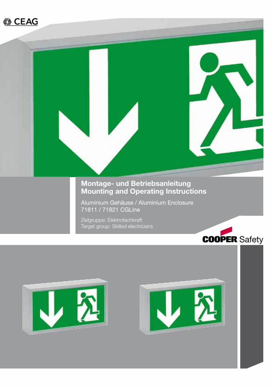
Inhaltsverzeichnis / Table of contents
1 Aufbau der Leuchte / Construction of the luminaire ............................. 3 1.1 SL/RZ 71811 CGLine .................................................................................. 3 1.2 RZ 71821 CGLine ........................................................................................ 4
2 Maßbilder / Dimensional Drawings ....................................................... 5 2.1 71811 CGLine Decken,- oder Wandmontage/Ceiling or wall mounting ..... 5 2.2 71821 CGLine Deckenmontage / Ceiling mounting .................................... 6 2.3 71821 CGLine Wandmontage / Wall mounting ........................................... 6 2.4 Pendel Set 0,5m / Pendulum Set 0,5m für / for 71821 CGLine .................. 7
3 Sicherheitshinweise .............................................................................. 9
4 Normenkonformität ............................................................................... 8
5 Technische Daten .................................................................................. 8 5.1 Verwendungsbereich / Kurzbeschreibung .................................................. 8
6 Installation / Inbetriebnahme ................................................................. 9 6.1 Montage ...................................................................................................... 9 6.2 Überwachungseinrichtung CGLine ............................................................. 9 Autarker Betrieb .............................................................................................................. 10
7 Wartung / Instandhaltung .................................................................... 10
8 Entsorgung / Recycling ....................................................................... 10
3 Safety instructions .............................................................................. 12
4 Conformity with standards .................................................................. 12
5 Technical data ..................................................................................... 12 5.1 Brief description / Scope of application .................................................... 12
6 Installation ........................................................................................... 13 6.1 Mounting ................................................................................................... 13 6.2 CGLine Monitoring Device ........................................................................ 13
7 Servicing ............................................................................................. 14
8 Recycling............................................................................................. 14
3
Montage und BetriebsanleitungAluminium Gehäuse 71811 / 71821 CGLine
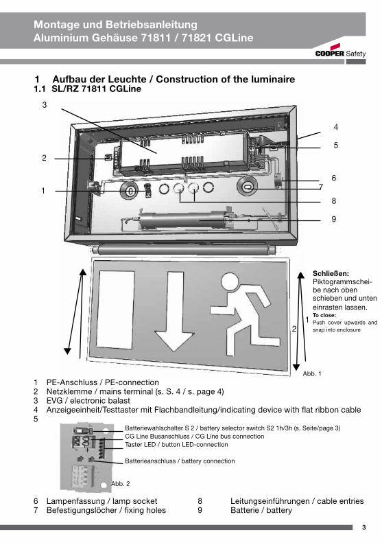
1 Aufbau der Leuchte / Construction of the luminaire1.1 SL/RZ 71811 CGLine
1
3
4
5
6 7 8
9
1 PE-Anschluss / PE-connection2 Netzklemme / mains terminal (s. S. 4 / s. page 4)3 EVG / electronic balast4 Anzeigeeinheit/Testtaster mit Flachbandleitung/indicating device with flat ribbon cable5
6 Lampenfassung / lamp socket 8 Leitungseinführungen / cable entries7 Befestigungslöcher / fixing holes 9 Batterie / battery
2
Batteriewahlschalter S 2 / battery selector switch S2 1h/3h (s. Seite/page 3)CG Line Busanschluss / CG Line bus connectionTaster LED / button LED-connection
Batterieanschluss / battery connection
Abb. 1
Abb. 2
- +
1 2
Schließen:Piktogrammschei-be nach oben schieben und unten einrasten lassen.To close:Push cover upwards and snap into enclosure
4
Montage und BetriebsanleitungAluminium Gehäuse 71811 / 71821 CGLine
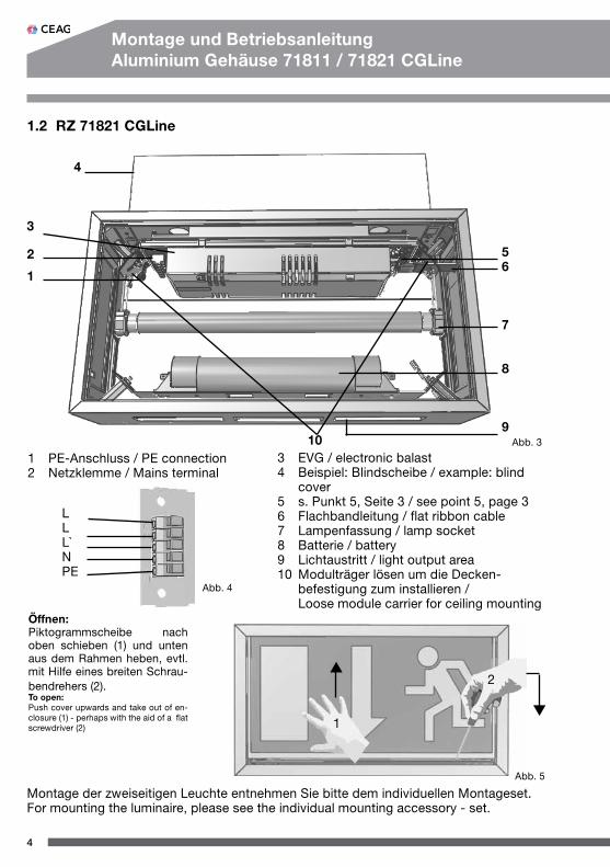
1.2 RZ 71821 CGLine
Montage der zweiseitigen Leuchte entnehmen Sie bitte dem individuellen Montageset.For mounting the luminaire, please see the individual mounting accessory - set.
1
2
3
4
56
7
8
9
1 PE-Anschluss / PE connection2 Netzklemme / Mains terminal
LLL`NPE
3 EVG / electronic balast4 Beispiel: Blindscheibe / example: blind cover5 s. Punkt 5, Seite 3 / see point 5, page 36 Flachbandleitung / flat ribbon cable7 Lampenfassung / lamp socket8 Batterie / battery9 Lichtaustritt / light output area10 Modulträger lösen um die Decken- befestigung zum installieren / Loose module carrier for ceiling mounting
Öffnen:Piktogrammscheibe nach oben schieben (1) und unten aus dem Rahmen heben, evtl. mit Hilfe eines breiten Schrau-bendrehers (2).To open:Push cover upwards and take out of en-closure (1) - perhaps with the aid of a flat screwdriver (2)
1
2
Abb. 3
Abb. 4
Abb. 5
10
5
Montage und BetriebsanleitungAluminium Gehäuse 71811 / 71821 CGLine
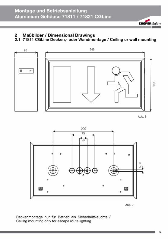
2 Maßbilder / Dimensional Drawings2.1 71811 CGLine Decken,- oder Wandmontage / Ceiling or wall mounting
Abb. 6
Abb. 7
Deckenmontage nur für Betrieb als Sicherheitsleuchte / Ceiling mounting only for escape route lighting
6
Montage und BetriebsanleitungAluminium Gehäuse 71811 / 71821 CGLine
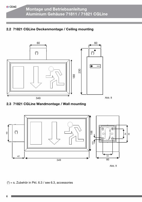
2.2 71821 CGLine Deckenmontage / Ceiling mounting
2.3 71821 CGLine Wandmontage / Wall mounting
Abb. 8
Abb. 9
(*)
(*)
(*)
(*) = s. Zubehör in Pkt. 6.3 / see 6.3, accessories
7
Montage und BetriebsanleitungAluminium Gehäuse 71811 / 71821 CGLine
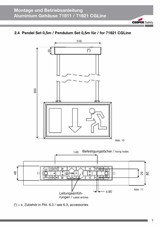
2.4 Pendel Set 0,5m / Pendulum Set 0,5m für / for 71821 CGLine
Abb. 10
Leitungseinfüh-rungen / cable entries
Befestigungslöcher / fixing holes
Abb. 11
(*) = s. Zubehör in Pkt. 6.3 / see 6.3, accessories
(*)
8
Montage und BetriebsanleitungAluminium Gehäuse 71811 / 71821 CGLine
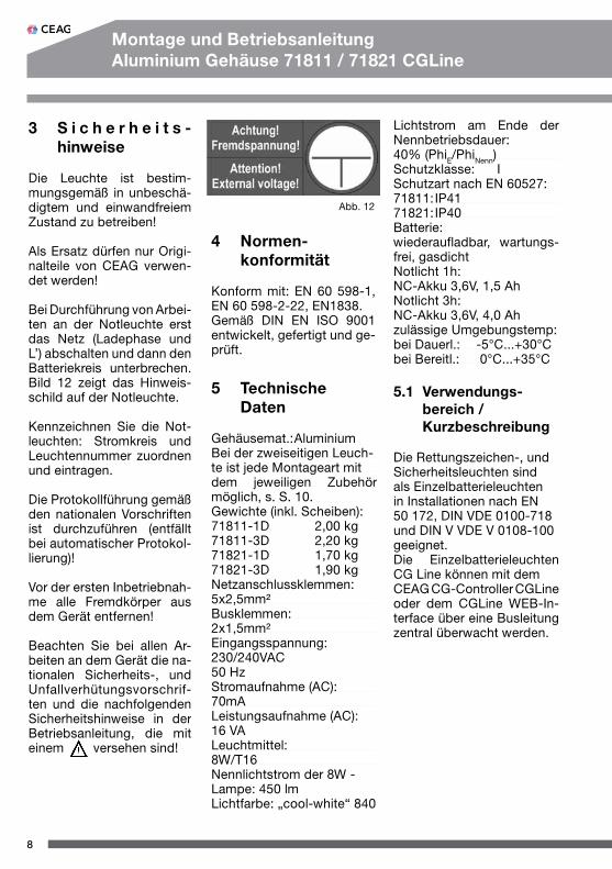
3 S i c h e r h e i t s - hinweise
Die Leuchte ist bestim-mungs gemäß in unbeschä-digtem und einwandfreiem Zustand zu betreiben!
Als Ersatz dürfen nur Origi-nalteile von CEAG verwen-det werden!
Bei Durchführung von Arbei-ten an der Notleuchte erst das Netz (Ladephase und L’) abschalten und dann den Batteriekreis unterbrechen. Bild 12 zeigt das Hinweis-schild auf der Notleuchte.
Kennzeichnen Sie die Not-leuchten: Stromkreis und Leuchtennummer zuordnen und eintragen.
Die Protokollführung gemäß den nationalen Vorschriften ist durchzuführen (entfällt bei automatischer Protokol-lierung)!
Vor der ersten Inbetriebnah-me alle Fremdkörper aus dem Gerät entfernen!
Beachten Sie bei allen Ar -beiten an dem Gerät die na-tionalen Sicherheits-, und Unfallverhütungsvorschrif-ten und die nachfolgenden Sicherheitshinweise in der Betriebsanleitung, die mit einem versehen sind!
Abb. 12
4 Normen- konformität
Konform mit: EN 60 598-1, EN 60 598-2-22, EN1838.Gemäß DIN EN ISO 9001 entwickelt, gefertigt und ge-prüft.
5 Technische Daten
Gehäusemat.: AluminiumBei der zweiseitigen Leuch-te ist jede Montageart mitdem jeweiligen Zubehör möglich, s. S. 10.Gewichte (inkl. Scheiben):71811-1D 2,00 kg71811-3D 2,20 kg71821-1D 1,70 kg71821-3D 1,90 kgNetzanschlussklemmen:5x2,5mm²Busklemmen:2x1,5mm²Eingangsspannung:230/240VAC50 HzStromaufnahme (AC):70mALeistungsaufnahme (AC):16 VALeuchtmittel:8W/T16Nennlichtstrom der 8W - Lampe: 450 lmLichtfarbe: „cool-white“ 840
Lichtstrom am Ende der Nennbetriebsdauer:40% (PhiE/PhiNenn) Schutzklasse: ISchutzart nach EN 60527:71811: IP4171821: IP40Batterie:wiederaufladbar, wartungs-frei, gasdichtNotlicht 1h:NC-Akku 3,6V, 1,5 AhNotlicht 3h:NC-Akku 3,6V, 4,0 Ahzulässige Umgebungstemp:bei Dauerl.: -5°C...+30°Cbei Bereitl.: 0°C...+35°C
5.1 Verwendungs- bereich / Kurzbeschreibung
Die Rettungszeichen-, und Sicherheitsleuchten sind als Einzelbatterieleuchten in Installationen nach EN 50 172, DIN VDE 0100-718 und DIN V VDE V 0108-100 geeignet. Die Einzelbatterieleuchten CG Line können mit demCEAG CG-Controller CGLine oder dem CGLine WEB-In-terface über eine Busleitung zentral überwacht werden.
9
Montage und BetriebsanleitungAluminium Gehäuse 71811 / 71821 CGLine
6 I n s t a l l a t i o n / Inbetriebnahme
Halten Sie die für das Errichten und Betrei-ben von elektrischen Betriebsmitteln gel-tenden Sicherheits-vorschriften und das Gerätesicherheitsge-setz, sowie die all-gemein anerkannten Regeln der Technik ein!
6.1 Montage
- Piktogrammscheibe ent-fernen (s. hierzu Abb. 5 / S. 4).- Leuchtmittel entfernen.
- Netzleitung einführen.
- Gehäuse an Befestigungs-löchern mit 2 Schrauben und 2 Dübeln an die Decke / Wand montieren.
Bei Pendel-, und Kettenbe-festigung werden diese lt. Zubehörset am Äußeren des Gehäuses befestigt.
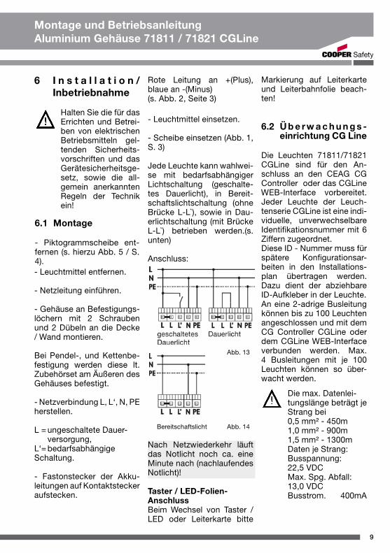
- Netzverbindung L, L‘, N, PE herstellen.
L = ungeschaltete Dauer- versorgung,L‘= bedarfsabhängige Schaltung.
- Fastonstecker der Akku-leitungen auf Kontaktstecker aufstecken.
Rote Leitung an +(Plus), blaue an -(Minus) (s. Abb. 2, Seite 3)
- Leuchtmittel einsetzen.
- Scheibe einsetzen (Abb. 1, S. 3)
Jede Leuchte kann wahlwei-se mit bedarfsabhängiger Lichtschaltung (geschalte-tes Dauerlicht), in Bereit-schaftslichtschaltung (ohne Brücke L-L`), sowie in Dau-erlichtschaltung (mit Brücke L-L`) betrieben werden.(s. unten)
Anschluss:
Abb. 13
Bereitschaftslicht Abb. 14
Nach Netzwiederkehr läuft das Notlicht noch ca. eine Minute nach (nachlaufendes Notlicht)!
Taster / LED-Folien-AnschlussBeim Wechsel von Taster / LED oder Leiterkarte bitte
Markierung auf Leiterkarte und Leiterbahnfolie beach-ten!
6.2 Ü b e r w a c h u n g s -einrichtung CG Line
Die Leuchten 71811/71821 CGLine sind für den An-schluss an den CEAG CG Controller oder das CGLine WEB-Interface vorbereitet. Jeder Leuchte der Leuch-tenserie CGLine ist eine indi-viduelle, unverwechselbare Identifikationsnummer mit 6 Ziffern zugeordnet.Diese ID - Nummer muss für spätere Konfigurationsar-beiten in den Installations-plan übertragen werden. Dazu dient der abziehbare ID-Aufkleber in der Leuchte.An eine 2-adrige Busleitung können bis zu 100 Leuchten angeschlossen und mit dem CG Controller CGLine oder dem CGLine WEB-Interface verbunden werden. Max. 4 Busleitungen mit je 100 Leuchten können so über-wacht werden.
Die max. Datenlei-tungslänge beträgt je Strang bei 0,5 mm² - 450m 1,0 mm² - 900m 1,5 mm² - 1300m Daten je Strang: Busspannung: 22,5 VDC Max. Spg. Abfall: 13,0 VDCBusstrom. 400mA
10
Montage und BetriebsanleitungAluminium Gehäuse 71811 / 71821 CGLine
7 Wartung / Instandhaltung
Halten Sie die für Instandhal-tung, Wartung und Prüfung von elektrischen Betriebs-mitteln geltenden nationalen Bestimmungen ein!
Für die Nachvollziehbarkeit der Batterie-Lebensdauer bitte das Inbetriebnahme-Datum in das auf der Batterie vorgesehene Feld eintragen!
8 Entsorgung / Recycling
Beachten Sie bei der Ent-sorgung defekter Geräte die gültigen nationalen Vor-schriften hinsichtlich Recy-cling und Entsorgung. Kunststoffmaterialien sind mit entsprechenden Sym-bolen gekennzeichnet.
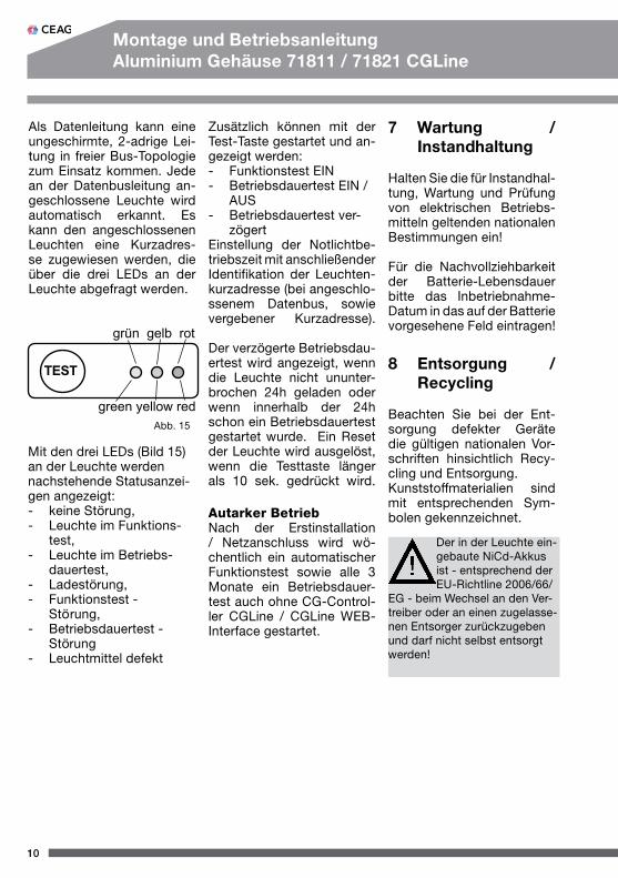
Als Datenleitung kann eine ungeschirmte, 2-adrige Lei-tung in freier Bus-Topologie zum Einsatz kommen. Jede an der Datenbusleitung an-geschlossene Leuchte wird automatisch erkannt. Es kann den angeschlossenen Leuchten eine Kurzadres-se zugewiesen werden, die über die drei LEDs an der Leuchte abgefragt werden.
TEST
grün gelb rot
green yellow red
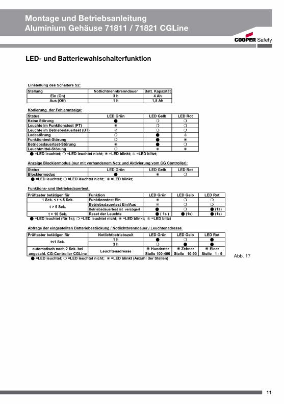
Mit den drei LEDs (Bild 15) an der Leuchte werden nachstehende Statusanzei-gen angezeigt: - keine Störung, - Leuchte im Funktions- test, - Leuchte im Betriebs- dauertest, - Ladestörung, - Funktionstest - Stö rung, - Betriebsdauertest - Störung - Leuchtmittel defekt
Autarker BetriebNach der Erstinstallation / Netzanschluss wird wö-chentlich ein automatischer Funktionstest sowie alle 3 Monate ein Betriebsdauer-test auch ohne CG-Control-ler CGLine / CGLine WEB-Interface gestartet.
Abb. 15
Zusätzlich können mit der Test-Taste gestartet und an-gezeigt werden:- Funktionstest EIN- Betriebsdauertest EIN / AUS- Betriebsdauertest ver- zögertEinstellung der Notlichtbe-triebszeit mit anschließender Identifikation der Leuchten-kurzadresse (bei angeschlo-ssenem Datenbus, sowie vergebener Kurzadresse). Der verzögerte Betriebsdau-ertest wird angezeigt, wenn die Leuchte nicht ununter-brochen 24h geladen oder wenn innerhalb der 24h schon ein Betriebsdauertest gestartet wurde. Ein Reset der Leuchte wird ausgelöst, wenn die Testtaste länger als 10 sek. gedrückt wird.
Der in der Leuchte ein-gebaute NiCd-Akkus ist - entsprechend der EU-Richtline 2006/66/
EG - beim Wechsel an den Ver-treiber oder an einen zugelasse-nen Entsorger zurückzugeben und darf nicht selbst entsorgt werden!
11
Montage und BetriebsanleitungAluminium Gehäuse 71811 / 71821 CGLine
LED- und Batteriewahlschalterfunktion
Abb. 17
12
Mounting and Operating InstructionsAluminium enclosure 71811 / 71821 CGLine
3 Safety instructions
The device shall only be used for its intended purpo-se and in undamaged and perfect condition!
Only genuine CEAG spare parts may be used for re-placement and repair.
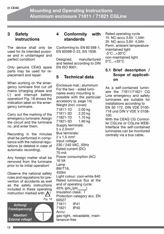
When working on the emer-gency luminaire first cut off mains (charging phase and L’) and interrupt battery operation! Fig. 18 shows the indication label on the emer-gency luminaire.
Carry out the marking of the emergency luminaire: Assign the circuit and the luminaire no. and enter them.
Recording in the minutes shall be performed in comp-liance with the national regu-lations (is deleted in case of automatic recording).
Any foreign matter shall be removed from the luminaire prior to its initial operation!
Observe the national safety rules and regulations for pre-vention of accidents as well as the safety instructions included in these operating instruction marked with !
Fig. 18
4 Conformity with standards
Conforming to: EN 60 598-1, EN 60598-2-22, EN 1838.
Designed, manufactured and tested according to DIN EN ISO 9001.
5 Technical data
Enclosure mat.: aluminiumFor the two - sided lumi-naires every mounting ispossible with the particular accessory (s. page 14).Weight (incl. cover):71811-1D 2.00 kg71811-3D 2.20 kg71821-1D 1.70 kg71821-3D 1.90 kgSupply terminals:5 x 2.5mm²Bus terminals:2 x 1.5 mm²Input voltage230 / 240 VAC, 50HzRated current (DC)70 mAPower consumption (AC)16 VALamp8W/T16, 450lmLight colour: cool-white 840Rated luminous flux at the end of operating cycle:40% (phiE/phinominate)Insulation class: IProtection category acc. EN6052771811 IP4171821 IP40Accu:gas-tight, reloadable, main-tenance-free
Rated operating cycle1h NC-accu 3,6V 1,5Ah3h NC-accu 3,6V 4,0AhPerm. ambient temperaturemaintained light-5°C...+30°Cnon-maintained light0°C...+35°C
5.1 Brief description / Scope of applicati-on
As a self-contained lumin-aire the 71811/71821 CG Line emergency and safety luminaires are suitable for installations according to EN 50 172, DIN VDE 0100-718 und DIN V VDE V 0108-100.With the CEAG CG Control-ler CGLine or CGLine WEB-Interface the self-contained luminaires can be monitored centrally via a bus cable.
13
Mounting and Operating InstructionsAluminium enclosure 71811 / 71821 CGLine
6 Installation
For the mounting and operation of electri-cal apparatus, the respective national safety regulations as well as the general rules of engineering will have to be obser-ved.
6.1 Mounting
Remove cover (see fig. 5, page 4).
Take off lamp.
Introduce mains cable.
Mount enclosure with 2 screws and 2 dowels through the fixing holes at the ceiling or wall.
For pendulum set mounting and chain suspension see manual of accessory set!
Connect mains to terminals L, L‘, N and PE.
L = unswitched permanent connectionL‘= switch on demand
Plug the faston plugs of the battery cables to the con-tact plugs on the conductor board - red wire to +(plus), blue wire to -(minus) (s. page 3, fig. 2).Insert lamp.
Insert cover (fig. 1, page 3).
Optionally, every luminaire can be operated with light switching (switched maintai-ned light), in non-maintained mode (without jumper) or in maintained mode (with jum-per). (see above)
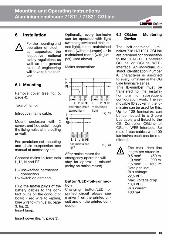
Mains connection:
Button/LED-foil-connec-tionChanging button/LED or printed circuit please see marker 1 on the printed cir-cuit and on the printed con-ductor.
6.2 CGLine Monitoring Device
The self-contained lumi-naires 71811/71821 CGLine are prepared for connection to the CEAG CG Controller CGLine or CGLine WEB-Interface. An individual, di-stinct identification number (6 characters) is assigned to every luminaire in the CG Line luminaire series.This ID-number must be transfered to the installa-tion plan for subsequent configuration work. The re-movable ID sticker in the lu-minaire can be used for this. Up to 100 luminaires can be connected to a 2-core bus cable and linked to the CG Controller CGLine or CGLine WEB-Interface. So max. 4 bus cables with 100 luminaires each can be mo-nitored.
The max. data line length per strand is0,5 mm² - 450 m1,0 mm² - 900 m1,5 mm² - 1300 mData per line:Bus voltage 22,5 VDC Max. voltage drop13,0 VDCBus current400 mA
Fig. 19
Fig. 20non maintainedlight
After mains return theemergency operation will stay for approx. 1 minute! (delay on mains return)
14
Mounting and Operating InstructionsAluminium enclosure 71811 / 71821 CGLine
7 Servicing
Observe the relevant natio-nal regulations which apply to the maintenance, ser-vicing and check of electrical apparatus!
To fathom batteries life ple-ase not the start-up date on the battery in the given data field!
8 Recycling
When a defective apparatus is disposed of, the respec-tive national regulations on waste disposal and recy-cling will have to be obser-ved. Plastic parts have been provided with respective symbols.
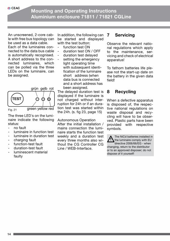
An unscreened, 2-core cab-le with free bus topology can be used as a data cable.Each of the luminaires con-nected to the data bus cable is automatically recognised. A short address to the con-nected luminaires, which can be polled via the three LEDs on the luminaire, can be assigned.
TEST
grün gelb rot
green yellow redFig. 21
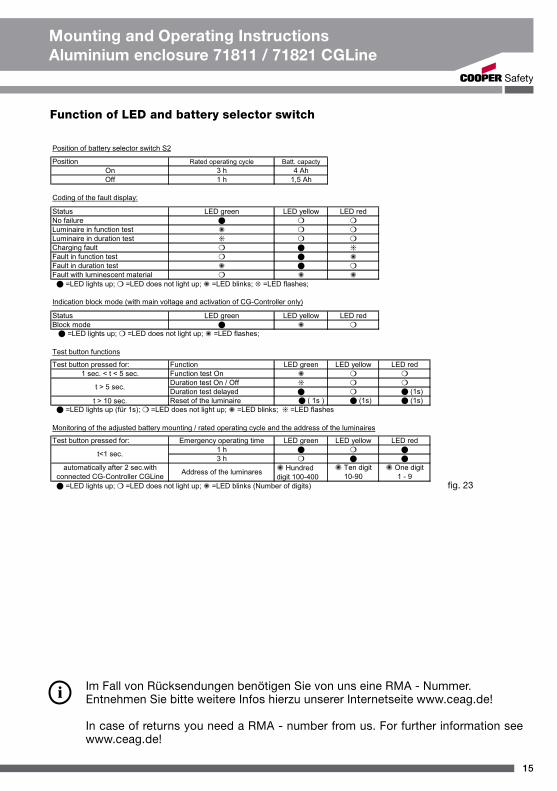
The three LED´s on the lumi-naire indicate the following status:- no fault- luminaire in function test- luminaire in duration test- charging fault- function-test fault- duration-test fault- luminescent material faulty
In addition, the following can be started and displayed with the test button:- function test ON- duration test ON / OFF- duration test delayed- setting the emergency light operating time with subsequent identi- fication of the luminaire short address (when data bus is connected and a short address has been assigned.The delayed duration test is displayed if the luminaire is not charged without inter-ruption for 24h or if an dura-tion test was started within the 24h. (s. fig 23, page 15)
Autonomous OperationAfter the initial installation / mains connection the lumi-naire starts the function test weekly and a duration test every three months also wi-thout the CG Controller CG Line / WEB-Interface.
The NiCd batteries installed in the luminaire comply with EU directive 2006/66/EG - when
changing, return to the distributor or to an approved disposer; do not dispose of it yourself!
15
Mounting and Operating InstructionsAluminium enclosure 71811 / 71821 CGLine
Im Fall von Rücksendungen benötigen Sie von uns eine RMA - Nummer. Entnehmen Sie bitte weitere Infos hierzu unserer Internetseite www.ceag.de!
In case of returns you need a RMA - number from us. For further information see www.ceag.de!
Function of LED and battery selector switch
fig. 23
400 71 351 471 (B)/XXX/12.11/WK
CEAG Notlichtsysteme GmbHSenator-Schwartz-Ring 26 59494 SoestGermany
Tel: +49 (0) 2921/69-870Fax: +49 (0) 2921/69-617Web: www.ceag.deEmail: [email protected]
Cooper SafetyJephson Court Tancred CloseRoyal Leamington SpaWarwickshire CV31 3RZUnited Kingdom
Tel: +44 (0) 1926 439200Fax: +44 (0) 1926 439240 Web: www.cooper-safety.comEmail: [email protected]