Multifunktionale Dreiphasenüberwachungsrelais CM-MPS
15
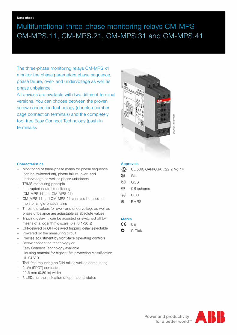
2CDC 251 066 V0011 Data sheet Multifunctional three-phase monitoring relays CM-MPS CM-MPS.11, CM-MPS.21, CM-MPS.31 and CM-MPS.41 The three-phase monitoring relays CM-MPS.x1 monitor the phase parameters phase sequence, phase failure, over- and undervoltage as well as phase unbalance. All devices are available with two different terminal versions. You can choose between the proven screw connection technology (double-chamber cage connection terminals) and the completely tool-free Easy Connect Technology (push-in terminals). Characteristics – Monitoring of three-phase mains for phase sequence (can be switched off), phase failure, over- and undervoltage as well as phase unbalance – TRMS measuring principle – Interrupted neutral monitoring (CM-MPS.11 and CM-MPS.21) – CM-MPS.11 and CM-MPS.21 can also be used to monitor single-phase mains – Threshold values for over- and undervoltage as well as phase unbalance are adjustable as absolute values – Tripping delay T v can be adjusted or switched off by means of a logarithmic scale (0 s; 0.1-30 s) – ON-delayed or OFF-delayed tripping delay selectable – Powered by the measuring circuit – Precise adjustment by front-face operating controls – Screw connection technology or Easy Connect Technology available – Housing material for highest fire protection classification UL 94 V-0 – Tool-free mounting on DIN rail as well as demounting – 2 c/o (SPDT) contacts – 22.5 mm (0.89 in) width – 3 LEDs for the indication of operational states Approvals A UL 508, CAN/CSA C22.2 No.14 C GL D GOST K CB scheme E CCC L RMRS Marks a CE b C-Tick
Transcript of Multifunktionale Dreiphasenüberwachungsrelais CM-MPS
2CD
C 2
51 0
66 V
0011
Data sheet
Multifunctional three-phase monitoring relays CM-MPSCM-MPS.11, CM-MPS.21, CM-MPS.31 and CM-MPS.41
The three-phase monitoring relays CM-MPS.x1
monitor the phase parameters phase sequence,
phase failure, over- and undervoltage as well as
phase unbalance.
All devices are available with two different terminal
versions. You can choose between the proven
screw connection technology (double-chamber
cage connection terminals) and the completely
tool-free Easy Connect Technology (push-in
terminals).
Characteristics – Monitoring of three-phase mains for phase sequence
(can be switched off), phase failure, over- and undervoltage as well as phase unbalance
– TRMS measuring principle – Interrupted neutral monitoring
(CM-MPS.11 and CM-MPS.21) – CM-MPS.11 and CM-MPS.21 can also be used to
monitor single-phase mains – Threshold values for over- and undervoltage as well as
phase unbalance are adjustable as absolute values – Tripping delay Tv can be adjusted or switched off by
means of a logarithmic scale (0 s; 0.1-30 s) – ON-delayed or OFF-delayed tripping delay selectable – Powered by the measuring circuit – Precise adjustment by front-face operating controls – Screw connection technology or
Easy Connect Technology available – Housing material for highest fire protection classification
UL 94 V-0 – Tool-free mounting on DIN rail as well as demounting – 2 c/o (SPDT) contacts – 22.5 mm (0.89 in) width – 3 LEDs for the indication of operational states
Approvals
A UL 508, CAN/CSA C22.2 No.14
C GL
D GOST
K CB scheme
E CCC
L RMRS
Marks
a CE
b C-Tick
2 - Multifunctional three-phase monitoring relays CM-MPS.x1 | Data sheet
Order data
Three-phase monitoring relays
Type Rated control supply voltage = measuring voltage
Interrupted neutral monitoring
Connection technology Order code
CM-MPS.11P 3 x 90-170 V AC yes Push-in terminals 1SVR 740 885 R1300
CM-MPS.11S yes Screw terminals 1SVR 730 885 R1300
CM-MPS.21P 3 x 180-280 V AC yes Push-in terminals 1SVR 740 885 R3300
CM-MPS.21S yes Screw terminals 1SVR 730 885 R3300
CM-MPS.31P 3 x 160-300 V AC no Push-in terminals 1SVR 740 884 R1300
CM-MPS.31S no Screw terminals 1SVR 730 884 R1300
CM-MPS.41P 3 x 300-500 V AC no Push-in terminals 1SVR 740 884 R3300
CM-MPS.41S no Screw terminals 1SVR 730 884 R3300
Accessories
Type Description Order code
ADP.01 Adapter for screw mounting 1SVR 430 029 R0100
MAR.12 Marker label for devices with DIP switches 1SVR 730 006 R0000
COV.11 Sealable transparent cover 1SVR 730 005 R0100

Data sheet | Multifunctional three-phase monitoring relays CM-MPS.x1 - 3
Connection technology
Maintenance free Easy Connect Technology with push-in terminals
Type designation CM-xxS.yyP
Approved screw connection technology with double-chamber cage connection terminals
Type designation CM-xxS.yyS
Push-in terminals
– Tool-free connection of rigid and flexible wires with wire end ferrule according to DIN 46228-1-A, DIN 46228-4-E Wire size: 2 x 0.5-1.5 mm², (2 x 20 - 16 AWG)
– Easy connection of flexible wires without wire end ferrule by opening the terminals
– No retightening necessary – One operation lever for opening both connection
terminals – For triggering the lever and disconnecting of wires
you can use the same tool (Screwdriver according to DIN ISO 2380-1 Form A 0.8 x 4 mm (0.0315 x 0.157 in), DIN ISO 8764-1 PZ1 ø 4.5 mm (0.177 in))
– Constant spring force on terminal point independent of the applied wire type, wire size or ambient conditions (e. g. vibrations or temperature changes)
– Opening for testing the electrical contacting – Gas-tight
Double-chamber cage connection terminals
– Terminal spaces for different wire sizes: fine-strand with/without wire end ferrule: 1 x 0.5-2.5 mm² (2 x 20 - 14 AWG), 2 x 0.5-1.5 mm² (2 x 20 - 16 AWG) rigid: 1 x 0.5-4 mm² (1 x 20 - 12 AWG), 2 x 0.5-2.5 mm² (2 x 20 - 14 AWG)
– One screw for opening and closing of both cages – Pozidrive screws for pan- or crosshead screwdrivers
according to DIN ISO 2380-1 Form A 0.8 x 4 mm (0.0315 x 0.157 in), DIN ISO 8764-1 PZ1 ø 4.5 mm (0.177 in)
Both the Easy Connect Technology with push-in terminals and screw connection technology with double-chamber cage connection terminals have the same connection geometry as well as terminal position.
2CD
C 2
53 0
25 F
0011
2CD
C 2
53 0
26 F
0011

4 - Multifunctional three-phase monitoring relays CM-MPS.x1 | Data sheet
Functions
Operating controls
2CD
C 2
51 0
66 V
0011
1 Adjustment of the hysteresis >U for overvoltage
2 Adjustment of the threshold value <U for undervoltage
3 Indication of operational states
R/T: red LED – Relay status / timing
F1: yellow LED – Fault message
F2: yellow LED – Fault message
4 Adjustment of the threshold value Asym. for phase unbalance
5 Adjustment of the tripping delay Tv
6 DIP switches (see DIP switch functions)
Application
The three-phase monitoring relays CM-MPS.x1 are designed for use in three-phase mains for monitoring the phase parameters phase sequence, phase failure, over- and undervoltage as well as phase unbalance. The CM-MPS.11 and CM-MPS.21 also monitor the neutral for interruption and are suitable for monitoring single-phase mains.
The CM-MPS.x1 provide an adjustable tripping delay and work and according to the closed-circuit principle.
Operating mode
The CM-MPS.x1 have 2 c/o (SPDT) contacts and are available for 3-wire AC systems (CM-MPS.31, CM-MPS.41) and 4-wire AC systems (CM-MPS.11, CM-MPS.21).
The units are adjusted with front-face operating controls. The selection of ON- A or OFF- B delay and phase sequence monitoring activated k or phase sequence monitoring deactivated l is made with DIP switches. Potentiometers, with direct reading scale, allow the adjustment of the threshold values for overvoltage (>U), undervoltage (<U), phase unbalance (Asym %) and the tripping delay Tv. The tripping delay Tv is adjustable over a range of instantaneous to a 30 s delay. Timing is displayed by a flashing yellow LED labelled R/T.
For monitoring single-phase mains, all three external conductors (L1, L2, L3) have to be jumpered and connected as one single conductor. Phase sequence monitoring has to be deactivated and the threshold value for phase unbalance has to be set to the maximum (25 %).
1
3
2
4
5
6
Data sheet | Multifunctional three-phase monitoring relays CM-MPS.x1 - 5
Adjustment potentiometer
Threshold values
By means of three separate potentiometers with direct reading scales, the threshold values for over- and undervoltage as well as for phase unbalance can be adjusted within the measuring range.
Measuring range for overvoltage Measuring range for undervoltage Measuring range for phase unbalance
CM-MPS.11 3 x 120-170 V AC 3 x 90-130 V AC
2-25 % of average of phase voltagesCM-MPS.21 3 x 240-280 V AC 3 x 180-220 V AC
CM-MPS.31 3 x 220-300 V AC 3 x 160-230 V AC
CM-MPS.41 3 x 420-500 V AC 3 x 300-380 V AC
Tripping delay Tv
The tripping delay Tv can be adjusted within a range of 0.1 to 30 s by means of a potentiometer with logarithmic scale. By turning to the left stop, the tripping delay can be switched off.
Indication of operational states
LEDs, status information and fault messages
Operational state R/T: LED yellow F1: LED red F2: LED red
Control supply voltage applied,
output relay energizedV - -
Tripping delay Tv active W - -
Phase failure - V W
Phase sequence - W alternating
Overvoltage - V -
Undervoltage - - V
Phase unbalance - V V
Interruption of the neutral - V W
Adjustment error 1) W W W
1) Overlapping of the threshold values: The threshold value for overvoltage is set to a smaller value than the threshold value for undervoltage.
Function descriptions / diagrams
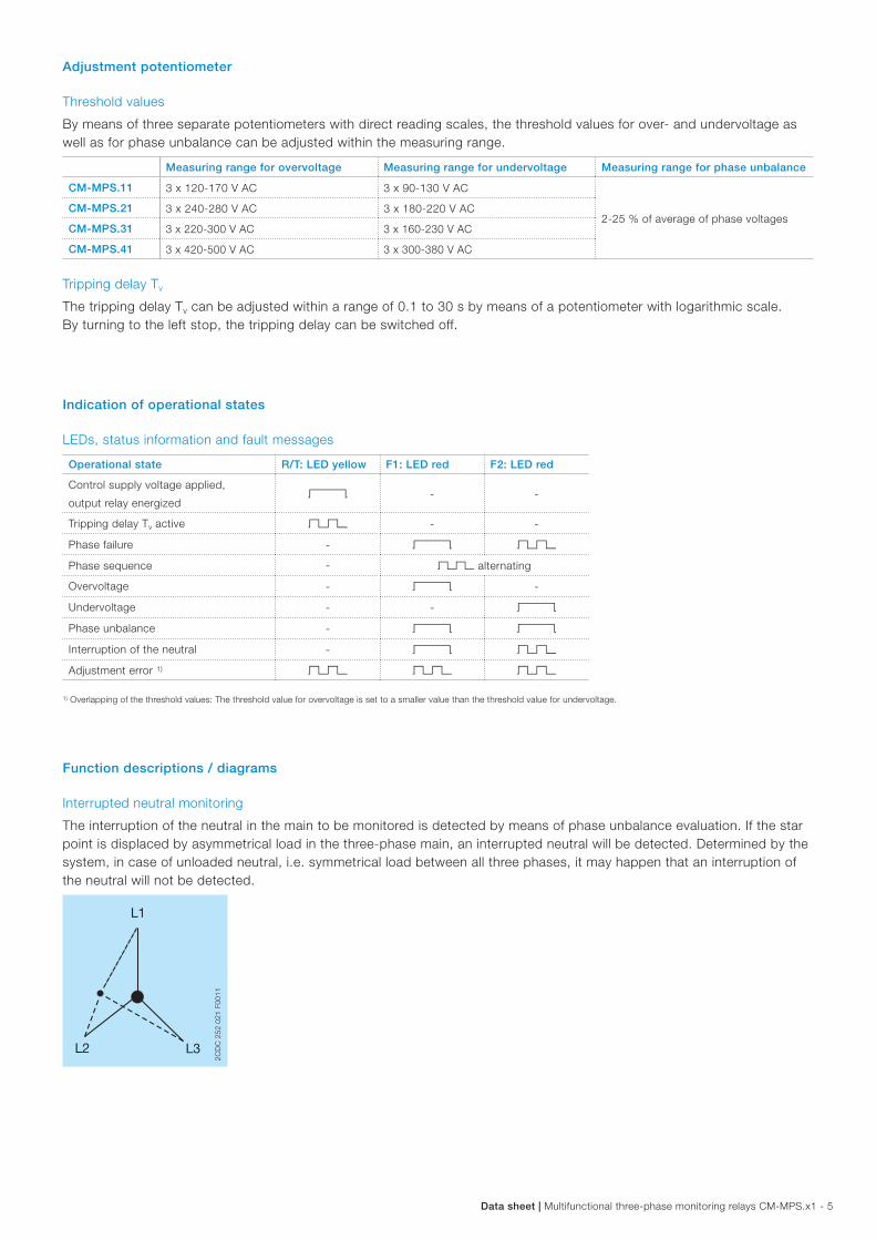
Interrupted neutral monitoring
The interruption of the neutral in the main to be monitored is detected by means of phase unbalance evaluation. If the star point is displaced by asymmetrical load in the three-phase main, an interrupted neutral will be detected. Determined by the system, in case of unloaded neutral, i.e. symmetrical load between all three phases, it may happen that an interruption of the neutral will not be detected.
2CD
C 2
52 0
21 F
0011

6 - Multifunctional three-phase monitoring relays CM-MPS.x1 | Data sheet
Phase sequence and phase failure monitoring
Applying control supply voltage begins the fixed start-up delay Ts. When Ts is complete and all phases are present with correct voltage, the output relays energize and the yellow LED R/T is on.
Phase sequence monitoring:
If phase sequence monitoring is activated (DIP switch 2 = OFF), the output relays de-energize as soon as a phase sequence error occurs. The fault is displayed by alternated flashing of the LEDs F1 and F2. The output relays re-energize automatically as soon as the phase sequence is correct again.
If phase sequence monitoring is deactivated (DIP switch 2 = ON), a phase sequence error will not cause tripping of the relays. The output relays do not change state and the LEDs F1 and F2 don‘t flash.
Phase failure monitoring:
The output relays de-energize instantaneously if a phase failure occurs. The fault is indicated by lightning of LED F1 and flashing of LED F2. The output relays re-energize automatically as soon as the voltage returns to the tolerance range.
25-2625-28
L1, L2, L3
15-1615-18
L1, L2, L3 L1, L2, L3 L1, L2, L3 L1, L2, L3L1, L3, L2 L1, L2 L1
L3 L2, L3Ts
2CD
C 2
52 0
94 F
0207
F1: red LED
F2: red LED
R/T: yellow LED
Measured value
Ts = start-up delay fixed 200 ms
2CD
C 2
52 0
94 F
0207

Data sheet | Multifunctional three-phase monitoring relays CM-MPS.x1 - 7
Over- and undervoltage monitoring
Applying control supply voltage begins the fixed start-up delay Ts. When Ts is complete and all phases are present with correct voltage and with correct phase sequence, the output relays energize and the yellow LED R/T is on.
Type of tripping delay = ON-delay A
If the voltage to be monitored exceeds or falls below the set threshold value, the output relays de-energize after the set tripping delay Tv is complete. The LED R/T flashes during timing and turns off as soon as the output relays de-energize.
The output relays re-energize automatically as soon as the voltage returns to the tolerance range, taking into account a fixed hysteresis of 5 %. The LED R/T is on.
L1, L2, L3
15-1615-18
> U> U - 5 %
< U + 5 %< U
Ts Tv Tv<Tv
25-2625-28
2CD
C 2
52 0
90 F
0207
F1: red LED
F2: red LED
R/T: yellow LED
Measured value
Ts = start-up delay fixed 200 msTv = adjustable tripping delay
2CD
C 2
52 0
90 F
0207
Type of tripping delay = OFF-delay B
If the voltage to be monitored exceeds or falls below the set threshold value, the output relays de-energize instantaneously and the LED R/T turns off.
As soon as the voltage returns to the tolerance range, taking into account a fixed hysteresis of 5 %, the output relays re-energize automatically after the set tripping delay Tv is complete. The LED R/T flashes during timing and turns steady when timing is complete.
25-2625-28
L1, L2, L3
15-1615-18
> U> U - 5 %
< U + 5 %< U
Ts <Tv<TvTv
2CD
C 2
52 0
91 F
0207
F1: red LED
F2: red LED
R/T: yellow LED
Measured value
Ts = start-up delay fixed 200 msTv = adjustable tripping delay
2CD
C 2
52 0
91 F
0207

8 - Multifunctional three-phase monitoring relays CM-MPS.x1 | Data sheet
Phase unbalance monitoring
Applying control supply voltage begins the fixed start-up delay Ts. When Ts is complete and all phases are present with correct voltage and with correct phase sequence, the output relays energize and the yellow LED R/T is on.
Type of tripping delay = ON-delay A
If the voltage to be monitored exceeds or falls below the set phase unbalance threshold value, the output relays de-energize after the set tripping delay Tv is complete. The LED R/T flashes during timing and turns off as soon as the output relays de-energize.
The output relays re-energize automatically as soon as the voltage returns to the tolerance range, taking into account a fixed hysteresis of 20 %. The LED R/T is on.
L1, L2, L3
15-1615-18
L1, L2, L3 L1, L2
L3
Ts Tv Tv<Tv
25-2625-28
2CD
C 2
52 0
92 F
0207
F1: red LED
F2: red LED
R/T: yellow LED
Measured value
UnbalanceUnbalance - Hysteresis
Unbalance + HysteresisUnbalance
Ts = start-up delay fixed 200 msTv = adjustable tripping delay
2CD
C 2
52 0
92 F
0207
Type of tripping delay = OFF-delay B
If the voltage to be monitored exceeds or falls below the set phase unbalance threshold value, the output relays de-energize instantaneously and the LED R/T turns off.
As soon as the voltage returns to the tolerance range, taking into account a fixed hysteresis of 20 %, the output relays re-energize automatically after the set tripping delay Tv is complete. The LED R/T flashes during timing and turns steady when timing is complete.
25-2625-28
L1, L2, L3
15-1615-18
Ts <Tv<TvTv
L1, L2, L3 L1, L2
L3
2CD
C 2
52 0
93 F
0207
F1: red LED
F2: red LED
R/T: yellow LED
Measured value
UnbalanceUnbalance - Hysteresis
Unbalance + HysteresisUnbalance
Ts = start-up delay fixed 200 msTv = adjustable tripping delay
2CD
C 2
52 0
93 F
0207

Data sheet | Multifunctional three-phase monitoring relays CM-MPS.x1 - 9
Electrical connection
L1N
L2
28252618
L3
L3 15
16 18 26 28
25L2
N
L1
16 152C
DC
252
036
F00
08
L1 L2
28252618
L3
L3 15
16 18 26 28
25L2L1
16 15
2CD
C 2
52 0
37 F
0008
L1, L2, L3, (N) Control supply voltage = measuring
voltage
15-16/18
25-26/28
Output contacts - closed-circuit principle
Connection diagram CM-MPS.11 and CM-MPS.21
Connection diagram CM-MPS.31 and CM-MPS.41
DIP switches
Position 1 2
ON
OFF
2CD
C 2
52 0
40 F
0008
1 Timing function ON ON-delayed In case of a fault, the de-energizing of the output relays and the respective fault message are suppressed for the adjusted tripping delay Tv.
OFF OFF-delayed In case of a fault, the output relays de-energize instantaneously and a fault message is displayed and stored for the duration of the adjusted tripping delay Tv. Thereby, also momentary undervoltage conditions are recognized.
2 Phase sequence monitoring ON deactivated Phase sequence errors will not cause tripping of the relays.
OFF activated The output relays de-energize as soon as a phase sequence error occurs. The output relays re-energize automatically as soon as the phase sequence is correct again.
10 - Multifunctional three-phase monitoring relays CM-MPS.x1 | Data sheet
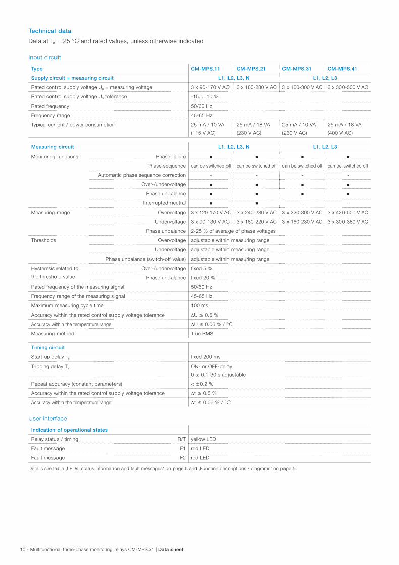
Technical data
Data at Ta = 25 °C and rated values, unless otherwise indicated
Input circuit
Type CM-MPS.11 CM-MPS.21 CM-MPS.31 CM-MPS.41
Supply circuit = measuring circuit L1, L2, L3, N L1, L2, L3
Rated control supply voltage Us = measuring voltage 3 x 90-170 V AC 3 x 180-280 V AC 3 x 160-300 V AC 3 x 300-500 V AC
Rated control supply voltage Us tolerance -15...+10 %
Rated frequency 50/60 Hz
Frequency range 45-65 Hz
Typical current / power consumption 25 mA / 10 VA
(115 V AC)
25 mA / 18 VA
(230 V AC)
25 mA / 10 VA
(230 V AC)
25 mA / 18 VA
(400 V AC)
Measuring circuit L1, L2, L3, N L1, L2, L3
Monitoring functions Phase failure J J J J
Phase sequence can be switched off can be switched off can be switched off can be switched off
Automatic phase sequence correction - - - -
Over-/undervoltage J J J J
Phase unbalance J J J J
Interrupted neutral J J - -
Measuring range Overvoltage 3 x 120-170 V AC 3 x 240-280 V AC 3 x 220-300 V AC 3 x 420-500 V AC
Undervoltage 3 x 90-130 V AC 3 x 180-220 V AC 3 x 160-230 V AC 3 x 300-380 V AC
Phase unbalance 2-25 % of average of phase voltages
Thresholds Overvoltage adjustable within measuring range
Undervoltage adjustable within measuring range
Phase unbalance (switch-off value) adjustable within measuring range
Hysteresis related to
the threshold value
Over-/undervoltage fixed 5 %
Phase unbalance fixed 20 %
Rated frequency of the measuring signal 50/60 Hz
Frequency range of the measuring signal 45-65 Hz
Maximum measuring cycle time 100 ms
Accuracy within the rated control supply voltage tolerance DU 0.5 %
Accuracy within the temperature range DU 0.06 % / °C
Measuring method True RMS
Timing circuit
Start-up delay Ts fixed 200 ms
Tripping delay Tv ON- or OFF-delay
0 s; 0.1-30 s adjustable
Repeat accuracy (constant parameters) < w0.2 %
Accuracy within the rated control supply voltage tolerance Dt 0.5 %
Accuracy within the temperature range Dt 0.06 % / °C
User interface
Indication of operational states
Relay status / timing R/T yellow LED
Fault message F1 red LED
Fault message F2 red LED
Details see table ‚LEDs, status information and fault messages‘ on page 5 and ‚Function descriptions / diagrams‘ on page 5.
Data sheet | Multifunctional three-phase monitoring relays CM-MPS.x1 - 11
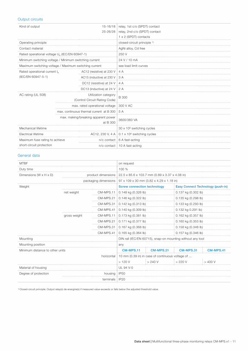
Output circuits
Kind of output 15-16/18
25-26/28
relay, 1st c/o (SPDT) contact
relay, 2nd c/o (SPDT) contact
1 x 2 (SPDT) contacts
Operating principle closed-circuit principle 1)
Contact material AgNi alloy, Cd free
Rated operational voltage Ue (IEC/EN 60947-1) 250 V
Minimum switching voltage / Minimum switching current 24 V / 10 mA
Maximum switching voltage / Maximum switching current see load limit curves
Rated operational current Ie
(IEC/EN 60947-5-1)
AC12 (resistive) at 230 V 4 A
AC15 (inductive) at 230 V 3 A
DC12 (resistive) at 24 V 4 A
DC13 (inductive) at 24 V 2 A
AC rating (UL 508) Utilization category
(Control Circuit Rating Code)B 300
max. rated operational voltage 300 V AC
max. continuous thermal current at B 300 5 A
max. making/breaking apparent power
at B 3003600/360 VA
Mechanical lifetime 30 x 106 switching cycles
Electrical lifetime AC12, 230 V, 4 A 0.1 x 10⁶ switching cycles
Maximum fuse rating to achieve
short-circuit protection
n/c contact 6 A fast-acting
n/o contact 10 A fast-acting
General data
MTBF on request
Duty time 100 %
Dimensions (W x H x D) product dimensions 22.5 x 85.6 x 103.7 mm (0.89 x 3.37 x 4.08 in)
packaging dimensions 97 x 109 x 30 mm (3.82 x 4.29 x 1.18 in)
Weight Screw connection technology Easy Connect Technology (push-in)
net weight CM-MPS.11 0.148 kg (0.326 lb) 0.137 kg (0.302 lb)
CM-MPS.21 0.146 kg (0.322 lb) 0.135 kg (0.298 lb)
CM-MPS.31 0.142 kg (0.313 lb) 0.133 kg (0.293 lb)
CM-MPS.41 0.140 kg (0.309 lb) 0.132 kg 0.291 lb)
gross weight CM-MPS.11 0.173 kg (0.381 lb) 0.162 kg (0.357 lb)
CM-MPS.21 0.171 kg (0.377 lb) 0.160 kg (0.353 lb)
CM-MPS.31 0.167 kg (0.368 lb) 0.158 kg (0.348 lb)
CM-MPS.41 0.165 kg (0.364 lb) 0.157 kg (0.346 lb)
Mounting DIN rail (IEC/EN 60715), snap-on mounting without any tool
Mounting position any
Minimum distance to other units
horizontal
CM-MPS.11 CM-MPS.21 CM-MPS.31 CM-MPS.41
10 mm (0.39 in) in case of continuous voltage of ...
> 120 V > 240 V > 220 V > 400 V
Material of housing UL 94 V-0
Degree of protection housing IP50
terminals IP20
1) Closed-circuit principle: Output relay(s) de-energize(s) if measured value exceeds or falls below the adjusted threshold value.

12 - Multifunctional three-phase monitoring relays CM-MPS.x1 | Data sheet
Electrical connection
Screw connection technology
Easy Connect Technology (push-in)
Wire size fine-strand with(out)
wire end ferrule
1 x 0.5-2.5 mm²
(1 x 20-14 AWG)
2 x 0.5-1.5 mm²
(2 x 20-16 AWG)
2 x 0.5-1.5 mm²
(2 x 20-16 AWG)
rigid 1 x 0.5-4 mm²
(1 x 20-12 AWG)
2 x 0.5-2.5 mm²
(2 x 20-14 AWG)
2 x 0.5-1.5 mm²
(2 x 20-16 AWG)
Stripping length 8 mm (0.32 in)
Tightening torque 0.6 - 0.8 Nm
(5.31 - 7.08 lb.in)
-
Environmental data
Ambient temperature ranges operation -25...+60 °C
storage -40...+85 °C
Damp heat, cyclic (IEC/EN 60068-2-30) 55 °C, 6 cycles
Climatic category 3K3
Vibration, sinusoidal (IEC/EN 60255-21-1) Class 2
Shock (IEC/EN 60255-21-2) Class 2
Isolation data
Type CM-MPS.11 CM-MPS.21 CM-MPS.31 CM-MPS.41
Rated insulation
voltage Ui
input circuit / output circuit 600 V
output circuit 1 / output circuit 2 300 V
Rated impulse withstand voltage Uimp
(IEC/EN 60664)
input circuit 6 kV, 1.2/50 µs
output circuit 4 kV, 1.2/50 µs
Test voltage between all isolated circuits (routine test) 2.5 kV, 50 Hz, 1 s
Basic insulation input circuit / output circuit 600 V
Protective separation
(IEC/EN 61140, EN 50178)
input circuit /
output circuityes -
Pollution degree (IEC/EN 60664, IEC/EN 60255-5) 3
Overvoltage category (IEC/EN 60664, IEC/EN 60255-5) III
Standards
Product standard IEC/EN 60255-6, EN 50178
Low Voltage Directive 2006/95/EC
EMC directive 2004/108/EC
RoHS directive 2002/95/EC
Data sheet | Multifunctional three-phase monitoring relays CM-MPS.x1 - 13
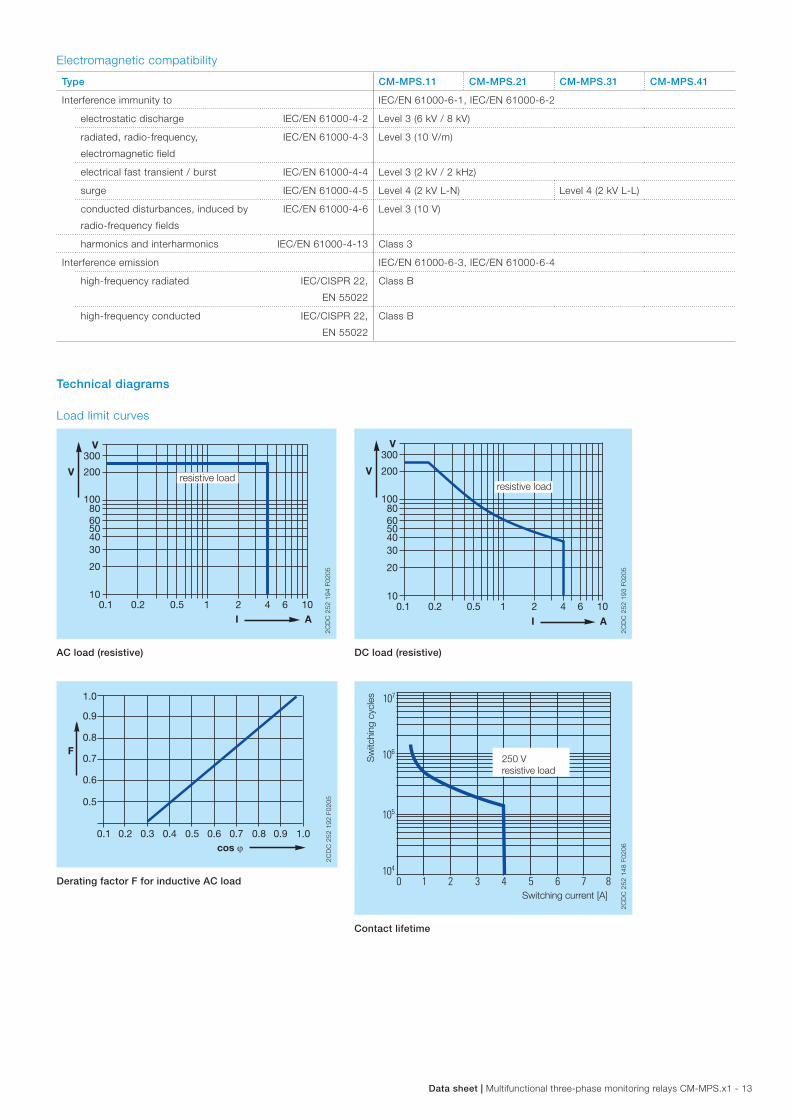
Electromagnetic compatibility
Type CM-MPS.11 CM-MPS.21 CM-MPS.31 CM-MPS.41
Interference immunity to IEC/EN 61000-6-1, IEC/EN 61000-6-2
electrostatic discharge IEC/EN 61000-4-2 Level 3 (6 kV / 8 kV)
radiated, radio-frequency,
electromagnetic field
IEC/EN 61000-4-3 Level 3 (10 V/m)
electrical fast transient / burst IEC/EN 61000-4-4 Level 3 (2 kV / 2 kHz)
surge IEC/EN 61000-4-5 Level 4 (2 kV L-N) Level 4 (2 kV L-L)
conducted disturbances, induced by
radio-frequency fields
IEC/EN 61000-4-6 Level 3 (10 V)
harmonics and interharmonics IEC/EN 61000-4-13 Class 3
Interference emission IEC/EN 61000-6-3, IEC/EN 61000-6-4
high-frequency radiated IEC/CISPR 22,
EN 55022
Class B
high-frequency conducted IEC/CISPR 22,
EN 55022
Class B
Technical diagrams
Load limit curves
300
200
1008060504030
20
101 2 4 6 10
I A
V
V
0.1 0.2 0.5
resistive load
2CD
C 2
52 1
94 F
0205
AC load (resistive)
300
200
100 80 60 50 40 30
20
10 1 2 4 6 10
I A
V
V
0.1 0.2 0.5
resistive load
2CD
C 2
52 1
93 F
0205
DC load (resistive)
cos ϕ
F
0.5
0.1 0.2 0.3 0.4 0.5 0.6 0.7 0.8 0.9 1.0
0.6
0.7
0.8
0.9
1.0
2CD
C 2
52 1
92 F
0205
Derating factor F for inductive AC load
Switching current [A]
Sw
itchi
ng c
ycle
s
250 Vresistive load
2CD
C 2
52 1
48 F
0206
Contact lifetime

14 - Multifunctional three-phase monitoring relays CM-MPS.x1 | Data sheet
Dimensions
in mm and inches
113.4 4.47”
22.5 0.89”
85.6
3.
37”
103.7 4.08”
105.9 4.17”
2CD
C 2
52 0
09 F
0011
Accessories
in mm and inches
22.5 0.89”
68
2.68
”
110.5 4.31”
8 0.32”
4.8 0.19”
front to back
2CD
C 2
52 0
10 F
0011
6.5 62.5
60
1011
.5
20
0.25
6”
2.461”
2.362”
70 2.756”
0.39
4”
0.78
7”
0.45
3”
2CD
C 2
52 0
08 F
0010
19.94T22 7.
850.
309”
0.783”
22.20.874”
2CD
C 2
52 0
20 F
0011
ADP.01 - Adapter for screw mounting MAR.12 - Marker label for devices with DIP switches
COV.11 - Sealable transparent cover
Further documentation
Document title Document type Document number
Electronic products and relays Technical catalogue 2CDC 110 004 C02xx
CM-MPS.11, CM-MPS.21, CM-MPS.31,
CM-MPS.41
Instruction manual 1SVC 730 520 M0000
You can find the documentation on the internet at www.abb.com/lowvoltage -> Control Products -> Electronic Relays and Controls -> Three Phase Monitors.

ABB STOTZ-KONTAKT GmbHP. O. Box 10 16 8069006 Heidelberg, GermanyPhone: +49 (0) 6221 7 01-0Fax: +49 (0) 6221 7 01-13 25E-mail: [email protected]
You can find the address of your local sales organisation on the ABB home pagehttp://www.abb.com/contacts -> Low Voltage Products and Systems
Contact us
Note:We reserve the right to make technical changes or modify the contents of this document without prior notice. With regard to purchase orders, the agreed particulars shall prevail. ABB AG does not accept any responsibility whatsoever for potential errors or possible lack of information in this document.
We reserve all rights in this document and in the subject matter and illustrations contained therein. Any reproduction, disclosure to third parties or utilization of its contents – in whole or in parts – is forbidden without prior written consent of ABB AG.
Copyright© 2012 ABB All rights reserved
Do
cum
ent
num
ber
2C
DC
112
175
D02
01 (1
1.20
12)