Multifunktionales Sicherheitsmodul UG 6970, SAFEMASTER C · 3 UG 6970 / 05.12.17 de / 947...
40
1 UG 6970 / 05.12.17 de / 947 SAFEMASTER C Multifunktionales Sicherheits- modul UG 6970 0266691 Datenblatt / Betriebsanleitung DEUTSCH E. DOLD & SÖHNE KG Postfach 1251 • 78114 Furtwangen • Deutschland Telefon +49 7723 6540 • Fax +49 7723 654356 [email protected] • www.dold.com Original DE EN FR
Transcript of Multifunktionales Sicherheitsmodul UG 6970, SAFEMASTER C · 3 UG 6970 / 05.12.17 de / 947...
1 UG 6970 / 05.12.17 de / 947
SAFEMASTER C Multifunktionales Sicherheits- modul UG 6970
0266691
Datenblatt / Betriebsanleitung DEUTSCH
E. DOLD & SÖHNE KGPostfach 1251 • 78114 Furtwangen • DeutschlandTelefon +49 7723 6540 • Fax +49 7723 [email protected] • www.dold.com
Original
DE
EN
FR
2 UG 6970 / 05.12.17 de / 947
Inhaltsverzeichnis
Symbol- und Hinweiserklärung ..........................................................................................................................................3
Allgemeine Hinweise ........................................................................................................................................................3
Bestimmungsgemäße Verwendung ...................................................................................................................................3
Sicherheitshinweise ...........................................................................................................................................................3
Produktbeschreibung .........................................................................................................................................................5
Schaltbild ...........................................................................................................................................................................5
Anschlussklemmen ............................................................................................................................................................5
Zulassungen und Kennzeichen .........................................................................................................................................5
Anwendungen ....................................................................................................................................................................5
Geräteanzeigen .................................................................................................................................................................5
Funktionsdiagramm ...........................................................................................................................................................6
Blinkcodes zur Fehlermeldung ..........................................................................................................................................6
Blockschaltbild ...................................................................................................................................................................6
Hinweise ............................................................................................................................................................................7
Bedienelemente .................................................................................................................................................................7
Technische Daten ..............................................................................................................................................................7
Technische Daten ..............................................................................................................................................................8
UL-Daten ...........................................................................................................................................................................8
Standardtype .....................................................................................................................................................................8
Bestellbeispiel ....................................................................................................................................................................9
Vorgehen bei Störungen ....................................................................................................................................................9
Wartung und Instandsetzung .............................................................................................................................................9
Kennlinien ..........................................................................................................................................................................9
Anwendungsbeispiel mit Sicherheitsfunktion ..................................................................................................................10
Anwendungsbeispiel mit Sicherheitsfunktion 1 ...............................................................................................................11
Anwendungsbeispiel mit Sicherheitsfunktion 2 ...............................................................................................................11
Beschriftung und Anschlüsse ..........................................................................................................................................37
Maßbild (Maße in mm) ....................................................................................................................................................38
Montage / Demontage der PS / PC / PT-Klemmenblöcke ...............................................................................................38
Sicherheitstechnische Kenndaten ...................................................................................................................................39
EG-Konformitätserklärung ...............................................................................................................................................40
3 UG 6970 / 05.12.17 de / 947
Sicherheitshinweise
WARNUNG
Gefahr durch elektrischen Schlag! Lebensgefahr oder schwere Verletzungsgefahr.• Stellen Sie sicher, dass Anlage und Gerät während der elektrischen Installation in spannungsfreiem Zustand sind und bleiben.• Das Gerät darf nur für die in der mitgeltenden Betriebsanleitung / Daten-
blatt vorgesehenen Einsatzfälle verwendet werden. Die Hinweise in den zugehörigen Dokumentationen müssen beachtet werden. Die zulässigen Umgebungsbedingungen müssen eingehalten werden.
• Der Berührungsschutz der angeschlossenen Elemente und die Isolation der Zuleitungen sind für die höchste am Gerät anliegende Spannung auszulegen.
• Beachten Sie die VDE- sowie die örtlichen Vorschriften, insbesondere hinsichtlich Schutzmaßnahmen.
WARNUNG
Brandgefahr oder andere thermische Gefahren! Lebensgefahr, schwere Verletzungsgefahr oder Sachschäden.• Das Gerät darf nur für die in der mitgeltenden Betriebsanleitung / Daten-
blatt vorgesehenen Einsatzfälle verwendet werden. Die Hinweise in den zugehörigen Dokumentationen müssen beachtet werden. Die zulässigen Umgebungsbedingungen müssen eingehalten werden. Insbesondere muss die Stromgrenzkurve beachtet werden.
• Das Gerät darf nur von sachkundigen Personen installiert und in Betrieb genommen werden, die mit dieser technischen Dokumentation und den geltenden Vorschriften über Arbeitssicherheit und Unfallverhütung vertraut sind.
WARNUNG
Funktionsfehler! Lebensgefahr, schwere Verletzungsgefahr oder Sachschäden.• Das Gerät darf nur für die in der mitgeltenden Betriebsanleitung / Daten-
blatt vorgesehenen Einsatzfälle verwendet werden. Die Hinweise in den zugehörigen Dokumentationen müssen beachtet werden. Die zulässigen Umgebungsbedingungen müssen eingehalten werden.
• Das Gerät darf nur von sachkundigen Personen installiert und in Betrieb genommen werden, die mit dieser technischen Dokumentation und den geltenden Vorschriften über Arbeitssicherheit und Unfallverhütung vertraut sind.
• Montieren Sie das Gerät in einen Schaltschrank mit IP 54 oder besser; Staub und Feuchtigkeit können sonst zur Beeinträchtigung der Funktion führen.
WARNUNG
Installationsfehler! Lebensgefahr, schwere Verletzungsgefahr oder Sachschäden. • Sorgen Sie an allen Ausgangskontakten bei kapazitiven und induktiven
Lasten für eine ausreichende Schutzbeschaltung.
! Achtung! • Die Sicherheitsfunktion muss bei Inbetriebnahme des Gerätes ausgelöst werden.• AUTOMATISCHER START ! Gemäß IEC/EN 60 204-1 Punkt 9.2.5.4.2 darf nach dem Stillsetzen im Notfall kein automatischer Start erfolgen. Deshalb muss in den Betriebs- arten mit automatischem Start, eine übergeordnete Steuerung einen automatischen Start nach einem Not-Aus verhindern.• Durch Öffnen des Gehäuses oder eigenmächtige Umbauten erlischt jegliche Gewährleistung.
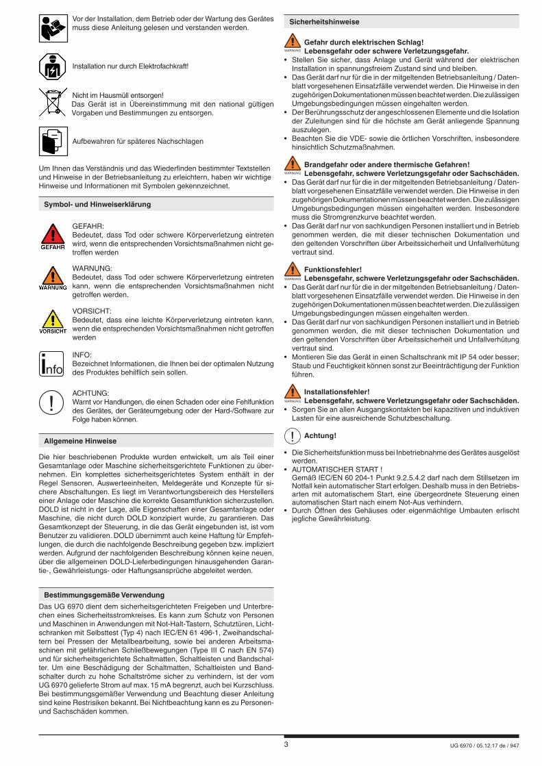
GEFAHR: Bedeutet, dass Tod oder schwere Körperverletzung eintreten
wird, wenn die entsprechenden Vorsichtsmaßnahmen nicht ge-troffen werden
WARNUNG: Bedeutet, dass Tod oder schwere Körperverletzung eintreten
kann, wenn die entsprechenden Vorsichtsmaßnahmen nicht getroffen werden.
VORSICHT: Bedeutet, dass eine leichte Körperverletzung eintreten kann,
wenn die entsprechenden Vorsichtsmaßnahmen nicht getroffen werden
! ACHTUNG:
Warnt vor Handlungen, die einen Schaden oder eine Fehlfunktion des Gerätes, der Geräteumgebung oder der Hard-/Software zur Folge haben können.
nfo INFO:
Bezeichnet Informationen, die Ihnen bei der optimalen Nutzung des Produktes behilflich sein sollen.
Die hier beschriebenen Produkte wurden entwickelt, um als Teil einer Gesamtanlage oder Maschine sicherheitsgerichtete Funktionen zu über-nehmen. Ein komplettes sicherheitsgerichtetes System enthält in der Regel Sensoren, Auswerteeinheiten, Meldegeräte und Konzepte für si-chere Abschaltungen. Es liegt im Verantwortungsbereich des Herstellers einer Anlage oder Maschine die korrekte Gesamtfunktion sicherzustellen. DOLD ist nicht in der Lage, alle Eigenschaften einer Gesamtanlage oder Maschine, die nicht durch DOLD konzipiert wurde, zu garantieren. Das Gesamtkonzept der Steuerung, in die das Gerät eingebunden ist, ist vom Benutzer zu validieren. DOLD übernimmt auch keine Haftung für Empfeh-lungen, die durch die nachfolgende Beschreibung gegeben bzw. impliziert werden. Aufgrund der nachfolgenden Beschreibung können keine neuen, über die allgemeinen DOLD-Lieferbedingungen hinausgehenden Garan-tie-, Gewährleistungs- oder Haftungsansprüche abgeleitet werden.
Allgemeine Hinweise
Symbol- und Hinweiserklärung
Bestimmungsgemäße Verwendung
Das UG 6970 dient dem sicherheitsgerichteten Freigeben und Unterbre-chen eines Sicherheitsstromkreises. Es kann zum Schutz von Personen und Maschinen in Anwendungen mit Not-Halt-Tastern, Schutztüren, Licht-schranken mit Selbsttest (Typ 4) nach IEC/EN 61 496-1, Zweihandschal-tern bei Pressen der Metallbearbeitung, sowie bei anderen Arbeitsma-schinen mit gefährlichen Schließbewegungen (Type III C nach EN 574) und für sicherheitsgerichtete Schaltmatten, Schaltleisten und Bandschal-ter. Um eine Beschädigung der Schaltmatten, Schaltleisten und Band-schalter durch zu hohe Schaltströme sicher zu verhindern, ist der vom UG 6970 gelieferte Strom auf max. 15 mA begrenzt, auch bei Kurzschluss. Bei bestimmungsgemäßer Verwendung und Beachtung dieser Anleitung sind keine Restrisiken bekannt. Bei Nichtbeachtung kann es zu Personen- und Sachschäden kommen.
Installation nur durch Elektrofachkraft!
Nicht im Hausmüll entsorgen! Das Gerät ist in Übereinstimmung mit den national gültigen Vorgaben und Bestimmungen zu entsorgen.
Aufbewahren für späteres Nachschlagen
Um Ihnen das Verständnis und das Wiederfinden bestimmter Textstellen und Hinweise in der Betriebsanleitung zu erleichtern, haben wir wichtige Hinweise und Informationen mit Symbolen gekennzeichnet.
Vor der Installation, dem Betrieb oder der Wartung des Gerätes muss diese Anleitung gelesen und verstanden werden.

4 UG 6970 / 05.12.17 de / 947
5 UG 6970 / 05.12.17 de / 947
0265
449
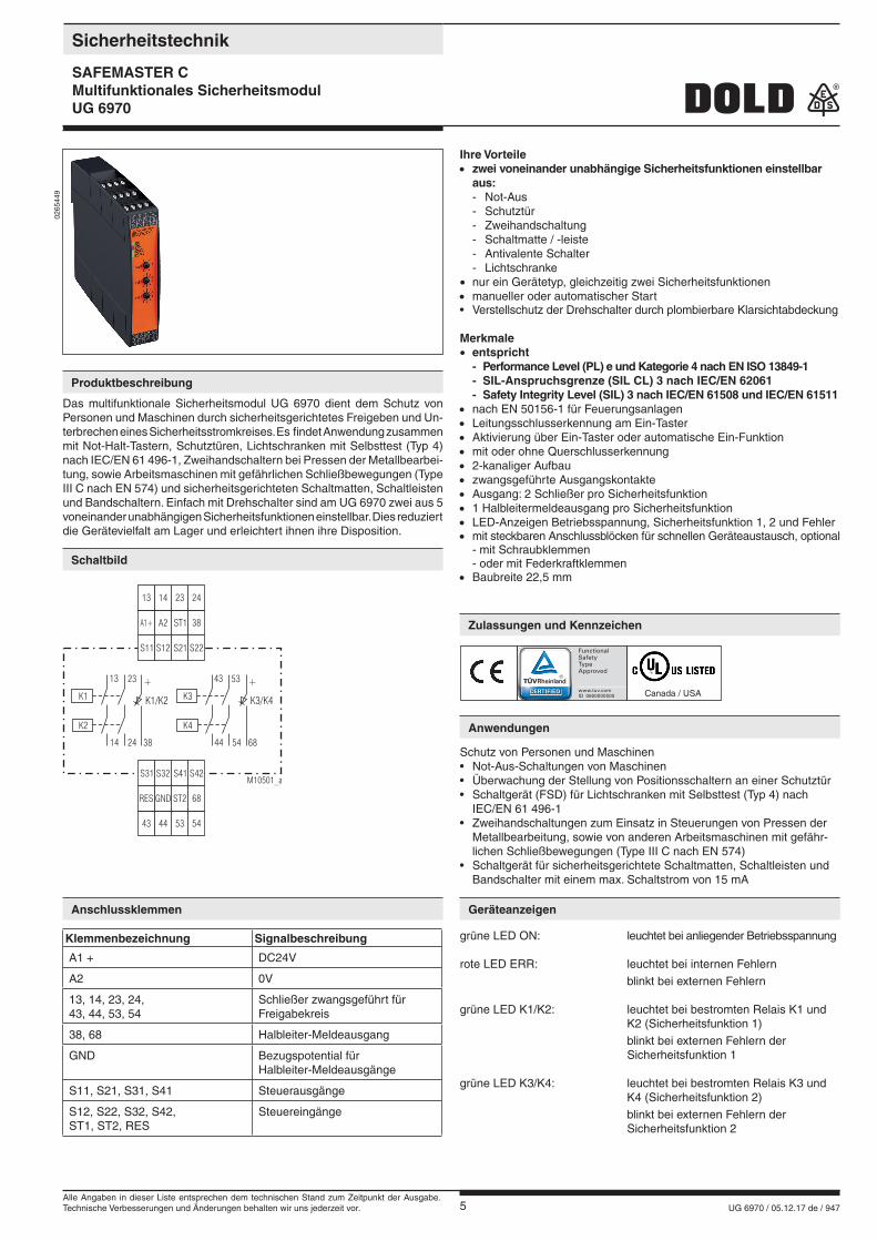
Das multifunktionale Sicherheitsmodul UG 6970 dient dem Schutz von Personen und Maschinen durch sicherheitsgerichtetes Freigeben und Un-terbrechen eines Sicherheitsstromkreises. Es findet Anwendung zusammen mit Not-Halt-Tastern, Schutztüren, Lichtschranken mit Selbsttest (Typ 4) nach IEC/EN 61 496-1, Zweihandschaltern bei Pressen der Metallbearbei-tung, sowie Arbeitsmaschinen mit gefährlichen Schließbewegungen (Type III C nach EN 574) und sicherheitsgerichteten Schaltmatten, Schaltleisten und Bandschaltern. Einfach mit Drehschalter sind am UG 6970 zwei aus 5 voneinander unabhängigen Sicherheitsfunktionen einstellbar. Dies reduziert die Gerätevielfalt am Lager und erleichtert ihnen ihre Disposition.
Canada / USA
Produktbeschreibung
Schaltbild
Anschlussklemmen Geräteanzeigen
Anwendungen
Zulassungen und Kennzeichen
Sicherheitstechnik
SAFEMASTER CMultifunktionales Sicherheitsmodul UG 6970
Ihre Vorteile• zwei voneinander unabhängige Sicherheitsfunktionen einstellbar aus: - Not-Aus - Schutztür - Zweihandschaltung - Schaltmatte / -leiste - Antivalente Schalter - Lichtschranke• nur ein Gerätetyp, gleichzeitig zwei Sicherheitsfunktionen• manueller oder automatischer Start • Verstellschutz der Drehschalter durch plombierbare Klarsichtabdeckung
Merkmale• entspricht - Performance Level (PL) e und Kategorie 4 nach EN ISO 13849-1 - SIL-Anspruchsgrenze (SIL CL) 3 nach IEC/EN 62061 - Safety Integrity Level (SIL) 3 nach IEC/EN 61508 und IEC/EN 61511• nach EN 50156-1 für Feuerungsanlagen• Leitungsschlusserkennung am Ein-Taster• Aktivierung über Ein-Taster oder automatische Ein-Funktion• mit oder ohne Querschlusserkennung• 2-kanaliger Aufbau• zwangsgeführte Ausgangskontakte• Ausgang: 2 Schließer pro Sicherheitsfunktion• 1 Halbleitermeldeausgang pro Sicherheitsfunktion• LED-Anzeigen Betriebsspannung, Sicherheitsfunktion 1, 2 und Fehler• mit steckbaren Anschlussblöcken für schnellen Geräteaustausch, optional - mit Schraubklemmen - oder mit Federkraftklemmen• Baubreite 22,5 mm
Klemmenbezeichnung Signalbeschreibung
A1 + DC24V
A2 0V
13, 14, 23, 24, 43, 44, 53, 54
Schließer zwangsgeführt für Freigabekreis
38, 68 Halbleiter-Meldeausgang
GND Bezugspotential für Halbleiter-Meldeausgänge
S11, S21, S31, S41 Steuerausgänge
S12, S22, S32, S42, ST1, ST2, RES
Steuereingänge
Schutz von Personen und Maschinen• Not-Aus-Schaltungen von Maschinen• Überwachung der Stellung von Positionsschaltern an einer Schutztür• Schaltgerät (FSD) für Lichtschranken mit Selbsttest (Typ 4) nach IEC/EN 61 496-1• Zweihandschaltungen zum Einsatz in Steuerungen von Pressen der Metallbearbeitung, sowie von anderen Arbeitsmaschinen mit gefähr- lichen Schließbewegungen (Type III C nach EN 574)• Schaltgerät für sicherheitsgerichtete Schaltmatten, Schaltleisten und Bandschalter mit einem max. Schaltstrom von 15 mA
grüne LED ON: leuchtet bei anliegender Betriebsspannung
rote LED ERR: leuchtet bei internen Fehlern blinkt bei externen Fehlern
grüne LED K1/K2: leuchtet bei bestromten Relais K1 und K2 (Sicherheitsfunktion 1) blinkt bei externen Fehlern der Sicherheitsfunktion 1
grüne LED K3/K4: leuchtet bei bestromten Relais K3 und K4 (Sicherheitsfunktion 2) blinkt bei externen Fehlern der Sicherheitsfunktion 2
S12
A2
14
44
GND
S32
S11
A1+
13
43
RES
S31
S21
ST1
23
53
ST2
S41
S22
38
24
54
68
S42M10501_a
13 43
K1 K3
K2 K4
23 53
14 4424 54
K3/K4K1/K2
++
6838
Alle Angaben in dieser Liste entsprechen dem technischen Stand zum Zeitpunkt der Ausgabe. Technische Verbesserungen und Änderungen behalten wir uns jederzeit vor.
6 UG 6970 / 05.12.17 de / 947
M10502_a
A1+ A2 S11RES S31S12 S32ST1 ST2S21 S41S22 S42 23 53
+ +
13 43
GND 24 38 685414 44
K1 K3K2 K4
K1/K2 K3/K4K2 K4
K1 K3
K3/K4K1/K2
ON
Überspannung- und
Kurzschlußschutz
Überwachungs-Logik
Funktion 1 Funktion 2
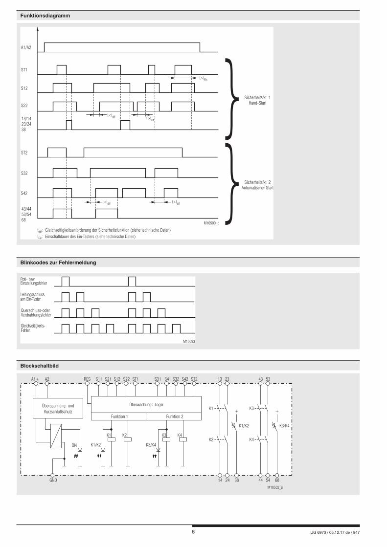
Blinkcodes zur Fehlermeldung
Funktionsdiagramm
Gleichzeitigkeits-Fehler
Querschluss-oderVerdrahtungsfehler
Leitungsschlussam Ein-Taster
Poti- bzw.Einstellungsfehler
M10693
Blockschaltbild
S22
S12
ST1
t>tEin
t>tdiff
t>tdifft<tdiff
t<tdiff
A1/A2
Sicherheitsfkt. 2Automatischer Start
Sicherheitsfkt. 1Hand-Start
13/1423/2438
ST2
S42
S32
43/4453/5468
M10500_c
t :
t : Einschaltdauer des Ein-Tasters (siehe technische Daten)diff
Ein
Gleichzeitigkeitsanforderung der Sicherheitsfunktion (siehe technische Daten)
7 UG 6970 / 05.12.17 de / 947
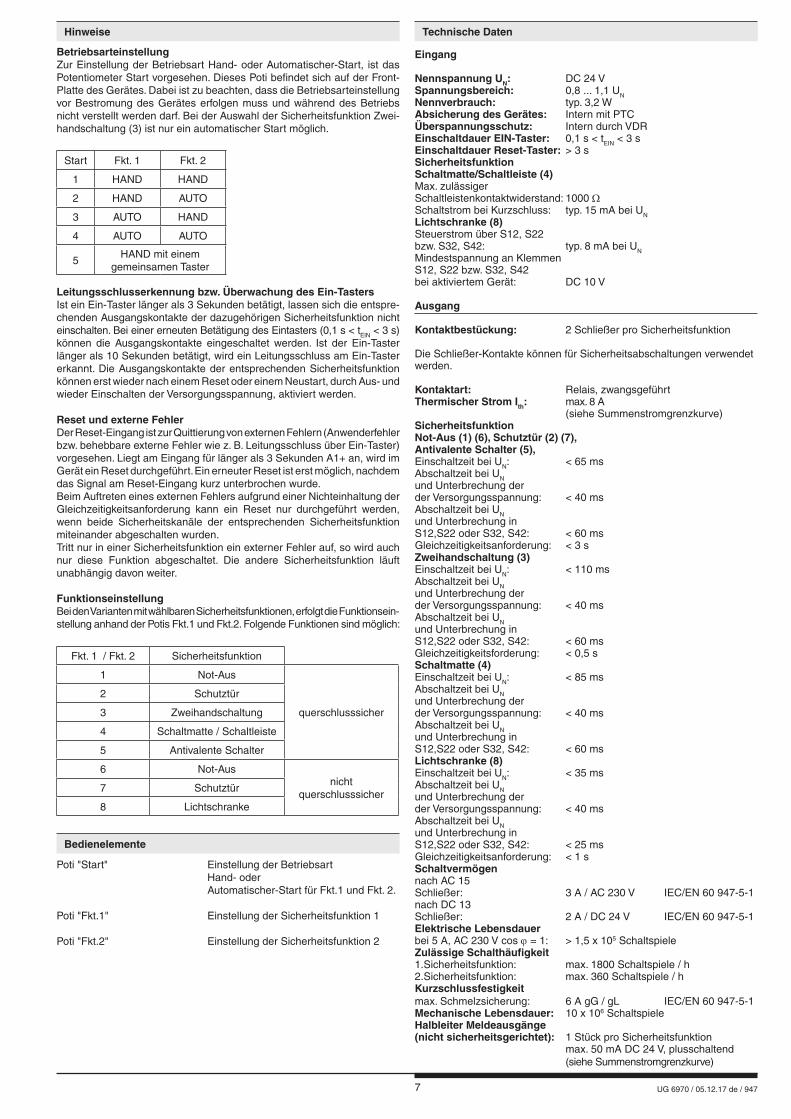
Eingang
Nennspannung UN: DC 24 VSpannungsbereich: 0,8 ... 1,1 UNNennverbrauch: typ. 3,2 WAbsicherung des Gerätes: Intern mit PTCÜberspannungsschutz: Intern durch VDREinschaltdauer EIN-Taster: 0,1 s < tEIN < 3 sEinschaltdauer Reset-Taster: > 3 sSicherheitsfunktion Schaltmatte/Schaltleiste (4)Max. zulässiger Schaltleistenkontaktwiderstand: 1000 ΩSchaltstrom bei Kurzschluss: typ. 15 mA bei UNLichtschranke (8)Steuerstrom über S12, S22bzw. S32, S42: typ. 8 mA bei UNMindestspannung an Klemmen S12, S22 bzw. S32, S42bei aktiviertem Gerät: DC 10 V
Ausgang
Kontaktbestückung: 2 Schließer pro Sicherheitsfunktion
Die Schließer-Kontakte können für Sicherheitsabschaltungen verwendet werden.
Kontaktart: Relais, zwangsgeführtThermischer Strom Ith: max. 8 A (siehe Summenstromgrenzkurve)SicherheitsfunktionNot-Aus (1) (6), Schutztür (2) (7),Antivalente Schalter (5),Einschaltzeit bei UN: < 65 msAbschaltzeit bei UNund Unterbrechung der der Versorgungsspannung: < 40 msAbschaltzeit bei UNund Unterbrechung inS12,S22 oder S32, S42: < 60 msGleichzeitigkeitsanforderung: < 3 sZweihandschaltung (3)Einschaltzeit bei UN: < 110 msAbschaltzeit bei UNund Unterbrechung der der Versorgungsspannung: < 40 msAbschaltzeit bei UNund Unterbrechung inS12,S22 oder S32, S42: < 60 msGleichzeitigkeitsforderung: < 0,5 sSchaltmatte (4)Einschaltzeit bei UN: < 85 msAbschaltzeit bei UNund Unterbrechung der der Versorgungsspannung: < 40 msAbschaltzeit bei UNund Unterbrechung inS12,S22 oder S32, S42: < 60 msLichtschranke (8)Einschaltzeit bei UN: < 35 msAbschaltzeit bei UNund Unterbrechung der der Versorgungsspannung: < 40 msAbschaltzeit bei UNund Unterbrechung inS12,S22 oder S32, S42: < 25 msGleichzeitigkeitsanforderung: < 1 sSchaltvermögennach AC 15Schließer: 3 A / AC 230 V IEC/EN 60 947-5-1nach DC 13Schließer: 2 A / DC 24 V IEC/EN 60 947-5-1Elektrische Lebensdauerbei 5 A, AC 230 V cos j = 1: > 1,5 x 10⁵ SchaltspieleZulässige Schalthäufigkeit 1.Sicherheitsfunktion: max. 1800 Schaltspiele / h2.Sicherheitsfunktion: max. 360 Schaltspiele / hKurzschlussfestigkeitmax. Schmelzsicherung: 6 A gG / gL IEC/EN 60 947-5-1Mechanische Lebensdauer: 10 x 106 SchaltspieleHalbleiter Meldeausgänge(nicht sicherheitsgerichtet): 1 Stück pro Sicherheitsfunktion max. 50 mA DC 24 V, plusschaltend (siehe Summenstromgrenzkurve)
Hinweise Technische Daten
BetriebsarteinstellungZur Einstellung der Betriebsart Hand- oder Automatischer-Start, ist das Potentiometer Start vorgesehen. Dieses Poti befindet sich auf der Front-Platte des Gerätes. Dabei ist zu beachten, dass die Betriebsarteinstellung vor Bestromung des Gerätes erfolgen muss und während des Betriebs nicht verstellt werden darf. Bei der Auswahl der Sicherheitsfunktion Zwei-handschaltung (3) ist nur ein automatischer Start möglich.
Start Fkt. 1 Fkt. 2
1 HAND HAND
2 HAND AUTO
3 AUTO HAND
4 AUTO AUTO
5HAND mit einem
gemeinsamen Taster
Leitungsschlusserkennung bzw. Überwachung des Ein-TastersIst ein Ein-Taster länger als 3 Sekunden betätigt, lassen sich die entspre-chenden Ausgangskontakte der dazugehörigen Sicherheitsfunktion nicht einschalten. Bei einer erneuten Betätigung des Eintasters (0,1 s < tEIN < 3 s) können die Ausgangskontakte eingeschaltet werden. Ist der Ein-Taster länger als 10 Sekunden betätigt, wird ein Leitungsschluss am Ein-Taster erkannt. Die Ausgangskontakte der entsprechenden Sicherheitsfunktion können erst wieder nach einem Reset oder einem Neustart, durch Aus- und wieder Einschalten der Versorgungsspannung, aktiviert werden.
Reset und externe FehlerDer Reset-Eingang ist zur Quittierung von externen Fehlern (Anwenderfehler bzw. behebbare externe Fehler wie z. B. Leitungsschluss über Ein-Taster) vorgesehen. Liegt am Eingang für länger als 3 Sekunden A1+ an, wird im Gerät ein Reset durchgeführt. Ein erneuter Reset ist erst möglich, nachdem das Signal am Reset-Eingang kurz unterbrochen wurde.Beim Auftreten eines externen Fehlers aufgrund einer Nichteinhaltung der Gleichzeitigkeitsanforderung kann ein Reset nur durchgeführt werden, wenn beide Sicherheitskanäle der entsprechenden Sicherheitsfunktion miteinander abgeschalten wurden.Tritt nur in einer Sicherheitsfunktion ein externer Fehler auf, so wird auch nur diese Funktion abgeschaltet. Die andere Sicherheitsfunktion läuft unabhängig davon weiter. FunktionseinstellungBei den Varianten mit wählbaren Sicherheitsfunktionen, erfolgt die Funktionsein-stellung anhand der Potis Fkt.1 und Fkt.2. Folgende Funktionen sind möglich:
Fkt. 1 / Fkt. 2 Sicherheitsfunktion
1 Not-Aus
querschlusssicher
2 Schutztür
3 Zweihandschaltung
4 Schaltmatte / Schaltleiste
5 Antivalente Schalter
6 Not-Ausnicht
querschlusssicher7 Schutztür
8 Lichtschranke
Poti "Start" Einstellung der Betriebsart Hand- oder Automatischer-Start für Fkt.1 und Fkt. 2.
Poti "Fkt.1" Einstellung der Sicherheitsfunktion 1
Poti "Fkt.2" Einstellung der Sicherheitsfunktion 2
Bedienelemente
8 UG 6970 / 05.12.17 de / 947
UG 6970.04PS/61 DC24VArtikelnummer: 0065426• 1. Sicherheitsfunktion: einstellbar• 2. Sicherheitsfunktion: einstellbar• Ausgang: 2 Schließer pro Sicherheitsfunktion• Nennspannung: DC 24 V• Baubreite: 22,5 mm
Allgemeine Daten
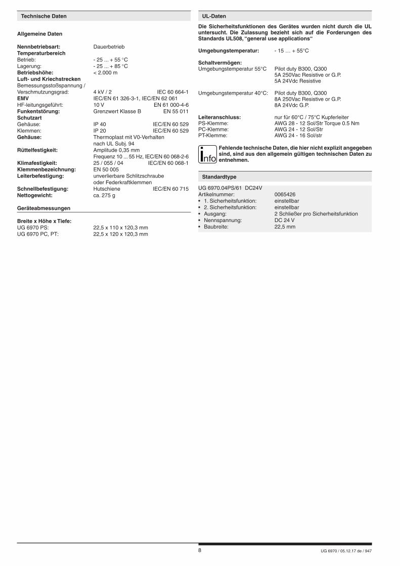
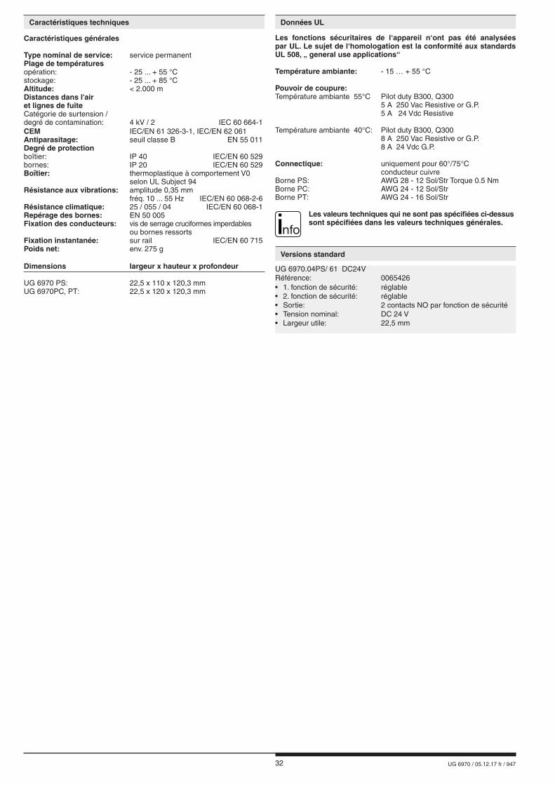
Nennbetriebsart: DauerbetriebTemperaturbereichBetrieb: - 25 ... + 55 °CLagerung: - 25 ... + 85 °CBetriebshöhe: < 2.000 mLuft- und KriechstreckenBemessungsstoßspannung /Verschmutzungsgrad: 4 kV / 2 IEC 60 664-1EMV IEC/EN 61 326-3-1, IEC/EN 62 061HF-leitungsgeführt: 10 V EN 61 000-4-6Funkentstörung: Grenzwert Klasse B EN 55 011SchutzartGehäuse: IP 40 IEC/EN 60 529Klemmen: IP 20 IEC/EN 60 529Gehäuse: Thermoplast mit V0-Verhalten nach UL Subj. 94Rüttelfestigkeit: Amplitude 0,35 mm Frequenz 10 ... 55 Hz, IEC/EN 60 068-2-6Klimafestigkeit: 25 / 055 / 04 IEC/EN 60 068-1Klemmenbezeichnung: EN 50 005Leiterbefestigung: unverlierbare Schlitzschraube oder FederkraftklemmenSchnellbefestigung: Hutschiene IEC/EN 60 715Nettogewicht: ca. 275 g
Geräteabmessungen
Breite x Höhe x Tiefe: UG 6970 PS: 22,5 x 110 x 120,3 mmUG 6970 PC, PT: 22,5 x 120 x 120,3 mm
Die Sicherheitsfunktionen des Gerätes wurden nicht durch die UL untersucht. Die Zulassung bezieht sich auf die Forderungen des Standards UL508, “general use applications“
Umgebungstemperatur: - 15 … + 55°C
Schaltvermögen:Umgebungstemperatur 55°C Pilot duty B300, Q300 5A 250Vac Resistive or G.P. 5A 24Vdc Resistive
Umgebungstemperatur 40°C: Pilot duty B300, Q300 8A 250Vac Resistive or G.P. 8A 24Vdc G.P. Leiteranschluss: nur für 60°C / 75°C KupferleiterPS-Klemme: AWG 28 - 12 Sol/Str Torque 0.5 NmPC-Klemme: AWG 24 - 12 Sol/StrPT-Klemme: AWG 24 - 16 Sol/str
nfoFehlende technische Daten, die hier nicht explizit angegeben sind, sind aus den allgemein gültigen technischen Daten zu entnehmen.
Technische Daten UL-Daten
Standardtype
9 UG 6970 / 05.12.17 de / 947
Fehler mögliche Ursache
LED "ON" leuchtet nicht - Versorgungsspannung A1+/A2 nicht angeschlossen
LED "ERR" blinkt im Verhältnis 1:1
- Unter- oder Überspannungsfehler (Versorgungsspannung A1+/A2 prüfen)
LED "ERR" blinkt im Verhältnis 4:1
- externer Fehler (genaue Fehler- beschreibung siehe Blinkcodes)
LED "ERR" leuchtet dauerhaft - Gerätefehler (wenn nach Neustart immer noch anliegt, Gerät austauschen)
- Das Gerät enthält keine Teile, die einer Wartung bedürfen.- Bei vorliegenden Fehlern das Gerät nicht öffnen, sondern an den Hersteller zur Reparatur schicken.
Wartung und Instandsetzung
Vorgehen bei Störungen
Bestellbeispiel Kennlinien
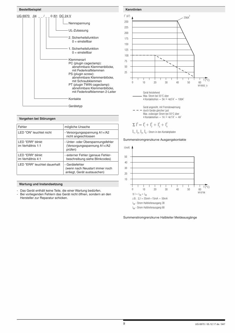
UG 6970 .04 _ _ / _ _ 0 /61 DC 24 V
Nennspannung
UL-Zulassung 2. Sicherheitsfunktion 0 = einstellbar 1. Sicherheitsfunktion 0 = einstellbar Klemmenart PC (plugin cageclamp): abnehmbare Klemmenblöcke, mit Feder kraft klemmen PS (plugin screw): abnehmbare Klemmenblöcke, mit Schraubklemmen PT (plugin TWIN cageclamp): abnehmbare Klemmenblöcke, mit Federkraftklemmen 2-Leiter Kontakte Gerätetyp
Summenstromgrenzkurve Ausgangskontakte
Summenstromgrenzkurve Halbleiter Meldeausgänge
M10796
10
I(mA)
30
40
50
20
0 10 20 30 40 6050T ( C)°
� I = I + I38 68
z.B. : � �I 35mA+15mA = 50mA
I - Strom Halbleiterausgang 3838
I - Strom Halbleiterausgang 6868
M10692_b
25
I2
(A )2
75
100
125
50
0 10 20 30 40 6050T ( C)°
- Strom in den KontaktpfadenI , I , I , I1 2 3 4
� I = I + I + I + I2 2 2 2 2
1 2 3 4
Gerät angereiht, mit Fremderwärmungdurch Geräte gleicher LastMax. zulässiger Strom bei 55°C über4 Kontaktreihen = 1A = 4x1 A = 4A
2 2 2^
Gerät freistehendMax. Strom bei 55°C über4 Kontaktreihen = 5A = 4x5 A = 100A
2 2 2^
150
175
200
225
250
256A2
10 UG 6970 / 05.12.17 de / 947
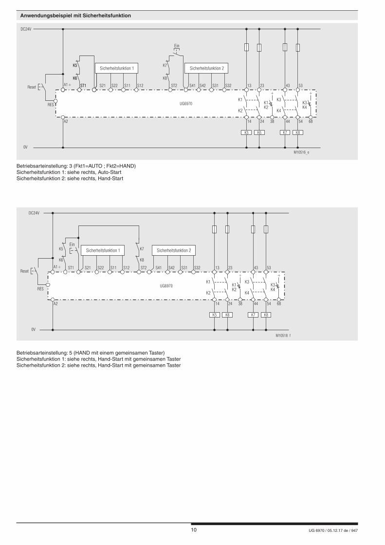
Anwendungsbeispiel mit Sicherheitsfunktion
Betriebsarteinstellung: 3 (Fkt1=AUTO ; Fkt2=HAND)Sicherheitsfunktion 1: siehe rechts, Auto-Start Sicherheitsfunktion 2: siehe rechts, Hand-Start
Betriebsarteinstellung: 5 (HAND mit einem gemeinsamen Taster)Sicherheitsfunktion 1: siehe rechts, Hand-Start mit gemeinsamen TasterSicherheitsfunktion 2: siehe rechts, Hand-Start mit gemeinsamen Taster
DC24V
0V
A1+
A2
ST1
K6 K8
K5 K7
ST2 S42S41 S31 S32 13 4323 53
24 5438 6814 44
M10516_e
K1 K3K1 K3K2 K4
K2 K4
Ein
K5 K6 K7 K8
+ +
UG6970
S22S21 S11 S12
Sicherheitsfunktion 1 Sicherheitsfunktion 2
Reset ST1
K6
K5
RES
DC24V
0V
A1+
A2
K6 K8
K5 K7
S41ST2ST1 13 4323 53
24 5438 6814 44
M10518_f
K1 K3K1 K3K2 K4
K2 K4
UG6970
K5 K6 K7 K8
+ +
Ein
S22 S31S21 S42S11 S32S12
Sicherheitsfunktion 1 Sicherheitsfunktion 2
Reset
RES
11 UG 6970 / 05.12.17 de / 947
Anwendungsbeispiel mit Sicherheitsfunktion 1
Anwendungsbeispiel mit Sicherheitsfunktion 2
S22 S11 S12
M10757
Not-Aus
S21 S21 S22 S11 S12
Schiebeschutztürgeschlossen
M10756
S1 S2
S22S21 S11 S12
M10750
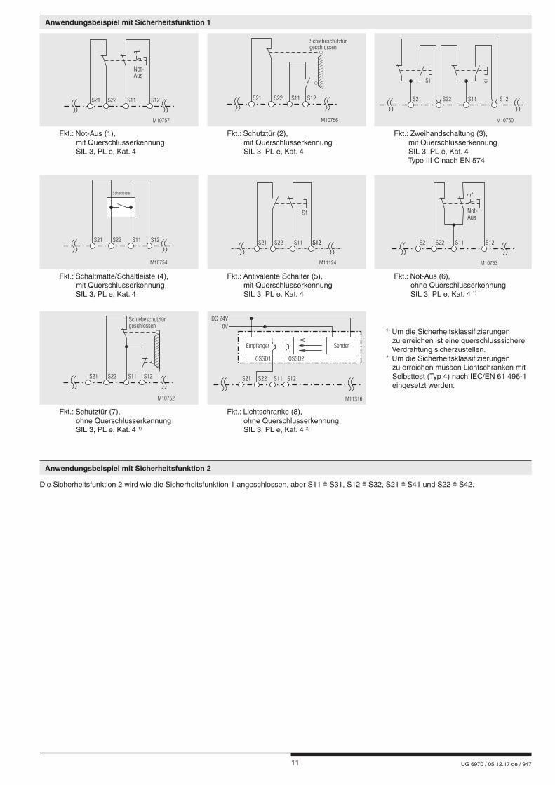
Fkt.: Not-Aus (1), mit Querschlusserkennung SIL 3, PL e, Kat. 4
Fkt.: Schutztür (2), mit Querschlusserkennung SIL 3, PL e, Kat. 4
Fkt.: Zweihandschaltung (3), mit Querschlusserkennung SIL 3, PL e, Kat. 4 Type III C nach EN 574
S21 S22 S11 S12
Schaltleiste
M10754
S22 S11 S12S12
S1
M11124
S21 S22 S11 S12
M10753
Not-Aus
S21
Fkt.: Schaltmatte/Schaltleiste (4), mit Querschlusserkennung SIL 3, PL e, Kat. 4
Fkt.: Antivalente Schalter (5), mit Querschlusserkennung SIL 3, PL e, Kat. 4
Fkt.: Not-Aus (6), ohne Querschlusserkennung SIL 3, PL e, Kat. 4 1)
S21 S22 S11 S12
Schiebeschutztürgeschlossen
M10752
OSSD1 OSSD2
S22S21 S11 S12
SenderEmpfänger
DC 24V
0V
M11316
++
1) Um die Sicherheitsklassifizierungen zu erreichen ist eine querschlusssichere Verdrahtung sicherzustellen.2) Um die Sicherheitsklassifizierungen zu erreichen müssen Lichtschranken mit Selbsttest (Typ 4) nach IEC/EN 61 496-1 eingesetzt werden.
Fkt.: Schutztür (7), ohne Querschlusserkennung SIL 3, PL e, Kat. 4 1)
Fkt.: Lichtschranke (8), ohne Querschlusserkennung SIL 3, PL e, Kat. 4 2)
Die Sicherheitsfunktion 2 wird wie die Sicherheitsfunktion 1 angeschlossen, aber S11 S31, S12 S32, S21 S41 und S22 S42.

12 UG 6970 / 05.12.17 de / 947
E. DOLD & SÖHNE KG • D-78114 Furtwangene-mail: [email protected] • internet: http://www.dold.com
• Postfach 1251 • Telefon 0 77 23 / 654-0 • Telefax 0 77 23 / 654-356
13 UG 6970 / 05.12.17 en / 947
Datasheet / Operating Instructions ENGLISH
E. DOLD & SÖHNE KGP.O. Box 1251 • D-78114 Furtwangen • GermanyTel: +49 7723 6540 • Fax +49 7723 [email protected] • www.dold.com
Translation of the original instructions
SAFEMASTER C Multifunctional Safety Module UG 6970
0266691
14 UG 6970 / 05.12.17 en / 947
Contents
Symbol and Notes Statement ..........................................................................................................................................15
General Notes .................................................................................................................................................................15
Designated Use ...............................................................................................................................................................15
Safety Notes ....................................................................................................................................................................15
Product Description .........................................................................................................................................................17
Circuit Diagram ................................................................................................................................................................17
Connection Terminals ......................................................................................................................................................17
Approvals and Markings ..................................................................................................................................................17
Application .......................................................................................................................................................................17
Indicators .........................................................................................................................................................................17
Function Diagram ............................................................................................................................................................18
Fault Indication by Flashing Code ...................................................................................................................................18
Block Diagram .................................................................................................................................................................18
Practical Notes ................................................................................................................................................................19
Operating Potentiometer ..................................................................................................................................................19
Technical Data .................................................................................................................................................................19
Technical Data .................................................................................................................................................................20
UL-Data ...........................................................................................................................................................................20
Standard Type ..................................................................................................................................................................20
Variants ............................................................................................................................................................................21
Troubleshooting ...............................................................................................................................................................21
Maintenance and Repairs ................................................................................................................................................21
Characteristics .................................................................................................................................................................21
Application Examples with safety function .......................................................................................................................22
Application Examples with safety function 1 ....................................................................................................................23
Application Examples with safety function 2 ....................................................................................................................23
Labeling and connections ................................................................................................................................................37
Dimensions (dimensions in mm) .....................................................................................................................................38
Mounting / disassembly of the PS / PC / PT-terminal blocks ...........................................................................................38
Safety related data ..........................................................................................................................................................39
CE-Declaration of Conformity ..........................................................................................................................................40
15 UG 6970 / 05.12.17 en / 947
Safety Notes
WARNING
Risk of electrocution! Danger to life or risk of serious injuries. • Disconnect the system and device from the power supply and ensure they remain disconnected during electrical installation.• The device may only be used for the applications described in the mu-
tually applicable operating instructions / data sheet. The notes in the respective documentation must be heeded. The permissible ambient conditions must be observed.
• The contact protection of the elements connected and the insulation of the supply cables must be designed in accordance with the requirements in the operating instructions / data sheet.
• Note the VDE and local regulations, particularly those related to protec-tive measures.
WARNING
Risk of fire or other thermal hazards! Danger to life, risk of serious injuries or property damage. • The device may only be used for the applications described in the mutually
applicable operating instructions / data sheet. The notes in the respective documentation must be heeded. The permissible ambient conditions must be observed. In particular, the current limit curve must be heeded.
• The device may only be installed and put into operation by experts who are familiar with this technical documentation and the applicable health and safety and accident prevention regulations.
WARNING
Functional error! Danger to life, risk of serious injuries or property damage. • The device may only be used for the applications described in the mu-
tually applicable operating instructions / data sheet. The notes in the respective documentation must be heeded. The permissible ambient conditions must be observed.
• The device may only be installed and put into operation by experts who are familiar with this technical documentation and the applicable health and safety and accident prevention regulations.
• The unit should be panel mounted in an enclosure rated at IP 54 or superior. Dust and dampness may lead to malfunction.
WARNING
Installation fault! Danger to life, risk of serious injuries or property damage. • Make sure of sufficient protection circuitry at all output contacts for
capacitive and inductive loads.
! Attention! • The safety function must be triggered during commissioning.• AUTOMATIC START ! According to IEC/EN 60 204-1 part 9.2.5.4.2 and 10.8.3 it is not allowed to restart automatically after emergency stop. Therefore the machine control has to disable the automatic start after emergency stop.• Opening the device or implementing unauthorized changes voids any warranty
DANGER
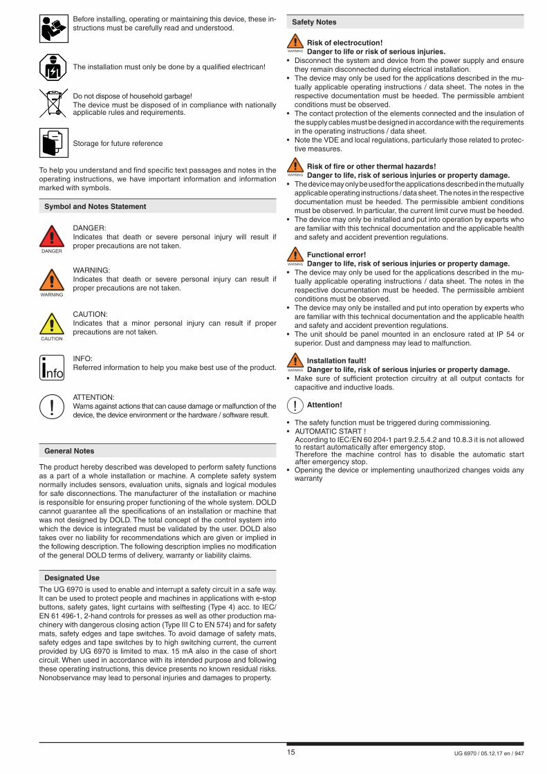
DANGER: Indicates that death or severe personal injury will result if
proper precautions are not taken.
WARNING
WARNING: Indicates that death or severe personal injury can result if
proper precautions are not taken.
CAUTION
CAUTION: Indicates that a minor personal injury can result if proper
precautions are not taken.
! ATTENTION:
Warns against actions that can cause damage or malfunction of the device, the device environment or the hardware / software result.
nfo INFO:
Referred information to help you make best use of the product.
Symbol and Notes Statement
The installation must only be done by a qualified electrican!
Do not dispose of household garbage! The device must be disposed of in compliance with nationally
applicable rules and requirements.
To help you understand and find specific text passages and notes in the operating instructions, we have important information and information marked with symbols.
Before installing, operating or maintaining this device, these in-structions must be carefully read and understood.
The product hereby described was developed to perform safety functions as a part of a whole installation or machine. A complete safety system normally includes sensors, evaluation units, signals and logical modules for safe disconnections. The manufacturer of the installation or machine is responsible for ensuring proper functioning of the whole system. DOLD cannot guarantee all the specifications of an installation or machine that was not designed by DOLD. The total concept of the control system into which the device is integrated must be validated by the user. DOLD also takes over no liability for recommendations which are given or implied in the following description. The following description implies no modification of the general DOLD terms of delivery, warranty or liability claims.
General Notes
Designated Use
The UG 6970 is used to enable and interrupt a safety circuit in a safe way. It can be used to protect people and machines in applications with e-stop buttons, safety gates, light curtains with selftesting (Type 4) acc. to IEC/EN 61 496-1, 2-hand controls for presses as well as other production ma-chinery with dangerous closing action (Type III C to EN 574) and for safety mats, safety edges and tape switches. To avoid damage of safety mats, safety edges and tape switches by to high switching current, the current provided by UG 6970 is limited to max. 15 mA also in the case of short circuit. When used in accordance with its intended purpose and following these operating instructions, this device presents no known residual risks. Nonobservance may lead to personal injuries and damages to property.
Storage for future reference

16 UG 6970 / 05.12.17 en / 947
17 UG 6970 / 05.12.17 en / 947
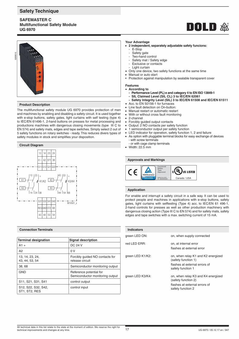
Your Advantage• 2 independent, separately adjustable safety funcions: - E-Stop - Safety gate - Two-hand control - Safety mat / Safety edge - Exclusive or contacts - Light curtain• Only one device, two safety functions at the same time• Manual or auto start • Protection against manipulation by sealable transparent cover
Features• According to - Performance Level (PL) e and category 4 to EN ISO 13849-1 - SIL Claimed Level (SIL CL) 3 to IEC/EN 62061 - Safety Integrity Level (SIL) 3 to IEC/EN 61508 and IEC/EN 61511• Acc. to EN 50156-1 for furnaces• Line fault detection on On-button:• Manual restart or automatic restart• With or without cross fault monitoring• 2-channel• Forcibly guided output contacts• Output: 2 NO contacts per safety function• 1 semiconductor output per safety function• LED indicator for operation, safety function 1, 2 and failure• As option with pluggable terminal blocks for easy exchange of devices - with screw terminals - or with cage clamp terminals• Width: 22.5 mm
0269
010
For enable and interrupt a safety circuit in a safe way. It can be used to protect people and machines in applications with e-stop buttons, safety gates, light curtains with selftesting (Type 4) acc. to IEC/EN 61 496-1, 2-hand controls for presses as well as other production machinery with dangerous closing action (Type III C to EN 574) and for safety mats, safety edges and tape switches with a max. switching current of 15 mA.
S12
A2
14
44
GND
S32
S11
A1+
13
43
RES
S31
S21
ST1
23
53
ST2
S41
S22
38
24
54
68
S42M10501_a
13 43
K1 K3
K2 K4
23 53
14 4424 54
K3/K4K1/K2
++
6838
green LED ON: on, when supply connected
red LED ERR: on, at internal error flashes at external error
green LED K1/K2: on, when relay K1 and K2 energized (safety function 1) flashes at external errors of safety function 1
green LED K3/K4: on, when relay K3 and K4 energized (safety function 2) flashes at external errors of safety function 2
Terminal designation Signal description
A1 + DC 24 V
A2 0 V
13, 14, 23, 24, 43, 44, 53, 54
Forcibly guided NO contacts for release circuit
38, 68 Semiconductor monitoring output
GND Reference potential for Semiconductor monitoring output
S11, S21, S31, S41 control output
S12, S22, S32, S42, ST1, ST2, RES
control input
Canada / USA
The multifunctional safety module UG 6970 provides protection of men and machines by enabling and disabling a safety circuit. It is used together with e-stop buttons, safety gates, light curtains with self testing (type 4) to IEC/EN 61496-1, 2-hand buttons on presses for metal processing and productions machines with dangerous closing movements (type III C to EN 574) and safety mats, edges and tape switches. Simply select 2 out of 5 safety functions on rotary switches - ready. This reduces divers types of safety modules in stock and simplifies your disposition.
Safety Technique
SAFEMASTER CMultifunctional Safety Module UG 6970
Product Description
Circuit Diagram
Connection Terminals
Approvals and Markings
Application
Indicators
All technical data in this list relate to the state at the moment of edition. We reserve the right for technical improvements and changes at any time.
18 UG 6970 / 05.12.17 en / 947
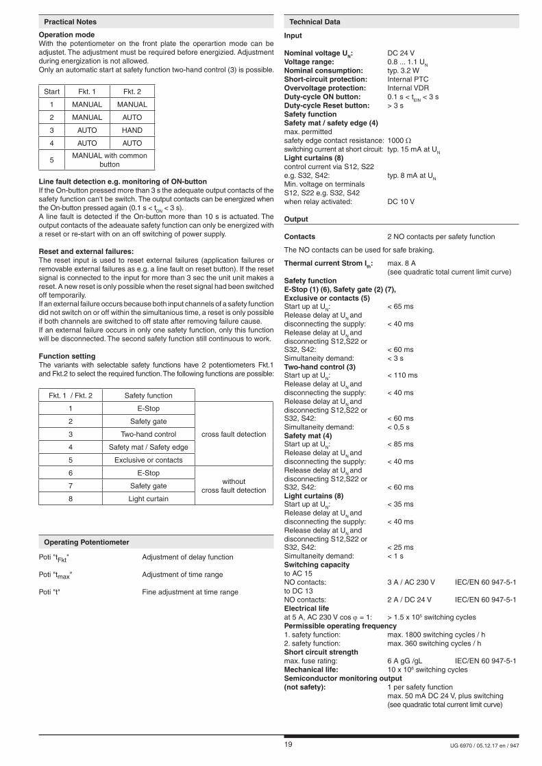
Fault Indication by Flashing Code
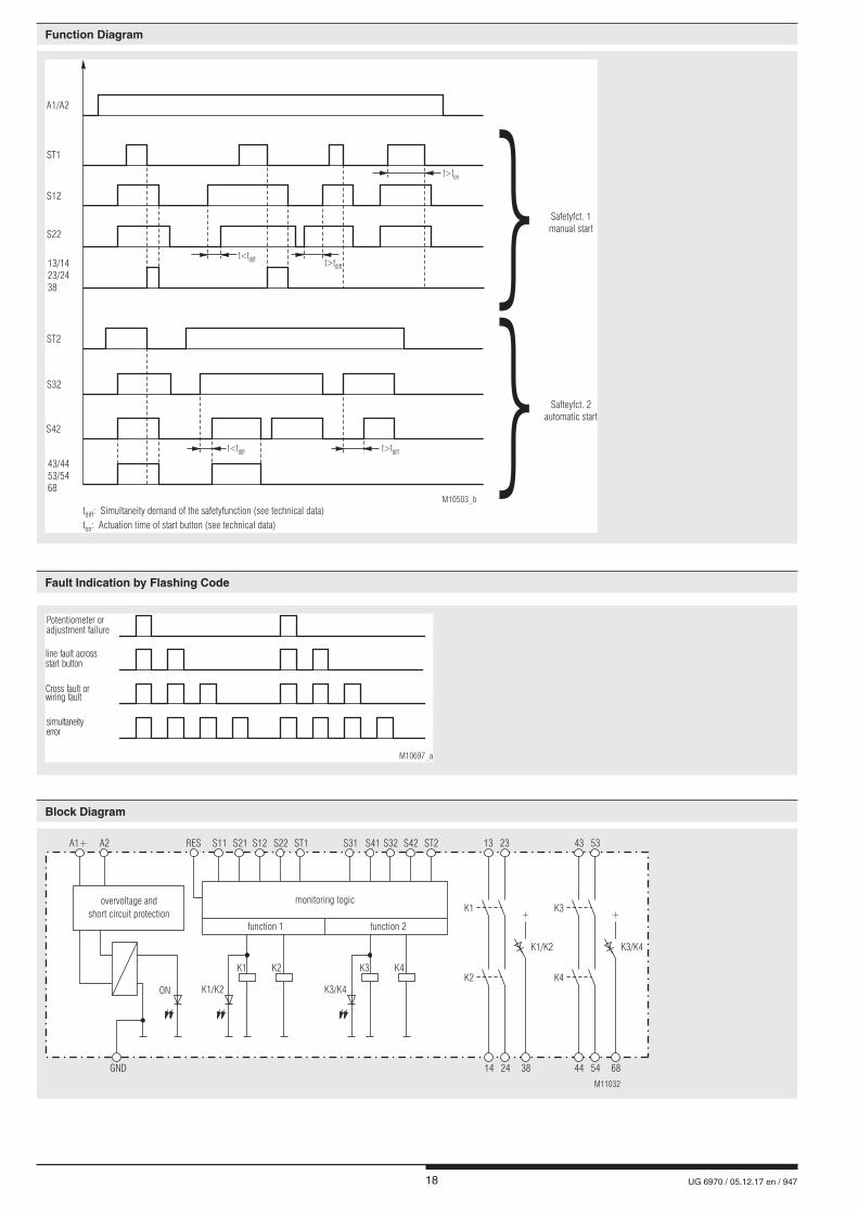
Function Diagram
simultaneityerror
Potentiometer oradjustment failure
line fault acrossstart button
Cross fault orwiring fault
M10697_a
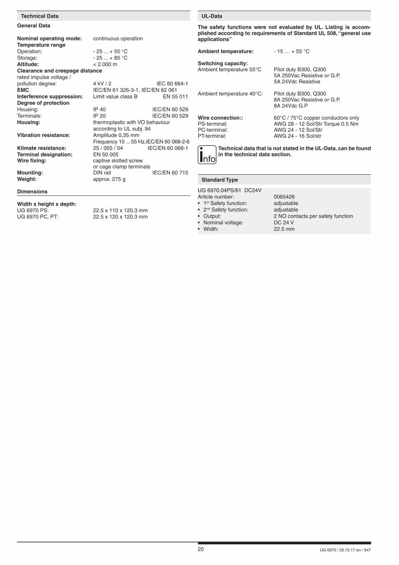
Block Diagram
M11032
A1+ A2 S11RES S31S12 S32ST1 ST2S21 S41S22 S42 23 53
+ +
13 43
GND 24 38 685414 44
K1 K3K2 K4
K1/K2 K3/K4K2 K4
K1 K3
K3/K4K1/K2
ON
monitoring logic
function 1 function 2
overvoltage and
short circuit protection
Safteyfct. 2automatic start
Safetyfct. 1manual start
M10503_b
S22
S12
ST1
t>ton
t>tdiff
t>tdifft<tdiff
t<tdiff
A1/A2
13/1423/2438
ST2
S42
S32
43/4453/5468
t : Simultaneity demand of the safetyfunction (see technical data)
t : Actuation time of start button (see technical data)diff
on
19 UG 6970 / 05.12.17 en / 947
Input
Nominal voltage UN: DC 24 VVoltage range: 0.8 ... 1.1 UN
Nominal consumption: typ. 3.2 WShort-circuit protection: Internal PTCOvervoltage protection: Internal VDRDuty-cycle ON button: 0.1 s < tEIN < 3 sDuty-cycle Reset button: > 3 sSafety function Safety mat / safety edge (4)max. permitted safety edge contact resistance: 1000 Ωswitching current at short circuit: typ. 15 mA at UN
Light curtains (8)control current via S12, S22e.g. S32, S42: typ. 8 mA at UN
Min. voltage on terminals S12, S22 e.g. S32, S42when relay activated: DC 10 V
Output
Contacts 2 NO contacts per safety function
The NO contacts can be used for safe braking.
Thermal current Strom Ith: max. 8 A (see quadratic total current limit curve)Safety functionE-Stop (1) (6), Safety gate (2) (7),Exclusive or contacts (5)Start up at UN: < 65 msRelease delay at UN and disconnecting the supply: < 40 msRelease delay at UN and disconnecting S12,S22 or S32, S42: < 60 msSimultaneity demand: < 3 sTwo-hand control (3)Start up at UN: < 110 msRelease delay at UN and disconnecting the supply: < 40 msRelease delay at UN and disconnecting S12,S22 orS32, S42: < 60 msSimultaneity demand: < 0,5 sSafety mat (4)Start up at UN: < 85 msRelease delay at UN and disconnecting the supply: < 40 msRelease delay at UN and disconnecting S12,S22 orS32, S42: < 60 msLight curtains (8)Start up at UN: < 35 msRelease delay at UN and disconnecting the supply: < 40 msRelease delay at UN and disconnecting S12,S22 or S32, S42: < 25 msSimultaneity demand: < 1 sSwitching capacityto AC 15NO contacts: 3 A / AC 230 V IEC/EN 60 947-5-1to DC 13NO contacts: 2 A / DC 24 V IEC/EN 60 947-5-1Electrical lifeat 5 A, AC 230 V cos j = 1: > 1.5 x 10⁵ switching cyclesPermissible operating frequency 1. safety function: max. 1800 switching cycles / h2. safety function: max. 360 switching cycles / hShort circuit strengthmax. fuse rating: 6 A gG /gL IEC/EN 60 947-5-1Mechanical life: 10 x 106 switching cyclesSemiconductor monitoring output(not safety): 1 per safety function max. 50 mA DC 24 V, plus switching (see quadratic total current limit curve)
Technical Data
Operation modeWith the potentiometer on the front plate the operartion mode can be adjustet. The adjustment must be required before energizied. Adjustment during energization is not allowed.Only an automatic start at safety function two-hand control (3) is possible.
Start Fkt. 1 Fkt. 2
1 MANUAL MANUAL
2 MANUAL AUTO
3 AUTO HAND
4 AUTO AUTO
5MANUAL with common
button
Line fault detection e.g. monitoring of ON-buttonIf the On-button pressed more than 3 s the adequate output contacts of the safety function can't be switch. The output contacts can be energized when the On-button pressed again (0.1 s < tON < 3 s).A line fault is detected if the On-button more than 10 s is actuated. The output contacts of the adeauate safety function can only be energized with a reset or re-start with on an off switching of power supply.
Reset and external failures:The reset input is used to reset external failures (application failures or removable external failures as e.g. a line fault on reset button). If the reset signal is connected to the input for more than 3 sec the unit unit makes a reset. A new reset is only possible when the reset signal had been switched off temporarily.If an external failure occurs because both input channels of a safety function did not switch on or off within the simultanious time, a reset is only possible if both channels are switched to off state after removing failure cause.If an external failure occurs in only one safety function, only this function will be disconnected. The second safety function still continuous to work. Function settingThe variants with selectable safety functions have 2 potentiometers Fkt.1 and Fkt.2 to select the required function. The following functions are possible:
Fkt. 1 / Fkt. 2 Safety function
1 E-Stop
cross fault detection
2 Safety gate
3 Two-hand control
4 Safety mat / Safety edge
5 Exclusive or contacts
6 E-Stopwithout
cross fault detection7 Safety gate
8 Light curtain
Practical Notes
Operating Potentiometer
Poti "tFkt" Adjustment of delay function
Poti "tmax" Adjustment of time range
Poti "t" Fine adjustment at time range
20 UG 6970 / 05.12.17 en / 947
UG 6970.04PS/61 DC24VArticle number: 0065426• 1st Safety function: adjustable• 2nd Safety function: adjustable• Output: 2 NO contacts per safety function• Nominal voltage: DC 24 V• Width: 22.5 mm
The safety functions were not evaluated by UL. Listing is accom-plished according to requirements of Standard UL 508, “general use applications”
Ambient temperature: - 15 … + 55 °C
Switching capacity:Ambient temperature 55°C Pilot duty B300, Q300 5A 250Vac Resistive or G.P. 5A 24Vdc Resistive
Ambient temperature 40°C: Pilot duty B300, Q300 8A 250Vac Resistive or G.P. 8A 24Vdc G.P Wire connection:: 60°C / 75°C copper conductors onlyPS-terminal: AWG 28 - 12 Sol/Str Torque 0.5 NmPC-terminal: AWG 24 - 12 Sol/StrPT-terminal: AWG 24 - 16 Sol/str
nfoTechnical data that is not stated in the UL-Data, can be found in the technical data section.
Technical Data UL-Data
Standard Type
General Data
Nominal operating mode: continuous operationTemperature rangeOperation: - 25 ... + 55 °CStorage: - 25 ... + 85 °CAltitude: < 2.000 mClearance and creepage distancerated impulse voltage /pollution degree: 4 kV / 2 IEC 60 664-1EMC IEC/EN 61 326-3-1, IEC/EN 62 061Interference suppression: Limit value class B EN 55 011Degree of protectionHousing: IP 40 IEC/EN 60 529Terminals: IP 20 IEC/EN 60 529Housing: thermoplastic with VO behaviour according to UL subj. 94Vibration resistance: Amplitude 0,35 mm Frequency 10 ... 55 Hz, IEC/EN 60 068-2-6Klimate resistance: 25 / 055 / 04 IEC/EN 60 068-1Terminal designation: EN 50 005Wire fixing: captive slotted screw or cage clamp terminalsMounting: DIN rail IEC/EN 60 715Weight: approx. 275 g
Dimensions
Width x height x depth: UG 6970 PS: 22.5 x 110 x 120.3 mmUG 6970 PC, PT: 22.5 x 120 x 120.3 mm
21 UG 6970 / 05.12.17 en / 947
Variants Characteristics
Failure Potential cause
LED "ON" does not light up - Power supply A1+/A2 not connected
LED "ERR" flashes in relation 1:1
- Under- or overvoltage (check power supply A1+/A2)
LED "ERR" flashes in relation 4:1
- external failure (see flashing code)
LED "ERR" continuously on
- system error (if cannot be removed after restart unit must be replaced)
- The device contains no parts that require maintenance.- In case of failure, do not open the device but send it to manufacturer for repair.
Maintenance and Repairs
Troubleshooting
UG 6970 .04 _ _ / _ _ 0 /61 DC 24 V
Nominal voltage
UL-approval 2. Safety function 0 = adjustable 1. Safety function 0 = adjustable Type of terminals PC (plug in cage clamp): pluggable terminal blocks, with cage clamp terminals PS (plug in screw): pluggable terminal blocks, with screw terminals PT (plug in Twin cage clamp): pluggable terminal blocks, with cage clamp terminals 2-wire Contacts Type
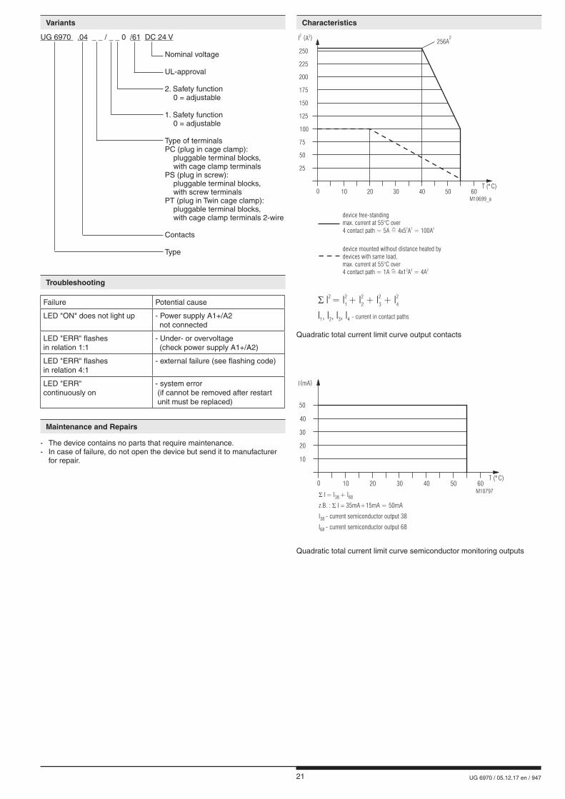
Quadratic total current limit curve output contacts
Quadratic total current limit curve semiconductor monitoring outputs
M10699_a
- current in contact pathsI , I , I , I1 2 3 4
� I = I + I + I + I2 2 2 2 2
1 2 3 4
25
I2
(A )2
75
100
125
50
0 10 20 30 40 6050T ( C)°
150
175
200
225
250
256A2
device mounted without distance heated bydevices with same load,max. current at over4 contact path = 1A = 4x1 A = 4A
55°C2 2 2^
device free-standingmax. current at 55°C over4 contact path = 5A = 4x5 A = 100A
2 2 2^
M10797
10
I(mA)
30
40
50
20
0 10 20 30 40 6050T ( C)°
� I = I + I38 68
z.B. : I 35mA+15mA = 50mA� �
I - current semiconductor output 3838
I - 6868 current semiconductor output
22 UG 6970 / 05.12.17 en / 947
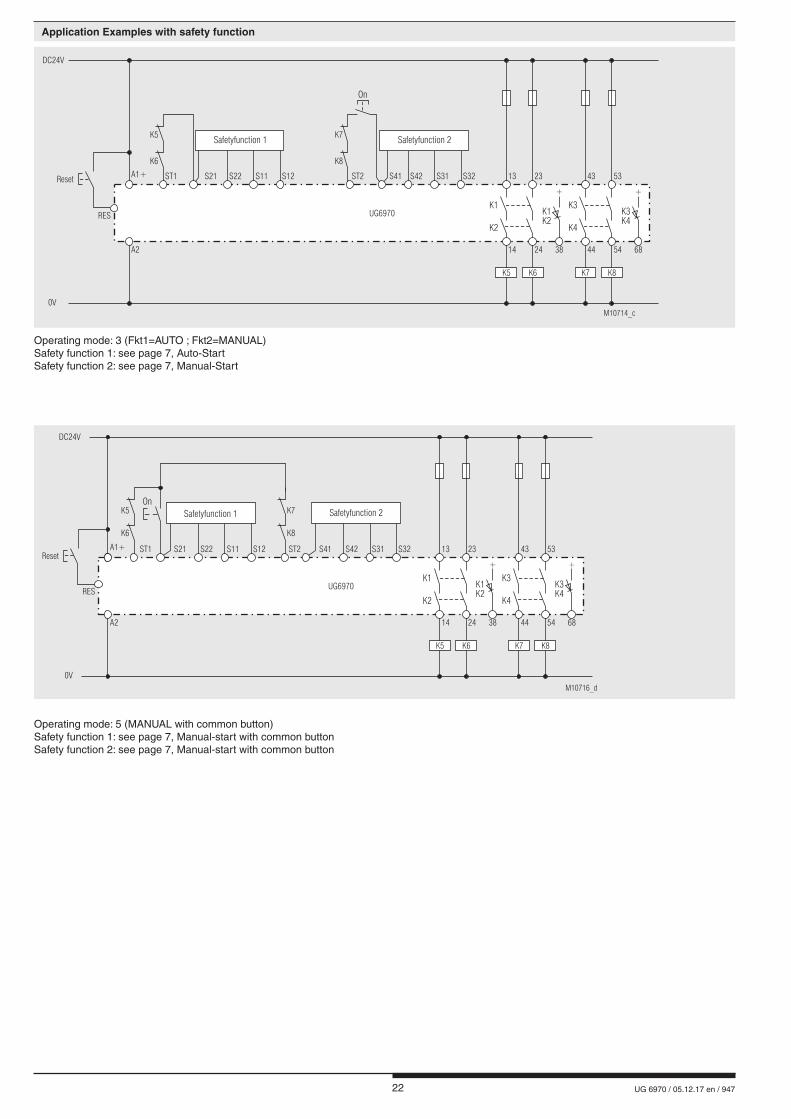
Operating mode: 3 (Fkt1=AUTO ; Fkt2=MANUAL)Safety function 1: see page 7, Auto-Start Safety function 2: see page 7, Manual-Start
Operating mode: 5 (MANUAL with common button)Safety function 1: see page 7, Manual-start with common buttonSafety function 2: see page 7, Manual-start with common button
M10714_c
DC24V
0V
A1+
A2
ST1
K6 K8
K5 K7
ST2 S42S41 S31 S32 13 4323 53
24 5438 6814 44
K1 K3K1 K3K2 K4
K2 K4
On
K5 K6 K7 K8
+ +
UG6970
S22S21 S11 S12
Safetyfunction 1 Safetyfunction 2
Reset
RES
M10716_d
DC24V
0V
A1+
A2
K6 K8
K5 K7
S41ST2ST1 13 23
24 38 6814
K1 K3K1 K3K2 K4
K2 K4
UG6970
K5 K6 K7 K8
+ +
On
S22 S31S21 S42S11 S32S12
Safetyfunction 1 Safetyfunction 2
Reset
RES
43 53
5444
Application Examples with safety function
23 UG 6970 / 05.12.17 en / 947
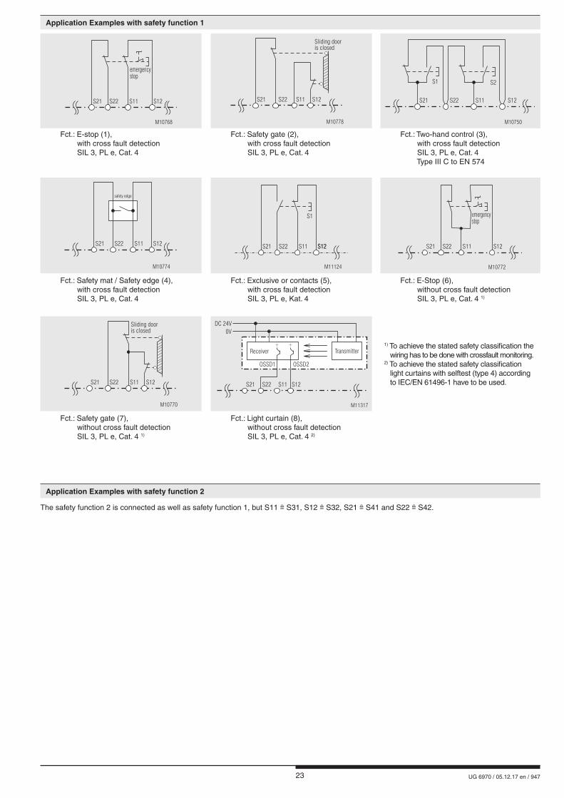
The safety function 2 is connected as well as safety function 1, but S11 S31, S12 S32, S21 S41 and S22 S42.
S22 S11 S12
M10768
emergencystop
S21 S21 S22 S11 S12
Sliding dooris closed
M10778
S1 S2
S22S21 S11 S12
M10750
Fct.: E-stop (1), with cross fault detection SIL 3, PL e, Cat. 4
Fct.: Safety gate (2), with cross fault detection SIL 3, PL e, Cat. 4
Fct.: Two-hand control (3), with cross fault detection SIL 3, PL e, Cat. 4 Type III C to EN 574
S21 S22 S11 S12
safety edge
M10774
S22 S11 S12S12
S1
M11124
S21 S22 S11 S12
M10772
emergencystop
S21
Fct.: Safety mat / Safety edge (4), with cross fault detection SIL 3, PL e, Cat. 4
Fct.: Exclusive or contacts (5), with cross fault detection SIL 3, PL e, Kat. 4
Fct.: E-Stop (6), without cross fault detection SIL 3, PL e, Cat. 4 1)
S21 S22 S11 S12
Sliding dooris closed
M10770
OSSD1 OSSD2
S22S21 S11 S12
TransmitterReceiver
DC 24V
0V
M11317
++ 1) To achieve the stated safety classification the wiring has to be done with crossfault monitoring.2) To achieve the stated safety classification light curtains with selftest (type 4) according to IEC/EN 61496-1 have to be used.
Fct.: Safety gate (7), without cross fault detection SIL 3, PL e, Cat. 4 1)
Fct.: Light curtain (8), without cross fault detection SIL 3, PL e, Cat. 4 2)
Application Examples with safety function 1
Application Examples with safety function 2

24 UG 6970 / 05.12.17 en / 947
E. DOLD & SÖHNE KG • D-78114 Furtwangene-mail: [email protected] • internet: http://www.dold.com
• PO Box 1251 • Telephone (+49) 77 23 / 654-0 • Telefax (+49) 77 23 / 654-356
25 UG 6970 / 05.12.17 fr / 947
Fiche Technique / Manuel d'utilisation FRANÇAIS
E. DOLD & SÖHNE KGB.P. 1251 • 78114 Furtwangen • AllemagneTél. +49 7723 6540 • Fax +49 7723 [email protected] • www.dold.com
Traduction de la notice originale
SAFEMASTER C Module de sécurité multifonctions UG 6970
0266691
26 UG 6970 / 05.12.17 fr / 947
Tables des matières
Explication des symboles et remarques ..........................................................................................................................27
Remarques ......................................................................................................................................................................27
Usage approprié ..............................................................................................................................................................27
Consignes de sécurité .....................................................................................................................................................27
Description du produit .....................................................................................................................................................29
Schéma ...........................................................................................................................................................................29
Borniers ...........................................................................................................................................................................29
Homologations et sigles ..................................................................................................................................................29
Utilisations .......................................................................................................................................................................29
Affichages ........................................................................................................................................................................29
Function Diagram ............................................................................................................................................................30
Fault Indication by Flashing Code ...................................................................................................................................30
Block Diagram .................................................................................................................................................................30
Remarques ......................................................................................................................................................................31
Commande potentiomètre ...............................................................................................................................................31
Caractéristiques techniques ............................................................................................................................................31
Caractéristiques techniques ............................................................................................................................................32
Données UL .....................................................................................................................................................................32
Versions standard ............................................................................................................................................................32
Variantes ..........................................................................................................................................................................33
Diagnostics des défauts ..................................................................................................................................................33
Entretien et remise en état ..............................................................................................................................................33
Courbes caractéristiques .................................................................................................................................................33
Exemples d'utilisation avec fonction de sécurité ..............................................................................................................34
Exemples d'utilisation avec fonction de sécurité 1 ...........................................................................................................35
Exemples d'utilisation avec fonction de sécurité 2 ...........................................................................................................35
Marquage et raccordements ............................................................................................................................................37
Dimensions (dimensions en mm) ....................................................................................................................................38
Montage / Démontage des borniers PS / PC / PT ...........................................................................................................38
Données techniques sécuritaires ....................................................................................................................................39
Déclaration de conformité européenne ...........................................................................................................................40
27 UG 6970 / 05.12.17 fr / 947
Consignes de sécurité
AVERTISSEMENT
Risque d'électrocution ! Danger de mort ou risque de blessure grave.• Assurez-vous que l'installation et l'appareil est et rese en l'état hors tension pendant l'installation électrique.• L'appareil peut uniquement être utilisé dans les cas d'application pré-
vus dans le mode d'emploi / la fiche technique. Les instructions de la documentation correspondante doivent être respectées. Les conditions ambiantes autorisées doivent être respectées.
• La protection de contact des éléments raccordés et l'isolation des câbles d'alimentation doivent être conçus conformément aux prescriptions du mode d'emploi/ fiche technique.
• Respecter les prescriptions de la VDE et les prescriptions locales, et tout particulièrement les mesures de sécurité.
AVERTISSEMENT
Risques d'incendie et autres risques thermiques ! Danger de mort, risque de blessure grave ou dégâts matériels. • L'appareil peut uniquement être utilisé dans les cas d'application prévus
dans le mode d'emploi / la fiche technique. Les instructions de la documen-tation correspondante doivent être respectées. Les conditions ambiantes autorisées doivent être respectées. Respectez tout particulièrement la courbe des seuils de courant.
• L'appareil peut uniquement être installé et mis en service par un personnel dûment qualifié et familier avec la présente documentation technique et avec les prescriptions en vigueur relatives à la sécurité du travail et à la préservation de l'environnement.
AVERTISSEMENT
Erreur de fonctionnement ! Danger de mort, risque de blessure grave ou dégâts matériels. • L'appareil peut uniquement être utilisé dans les cas d'application pré-
vus dans le mode d'emploi / la fiche technique. Les instructions de la documentation correspondante doivent être respectées. Les conditions ambiantes autorisées doivent être respectées.
• L'appareil peut uniquement être installé et mis en service par un personnel dûment qualifié et familier avec la présente documentation technique et avec les prescriptions en vigueur relatives à la sécurité du travail et à la préservation de l'environnement.
• Le relais doit être monté en armoire ayant un indice de protection au moins IP 54; la poussière et l'humidité pouvant entraîner des disfonctionnements.
AVERTISSEMENT
Erreur d'installation ! Danger de mort, risque de blessure grave ou dégâts matériels. • Veillez à protéger suffisamment les contacts de sortie de charges ca-
pacitives et inductives.
! Attention! • La fonction de sécurité doit être activée lors de la mise en service.• AUTOMATISCHER START ! Selon IEC/EN 60 204-1 Art. 9.2.5.4.2 il est interdit d’effectuer un re- démarrage automatique après un Arrêt d’urgence. Losqu’un démarrage automatique est toutefois demandé, il est necéssaire de assurer qu’une commande prioritaire effectue le blocage après une action d’arrêt d’urgence.• L'ouverture de l'appareil ou des transformations non autorisées annulent la garantie.
DANGER
DANGER: Indique que la mort ou des blessures graves vont survenir en
cas de non respect des précautions demandées.
AVERTISSEMENT
AVERTISSEMENT: Indique que la mort ou des blessures graves peuvent survenir
si les précautions appropriées ne sont pas prises.
PRUDENCE
PRUDENCE: Signifie qu'une blessures légère peut survenir si les précautions
appropriées ne sont pas prises.
! ATTENTION:
Met en garde contre les actions qui peuvent causer des dommages au materiel Software ou hardware suite à un mauvais fonctionne-ment de l'appareil ou de l'environnement de l'appareil.
nfo INFO:
Concerne les informations qui vous sont mises à disposition pour le meilleur usage du produit.
Explication des symboles et remarques
L'installation ne doit être effectuée que par un electricien qualifié
Ne pas jeter aux ordures ménagères! L'appareil doit être éliminé conformément aux prescriptions et
directives nationales en vigueur.
Pour vous aider à comprendre et trouver des passages et des notes de texte spécifiques dans les instructions d'utilisation, nous avons marquées les informations importantes avec des symboles.
Avant l'installation, la mise en service ou l'entretien de cet appareil, on doit avoir lu et compris ce manuel d'utilisation.
Usage approprié
Le produit décrit ici a été développé pour remplir les fonctions de sécurité en tant qu'élément d'une installation globale ou d'une machine. Un systè-me de sécurité complet inclut habituellement des détecteurs ainsi que des modules d'évaluation, de signalisation et de logique aptes à déclencher des coupures de courant sûres. La responsabilité d'assurer la fiabilité de l'ensemble de la fonction incombe au fabricant de l'installation ou de la ma-chine. DOLD n'est pas en mesure de garantir toutes les caractéristiques d'une installation ou d'une machine dont la conception lui échappe. C'est à l'utilisateur de valider la conception globale du système auquel ce relais est connecté. DOLD ne prend en charge aucune responsabilité quant aux recommandations qui sont données ou impliquées par la description sui-vante. Sur la base du présent manuel d'utilisation, on ne pourra déduire aucune modification concernant les conditions générales de livraison de DOLD, les exigences de garantie ou de responsabilité.
Remarques
Le UG 6970 permet l'enclenchement et le déclenchement d’un circuit électrique sécuritaire. ll peut être utilisé pour la protection de personnes et de machines en combinaison avec des BP d’arrêt d’urgence, portes de sécurité, et interprétation des barrières lumineuses avec autotest (Typ 4) selon IEC/EN 61496-1,bimanuelles pour presses métalliques ainsi que pour des machines avec des fonctions de fermeture dangereuses (Type IIIC selon EN574) pour des tapis ou rebords sensibles sécuritaires. Le courant de boucle du UG 6970 est limité à 15mA, afin d'éviter une dé-terioration des tapis et bordures sensibles en cas de court-circuits. En cas d'emploi approprié et d'observation de ces instructions, on ne connaît aucun risque résiduel. Dans le cas contraire, on encourt des riques de dommages corporels et matériels.
Stockage pour référence future

28 UG 6970 / 05.12.17 fr / 947
29 UG 6970 / 05.12.17 fr / 947
Canada / USA
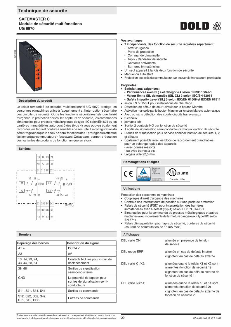
Le relais temporisé de sécurité multifonctionnel UG 6970 protège les personnes et machines grâce à l'acquittement et l'interruption sécuritaire des circuits de sécurité. Outre les fonctions sécuritaires tels que l'arrêt d'urgence, la protection portes, les capteurs de sécurité, les commandes bimanuelles pour presses métallurgiques de type IIIC selon EN 574 ou les barrières immatérièlles auto-contrôlées (type 4) vous pouvez également raccorder vos tapis et bordures sensibles de sécurité. La configuration du démarrage ainsi que le choix de deux fonctions des 5 préréglées s'effectue facilement par commutateur en face avant. Cet appareil permet la réduction des variantes de produits de fonction unique en stock.
Technique de sécurité
SAFEMASTER CModule de sécurité multifonctionsUG 6970
Description du produit
Schéma
Borniers
Homologations et sigles
Utilisations
Affichages
DEL verte ON: allumée en présence de tension de service
DEL rouge ERR: allumée en cas de défauts interne clignotent en cas de défauts externe
DEL verte K1/K2: allumées quand le relais K1 et K2 sont alimentés (fonction de sécurité 1) clignotent en cas de défauts externe de fonction de sécurité 1
DEL verte K3/K4: allumées quand le relais K3 et K4 sont alimentés (fonction de sécurité 2) clignotent en cas de défauts externe de fonction de sécurité 2
Vos avantages• 2 indépendants, des fonction de sécurité réglables séparément: - Arrêt d'urgence - Porte de protection - Commande bimanuelle - Tapis / Bandeaux de sécurité - Contacts antivalents - Barrières immatérielles• Un seul appareil à la fois deux fonction de sécurité• Manuel ou auto start• Protection des clés du commutateur par couvercle transparent plombable
Propriétés• Satisfait aux exigences: - Performance Level (PL) e et Catégorie 4 selon EN ISO 13849-1 - Valeur limite SIL demandée (SIL CL) 3 selon IEC/EN 62061 - Safety Integrity Level (SIL) 3 selon IEC/EN 61508 et IEC/EN 61511• selon EN 50156-1 pour installations de chauffage• Détection de défaut de court-circuit sur le bouton Marche• Activation manuelle par le bouton Marche ou fonction Marche automatique• Avec ou sans détection des courts-circuits transversaux• 2-canaux• contacts liés• Sortie: 2 contacts NO par fonction de sécurité• 1 sortie de signalisation semi-conducteurs chacun fonction de sécurité• Diodes de visualisation pour service nominal fonction de sécurité 1, 2 et défauts• Également possible avec les blocs de raccordement branchables pour un échange rapide des appareils - avec bornes ressorts - ou avec bornes à vis• Largeur utile 22,5 mm
Protection des personnes et machines• Couplages d'arrêt d'urgence des machines• Contrôle des interrupteurs de position sur une porte de protection• Relais de sécurité (FSD) pour interprétation des barrières immatérielles avec autotest (Typ 4) selon IEC/EN 61496-1• Bimanuelles pour la commande de presses métallurgiques et autres machines avec mouvements de fermeture dangereux. (Type IIIC selon EN 574) • Relais d'interprétation pour tapis de sécurité, bordures de sécurité (courant de commutation de 15 mA max.)
Repérage des bornes Description du signal
A1 + DC 24 V
A2 0V
13, 14, 23, 24,43, 44, 53, 54
Contacts NO liés pour circuit de déclenchement
38, 68 Sorties de signalisation semi-conducteurs
GND Le potentiel de rapport pour sorties de signalisation semi-conducteurs
S11, S21, S31, S41 Sorties de commande
S12, S22, S32, S42, ST1, ST2, RES
Entrées de commande
S12
A2
14
44
GND
S32
S11
A1+
13
43
RES
S31
S21
ST1
23
53
ST2
S41
S22
38
24
54
68
S42M10501_a
13 43
K1 K3
K2 K4
23 53
14 4424 54
K3/K4K1/K2
++
6838
0272
286
Toutes les caractéristiques données dans cette notice correspondent à l’édition en cours. Nous nousréservons le droit de procéder à tout moment aux améliorations ou modifications techniques nécessaires.
30 UG 6970 / 05.12.17 fr / 947
Fault Indication by Flashing Code
Function Diagram
Block Diagram
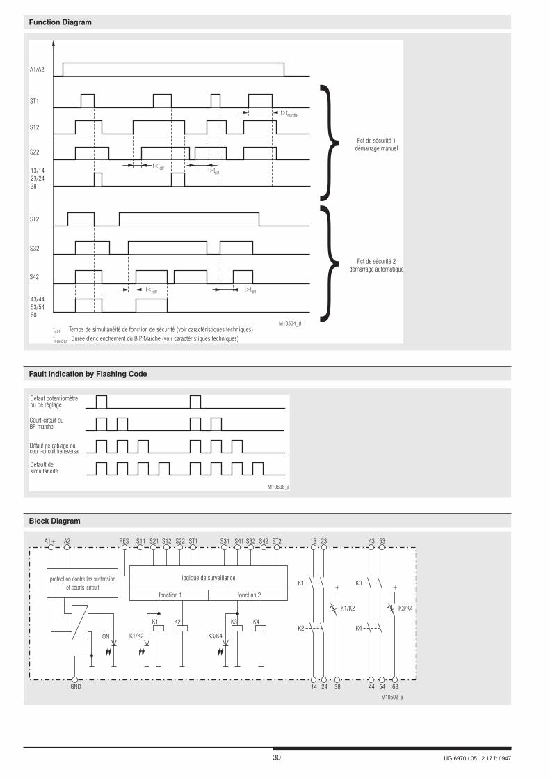
Défault desimultanéité
Défaut potentiomètreou de règlage
Court-circuit duBP marche
Défaut de cablage oucourt-circuit transversal
M10698_a
M10502_a
A1+ A2 S11RES S31S12 S32ST1 ST2S21 S41S22 S42 23 53
+ +
13 43
GND 24 38 685414 44
K1 K3K2 K4
K1/K2 K3/K4K2 K4
K1 K3
K3/K4K1/K2
ON
protection contre les surtension
et courts-circuit
logique de surveillance
fonction 1 fonction 2
Fct de sécurité 2démarrage automatique
Fct de sécurité 1démarrage manuel
M10504_d
S22
S12
ST1
t>tmarche
t>tdiff
t>tdifft<tdiff
t<tdiff
A1/A2
13/1423/2438
ST2
S42
S32
43/4453/5468
t : Temps de simultanéité de fonction de sécurité (voir caractéristiques techniques)
t : Durée d'enclenchement du B.P. Marche (voir caractéristiques techniques)diff
marche
31 UG 6970 / 05.12.17 fr / 947
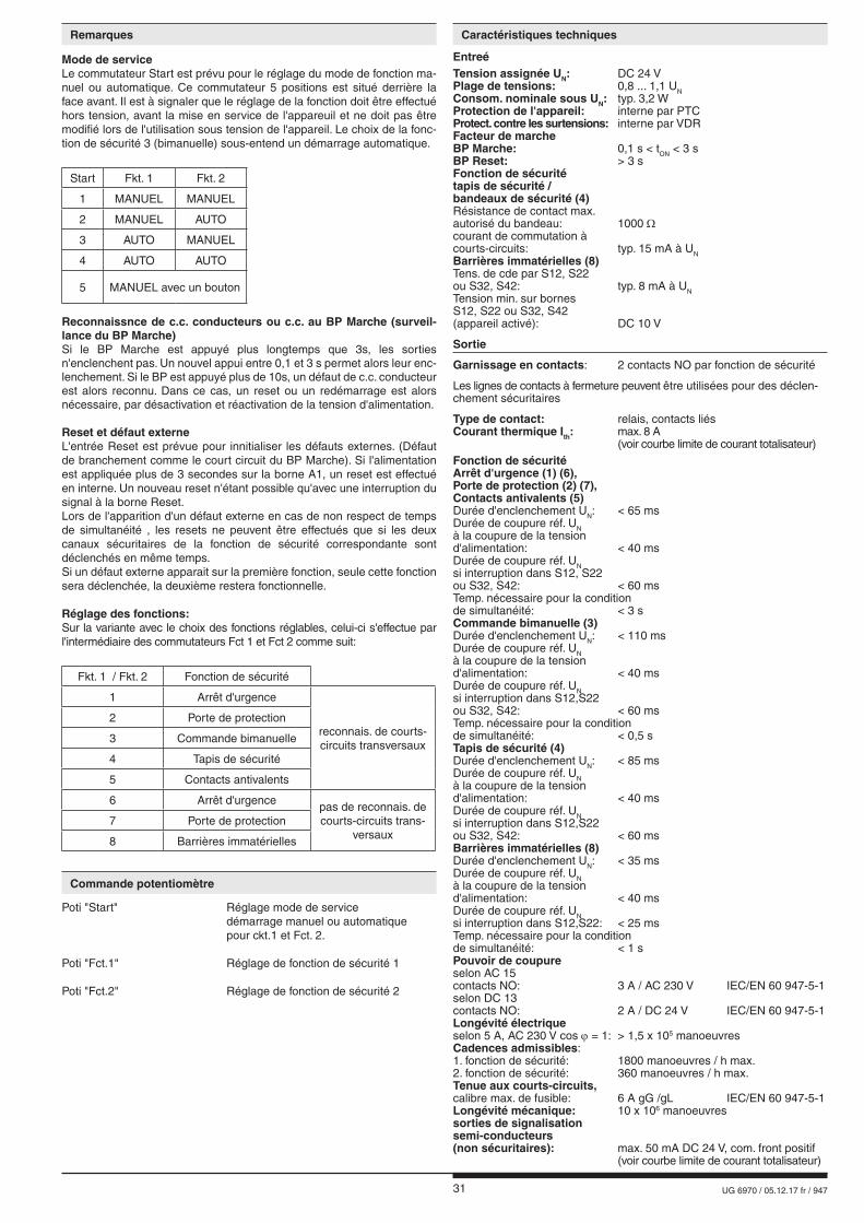
Entreé Tension assignée UN: DC 24 VPlage de tensions: 0,8 ... 1,1 UNConsom. nominale sous UN: typ. 3,2 WProtection de l'appareil: interne par PTCProtect. contre les surtensions: interne par VDRFacteur de marcheBP Marche: 0,1 s < tON < 3 sBP Reset: > 3 sFonction de sécurité tapis de sécurité / bandeaux de sécurité (4)Résistance de contact max. autorisé du bandeau: 1000 Ωcourant de commutation à courts-circuits: typ. 15 mA à UNBarrières immatérielles (8)Tens. de cde par S12, S22ou S32, S42: typ. 8 mA à UNTension min. sur bornes S12, S22 ou S32, S42(appareil activé): DC 10 V
Sortie
Garnissage en contacts: 2 contacts NO par fonction de sécurité
Les lignes de contacts à fermeture peuvent être utilisées pour des déclen-chement sécuritaires
Type de contact: relais, contacts liésCourant thermique Ith: max. 8 A (voir courbe limite de courant totalisateur)Fonction de sécuritéArrêt d'urgence (1) (6), Porte de protection (2) (7),Contacts antivalents (5)Durée d'enclenchement UN: < 65 msDurée de coupure réf. UN à la coupure de la tension d'alimentation: < 40 msDurée de coupure réf. UN si interruption dans S12, S22ou S32, S42: < 60 msTemp. nécessaire pour la conditionde simultanéité: < 3 sCommande bimanuelle (3)Durée d'enclenchement UN: < 110 msDurée de coupure réf. UN à la coupure de la tension d'alimentation: < 40 msDurée de coupure réf. UN si interruption dans S12,S22ou S32, S42: < 60 msTemp. nécessaire pour la conditionde simultanéité: < 0,5 s Tapis de sécurité (4)Durée d'enclenchement UN: < 85 msDurée de coupure réf. UN à la coupure de la tension d'alimentation: < 40 msDurée de coupure réf. UN si interruption dans S12,S22ou S32, S42: < 60 msBarrières immatérielles (8)Durée d'enclenchement UN: < 35 msDurée de coupure réf. UN à la coupure de la tension d'alimentation: < 40 msDurée de coupure réf. UN si interruption dans S12,S22: < 25 msTemp. nécessaire pour la conditionde simultanéité: < 1 sPouvoir de coupureselon AC 15contacts NO: 3 A / AC 230 V IEC/EN 60 947-5-1 selon DC 13contacts NO: 2 A / DC 24 V IEC/EN 60 947-5-1Longévité électriqueselon 5 A, AC 230 V cos j = 1: > 1,5 x 10⁵ manoeuvresCadences admissibles: 1. fonction de sécurité: 1800 manoeuvres / h max. 2. fonction de sécurité: 360 manoeuvres / h max. Tenue aux courts-circuits,calibre max. de fusible: 6 A gG /gL IEC/EN 60 947-5-1Longévité mécanique: 10 x 106 manoeuvressorties de signalisation semi-conducteurs(non sécuritaires): max. 50 mA DC 24 V, com. front positif (voir courbe limite de courant totalisateur)
Remarques Caractéristiques techniques
Mode de serviceLe commutateur Start est prévu pour le réglage du mode de fonction ma-nuel ou automatique. Ce commutateur 5 positions est situé derrière la face avant. Il est à signaler que le réglage de la fonction doit être effectué hors tension, avant la mise en service de l'appareuil et ne doit pas être modifié lors de l'utilisation sous tension de l'appareil. Le choix de la fonc-tion de sécurité 3 (bimanuelle) sous-entend un démarrage automatique.
Start Fkt. 1 Fkt. 2
1 MANUEL MANUEL
2 MANUEL AUTO
3 AUTO MANUEL
4 AUTO AUTO
5 MANUEL avec un bouton
Reconnaissnce de c.c. conducteurs ou c.c. au BP Marche (surveil-lance du BP Marche)Si le BP Marche est appuyé plus longtemps que 3s, les sorties n'enclenchent pas. Un nouvel appui entre 0,1 et 3 s permet alors leur enc-lenchement. Si le BP est appuyé plus de 10s, un défaut de c.c. conducteur est alors reconnu. Dans ce cas, un reset ou un redémarrage est alors nécessaire, par désactivation et réactivation de la tension d'alimentation.
Reset et défaut externeL'entrée Reset est prévue pour innitialiser les défauts externes. (Défaut de branchement comme le court circuit du BP Marche). Si l'alimentation est appliquée plus de 3 secondes sur la borne A1, un reset est effectué en interne. Un nouveau reset n'étant possible qu'avec une interruption du signal à la borne Reset.Lors de l'apparition d'un défaut externe en cas de non respect de temps de simultanéité , les resets ne peuvent être effectués que si les deux canaux sécuritaires de la fonction de sécurité correspondante sont déclenchés en même temps.Si un défaut externe apparait sur la première fonction, seule cette fonction sera déclenchée, la deuxième restera fonctionnelle. Réglage des fonctions:Sur la variante avec le choix des fonctions réglables, celui-ci s'effectue par l'intermédiaire des commutateurs Fct 1 et Fct 2 comme suit:
Fkt. 1 / Fkt. 2 Fonction de sécurité
1 Arrêt d'urgence
reconnais. de courts-circuits transversaux
2 Porte de protection
3 Commande bimanuelle
4 Tapis de sécurité
5 Contacts antivalents
6 Arrêt d'urgence pas de reconnais. de courts-circuits trans-
versaux7 Porte de protection
8 Barrières immatérielles
Commande potentiomètre
Poti "Start" Réglage mode de service démarrage manuel ou automatique pour ckt.1 et Fct. 2.
Poti "Fct.1" Réglage de fonction de sécurité 1
Poti "Fct.2" Réglage de fonction de sécurité 2
32 UG 6970 / 05.12.17 fr / 947
UG 6970.04PS/ 61 DC24V Référence: 0065426• 1. fonction de sécurité: réglable• 2. fonction de sécurité: réglable• Sortie: 2 contacts NO par fonction de sécurité • Tension nominal: DC 24 V• Largeur utile: 22,5 mm
Les fonctions sécuritaires de l‘appareil n‘ont pas été analysées par UL. Le sujet de l‘homologation est la conformité aux standards UL 508, „ general use applications“
Température ambiante: - 15 … + 55 °C
Pouvoir de coupure: Température ambiante 55°C Pilot duty B300, Q300 5 A 250 Vac Resistive or G.P. 5 A 24 Vdc Resistive
Température ambiante 40°C: Pilot duty B300, Q300 8 A 250 Vac Resistive or G.P. 8 A 24 Vdc G.P. Connectique: uniquement pour 60°/75°C conducteur cuivreBorne PS: AWG 28 - 12 Sol/Str Torque 0.5 NmBorne PC: AWG 24 - 12 Sol/StrBorne PT: AWG 24 - 16 Sol/Str
nfo Les valeurs techniques qui ne sont pas spécifiées ci-dessus
sont spécifiées dans les valeurs techniques générales.
Caractéristiques techniques Données UL
Versions standard
Caractéristiques générales
Type nominal de service: service permanentPlage de températuresopération: - 25 ... + 55 °C stockage: - 25 ... + 85 °C Altitude: < 2.000 mDistances dans l'airet lignes de fuiteCatégorie de surtension /degré de contamination: 4 kV / 2 IEC 60 664-1CEM IEC/EN 61 326-3-1, IEC/EN 62 061Antiparasitage: seuil classe B EN 55 011Degré de protectionboîtier: IP 40 IEC/EN 60 529bornes: IP 20 IEC/EN 60 529Boîtier: thermoplastique à comportement V0 selon UL Subject 94Résistance aux vibrations: amplitude 0,35 mm fréq. 10 ... 55 Hz IEC/EN 60 068-2-6Résistance climatique: 25 / 055 / 04 IEC/EN 60 068-1Repérage des bornes: EN 50 005Fixation des conducteurs: vis de serrage cruciformes imperdables ou bornes ressortsFixation instantanée: sur rail IEC/EN 60 715Poids net: env. 275 g
Dimensions largeur x hauteur x profondeur UG 6970 PS: 22,5 x 110 x 120,3 mmUG 6970PC, PT: 22,5 x 120 x 120,3 mm
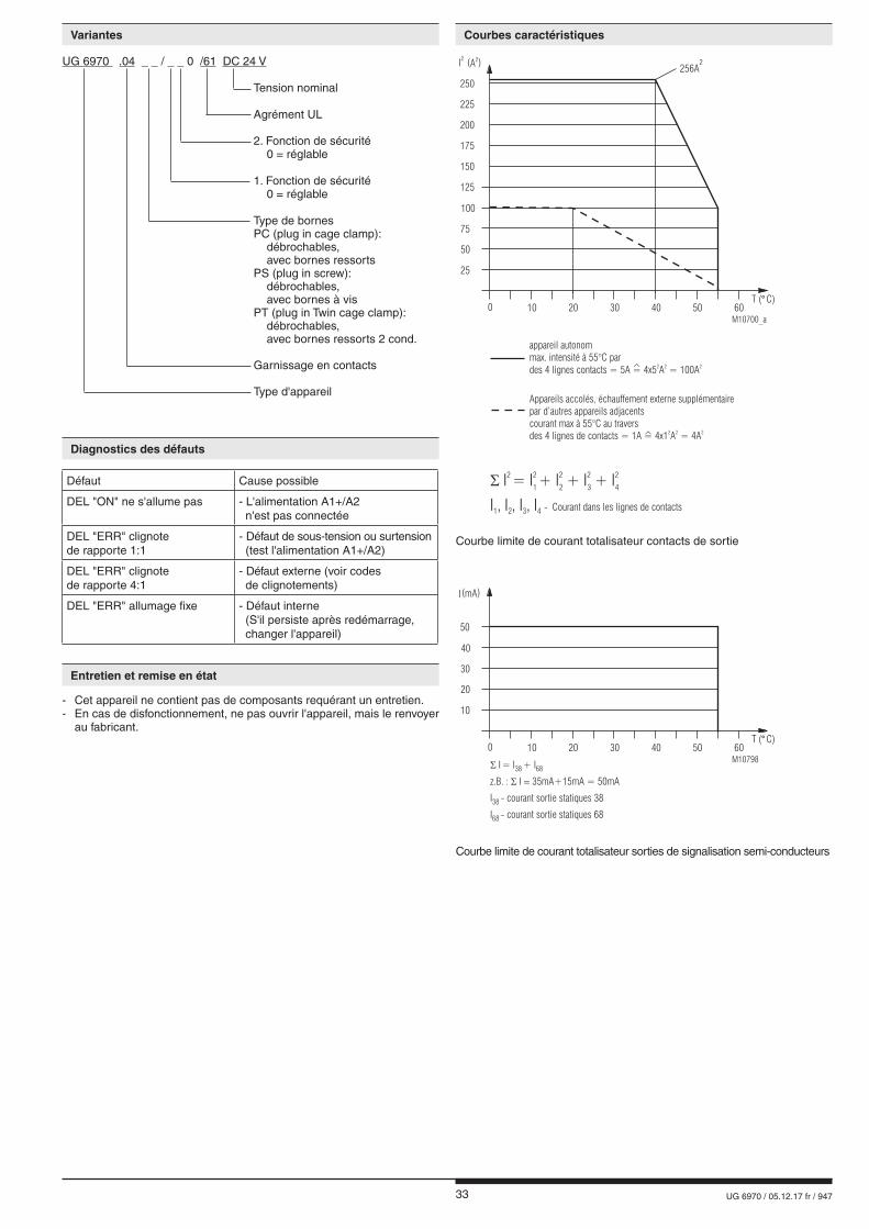
33 UG 6970 / 05.12.17 fr / 947
Variantes Courbes caractéristiques
- Cet appareil ne contient pas de composants requérant un entretien.- En cas de disfonctionnement, ne pas ouvrir l'appareil, mais le renvoyer au fabricant.
Défaut Cause possible
DEL "ON" ne s'allume pas - L'alimentation A1+/A2 n'est pas connectée
DEL "ERR" clignote de rapporte 1:1
- Défaut de sous-tension ou surtension (test l'alimentation A1+/A2)
DEL "ERR" clignote de rapporte 4:1
- Défaut externe (voir codes de clignotements)
DEL "ERR" allumage fixe - Défaut interne (S'il persiste après redémarrage, changer l'appareil)
Entretien et remise en état
Diagnostics des défauts
UG 6970 .04 _ _ / _ _ 0 /61 DC 24 V
Tension nominal
Agrément UL 2. Fonction de sécurité 0 = réglable 1. Fonction de sécurité 0 = réglable Type de bornes PC (plug in cage clamp): débrochables, avec bornes ressorts PS (plug in screw): débrochables, avec bornes à vis PT (plug in Twin cage clamp): débrochables, avec bornes ressorts 2 cond. Garnissage en contacts Type d'appareil
Courbe limite de courant totalisateur contacts de sortie
Courbe limite de courant totalisateur sorties de signalisation semi-conducteurs
M10798
10
I(mA)
30
40
50
20
0 10 20 30 40 6050T ( C)°
� I = I + I38 68
z.B. : I 35mA+15mA = 50mA� �
I - courant sortie statiques 3838
I - 6868 courant sortie statiques
M10700_a
- Courant dans les lignes de contactsI , I , I , I1 2 3 4
� I = I + I + I + I2 2 2 2 2
1 2 3 4
Appareils accolés, échauffement externe supplémentairepar d’autres appareils adjacentscourant max à 55°C au traversdes 4 lignes de contacts = 1A = 4x1 A = 4A
2 2 2^
appareil autonommax. intensité à 55°C pardes 4 lignes contacts = 5A = 4x5 A = 100A
2 2 2^
25
I2
(A )2
75
100
125
50
0 10 20 30 40 6050T ( C)°
150
175
200
225
250
256A2
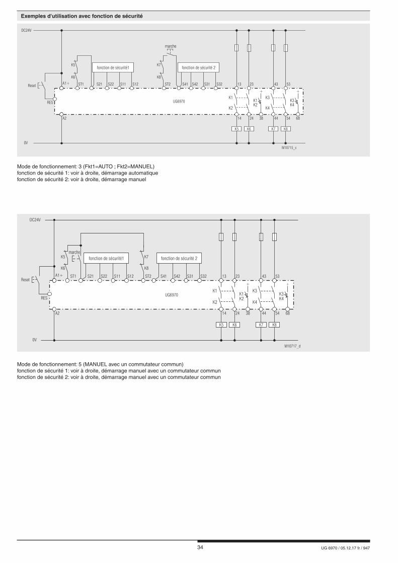
34 UG 6970 / 05.12.17 fr / 947
Exemples d'utilisation avec fonction de sécurité
M10715_c
DC24V
0V
A1+
A2
ST1
K6 K8
K5 K7
ST2 S42S41 S31 S32 13 4323 53
24 5438 6814 44
K1 K3K1 K3K2 K4
K2 K4
marche
K5 K6 K7 K8
+ +
UG6970
S22S21 S11 S12
fonction de sécurité1 fonction de sécurité 2
Reset
RES
Mode de fonctionnement: 5 (MANUEL avec un commutateur commun)fonction de sécurité 1: voir à droite, démarrage manuel avec un commutateur communfonction de sécurité 2: voir à droite, démarrage manuel avec un commutateur commun
M10717_d
marche
DC24V
0V
A1+
A2
K6 K8
K5 K7
S41ST2ST1 13 23
24 38 6814
K1 K3K1 K3K2 K4
K2 K4
UG6970
K5 K6 K7 K8
+ +
S22 S31S21 S42S11 S32S12
fonction de sécurité1 fonction de sécurité 2
Reset
RES
43 53
5444
Mode de fonctionnement: 3 (Fkt1=AUTO ; Fkt2=MANUEL)fonction de sécurité 1: voir à droite, démarrage automatiquefonction de sécurité 2: voir à droite, démarrage manuel
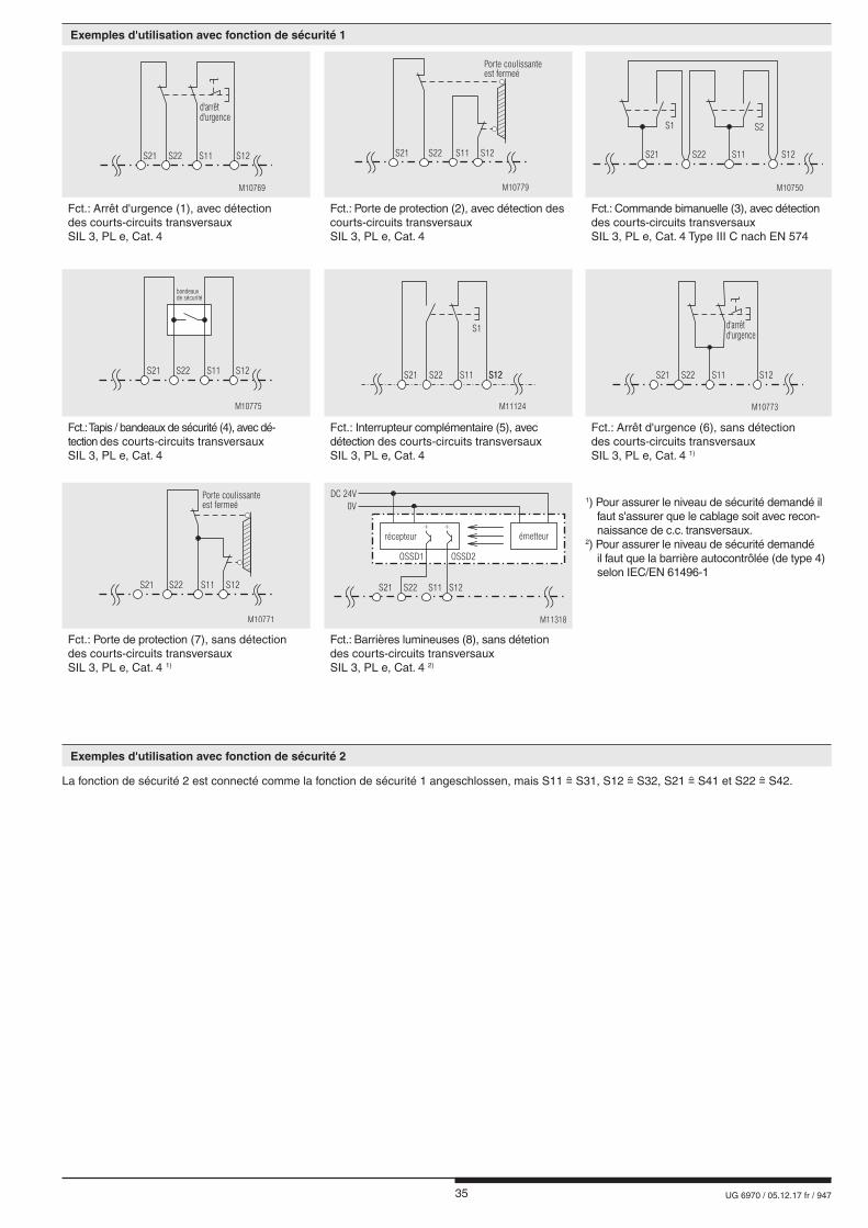
35 UG 6970 / 05.12.17 fr / 947
La fonction de sécurité 2 est connecté comme la fonction de sécurité 1 angeschlossen, mais S11 S31, S12 S32, S21 S41 et S22 S42.
Exemples d'utilisation avec fonction de sécurité 1
Exemples d'utilisation avec fonction de sécurité 2
S22 S11 S12
M10769
d'arrêtd'urgence
S21 S21 S22 S11 S12
Porte coulissanteest fermeé
M10779
S1 S2
S22S21 S11 S12
M10750
Fct.: Arrêt d'urgence (1), avec détection des courts-circuits transversaux SIL 3, PL e, Cat. 4
Fct.: Porte de protection (2), avec détection des courts-circuits transversaux SIL 3, PL e, Cat. 4
Fct.: Commande bimanuelle (3), avec détection des courts-circuits transversaux SIL 3, PL e, Cat. 4 Type III C nach EN 574
S21 S22 S11 S12
bandeauxde sécurité
M10775
S22 S11 S12S12
S1
M11124
S21 S22 S11 S12
M10773
d'arrêtd'urgence
S21
Fct.: Tapis / bandeaux de sécurité (4), avec dé-tection des courts-circuits transversaux SIL 3, PL e, Cat. 4
Fct.: Interrupteur complémentaire (5), avec détection des courts-circuits transversaux SIL 3, PL e, Cat. 4
Fct.: Arrêt d'urgence (6), sans détection des courts-circuits transversaux SIL 3, PL e, Cat. 4 1)
S21 S22 S11 S12
Porte coulissanteest fermeé
M10771
OSSD1 OSSD2
S22S21 S11 S12
DC 24V
0V
M11318
++
émetteurrécepteur
Fct.: Porte de protection (7), sans détection des courts-circuits transversaux SIL 3, PL e, Cat. 4 1)
Fct.: Barrières lumineuses (8), sans détetion des courts-circuits transversaux SIL 3, PL e, Cat. 4 2)
1) Pour assurer le niveau de sécurité demandé il faut s'assurer que le cablage soit avec recon- naissance de c.c. transversaux.2) Pour assurer le niveau de sécurité demandé il faut que la barrière autocontrôlée (de type 4) selon IEC/EN 61496-1

36 UG 6970 / 05.12.17 fr / 947
E. DOLD & SÖHNE KG • D-78114 Furtwangene-mail: [email protected] • internet: http://www.dold.com
• B.P. 1251 • Téléphone (+49) 77 23 / 654-0 • Téléfax (+49) 77 23 / 654-356
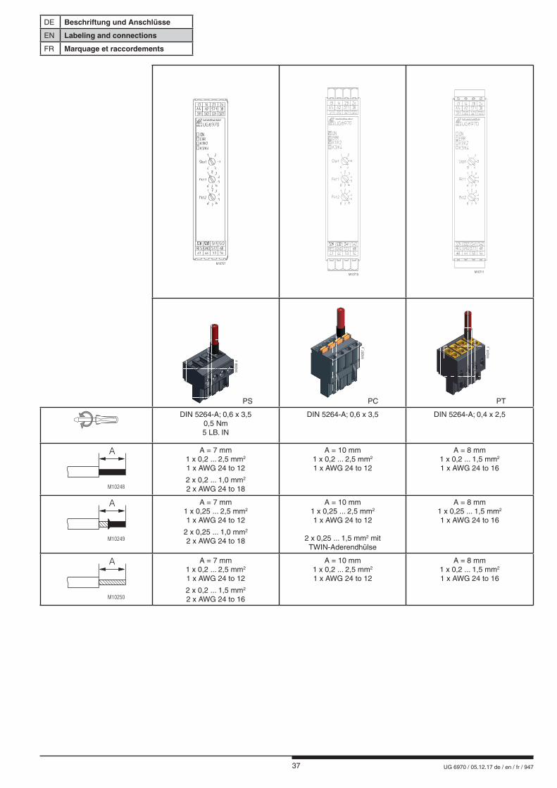
37 UG 6970 / 05.12.17 de / en / fr / 947
DE Beschriftung und Anschlüsse
EN Labeling and connections
FR Marquage et raccordements
M10707
M10710M10711
M42
88_
a
PS
M42
87_
a
PC
M43
44_
a
PT
DIN 5264-A; 0,6 x 3,50,5 Nm5 LB. IN
DIN 5264-A; 0,6 x 3,5 DIN 5264-A; 0,4 x 2,5
M10248
A A = 7 mm1 x 0,2 ... 2,5 mm2
1 x AWG 24 to 12
2 x 0,2 ... 1,0 mm2
2 x AWG 24 to 18
A = 10 mm1 x 0,2 ... 2,5 mm2
1 x AWG 24 to 12
A = 8 mm 1 x 0,2 ... 1,5 mm2 1 x AWG 24 to 16
M10249
A A = 7 mm1 x 0,25 ... 2,5 mm2
1 x AWG 24 to 12
2 x 0,25 ... 1,0 mm2
2 x AWG 24 to 18
A = 10 mm1 x 0,25 ... 2,5 mm2
1 x AWG 24 to 12
2 x 0,25 ... 1,5 mm2 mit TWIN-Aderendhülse
A = 8 mm 1 x 0,25 ... 1,5 mm2 1 x AWG 24 to 16
M10250
A A = 7 mm1 x 0,2 ... 2,5 mm2
1 x AWG 24 to 12
2 x 0,2 ... 1,5 mm2
2 x AWG 24 to 16
A = 10 mm1 x 0,2 ... 2,5 mm2
1 x AWG 24 to 12
A = 8 mm 1 x 0,2 ... 1,5 mm2 1 x AWG 24 to 16
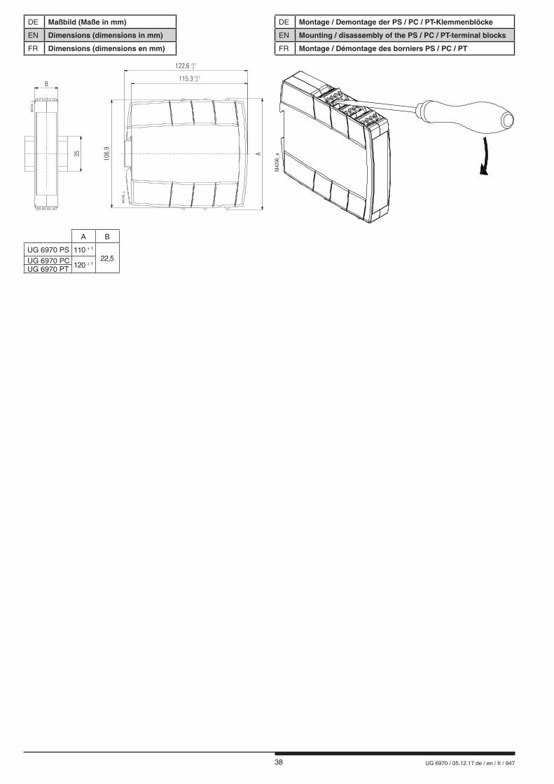
38 UG 6970 / 05.12.17 de / en / fr / 947
DE Maßbild (Maße in mm)
EN Dimensions (dimensions in mm)
FR Dimensions (dimensions en mm)
M43
45_a
M43
45_a
35115,3 - 0
0,7+
122,6 - 00,7+
B
A
106,
9
DE Montage / Demontage der PS / PC / PT-Klemmenblöcke
EN Mounting / disassembly of the PS / PC / PT-terminal blocks
FR Montage / Démontage des borniers PS / PC / PT
A B
UG 6970 PS 110 ± 1
22,5UG 6970 PC 120 ± 1
UG 6970 PT
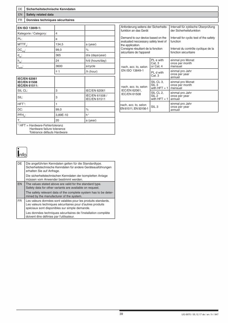
39 UG 6970 / 05.12.17 de / en / fr / 947
DE Sicherheitstechnische Kenndaten
EN Safety related data
FR Données techniques sécuritaires
nfo
DE Die angeführten Kenndaten gelten für die Standardtype. Sicherheitstechnische Kenndaten für andere Geräteausführungen erhalten Sie auf Anfrage.
Die sicherheitstechnischen Kenndaten der kompletten Anlagemüssen vom Anwender bestimmt werden.
EN The values stated above are valid for the standard type.Safety data for other variants are available on request.
The safety relevant data of the complete system has to be deter-mined by the manufacturer of the system.
FR Les valeurs données sont valables pour les produits standards.Les valeurs techniques sécuritaires pour d‘autres produits spéciaux sont disponibles sur simple demande.
Les données techniques sécuritaires de l'installation complète doivent être définies par l'utilisateur.
Anforderung seitens der Sicherheits- funktion an das Gerät
Intervall für zyklische Überprüfung der Sicherheitsfunktion
Demand to our device based on the evaluated neccessary safety level of the application.
Intervall for cyclic test of the safety function
Consigne résultant de la fonction sécuritaire de l'appareil
Interval du contrôle cyclique de la fonction sécuritaire
nach, acc. to, selonEN ISO 13849-1
PL e with Cat. 3 or Cat. 4
einmal pro Monatonce per monthmensuel
PL d with Cat. 3
einmal pro Jahronce per yearannuel
nach, acc. to, selon IEC/EN 62061, IEC/EN 61508
SIL CL 3,SIL 3with HFT = 1
einmal pro Monatonce per monthmensuel
SIL CL 2,SIL 2with HFT = 1
einmal pro Jahronce per yearannuel
nach, acc. to, selon EN 61511, EN 50156-1
SIL 3einmal pro Jahronce per yearannuel
EN ISO 13849-1:
Kategorie / Category: 4
PL: e
MTTFd: 134,5 a (year)
DCavg: 99,0 %
dop: 365 d/a (days/year)
hop: 24 h/d (hours/day)
tcycle: 3600 s/cycle
1 /h (hour)
IEC/EN 62061IEC/EN 61508IEC/EN 61511:
SIL CL: 3 IEC/EN 62061
SIL: 3 IEC/EN 61508 /IEC/EN 61511
HFT*): 1
DC: 99,0 %
PFHD: 3,89E-10 h-1
T1 20 a (year)*) HFT = Hardware-Fehlertoleranz Hardware failure tolerance Tolérance défauts Hardware
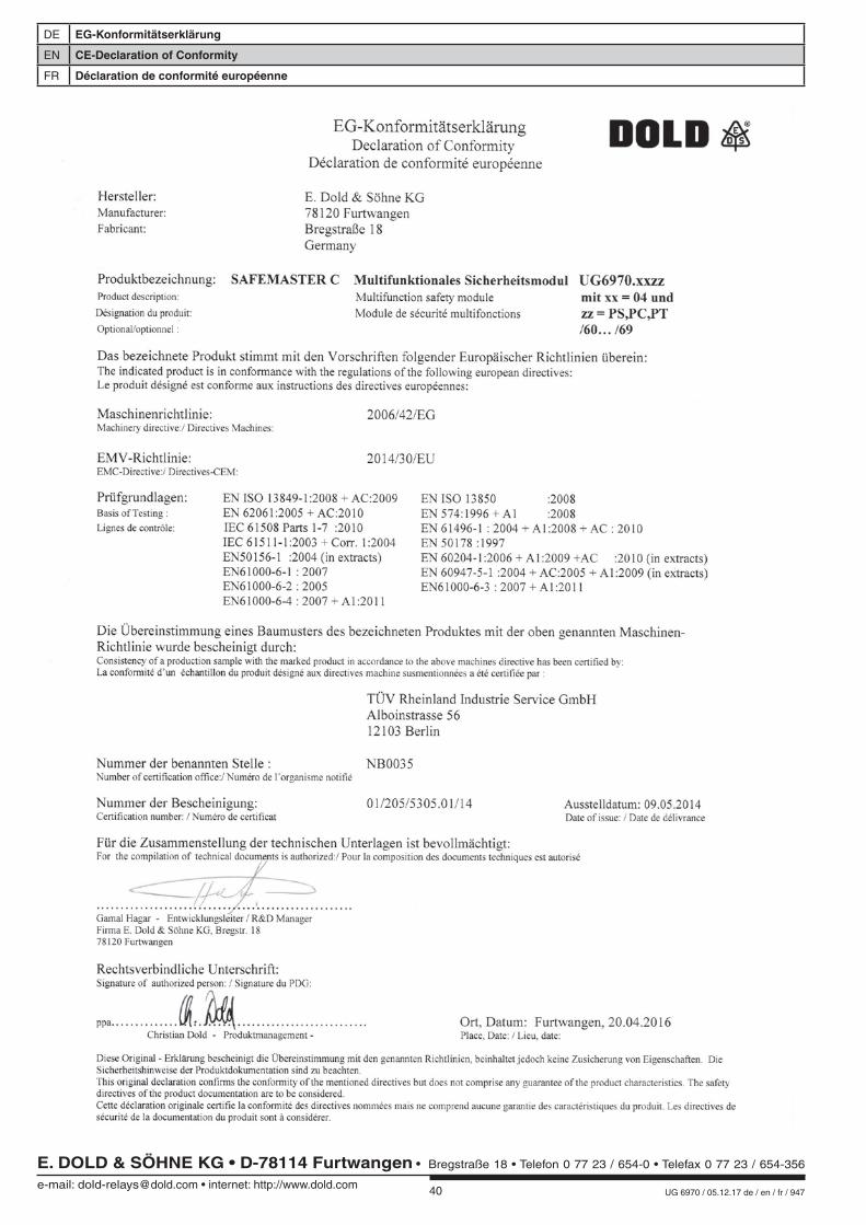
40 UG 6970 / 05.12.17 de / en / fr / 947
DE EG-Konformitätserklärung
EN CE-Declaration of Conformity
FR Déclaration de conformité européenne
E. DOLD & SÖHNE KG • D-78114 Furtwangene-mail: [email protected] • internet: http://www.dold.com
• Bregstraße 18 • Telefon 0 77 23 / 654-0 • Telefax 0 77 23 / 654-356