Multiline Pump Model 205 - SKF · 2.1A-18003-B98 LINCOLN GmbH • Postfach 1263 • D-69183...
29
2.1A-18003-B98 LINCOLN GmbH • Postfach 1263 • D-69183 Walldorf • Tel +49 (6227) 33-0 • Fax +49 (6227) 33-259 • Tx 466088 Owner’s Manual Multiline Pump Model 205 Page 1 of 29 Subject to change without notes Multiline Pump Model 205 5017a97
Transcript of Multiline Pump Model 205 - SKF · 2.1A-18003-B98 LINCOLN GmbH • Postfach 1263 • D-69183...
2.1A-18003-B98
LINCOLN GmbH • Postfach 1263 • D-69183 Walldorf • Tel +49 (6227) 33-0 • Fax +49 (6227) 33-259 • Tx 466088
Owner’s ManualMultiline Pump Model 205
Page 1 of 29Sub
ject
to c
hang
e w
ithou
t not
es
Multiline Pump Model 205
5017a97
LINCOLN GmbH • Postfach 1263 • D-69183 Walldorf • Tel +49 (6227) 33-0 • Fax +49 (6227) 33-259 • Tx 466088
2.1A-18003-B98
Page 2 of 29 Sub
ject
to c
hang
e w
ithou
t not
es
Owner’s ManualMultiline Pump Model 205
TABLE OF CONTENTS
Title ........................................................................ Page
Safety instructions .......................................................... 3Appropriate use ................................................................. 4Description ....................................................................... 5Identification chart ............................................................. 5General .............................................................................. 6Operation ........................................................................... 6Operation of the pump element ......................................... 7Erection and installation ................................................ 8Erection of the pump ......................................................... 8Electric connection ............................................................ 8Operating instructions .................................................... 8Commissioning .................................................................. 8
• The Operating Instructions- contain important information for the safe, correct and
economic operation of the pump/lubrication system. Theirobservance will help avoid hazards,
- reduce repair costs and downtime,- increase the reliability and prolong the service life of the
pump/lubrication system.- must be supplemented by the respective national regulations
concerning the prevention of accidents and protection of theenvironment.
Preface to the Owner’s Manual
• The Owner’s Manual
- is intended to familiarize the user with the pump/lubricationsystem and to enable him/her to use it adequately.
- must always be available on the site where the pump/lubrication system is in operation.
- must be read and used by all persons who are charged withworking with the pump/lubrication system, e.g.
• Operation , including adjustment, troubleshooting duringoperation, elimination of production waste, maintenance,disposal of process materials
• Maintenance (inspection, repairs) and/or• Transport
• Persons who do not have a good command of the Englishlanguage must be informed by the user of the pump/lubrication system on the contents of the Owner’s Manual,particularly the Safety Instructions, before they carry outthe work.
Title ........................................................................ Page
Commissioning when grease is dispensed .......................8Commissioning when fluid lubricantsare dispensed ..................................................................10Maintenance and repair ................................................ 11Assembly and disassembly of pump elements ............... 11Troubleshooting ............................................................12Technical data ................................................................13Electric equipment ...........................................................14Component parts of the pump 205 ..............................14Annex: Dimensioned drawings ....................................26Motor data sheet ..............................................................26Sensor data sheet ...........................................................27Manufacturer’s declaration ..........................................28
2.1A-18003-B98
LINCOLN GmbH • Postfach 1263 • D-69183 Walldorf • Tel +49 (6227) 33-0 • Fax +49 (6227) 33-259 • Tx 466088
Owner’s ManualMultiline Pump Model 205
Page 3 of 29Sub
ject
to c
hang
e w
ithou
t not
es
• The Operating Instructions include general instructions whichmust be followed when a pump/lubricating unit is installed,operated or serviced. Therefore, it is absolutely necessary forthe fitter and specialist/user to read the Operating Instruc-tions before a unit is installed and put into operation. TheOperating Instructions must always be available on the sitewhere the machine/system is installed.
• All general safety instructions contained in this main chapteron safety must be observed as well as all special safetyinstructions given in other main chapters.
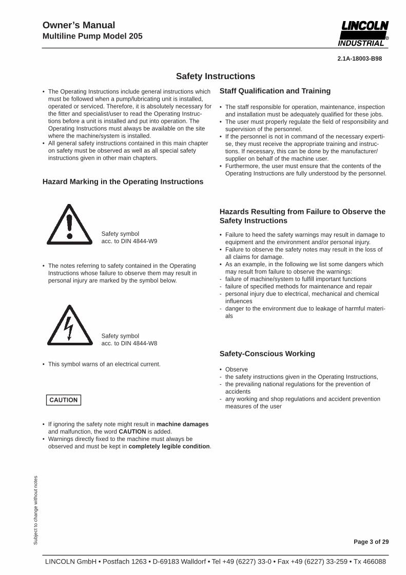
Safety Instructions
Hazard Marking in the Operating Instructions
• The staff responsible for operation, maintenance, inspectionand installation must be adequately qualified for these jobs.
• The user must properly regulate the field of responsibility andsupervision of the personnel.
• If the personnel is not in command of the necessary experti-se, they must receive the appropriate training and instruc-tions. If necessary, this can be done by the manufacturer/supplier on behalf of the machine user.
• Furthermore, the user must ensure that the contents of theOperating Instructions are fully understood by the personnel.
Safety symbolacc. to DIN 4844-W9
• The notes referring to safety contained in the OperatingInstructions whose failure to observe them may result inpersonal injury are marked by the symbol below.
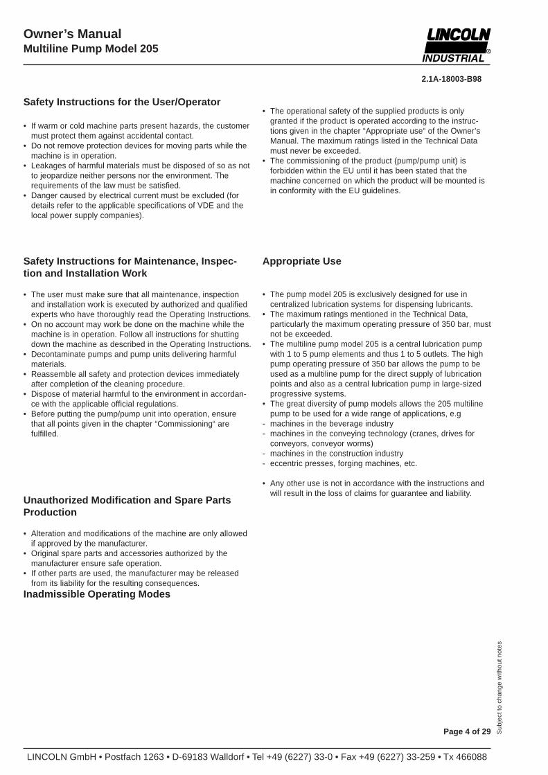
• This symbol warns of an electrical current.
• If ignoring the safety note might result in machine damagesand malfunction, the word CAUTION is added.
• Warnings directly fixed to the machine must always beobserved and must be kept in completely legible condition .
Safety symbolacc. to DIN 4844-W8
Hazards Resulting from Failure to Observe theSafety Instructions
• Failure to heed the safety warnings may result in damage toequipment and the environment and/or personal injury.
• Failure to observe the safety notes may result in the loss ofall claims for damage.
• As an example, in the following we list some dangers whichmay result from failure to observe the warnings:
- failure of machine/system to fulfill important functions- failure of specified methods for maintenance and repair- personal injury due to electrical, mechanical and chemical
influences- danger to the environment due to leakage of harmful materi-
als
Safety-Conscious Working
• Observe- the safety instructions given in the Operating Instructions,- the prevailing national regulations for the prevention of
accidents- any working and shop regulations and accident prevention
measures of the user
Staff Qualification and Training
CAUTION
LINCOLN GmbH • Postfach 1263 • D-69183 Walldorf • Tel +49 (6227) 33-0 • Fax +49 (6227) 33-259 • Tx 466088
2.1A-18003-B98
Page 4 of 29 Sub
ject
to c
hang
e w
ithou
t not
es
Owner’s ManualMultiline Pump Model 205
Safety Instructions for the User/Operator
• If warm or cold machine parts present hazards, the customermust protect them against accidental contact.
• Do not remove protection devices for moving parts while themachine is in operation.
• Leakages of harmful materials must be disposed of so as notto jeopardize neither persons nor the environment. Therequirements of the law must be satisfied.
• Danger caused by electrical current must be excluded (fordetails refer to the applicable specifications of VDE and thelocal power supply companies).
Safety Instructions for Maintenance, Inspec-tion and Installation Work
• The user must make sure that all maintenance, inspectionand installation work is executed by authorized and qualifiedexperts who have thoroughly read the Operating Instructions.
• On no account may work be done on the machine while themachine is in operation. Follow all instructions for shuttingdown the machine as described in the Operating Instructions.
• Decontaminate pumps and pump units delivering harmfulmaterials.
• Reassemble all safety and protection devices immediatelyafter completion of the cleaning procedure.
• Dispose of material harmful to the environment in accordan-ce with the applicable official regulations.
• Before putting the pump/pump unit into operation, ensurethat all points given in the chapter “Commissioning“ arefulfilled.
Appropriate Use
• The pump model 205 is exclusively designed for use incentralized lubrication systems for dispensing lubricants.
• The maximum ratings mentioned in the Technical Data,particularly the maximum operating pressure of 350 bar, mustnot be exceeded.
• The multiline pump model 205 is a central lubrication pumpwith 1 to 5 pump elements and thus 1 to 5 outlets. The highpump operating pressure of 350 bar allows the pump to beused as a multiline pump for the direct supply of lubricationpoints and also as a central lubrication pump in large-sizedprogressive systems.
• The great diversity of pump models allows the 205 multilinepump to be used for a wide range of applications, e.g
- machines in the beverage industry- machines in the conveying technology (cranes, drives for
conveyors, conveyor worms)- machines in the construction industry- eccentric presses, forging machines, etc.
• Any other use is not in accordance with the instructions andwill result in the loss of claims for guarantee and liability.
Unauthorized Modification and Spare PartsProduction
• Alteration and modifications of the machine are only allowedif approved by the manufacturer.
• Original spare parts and accessories authorized by themanufacturer ensure safe operation.
• If other parts are used, the manufacturer may be releasedfrom its liability for the resulting consequences.
Inadmissible Operating Modes
• The operational safety of the supplied products is onlygranted if the product is operated according to the instruc-tions given in the chapter “Appropriate use“ of the Owner’sManual. The maximum ratings listed in the Technical Datamust never be exceeded.
• The commissioning of the product (pump/pump unit) isforbidden within the EU until it has been stated that themachine concerned on which the product will be mounted isin conformity with the EU guidelines.
2.1A-18003-B98
LINCOLN GmbH • Postfach 1263 • D-69183 Walldorf • Tel +49 (6227) 33-0 • Fax +49 (6227) 33-259 • Tx 466088
Owner’s ManualMultiline Pump Model 205
Page 5 of 29Sub
ject
to c
hang
e w
ithou
t not
es
Description
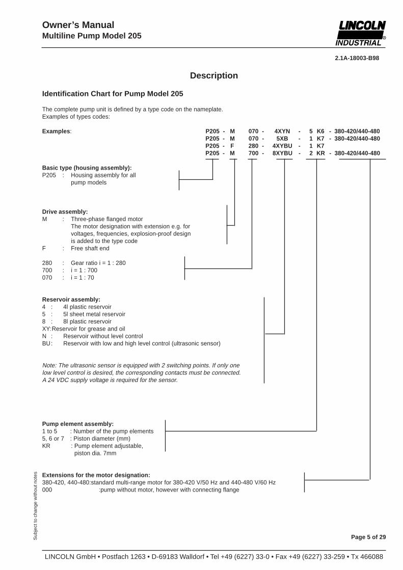
Identification Chart for Pump Model 205
The complete pump unit is defined by a type code on the nameplate.Examples of types codes:
Examples : P205 - M 070 - 4XYN - 5 K6 - 380-420/440-480P205 - M 070 - 5XB - 1 K7 - 380-420/440-480P205 - F 280 - 4XYBU - 1 K7P205 - M 700 - 8XYBU - 2 KR - 380-420/440-480
Basic type (housing assembly):P205 : Housing assembly for all
pump models
Drive assembly:M : Three-phase flanged motor
The motor designation with extension e.g. forvoltages, frequencies, explosion-proof designis added to the type code
F : Free shaft end
280 : Gear ratio i = 1 : 280700 : i = 1 : 700070 : i = 1 : 70
Reservoir assembly:4 : 4l plastic reservoir5 : 5l sheet metal reservoir8 : 8l plastic reservoirXY:Reservoir for grease and oilN : Reservoir without level controlBU: Reservoir with low and high level control (ultrasonic sensor)
Note: The ultrasonic sensor is equipped with 2 switching points. If only onelow level control is desired, the corresponding contacts must be connected.A 24 VDC supply voltage is required for the sensor.
Pump element assembly:1 to 5 : Number of the pump elements5, 6 or 7 : Piston diameter (mm)KR : Pump element adjustable,
piston dia. 7mm
Extensions for the motor designation:380-420, 440-480:standard multi-range motor for 380-420 V/50 Hz and 440-480 V/60 Hz000 :pump without motor, however with connecting flange
LINCOLN GmbH • Postfach 1263 • D-69183 Walldorf • Tel +49 (6227) 33-0 • Fax +49 (6227) 33-259 • Tx 466088
2.1A-18003-B98
Page 6 of 29 Sub
ject
to c
hang
e w
ithou
t not
es
Owner’s ManualMultiline Pump Model 205
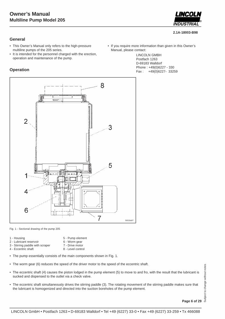
• The pump essentially consists of the main components shown in Fig. 1.
• The worm gear (6) reduces the speed of the driver motor to the speed of the eccentric shaft.
• The eccentric shaft (4) causes the piston lodged in the pump element (5) to move to and fro, with the result that the lubricant issucked and dispensed to the outlet via a check valve.
• The eccentric shaft simultaneously drives the stirring paddle (3). The rotating movement of the stirring paddle makes sure thatthe lubricant is homogenized and directed into the suction boreholes of the pump element.
1 - Housing 5 - Pump element2 - Lubricant reservoir 6 - Worm gear3 - Stirring paddle with scraper 7 - Drive motor4 - Eccentric shaft 8 - Level control
Fig. 1 - Sectional drawing of the pump 205
Operation
• If you require more information than given in this Owner’sManual, please contact:
LINCOLN GMBHPostfach 1263D-69183 WalldorfPhone : +49(0)6227 - 330Fax : +49(0)6227- 33259
• This Owner’s Manual only refers to the high-pressuremultiline pumps of the 205 series.
• It is intended for the personnel charged with the erection,operation and maintenance of the pump.
General
50018a97
2.1A-18003-B98
LINCOLN GmbH • Postfach 1263 • D-69183 Walldorf • Tel +49 (6227) 33-0 • Fax +49 (6227) 33-259 • Tx 466088
Owner’s ManualMultiline Pump Model 205
Page 7 of 29Sub
ject
to c
hang
e w
ithou
t not
es
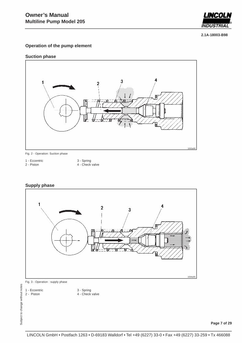
Operation of the pump element
Suction phase
Fig. 2 - Operation: Suction phase
1 - Eccentric 3 - Spring2 - Piston 4 - Check valve
1003a95
Fig. 3 - Operation : supply phase
1004a95
Supply phase
1 - Eccentric 3 - Spring2 - Piston 4 - Check valve
LINCOLN GmbH • Postfach 1263 • D-69183 Walldorf • Tel +49 (6227) 33-0 • Fax +49 (6227) 33-259 • Tx 466088
2.1A-18003-B98
Page 8 of 29 Sub
ject
to c
hang
e w
ithou
t not
es
Owner’s ManualMultiline Pump Model 205
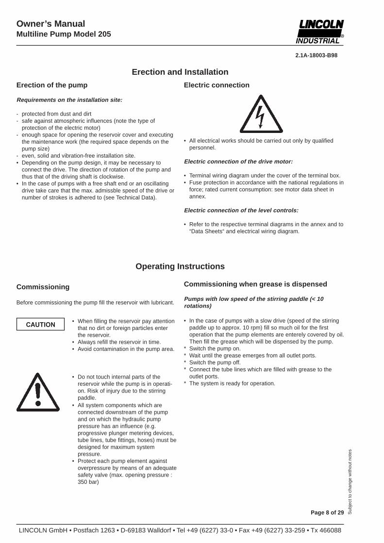
• All electrical works should be carried out only by qualifiedpersonnel.
Electric connection of the drive motor:
• Terminal wiring diagram under the cover of the terminal box.• Fuse protection in accordance with the national regulations in
force; rated current consumption: see motor data sheet inannex.
Electric connection of the level controls:
• Refer to the respective terminal diagrams in the annex and to“Data Sheets“ and electrical wiring diagram.
Electric connection
Erection and Installation
Erection of the pump
Requirements on the installation site:
- protected from dust and dirt- safe against atmospheric influences (note the type of
protection of the electric motor)- enough space for opening the reservoir cover and executing
the maintenance work (the required space depends on thepump size)
- even, solid and vibration-free installation site.• Depending on the pump design, it may be necessary to
connect the drive. The direction of rotation of the pump andthus that of the driving shaft is clockwise.
• In the case of pumps with a free shaft end or an oscillatingdrive take care that the max. admissble speed of the drive ornumber of strokes is adhered to (see Technical Data).
Operating Instructions
Commissioning when grease is dispensed
Pumps with low speed of the stirring paddle (< 10rotations)
• In the case of pumps with a slow drive (speed of the stirringpaddle up to approx. 10 rpm) fill so much oil for the firstoperation that the pump elements are enterely covered by oil.Then fill the grease which will be dispensed by the pump.
* Switch the pump on.* Wait until the grease emerges from all outlet ports.* Switch the pump off.* Connect the tube lines which are filled with grease to the
outlet ports.* The system is ready for operation.
• All system components which areconnected downstream of the pumpand on which the hydraulic pumppressure has an influence (e.g.progressive plunger metering devices,tube lines, tube fittings, hoses) must bedesigned for maximum systempressure.
• Protect each pump element againstoverpressure by means of an adequatesafety valve (max. opening pressure :350 bar)
• Do not touch internal parts of thereservoir while the pump is in operati-on. Risk of injury due to the stirringpaddle.
• When filling the reservoir pay attentionthat no dirt or foreign particles enterthe reservoir.
• Always refill the reservoir in time.• Avoid contamination in the pump area.
Commissioning
Before commissioning the pump fill the reservoir with lubricant.
CAUTION
2.1A-18003-B98
LINCOLN GmbH • Postfach 1263 • D-69183 Walldorf • Tel +49 (6227) 33-0 • Fax +49 (6227) 33-259 • Tx 466088
Owner’s ManualMultiline Pump Model 205
Page 9 of 29Sub
ject
to c
hang
e w
ithou
t not
es
Pumps with speed of the stirring paddle > 10 rpm
* Unscrew any closure plug or pump element (if the pump isequipped with the maximum number of pump elements) fromthe housing.
* Switch the pump on.• Wait until the grease emerges from all the outlet ports (this
may take a longer time).* Retighten the pump element if the pump is equipped with the
maximum number of pump elements.
• Wait until the grease emerges from all the outlet ports.* Switch the pump off.* Screw the closure plug in again.* Connect the tube lines which are filled with grease to the
outlet ports.• The system is ready for operation.• The lubricant output of adjustable pump elements
can be changed any time (see „Adjustments of the pumpelement“). The outlet tube fitting has to be removed before.
Commissioning when fluid lubricants are dispensed
* Switch the pump on.* As soon as the lubricant emerges from the outlet ports switch
the pump off and connect the lubricant feed lines.• The system is ready for operation.
LINCOLN GmbH • Postfach 1263 • D-69183 Walldorf • Tel +49 (6227) 33-0 • Fax +49 (6227) 33-259 • Tx 466088
2.1A-18003-B98
Page 10 of 29 Sub
ject
to c
hang
e w
ithou
t not
es
Owner’s ManualMultiline Pump Model 205
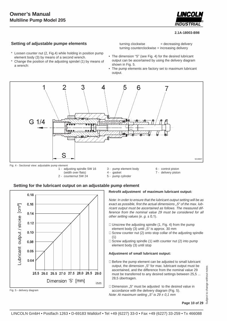
Setting of adjustable pumpe elements
* Loosen counter nut (2, Fig.4) while holding in position pumpelement body (3) by means of a second wrench.
* Change the position of the adjusting spindel (1) by means ofa wrench:
turning clockwise = decreasing deliveryturning counterclockwise = increasing delivery
• The dimension “S” (see Fig. 4) for the desired lubricantoutput can be ascertained by using the delivery diagramshown in Fig. 5.
• The pump elements are factory set to maximum lubricantoutput.
Fig. 4 - Sectional view: adjustable pump element1 - adjusting spindle SW 16 3 - pump element body 6 - control piston
(width over flats) 4 - gasket 7 - delivery piston2 - counternut SW 24 5 - pump cylinder
Setting for the lubricant output on an adjustable pump elementRetrofit adjustment of maximum lubricant output:
Note: In order to ensure that the lubricant output setting will be asexact as possible, first the actual dimensions „S“ of the max. lub-ricant output must be ascertained as follows. The measured dif-ference from the nominal value 29 must be considered for allother setting values (e. g. ± 0,1).
∗ Unscrew the adjusting spindle (1, Fig. 4) from the pumpelement body (3) until „S“ is approx. 30 mm
∗ Screw counter nut (2) onto stop collar of the adjusting spindle(1)
∗ Screw adjusting spindle (1) with counter nut (2) into pumpelement body (3) until stop
Adjustment of small lubricant output:
∗ Before the pump element can be adjusted to small lubricantoutput, the dimension „S“ for max. lubricant output must beascertained, and the difference from the nominal value 29must be transferred to any desired settings between 25,5 ...28,5 übertragen.
∗ Dimension „S“ must be adjusted to the desired value inaccordance with the delivery diagram (Fig. 5).
Note: At maximum setting „S“ is 29 ± 0,1 mm
5019B97
Fig. 5 - delivery diagram
2.1A-18003-B98
LINCOLN GmbH • Postfach 1263 • D-69183 Walldorf • Tel +49 (6227) 33-0 • Fax +49 (6227) 33-259 • Tx 466088
Owner’s ManualMultiline Pump Model 205
Page 11 of 29Sub
ject
to c
hang
e w
ithou
t not
es
Maintenance and Repairs
Before undertaking any repair on thepump observe the following instruc-tions:
Assembly and disassembly of pump elements
Preliminary works:
• Switch the pump off and clean it on the outside.
Important: For cleaning reservoirs made of plastic do notuse polar organic solvents such as alcohol, methyl alcohol,acetone or similar.
• If the pump is filled with grease, the grease can remain in thepump. Fluid lubricants must be drained (unscrew the closureplug or the pump element)
• If the stirring paddle stays ahead of a pump element whichmust be disassembled, turn it until it is on the opposite side.
Attention : The delivery pistons cannot be exchanged! When as-sembling or disassembling several pump elements take care thateach delivery piston remains in the pump cylinder. The deliverypistons are adjusted in the pump cylinder with a tolerance of onlyfew micrometers.
• Switch the drive motor or mechanical drive off and protect itfrom inadvertent restart. Risk of injury by the stirring paddle.
• Slowly loosen the pressure connection fittings on the pumpelements in order to decrease the pressure in the pump andin the system. Risk of injury due to lubricant splashing underhigh pressure.
• Repairs may only be carried out by qualified, skilled person-nel using original LINCOLN INDUSTRIAL replacement parts.
• Provided that the pump dispenses only clean lubricant, itdoes not need any particular maintenance. Since the driveshaft and the pump elements are covered by the lubricantwhich is fed by the pump they are lubricated automatically.
They are however subject to a natural wear which dependson the operating time and operating pressure
and must therefore be replaced.
Assembly of pump elements
• Unscrew the closure plug.• Screw the pump element into the housing by hand and then
tighten it using a fork wrench (SW 27). Tightening torque: 30- 35 Nm
• If fluid lubricants are dispensed, fill them into the reservoir.• Put the pump into operation as described above.
Disassembly of pump elements
• Unscrew the tube line from the outlet port of the pumpelement.
• Apply the fork wrench at the threaded plug of the pumpelement and carefully unscrew the pump element.
• Screw in a closure plug or a new pump element.
Maintenance of the ultrasonic sensor for low or highlevel control (reservoir “XYBU“)
• Take care that the surface of the sensor is clean.
Replacement of gears or drive motors
• Before assembling gears or drive motors apply a specialpaste (e.g. Klüber paste 46MR401) at the boreholes andshaft ends.
LINCOLN GmbH • Postfach 1263 • D-69183 Walldorf • Tel +49 (6227) 33-0 • Fax +49 (6227) 33-259 • Tx 466088
2.1A-18003-B98
Page 12 of 29 Sub
ject
to c
hang
e w
ithou
t not
es
Owner’s ManualMultiline Pump Model 205
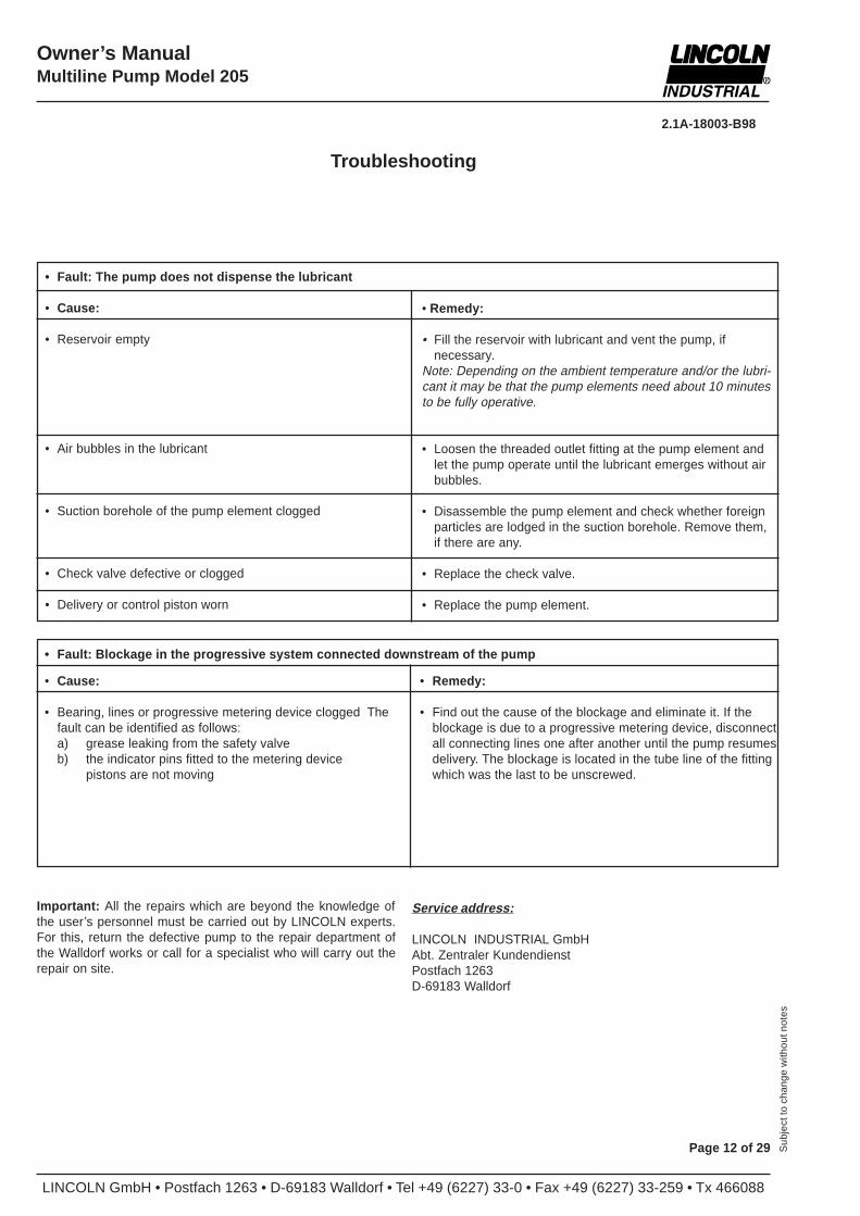
• Fault: The pump does not dispense the lubricant
• Cause:
• Reservoir empty
• Air bubbles in the lubricant
• Suction borehole of the pump element clogged
• Check valve defective or clogged
• Delivery or control piston worn
• Remedy:
• Fill the reservoir with lubricant and vent the pump, ifnecessary.
Note: Depending on the ambient temperature and/or the lubri-cant it may be that the pump elements need about 10 minutesto be fully operative.
• Loosen the threaded outlet fitting at the pump element andlet the pump operate until the lubricant emerges without airbubbles.
• Disassemble the pump element and check whether foreignparticles are lodged in the suction borehole. Remove them,if there are any.
• Replace the check valve.
• Replace the pump element.
Troubleshooting
• Fault: Blockage in the progressive system connected downstream of the pump
• Cause:
• Bearing, lines or progressive metering device clogged Thefault can be identified as follows:a) grease leaking from the safety valveb) the indicator pins fitted to the metering device
pistons are not moving
• Remedy:
• Find out the cause of the blockage and eliminate it. If theblockage is due to a progressive metering device, disconnectall connecting lines one after another until the pump resumesdelivery. The blockage is located in the tube line of the fittingwhich was the last to be unscrewed.
Important: All the repairs which are beyond the knowledge ofthe user’s personnel must be carried out by LINCOLN experts.For this, return the defective pump to the repair department ofthe Walldorf works or call for a specialist who will carry out therepair on site.
Service address:
LINCOLN INDUSTRIAL GmbHAbt. Zentraler KundendienstPostfach 1263D-69183 Walldorf
2.1A-18003-B98
LINCOLN GmbH • Postfach 1263 • D-69183 Walldorf • Tel +49 (6227) 33-0 • Fax +49 (6227) 33-259 • Tx 466088
Owner’s ManualMultiline Pump Model 205
Page 13 of 29Sub
ject
to c
hang
e w
ithou
t not
es
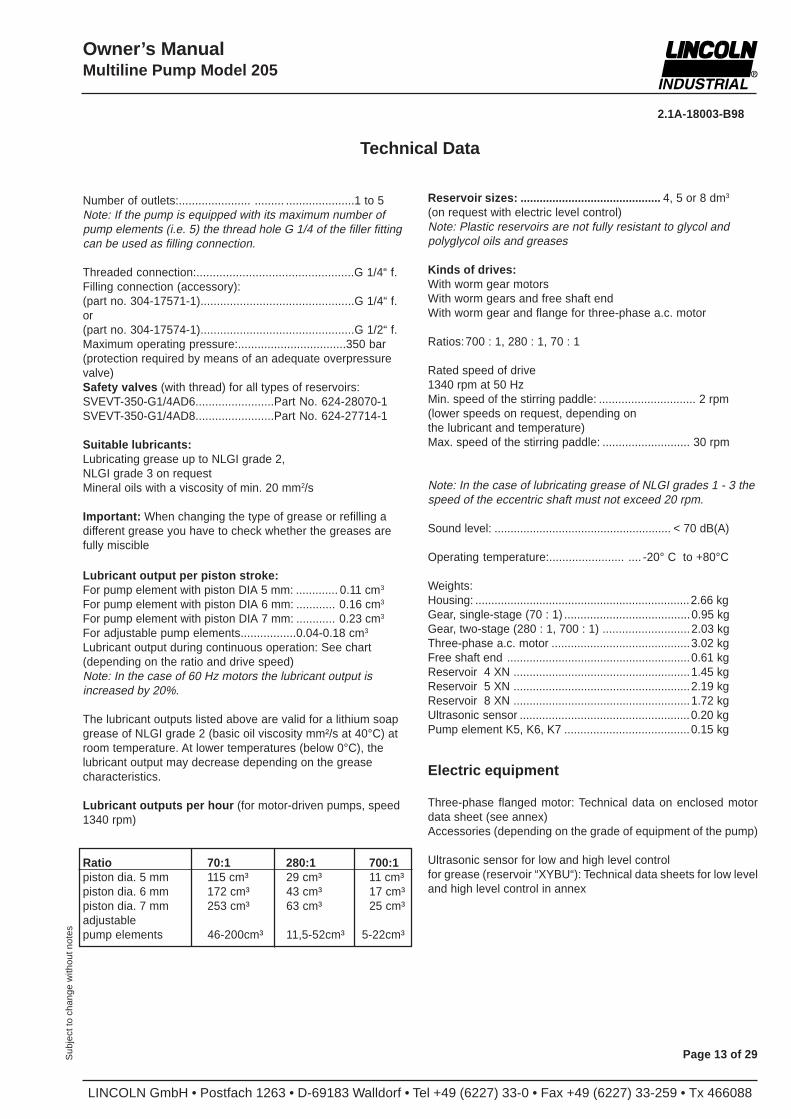
Technical Data
Number of outlets:...................... ......... .....................1 to 5Note: If the pump is equipped with its maximum number ofpump elements (i.e. 5) the thread hole G 1/4 of the filler fittingcan be used as filling connection.
Threaded connection:................................................G 1/4“ f.Filling connection (accessory):(part no. 304-17571-1)...............................................G 1/4“ f.or(part no. 304-17574-1)...............................................G 1/2“ f.Maximum operating pressure:.................................350 bar(protection required by means of an adequate overpressurevalve)Safety valves (with thread) for all types of reservoirs:SVEVT-350-G1/4AD6........................Part No. 624-28070-1SVEVT-350-G1/4AD8........................Part No. 624-27714-1
Suitable lubricants:Lubricating grease up to NLGI grade 2,NLGI grade 3 on requestMineral oils with a viscosity of min. 20 mm2/s
Important: When changing the type of grease or refilling adifferent grease you have to check whether the greases arefully miscible
Lubricant output per piston stroke:For pump element with piston DIA 5 mm: ............. 0.11 cm3
For pump element with piston DIA 6 mm: ............ 0.16 cm3
For pump element with piston DIA 7 mm: ............ 0.23 cm3
For adjustable pump elements.................0.04-0.18 cm3
Lubricant output during continuous operation: See chart(depending on the ratio and drive speed)Note: In the case of 60 Hz motors the lubricant output isincreased by 20%.
The lubricant outputs listed above are valid for a lithium soapgrease of NLGI grade 2 (basic oil viscosity mm²/s at 40°C) atroom temperature. At lower temperatures (below 0°C), thelubricant output may decrease depending on the greasecharacteristics.
Lubricant outputs per hour (for motor-driven pumps, speed1340 rpm)
Ratio 70:1 280:1 700:1piston dia. 5 mm 115 cm³ 29 cm³ 11 cm³piston dia. 6 mm 172 cm³ 43 cm³ 17 cm³piston dia. 7 mm 253 cm³ 63 cm³ 25 cm³adjustablepump elements 46-200cm³ 11,5-52cm³ 5-22cm³
Reservoir sizes: ............................................ 4, 5 or 8 dm3
(on request with electric level control)Note: Plastic reservoirs are not fully resistant to glycol andpolyglycol oils and greases
Kinds of drives:With worm gear motorsWith worm gears and free shaft endWith worm gear and flange for three-phase a.c. motor
Ratios:700 : 1, 280 : 1, 70 : 1
Rated speed of drive1340 rpm at 50 HzMin. speed of the stirring paddle: .............................. 2 rpm(lower speeds on request, depending onthe lubricant and temperature)Max. speed of the stirring paddle: ........................... 30 rpm
Note: In the case of lubricating grease of NLGI grades 1 - 3 thespeed of the eccentric shaft must not exceed 20 rpm.
Sound level: ....................................................... < 70 dB(A)
Operating temperature:....................... .... -20° C to +80°C
Weights:Housing: ...................................................................2.66 kgGear, single-stage (70 : 1) .......................................0.95 kgGear, two-stage (280 : 1, 700 : 1) ...........................2.03 kgThree-phase a.c. motor ...........................................3.02 kgFree shaft end .........................................................0.61 kgReservoir 4 XN .......................................................1.45 kgReservoir 5 XN .......................................................2.19 kgReservoir 8 XN .......................................................1.72 kgUltrasonic sensor .....................................................0.20 kgPump element K5, K6, K7 .......................................0.15 kg
Electric equipment
Three-phase flanged motor: Technical data on enclosed motordata sheet (see annex)Accessories (depending on the grade of equipment of the pump)
Ultrasonic sensor for low and high level controlfor grease (reservoir “XYBU“): Technical data sheets for low leveland high level control in annex
LINCOLN GmbH • Postfach 1263 • D-69183 Walldorf • Tel +49 (6227) 33-0 • Fax +49 (6227) 33-259 • Tx 466088
2.1A-18003-B98
Page 14 of 29 Sub
ject
to c
hang
e w
ithou
t not
es
Owner’s ManualMultiline Pump Model 205
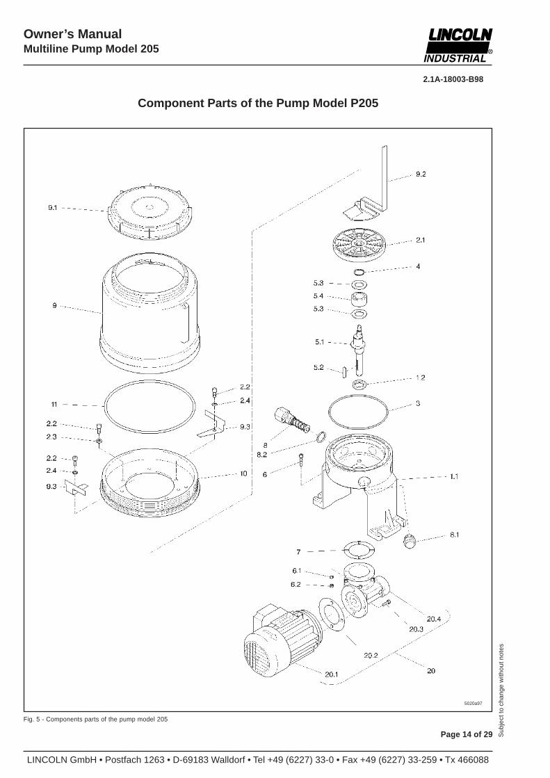
Component Parts of the Pump Model P205
5020a97
Fig. 5 - Components parts of the pump model 205
2.1A-18003-B98
LINCOLN GmbH • Postfach 1263 • D-69183 Walldorf • Tel +49 (6227) 33-0 • Fax +49 (6227) 33-259 • Tx 466088
Owner’s ManualMultiline Pump Model 205
Page 15 of 29Sub
ject
to c
hang
e w
ithou
t not
es
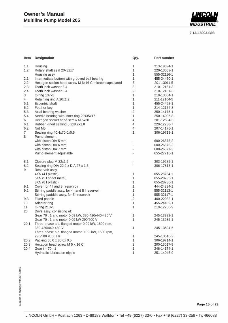
Item Designation Qty. Part number
1.1 Housing 1 313-19694-11.2 Rotary shaft seal 20x32x7 1 220-13059-1
Housing assy. 1 555-32116-12.1 Intermediate bottom with grooved ball bearing 1 455-24460-12.2 Hexagon socket head screw M 6x16 C microencapsulated 5 201-13011-52.3 Tooth lock washer 6.4 3 210-12161-32.4 Tooth lock washer 6.4 2 210-12161-33 O-ring 137x3 1 219-13084-14 Retaining ring A 20x1.2 1 211-12164-55.1 Eccentric shaft 1 455-24458-15.2 Feather key 1 214-12174-35.3 Axial bearing washer 2 250-14175-15.4 Needle bearing with inner ring 20x35x17 1 250-14006-86 Hexagon socket head screw M 5x30 4 201-12594-36.1 Rubber -lined sealing 6.2x9.2x1.0 4 220-12238-76.2 Nut M5 4 207-14176-17 Sealing ring 40.4x70.0x0.5 1 306-19713-18 Pump element
with piston DIA 5 mm - 600-26875-2with piston DIA 6 mm - 600-26876-2with piston DIA 7 mm - 600-26877-2Pump element adjustable - 655-27716-1
8.1 Closure plug M 22x1.5 - 303-19285-18.2 Sealing ring DIA 22.2 x DIA 27 x 1.5 - 306-17813-19 Reservoir assy.
4XN (4 l plastic) 1 655-28734-15XN (5 l sheet metal) 1 655-28735-18XN (8 l plastic) 1 655-28736-1
9.1 Cover for 4 l and 8 l reservoir 1 444-24234-19.2 Stirring paddle assy. for 4 l and 8 l reservoir 1 555-32113-1
Stirring padddle assy. for 5 l reservoir 1 555-32117-19.3 Fixed paddle 2 400-22983-110 Adapter ring 1 455-24459-111 O-ring 210x5 1 219-12730-920 Drive assy. consisting of:
Gear 70 : 1 and motor 0.09 kW, 380-420/440-480 V 1 245-13932-1Gear 70 : 1 and motor 0.09 kW 290/500 V 1 245-13935-1
20.1 Three-phase a.c. flanged motor 0.09 kW, 1500 rpm,380-420/440-480 V 1 245-13504-5Three-phase a.c. flanged motor 0.09. kW, 1500 rpm,290/500 V, 50 Hz 1 245-13510-2
20.2 Packing 50.0 x 80.0x 0.5 1 306-19714-120.3 Hexagon head screw M 5 x 16 C 3 200-13017-920.4 Gear i = 70 : 1 1 246-14174-1
Hydraulic lubrication nipple 1 251-14045-9
LINCOLN GmbH • Postfach 1263 • D-69183 Walldorf • Tel +49 (6227) 33-0 • Fax +49 (6227) 33-259 • Tx 466088
2.1A-18003-B98
Page 16 of 29 Sub
ject
to c
hang
e w
ithou
t not
es
Owner’s ManualMultiline Pump Model 205
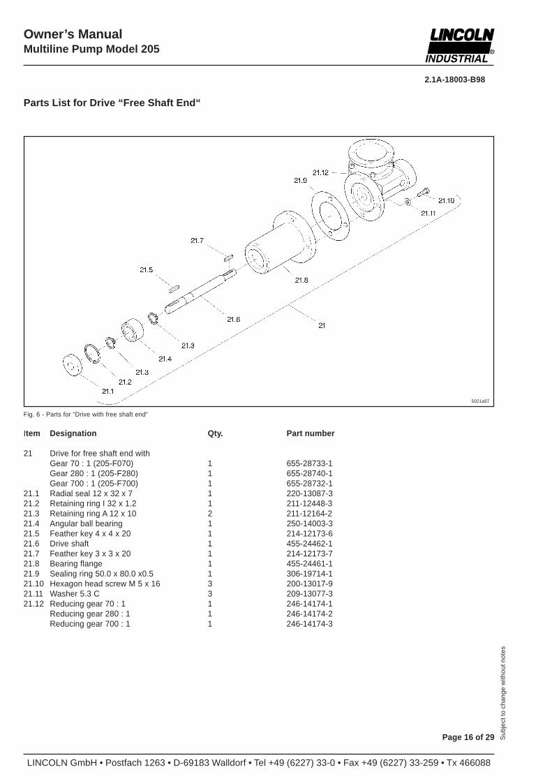
Parts List for Drive “Free Shaft End“
5021a97
Fig. 6 - Parts for “Drive with free shaft end“
Item Designation Qty. Part number
21 Drive for free shaft end withGear 70 : 1 (205-F070) 1 655-28733-1Gear 280 : 1 (205-F280) 1 655-28740-1Gear 700 : 1 (205-F700) 1 655-28732-1
21.1 Radial seal 12 x 32 x 7 1 220-13087-321.2 Retaining ring I 32 x 1.2 1 211-12448-321.3 Retaining ring A 12 x 10 2 211-12164-221.4 Angular ball bearing 1 250-14003-321.5 Feather key 4 x 4 x 20 1 214-12173-621.6 Drive shaft 1 455-24462-121.7 Feather key 3 x 3 x 20 1 214-12173-721.8 Bearing flange 1 455-24461-121.9 Sealing ring 50.0 x 80.0 x0.5 1 306-19714-121.10 Hexagon head screw M 5 x 16 3 200-13017-921.11 Washer 5.3 C 3 209-13077-321.12 Reducing gear 70 : 1 1 246-14174-1
Reducing gear 280 : 1 1 246-14174-2Reducing gear 700 : 1 1 246-14174-3
2.1A-18003-B98
LINCOLN GmbH • Postfach 1263 • D-69183 Walldorf • Tel +49 (6227) 33-0 • Fax +49 (6227) 33-259 • Tx 466088
Owner’s ManualMultiline Pump Model 205
Page 17 of 29Sub
ject
to c
hang
e w
ithou
t not
es
5022a97
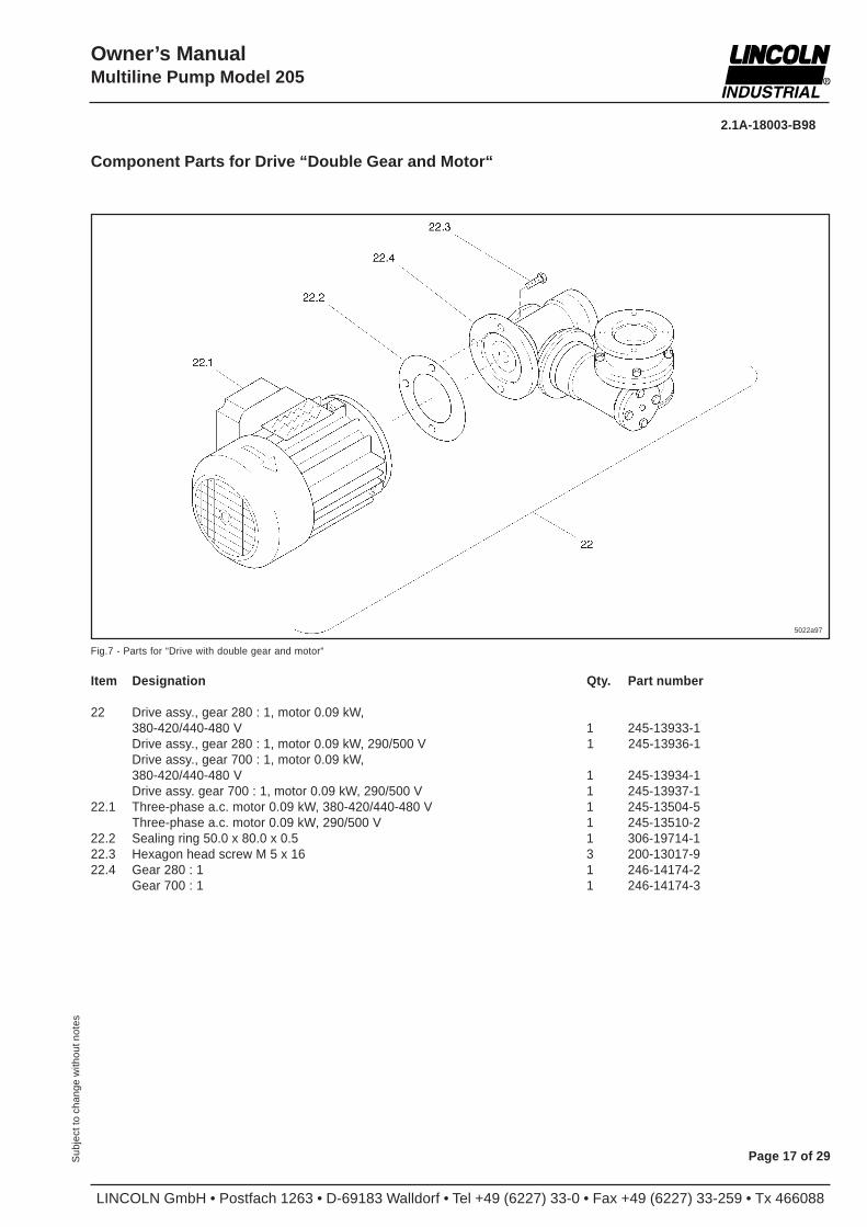
Fig.7 - Parts for “Drive with double gear and motor“
Component Parts for Drive “Double Gear and Motor“
Item Designation Qty. Part number
22 Drive assy., gear 280 : 1, motor 0.09 kW,380-420/440-480 V 1 245-13933-1Drive assy., gear 280 : 1, motor 0.09 kW, 290/500 V 1 245-13936-1Drive assy., gear 700 : 1, motor 0.09 kW,380-420/440-480 V 1 245-13934-1Drive assy. gear 700 : 1, motor 0.09 kW, 290/500 V 1 245-13937-1
22.1 Three-phase a.c. motor 0.09 kW, 380-420/440-480 V 1 245-13504-5Three-phase a.c. motor 0.09 kW, 290/500 V 1 245-13510-2
22.2 Sealing ring 50.0 x 80.0 x 0.5 1 306-19714-122.3 Hexagon head screw M 5 x 16 3 200-13017-922.4 Gear 280 : 1 1 246-14174-2
Gear 700 : 1 1 246-14174-3
LINCOLN GmbH • Postfach 1263 • D-69183 Walldorf • Tel +49 (6227) 33-0 • Fax +49 (6227) 33-259 • Tx 466088
2.1A-18003-B98
Page 18 of 29 Sub
ject
to c
hang
e w
ithou
t not
es
Owner’s ManualMultiline Pump Model 205
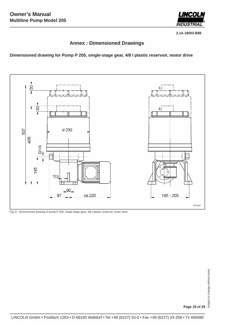
Annex : Dimensioned Drawings
Fig. 8 - Dimensioned drawing of pump P 205, single-stage gear, 4/8 l plastic reservoir, motor drive
5023a97
Dimensioned drawing for Pump P 205, single-stage gear, 4/8 l plastic reservoir, motor drive
2.1A-18003-B98
LINCOLN GmbH • Postfach 1263 • D-69183 Walldorf • Tel +49 (6227) 33-0 • Fax +49 (6227) 33-259 • Tx 466088
Owner’s ManualMultiline Pump Model 205
Page 19 of 29Sub
ject
to c
hang
e w
ithou
t not
es
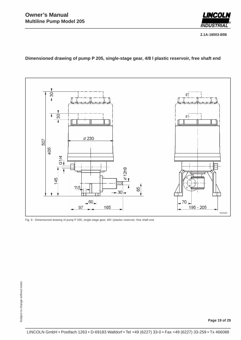
Fig. 9 - Dimensioned drawing of pump P 205, single-stage gear, 4/8 l plastisc reservoir, free shaft end
5024a97
Dimensioned drawing of pump P 205, single-stage gear, 4/8 l plastic reservoir, free shaft end
LINCOLN GmbH • Postfach 1263 • D-69183 Walldorf • Tel +49 (6227) 33-0 • Fax +49 (6227) 33-259 • Tx 466088
2.1A-18003-B98
Page 20 of 29 Sub
ject
to c
hang
e w
ithou
t not
es
Owner’s ManualMultiline Pump Model 205
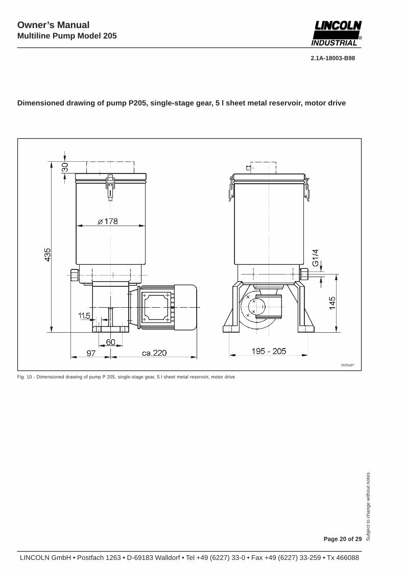
Fig. 10 - Dimensioned drawing of pump P 205, single-stage gear, 5 l sheet metal reservoir, motor drive
5025a97
Dimensioned drawing of pump P205, single-stage gear, 5 l sheet metal reservoir, motor drive
2.1A-18003-B98
LINCOLN GmbH • Postfach 1263 • D-69183 Walldorf • Tel +49 (6227) 33-0 • Fax +49 (6227) 33-259 • Tx 466088
Owner’s ManualMultiline Pump Model 205
Page 21 of 29Sub
ject
to c
hang
e w
ithou
t not
es
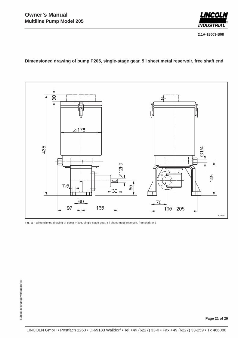
Dimensioned drawing of pump P205, single-stage gear, 5 l sheet metal reservoir, free shaft end
5026a97
Fig. 11 - Dimensioned drawing of pump P 205, single-stage gear, 5 l sheet metal reservoir, free shaft end
LINCOLN GmbH • Postfach 1263 • D-69183 Walldorf • Tel +49 (6227) 33-0 • Fax +49 (6227) 33-259 • Tx 466088
2.1A-18003-B98
Page 22 of 29 Sub
ject
to c
hang
e w
ithou
t not
es
Owner’s ManualMultiline Pump Model 205
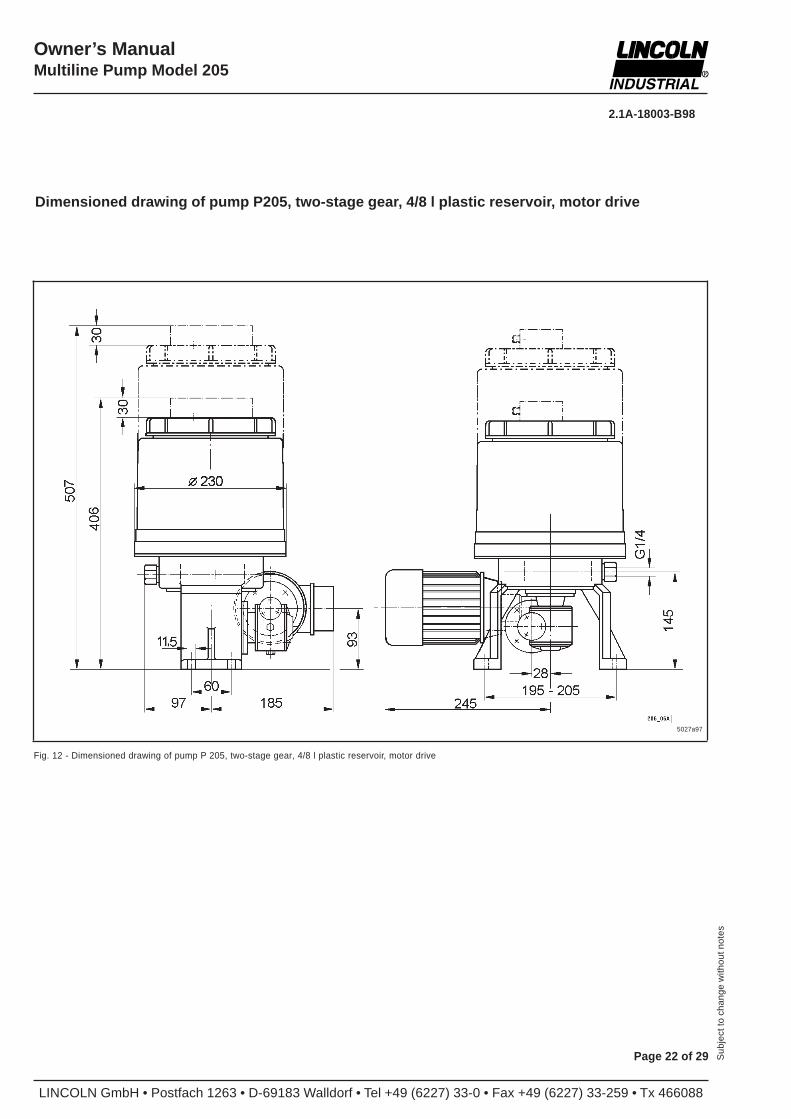
Fig. 12 - Dimensioned drawing of pump P 205, two-stage gear, 4/8 l plastic reservoir, motor drive
Dimensioned drawing of pump P205, two-stage gear, 4/8 l plastic reservoir, motor drive
5027a97
2.1A-18003-B98
LINCOLN GmbH • Postfach 1263 • D-69183 Walldorf • Tel +49 (6227) 33-0 • Fax +49 (6227) 33-259 • Tx 466088
Owner’s ManualMultiline Pump Model 205
Page 23 of 29Sub
ject
to c
hang
e w
ithou
t not
es
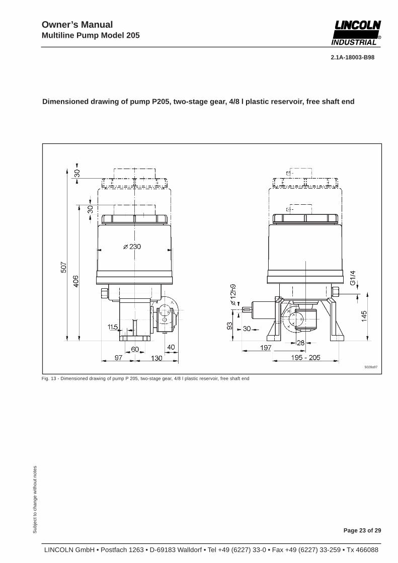
Fig. 13 - Dimensioned drawing of pump P 205, two-stage gear, 4/8 l plastic reservoir, free shaft end
Dimensioned drawing of pump P205, two-stage gear, 4/8 l plastic reservoir, free shaft end
5028a97
LINCOLN GmbH • Postfach 1263 • D-69183 Walldorf • Tel +49 (6227) 33-0 • Fax +49 (6227) 33-259 • Tx 466088
2.1A-18003-B98
Page 24 of 29 Sub
ject
to c
hang
e w
ithou
t not
es
Owner’s ManualMultiline Pump Model 205
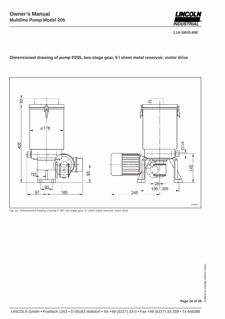
Dimensioned drawing of pump P205, two-stage gear, 5 l sheet metal reservoir, motor drive
Fig. 14 - Dimensioned drawing of pump P 205, two-stage gear, 5 l sheet metal reservoir, motor drive
5029a97
2.1A-18003-B98
LINCOLN GmbH • Postfach 1263 • D-69183 Walldorf • Tel +49 (6227) 33-0 • Fax +49 (6227) 33-259 • Tx 466088
Owner’s ManualMultiline Pump Model 205
Page 25 of 29Sub
ject
to c
hang
e w
ithou
t not
es
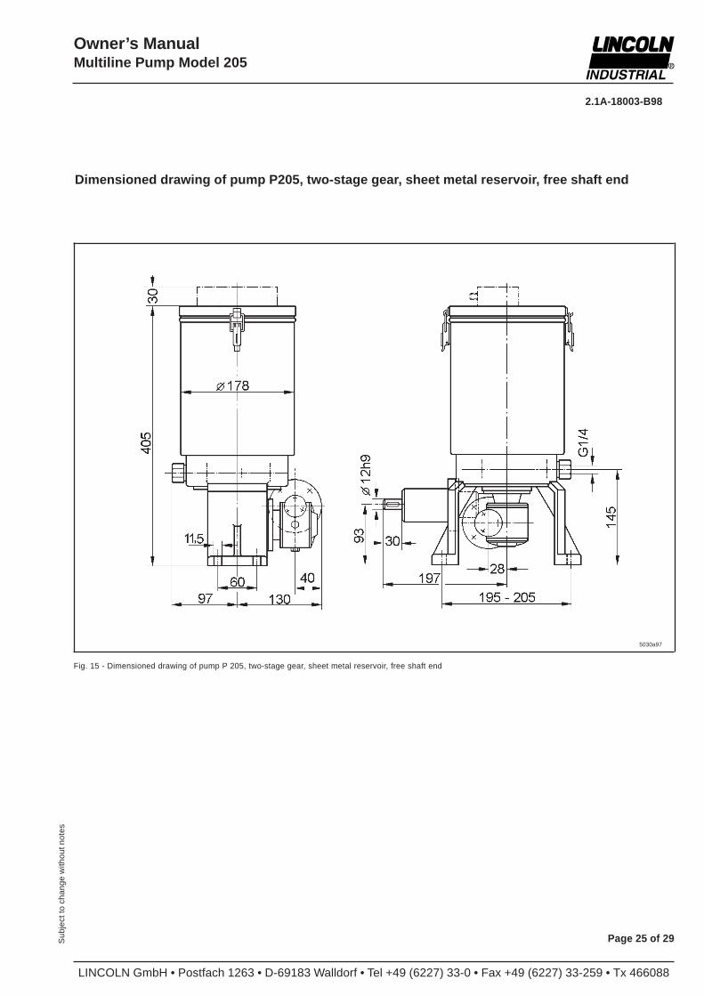
Fig. 15 - Dimensioned drawing of pump P 205, two-stage gear, sheet metal reservoir, free shaft end
Dimensioned drawing of pump P205, two-stage gear, sheet metal reservoir, free shaft end
5030a97
LINCOLN GmbH • Postfach 1263 • D-69183 Walldorf • Tel +49 (6227) 33-0 • Fax +49 (6227) 33-259 • Tx 466088
2.1A-18003-B98
Page 26 of 29 Sub
ject
to c
hang
e w
ithou
t not
es
Owner’s ManualMultiline Pump Model 205
Pump model 205 Units 205 Units
Motor type DIM 56B4 DIM 56B4
Frequency f 50 60 [Hz] 50 [Hz]
Nominal power P 0,09 0,11 [kW] 0,09 [kW]
Nominal speed n 1340 1610 [rpm] 1340 [rpm]
Rated torque M 0,64 0,65 [Nm] 0,64 [Nm]
Nominal current I N 0,78 ___ [A] at 220-240 V 0,62 [A] at 290 V
0,45 ___ [A] at 380-415 V
___ 0,78 [A] at 243-277 V
___ 0,45 [A] at 420-480 V 0,36 [A] at 500 V
Starting current ratio IA/I
N2,6 2,6 [A] 2,9 [A]
Power factor cos j 0,67 0,67 0,62
Efficiency h 57 57 [% ] 52
Frame size 56 56
Type of construction B14/V18 B14/V18
Type of protection IP 55 56
Insulation class F F
Weight approx. 2,9 [kg] approx.2,9 [kg]
Flange Ø80 [mm] Ø80 [mm]
Shaft end Ø9 x 20 [mm] Ø9 x 20 [mm]
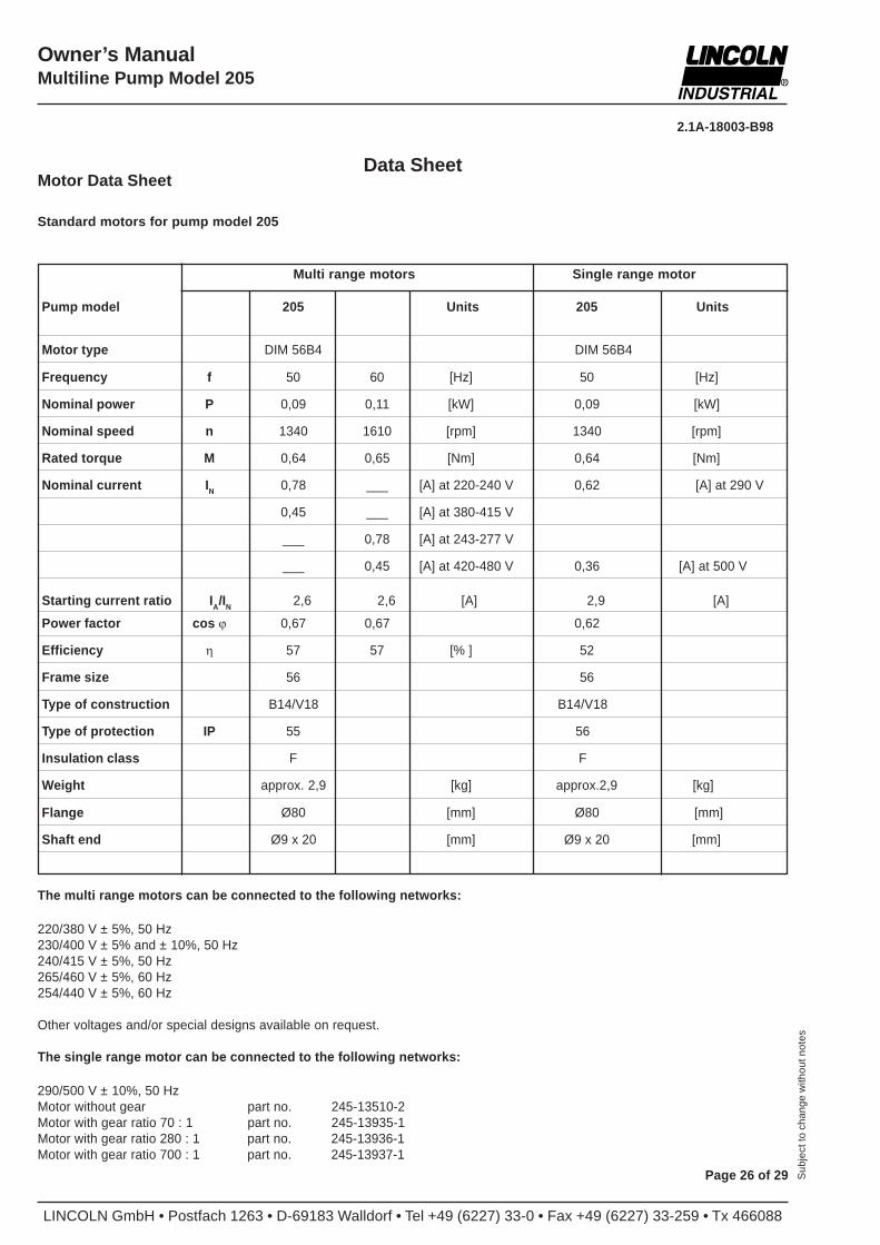
Motor Data Sheet
Standard motors for pump model 205
Data Sheet
The multi range motors can be connected to the following networks:
220/380 V ± 5%, 50 Hz230/400 V ± 5% and ± 10%, 50 Hz240/415 V ± 5%, 50 Hz265/460 V ± 5%, 60 Hz254/440 V ± 5%, 60 Hz
Other voltages and/or special designs available on request.
The single range motor can be connected to the following networks:
290/500 V ± 10%, 50 HzMotor without gear part no. 245-13510-2Motor with gear ratio 70 : 1 part no. 245-13935-1Motor with gear ratio 280 : 1 part no. 245-13936-1Motor with gear ratio 700 : 1 part no. 245-13937-1
Multi range motors Single range motor
2.1A-18003-B98
LINCOLN GmbH • Postfach 1263 • D-69183 Walldorf • Tel +49 (6227) 33-0 • Fax +49 (6227) 33-259 • Tx 466088
Owner’s ManualMultiline Pump Model 205
Page 27 of 29Sub
ject
to c
hang
e w
ithou
t not
es
Data Sheet for Ultrasonic Sensor
Reservoir size: ............................................ Part number:4 l plastic reservoir.................. ..................... ..664-36939-15 l sheet metal reservoir......... .................... ....664-36939-28 l plastic reservoir............... ..................... .....664-36939-3
Description of operation
This remote sensor is a solid state proximity type for 24 VDCwhich uses the echo delay-time method for distance sensing . Itsenses a sound-reflecting object which enters the sound conefrom any direction. The objects to be sensed may be solid orliquid.
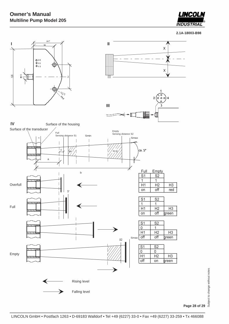
Installation
Figure I (dimensions in mm)Any mounting positionKeep a free space around the sound cone of a distance “x“(x = 60 mm) from reflecting objects (figure I).
Connection
By means of cable socket (figure III) part no. 237-13442-2
Pin1 L+ DC 20 ... 30 V2 S Switching output “High level“ (NO)3 L- Ground (GND)4 S2 Switching input “Low level“ (NC)
The connections are polarized, short-circuit proof and overload-proof. In the case of electrical faults it is recommended to useshielded lines.
Operation
Switching range (figure IV)a Unusable blind zoneb Sensing rangec Overfill rangeHV Hysteresis „High level“HL Hysteresis „Low level“
The objects are sensed reliably in the set switching range withinan opening angle of the sound cone of 5°. If the reflecting condi-tions are good, the objects can also be sensed outside the soundof cone. Keep the blind zone “a“ free from objects. These wouldlead to undefined switching states. Take care that the surface ofthe transducer is clean.
Display:Reservoir empty H2 is litFilling level O.K. H2 is not litReservoir full H1 is litSupply voltage H3 is lit: greenOverfull signal H3 is lit: red
Technical data
Ambient temperature: -25...70°CSensing range: 50...500 mm*Sensing distance „High level“ S1: 60 mm*Sensing distance „Low level“ S2: depends on the
reservoir sizeHysteresis „High level“ HV: 20 mmHysteresis „Low level“ HL: 50 mmSwitching point fault : 0.17% / K* measured on the housing surface
SupplyRated operational voltage: U
E24 V DC
Operating voltage range: UB
20...30VDCAdmissible residual ripple : 10%Open-circuit power consumption: <60 mA
Switching output:Rated normal current: I
E<200 mA
Voltage drop: UD
<3 VSpurious switch-on pulse: suppressedSwitching function „High level“: NO contact
switching on“plus“ „Low level“: NC contact
switching on“plus“
Typical values:Availability delay: 250 msReflection area: 10 x 10 mm2
Ultrasonic frequency: 400 kHzSwitching frequency : 8 HzResolution: 1 mmProtection: IP 65
LINCOLN GmbH • Postfach 1263 • D-69183 Walldorf • Tel +49 (6227) 33-0 • Fax +49 (6227) 33-259 • Tx 466088
2.1A-18003-B98
Page 28 of 29 Sub
ject
to c
hang
e w
ithou
t not
es
Owner’s ManualMultiline Pump Model 205
Full Empty
S1 S2
1 1
H1 H2 H3
on off red
x
x
����
+�
+�
+�
��
��
+<� +<�
����������9ROO
6FKDOWDEVWDQG�6�
���������/HHU
6FKDOWDEVWDQG�6�
Wandleroberfläche
c
b
a
SmaxSmin
FD����
Gehäuseoberfläche
1LYHDX�VWHLJHQG
1LYHDX�IDOOHQG
hEHUYROO
9ROO
/HHU
6�
6�
Smax
S1 S2
1 1
H1 H2 H3
on off green
S1 S2
0 1
H1 H2 H3
off off green
S1 S2
0 0
H1 H2 H3
off on green
I II
III
IVSurface of the transducer
Surface of the housing
FullSensing distance S1
EmptySensing distance S2
Overfull
Full
Empty
Rising level
Falling level
2.1A-18003-B98
LINCOLN GmbH • Postfach 1263 • D-69183 Walldorf • Tel +49 (6227) 33-0 • Fax +49 (6227) 33-259 • Tx 466088
Owner’s ManualMultiline Pump Model 205
Page 29 of 29Sub
ject
to c
hang
e w
ithou
t not
es
Manufacturer’s declaration in accordance withthe EC Machinery Directive 89/392/EECAnnex II B
We herewith declare that the
Multiline Pump Model 205
in the design supplied by us, is intended to be installed in anymachine and that its commissioning is forbidden as long as it hasnot been stated that the machine into which the pump will be builtis in conformity with the decisions of the EC Machinery Directivein the version of 91/368/EEC.
Applied harmonized standards in particular
EN 292 T1/T2
prEN 809
EN 563
Walldorf, Aug. 25, 1997, pp. Z. Paluncic