
MULTIMETERING Nemo 72 Le - ime-messgeraete.de · MULTIMETERING Elektrische Messgrössenerfassung im...
9
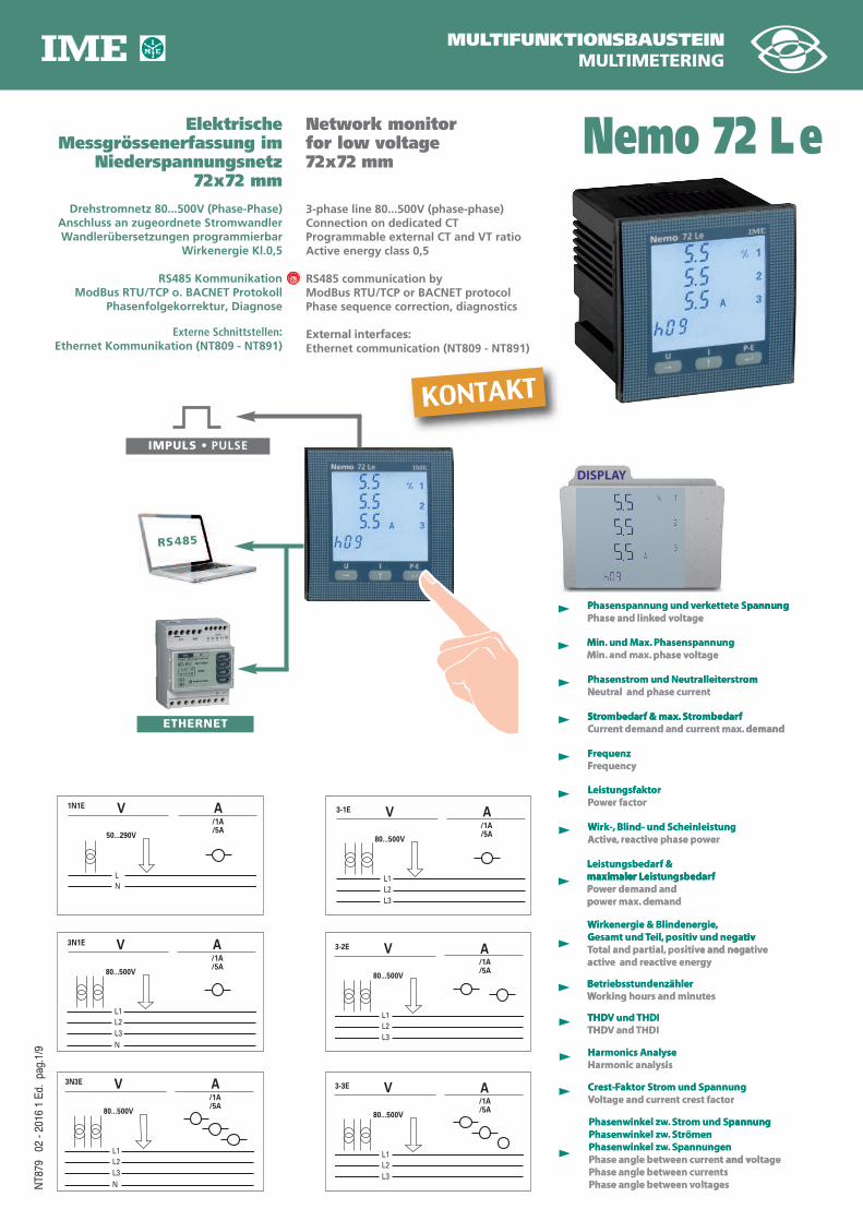
MULTIFUNKTIONSBAUSTEIN MULTIMETERING Elektrische Messgrössenerfassung im Niederspannungsnetz 72x72 mm Drehstromnetz 80...500V (Phase-Phase) Anschluss an zugeordnete Stromwandler Wandlerübersetzungen programmierbar Wirkenergie Kl.0,5 RS485 Kommunikation ModBus RTU/TCP o. BACNET Protokoll Phasenfolgekorrektur, Diagnose Externe Schnittstellen: Ethernet Kommunikation (NT809 - NT891) Network monitor for low voltage 72x72 mm 3-phase line 80...500V (phase-phase) Connection on dedicated CT Programmable external CT and VT ratio Active energy class 0,5 RS485 communication by ModBus RTU/TCP or BACNET protocol Phase sequence correction, diagnostics External interfaces: Ethernet communication (NT809 - NT891) NT879 02 - 2016 1 Ed. pag.1/9 Nemo 72 L e Phasenspannung und verkettete Spannung Phase and linked voltage Phasenstrom und Neutralleiterstrom Neutral and phase current Strombedarf & max. Strombedarf Current demand and current max. demand Frequenz Frequency Leistungsfaktor Power factor Wirk-, Blind- und Scheinleistung Active, reactive phase power Leistungsbedarf & maximaler Leistungsbedarf Power demand and power max. demand Wirkenergie & Blindenergie, Gesamt und Teil, positiv und negativ Total and partial, positive and negative active and reactive energy Betriebsstundenzähler Working hours and minutes THDV und THDI THDV and THDI Harmonics Analyse Harmonic analysis Phasenwinkel zw. Strom und Spannung Phasenwinkel zw. Strömen Phasenwinkel zw. Spannungen Phase angle between current and voltage Phase angle between currents Phase angle between voltages Min. und Max. Phasenspannung Min. and max. phase voltage Crest-Faktor Strom und Spannung Voltage and current crest factor DISPLAY P P N P S M M oltage ed v hase and link P pannung e S et ett k er hasenspannung und v P t en r al and phase cur eutr N om erstr alleit eutr om und N hasenstr P f edar omb tr S f & max. edar omb tr S oltage phase v and max. in. . M hasenspannung P ax. und M in. . M pannung om C S F F P L A W maximaler L L demand t max. en r t demand and cur en r ur C f edar omb tr S f & max. edar omb tr S y equenc r F equenz r F or t er fac w o P or eistungsfakt L er w o e phase p tiv eac r , , e tiv c A Blind- und Scheinleistung k-, , ir W f edar eistungsb maximaler L f & edar eistungsb L demand p P maximaler L ac T G W THD THD W B demand er max. w o p er demand and w o P f edar eistungsb maximaler L y g e ener tiv eac e and r tiv ac e and nega ositiv p tial, , otal and par T To tiv ositiv und nega p eil, , T t und esam G , gie gie & Blindener ener k ir W and THDI V THD und THDI V THD es ing hours and minut k or W iebsstundenzähler etr B e tiv e and nega tiv H H V C sis monic analy ar H se naly monics A ar H oltages een v w et hase angle b P ts en r een cur w et hase angle b P t and v en r een cur w et hase angle b P pannungen S . el zw w. hasenwink P trömen S . el zw w. hasenwink P pannung om und S tr S . el zw w. hasenwink P or t est fac t cr en r oltage and cur V Vo pannung om und S tr or S akt est-F r C oltage t and v pannung 3-3E /1A /5A L1 L2 L3 A V 80...500V 3N3E /1A /5A L1 L2 L3 N A V 80...500V 3N1E /1A /5A L1 L2 L3 N A V 80...500V 3-1E /1A /5A L1 L2 L3 A V 80...500V 1N1E /1A /5A L N A V 50...290V 3-2E /1A /5A L1 L2 L3 A V 80...500V RS485 IMPULS • PULSE ETHERNET KONTAKT
Transcript of MULTIMETERING Nemo 72 Le - ime-messgeraete.de · MULTIMETERING Elektrische Messgrössenerfassung im...
MULTIFUNKTIONSBAUSTEINMULTIMETERING
ElektrischeMessgrössenerfassung im
Niederspannungsnetz72x72 mm
Drehstromnetz 80...500V (Phase-Phase)Anschluss an zugeordnete StromwandlerWandlerübersetzungen programmierbar
Wirkenergie Kl.0,5
RS485 Kommunikation ModBus RTU/TCP o. BACNET Protokoll
Phasenfolgekorrektur, Diagnose
Externe Schnittstellen:Ethernet Kommunikation (NT809 - NT891)
Network monitorfor low voltage72x72 mm
3-phase line 80...500V (phase-phase)Connection on dedicated CTProgrammable external CT and VT ratioActive energy class 0,5
RS485 communication byModBus RTU/TCP or BACNET protocolPhase sequence correction, diagnostics
External interfaces:Ethernet communication (NT809 - NT891)
NT8
79
02 -
2016
1 E
d.pa
g.1/
9
Nemo 72 Le
Phasenspannung und verkettete Spannung Phase and linked voltage
Phasenstrom und Neutralleiterstrom Neutral and phase current
Strombedarf & max. StrombedarfCurrent demand and current max. demand
FrequenzFrequency
LeistungsfaktorPower factor
Wirk-, Blind- und ScheinleistungActive, reactive phase power
Leistungsbedarf & maximaler LeistungsbedarfPower demand and power max. demand
Wirkenergie & Blindenergie, Gesamt und Teil, positiv und negativTotal and partial, positive and negative active and reactive energy
BetriebsstundenzählerWorking hours and minutes
THDV und THDITHDV and THDI
Harmonics AnalyseHarmonic analysis
Phasenwinkel zw. Strom und SpannungPhasenwinkel zw. StrömenPhasenwinkel zw. SpannungenPhase angle between current and voltagePhase angle between currentsPhase angle between voltages
Min. und Max. PhasenspannungMin. and max. phase voltage
Crest-Faktor Strom und SpannungVoltage and current crest factor
DISPLAY
EINGANGINPUT
PP
NP
S
MM
oltageed vhase and linkPpannunge Setettkerhasenspannung und vP
tenral and phase cureutrNom erstralleiteutrom und NhasenstrP
fedarombtr Sf & max.edarombtrS
oltage phase v and max.in.in. and max.Mhasenspannung Pax. und Min.in. und MM
pannung
om
CS
FF
PL
AW
maximaler LL
INPUTEINGANG
demandt max.enrt demand and curenrurCfedarombtr Sf & max.edarombtrS
yequencrFequenzrF
orter facwoPoreistungsfaktL
erwoe phase ptiveac r,, retivcA Blind- und Scheinleistungk-,k-, Blind- und ScheinleistungirW
fedareistungsbmaximaler Lf & edareistungsbL
demand
pPmaximaler L
acTGW
THDTHD
WB
demander max.woper demand and woP
fedareistungsbmaximaler L
yge enertiveace and rtivace and negaositiv ptial,tial, potal and parTTotal and par
tivositiv und nega peil,eil, pTt und esamG,giegie & BlindenerenerkirW
and THDIV THDund THDIV THD
esing hours and minutkorWiebsstundenzähleretrB
e tive and negativ
HH
VC
sismonic analyarHsenalymonics AarH
oltageseen vwethase angle bPtsenreen curwethase angle bPt and venreen curwethase angle bP
pannungen S.el zwel zw.hasenwinkPtrömen S.el zwel zw.hasenwinkP
pannungom und Str S.el zwel zw.hasenwinkP
ortest fact crenroltage and curVVoltage and curpannungom und Stror Saktest-FrC
oltaget and v
pannung
3-3E
/1A/5A
L1L2L3
AV
80...500V
3N3E
/1A/5A
L1L2L3N
AV
80...500V
3N1E
/1A/5A
L1L2L3N
AV
80...500V
3-1E
/1A/5A
L1L2L3
AV
80...500V
1N1E
/1A/5A
LN
AV
50...290V
3-2E
/1A/5A
L1L2L3
AV
80...500V
RS485
IMPULS • PULSE
ETHERNET
KONTAKT
NT8
79
02 -
2016
1 E
d.pa
g.2/
9
1 Spannung, Strom, Leistung, Ah positiv & negativ / 1 Voltage, current, power, Ah positive and negative
♦ Auswahloption On choice ● Bestelloption On choice
KOMMUNIKATION
COMMUNICATION
AUSGANG
OUTPUT
ANZEIGE
DISPLAY
EINGANG
INPUT
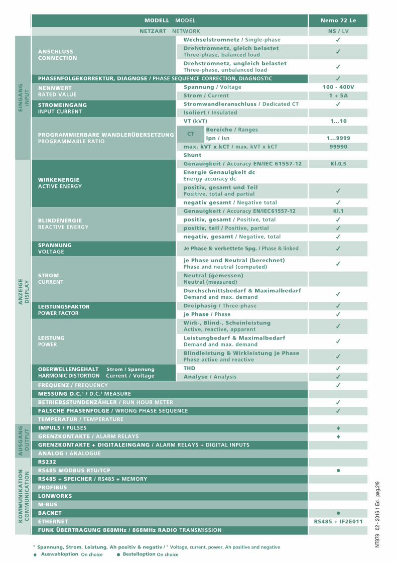
MODELL MODEL Nemo 72 Le
NETZART NETWORK NS / LV
ANSCHLUSSCONNECTION
Wechselstromnetz / Single-phase 4
Drehstromnetz, gleich belastetThree-phase, balanced load 4
Drehstromnetz, ungleich belastetThree-phase, unbalanced load 4
PHASENFOLGEKORREKTUR, DIAGNOSE / PHASE SEQUENCE CORRECTION, DIAGNOSTIC 4
NENNWERTRATED VALUE
Spannung / Voltage 100 - 400V
Strom / Current 1 + 5A
STROMEINGANGINPUT CURRENT
Stromwandleranschluss / Dedicated CT 4
Isoliert / Insulated
PROGRAMMIERBARE WANDLERÜBERSETZUNGPROGRAMMABLE RATIO
VT (kVT) 1...10
CTBereiche / Ranges
Ipn / Isn 1...9999
max. kVT x kCT / max. kVT x kCT 99990
Shunt
WIRKENERGIEACTIVE ENERGY
Genauigkeit / Accuracy EN/IEC 61557-12 Kl.0,5
Energie Genauigkeit dcEnergy accuracy dc
positiv, gesamt und TeilPositive, total and partial 4
negativ gesamt / Negative total 4
BLINDENERGIEREACTIVE ENERGY
Genauigkeit / Accuracy EN/IEC 61557-12 Kl.1
positiv, gesamt / Positive, total 4
positiv, teil / Positive, partial 4
negativ, gesamt / Negative, total 4
SPANNUNGVOLTAGE
Je Phase & verkettete Spg. / Phase & linked 4
STROMCURRENT
je Phase und Neutral (berechnet)Phase and neutral (computed) 4
Neutral (gemessen)Neutral (measured)
Durchschnittsbedarf & MaximalbedarfDemand and max. demand 4
LEISTUNGSFAKTORPOWER FACTOR
Dreiphasig / Three-phase 4
je Phase / Phase 4
LEISTUNGPOWER
Wirk-, Blind-, ScheinleistungActive, reactive, apparent 4
Leistungbedarf & MaximalbedarfDemand and max. demand 4
Blindleistung & Wirkleistung je PhasePhase active and reactive 4
OBERWELLENGEHALT Strom / SpannungHARMONIC DISTORTION Current / Voltage
THD 4
Analyse / Analysis 4
FREQUENZ / FREQUENCY 4
MESSUNG D.C.1 / D.C.1 MEASURE
BETRIEBSSTUNDENZÄHLER / RUN HOUR METER 4
FALSCHE PHASENFOLGE / WRONG PHASE SEQUENCE 4
TEMPERATUR / TEMPERATURE
IMPULS / PULSES ♦GRENZKONTAKTE / ALARM RELAYS ♦GRENZKONTAKTE + DIGITALEINGANG / ALARM RELAYS + DIGITAL INPUTS
ANALOG / ANALOGUE
RS232
RS485 MODBUS RTU/TCP ●RS485 + SPEICHER / RS485 + MEMORY
PROFIBUS
LONWORKS
M-BUS
BACNET ●ETHERNET RS485 + IF2E011
FUNK ÜBERTRAGUNG 868MHz / 868MHz RADIO TRANSMISSION
ANZEIGE
Display : LCD mit Hintergrundbeleuchtung
= Backlighting einstellbar: 0 - 35 - 70 - 100%
Beleuchtung schaltet sich nach ca. 20 Sekunden ohne Betätigung der Fronttastatur
automatisch ab (auf definierbaren Wert)
100% Hintergrundbeleuchtung nach erstmaliger Betätigung der Tastatur
Anzeige: 10.000 4-stellig
Messgrösseneinheit: automatisch, abhängig von eingestellten Wandlerubersetzungen
Auflösung: automatisch
Dezimalstellen: automatisch
Display-Aktualisierung: 1 Update/s
Energiezähler: 8-stellig
Die Anzeigewerte sind auf insgesamt 3 Menu-Seiten unterteilt und können
durch Betätigen der entsprechenden Funktionstaste aufgerufen werden.
Display-Seitenwechsel in Abhängigkeit des eingestellten Messmodus
PROGRAMMIERBARE PARAMETER
Programmierung: über Touchpad-Fronttastatur, 3 Tasten
Programmierzugang: Passwort-geschützt
Programmiermenü: auf zwei Ebenen unterteilt
LEVEL 1
Kundenspezifische Display-Seite
Netzanschlussart
Integrationszeit durchschnittliche Leistung / Strom
Display-Hintergrundbeleuchtung
Anlauf Betriebsstundenerfassung
RS485-Kommunikation
Funktion Relais-Ausgang: Impuls / Alarm / Remote-Switching
LEVEL 2
Externe Spannungs-und Stromwandlerverhältnisse
EINGANG
Netzarten: Wechselstromnetz, Drehstromnetz 3- und 4-LeiteranschlussAnschluss uber externe zugeordnete Stromwandler
DISPLAY
Type of display: backlighted liquid crystal
Selectable backlighting: 0 – 35 – 70 – 100%
Backlighting automatic reduction (to the selected value) after approximately 20
seconds of keyboard idle
100% backlighting after first pressure on the keyboard
Reading points: 10.000 4 digits
Engineering unit: automatic display according to the loaded VT and CT ratios
Resolution: automatic
Decimal point: automatic
Display updating: 1 reading/s
Energy count: 8 digits
Display is subdivided into 3 menus which are accessible through the relevant
function keys:
Display pages change according to the programmed measuring mode
PROGRAMMABLE PARAMETERS
Programming: through front keyboard, 3 keys
Programming access: password-protected
Programming menu: subdivided on two levels
LEVEL 1
Customized display page
Connection
Average power/current delay time
Display backlighting
Lapsed time count start
RS485 communication
Relay output function (pulses, alarm, state switching)
LEVEL 2
External voltage or current transformer ratio
INPUT
Network: Single-phase, three-phase network 3 and 4-wire
Connection with external dedicated current transformers
NT8
79
02 -
2016
1 E
d.pa
g.3/
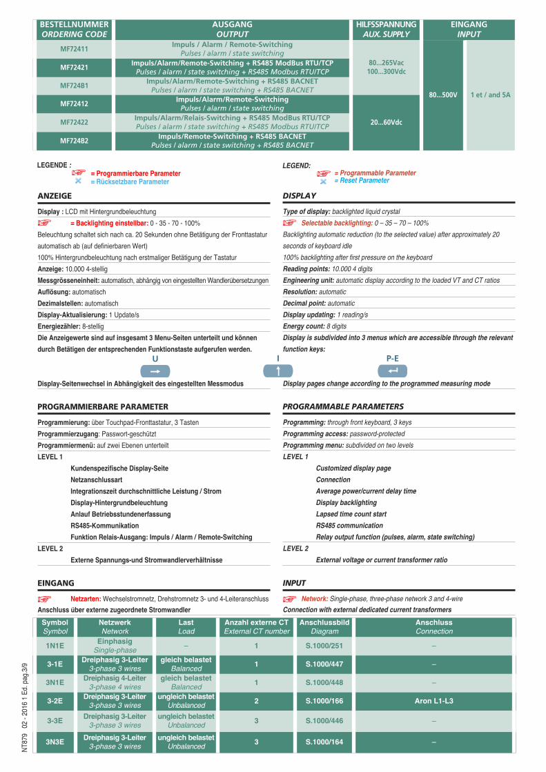
9BESTELLNUMMER ORDERING CODE
AUSGANGOUTPUT
HILFSSPANNUNGAUX. SUPPLY
EINGANGINPUT
MF72411Impuls / Alarm / Remote-SwitchingPulses / alarm / state switching
80...265Vac 100...300Vdc
80...500V 1 et / and 5A
MF72421Impuls/Alarm/Remote-Switching + RS485 ModBus RTU/TCPPulses / alarm / state switching + RS485 Modbus RTU/TCP
MF724B1Impuls/Alarm/Remote-Switching + RS485 BACNETPulses / alarm / state switching + RS485 BACNET
MF72412Impuls/Alarm/Remote-SwitchingPulses / alarm / state switching
20...60VdcMF72422Impuls/Alarm/Relais-Switching + RS485 ModBus RTU/TCPPulses / alarm / state switching + RS485 Modbus RTU/TCP
MF724B2Impuls/Remote-Switching + RS485 BACNET
Pulses / alarm / state switching + RS485 BACNET
U I P-EU I P-EU I P-E
LEGENDE := Programmierbare Parameter= Rücksetzbare Parameter
LEGEND:= Programmable Parameter= Reset Parameter
SymbolSymbol
NetzwerkNetwork
LastLoad
Anzahl externe CTExternal CT number
AnschlussbildDiagram
AnschlussConnection
1N1E EinphasigSingle-phase
– 1 S.1000/251 –
3-1E Dreiphasig 3-Leiter3-phase 3 wires
gleich belastetBalanced
1 S.1000/447 –
3N1E Dreiphasig 4-Leiter3-phase 4 wires
gleich belastetBalanced
1 S.1000/448 –
3-2E Dreiphasig 3-Leiter3-phase 3 wires
ungleich belastetUnbalanced
2 S.1000/166 Aron L1-L3
3-3E Dreiphasig 3-Leiter3-phase 3 wires
ungleich belastetUnbalanced
3 S.1000/446 –
3N3E Dreiphasig 3-Leiter3-phase 3 wires
ungleich belastetUnbalanced
3 S.1000/164 –
Three-phase voltage rating Un: 400-100V (phase-phase)
Three-phase voltage: 80...500V (phase-phase)
Single-phase voltage: 50 - 290V
External VT ratio: 1...10,0 (max. VT primary voltage 1200V)
In rated current: 5A – 1A
Istantaneous overload: 20 In/0,5s
External CT ratio: 1...9999 (max. primary current 50kA/5A – 10kA/1A)
Fn Rated frequency: 50Hz – 400Hz (automatic selection)
Admitted variation: 45...65Hz (fn 50Hz) – 360...440Hz (fn 400Hz)
Type of measurement: true root mean square
Harmonic contents: up to the 50th harmonics (50Hz)
Current peak factor: 2
Starting time (energy count): < 5s
Voltage rated burden: ≤ 0,2VA (phase-neutral to the rated voltage)
Current rated burden: ≤ 1VA (for phase to the max. current 6A)
Current/average power delay time: 5/8/10/15/20/30/60 min.
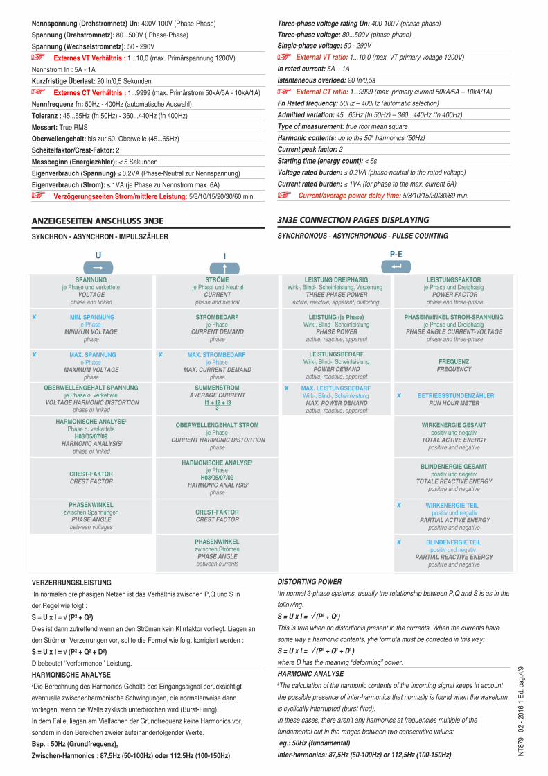
3N3E CONNECTION PAGES DISPLAYING
SYNCHRONOUS - ASYNCHRONOUS - PULSE COUNTING
DISTORTING POWER1In normal 3-phase systems, usually the relationship between P,Q and S is as in the
following:
S = U x I = √ (P2 + Q2)
This is true when no distortionis present in the currents. When the currents have
some way a harmonic contents, yhe formula must be corrected in this way:
S = U x I = √ (P2 + Q2 + D2 )
where D has the meaning “deforming” power.
HARMONIC ANALYSE2The calculation of the harmonic contents of the incoming signal keeps in account
the possible presence of inter-harmonics that normally is found when the waveform
is cyclically interrupted (burst fired).
In these cases, there aren’t any harmonics at frequencies multiple of the
fundamental but in the ranges between two consecutive values:
eg.: 50Hz (fundamental)
inter-harmonics: 87,5Hz (50-100Hz) or 112,5Hz (100-150Hz)
Nennspannung (Drehstromnetz) Un: 400V 100V (Phase-Phase)
Spannung (Drehstromnetz): 80...500V ( Phase-Phase)
Spannung (Wechselstromnetz): 50 - 290V
Externes VT Verhältnis : 1...10,0 (max. Primärspannung 1200V)
Nennstrom In : 5A - 1A
Kurzfristige Überlast: 20 In/0,5 Sekunden
Externes CT Verhältnis : 1...9999 (max. Primärstrom 50kA/5A - 10kA/1A)
Nennfrequenz fn: 50Hz - 400Hz (automatische Auswahl)
Toleranz : 45...65Hz (fn 50Hz) - 360...440Hz (fn 400Hz)
Messart: True RMS
Oberwellengehalt: bis zur 50. Oberwelle (45...65Hz)
Scheitelfaktor/Crest-Faktor: 2
Messbeginn (Energiezähler): < 5 Sekunden
Eigenverbrauch (Spannung) ≤ 0,2VA (Phase-Neutral zur Nennspannung)
Eigenverbrauch (Strom): ≤ 1VA (je Phase zu Nennstrom max. 6A)
Verzögerungszeiten Strom/mittlere Leistung: 5/8/10/15/20/30/60 min.
ANZEIGESEITEN ANSCHLUSS 3N3E
SYNCHRON - ASYNCHRON - IMPULSZÄHLER
VERZERRUNGSLEISTUNG1In normalen dreiphasigen Netzen ist das Verhältnis zwischen P,Q und S in
der Regel wie folgt :
S = U x I = √ (P² + Q²)
Dies ist dann zutreffend wenn an den Strömen kein Klirrfaktor vorliegt. Liegen an
den Strömen Verzerrungen vor, sollte die Formel wie folgt korrigiert werden :
S = U x I = √ (P² + Q² + D²)
D bebeutet ‘’verformende’’ Leistung.
HARMONISCHE ANALYSE2Die Berechnung des Harmonics-Gehalts des Eingangssignal berucksichtigt
eventuelle zwischenharmonische Schwingungen, die normalerweise dann
vorliegen, wenn die Welle zyklisch unterbrochen wird (Burst-Firing).
In dem Falle, liegen am Vielfachen der Grundfrequenz keine Harmonics vor,
sondern in den Bereichen zweier aufeinanderfolgender Werte.
Bsp. : 50Hz (Grundfrequenz),
Zwischen-Harmonics : 87,5Hz (50-100Hz) oder 112,5Hz (100-150Hz)
SPANNUNGje Phase und verkettete
VOLTAGEphase and linked
STRÖME je Phase und Neutral
CURRENTphase and neutral
LEISTUNG DREIPHASIGWirk-, Blind-, Scheinleistung, Verzerrung 1
THREE-PHASE POWER active, reactive, apparent, distorting1
LEISTUNGSFAKTORje Phase und Dreiphasig
POWER FACTORphase and three-phase
� MIN. SPANNUNGje Phase
MINIMUM VOLTAGEphase
STROMBEDARFje Phase
CURRENT DEMANDphase
LEISTUNG (je Phase)Wirk-, Blind-, Scheinleistung
PHASE POWER active, reactive, apparent
PHASENWINKEL STROM-SPANNUNGje Phase und Dreiphasig
PHASE ANGLE CURRENT-VOLTAGEphase and three-phase
� MAX. SPANNUNGje Phase
MAXIMUM VOLTAGEphase
� MAX. STROMBEDARFje Phase
MAX. CURRENT DEMANDphase
LEISTUNGSBEDARFWirk-, Blind-, Scheinleistung
POWER DEMANDactive, reactive, apparent
FREQUENZFREQUENCY
OBERWELLENGEHALT SPANNUNGje Phase o. verkettete
VOLTAGE HARMONIC DISTORTIONphase or linked
SUMMENSTROMAVERAGE CURRENT
I1 + I2 + I33
� MAX. LEISTUNGSBEDARFWirk-, Blind-, ScheinleistungMAX. POWER DEMANDactive, reactive, apparent
� BETRIEBSSTUNDENZÄHLERRUN HOUR METER
HARMONISCHE ANALYSE2
Phase o. verketteteH03/05/07/09
HARMONIC ANALYSIS2
phase or linked
OBERWELLENGEHALT STROMje Phase
CURRENT HARMONIC DISTORTIONphase
WIRKENERGIE GESAMTpositiv und negativ
TOTAL ACTIVE ENERGYpositive and negative
CREST-FAKTORCREST FACTOR
HARMONISCHE ANALYSE2
je PhaseH03/05/07/09
HARMONIC ANALYSIS2
phase
BLINDENERGIE GESAMTpositiv und negativ
TOTALE REACTIVE ENERGYpositive and negative
PHASENWINKEL zwischen Spannungen
PHASE ANGLE between voltages
CREST-FAKTORCREST FACTOR
� WIRKENERGIE TEILpositiv und negativ
PARTIAL ACTIVE ENERGYpositive and negative
PHASENWINKELzwischen StrömenPHASE ANGLE between currents
� BLINDENERGIE TEILpositiv und negativ
PARTIAL REACTIVE ENERGYpositive and negative
NT8
79
02 -
2016
1 E
d.pa
g.4/
9
U I P-EU I P-E U I P-E
Um die Messwerte, wie in diesem Beispiel, bereinigt darzustellen, werden die
Harmonics-Werte der nächstgelegenen vollen Oberwelle im Bereich zwischen
50...100Hz zugerechnet, hier : 100Hz (2te Oberwelle).
Messzyklen : 5 Updates/sek
LEISTUNGSMITTELWERT
Messgrösse: Wirkleistung
Berechnung: uber eingestellte Zeitperiode
Zeitperiode : 5/8/10/15/20/30/60 min.
PHASENFOLGEKORREKTUR, DIAGNOSE
IME hat die Geräte-Firmware um eine produktspezifische Funktion erweitert, welche
zahlreiche Probleme im Zusammenhang mit Strom- und Spannungsanschlussen
erkennt und korrigiert. Nach Passwort-Eingabe kann diese Funktion angezeigt und
abgeändert werden, unter Voraussetzung dass folgende Kriterein erfulIt sind :
1) Neutralleiter (4-Draht Netz) ist an der entsprechenden Klemme angeschlossen
(normalerweise Kl.11)
2) Die am Wandler angeschlossenen Kabel wurden nicht vertauscht !
Vermeiden Sie es bspw. eine der CT-Messleitungen fur Phase 1
(Geräteklemmen 1 & 3) an den Wandlern CT2 oder CT3 anzuschliessen.
3) Der Leistungsfaktor liegt zwischen 1 und 0,5 induktiv bei jeder Phase
Siehe www.imeitaly.com “TECHNICAL SUPPORT”.
RELAIS AUSGANG
Ausgangsfunktion: Energieimpulse, Umschaltung Relaiszustand
(remote-gesteuert), bistabiler Modus, zeitgesteuerter Modus
IMPULSAUSGANG ENERGIE
Impulsausgang kompatibel mit S0 EN/IEC 62053-31
Optorelais mit potentialfreiem SPST-NO Schliesserkontakt
Kontaktlast : 27Vdc/ac - 50mA
Zuweisbare Messgrösse: Wirk- oder Blindenergie
Impulswertigkeit : 1 pulse/10Wh(varh) – 100Wh(varh) - 1 kWh(varh) –
10 kWh(kvarh) – 100kWh(kvarh) – 1MWh(kvarh) – 10MWh(kvarh)
Impulsdauer: 50 – 100 – 200 - 300 - 400 - 500ms
ALARM
1 Alarm programmierbar
Wenn ein Alarm auftritt, wird die Anomalie durch eine blinkede Anzeige signalisiert.
Durch mehrmaliges Drucken der Taste et kann die mit dem Alarm gekoppelte
Messgrösse, sowie der Alarmtyp angezeigt werden (min. or max.)
Optorelais mit Wechselkontakt SPST-NO potentialfrei
Kontaktlast : 27Vdc/ac - 50mA
Zuweisbare Messgrössen:
Spannung je Phase L1-N / L2-N / L3-N
verkettete Spannung L1-L2 / L2-L3 / L3-L1
Strom je Phase I1 / I2 / I3
Frequenz
Wirkleistung dreiphasig
Blindleistung dreiphasig
Grenzwert Interventionspunkt
Alarmtyp: min. o. max.
To show the results in a standard way, the harmonic contents, as in the example,
are correctly attributed to the nearest central harmonic in the range 50...150Hz that
is 100Hz (second harmonic).
Measuring updateing: 5 reading/sec
POWER DEMAND
Quantity: active power
Calculation: average on the selected time interval
Delay time: 5/8/10/15/20/30/60 min.
PHASE SEQUENCE CORRECTION, DIAGNOSTIC
In the software of the device IME have added a specific functionality to detect and
correct many problems concerning voltage and / or current connection.
This function can be activated through password and allows to display and modify
the connection sequence provided that the following conditions are respected:
1) The neutral wire (in a 4-wire network) is connected to the right terminal
(normally number 11).
2) No crossings between cables connected to CTs (e.g. avoid that on phase 1 of the
meter -terminals 1 and 3 - are connected some way both to CT1 and CT2).
3) The power factor is between 1 and 0,5 - Inductive load - for each phase.
See www.imeitaly.com “TECHNICAL SUPPORT”.
RELAY OUTPUT
Output function: energy pulses, alarm contact, state of relay switching (remote-
controlled), bistable mode, timed mode
ENERGY PULSE OUTPUT
Pulse output compatible with S0 EN/IEC 62053-31
Optorelay with potential-free SPST-NO contact
Contact range: 27Vdc/ac – 50mA
Associated energy: active or reactive
Weight of pulse: 1 pulse/10Wh(varh) - 100Wh(varh) – 1kWh(kvarh) -
10kWh(kvarh) - 100kWh(kvarh) – 1MWh(Mvarh) - 10MWh(Mvarh)
Pulse duration: 50 – 100 – 200 – 300 – 400 – 500ms
ALARM
1 Programmable alarm
In case an alarm occurred, the display is blinking to signal the anomaly.
By pressing many times et key it is possible to display the quantity coupled with the
alarm as well as the alarm type (min. or max.)
Optorelay with potential-free SPST-NO contact
Contact range: 27Vdc/ac – 50mA
Quantities that can be associated:
phase voltage L1-N / L2-N / L3-N
interlinked voltage L1-L2 / L2-L3 / L3-L1
phase currentI1 / I2 / I3
frequency
3-phase active power
3-phase reactive power
Intervention threshold
Type alarm: min. or max.NT8
79
02 -
2016
1 E
d.pa
g.5/
9
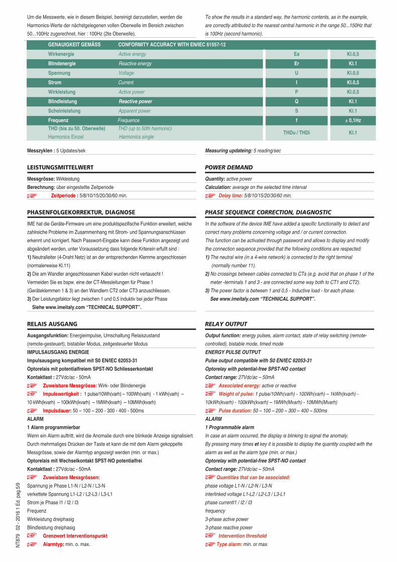
GENAUIGKEIT GEMÄSS CONFORMITY ACCURACY WITH EN/IEC 61557-12
Wirkenergie Active energy Ea Kl.0,5
Blindenergie Reactive energy Er Kl.1
Spannung Voltage U Kl.0,5
Strom Current I Kl.0,5
Wirkleistung Active power P Kl.0,5
Blindleistung Reactive power Q Kl.1
Scheinleistung Apparent power S Kl.1
Frequenz Frequence f ± 0,1Hz
THD (bis zu 50. Oberwelle) THD (up to 50th harmonic)
Harmonics Einzel Harmonics singleTHDu / THDi Kl.1
NT8
79
02 -
2016
1 E
d.pa
g.6/
9
Relay output contact: normally open or normarmally closed
Hysteresis: 0...20%Intervention delay: 0...99s
Reset delay: 0...99s
state of relay switching (remote-controlled), bistable mode
Relay output contact: normally open (no) or normally closed (nC)
t on: delay between activation remote control and change of state of relay
t oF: delay between reset remote control and change of state of relay
Selectable values t on / t oF: 0…99s
State of relay switching (remote-controlled), timed mode
Relay output contact: normally open (no) or normally closed (nC)
t on: delay between activation remote control and change of state of relay
t oF: delay between change of state of relay (activation) and reset
Selectable values t on / t oF: 0…99s
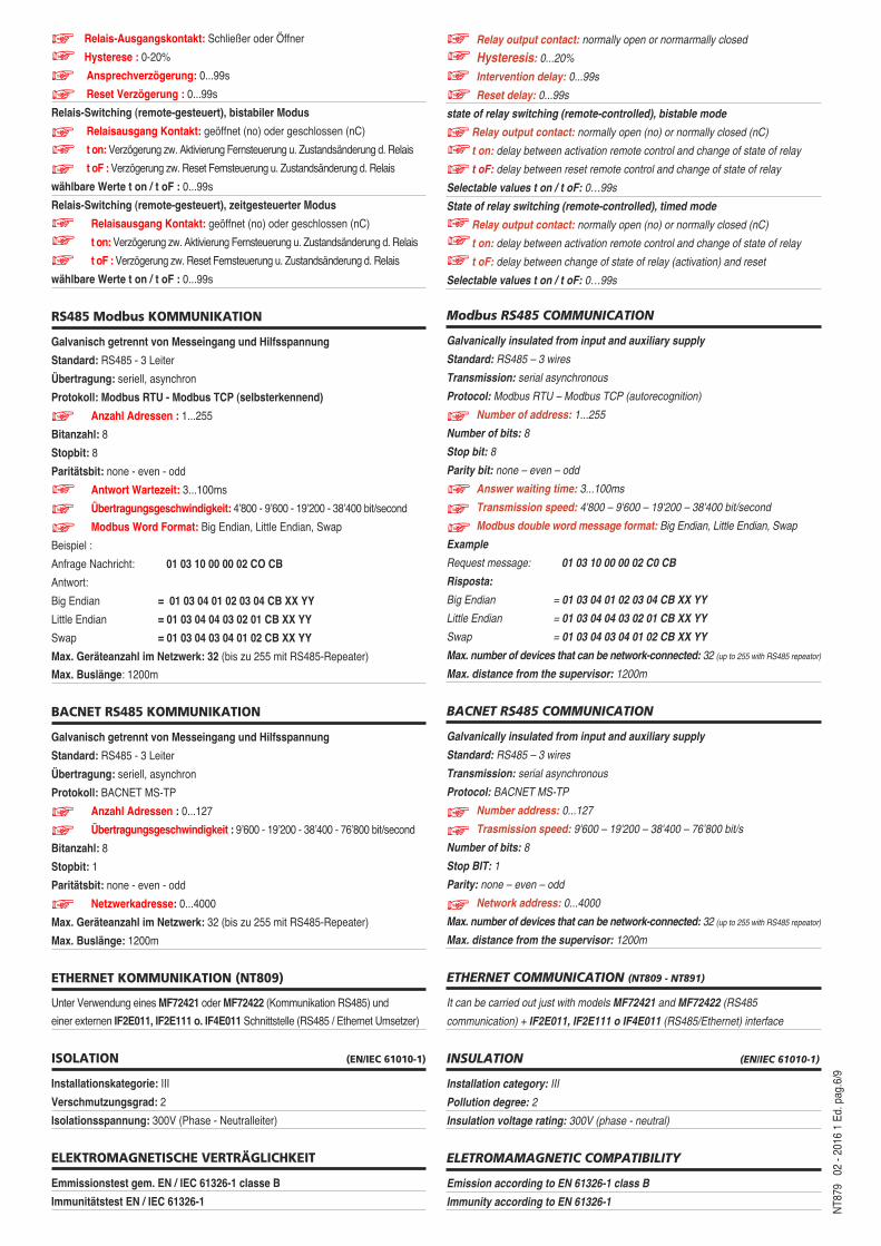
Modbus RS485 COMMUNICATION
Galvanically insulated from input and auxiliary supply
Standard: RS485 – 3 wires
Transmission: serial asynchronous
Protocol: Modbus RTU – Modbus TCP (autorecognition)
Number of address: 1...255
Number of bits: 8
Stop bit: 8
Parity bit: none – even – odd
Answer waiting time: 3...100ms
Transmission speed: 4'800 – 9'600 – 19'200 – 38'400 bit/second
Modbus double word message format: Big Endian, Little Endian, Swap
Example
Request message: 01 03 10 00 00 02 C0 CB
Risposta:
Big Endian = 01 03 04 01 02 03 04 CB XX YY
Little Endian = 01 03 04 04 03 02 01 CB XX YY
Swap = 01 03 04 03 04 01 02 CB XX YY
Max. number of devices that can be network-connected: 32 (up to 255 with RS485 repeator)
Max. distance from the supervisor: 1200m
BACNET RS485 COMMUNICATION
Galvanically insulated from input and auxiliary supply
Standard: RS485 – 3 wires
Transmission: serial asynchronous
Protocol: BACNET MS-TP
Number address: 0...127
Trasmission speed: 9'600 – 19'200 – 38'400 – 76’800 bit/s
Number of bits: 8
Stop BIT: 1
Parity: none – even – odd
Network address: 0...4000
Max. number of devices that can be network-connected: 32 (up to 255 with RS485 repeator)
Max. distance from the supervisor: 1200m
ETHERNET COMMUNICATION (NT809 - NT891)
It can be carried out just with models MF72421 and MF72422 (RS485
communication) + IF2E011, IF2E111 o IF4E011 (RS485/Ethernet) interface
INSULATION (EN/IEC 61010-1)
Installation category: III
Pollution degree: 2
Insulation voltage rating: 300V (phase - neutral)
ELETROMAMAGNETIC COMPATIBILITY
Emission according to EN 61326-1 class B
Immunity according to EN 61326-1
Relais-Ausgangskontakt: Schließer oder Öffner
Hysterese : 0-20%
Ansprechverzögerung: 0...99s
Reset Verzögerung : 0...99s
Relais-Switching (remote-gesteuert), bistabiler Modus
Relaisausgang Kontakt: geöffnet (no) oder geschlossen (nC)
t on: Verzögerung zw. Aktivierung Fernsteuerung u. Zustandsänderung d. Relais
t oF : Verzögerung zw. Reset Fernsteuerung u. Zustandsänderung d. Relais
wählbare Werte t on / t oF : 0...99s
Relais-Switching (remote-gesteuert), zeitgesteuerter Modus
Relaisausgang Kontakt: geöffnet (no) oder geschlossen (nC)
t on: Verzögerung zw. Aktivierung Fernsteuerung u. Zustandsänderung d. Relais
t oF : Verzögerung zw. Reset Fernsteuerung u. Zustandsänderung d. Relais
wählbare Werte t on / t oF : 0...99s
RS485 Modbus KOMMUNIKATION
Galvanisch getrennt von Messeingang und Hilfsspannung
Standard: RS485 - 3 Leiter
Übertragung: seriell, asynchron
Protokoll: Modbus RTU - Modbus TCP (selbsterkennend)
Anzahl Adressen : 1...255
Bitanzahl: 8
Stopbit: 8
Paritätsbit: none - even - odd
Antwort Wartezeit: 3...100ms
Übertragungsgeschwindigkeit: 4’800 - 9’600 - 19’200 - 38’400 bit/second
Modbus Word Format: Big Endian, Little Endian, Swap
Beispiel :
Anfrage Nachricht: 01 03 10 00 00 02 CO CB
Antwort:
Big Endian = 01 03 04 01 02 03 04 CB XX YY
Little Endian = 01 03 04 04 03 02 01 CB XX YY
Swap = 01 03 04 03 04 01 02 CB XX YY
Max. Geräteanzahl im Netzwerk: 32 (bis zu 255 mit RS485-Repeater)
Max. Buslänge: 1200m
BACNET RS485 KOMMUNIKATION
Galvanisch getrennt von Messeingang und Hilfsspannung
Standard: RS485 - 3 Leiter
Übertragung: seriell, asynchron
Protokoll: BACNET MS-TP
Anzahl Adressen : 0...127
Übertragungsgeschwindigkeit : 9’600 - 19’200 - 38’400 - 76’800 bit/second
Bitanzahl: 8
Stopbit: 1
Paritätsbit: none - even - odd
Netzwerkadresse: 0...4000
Max. Geräteanzahl im Netzwerk: 32 (bis zu 255 mit RS485-Repeater)
Max. Buslänge: 1200m
ETHERNET KOMMUNIKATION (NT809)
Unter Verwendung eines MF72421 oder MF72422 (Kommunikation RS485) und
einer externen IF2E011, IF2E111 o. IF4E011 Schnittstelle (RS485 / Ethernet Umsetzer)
ISOLATION (EN/IEC 61010-1)
Installationskategorie: III
Verschmutzungsgrad: 2
Isolationsspannung: 300V (Phase - Neutralleiter)
ELEKTROMAGNETISCHE VERTRÄGLICHKEIT
Emmissionstest gem. EN / IEC 61326-1 classe B
Immunitätstest EN / IEC 61326-1
NT8
79
02 -
2016
1 E
d.pa
g.7/
9HILFSSPANNUNG
Hilfsspannung Uaux ac: 80...265Vac - 48Vac
Nennfrequenz fn: 50 oder 400Hz (automatische Auswahl)
Arbeitsfrequenz : 45…65Hz (fn 50Hz) oder 360...440Hz (fn 400Hz)
Eigenverbrauch : ≤ 2,5VA (230Vac backlight 30%)
Hilfsspannung Uaux dc: 100...300Vdc - 11...60Vdc
Eigenverbrauch : ≤ 2,5W (24Vdc backlight 30%)
Verpolungsschutz
ARBEITSBEDINGUNGEN
Referenztemperatur: 23°C ± 2°C
Arbeitsbereich: - 5...55°C
Grenztemperatur fur Lagerung und Transport: - 25...70°C
Tropenausfuhrung
Max. Verlustleistung1: ≤ 5W1 zur thermischen Dimensionierung des Schaltschrankes
GEHÄUSE
Gehäuse: Schalttafeleibau (Schalttafelsschnitt 68x68mm)
Frontrahmen: 72x72mm
Einbautiefe: 81mm
Gehäusematerial: Polycarbonat, selbstverlöschend
Schutzart : (EN60529): IP54 Front, IP20 Anschlüsse
Gewicht : 250 Gramm
SCHRAUBKLEMMEN
mit Aderendhulse: min.0,05mm2 / max. 4mm2
Draht (flexibel): min.0,05mm2 / max. 2,5mm2
Empfohlenes Drehmoment: 0,5Nm / max.0,8Nm
AUXILIARY SUPPLY
Rated value Uaux ac: 80...265Vac - 48Vac
Rated frequency fn: 50 or 400Hz (automatic selection)
Working frequency: 45…65Hz (fn 50Hz) or 360...440Hz (fn 400Hz)
Rated burden: ≤ 2,5VA (230Vac backlight 30%)
Rated value Uaux dc: 100...300Vdc - 20...60Vdc
Rated burden: ≤ 2,5W (24Vdc backlight 30%)
Protected against incorrect polarity
ENVIRONMENTAL CONDITIONS
Reference temperature: 23°C ± 2°C
Specified operating range: -5...55°C
Limit range for storage and transport: - 25...70°C
Suitable for tropical climates
Max. power dissipation 1: ≤ 5W1For switchboard thermal calculation
HOUSING
Housing: flush mounting (panel cutout 68x68mm)
Front frame: 72x72mm
Depth: 81mm
Housing material: self-extinguishing policarbonate
Protection degree (EN60529): IP54 front frame, IP20 terminals
Weight: 250 grams
TERMINAL CAPACITY
With lag: min.0,05mm2 / max. 4mm2
Flexible cable: min.0,05mm2 / max. 2,5mm2
Tightening torque advised: 0,5Nm / max.0,8Nm
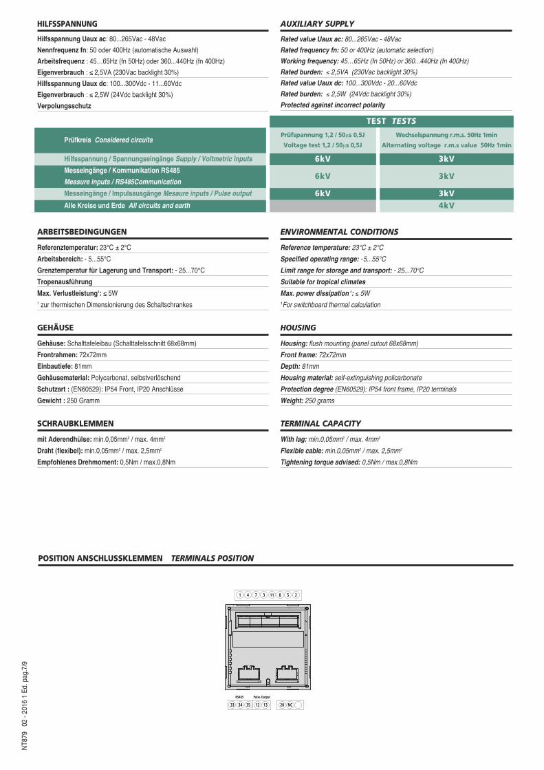
POSITION ANSCHLUSSKLEMMEN TERMINALS POSITION
1
Pulse OutputRS485
4 7 3 11 8 5 2
33 34 35 12 13 20 NC
TEST TESTS
Prüfkreis Considered circuitsPrüfspannung 1,2 / 50μs 0,5J
Voltage test 1,2 / 50μs 0,5J
Wechselspannung r.m.s. 50Hz 1min
Alternating voltage r.m.s value 50Hz 1min
Hilfsspannung / Spannungseingänge Supply / Voltmetric inputs 6kV 3kVMesseingänge / Kommunikation RS485
Measure inputs / RS485Communication6kV 3kV
Messeingänge / Impulsausgänge Mesaure inputs / Pulse output 6kV 3kVAlle Kreise und Erde All circuits and earth 4kV
NT8
79
02 -
2016
1 E
d.pa
g.8/
9
LOAD
S1
P1X
2 5 8 11 1 4 7 3 12 13
OUTPUTI N P U T RS 485
Rx / Tx GND
33 34 35+ –
20
AUX.SUPPLY
21
VOLTAGE CURRENT
L
N
a
A
b
B
2 11
F
S1
P1
2 5 8 11 1 4 7 3 12 13
OUTPUTI N P U T RS 485
Rx / Tx GND
33 34 35+ –
20
AUX.SUPPLY
21
VOLTAGE CURRENT
F
X
XX
a
AL1
L2
L3
NX X X
LOAD
2 5 8 11
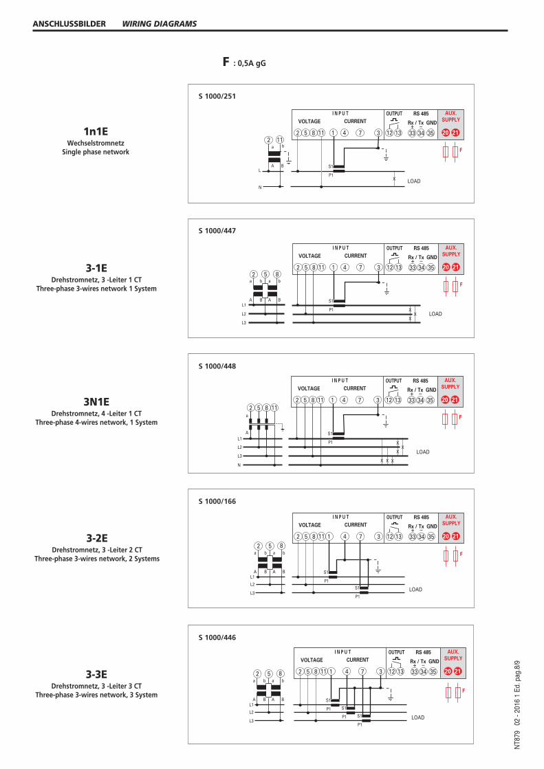
ANSCHLUSSBILDER WIRING DIAGRAMS
S1
P1
2 5 8 11 1 4 7 3 12 13
OUTPUTI N P U T RS 485
Rx / Tx GND
33 34 35+ –
20
AUX.SUPPLY
21
VOLTAGE CURRENT
F
X
XX
a
A
b
B
a
A
b
BL1
L2
L3
LOAD
2 5 8
S1
P1
S1
P1LOAD
2 5 8 11 1 4 7 3 12 13
OUTPUTI N P U T RS 485
Rx / Tx GND
33 34 35+ –
20
AUX.SUPPLY
21
VOLTAGE CURRENT
a
A
b
B
a
A
b
BL1
L2
L3
2 5 8F
S 1000/166
S 1000/448
S 1000/447
S 1000/251
3-1EDrehstromnetz, 3 -Leiter 1 CT
Three-phase 3-wires network 1 System
3N1EDrehstromnetz, 4 -Leiter 1 CT
Three-phase 4-wires network, 1 System
3-2EDrehstromnetz, 3 -Leiter 2 CT
Three-phase 3-wires network, 2 Systems
S1
P1 S1
P1 S1
P1LOAD
2 5 8 11 1 4 7 3 12 13
OUTPUTI N P U T RS 485
Rx / Tx GND
33 34 35+ –
20
AUX.SUPPLY
21
VOLTAGE CURRENT
F
a
A
b
B
a
A
b
BL1
L2
L3
2 5 8
S 1000/446
3-3EDrehstromnetz, 3 -Leiter 3 CT
Three-phase 3-wires network, 3 System
1n1EWechselstromnetz
Single phase network
F : 0,5A gG
S1
P1 S1
P1 S1
P1LOAD
2 5 8 11 1 4 7 3 12 13
OUTPUTI N P U T RS 485
Rx / Tx GND
33 34 35+ –
20
AUX.SUPPLY
21
VOLTAGE CURRENT
a
AL1
L2
L3
N
2 115 8
F
IME Messgeräte behält sich das Recht vor, die technischen Merkmale ohne Benachrichtigung zu ändern
ABMESSUNGEN DIMENSIONS
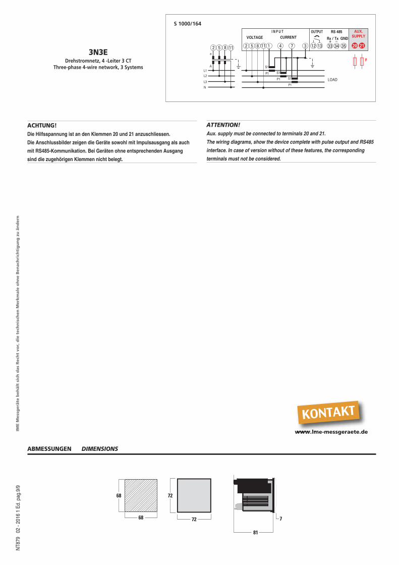
3N3EDrehstromnetz, 4 -Leiter 3 CT
Three-phase 4-wire network, 3 Systems
68
68
72
72
81
7
S 1000/164N
T879
02
- 20
16 1
Ed.
pag.
9/9
ACHTUNG!Die Hilfsspannung ist an den Klemmen 20 und 21 anzuschliessen.
Die Anschlussbilder zeigen die Geräte sowohl mit Impulsausgang als auch
mit RS485-Kommunikation. Bei Geräten ohne entsprechenden Ausgang
sind die zugehörigen Klemmen nicht belegt.
ATTENTION!Aux. supply must be connected to terminals 20 and 21.
The wiring diagrams, show the device complete with pulse output and RS485
interface. In case of version without of these features, the corresponding
terminals must not be considered.
www.ime-messgeraete.de
KONTAKT


![70-200 MHz Digital Oszilloskop HMO Serie 72x.. · 5 Änderungen vorbehalten echnische DatenT 0.3Technische Daten 200 MHz 2 [4] Kanal Digital-Oszilloskop HMO2022 [HMO2024] Alle Angaben](https://static.fdokument.com/doc/165x107/5d50348388c993f62d8b6a28/70-200-mhz-digital-oszilloskop-hmo-serie-72x-5-aenderungen-vorbehalten-echnische.jpg)