Nanostructured Transition Metal Chalcogenides as Materials in
17
F3.1 Eichhöfer, Fenske 1 Subproject F3.1 Nanostructured Transition Metal Chalcogenides as Materials in Lithium Ion Batteries Principle Investigators: Dieter Fenske and Andreas Eichhöfer CFN-Financed Scientists: H. Sommer (1 BAT IIa, 11 months), Jürgen Feuersänger (1/2 BAT IIa, 4 months), V. Andrushko (1 BAT IIa, 9 months), Institut für Anorganische Chemie KIT, Campus Süd, Universität Karlsruhe (TH) Institut für Nanotechnologie KIT, Campus Nord Forschungszentrum Karlsruhe in der Helmholtz-Gemeinschaft
Transcript of Nanostructured Transition Metal Chalcogenides as Materials in
F3.1 Eichhöfer, Fenske
1
Subproject F3.1
Nanostructured Transition Metal Chalcogenides as Materials in Lithium Ion Batteries Principle Investigators: Dieter Fenske and Andreas Eichhöfer CFN-Financed Scientists: H. Sommer (1 BAT IIa, 11 months), Jürgen Feuersänger (1/2 BAT IIa, 4 months), V. Andrushko (1 BAT IIa, 9 months), Institut für Anorganische Chemie KIT, Campus Süd, Universität Karlsruhe (TH) Institut für Nanotechnologie KIT, Campus Nord Forschungszentrum Karlsruhe in der Helmholtz-Gemeinschaft
F3.1 Eichhöfer, Fenske
2
Nanostructured Transition Metal Chalcogenides as Materials in Lithium Ion Batteries Introduction and Summary Materials in use as negative electrodes are actually beside carbon metallic lithium, ternary lithium nitrides as well as lithium alloys.[1] Cathode materials include the intercalation compounds LiCoO2, LiMn2O4 (mostly with dopants as quaternary metal oxides) and recently also polyanionic phosphates and vanadates like LiFePO4, V2O5 and LiV3O8. Future improvements with these systems are driven by changes in the battery chemistry and cell engineering. On the other hand most hope for improvement of the lithium battery technology lies with the design and elaboration of new electrode materials which might lead to higher cell potentials, capacities and/or energy densities. Promising with this respect are for example compounds with multi-electron redox couples like Cr6+/Cr3+. Another important issue is the influence of the morphology of the electrode materials e.g. its nano- or microstructure or porosity. Although related highly porous V2O5 aerogels show initially increased capacities by 100 % problems arise from an enhanced reactivity related to the high surface area and the poor tap density. Transition metal sulfides like CuS were initially successfully used as lithium primary cell materials.[2] In the 70s some researcher realized that layered phases like TiS2 and MoS2 were also candidates as positive electrode materials for rechargeable lithium batteries.[3,4] Whittingham was the first to demonstrate fast, reversible Li insertion into TiS2 over the solid-solution range 0 ≤ x ≤ 1 of LixTiS2.
[5,6] However attempts to make a TiS2/Li0 battery failed because dendrite formation on the Li0 anode caused explosive failure. High temperature cells based on iron sulfide electrodes were considered as a possible energy storage option for the electric vehicle already in the 1980’s.[7] On the other hand the technical feasibility of the electrochemical reaction of alkali metals with sulfur is well-known; high temperature sodium-sulfur batteries[8] are currently in use for certain stationary storage applications, mainly in Japan. In turn a battery based on lithium/elemental sulfur redox couples has a theoretical specific capacity of 1675 mAh g–1 of active material and a theoretical specific energy of 2500 Wh kg–1 assuming complete reaction to form Li2S.[9] Unfortunately the formation of a variety of lithium polysulfide intermediates which are partially soluble in the electrolyte result in severe inefficiencies.[10,11] Nonetheless, in view of the reactivity of sulfur with lithium, it is not surprising that several transition metal sulfides have been reported to react with lithium following a conversion reaction to produce Li2S and metal nanoparticles. These sulfides therefore share characteristics and issues as electrodes with elemental sulfur. For copper sulfides CuS is one of several metals attractive as positive electrodes in lithium primary batteries.[2,12] Its overall conversion reaction to Cu and Li2S proceeds through an intermediate step that entails the formation of Cu2–xS and Li2S and has been shown to be rather reversible.[13,14,15] The performance of this sulfide in a rechargeable battery with liquid electrolytes has been evaluated by a handful of authors;[13,16,17,18] despite the reversibility of the reaction in the first cycle, severe capacity losses are observed very early on in the life of the battery due to irreversible sulfur dissolution in the electrolyte upon cycling.[17] On the contrary, sustained capacities of 350 mAh g–1 are obtained after 60 cycles at 90 °C if the electrolyte is a composite of a PEO-based polymer blended with SiO2 filler. Mixtures of CuS and S have also been used with glass ceramic electrolytes, yielding capacities of almost 700 mAh g–1.[19] These observations are in line with the trend defined by the reported performances of iron [20,21] and nickel sulfides,[22] providing rather clear hint that liquid electrolytes may not be a suitable choice for adequate cycling. The electrochemical conversion of Cu2–x (x = 0 and 0.24) to Li2S and copper has also been shown to be somewhat

F3.1 Eichhöfer, Fenske
3
reversible.[14] As in the case of other sulfides reviewed so far, Cu2S behaves poorly, the initial capacity dropping to negligible values in less than 20 cycles.[23] Goal:
Synthesis of nanostructured binary and ternary transition metal chalcogenides by thermal decomposition of ligand stabilized cluster molecules for use as Battery Electrode Materials
Synthesis of metastable nanostructured Cu2S by thermal decomposition of ligand stabilized cluster molecules and their electrochemical behaviour
In recent years we already succeeded in synthesizing a large number of copper sulfide and selenide cluster molecules.[24] Investigations on thermal properties of copper selenide cluster molecules reveal that for all cluster molecules the phosphine ligand shells are cleaved at temperatures between 60 °C and 200 °C depending on the experimental conditions (Helium gas flow or vacuum), the type of phosphine ligand and the size of the cluster molecules.[25]
Scheme 1
The residues of the thermal treatment were found to be nanostructured Cu2Se with crystallite sizes of approximately 15 nm which means that the 1 to 2.5 nm sized cluster cores of the precursor cluster molecules simultaneously grow during this process (fig. 1). A mixture of processes and factors including the strength of the Cu–P bond, the boiling point of the phosphine ligand as well as the thermal stability of the copper selenide clusters against formation of the bulk material determine the shape of the TGA curves.
Fig. 1: X-ray powder diffraction pattern of the black residue of the thermogravimetrical analysis of [Cu70Se35(PEt2Ph)23] (4) in vacuum (lower graph) and of monoclinic -Cu2Se [26] (upper graph).
[(Cu2Se)n(PR3)m] T
–mPR3 „nano-Cu2Se“

F3.1 Eichhöfer, Fenske
4
As already mentioned in the introduction the electrochemical conversion of Cu2–x (x = 0 and 0.24) to Li2S and copper has been shown to be only poorly reversible with the initial capacity dropping to negligible values in less than 20 cycles.[23] In order to test the influence of nanostructuring on the electrochemical behaviour we synthesized nanostructured copper chalcogenides (Cu2E, E = S, Se) through thermal decomposition of three different copper clusters [Cu146Se73(PPh3)30] (1), [Cu20S10(PPh3)8] (2) and [Cu12S6(PPh2Et)8] (3) (fig. 2). Fig. 2. Molecular structures of [Cu146Se73(PPh3)30] (1), [Cu20S10(PPh3)8] (2) and [Cu12S6(PPh2Et)8] (3) in the crystal. Thermal gravimetrical analysis reveals that the phosphine ligands in 1 – 3 can be cleaved in a one step process at moderate temperatures (fig. 3).
F3.1 Eichhöfer, Fenske
5
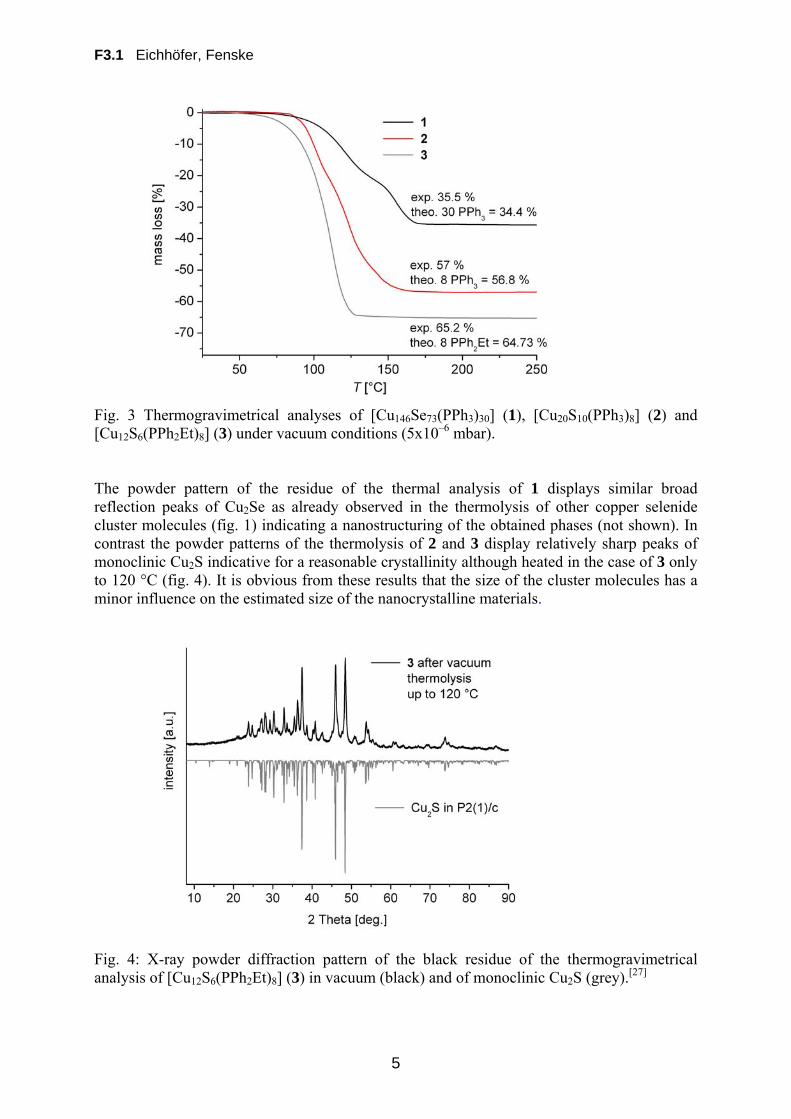
Fig. 3 Thermogravimetrical analyses of [Cu146Se73(PPh3)30] (1), [Cu20S10(PPh3)8] (2) and [Cu12S6(PPh2Et)8] (3) under vacuum conditions (5x10⁻⁶ mbar). The powder pattern of the residue of the thermal analysis of 1 displays similar broad reflection peaks of Cu2Se as already observed in the thermolysis of other copper selenide cluster molecules (fig. 1) indicating a nanostructuring of the obtained phases (not shown). In contrast the powder patterns of the thermolysis of 2 and 3 display relatively sharp peaks of monoclinic Cu2S indicative for a reasonable crystallinity although heated in the case of 3 only to 120 °C (fig. 4). It is obvious from these results that the size of the cluster molecules has a minor influence on the estimated size of the nanocrystalline materials.
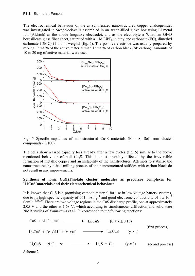
Fig. 4: X-ray powder diffraction pattern of the black residue of the thermogravimetrical analysis of [Cu12S6(PPh2Et)8] (3) in vacuum (black) and of monoclinic Cu2S (grey).[27]
F3.1 Eichhöfer, Fenske
6
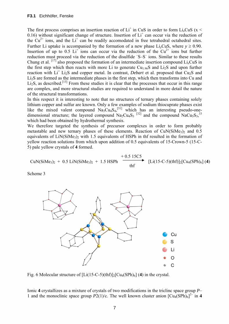
The electrochemical behaviour of the as synthesized nanostructured copper chalcogenides was investigated in Swagelock-cells assembled in an argon-filled glove box using Li metal foil (Aldrich) as the anode (negative electrode), and as the electrolyte a Whatman GF/D borosilicate glass fiber sheet, saturated with a 1 M LiPF6 in ethylene carbonate (EC), dimethyl carbonate (DMC) (1 : 1 in weight) (fig. 5). The positive electrode was usually prepared by mixing 85 wt % of the active material with 15 wt % of carbon black (SP carbon). Amounts of 10 to 20 mg of active material were used. Fig. 5 Specific capacities of nanostructured Cu2E materials (E = S, Se) from cluster compounds (C/100). The cells show a large capacity loss already after a few cycles (fig. 5) similar to the above mentioned behaviour of bulk-Cu2S. This is most probably affected by the irreversible formation of metallic copper and an instability of the nanstructures. Attempts to stabilize the nanostructures by a ball milling process of the nanostructured sulfides with carbon black do not result in any improvements. Synthesis of ionic Cu(I)Thiolato cluster molecules as precursor complexes for `LiCuS´materials and their electrochemical behaviour It is known that CuS is a promising cathode material for use in low voltage battery systems, due to its high specific capacity of 561 mAh g–1 and good electronic conductivity of 1 x 10⁻³ Scm–1.[2,28,29] There are two voltage regions in the CuS discharge profile, one at approximately 2.05 V and the other at 1.68 V, which according to simultaneous diffraction and solid state NMR studies of Yamakawa et al. [30] correspond to the following reactions: Scheme 2
CuS + xLi+ + xe– LixCuS (0 < x ≤ 0.16)
(first process) LixCuS + (y–x)Li+ + (y–x)e–
LiyCuS + 2Li+ + 2e– Li2S + Cu (y 1)
LiyCuS (y 1)
(second process)
F3.1 Eichhöfer, Fenske
7
The first process comprises an insertion reaction of Li+ in CuS in order to form LixCuS (x < 0.16) without significant change of structure. Insertion of Li+ can occur via the reduction of the Cu2+ ions, and the Li+ can be readily accomodated in free tetrahedral octahedral sites. Further Li uptake is accompanied by the formation of a new phase LiyCuS, where y 0.90. Insertion of up to 0.5 Li+ ions can occur via the reduction of the Cu2+ ions but further reduction must proceed via the reduction of the disulfide –S–S– ions. Similar to these results Chung et al. [17] also proposed the formation of an intermediate insertion compound LixCuS in the first step which then reacts with more Li to generate Cu1.96S and Li2S and upon further reaction with Li+ Li2S and copper metal. In contrast, Debart et al. proposed that Cu2S and Li2S are formed as the intermediate phases in the first step, which then transforms into Cu and Li2S, as described.[13] From these studies it is clear that the processes that occur in this range are complex, and more structural studies are required to understand in more detail the nature of the structural transformations. In this respect it is interesting to note that no structures of ternary phases containing solely lithium copper and sulfur are known. Only a few examples of sodium thiocuprate phases exist like the mixed valent compound Na3Cu4S4,
[31] which has an interesting pseudo-one-dimensional structure; the layered compound Na2Cu4S3
[32] and the compound NaCu5S3,33
which had been obtained by hydrothermal synthesis. We therefore targeted the synthesis of precursor complexes in order to form probably metastable and new ternary phases of these elements. Reaction of CuN(SiMe3)2 and 0.5 equivalents of LiN(SiMe3)2 with 1.5 equivalents of HSPh in thf resulted in the formation of yellow reaction solutions from which upon addition of 0.5 equivalents of 15-Crown-5 (15-C-5) pale yellow crystals of 4 formed.
Scheme 3 Fig. 6 Molecular structure of [Li(15-C-5)(thf)]2[Cu4(SPh)6] (4) in the crystal. Ionic 4 crystallizes as a mixture of crystals of two modifications in the triclinc space group P–1 and the monoclinic space group P2(1)/c. The well known cluster anion [Cu4(SPh)6]
2– in 4
CuN(SiMe3)2 + 0.5 LiN(SiMe3)2 + 1.5 HSPh thf
[Li(15-C-5)(thf)]2[Cu4(SPh)6] (4) + 0.5 15C5
F3.1 Eichhöfer, Fenske
8
has been synthesized and structurally characterized before with various other counterions like NMe4
+ [34] and PPh4+ [35]for example (Fig. 6). However no synthesis and structure has been
reported for a lithium salt. The adamantoid cluster cage is composed of four copper atoms which are bridged by six 2-SPh ligands to give a distorted trigonal planar coordination around the copper atoms. Cu–S distances are found to range from 225.3 – 232.6 pm and S–Cu–S angles display values from 104.48 to 137.55°. As expected bond length and angles are quite similar for the triclinic as well as monoclinic structure and are comparable to those found in literature for structures with other counterions. In similar reaction procedures we also succeeded in synthesizing the analogous cluster salts 5 and 6 comprising as a coordinating ligand around the lithium counterions the ethers dme or diglyme.
Scheme 4 Due to twinning problems the crystals were not suitable for single crystal X-ray analysis. However, C,H elemental analysis confirms the general composition while the composition of the anion was proven by ESI-TOF mass spectrometry to give similar mass patterns for 5 and 6 as observed for the crystallographily characterized 4. Fig. 7 Thermogravimetrical analyses of [Li(15-C-5)(thf)]2[Cu4(SPh)6] (4), [Li(diglyme)2]2[Cu4(SPh)6] (5) and [Li(dme)3]2[Cu4(SPh)6] (6) under vacuum conditions (5x10⁻⁶ mbar). Thermal gravimetric analysis of the cluster molecules 4 – 6 under vacuum conditions (5x10–
6 mbar) reveal that the ligands are cleaved in two step processes upon formation of a black residue. NMR data of the cleaved products suggest the cleavage of the ether ligands as well as SPh2 molecules (fig. 7). The experimental mass loss agrees for 4 and 5 with the calculated mass loss according to scheme 5 (4: calc. 75.8 found 74.7 %, 5: calc. 75.1 found 75.3 %) while for 6 the experimental mass loss (71.3 %) is by 4 % lower than the calculated one (75.1
CuN(SiMe3)2 + 0.5 LiN(SiMe3)2 + 1.5 HSPh
dme
[Li(diglyme)2]2[Cu4(SPh)6] (5) diglyme
[Li(dme)3]2[Cu4(SPh)6] (6)
F3.1 Eichhöfer, Fenske
9
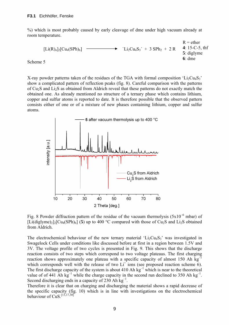
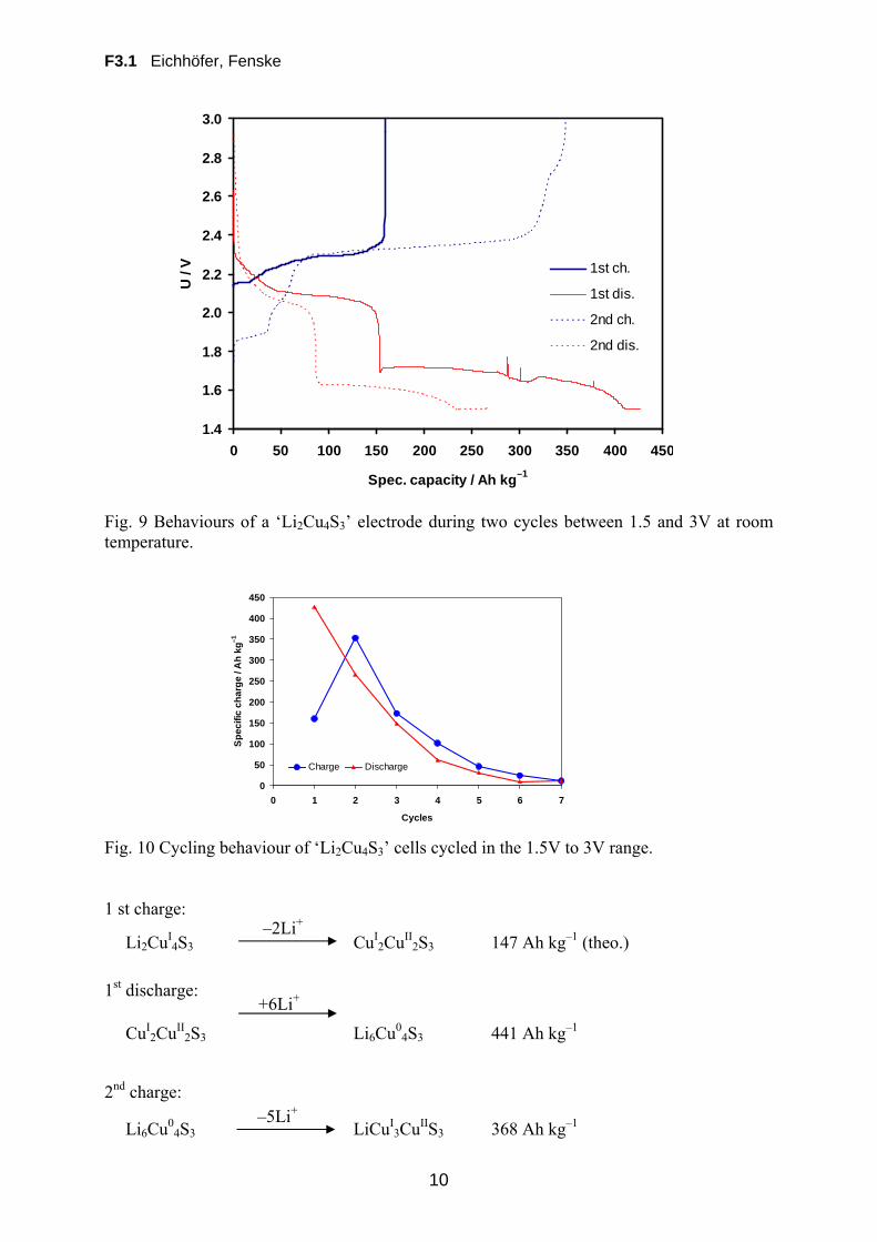
%) which is most probably caused by early cleavage of dme under high vacuum already at room temperature. Scheme 5 X-ray powder patterns taken of the residues of the TGA with formal composition ‘Li2Cu4S3’ show a complicated pattern of reflection peaks (fig. 8). Careful comparison with the patterns of Cu2S and Li2S as obtained from Aldrich reveal that these patterns do not exactly match the obtained one. As already mentioned no structure of a ternary phase which contains lithium, copper and sulfur atoms is reported to date. It is therefore possible that the observed pattern consists either of one or of a mixture of new phases containing lithium, copper and sulfur atoms. Fig. 8 Powder diffraction pattern of the residue of the vacuum thermolysis (5x10⁻⁶ mbar) of [Li(diglyme)2]2[Cu4(SPh)6] (5) up to 400 °C compared with those of Cu2S and Li2S obtained from Aldrich. The electrochemical behaviour of the new ternary material ‘Li2Cu4S3’ was investigated in Swagelock Cells under conditions like discussed before at first in a region between 1.5V and 3V. The voltage profile of two cycles is presented in Fig. 9. This shows that the discharge reaction consists of two steps which correspond to two voltage plateaus. The first charging reaction shows approximately one plateau with a specific capacity of almost 150 Ah kg–1 which corresponds well with the release of two Li+ ions (see proposed reaction scheme 6). The first discharge capacity of the system is about 410 Ah kg–1 which is near to the theoretical value of of 441 Ah kg–1 while the charge capacity in the second run declined to 350 Ah kg–1. Second discharging ends in a capacity of 230 Ah kg–1. Therefore it is clear that on charging and discharging the material shows a rapid decrease of the specific capacity (fig. 10) which is in line with investigations on the electrochemical behaviour of CuS.[13,17,30]
[Li(R)n]2[Cu4(SPh)6] `Li2Cu4S3´ + 3 SPh2 + 2 R
R = ether 4: 15-C-5, thf 5: diglyme 6: dme
F3.1 Eichhöfer, Fenske
10
Fig. 9 Behaviours of a ‘Li2Cu4S3’ electrode during two cycles between 1.5 and 3V at room temperature. Fig. 10 Cycling behaviour of ‘Li2Cu4S3’ cells cycled in the 1.5V to 3V range. 1 st charge: 1st discharge: 2nd charge:
Li2CuI4S3
–2Li+ CuI
2CuII2S3 147 Ah kg–1 (theo.)
CuI2CuII
2S3
+6Li+
Li6Cu04S3 441 Ah kg–1
Li6Cu04S3
–5Li+ LiCuI
3CuIIS3 368 Ah kg–1
1.4
1.6
1.8
2.0
2.2
2.4
2.6
2.8
3.0
0 50 100 150 200 250 300 350 400 450
Spec. capacity / Ah kg–1
U /
V 1st ch.
1st dis.
2nd ch.
2nd dis.
0
50
100
150
200
250
300
350
400
450
0 1 2 3 4 5 6 7
Cycles
Sp
ec
ific
ch
arg
e /
Ah
kg
–1
Charge Discharge
F3.1 Eichhöfer, Fenske
11
2nd discharge Scheme 6 The major source of capacity fading in similar CuS/Li2S cells was identified to be due to the irreversibility of the oxidation of Cu2S with further Li+ to yield copper metal and Li2S (second process in scheme 6). In addition it is known that Li2S formed during the first discharge reaction and Li2Sx (x > 1, lithium polysulfide) can dissolve in the electrolyte.[36,37]
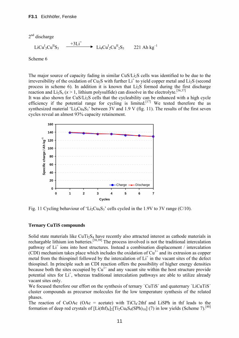
It was also shown for CuS/Li2S cells that the cycleability can be enhanced with a high cycle efficiency if the potential range for cycling is limited.[17] We tested therefore the as synthesized material ‘Li2Cu4S3’ between 3V and 1.9 V (fig. 11). The results of the first seven cycles reveal an almost 93% capacity retainement. Fig. 11 Cycling behaviour of ‘Li2Cu4S3’ cells cycled in the 1.9V to 3V range (C/10). Ternary CuTiS compounds Solid state materials like CuTi2S4 have recently also attracted interest as cathode materials in rechargable lithium ion batteries.[38,39] The process involved is not the traditional intercalation pathway of Li+ ions into host structures. Instead a combination displacement / intercalation (CDI) mechanism takes place which includes the oxidation of Cu1+ and its extrusion as copper metal from the thiospinel followed by the intercalation of Li+ in the vacant sites of the defect thiospinel. In principle such an CDI reaction offers the possibility of higher energy densities because both the sites occupied by Cu1+ and any vacant site within the host structure provide potential sites for Li+, whereas traditional intercalation pathways are able to utilize already vacant sites only. We focused therefore our effort on the synthesis of ternary `CuTiS´ and quaternary `LiCuTiS´ cluster compounds as precursor molecules for the low temperature synthesis of the related phases. The reaction of CuOAc (OAc = acetate) with TiCl4·2thf and LiSPh in thf leads to the formation of deep red crystals of [Li(thf)4]2[Ti2Cu8S4(SPh)10] (7) in low yields (Scheme 7).[40]
LiCuI3CuIIS3
+3Li+ Li4CuI
2CuII2S3 221 Ah kg–1
0
20
40
60
80
100
120
140
160
0 1 2 3 4 5 6 7
Cycles
Sp
ec
ific
ch
arg
e /
Ah
kg
–1
Charge Discharge

F3.1 Eichhöfer, Fenske
12
Due to virtually identical X-ray structure factors of chlorine and sulphur, the X-ray structural analysis only reveals the formula [Li(thf)4]2[Ti2Cu8X4(SPh)10] (X = Cl and/or S), while the exact structural formula of 7 was determined with the help of electronic structure calculations by Nedko Debrov in the group of Reinhard Ahlrichs. Scheme 7
Compound 7 crystallizes in the triclinic space group P–1. A view of the centrosymmetric molecular structure of the dianion in 7 is shown in Figure 12. All titanium atoms are coordinated by five sulphur atoms in a distorted square-pyramidal geometry. The µ4-S
2– atoms bridge two titanium atoms and two copper atoms fairly symmetrically with Ti–S bonds (238.4 to 247.7 pm) significant longer than those in the apical position (Ti–S: 223.7 pm) of the distorted square-based pyramidal geometry. All copper atoms are coordinated by three sulphur atoms (220.6 – 230.7 pm) in a distorted trigonal planar fashion (angle S–Cu–S: 359.62 – 360°). The µ2-S–Ti bonds (Ti–S: 245.4, 247.7 pm) are in the range of those which were found in [CpTi(SCH2CH2S)2CuPMe3].
[41] The copper-titanium distances (CuTi: 277.7 – 278.8) are comparable to those found for example in [(Cp2Ti(SCH2CH3)2TiCp2)CuL]PF6 (L = PPh3 and P(C6H11)3)
[42] (CuTi: 280.3 pm) and [Ti2Cu2S4Cp2(PPh3)2]
[43] (CuTi: 280.93 – 283.2). Those relatively short distances were attributed to result from Cu(d10)Ti(d0) dative bonding interactions. Quantum chemical calculations on 7 done by Nedko Debrov in the group of Reinhard Ahlrichs however suggest that there are no evidences for d10d0 dative bonding interactions in these compounds. Fig. 12 Molecular structure of the dianion [Ti2Cu8S4(SPh)10]
2–in the crystal structure of 7 (50 % ellipsoid) In much better yields we were able to prepare the mixed titanium(IV) / copper(I) trinuclear thiolate cluster complexes [Li(15-C-5)(thf)]2[TiCu2(SPh)8] (8) and [TiCu2(SPh)6(PPh3)] (9) which were synthesized by the reaction of CuCl and TiCl4•2thf with LiSPh in THF at room temperature (Scheme 8). Addition of either 2 eq. of 15-Crown-5 at –15 °C or 2 eq.of PPh3 at
TiCl4▪2thf + CuOAc + 5 LiSPh [Li(thf)4]2[Ti2Cu8S4(SPh)10] (7)

F3.1 Eichhöfer, Fenske
13
rt to the dark-lilac reaction mixtures afforded the crystallisation of dark violet 8 and almost black crystals of 9 respectively. Scheme 8. Ionic 8 crystallizes in the monoclinic space group P21/n (table 3). The molecular structure of the cluster anion [Cu2Ti(SPh)8]
2– in 8 is shown in figure 1. There is an inversion center at the titanium atom and 8 can be viewed as consisting of an distorted octahedral Ti sharing parallel faces with two copper centred tetrahedra. Six of the thiolato ligands act as 2-bridges (Cu–S–Ti: 70.24 – 70.828(18) °) at the corners of the shared faces while two others act as terminal ligands coordinated to the copper atoms. Ti–S bond distances (245.7 – 248.13(8) pm) are shorter than those found in ocathedral [Ti(SPh)6]
2– [44] (255.3 – 258.5(3) pm) and in between values found for [Ti2(SPh)9]
– [45] (232.40 – 254.34 (17) pm) while Cu–S distances (2-SPh–Cu: 234.38 – 236.42(7) pm, 1-SPh–Cu: 223.13(7) pm) are slightly longer than those found for example in [Cu4(SPh)6]
2– (Cu–S: 224.5 – 230.6 pm).[46] While the octahedral thiolate coordination around titanium is only moderately distorted (S–Ti–S: 86.737 – 93.262(19) °), copper sits in a strongly distorted tetrahedral environment (S–Cu–S: 91.67 – 130.44(3) °). The copper-titanium distance (CuTi: 278.78(5) pm) is comparable to those found in [Ti2Cu8S4(SPh)10]
2–.[40] Fig. 13 Molecular structure of [Li(15-C-5)(thf)]2[TiCu2(SPh)8] (8) in the crystal.
CuCl + TiCl4•2thf + 8 LiSPh
thf
[Li(15-C-5)(thf)]2
[TiCu2(SPh)8]
[TiCu2(SPh)6(PPh3)2] (9)
+ 2 PPh3
thf + 2 eq. 15-C-5
(8)
F3.1 Eichhöfer, Fenske
14
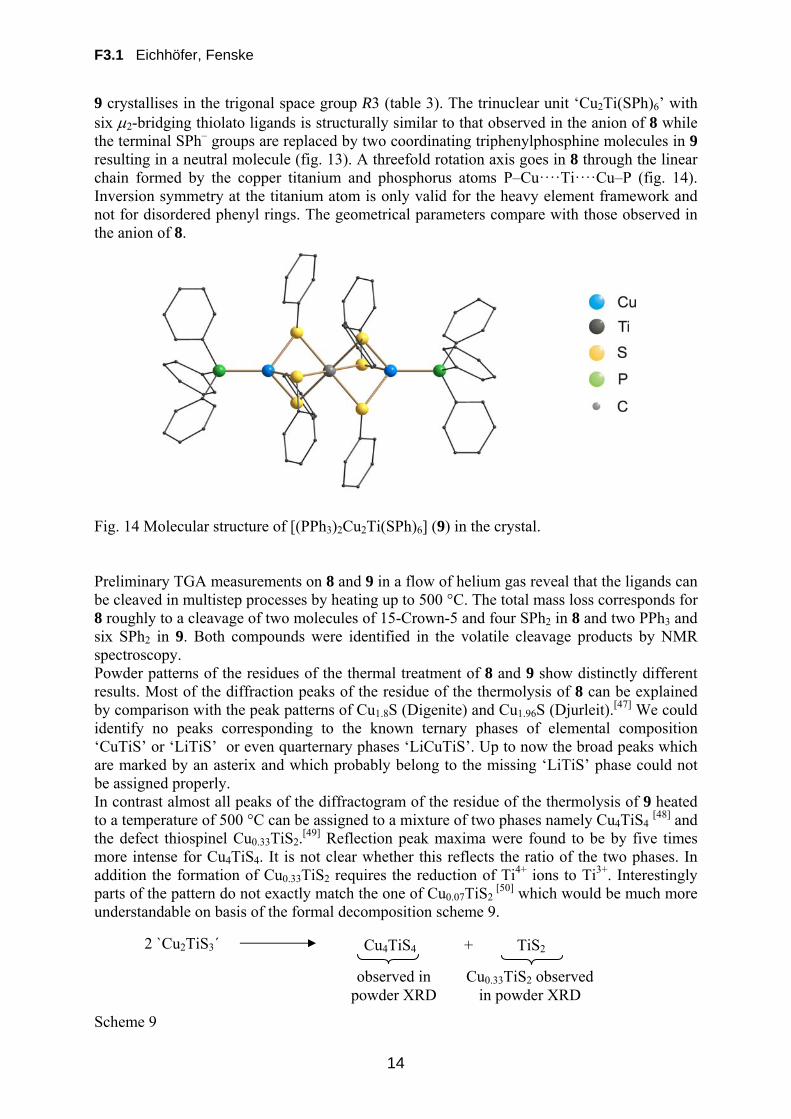
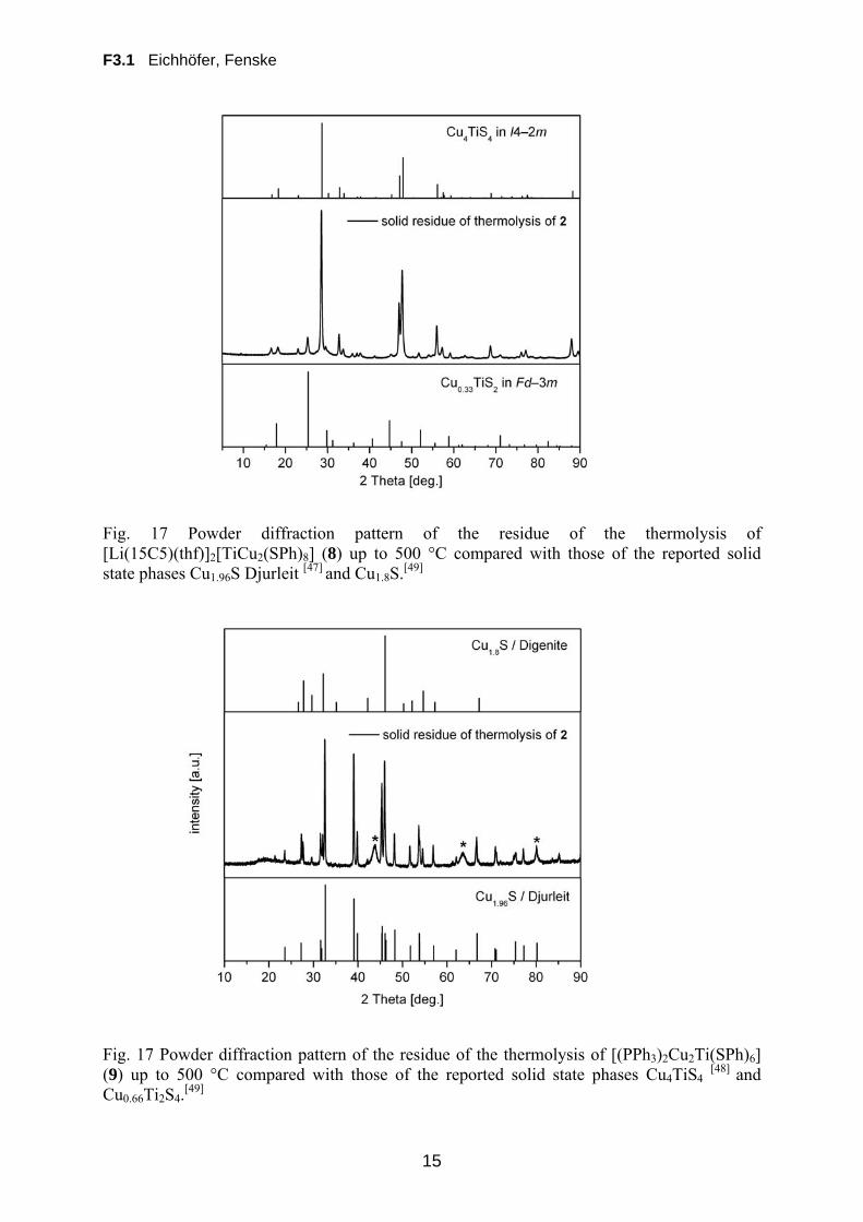
9 crystallises in the trigonal space group R3 (table 3). The trinuclear unit ‘Cu2Ti(SPh)6’ with six 2-bridging thiolato ligands is structurally similar to that observed in the anion of 8 while the terminal SPh– groups are replaced by two coordinating triphenylphosphine molecules in 9 resulting in a neutral molecule (fig. 13). A threefold rotation axis goes in 8 through the linear chain formed by the copper titanium and phosphorus atoms P–Cu····Ti····Cu–P (fig. 14). Inversion symmetry at the titanium atom is only valid for the heavy element framework and not for disordered phenyl rings. The geometrical parameters compare with those observed in the anion of 8. Fig. 14 Molecular structure of [(PPh3)2Cu2Ti(SPh)6] (9) in the crystal. Preliminary TGA measurements on 8 and 9 in a flow of helium gas reveal that the ligands can be cleaved in multistep processes by heating up to 500 °C. The total mass loss corresponds for 8 roughly to a cleavage of two molecules of 15-Crown-5 and four SPh2 in 8 and two PPh3 and six SPh2 in 9. Both compounds were identified in the volatile cleavage products by NMR spectroscopy. Powder patterns of the residues of the thermal treatment of 8 and 9 show distinctly different results. Most of the diffraction peaks of the residue of the thermolysis of 8 can be explained by comparison with the peak patterns of Cu1.8S (Digenite) and Cu1.96S (Djurleit).[47] We could identify no peaks corresponding to the known ternary phases of elemental composition ‘CuTiS’ or ‘LiTiS’ or even quarternary phases ‘LiCuTiS’. Up to now the broad peaks which are marked by an asterix and which probably belong to the missing ‘LiTiS’ phase could not be assigned properly. In contrast almost all peaks of the diffractogram of the residue of the thermolysis of 9 heated to a temperature of 500 °C can be assigned to a mixture of two phases namely Cu4TiS4
[48] and the defect thiospinel Cu0.33TiS2.
[49] Reflection peak maxima were found to be by five times more intense for Cu4TiS4. It is not clear whether this reflects the ratio of the two phases. In addition the formation of Cu0.33TiS2 requires the reduction of Ti4+ ions to Ti3+. Interestingly parts of the pattern do not exactly match the one of Cu0.07TiS2
[50] which would be much more understandable on basis of the formal decomposition scheme 9. Scheme 9
2 `Cu2TiS3´ Cu4TiS4 + TiS2
observed in powder XRD
Cu0.33TiS2 observed in powder XRD
F3.1 Eichhöfer, Fenske
15
Fig. 17 Powder diffraction pattern of the residue of the thermolysis of [Li(15C5)(thf)]2[TiCu2(SPh)8] (8) up to 500 °C compared with those of the reported solid state phases Cu1.96S Djurleit [47] and Cu1.8S.[49]
Fig. 17 Powder diffraction pattern of the residue of the thermolysis of [(PPh3)2Cu2Ti(SPh)6] (9) up to 500 °C compared with those of the reported solid state phases Cu4TiS4
[48] and Cu0.66Ti2S4.
[49]
F3.1 Eichhöfer, Fenske
16
References [1] J. M. Tarascon, M. Armand, Nature 414, 359 (2001) and references therein. [2] J. G. Gabano, V. Dechenaux, G. Gerbier, J. Electrochem. Soc., 119, 459 (1972). [3] M. Armand, in: W. van Goll (Ed.), New Electrode Materials in Fast Ion Transports in Solids, Amsterdam, Holland, 1973. [4] B. C. H. Steele, in W. Van Goll (Ed.), Chemical diffusion in Fast Ion Transports in Solids, Amsterdam, Holland, 1973. [5] M. S. Whittingham, Science, 192, 1126 (1976). [6] M. S. Whittingham, Prog. Solid State Chem. 12, 41 (1978) [7] G. L. Hendriksen, A. N. Jansen, in Handbook of batteries, (Eds: D. Linden, T. B. Reddy), McGraw-Hill, New York 2002. [8] J. T. Kummer, N. Weber, SAE Trans. 76, 88 (1968). [9] R. D. Rauh, K. M. Abraham, G. F. Pearson, J. K. Suprenant, S. B. Brummer, J. Electrochem. Soc. 126, 523, (1979). [10] H. Yamin, E. Peled, J. Power Sources 9, 281 (1983). [11] Y. V. Mikhaylik, J. R. Aldrige, J. Electrochem. Soc. 151, A1969 (2004). [12] S. Kim, Y. J. Jung, S. J. Park, J. Power Sources 152, 272 (2005). [13] A. Debart, L. Dupont, R. Patrice, J. M. Tarascon, Solid State Sci. 8, 640, (2006). [14] F. Bonino, M. Lazzari, B. Rivolta, B. Scrosati, J. Electrochem. Soc. 131, 1498 (1984). [15] A. Timmons, J. R. Dahn, J. Electrochem. Soc. 153, A1206 (2006). [16] W. Dampier, J. Electrochem. Soc. 128, 2501 (1981). [17] J. S. Chung, H. J. Sohn, J. Power Sources, 108, 226 (2002). [18] M. Hughes, N. A. Hampson, S. Karunathilaka, J. Power Sources, 12, 83 (1984). [19] A. Hayashi, T. Ohtomo, F. Mizuno, K. Tadanaga, M. Tasumisago, Electrochim. Acta, 50, 893 (2004). [20] K. Takada, K. Iwamoto, S. Kondo, Solid State Ionics 117, 273 (1999). [21] B. C. Kim, K. Takada, N. Ohta, Y. Seino, L. Q. Zhang, H. Wada, T. Sasaki, Solid State Ionics, 176, 2383,(2005) [22] S. C. Han, K. W. Kim, H. J. Ahn, J. H. Ahn, J. Y. Lee, J. Alloys Compd., 361, 247 (2003). [23] S. Indris, J. Cabana, O. J. Rutt, S. J. Clarke, C. P. Grey, J. Am. Chem. Soc. 128, 13354 (2006). [24] S. Dehnen, A. Eichhöfer, D. Fenske, Chalcogen-Bridged Copper Clusters, Eur. J. Inorg. Chem. 279, (2002). [25] D. Cave, J. F. Corrigan, A. Eichhöfer, D. Fenske, C. M. Kowalchuk, H. Rösner, P. Scheer, Investigation of the Thermal Properties of a Series of Copper Selenide Cluster Molecules, J. Cluster Sci. 18(1), 157 – 172, (2007). [26] in Powder diffraction file PDF-2 Database Sets 1 – 85, 1993, International Center for Diffraction Data, Newtown Square USA, File number 27-1131; A. L. N. Stevels, Philips Res. Rep. Suppl. 9, 39 (1969). [27] H.T. Evans, Jr., Zeitschrift fuer Kristallographie 150, 299 (1979). [28] K. Okamoto, S. Kawai, Jpn. J. Appl. Phys. 12(8), 1130 (1973).
F3.1 Eichhöfer, Fenske
17
[29] A. J. Etienne, J. Electrochem. Soc. 117(7), 870 (1970). [30] N. Yamakawa, M. Jiang, C. P. Grey, Chem. Mater. 21, 3162 (2009). [31] Chr. Burschka, Z. Naturforsch. Teil B, 34, 396 (1979). [32] G. Savelsberg, H. Schäfer, Mater. Res. Bull. 16, 1291 (1981). [33] H. Effenberger, F. Pertlik, Monatsh. Chem. 116, 921, (1985). [34] I. G. Dance, J. C. Calabrese Inorg. Chim. Acta, 19, L41 (1976). [35] D. Coucouvanis, C. N. Murphy, S. K. Kanodia, Inorg. Chem. 37, 168 (1998). [36] R. D. Rauh, K. M. Abraham, G. F. Pearson, J. K. Surprenant, S. B. Brummer, J. Electrochem. Soc. 126, 523 (1979). [37] E. Peled, A. Gorenshtein, M. Segal, Y. Sternberg, J. Power Sources, 26, 269 (1989). [38] V. Bodenez, L. Dupont, M. Morcette, C. Surcin, D. W. Murphy, J.-M. Tarascon, Chem. Mater. 18, 4278 (2006). [39] A. C. W. James, J. B. Goodenough, J. Solid State Chem. 77, 356 (1988). [40] H. Sommer, N. Drebov, A. Eichhöfer, R. Ahlrichs, D. Fenske, Syntheses, structures and theoretical investigations of [Li(thf)4]2[Ti2Cu8S4(SPh)10] and [Ti2Ag6S6Cl2(PPhiPr2)6], Eur. J. Inorg. Chem. 28, 4329 (2009). [41] T. T. Nadasdi, D. W. Stephan, Inorg. Chem. 33, 1532 (1994). [42] T. A. Wark, D. W. Stephan, Inorg. Chem. 26, 363 (1987). [43] T. Amemiya, S. Kuwata, M. Hidai, Chem. Commun. 711 (1999). [44] J. T. Kim, J. W. Park, S. M. Koo, Polyhedron, 1139 (2000). [45] C. Puke, K. Schmengler, K. Kirschbaum, O. Conrad, D. M. Giolando, Acta Crystallogr., Sect. C 56, e542 (2000). [46] B. K. Maiti, K. Pal, S. Sarkar, Eur. J. Inorg. Chem. 5548 (2007). [47] Janosi., Acta Crystallogr., 17, 311, (1964). [48] K.O. Klepp, D. Gurtner, J. Alloys Compds., 243, 19 (1996). [49] T. Kusawake, Y. Takahashi, M. Y. Wey, K. I. Ohshima, J. Phys. Cond. Matter, 13, 9913 (2001). [50] A.C.W.P. James, J.B. Goodenough, N.J. Clayden, P.M. Banks, Mat. Res. Bull. 24, 143 (1989).
![Transition Metal Complexes of Diazenes, XVII [1] Reactions ...zfn.mpdl.mpg.de/data/Reihe_B/37/ZNB-1982-37b-0463.pdf · carbonyls and cyclic diazenes are generally not very stable,](https://static.fdokument.com/doc/165x107/5f6dc150bcd24a7ae93ae75a/transition-metal-complexes-of-diazenes-xvii-1-reactions-zfnmpdlmpgdedatareiheb37znb-1982-37b-0463pdf.jpg)