
NeTEx Technical Report
84
CEN/TC 278 Date: 2015-10 TC 278 WI 00278330 CEN/TC 278 Secretariat: NEN Public transport — Network and Timetable Exchange (NeTEx) — Examples, guidelines and explanatory materials Öffentlicher Verkehr — Netzwerk- und Fahrplan Austausch (NeTEx) Transport Public — Echange des données de réseau et d'horaires (NeTEx) ICS: Descriptors: Document type: Technical Report Document subtype: Document stage: Formal Vote Document language: E C:\Users\pat.gendre\AppData\Local\Temp\Temp1_NeTEx White papers oct15.zip\WI 00278330 FV (E).doc STD Version 2.7g
Transcript of NeTEx Technical Report
CEN/TC 278Date: 2015-10
TC 278 WI 00278330
CEN/TC 278
Secretariat: NEN
Public transport — Network and Timetable Exchange (NeTEx) — Examples, guidelines and explanatory materials
Öffentlicher Verkehr — Netzwerk- und Fahrplan Austausch (NeTEx)
Transport Public — Echange des données de réseau et d'horaires (NeTEx)
ICS:
Descriptors:
Document type: Technical ReportDocument subtype: Document stage: Formal VoteDocument language: EC:\Users\pat.gendre\AppData\Local\Temp\Temp1_NeTEx White papers oct15.zip\WI 00278330 FV (E).doc STD Version 2.7g
TC 278 WI 00278330:2015 (E)
Contents Page
European Foreword.................................................................................................................................................
1 Introduction..................................................................................................................................................1.1 General information...................................................................................................................................1.2 Compatibility with existing standards and recommendations.....................................................1.3 NeTEx exchanged information................................................................................................................1.4 NeTEx exchanging data modality...........................................................................................................1.5 Motivation...................................................................................................................................................1.5.1 Business drivers........................................................................................................................................1.5.2 Technical drivers......................................................................................................................................1.5.3 CEN Standards context............................................................................................................................1.5.4 CEN process and participants................................................................................................................1.5.5 Evolution of EU PT standards and NeTEx..........................................................................................1.6 Term of Use.................................................................................................................................................
2 Scope.............................................................................................................................................................
3 Frequently Asked Questions (FAQ).....................................................................................................3.1 Introduction...............................................................................................................................................3.2 Basic Commercial questions..................................................................................................................3.2.1 Do I have to pay for using NeTEx?........................................................................................................3.2.2 What skills do I need to deploy NeTEx?.............................................................................................3.2.3 What tools are available to support NeTEx?.....................................................................................3.2.4 How do I get new features added to NeTEx?.....................................................................................3.2.5 What is a profile?......................................................................................................................................3.2.6 What if I find a bug in NeTEx?...............................................................................................................3.2.7 How do I get support for my NeTEx development?........................................................................3.3 Basic scope questions..............................................................................................................................3.3.1 Is NeTEx a GIS standard?........................................................................................................................3.3.2 Is NeTEx a database?................................................................................................................................3.3.3 Is NeTEx for real-time applications?...................................................................................................3.3.4 Can I use NeTEx for Rail?........................................................................................................................3.3.5 Does NeTEx provide web services?.....................................................................................................3.3.6 Does NeTEx cover ticket sales?.............................................................................................................3.3.7 Can I use NeTEx for mobile applications?.........................................................................................3.4 Pros and Cons questions.........................................................................................................................3.4.1 What are the advantages of using NeTEx?.........................................................................................3.4.2 How can NeTEx reduce development costs?.....................................................................................3.4.3 How can NeTEx increase capability and improve design quality?.............................................3.4.4 How can NeTEx simplify my software application development?.............................................3.4.5 How can NeTEx protect my investment?...........................................................................................3.4.6 What are the disadvantages of using NeTEx?...................................................................................3.4.7 Is NeTEx hard to understand?...............................................................................................................3.4.8 Does increased generality make NeTEx is harder to work with?..............................................3.4.9 Does NeTEx require more computing resources that other standards?.................................3.4.10 Are there missing validity checks in NeTEx ?...................................................................................3.4.11 Is it quick to add new features in NeTEx?..........................................................................................3.5 Further Specific questions of Scope....................................................................................................
2
TC 278 WI 00278330:2015 (E)
3.5.1 Can NeTEx describe journey connection times?..............................................................................3.5.2 Does NeTEx support accessibility?......................................................................................................3.5.3 Can NeTEx handle frequency based services?.................................................................................3.5.4 Can I have different journey timings for different times of day?...............................................3.5.5 Can NeTEx describe zone based fares?...............................................................................................3.5.6 Can I restrict certain products to certain classes of user?...........................................................3.5.7 Can I specify time based constraints on travel?..............................................................................3.5.8 Can I integrate data from different countries with NeTEx?.........................................................3.5.9 Does NeTEx support dynamic/ yield managed pricing?...............................................................3.5.10 Can NeTEx define products for modern e-card based ticketing?...............................................3.5.11 Does NeTEx support Flexible and Demand Responsive Travel?................................................3.5.12 Can I create applications to run in different national Languages?............................................3.5.13 Can I have different version of data for the same element extant at the same time?..........3.5.14 Can I create Network maps with NeTEx?...........................................................................................3.5.15 I have my own classification for Stops/ Lines / etc. Can NeTEx handle this?.........................3.6 Comparison with other standards.......................................................................................................3.6.1 How does NeTEx relate to Transmodel?............................................................................................3.6.2 How does NeTEx relate to IFOPT?........................................................................................................3.6.3 How does NeTEx compare with VDV?.................................................................................................3.6.4 How does NeTEx compare with TransXChange?.............................................................................3.6.5 How does NeTEx compare with NEPTUNE?......................................................................................3.6.6 How does NeTEx compare with NOPTIS?..........................................................................................3.6.7 How does NeTEx compare with IFM?..................................................................................................3.6.8 How does NeTEx compare with BISON ?............................................................................................3.6.9 How does NeTEx compare with the Taap/TSI standards?...........................................................3.6.10 How does NeTEx compare with GTFS?...............................................................................................
4 NeTEx covered areas description........................................................................................................4.1 General areas.............................................................................................................................................4.2 Specific functional areas.........................................................................................................................
Annex A (informative) Getting Started...........................................................................................................A.1 Three common use cases........................................................................................................................A.2 Basic Steps...................................................................................................................................................A.2.1 Agreeing a profile.....................................................................................................................................A.2.2 Choosing a Version frame.......................................................................................................................A.3 Implementing a NeTEx System.............................................................................................................A.3.1 Implementation Technology.................................................................................................................A.3.2 Implementation of NeTEx interfaces..................................................................................................A.3.3 Version Lifecycle for Data Elements...................................................................................................A.3.4 Validation & Conformance of XML documents................................................................................A.3.5 Schema versions and schema compatibility.....................................................................................A.4 Resources....................................................................................................................................................A.5 NeTEx CEN Technical specifications,..................................................................................................A.6 NeTEx UML Models...................................................................................................................................A.7 NeTEx XML Schema..................................................................................................................................A.8 NeTEx WSDL Bindings.............................................................................................................................A.9 Tools & Technology..................................................................................................................................
Annex B (informative) Design Methodology.................................................................................................B.1 Model driven design.................................................................................................................................B.1.1 The Transmodel Conceptual model....................................................................................................B.2 Consistent Terminology..........................................................................................................................B.3 UML Notation..............................................................................................................................................B.4 XML schema................................................................................................................................................
3
TC 278 WI 00278330:2015 (E)
B.4.1 XML Benefits...............................................................................................................................................B.4.2 XML Drawbacks.........................................................................................................................................B.5 Tools & Technology..................................................................................................................................B.6 Modularisation of the framework.......................................................................................................
Annex C (informative) Framework..................................................................................................................C.1 The NeTEx Frameworks..........................................................................................................................4.3 NeTEx framework features....................................................................................................................C.1.1 Versioning...................................................................................................................................................C.1.2 Identifiers, uniqueness of reference and Namespaces..................................................................C.1.3 Responsibility Management..................................................................................................................C.1.4 Summary of GENERIC Framework Components..............................................................................
Annex D (informative) Reusable Components.............................................................................................D.1 The NeTEx Reusable Components.......................................................................................................D.2 Summary of Reusable Components.....................................................................................................D.2.1 Reusable Component types....................................................................................................................D.2.2 General Reusable Component types...................................................................................................D.2.3 Transport Reusable Component types...............................................................................................D.3 Summary of Reusable Data types.........................................................................................................
Annex E (informative) Representing Public Transport Networks in NeTEx.......................................E.1 NeTEx Methodology.................................................................................................................................E.2 Scope.............................................................................................................................................................E.3 Corresponding NeTEx documentation...............................................................................................E.4 Approach.....................................................................................................................................................E.4.1 Reconciling different views of the network......................................................................................E.4.2 Generic concepts.......................................................................................................................................E.5 Basic spatial network aspects...............................................................................................................E.5.1 Routes and work patterns......................................................................................................................E.5.2 Layers...........................................................................................................................................................E.5.3 Geospatial concerns.................................................................................................................................E.5.4 Lines..............................................................................................................................................................E.5.5 Schematic maps.........................................................................................................................................
Annex F (informative) Representing Flexible Networks and Multimodality in NeTEx....................F.1 Scope.............................................................................................................................................................F.2 Corresponding NeTEx documentation...............................................................................................F.3 NeTEx Methodology.................................................................................................................................F.4 Flexible networks.....................................................................................................................................F.4.1 Flexible behaviour of public transport services.............................................................................F.4.2 Defining areas of flexible coverage.....................................................................................................F.4.3 Defining flexible routes...........................................................................................................................F.4.4 Timing of flexible services.....................................................................................................................F.4.5 Information on using services..............................................................................................................F.5 Multimodality.............................................................................................................................................F.5.1 Multimodal network features...............................................................................................................F.5.2 Multimodal stop places...........................................................................................................................F.5.3 Physical versus logical stops.................................................................................................................F.5.4 Multimodal connection possibilities...................................................................................................
Annex G (informative) Support for Accessibility in NeTEx.......................................................................G.1 Scope.............................................................................................................................................................G.2 Corresponding NeTEx documentation...............................................................................................G.3 NeTEx Methodology.................................................................................................................................G.4 Approach.....................................................................................................................................................
4
TC 278 WI 00278330:2015 (E)
G.5 Accessibility of sites.................................................................................................................................G.6 Accessibility and connections...............................................................................................................G.7 Accessibility of navigation paths..........................................................................................................G.8 Accessibility of journeys.........................................................................................................................
Annex H (informative) Representing Timetables in NeTEx.....................................................................H.1 Corresponding NeTEx documentation...............................................................................................H.2 Approach to Timetables in NeTEx.......................................................................................................H.3 The representation of a timetable.......................................................................................................H.3.1 Components to create a timetable.......................................................................................................H.3.2 Components to operate a timetable....................................................................................................H.4 Example of a simple timetable in NeTEx............................................................................................
Annex I (informative) Representing Fares in NeTEx..................................................................................I.1 Scope.............................................................................................................................................................I.2 Functional areas........................................................................................................................................I.2.1 Fare policy specification:........................................................................................................................I.3 Provision of information on fares........................................................................................................I.4 Approach.....................................................................................................................................................I.4.1 Fare structure elements.........................................................................................................................I.4.2 Access rights and Fare products...........................................................................................................I.4.3 Restrictions and conditions...................................................................................................................I.5 Selecting a Fare..........................................................................................................................................I.5.1 Pricing a Fare.............................................................................................................................................I.5.2 Electronic Fare products and NeTEx...................................................................................................
Bibliography.............................................................................................................................................................
5

TC 278 WI 00278330:2015 (E)
European Foreword
This document (TC 278 WI 00278330) has been prepared by Technical Committee CEN/TC 278“Intelligent transport systems”, the secretariat of which is held by NEN.
This document is currently submitted to the Formal Vote.
6
TC 278 WI 00278330:2015 (E)
1 Introduction
1.1General information
NeTEx is a CEN Technical standard dedicated to the exchange of Public Transport scheduled data(network, timetable and fare information) based on:
— Transmodel V5.1 (see [T1], [T1] and [T3]);
— IFOPT (see [I1]);
— SIRI (see [S1], [S2], [S3], [S4], [S5]);
It supports information exchange of relevance to public transport services for passenger informationand AVMS (Automated Vehicle Monitoring Systems). Many NeTEx concepts are taken directly fromTransmodel and IFOPT; the definitions and explanation of these concepts are extracted directly fromthe respective standards and reused in NeTEx, sometimes with further adaptions in order to fit theNeTEx context.
The data exchanges targeted by NeTEx are predominantly oriented towards passenger information andalso for data exchange between transit scheduling systems and AVMS. However it is not restricted tothese purposes, and it can provide an effective solution to many other use cases for transport dataexchange
NeTEx standard is divided into three parts, each covering a functional subset of the CEN Transmodel forPublic Transport Information:
— Part 1 describes the Public Transport Network topology (see [N1]);
— Part 2 describes Scheduled Timetables (see [N2]);
— Part 3 covers Fare information (see [N3]).
NeTEX is intended to be a general purpose XML format designed for the efficient, updateable exchangeof complex transport data among distributed systems. This allows the data to be used in modern webservices based architectures and to support a wide range of passenger information and operationalapplications
Most public transport modes are taken into account by NeTEx, including train, bus, coach, metro,tramway, ferry, and their submodes. Moreover, it is possible to describe airports and air journeys, butthere has not been any specific consideration of any additional provisions that apply especially to airtransport.
Whilst there are a number of existing standards available for Timetables, NeTEx is the firstsystematically engineered standard that also covers multimodal Fares.
1.2Compatibility with existing standards and recommendations
The concepts covered in NeTEx that relate in particular to long-distance train travel include;
— rail operators and related organizations;
— stations and related equipment's;
7
TC 278 WI 00278330:2015 (E)
— journey coupling and journey parts;
— train composition and facilities;
— planned passing times;
— timetable versions and validity conditions.
In the case of long distance train the NeTEx takes into account the requirements formulated by the ERA(European Rail Agency) – TAP/TSI (Telematics Applications for Passenger/ Technical Specification forInteroperability), entered into force on 13 May 2011 as the Commission Regulation (EU No 454/2011),based on UIC directives.
As regards the other exchange protocols, a formal compatibility is ensured with TransXChange (UK),VDV 452 (Germany), NEPTUNE (France), UIC Leaflet, BISON (Netherland) and NOPTIS (Nordic PublicTransport Interface Standard).
The data exchange is possible either through dedicated web services, through data file exchanges, orusing the SIRI exchange protocol as described in Part 2 of the SIRI documentation (see [S2]).
The following documents, in whole or in part, are normatively referenced and are indispensable for itsapplication. For dated references, only the edition cited applies. For undated references, the latestedition of the referenced document (including any amendments) applies.
— EN 15531-1, Public transport - Service interface for real-time information relating to publictransport operations - Part 1: Context and framework (see [S1]);
— EN 15531-2, Public transport - Service interface for real-time information relating to publictransport operations - Part 2: Communications infrastructure (see [S2]);
— EN 15531-3, Public transport - Service interface for real-time information relating to publictransport operations - Part 3: Functional service interfaces (see [S3]);
— CEN/TS 15531-4, Public transport - Service interface for real-time information relating to publictransport operations - Part 4: Functional service interfaces: Facility Monitoring (see [S4]);
— CEN/TS 15531-5, Public transport - Service interface for real-time information relating to publictransport operations - Part 5: Functional service interfaces - Situation Exchange (see [S5]);
— EN 12896, Road transport and traffic telematics - Public transport - Reference data model (see[T1]);
— EN 28701, Intelligent transport systems - Public transport - Identification of Fixed Objects in PublicTransport (see [I1]).
1.3NeTEx exchanged information
NeTEx provides a means to exchange data for passenger information such as stops, routes timetablesand fares, among different computer systems, together with related operational data. It can be used tocollect and integrate date from many different stakeholders, and to reintegrate it as it evolves throughsuccessive versions.
All three parts covered by NeTEx use the same framework of reusable components, versioningmechanisms, validity conditions, global identification mechanisms, etc., defined in a NeTEx framework
8

TC 278 WI 00278330:2015 (E)
in Part1. NeTEx also includes, container elements called “version frames” to group data into coherentsets for efficient exchange.
NeTEx schema can thus be used to exchange:
— Public Transport schedules including stops, routes, departures times / frequencies, operationalnotes, and map coordinates.
— Routes with complex topologies such as circular routes, cloverleaf and lollipops, and complexworkings such as short working and express patterns. Connections with other services can also bedescribed
— The days on which the services run, including availability on public holidays and other exceptions.
— Composite journeys such as train journeys that merge or split trains
— Information about the Operators providing the service.
— Additional operational information, including, positioning runs, garages, layovers, duty crews,useful for AVL and on-board ticketing systems.
— Data about the Accessibility of services to passengers with restricted mobility.
— Data is versioned with management metadata allowing updates across distributed systems
— Fare structures, (flat fares, point to point fares, zonal fares)
— Fare products (Single tickets, return tickets, day, and season passses etc)
— Fare prices that apply at specific dates
1.4NeTEx exchanging data modality
Data in NeTEx format is encoded as XML documents that must conform exactly to the defined schema,and conformance can be checked automatically by standard XML validator tools. The schema can alsobe used to create bindings to different programming languages to assist automating part of theimplementation process for creating software that supports NeTEx formats.
In this perspective, a NeTEx service need only to implement those elements of relevance to its businessobjectives – extraneous elements present in the binding can be ignored. Parties using NeTEx for aparticular purpose will typically define a “profile” to identify the elements that must be present and thecode sets to be used to identify them.
Documents in NeTEx format are computer files that can be exchanged by a wide variety of protocols(http, FTP, email, portable media, etc). NeTEx publication documents can be used to define files suitablefor the bulk exchange of XML documents representing whole data sets (for example all the timetablesfor an operator).
In addition, a SIRI based NeTEx protocol is specified for use by online web services. It defines NeTExrequest and response messages that can be used to request and return data in NeTEx format, and alsopublish/subscribe messages for push distribution. The responses return a NeTEx XML document thatsatisfies the request criteria (and also conforms to the NeTEx schema). There is a WSDL binding for thisNeTEx service to make it easy to implement services.
9
TC 278 WI 00278330:2015 (E)
NeTEx XML thus serialises complex PT models into a standard flat file format that can be processedcheaply and efficiently using mainstream modern computer technologies.
1.5Motivation
1.5.1 Business drivers
Modern public transport services rely increasingly on computerised information systems for passengerinformation; for example for timetables, for real time data and for ticketing. The increased use of onlineengines and electronic ticket products in particular requires the representation of timetables, productsand fares as digitalised data sets. Such data is typically both inherently complex (since the real-worlddomains it describes are complex) - and subject to a complex workflow. Data is typically assembledfrom many different stakeholders with different responsibilities (for stops, timetables, real time, fareproducts, pricing etc ) and is continually changing - at intervals ranging from the intermittent periodicchange of network and timetable data, to the second by second changes of real-time systems.Standardisation seeks to provide effective data models that both capture these complex domains asreusable components and to support a workflow that involves continuous integration and validation ofdata under many different possible configurations of participants.
Well-defined, open interfaces therefore have a crucial role in improving the economic and technicalviability of Public Transport Information systems. Using standardised interfaces, systems can beimplemented as discrete pluggable modules that can be chosen from a wide variety of suppliers in acompetitive market, rather than as monolithic proprietary systems from a single supplier. Furthermore,individual functional modules can be replaced or evolved, without unexpected breakages of obscurelydependent function. Interfaces also allow the systematic automated testing of each functional module,vital for managing the complexity of increasing large and dynamic systems.
1.5.2 Technical drivers
Increasing complexity is itself is a barrier to the development and uptake of systems, and it is notuncommon to find that organisations develop multiple and sometimes conflicting models to handledifferent aspects of their business processes, and also to find that the difficulty of changing the systemimpairs development of the business. Because PT data sets are complex and shared by so manyparticipant , they are especially hard to change and they thus represent a strategic investment. It is thusis important to design them for long term use so that they are expressive enough to capture businessrequirements and flexible enough to evolve to meet to changing business requirements and use.
1.5.3 CEN Standards context
NeTEx has been developed under the aegis of CEN and is the most recent development stage in overfifteen years work to systemise and harmonize European passenger information data. The work drawson a number of existing national standards applying systematic principles of information architectureto construct flexible models that correctly separate the different concerns of representing andmanaging data. The keystone is the Transmodel standard(see [T1]), a conceptual model which namesand represents PT info concepts for a wide set of functional areas and can be used to compare andunderstand different models. Transmodel project outputs have been used both to underpin a number ofCEN concrete data standards such as SIRI and IFOPT, and to rationalise national standards to allow forharmonisation and interoperability. Transmodel has been used to develop NeTEx and is itself beingupdated to include NeTEx additions. Whilst there are a number of standards available for Timetables,NeTEx is the first systematically engineered standard that also covers multimodal Fares.
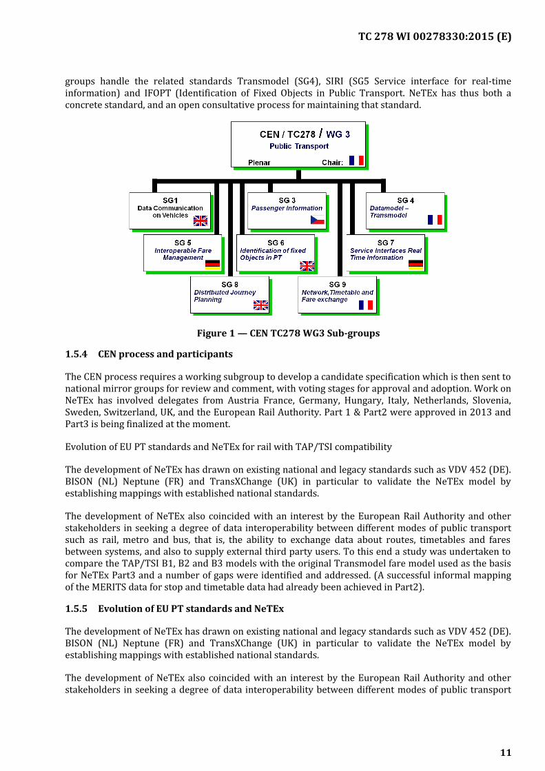
CEN (Comité Européen de Normalisation) is Europe’s standardisation body. It divides its work underinto committees covering different aspects of industry and technology. NeTEx, as a transport standardis formally produced by Technical Committee 278, Work Group 3, Sub Group 9. Other TC278 WG3 sub
10
TC 278 WI 00278330:2015 (E)
groups handle the related standards Transmodel (SG4), SIRI (SG5 Service interface for real-timeinformation) and IFOPT (Identification of Fixed Objects in Public Transport. NeTEx has thus both aconcrete standard, and an open consultative process for maintaining that standard.
Figure 1 — CEN TC278 WG3 Sub-groups
1.5.4 CEN process and participants
The CEN process requires a working subgroup to develop a candidate specification which is then sent tonational mirror groups for review and comment, with voting stages for approval and adoption. Work onNeTEx has involved delegates from Austria France, Germany, Hungary, Italy, Netherlands, Slovenia,Sweden, Switzerland, UK, and the European Rail Authority. Part 1 & Part2 were approved in 2013 andPart3 is being finalized at the moment.
Evolution of EU PT standards and NeTEx for rail with TAP/TSI compatibility
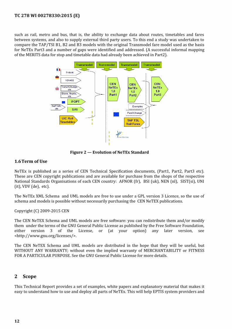
The development of NeTEx has drawn on existing national and legacy standards such as VDV 452 (DE).BISON (NL) Neptune (FR) and TransXChange (UK) in particular to validate the NeTEx model byestablishing mappings with established national standards.
The development of NeTEx also coincided with an interest by the European Rail Authority and otherstakeholders in seeking a degree of data interoperability between different modes of public transportsuch as rail, metro and bus, that is, the ability to exchange data about routes, timetables and faresbetween systems, and also to supply external third party users. To this end a study was undertaken tocompare the TAP/TSI B1, B2 and B3 models with the original Transmodel fare model used as the basisfor NeTEx Part3 and a number of gaps were identified and addressed. (A successful informal mappingof the MERITS data for stop and timetable data had already been achieved in Part2).
1.5.5 Evolution of EU PT standards and NeTEx
The development of NeTEx has drawn on existing national and legacy standards such as VDV 452 (DE).BISON (NL) Neptune (FR) and TransXChange (UK) in particular to validate the NeTEx model byestablishing mappings with established national standards.
The development of NeTEx also coincided with an interest by the European Rail Authority and otherstakeholders in seeking a degree of data interoperability between different modes of public transport
11
TC 278 WI 00278330:2015 (E)
such as rail, metro and bus, that is, the ability to exchange data about routes, timetables and faresbetween systems, and also to supply external third party users. To this end a study was undertaken tocompare the TAP/TSI B1, B2 and B3 models with the original Transmodel fare model used as the basisfor NeTEx Part3 and a number of gaps were identified and addressed. (A successful informal mappingof the MERITS data for stop and timetable data had already been achieved in Part2).
Figure 2 — Evolution of NeTEx Standard
1.6Term of Use
NeTEx is published as a series of CEN Technical Specification documents, (Part1, Part2, Part3 etc).These are CEN copyright publications and are available for purchase from the shops of the respectiveNational Standards Organisations of each CEN country: AFNOR (fr), BSI (uk), NEN (nl), SIST(si), UNI(it), VDV (de), etc).
The NeTEx XML Schema and UML models are free to use under a GPL version 3 Licence, so the use ofschema and models is possible without necessarily purchasing the CEN NeTEX publications.
Copyright (C) 2009-2015 CEN
The CEN NeTEX Schema and UML models are free software: you can redistribute them and/or modifythem under the terms of the GNU General Public License as published by the Free Software Foundation,either version 3 of the License, or (at your option) any later version, see<http://www.gnu.org/licenses/>.
The CEN NeTEX Schema and UML models are distributed in the hope that they will be useful, butWITHOUT ANY WARRANTY; without even the implied warranty of MERCHANTABILITY or FITNESSFOR A PARTICULAR PURPOSE. See the GNU General Public License for more details.
2 Scope
This Technical Report provides a set of examples, white papers and explanatory material that makes iteasy to understand how to use and deploy all parts of NeTEx. This will help EPTIS system providers and
12
TC 278 WI 00278330:2015 (E)
acquirers, providing functional scope, guidelines and terminology explanations needed to implement asystem. It will also ease formalizing the requirements for the context of a procurement process.
3 Frequently Asked Questions (FAQ)
3.1Introduction
In this paragraph a set of Frequently Asked Questions (FAQ) is reported. FAQ are also maintainedupdated in the relevant NeTEx website section (see http://netex-cen.eu/?page_id=111).
3.2Basic Commercial questions
3.2.1 Do I have to pay for using NeTEx?
NeTEx is a CEN standard, the formal documents describing the standard are available as TechnicalSpecifications (TS) from your national standardisation body. A fee in the national currency is chargedfor such documents by each standardisation body. However the actual formats and designs describedby the TS may be used without charge, and without necessarily purchasing the CEN NeTEx publications.You may use the schema and models for free under a GPL license as described on NeTEx web site(http://netex-cen.eu/?page_id=20). This ensures that the IPR is in the public domain and may be safelyconsidered as a long term strategic investment.
3.2.2 What skills do I need to deploy NeTEx?
The NeTEx schema itself is a W3C XML schema, so XML technical skills are typically required to buildapplications to create or process data in NeTEx format. General XML skills can be used to process XMLdocuments containing data in NeTEx format, for example, to run validators or to amend content.
At a design level, NeTEx uses a “Model Driven” approach, that is, the fundamental design is described asa high level conceptual model that tries to represent the problem domain as entities and relationshipsthat have been identified by a set of use cases, many taken from existing systems covering the desiredbusiness scope. To understand the high level model underlying the XML schema (which is valuable forbuilding applications) requires data modelling skills and an understanding of the UML notation. PublicTransport domain knowledge will of course help (additional information availableat http://transmodel-cen.eu/).
3.2.3 What tools are available to support NeTEx?
General purpose XML tools can be used to work with the NeTEx XML schema and XML documents thatconform to it, for example either the proprietary XML SPY (http://www.altova.com/xmlspy.html), orOxygen (http://www.oxygenxml.com/) or see free toolsat http://www.garshol.priv.no/download/xmltools/. A wide variety of mainstream XML tools areavailable to validate XML and to create bindings to specific programming languages (.NET, Java, PHP, C++).
To look at the design models, an interactive UML viewer such as EnterpriseArchitect (http://www.sparxsystems.com/ ) is extremely helpful, although a set of static web pages isalso available.
To import or export transport data in NeTEx format, a number of suppliers are developing support forNeTEx for their existing products. New open source NeTEx products are also being developed such asCHOUETTE (http://www.chouette.mobi/en/). Sample mappings to a variety of national formats (VDV,BISON, etc) as well as GTFS have been developed and are included in the NeTEx standard. Furtherinformation on NeTEx implementations are available at http://netex-cen.eu/?page_id=65.
13
TC 278 WI 00278330:2015 (E)
3.2.4 How do I get new features added to NeTEx?
CEN working groups provide a consensual process to evolve standards and have formal procedures andtimeframes managed through the standards bodies of the European nations. New feature proposals canbe submitted to the NeTEx working group by sending an email at info<at>netex-cen.eu and will beconsidered along with other suggestions for a future enhancement to the standard. Under the CENprocess a New Work Item request is created to manage the enhancements to a specification, with aversioning process to identify sets of changes.
Adding new features specific to country, supplier or any smaller area can be done using NeTExextension mechanisms (Key Value extensions/ Extension Tag). These can also be used to develop newcandidate features ahead of formal incorporation. See also ‘Can I add my own codes to NeTEx’?
3.2.5 What is a profile?
Although NeTEx is a large standard, a NeTEx service needs only to implement the specific elementsrelevant to its business objectives – extraneous elements present in the model can be ignored. Partiesusing NeTEx for a particular purpose will typically define a “profile” to identify the subset of elementsthat must be present, as well as the code sets to be used to identify them. A machine readable form ofthis profile may be created using the NeTEx TYPE OF FRAME element, specifying which elements mustbe present; this can be used to enable automatic validators for local profiles.
Following are some profile examples:
— Network-profile: http://netex-cen.eu/wp-content/uploads/2015/06/Network-profile.pdf
— Timing-profile: http://netex-cen.eu/wp-content/uploads/2015/06/Timing-profile.pdf
— Stop-profile: http://netex-cen.eu/wp-content/uploads/2015/06/Stop-profile.pdf
— Shared-Element-profile:http://netex-cen.eu/wp-content/uploads/2015/06/Shared-Element-profile.pdf
— Stop-Identification-profile:http://netex-cen.eu/wp-content/uploads/2015/06/Stop-Identification-profile.pdf
— Concept-selection-profile:http://netex-cen.eu/wp-content/uploads/2015/06/Concept-selection-profile.pdf
3.2.6 What if I find a bug in NeTEx?
Any issue on NeTEx can be communicated to the working group sending an email at info <at> netex-cen.eu. NeTEx schemas are in GITHUB and corrected versions, identified by an interim version number,can be created if necessary.
3.2.7 How do I get support for my NeTEx development?
Some basic support for NeTEx development can be get sending an email at [email protected].
14
TC 278 WI 00278330:2015 (E)
3.3Basic scope questions
3.3.1 Is NeTEx a GIS standard?
Spatial location is important for a number of NeTEx elements, for example to locate stops, but NeTEx isnot of itself a GIS standard; rather it defines additional public transport related layers of informationthat may be projected onto a GIS data set. Thus for example a typical application such as a JourneyPlanner will seamlessly combine NeTEx data with map data address data to allow a user to plan travelfrom any location to any location.. NeTEx uses a GML based coordinate system to reference GIS data,allowing a wide variety of GIS formats to be used (WS84, National Ordnance Survey Grid, Lambert, etc).This should make it easy to combine NeTEx data with other data sets, and to support different GISreference systems..
NeTEx also includes distinct concepts of topographic place and of administrative jurisdiction – againdistinct from GIS location, but which can be mapped to other systems that give a spatial projection forreference. Thus stops can be located a serving a particular town or region (even as is sometimes thecase for major interchanges, they are not physically contained within the geospatial boundaries).
3.3.2 Is NeTEx a database?
No, NeTEx defines an exchange format to exchange data between systems; it does not constrain theinternal representation used by a given system to store or process the data, nor require the use of aspecific database design. That said, any database supporting NeTEx data will need to havecorresponding elements that can be mapped into the elements in the subset of NeTEx supported.
For more information refer to Transmodel for database modelling (http://transmodel-cen.eu/)
3.3.3 Is NeTEx for real-time applications?
NeTEx can usefully be used to provision systems with the reference data needed to support real-timedata, such as stops, lines, routes, timetables etc, but is not envisaged as a real-time data protocol. Real-time applications typically need to be optimised to exchange the data very quickly, very efficiently andspecific protocols such as CEN SIRI are designed to do this. The NeTEx model can however be used tounderstand how the real-time data content of SIRI messages relates to the NeTEx & Transmodelmodels.
NeTEx model includes additional data elements specifically to support stop and on board real-timesystems, for example the headings to show on a vehicle at each stop, the stop announcements etc, thatare not needed for simple timetable exchange such as by GTFS.
3.3.4 Can I use NeTEx for Rail?
Yes, NeTEx covers stations, networks, timetables and fares for Rail. The development process hasinvolved experts from Rails (ERA, UIC, SNCF, ATOC, etc.) to make sure specific rails requirements aretaken into account. The NeTEx design process included consideration of the B1, B2 and B3 Tap/TSI datamodels for European Rail fares as well as various national urban and suburban rail systems. NeTExincludes support for complex aspects of rail passenger information, such as journeys that join and split,train makeup, boarding positions on platforms, station and on-board facilities, accessibility andcomplex fare products. High value rail fare products often have complex conditions of use and NeTExcan describe these in a representation that gives both machine readable and human readable forms.Restrictions on routing (as in Tap/TSI ‘Series’) can be described. Multimodal products with railcomponents can also be described.
15
TC 278 WI 00278330:2015 (E)
3.3.5 Does NeTEx provide web services?
Yes, NeTEx include some SIRI based http protocols that can be used to request and return data in NeTExformat, embedding XML documents in the requests and responses.
NeTEx offers predefined SOAP and REST WEB Services.
3.3.6 Does NeTEx cover ticket sales?
The NeTEx’s scope doesn’t include the actual retailing process – it covers only the products and faresthat can be sold, along with all conditions of sale and use that accompany them. It can includeinformation about available distribution channels and fulfilment methods needed to direct userstowards the available retailing services. NeTEx can represent many of the ancillary elements relevantfor retailing, since they are also relevant for some product definitions. For example passes and seasontickets typically require a customer and a contract and because some modern products, are usage basedsuch as pay as you go fares with capping, it also includes a basic record of travel purchases for accountbased product use.
NeTEx doesn’t describe standards for the media used for tickets (for example the layout and content ofa rail ticket), though it includes a ‘Travel document concept that can be used to link to downstreamretail systems that prescribe how a product should be materialized.
3.3.7 Can I use NeTEx for mobile applications?
The data in NeTEx is relevant for a number of types of mobile application – for example, stop findingand journey planning. NeTEx includes web services that can be used to support certain mobileapplications directly (e.g. stop finding); others such as journey planning or fare finding will typicallyinvolve a specialised API to an engine that is populated with NeTEx data. Note that the communicationframework shared with SIRI v 2.0 also includes a specification for automatically mapping XML to JSONand other lightweight formats especially suitable for large scale mobile applications.
3.4Pros and Cons questions
3.4.1 What are the advantages of using NeTEx?
Key benefits of using NeTEx can include:
— Reducing development and support costs (see ‘How can NeTEx reduce development costs?’below, as well as ‘How can NeTEx simplify my software application development’.)
— Increasing function and design quality See ‘How can NeTEx increase capability and improvedesign quality?’ below, as well as various answers on specific functions such as versioning,internationalisation, and advanced capabilitys later below.
— Reducing complexity See ‘How can NeTEx simplify my software application development?’ below
— Protection of investment See ‘How can NeTEx protect my investment’ below, as well as ‘How canNeTEx increase capability and improve design quality?’
3.4.2 How can NeTEx reduce development costs?
A CEN standard enables a European-wide economy of scale in developing products and tools thathandle transport data, as well as a much higher degree of supplier independence for those purchasingsystems. Use of a standard format reduces the number of different interfaces that have to be developedand supported to exchange data between diverse systems, NeTEx uses mainstream XML technology for
16
TC 278 WI 00278330:2015 (E)
which there is a large skill base and many toolsets. The NeTEx XML schema includes data andreferential integrity checks that reduce development time. The presence of these checks increased dataquality automatically throughout the life of the standards.
3.4.3 How can NeTEx increase capability and improve design quality?
NeTEx offers a degree of protection of investment in that not only does it use mainstream technologiesand have a process to support future evolution, but it also already includes in its design a high degree offunctionality. Because it has been systemised from and validated against leading National Standards itcovers most of the commonly found features of public transport information systems and represents asignificant amount of free, ready to use IPR in how to abstract the separate concerns of a transportinformation system into coherent a software model. There is a high degree of reuse of elements. Themodel also considers a full consideration of many advanced features, such as frequency based services,flexible services, capped fares, etc not full accommodated in many existing national standards. Not all ofthe features need to be implemented in a given deployment, but their presence in the design gives aclear roadmap for where to include such function if it is needed at any time.
NeTEx is the only standard to put forward a comprehensive fare data standard, one that covers not onlyclassic multimodal fares, but also modern products such as card based pay as you fare products,relating them to a common transport model.
3.4.4 How can NeTEx simplify my software application development?
NeTEx can help to reduce complexity at the design level in that it is based on Transmodel, using a well-established set of well-defined concepts with an official terminology set in different Europeanlanguages. Careful abstracted to separate different design concerns. For example NeTEx separates outthe concepts of a route (a sequence of possible stops), a journey pattern (a specific set of stops on theroute), the timings to traverse the links of the journey pattern, and the resulting passing times at thestop making up a given timetabled journey, thereby allowing many different journeys to be computedsimply by specifying a starting time, As a result of this approach, NeTEx achieves a high degree of reuse,using the same core elements in all three parts and building Part 3 from part2, and Part 2 from Part 2elements, reducing the overall number of elements needed. A small number of design patterns are usedvery consistently reducing the overall cognitive burden needed to understand a large number ofdifferent functional areas.
The existence of high level models with transforms to the detailed implementation gives developers afull documented overview of the design, making it easier to understand the purpose of specificcomponents and to assess the impact of changes.
NeTEx can help to reduce complexity at the implementation level in that it takes a uniform approach tomany common aspects of data handling, for example, versioning, data frames, data identifiers, validityconditions, etc, greatly simplifying the implementation of such features and allowing a high degree ofcode reuse for common services. NeTEx includes explicit mechanisms to allow the continuous, repeatedlarge scale integration of data from different sources as is found in modern internet basedenvironments.
3.4.5 How can NeTEx protect my investment?
As a CEN standard with international support independent of any one supplier, and a process tosupport future evolution NeTEx offers an inherent degree of protection of investment. The use ofmainstream technologies, such as UML and XML means that design and content is available in robustform with widely available skill sets.
17
TC 278 WI 00278330:2015 (E)
Assembling and managing public transport content models represents a significant long terminvestment for a Transport Operator Much of the data is inherently complex (e.g. timetables or fares)and is changing continuously. Accurate coherent data sets need to be created to integrate manydifferent types of data and be kept up to date though many different workflows. NeTEx is concernedprecisely with such a content model including the necessary metadata to manage it, and gives a longterm strategic model for exchanging data between many different systems, one that is already ‘futureproofed’ by the inclusion of many advanced features and additional functional modules.
A significant part of the lifetime expense of a system comes from maintenance and support to meetchanging business needs. Whereas with modern web technologies new web services to request data canbe constructed with relative ease, (e.g. adding new syntactic views as different APIS,), changing theunderlying data model is harder and must be managed in a distributed context – different systems willupgrade at different times, so multiple versions must be able to exist concurrently and withoutconfusion. The NeTEx model is strictly versioned and designed to allow a managed evolution.Successive versions can easily be regression tested against existing XML documents to ensurecompatibility and correctness.
3.4.6 What are the disadvantages of using NeTEx?
NeTEx is not a panacea and there are also a number of potential disadvantages to using it
— Additional complexity from using a large, generalised model. See ‘Is NeTEx hard to understand?’
— Fragmentation of semantics from generality see ‘Does increased generality make NeTEx is harder towork with?
— ‘Addition computational expense for processing large XML models with extensive integrity checks..
— Limited expressiveness of XML.
— Slow speed of standards process.
3.4.7 Is NeTEx hard to understand?
NeTEx is undoubtedly large and quite complex, and uses a sophisticated model that has been evolvedover more than fifteen years to cover the requirements of many different types of system – this imposesa significant learning curve, especially if you are unfamiliar with Transmodel, or with softwareengineering notations such as UML. However, it is also highly modular, so only the required modulesneed to be considered and once the core principles have been assimilated, the use of a consistentterminology and a uniform set of design patterns facilitates learning of new areas of functionality. Theprovision of reusable components such as calendar conditions, stops, etc also reduces the effort neededto understand the system.
3.4.8 Does increased generality make NeTEx is harder to work with?
NeTEx in some cases abstracts concepts into several separate elements in order to separate concerns,this in turn increases reusability and gives greater flexibility. This can make it harder to understandwhich combination of elements should be used to represent a solution, and even in some cases allowsalterative representations. This can be mitigated by a profile setting out how NeTEx should be used fora specific set of data and by examples.
Although it is possible to omit most unwanted functions, certain core properties are required and thiscan make implementations of simple functions more complex.
18
TC 278 WI 00278330:2015 (E)
3.4.9 Does NeTEx require more computing resources that other standards?
NeTEx uses XML technology; large documents require more processing power to handle than someformats with a lower semantic content, especially if extensive validation and integrity checking is done(though noted that the referential integrity checks can be omitted if documents are known to becorrect). In mitigation, computer power continues to get cheaper whereas the cost of skilled resource toresolve issues arising from unchecked data errors has not.
XML is verbose, with both start and end tags being required, and NeTEx documents can be large.Various feature help to reduce size notably; the ability to declare default value at a frame and otherlevels, and the ability to reference data from other frames, and the ability to exchange just elements thathave changed. Bandwidth can be saved by sipping documents for transmission.
3.4.10 Are there missing validity checks in NeTEx ?
Where possible NeTEx enforces validity checks in the XML schema so that data is correct andconsistent. XML schema can provide data typing and useful identity and referential integrity checks, sofor example it is possible to ensure that not only are fields in the right format (as say for dates, times,email addresses or enumerated values) but also that a document is complete (every referenced elementis present) and unique (a given identifier is only used once). However schema cannot describe anumber of more complex integrity constraints (for example; that passing times on successive stops in ajourney are monotonically increasing) and such checks need to be implemented programmatically byvalidation or import tools.
A deliberate decision has been made to leave out one type of validity check. In XML schema it is alsopossible to specify whether an element must be present or is optional. However in order to allow asingle XML schema to be used for many different uses case, NeTEx makes the majority of schemaelements optional, and leaves it up to the individual application to check for completeness. (Note thatNeTEx profiles can be used to express this requirement also).
3.4.11 Is it quick to add new features in NeTEx?
International standards process are consensual, with periods for review and voting. This makes itrelatively slow to incorporate official changes. As an interim measure, the NeTEx extension mechanismscan be used to include additional elements informally prior to ratification.
3.5Further Specific questions of Scope
3.5.1 Can NeTEx describe journey connection times?
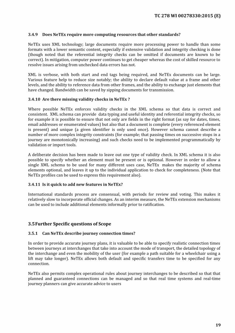
In order to provide accurate journey plans, it is valuable to be able to specify realistic connection timesbetween journeys at interchanges that take into account the mode of transport, the detailed topology ofthe interchange and even the mobility of the user (for example a path suitable for a wheelchair using alift may take longer). NeTEx allows both default and specific transfers time to be specified for anyconnection.
NeTEx also permits complex operational rules about journey interchanges to be described so that thatplanned and guaranteed connections can be managed and so that real time systems and real-timejourney planners can give accurate advice to users
19
TC 278 WI 00278330:2015 (E)
3.5.2 Does NeTEx support accessibility?
Yes, NeTEx supports the specification of accessibility attributes on both the fixed infrastructure (drawnfrom the CEN IFOPT standard) and on vehicle types used for specific journeys, so that full accessibilityaware journey planning can be provided, including micro-navigation through interchanges. Bothaccessibility properties and equipment for different disabilities (e.g. wheelchair spaces, navigability,tactile strips etc) and accessibility services (e.g. boarding assistance) can be defined. FurthermoreNeTEx defines a set of user needs (e.g. wheelchair, blindness, push chairs, etc ) that a journey planningengine can use to set criteria to find the optimal journey for a given set of accessibility criteria.
3.5.3 Can NeTEx handle frequency based services?
Frequency based services are typically specified as operating at a given interval, rather than particulartimes. From a passenger point of view multiple journeys will typically be presented as a single journeyrunning at an approximate interval, for example “every six to 10 minutes”. NeTEx uses TEMPLATEVEHICLE journeys to describe such journeys. From an operational point of view there will still need tobe specific service journeys scheduled to fulfil the required frequency of service and NeTEx can alsoinclude these to support real time journeys.
3.5.4 Can I have different journey timings for different times of day?
Part 2 of NeTEx includes reusable components for constructing timetables of journeys from reusablecomponents, NeTEx separates the concerns of where the timing of a PT route takes place (The TIMINGPATTERN made up of TIMING POINTs and TIMING LINKs) from the actual timing values (which areheld separately as RUN TIMEs and WAIT TIMEs). Different sets of timing values belong to differentTIME DEMAND TYPEs (Peak, off peak, late night etc) can be used with the same TIMING PATTERN togenerate accurate timetables for journeys at different times of day.
3.5.5 Can NeTEx describe zone based fares?
NeTEx can be used to describe zone based fare systems of any topology ranging from a simple patchwork (adjacent zones) to the complex, (honeycomb, doughnut) etc). The TARIFF ZONE allowszones to be associated with stops and stations. Mixed zonal and stage systems are also possible. Farepricing may be a flat fare system per zone, or zone to zone using a (DISTANCE MATRIX ELEMENT), orbe differentially priced for particular sequences of zones (using FRAE STRUCTURE ELMENTs inSEQUENCE).
3.5.6 Can I restrict certain products to certain classes of user?
Among the many different usage conditions that can be specified for NeTEx fare products arerestrictions on the type of user – child, senior, student, disabled, etc using a USER PROFILE that may begiven precise eligibility criteria (e.g. on age, membership, domicile, etc). A GROUP PROFILE allows thenumber and makeup of groups to be specified; it can also be used to specify companion criteria fordisabled users and other special cases.
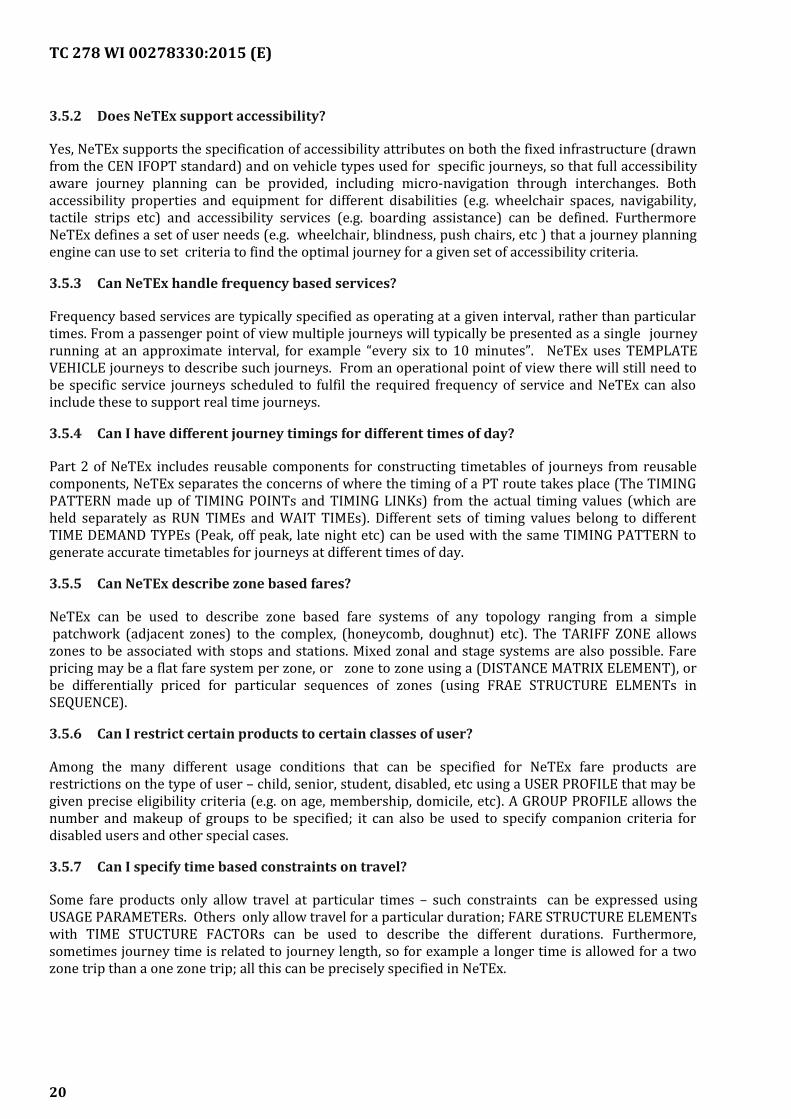
3.5.7 Can I specify time based constraints on travel?
Some fare products only allow travel at particular times – such constraints can be expressed usingUSAGE PARAMETERs. Others only allow travel for a particular duration; FARE STRUCTURE ELEMENTswith TIME STUCTURE FACTORs can be used to describe the different durations. Furthermore,sometimes journey time is related to journey length, so for example a longer time is allowed for a twozone trip than a one zone trip; all this can be precisely specified in NeTEx.
20
TC 278 WI 00278330:2015 (E)
Temporal conditions may also apply to the purchase or refund of tickets, likewise expressed as USAGEPARAMETERs attached to fare products.
As well as the routine examples given above, NeTEx can also handle more complex cases. For example,in the periphery of a large city, off peak times may start at different times in each station since by thetime a journey to the centre starting from the station ends, the peak period will have ended.
3.5.8 Can I integrate data from different countries with NeTEx?
Yes, one of the strengths of NeTEx is that it takes a global view of data identification, allowing dataelements from different name spaces to be exchanged in the same schema.
3.5.9 Does NeTEx support dynamic/ yield managed pricing?
For long distance travel, especially on-rail, there is increasing used of yield managed fares with dynamicpricing, provided by web services. Note that such applications increase rather than decrease the needfor standards such as NeTEx as such applications nonetheless require a machine readable definition ofthe access rights fare structure and usage conditions that apply to the products for which prices aresupplied. Furthermore the search parameters used to find the best fare for a user (such as age,possession of rail cards, fulfilment method etc) need to correspond to the properties of the fare product.The NeTEx Part3 specification and UML model includes an annex showing a sample fare query whichshows all the NeTEx model elements relevant for constructing a Fare API.
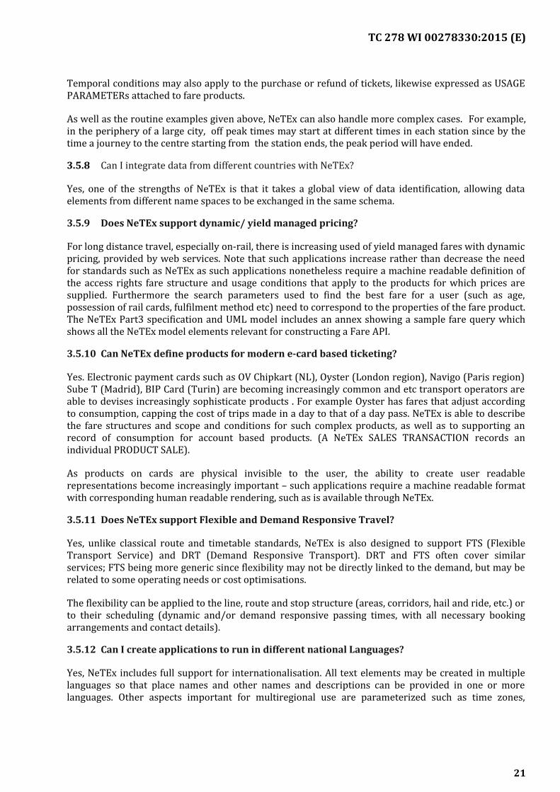
3.5.10 Can NeTEx define products for modern e-card based ticketing?
Yes. Electronic payment cards such as OV Chipkart (NL), Oyster (London region), Navigo (Paris region)Sube T (Madrid), BIP Card (Turin) are becoming increasingly common and etc transport operators areable to devises increasingly sophisticate products . For example Oyster has fares that adjust accordingto consumption, capping the cost of trips made in a day to that of a day pass. NeTEx is able to describethe fare structures and scope and conditions for such complex products, as well as to supporting anrecord of consumption for account based products. (A NeTEx SALES TRANSACTION records anindividual PRODUCT SALE).
As products on cards are physical invisible to the user, the ability to create user readablerepresentations become increasingly important – such applications require a machine readable formatwith corresponding human readable rendering, such as is available through NeTEx.
3.5.11 Does NeTEx support Flexible and Demand Responsive Travel?
Yes, unlike classical route and timetable standards, NeTEx is also designed to support FTS (FlexibleTransport Service) and DRT (Demand Responsive Transport). DRT and FTS often cover similarservices; FTS being more generic since flexibility may not be directly linked to the demand, but may berelated to some operating needs or cost optimisations.
The flexibility can be applied to the line, route and stop structure (areas, corridors, hail and ride, etc.) orto their scheduling (dynamic and/or demand responsive passing times, with all necessary bookingarrangements and contact details).
3.5.12 Can I create applications to run in different national Languages?
Yes, NeTEx includes full support for internationalisation. All text elements may be created in multiplelanguages so that place names and other names and descriptions can be provided in one or morelanguages. Other aspects important for multiregional use are parameterized such as time zones,
21
TC 278 WI 00278330:2015 (E)
currency, etc and the Calendar functions allow conditions based on different national holidays to bedescribed.
3.5.13 Can I have different version of data for the same element extant at the same time?
Yes, every NeTEx data element can be versioned, and multiple versions can coexist. Coherent sets ofdata are assembled for exchange using a ‘version frame’, which itself has a version and knows theversion of the elements in it. There are specific types of version frame for different type of data that arcommonly exchanged together (SERVICE, TIMETABLE, FARE etc).
3.5.14 Can I create Network maps with NeTEx?
Yes, one of the additional capabilities of NeTEx is the ability to define and exchange the full topology ofa network as presented in simplified view to a user (often with presentational attributes such as colour), with non-directional network segments, loops etc, while also retaining a projection onto the actualunderlying stops and route. This allows automatic creation of interactive map applications.
— The LINE element names the line and sets basic properties.
— The LINE NETWORK and LINE SECTION elements can be used to described the topology
— The ROUTE, ROUTELINK, and ROUTE POINT elements can be used to define the directionalelements of the underlying line
— The SCHEDULED STOP POINT can be used to define the stops of a line
All these objects can have their own geographic positions and geometry or an be projected onto acustom drawn map using a SCHEMATIC MAP element.
3.5.15 I have my own classification for Stops/ Lines / etc. Can NeTEx handle this?
Ye.s NeTEx allow arbitrary user defined code classifications for elements using the has TYPE OF STOP,TYPE OF LINE and other ‘Type of Entity’ elements that . In addition NeTEx, to encourage standardiseduse, also provides fixed enumerations of many commonly found classifications of specific elements,including types of equipment, on-board facilities, etc.. The ‘Key Value’ extension mechanism allows Alsoallows additional user defined attributes to be added, which can include classifiers.
3.6Comparison with other standards
3.6.1 How does NeTEx relate to Transmodel?
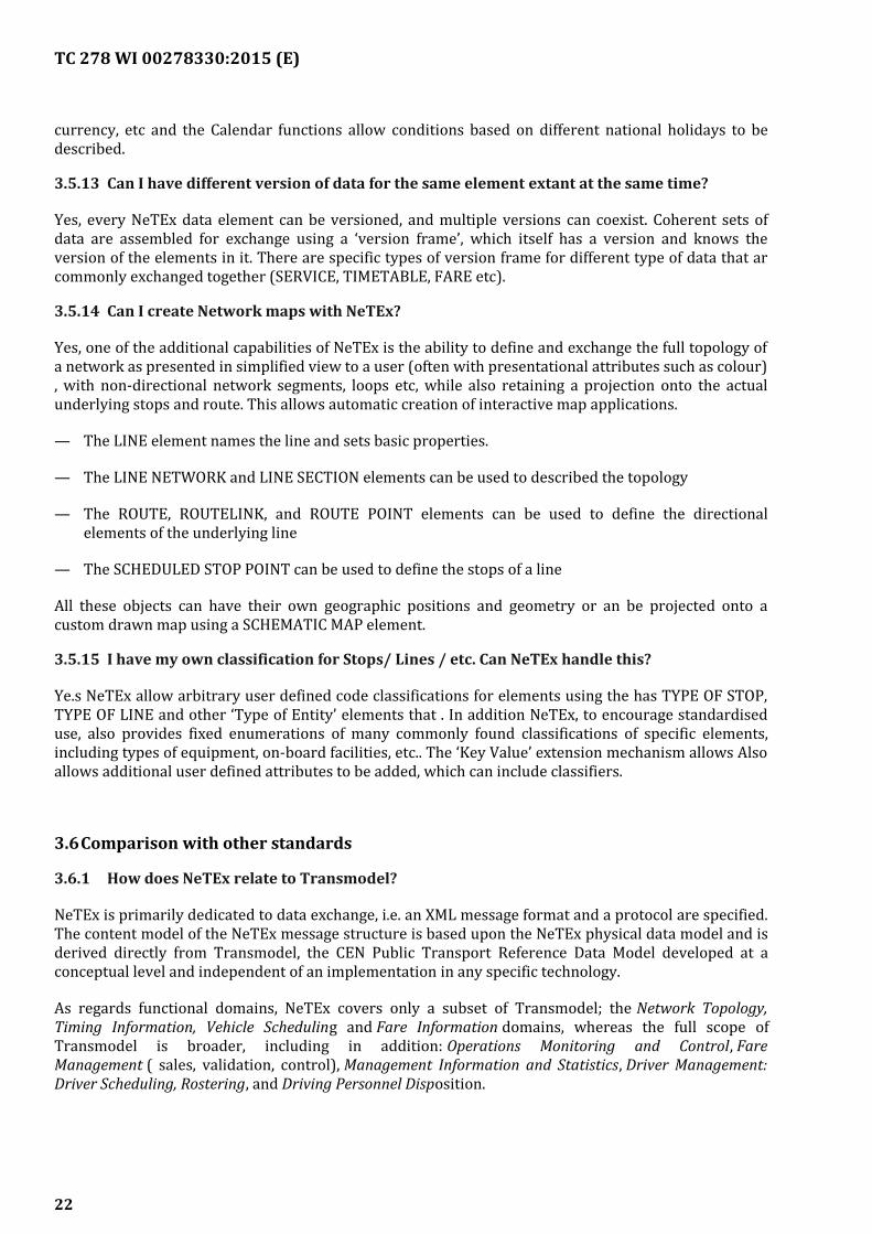
NeTEx is primarily dedicated to data exchange, i.e. an XML message format and a protocol are specified.The content model of the NeTEx message structure is based upon the NeTEx physical data model and isderived directly from Transmodel, the CEN Public Transport Reference Data Model developed at aconceptual level and independent of an implementation in any specific technology.
As regards functional domains, NeTEx covers only a subset of Transmodel; the Network Topology,Timing Information, Vehicle Scheduling and Fare Information domains, whereas the full scope ofTransmodel is broader, including in addition: Operations Monitoring and Control, FareManagement ( sales, validation, control), Management Information and Statistics, Driver Management:Driver Scheduling, Rostering, and Driving Personnel Disposition.
22
TC 278 WI 00278330:2015 (E)
The Transmodel conceptual model is broken down into modular packages with a mostly lineardependency graph between modules. The same organisation of packages is used in the Phsyical modeland XML schema so that there is a direct correspondence between the modules for each functionaldomain. This makes it straightforward to relate the high level design to the implementation.
3.6.2 How does NeTEx relate to IFOPT?
IFOPT, similarly to Transmodel specifies a data model, whereas the primary aim of NeTEx is to definedata exchange format. IFOPT has been integrated into the latest version of Transmodel (v6) and thus(see above) builds the basis for the NeTEx physical submodel dedicated to Fixed Objects for PublicTransport. This data domain is concerned with particular different types of sites (and theircomponents), such as points of interest, parking or stops and related objects like equipment, forinstance, but also pedestrian navigation paths and takes into account accessibility characteristics.NeTEx specifies the exchange of the data defined by the IFOPT model.
3.6.3 How does NeTEx compare with VDV?
Since NeTEx was influenced by existing European national standards and reference exchange protocolsit also ensures compatibility with VDV452 (“VDV Standard Interface Network / Timetable” referenceexchange protocol in Germany) at the level of conceptual and physical model. The aim of the VDV452 isto transfer network definitions and timetables from a source system into a target system, i.e. thetimetable data from a scheduling program is transferred to consumer systems for the purpose of transitoperations. NeTEx’s physical model provides specific elements (i.e. ExternalStopPointRef,ExternalJourneyRef, ExternalInterchangeRef, etc.) for VDV compatibility, specifically for use in AVMSsystems.A comparison between NeTEx and VDV452 is available at: www.vdv.de/netex.
3.6.4 How does NeTEx compare with TransXChange?
TransXChange, the UK national timetable standard, together with NaPTAN, the UK stop data standard,provides a functional equivalent subset of to the NeTEx stop and timetable elements in NeTEx Part1 &NeTEx Part2 and it is straightforward to map these to the contents of a NeTEx timetable frame. Bothstandards are based on Transmodel and allow the exchange of structural information such as timinginformation and journey patterns, The NeTEx representation is in many respects simpler, but is lessspecific about which elements must be present, and what the restrictions of values are. NeTEx alsoincludes many additional elements in Part 1 & Part 2 that are not in TransXChange, including supportcomplex for rail journeys, interchanges rules, . schematic maps, etc. TransXChange does not supportfares and nearly all of NeTEx Part 3 is outside of its scope. The result of 2004 FareXChange study of UKBus Fares was a significant input into NeTEx.
TransXChange also includes a small number of additional registration elements to support theElectronic Bus Service Registration process of the UK Vehicle Licensing authority (VOSA). Some of theregistration concepts (such as administrative areas) have equivalents in NeTEx, but a few of them arespecific to the UK regulatory context and are not supported by NeTEx. It would be possible to add aseparate UK extension to NeTEx to include these.
3.6.5 How does NeTEx compare with NEPTUNE?
NEPTUNE is a French standard for data exchange in the domain of Network Topology and Timetables. Itis based upon a draft EN version of Transmodel and incorporates several features of IFOPT as regardsstop typology, equipment and accessibility characteristics. It is comparable as regards the functionalcoverage to NeTEx-Part 1&2, but smaller regards to number of data covered.
23
TC 278 WI 00278330:2015 (E)
3.6.6 How does NeTEx compare with NOPTIS?
The Transmodel based Nordic Public Transport Interface Standard (NOPTIS) provides a consistent setof XML-exchange protocols covering both planned and real time aspects. One of these exchangeprotocols is the Data Input Interface (NOPTIS DII). This exchange protocol is optimised to transferversion-managed information concerning Network, Timetable, Vehicle Schedule, Services and otherdata to a PTA integrator system and is used extensively in Sweden and Denmark. NOPTIS DII was asignificant input to NeTEx. There exists a mapping between NeTEx and NOPTIS DII covering theCalendar, Timetable and Vehicle Schedule aspects showing how to use NeTEx in a way that supportsparallel partial data deliveries as in NOPTIS.
3.6.7 How does NeTEx compare with IFM?
Interoperable fare management (IFM) encompasses all systems and processes designed to manage thedistribution and use of fare products in an interoperable public transport environment. Such systemsare called interoperable when they enable the customer to use a portable electronic medium (e.g. acontact/contactless smart card) with compatible equipment (e.g. at stops, with retail systems, atplatform entry points or on board vehicles).
IFM-Part 1 is an ISO standard (ISO 14014-1) aiming at the definition a reference functional architecturefor Interoperable Fare Management System(s) and to identify
the requirements that are relevant to ensure Interoperability between several Actors in the context ofthe use of electronic tickets. The exchanges between IFM actors are described from the functional pointof view by the IFM standard, without the specification of data exchange format.
NeTEx- Part 3 describes fare elements as specified in public transport fare systems (zonal fares, flatfares, progressive fares, distance matrix, etc) and the resulting fare products using a conceptual datamodel, specifies a detailed physical data model for fares and derives data exchange message formats forfare exchange. The exchanges are concerning the information on fares (abstraction being made fromany particular medium), on the conditions of use of fare products, on associated fare productdistribution channels. Parameters necessary for the price calculation of fare products are also provided.
IFM is a process description and NeTEx is a data exchange format.
3.6.8 How does NeTEx compare with BISON ?
The official start of BISON, the platform for Beheer Informatie Standaarden Openbaar Vervoer Nederland(Management Information Standards Public Transport Netherlands), took place on 16 September 2008.The BISON platform is the result of an earlier decision on the part of the National Mobility Deliberations(NMB) to set up a management organisation for the further development of collective standards and theincorporation of these standards, insofar as possible, in existing concessions.
The main function of the BISON platform is to formulate, manage, harmonise and monitor all of theinformation standards that facilitate the exchange of information within the public transport sector.
BISON considers NeTEx to be the standard of choice for the future. Parts of the standard have beenapplied and used within BISON (e.g. Part 3 – Fares). In due time BISON will migrate from its national PTinformation exchange standard to NeTEx, and in due time NL specific BISON profile(s) will bedeveloped which will help to exchange travel information with other countries such as Germany annBelgium.
24
TC 278 WI 00278330:2015 (E)
3.6.9 How does NeTEx compare with the Taap/TSI standards?
There are three different TAP /TSI standards for fares; m – B1 (standard fares) B2 (IntegratedReservation fares) and b3 (special fares), each using different models (with some common elementsbetween B1 and B3) rand quite dffeent epresentations of the classes of user conditions, NeTEx is able torepresent the elements and attributes of all three models with a single uniform model, based on accessrights, using in particular DISTANCE MATRIX ELEMENTs to describe the point to point fares and USAGEPARAMATERs to describe the different conditions applying to the the rail products. Only a smallnumber of .FARE PRODUCTS are needed to describe the standard rail products. A number of salesconditions also relate to rail products and can be describe using SALES PACKAGES with NeTExDISTRIBUTION CHANNELs and FULFILMENT elements. The mapping of most elements isstraightforward and it is straightforward to create transformations using simple mapping tools such asthose found in the XML SPY product suite.
The TapTSI standars make used of a number of UIC code sets (all represented in NetEx as either sets ofenumerated values or ‘Types of value’ or in the case of station and oboard facilities as various types ofFacility or Equipment. . Stations (Locations in UIC terminology) can be uniformly represented in NeTExas Scheduled Stop points.
For details on the Tap/TSi model see the UML model of the mapping and the mapping specifications.
3.6.10 How does NeTEx compare with GTFS?
Google General Transport Feed Specification (GTFS) is a widely used format for distributing timetablesto third parties. The NeTEx and GTFS formats should be considered as complementary, coveringdifferent stages in the data management process: NeTEx is “upstream”, GTFS is “downstream”. NeTExdiffers from GTFS in that it has a much wider scope, and that it is intended for use in back office usecases under which data is generated, refined and integrated (requiring the exchange of additionalelements used to construct the timetable) , rather than just for provisioning journey planning systems(the prime purpose of GTFS).
GTFS covers stops, lines, and timetabled journey information (Gtf trips) sufficient to answer basicjourney planning queries. It supports only a few simple types of fare product . GTFS data identifiers arespecific to each data set and require registration of an identifier with Google.
NeTEx covers many other aspects of Public Transport Information apart from timetables (e.g. networkdescriptions, fare products,), as well as supporting a richer timetable model for export includingjourney patterns, timing patterns, joined journeys, train makeup, connection timings, etc. . This makes itable to exchange the data sets used to build tinetables as well as the resulting timetables themselves.NeTEx includes the additional information needed to provision real-time systems (such as destinationdisplays) and to link to operational systems (such as blocks) It also includes versioning and validitycondition mechanisms to support the repeated peer-to peer integration of many data from manydifferent parties.
Because it uses XML, NeTEx is able to package a complete data set as a single coherent document thatcan be managed and validated.
GTFS uses a traditional flat file format; this is compact and efficient but requires multiple files todescribe the different types of element and thus additional rules for naming and packaging the files as azip. Custom written tools are need to interpret and process the data.
It is possible to generate a full GTFS data set from NeTEx but not vice versa. The NeTEx UML includes aGTFS mapping package which shows how each GTFS element may be populated from the correspondingNeTEx element.
25
TC 278 WI 00278330:2015 (E)
4 NeTEx covered areas description
NeTEx covers different areas that fall into two main groups: General areas and Specific functional areas.
4.1General areas
— NeTEx Getting Started [Erreur : source de la référence non trouvée];
— NeTEx Design Methodology [];
— NeTEx Framework [Erreur : source de la référence non trouvée];
— NeTEx Reusable Components [Annex D];
4.2Specific functional areas
— NeTEx Networks [Erreur : source de la référence non trouvée];
— NeTEx Flexible Networks [Erreur : source de la référence non trouvée];
— NeTEx Accessibility [Erreur : source de la référence non trouvée];
— NeTEx Timetables [Erreur : source de la référence non trouvée];
— NeTEx Fares [Erreur : source de la référence non trouvée].
26
TC 278 WI 00278330:2015 (E)
Annex A(informative)
Getting Started
This Annex is intended to convey a high level view sufficient for a technical manager to appreciate someof the issues involved in implementing NeTEx, omitting many detailed considerations - for a detaileddescription please see the full CEN NeTEx specification, in particular Part 1 [N1] from which sections ofthis Annex are taken. Indication for getting started in the NeTEx protocol usage are reported.
A.1 Three common use cases
In practice, any new implementation of NeTEx is likely to be following one of three different use cases:
1) Adding support for export in NeTEx format from an existing PT data system that already hassimilar data content (but does not use the exact NeTEx model).
— In this case the implementer is constrained by her existing repository model, and the taskwill be to map the data into the equivalent NeTEx elements in the output documents. It is likelythat only certain elements and attributes will be populated, and the level of detail on theversioning of the exported will depend on what is supported in the originating system. Aglobally unique namespace or namespaces will need to be chosen for the identifiers and addedto the exported content.
— The NeTEx specification includes appendices with mappings into a number of EuropeanNational standards such as VDV452 (de) , NEPTUNE (fr) and BISON (nl) and also GTFS see [G1].
2) Adding support for import in NeTEx format into an existing PT data system that already hassimilar data content (but does not use the exact NeTEx model.
— The implementer is also constrained by the existing repository model, and the task will be tomap the data from the equivalent NeTEx elements into the internal format. It may be necessaryto extend the existing database model to handle additional elements or attributes present inNeTEx, especially if a lossless round trip exchange is envisaged (otherwise, additionalinformation provided by NeTEx but not required may just be ignored). The importing systemmay use NeTEx version data present in the document to identify differences in data sets. Theimport may be limited to the specific namespaces and identifier sets supported by the existingsystem.
3) Creating a new system based on parts of the Transmodel / NeTEx functional model, withimport and export capabilities for the NeTEx XML schema. The implementer will be free tochoose an internal repository model with a direct or straightforward mapping to the NeTExmodel as shown in the Physical UML mode. Only those features that will be in the functionalscope of the system need to be implemented – unsupported elements can be ignored.
In all three cases the implementer should be able to use automated tools to create an initial binding andNeTEx object model from the NeTEx XML schema (see below).
A.2 Basic Steps
This section sets out some basic considerations for using NeTEx.
27
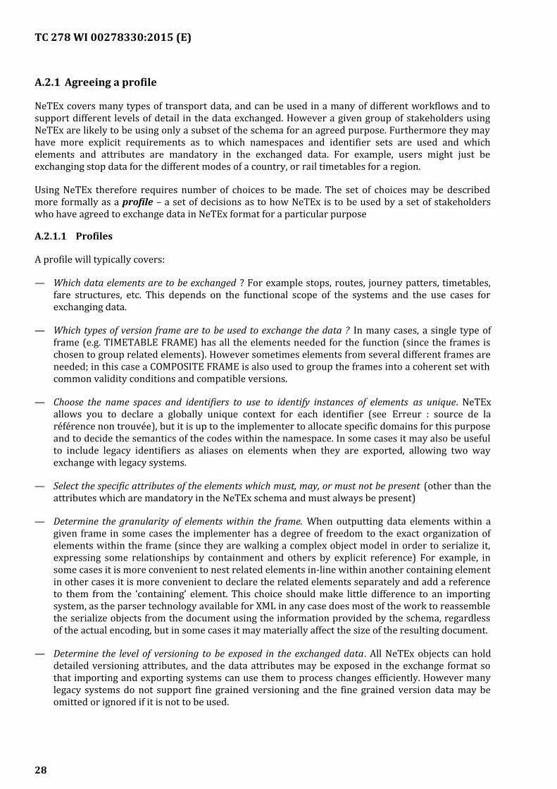
TC 278 WI 00278330:2015 (E)
A.2.1 Agreeing a profile
NeTEx covers many types of transport data, and can be used in a many of different workflows and tosupport different levels of detail in the data exchanged. However a given group of stakeholders usingNeTEx are likely to be using only a subset of the schema for an agreed purpose. Furthermore they mayhave more explicit requirements as to which namespaces and identifier sets are used and whichelements and attributes are mandatory in the exchanged data. For example, users might just beexchanging stop data for the different modes of a country, or rail timetables for a region.
Using NeTEx therefore requires number of choices to be made. The set of choices may be describedmore formally as a profile – a set of decisions as to how NeTEx is to be used by a set of stakeholderswho have agreed to exchange data in NeTEx format for a particular purpose
A.2.1.1 Profiles
A profile will typically covers:
— Which data elements are to be exchanged ? For example stops, routes, journey patters, timetables,fare structures, etc. This depends on the functional scope of the systems and the use cases forexchanging data.
— Which types of version frame are to be used to exchange the data ? In many cases, a single type offrame (e.g. TIMETABLE FRAME) has all the elements needed for the function (since the frames ischosen to group related elements). However sometimes elements from several different frames areneeded; in this case a COMPOSITE FRAME is also used to group the frames into a coherent set withcommon validity conditions and compatible versions.
— Choose the name spaces and identifiers to use to identify instances of elements as unique. NeTExallows you to declare a globally unique context for each identifier (see Erreur : source de laréférence non trouvée), but it is up to the implementer to allocate specific domains for this purposeand to decide the semantics of the codes within the namespace. In some cases it may also be usefulto include legacy identifiers as aliases on elements when they are exported, allowing two wayexchange with legacy systems.
— Select the specific attributes of the elements which must, may, or must not be present (other than theattributes which are mandatory in the NeTEx schema and must always be present)
— Determine the granularity of elements within the frame. When outputting data elements within agiven frame in some cases the implementer has a degree of freedom to the exact organization ofelements within the frame (since they are walking a complex object model in order to serialize it,expressing some relationships by containment and others by explicit reference) For example, insome cases it is more convenient to nest related elements in-line within another containing elementin other cases it is more convenient to declare the related elements separately and add a referenceto them from the ‘containing’ element. This choice should make little difference to an importingsystem, as the parser technology available for XML in any case does most of the work to reassemblethe serialize objects from the document using the information provided by the schema, regardlessof the actual encoding, but in some cases it may materially affect the size of the resulting document.
— Determine the level of versioning to be exposed in the exchanged data. All NeTEx objects can holddetailed versioning attributes, and the data attributes may be exposed in the exchange format sothat importing and exporting systems can use them to process changes efficiently. However manylegacy systems do not support fine grained versioning and the fine grained version data may beomitted or ignored if it is not to be used.
28
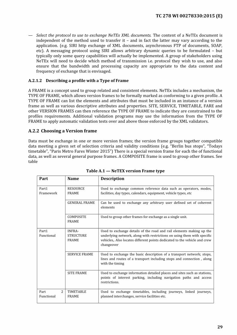
TC 278 WI 00278330:2015 (E)
— Select the protocol to use to exchange NeTEx XML documents. The content of a NeTEx document isindependent of the method used to transfer it – and in fact the latter may vary according to theapplication. (e.g. SIRI http exchange of XML documents, asynchronous FTP of documents, SOAP,etc). A messaging protocol using SIRI allows arbitrary dynamic queries to be formulated – buttypically only some query capabilities will actually be implemented. A group of stakeholders usingNeTEx will need to decide which method of transmission i.e. protocol they wish to use, and alsoensure that the bandwidth and processing capacity are appropriate to the data content andfrequency of exchange that is envisaged.
A.2.1.2 Describing a profile with a Type of Frame
A FRAME is a concept used to group related and consistent elements. NeTEx includes a mechanism, theTYPE OF FRAME, which allows version frames to be formally marked as conforming to a given profile. ATYPE OF FRAME can list the elements and attributes that must be included in an instance of a versionframe as well as various descriptive attributes and properties. SITE, SERVICE, TIMETABLE, FARE andother VERSION FRAMES can then reference the TYPE OF FRAME to indicate they are constrained to theprofiles requirements. Additional validation programs may use the information from the TYPE OFFRAME to apply automatic validation tests over and above those enforced by the XML validators.
A.2.2 Choosing a Version frame
Data must be exchange in one or more version frames; the version frame groups together compatibledata meeting a given set of selection criteria and validity conditions (e.g. “Berlin bus stops”, “Todaystimetable”, “Paris Metro Fares Winter 2015”) There is a special version frame for each the of functionaldata, as well as several general purpose frames. A COMPOSITE frame is used to group other frames. Seetable
Table A.1 — NeTEX version Frame type
Part Name Description
Part1Framework
RESOURCEFRAME
Used to exchange common reference data such as operators, modes,facilities, day types, calendars, equipment, vehicle types, etc
GENERAL FRAME Can be used to exchange any arbitrary user defined set of coherentelements
COMPOSITEFRAME
Used to group other frames for exchange as a single unit.
Part1Functional
INFRA-STRUCTUREFRAME
Used to exchange details of the road and rail elements making up theunderlying network, along with restrictions on using them with specificvehicles,. Also locates different points dedicated to the vehicle and crewchangeover
SERVICE FRAME Used to exchange the basic description of a transport network; stops,lines and routes of a transport including stops and connection , alongwith the timing
SITE FRAME Used to exchange information detailed places and sites such as stations,points of interest parking, including navigation paths and accessrestrictions.
Part 2Functional
TIMETABLEFRAME
Used to exchange timetables, including journeys, linked journeys,planned interchanges, service facilities etc.
29
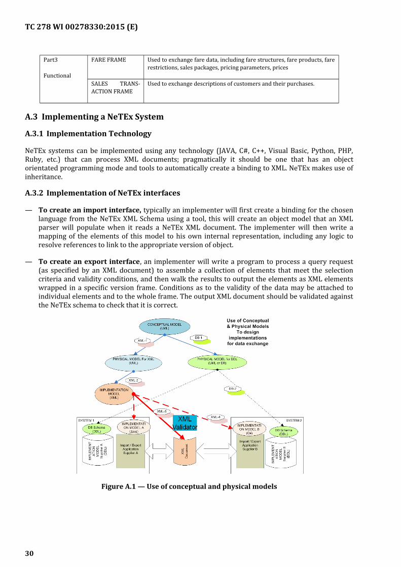
TC 278 WI 00278330:2015 (E)
Part3
Functional
FARE FRAME Used to exchange fare data, including fare structures, fare products, farerestrictions, sales packages, pricing parameters, prices
SALES TRANS-ACTION FRAME
Used to exchange descriptions of customers and their purchases.
A.3 Implementing a NeTEx System
A.3.1 Implementation Technology
NeTEx systems can be implemented using any technology (JAVA, C#, C++, Visual Basic, Python, PHP,Ruby, etc.) that can process XML documents; pragmatically it should be one that has an objectorientated programming mode and tools to automatically create a binding to XML. NeTEx makes use ofinheritance.
A.3.2 Implementation of NeTEx interfaces
— To create an import interface, typically an implementer will first create a binding for the chosenlanguage from the NeTEx XML Schema using a tool, this will create an object model that an XMLparser will populate when it reads a NeTEx XML document. The implementer will then write amapping of the elements of this model to his own internal representation, including any logic toresolve references to link to the appropriate version of object.
— To create an export interface, an implementer will write a program to process a query request(as specified by an XML document) to assemble a collection of elements that meet the selectioncriteria and validity conditions, and then walk the results to output the elements as XML elementswrapped in a specific version frame. Conditions as to the validity of the data may be attached toindividual elements and to the whole frame. The output XML document should be validated againstthe NeTEx schema to check that it is correct.
Figure A.1 — Use of conceptual and physical models
30
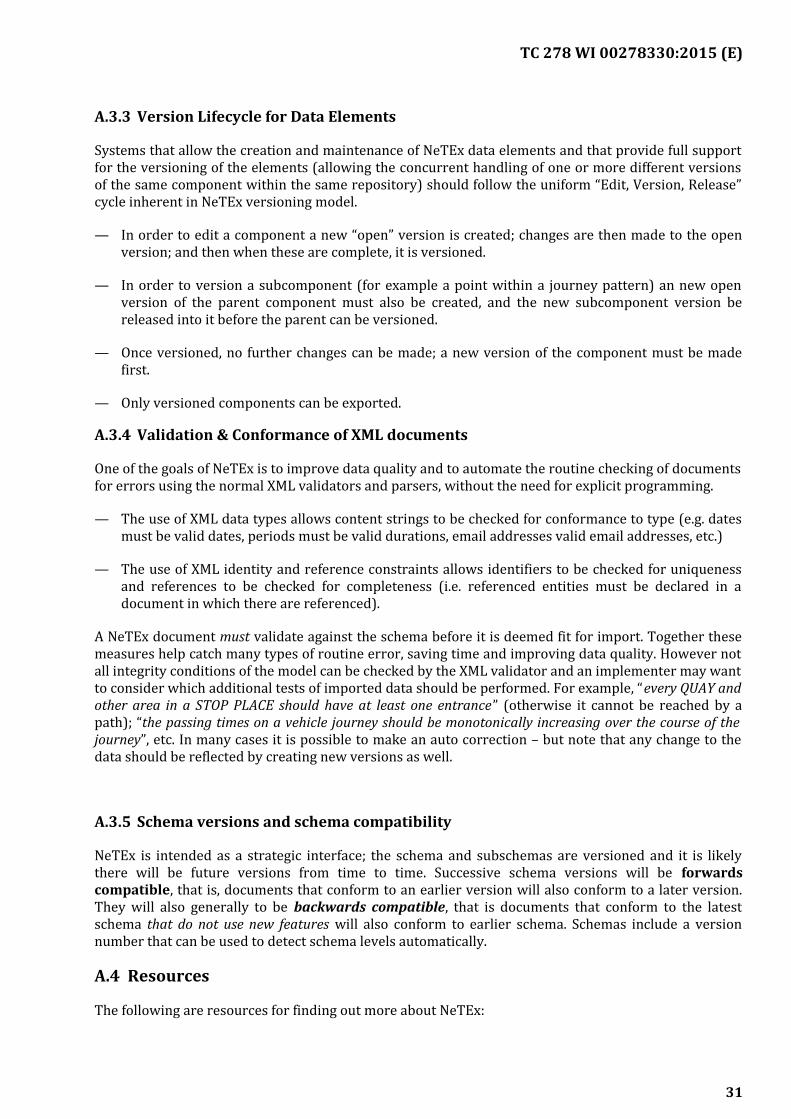
TC 278 WI 00278330:2015 (E)
A.3.3 Version Lifecycle for Data Elements
Systems that allow the creation and maintenance of NeTEx data elements and that provide full supportfor the versioning of the elements (allowing the concurrent handling of one or more different versionsof the same component within the same repository) should follow the uniform “Edit, Version, Release”cycle inherent in NeTEx versioning model.
— In order to edit a component a new “open” version is created; changes are then made to the openversion; and then when these are complete, it is versioned.
— In order to version a subcomponent (for example a point within a journey pattern) an new openversion of the parent component must also be created, and the new subcomponent version bereleased into it before the parent can be versioned.
— Once versioned, no further changes can be made; a new version of the component must be madefirst.
— Only versioned components can be exported.
A.3.4 Validation & Conformance of XML documents
One of the goals of NeTEx is to improve data quality and to automate the routine checking of documentsfor errors using the normal XML validators and parsers, without the need for explicit programming.
— The use of XML data types allows content strings to be checked for conformance to type (e.g. datesmust be valid dates, periods must be valid durations, email addresses valid email addresses, etc.)
— The use of XML identity and reference constraints allows identifiers to be checked for uniquenessand references to be checked for completeness (i.e. referenced entities must be declared in adocument in which there are referenced).
A NeTEx document must validate against the schema before it is deemed fit for import. Together thesemeasures help catch many types of routine error, saving time and improving data quality. However notall integrity conditions of the model can be checked by the XML validator and an implementer may wantto consider which additional tests of imported data should be performed. For example, “every QUAY andother area in a STOP PLACE should have at least one entrance” (otherwise it cannot be reached by apath); “the passing times on a vehicle journey should be monotonically increasing over the course of thejourney”, etc. In many cases it is possible to make an auto correction – but note that any change to thedata should be reflected by creating new versions as well.
A.3.5 Schema versions and schema compatibility
NeTEx is intended as a strategic interface; the schema and subschemas are versioned and it is likelythere will be future versions from time to time. Successive schema versions will be forwardscompatible, that is, documents that conform to an earlier version will also conform to a later version.They will also generally to be backwards compatible, that is documents that conform to the latestschema that do not use new features will also conform to earlier schema. Schemas include a versionnumber that can be used to detect schema levels automatically.
A.4 Resources
The following are resources for finding out more about NeTEx:
31
TC 278 WI 00278330:2015 (E)
A.5 NeTEx CEN Technical specifications,
NeTEx is formally described as set of PDF documents that may be purchased from CEN national bodiessuch as VDV, AFNOR, BSI, NEN,
— NeTEx Part1: Network description [N1];
— NeTEx Part2: Timing information [N2];
— NeTEx Part3: Fare description [N3].
The CEN Technical specifications are large and somewhat unwieldy documents prepared in accordancewith CEN rules.
A.6 NeTEx UML Models
NeTEx provides models in UML notation of all the NeTEx entities and relationships as electronicartefacts. The models are modularised and provide a convenient way of browsing and studying theNeTEx models. The UML physical model includes many additional diagrams and views that are notpresent in the CEN Specification that help to understand the model and its dependencies.
The NeTEx UML model includes two distinct models:
— NeTEx UML Conceptual Model;
— NeTEx UML Physical Model.
Ancillary models showing a mapping to TAP/TSI B1, B2 and B3 specifications and to GTFS are alsoavailable (see [N1], [N2]).
In order to view the UML models you need an appropriate tool, such as the Enterprise Architect viewer(www.sparxsystems.au) or an XMI enabled UML viewer.
The NeTEx models are free and are available from www.netex-cen.eu (from the Download page).
A.7 NeTEx XML Schema
The primary software resource from implementing a NeTEx interface is the NeTEx XML schema whichis available at the www.netex-cen.eu
Two main variants of the schema are available each providing a different protocol for embedding thesame content model subschemas.
b) Simple NeTEx documents exchange: (NeTEx _publication.xsd). A schema to use with NeTExdocuments input or output by a system that are exchanged as files using FTP, email etc.
c) NeTEx document exchange using SIRI http requests: (NeTEx_siri_SG.xsd). A schema that embedsthe NeTEx elements in a sequence of http messages that define request/response andpublish/subscribe interchanges for exchanging NeTEx data. Requests used NeTEx elements tospecify the desired data. Responses are wrapped in version frames. The messages arespecialisations of the SIRI framework.
32
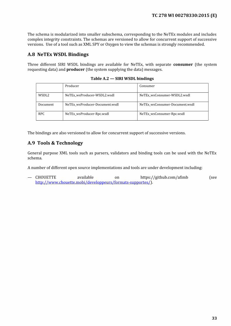
TC 278 WI 00278330:2015 (E)
The schema is modularized into smaller subschema, corresponding to the NeTEx modules and includescomplex integrity constraints. The schemas are versioned to allow for concurrent support of successiveversions. Use of a tool such as XML SPY or Oxygen to view the schemas is strongly recommended.
A.8 NeTEx WSDL Bindings
Three different SIRI WSDL bindings are available for NeTEx, with separate consumer (the systemrequesting data) and producer (the system supplying the data) messages.
Table A.2 — SIRI WSDL bindings
Producer Consumer
WSDL2 NeTEx_wsProducer-WSDL2.wsdl NeTEx_wsConsumer-WSDL2.wsdl
Document NeTEx_wsProducer-Document.wsdl NeTEx_wsConsumer-Document.wsdl
RPC NeTEx_wsProducer-Rpc.wsdl NeTEx_wsConsumer-Rpc.wsdl
The bindings are also versioned to allow for concurrent support of successive versions.
A.9 Tools & Technology
General purpose XML tools such as parsers, validators and binding tools can be used with the NeTExschema.
A number of different open source implementations and tools are under development including:
— CHOUETTE available on https://github.com/afimb (seehttp://www.chouette.mobi/developpeurs/formats-supportes/).
33
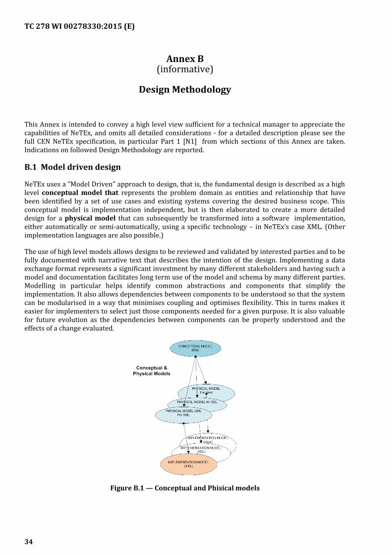
TC 278 WI 00278330:2015 (E)
Annex B(informative)
Design Methodology
This Annex is intended to convey a high level view sufficient for a technical manager to appreciate thecapabilities of NeTEx, and omits all detailed considerations - for a detailed description please see thefull CEN NeTEx specification, in particular Part 1 [N1] from which sections of this Annex are taken.Indications on followed Design Methodology are reported.
B.1 Model driven design
NeTEx uses a “Model Driven” approach to design, that is, the fundamental design is described as a highlevel conceptual model that represents the problem domain as entities and relationship that havebeen identified by a set of use cases and existing systems covering the desired business scope. Thisconceptual model is implementation independent, but is then elaborated to create a more detaileddesign for a physical model that can subsequently be transformed into a software implementation,either automatically or semi-automatically, using a specific technology – in NeTEx’s case XML. (Otherimplementation languages are also possible.)
The use of high level models allows designs to be reviewed and validated by interested parties and to befully documented with narrative text that describes the intention of the design. Implementing a dataexchange format represents a significant investment by many different stakeholders and having such amodel and documentation facilitates long term use of the model and schema by many different parties.Modelling in particular helps identify common abstractions and components that simplify theimplementation. It also allows dependencies between components to be understood so that the systemcan be modularised in a way that minimises coupling and optimises flexibility. This in turns makes iteasier for implementers to select just those components needed for a given purpose. It is also valuablefor future evolution as the dependencies between components can be properly understood and theeffects of a change evaluated.
Figure B.1 — Conceptual and Phisical models
34
TC 278 WI 00278330:2015 (E)
B.1.1 The Transmodel Conceptual model
The conceptual model used in NeTEx is based on Transmodel, the CEN Reference model for PublicTransport [T1], [T2] [T3], [T4], developed over the course of the past two decades from aharmonisation and systemisation of a number of proven European National standards. Transmodelfocuses on Transport concepts at a high level design level and as an object model. It does not need toaddress detailed implementation points such as the use of namespaces, or how elements should beorganised when serialised in a linear format such as XML.
NeTEx, as a concrete physical format which can be implemented, must make technology specificdecisions on such points and also adds in functional attributes for a number of elements based onexisting European transport systems
B.2 Consistent Terminology
One of the design goals of NeTEx is to uphold a consistent set of terminology for a given PublicTransport data concept wherever it is used. The names of public transport concepts in everydaylanguage are often fuzzy, the same word having different meanings in different contexts depending onwhether one is discussing the passenger, the vehicle or the timetable, or describing a process or anentity. For example, consider “Stop”, “Service”, “Route”, “Journey”, etc, each of which has multiplemeanings in English. This problem is compounded at a European level since different languages mayhave further differences in their semantic categories as well (that is to say a given term may cover asubtly different set of connotations in each specific language – as say with Reise/ Viaggio/ Voyage/Journey/ Potovanje/ Reis etc). Transmodel tries to follow a restricted, consistent terminology, using asingle term for a single concept each with its own well-defined description. Quite often this results in arather cumbersome technical vocabulary, for example a VEHICLE JOURNEY, SCHEDULED STOP POINT,ACCESS RIGHT ASSIGNMENT (Transmodel terms are given in uppercase by convention), andsometimes a term is used somewhat artificially to exclude some colloquial senses (for example inTransmodel TRIP is used only for passengers while JOURNEY is used only for vehicles), but theapproach has significant advantages in precision and, once understood and adopted, in reducing overallcomplexity. Readers should however to be aware of this convention in reading NeTEx documents.
B.3 UML Notation
NeTEx represents the underlying model using Unified Modelling Language (UML) class diagrams[U1], stored alongside an electronic representation of the model in a repository. UML is an industrystandard notation for describing complex software models and supports a number of different types ofrelationship between software components (associate, aggregation, inheritance etc). Two levels of UMLmodel are provided – A high level conceptual UML model which is implementation independent, and aphysical model which includes detailed attributes and details needed to support implementation asXML schema. Textual definitions are attached to the NeTEx schema elements as well.
Each model is carefully modularised into packages within the NeTEx Part1, Part2, and Part3 parts, witha given package having correspondences at each level. (UML dependency diagrams are provided todocument the relationship between modules).
In practice, the use of a UML model requires the use of modern design tool (such as EnterpriseArchitect) that offer powerful navigation and visualization capabilities to examine a model and itsdocumentation interactively in many different views. Such views may be included as illustrations in adocument such as this but represent only a static snapshot. For in depth study of NeTEx use of a tool isrecommended
35
TC 278 WI 00278330:2015 (E)
B.4 XML schema
NeTEx uses W3C XML schema to describe data. XML Schema Definition (XSD) is a general purposelanguage for describing data model elements in a form that can be serialized and transmitted betweendifferent computer system.
B.4.1 XML Benefits
XML allows for a semantically rich representation of data and has several important advantages over aflat file technology
— Validity checking: a schema allows not only the structure of the model to be described but alsomany integrity constraints. These can cover not only basic data types (dates, times, numbers,allowed values for enumerations, etc) but also complex referential integrity conditions that can beused to ensure that a coherent data set is delivered, such as unique identifiers and satisfied crossreferences. This automates much of the data quality checking process and assists problemresolution between different participants.
— Reuse mechanisms: XML is a modern Object Orientated Language and includes powerfulmechanism such as inheritance and embedded groups that simplify representations and improvethe maintainability of implementations.
— Programming language and Software Tool support: There is widespread support for XML inmany different tools and programming languages, making it relatively straightforward toimplement import and export procedures. In particular the complex task of parsing andreassembling data is largely done by the standard XML parsers without any further programmingeffort being required.
— Flexibility: Normally standards need to be able to evolve over time to support changes in thebusiness requirements. XML is a self-describing format that can include optional elements and it ispossible to have successive, but backwards compatible versions in concurrent use, distinguishableby different schema version attributes: This is valuable in a distributed implementation wherethere are many different systems using different versions of the system at the same time and thatwill choose to upgrade to new releases at different times.
B.4.2 XML Drawbacks
Use of XML schema technology also has some drawbacks.
— Document size: XML implementations are relatively verbose compared to flat file formats,requiring more bandwidth to transmit and greater computational resource to process. Inmitigation, the semantically richness may also be used to condense content to avoid unnecessaryrepetition (as is found say in TAP price data) and data can in any case be compressed fortransmission using normal zip techniques. Where size is critical additional optimisations can bemade. (“It is easier to make a correct model fast than a fast model correct”)
— Multiplicity of components: the use of discrete, functionally orthogonal, reusable components,implemented with the various inheritance mechanism of XML (subtyping, embedding of groups etc)so as to be highly modular, means that the specification is quite fragmented and has a large numberof small elements, making it harder to comprehend. This can be mitigated by the use of powerfulediting and visualisation tools (such as XML SPY or Oxygen) which are able to reassemble theelements into views for users to inspect and edit schemas.
36
TC 278 WI 00278330:2015 (E)
— Complexity of Interpretation: The semantic richness of NeTEx means that sometimes there ismore than one way of potentially encoding a concept. When the difference is purely syntactic thisdoes not matter in practice (for example, in-lining elements rather than declaring them separatelyand cross-referencing them), as the parser technology available for XML in any case does most ofthe work to reassemble the serialize objects from the document using the information provided bythe schema, regardless of the actual encoding. A more serious problem is that in certain cases theremay appear to be more than one plausible way of encoding data. Usually there will be a preferred“more correct” way, but deciding exactly the correct representation to use may involve expertconsideration of subtle aspects of the model. For example, does a temporal condition apply to awhole SALES PACKAGE or just to one particular parameter such the PURCHASE WINDOW? Orshould a condition be attached to a FARE PRODUCT or to a SALES PACKAGE based on the FAREPRODUCT? To mitigate this, users concerned to exchange a particular set of data (for example VDVtimetables or TAP /TSI fares) typically specify a “profile” that spells out the preferred choice ofelements, and examples (as cited in this document) are also valuable. A profile can be furtherdescribed by a TYPE OF FRAME which is can indicate as “metadata” which elements should orshould not be present.
— Limited constraints: Although XML schemas support many important types of integrity constraintto check data, certain more complicated constraints cannot be expressed and must be checkedprogrammatically in an incoming program. For example, for the sequence of stops making up thecalling pattern of a vehicle journey, it might be required that there is only a departure time at theorigin, only an arrival time at the destination; but at least one departure or arrival times for all theintermediate stops. NeTEx in fact makes most properties optional in the schema so that the sameschema can be used for many different applications, in effect not even using all of XML’s capabilitiesto express multiplicity of occurrence.
B.5 Tools & Technology
NeTEx’s technology choices (XML, UML) represent mainstream technologies with widespread tool andplatform support and a large pool of people with the necessary technology skills.
B.6 Modularisation of the framework
A large conceptual model and schema such as NeTEx (which has several hundred entities) needs to bemodularised into smaller submodels in order to be manageable; both to understand it; to implementand test systems based on it; and to allow the separate evolution of unrelated subdomains over time.NeTEx encapsulates model elements into small packages of just a few related elements concerned witha particular function, each with their own self-contained diagrams and documentation. The coreframework elements and common components are included in the base packages in Part1 and thenreferenced by the dependent packages that deliver the actual concrete functional of NeTEx.
Dependencies are linearized as far as possible, so that base packages can be used independently ofother packages. To help users navigate the models the documentation includes both high level and lowlevel dependency diagrams, and also uses a consistent set of colours for components from differentfunctional
37
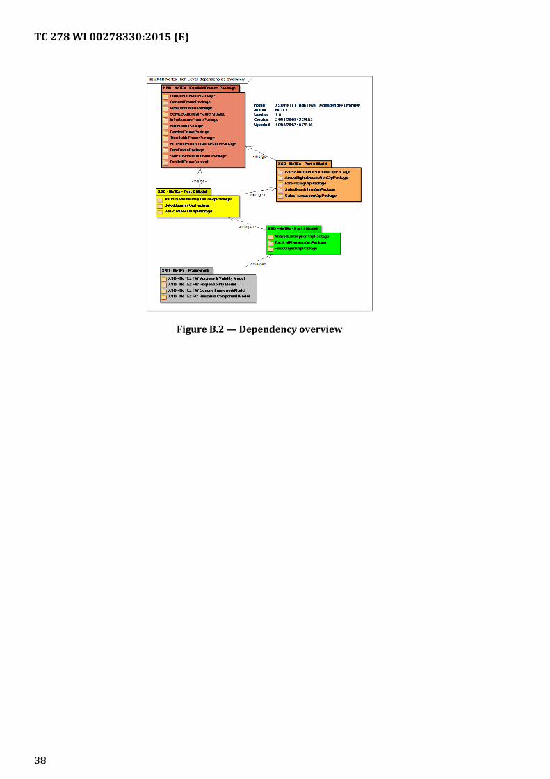
TC 278 WI 00278330:2015 (E)
Figure B.2 — Dependency overview
38
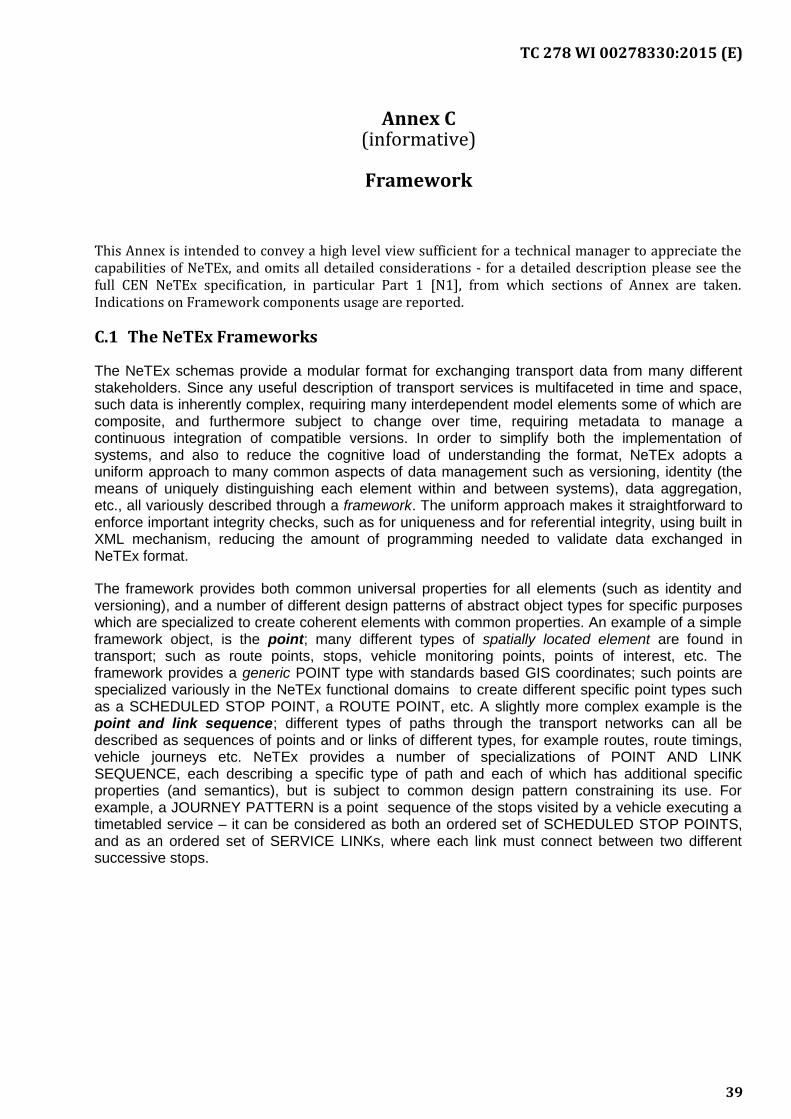
TC 278 WI 00278330:2015 (E)
Annex C(informative)
Framework
This Annex is intended to convey a high level view sufficient for a technical manager to appreciate thecapabilities of NeTEx, and omits all detailed considerations - for a detailed description please see thefull CEN NeTEx specification, in particular Part 1 [N1], from which sections of Annex are taken.Indications on Framework components usage are reported.
C.1 The NeTEx Frameworks
The NeTEx schemas provide a modular format for exchanging transport data from many differentstakeholders. Since any useful description of transport services is multifaceted in time and space,such data is inherently complex, requiring many interdependent model elements some of which arecomposite, and furthermore subject to change over time, requiring metadata to manage acontinuous integration of compatible versions. In order to simplify both the implementation ofsystems, and also to reduce the cognitive load of understanding the format, NeTEx adopts auniform approach to many common aspects of data management such as versioning, identity (themeans of uniquely distinguishing each element within and between systems), data aggregation,etc., all variously described through a framework. The uniform approach makes it straightforward toenforce important integrity checks, such as for uniqueness and for referential integrity, using built inXML mechanism, reducing the amount of programming needed to validate data exchanged inNeTEx format.
The framework provides both common universal properties for all elements (such as identity andversioning), and a number of different design patterns of abstract object types for specific purposeswhich are specialized to create coherent elements with common properties. An example of a simpleframework object, is the point; many different types of spatially located element are found intransport; such as route points, stops, vehicle monitoring points, points of interest, etc. Theframework provides a generic POINT type with standards based GIS coordinates; such points arespecialized variously in the NeTEx functional domains to create different specific point types suchas a SCHEDULED STOP POINT, a ROUTE POINT, etc. A slightly more complex example is thepoint and link sequence; different types of paths through the transport networks can all bedescribed as sequences of points and or links of different types, for example routes, route timings,vehicle journeys etc. NeTEx provides a number of specializations of POINT AND LINKSEQUENCE, each describing a specific type of path and each of which has additional specificproperties (and semantics), but is subject to common design pattern constraining its use. Forexample, a JOURNEY PATTERN is a point sequence of the stops visited by a vehicle executing atimetabled service – it can be considered as both an ordered set of SCHEDULED STOP POINTS,and as an ordered set of SERVICE LINKs, where each link must connect between two differentsuccessive stops.
39
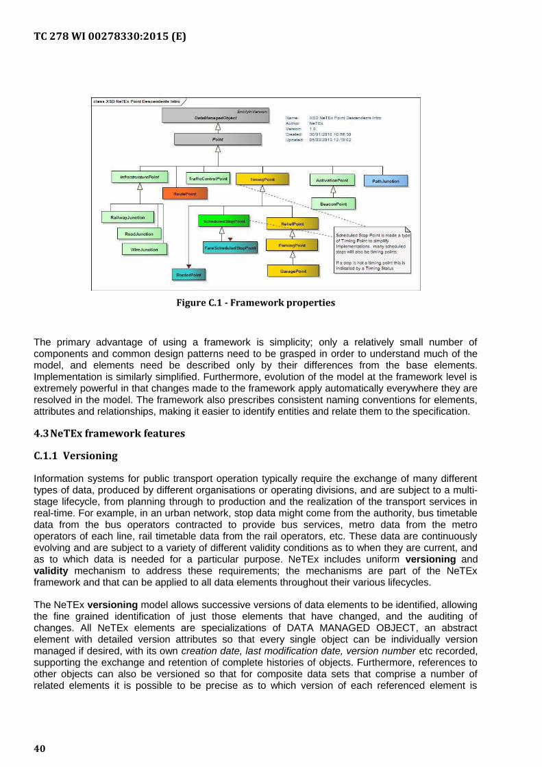
TC 278 WI 00278330:2015 (E)
Figure C.1 - Framework properties
The primary advantage of using a framework is simplicity; only a relatively small number ofcomponents and common design patterns need to be grasped in order to understand much of themodel, and elements need be described only by their differences from the base elements.Implementation is similarly simplified. Furthermore, evolution of the model at the framework level isextremely powerful in that changes made to the framework apply automatically everywhere they areresolved in the model. The framework also prescribes consistent naming conventions for elements,attributes and relationships, making it easier to identify entities and relate them to the specification.
4.3NeTEx framework features
C.1.1 Versioning
Information systems for public transport operation typically require the exchange of many differenttypes of data, produced by different organisations or operating divisions, and are subject to a multi-stage lifecycle, from planning through to production and the realization of the transport services inreal-time. For example, in an urban network, stop data might come from the authority, bus timetabledata from the bus operators contracted to provide bus services, metro data from the metrooperators of each line, rail timetable data from the rail operators, etc. These data are continuouslyevolving and are subject to a variety of different validity conditions as to when they are current, andas to which data is needed for a particular purpose. NeTEx includes uniform versioning andvalidity mechanism to address these requirements; the mechanisms are part of the NeTExframework and that can be applied to all data elements throughout their various lifecycles.
The NeTEx versioning model allows successive versions of data elements to be identified, allowingthe fine grained identification of just those elements that have changed, and the auditing ofchanges. All NeTEx elements are specializations of DATA MANAGED OBJECT, an abstractelement with detailed version attributes so that every single object can be individually versionmanaged if desired, with its own creation date, last modification date, version number etc recorded,supporting the exchange and retention of complete histories of objects. Furthermore, references toother objects can also be versioned so that for composite data sets that comprise a number ofrelated elements it is possible to be precise as to which version of each referenced element is
40
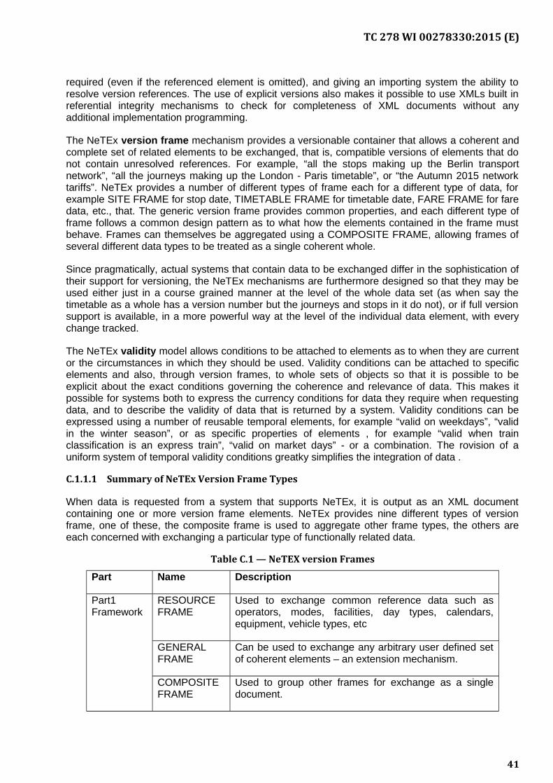
TC 278 WI 00278330:2015 (E)
required (even if the referenced element is omitted), and giving an importing system the ability toresolve version references. The use of explicit versions also makes it possible to use XMLs built inreferential integrity mechanisms to check for completeness of XML documents without anyadditional implementation programming.
The NeTEx version frame mechanism provides a versionable container that allows a coherent andcomplete set of related elements to be exchanged, that is, compatible versions of elements that donot contain unresolved references. For example, “all the stops making up the Berlin transportnetwork”, “all the journeys making up the London - Paris timetable”, or “the Autumn 2015 networktariffs”. NeTEx provides a number of different types of frame each for a different type of data, forexample SITE FRAME for stop date, TIMETABLE FRAME for timetable date, FARE FRAME for faredata, etc., that. The generic version frame provides common properties, and each different type offrame follows a common design pattern as to what how the elements contained in the frame mustbehave. Frames can themselves be aggregated using a COMPOSITE FRAME, allowing frames ofseveral different data types to be treated as a single coherent whole.
Since pragmatically, actual systems that contain data to be exchanged differ in the sophistication oftheir support for versioning, the NeTEx mechanisms are furthermore designed so that they may beused either just in a course grained manner at the level of the whole data set (as when say thetimetable as a whole has a version number but the journeys and stops in it do not), or if full versionsupport is available, in a more powerful way at the level of the individual data element, with everychange tracked.
The NeTEx validity model allows conditions to be attached to elements as to when they are currentor the circumstances in which they should be used. Validity conditions can be attached to specificelements and also, through version frames, to whole sets of objects so that it is possible to beexplicit about the exact conditions governing the coherence and relevance of data. This makes itpossible for systems both to express the currency conditions for data they require when requestingdata, and to describe the validity of data that is returned by a system. Validity conditions can beexpressed using a number of reusable temporal elements, for example “valid on weekdays”, “validin the winter season”, or as specific properties of elements , for example “valid when trainclassification is an express train”, “valid on market days” - or a combination. The rovision of auniform system of temporal validity conditions greatky simplifies the integration of data .
C.1.1.1 Summary of NeTEx Version Frame Types
When data is requested from a system that supports NeTEx, it is output as an XML documentcontaining one or more version frame elements. NeTEx provides nine different types of versionframe, one of these, the composite frame is used to aggregate other frame types, the others areeach concerned with exchanging a particular type of functionally related data.
Table C.1 — NeTEX version Frames
Part Name Description
Part1Framework
RESOURCEFRAME
Used to exchange common reference data such asoperators, modes, facilities, day types, calendars,equipment, vehicle types, etc
GENERALFRAME
Can be used to exchange any arbitrary user defined setof coherent elements – an extension mechanism.
COMPOSITEFRAME
Used to group other frames for exchange as a singledocument.
41

TC 278 WI 00278330:2015 (E)
Part1Functional
INFRA-STRUCTUREFRAME
Used to exchange details of the road and rail elementsmaking up the underlying network, along with restrictionson using them with specific vehicles. Also locatesdifferent points dedicated to the vehicle and crewchangeover
SERVICEFRAME
Used to exchange the basic description of a transportnetwork; stops, lines and routes of a transport includingstops and connection , along with the timing.
SITE FRAME Used to exchange information detailed places and sitessuch as stations, points of interest parking, includingnavigation paths and access restrictions.
Part 2Functional
TIMETABLEFRAME
Used to exchange timetables, including journeys,journey parts and couplings, planned interchanges,service facilities, etc.
Part3
Functional
FARE FRAME Used to exchange fare data, including fare structures,fare products, fare restrictions, sales packages, pricingparameters, prices
SALESTRANS-ACTIONFRAME
Used to exchange descriptions of customers and theirpurchases.
C.1.2 Identifiers, uniqueness of reference and Namespaces
The task of gathering, collating and aggregating data for a public transport network necessarilymust be distributed among many different organisations, especially when creating data sets forlarge cities, regions, or whole countries. Computer systems require unique identifiers to distinguisheach individual data element as it appears serialised in an exchange format. The data sets coveredby NeTEx are large and belong to many different stakeholders, each of whom may have their ownsystem of identifying elements.
In order to be able to integrate data repeatedly from many diverse systems, it must be possible togive each object a globally unique persistent identifier regardless of its data source. NeTEx isdesigned to support large scale data integration, and supports uniqueness though the use ofnamespaces, based on domain and path strings (as familiarly seen in urls), a readily available andwell established existing global standard to provide domain names which may be used as theprefixes of labels. Thus for example, a UK bus stop might be identified within the NaPTAN domain,as “naptan.org.uk:21407867”, or a German rail timetable as “farhplan.db.de:1234” (or perhaps“db.de/fahrplan:1234”. Every NeTEx element in a document is given a unique identifier and NeTExXML schema enforces well defined uniqueness constraints. To avoid verbose repetition,namespaces can be declared at a version frame level and overridden on individual elements only asnecessary.
Identifiers are unique within each type of NeTEx object. Thus for example, the TIMING POINT withid of ”hde:123“ is different from the ROUTE POINT with an id of ”hde:123”, since they are differentclasses of element. Multiple identifier aliases, for example to support mappings to legacy system
42
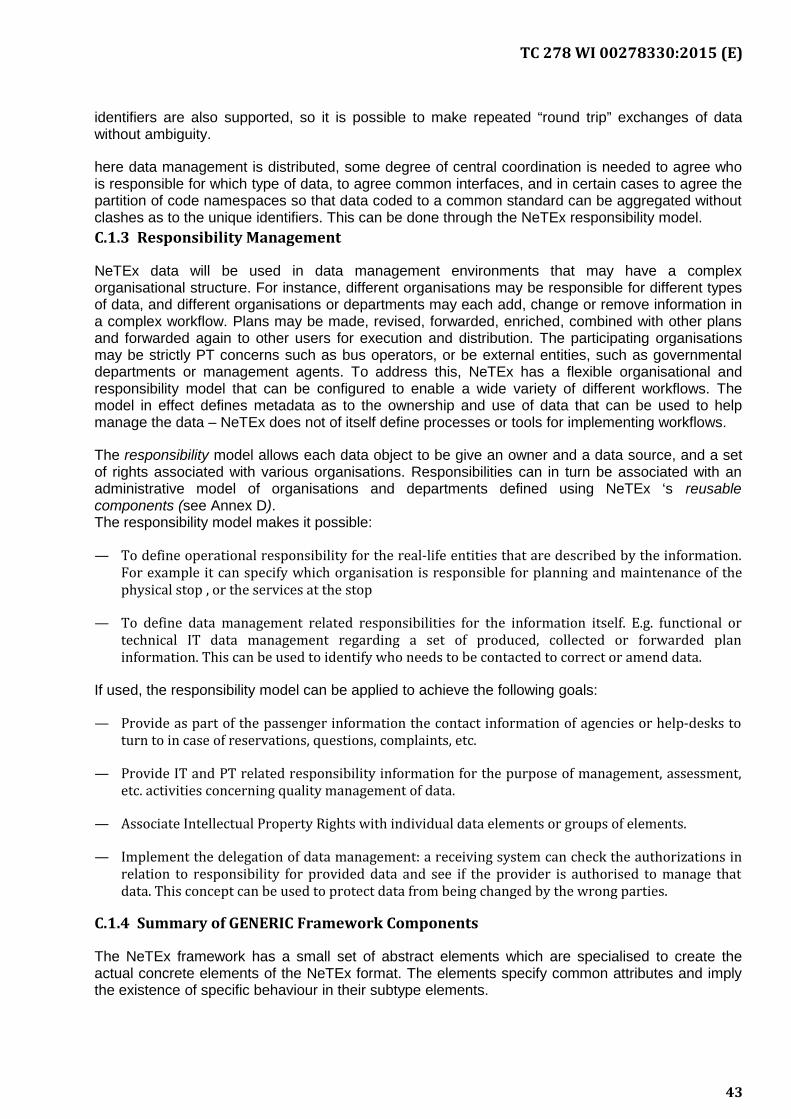
TC 278 WI 00278330:2015 (E)
identifiers are also supported, so it is possible to make repeated “round trip” exchanges of datawithout ambiguity.
here data management is distributed, some degree of central coordination is needed to agree whois responsible for which type of data, to agree common interfaces, and in certain cases to agree thepartition of code namespaces so that data coded to a common standard can be aggregated withoutclashes as to the unique identifiers. This can be done through the NeTEx responsibility model.C.1.3 Responsibility Management
NeTEx data will be used in data management environments that may have a complexorganisational structure. For instance, different organisations may be responsible for different typesof data, and different organisations or departments may each add, change or remove information ina complex workflow. Plans may be made, revised, forwarded, enriched, combined with other plansand forwarded again to other users for execution and distribution. The participating organisationsmay be strictly PT concerns such as bus operators, or be external entities, such as governmentaldepartments or management agents. To address this, NeTEx has a flexible organisational andresponsibility model that can be configured to enable a wide variety of different workflows. Themodel in effect defines metadata as to the ownership and use of data that can be used to helpmanage the data – NeTEx does not of itself define processes or tools for implementing workflows.
The responsibility model allows each data object to be give an owner and a data source, and a setof rights associated with various organisations. Responsibilities can in turn be associated with anadministrative model of organisations and departments defined using NeTEx ‘s reusablecomponents (see Annex D). The responsibility model makes it possible:
— To define operational responsibility for the real-life entities that are described by the information.For example it can specify which organisation is responsible for planning and maintenance of thephysical stop , or the services at the stop
— To define data management related responsibilities for the information itself. E.g. functional ortechnical IT data management regarding a set of produced, collected or forwarded planinformation. This can be used to identify who needs to be contacted to correct or amend data.
If used, the responsibility model can be applied to achieve the following goals:
— Provide as part of the passenger information the contact information of agencies or help-desks toturn to in case of reservations, questions, complaints, etc.
— Provide IT and PT related responsibility information for the purpose of management, assessment,etc. activities concerning quality management of data.
— Associate Intellectual Property Rights with individual data elements or groups of elements.
— Implement the delegation of data management: a receiving system can check the authorizations inrelation to responsibility for provided data and see if the provider is authorised to manage thatdata. This concept can be used to protect data from being changed by the wrong parties.
C.1.4 Summary of GENERIC Framework Components
The NeTEx framework has a small set of abstract elements which are specialised to create theactual concrete elements of the NeTEx format. The elements specify common attributes and implythe existence of specific behaviour in their subtype elements.
43
TC 278 WI 00278330:2015 (E)
C.1.4.1 Generic Framework elements
The following provide basic abstract elements for NeTEx function:
— DATA MANAGED OBJECT element: Provides common version management and responsibilityproperties. It is the ur object for all NeTEx elements.
— VERSION FRAME element: Provides a properties and behaviour of a version frame, a container forholding other elements for exchange. It is specialised as a number of different concrete frames aslisted in Table 1 above.
C.1.4.2 Design pattern Framework components
The following abstract elements can be specialised to create elements with particular desiredproperties that will interact in specific roles with other elements :
— GROUP OF ENTITies element: Provides abstract properties for elements that reference a set ofother entities, (for example a ZONE includes a set of POINT references) a means of groupingelements and is used as abstract supertype for many different aggregates.
— The POINT & LINK model provides abstract elements for defining 0D points and 1D links.
— The LINK SEQUENCE model provides elements to defining graphs of points or links as commonlyfound in layered PT models.
— The ZONE model provides a model for defining 2D zones (with possible 0D point centroid).
— The PROJECTION model provides a means of defining mappings between different graphs ofPOINTs and LINKs, so that for example a transport route (a schematic view of a vehicle path) maybe mapped to a road infrastructure element.
— The PLACE element provides a model for defining named places and links between them, includingtheir relationship to COUNTRies. It can have spatial and navigation properties.
— The ASSIGNMENT element provides common behaviour for dependent ancillary elements whichassign additional and often alternative sets of attributes to other entities.
— TYPE OF VALUE is used where the choice of values of attributes is restricted to a discrete “code set”of named values but the set itself needs to be extensible; this is specialised to create specific sets ofvalues whose use can be validated using the XML validator. A VALUE SET is used to group valuedefinitions.
44
TC 278 WI 00278330:2015 (E)
Annex D(informative)
Reusable Components
Annex is intended to convey a high level view sufficient for a technical manager to appreciate thecapabilities of NeTEx, and omits all detailed considerations - for a detailed description please see thefull CEN NeTEx specification, from which sections of Annex are taken. Indications on ReusableComponents usage are reported.
D.1 The NeTEx Reusable Components
As well as achieving reusability by specialising abstract framework components (see Erreur : sourcede la référence non trouvée), NeTEx also provides a number of reusable components to representcommon concepts found in various transport data functional models; these may be used as objectswithout further specialisation.
The elements are used throughout NeTEx Part1 (see [N1]), Part2 (see [N2]) and Part3 (see [N3]);for example transport OPERATORs, transport MODEs, DAY TYPEs, OPERATING DAY, etc.Standardized versions of these common objects are provided, which include a wide range ofattributes to support the different functions of NeTEx (and drawn from proven European nationalstandards). NeTEx sub-schemas reuse these existing components rather than introducing separateelements in each different application context. Also, in line with normative CEN standardisationprinciples, NeTEx references existing underlying standards where appropriate, such as GML for GIScoordinates, or ISO country codes to identify countries.
When included in a NeTEx document, instances of the reusable components will be grouped with aversion frame (see “NeTEx Frameworks - White paper” ); the RESOURCE FRAME in particular isused to exchange general-purpose components such as ORGANISATIONs and FACILITIEs.Frames of different types may be grouped within a COMPOSITE FRAME.
D.2 Summary of Reusable Components
— The NeTEx reusable components can be grouped under several headings:
— Framework Components: ready-made components that support framework levelfunctions, such as VERSION.
— General functional components: ready-made components of generic applicability, suchas NOTICEs.
— Transport functional components: ready-made components that can be used directly,such as OPERATORs., AVAILABILITY CONDITIONs, FACILITIES, etc
D.2.1 Reusable Component types
The NeTEx framework provides a set of ready made reusable elements that can be used withoutfurther specialisation. Some of these are ancillary metadata elements to support frameworkbehaviour (for example for automatic comparison of versions):
45
TC 278 WI 00278330:2015 (E)
— VERSION: Versions are reified as explicit elements which can be given descriptions and otherproperties and be used in conditions.
— VALIDITY CONDITION. Conditions are specified in terms of temporal or other values and can beassociated with version frames and other elements to indicate when they apply. An AVAILABILITYCONDITION is specialisation of VALIDITY CONDITION that uses a number of predefined elementsto specify a temporal condition, for example as a day of the week or occurrence of a holiday.
— DATA SOURCE: Sources indicate the origin system from which a data came.
— RESPONSIBILITY SET: Each NeTEx element can be associated with a Responsibility Set whichindicates the owner and other rights and responsibilities. These can be used both to supportproblem resolution processes and to track IPR rights.
D.2.2 General Reusable Component types
A second group of ready-made components defines useful functional elements that are not specificto transport applications.
— NOTICE Model – Defines footnotes and other NOTICEs that can be associated with elements.
— REUSABLE AVAILABILITY Model – Defines standardised temporal VALIDITY CONDITIONs such asday types for specifying when an event or condition is valid, i.e. in effect.
— TOPOGRAPHIC Model – Defines named TOPOGRAPHIC PLACES that provide a context for SITES,STATIONS, STOPS etc. that may be served by public transport, with an ISO based Country definition.
D.2.3 Transport Reusable Component types
The organisational reusable components describe the basic operator mode and topography contextfor the various transport data elements.
— TRANSPORT MODE Model – Defines standard Transport modes & submodes.
— TRANSPORT ORGANISATION Model – Defines OPERATORS, AUTHORITIES and other TransportORGANISATIONs.
— OTHER ORGANISATION Model – Defines SERVICED ORGANISATIONs and other non-operatorORGANISATIONs.
The equipment reusable components describe the generic equipment properties, and classificationsof servers and facilities that can be associated with services and sites.
— GENERIC EQUIPMENT Model – Defines general EQUIPMENT properties for EQUIPMENT elementsthat can be associated with VEHICLES and SITEs. EQUIPMENT can be specialised to create specifictypes of equipment, for example WAITING ROOM EQUIPMENT, STAIR EQUIPMENT, WHEELCHAIREQUIPMENT etc with complex attributes
— FACILITY Model – Defines simple named service and facility categories that can be associated withstops, timetables and other NeTEx elements. Facilities have a name and code but no attributes.
— CLASSES OF USE (First class, second class, etc), ticket types etc. define classifiers.
The vehicle related components define types of vehicles and vehicle equipment.
46
TC 278 WI 00278330:2015 (E)
— VEHICLE TYPE Model – Defines VEHICLE TYPES, VEHICLE MODELs and VEHICLEs.
— TRAIN model, defines train composition (COMPOUND TRAIN) and the facilities of the carriages(VEHICLE EQUIPMENT PROFILE).
— VEHICLE EQUIPMENT Model – Defines specific VEHICLE EQUIPMENT Types and actualEQUIPMENT usage on a VEHICLE TYPES, VEHICLE MODELS and VEHCILES.
— SERVICE REQUIREMENTS Model – Defines requirements for VEHICLE TYPEs to go on specificservices.
Finally the following miscellaneous element provides a general purpose mechanism for creating“smart” maps that link to NeTEx model elements
— SCHEMATIC MAP Model – Defines general purpose SCHEMATIC MAP contents that can be used tolink data elements to visualisations such as network maps and interactive displays.
D.3 Summary of Reusable Data types
NeTEx uses a small set of XML data types to specify the attributes of the different NeTEx elements,facilitating validation and type checking of data in implementations. Where possible these are basedon existing XML, CEN or W3C standards.
— XML built in data types are used to set specific types for data elements wherever possible,allowing the efficient validation of NeTEx documents by normal XML validators to detect typeand grammar (Schema) errors. Examples are, date, time, number, boolean, duration, etc.Timestamps are generally given in 24 hour format with a time zone suffix to avoid ambiguity.Periods (e.g. 20 days 3 months 1 year, etc.) are defined using the XML duration type.
— NeTEx text elements are designed to support international use; the language of all descriptivestrings can be specified through the MultilingualString type and alternative translations indifferent languages can be associated with key text names. Language defaults can be set at theframe level when exchanging sets of data in a given language.
— To specify spatial coordinates NeTEx uses a core subset of the GML schema, allowing adifferent alternative well-defined systems of spatial coordinates to be used, including WGS84 asa widely used default.
— Common quantitative unit dimensions such as height, distance and weight are specifically typedusing added XML types that can be validated. SI units are generally used by default.
— Common reusable base types such as an email format, time zone, etc., are provided to assistXML validation, and a LOCALE mechanism is provided to set a time zone and other localityspecific properties.
— Enumerated types are used to restrict the set of allowed values for data elements that take afixed set of values, again allowing validation by the XML parser. Where an open ended set ofvalues is needed a TYPE OF VALUE is used (see NeTEx Framework – White Paper).
47
TC 278 WI 00278330:2015 (E)
Annex E(informative)
Representing Public Transport Networks in NeTEx
This Annex is intended to convey a high level view sufficient for a technical manager to appreciate thecapabilities of the CEN standard NeTEx, and omits all detailed considerations that can be found in thedetailed documentation. NeTEx documentation is divided into three parts [N1], [N2], [N3]; in particularNetwork representation is covered in Part1 [N1] and is mainly concerned with describing fixedNetworks (stops, routes, lines etc).
E.1 NeTEx Methodology
NeTEx uses a “model driven design”, i.e. the development starts from a conceptual model, fromwhich a physical UML model and an XML implementation is derived.
The European Public Transport Reference Data Model, known as Transmodel, is the conceptualbasis for the development (see [T1], [T2], [T3]).
E.2 Scope
The NeTEx public transport network representation can be used for networks for any mode oftransport, including rail, bus, metro, ferry, etc. The same model elements can be used in differentways in different views, for example ranging from a high level schematic view of the network forpassengers, to a stop by stop sequence of a route for a specific scheduled journey.
Both the different types of locations (stations, airports bus stops etc), their layout and theirproperties such as accessibility (see Erreur : source de la référence non trouvée) and facilities (seeErreur : source de la référence non trouvée) can be described. The relationship between therepresentation of a stop as a set of physical points (e.g. a station and its platforms); the stop as apoint in a timetable (which may be independent of platform) and the stop as point for real-themeasurement and display can all be described precisely, so that a common network representationcan be reused from both planning and operational purposes.
NeTEx includes representations of rail stations and rail routes designed to be compatible withTAP/TSI and other requirements so that the network model is adequate for representing longdistance rail networks. Concepts such as platforms and boarding positions on platforms (and theirrelation to train makeup) can be covered so that full information for rail passengers can be given.
Basic infrastructure elements, such as road/railway/wire elements are also described together withthe constraints on the tactical planning of operations imposed by infrastructure characteristics, e.g.choice of an adequate vehicle type (described in [N1] and [N2]).
Some of the fixed network elements may be used to describe the structure of flexible networks, forFlexible Transport Systems or Demand Responsive Systems (see Erreur : source de la référencenon trouvée).
48
TC 278 WI 00278330:2015 (E)
E.3 Corresponding NeTEx documentation
A detailed specification of NeTEx capabilities as regards the representation of public transportnetworks can be found in two distinct sub sections of Part1 [N1]:
Section 1 - Framework, describes concepts and models shared by all NeTEx functional parts andincludes three different aspects, namely:
— Common framework mechanisms: such as versioning, validity, grouping, and responsibilitymetadata, allowing the automated tracking, and processing of successive versions. VERSIONFRAME, VERSION, VALIDITY CONDITION (see [2]),
— Generic Patterns: defining abstract components that can be specialised to create concrete elementsin the various NeTEx functional domains, in particular the POINT, LINK and SEQUENCE of LINKcomponents used to define network layers,
— Reusable components: certain common components, for example TRANSPORT MODES,CALENDARS, DAY TYPEs, EQUIPMENT etc. that are not specific to any particular functional part ofNeTEx but are widely used in several different functional areas (see also [3]).
Section 2 – Public Transport Network Topology, describes the concrete objects for the spatialdescription of Public Transport networks. As well as their own specific semantics, these objectstypically have geometric features giving them common spatial properties. Many of such objects areused for the tactical planning of operations and in the context of passenger information.
The network topology is represented either through simple or complex object classes like:
— Paths through the network: ROUTEs, JOURNEY PATTERNs, TIMING PATTERNs, SERVICEPATTERNs, etc. which are linear features, linked to point features such as
— Operational points: TIMING POINTs, GARAGEs, CREW POINTs, BEACON POINTs, etc
— Passenger service points: SCHEDULED STOP POINTs, STOP AREAs, CONNECTIONs, etc.
The Network Model includes representations of the physical locations to which passengers maytravel using elements from the Fixed Objects for Public Transport mode [T4]l.
— STOP PLACEs, PARKING, PASSENGER NAVIGATION PATHs, ENTRANCEs,
— POINTs OF INTEREST, PARKING PLACEs,
— ACCESSIBILITY features (see [5]).
E.4 Approach
E.4.1 Reconciling different views of the network
Public Transport network data may originate from many different departments or sub-systems of anorganisation or organisations. When data from different sources (for instance, departments) are puttogether, inconsistencies may be found in the distances in space used, or in the timings to cross thespaces. An example is the calculation of the distance run by a vehicle: an operation managementsystem may be concerned with the number of kilometres covered by a bus during a time period (e.g.at a particular hour of a particular type of day) along the “itineraries”, while an accounting systemmay be concerned with the number of kilometres as agreed in contractual obligations and computed
49
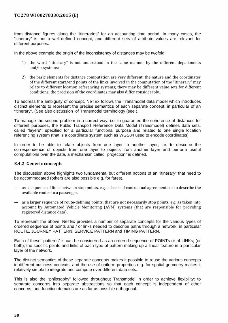
TC 278 WI 00278330:2015 (E)
from distance figures along the “itineraries” for an accounting time period. In many cases, the“itinerary” is not a well-defined concept, and different sets of attribute values are relevant fordifferent purposes.
In the above example the origin of the inconsistency of distances may be twofold:
1) the word “itinerary” is not understood in the same manner by the different departmentsand/or systems;
2) the basic elements for distance computation are very different: the nature and the coordinatesof the different start/end points of the links involved in the computation of the “itinerary” mayrelate to different location referencing systems; there may be different value sets for differentconditions; the precision of the coordinates may also differ considerably..
To address the ambiguity of concept, NeTEx follows the Transmodel data model which introducesdistinct elements to represent the precise semantics of each separate concept, in particular of an“itinerary”. (See also discussion of Transmodel terminology (see ).
To manage the second problem in a correct way, i.e. to guarantee the coherence of distances fordifferent purposes, the Public Transport Reference Data Model (Transmodel) defines data sets,called “layers”, specified for a particular functional purpose and related to one single locationreferencing system (that is a coordinate system such as WGS84 used to encode coordinates).
In order to be able to relate objects from one layer to another layer, i.e. to describe thecorrespondence of objects from one layer to objects from another layer and perform usefulcomputations over the data, a mechanism called “projection” is defined.
E.4.2 Generic concepts
The discussion above highlights two fundamental but different notions of an “itinerary” that need tobe accommodated (others are also possible e.g. for fares),
— as a sequence of links between stop points, e.g. as basis of contractual agreements or to describe theavailable routes to a passenger.
— as a larger sequence of route-defining points, that are not necessarily stop points, e.g. as taken intoaccount by Automated Vehicle Monitoring (AVM) systems (that are responsible for providingregistered distance data),
To represent the above, NeTEx provides a number of separate concepts for the various types ofordered sequence of points and / or links needed to describe paths through a network; in particularROUTE, JOURNEY PATTERN, SERVICE PATTERN and TIMING PATTERN.
Each of these “patterns” is can be considered as an ordered sequence of POINTs or of LINKs; (orboth); the specific points and links of each type of pattern making up a linear feature in a particularlayer of the network.
The distinct semantics of these separate concepts makes it possible to reuse the various conceptsin different business contexts, and the use of uniform properties e.g. for spatial geometry makes itrelatively simple to integrate and compute over different data sets..
This is also the “philosophy” followed throughout Transmodel in order to achieve flexibility: toseparate concerns into separate abstractions so that each concept is independent of otherconcerns, and function domains are as far as possible orthogonal.
50
TC 278 WI 00278330:2015 (E)
Figure E.1 - Generic Concept Approach
E.5 Basic spatial network aspects
E.5.1 Routes and work patterns
The main linear patterns used to define the spatial structure of a Public Transport Network are:ROUTE, JOURNEY PATTERN, TIMING PATTERN and SERVICE PATTERN.
— A ROUTE is an ordered list of located ROUTE POINTs defining one single path through the road (orrail) network. A ROUTE may pass through the same ROUTE POINT more than once. ROUTE LINKsmay be used to specify attributes of a link.
— The ROUTE network does not necessarily correspond strictly to the infrastructure network,represented in the figure below as the “street network” (made up of ROAD ELEMENTs), and astypically defined in a GIS model. However, an obvious correspondence between the ROUTE andROAD ELEMENT sequences exists: this correspondence describes the exact shape of the ROUTE.
— A JOURNEY PATTERN is defined as an ordered list of SCHEDULED STOP POINTs (i.e. points wherepassengers can board or alight from vehicles) and TIMING POINTs (i.e. points against which thetiming information necessary to build schedules may be recorded) on a single ROUTE, describingthe pattern of working for public transport vehicles. A JOURNEY PATTERN may pass through thesame point more than once. Again links (SERVICE LINKS, TIMING LINKS etc) can be used to providea link based representation if needed.
— The sequence of TIMING POINTs of a JOURNEY PATTERN determines a TIMING PATTERN (green inthe figure below) and the sequence of SCHEDULED STOP POINTs (of a JOURNEY PATTERN)determines a SERVICE PATTERN (red in the figure below).
51
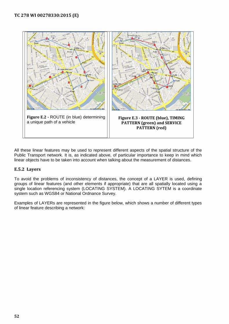
TC 278 WI 00278330:2015 (E)
Figure E.2 - ROUTE (in blue) determininga unique path of a vehicle
Figure E.3 - ROUTE (blue), TIMINGPATTERN (green) and SERVICE
PATTERN (red)
All these linear features may be used to represent different aspects of the spatial structure of thePublic Transport network. It is, as indicated above, of particular importance to keep in mind whichlinear objects have to be taken into account when talking about the measurement of distances.
E.5.2 Layers
To avoid the problems of inconsistency of distances, the concept of a LAYER is used, defininggroups of linear features (and other elements if appropriate) that are all spatially located using asingle location referencing system (LOCATING SYSTEM). A LOCATING SYTEM is a coordinatesystem such as WGS84 or National Ordnance Survey.
Examples of LAYERs are represented in the figure below, which shows a number of different typesof linear feature describing a network:
52
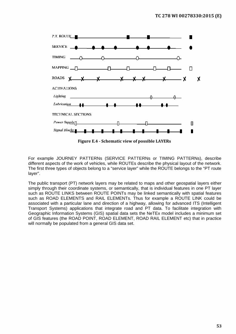
TC 278 WI 00278330:2015 (E)
Figure E.4 - Schematic view of possible LAYERs
For example JOURNEY PATTERNs (SERVICE PATTERNs or TIMING PATTERNs), describedifferent aspects of the work of vehicles, while ROUTEs describe the physical layout of the network.The first three types of objects belong to a “service layer” while the ROUTE belongs to the “PT routelayer”.
The public transport (PT) network layers may be related to maps and other geospatial layers eithersimply through their coordinate systems, or semantically, that is individual features in one PT layersuch as ROUTE LINKS between ROUTE POINTs may be linked semantically with spatial featuressuch as ROAD ELEMENTS and RAIL ELEMENTs. Thus for example a ROUTE LINK could beassociated with a particular lane and direction of a highway, allowing for advanced ITS (IntelligentTransport Systems) applications that integrate road and PT data. To facilitate integration withGeographic Information Systems (GIS) spatial data sets the NeTEx model includes a minimum setof GIS features (the ROAD POINT, ROAD ELEMENT, ROAD RAIL ELEMENT etc) that in practicewill normally be populated from a general GIS data set.
53
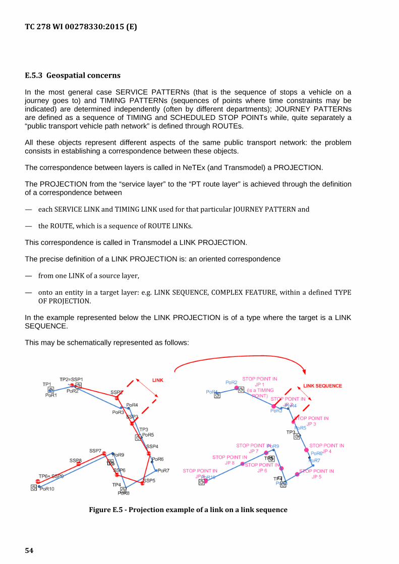
TC 278 WI 00278330:2015 (E)
E.5.3 Geospatial concerns
In the most general case SERVICE PATTERNs (that is the sequence of stops a vehicle on ajourney goes to) and TIMING PATTERNs (sequences of points where time constraints may beindicated) are determined independently (often by different departments); JOURNEY PATTERNsare defined as a sequence of TIMING and SCHEDULED STOP POINTs while, quite separately a“public transport vehicle path network” is defined through ROUTEs.
All these objects represent different aspects of the same public transport network: the problemconsists in establishing a correspondence between these objects.
The correspondence between layers is called in NeTEx (and Transmodel) a PROJECTION.
The PROJECTION from the “service layer” to the “PT route layer” is achieved through the definitionof a correspondence between
— each SERVICE LINK and TIMING LINK used for that particular JOURNEY PATTERN and
— the ROUTE, which is a sequence of ROUTE LINKs.
This correspondence is called in Transmodel a LINK PROJECTION.
The precise definition of a LINK PROJECTION is: an oriented correspondence
— from one LINK of a source layer,
— onto an entity in a target layer: e.g. LINK SEQUENCE, COMPLEX FEATURE, within a defined TYPEOF PROJECTION.
In the example represented below the LINK PROJECTION is of a type where the target is a LINKSEQUENCE.
This may be schematically represented as follows:
Figure E.5 - Projection example of a link on a link sequence
54
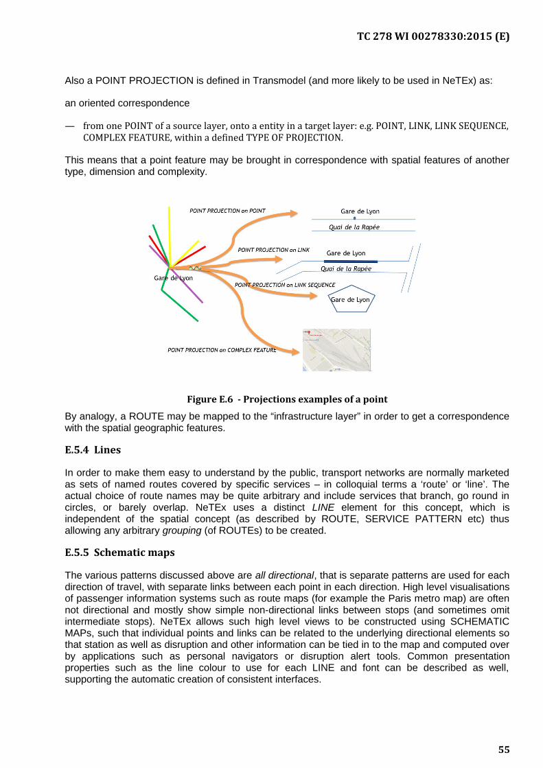
TC 278 WI 00278330:2015 (E)
Also a POINT PROJECTION is defined in Transmodel (and more likely to be used in NeTEx) as:
an oriented correspondence
— from one POINT of a source layer, onto a entity in a target layer: e.g. POINT, LINK, LINK SEQUENCE,COMPLEX FEATURE, within a defined TYPE OF PROJECTION.
This means that a point feature may be brought in correspondence with spatial features of anothertype, dimension and complexity.
Figure E.6 - Projections examples of a point
By analogy, a ROUTE may be mapped to the “infrastructure layer” in order to get a correspondencewith the spatial geographic features.
E.5.4 Lines
In order to make them easy to understand by the public, transport networks are normally marketedas sets of named routes covered by specific services – in colloquial terms a ‘route’ or ‘line’. Theactual choice of route names may be quite arbitrary and include services that branch, go round incircles, or barely overlap. NeTEx uses a distinct LINE element for this concept, which isindependent of the spatial concept (as described by ROUTE, SERVICE PATTERN etc) thusallowing any arbitrary grouping (of ROUTEs) to be created.
E.5.5 Schematic maps
The various patterns discussed above are all directional, that is separate patterns are used for eachdirection of travel, with separate links between each point in each direction. High level visualisationsof passenger information systems such as route maps (for example the Paris metro map) are oftennot directional and mostly show simple non-directional links between stops (and sometimes omitintermediate stops). NeTEx allows such high level views to be constructed using SCHEMATICMAPs, such that individual points and links can be related to the underlying directional elements sothat station as well as disruption and other information can be tied in to the map and computed overby applications such as personal navigators or disruption alert tools. Common presentationproperties such as the line colour to use for each LINE and font can be described as well,supporting the automatic creation of consistent interfaces.
55
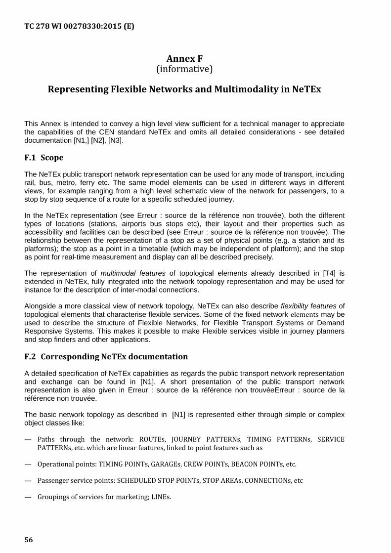
TC 278 WI 00278330:2015 (E)
Annex F(informative)
Representing Flexible Networks and Multimodality in NeTEx
This Annex is intended to convey a high level view sufficient for a technical manager to appreciatethe capabilities of the CEN standard NeTEx and omits all detailed considerations - see detaileddocumentation [N1,] [N2], [N3].
F.1 Scope
The NeTEx public transport network representation can be used for any mode of transport, includingrail, bus, metro, ferry etc. The same model elements can be used in different ways in differentviews, for example ranging from a high level schematic view of the network for passengers, to astop by stop sequence of a route for a specific scheduled journey.
In the NeTEx representation (see Erreur : source de la référence non trouvée), both the differenttypes of locations (stations, airports bus stops etc), their layout and their properties such asaccessibility and facilities can be described (see Erreur : source de la référence non trouvée). Therelationship between the representation of a stop as a set of physical points (e.g. a station and itsplatforms); the stop as a point in a timetable (which may be independent of platform); and the stopas point for real-time measurement and display can all be described precisely.
The representation of multimodal features of topological elements already described in [T4] isextended in NeTEx, fully integrated into the network topology representation and may be used forinstance for the description of inter-modal connections.
Alongside a more classical view of network topology, NeTEx can also describe flexibility features oftopological elements that characterise flexible services. Some of the fixed network elements may beused to describe the structure of Flexible Networks, for Flexible Transport Systems or DemandResponsive Systems. This makes it possible to make Flexible services visible in journey plannersand stop finders and other applications.
F.2 Corresponding NeTEx documentation
A detailed specification of NeTEx capabilities as regards the public transport network representationand exchange can be found in [N1]. A short presentation of the public transport networkrepresentation is also given in Erreur : source de la référence non trouvéeErreur : source de laréférence non trouvée.
The basic network topology as described in [N1] is represented either through simple or complexobject classes like:
— Paths through the network: ROUTEs, JOURNEY PATTERNs, TIMING PATTERNs, SERVICEPATTERNs, etc. which are linear features, linked to point features such as
— Operational points: TIMING POINTs, GARAGEs, CREW POINTs, BEACON POINTs, etc.
— Passenger service points: SCHEDULED STOP POINTs, STOP AREAs, CONNECTIONs, etc
— Groupings of services for marketing; LINEs.
56
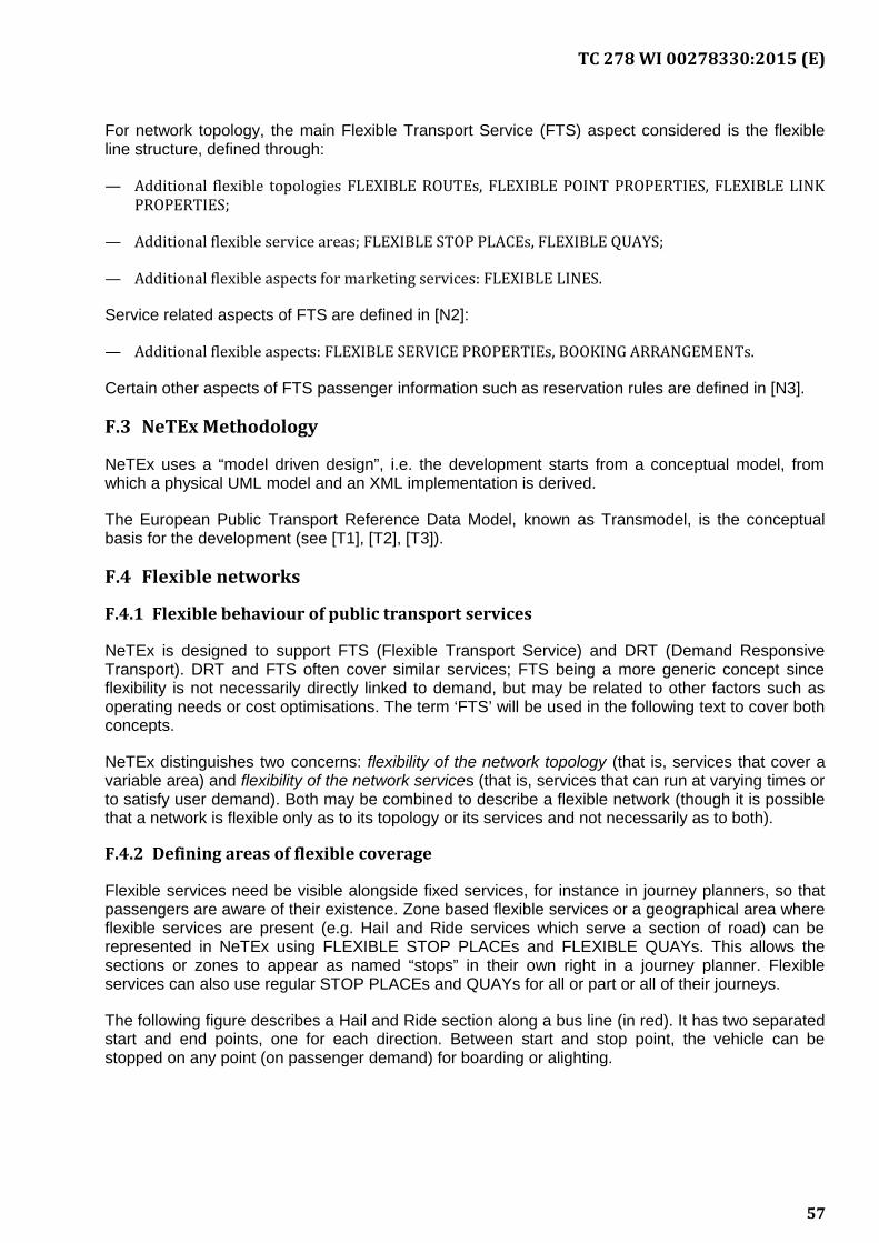
TC 278 WI 00278330:2015 (E)
For network topology, the main Flexible Transport Service (FTS) aspect considered is the flexibleline structure, defined through:
— Additional flexible topologies FLEXIBLE ROUTEs, FLEXIBLE POINT PROPERTIES, FLEXIBLE LINKPROPERTIES;
— Additional flexible service areas; FLEXIBLE STOP PLACEs, FLEXIBLE QUAYS;
— Additional flexible aspects for marketing services: FLEXIBLE LINES.
Service related aspects of FTS are defined in [N2]:
— Additional flexible aspects: FLEXIBLE SERVICE PROPERTIEs, BOOKING ARRANGEMENTs.
Certain other aspects of FTS passenger information such as reservation rules are defined in [N3].
F.3 NeTEx Methodology
NeTEx uses a “model driven design”, i.e. the development starts from a conceptual model, fromwhich a physical UML model and an XML implementation is derived.
The European Public Transport Reference Data Model, known as Transmodel, is the conceptualbasis for the development (see [T1], [T2], [T3]).
F.4 Flexible networks
F.4.1 Flexible behaviour of public transport services
NeTEx is designed to support FTS (Flexible Transport Service) and DRT (Demand ResponsiveTransport). DRT and FTS often cover similar services; FTS being a more generic concept sinceflexibility is not necessarily directly linked to demand, but may be related to other factors such asoperating needs or cost optimisations. The term ‘FTS’ will be used in the following text to cover bothconcepts.
NeTEx distinguishes two concerns: flexibility of the network topology (that is, services that cover avariable area) and flexibility of the network services (that is, services that can run at varying times orto satisfy user demand). Both may be combined to describe a flexible network (though it is possiblethat a network is flexible only as to its topology or its services and not necessarily as to both).
F.4.2 Defining areas of flexible coverage
Flexible services need be visible alongside fixed services, for instance in journey planners, so thatpassengers are aware of their existence. Zone based flexible services or a geographical area whereflexible services are present (e.g. Hail and Ride services which serve a section of road) can berepresented in NeTEx using FLEXIBLE STOP PLACEs and FLEXIBLE QUAYs. This allows thesections or zones to appear as named “stops” in their own right in a journey planner. Flexibleservices can also use regular STOP PLACEs and QUAYs for all or part or all of their journeys.
The following figure describes a Hail and Ride section along a bus line (in red). It has two separatedstart and end points, one for each direction. Between start and stop point, the vehicle can bestopped on any point (on passenger demand) for boarding or alighting.
57
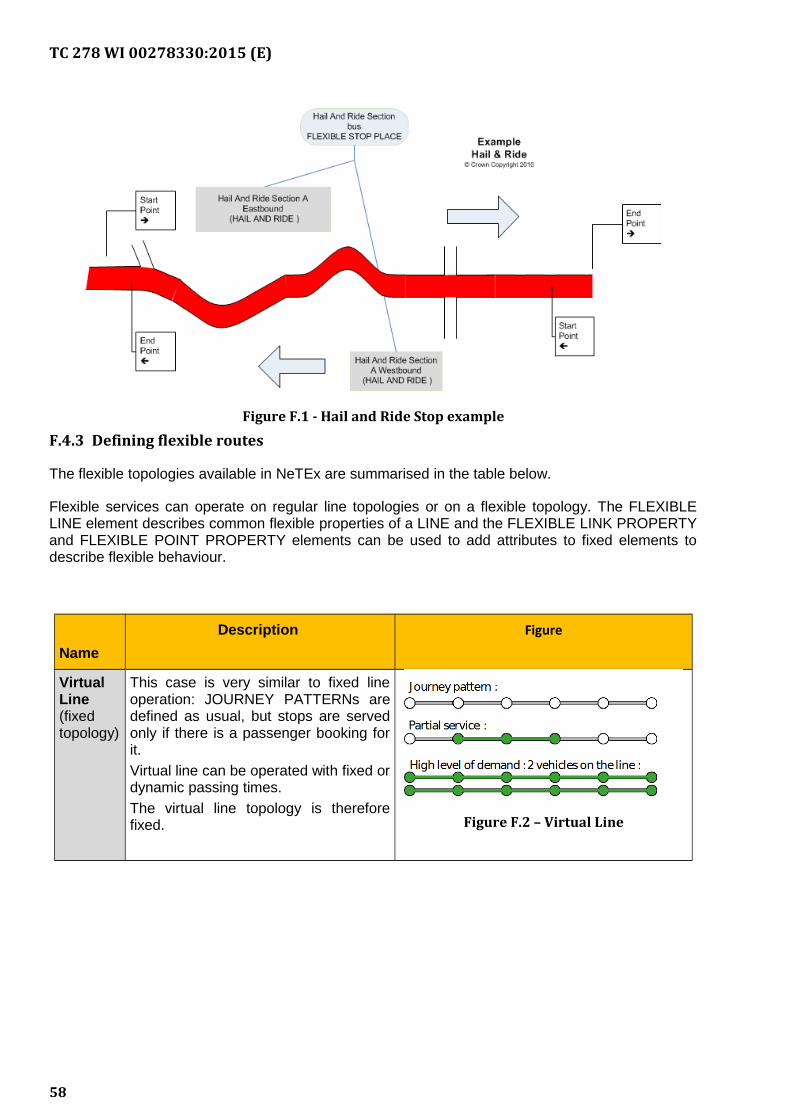
TC 278 WI 00278330:2015 (E)
Figure F.1 - Hail and Ride Stop example
F.4.3 Defining flexible routes
The flexible topologies available in NeTEx are summarised in the table below.
Flexible services can operate on regular line topologies or on a flexible topology. The FLEXIBLELINE element describes common flexible properties of a LINE and the FLEXIBLE LINK PROPERTYand FLEXIBLE POINT PROPERTY elements can be used to add attributes to fixed elements todescribe flexible behaviour.
Name
Description Figure
VirtualLine(fixedtopology)
This case is very similar to fixed lineoperation: JOURNEY PATTERNs aredefined as usual, but stops are servedonly if there is a passenger booking forit.
Virtual line can be operated with fixed ordynamic passing times.
The virtual line topology is thereforefixed. Figure F.2 – Virtual Line
58
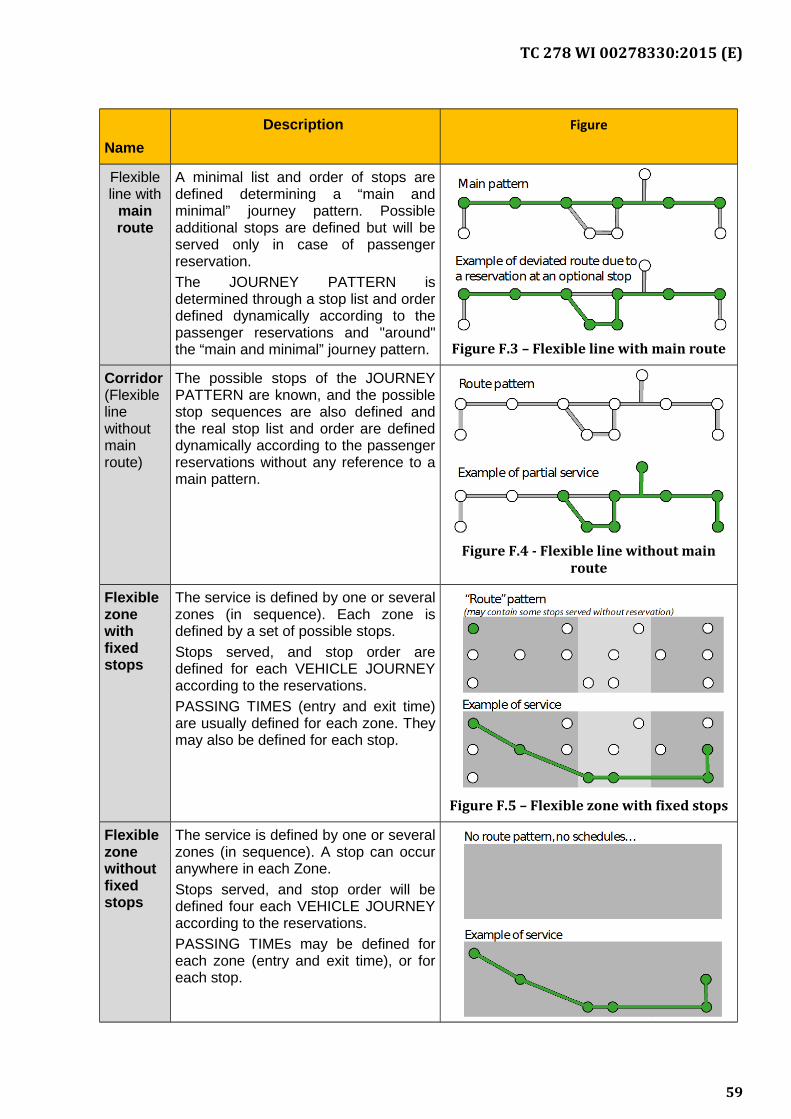
TC 278 WI 00278330:2015 (E)
Name
Description Figure
Flexibleline with
mainroute
A minimal list and order of stops aredefined determining a “main andminimal” journey pattern. Possibleadditional stops are defined but will beserved only in case of passengerreservation.
The JOURNEY PATTERN isdetermined through a stop list and orderdefined dynamically according to thepassenger reservations and "around"the “main and minimal” journey pattern. Figure F.3 – Flexible line with main route
Corridor(Flexiblelinewithoutmainroute)
The possible stops of the JOURNEYPATTERN are known, and the possiblestop sequences are also defined andthe real stop list and order are defineddynamically according to the passengerreservations without any reference to amain pattern.
Figure F.4 - Flexible line without mainroute
Flexiblezonewithfixedstops
The service is defined by one or severalzones (in sequence). Each zone isdefined by a set of possible stops.
Stops served, and stop order aredefined for each VEHICLE JOURNEYaccording to the reservations.
PASSING TIMES (entry and exit time)are usually defined for each zone. Theymay also be defined for each stop.
Figure F.5 – Flexible zone with fixed stops
Flexiblezonewithoutfixedstops
The service is defined by one or severalzones (in sequence). A stop can occuranywhere in each Zone.
Stops served, and stop order will bedefined four each VEHICLE JOURNEYaccording to the reservations.
PASSING TIMEs may be defined foreach zone (entry and exit time), or foreach stop.
59
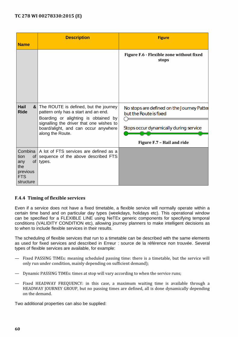
TC 278 WI 00278330:2015 (E)
Name
Description Figure
Figure F.6 - Flexible zone without fixedstops
Hail &Ride
The ROUTE is defined, but the journeypattern only has a start and an end.
Boarding or alighting is obtained bysignalling the driver that one wishes toboard/alight, and can occur anywherealong the Route.
Figure F.7 – Hail and ride
Combination ofany ofthepreviousFTSstructure
A lot of FTS services are defined as asequence of the above described FTStypes.
F.4.4 Timing of flexible services
Even if a service does not have a fixed timetable, a flexible service will normally operate within acertain time band and on particular day types (weekdays, holidays etc). This operational windowcan be specified for a FLEXIBLE LINE using NeTEx generic components for specifying temporalconditions (VALIDITY CONDITION etc), allowing journey planners to make intelligent decisions asto when to include flexible services in their results.
The scheduling of flexible services that run to a timetable can be described with the same elementsas used for fixed services and described in Erreur : source de la référence non trouvée. Severaltypes of flexible services are available, for example:
— Fixed PASSING TIMEs: meaning scheduled passing time: there is a timetable, but the service willonly run under condition, mainly depending on sufficient demand);
— Dynamic PASSING TIMEs: times at stop will vary according to when the service runs;
— Fixed HEADWAY FREQUENCY: in this case, a maximum waiting time is available through aHEADWAY JOURNEY GROUP, but no passing times are defined, all is done dynamically dependingon the demand.
Two additional properties can also be supplied:
60
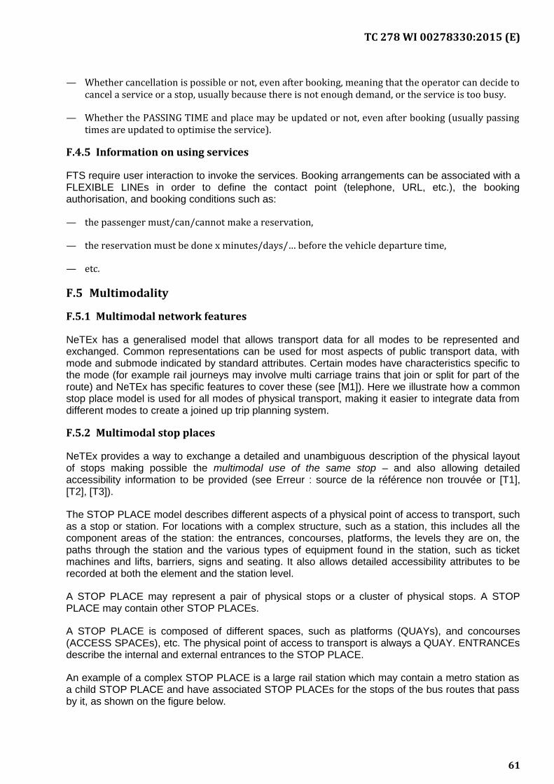
TC 278 WI 00278330:2015 (E)
— Whether cancellation is possible or not, even after booking, meaning that the operator can decide tocancel a service or a stop, usually because there is not enough demand, or the service is too busy.
— Whether the PASSING TIME and place may be updated or not, even after booking (usually passingtimes are updated to optimise the service).
F.4.5 Information on using services
FTS require user interaction to invoke the services. Booking arrangements can be associated with aFLEXIBLE LINEs in order to define the contact point (telephone, URL, etc.), the bookingauthorisation, and booking conditions such as:
— the passenger must/can/cannot make a reservation,
— the reservation must be done x minutes/days/… before the vehicle departure time,
— etc.
F.5 Multimodality
F.5.1 Multimodal network features
NeTEx has a generalised model that allows transport data for all modes to be represented andexchanged. Common representations can be used for most aspects of public transport data, withmode and submode indicated by standard attributes. Certain modes have characteristics specific tothe mode (for example rail journeys may involve multi carriage trains that join or split for part of theroute) and NeTEx has specific features to cover these (see [M1]). Here we illustrate how a commonstop place model is used for all modes of physical transport, making it easier to integrate data fromdifferent modes to create a joined up trip planning system.
F.5.2 Multimodal stop places
NeTEx provides a way to exchange a detailed and unambiguous description of the physical layoutof stops making possible the multimodal use of the same stop – and also allowing detailedaccessibility information to be provided (see Erreur : source de la référence non trouvée or [T1],[T2], [T3]).
The STOP PLACE model describes different aspects of a physical point of access to transport, suchas a stop or station. For locations with a complex structure, such as a station, this includes all thecomponent areas of the station: the entrances, concourses, platforms, the levels they are on, thepaths through the station and the various types of equipment found in the station, such as ticketmachines and lifts, barriers, signs and seating. It also allows detailed accessibility attributes to berecorded at both the element and the station level.
A STOP PLACE may represent a pair of physical stops or a cluster of physical stops. A STOPPLACE may contain other STOP PLACEs.
A STOP PLACE is composed of different spaces, such as platforms (QUAYs), and concourses(ACCESS SPACEs), etc. The physical point of access to transport is always a QUAY. ENTRANCEsdescribe the internal and external entrances to the STOP PLACE.
An example of a complex STOP PLACE is a large rail station which may contain a metro station asa child STOP PLACE and have associated STOP PLACEs for the stops of the bus routes that passby it, as shown on the figure below.
61
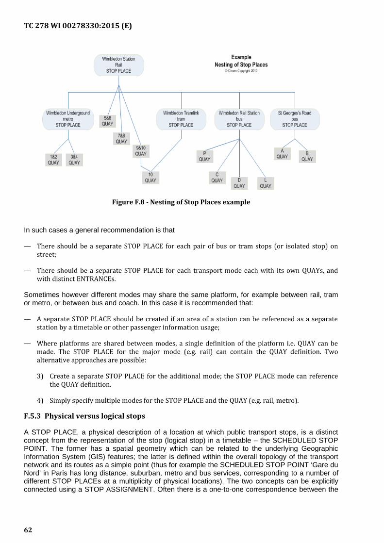
TC 278 WI 00278330:2015 (E)
Figure F.8 - Nesting of Stop Places example
In such cases a general recommendation is that
— There should be a separate STOP PLACE for each pair of bus or tram stops (or isolated stop) onstreet;
— There should be a separate STOP PLACE for each transport mode each with its own QUAYs, andwith distinct ENTRANCEs.
Sometimes however different modes may share the same platform, for example between rail, tramor metro, or between bus and coach. In this case it is recommended that:
— A separate STOP PLACE should be created if an area of a station can be referenced as a separatestation by a timetable or other passenger information usage;
— Where platforms are shared between modes, a single definition of the platform i.e. QUAY can bemade. The STOP PLACE for the major mode (e.g. rail) can contain the QUAY definition. Twoalternative approaches are possible:
3) Create a separate STOP PLACE for the additional mode; the STOP PLACE mode can referencethe QUAY definition.
4) Simply specify multiple modes for the STOP PLACE and the QUAY (e.g. rail, metro).
F.5.3 Physical versus logical stops
A STOP PLACE, a physical description of a location at which public transport stops, is a distinctconcept from the representation of the stop (logical stop) in a timetable – the SCHEDULED STOPPOINT. The former has a spatial geometry which can be related to the underlying GeographicInformation System (GIS) features; the latter is defined within the overall topology of the transportnetwork and its routes as a simple point (thus for example the SCHEDULED STOP POINT ‘Gare duNord’ in Paris has long distance, suburban, metro and bus services, corresponding to a number ofdifferent STOP PLACEs at a multiplicity of physical locations). The two concepts can be explicitlyconnected using a STOP ASSIGNMENT. Often there is a one-to-one correspondence between the
62
TC 278 WI 00278330:2015 (E)
two, and the same identifier is used for both (amounting to an implicit assignment), but in othercases – as say when a bus stop is moved, or a platform reassigned, or one transport mode uses adifferent set of identifiers from another mode, the use of separate elements for the separateconcepts allows a more precise representation (and also different assignments to be made to coverdifferent circumstances). In also enables detailed passenger information on interchange navigationto be provided (see Erreur : source de la référence non trouvée and Erreur : source de la référencenon trouvée).
F.5.4 Multimodal connection possibilities
The STOP PLACE model in particular allows the nature of the possible connections betweenservices that may be made at a transfer to be described very precisely and to be related to thephysical paths through the station, as well as the paths to access a station. This representation caninclude timing information for different times of day, allowing more accurate journey planning (seeconcepts of ACCESS and CONNECTION in Erreur : source de la référence non trouvée or [T1],[T2],[T3]).
Gathering such a data set for many large transfer locations requires a significant investment, so, aselsewhere, NeTEx allows an incremental approach to be taken. Global default values for transferpossibilities between modes on any SITE or OPERATOR, can be specified for where there is nomore specific value for a SITE.
63
TC 278 WI 00278330:2015 (E)
Annex G(informative)
Support for Accessibility in NeTEx
This Annex is intended to convey a high level view sufficient for a technical manager to appreciatethe capabilities of the CEN standard NeTEx for describing accessibility, and omits all detailedconsiderations that can be found in the detailed documentation see- (N1], [N2], [N3]).
G.1 Scope
The NeTEx public transport network representation can be used for any mode of transport, includingrail, bus, metro, ferry etc. (see Erreur : source de la référence non trouvée). The same modelelements can be used in different ways in different views, for example ranging from a high levelschematic view of the network for passengers, to a stop by stop sequence of a route for a specificscheduled journey (see Erreur : source de la référence non trouvée). Among the properties that canbe described are accessibility and facilities Thus both for of locations on the network (stations,airports bus stops etc), and transport services (on trains, buses etc) it is possible to specifyaccessibility data, including physical limitations, facilities and assistance services.
G.2 Corresponding NeTEx documentation
A detailed specification of NeTEx capabilities as regards the public transport network representationand exchange can be found in [N1].
In particular the accessibility properties of the network are mainly described as additional (space-related) aspects of the basic network (Erreur : source de la référence non trouvée) and also apply tovarious (time-related) aspects of the JOURNEYs described in Erreur : source de la référence nontrouvée, as summarised here:
The NeTEx Framework (section 1 of [N1]) includes some generic components describingaccessibility that are reused in other sections (see also [N2], [N3]), such as:
— Generic accessibility components: USER NEEDs, LIMITATIONS, SUITABILITIES, ACCESSBILITYASSESMENTs describe different types of user accessibility requirements (Wheelchair, Pushchair,Guide dog, Visual Impairment, Medical condition etc) as a standardized set of categories that can beused uniformly;
— VEHICLEs and VEHICLE TYPEs which can have their accessibility described through anEQUIPMENT PROFILE;
— EQUIPMENT: specific accessibility properties of SITES and VEHICLEs (for example Wheelchairaccessible Toilets, Lifts etc.), can be described using EQUIPMENT elements. These can bespecialised in other sections of NeTEx to create specific types of equipment;
— VALIDITY CONDITIONs can be used to set temporal and other conditions on availability.
Public Transport Network Topology (section 2 of [6]), describes elements of the Network to whichaccessibility can be applied:
64
TC 278 WI 00278330:2015 (E)
— Sites in the Network: STOP PLACEs, POINTs OF INTEREST, PARKINGs etc and their subcomponents(QUAYs, ENTRANCES, etc), as well as the paths (NAVIGATION PATHs) within them.
— Transfer points: TRANSFERs, CONNECTIONs, INTERCHANGEs.
Accessibility concepts also apply to some of the journey related entities described in [7]),
— Journeys: SERVICE JOURNEYs and JOURNEY PARTs may have facilities or EQUIPMENT associatedwith them that describes the accessibility features of a journey or part of a journey.
G.3 NeTEx Methodology
NeTEx uses a “model driven design”, i.e. the development starts from a conceptual model, fromwhich a physical UML model and an XML implementation is derived.
The European Public Transport Reference Data Model, known as Transmodel, is the conceptualbasis for the development (see [T1], [T2], [T3] and also [T4] which provides a detailed physicalmodel of stops).
G.4 Approach
NeTEx aims to use a uniform and standardized set of attributes to describe the accessibilityproperties of the network; this makes it possible to use such data in journey planners to computeconsistent results across the network.
Specifying all the possible accessibility characteristics of a network requires a sustained long termeffort to gather what is a large and quite complex data set; such a set will typically only be gatheredincrementally and unevenly over a network. Furthermore, the mandatory requirements for providingaccessibility data are subject to different legal requirements in different European countries, so arelikely to be achieved at different rates. The NeTEx model is accordingly designed to be usable atdifferent levels of detail; it can be populated sparsely at a high level to achieve a useful basic levelof function and then populated more richly to over time. When fully populated it enables a high levelof functionality including a detailed step by step representation of a path through an interchange.
To describe accessibility, NeTEx models as separate and distinct aspects:
(a) the description of the USER’s NEEDs – for example wheelchair, hearing impaired, visionimpaired, lift-averse, etc.; and
(b) the ACCESSIBILITY LIMITATION, of the location i.e. description of the limitations of aSITE ELEMENT to support a specific need, for example Wheelchair, Step free, Escalatorfree, Lift free .
These aspects can be grouped together as an ACCESSIBILITY ASSESSMENT and associated withvarious NeTEx ENTITies.
G.5 Accessibility of sites
NeTEx/Transmodel supports a detailed description of the accessibility of a SITE, i.e. of a location towhich passengers may wish to travel such as a station (STOP PLACE) or POINT OF INTEREST(the latter can be used to describe accessibility of public buildings, parks and other locations thatare not public transport nodes.)
65
TC 278 WI 00278330:2015 (E)
The accessibility of SITE components is described using an ACCESSIBILITY ASSESSMENT: thisallows any SITE component to be described either in terms of suitability for specific user needs or interms of accessibility limitations of the SITE, or both.
This can be used in applications in various ways:
— for journey planners when calculating a journey that meets a given set of user criteria, to choosestations or paths that are, for instance, wheelchair accessible when planning a point-to-pointjourney
— for trip preparation to show the exact properties of a given location, part of a planned trip so thatusers may make their own judgement about the opportunity to access this specific location.
In addition to the accessibility of SITEs, further information relevant for detailed accessibility iscontained on many of the different EQUIPMENT elements, for example, lift dimensions andcontrols, step heights, handrails and the number of steps in a staircase, ramp gradients, whetherbarriers are wheelchair passable, etc. LOCATION SERVICEs can be used to describe, ASSTANCESERVIES, porterage that may be invoked to assist travellers, including information on how to bookthem.
Information can be specified at a detailed SITE COMPONENT level and also at a summary level sothat an overall indication can be given for a SITE
G.6 Accessibility and connections
In order for a journey to be accessible, it must be possible not only to access a stop despite anymobility restrictions, but also to change services at each intermediate stop where a connection ismade between journeys. Users with mobility restrictions may need extra time to make a connection,either because they move slower, or because they have to take a different path within the transfersite. NeTEx allows accessibility and time conditions to be specified on individual connections so thatprecise journey plans can be computed that reflect the layout of complex interchanges such asmajor stations, where there can be material differences in the time needed to according to thespecific interchange. Generic defaults for a mode be used as a fall-back or useful approximationwhen exact data is not available.
We note that in colloquial usage, the terms ‘interchange’, ‘transfer’, ‘connection’, ‘access’ arecommonly used in the context of journey planning, but often with overlapping or ambiguous senses.To remove this ambiguity, Transmodel and thus NeTEx (as elsewhere), uses each term for adistinct, well defined concept so that the different aspects of journey interchanging can be modelledand computed over. In particular, the spatial passenger-oriented aspects are clearly separated fromoperation and time-related aspects.
— The terms TRANSFER, ACCESS and CONNECTION are passenger-oriented and space–relatedconcepts against which time constraints for a passenger to change from one public transportvehicle to another to continue the trip are expressed.
— INTERCHANGE is an operation–oriented time-related term expressing scheduled time constraints tobe respected between vehicle journeys.
Thus, to describe the characteristics of the network and its topology TRANSFER, ACCESS andCONNECTION are used. More precisely, a TRANSFER represents any pair of points locatedsufficiently near that there is a possibility of a passenger moving between them on a timescalewhich is realistic for carrying out a trip.
66
TC 278 WI 00278330:2015 (E)
— A CONNECTION is a type of TRANSFER between two SCHEDULED STOP POINTs or STOP AREAs.
— An ACCESS is a type of TRANSFER that represents the walking movement of a passenger at thebeginning or end of the trip from their origin/destination to a stop where he will board a publictransport vehicle.
It is possible to specify detailed timings and accessibility attributes for ACCESSEs andCONNECTIONs so that journey planners can make use of them.
G.7 Accessibility of navigation paths
ACCESSes and CONNECTIONs specify the possibility of a transfer but do not define the precisephysical paths to be taken. The specific ways of traversing a site are described by NAVIGATIONPATHs between any two points; these may be annotated with their accessibility characteristics sothat a journey planner can choose an accessible path.
Several different NAVIGATION PATHs may be associated with the same CONNECTION,representing alternative paths by which the CONNECTION can be walked;
Both concepts (CONNECTION and NAVIGATION PATH) allow to record times, but:
— CONNECTION transfer times relate to the timetabled connection times (and can be used withoutreference to actual platforms)
— NAVIGATION PATH transfer times relate to the known times to traverse between physical stops.
A NAVIGATION PATH is made up of PATH LINKs, each recording the accessibility characteristicsof an individual section in the path. These can include information on Lifts, Steps, lighting, handrails,surfaces (cobbled, tactile surfaces for the blind, etc) and other properties of interest to differentclasses of passenger. In order to make use of the information about accessibility in ACCESSes,the PATH LINKs, must typically be integrated with information about the wider geospatial contextwithin which the NAVIGATION PATH is connected, i.e. with the characteristics of the related roadelements. This part is not considered in detail in the model, only some of the infrastructure-relatedcharacteristics are explicitly mentioned.
G.8 Accessibility of journeys
The accessibility of a journey may also depend on the facilities of the actual vehicles used and onthe assistance services provided by the operator to mobility impaired users.
SERVICE JOURNEYs and JOURNEY PARTs may have facilities or EQUIPMENT associated withthem that describe the accessibility features of a journey or part of a journey. These may be derivedfrom a VEHICLE TYPE and its EQUIPMENT PROFILE, or be specified on a specific journey. Iffacilities are only available at certain times VALIDITY CONDITIONS can be used to specify this.
— The accessibility of specific services and VEHICLE JOURNEYs, (e.g. low floor access, on boardwheelchair spaces, wheelchair hosts) can be described using equipment elements such as VEHICLEACCESS EQUIPMENT and WHEELCHAIR ACCESS EQUIPMENT. In addition a number of otherequipment types have some accessibility attributes. A LOCAL SERVICE can be used to describeassistance services.
NeTEx can cover complex cases such as when only a specific part of the platform gives access to atrain, or where a stop is only accessible if a specific vehicle type is used.
67
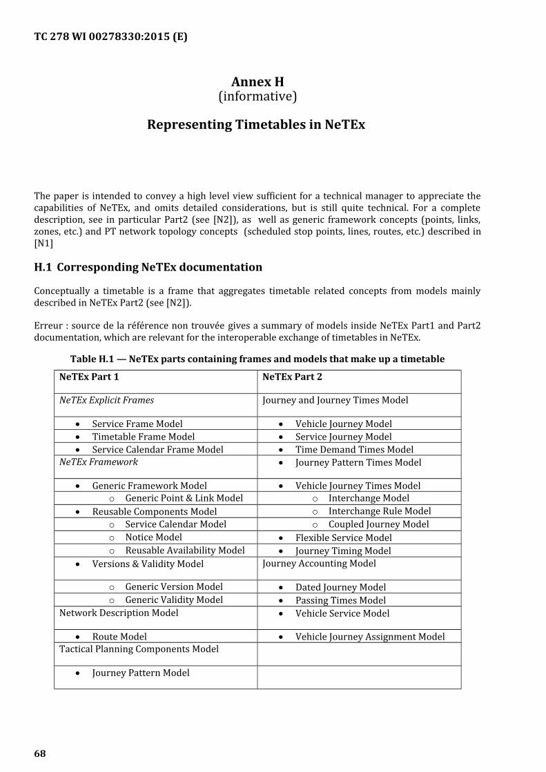
TC 278 WI 00278330:2015 (E)
Annex H(informative)
Representing Timetables in NeTEx
The paper is intended to convey a high level view sufficient for a technical manager to appreciate thecapabilities of NeTEx, and omits detailed considerations, but is still quite technical. For a completedescription, see in particular Part2 (see [N2]), as well as generic framework concepts (points, links,zones, etc.) and PT network topology concepts (scheduled stop points, lines, routes, etc.) described in[N1]
H.1 Corresponding NeTEx documentation
Conceptually a timetable is a frame that aggregates timetable related concepts from models mainlydescribed in NeTEx Part2 (see [N2]).
Erreur : source de la référence non trouvée gives a summary of models inside NeTEx Part1 and Part2documentation, which are relevant for the interoperable exchange of timetables in NeTEx.
Table H.1 — NeTEx parts containing frames and models that make up a timetable
NeTEx Part 1 NeTEx Part 2
NeTEx Explicit Frames Journey and Journey Times Model
Service Frame Model Vehicle Journey Model Timetable Frame Model Service Journey Model Service Calendar Frame Model Time Demand Times Model
NeTEx Framework Journey Pattern Times Model
Generic Framework Model Vehicle Journey Times Modelo Generic Point & Link Model o Interchange Model
Reusable Components Model o Interchange Rule Modelo Service Calendar Model o Coupled Journey Modelo Notice Model Flexible Service Modelo Reusable Availability Model Journey Timing Model
Versions & Validity Model Journey Accounting Model
o Generic Version Model Dated Journey Modelo Generic Validity Model Passing Times Model
Network Description Model Vehicle Service Model
Route Model Vehicle Journey Assignment ModelTactical Planning Components Model
Journey Pattern Model
68
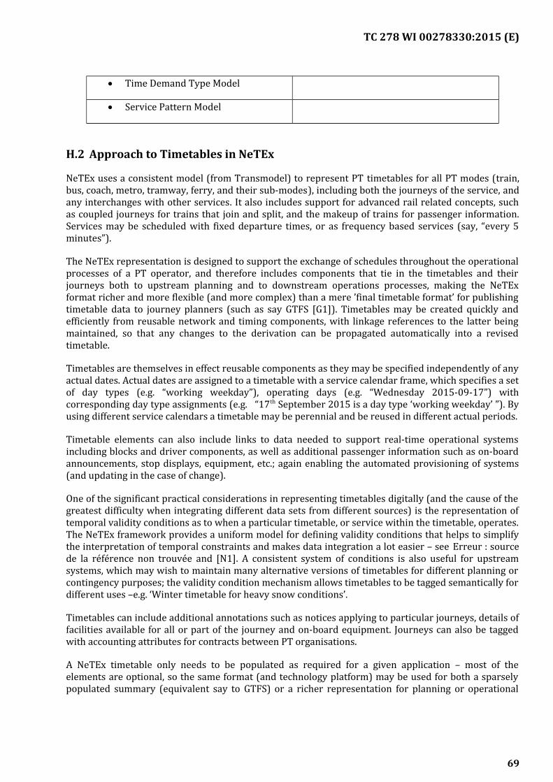
TC 278 WI 00278330:2015 (E)
Time Demand Type Model
Service Pattern Model
H.2 Approach to Timetables in NeTEx
NeTEx uses a consistent model (from Transmodel) to represent PT timetables for all PT modes (train,bus, coach, metro, tramway, ferry, and their sub-modes), including both the journeys of the service, andany interchanges with other services. It also includes support for advanced rail related concepts, suchas coupled journeys for trains that join and split, and the makeup of trains for passenger information.Services may be scheduled with fixed departure times, or as frequency based services (say, “every 5minutes”).
The NeTEx representation is designed to support the exchange of schedules throughout the operationalprocesses of a PT operator, and therefore includes components that tie in the timetables and theirjourneys both to upstream planning and to downstream operations processes, making the NeTExformat richer and more flexible (and more complex) than a mere ’final timetable format’ for publishingtimetable data to journey planners (such as say GTFS [G1]). Timetables may be created quickly andefficiently from reusable network and timing components, with linkage references to the latter beingmaintained, so that any changes to the derivation can be propagated automatically into a revisedtimetable.
Timetables are themselves in effect reusable components as they may be specified independently of anyactual dates. Actual dates are assigned to a timetable with a service calendar frame, which specifies a setof day types (e.g. “working weekday”), operating days (e.g. “Wednesday 2015-09-17”) withcorresponding day type assignments (e.g. “17th September 2015 is a day type ‘working weekday’ ”). Byusing different service calendars a timetable may be perennial and be reused in different actual periods.
Timetable elements can also include links to data needed to support real-time operational systemsincluding blocks and driver components, as well as additional passenger information such as on-boardannouncements, stop displays, equipment, etc.; again enabling the automated provisioning of systems(and updating in the case of change).
One of the significant practical considerations in representing timetables digitally (and the cause of thegreatest difficulty when integrating different data sets from different sources) is the representation oftemporal validity conditions as to when a particular timetable, or service within the timetable, operates.The NeTEx framework provides a uniform model for defining validity conditions that helps to simplifythe interpretation of temporal constraints and makes data integration a lot easier – see Erreur : sourcede la référence non trouvée and [N1]. A consistent system of conditions is also useful for upstreamsystems, which may wish to maintain many alternative versions of timetables for different planning orcontingency purposes; the validity condition mechanism allows timetables to be tagged semantically fordifferent uses –e.g. ‘Winter timetable for heavy snow conditions’.
Timetables can include additional annotations such as notices applying to particular journeys, details offacilities available for all or part of the journey and on-board equipment. Journeys can also be taggedwith accounting attributes for contracts between PT organisations.
A NeTEx timetable only needs to be populated as required for a given application – most of theelements are optional, so the same format (and technology platform) may be used for both a sparselypopulated summary (equivalent say to GTFS) or a richer representation for planning or operational
69
TC 278 WI 00278330:2015 (E)
purposes. There are mappings of timetable elements into major legacy formats such as VDV 452 andNEPTUNE.
Fares for scheduled services are added in NeTEx Part3, referencing the network and timetablecomponents developed in NeTEx Part1 (see [N1]) and NeTEx Part2 (see [N2]).
H.3 The representation of a timetable
NeTEx uses a conventional representation for the core timetable, corresponding to that found invarious national standards, which we outline in this section:
— A simple timetable is made up of one or more SERVICE JOURNEYs; each journey describing ascheduled journey departing at a specific time. A journey is made up of two or more CALLs, eachdescribing arrival and or departure times at a SCHEDULED STOP POINT in sequence, along withany other information relating to a visit to a particular stop, such as notices, platforms, displayheadings, accessibility of the service, etc. Validty conditions as to when a particular journey runsare normally specified in terms of DAY TYPEs types which can be separately resolved to an actualcalendar date.
— The journeys are grouped explicitly in a TIMETABLE FRAME, which sets global validity conditionsand other defaults for all SERVICE JOURNEYs in the timetable. The frame provides a container tohold the journeys and other timetable related elements for exchange. Timetable frames canthemselves be grouped in a COMPOSITE FRAME with other types of frame, for example SERVICEFRAMEs (with stop and route details), SERVICE CALENDAR FRAME (with DAY TYPEs andOPERATING DAYs) and/or FARE FRAMEs (with price details) in order to create complete andcoherent self-contained data sets. DAY TYPE is used to specify the days one which a given serviceruns; the temporal constraints on the DAY TYPE can be specified by VALIDITY CONDITIONs thatspecify the day of week, holiday operation, etc.
NeTEx has many additional features to represent additional aspects of timetables that are found indifferent circumstances:
— To represent frequency based services; an additional types of service journey, the TEMPLATESERVICE JOURNEY, is provided. The frequency may be specified either as an interval such as “everyfive to ten minutes’” (using a HEADWAY JOURNEY GROUP) or a as a regular e.g. “at 05, 25 and 45minutes past the hour” (using a RHYTHMICAL JOURNEY GROUP). Use of a separate templatecomponent clarifies the distinction between the operational view of the timetable (which stillinvolves individual SERVICE JOURNEYs running at specific times in operational blocks) from thepassenger view, which is condensed down to a single entry with a frequency.
— PT services will often be planned so as to connect with other services, and information on theseconnections may be included in passenger information using the SERVICE JOURNEY INTERCHANGEelement. The representation can describe interchange times and whether a connection isadvertised, guaranteed (i.e. will wait a certain time) and other operational constraints. Additionalcomplex conditions about managing journey interchanges can be specified with INTERCHANGERULEs.
— Long distance rail may involve vehicle journeys that join or split; this can be modelled by theadditional use of JOURNEY PART elements, to represent each segment of the journey which can becombined as JOURNEY PART COUPLEs to indicate a joined segment of the journey. TRAIN &COMPOUND TRAIN ELEMENTS can be used to describe the corresponding train makeup
70
TC 278 WI 00278330:2015 (E)
implications (i.e. which carriages go where) so that meaningful passenger information can beprovided. The TRAIN NUMBER element allows the correct public identifier used for each journey tobe provided, despite any intricacies of joining or splitting or international operation.
H.3.1 Components to create a timetable
The operation of modern PT networks typically involves the use of computer based systems to plan andoptimise the provision of services. Planning systems represent (and may need to change) not just thetimetable element but also the various elements from which the timetable is built. NeTEx allows suchdata to be exchanged, as well as the resulting timetables. Here we outline the relationship of suchelements to the timetable.
— The central timetable element is the VEHICLE JOURNEY (a generalization of SERVICE JOURNEY),which is a combination of a number of different tactical components: (a) the ROUTE and relatedJOURNEY PATTERN and SERVICE PATTERN, which dictate the route and sequence of stops(POINTs IN SEQUENCE) to be followed; (b) the TIMING PATTERN, and JOURNEY TIMINGs, whichgive the timing points and times needed to cover each link of the journey, and (c) the TIMEDEMAND TYPE, which specifies the part of day that the journey is taking place, e.g. ‘weekday’, ‘rushhour’, etc. and so which set of timings should be used. Thus given a starting time and a SERVICEPATTERN it is possible to integrate information from the other components and automaticallycompute a sequence of CALLs with PASSING TIMES etc. at each stop.
— The planning of services may also involve the optimisation of groups of journeys in driver andvehicle scheduling systems, to create work periods for each VEHICLE TYPE. Such periods aredescribed as BLOCKs, worked from a PARKING POINT to another, composed of sets of VEHICLEJOURNEYs. BLOCKs may be coupled (building COMPOUND BLOCKs, representing the work of avehicle during the time it is coupled to another vehicle) or separated for a while, building BLOCKPARTs, i.e. the parts of a BLOCK corresponding to the different JOURNEY PARTs of the VEHICLEJOURNEYs in a BLOCK.
— A DEAD RUN is another type of VEHICLE JOURNEY, an out of service journey that send out vehiclesand retrieve them back to their depots, these may included to support operational and real-timesystems.
H.3.2 Components to operate a timetable
Other types of operational data may be included in the SERVICE JOURNEY representation to provisiondownstream systems. For example:
— JOURNEY ACCOUNTING elements can be used to apportion costs for providing services for (partsof) a journey for contracts between different organizations.
— DESTINATION DISPLAY elements can be used to drive headsign, on-board displays and next stopannouncements along the journey.
H.4 Example of a simple timetable in NeTEx
The example (Erreur : source de la référence non trouvéeH.1) shows a simple bus timetable for a linearroute modelled in NeTEx. The example originates from a national PT database in Slovenia.
— The timetable includes two ROUTES (outbound – “Briga to Nova sela” and inbound – “Nova sela toBriga”) belonging to one LINE (id=K66, “Kočevje – Petrina”) with transport MODE “bus”.
71
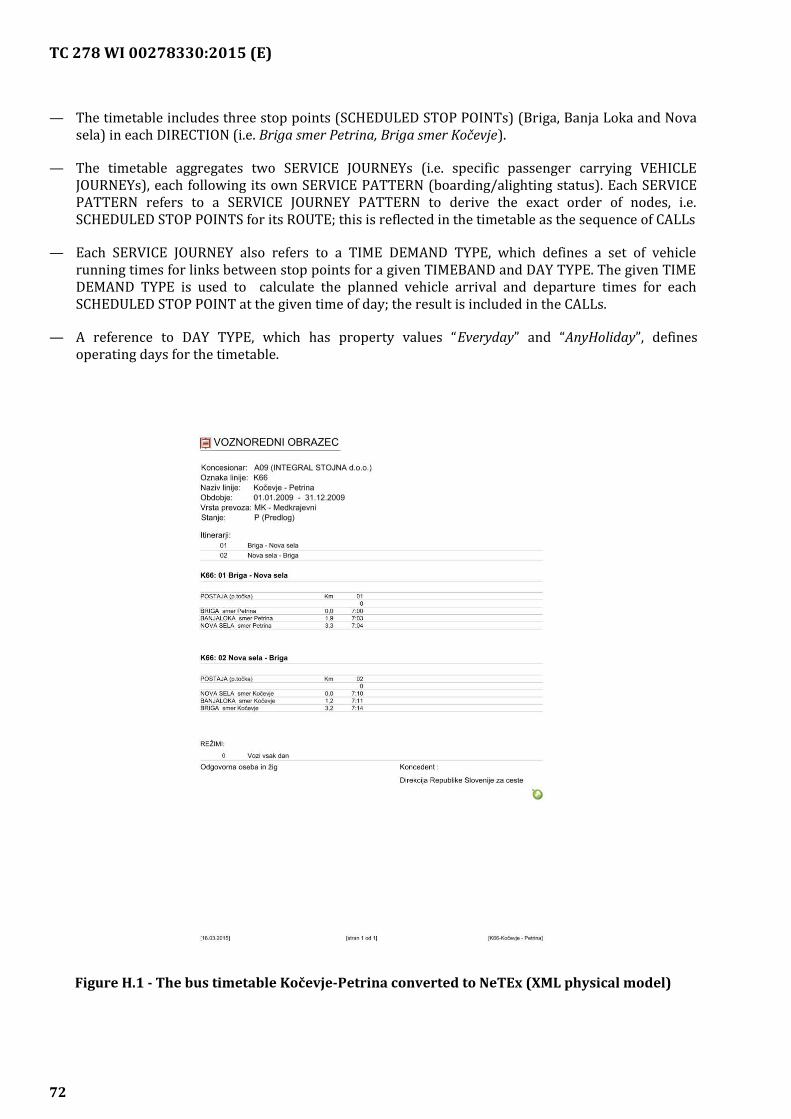
TC 278 WI 00278330:2015 (E)
— The timetable includes three stop points (SCHEDULED STOP POINTs) (Briga, Banja Loka and Novasela) in each DIRECTION (i.e. Briga smer Petrina, Briga smer Kočevje).
— The timetable aggregates two SERVICE JOURNEYs (i.e. specific passenger carrying VEHICLEJOURNEYs), each following its own SERVICE PATTERN (boarding/alighting status). Each SERVICEPATTERN refers to a SERVICE JOURNEY PATTERN to derive the exact order of nodes, i.e.SCHEDULED STOP POINTS for its ROUTE; this is reflected in the timetable as the sequence of CALLs
— Each SERVICE JOURNEY also refers to a TIME DEMAND TYPE, which defines a set of vehiclerunning times for links between stop points for a given TIMEBAND and DAY TYPE. The given TIMEDEMAND TYPE is used to calculate the planned vehicle arrival and departure times for eachSCHEDULED STOP POINT at the given time of day; the result is included in the CALLs.
— A reference to DAY TYPE, which has property values “Everyday” and “AnyHoliday”, definesoperating days for the timetable.
Figure H.1 - The bus timetable Kočevje-Petrina converted to NeTEx (XML physical model)
72
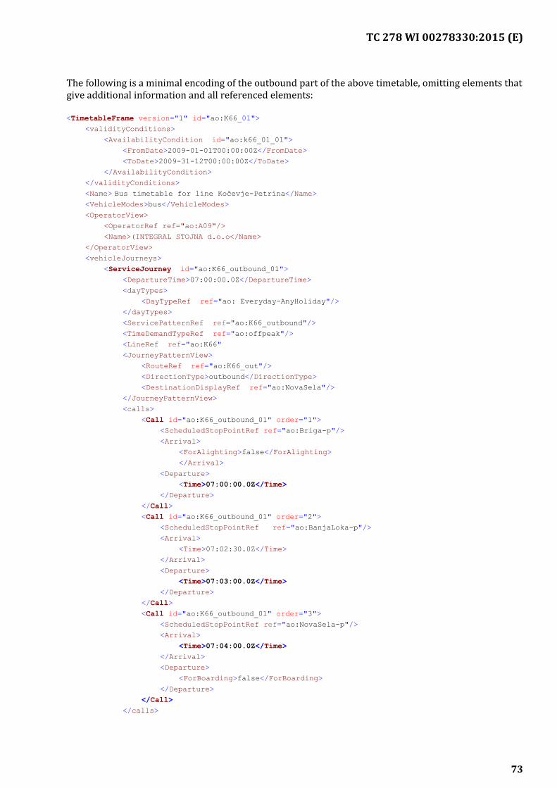
TC 278 WI 00278330:2015 (E)
The following is a minimal encoding of the outbound part of the above timetable, omitting elements thatgive additional information and all referenced elements:
<TimetableFrame version="1" id="ao:K66_01">
<validityConditions>
<AvailabilityCondition id="ao:k66_01_01">
<FromDate>2009-01-01T00:00:00Z</FromDate>
<ToDate>2009-31-12T00:00:00Z</ToDate>
</AvailabilityCondition>
</validityConditions>
<Name> Bus timetable for line Kočevje-Petrina</Name><VehicleModes>bus</VehicleModes>
<OperatorView>
<OperatorRef ref="ao:A09"/>
<Name>(INTEGRAL STOJNA d.o.o</Name>
</OperatorView>
<vehicleJourneys>
<ServiceJourney id="ao:K66_outbound_01">
<DepartureTime>07:00:00.0Z</DepartureTime>
<dayTypes>
<DayTypeRef ref="ao: Everyday-AnyHoliday"/>
</dayTypes>
<ServicePatternRef ref="ao:K66_outbound"/>
<TimeDemandTypeRef ref="ao:offpeak"/>
<LineRef ref="ao:K66"
<JourneyPatternView>
<RouteRef ref="ao:K66_out"/>
<DirectionType>outbound</DirectionType>
<DestinationDisplayRef ref="ao:NovaSela"/>
</JourneyPatternView>
<calls>
<Call id="ao:K66_outbound_01" order="1">
<ScheduledStopPointRef ref="ao:Briga-p"/>
<Arrival>
<ForAlighting>false</ForAlighting>
</Arrival>
<Departure>
<Time>07:00:00.0Z</Time>
</Departure>
</Call>
<Call id="ao:K66_outbound_01" order="2">
<ScheduledStopPointRef ref="ao:BanjaLoka-p"/>
<Arrival>
<Time>07:02:30.0Z</Time>
</Arrival>
<Departure>
<Time>07:03:00.0Z</Time>
</Departure>
</Call>
<Call id="ao:K66_outbound_01" order="3">
<ScheduledStopPointRef ref="ao:NovaSela-p"/>
<Arrival>
<Time>07:04:00.0Z</Time>
</Arrival>
<Departure>
<ForBoarding>false</ForBoarding>
</Departure>
</Call>
</calls>
73

TC 278 WI 00278330:2015 (E)
</ServiceJourney>
</vehicleJourneys>
</TimetableFrame>
74
TC 278 WI 00278330:2015 (E)
Annex I(informative)
Representing Fares in NeTEx
This Annex is intended to convey a high level view sufficient for a technical manager to appreciatethe capabilities of the CEN standard NeTEx and omits all detailed considerations - see detaileddocumentation [N1], [N2], and in particular for fares, [N3].
I.1 Scope
NeTEx Part3 [N3] covers fare data and is the main focus of this white paper; it is concerned withdata for the following purposes:
d) To describe the many and various possible fare structures that arise in public transport (forexample, flat fares, zonal fares, time-dependent fares, distance based fares, stage fares, pay as yougo fares, season passes, etc.).
e) To describe the fare products that may be purchased having these fare structures and to describethe conditions that may be attached to particular fares, for example if restricted to specific groupsof users, or subject to temporal restrictions. These conditions may be complex.
f) To allow actual fare price data to be exchanged. Note however that NeTEx does not itself specifypricing algorithms or how fares should be calculated. This is the concern of Fare ManagementSystems. It may be used however to exchange various parameters required for pricing calculationsthat are needed to explain or justify a fare, and each price may indicate their derivation fromanother price using a named method.
g) To include the attributes and the text descriptions necessary to present fares and their conditionsof sale and use to the public. The conditions are in a machine readable from that an applicationprogram may utilize.
I.2 Functional areas
The Transmodel model [T1], [T2], [T3], on which NeTEx is based, breaks down “fare collection” intothe following functional areas:
I.2.1 Fare policy specification:
— Characterisation of different fare structures through spatial and/or temporal parameters (e.g.sections, zones, time periods, etc.).
— Specification of the access rights allowed on a network, i.e. access to services provided on atransport network (e.g. trip on the metro network, trip on the bus network, access to the 1 st classwaiting area, etc. ) within a fare structure and the ways of using them (e.g. trip on the metronetwork during a time period of 2 hours, without successive on-board validations, trip on an openbus network during 1h30 with mandatory on-board validations and with the obligation to show anentitlement to use this right).
75
TC 278 WI 00278330:2015 (E)
— Specification of combinations of marketable access rights, called fare products (e.g. serviceconsumption rights granted through a simple ticket), being possibly combinations of access rightsdetermined by different fare.
— Description of sale principles applied to the fare products (e.g. specification of fare products sold asa sales package, and parameters describing the purchase rights, as for instance the obligation toshow an entitlement to purchase a certain fare product).
Sales management:
— Management of the sales network (not covered by Transmodel V5.1).
— Sales operations (including fulfilment) (partly covered by Transmodel V5.1).
— NeTEx for Basic Rail fare data NeTEx & TAP TSI - V0.6-Draft.docx Page 13 Management ofcustomers (partly covered by Transmodel V5.1).
— Collecting funds or accounting (not covered by Transmodel V5.1).
Pricing:
— Pricing parameters specification (partly covered by Transmodel V5.1).
— Exact price calculation (not covered by Transmodel).
Consumption control:
— Access right validation & control (covered by Transmodel V5.1).
— Fraud management (partly covered by Transmodel).
— Collection and aggregation of consumption data (not covered by Transmodel V5.1).
— Management of revenue sharing and clearing house activities (not covered in Transmodel V5.1).
I.3 Provision of information on fares
NeTEx covers only certain of the “upstream” processes of fare management sufficient to providepassenger information on fares; it is not concerned with reservation and ticketing processes. Thus“Fare policy specification” and “Provision of information on fares” are in the scope of NeTEx.“Pricing”, limited to “pricing parameters specification” is part of NeTEx and represents an extensionto Transmodel V5.1 (see [T1]). Collection and aggregation of consumption data is also in the scopeof NeTEx. Sales Management, Consumption control and other downstream process are outside thescope.
The following diagram summarises this
76
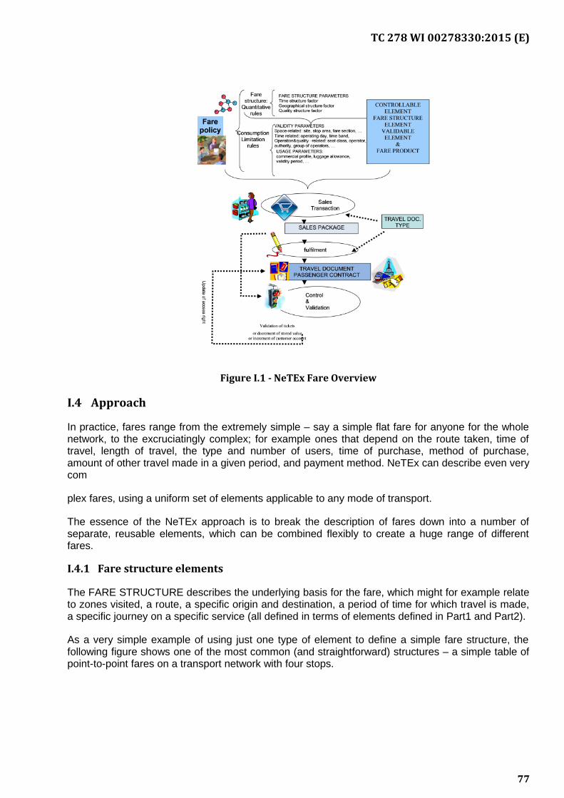
TC 278 WI 00278330:2015 (E)
Figure I.1 - NeTEx Fare Overview
I.4 Approach
In practice, fares range from the extremely simple – say a simple flat fare for anyone for the wholenetwork, to the excruciatingly complex; for example ones that depend on the route taken, time oftravel, length of travel, the type and number of users, time of purchase, method of purchase,amount of other travel made in a given period, and payment method. NeTEx can describe even verycom
plex fares, using a uniform set of elements applicable to any mode of transport.
The essence of the NeTEx approach is to break the description of fares down into a number ofseparate, reusable elements, which can be combined flexibly to create a huge range of differentfares.
I.4.1 Fare structure elements
The FARE STRUCTURE describes the underlying basis for the fare, which might for example relateto zones visited, a route, a specific origin and destination, a period of time for which travel is made,a specific journey on a specific service (all defined in terms of elements defined in Part1 and Part2).
As a very simple example of using just one type of element to define a simple fare structure, thefollowing figure shows one of the most common (and straightforward) structures – a simple table ofpoint-to-point fares on a transport network with four stops.
77
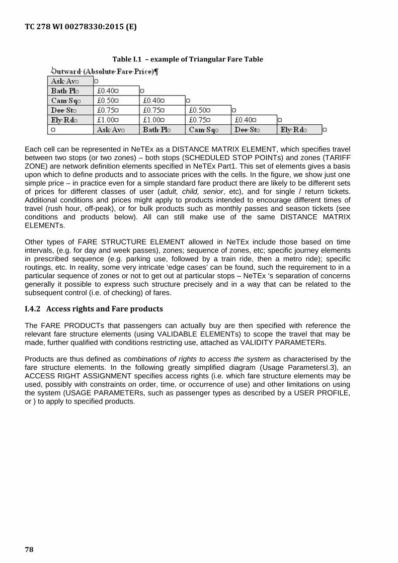
TC 278 WI 00278330:2015 (E)
Table I.1 – example of Triangular Fare Table
Each cell can be represented in NeTEx as a DISTANCE MATRIX ELEMENT, which specifies travelbetween two stops (or two zones) – both stops (SCHEDULED STOP POINTs) and zones (TARIFFZONE) are network definition elements specified in NeTEx Part1. This set of elements gives a basisupon which to define products and to associate prices with the cells. In the figure, we show just onesimple price – in practice even for a simple standard fare product there are likely to be different setsof prices for different classes of user (adult, child, senior, etc), and for single / return tickets.Additional conditions and prices might apply to products intended to encourage different times oftravel (rush hour, off-peak), or for bulk products such as monthly passes and season tickets (seeconditions and products below). All can still make use of the same DISTANCE MATRIXELEMENTs.
Other types of FARE STRUCTURE ELEMENT allowed in NeTEx include those based on timeintervals, (e.g. for day and week passes), zones; sequence of zones, etc; specific journey elementsin prescribed sequence (e.g. parking use, followed by a train ride, then a metro ride); specificroutings, etc. In reality, some very intricate ‘edge cases’ can be found, such the requirement to in aparticular sequence of zones or not to get out at particular stops – NeTEx ‘s separation of concernsgenerally it possible to express such structure precisely and in a way that can be related to thesubsequent control (i.e. of checking) of fares.
I.4.2 Access rights and Fare products
The FARE PRODUCTs that passengers can actually buy are then specified with reference therelevant fare structure elements (using VALIDABLE ELEMENTs) to scope the travel that may bemade, further qualified with conditions restricting use, attached as VALIDITY PARAMETERs.
Products are thus defined as combinations of rights to access the system as characterised by thefare structure elements. In the following greatly simplified diagram (Usage ParametersI.3), anACCESS RIGHT ASSIGNMENT specifies access rights (i.e. which fare structure elements may beused, possibly with constraints on order, time, or occurrence of use) and other limitations on usingthe system (USAGE PARAMETERs, such as passenger types as described by a USER PROFILE,or ) to apply to specified products.
78
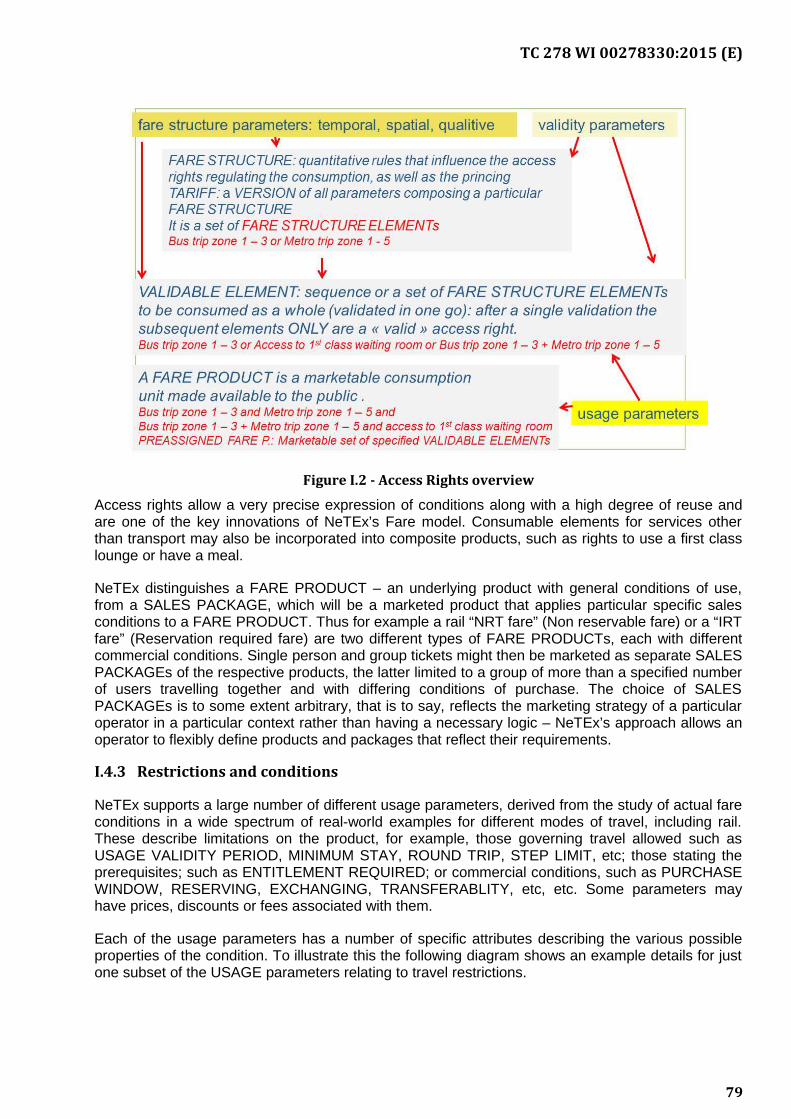
TC 278 WI 00278330:2015 (E)
Figure I.2 - Access Rights overview
Access rights allow a very precise expression of conditions along with a high degree of reuse andare one of the key innovations of NeTEx’s Fare model. Consumable elements for services otherthan transport may also be incorporated into composite products, such as rights to use a first classlounge or have a meal.
NeTEx distinguishes a FARE PRODUCT – an underlying product with general conditions of use,from a SALES PACKAGE, which will be a marketed product that applies particular specific salesconditions to a FARE PRODUCT. Thus for example a rail “NRT fare” (Non reservable fare) or a “IRTfare” (Reservation required fare) are two different types of FARE PRODUCTs, each with differentcommercial conditions. Single person and group tickets might then be marketed as separate SALESPACKAGEs of the respective products, the latter limited to a group of more than a specified numberof users travelling together and with differing conditions of purchase. The choice of SALESPACKAGEs is to some extent arbitrary, that is to say, reflects the marketing strategy of a particularoperator in a particular context rather than having a necessary logic – NeTEx’s approach allows anoperator to flexibly define products and packages that reflect their requirements.
I.4.3 Restrictions and conditions
NeTEx supports a large number of different usage parameters, derived from the study of actual fareconditions in a wide spectrum of real-world examples for different modes of travel, including rail.These describe limitations on the product, for example, those governing travel allowed such asUSAGE VALIDITY PERIOD, MINIMUM STAY, ROUND TRIP, STEP LIMIT, etc; those stating theprerequisites; such as ENTITLEMENT REQUIRED; or commercial conditions, such as PURCHASEWINDOW, RESERVING, EXCHANGING, TRANSFERABLITY, etc, etc. Some parameters mayhave prices, discounts or fees associated with them.
Each of the usage parameters has a number of specific attributes describing the various possibleproperties of the condition. To illustrate this the following diagram shows an example details for justone subset of the USAGE parameters relating to travel restrictions.
79
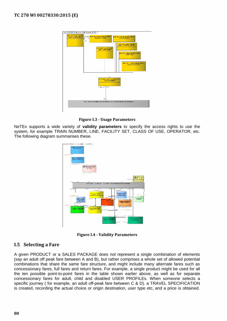
TC 278 WI 00278330:2015 (E)
Figure I.3 - Usage Parameters
NeTEx supports a wide variety of validity parameters to specify the access rights to use thesystem, for example TRAIN NUMBER, LINE, FACILITY SET, CLASS OF USE, OPERATOR, etc.The following diagram summarises these.
Figure I.4 - Validity Parameters
I.5 Selecting a Fare
A given PRODUCT or a SALES PACKAGE does not represent a single combination of elements(say an adult off peak fare between A and B), but rather comprises a whole set of allowed potentialcombinations that share the same fare structure, and might include many alternate fares such asconcessionary fares, full fares and return fares. For example, a single product might be used for allthe ten possible point-to-point fares in the table shown earlier above, as well as for separateconcessionary fares for adult, child and disabled USER PROFILEs. When someone selects aspecific journey ( for example, an adult off-peak fare between C & D). a TRAVEL SPECIFICATIONis created, recording the actual choice or origin destination, user type etc, and a price is obtained.
80
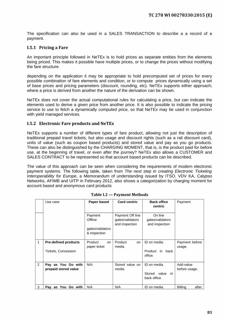
TC 278 WI 00278330:2015 (E)
The specification can also be used in a SALES TRANSACTION to describe a a record of apayment.
I.5.1 Pricing a Fare
An important principle followed in NeTEx is to hold prices as separate entities from the elementsbeing priced. This makes it possible have multiple prices, or to change the prices without modifyingthe fare structure.
depending on the application it may be appropriate to hold precomputed set of prices for everypossible combination of fare elements and condition, or to compute prices dynamically using a setof base prices and pricing parameters (discount, rounding, etc). NeTEx supports either approach;where a price is derived from another the nature of the derivation can be shown.
NeTEx does not cover the actual computational rules for calculating a price, but can indicate theelements used to derive a given price from another price. It is also possible to indicate the pricingservice to use to fetch a dynamically computed price, so that NeTEx may be used in conjunctionwith yield managed services.
I.5.2 Electronic Fare products and NeTEx
NeTEx supports a number of different types of fare product, allowing not just the description oftraditional prepaid travel tickets, but also usage and discount rights (such as a rail discount card),units of value (such as coupon based products) and stored value and pay as you go products.These can also be distinguished by the CHARGING MOMENT, that is, is the product paid for beforeuse, at the beginning of travel, or even after the journey? NeTEx also allows a CUSTOMER andSALES CONTRACT to be represented so that account based products can be described.
The value of this approach can be seen when considering the requirements of modern electronicpayment systems. The following table, taken from The next step in creating Electronic TicketingInteroperability for Europe, a Memorandum of understanding issued by ITSO, VDV KA, CalypsoNetworks, AFIMB and UITP in February 2012, also shows a categorization by charging moment foraccount based and anonymous card products
Table I.2 — Payment Methods
Use case Paper based Card centric Back officecentric
Payment
PaymentOffline
gates/validators& inspection
Payment Off linegates/validatorsand inspection
On linegates/validatorsand inspection
1 Pre-defined products
Tickets, Concession
Product onpaper ticket
Product onmedia
ID on media.
Product in backoffice.
Payment beforeusage.
2 Pay as You Go withprepaid stored value
N/A Stored value onmedia
ID on media.
Stored value inback office.
Add-valuebefore usage.
3 Pay as You Go with N/A N/A ID on media. Billing after
81
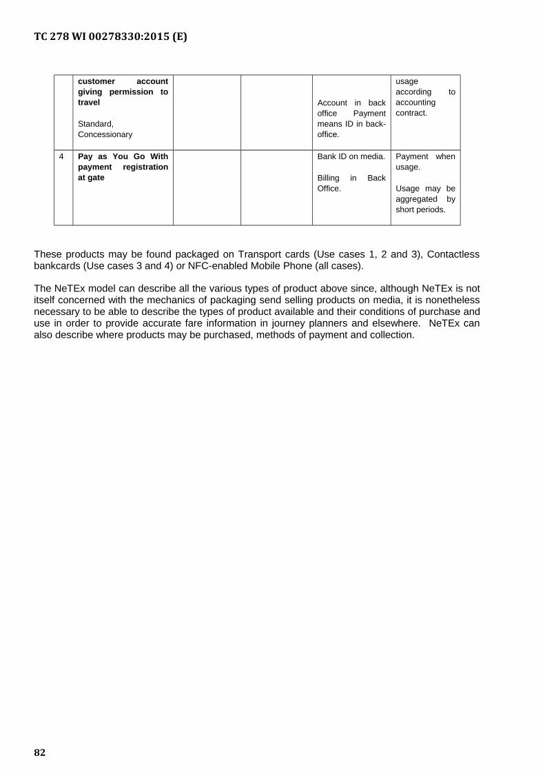
TC 278 WI 00278330:2015 (E)
customer accountgiving permission totravel
Standard,Concessionary
Account in backoffice Paymentmeans ID in back-office.
usageaccording toaccountingcontract.
4 Pay as You Go Withpayment registrationat gate
Bank ID on media.
Billing in BackOffice.
Payment whenusage.
Usage may beaggregated byshort periods.
These products may be found packaged on Transport cards (Use cases 1, 2 and 3), Contactlessbankcards (Use cases 3 and 4) or NFC-enabled Mobile Phone (all cases).
The NeTEx model can describe all the various types of product above since, although NeTEx is notitself concerned with the mechanics of packaging send selling products on media, it is nonethelessnecessary to be able to describe the types of product available and their conditions of purchase anduse in order to provide accurate fare information in journey planners and elsewhere. NeTEx canalso describe where products may be purchased, methods of payment and collection.
82
TC 278 WI 00278330:2015 (E)
Bibliography
The NeTEx Standard
[N1] NeTEx- Part 1: Public Transport Network Topology exchange format, CEN/TS 16614-1:2014,
[N2] NeTEx- Part 2: Public Transport Scheduled Timetables exchange format, CEN/TS 16614-2:2014,
[N3] NeTEx-Part 3: Fare Information exchange format, CEN/TS 16614-3:2015.
Other References
[E1] ERA TAP-TSI: Commission Regulation (EU) No 454/2011 of 5 May 2011 on the technicalspecificationfor interoperability relating to the subsystem ‘telematics applications forpassenger services’ of the trans-European rail system
[S1] CEN/TS 15531-1, Public transport - Service interface for real-time information relating topublictransport operations - Part 1: Context and framework
[S2] CEN/TS 15531-2, Public transport - Service interface for real-time information relating topublictransport operations - Part 2: Communications infrastructure
[S3] CEN/TS 15531-3, Public transport - Service interface for real-time information relating topublictransport operations - Part 3: Functional service interfaces
[S4] CEN/TS 15531-4, Public transport - Service interface for real-time information relating topublictransport operations - Part 4: Functional service interfaces: Facility Monitoring
[S5] CEN/TS 15531-5, Public transport - Service interface for real-time information relating topublic transport operations - Part 5: Functional service interfaces - Situation Exchange
[T1] Public Transport Reference Data Model – Part 1: Common Concepts (Transmodel),EN12896-1
[T2] Public Transport Reference Data Model –Part 2: Public Transport Network (Transmodel),EN12896-2
[T3] Public Transport Reference Data Model – Part 3: Timing Information and Vehicle Scheduling(Transmodel), EN12896-3
[G1] General Transport Feed Specification https://developers.google.com/transit/gtfs/
[I1] EN 28701, Road transport and traffic telematics - Public transport - Identification of fixedobjects in public transport
[IS1] ISO-8601:2000, Data elements and interchange formats – Information interchange –Representation of dates and times.
[IS2] ISO-639/IETF 1766, Tags for the Identification of Languages.
[IS3] ISO/IEC 19501-1:2002, Unified Modelling Language (UML) – Part 1: Specification
83

TC 278 WI 00278330:2015 (E)
[N1] National standards, in particular profile NEPTUNE, TransXChange, BISON and VDV 452,and otherstandards like NOPTIS
[U1] UIC recommendations and leaflets.
[X1] XML, Extensible Mark-up Language (XML) 1.0 W3C Recommendation 04 February 2004,available at http://www.w3.org/TR/2004/REC-xml-20040204
Further Information
NeTEx Website: http://www.netex-cen.eu
Enquiries: email: [email protected]
84
![Schlussbericht zum Forschungsvorhaben Improved Moisture ... · Wood Science and Technology 5, S. 211-220 [3] Morlier, P. (1994): Creep in timber structures. Report of RILEM Technical](https://static.fdokument.com/doc/165x107/60607dcdfea5407f07362286/schlussbericht-zum-forschungsvorhaben-improved-moisture-wood-science-and-technology.jpg)


![Independent Technical Evaluation - Microsoft...Independent technical Assessment – Page 3/9 IEA 2 Literature [1] Test report Nr. 875-17-008, Versuche am fischer Verbundanker FIS EM](https://static.fdokument.com/doc/165x107/6102636f2be8af6a4437ff22/independent-technical-evaluation-microsoft-independent-technical-assessment.jpg)