Neue Entwicklungen beim Formhärten New Press...
22
© Leibniz Universität Hannover, IFUM, Prof. Dr.-Ing. B.-A. Behrens Institute of Forming Technology and Machines Neue Entwicklungen beim Formhärten New Press Hardening Developments Speaker: Dr.-Ing. Sven Hübner 13. Werkstoff-Forum HANNOVER MESSE 2013 Date: 09/04/2013
Transcript of Neue Entwicklungen beim Formhärten New Press...

© Leibniz Universität Hannover, IFUM, Prof. Dr.-Ing. B.-A. Behrens
Institute of Forming
Technology and Machines
Neue Entwicklungen beim Formhärten
New Press Hardening Developments
Speaker: Dr.-Ing. Sven Hübner
13. Werkstoff-Forum
HANNOVER MESSE 2013
Date: 09/04/2013

IFW, Universität Hannover Page 2 © Leibniz Universität Hannover, IFUM, Prof. Dr.-Ing. B.-A. Behrens Dr.-Ing. S. Hübner
Initial Situation: Blank Heating for Press Hardening
Source: Schwartz GmbH
• Length up to 40 m
• Investment up to 1.5 Mio. €
• Mostly used in continuous-running operation
• High energy consumption
• Thermal inert
• Only slow process control possible
• Undesired heating of periphery
• High maintenance expenditure
• Low required space
• Low investment
• No need for continuous operation
• Low energy consumption
• Effective fast process control possible
• Only heating of the blank
• Variable heating strategies
Continuous
Annealing
Furnace
Continuous
Annealing
Furnace Conductive Heating

IFW, Universität Hannover Page 3 © Leibniz Universität Hannover, IFUM, Prof. Dr.-Ing. B.-A. Behrens Dr.-Ing. S. Hübner
Heating Concept for Form Blanks
0 V
30 V
Rectangle blank:
Homogeneous voltage distribution
Homogeneous heating
Form blank:
Exact homogeneous voltage distribution
Principle is transferably for arbitrary blank geometries
1. Split in rectangularly and trapezoid zones
2. Additional staircase-shaped contacting
in trapezoid zones
3. Cooling of hotspots with compressed-air
Layout
30 V
0 V
30 V
0 V
0 V
30 V
IFW, Universität Hannover Page 4 © Leibniz Universität Hannover, IFUM, Prof. Dr.-Ing. B.-A. Behrens Dr.-Ing. S. Hübner
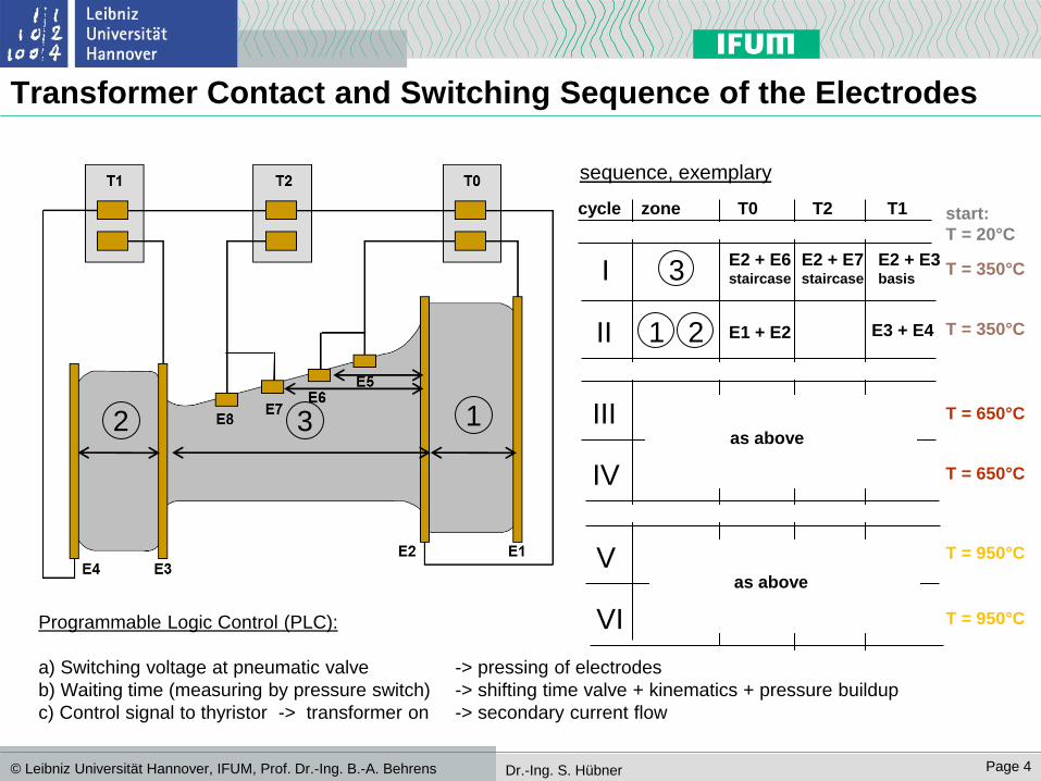
Transformer Contact and Switching Sequence of the Electrodes
2 3 1
zone T0 T2 T1
E2 + E7 staircase
E2 + E3 basis
E2 + E6 staircase
cycle
3
1 2 II
IV
III
I
E1 + E2 E3 + E4
start:
T = 20°C
T = 350°C
as above
VI
V
T = 650°C
as above
T = 950°C
sequence, exemplary
T = 350°C
T = 650°C
T = 950°C Programmable Logic Control (PLC):
a) Switching voltage at pneumatic valve -> pressing of electrodes
b) Waiting time (measuring by pressure switch) -> shifting time valve + kinematics + pressure buildup
c) Control signal to thyristor -> transformer on -> secondary current flow

IFW, Universität Hannover Page 5 © Leibniz Universität Hannover, IFUM, Prof. Dr.-Ing. B.-A. Behrens Dr.-Ing. S. Hübner
Connection Diagram thyristor
power stage
transfor-
mers
electrodes and
blank zones
pyro-
meter controller L1
L2
PC
P0
P1
P2
T0
T1
T2 thyristor-
controller 1
thyristor-
controller 0
thyristor-
controller 2
PLC
R0
R1
profi-
bus
PLC
pneumatic
valves
elektrodes
1-9
profibus-
joint
PC
8 bar
USt,0
L3
R2
Tist,0
Tist,1
Tist,2
RS232-
converter
Tist,0-2
Yist,0-2
Tsoll,0-2
OPC-server
Ymax,0-2
USt,0
USt,2
USt,1
USt,1
USt,2
out-
side
control
middle
IFW, Universität Hannover Page 6 © Leibniz Universität Hannover, IFUM, Prof. Dr.-Ing. B.-A. Behrens Dr.-Ing. S. Hübner
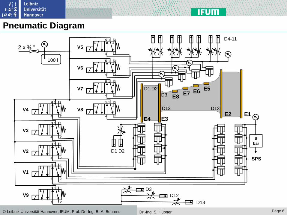
Pneumatic Diagram
E1 E2 E3 E4
E5 E6 E7
E8
2
1 3
4
5
V5
2
1 3
4
5
V6
2
1 3
4
5
V7
2
1 3
4
5
V8
2
1 3
4
5
V4
2
1 3
4
5
V3
2
1 3
4
5
V2
2
1 3
4
5
V1
8
bar
SPS
2 x ¾ "
100 l
2
1 3
4
5
V9
D3
D12
D13
D3
D13 D12
D1 D2
D4-11
D1 D2
IFW, Universität Hannover Page 7 © Leibniz Universität Hannover, IFUM, Prof. Dr.-Ing. B.-A. Behrens Dr.-Ing. S. Hübner
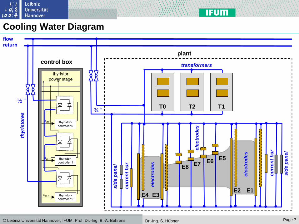
Cooling Water Diagram
flow
return
control box
plant
½ "
¾ "
transformers
ele
ctr
od
es
thy
ris
tore
s
T0 T2 T1
ele
ctr
od
es
ele
ctr
od
es
cu
rre
nt
bar
cu
rre
nt
bar
sid
e p
an
el
E1 E2 E3 E4
E5 E6
E7 E8
sid
e p
an
el
IFW, Universität Hannover Page 8 © Leibniz Universität Hannover, IFUM, Prof. Dr.-Ing. B.-A. Behrens Dr.-Ing. S. Hübner
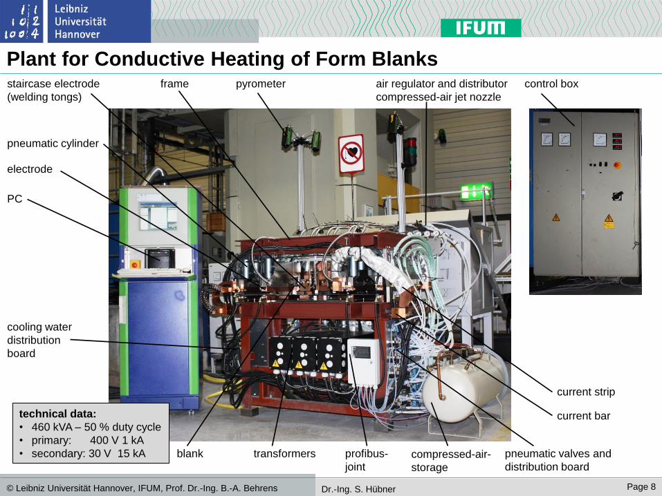
Plant for Conductive Heating of Form Blanks pyrometer
blank
pneumatic cylinder
transformers profibus-
joint
cooling water
distribution
board
pneumatic valves and
distribution board
staircase electrode
(welding tongs)
frame
current strip
current bar
PC
control box
compressed-air-
storage
air regulator and distributor
compressed-air jet nozzle
electrode
technical data:
• 460 kVA – 50 % duty cycle
• primary: 400 V 1 kA
• secondary: 30 V 15 kA

IFW, Universität Hannover Page 9 © Leibniz Universität Hannover, IFUM, Prof. Dr.-Ing. B.-A. Behrens Dr.-Ing. S. Hübner
Heating Zone
blank
pneumatic cylinder electrode
thermal insulating blank ceramic deflection barricade
staircase electrode (welding tongs)
current strip
compressed-air jet nozzle
IFW, Universität Hannover Page 10 © Leibniz Universität Hannover, IFUM, Prof. Dr.-Ing. B.-A. Behrens Dr.-Ing. S. Hübner
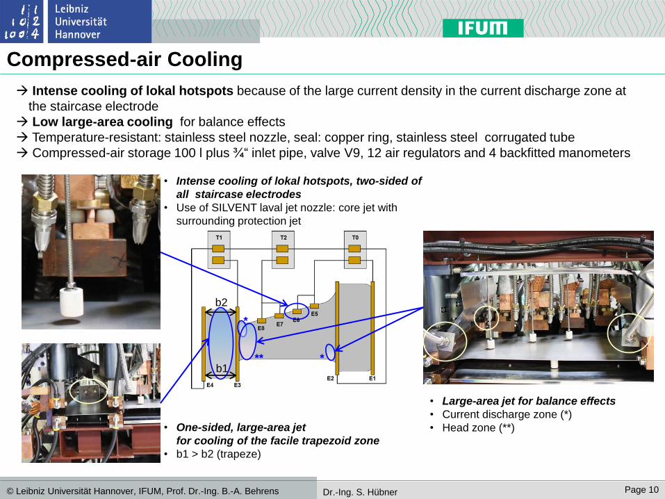
Compressed-air Cooling
Intense cooling of lokal hotspots because of the large current density in the current discharge zone at
the staircase electrode
Low large-area cooling for balance effects
Temperature-resistant: stainless steel nozzle, seal: copper ring, stainless steel corrugated tube
Compressed-air storage 100 l plus ¾“ inlet pipe, valve V9, 12 air regulators and 4 backfitted manometers
• Intense cooling of lokal hotspots, two-sided of
all staircase electrodes
• Use of SILVENT laval jet nozzle: core jet with
surrounding protection jet
• Large-area jet for balance effects
• Current discharge zone (*)
• Head zone (**)
b1
b2
• One-sided, large-area jet
for cooling of the facile trapezoid zone
• b1 > b2 (trapeze)
*
*
**
IFW, Universität Hannover Page 11 © Leibniz Universität Hannover, IFUM, Prof. Dr.-Ing. B.-A. Behrens Dr.-Ing. S. Hübner
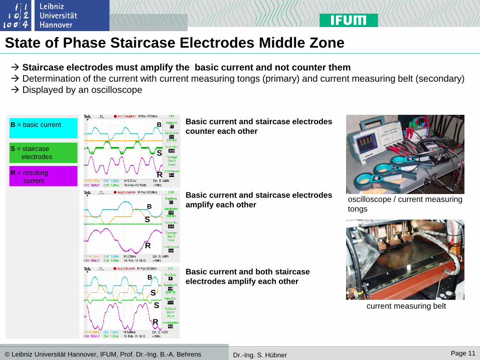
State of Phase Staircase Electrodes Middle Zone
Staircase electrodes must amplify the basic current and not counter them
Determination of the current with current measuring tongs (primary) and current measuring belt (secondary)
Displayed by an oscilloscope
oscilloscope / current measuring
tongs
current measuring belt
B = basic current
S = staircase
electrodes
R = resulting
current
B
S
R
B
S
R
B
S
R
S
Basic current and staircase electrodes
counter each other
Basic current and staircase electrodes
amplify each other
Basic current and both staircase
electrodes amplify each other
IFW, Universität Hannover Page 12 © Leibniz Universität Hannover, IFUM, Prof. Dr.-Ing. B.-A. Behrens Dr.-Ing. S. Hübner
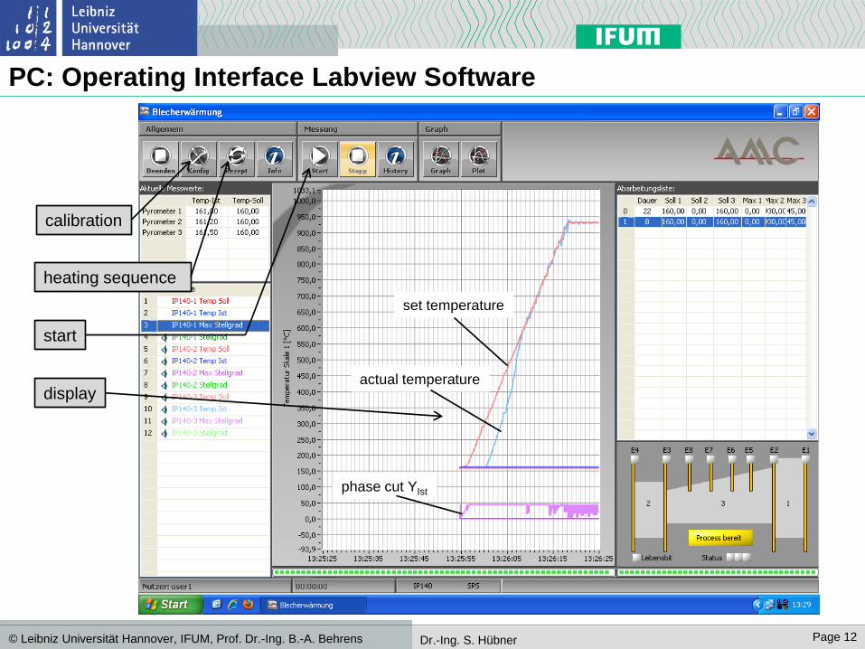
PC: Operating Interface Labview Software
calibration
heating sequence
start
display
set temperature
actual temperature
phase cut YIst
IFW, Universität Hannover Page 13 © Leibniz Universität Hannover, IFUM, Prof. Dr.-Ing. B.-A. Behrens Dr.-Ing. S. Hübner
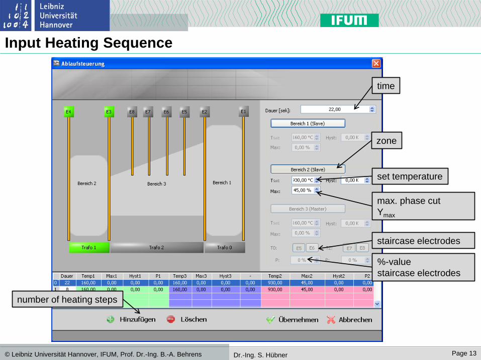
Input Heating Sequence
number of heating steps
zone
time
max. phase cut
Ymax
set temperature
staircase electrodes
%-value
staircase electrodes
IFW, Universität Hannover Page 14 © Leibniz Universität Hannover, IFUM, Prof. Dr.-Ing. B.-A. Behrens Dr.-Ing. S. Hübner
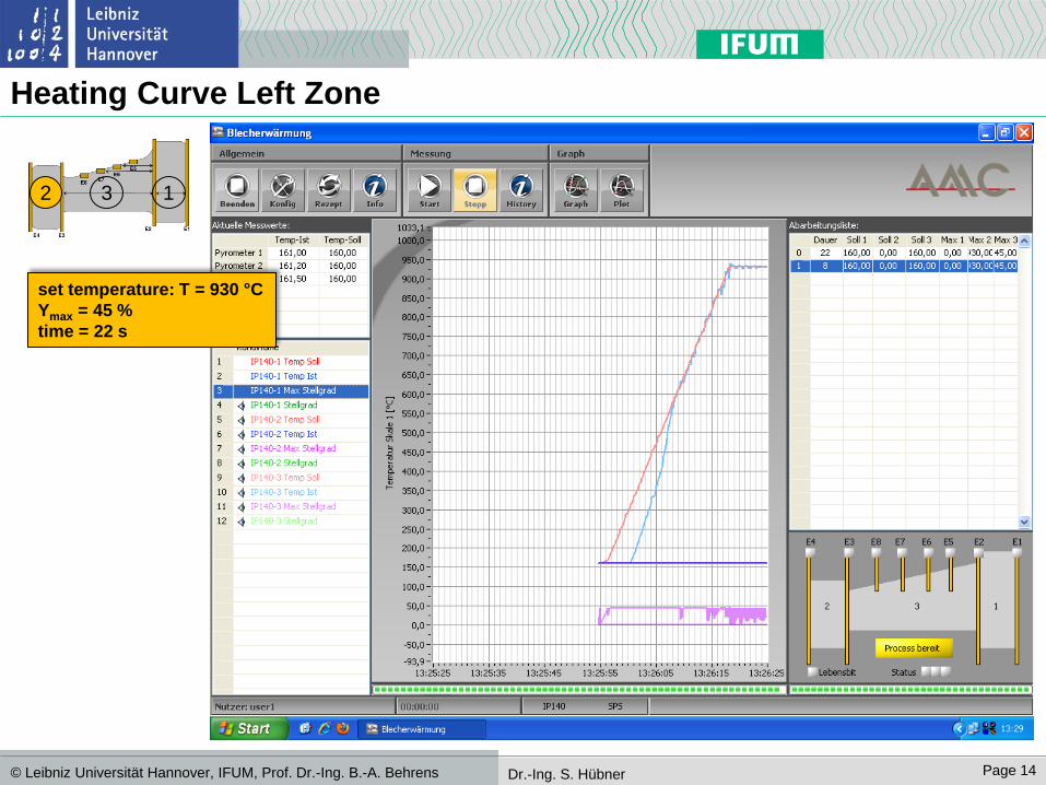
Heating Curve Left Zone
2 3 1
set temperature: T = 930 °C
Ymax = 45 %
time = 22 s
IFW, Universität Hannover Page 15 © Leibniz Universität Hannover, IFUM, Prof. Dr.-Ing. B.-A. Behrens Dr.-Ing. S. Hübner
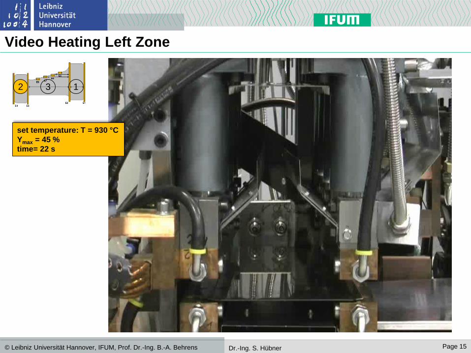
Video Heating Left Zone
2 3 1
set temperature: T = 930 °C
Ymax = 45 %
time= 22 s

IFW, Universität Hannover Page 16 © Leibniz Universität Hannover, IFUM, Prof. Dr.-Ing. B.-A. Behrens Dr.-Ing. S. Hübner
Heating Curve Right Zone
2 3 1
set temperature: T = 930 °C
Ymax = 70 %
time= 45 s
IFW, Universität Hannover Page 17 © Leibniz Universität Hannover, IFUM, Prof. Dr.-Ing. B.-A. Behrens Dr.-Ing. S. Hübner
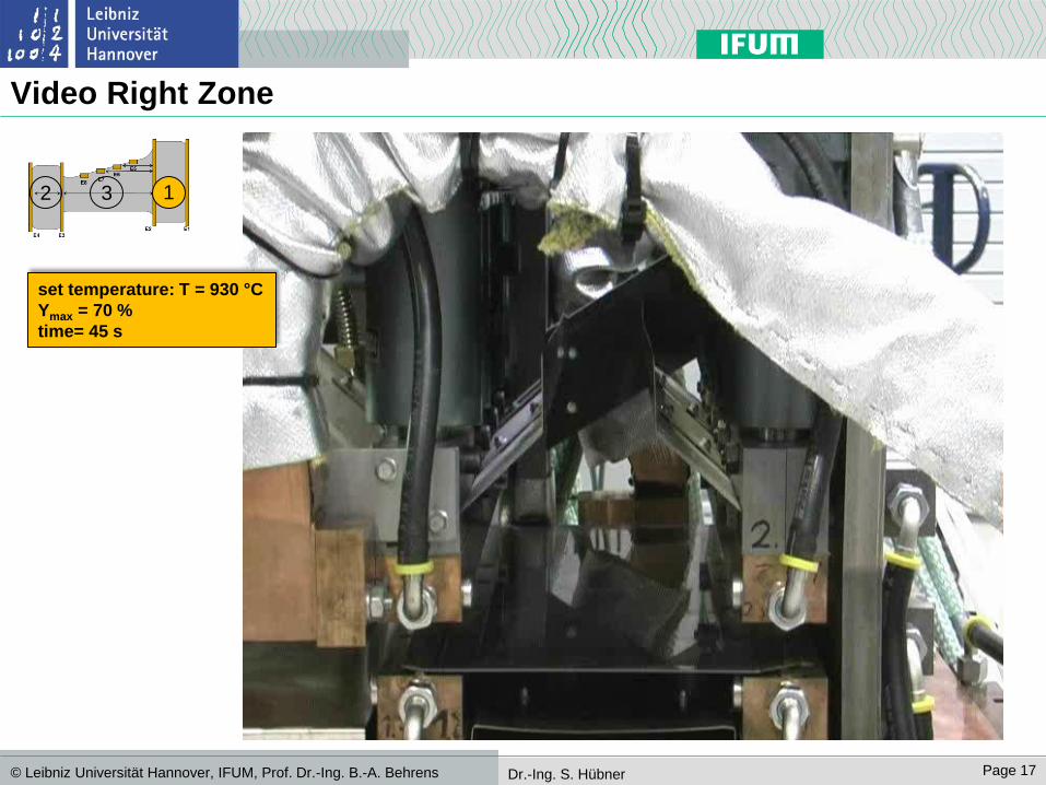
Video Right Zone
2 3 1
set temperature: T = 930 °C
Ymax = 70 %
time= 45 s
IFW, Universität Hannover Page 18 © Leibniz Universität Hannover, IFUM, Prof. Dr.-Ing. B.-A. Behrens Dr.-Ing. S. Hübner
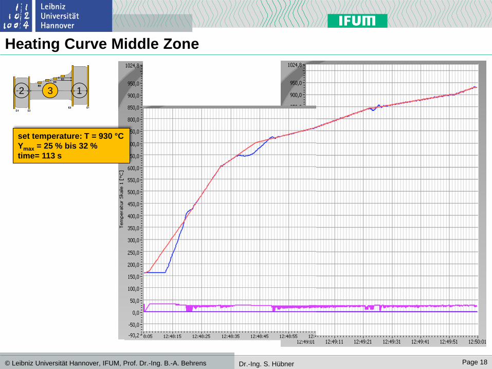
Heating Curve Middle Zone
2 3 1
set temperature: T = 930 °C
Ymax = 25 % bis 32 %
time= 113 s
IFW, Universität Hannover Page 19 © Leibniz Universität Hannover, IFUM, Prof. Dr.-Ing. B.-A. Behrens Dr.-Ing. S. Hübner
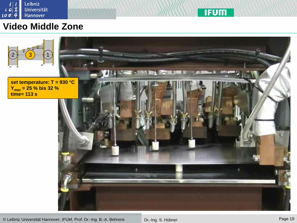
Video Middle Zone
2 3 1
set temperature: T = 930 °C
Ymax = 25 % bis 32 %
time= 113 s

IFW, Universität Hannover Page 20 © Leibniz Universität Hannover, IFUM, Prof. Dr.-Ing. B.-A. Behrens Dr.-Ing. S. Hübner
Heating Experiments
2 3 1
IFW, Universität Hannover Page 21 © Leibniz Universität Hannover, IFUM, Prof. Dr.-Ing. B.-A. Behrens Dr.-Ing. S. Hübner
Summary and Outlook
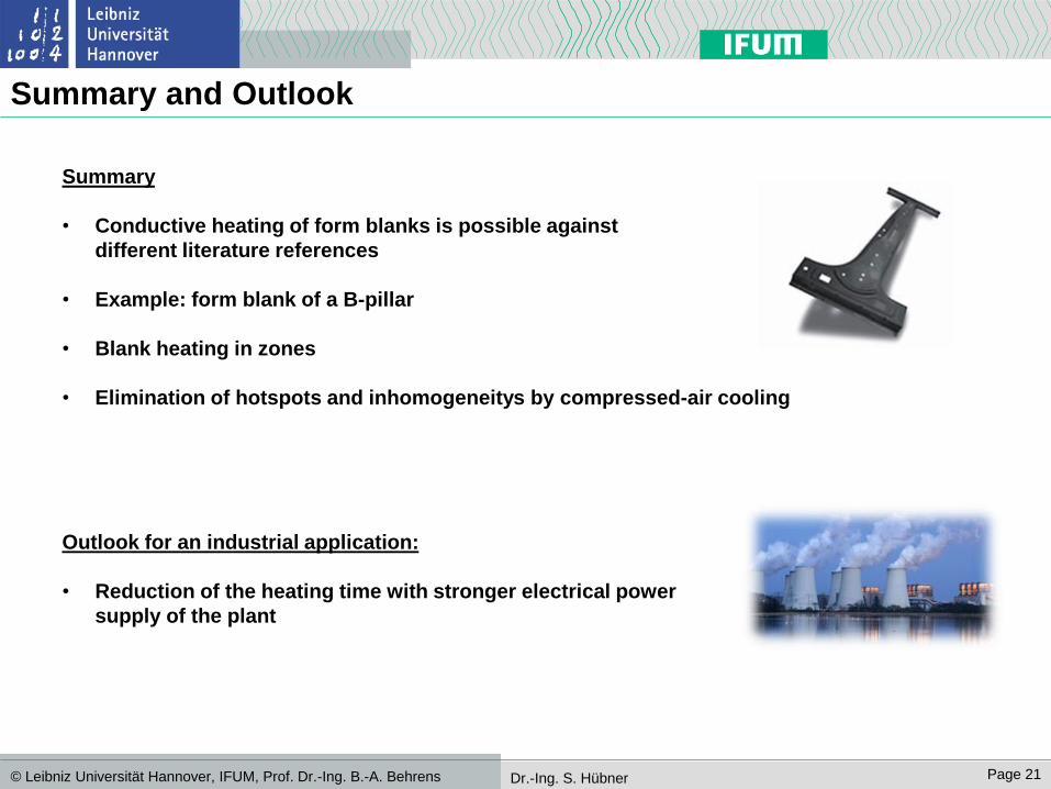
Summary
• Conductive heating of form blanks is possible against
different literature references
• Example: form blank of a B-pillar
• Blank heating in zones
• Elimination of hotspots and inhomogeneitys by compressed-air cooling
Outlook for an industrial application:
• Reduction of the heating time with stronger electrical power
supply of the plant
IFW, Universität Hannover Page 22 © Leibniz Universität Hannover, IFUM, Prof. Dr.-Ing. B.-A. Behrens Dr.-Ing. S. Hübner
Thank you for your attention!
Thanks also goes to the AiF and the EFB for founding the IGF-Project 16248 N.


![ACT-Einführungsworkshop · – Villatte, Villatte, & Hayes (2016). Mastering the Clinical Conversation: Language as Intervention. New York: Guilford Press [va. Kapitel 3 und 6] –](https://static.fdokument.com/doc/165x107/5f677af1f26e7701fe2fa2c5/act-einfhrungsworkshop-a-villatte-villatte-hayes-2016-mastering-the.jpg)