Niederdruck Low pressure - hidraulika.huhidraulika.hu/files/eckstein_niederdruck_katalog.pdf · 3...
73
EN 4/12 Eckstein GmbH D - 65582 Diez Werner-von-Siemens-Str. 3 tel.: +49 (0) 6432 9349 0 fax: +49 (0) 6432 9349 99 e-mail: [email protected] web: www.eckstein.de Niederdruck Low pressure Fluid Technology
Transcript of Niederdruck Low pressure - hidraulika.huhidraulika.hu/files/eckstein_niederdruck_katalog.pdf · 3...

EN 4/12
Eckstein GmbHD - 65582 Diez Werner-von-Siemens-Str. 3 tel.: +49 (0) 6432 9349 0 fax: +49 (0) 6432 9349 99e-mail: [email protected] web: www.eckstein.de
Niederdruck Low pressure
Fluid Technology


3
Inhaltsverzeichnis Table of content
sf
EN 412.01 DE
Bezeichnung
Seite Description Page
Bördelgerät 61 Angle joints 59 Bremsleitung 60 Assortments 63-68 Dichtungen 44-46 Banjo nipple 26 Doppelstutzen 38 Blow guns 39 Druckluft-Kupplungen 41-43 Brake tube 60 Gabelgelenke 58 Brass fittings 30-31 Hülsen 20-21 Central lubrication 54-56 Kabelbinder 71 Die sets 6 Klauenkupplung 49 Drain plugs 29 Lötnippel 28 Elbow banjo 23 Luftpistolen 39 Flaring tool 61 Manometer 39 Gaskets 44-46 Messingarmaturen 30-31 Gauges 39 Muffen 37 Grease nipple 57 Ölablassventil 47 Hose nipple 22 PA-Rohr 32 Hose 8-19 Pressbacken 6 Hose clamps 50-51 Ringgewindestück 26-27 Hose connectors 52-53 Ringnippel 26 Hose crimper 4-5 Rohrbögen 23 Maintenance unit 40 Rohrschellen 51 Oil drain valve 47 Rohrstutzen 25 Pipe clamps 51 Schalldämpfer 40 Pipe nipple 25 Schlauch Plug connector 34-36 -Gasschlauch 15 Polyamide tube 32 -Kraftstoffschlauch 8-11 Quick connect coupling 41-43 -Kühlerschlauch 16-19 Ring connection piece 26-27 -Luftschlauch 12 Silencer 40 -PVC-Schlauch 14 Sleeves 20-21 -Wasserschlauch 13 Sockets 37 Schlauchnippel 22 Solding nipple 28 Schlauchpressen 4-5 Straight studs 38 Schlauchschellen 50-51 Tools 70-71 Schlauchverbinder 52-53 Water coupling 48 Schmiernippel 57 Yokes 58 Sortimente 63-68 Steckverbinder 34-36 Verschlussschrauben 29 Verschlussstopfen 68-69 Wartungseinheit 40 Wasserkupplung 48 Werkzeug 70-71 Winkelgelenke 59 Zentralschmierung 54-56

4
Schlauchpressen Hose crimper
sf
EN 412.02 DE
Handhebel-Schlauchpresse Typ UPS 1 / Hose press Type UPS 1
6-Punkt-Pressung 6 points pressing Arbeitsbereich: DN 1-16 Working Range: DN 1-16 Hülsen ID max. 28 mm Sleeve ID max. 28 mm Inkl. 2 Backensätze: DN 3-8 incl.2 dies Sets: DN 3-8 DN 10-16 DN 10-16 Maße: 400x600x120 Dimensions: 400x600x120 Gewicht: ca. 18 kg Weight: 18 kg
Art.-Nr. 100.000 Pressbackensätze Art.-Nr. Art.N°
Bezeichnung Description
für Eckstein-Hülsen ID (mm)
100.002 DN 3-8 8 - 17
100.003 DN 10-16 18 - 28
100.008 Rohling
-
Handhebel-Schlauchpresse Typ UPS 2 / Hose press Type UPS 2 6-Punkt-Pressung 6 points Pressing Arbeitsbereich: DN 20-25 Working Range: DN 20-25 Hülsen ID max. 38 mm Sleeve ID max. 38 mm Inkl. 2 Backensätze: DN 20 incl.2 dies Sets: DN 20 DN 25 DN 25 Maße: 400x750x120 Dimensions: 400x750x120 Gewicht: ca. 18 kg Weight: 18 kg Art.-Nr. 100.100 Pressbackensätze Art.-Nr. Art.N°
Bezeichnung Description
für Eckstein-Hülsen ID (mm)
100.102 DN 20 30 - 34
100.103 DN 25 32 - 38
100.008 Rohling/ Blank -
Handhebel-Schlauchpresse Typ UPS 3 / Hose press Type UPS 3 8-Punkt-Pressung 8 points Pressing Arbeitsbereich: DN 1-16 Working Range: DN 1-16 Hülsen ID max. 28 mm Sleeve ID max. 28 mm Inkl. 2 Backensätze: DN 3-8 incl.2 dies Sets: DN 3-8 DN 10-16 DN 10-16 Maße: 400x750x120 Dimensions: 400x750x120 Gewicht: ca. 18 k g Weight: 18 kg
Art.-Nr. 100.200
Pressbackensätze Art.-Nr. Art.N°
Bezeichnung Description
für Eckstein-Hülsen ID (mm)
100.202 DN 3-8 8 - 17
100.203 DN 10-16 18 - 28
100.205 Rohling
-
Standfuß für Schlauchpressen Typ UPS Der Standfuß ermöglicht ein sicheres, kraftsparendes Verpressen in optimaler Arbeitshöhe und ermöglicht einen montagefreien Wechsel beim Einsatz von mehreren Maschinen vom Typ UPS.
Stand for hose press type UPS The machine stand provides a save and easy crimping in ideal working position and provides tool-free changing of machines, if more than one UPS is in use. Maße / Dimension: 270x685x160
Gewicht / Weight: 9 kg Art.-Nr. 100.250
Weitere Pressbacken finden Sie auf Seite 72 / further Die-sets on page 72
5
Schlauchpressen Hose crimper
sf
EN 412.02 DE
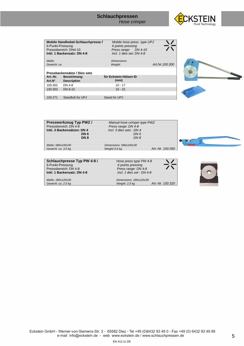
Mobile Handhebel-Schlauchpresse / Mobile hose press type UPJ 6-Punkt-Pressung 6 points pressing Presssbereich: DN4-10 Press range: DN 4-10 Inkl. 1 Backensatz: DN 4-8 Incl. 1 dies set: DN 4-8 Maße: Dimensions:
Gewicht: ca Weight: Art.Nr.100.300
Pressbackensätze / Dies sets Art.-Nr.
Art.N°
Bezeichnung
Description
für Eckstein-Hülsen ID (mm)
100.302 DN 4-8 10 - 17
100.303 DN 8-10 16 - 22
100.271 Standfuß für UPJ Stand for UPJ
Presswerkzeug Typ PWZ / Manual hose crimper type PWZ Presssbereich: DN 4-8 Press range: DN 4-8 Inkl. 3 Backensätzen: DN 4 Incl. 3 dies sets : DN 4 DN 6 DN 6 DN 8 DN 8 Maße: 580x100x30 Dimensions: 580x100x30
Gewicht: ca. 3,5 kg Weight:3,5 kg Art.-Nr. 100.050
Schlauchpresse Typ PW 4-8 / Hose press type PW 4-8
6-Punkt-Pressung 6 points pressing Presssbereich: DN 4-8 Press range: DN 4-8 Inkl. 1 Backensatz: DN 4-8 Incl. 1 dies set : DN 4-8 Maße: 180x120x30 Dimensions: 180x120x30
Gewicht: ca. 2,5 kg Weight: 2,5 kg Art.-Nr. 100.320

6 EN 412.02 DE
Schlauchpressen Hose crimper
sf
Die neu entwickelte Produktionsschlauchpresse vom Typ UPP eignet sich perfekt für die Serienfertigung von Niederdruckschlauchleitungen und bietet gleich mehrere Innovationen:
Steuerbare Prozesszeit & Minimaldruckeinstellung für zuverlässige Wiederholgenauigkeit
Vergrößerter Durchlass (90mm) für große Nennweiten (bis DN 50 / 2“) und komplexe Bögen
Reduzierte Werkzeugbreite und Deckelstärke für komplexe Verpressungen
Mobiles Bedienpanel und neue Steuerung ermöglichen wahlweise horizontales von rechts oder links und vertikales Pressen
Zusätzliche Einstell- oder Abfrageoptionen sind über die SPS-Steuerung möglich
Lieferbare Ausführungen:
Art. Nr. 100.760 UPP 1 – 6 Pressbacken: empfohlen bis DN 32
Art. Nr. 100.761 UPP 2 – 8 Pressbacken: empfohlen bis DN 50
Pressbacken können nach Kundenwusch gefertigt und somit die Pressung optimiert werden.
Weitere Zubehörteile, wie kundenspezifische Endanschläge, können kurzfristig gefertigt werden.
Neue Serien-Schlauchpressen Typ UPP / New production hose crimper type UPP :

7
Schlauchpressen Hose crimper
sf
EN 412.02 DE
Technische Daten: Öffnung 90 mm Max. Hub 25 mm Max. Durchlass Backenendpressmaß + 50 mm Nennweitenempfehlung UPP 1 – 6 Pressbacken DN 1 bis DN 32 UPP 3 – 8 Pressbacken DN 1 bis DN 50 Abmessungen (LxBxH)
Presswerkzeug 1.000 x 220 x 530 mm
Schaltschrank 500 x 500 x 210 mm
Bedienpanel 270 x 75 x 95 mm Gewicht inkl. Transportverpackung 160 kg
Gesamtgewicht netto 122 kg
Presswerkzeug 98 kg
Schaltschrank + Panel 24 kg Spannung 220 V Arbeitsdruck 4 - 8 bar
Zusätzliche Optionen: Individuelle Backensätze Komplexe Pressmuster Prägebacken Manuelle Endanschläge Endanschlag mit Positionsabfrage (Abb. 3 +4) Positionsabfrage Endpresspunkt Bestellnummern: 100.760 UPP 1 – 6 Pressbacken 100.761 UPP 3 – 8 Pressbacken Gerne beraten wir Sie für Ihre spezifische Aufgabenstellung und bieten Ihnen Tests / Musterpressungen an Hand Ihrer Materialmuster an.

8
Kraftstoffschlauch Gasoline hose
sf
EN 412.01 DE
Kraftstoffschlauch DIN 73379(1982/3) Typ PZ / Oil or Gasoline Hose DIN 73379 Type PZ
Schlauch aus synthetischem Gummi mit einer Umflechtung aus verzinktem Stahldraht. 1 Kennfaden (schwarz). Temperaturbereich: - 35°C bis + 80°C Synthetic rubber inner tube with steel wire braided cover. 1 marking threat (black). Temperature range: -35°C up to +80°C. Art.Nr Art.N°
Bezeichnung Description
ID (mm)
AD (mm)
Betriebsdruck (bar)
Berstdruck (bar)
101.005 PZ 5 4,5 9,5 20 60 101.006 PZ 6 5,5 10,5 20 60 101.008 PZ 8 7,5 12,5 15 50 101.010 PZ 10 9,5 14,0 15 50 101.012 PZ 12 11,5 18,0 15 50 101.015 PZ 15 14,5 22,0 15 50 101.018 PZ 18 17,0 25,0 15 50 101.020 PZ 20 22,0 30,0 10 30 101.025 PZ 25 25,0 33,0 10 25
Kraftstoffschlauch DIN 73379 Typ PZK / Oil or Gasoline Hose DIN 73379 Type PZK
Schlauch aus synthetischem Gummi mit einer Umflechtung aus verzinktem Stahldraht. Ohne Kennfaden. Temperaturbereich: - 35°C bis + 80°C Synthetic rubber inner tube with steel wire braided cover. Without marking threat. Temperature range: -35°C up to +80°C. Art.Nr Art.N°
Bezeichnung Description
ID (mm)
AD (mm)
Betriebsdruck (bar)
Berstdruck (bar)
101.026 PZK 6 5,5 10,5 20 60 101.028 PZK 8 7,5 12,5 15 50 101.030 PZK 10 9,0 14,0 15 50 101.032 PZK 12 11,5 18,0 15 50 101.035 PZK 15 14,5 22,0 15 50
Kraftstoffschlauch DIN 73379 Typ VA-PZ / Oil or Gasoline Hose DIN 73379 Type VA-PZ
Schlauch aus synthetischem Gummi mit einer Umflechtung aus rostfreiem Draht. Ohne Kennfaden. Temperaturbereich: - 35°C bis + 80°C Synthetic rubber inner tube with stainless steel wire braided cover. Without marking threat. Temperature range: -35°C up to +80°C. Art.Nr Art.N°
Bezeichnung Description
ID (mm)
AD (mm)
Betriebsdruck (bar)
Berstdruck (bar)
101.356 VA-PZ 6 5,5 10,5 20 60 101.358 VA-PZ 8 7,5 12,5 15 50 101.360 VA-PZ 10 9,0 15,0 15 50 101.362 VA-PZ 12 11,5 18,0 15 50 101.364 VA-PZ 15 14,5 22,0 15 50 101.365 VA-PZ 18 17,5 24,5 15 50 101.368 VA-PZ 20 19,0 29,0 10 30 101.370 VA-PZ 25 25,0 33,0 10 25
Ölbrennerschlauch EN 6806 Typ PZ-H Schlauch aus synthetischem Gummi mit einer Umflechtung aus verzinktem Stahldraht. 1 Kennfaden (grün). Temperaturbereich: - 35°C bis + 80°C Synthetic rubber inner tube with steel wire braided cover. 1 marking threat (green). Temperature range: -35°C up to +80°C. Art.Nr Art.N°
Bezeichnung Description
ID (mm)
AD (mm)
Betriebsdruck (bar)
Berstdruck (bar)
101.080 PZ-H 5 4,5 9,5 20 60 101.081 PZ-H 6 5,5 10,5 20 60 101.082 PZ-H 8 7,5 12,5 15 50 101.083 PZ-H 10 9,5 14,0 15 50 101.084 PZ-H 12 11,5 18,0 15 50 101.086 PZ-H 15 14,5 22,0 15 50 101.087 PZ-H 18 17,0 25,0 15 50 101.088 PZ-H 20 22,0 30,0 10 30 101.089 PZ-H 25 25,0 33,0 10 25
Weitere Kennfaden-Farben auf Anfrage lieferbar

9
Kraftstoffschlauch Gasoline hose
sf
EN 412.01 DE
Kraftstoffschlauch DIN 73379-B Typ PZA / Oil or Gasoline Hose DIN 73379-B Type PZA
Schlauch aus synthetischem Gummi mit einer Textilumflechtung. Temperaturbereich: - 35°C bis + 80°C. Rolle=20mtr Synthetic rubber inner tube with textile braided cover. Temperature range: -35°C up to +80°C.Coil=20m Art.Nr Art.N°
Bezeichnung Description
ID (mm)
AD (mm)
Betriebsdruck (bar)
Berstdruck (bar)
101.303 PZA 3 3,2 7,0 10 40 101.304 PZA 5 4,5 9,5 10 40 101.306 PZA 6 5,5 10,5 10 40 101.308 PZA 8 7,5 12,5 10 40 101.310 PZA 10 9,5 15,0 10 40 101.312 PZA 12 11,5 17,0 10 40 101.315 PZA 15 15,0 22,0 10 40 101.318 PZA 18 18,0 26,0 10 40
Kraftstoffschlauch DIN 73379 Typ PZC / Oil or Gasoline Hose DIN 73379 Type PZC
Schlauch aus synthetischem Gummi, ein Textilgeflecht und eine Umflechtung aus verzinktem Stahldraht. 1 Kennfaden (schwarz). Temperaturbereich: - 35°C bis + 80°C. Synthetic rubber inner tube, single textile braid reinforcement and steel wire braided cover. 1 marking threat (black).Temperature range: -35°C up to +80°C. Art.Nr Art.N°
Bezeichnung Description
ID (mm)
AD (mm)
Betriebsdruck (bar)
Berstdruck (bar)
101.106 PZC 6 5,5 11,5 30 60 101.108 PZC 8 7,5 13,5 30 60 101.110 PZC 10 9,0 15,0 25 45 101.112 PZC 12 11,5 18,5 25 45 101.115 PZC 15 15,0 23,0 25 45 101.118 PZC 18 17,5 26,0 25 45
Kraftstoffschlauch DIN 73379-2A Typ PZG / Oil or Gasoline Hose DIN 73379-2A Type PZG
Kraftstoffschlauch aus synthetischem Gummi mit einer Textileinlage. Außen glatt schwarz (CR). Temperaturbereich: - 40°C bis + 90°C. Synthetic rubber hose with one textile inlay. Outside black and smooth. Temperature range: -40°C up to +90°C. Art.Nr Art.N°
Bezeichnung Description
ID (mm)
AD (mm)
Betriebsdruck (bar)
Berstdruck (bar)
101.503 PZG 3,2 3,2 8,0 10 30 101.504 PZG 4 3,5 9,5 10 30 101.505 PZG 5 4,5 10,5 10 30 101.506 PZG 6 5,5 11,5 10 30 101.508 PZG 8 7,5 13,5 10 30 101.510 PZG 10 9,3 15,3 10 30 101.512 PZG 12 11,5 18,5 10 30
Kraftstoffschlauch Typ RME / Oil or Gasoline Hose Type RME
Biodiesel- / Benzinschlauch aus synthetischem Gummi mit einer Textileinlage. Außen glatt schwarz (CR). Temperaturbereich: - 30°C bis + 100°C. Synthetic rubber hose with one textile inlay. Outside black and smooth. Temperature range: -30°C up to +100°C. Coil=20 m Art.Nr Art.N°
Bezeichnung Description
ID (mm)
AD (mm)
Betriebsdruck (bar)
Berstdruck (bar)
101.170 RME 6 6 12 20 60 101.172 RME 8 8 14 20 60 101.174 RME 10 10 17 20 60 101.177 RME 13 13 20 20 60 101.180 RME 16 16 23 20 60 101.183 RME 19 19 28 20 60 101.186 RME 25 25 36 20 60
Hochtemperatur-Kraftstoffschlauch Typ PZT Schlauch aus synthetischem Gummi mit einer Einlage aus Edelstahldraht und einer zusätzlichen Umflechtung aus Edelstahldraht. Temperaturbereich: -40°C bis +150°C Synthetic rubber hose with one stainless steel wire inlay, single stainless steel wire braided cover. Temperature range: -40°C up to +150°C. Art.Nr Art.N°
Bezeichnung Description
ID (mm)
AD (mm)
Betriebsdruck (bar)
101.224 PZT 6 5,6 11,2 100 101.223 PZT 8 8,6 14,0 100 101.222 PZT 12 11,2 16,3 100 101.220 PZT 15 14,2 20,3 85 101.219 PZT 18 17,5 23,9 70 101.218 PZT 22 22,4 29,5 50

10
Kraftstoffschlauch Gasoline hose
sf
EN 412.01 DE
Kraftstoffschlauch Typ PZSG (OLN) / Oil or Gasoline Hose Type PZSG (OLN)
Schlauchseele aus synthetischem Gummi, eine Textileinlage (ab DN25 zwei Textileinlagen) und eine abriebfeste Gummi-außenschicht (CR), ozon- und lichtrißbeständig. Temperaturbereich: Hydr.Öl (nach DIN 51524) -40° bis +100°C, Diesel bis +40°C. Synthetic rubber inner tube, one textile braid reinforcement and a synthetic rubber cover with low rub down. Ozone and light resistant. Temperature range: hydr.oil (according DIN 51524) -40°C up to +100°C, diesel up to +40°C. Art.Nr Art.N°
Bezeichnung Description
ID (mm)
AD (mm)
Betriebsdruck (bar)
Berstdruck (bar)
101.402 PZSG 3 – FPM/ECO 3,2 3,2 9,0 25 80 101.405 PZSG 4 4,0 10,0 25 80 101.406 PZSG 6 6,0 12,0 25 80 101.408 PZSG 8 8,0 14,0 25 80 101.410 PZSG 10 9,0 15,0 25 80 101.412 PZSG 12 11,0 18,0 20 60 101.413 PZSG 15 15,0 23,0 20 60 101.420 PZSG 20 20,0 30,0 12 40
Kraftstoffschlauch Typ PZSGH (OLNH) / Oil or Gasoline Hose Type PZSGH (OLNH)
Schlauchseele aus synthetischem Gummi, eine Textileinlage (ab DN25 zwei Textileinlagen) und eine abriebfeste Gummi-außenschicht (CR), ozon- und lichtrißbeständig. Temperaturbereich: Hydr.öl (nach DIN 51524) - 40°C bis + 120°C, Diesel bis +80°C. Synthetic rubber inner tube, one textile braid reinforcement and a synthetic rubber cover with low rub down. Ozone and light resistant. Temperature range: hydr.oil (according DIN 51524) -40°C up to +120°C, diesel up to +80°C. Art.Nr Art.N°
Bezeichnung Description
ID (mm)
AD (mm)
Betriebsdruck (bar)
Berstdruck (bar)
101.426 PZSGH 6 6,0 12,0 30 200 101.428 PZSGH 8 8,0 14,0 30 150 101.430 PZSGH 10 9,5 15,5 27 140 101.432 PZSGH 12 12,0 19,0 27 160 101.433 PZSGH 13 13,0 22,0 25 120 101.436 PZSGH 16 16,0 25,0 20 110 101.438 PZSGH 20 20,0 30,0 20 100 101.440 PZSGH 25 25,4 35,9 20 100
Kraftstoffschlauch Typ PZSGS (OLNS) / Oil or Gasoline Hose Type PZSGS (OLNS)
Schlauchseele aus synthetischem Gummi, eine Textileinlage (ab DN25 zwei Textileinlagen) und eine abriebfeste Gummi-außenschicht (CR), ozon- und lichtrißbeständig. Temperaturbereich: Hydr.öl (nach DIN 51524) -35°C bis +150°C, Diesel bis +80°C Als Ölkühlerschlauch geeignet. Synthetic rubber inner tube, one textile braid reinforcement and a synthetic rubber cover with low rub down. Ozone and light resistant. Temperature range: hydr.oil (according DIN 51524) -35°C up to +150°C, diesel up to +80°C. Art.Nr Art.N°
Bezeichnung Description
ID (mm)
AD (mm)
Betriebsdruck (bar)
Berstdruck (bar)
101.468 PZSGS 6 6,0 12,0 30 250 101.469 PZSGS 8 8,0 14,0 25 200 101.470 PZSGS 10 10,0 16,0 25 200 101.472 PZSGS 12 12,0 19,0 20 150 101.474 PZSGS 16 16,0 24,0 20 150 101.476 PZSGS 20 20,0 30,0 20 150 101.478 PZSGS 25 25,0 35,5 20 150
Hochtemperatur-Kraftstoffschlauch DIN 73379-3E Typ FPM/ECO High Temperature Gasoline Hose DIN 73379-3E Type FPM/ECO Schlauchseele aus FPM, eine Textileinlage (AR), außen Stoff gemustert. Inner hose in FPM, a textile lining (AR), outside fabric patterned Temperaturbereich / temperature range: -40°C bis/ up to +125°C Art.Nr Art.N°
Bezeichnung Description
ID (mm)
AD (mm)
Betriebsdruck (bar)
101.155 FPM/ECO 6 5,5 11,5 10 101.158 FPM/ECO 8 7,3 13,3 10 101.160 FPM/ECO 10 9,3 15,3 10 101.162 FPM/ECO 12 11,5 17,5 10 101.163 FPM/ECO 15 14,3 21,3 10 101.165 FPM/ECO 18 17,0 24,0 10
11
Kraftstoffschlauch Gasoline hose
sf
EN 412.02 DE
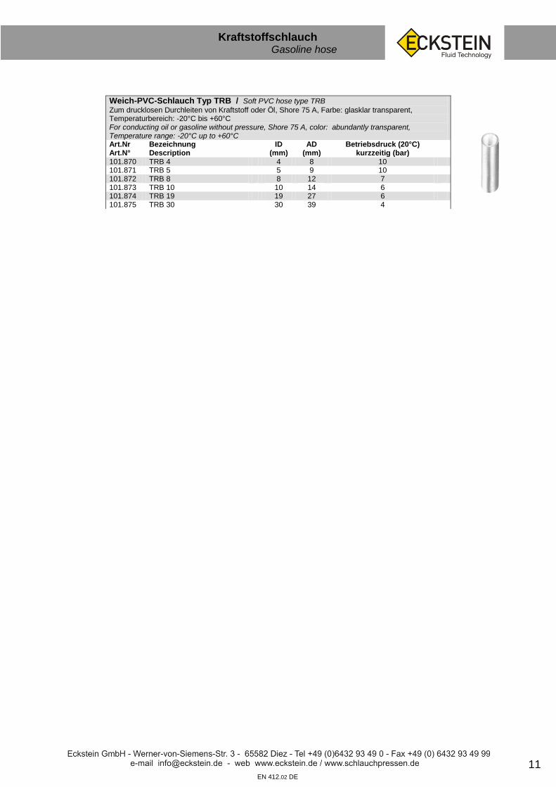
Weich-PVC-Schlauch Typ TRB / Soft PVC hose type TRB
Zum drucklosen Durchleiten von Kraftstoff oder Öl, Shore 75 A, Farbe: glasklar transparent, Temperaturbereich: -20°C bis +60°C For conducting oil or gasoline without pressure, Shore 75 A, color: abundantly transparent, Temperature range: -20°C up to +60°C Art.Nr Art.N°
Bezeichnung Description
ID (mm)
AD (mm)
Betriebsdruck (20°C) kurzzeitig (bar)
101.870 TRB 4 4 8 10 101.871 TRB 5 5 9 10 101.872 TRB 8 8 12 7 101.873 TRB 10 10 14 6 101.874 TRB 19 19 27 6 101.875 TRB 30 30 39 4
12
Luftschlauch Air hose
sf
EN 412.01 DE
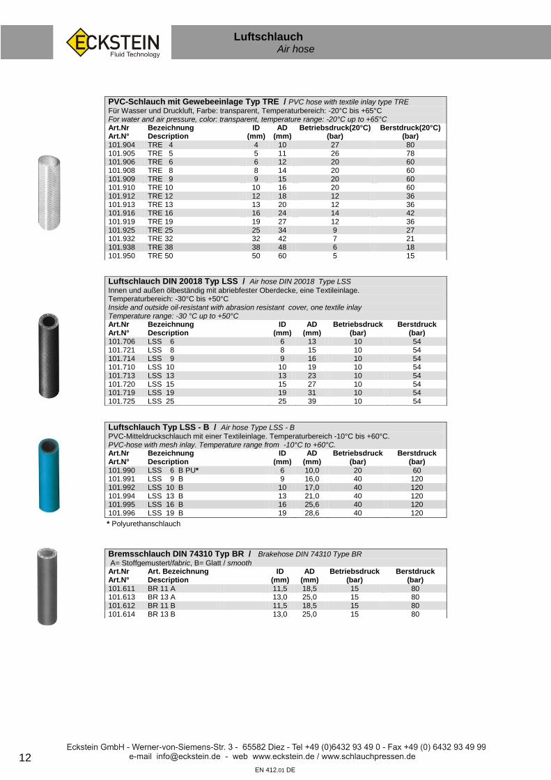
PVC-Schlauch mit Gewebeeinlage Typ TRE / PVC hose with textile inlay type TRE
Für Wasser und Druckluft, Farbe: transparent, Temperaturbereich: -20°C bis +65°C For water and air pressure, color: transparent, temperature range: -20°C up to +65°C Art.Nr Art.N°
Bezeichnung Description
ID (mm)
AD (mm)
Betriebsdruck(20°C) (bar)
Berstdruck(20°C) (bar)
101.904 TRE 4 4 10 27 80 101.905 TRE 5 5 11 26 78 101.906 TRE 6 6 12 20 60 101.908 TRE 8 8 14 20 60 101.909 TRE 9 9 15 20 60 101.910 TRE 10 10 16 20 60 101.912 TRE 12 12 18 12 36 101.913 TRE 13 13 20 12 36 101.916 TRE 16 16 24 14 42 101.919 TRE 19 19 27 12 36 101.925 TRE 25 25 34 9 27 101.932 TRE 32 32 42 7 21 101.938 TRE 38 38 48 6 18 101.950 TRE 50 50 60 5 15
Luftschlauch DIN 20018 Typ LSS / Air hose DIN 20018 Type LSS Innen und außen ölbeständig mit abriebfester Oberdecke, eine Textileinlage. Temperaturbereich: -30°C bis +50°C Inside and outside oil-resistant with abrasion resistant cover, one textile inlay Temperature range: -30 °C up to +50°C Art.Nr Art.N°
Bezeichnung Description
ID (mm)
AD (mm)
Betriebsdruck (bar)
Berstdruck (bar)
101.706 LSS 6 6 13 10 54 101.721 LSS 8 8 15 10 54 101.714 LSS 9 9 16 10 54 101.710 LSS 10 10 19 10 54 101.713 LSS 13 13 23 10 54 101.720 LSS 15 15 27 10 54 101.719 LSS 19 19 31 10 54 101.725 LSS 25 25 39 10 54
Luftschlauch Typ LSS - B / Air hose Type LSS - B
PVC-Mitteldruckschlauch mit einer Textileinlage. Temperaturbereich -10°C bis +60°C. PVC-hose with mesh inlay. Temperature range from -10°C to +60°C. Art.Nr Art.N°
Bezeichnung Description
ID (mm)
AD (mm)
Betriebsdruck (bar)
Berstdruck (bar)
101.990 LSS 6 B PU* 6 10,0 20 60 101.991 LSS 9 B 9 16,0 40 120 101.992 LSS 10 B 10 17,0 40 120 101.994 LSS 13 B 13 21,0 40 120 101.995 LSS 16 B 16 25,6 40 120 101.996 LSS 19 B 19 28,6 40 120
Bremsschlauch DIN 74310 Typ BR / Brakehose DIN 74310 Type BR
A= Stoffgemustert/fabric, B= Glatt / smooth Art.Nr Art.N°
Art. Bezeichnung Description
ID (mm)
AD (mm)
Betriebsdruck (bar)
Berstdruck (bar)
101.611 BR 11 A 11,5 18,5 15 80 101.613 BR 13 A 13,0 25,0 15 80 101.612 BR 11 B 11,5 18,5 15 80 101.614 BR 13 B 13,0 25,0 15 80
* Polyurethanschlauch

13
Wasserschlauch Water hose
sf
EN 412.01 DE
Trink- und Heisswasserschlauch Typ TWS / Drinking and hot water hose type TWS
Schlauchseele aus hochwertigem Butyl-Kautschuk mit einer Umflechtung aus Edelstahldraht. KTW- und DVGW-Zulassung, Betriebstemperatur -30°C bis +100°C (kurzzeitig bis +110°C) Inner hose of high-quality butyl rubber with a braided stainless steel wire. KTW- and DVGW approval, working temperature -30°C up to +100°C(short term up to 110°C) Art.Nr Art.N°
Bezeichnung Description
ID (mm)
AD (mm)
Betriebsdruck (bar)
101.638 TWS 6 5,5 10,0 10 101.639 TWS 8 8,0 11,0 10 101.640 TWS 10 9,5 13,0 10 101.641 TWS 12 12,5 17,0 10 101.647 TWS 15 14,5 21,0 10 101.642 TWS 20 19,0 26,0 10 101.643 TWS 25 25,0 33,5 10 101.644 TWS 32 32,0 41,8 10 101.645 TWS 40 40,0 51,0 10 101.646 TWS 50 50,0 63,0 10
Wasserschlauch Typ TRIX-Rotstrahl / Water hose type TRIX-Rotstrahl
Eine Textileinlage, geeignet für Wasser, wässrige Salzlösungen. Abriebfeste Knickschutzrippen. Farbe: schwarz/rot, Temperaturbereich: -40°C bis +100°C (angegebener Betriebsdruck bei 20°C) One layer of textile, suitable for water or watery salt-solublies. Wear-firm bend protection. Temperature range: -40°C up to +100°C (working pressure at 20°C) Art.Nr Art.N°
Bezeichnung Description
ID (mm)
AD (mm)
Betriebsdruck (bar)
101.628 TRIX 13 13 19 20 101.631 TRIX 16 16 23 20 101.629 TRIX 19 19 27 20 101.630 TRIX 25 25 34 20 101.632 TRIX 32 32 43 15 101.633 TRIX 38 38 50 15 101.634 TRIX 50 50 64 10
Wasserschlauch Typ WS / Water hose Type WS
Mit gekreuzten Polyestereinlagen Farbe: rot/gelb. Temperaturbereich: - 20°C bis + 60°C. With one crossing polyester layer. Color: red. Temperature range: -20°C up to + 60°C Art.Nr Art.N°
Bezeichnung Description
ID (mm)
AD (mm)
Betriebsdruck (bar)
101.623 WS 13 13 19 10 101.624 WS 19 19 27 10 101.625 WS 25 25 34 10
Goldschlange Wasserschlauch Typ GSS / Water hose Type GSS
Hochleistungs EPDM Wasser- und Reinigungsschlauch, Temperaturbereich: -30°C bis +100°C. Außenschicht CR (schwarz). EPDM water and cleaning hose, temperature: -30°C up to +100°C Art.Nr Art.N°
Bezeichnung Description
ID (mm)
AD (mm)
Betriebsdruck (bar)
101.620 GSS 13 13 20,8 30 101.621 GSS 19 19 27,8 25 101.622 GSS 25 25 34,0 20
14
PVC Schlauch PVC hose
sf
EN 412.01 DE
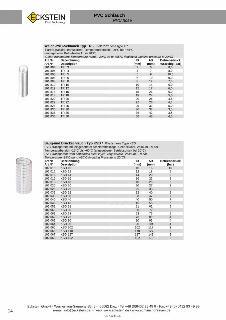
Weich-PVC-Schlauch Typ TR / Soft PVC hose type TR
Farbe: glasklar, transparent. Temperaturbereich: -20°C bis +65°C (angegebener Betriebsdruck bei 20°C). Color: transparent.Temperature range: -20°C up to +65°C (indicated working pressure at 20°C) Art.Nr Art.N°
Bezeichnung Description
ID (mm)
AD (mm)
Betriebsdruck kurzzeitig (bar)
101.803 TR 3 3 5 8,0 101.804 TR 4 4 7 8,0 101.805 TR 5 5 9 10,5 101.806 TR 6 6 10 9,0 101.808 TR 8 8 12 7,0 101.810 TR 10 10 14 6,0 101.812 TR 12 12 17 6,5 101.815 TR 15 15 21 6,0 101.818 TR 18 18 24 5,0 101.820 TR 20 20 26 4,5 101.822 TR 22 22 28 4,3 101.825 TR 25 25 33 5,0 101.830 TR 30 30 38 3,5 101.835 TR 35 35 42 3,5 101.838 TR 38 38 48 4,0
Saug-und Druckschlauch Typ KSD / Plastic hose Type KSD
PVC, transparent, mit eingebetteter Stahldrahteinlage. Sehr flexibel. Vakuum 0,9 bar. Temperaturbereich -15°C bis +60°C (angegebener Betriebsdruck bei 20°C). PVC, transparent, with embedded steel layer. Very flexible. Vacuum 0, 9 bar. Temperature -15°C up to +60°C (working Pressure at 20°C). Art.Nr Art.N°
Bezeichnung Description
ID (mm)
AD (mm)
Betriebsdruck (bar)
102.010 KSD 10 10 16 10 102.012 KSD 12 12 18 9 102.015 KSD 14 14 20 9 102.016 KSD 16 16 22 9 102.018 KSD 18 18 25 8 102.020 KSD 20 20 27 8 102.025 KSD 25 25 33 8 102.032 KSD 32 32 40 8 102.038 KSD 38 38 47 7 102.040 KSD 40 40 50 7 102.045 KSD 45 45 55 6 102.051 KSD 51 51 62 5 102.060 KSD 60 60 72 5 102.061 KSD 63 63 75 5 102.062 KSD 76 76 89 4 102.063 KSD 80 80 93 4 102.064 KSD 90 90 104 4 102.065 KSD 102 102 117 3 102.066 KSD 110 110 127 3 102.067 KSD 127 127 143 3 102.068 KSD 152 152 170 2

15
Wellrohr
sf
EN 412.02 DE
Wellrohr geschlitzt Typ WEL / Material: Polypropylen. Hoher mechanischer Schutz für Kabel und Schläuche. Beständig gegen Laugen, Kraftstoffe, Mineralöle und die meisten Lösungsmittel. Hitzebeständig bis +135°C. Polypropylen, lockable. High mechanical protection for cables and hoses. Fuel-, oil- and lye resistant, also resistant against the most common solvents heatproof up to +135°C Art.Nr Art.N°
Bezeichnung Description
ID (mm)
AD (mm)
min.Biegeradius (mm) min.bend radius (mm)
201.360 WEL 10 SW 8,7 13,6 70 201.361 WEL 14 SW 12,5 18,5 95 201.362 WEL 20 SW 19,5 25,5 130 201.363 WEL 23 SW 24,2 31,0 155 201.364 WEL 37 SW 31,0 41,4 205 201.365 WEL 45 SW 42,7 54,0 190
16
Kühlerschlauch Hose for cooling water
sf
EN 412.01 DE
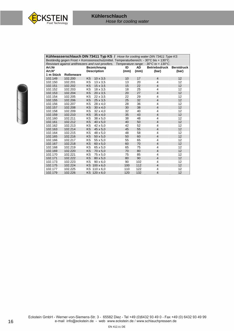
Kühlwasserschlauch DIN 73411 Typ KS / Hose for cooling water DIN 73411 Type KS
Beständig gegen Frost + Korrosionsschutzmittel. Temperaturbereich: - 30°C bis + 130°C. Resistant against antifreezers and rust-proofers. Temperature range: - 30°C to + 130°C. Art.Nr Art.N° 1 m Stück Rollenware
Bezeichnung Description
ID (mm)
AD (mm)
Betriebsdruck (bar)
Berstdruck (bar)
102.149 102.200 KS 10 x 3,5 10 17 4 12 102.150 102.201 KS 13 x 3,5 13 20 4 12 102.151 102.202 KS 15 x 3,5 15 22 4 12 102.152 102.203 KS 18 x 3,5 18 25 4 12 102.153 102.204 KS 20 x 3,5 20 27 4 12 102.154 102.205 KS 22 x 3,5 22 29 4 12 102.155 102.206 KS 25 x 3,5 25 32 4 12 102.156 102.207 KS 28 x 4,0 28 36 4 12 102.157 102.208 KS 30 x 4,0 30 38 4 12 102.158 102.209 KS 32 x 4,0 32 40 4 12 102.159 102.210 KS 35 x 4,0 35 43 4 12 102.160 102.211 KS 38 x 5,0 38 48 4 12 102.161 102.212 KS 40 x 5,0 40 50 4 12 102.162 102.213 KS 42 x 5,0 42 52 4 12 102.163 102.214 KS 45 x 5,0 45 55 4 12 102.164 102.215 KS 48 x 5,0 48 58 4 12 102.165 102.216 KS 50 x 5,0 50 60 4 12 102.166 102.217 KS 55 x 5,0 55 65 4 12 102.167 102.218 KS 60 x 5,0 60 70 4 12 102.168 102.219 KS 65 x 5,0 65 75 4 12 102.169 102.220 KS 70 x 5,0 70 80 4 12 102.170 102.221 KS 75 x 5,0 75 85 4 12 102.171 102.222 KS 80 x 5,0 80 90 4 12 102.173 102.223 KS 90 x 6,0 90 102 4 12 102.175 102.224 KS 100 x 6,0 100 112 4 12 102.177 102.225 KS 110 x 6,0 110 122 4 12 102.179 102.226 KS 120 x 6,0 120 132 4 12

17
Kühlerschlauch Hose for cooling water
sf
EN 412.01 DE
TUBANO Kühlwasserschlauch Typ TUBANO / Hose for cooling water Type TUBANO
Ideal als Formstück-Ersatz. Für Wasser, Säuren und verdünnte Basen. Temperaturbereich: - 40°C bis + 125°C. Lieferung in 1m - Stücken Temperature range: - 40°C to + 125°C. Delivery in 1m - pieces Art.Nr Art.N°
Bezeichnung Description
ID variabel (mm) ID variable (mm)
102.100 TUBANO 20 20,0 – 25 102.101 TUBANO 25 25,0 – 31 102.102 TUBANO 31,5 31,5 – 36 102.103 TUBANO 33,5 33,5 – 38 102.104 TUBANO 37 37,0 – 44 102.105 TUBANO 44 44,0 – 48 102.106 TUBANO 48 48,0 – 55 102.107 TUBANO 55 55,0 – 65 102.108 TUBANO 65 65,0 – 75 102.109 TUBANO 80 80,0 – 90 102.110 TUBANO Set (20-55) 20,0 – 55

18
Kühlerschlauch Hose for cooling water
sf
EN 412.01 DE
Silikon Kühlerschlauch Typ SIL-KS / Silicone cooling hose Type SIL-KS
mit 3 Polyestereinlagen, Temperaturbereich -55 bis + 200°C, geeignet für Frostschutz- und Korrosionsschutzmittel , ozonbeständig, Farbe: blau, Länge: 1 m, Rollenware auf Anfrage with 3 layer of polyester, temperature range -55°C up to +200°C, ozone, freezing fluid and corrosion resistant. Color: Blue, length: 1 m, or rolls available on request. Art.Nr Art.N°
Bezeichnung Description
ID (mm)
AD (mm)
Betriebsdruck (bar)
Berstdruck (bar)
102.308 SIL-KS 8x4,2 8 16,4 11,5 35 102.310 SIL-KS 10x4,2 10 18,4 9,5 29 102.311 SIL-KS 11x4,2 11 19,4 8,5 26 102.313 SIL-KS 13x4,2 13 21,4 8,5 26 102.316 SIL-KS 16x4,2 16 24,4 8,2 22 102.318 SIL-KS 18x4,2 18 26,4 7,5 22 102.319 SIL-KS 19x4,2 19 27,4 6,6 20 102.322 SIL-KS 22x4,2 22 30,4 5,9 18 102.325 SIL-KS 25x4,2 25 33,4 5,6 17 102.328 SIL-KS 28x4,2 28 36,4 5,2 16 102.330 SIL-KS 30x4,2 30 38,4 4,9 15 102.332 SIL-KS 32x4,2 32 40,4 4,9 15 102.335 SIL-KS 35x4,2 35 43,4 4,6 14 102.338 SIL-KS 38x4,2 38 46,4 4,2 13 102.340 SIL-KS 40x4,2 40 48,4 4,0 12 102.341 SIL-KS 42x4,2 42 50,4 3,9 12 102.345 SIL-KS 45x4,2 45 53,4 3,9 12 102.348 SIL-KS 48x4,2 48 56,4 3,6 11 102.350 SIL-KS 50x4,2 50 58,4 3,6 11 102.351 SIL-KS 51x4,2 51 59,4 3,4 10 102.354 SIL-KS 54x4,2 54 62,4 3,3 10 102.355 SIL-KS 55x4,2 55 63,4 3,2 9,7 102.357 SIL-KS 57x4,2 57 65,4 3,1 9,4 102.360 SIL-KS 60x4,2 60 68,4 2,9 9 102.365 SIL-KS 65x4,2 65 73,4 2,8 8,5 102.370 SIL-KS 70x4,2 70 78,4 2,8 8,5 102.375 SIL-KS 75x4,2 75 83,4 2,8 8,5 102.380 SIL-KS 80x4,2 80 88,4 2,6 8

19 EN 412.01 DE
Kühlerschlauch Hose for cooling water
sf
45° Silikon Kühlerschlauch Typ SIL-KS 45° / 45° Silicone cooling hose Type SIL-KS 45°
45° Winkel, Schenkellänge 200 mm / 45° angel, side length 200mm Art.Nr Art.N°
Bezeichnung Description
ID (mm)
AD (mm)
Betriebsdruck (bar)
Berstdruck (bar)
102.510 SIL-KS 45° - 11x4,2 11 19,4 8,5 26 102.513 SIL-KS 45° - 13x4,2 13 21,4 8,5 26 102.516 SIL-KS 45° - 16x4,2 16 24,4 8,2 24 102.518 SIL-KS 45° - 18x4,2 18 26,4 7,5 22 102.519 SIL-KS 45° - 19x4,2 19 27,4 6,6 20 102.522 SIL-KS 45° - 22x4,2 22 30,4 5,9 18 102.525 SIL-KS 45° - 25x4,2 25 33,4 5,6 17 102.528 SIL-KS 45° - 28x4,2 28 36,4 5,2 16 102.530 SIL-KS 45° - 30x4,2 30 38,4 4,9 15 102.532 SIL-KS 45° - 32x4,2 32 40,4 4,9 15 102.535 SIL-KS 45° - 35x4,2 35 43,4 4,6 14 102.538 SIL-KS 45° - 38x4,2 38 46,4 4,2 13 102.540 SIL-KS 45° - 40x4,2 40 48,4 4,0 12 102.541 SIL-KS 45° - 41x4,2 41 49,4 3,9 12 102.545 SIL-KS 45° - 45x4,2 45 53,4 3,9 12 102.548 SIL-KS 45° - 48x4,2 48 56,4 3,9 12 102.550 SIL-KS 45° - 50x4,2 50 58,4 3,6 11 102.551 SIL-KS 45° - 51x4,2 51 59,4 3,3 10 102.554 SIL-KS 45° - 54x4,2 54 62,4 3,3 10 102.560 SIL-KS 45° - 60x4,2 60 68,4 2,9 9 102.563 SIL-KS 45° - 63x4,2 63 71,4 2,8 8,5 102.565 SIL-KS 45° - 65x4,2 65 73,4 2,8 8,5 102.570 SIL-KS 45° - 70x4,2 70 78,4 2,8 8,5 102.575 SIL-KS 45° - 75x4,2 75 83,4 2,8 8,5 102.580 SIL-KS 45° - 80x4,2 80 88,4 2,6 8
90° Silikon Kühlerschlauch Typ SIL-KS 90° / 90° Silicone cooling hose Type SIL-KS 90°
90° Winkel, Schenkellänge 200 mm / 90° angel, side length 200mm Art.Nr Art.N°
Bezeichnung Description
ID (mm)
AD (mm)
Betriebsdruck (bar)
Berstdruck (bar)
102.410 SIL-KS 90° - 11x4,2 11 19,4 8,5 26 102.413 SIL-KS 90° - 13x4,2 13 21,4 8,5 26 102.416 SIL-KS 90° - 16x4,2 16 24,4 8,2 22 102.418 SIL-KS 90° - 18x4,2 18 26,4 7,5 22 102.419 SIL-KS 90° - 19x4,2 19 27,4 6,6 20 102.422 SIL-KS 90° - 22x4,2 22 30,4 5,9 18 102.425 SIL-KS 90° - 25x4,2 25 33,4 5,6 17 102.428 SIL-KS 90° - 28x4,2 28 36,4 5,2 16 102.430 SIL-KS 90° - 30x4,2 30 38,4 4,9 15 102.432 SIL-KS 90° - 32x4,2 32 40,4 4,9 15 102.435 SIL-KS 90° - 35x4,2 35 43,4 4,6 14 102.438 SIL-KS 90° - 38x4,2 38 46,4 4,2 13 102.441 SIL-KS 90° - 40x4,2 40 48,4 3,9 12 102.442 SIL-KS 90° - 41x4,2 41 49,4 3,9 12 102.445 SIL-KS 90° - 45x4,2 45 53,4 3,9 12 102.448 SIL-KS 90° - 48x4,2 48 56,4 3,6 11 102.450 SIL-KS 90° - 50x4,2 50 58,4 3,6 11 102.451 SIL-KS 90° - 51x4,2 51 59,4 3,3 10 102.454 SIL-KS 90° - 54x4,2 54 62,4 3,3 10 102.457 SIL-KS 90° - 57x4,2 57 65,4 3,3 10 102.460 SIL-KS 90° - 60x4,2 60 68,4 2,9 9 102.463 SIL-KS 90° - 63x4,2 63 71,4 2,8 8,5 102.465 SIL-KS 90° - 65x4,2 65 73,4 2,8 8,5 102.470 SIL-KS 90° - 70x4,2 70 78,4 2,8 8,5 102.475 SIL-KS 90° - 75x4,2 75 83,4 2,8 8,5 102.480 SIL-KS 90° - 80x4,2 80 88,4 2,6 8

20
Schlauchhülsen Sleeves
sf
EN 412.01 DE
Schlauchhülsen Typ H / Sleeves Type H
Material: Stahl verzinkt/ Material: steel galvanized
Art.Nr Art.N°
Bezeichnung Description
ID
(mm) Loch-(mm)
bore- (mm)
Länge (mm) Length (mm)
PE unit
104.038 H 3/8 8 5,6 17 100 104.039 H 3/9 9 4,7 17 100 104.040 H 4/9 9 5,7 17 100 104.050 H 5/10 10 6,7 17 100 104.051 H 5/11 11 6,7 17 100 104.060 H 6/11 11 7,7 17 100 104.062 H 6/12 12 7,7 20 100 104.063 H 6/13,5 13,5 7,7 20 100 104.065 H 6/15 15 7,6 20 100 104.064 H 8/12 12 10,0 20 100 104.080 H 8/13,5 13,5 10,2 20 100 104.084 H 8/14 14 10,0 20 100 104.085 H 8/15 15 10,2 20 100 104.105 H 10/15 15 11,8 20 100 104.100 H 10/16 16 11,9 20 100 104.107 H 10/17 17 11,9 21 100 104.118 H 12/18 18 13,9 21 100 104.112 H 12/19 19 14,0 26 100 104.120 H 12/20 20 14,0 26 100 104.156 H 12/21 21 15,7 25 100 104.122 H 12/22 22 15,7 32 100 104.123 H 15/23 23 17,2 32 104.124 H 15/24,5 24,5 17,2 36 104.126 H 18/26,5 26,5 19,7 32 104.128 H 18/28 28 20,7 34 104.130 H 20/30 30 24,2 32 104.132 H 20/32 32 23,7 34 104.133 H 20/33 33 24,2 34 104.136 H 20/34 34 25,9 34 104.134 H 25/32 32 27,9 34 104.137 H 25/34,5 34,5 27,0 35 104.138 H 25/36 36 27,5 35 104.140 H 25/38 38 28,3 35 104.142 H 25/40 40 30,0 40 104.145 H 32/45 45 35,1 37 104.147 H 40/51 51 41,3 43
Schlauchhülsen Typ H / Sleeves Type H
kurze Ausführung, Material: Stahl verzinkt / Short version, Material: steel galvanized
Art.Nr Art.N°
Bezeichnung Description
ID
(mm) Loch-(mm)
bore- (mm)
Länge (mm) Length (mm)
PE unit
104.082 H 8/12,5/15 12,5 9,6 15 100 104.084 H 8/14/20 14 10,2 20 100 104.106 H 10/15/16 15 11,8 16 100 104.121 H 12/20/20 20 13,5 20 100 104.158 H 12/22/20 22 15,4 20 100
Hülsen-Röhrchen Typ HR / Sleeves Type HR
Material: Stahl verzinkt/ Material: steel galvanized Art.Nr Art.N°
Bezeichnung Description
ID
(mm) Länge (mm) Length (mm)
PE unit
104.952 HR 8/10 8 10 100 104.953 HR 9/10 9 10 100 104.954 HR 10/10 10 10 100 104.955 HR 11/10 11 10 100 104.956 HR 12/19 12 19 100

21
Schlauchhülsen Sleeves
sf
EN 412.02 DE
Edelstahl-Schlauchhülsen Typ VA-H / Stainless steel sleeves type VA-H
Material: 1.4301 (V2A)
Art.Nr Art.N°
Bezeichnung Description
ID
(mm) Loch- (mm)
bore- (mm)
Länge (mm) Length (mm)
PE unit
104.240 VA-H 4/9 9 5,5 17 100 104.258 VA-H 5/10 10 6,6 17 100 104.260 VA-H 6/11 11 7,5 17 100 104.262 VA-H 6/12 12 7,5 20 100 104.263 VA-H 6/13,5 13,5 7,6 20 100 104.278 VA-H 8/12,5 12,5 10,0 20 100 104.279 VA-H 8/13 13 9,3 18 100 104.280 VA-H 8/13,5 13,5 10,1 20 100 104.284 VA-H 8/14 14 9,7 20 100 104.285 VA-H 8/15 15 10,0 20 100 104.305 VA-H 10/15 15 11,7 20 100 104.300 VA-H 10/16 16 11,7 20 100 104.307 VA-H 10/17 17 12,2 21 100 104.318 VA-H 12/18 18 13,8 21 104.312 VA-H 12/19 19 13,8 26 104.319 VA-H 12/22 22 15,6 26 104.323 VA-H 15/23 23 18,7 28 104.324 VA-H 15/24,5 24,5 17,0 32 104.326 VA-H 18/26,5 26,5 20,0 28 104.327 VA-H 20/29 29 20,8 30 104.332 VA-H 20/32 32 24,0 34 104.334 VA-H 25/34,5 34,5 26,0 35 104.336 VA-H 25/36 36 27,5 35 104.340 VA-H 25/40 40 30,2 35 104.345 VA-H 32/45 45 35,1 37 104.350 VA-H 40/51 51 41,0 43 104.354 VA-H 40/56 56 42,1 62 104.362 VA-H 50/61 61 48,0 46
Schlauchhülsen Typ VA-H / Sleeves Type H
kurze Ausführung, Material: 1.4301 (V2A) / Short version
Art.Nr Art.N°
Bezeichnung Description
ID
(mm) Loch-(mm)
bore- (mm)
Länge (mm) Length (mm)
PE unit
104.261 VA-H 6/12/15 12,0 9 15 100 104.281 VA-H 8/13,5/15 13,5 9 15 100 104.320 VA-H 12/20/20 20 13,5 20
Aluminium-Schlauchhülsen Typ AL-H / Aluminum sleeves
Art.Nr Art.N°
Bezeichnung Description
ID
(mm) Loch-(mm)
bore- (mm)
Länge (mm) Length (mm)
PE unit
104.603 AL-H 15/23 22,8 17,0 27 104.602 AL-H 18/28 27,9 19,9 31 104.604 AL-H 25/36 35,8 25,9 37 104.605 AL-H 40/56 56,0 40,8 54 104.606 AL-H 50/67 66,7 50,5 59

22
Schlauchnippel Hose nipple
sf
EN 412.01 DE
Schlauchnippel Typ S / Hose nipple Type S
Universaldichtkopf. Material: Stahl verzinkt / Universal sealing head. Material: steel galvanized Art.Nr Art.N°
Bezeichnung Description
für Schlauch ID (mm)
für Überwurfmutter Typ UM fits with screw cap type UM
105.050 S 5 5 M 10x1,0 + G 1/8“
105.060 S 6 6 M 12x1,5
105.080 S 8 8 M 14x1,5 + G 1/4“
105.100 S 10 10 M 16x1,5 + G 3/8“
105.112 S 12 12 M 18x1,5
105.113 S 12 1/2” 12 G 1/2”
105.150 S 15 15 M 22x1,5
105.186 S 18 18 M 26x1,5
105.188 S 20 20 M 30x1,5
105.231 S 20 3/4“ 20 + G 3/4“
105.245 S 25 1“ 25 + G 1“
Schlauchnippel reduziert Typ S / Hose nipple Type S
Universaldichtkopf. Material: Stahl verzinkt / Universal sealing head. Material: steel galvanized Art.Nr Art.N°
Bezeichnung Description
für Schlauch ID (mm)
für Überwurfmutter Typ UM fits with screw cap type UM
105.068 S 6/ 8 6 M 14x1,5 + G 1/4“
105.069 S 6/10 6 M 16x1,5 + G 3/8“
105.081 S 8/10 8 M 16x1,5 + G 3/8“
105.102 S 10/12 10 M 18x1,5
105.114 S 12/15 12 M 22x1,5
105.156 S 15/26 15 M 26x1,5
105.151 S 15 1/2” 15 G 1/2“
105.233 S 20 1“ 20 G 1“
Schlauchnippel flachdichtend Typ S.. F / Hose nipple Type S.. F
Material: Stahl verzinkt / Flat joint, Material: steel galvanized Art.Nr Art.N°
Bezeichnung Description
für Schlauch ID (mm)
für Überwurfmutter Typ UM fits with screw cap type UM
105.205 S 5 F 5 M 10x1,0 + G 1/8“ 105.206 S 6 F 6 M 12x1,5
105.208 S 8 F 8 M 14x1,5 + G 1/4“
105.210 S 10 F 10 M 16x1,5 + G 3/8“
105.212 S 12 F 12 M 18x1,5
105.213 S 12 1/2” F 12 G 1/2”
105.216 S 15 1/2“ F 15 G 1/2“
105.215 S 15 F 15 M 22x1,5
105.226 S 15/26 F 15 M 26x1,5
105.228 S 18 F 18 M 26x1,5
105.230 S 20 3/4” F 20 G 3/4“
105.232 S 20 1“ F 20 G 1“
105.243 S 25 1” F 25 G 1“
Überwurfmutter Typ UM / Screw caps Type UM
Für Schlauchnippel Typ S + S.. F Material: Stahl verzinkt For hose nipple Type S + S.. F Material: steel galvanized Art.Nr Art.N°
Bezeichnung Description
Gewinde Thread
SW Hex
105.510 UM 5/10 M 10x1,0 12
105.512 UM 6/12 M 12x1,5 14
105.514 UM 8/14 M 14x1,5 17
105.516 UM 10/16 M 16x1,5 19
105.518 UM 12/18 M 18x1,5 22
105.522 UM 15/22 M 22x1,5 27
105.526 UM 18/26 M 26x1,5 32
105.528 UM 20/30 M 30x1,5 36
105.529 UM 20/30 M 30x2,0 36
105.605 UM 1/8“ G 1/8“ 14
105.608 UM 1/4“ G 1/4“ 17
105.610 UM 3/8“ G 3/8“ 19
105.612 UM 1/2“ G 1/2” 24
105.620 UM 3/4” G 3/4” 30
105.622 UM 1“ G 1“ 36
105.609 UM 1/4“ Linksgewinde G 1/4“ links 17
105.611 UM 3/8“ Linksgewinde G 3/8“ links 19

23
Rohrbogen Elbow banjo
sf
EN 412.01 DE
90° Rohrbogen mit Überwurfmutter Typ RBU / Elbow banjo 90° with screw cap type RBU Metrisches Gewinde, Universaldichtkopf. Material: Stahl verzinkt. Metric thread, universal sealing head. Material: steel galvanized Art.Nr Art.N°
Bezeichnung Description
für Schlauch ID (mm)
Gewinde Thread
108.210 RBU 5/10-90° 5 M10x1,0 108.212 RBU 6/12-90° 6 M12x1,5 108.232 RBU 6/14-90° 6 M14x1,5 108.233 RBU 6/16-90° 6 M16x1,5 108.214 RBU 8/14-90° 8 M14x1,5 108.234 RBU 8/16-90° 8 M16x1,5 108.216 RBU 10/16-90° 10 M16x1,5 108.238 RBU 10/18-90° 10 M18x1,5 108.240 RBU 12/16-90° 12 M16x1,5 108.218 RBU 12/18-90° 12 M18x1,5 108.222 RBU 15/22-90° 15 M22x1,5 108.226 RBU 18/26-90° 15 M26x1,5
45° Rohrbogen mit Überwurfmutter Typ RBU / 45° elbow banjo with screw cap type RBU Metrisches Gewinde, Universaldichtkopf. Material: Stahl verzinkt. Metric thread, universal sealing head. Material: steel galvanized Art.Nr Art.N°
Bezeichnung Description
für Schlauch ID (mm)
Gewinde Thread
108.211 RBU 5/10-45° 5 M10x1,0 108.213 RBU 6/12-45° 6 M12x1,5 108.215 RBU 8/14-45° 8 M14x1,5 108.217 RBU 10/16-45° 10 M16x1,5 108.219 RBU 12/18-45° 12 M18x1,5 108.223 RBU 15/22-45° 15 M22x1,5 108.227 RBU 18/26-45° 18 M26x1,5
90° Rohrbogen mit Überwurfmutter zöllig Typ RBU
90° elbow banjo with screw cap type RBU BSP-Gewinde, Universaldichtkopf. Material: Stahl verzinkt. BSP thread, universal sealing head. Material: steel galvanized Art.Nr Art.N°
Bezeichnung Description
für Schlauch ID (mm)
Gewinde Thread
108.248 RBU 5/ 1/8“-90° 5 G1/8“ 108.249 RBU 6/ 1/4“-90° 6 G1/4“ 108.250 RBU 8/ 1/4“-90° 8 G1/4“ 108.251 RBU 10/ 3/8“-90° 10 G3/8“ 108.252 RBU 12/ 1/2“-90° 12 G1/2“ 108.253 RBU 15/ 1/2“-90° 15 G1/2“
45° Rohrbogen mit Überwurfmutter zöllig Typ RBU 45° elbow banjo with screw cap type RBU BSP-Gewinde, Universaldichtkopf. Material: Stahl verzinkt. BSP thread, universal sealing head. Material: steel galvanized Art.Nr Art.N°
Bezeichnung Description
für Schlauch ID (mm)
Gewinde Thread
108.258 RBU 5/ 1/8“-45° 5 G1/8“ 108.259 RBU 6/ 1/4“-45° 6 G1/4“ 108.260 RBU 8/ 1/4“-45° 8 G1/4“ 108.261 RBU 10/ 3/8“-45° 10 G3/8“ 108.262 RBU 12/ 1/2“-45° 12 G1/2“ 108.263 RBU 15/ 1/2“-45° 15 G1/2“
24 EN 412.01 DE
Schlauchnippel Hose nipple
sf
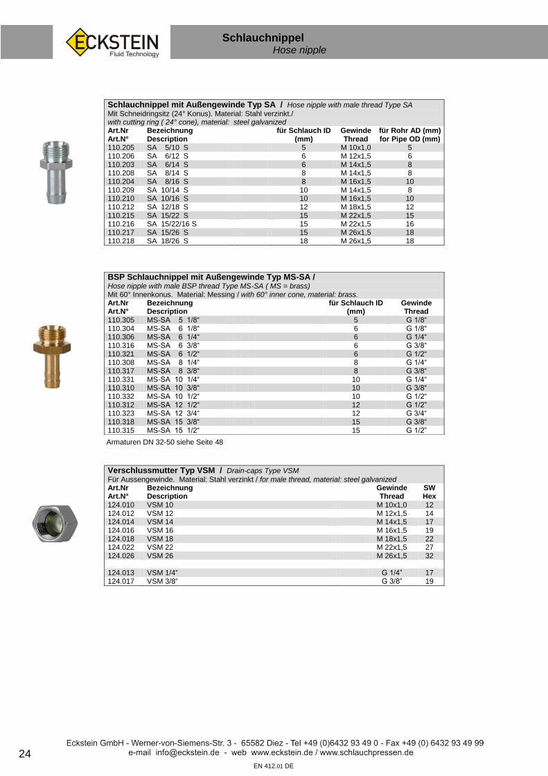
Schlauchnippel mit Außengewinde Typ SA / Hose nipple with male thread Type SA
Mit Schneidringsitz (24° Konus). Material: Stahl verzinkt./ with cutting ring ( 24° cone), material: steel galvanized Art.Nr Art.N°
Bezeichnung Description
für Schlauch ID (mm)
Gewinde Thread
für Rohr AD (mm) for Pipe OD (mm)
110.205 SA 5/10 S 5 M 10x1,0 5 110.206 SA 6/12 S 6 M 12x1,5 6 110.203 SA 6/14 S 6 M 14x1,5 8 110.208 SA 8/14 S 8 M 14x1,5 8 110.204 SA 8/16 S 8 M 16x1,5 10 110.209 SA 10/14 S 10 M 14x1,5 8 110.210 SA 10/16 S 10 M 16x1,5 10 110.212 SA 12/18 S 12 M 18x1,5 12 110.215 SA 15/22 S 15 M 22x1,5 15 110.216 SA 15/22/16 S 15 M 22x1,5 16 110.217 SA 15/26 S 15 M 26x1,5 18 110.218 SA 18/26 S 18 M 26x1,5 18
BSP Schlauchnippel mit Außengewinde Typ MS-SA / Hose nipple with male BSP thread Type MS-SA ( MS = brass) Mit 60° Innenkonus. Material: Messing / with 60° inner cone, material: brass. Art.Nr Art.N°
Bezeichnung Description
für Schlauch ID (mm)
Gewinde Thread
110.305 MS-SA 5 1/8“ 5 G 1/8“ 110.304 MS-SA 6 1/8“ 6 G 1/8“ 110.306 MS-SA 6 1/4“ 6 G 1/4“ 110.316 MS-SA 6 3/8“ 6 G 3/8“ 110.321 MS-SA 6 1/2“ 6 G 1/2“ 110.308 MS-SA 8 1/4“ 8 G 1/4“ 110.317 MS-SA 8 3/8“ 8 G 3/8“ 110.331 MS-SA 10 1/4“ 10 G 1/4“ 110.310 MS-SA 10 3/8“ 10 G 3/8“ 110.332 MS-SA 10 1/2“ 10 G 1/2“ 110.312 MS-SA 12 1/2“ 12 G 1/2” 110.323 MS-SA 12 3/4“ 12 G 3/4“ 110.318 MS-SA 15 3/8“ 15 G 3/8“ 110.315 MS-SA 15 1/2“ 15 G 1/2”
Verschlussmutter Typ VSM / Drain-caps Type VSM
Für Aussengewinde. Material: Stahl verzinkt / for male thread, material: steel galvanized Art.Nr Art.N°
Bezeichnung Description
Gewinde Thread
SW Hex
124.010 VSM 10 M 10x1,0 12 124.012 VSM 12 M 12x1,5 14 124.014 VSM 14 M 14x1,5 17 124.016 VSM 16 M 16x1,5 19 124.018 VSM 18 M 18x1,5 22 124.022 VSM 22 M 22x1,5 27 124.026 VSM 26 M 26x1,5 32 124.013 VSM 1/4“ G 1/4” 17 124.017 VSM 3/8“ G 3/8” 19
Armaturen DN 32-50 siehe Seite 48
25
Rohrstutzen Schlauchnippel Hose nipple
sf
EN 412.01 DE
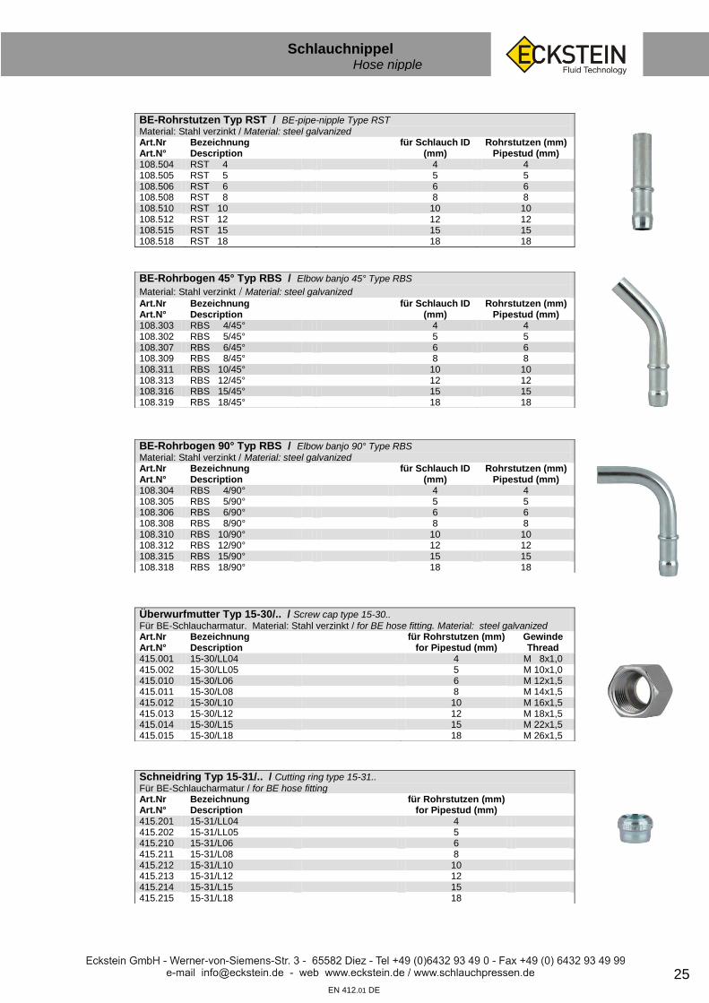
BE-Rohrstutzen Typ RST / BE-pipe-nipple Type RST
Material: Stahl verzinkt / Material: steel galvanized Art.Nr Art.N°
Bezeichnung Description
für Schlauch ID (mm)
Rohrstutzen (mm) Pipestud (mm)
108.504 RST 4 4 4 108.505 RST 5 5 5 108.506 RST 6 6 6 108.508 RST 8 8 8 108.510 RST 10 10 10 108.512 RST 12 12 12 108.515 RST 15 15 15 108.518 RST 18 18 18
BE-Rohrbogen 45° Typ RBS / Elbow banjo 45° Type RBS
Material: Stahl verzinkt / Material: steel galvanized
Art.Nr Art.N°
Bezeichnung Description
für Schlauch ID (mm)
Rohrstutzen (mm) Pipestud (mm)
108.303 RBS 4/45° 4 4 108.302 RBS 5/45° 5 5 108.307 RBS 6/45° 6 6 108.309 RBS 8/45° 8 8 108.311 RBS 10/45° 10 10 108.313 RBS 12/45° 12 12 108.316 RBS 15/45° 15 15 108.319 RBS 18/45° 18 18
BE-Rohrbogen 90° Typ RBS / Elbow banjo 90° Type RBS
Material: Stahl verzinkt / Material: steel galvanized Art.Nr Art.N°
Bezeichnung Description
für Schlauch ID (mm)
Rohrstutzen (mm) Pipestud (mm)
108.304 RBS 4/90° 4 4 108.305 RBS 5/90° 5 5 108.306 RBS 6/90° 6 6 108.308 RBS 8/90° 8 8 108.310 RBS 10/90° 10 10 108.312 RBS 12/90° 12 12 108.315 RBS 15/90° 15 15 108.318 RBS 18/90° 18 18
Überwurfmutter Typ 15-30/.. / Screw cap type 15-30..
Für BE-Schlaucharmatur. Material: Stahl verzinkt / for BE hose fitting. Material: steel galvanized Art.Nr Art.N°
Bezeichnung Description
für Rohrstutzen (mm) for Pipestud (mm)
Gewinde Thread
415.001 15-30/LL04 4 M 8x1,0 415.002 15-30/LL05 5 M 10x1,0 415.010 15-30/L06 6 M 12x1,5 415.011 15-30/L08 8 M 14x1,5 415.012 15-30/L10 10 M 16x1,5 415.013 15-30/L12 12 M 18x1,5 415.014 15-30/L15 15 M 22x1,5 415.015 15-30/L18 18 M 26x1,5
Schneidring Typ 15-31/.. / Cutting ring type 15-31..
Für BE-Schlaucharmatur / for BE hose fitting Art.Nr Art.N°
Bezeichnung Description
für Rohrstutzen (mm) for Pipestud (mm)
415.201 15-31/LL04 4 415.202 15-31/LL05 5 415.210 15-31/L06 6 415.211 15-31/L08 8 415.212 15-31/L10 10 415.213 15-31/L12 12 415.214 15-31/L15 15 415.215 15-31/L18 18

26 EN 412.01 DE
Ringnippel Banjo nipple
sf
Ringschlauchnippel Typ RS / Banjo nipple Type RS
Ähnlich DIN 7642. Material: Stahl verzinkt. / Similar to DIN 7642, material: steel galvanized Art.Nr Art.N°
Bezeichnung Description
für Schlauch ID
(mm) Ring-Ø (mm)
106.006 RS 5/ 6 5 6 106.008 RS 5/ 8 5 8 106.010 RS 6/10 6 10 ~ 1/8“ 106.012 RS 6/12 6 12 106.014 RS 6/14 6 14 ~ 1/4“ 106.110 RS 8/10 8 10 ~ 1/8“ 106.112 RS 8/12 8 12 106.114 RS 8/14 8 14 ~ 1/4“ 106.212 RS 10/12 10 12 106.214 RS 10/14 10 14 ~ 1/4“ 106.216 RS 10/16 10 16 106.218 RS 10/18 10 18 106.314 RS 12/14 12 14 ~ 1/4“ 106.316 RS 12/16 12 16 106.318 RS 12/18 12 18 106.418 RS 15/18 15 18 106.422 RS 15/22 15 22 ~ 1/2“ 106.426 RS 15/26 15 26 106.522 RS 18/22 18 22 ~ 1/2“ 106.526 RS 18/26 18 26 106.015 RS 6 1/4“ 6 1/4“ 106.113 RS 8 1/4“ 8 1/4“ 106.116 RS 8 3/8“ 8 3/8“ 106.217 RS 10 3/8“ 10 3/8“ 106.313 RS 12 3/8“ 12 3/8“
Doppel-Ringschlauchnippel Typ DRS / Twin banjo nipple Type DRS
Material: Stahl verzinkt / material: steel galvanized Art.Nr Art.N°
Bezeichnung Description
für Schlauch ID (mm)
Ring-Ø (mm)
106.808 DRS 5/ 8 5 8 106.810 DRS 6/10 6 10 ~ 1/8“ 106.812 DRS 8/12 8 12 106.814 DRS 10/14 10 14 ~ 1/4“
Rohrbogen 90° mit Ring Typ RBR / Elbow banjo 90° Type RBR
Ring horizontal. Material: Stahl verzinkt. / Bore horizontal. material: steel galvanized Art.Nr Art.N°
Bezeichnung Description
für Schlauch ID
(mm) Ring-Ø (mm)
108.008 RBR 5/ 8/ 90° 5 8 108.010 RBR 6/10/ 90° 6 10 ~ 1/8“ 108.012 RBR 8/12/ 90° 8 12 108.014 RBR 10/14/ 90° 10 14 ~ 1/4“ 108.016 RBR 12/16/ 90° 12 16
Ringgewindestück Typ R-G-L / Ring connection piece Type R-G-L
Mit Schneidringsitz 24°. Material: Stahl verzinkt / with cutting ring 24°. material: steel galvanized Art.Nr Art.N°
Bezeichnung Description
Ring-Ø (mm) Gewinde Thread
für Rohr AD (mm) for Pipe OD (mm)
106.950 R 8 G 10 LL 5 8 M 10x1,0 5 106.952 R 10 G 12 L 6 10 ~ 1/8” M 12x1,5 6 106.954 R 12 G 14 L 8 12 M 14x1,5 8 106.956 R 14 G 14 L 8 14 ~ 1/4“ M 14x1,5 8 106.958 R 14 G 16 L 10 14 ~ 1/4“ M 16x1,5 10 106.959 R 16 G 16 L 10 16 M 16x1,5 10 106.960 R 16 G 18 L 12 16 M 18x1,5 12 106.961 R 18 G 18 L 12 18 M 18x1,5 12 106.962 R 18 G 22 L 15 18 M 22x1,5 15 106.964 R 22 G 22 L 15 22 ~ 1/2” M 22x1,5 15 106.963 R 22 G 26 L 18 26 M 26x1,5 18

27 EN 412.01 DE
Ringnippel Banjo nipple
sf
Ringgewindestück Typ R.. G.. / Mit 60° Innenkonus. Material: Stahl verzinkt. Material: steel galvanized Art.Nr Art.N°
Bezeichnung Description
Ring-Ø (mm) Gewinde Thread
106.908 R 8 G 10 8 M 10x1,0 106.910 R 10 G 12 10 M 12x1,5 106.911 R 12 G 12 12 M 12x1,5 106.912 R 12 G 14 12 M 14x1,5 106.914 R 14 G 14 14 M 14x1,5 106.915 R 14 G 16 14 M 16x1,5 106.917 R 16 G 16 16 M 16x1,5 106.916 R 16 G 18 16 M 18x1,5 106.918 R 18 G 22 18 M 22x1,5 106.913 R 14 G 1/4” 14 G 1/4” 106.919 R 16 G 3/8” 16 G 3/8”
Hohlschraube Typ HS / Hollow screw Type HS
Ähnlich DIN 7643. Material: Stahl verzinkt. / Similar to DIN 7643, material: steel galvanized Art.Nr Art.N°
Bezeichnung Description
Gewinde Thread
Schaftlänge (mm) Shaft-length (mm)
SW hex
107.006 HS 6 M 6x1,0 17 11 107.008 HS 8 M 8x1,0 17 12 107.009 HS 8x1,25 M 8x1,25 17 12 107.010 HS 10 M 10x1,0 19 14 107.011 HS 10x1,5 M 10x1,5 19 14 107.012 HS 12 M 12x1,5 24 17 107.014 HS 14 M 14x1,5 26 19 107.016 HS 16 M 16x1,5 28 22 107.018 HS 18 M 18x1,5 32 24 107.022 HS 22 M 22x1,5 39 27 107.026 HS 26 M 26x1,5 45 32 107.030 HS 30 M 30x1,5 51 36 107.040 HS 1/8“ G 1/8“ 19 14 107.041 HS 1/4“ (Schaft-Ø 14 mm) G 1/4“ 26 19 107.047 HS 1/4” G 1/4” 26 19 107.042 HS 3/8“ G 3/8“ 28 22 107.043 HS 1/2“ (Schaft-Ø 22 mm) G 1/2“ 39 27 107.044 HS 1/2“ G 1/2“ 39 27 107.045 HS 3/4“ G 3/4“ 45 32 107.046 HS 1“ G 1“ 51 41
Doppel-Hohlschraube Typ DHS / Double hollow screw Type DHS
Für 2 Ringstücke. Material: Stahl verzinkt. / For 2 banjos. material: steel galvanized Art.Nr Art.N°
Bezeichnung Description
Gewinde Thread
Schaftlänge (mm) Shaft-length (mm)
SW hex
107.108 DHS 8 M 8x1,0 27 12 107.110 DHS 10 M 10x1,0 30 14 107.112 DHS 12 M 12x1,5 38 17 107.114 DHS 14 M 14x1,5 42 19 107.116 DHS 16 M 16x1,5 46 22 107.118 DHS 18 M 18x1,5 54 24 107.122 DHS 22 M 22x1,5 66 27 107.126 DHS 26 M 26x1,5 77 32 107.130 DHS 1/8“ G 1/8“ 30 14 107.131 DHS 1/4“ G 1/4“ 41 19 107.132 DHS 3/8“ G 3/8“ 46 33 107.133 DHS 1/2“ G 1/2“ 64 27
Hohlschraube Typ HS Form C / Hollow screw Type HS form C
Ähnlich DIN 7643 C. Material: Stahl verzinkt. / Similar to DIN 7643 C. Material: steel galvanized Art.Nr Art.N°
Bezeichnung Description
Gewinde Thread
Schaftlänge (mm) Shaft-length (mm)
SW hex
107.051 HS 10 Form C M 10x1,0 23 14 107.052 HS 12 Form C M 12x1,5 28 17 107.053 HS 14 Form C M 14x1,5 32 19 107.054 HS 16 Form C M 16x1,5 36 22 107.055 HS 18 Form C M 18x1,5 42 24 107.056 HS 22 Form C M 22x1,5 50 27
28
Lötnippel Solding nipple
sf
EN 412.01 DE
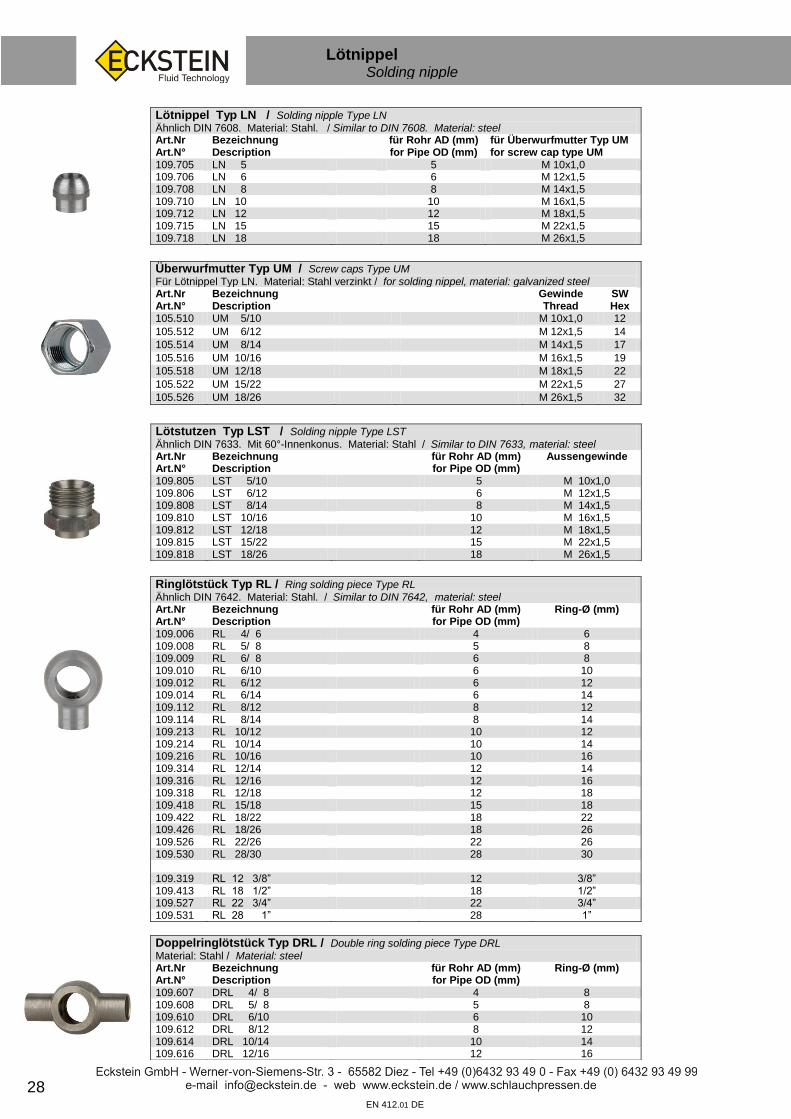
Lötnippel Typ LN / Solding nipple Type LN
Ähnlich DIN 7608. Material: Stahl. / Similar to DIN 7608. Material: steel Art.Nr Art.N°
Bezeichnung Description
für Rohr AD (mm) for Pipe OD (mm)
für Überwurfmutter Typ UM for screw cap type UM
109.705 LN 5 5 M 10x1,0 109.706 LN 6 6 M 12x1,5 109.708 LN 8 8 M 14x1,5 109.710 LN 10 10 M 16x1,5 109.712 LN 12 12 M 18x1,5 109.715 LN 15 15 M 22x1,5 109.718 LN 18 18 M 26x1,5
Überwurfmutter Typ UM / Screw caps Type UM
Für Lötnippel Typ LN. Material: Stahl verzinkt / for solding nippel, material: galvanized steel Art.Nr Art.N°
Bezeichnung Description
Gewinde Thread
SW Hex
105.510 UM 5/10 M 10x1,0 12
105.512 UM 6/12 M 12x1,5 14
105.514 UM 8/14 M 14x1,5 17
105.516 UM 10/16 M 16x1,5 19
105.518 UM 12/18 M 18x1,5 22
105.522 UM 15/22 M 22x1,5 27
105.526 UM 18/26 M 26x1,5 32
Lötstutzen Typ LST / Solding nipple Type LST
Ähnlich DIN 7633. Mit 60°-Innenkonus. Material: Stahl / Similar to DIN 7633, material: steel Art.Nr Art.N°
Bezeichnung Description
für Rohr AD (mm) for Pipe OD (mm)
Aussengewinde
109.805 LST 5/10 5 M 10x1,0 109.806 LST 6/12 6 M 12x1,5 109.808 LST 8/14 8 M 14x1,5 109.810 LST 10/16 10 M 16x1,5 109.812 LST 12/18 12 M 18x1,5 109.815 LST 15/22 15 M 22x1,5 109.818 LST 18/26 18 M 26x1,5
Ringlötstück Typ RL / Ring solding piece Type RL
Ähnlich DIN 7642. Material: Stahl. / Similar to DIN 7642, material: steel Art.Nr Art.N°
Bezeichnung Description
für Rohr AD (mm) for Pipe OD (mm)
Ring-Ø (mm)
109.006 RL 4/ 6 4 6 109.008 RL 5/ 8 5 8 109.009 RL 6/ 8 6 8 109.010 RL 6/10 6 10 109.012 RL 6/12 6 12 109.014 RL 6/14 6 14 109.112 RL 8/12 8 12 109.114 RL 8/14 8 14 109.213 RL 10/12 10 12 109.214 RL 10/14 10 14 109.216 RL 10/16 10 16 109.314 RL 12/14 12 14 109.316 RL 12/16 12 16 109.318 RL 12/18 12 18 109.418 RL 15/18 15 18 109.422 RL 18/22 18 22 109.426 RL 18/26 18 26 109.526 RL 22/26 22 26 109.530 RL 28/30 28 30 109.319 RL 12 3/8” 12 3/8” 109.413 RL 18 1/2” 18 1/2” 109.527 RL 22 3/4” 22 3/4” 109.531 RL 28 1” 28 1”
Doppelringlötstück Typ DRL / Double ring solding piece Type DRL
Material: Stahl / Material: steel Art.Nr Art.N°
Bezeichnung Description
für Rohr AD (mm) for Pipe OD (mm)
Ring-Ø (mm)
109.607 DRL 4/ 8 4 8 109.608 DRL 5/ 8 5 8 109.610 DRL 6/10 6 10 109.612 DRL 8/12 8 12 109.614 DRL 10/14 10 14 109.616 DRL 12/16 12 16

29
Verschlussschrauben Drain plugs
sf
EN 412.01 DE
Verschlussstopfen DIN 910 Typ VSS / Drain-plugs DIN 910 Type VSS
Mit Aussensechskant. Material: Stahl verzinkt / With outside hex. Material: steel galvanized Art.Nr Art.N°
Bezeichnung Description
Gewinde Thread
SW Hex
124.110 VSS 10 M 10x1,0 10 124.112 VSS 12 M 12x1,5 13 124.114 VSS 14 M 14x1,5 13 124.116 VSS 16 M 16x1,5 17 124.118 VSS 18 M 18x1,5 17 124.120 VSS 20 M 20x1,5 19 124.122 VSS 22 M 22x1,5 19 124.124 VSS 24 M 24x1,5 22 124.126 VSS 26 M 26x1,5 24 124.130 VSS 30 M 30x1,5 24 124.209 VSS 1/8“ G 1/8“ 10 124.213 VSS 1/4“ G 1/4“ 13 124.217 VSS 3/8“ G 3/8“ 17 124.221 VSS 1/2“ G 1/2“ 19 124.227 VSS 3/4“ G 3/4” 24 124.233 VSS 1“ G 1“ 27
Verschlussstopfen DIN 908 Typ IVSS / Drain-plugs DIN 908 Type IVSS
Mit Innensechskant. Material: Stahl verzinkt / With inner hex. Material: steel galvanized Art.Nr Art.N°
Bezeichnung Description
Gewinde Thread
Innensechskant (mm) Inside hexagon (mm)
124.310 IVSS 10 M 10x1,0 5 124.312 IVSS 12 M 12x1,5 6 124.314 IVSS 14 M 14x1,5 6 124.316 IVSS 16 M 16x1,5 8 124.318 IVSS 18 M 18x1,5 8 124.320 IVSS 20 M 20x1,5 10 124.322 IVSS 22 M 22x1,5 10 124.324 IVSS 24 M 24x1,5 12 124.326 IVSS 26 M 26x1,5 12 124.327 IVSS 27 M 27x2,0 124.330 IVSS 30 M 30x1,5 17 124.409 IVSS 1/8“ G 1/8” 5 124.413 IVSS 1/4“ G 1/4” 6 124.417 IVSS 3/8“ G 3/8” 8 124.421 IVSS 1/2“ G 1/2” 10 124.423 IVSS 1/2” Magnet G 1/2” 10 124.427 IVSS 3/4“ G 3/4” 12 124.429 IVSS 3/4” Magnet G 3/4” 12 124.433 IVSS 1“ G 1” 17
Verschlussstopfen DIN 906 Typ IVSK / Drain-plugs DIN 908 Type IVSK
Mit Innensechskant und kegligem Zoll-/ metrischen Gewinde. Material: Stahl verzinkt. With inside hex. Inch/metric thread taper. Material: steel galvanized Art.Nr Art.N°
Bezeichnung Description
Gewinde Thread
Innensechskant (mm) Inside hexagon (mm)
124.336 IVSK 6 M 6x1,0 3 124.338 IVSK 8 M 8x1,0 4 124.340 IVSK 10 M 10x1,0 5 124.342 IVSK 12 M 12x1,5 6 124.344 IVSK 14 M 14x1,5 7 124.346 IVSK 16 M 16x1,5 8 124.348 IVSK 18 M 18x1,5 8 124.350 IVSK 20 M 20x1,5 10 124.352 IVSK 22 M 22x1,5 10 124.353 IVSK 24 M 24x1,5 12 124.354 IVSK 26 M 26x1,5 12 124.355 IVSK 30 M 30x1,5 17 124.410 IVSK 1/8“ R 1/8” 5 124.414 IVSK 1/4” R 1/4” 6 124.418 IVSK 3/8“ R 3/8” 8 124.422 IVSK 1/2” R 1/2” 10 124.428 IVSK 3/4” R 3/4” 12 124.434 IVSK 1” R 1” 12

30 EN 412.02 DE
Trink- & Heißwasser Hot- & drinking water
sf
Trink- und Heisswasserschlauch Typ TWS / Schlauchseele aus hochwertigem Butyl-Kautschuk mit einer Umflechtung aus Edelstahldraht. KTW- und DVGW-Zulassung, Betriebstemperatur -30°C bis +100°C (kurzzeitig bis +110°C) High-quality rubber (butyl basis) stainless steel wire braided. Tested according DVGW - KTW. Temperature range: -30°C up to +100°C. Art.Nr Art.N°
Bezeichnung Description
ID (mm)
AD (mm)
Betriebsdruck (bar)
101.638 TWS 6 5,5 10,0 10 101.639 TWS 8 8,0 11,0 10 101.640 TWS 10 9,5 13,0 10 101.641 TWS 12 12,5 17,0 10 101.647 TWS 15 14,5 21,0 10 101.642 TWS 20 19,0 26,0 10 101.643 TWS 25 25,0 33,5 10 101.644 TWS 32 32,0 41,8 10 101.645 TWS 40 40,0 51,0 10 101.646 TWS 50 50,0 63,0 10
Schlauchnippel Typ MV-S.. F / Hose nipples type MV-S.. F
Flachdichtend. Material: Messing, vernickelt / Flat sealing. Material: brass, nickel plated Art.Nr Art.N°
Bezeichnung Description
Passende UM Suitable for screw cap
110.392 MV-S 6 1/4" F 110.417 110.394 MV-S 8 1/4" F 110.417 110.395 MV-S 8 3/8" F 110.419 110.396 MV-S 8 1/2" F 110.431 110.397 MV-S 8 3/4" F 110.424 110.398 MV-S 10 3/8" F 110.419 110.399 MV-S 10 1/2" F 110.431 110.407 MV-S 10 3/4" F 110.424 110.400 MV-S 12 1/2" F 110.421 110.401 MV-S 12 3/4" F 110.424 110.402 MV-S 15 1/2" F 110.421 110.403 MV-S 15 3/4" F 110.425 110.404 MV-S 15 1" F 110.426 110.405 MV-S 20 3/4" F 110.425 110.406 MV-S 20 1" F 110.426 110.408 MV-S 25 1" F 110.426 110.409 MV-S 25 1.1/4” F 110.427 110.412 MV-S 32 1.1/4" F 110.428 110.414 MV-S 40 1.1/2" F 110.429 110.415 MV-S 50 2" F 110.430
Überwurfmutter Typ MV-UM / Screw cap type MV-UM
Material: Messing, vernickelt / Material: brass, nickel plated Art.Nr Art.N°
Bezeichnung Description
Gewinde Thread
Bodenloch (mm)
SW
110.418 MV-UM 1/4" G 1/4“ 9,5 17 110.419 MV-UM 3/8" G 3/8“ 13,0 19 110.431 MV-UM 1/2“ G 1/2“ 14,5 24 110.420 MV-UM 1/2" G 1/2" 16,3 24 110.421 MV-UM 1/2" G 1/2" 16,8 24 110.422 MV-UM 5/8" G 5/8" 14,8 26 110.424 MV-UM 3/4" G 3/4“ 18,5 29 110.425 MV-UM 3/4" G 3/4“ 21,5 30 110.426 MV-UM 1" G 1“ 27,5 37 110.427 MV-UM 1.1/4" G 1.1/4“ 34,2 46 110.428 MV-UM 1.1/4" G 1.1/4“ 35,5 46 110.429 MV-UM 1.1/2" G 1.1/2“ 42,0 51 110.430 MV-UM 2" G 2“ 52,0 66

31 EN 412.02 DE
Trink- & Heißwasser Hot- & drinking water
sf
Rohrbogen mit Überwurfmutter Typ MV-RBU..F/Pipe Elbow with screw cap type MV-RBU..F
Flachdichtend. Material: Messing, vernickelt / Flat sealing. Material: brass, nickel plated Art.Nr Art.N°
Bezeichnung Description
Gewinde Thread
110.436 MV-RBU 8 1/4" F G 1/4“ 110.437 MV-RBU 8 3/8" F G 3/8“ 110.438 MV-RBU 10 3/8" F G 3/8“ 110.439 MV-RBU 10 1/2" F G 1/2" 110.452 MV-RBU 10 3/4" F G 3/4“ 110.440 MV-RBU 12 1/2" F G 1/2" 110.441 MV-RBU 12 3/4" F G 3/4“ 110.442 MV-RBU 15 1/2" F G 1/2" 110.443 MV-RBU 15 3/4" F G 3/4“ 110.445 MV-RBU 20 3/4" F G 3/4“ 110.446 MV-RBU 20 1" F G 1“ 110.449 MV-RBU 25 1" F G 1“ 110.450 MV-RBU 25 1.1/4" F G 1.1/4“ 110.451 VA-RBU 32 1.1/4" F * * Bogen in Edelstahl / stainless steel G 1.1/4“ 110.454 VA-RBU 40 1.1/2" F* * Bogen in Edelstahl / stainless steel G 1.1/2“
Schlauchnippel mit Außengewinde Typ MV-SA..F / Male thread hose nipple type MV-SA..F Flachdichtend. Material: Messing, vernickelt / Flat sealing. Material: brass, nickel plated. Art.Nr Art.N°
Bezeichnung Description
Gewinde Thread
110.640 MV-SA 06 1/8" F G 1/8“ 110.641 MV-SA 06 1/4" F G 1/4“ 110.642 MV-SA 06 3/8" F G 3/8“ 110.645 MV-SA 08 1/4" F G 1/4“ 110.646 MV-SA 08 3/8" F G 3/8“ 110.647 MV-SA 08 1/2" F G 1/2" 110.649 MV-SA 08 3/4" F G 3/4“ 110.650 MV-SA 10 3/8" F G 3/8“ 110.651 MV-SA 10 1/2" F G 1/2" 110.653 MV-SA 10 3/4" F G 3/4“ 110.655 MV-SA 12 3/8" F G 3/8“ 110.460 MV-SA 12 1/2" F G 1/2" 110.658 MV-SA 12 3/4" F G 3/4“ 110.462 MV-SA 15 1/2" F G 1/2" 110.461 MV-SA 15 3/4" F G 3/4“ 110.465 MV-SA 20 3/4" F G 3/4“ 110.466 MV-SA 20 1" F G 1“ 110.469 MV-SA 25 1" F G 1“ 110.470 MV-SA 25 1.1/4" F G 1.1/4“ 110.471 MV-SA 32 1.1/4" F G 1.1/4“ 110.474 MV-SA 40 1.1/2" F G 1.1/2“ 110.476 MV-SA 50 2" F G 2“
Fiberdichtungen Typ FD / Fiber gasket type FD
Art.Nr Art.N°
Bezeichnung Description
110.480 FD 3/8” 110.482 FD 1/2” 110.484 FD 3/4” 110.486 FD 1” 110.488 FD 1.1/4“ 110.489 FD 1.1/2“ 110.487 FD 2“
Doppelstutzen zöllig Typ MV-DST..F / Male thread nipple type MV-DST..F
Material: Messing, vernickelt / Material: brass, nickel plated. Art.Nr Art.N°
Bezeichnung Description
Gewinde Thread
110.490 MV-DST 1/4" F G 1/4“ 110.491 MV-DST 3/8" F G 3/8“ 110.492 MV-DST 1/2" F G 1/2" 110.494 MV-DST 3/4" F G 3/4“ 110.496 MV-DST 1" F G 1“ 110.497 MV-DST 1.1/4" F G 1.1/4“ 110.498 MV-DST 1.1/2“ F G 1.1/2“

32
PA-Rohr + Armaturen Polyamide pipe + fittings
sf
EN 412.01 DE
Polyamid-Rohr PA 11/12 DIN 74324 Typ PAR / Polyamide pipe PA 11/12 Type PAR
Temperaturbereich -60°C bis +100°C, Farbe: Schwarz. Weitere Farben auf Anfrage. Angegebener Betriebsdruck bei 20°C Temperature range: -60°C up to +100°C, color: black. Other colors on request. Art.Nr Art.N°
Bezeichnung Description
AD (mm)
ID (mm)
Betriebsdruck (bar) Working pressure (bar)
120.001 PAR 4/1,0 4 2 45 120.005 PAR 5/1,0 5 3 34 120.010 PAR 6/1,0 6 4 27 120.015 PAR 8/1,0 8 6 19 120.017 PAR 8/1,5 8 5 31 120.020 PAR 9/1,5 9 6 27 120.025 PAR 10/1,0 10 8 15 120.027 PAR 10/1,25 10 7,5 19 120.069 PAR 10/1,5 10 7 30 120.028 PAR 10/2,0 10 6 34 120.030 PAR 11/1,5 11 8 21 120.035 PAR 12/1,5 12 9 19 120.040 PAR 12/2,0 12 8 27 120.045 PAR 14/2,0 14 10 22 120.050 PAR 15/1,5 15 12 15 120.056 PAR 16/2,0 16 12 19 120.060 PAR 18/2,0 18 14 16 120.065 PAR 22/2,0 22 18 13
Verstärkungshülse für PA-Rohr Typ VHP / Sleeves for PA-tube Type VHP
Material: Messing / Material: brass Art.Nr Art.N°
Bezeichnung Description
für Rohr ID (mm)
PE
120.200 VHP 4/1,0 2 100 120.205 VHP 5/1,0 3 100 120.210 VHP 6/1,0 4 100 120.215 VHP 8/1,0 6 100 120.217 VHP 8/1,5 5 100 120.215 VHP 9/1,5 6 100 120.225 VHP 10/1,0 8 100 120.227 VHP 10/1,25 7,5 100 120.228 VHP 10/1,5 7 100 120.215 VHP 10/2,0 6 100 120.225 VHP 11/1,5 8 100 120.235 VHP 12/1,5 9 100 120.225 VHP 12/2,0 8 100 120.245 VHP 14/2,0 10 50 120.250 VHP 15/1,5 12 50 120.250 VHP 16/2,0 12 50 120.260 VHP 18/2,0 14 50 120.265 VHP 22/2,0 18 50
Schlauchnippel für PA-Rohr Typ SP / Hose nipple for PA-tube Type SP
Material: Stahl verzinkt / Material: galvanized steel Art.Nr Art.N°
Bezeichnung Description
für Rohr ID (mm) for Pipe ID (mm)
für Überwurfmutter Typ UM fits with screw cap type UM
120.600 SP 4/10 4 M 10x1,0 + G 1/8“ 120.601 SP 4/12 4 M 12x1,5 120.605 SP 5/12 5 M 12x1,5 120.606 SP 5/14 5 M 14x1,5 + G 1/4“ 120.610 SP 6/14 6 M 14x1,5 + G 1/4“ 120.611 SP 6/16 6 M 16x1,5 + G 3/8“ 120.615 SP 8/14 8 M 14x1,5 + G 1/4“ 120.616 SP 8/16 8 M 16x1,5 + G 3/8“ 120.620 SP 10/16 9 / 10 M 16x1,5 + G 3/8“
Überwurfmutter Typ UM / Screw caps Type UM
Für Schlauchnippel Typ SP. Material: Stahl verzinkt for hose nipple type SP, material: steel galvanized Art.Nr Art.N°
Bezeichnung Description
Gewinde Thread
SW Hex
105.510 UM 5/10 M 10x1,0 12
105.512 UM 6/12 M 12x1,5 14
105.514 UM 8/14 M 14x1,5 17
105.516 UM 10/16 M 16x1,5 19
105.605 UM 1/8“ G 1/8“ 14
105.608 UM 1/4“ G 1/4“ 17
105.610 UM 3/8“ G 3/8“ 19

33
PA-Rohr + Armaturen Polyamide pipe + fittings
sf
EN 412.01 DE
Außengewindearmatur für PA-Rohr Typ SAP / Outside thread fittings for PA pipe type SAP
Aussengewinde mit Schneidringsitz (24° Innenkonus). Material: Stahl verzinkt Outside thread with cutting ring (24° inside cone), material: galvanized steel Art.Nr Art.N°
Bezeichnung Description
für PA-Rohr ID (mm) for PA-Pipe ID (mm)
Aussengewinde für Rohr AD (mm) for Pipe OD (mm)
120.701 SAP 4/6 4 M 12x1,5 6 120.705 SAP 5/6 5 M 12x1,5 6 120.706 SAP 5/8 5 M 14x1,5 8 120.710 SAP 6/8 6 M 14x1,5 8 120.715 SAP 8/8 8 M 14x1,5 8 120.716 SAP 8/10 8 M 16x1,5 10 120.720 SAP 10/10 10 M 16x1,5 10 120.722 SAP 10/12 10 M 16x1,5 12
Rohrstutzen für PA-Rohr Typ RSTP / BE-pipe-nipple for PA-tube Type RSTP
Material: Stahl verzinkt / Material: steel galvanized Art.Nr Art.N°
Bezeichnung Description
für PA-Rohr ID (mm) for PA-Pipe ID (mm)
Rohrstutzen (mm) Pipe stud (mm)
120.399 RSTP 3/ 6 3 6 120.400 RSTP 4/ 6 4 6 120.405 RSTP 5/ 6 5 6 120.410 RSTP 6/ 8 6 8 120.415 RSTP 8/10 8 10 120.420 RSTP 10/10 9 / 10 10 120.425 RSTP 10/12 9 / 10 12
Überwurfmutter Typ 15-30/.. / Screw cap type 15-30/..
Für Rohrstutzen Typ RSTP. Material: Stahl verzinkt. For pipe connector type RSTP, material: steel galvanized Art.Nr Art.N°
Bezeichnung Description
für Rohrstutzen (mm) for Pipestud (mm)
Gewinde Thread
415.010 15-30/L06 6 M 12x1,5 415.011 15-30/L08 8 M 14x1,5 415.012 15-30/L10 10 M 16x1,5 415.013 15-30/L12 12 M 18x1,5
Schneidring Typ 15-31/.. / Cutting ring Type 15-31/..
Für Rohrstutzen Typ RSTP/ For pipe connector type RSTP Art.Nr Art.N°
Bezeichnung Description
für Rohrstutzen (mm) for Pipestud (mm)
415.210 15-31/L06 6 415.211 15-31/L08 8 415.212 15-31/L10 10 415.213 15-31/L12 12
Doppelkonen Typ DKN / Stuffing cones Type DKN
Messing / Brass Art.Nr Art.N°
Bezeichnung Description
für PA-Rohr AD (mm) for PA-Pipe OD (mm)
PE
128.000 DKN 4 4 100 128.001 DKN 5 5 100 128.002 DKN 6 6 100 128.003 DKN 8 8 100 128.004 DKN 10 10 100 128.005 DKN 12 12 100
Ringschlauchnippel für PA-Rohr Typ RSP / Banjo for PA-tube Type RSP
Material: Stahl verzinkt / Material: steel galvanized Art.Nr Art.N°
Bezeichnung Description
für PA-Rohr ID (mm) for PA-Pipe ID (mm)
Ring (mm)
Bore (mm) 120.500 RSP 3/ 8 3 8 120.505 RSP 4/ 8 4 8 120.506 RSP 4/10 4 10 120.507 RSP 4/12 4 12 120.508 RSP 4/14 4 14 120.509 RSP 4/16 4 16 120.515 RSP 5/10 5 10 120.516 RSP 5/12 5 12 120.520 RSP 6/10 6 10 120.521 RSP 6/12 6 12 120.522 RSP 6/14 6 14 120.523 RSP 6/16 6 16 120.530 RSP 8/12 8 12 120.531 RSP 8/14 8 14 120.532 RSP 8/16 8 16 120.540 RSP 10/14 9 / 10 14 120.541 RSP 10/16 9 / 10 16
34 EN 412.01 DE
Einschraub-Steckverbinder Plug connector
sf
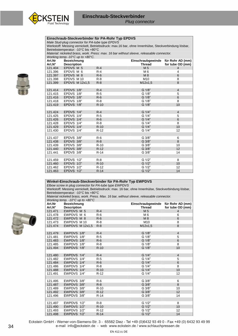
Winkel-Einschraub-Steckverbinder für PA-Rohr Typ EWPDVS Elbow screw in plug connector for PA-tube type EWPDVS Werkstoff: Messing vernickelt, Betriebsdruck: max. 16 bar, ohne Innenhülse, Steckverbindung lösbar, Betriebstemperatur: -10°C bis +80°C Material nickeled brass, work. Press. Max. 16 bar, without sleeve, releasable connector. Working temp. -10°C up to +80°C Art.Nr Art.N°
Bezeichnung Description
Einschraubgewinde Thread
für Rohr AD (mm) for tube OD (mm)
121.471 EWPDVS M 5 R-4 M 5 4 121.478 EWPDVS M 6 R-6 M 6 6 121.472 EWPDVS M 8 R-6 M 8 6 121.473 EWPDVS M 10 R-8 M10 8 121.474 EWPDVS M 12x1,5 R-8 M12x1,5 8 121.479 EWPDVS 1/8“ R-4 G 1/8” 4 121.481 EWPDVS 1/8“ R-5 G 1/8” 5 121.483 EWPDVS 1/8“ R-6 G 1/8” 6 121.485 EWPDVS 1/8“ R-8 G 1/8” 8 121.494 EWPDVS 1/8” R-10 G 1/8” 10 121.480 EWPDVS 1/4” R-4 G 1/4” 4 121.482 EWPDVS 1/4“ R-5 G 1/4” 5 121.484 EWPDVS 1/4“ R-6 G 1/4” 6 121.486 EWPDVS 1/4“ R-8 G 1/4” 8 121.488 EWPDVS 1/4“ R-10 G 1/4” 10 121.491 EWPDVS 1/4“ R-12 G 1/4” 12 121.495 EWPDVS 3/8” R-6 G 3/8” 6 121.487 EWPDVS 3/8“ R-8 G 3/8” 8 121.489 EWPDVS 3/8“ R-10 G 3/8” 10 121.492 EWPDVS 3/8“ R-12 G 3/8” 12 121.496 EWPDVS 3/8” R-14 G 3/8” 14 121.497 EWPDVS 1/2” R-8 G 1/2” 8 121.490 EWPDVS 1/2“ R-10 G 1/2” 10 121.493 EWPDVS 1/2“ R-12 G 1/2” 12 121.498 EWPDVS 1/2” R-14 G 1/2” 14
Einschraub-Steckverbinder für PA-Rohr Typ EPDVS Male Stud-plug connector for PA-tube type EPDVS Werkstoff: Messing vernickelt, Betriebsdruck: max.16 bar, ohne Innenhülse, Steckverbindung lösbar, Betriebstemperatur: -10°C bis +80°C Material: nickeled brass, work. Press: max. 16 bar without sleeve, releasable connector. Working temp.-10°C up to +80°C. Art.Nr Art.N°
Bezeichnung Description
Einschraubgewinde Thread
für Rohr AD (mm) for tube OD (mm)
121.404 EPDVS M 5 R-4 M 5 4 121.396 EPDVS M 6 R-4 M 6 4 121.397 EPDVS M 8 R-6 M 8 6 121.398 EPDVS M 10 R-8 M10 8 121.399 EPDVS M 12x1,5 R-8 M12x1,5 8 121.414 EPDVS 1/8“ R-4 G 1/8” 4 121.415 EPDVS 1/8“ R-5 G 1/8” 5 121.416 EPDVS 1/8“ R-6 G 1/8” 6 121.418 EPDVS 1/8“ R-8 G 1/8” 8 121.419 EPDVS 1/8” R-10 G 1/8” 10 121.424 EPDVS 1/4” R-4 G 1/4” 4 121.425 EPDVS 1/4“ R-5 G 1/4” 5 121.426 EPDVS 1/4“ R-6 G 1/4” 6 121.428 EPDVS 1/4“ R-8 G 1/4” 8 121.429 EPDVS 1/4“ R-10 G 1/4” 10 121.430 EPDVS 1/4“ R-12 G 1/4” 12 121.437 EPDVS 3/8” R-6 G 3/8” 6 121.438 EPDVS 3/8“ R-8 G 3/8” 8 121.439 EPDVS 3/8“ R-10 G 3/8” 10 121.440 EPDVS 3/8“ R-12 G 3/8” 12 121.441 EPDVS 3/8” R-14 G 3/8” 14 121.459 EPDVS 1/2” R-8 G 1/2” 8 121.460 EPDVS 1/2“ R-10 G 1/2” 10 121.462 EPDVS 1/2“ R-12 G 1/2” 12 121.463 EPDVS 1/2” R-14 G 1/2” 14

35 EN 412.01 DE
Steckverbinder Plug connector
sf
Steckverbinder ohne Innenhülse für PA-Rohr Typ PDVSO Push in tube fittings without sleeve for PA-tube Type PDVSO Werkstoff: Messing vernickelt / Material: nickeled brass Art.Nr Art.N°
Bezeichnung Description
für Rohr AD (mm) for Tube OD (mm)
121.104 PDVSO 4 4 121.105 PDVSO 5 5 121.106 PDVSO 6 6 121.108 PDVSO 8 8 121.110 PDVSO 10 10 121.112 PDVSO 12 12 121.114 PDVSO 14 14
Winkel-Steckverbinder ohne Innenhülse für PA-Rohr Typ PWVSO Elbow push in tube fittings without sleeve for PA-tube Type PWVSO Werkstoff: Messing vernickelt / Material: nickeled brass Art.Nr Art.N°
Bezeichnung Description
für Rohr AD (mm) for Tube OD (mm)
121.204 PWVSO 4 4 121.205 PWVSO 5 5 121.206 PWVSO 6 6 121.208 PWVSO 8 8 121.210 PWVSO 10 10 121.212 PWVSO 12 12 121.214 PWVSO 14 14
T-Steckverbinder ohne Innenhülse für PA-Rohr Typ PTVSO Werkstoff: Messing vernickelt Art.Nr Art.N°
Bezeichnung Description
für Rohr AD (mm) for Tube OD (mm)
121.304 PTVSO 4 4 121.305 PTVSO 5 5 121.306 PTVSO 6 6 121.308 PTVSO 8 8 121.310 PTVSO 10 10 121.312 PTVSO 12 12 121.314 PTVSO 14 14
Steckverbinder f. PA-Rohr (Druckluftbremse)Typ PDVS Push in connector f. PA-tube (Airbrake) type PDVS Messing mit Innenhülse. TÜV-geprüft. / Brass with inside sleeve. TÜV tested Art.Nr Art.N°
Bezeichnung Description
für Rohr for Pipe
121.006 PDVS 6 6x1,0 121.008 PDVS 8 8x1,0 121.009 PDVS 9 9x1,5 121.010 PDVS 10 10x1,0 121.011 PDVS 11 11x1,5 121.012 PDVS 12 12x1,5 121.014 PDVS 14 14x2,0 121.015 PDVS 15 15x1,5 121.016 PDVS 16 16x2,0
Winkel-Steckverbinder f. PA-Rohr (Druckluftbremse) Typ PWVS
Push in connector f. PA-tube (Airbrake) type PWVS. Messing mit Innenhülse. TÜV-geprüft. Brass with inside sleeve. TÜV tested
Art.Nr Art.N°
Bezeichnung Description
für Rohr for Tube
121.194 PWVS 6 6x1,0 121.195 PWVS 8 8x1,0 121.196 PWVS 10 10x1,0 121.197 PWVS 12 12x1,5 121.198 PWVS 15 15x1,5 121.199 PWVS 16 16x2,0
T-Steckverbinder für PA-Rohr (Druckluftbremse) Typ PTVS
T-push in connector for PA-tube (Airbrake) type PTVS. Messing mit Innenhülse. TÜV-geprüft. / Brass with inside sleeve. TÜV tested. Art.Nr Art.N°
Bezeichnung Description
für Rohr for Tube
121.295 PTVS 6 6x1,0 121.296 PTVS 8 8x1,0 121.297 PTVS 10 10x1,0 121.298 PTVS 12 12x1,5 121.299 PTVS 15 15x1,5

36 EN 412.01 DE
Steckverbinder Plug connector
sf
Kunststoff Steckverbinder für PA-Rohr Typ GST Plastic plug connector for PA tube type GST Art.Nr Art.N°
Bezeichnung Description
für Rohr AD (mm) for Tube OD (mm)
130.947 GST 4 4 130.948 GST 6 6 130.949 GST 8 8 130.950 GST 10 10 130.951 GST 12 12 130.952 GST 15 15 130.970 GST 22 22 130.991 GST 28 28
Kunststoff Steckverbinder für PA-Rohr Typ WST Plastic plug connector for PA tube type WST Art.Nr Art.N°
Bezeichnung Description
für Rohr AD (mm) for Tube OD (mm)
130.944 WST 4 4 130.945 WST 6 6 130.953 WST 8 8 130.954 WST 10 10 130.955 WST 12 12 130.956 WST 15 15 130.971 WST 22 22 130.992 WST 28 28
Kunststoff Steckverbinder für PA-Rohr Typ TST Plastic plug connector for PA tube type TST Art.Nr Art.N°
Bezeichnung Description
für Rohr AD (mm) for Tube OD (mm)
130.946 TST 4 4 130.957 TST 6 6 130.958 TST 8 8 130.959 TST 10 10 130.960 TST 12 12 130.961 TST 15 15 130.972 TST 22 22 130.993 TST 28 28
Reduzier-Kunststoff Steckverbinder für PA-Rohr Typ RED-GST / Reduction Plastic plug connector for PA tube type RED-GST Art.Nr Art.N°
Bezeichnung Description
für Rohr AD A (mm) for Tube OD A (mm)
für Rohr AD B (mm) for Tube OD B (mm)
130.980 RED-GST 4- 6 4 6 130.985 RED-GST 6- 8 6 8 130.988 RED-GST 8-10 8 10 130.989 RED-GST 10-12 10 12 130.990 RED-GST 12-16 12 16
37 EN 412.01 DE
Muffen Sockets
sf
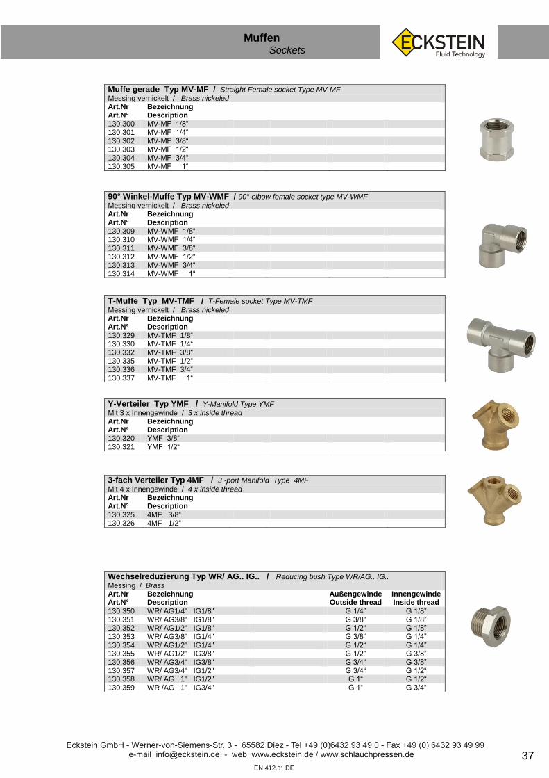
Muffe gerade Typ MV-MF / Straight Female socket Type MV-MF
Messing vernickelt / Brass nickeled Art.Nr Art.N°
Bezeichnung Description
130.300 MV-MF 1/8“ 130.301 MV-MF 1/4“ 130.302 MV-MF 3/8“ 130.303 MV-MF 1/2“ 130.304 MV-MF 3/4“ 130.305 MV-MF 1“
90° Winkel-Muffe Typ MV-WMF / 90° elbow female socket type MV-WMF Messing vernickelt / Brass nickeled Art.Nr Art.N°
Bezeichnung Description
130.309 MV-WMF 1/8“ 130.310 MV-WMF 1/4“ 130.311 MV-WMF 3/8“ 130.312 MV-WMF 1/2“ 130.313 MV-WMF 3/4“ 130.314 MV-WMF 1“
T-Muffe Typ MV-TMF / T-Female socket Type MV-TMF
Messing vernickelt / Brass nickeled Art.Nr Art.N°
Bezeichnung Description
130.329 MV-TMF 1/8“ 130.330 MV-TMF 1/4“ 130.332 MV-TMF 3/8“ 130.335 MV-TMF 1/2“ 130.336 MV-TMF 3/4“ 130.337 MV-TMF 1“
Y-Verteiler Typ YMF / Y-Manifold Type YMF
Mit 3 x Innengewinde / 3 x inside thread Art.Nr Art.N°
Bezeichnung Description
130.320 YMF 3/8“ 130.321 YMF 1/2“
3-fach Verteiler Typ 4MF / 3 -port Manifold Type 4MF
Mit 4 x Innengewinde / 4 x inside thread Art.Nr Art.N°
Bezeichnung Description
130.325 4MF 3/8“ 130.326 4MF 1/2“
Wechselreduzierung Typ WR/ AG.. IG.. / Reducing bush Type WR/AG.. IG..
Messing / Brass Art.Nr Art.N°
Bezeichnung Description
Außengewinde Outside thread
Innengewinde Inside thread
130.350 WR/ AG1/4" IG1/8" G 1/4” G 1/8” 130.351 WR/ AG3/8" IG1/8" G 3/8“ G 1/8” 130.352 WR/ AG1/2" IG1/8" G 1/2“ G 1/8” 130.353 WR/ AG3/8" IG1/4" G 3/8“ G 1/4” 130.354 WR/ AG1/2" IG1/4" G 1/2“ G 1/4” 130.355 WR/ AG1/2" IG3/8" G 1/2“ G 3/8” 130.356 WR/ AG3/4" IG3/8" G 3/4“ G 3/8” 130.357 WR/ AG3/4" IG1/2" G 3/4“ G 1/2“ 130.358 WR/ AG 1" IG1/2" G 1“ G 1/2“ 130.359 WR /AG 1" IG3/4" G 1“ G 3/4“

38 EN 412.01 DE
Absperrventile / Doppelstutzen Valves / straight studs
sf
Kugelhahn Messing Typ MS-BK / Brass ball valve type MS-BK
Messing vernickelt, Temperaturbereich: -15° C bis +150° C, beidseitig zölliges Innengewinde. Kugeldichtung: PTFE Brass nickeled, temperature range: -15°C up to +150°C, both sides inside thread inch Art.Nr Art.N°
Bezeichnung Description
Einbaulänge (mm) Betriebsdruck (bar)
131.001 MS-BK G 1/4” 44 25 131.002 MS-BK G 3/8” 44 25 131.003 MS-BK G 1/2” 50 25 131.004 MS-BK G 3/4” 57 25 131.005 MS-BK G 1” 70 25 131.006 MS-BK G 1 1/4” 80 25 131.007 MS-BK G 1 1/2” 94 25 131.008 MS-BK G 2” 112 25 131.009 MS-BK G 3” 157 16
Mini-Kugelhahn Messing Typ BKM / Mini brass ball valve
Messing verchromt, Temperaturbereich: -30° C bis +90°C, Beidseitig zölliges Innengewinde. Kugeldichtung: PTFE Brass chrome plated. Temperature range: -30°C up to +90°C, both sides inside thread inch Art.Nr Art.N°
Bezeichnung Description
Einbaulänge (mm) Betriebsdruck (bar)
290.054 BKM G 1/8” 40 15 290.055 BKM G 1/4” 40 15 290.056 BKM G 3/8” 40 15 290.057 BKM G 1/2” 46 15
Rückschlagventil Typ RV / Check valve type RV Material: Messing, Dichtung: FKM. Beidseitig zölliges Innengewinde. Betriebsdruck: max.16 bar, Öffnungsdruck: 0,1 bar (G1“) bis 0,5 bar (G1/4“), Betriebstemperatur: max. 180° C Material: Brass, Seal: FKM, both sides inner thread inch, working pres.: max 16 bar, Opening press.: 0,1 bar (G1”) bis 0,5 bar (G1/4”), Work. T°: max 180°C Art.Nr Art.N°
Bezeichnung Description
Länge (mm) SW Hex
130.242 RV G1/4” 53 19 130.243 RV G3/8” 53 19 130.244 RV G1/2” 64 24 130.245 RV G3/4” 58 36 130.246 RV G1” 68 46
Doppelstutzen Typ MS-DST / Straight stud Type DST…MS
Messing / Brass Art.Nr Art.N°
Bezeichnung Description
Länge (mm) SW Hex
122.090 MS-DST 1/8” 21 14 122.091 MS-DST 1/4” 23 17 122.092 MS-DST 3/8” 25 19 122.093 MS-DST 1/2” 29 24 122.094 MS-DST 3/4” 33 32 122.095 MS-DST 1” 42 36 122.096 MS-DST 1 1/4” 39 42 122.097 MS-DST 1 1/2” 50 50 122.098 MS-DST 2” 54 62
Reduzierte Doppelstutzen Typ MS-RDST / Reducing connector type MS-RDST Art.Nr Art.N°
Bezeichnung Description
Länge (mm) SW Hex
122.075 MS-RDST 1/8“ x 1/4“ 22 17 122.076 MS-RDST 1/8“ x 3/8“ 25 19 122.077 MS-RDST 1/4“ x 3/8“ 24 19 122.078 MS-RDST 1/4“ x 1/2“ 29 24 122.079 MS-RDST 3/8“ x 1/2“ 27 24 122.080 MS-RDST 3/8“ x 3/4“ 36 32 122.081 MS-RDST 1/2“ x 3/4“ 33 32 122.082 MS-RDST 1/2“ x1“ 40 36 122.083 MS-RDST 3/4“ x1“ 40 36 122.084 MS-RDST 1“ x1 1/4“ 32 42 122.085 MS-RDST 1“ x1 1/2“ 39 50 122.086 MS-RDST 1 1/4“x1 1/2“ 37 50 122.087 MS-RDST 1 1/2“x2“ 44 62

39 EN 412.01 DE
Manometer / Luftpistolen / Ventilstecker Gauges / blow guns / air chucks
sf
Druckluft-Manometer Typ DM / Air pressure manometer type DM Kunststoffgehäuse, Ø 63 mm, Anschluss G1/4” unten, stehende Ausführung, Skala: bar/psi Plastic body, Ø 63 mm, connection G1/4“ in the bottom, vertical design, scale: bar/psi Art.Nr Art.N°
Bezeichnung Description
Messbereich (bar) Messbereich (psi)
130.225 DM 0-2,5 0 - 2,5 0 - 36 130.226 DM 0-4 0 - 4 0 - 60 130.227 DM 0-6 0 - 6 0 - 90 130.228 DM 0-10 0 - 10 0 - 145 130.229 DM 0-16 0 - 16 0 - 235 130.230 DM 0-25 0 - 25 0 - 360
Druckluft-Manometer Typ DM / Air pressure manometer type DM
Kunststoffgehäuse, Ø 63 mm, Anschluss G1/4” hinten, liegende Ausführung, Skala: bar/psi Plastic body, Ø 63 mm, connection G1/4“ at the back, horizontal design, Scale: bar/psi Art.Nr Art.N°
Bezeichnung Description
Messbereich (bar) Messbereich (psi)
130.235 DM 0-2,5 0 - 2,5 0 - 36 130.236 DM 0-4 0 - 4 0 - 60 130.237 DM 0-6 0 - 6 0 - 90 130.238 DM 0-10 0 - 10 0 - 145 130.239 DM 0-16 0 - 16 0 - 235 130.240 DM 0-25 0 - 25 0 - 360
Ausblasepistole Typ AA 26 SF / Blow gun type AA 26 SF
Material: Alu Art.Nr Art.N°
Bezeichnung Description
130.400 AA 26 SF Aluminium 130.410 VR 12 Verlängerungsrohr für AA 26 SF, Länge 150 mm
Extension tube for AA 26 SF, Length 150 mm
Ausblasepistole Typ AK 13 S-05 / Blow gun Type AK 13 S-25
Material: PVC. Mit Verlängerungsrohr. Innengewinde G 1/4” Material: PVC. With extension tube, inside thread Art.Nr Art.N°
Bezeichnung Description
130.401 AK 13S-05
Spiralschlauch Typ LK / Spiral hose Type LK
Beidseitig mit drehbarer Verschraubung AG 1/4“ und Knickschutzfeder Both side with rotating connection Art.Nr Art.N°
Bezeichnung Description
Anschlüsse Connectors
Max Arbeitslänge Max. working range
130.420 LK 730 G 1/4“ 5 m 130.421 LK 731 G 1/4“ 7 m
Ventilhebelstecker Typ LK / Air chuck Type LK
Messing vernickelt / Brass nickeled Art.Nr Art.N°
Bezeichnung Description
für Schlauch ID (mm)
130.800 LK 800 6 130.801 LK 801 Gummidichtung für Ventilhebelstecker LK 800 /
Rubber gasket for air chuck LK 800
Flügelmutter Typ LK / Wing nut coupling Type LK
Art.Nr Art.N°
Bezeichnung Description
für Schlauch ID (mm)
Gewinde
130.810 LK 810 5 M 16x1,5 130.813 LK 810- 6 6 M 16x1,5 130.814 LK 810- 8 8 M 16x1,5 130.815 LK 810-10 10 M 16x1,5 130.811 LK 811 Ersatzdichtung für LK 810 / Rubber gasket for LK 810
Ventilhebelstecker Typ LK / Air chuck Type LK
Gerade, französische Form / French type Art.Nr Art.N°
Bezeichnung Description
für Schlauch ID (mm)
130.806 LK 806 6 130.807 LK 807 8

40
Wartungseinheit Maintenance unit
sf
EN 412.01 DE
Wartungseinheit Typ WEH / Maintenance unit type WEH
Art.Nr Art.N°
Bezeichnung Description
Innengewinde
130.250 WEH 1/4” G 1/4” 130.255 WEH 3/8” G 3/8” 130.260 WEH 1/2“ G 1/2“
Wasserabscheider Typ WAS / Water separator
Art.Nr Art.N°
Bezeichnung Description
Innengewinde
130.273 WAS 1/4“ G 1/4” 130.279 WAS 3/8“ G 3/8” 130.286 WAS 1/2“ G 1/2“
Öler Typ ÖLR / Oiler ÖLR
Art.Nr Art.N°
Bezeichnung Description
Innengewinde
130.274 ÖLR 1/4“ G 1/4” 130.280 ÖLR 3/8“ G 3/8” 130.287 ÖLR 1/2“ G 1/2“
Druckregler Typ DRE / Pressure control
Art.Nr Art.N°
Bezeichnung Description
Innengewinde
130.275 DRE 1/4” G 1/4” 130.281 DRE 3/8” G 3/8” 130.288 DRE 1/2” G 1/2“
Druckregler mit Wasserabscheider Typ DRW / Pressure control + water separator Art.Nr Art.N°
Bezeichnung Description
Innengewinde
130.278 DRW 1/4” G 1/4” 130.282 DRW 3/8” G 3/8” 130.289 DRW 1/2” G 1/2“
Sinterbronce-Schalldämpfer / Sinter bronze silencer Zur Reduzierung von Abluftgeräuschen an pneumatischen Anlagen. Betriebsdruck max. 10 bar. To reduce the exhaust noise of pneumatic systems. Work. Press. max. 10 bar Art.Nr Art.N°
Bezeichnung Description
000.458 MS-SDS 1/8“ 000.459 MS-SDS 1/4“ 000.460 MS-SDS 3/8“ 000.461 MS-SDS 1/2“
Weitere Typen auf Anfrage lieferbar. Other types on request

41
Pneumatik Steckkupplungen NW5 / NW7,2 Quick connect couplings
EN 412.01 DE
NW 5 Luftkupplungen Typ LK 21 / Quick connect coupling Type LK 21
Messing, Betriebsdruck: max. 35 bar / Brass, working pressure: max. 35 bar Art.Nr Art.N°
Bezeichnung Description
Außengewinde Outside thread
Innengewinde Inside thread
Schlauchtülle (mm)
130.070 21 KAAW 10 G 1/8” 130.071 21 KAAW 13 G 1/4“ 130.072 21 KAIW 10 G 1/8” 130.073 21 KAIW 13 G 1/4“ 130.074 21 KATF 04 4 130.075 21 KATF 06 6 130.085 21 KATF 08 8 130.089 21 KATF 09 9 130.090 21 KATF 10 10
Kupplungsstecker Typ LK 21 / Plug Type LK 21
Messing / Brass 130.078 21 SFAW 10 G 1/8” 130.079 21 SFAW 13 G 1/4“ 130.080 21 SFIW 10 G 1/8” 130.081 21 SFIW 13 G 1/4“ 130.076 21 SFTF 04 4
130.077 21 SFTF 06 6
130.095 21 SFTF 08 8
130.088 21 SFTF 09 9
130.096 21 SFTF 10 10
NW 7,2 Standard Luftkupplungen Typ LK26 / Standard quick connect coupling Type LK 26
Messing, Betriebsdruck: max. 35 bar / Brass, Size 7,2 mm, working pressure 0-35 bar Art.Nr Art.N°
Bezeichnung Description
Außengewinde Outside thread
Innengewinde Inside thread
Schlauchtülle (mm)
130.000 26 KAAW 10 G1/8“ 130.001 26 KAAW 13 G1/4“ 130.002 26 KAAW 17 G3/8“ 130.005 26 KAAW 21 G1/2“ 130.011 26 KAIW 13 G1/4“ 130.012 26 KAIW 17 G3/8“ 130.015 26 KAIW 21 G1/2“ 130.021 26 KATF 06 6 130.360 26 KATF 08 8 130.022 26 KATF 09 9 130.361 26 KATF 10 10 130.025 26 KATF 13 13
Kupplungsstecker Typ LK 26 / Plug Type LK 26
Messing / Brass 130.059 26 SFAW 10 G 1/8”
130.050 26 SFAW 13 G 1/4”
130.051 26 SFAW 17 G 3/8”
130.055 26 SFAW 21 G 1/2”
130.064 26 SFIW 10 G 1/8”
130.060 26 SFIW 13 G 1/4”
130.061 26 SFIW 17 G 3/8”
130.065 26 SFIW 21 G 1/2”
130.030 26 SFTF 06 6
130.365 26 SFTF 08 8
130.031 26 SFTF 09 9
130.366 26 SFTF 10 10
130.367 26 SFTF 13 13

42 EN 412.01 DE
Pneumatik Steckkupplungen NW7,4 / NW7,8 Quick connect couplings
NW 7,4 Entlüfterkupplungen Typ LK 26 KE / Ventilator coupling Type LK 26 KE
Messing, Schiebehülse Kunststoff. Erhöhte Arbeitssicherheit durch patentierte Einhandentlüftungs-technik mit 2 getrennten Systemen. Die Entriegelungshülse aus Kunststoff ist leichter und verhindert das Verkratzen von Oberflächen. Druckbereich: 0-8 bar. Brass, Pull jacket synthetic material. Improved safety by patented single-hand exhausting technology with 2 separate systems. The Pull jacket is made of high-tech synthetic and avoids the scratching of other surfaces. Pressure range: 0-8 bar. Art.Nr Art.N°
Bezeichnung Description
Außengewinde Outside thread
Innengewinde Inside thread
Schlauchtülle (mm)
130.180 26 KEAW 13 G 1/4” 130.181 26 KEAW 17 G 3/8” 130.182 26 KEAW 21 G 1/2” 130.185 26 KEIW 13 G 1/4” 130.186 26 KEIW 17 G 3/8” 130.187 26 KEIW 21 G 1/2” 130.190 26 KETF 06 6 130.191 26 KETF 08 8 130.192 26 KETF 09 9 130.193 26 KETF 10 10 130.194 26 KETF 13 13
Kupplungsstecker Typ LK 25 / Plug Type LK 25
Stahl gehärtet und verzinkt / Steel hardened & galvanized siehe unten
NW 7,8 Luftkupplungen Typ LK 25 / Quick connect coupling Type LK 25
Messing vernickelt, Entriegelungshülse Stahl gehärtet und verzinkt, robuste Bauweise, hohe Durchflussleistung, Betriebsdruck: max. 35 bar Brass nickeled. Sleeve steel hardened & galvanized, rugged design & high flow performance. Art.Nr Art.N°
Bezeichnung Description
Außengewinde Outside thread
Innengewinde Inside thread
Schlauchtülle (mm)
130.100 25 KAAK 13 G 1/4” 130.102 25 KAAK 17 G 3/8” 130.105 25 KAAK 21 G 1/2” 130.106 25 KAIW 13 G 1/4” 130.107 25 KAIW 17 G 3/8” 130.108 25 KAIW 21 G 1/2” 130.110 25 KATF 06 6 130.111 25 KATF 08 8 130.112 25 KATF 09 9 130.113 25 KATF 10 10 130.115 25 KATF 13 13
Kupplungsstecker Typ LK 25 / Plug Type LK 25
Stahl gehärtet und verzinkt / Steel hardened & galvanized 130.130 25 SFAK 13 G 1/4” 130.132 25 SFAK 17 G 3/8” 130.129 25 SFAK 21 G 1/2” 130.131 25 SFIW 13 G 1/4” 130.133 25 SFIW 17 G 3/8” 130.135 25 SFIW 21 G 1/2” 130.120 25 SFTF 06 6 130.121 25 SFTF 08 8 130.122 25 SFTF 09 9 130.123 25 SFTF 10 10 130.125 25 SFTF 13 13

43 EN 412.01 DE
Pneumatik Steckkupplungen NW7,8 / NW10 Quick connect couplings
NW 7,8 Entlüfterkupplungen Typ LK 25-E / Ventilator coupling Type LK 25-E
Messing vernickelt, Betriebsdruck: max. 8 bar Problemloses Kuppeln: Das Einkuppeln erfolgt wie bei allen Serienkupplungen. Beim Entkuppeln gibt es zusätzlich zu der normalen Verriegelung, eine zweite Sicherung die erst gelöst werden kann, wenn der Druck in der Kupplung abgebaut ist. Dadurch wird nicht nur einfaches sondern auch schonendes und absolut sicheres Kuppeln garantiert. Comfortable coupling: coupling is done similar to standard couplings. During uncoupling a second security bolt, additional to the first standard bolt, can only be pulled off after the pressure has left. Thereby it´s not only easy, but very comfortable and safe. Art.Nr Art.N°
Bezeichnung Description
Außengewinde Outside thread
Innengewinde Inside thread
Schlauchtülle (mm)
130.900 25 KEAK 13 G 1/4” 130.901 25 KEAK 17 G 3/8” 130.902 25 KEAK 21 G 1/2” 130.903 25 KEIW 13 G 1/4” 130.904 25 KEIW 17 G 3/8” 130.905 25 KEIW 21 G 1/2” 130.906 25 KETF 06 6 130.909 25 KETF 08 8 130.907 25 KETF 09 9 130.910 25 KETF 10 10 130.908 25 KETF 13 13
Kupplungsstecker Typ LK 25 / Plug Type LK 25
Stahl gehärtet und verzinkt siehe Seite 42
NW 10 Luftkupplungen Typ LK 27 / Quick connect coupling Type LK 27
Messing vernickelt, Entriegelungshülse Stahl gehärtet und vernickelt. Betriebsdruck: max. 35 bar, hohe Durchflussleistung, robuste Bauweise, Art.Nr Art.N°
Bezeichnung Description
Außengewinde Outside thread
Innengewinde Inside thread
Schlauchtülle (mm)
130.007 27 KAAK 13 G 1/4” 130.008 27 KAAK 17 G 3/8” 130.009 27 KAAK 21 G 1/2” 130.010 27 KAAK 26 G 3/4“ 130.017 27 KAIW 13 G 1/4” 130.018 27 KAIW 17 G 3/8” 130.019 27 KAIW 21 G 1/2” 130.020 27 KAIW 26 G 3/4“ 130.027 27 KATF 06 6 130.028 27 KATF 08 8 130.024 27 KATF 09 9 130.029 27 KATF 10 10 130.023 27 KATF 13 13 130.035 27 KATF 16 16 130.036 27 KATF 19 19
Kupplungsstecker Typ LK 27 / Quick connect coupling Type LK 27
Stahl gehärtet und vernickelt / Steel hardened & nickeled 130.058 27 SFAK 13 G 1/4” 130.057 27 SFAK 17 G 3/8” 130.052 27 SFAK 21 G 1/2” 130.062 27 SFAK 26 G 3/4“ 130.048 27 SFIW 13 G 1/4” 130.049 27 SFIW 17 G 3/8” 130.053 27 SFIW 21 G 1/2” 130.063 27 SFIW 26 G 3/4“ 130.034 27 SFTF 06 6 130.037 27 SFTF 08 8 130.033 27 SFTF 09 9 130.038 27 SFTF 10 10 130.032 27 SFTF 13 13 130.039 27 SFTF 16 16 130.047 27 SFTF 19 19

44 EN 412.01 DE
Dichtungen Gaskets
USIT- Dichtscheiben Typ DSMZ / DSRZ / USIT gasket type DSMZ / DSRZ
Material: Stahl verzinkt, NBR. Mit Zentrierhilfe. / Material: steel galvanized, NBR with centering help Art.Nr Art.N°
Bezeichnung Description
für Gewinde for thread
Abmessungen
125.490 DSMZ 4 M 4 4,50 x 7,00 x 1,0 125.492 DSMZ 8 M 8 8,70 x 14,00 x 1,0 125.493 DSMZ 10 M 10 10,70 x 16,08 x 1,5 125.494 DSMZ 12 M 12 12,70 x 19,00 x 1,5 125.495 DSMZ 14 M 14 14,70 x 22,00 x 1,5 125.496 DSMZ 16 M 16 16,70 x 24,00 x 1,5 125.498 DSMZ 18 M 18 18,70 x 26,00 x 1,5 125.499 DSMZ 20 M 20 20,70 x 28,00 x 1,5 125.500 DSMZ 22 M 22 22,70 x 30,00 x 2,0 125.501 DSMZ 24 M 24 24,70 x 32,00 x 2,0 125.502 DSMZ 26 M 26 27,05 x 34,93 x 2,47 125.504 DSMZ 30 M 30 30,81 x 38,10 x 2,47 125.480 DSRZ 1/8“ G 1/8“ 10,37 x 15,88 x 2,0 125.481 DSRZ 1/4“ G 1/4“ 13,47 x 20,57 x 2,0 125.482 DSRZ 3/8“ G 3/8“ 17,28 x 23,80 x 2,0 125.483 DSRZ 1/2“ G 1/2“ 21,54 x 28,58 x 2,47 125.488 DSRZ 5/8“ G 5/8“ 23,49 x 31,75 x 2,47 125.484 DSRZ 3/4“ G 3/4“ 27,05 x 34,93 x 2,47 125.485 DSRZ 1“ G 1“ 33,89 x 42,80 x 3,4 125.486 DSRZ 1 1/4“ G 1 1/4“ 42,93 x 52,38 x 3,4 125.487 DSRZ 1 1/2“ G 1 1/2“ 48,44 x 58,60 x 3,4 125.489 DSRZ 2“ G 2“ 60,58 x 73,03 x 3,2
USIT- Dichtscheiben Typ DSM / DSR / USIT gasket type DSM / DSR Material: Stahl verzinkt, NBR. / Steel galvanized NBR. Art.Nr Art.N°
Bezeichnung Description
für Gewinde for thread
Abmessungen
125.447 DSM 6 M 6 6,7 x 10,0 x 1,0 125.451 DSM 8 M 8 8,7 x 16,0 x 1,0 125.452 DSM 10 M 10 10,7 x 18,0 x 1,5 125.453 DSM 12 M 12 12,7 x 20,0 x 1,5 125.454 DSM 14 M 14 14,7 x 21,0 x 1,5 125.455 DSM 16 M 16 16,7 x 24,0 x 1,5 125.456 DSM 18 M 18 18,7 x 26,0 x 1,5 125.457 DSM 20 M 20 20,7 x 28,0 x 1,5 125.458 DSM 22 M 22 22,7 x 30,0 x 2,0 125.459 DSM 24 M 24 24,7 x 32,0 x 2,0 125.460 DSM 26 M 26 26,7 x 35,0 x 2,0 125.461 DSM 28 M 28 28,7 x 37,0 x 2,0 125.470 DSR 1/8“ G 1/8“ 10,35 x 16,0 x 2,0 125.471 DSR 1/4“ G 1/4“ 13,70 x 22,0 x 1,5 125.472 DSR 3/8“ G 3/8“ 17,40 x 24,0 x 1,5 125.473 DSR 1/2“ G 1/2“ 21,50 x 28,7 x 2,5 125.474 DSR 3/4“ G 3/4“ 27,70 x 36,0 x 2,5 125.475 DSR 1“ G 1“ 34,30 x 43,0 x 2,0

45 EN 412.01 DE
Dichtungen Gaskets
Kupferdichtungen DIN 7603 Typ KD / Copper gaskets DIN 7603 Type KD
Form A, massiv, weichgeglüht / Form A, solid, soft annealed Art.Nr Art.N°
Bezeichnung Description
ID (mm)
AD (mm)
Stärke (mm) Thickness (mm)
Zoll Inch
PE
125.006 KD 5/ 9 5 9 1,0 100 125.007 KD 6/10 6 10 1,0 100 125.008 KD 6/12 6 12 1,0 100 125.306 KD 6,5/9,5 6,5 9,5 1,0 100 125.009 KD 8/11,5 8 11,5 1,0 100 125.010 KD 8/12 8 12 1,0 100 125.011 KD 8/14 8 14 1,0 100 125.015 KD 10/14 10 14 1,0 1/8“ 100 125.016 KD 10/16 10 16 1,0 1/8“ 100 125.017 KD 10/16 10 16 2,0 1/8” 100 125.018 KD 10/18 10 18 1,5 1/8“ 100 125.318 KD 11/15 11 15 1,5 100 125.020 KD 12/16 12 16 1,5 100 125.022 KD 12/18 12 18 1,5 100 125.021 KD 13/17 13 17 1,0 1/4” 100 125.024 KD 13/17 13 17 1,5 1/4” 100 125.025 KD 13/18 13 18 1,5 1/4“ 100 125.139 KD 13/19 13 19 1,5 1/4” 100 125.026 KD 14/18 14 18 1,5 100 125.028 KD 14/20 14 20 1,5 100 125.142 KD 14/20 14 20 2,0 100 125.140 KD 14/22 14 22 1,5 100 125.030 KD 15/19 15 19 1,5 100 125.032 KD 16/20 16 20 1,5 100 125.034 KD 16/22 16 22 1,5 100 125.236 KD 17/21 17 21 1,5 3/8“ 100 125.238 KD 17/23 17 23 1,5 3/8“ 100 125.240 KD 18/22 18 22 1,5 100 125.242 KD 18/24 18 24 1,5 100 125.246 KD 20/26 20 26 1,5 100 125.248 KD 21/26 21 26 1,5 1/2“ 100 125.250 KD 22/27 22 27 1,5 100 125.252 KD 22/29 22 29 1,5 100 125.254 KD 24/30 24 30 2,0 125.256 KD 24/32 24 32 2,0 125.258 KD 26/32 26 32 2,0 125.259 KD 26/34 26 34 2,0 125.260 KD 27/32 27 32 2,0 3/4“ 125.262 KD 28/36 28 36 2,0 125.264 KD 30/36 30 36 2,0 7/8“ 125.266 KD 30/38 30 38 2,0 7/8“ 125.268 KD 32/38 32 38 2,0 125.270 KD 33/39 33 39 2,0 1“ 125.272 KD 35/41 35 41 2,0 125.274 KD 36/42 36 42 2,0 125.276 KD 40/47 40 47 2,0 125.277 KD 42/49 42 49 2,0 1 1/4“ 125.278 KD 45/52 45 52 2,0 125.282 KD 48/55 48 55 2,0 1 1/2“ 125.284 KD 50/57 50 57 2,0 125.285 KD 52/60 52 60 2,5 125.288 KD 60/68 60 68 2,0 2“
Kupferdichtungen doppelt Typ KD D / Double copper gaskets Type KD D
Art.Nr Art.N°
Bezeichnung Description
ID (mm)
AD (mm)
Stärke (mm) Thickness (mm)
Höhe (mm) Height (mm)
PE
125.399 KD 6 D 6 10 1 10 100 125.400 KD 8 D 8 12 1 10 100 125.402 KD 8 DD 8 12 1 15 100

46 EN 412.01 DE
Dichtungen Gaskets
Kupferdichtungen DIN 7603 Typ KDA / Copper gaskets DIN 7603 Type KDA
Form C, gefüllt / Form C, filled Art.Nr Art.N°
Bezeichnung Description
ID (mm)
AD (mm)
Stärke (mm) Thickness (mm)
Zoll Inch
PE
125.507 KDA 6/10 6 10 1,5 100 125.510 KDA 8/12 8 12 1,5 100 125.511 KDA 8/14 8 14 1,5 100 125.515 KDA 10/14 10 14 1,5 1/8“ 100 125.516 KDA 10/16 10 16 1,5 1/8“ 100 125.520 KDA 12/16 12 16 2,0 100 125.522 KDA 12/18 12 18 2,0 100 125.525 KDA 13/18 13 18 2,0 1/4“ 100 125.526 KDA 14/18 14 18 2,0 100 125.528 KDA 14/20 14 20 2,0 100 125.532 KDA 16/20 16 20 2,0 100 125.534 KDA 16/22 16 22 2,0 100 125.536 KDA 17/21 17 21 2,0 3/8“ 100 125.540 KDA 18/22 18 22 2,0 100 125.542 KDA 18/24 18 24 2,0 100 125.545 KDA 20/24 20 24 2,0 100 125.547 KDA 21/26 21 26 2,0 1/2“ 100 125.552 KDA 22/29 22 29 2,0 100 125.556 KDA 24/32 24 32 2,5 100 125.560 KDA 26/32 26 32 2,5 100 125.559 KDA 26/34 26 34 2,5 100 125.561 KDA 27/32 27 32 2,5 3/4“ 100 125.562 KDA 28/34 28 34 2,5 100 125.566 KDA 30/38 30 38 2,5 7/8“ 100 125.568 KDA 32/38 32 38 2,5 100
Aludichtungen DIN 7603 A Typ AD / Aluminium gaskets DIN 7603 A Type AD
Art.Nr Art.N°
Bezeichnung Description
ID (mm)
AD (mm)
Stärke (mm) Thickness (mm)
PE
125.607 AD 6/10 6 10 1,0 100 125.610 AD 8/11,5 8 11,5 1,0 100 125.615 AD 10/14 10 14 1,0 100 125.617 AD 10/15 10 15 1,5 100 125.616 AD 10/16 10 16 1,0 100 125.620 AD 12/16 12 16 1,5 100 125.622 AD 12/18 12 18 1,5 100 125.625 AD 13/18 13 18 1,5 100 125.627 AD 14/18 14 18 1,5 100 125.628 AD 14/20 14 20 1,5 100 125.630 AD 14/22 14 22 1,5 100 125.634 AD 16/22 16 22 1,5 100 125.635 AD 17/21 17 21 1,5 100 125.642 AD 18/24 18 24 1,5 100 125.646 AD 20/26 20 26 1,5 100 125.645 AD 21/26 21 26 1,5 100 125.650 AD 22/27 22 27 1,5 100 125.654 AD 24/30 24 30 2,0 100 125.656 AD 24/32 24 32 2,0 100 125.658 AD 26/32 26 32 2,0 100 125.664 AD 30/36 30 36 2,0 100 125.682 AD 45/52 45 52 2,0 100

47
Ölablassventil Oil drain valve
EN 412.01 DE
Ölablassventil Typ RUKO / Drain plug valve type RUKO
Zölliges Einschraubgewinde, inkl. Staubschutzkappe. Material: Messing. Male thread stud, including dust cap. Material: Brass. Art.Nr Art.N°
Bezeichnung Description
Baugröße Unit size
Gewinde Thread
SW Hex
124.512 M 12X1.5 1 M 12X1.5 22 124.514 M 14X1.5 1 M 14X1.5 22 124.516 M 16X1.5 1 M 16X1.5 22 124.518 M 18X1.5 1 M 18X1.5 22 124.520 M 20X1.5 1 M 20X1.5 27 124.522 M 22X1.5 1 M 22X1.5 27 124.524 M 24X1.5 2 M 24X1.5 30 124.526 M 26X1.5 2 M 26X1.5 32 124.530 M 30X1.5 2 M 30X1.5 36 124.531 M 30X2.0 2 M 30X2.0 36 124.532 M 32X1.5 2 M 32X1.5 36 124.536 M 36X1.5 2 M 36X1.5 41 124.537 M 36X2.0 2 M 36X2.0 41
Ablasskupplung für Ölablassventil / Drain coupling for drain plug valve
Überwurfmutter mit Schlauchnippel. Material: Messing. / Screw cap with hose nipple. Material: Brass. Art.Nr Art.N°
Bezeichnung Description
Baugröße Unit size
für Schlauch ID (mm)
124.548 Ablasskupplung PKW 1 14 124.549 Ablasskupplung LKW 2 20
Ölablassventilset / Drain plug valve set
Beinhaltet Ölablassventil inkl. Staubschutzkappe, Ablasskupplung und 30 cm Schlauchstück (Typ TR) Contains male thread stud valve with dust cap, drain coupling and 30 cm of hose (type TR) Art.Nr Art.N°
Bezeichnung Description
Baugröße Unit size
Gewinde Thread
SW Hex
124.612 M 12X1.5 1 M 12X1.5 22 124.614 M 14X1.5 1 M 14X1.5 22 124.616 M 16X1.5 1 M 16X1.5 22 124.618 M 18X1.5 1 M 18X1.5 22 124.620 M 20X1.5 1 M 20X1.5 27 124.622 M 22X1.5 1 M 22X1.5 27 124.624 M 24X1.5 2 M 24X1.5 30 124.626 M 26X1.5 2 M 26X1.5 32 124.630 M 30X1.5 2 M 30X1.5 36 124.631 M 30X2.0 2 M 30X2.0 36 124.632 M 32X1.5 2 M 32X1.5 36 124.636 M 36X1.5 2 M 36X1.5 41 124.637 M 36X2.0 2 M 36X2.0 41
Ersatz Staubschutzkappe für Ölablassventil / Spare cap for drain plug valve
Verschlussmutter. Material: Messing. / Drain cap. Material: Brass. Art.Nr Art.N°
Bezeichnung Description
Baugröße Unit size
124.550 E-Staubsch.-mutter PKW 1 124.551 E-Staubsch.-mutter LKW 2
Ersatzdichtung für Staubschutzkappe / Spare gasket for drain plug
Art.Nr Art.N°
Bezeichnung Description
Baugröße Unit size
124.560 Dichtung PKW 1 124.561 Dichtung LKW 2

48
Wasserkupplung / Schlauchverbinder Quick coupling
EN 412.01 DE
Schlauchkupplung Typ GEKA / Quick coupling type GEKA
Kupplung mit Schlauchtülle. Material: Pressmessing. Coupling with hose nipple. Material: hot pressed brass. Art.Nr Art.N°
Bezeichnung Description
130.500 GEKA 13 MM 130.501 GEKA 19 MM 130.502 GEKA 25 MM 130.503 GEKA 32 MM 130.504 GEKA 38 MM
Schlauchkupplung Typ GEKA / Female thread coupling type GEKA
Kupplung mit Innengewinde Zoll. Material: Pressmessing. Coupling with female thread inch. Material: hot pressed brass. Art.Nr Art.N°
Bezeichnung Description
130.510 GEKA 1/2" IG 130.511 GEKA 3/4" IG 130.512 GEKA 1" IG 130.513 GEKA 1 1/4" IG 130.514 GEKA 1 1/2" IG
Schlauchkupplung Typ GEKA / Male thread coupling type GEKA
Kupplung mit Aussengewinde Zoll. Material: Pressmessing. Coupling with male thread inch. Material: hot pressed brass. Art.Nr Art.N°
Bezeichnung Description
130.520 GEKA 1/2" AG 130.521 GEKA 3/4" AG 130.522 GEKA 1" AG 130.523 GEKA 1 1/4“ AG 130.524 GEKA 1 1/2“ AG
Blindkupplung Typ GEKA / Plug coupling type GEKA
Verschlusskupplung. Material: Pressmessing. Plug coupling. Material: hot pressed brass. Art.Nr Art.N°
Bezeichnung Description
130.530 GEKA BLIND
Ersatzdichtung für Kupplung Typ GEKA / Spare gasket for coupling type GEKA
Art.Nr Art.N°
Bezeichnung Description
130.531 GEKA Ersatzdichtung
Überwurfmutter-Schlaucharmatur Typ MS-DKR Material: Messing Art.Nr Art.N°
Bezeichnung Description
für Schlauch ID (mm)
Gewinde Thread
130.580 MS-DKR 32 1 1/4“ 32 G 1 1/4“ 130.581 MS-DKR 38 1 1/2“ 38 G 1 1/2“ 130.582 MS-DKR 51 2“ 51 G 2“
Außengewinde-Schlaucharmatur Typ MS-SA Material: Messing Art.Nr Art.N°
Bezeichnung Description
für Schlauch ID (mm)
Gewinde Thread
130.585 MS-SA 32 1 1/4“ 32 G 1 1/4“ 130.586 MS-SA 38 1 1/2“ 38 G 1 1/2“ 130.587 MS-SA 51 2“ 51 G 2“

49
Druckluftkupplung Quick coupling
EN 412.01 DE
Schlauchkupplung Typ DKK / Quick coupling type
Kupplung mit Schlauchtülle. Material: Temperguss / Coupling with hose nipple Art.Nr Art.N°
Bezeichnung Description
130.550 DKK 13 MM 130.551 DKK 19 MM 130.552 DKK 25 MM 130.553 DKK 32 MM
Schlauchkupplung Typ DKK / Female thread coupling type
Kupplung mit Innengewinde Zoll / Coupling with female thread inch. Art.Nr Art.N°
Bezeichnung Description
130.560 DKK 1/2" IG 130.561 DKK 3/4" IG 130.562 DKK 1" IG 130.563 DKK 1 1/4" IG
Schlauchkupplung Typ DKK / Male thread coupling type
Kupplung mit Aussengewinde Zoll / Coupling with male thread inch. Art.Nr Art.N°
Bezeichnung Description
130.570 DKK 1/2" AG 130.571 DKK 3/4" AG 130.572 DKK 1" AG 130.573 DKK 1 1/4" AG
Blindkupplung / Plug coupling
Verschlusskupplung / Plug coupling. Art.Nr Art.N°
Bezeichnung Description
130.557 DKK BLIND
Ersatzdichtung für Kupplung / Spare gasket for coupling type
Art.Nr Art.N°
Bezeichnung Description
130.558 DKK Ersatzdichtung
Druckluftkupplungen mit Messingdichtung auf Anfrage lieferbar

50 EN 412.01 DE
Schlauchschellen Hose clamps
NORMA – Schlauchschellen Typ SGL & SGT / NORMA hose clamps Type SGL & SGT
Art.Nr Art.N°
Bezeichnung Description
Spannbereich (mm) Clamping range (mm)
Bandbreite (mm) Band width (mm)
127.007 SGL 5/ 7 – 11 7- 11 5 127.210 SGL 9/ 8 – 16 8- 16 9 127.212 SGL 9/ 12 – 22 12- 22 9 127.216 SGL 9/ 16 – 25 16- 25 9 127.223 SGL 9/ 20 – 32 20- 32 9 127.225 SGL 9/ 25 – 40 25- 40 9 127.230 SGL 9/ 30 – 45 30- 45 9 127.232 SGL 9/ 35 – 50 35- 50 9 127.240 SGL 9/ 40 – 60 40- 60 9 127.250 SGL 9/ 50 – 70 50- 70 9 127.260 SGL 9/ 60 – 80 60- 80 9 127.270 SGL 9/ 70 – 90 70- 90 9 127.280 SGL 9/ 80 – 100 80- 100 9 127.290 SGL 9/ 90 – 110 90- 110 9 127.316 SGT 12/ 16 – 27 16- 27 12 127.330 SGT 12/ 20 – 32 20- 32 12 127.325 SGT 12/ 25 – 40 25- 40 12 127.332 SGT 12/ 35 – 50 35- 50 12 127.340 SGT 12/ 40 – 60 40- 60 12 127.350 SGT 12/ 50 – 70 50- 70 12 127.360 SGT 12/ 60 – 80 60- 80 12 127.370 SGT 12/ 70 – 90 70- 90 12 127.380 SGT 12/ 80 – 100 80- 100 12 127.390 SGT 12/ 90 – 110 90- 110 12 127.400 SGT 12/100 – 120 100- 120 12 127.420 SGT 12/120 – 140 120- 140 12 127.430 SGT 12/130 – 150 130- 150 12 127.450 SGT 12/150 – 170 150- 170 12 127.470 SGT 12/170 – 190 170- 190 12
NORMA – Schellen Typ NORMA-S / NORMA clamps Type NORMA-S
Art.Nr Art.N°
Bezeichnung Description
Spannbereich (mm) Range (mm)
Bandbreite (mm) Band width (mm)
127.507 NORMA-S 7 7 7 127.508 NORMA-S 8 8 7 127.509 NORMA-S 9 9 9 127.510 NORMA-S 10 10 9 127.511 NORMA-S 11 11 9 127.512 NORMA-S 12 12 9 127.513 NORMA-S 13 13 9 127.514 NORMA-S 14 14 9 127.515 NORMA-S 15 15 9 127.516 NORMA-S 16 16 9 127.517 NORMA-S 17 17 9 127.518 NORMA-S 18 18 9 127.519 NORMA-S 19 19 9 127.520 NORMA-S 20 20 9 127.521 NORMA-S 21 21 9 127.522 NORMA-S 22 22 9 127.618 NORMA-S 18 SKZ 18 12 127.619 NORMA-S 19 SKZ 19 12 127.620 NORMA-S 20 SKZ 20 15 127.625 NORMA-S 25 SKZ 25 15
NORMA – Schellen Typ NORMA-EXTRA / NORMA clamps Type NORMA-EXTRA
Schlauchschelle mit 16mm Bandbreite, extra breit, extra sicher. Band und Gehäuse aus rostfreiem Stahl, Sechskantschlitzschraube aus Chromstahl. Hose clamp with 16mm band. Extra strong, extra safe. Band and housing stainless steel. Screw made of chrome-steel. Art.Nr Art.N°
Bezeichnung Description
Spannbereich (mm) Range (mm)
Bandbreite (mm) Band width (mm)
127.080 EXTRA 25- 45/16 VA 25- 45 16 127.081 EXTRA 32- 54/16 VA 32- 54 16 127.082 EXTRA 45- 67/16 VA 45- 67 16 127.083 EXTRA 57- 79/16 VA 57- 79 16 127.084 EXTRA 70- 92/16 VA 70- 92 16 127.085 EXTRA 83-105/16 VA 83-105 16 127.086 EXTRA 95-118/16 VA 95-118 16
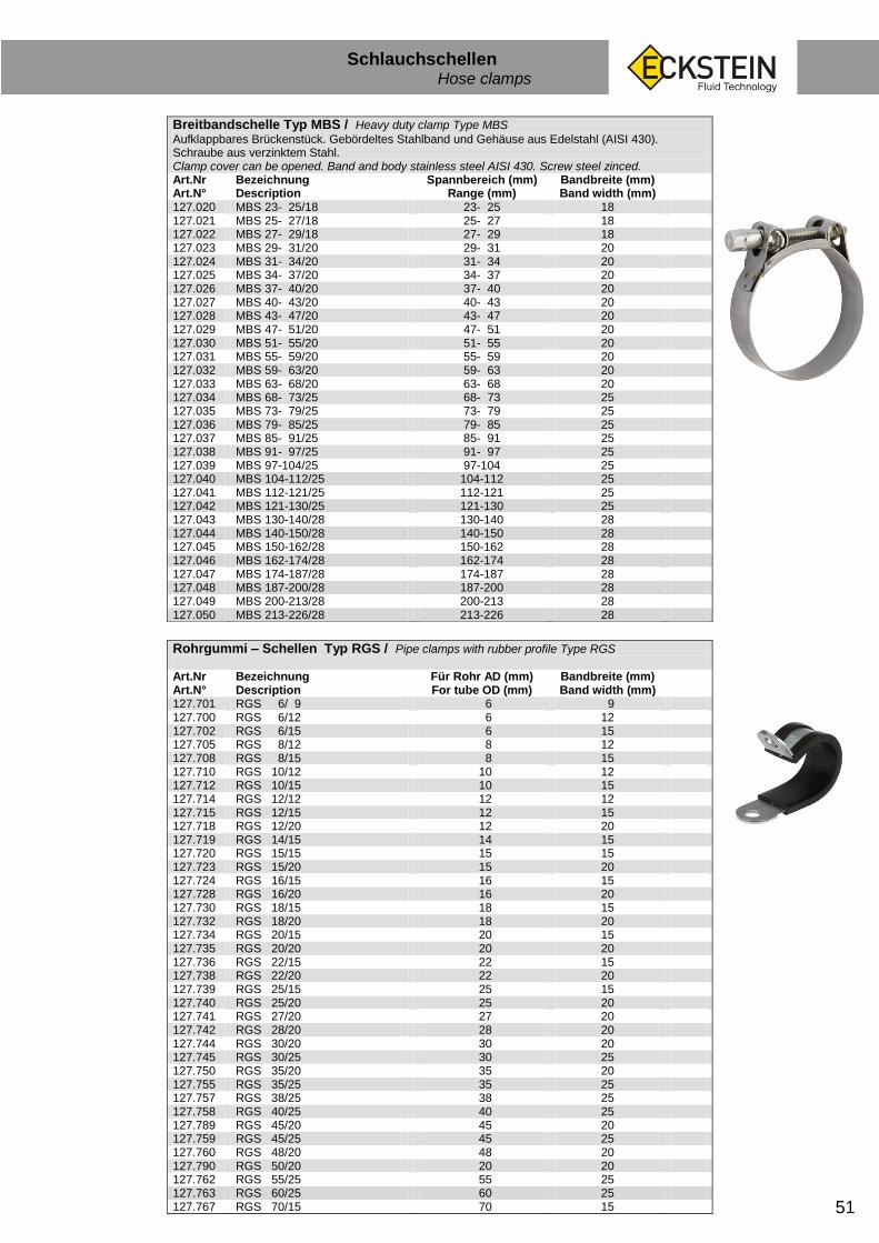
51
Schlauchschellen Hose clamps
Breitbandschelle Typ MBS / Heavy duty clamp Type MBS
Aufklappbares Brückenstück. Gebördeltes Stahlband und Gehäuse aus Edelstahl (AISI 430). Schraube aus verzinktem Stahl. Clamp cover can be opened. Band and body stainless steel AISI 430. Screw steel zinced. Art.Nr Art.N°
Bezeichnung Description
Spannbereich (mm) Range (mm)
Bandbreite (mm) Band width (mm)
127.020 MBS 23- 25/18 23- 25 18 127.021 MBS 25- 27/18 25- 27 18 127.022 MBS 27- 29/18 27- 29 18 127.023 MBS 29- 31/20 29- 31 20 127.024 MBS 31- 34/20 31- 34 20 127.025 MBS 34- 37/20 34- 37 20 127.026 MBS 37- 40/20 37- 40 20 127.027 MBS 40- 43/20 40- 43 20 127.028 MBS 43- 47/20 43- 47 20 127.029 MBS 47- 51/20 47- 51 20 127.030 MBS 51- 55/20 51- 55 20 127.031 MBS 55- 59/20 55- 59 20 127.032 MBS 59- 63/20 59- 63 20 127.033 MBS 63- 68/20 63- 68 20 127.034 MBS 68- 73/25 68- 73 25 127.035 MBS 73- 79/25 73- 79 25 127.036 MBS 79- 85/25 79- 85 25 127.037 MBS 85- 91/25 85- 91 25 127.038 MBS 91- 97/25 91- 97 25 127.039 MBS 97-104/25 97-104 25 127.040 MBS 104-112/25 104-112 25 127.041 MBS 112-121/25 112-121 25 127.042 MBS 121-130/25 121-130 25 127.043 MBS 130-140/28 130-140 28 127.044 MBS 140-150/28 140-150 28 127.045 MBS 150-162/28 150-162 28 127.046 MBS 162-174/28 162-174 28 127.047 MBS 174-187/28 174-187 28 127.048 MBS 187-200/28 187-200 28 127.049 MBS 200-213/28 200-213 28 127.050 MBS 213-226/28 213-226 28
Rohrgummi – Schellen Typ RGS / Pipe clamps with rubber profile Type RGS
Art.Nr Art.N°
Bezeichnung Description
Für Rohr AD (mm) For tube OD (mm)
Bandbreite (mm) Band width (mm)
127.701 RGS 6/ 9 6 9 127.700 RGS 6/12 6 12 127.702 RGS 6/15 6 15 127.705 RGS 8/12 8 12 127.708 RGS 8/15 8 15 127.710 RGS 10/12 10 12 127.712 RGS 10/15 10 15 127.714 RGS 12/12 12 12 127.715 RGS 12/15 12 15 127.718 RGS 12/20 12 20 127.719 RGS 14/15 14 15 127.720 RGS 15/15 15 15 127.723 RGS 15/20 15 20 127.724 RGS 16/15 16 15 127.728 RGS 16/20 16 20 127.730 RGS 18/15 18 15 127.732 RGS 18/20 18 20 127.734 RGS 20/15 20 15 127.735 RGS 20/20 20 20 127.736 RGS 22/15 22 15 127.738 RGS 22/20 22 20 127.739 RGS 25/15 25 15 127.740 RGS 25/20 25 20 127.741 RGS 27/20 27 20 127.742 RGS 28/20 28 20 127.744 RGS 30/20 30 20 127.745 RGS 30/25 30 25 127.750 RGS 35/20 35 20 127.755 RGS 35/25 35 25 127.757 RGS 38/25 38 25 127.758 RGS 40/25 40 25 127.789 RGS 45/20 45 20 127.759 RGS 45/25 45 25 127.760 RGS 48/20 48 20 127.790 RGS 50/20 20 20 127.762 RGS 55/25 55 25 127.763 RGS 60/25 60 25 127.767 RGS 70/15 70 15

52
Schlauchverbinder-PVC Hose connectors
EN 412.01 DE
Schlauchverbinder Polyamid Typ PVCG / Hose connectors of polyamide type PVCG
Für einfache, druckarme Schlauchverbindungen / For simple, low pressure connections of hoses Art.Nr Art.N°
Bezeichnung Description
für Schlauch ID (mm)
127.800 PVCG 3 3 127.801 PVCG 4 4 127.802 PVCG 5 5 127.803 PVCG 6 6 127.804 PVCG 8 8 127.805 PVCG 10 10 127.806 PVCG 12 12 127.807 PVCG 14 14 127.808 PVCG 16 16 127.809 PVCG 19 19
Winkelverbinder Polyamid Typ PVCW / Elbow-connectors of polyamide type PVCW
Für einfache, druckarme Schlauchverbindungen / For simple, low pressure connections of hoses Art.Nr Art.N°
Bezeichnung Description
für Schlauch ID (mm)
127.820 PVCW 3 3 127.821 PVCW 4 4 127.822 PVCW 5 5 127.823 PVCW 6 6 127.824 PVCW 8 8 127.825 PVCW 10 10 127.826 PVCW 12 12 127.827 PVCW 16 16 127.828 PVCW 19 19
T-Schlauchverbinder Polyamid Typ PVCT / T-connectors of polyamide type PVCT
Für einfache, druckarme Schlauchverbindungen / For simple, low pressure connections of hoses Art.Nr Art.N°
Bezeichnung Description
für Schlauch ID (mm)
127.810 PVCT 3 3 127.811 PVCT 4 4 127.812 PVCT 5 5 127.813 PVCT 6 6 127.814 PVCT 8 8 127.815 PVCT 10 10 127.816 PVCT 12 12 127.817 PVCT 16 16 127.818 PVCT 19 19
Y-Schlauchverbinder Polyamid Typ PVCY / Y-connectors of polyamide type PVCY
Für einfache, druckarme Schlauchverbindungen / For simple, low pressure connections of hoses Art.Nr Art.N°
Bezeichnung Description
für Schlauch ID (mm)
127.839 PVCY 4 4 127.840 PVCY 5 5 127.841 PVCY 6 6 127.842 PVCY 8 8 127.843 PVCY 10 10 127.844 PVCY 12 12 127.846 PVCY 16 16 127.847 PVCY 19 19
Schlauchverbinder Polyamid Typ PVCG-RED / Hose connectors of polyamide type PVCG
Für einfache, druckarme Schlauchverbindungen / For simple, low pressure connections of hoses Art.Nr Art.N°
Bezeichnung Description
für Schlauch ID A (mm)
für Schlauch ID B (mm)
127.990 PVCG-RED 4-3 4 3 127.991 PVCG-RED 6-4 6 4 127.992 PVCG-RED 8-5 8 5 127.993 PVCG-RED 8-6 8 6 127.995 PVCG-RED 10-6 10 6 127.996 PVCG-RED 10-8 10 8 127.998 PVCG-RED 12-8 12 8 127.997 PVCG-RED 12-10 12 10 127.999 PVCG-RED 14-10 14 10

53
Schlauchverbinder-Metall Hose connectors
EN 412.01 DE
Schlauchverbinder Typ GSM / Material: Stahl verzinkt. Art.Nr Art.N°
Bezeichnung Description
für Schlauch ID (mm)
127.870 GSM 4 4 127.871 GSM 6 6 127.872 GSM 8 8 127.874 GSM 10 10 127.876 GSM 12 12 127.869 GSM 15 15
Messing-Schlauchverbinder Typ MS-GSM / Art.Nr Art.N°
Bezeichnung Description
für Schlauch ID (mm)
127.880 MS-GSM 15 15 127.884 MS-GSM 20 20 127.886 MS-GSM 22 22 127.888 MS-GSM 25 25 127.889 MS-GSM 32 32 127.890 MS-GSM 38 38
Messing-Schlauchverbinder Typ MS-TSM / Art.Nr Art.N°
Bezeichnung Description
für Schlauch ID (mm)
127.838 MS-TSM 10 10 127.848 MS-TSM 13 13 124.834 MS-TSM 15 15 127.836 MS-TSM 20 20
T-Schlauchverbinder Typ TSM / Material: Stahl verzinkt. Art.Nr Art.N°
Bezeichnung Description
für Schlauch ID (mm)
127.829 TSM 4 4 127.830 TSM 6 6 127.831 TSM 8 8 127.832 TSM 10 10 127.833 TSM 12 12
Reduzier-Schlauchverbinder Typ GSM / Material: Stahl verzinkt. Art.Nr Art.N°
Bezeichnung Description
für Schlauch ID A (mm)
für Schlauch ID B (mm)
127.873 GSM 8 /6 8 6 127.875 GSM 10 /8 10 8 127.877 GSM 12 /8 12 8 127.878 GSM 12 /10 12 10 127.879 GSM 15 /12 15 12
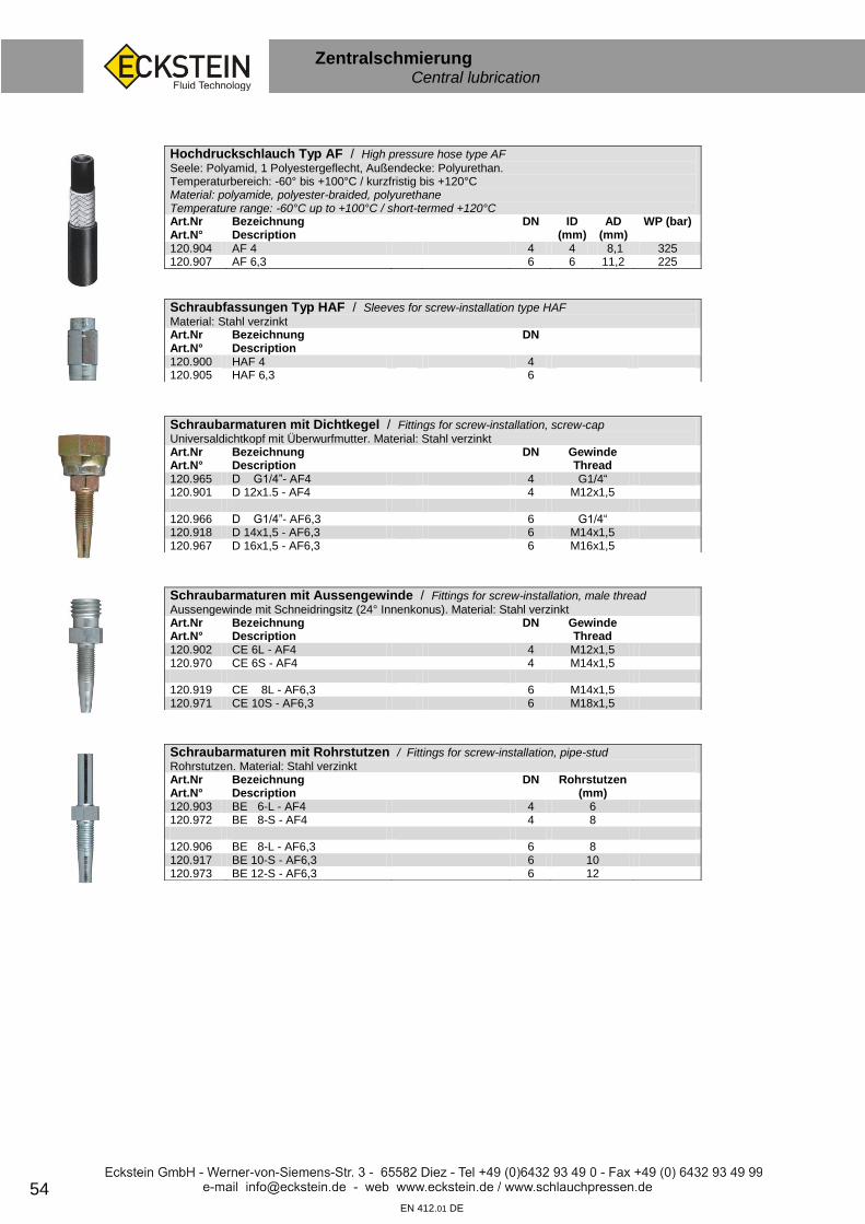
54 EN 412.01 DE
Zentralschmierung Central lubrication
Hochdruckschlauch Typ AF / High pressure hose type AF Seele: Polyamid, 1 Polyestergeflecht, Außendecke: Polyurethan. Temperaturbereich: -60° bis +100°C / kurzfristig bis +120°C Material: polyamide, polyester-braided, polyurethane Temperature range: -60°C up to +100°C / short-termed +120°C Art.Nr Art.N°
Bezeichnung Description
DN ID (mm)
AD (mm)
WP (bar)
120.904 AF 4 4 4 8,1 325 120.907 AF 6,3 6 6 11,2 225
Schraubfassungen Typ HAF / Sleeves for screw-installation type HAF
Material: Stahl verzinkt Art.Nr Art.N°
Bezeichnung Description
DN
120.900 HAF 4 4 120.905 HAF 6,3 6
Schraubarmaturen mit Dichtkegel / Fittings for screw-installation, screw-cap
Universaldichtkopf mit Überwurfmutter. Material: Stahl verzinkt Art.Nr Art.N°
Bezeichnung Description
DN Gewinde Thread
120.965 D G1/4”- AF4 4 G1/4“ 120.901 D 12x1.5 - AF4 4 M12x1,5 120.966 D G1/4”- AF6,3 6 G1/4“ 120.918 D 14x1,5 - AF6,3 6 M14x1,5 120.967 D 16x1,5 - AF6,3 6 M16x1,5
Schraubarmaturen mit Aussengewinde / Fittings for screw-installation, male thread
Aussengewinde mit Schneidringsitz (24° Innenkonus). Material: Stahl verzinkt Art.Nr Art.N°
Bezeichnung Description
DN Gewinde Thread
120.902 CE 6L - AF4 4 M12x1,5 120.970 CE 6S - AF4 4 M14x1,5 120.919 CE 8L - AF6,3 6 M14x1,5 120.971 CE 10S - AF6,3 6 M18x1,5
Schraubarmaturen mit Rohrstutzen / Fittings for screw-installation, pipe-stud Rohrstutzen. Material: Stahl verzinkt Art.Nr Art.N°
Bezeichnung Description
DN Rohrstutzen (mm)
120.903 BE 6-L - AF4 4 6 120.972 BE 8-S - AF4 4 8 120.906 BE 8-L - AF6,3 6 8 120.917 BE 10-S - AF6,3 6 10 120.973 BE 12-S - AF6,3 6 12

55 EN 412.02 DE
Zentralschmierung Central lubrication
Polyamid-Rohr Typ PAR / Polyamid pipe PA 11/12 Type PAR
Temperaturbereich -60°C bis +100°C, Farbe: natur. Angegebener Betriebsdruck bei 20°C. T° range -60°C up to +100. Color: black. Other colors on request. Indicated WP at 20°C Art.Nr Art.N°
Bezeichnung Description
AD (mm) ID (mm) WP (bar)
120.177 Z-PAR 4/1,25 4 1,5 136 120.176 Z-PAR 6/1,5 6 3 100
Überwurfschrauben Typ USZ / Hollow screws Type USZ
Material: Stahl verzinkt / galvanized steel Art.Nr Art.N°
Bezeichnung Description
für Rohr AD (mm)
Gewinde Thread
124.800 USZ 4/8 4 M 8x1,0 124.801 USZ 4/10 4 M10x1,0 124.805 USZ 5/10 5 M10x1,0 124.810 USZ 6/10 6 M10x1,5 124.820 USZ 8/14 8 M14x1,5 124.825 USZ 10/16 10 M16x1,5
Doppelkonen Typ DKN / Stuffing cones Type DKN
Messing / Brass Art.Nr Art.N°
Bezeichnung Description
für Rohr AD (mm)
PE
128.000 DKN 4 4 100 128.001 DKN 5 5 100 128.002 DKN 6 6 100 128.003 DKN 8 8 100 128.004 DKN 10 10 100
Gerade Reduzierstücke Typ RED / Straight reduction pieces Type RED
Material: Stahl verzinkt / galvanized steel Art.Nr Art.N°
Bezeichnung Description
Innengewinde
Außengewinde
128.524 RED IG 8x1 AG 6x1 M8x1 M6x1 128.520 RED IG 8x1 AG 8x1 M8x1 M8x1 128.521 RED IG 8x1 AG 10x1 M8x1 M10x1 128.527 RED IG 8x1 AG R1/8“ M8x1 R1/8“ 128.522 RED IG 10x1 AG 8x1 M10x1 M8x1 128.523 RED IG 10x1 AG 10x1 M10x1 M10x1 128.528 RED IG 10x1 AG R1/8“ M10x1 R1/8“
Winkelstücke 90° Typ W IG.. AG.. / Reduction pieces 90° Type W IG.. AG..
Material: Messing / Brass Art.Nr Art.N°
Bezeichnung Description
Innengewinde
Außengewinde
128.539 W IG 8x1 AG 6x1 M8x1 M6x1 128.540 W IG 8x1 AG 8x1 M8x1 M8x1 128.541 W IG 8x1 AG 10x1 M8x1 M10x1 128.544 W IG 8x1 AG R1/8“ M8x1 R1/8“ 128.542 W IG 10x1 AG 10x1 M10x1 M10x1

56
Zentralschmierung Central lubrication
EN 412.01 DE
Einschraub-Steckverbinder Zentralschmierung Typ Z-EPDVS Male stud connector central lubrication type Z-EPDVS Werkstoff: Messing vernickelt, Betriebsdruck: max. 65 bar, Betriebstemperatur: -20°C bis +120°C Material: Brass nickeled, WP max. 65 bar, Work. T° -20°C up to +120°C Art.Nr Art.N°
Bezeichnung Description
für Rohr AD (mm) for Tube OD (mm)
Einschraubgewinde Thread
128.600 Z-EPDVS M 6x1 R-4 4 M 6x1 128.601 Z-EPDVS M 8x1 R-4 4 M 8x1 128.602 Z-EPDVS M 10x1 R-4 4 M10x1 128.603 Z-EPDVS G1/8” R-4 4 G1/8” 128.604 Z-EPDVS G1/4” R-4 4 G1/4” 128.610 Z-EPDVS M 6x1 R- 6 6 M 6x1 128.611 Z-EPDVS M 8x1 R- 6 6 M 8x1 128.612 Z-EPDVS M 10x1 R- 6 6 M10x1 128.613 Z-EPDVS G1/8” R- 6 6 G1/8” 128.614 Z-EPDVS G1/4” R- 6 6 G1/4”
Winkel-Einschraub-Steckverbinder Zentralschmierung Typ Z-EWPDVS Elbow- Male stud connector central lubrication type Z-EWPDVS Werkstoff: Messing vernickelt, Betriebsdruck: max. 65 bar, Betriebstemperatur: -20°C bis +120°C Material: Brass nickeled, WP max. 65 bar, Work. T° -20°C up to +120°C Art.Nr Art.N°
Bezeichnung Description
für Rohr AD (mm) for Tube OD (mm)
Einschraubgewinde Thread
128.630 Z-EWPDVS M 6x1 R-4 4 M 6x1 128.631 Z-EWPDVS M 8x1 R-4 4 M 8x1 128.632 Z-EWPDVS M 10x1 R-4 4 M10x1 128.633 Z-EWPDVS G1/8” R-4 4 G1/8” 128.640 Z-EWPDVS M 6x1 R- 6 6 M 6x1 128.641 Z-EWPDVS M 8x1 R- 6 6 M 8x1 128.642 Z-EWPDVS M 10x1 R- 6 6 M10x1 128.643 Z-EWPDVS G1/8” R- 6 6 G1/8” 128.644 Z-EWPDVS G1/4” R- 6 6 G1/4”
Steckverbinder Zentralschmierung Typ Z-PDVS Werkstoff: Messing vernickelt, Betriebsdruck: max. 65 bar, Betriebstemperatur: -20°C bis +120°C Material: Brass nickeled, WP max. 65 bar, Work. T° -20°C up to +120°C Art.Nr Art.N°
Bezeichnung Description
für Rohr AD (mm) for Tube OD (mm)
128.650 Z-PDVS 4 4 128.651 Z-PDVS 6 6 128.652 Z-PDVS 8 8
Winkel-Steckverbinder f. PA-Rohr Typ Z-PWVS/ Werkstoff: Messing vernickelt, Betriebsdruck: max. 65 bar, Betriebstemperatur: -20°C bis +120°C Material: Brass nickeled, WP max. 65 bar, Work. T° -20°C up to +120°C Art.Nr Art.N°
Bezeichnung Description
für Rohr AD (mm) for Tube OD (mm)
128.660 Z-PWVS 4 4 128.661 Z-PWVS 6 6 128.662 Z-PWVS 8 8
T-Steckverbinder f. PA-Rohr Typ Z-PTVS Werkstoff: Messing vernickelt, Betriebsdruck: max. 65 bar, Betriebstemperatur: -20°C bis +120°C Material: Brass nickeled, WP max. 65 bar, Work. T° -20°C up to +120°C Art.Nr Art.N°
Bezeichnung Description
für Rohr AD (mm) for Tube OD (mm)
128.670 Z-PTVS 4 4 128.671 Z-PTVS 6 6 128.672 Z-PTVS 8 8

57 EN 412.01 DE
Schmiernippel Grease nipple
Schmiernippel Typ SM.. A / Grease nipple type SM.. A
gerade / straight Art.Nr Art.N°
Bezeichnung Description
Gewinde Thread
129.506 SM 6 A M 6x1 129.508 SM 8 A M 8x1 129.510 SM 10 A M 10x1 129.518 SM 18 A G 1/8“ 129.514 SM 14 A G 1/4“
Schmiernippel Typ SM.. B / Grease nipple type SM.. B
45° Art.Nr Art.N°
Bezeichnung Description
Gewinde Thread
129.536 SM 6 B M 6x1 129.538 SM 8 B M 8x1 129.540 SM 10 B M 10x1 129.548 SM 18 B G 1/8“ 129.544 SM 14 B G 1/4“
Schmiernippel Typ SM.. C / Grease nipple type SM.. C
90° Art.Nr Art.N°
Bezeichnung Description
Gewinde Thread
129.566 SM 6 C M 6x1 129.568 SM 8 C M 8x1 129.570 SM 10 C M 10x1 129.578 SM 18 C G 1/8“ 129.574 SM 14 C G 1/4“
Zubehör für Fettpressen / Accessory for lubrication machine Art.Nr Art.N°
Bezeichnung Description
Gewinde Thread
Länge (mm)
129.600 Universal Mundstück Abschmierkopf mit 4 Backen Lubrication head with 4 dies
M 10x1
129.630 Abschmierschlauch 300 Lubrication hose 300
300
129.650 Abschmierschlauch 500 Lubrication hose 500
500
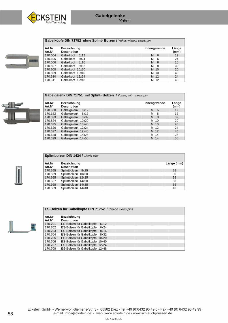
58 EN 412.01 DE
Gabelgelenke Yokes
Gabelköpfe DIN 71752 ohne Splint- Bolzen / Yokes without clevis pin
Art.Nr Art.N°
Bezeichnung Description
Innengewinde
Länge (mm)
170.604 Gabelkopf 6x12 M 6 12 170.605 Gabelkopf 6x24 M 6 24 170.606 Gabelkopf 8x16 M 8 16 170.607 Gabelkopf 8x32 M 8 32 170.608 Gabelkopf 10x20 M 10 20 170.609 Gabelkopf 10x40 M 10 40 170.610 Gabelkopf 12x24 M 12 24 170.611 Gabelkopf 12x48 M 12 48
Gabelgelenk DIN 71751 mit Splint- Bolzen / Yokes, with clevis pin
Art.Nr. Art.N°
Bezeichnung Description
Innengewinde
Länge (mm)
170.620 Gabelgelenk 6x12 M 6 12 170.622 Gabelgelenk 8x16 M 8 16 170.623 Gabelgelenk 8x32 M 8 32 170.624 Gabelgelenk 10x20 M 10 20 170.625 Gabelgelenk 10x40 M 10 40 170.626 Gabelgelenk 12x24 M 12 24 170.627 Gabelgelenk 12x48 M 12 48 170.628 Gabelgelenk 14x28 M 14 28 170.629 Gabelgelenk 14x56 M 14 56
Splintbolzen DIN 1434 / Clevis pins
Art.Nr Art.N°
Bezeichnung Description
Länge (mm)
170.655 Splintbolzen 8x25 25 170.659 Splintbolzen 10x30 30 170.665 Splintbolzen 12x35 35 170.667 Splintbolzen 14x30 30 170.668 Splintbolzen 14x35 35 170.669 Splintbolzen 14x40 40
ES-Bolzen für Gabelköpfe DIN 71752 / Clip-on clevis pins
Art.Nr Art.N°
Bezeichnung Description
170.701 ES-Bolzen für Gabelköpfe 6x12 170.702 ES-Bolzen für Gabelköpfe 6x24 170.703 ES-Bolzen für Gabelköpfe 8x16 170.704 ES-Bolzen für Gabelköpfe 8x32 170.705 ES-Bolzen für Gabelköpfe 10x20 170.706 ES-Bolzen für Gabelköpfe 10x40 170.707 ES-Bolzen für Gabelköpfe 12x24 170.708 ES-Bolzen für Gabelköpfe 12x48

59
Winkelgelenke Angle joints
EN 412.01 DE
Winkelgelenke DIN 71 802 Typ WGL / Angle joints DIN 71802 Type WGL
Mit Sicherheitsbügel / With security clip Art.Nr Art.N°
Bezeichnung Description
Gewinde Thread
129.000 WGL M 5 M 5 129.001 WGL M 6 M 6 129.002 WGL M 6 L M 6 L L = Linksgewinde / Left thread 129.003 WGL M 6 LG M 6 LG = Lange Kugelpfanne 40 mm 129.005 WGL M 8 M 8 / Long ball socket 40 mm 129.006 WGL M 8 L M 8 L 129.007 WGL M 8 LG M 8 129.010 WGL M 10 M 10 129.012 WGL M 12 M 12 129.014 WGL M 14 M 14 129.016 WGL M 16 M 16
Sicherungsbügel für Winkelgelenke Typ SI / Security clip for angle joints Type SI
Art.Nr Art.N°
Bezeichnung Description
Für Winkelgelenke For angle joints
129.200 SI M 5 WGL M 5 129.201 SI M 6 WGL M 6 129.206 SI M 8 WGL M 8 129.210 SI M 10 + 12 WGL M 10 + 12 129.214 SI M 14 WGL M 14
Winkelgelenke mit PVC-Einsatz Typ WGL-P / Angle joints with PVC-liner Type WGL
Wartungsfrei / No maintenance required Art.Nr Art.N°
Bezeichnung Description
Gewinde Thread
129.300 WGL M 5 P M 5 129.301 WGL M 6 P M 6 129.302 WGL M 6 P L M 6 L L = Linksgewinde / Left thread 129.303 WGL M 6 P LG M 6 LG = Lange Kugelpfanne 40 mm 129.305 WGL M 8 P M 8 / Long ball socket 40 mm 129.306 WGL M 8 P L M 8 L 129.310 WGL M 10 P M 10 129.311 WGL M 10 P L M 10 L
Kugelpfanne Typ KP / Ball socket Type KP
Art.Nr Art.N°
Bezeichnung Description
Gewinde Thread
Für Winkelgelenke For angle joints
129.120 KP M 5 M 5 WGL M 5 129.121 KP M 6 M 6 WGL M 6 129.126 KP M 8 M 8 WGL M 8 129.130 KP M 10 M 10 WGL M 10 129.132 KP M 12 M 12 WGL M 12 129.134 KP M 14 M 14 WGL M 14
Kugelbolzen Typ BZ / Ball plug Type BZ
Art.Nr Art.N°
Bezeichnung Description
Gewinde Thread
Für Winkelgelenke For angle joints
129.100 BZ M 5 M 5 WGL M 5 129.101 BZ M 6 M 6 WGL M 6 129.106 BZ M 8 M 8 WGL M 8 129.110 BZ M 10 M 10 WGL M 10 129.112 BZ M 12 M 12 WGL M 12 129.114 BZ M 14 M 14 WGL M 14

60 EN 412.01 DE
Bremsleitung Brake tube
Bremsleitungsrohr Typ SRO / Hydraulic brake tube Type SRO
Oberfläche: kunststoffbeschichtet Art.Nr Art.N°
Bezeichnung Description
Länge (m)
124.900 SRO 4,75 x 0,7 5 124.902 SRO 6,00 x 0,7 5 124.901 SRO 4,75 x 0,7 32 124.903 SRO 6,00 x 0,7 32
Überwurfschrauben Typ USB / Hollow screws Type USB
Für Bremsleitungen. F=flach; E=Innenkonus / For hydraulic brakes Art.Nr Art.N°
Bezeichnung Description
für Rohr AD (mm)
Gewinde Thread
124.850 USB 4/10 F 4,75 M 10x1 124.851 USB 4/10-20 F L=20 4,75 M 10x1 124.852 USB 4/12 F 4,75 M 12x1 124.855 USB 4/10 E 4,75 M 10x1 124.853 USB 4/12 E 4,75 M 12x1 124.858 USB 4/10x1,25 L=15 4,75 M 10x1,25 124.859 USB 4/10x1,25 L=20 4,75 M 10x1,25 124.857 USB 4/10x1,25 L=25 4,75 M 10x1,25 124.860 USB 6/12 F 6 M 12x1 124.865 USB 6/12 E 6 M 12x1 124.871 USB 8/14 F 8 M 14x1,5 124.879 USB 4/ 3/8” 4,75 UNF 3/8“-24 124.878 USB 6/ 7/16” 6 UNF 7/16”-20
Überwurfmutter Typ UMB / Screw caps type UMB Für Bremsleitungen / For hydraulic brakes Art.Nr Art.N°
Bezeichnung Description
für Rohr AD (mm)
Gewinde Thread
124.849 UMB 4/10 4,75 M 10x1
Verbindungsstück für Bremsrohre Typ DSTB / Connector for brake tubes Type DSTB
Art.Nr Art.N°
Bezeichnung Description
für Rohr AD (mm)
Gewinde Thread
124.880 DSTB 10 F 4,75 M 10x1 124.882 DSTB 12 E 6 M 12x1
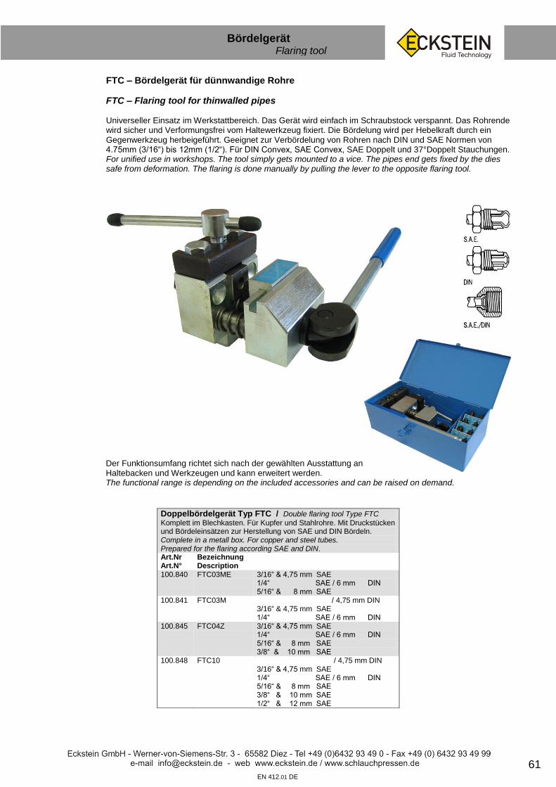
61 EN 412.01 DE
Bördelgerät Flaring tool
Der Funktionsumfang richtet sich nach der gewählten Ausstattung an Haltebacken und Werkzeugen und kann erweitert werden. The functional range is depending on the included accessories and can be raised on demand.
FTC – Bördelgerät für dünnwandige Rohre
FTC – Flaring tool for thinwalled pipes
Universeller Einsatz im Werkstattbereich. Das Gerät wird einfach im Schraubstock verspannt. Das Rohrende wird sicher und Verformungsfrei vom Haltewerkzeug fixiert. Die Bördelung wird per Hebelkraft durch ein Gegenwerkzeug herbeigeführt. Geeignet zur Verbördelung von Rohren nach DIN und SAE Normen von 4.75mm (3/16“) bis 12mm (1/2“). Für DIN Convex, SAE Convex, SAE Doppelt und 37°Doppelt Stauchungen. For unified use in workshops. The tool simply gets mounted to a vice. The pipes end gets fixed by the dies safe from deformation. The flaring is done manually by pulling the lever to the opposite flaring tool.
Doppelbördelgerät Typ FTC / Double flaring tool Type FTC
Komplett im Blechkasten. Für Kupfer und Stahlrohre. Mit Druckstücken und Bördeleinsätzen zur Herstellung von SAE und DIN Bördeln. Complete in a metall box. For copper and steel tubes. Prepared for the flaring according SAE and DIN. Art.Nr Art.N°
Bezeichnung Description
100.840 FTC03ME 3/16“ & 4,75 mm SAE 1/4“ SAE / 6 mm DIN 5/16“ & 8 mm SAE
100.841 FTC03M / 4,75 mm DIN 3/16“ & 4,75 mm SAE 1/4“ SAE / 6 mm DIN
100.845 FTC04Z 3/16“ & 4,75 mm SAE 1/4“ SAE / 6 mm DIN 5/16“ & 8 mm SAE 3/8“ & 10 mm SAE
100.848 FTC10 / 4,75 mm DIN 3/16“ & 4,75 mm SAE 1/4“ SAE / 6 mm DIN 5/16“ & 8 mm SAE 3/8“ & 10 mm SAE 1/2“ & 12 mm SAE

62
Diesel Einspritzleitung Injection line
EN 412.01 DE
Lötnippel für Diesel-Einspritzleitungen Typ DELN Solding nipple for injection lines Type DELN Art.Nr Art.N°
Bezeichnung Description
für Überwurfmutter fits with screw cap
für Rohr AD (mm)
123.022 DELN 12 M 12x1,5 6 123.024 DELN 14 M 14x1,5 6
Überwurfmutter für Diesel-Einspritzleitungen Typ DEUM Screw caps for injection lines Type DEUM Art.Nr Art.N°
Bezeichnung Description
Gewinde Thread
für Rohr AD (mm)
123.042 DEUM 12 M 12x1,5 6 123.044 DEUM 14 M 14x1,5 6
Diesel-Schnellverbinder Typ DES / Quick connection nut Type DES
Art.Nr Art.N°
Bezeichnung Description
Gewinde Thread
für Rohr AD (mm)
123.012 DES 12 M 12x1,5 6 123.014 DES 14 M 14x1,5 6
Diesel-Einspritzrohr Typ DER / Diesel injection pipe Type DER
Oberfläche: verzinkt. Länge 6m Art.Nr Art.N°
Bezeichnung Description
123.000 DER 6/1,5 123.002 DER 6/2

63 EN 412.01 DE
Sortimente Assortments
Startpaket UPS / Starter kit UPS
Art.Nr Art.N°
Bezeichnung Description
100.345 UPS 1 30 m Kraftstoffschlauch 200 Hülsen 80 Schlauchnippel 80 Überwurfmuttern 50 Außengewindenippel 100 Ringschlauchnippel 10 Doppelringschlauchnippel 40 Hohlschrauben
UPS 1 30 m fuel hose 200 sleeves 80 hose nipples 80 screw caps 50 male thread nipples 100 banjo nipples 10 twin banjo nipples 40 hollow screws
Startpaket UPJ / Starter kit UPJ
Art.Nr Art.N°
Bezeichnung Description
100.342 UPJ 2 30 m Kraftstoffschlauch 120 Hülsen 40 Schlauchnippel 40 Überwurfmuttern 40 Außengewindenippel 30 Ringschlauchnippel 28 Hohlschrauben 16 Rohrstutzen
UPJ 2 30 m fuel hose 120 sleeves 40 hose nipples 40 screw caps 40 male thread nipples 30 banjo nipples 28 hollow screws 16 pipe nipples
FTC03ME Bördelgerät / FTC03ME flaring tool
Art.Nr Art.N°
Bezeichnung Description
100.842 FTC00 Bördelgerät Klemmbacken SAE3/16“ + DIN 4,75 mm Druckwerkzeuge SAE3/16“ + DIN 4,75 mm Klemmbacken SAE1/4“ + DIN 6,0 mm Druckwerkzeuge SAE1/4“ + DIN 6,0 mm 80 Überwurfschrauben 8 Verbindungsstücke
FTC00 flaring tool Dieset SAE3/16“ + DIN 4.75 mm Punch SAE3/16“ + DIN 4.75 mm Dieset SAE1/4“ + DIN 6.0 mm Punch SAE1/4“ + DIN 6.0 mm 80 8 connectors
Sortiment A / Schlauch + Armaturen DN4-8 / Hose + fittings DN4-8 Art.Nr Art.N°
Bezeichnung Description
100.910 30 m Kraftstoffschlauch (ID 6+8+10) 200 Hülsen 80 Schlauchnippel 80 Überwurfmuttern 50 Außengewindenippel 100 Ringschlauchnippel 10 Doppelringschlauchnippel 40 Hohlschrauben
30 m fuel hose 200 sleeves 80 hose nipples 80 screw caps 50 male thread nipples 100 banjo nipples 10 twin banjo nipples 40 hollow screws
Sortiment B / Schlauch + Armaturen DN10-12 / Hose + fittings DN10-12 Art.Nr Art.N°
Bezeichnung Description
100.911 10 m Kraftstoffschlauch (ID 12+15) 60 Hülsen 30 Schlauchnippel 25 Überwurfmuttern 25 Außengewindenippel 11 Ringschlauchnippel 20 Rohrstutzen 7 Hohlschrauben
10 m fuel hose 60 sleeves 30 hose nipples 25 screw caps 25 male thread nipples 11 banjo nipples 20 pipe studs 7 hollow screws

64 EN 412.01 DE
Sortimente Assortments
Sortiment Schlauchhülsen / Sleeves
595 Stk. Schlauchhülsen Art.Nr Art.N°
Bezeichnung Description
100.912 50 H 4/9 50 H 5/10 50 H 5/11 50 H 6/11 30 H 6/12 25 H 6/13,5 50 H 8/13,5 30 H 8/14 25 H 8/15 25 H 10/15
50 H 10/16 20 H 10/17 18 H 12/18 24 H 12/19 12 H 12/20 16 H 12/22 16 H 15/23 24 H 15/24,5 12 H 18/26,5 18 H 18/28
Sortiment Edelstahl-Schlauchhülsen / Stainless sleeves
295 Stk. Edelstahl-Schlauchhülsen Art.Nr Art.N°
Bezeichnung Description
100.959 20 VA-H 4/9 20 VA-H 5/10 20 VA-H 6/11 20 VA-H 6/12 20 VA-H 8/13,5 20 VA-H 8/14 20 VA-H 10/15 20 VA-H 10/16
20 VA-H 10/17 20 VA-H 12/18 20 VA-H 12/19 20 VA-H 12/20 20 VA-H 12/22 20 VA-H 15/23 10 VA-H 15/24,5 5 VA-H 18/26,5
Sortiment Kupferdichtungen metrisch KD1 / Copper gaskets
1.565 Stk. Kupferdichtungen Art.Nr Art.N°
Bezeichnung Description
100.914
100 KD 6/10 100 KD 8/11 100 KD 8/14 100 KD 10/14 100 KD 10/16 100 KD 12/16 100 KD 12/18 100 KD 14/18 100 KD 14/20 100 KD 15/19 100 KD 16/22 50 KD 18/24 50 KD 20/26 50 KD 22/29
50 KD 24/32 25 KD 26/32 25 KD 28/36 25 KD 30/38 25 KD 32/38 25 KD 33/39 25 KD 35/41 25 KD 36/42 25 KD 40/47 25 KD 42/49 10 KD 45/52 10 KD 48/55 10 KD 50/57 10 KD 60/68
Sortiment Kupferdichtungen metrisch KD2 / Copper gaskets
450 Stk. Kupferdichtungen Art.Nr Art.N°
Bezeichnung Description
100.920
50 KD 6/10 50 KD 8/11 50 KD 10/14 50 KD 12/16 50 KD 14/18 50 KD 16/20
25 KD 18/22 25 KD 20/26 25 KD 22/27 25 KD 24/30 25 KD 26/32 25 KD 30/36
Sortiment Kupferdichtungen zöllig KD3 / Copper gaskets
220 Stk. Kupferdichtungen Art.Nr Art.N°
Bezeichnung Description
100.921 30 KD 10/14 = 1/8“ 30 KD 13/18 = 1/4“ 30 KD 17/21 = 3/8“ 30 KD 21/26 = 1/2“
30 KD 27/32 = 3/4“ 30 KD 33/39 = 1“ 20 KD 42/49 = 1 1/4“ 20 KD 48/55 = 1 1/2“

65 EN 412.01 DE
Sortimente Assortments
Sortiment Kupferdichtungen KD4 / Copper gaskets
1.325 Stk. Kupferdichtungen Art.Nr Art.N°
Bezeichnung Description
100.936
100 KD 6/10 100 KD 6/12 100 KD 8/12 100 KD 8/14 100 KD 10/14 = 1/8“ 100 KD 10/16 = 1/8“ 100 KD 12/16 100 KD 12/18 100 KD 14/18
100 KD 14/20 50 KD 16/20 50 KD 16/22 50 KD 18/24 50 KD 20/26 50 KD 22/27 25 KD 24/32 25 KD 26/32 25 KD 30/36 = 7/8“
Sortiment USIT Dichtungen metrisch DSMZ-Mini / Usit gaskets
40 Stk. Dichtungen mit Zentrierhilfe Art.Nr Art.N°
Bezeichnung Description
100.951
5 DSMZ 12 5 DSMZ 14 5 DSMZ 16 5 DSMZ 18
5 DSMZ 20 5 DSMZ 22 5 DSMZ 24 5 DSMZ 26
Sortiment USIT Dichtungen zöllig DSRZ-Mini / Usit gaskets
35 Stk. Dichtungen mit Zentrierhilfe Art.Nr Art.N°
Bezeichnung Description
100.952
5 DSRZ 1/8“ 5 DSRZ 1/4“ 5 DSRZ 3/8“ 5 DSRZ 1/2“
5 DSRZ 5/8“ 5 DSRZ 3/4“ 5 DSRZ 1“
Sortiment USIT Dichtungen metrisch/zöllig USIT 1 / Usit gaskets
145 Stk. Dichtungen Art.Nr Art.N°
Bezeichnung Description
100.918
10 DSM 8 10 DSM 10 10 DSM 12 10 DSM 14 10 DSM 16 10 DSM 18 10 DSM 20 10 DSM 22 10 DSM 24 5 DSM 26
10 DSR 1/8“ 10 DSR 1/4“ 10 DSR 3/8“ 10 DSR 1/2“ 5 DSR 3/4“ 5 DSR 1“
Sortiment USIT Dichtungen metrisch/zöllig USIT 2 / Usit gaskets
145 Stk. Dichtungen mit Zentrierhilfe Art.Nr Art.N°
Bezeichnung Description
100.918
10 DSMZ 8 10 DSMZ 10 10 DSMZ 12 10 DSMZ 14 10 DSMZ 16 10 DSMZ 18 10 DSMZ 20 10 DSMZ 22 10 DSMZ 24 5 DSMZ 26
10 DSRZ 1/8“ 10 DSRZ 1/4“ 10 DSRZ 3/8“ 10 DSRZ 1/2“ 5 DSRZ 3/4“ 5 DSRZ 1“

66 EN 412.01 DE
Sortimente Assortments
Sortiment Steckverbinder / Plug connector
32 Stk. PA-Rohr Verbinder Art.Nr Art.N°
Bezeichnung Description
100.938 2 PDVSO 4 4 PDVSO 6 4 PDVSO 8 4 PDVSO 10 2 PDVSO 12
2 PDVSO-RED 4-6 4 PDVSO-RED 6-8 2 PDVSO-RED 6-10 4 PDVSO-RED 8-10 2 PDVSO-RED 8-12 2 PDVSO-RED 10-12
Sortiment Kunststoff Steckverbinder / Plug connector
60 Stk. PA-Rohr Verbinder Art.Nr Art.N°
Bezeichnung Description
100.977 5 GST 4 5 GST 6 5 GST 8 5 GST 10 5 WST 4 5 WST 6
5 WST 8 5 WST 10 5 TST 4 5 TST 6 5 TST 8 5 TST 10
Sortiment Verstärkungshülsen für PA-Rohr / Polyamide sleeves 395 Stk. Art.Nr Art.N°
Bezeichnung Description
100.916 50 VHP 4/1 50 VHP 6/1 50 VHP 8/1 50 VHP 8/1,5 50 VHP 10/1 25 VHP 10/1,25
25 VHP 10/1,5 25 VHP 11/1,5 25 VHP 12/1,5 25 VHP 15/1,5 10 VHP 15/2 10 VHP 18/2
Sortiment PA-Rohr Armaturen / Polyamide fittings
175 Stk. PA-Rohr Armaturen Art.Nr Art.N°
Bezeichnung Description
100.915 10 SP 4/10 10 SP 4/12 10 SP 5/12 10 SP 5/14 10 SP 6/14 10 SP 6/16 10 SP 8/14 10 SP 8/16 10 SP 10/16
5 RSP 3/8 5 RSP 4/8 5 RSP 4/10 5 RSP 4/12 5 RSP 4/14 5 RSP 4/16 5 RSP 5/10 5 RSP 5/12 5 RSP 6/10 5 RSP 6/12 5 RSP 6/14 5 RSP 6/16 5 RSP 8/12 5 RSP 8/14 5 RSP 8/16 5 RSP 10/14 5 RSP 10/16

67 EN 412.01 DE
Sortimente Assortments
Sortiment PVC-Verbinder / Hose connectors
150 Stk. Schlauchverbinder Art.Nr Art.N°
Bezeichnung Description
100.927 10 PVCG 4 10 PVCG 5 10 PVCG 6 5 PVCG 8 5 PVCG 10 10 PVCW 4 10 PVCW 5 10 PVCW 6 5 PVCW 8 5 PVCW 10
10 PVCT 4 10 PVCT 5 10 PVCT 6 5 PVCT 8 10 PVCY 4 10 PVCY 5 10 PVCY 6 5 PVCY 8
Sortiment Schlauchschellen / Hose clamps
65 Stk. Schlauchschellen Art.Nr Art.N°
Bezeichnung Description
100.955 10 SGL 7-11/5 10 SGL 10-16/9 10 SGL 12-22/9 10 SGL 16-25/9
10 SGL 20-32/9 5 SGL 25-40/9 5 SGL 35-50/9 5 SGL 40-60/9
Sortiment Schmiernippel / Grease nipples
180 Stk. Schmiernippel Art.Nr Art.N°
Bezeichnung Description
100.940 20 SM 6 A 20 SM 8 A 20 SM 10 A 10 SM 14 A 10 SM 18 A 10 SM 6 B 10 SM 8 B 10 SM 10 B 10 SM 14 B 10 SM 18 B
10 SM 6 C 10 SM 8 C 10 SM 10 C 10 SM 14 C 10 SM 18 C

68 EN 412.01 DE
Verschlussstopfen Drain plugs
Gummi- Verschlussstopfen Typ NR-VS / Rubber-drain-plugs type NR-VS nach DIN 12871 - Material Naturkautschuk (NR) grau - Härte 40 Shore A Material: rubber (NR) Grey-Hardness 40 shore Art.Nr Art.N°
Bezeichnung Description
D1 mm
D2 mm
124.480 NR-VS 3,5- 6,5 3,5 6,5 124.481 NR-VS 5,0- 9,0 5,0 9,0 124.482 NR-VS 8,0-12,0 8,0 12,0 124.483 NR-VS 10,5-14,5 10,5 14,5 124.484 NR-VS 14,0-18,0 14,0 18,0 124.485 NR-VS 17,0-22,0 17,0 22,0 124.486 NR-VS 21,0-27,0 21,0 27,0 124.487 NR-VS 26,0-32,0 26,0 32,0 124.488 NR-VS 31,0-38,0 31,0 38,0 124.489 NR-VS 36,0-44,0 36,0 44,0 124.495 NR-VS 41,0-49,0 41,0 49,0 124.496 NR-VS 47,0-55,0 47,0 55,0 124.497 NR-VS 50,5-59,5 50,5 59,5 124,498 NR-VS 56,0-65,0 56,0 65,0 124,499 NR-VS 60,0-70,0 60,0 70,0 124,500 NR-VS 64,5-75,5 64,5 75,5 124.501 NR-VS 71,0-83,0 71,0 83,0
Sortiment NR-VS 2 / Assortment NR-VS 2 Art.-Nr. 124.491 121 tlg. / parts Menge
Art.-Nr. Art.-N°
Bezeichnung Description
20x 124.480 NR-VS 3,5- 6,5 20x 124.481 NR-VS 5,0- 9,0 20x 124.482 NR-VS 8,0-12,0 20x 124.483 NR-VS 10,5-14,5 10x 124.484 NR-VS 14,0-18,0 10x 124.485 NR-VS 17,0-22,0 10x 124.486 NR-VS 21,0-27,0 10x 124.487 NR-VS 26,0-32,0 1x 100.902 HKK 12
Sortiment NR-VS 1 / Assortment NR-VS 1 Art.-Nr. 124.490 80 tlg. / parts Menge
Art.-Nr. Art.-N°
Bezeichnung Description
10x 124.480 NR-VS 3,5- 6,5 10x 124.481 NR-VS 5,0- 9,0 10x 124.482 NR-VS 8,0-12,0 10x 124.483 NR-VS 10,5-14,5 10x 124.484 NR-VS 14,0-18,0 10x 124.485 NR-VS 17,0-22,0 5x 124.486 NR-VS 21,0-27,0 5x 124.487 NR-VS 26,0-32,0 5x 124.488 NR-VS 31,0-38,0 4x 124.489 NR-VS 36,0-44,0 1x 100.902 HKK 12

69 EN 412.01 DE
Verschlussstopfen Drain plugs
Kunststoff Gewindestopfen Typ PE-GS / Plastic threaded plugs type PE-GS Für Innengewinde bzw. Überwurfmutterarmaturen. Material: Kunststoff (PE) For inside thread‚ Nuts fittings. Material: Plastic (PE) Art.Nr Art.N°
Bezeichnung Description
141.050 PE-GS AG 1/8“ 141.051 PE-GS AG 1/4“ 141.052 PE-GS AG 3/8“ 141.053 PE-GS AG 1/2“ 141.054 PE-GS AG 3/4“ 141.055 PE-GS AG 1“ 141.065 PE-GS AG 10x1,0 141.066 PE-GS AG 12x1,5 141.067 PE-GS AG 14x1,5 141.068 PE-GS AG 16x1,5 141.069 PE-GS AG 18x1,5 141.070 PE-GS AG 20x1,5 141.071 PE-GS AG 22x1,5 141.072 PE-GS AG 24x1,5 141.073 PE-GS AG 26x1,5 141.078 PE-GS AG 30x2,0 141.080 PE-GS AG 36x2,0 141.081 PE-GS AG 42x2,0 141.082 PE-GS AG 45x2,0 141.083 PE-GS AG 52x2,0
Kunststoff Gewindekappen Typ PE-GK / Plastic thread caps type PE-GK Für Außengewinde. Material: Kunststoff (PE) For outside thread. Material plastic (EP) Art.Nr Art.N°
Bezeichnung Description
141.100 PE-GK IG 1/8“ 141.101 PE-GK IG 1/4“ 141.102 PE-GK IG 3/8“ 141.103 PE-GK IG 1/2“ 141.105 PE-GK IG 3/4“ 141.106 PE-GK IG 1“ 141.116 PE-GK IG 10x1,0 141.118 PE-GK IG 12x1,5 141.119 PE-GK IG 14x1,5 141.120 PE-GK IG 16x1,5 141.121 PE-GK IG 18x1,5 141.122 PE-GK IG 20x1,5 141.123 PE-GK IG 22x1,5 141.124 PE-GK IG 24x1,5 141.125 PE-GK IG 26x1,5 141.128 PE-GK IG 30x2,0 141.130 PE-GK IG 36x2,0 141.131 PE-GS IG 42x2,0 141.133 PE-GS IG 45x2,0 141.134 PE-GS IG 52x2,0
Kunststoff Schutzkappen Typ PE-SK / Plastic protection caps Material: Kunststoff (PE) Material: Plastic (PE) Art.Nr Art.N°
Bezeichnung Description
141.000 PE-SK ID 4,0 141.002 PE-SK ID 6,0 141.005 PE-SK ID 8,0 141.007 PE-SK ID 10,2 141.009 PE-SK ID 12,0 141.014 PE-SK ID 15,0 141.017 PE-SK ID 18,0 141.019 PE-SK ID 20,0 141.021 PE-SK ID 22,0 141.025 PE-SK ID 25,4 141.031 PE-SK ID 30,0

70 EN 412.01 DE
Werkzeug Tools
Schlauchschere / Hose cutter
Art.Nr Art.N°
Bezeichnung Description
bis max.
100.612 Schlauchschere DN 16 DN 16 100.610 Schlauchschere DN 10 DN 10 100.611 Schlauchschere DN 8 DN 8
Schere für PA-Rohre / Cutter for PA- tube
Art.Nr Art.N°
Bezeichnung Description
bis max.
100.602 PA Schere groß / big 22 mm 100.600 PA Schere TEC 16 mm 100.604 PA Schere klein / small 15 mm
Abschneider für PA- Rohre / Cutter for PA- tube
Art.Nr Art.N°
Bezeichnung Description
bis max.
100.603 PA Abschneider / cutter 10 mm
Ersatzklingen für PA-Scheren / Spare-blades for PA-cutters
Art.Nr Art.N°
Bezeichnung Description
bis max.
für
100.606 Ersatzklingen / Substitute blades 22 mm PA Schere groß / big 100.601 Ersatzklingen / Substitute blades 16 mm PA Schere TEC 100.605 Ersatzklingen / Substitute blades 15 mm PA Schere klein / small
Haltewerkzeug mit Gripzange für PA- Rohre Tube grip tool for PA- tube Art.Nr Art.N°
Bezeichnung Description
100.702 HGZ PA 6-8-10-11 6, 8, 10, 11 mm 100.703 HGZ PA 7-9-12 7, 9, 12 mm

71 EN 412.01 DE
Werkzeug Tools
Rohrbiegegerät Typ RBG / Tube bender Type RBG
Rohr- Biegevorrichtung mit austauschbaren Biegerollen für verschiedene Rohrstärken Tube bender with changeable formers for different tube sizes Art.Nr Art.N°
Bezeichnung Description
Mit Rollen für Rohr AD (mm)
Verpackung
100.510 RBG 6 - 12 6, 8, 10 & 12 Karton 100.500 RBG 6 - 18 6, 8, 10, 12, 14, 15, 16 & 18 Blechkasten 100.520 RBG 20 - 25 20, 22 & 25 Karton
Haken-Sortiment für O-Ringe Typ OHS 4 / Hook and pick set
Art.Nr Art.N°
Bezeichnung Description
100.740 OHS 4
Kabelbinder Typ KB / Cable binder Type KB
Material: Polyamid. Verpackungseinheit: 100 Stk. Art.Nr Art.N°
Bezeichnung Description
Länge (mm)
Bandbreite (mm)
Farbe
140.001 KB 100x2,5 NF 100 2,5 Naturfarben 140.002 KB 100x2,5 SW 100 2,5 Schwarz 140.011 KB 140x3,6 SW 140 3,6 Schwarz 140.023 KB 200x4,5 NF 200 4,5 Naturfarben 140.021 KB 200x4,5 SW 200 4,5 Schwarz 140.065 KB 200x4,5 BLAU 200 4,5 Blau 140.058 KB 200x4,5 BRAUN 200 4,5 Braun 140.063 KB 200x4,5 GELB 200 4,5 Gelb 140.066 KB 200x4,5 GRAU 200 4,5 Grau 140.064 KB 200x4,5 GRÜN 200 4,5 Grün 140.059 KB 200x4,5 LILA 200 4,5 Lila 140.060 KB 200x4,5 ORANGE 200 4,5 Orange 140.062 KB 200x4,5 ROT 200 4,5 Rot 140.030 KB 300x4,8 NF 300 4,8 Naturfarben 140.031 KB 300x4,8 SW 300 4,8 Schwarz 140.032 KB 300x4,8 ROT 300 4,8 Rot 140.040 KB 360x4,8 NF 360 4,8 Naturfarben 140.041 KB 360x4,8 SW 360 4,8 Schwarz 140.111 KB 360x4,8 BLAU 360 4,8 Blau 140.112 KB 360x4,8 GELB 360 4,8 Gelb 140.073 KB 360x4,8 GRÜN 360 4,8 Grün 140.113 KB 360x4,8 LILA 360 4,8 Lila 140.114 KB 360x4,8 ORANGE 360 4,8 Orange 140.110 KB 360x4,8 ROT 360 4,8 Rot 140.051 KB 360x7,5 SW 360 7,5 Schwarz 140.061 KB 450x7.8 SW 450 7,8 Schwarz
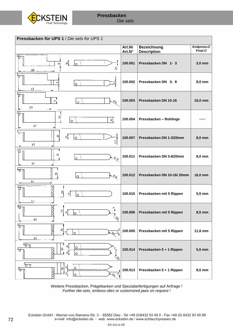
72
Pressbacken Die sets
sf
EN 412.02 DE
Weitere Pressbacken, Prägebacken und Spezialanfertigungen auf Anfrage !
Further die-sets, emboss-dies or customized jaws on request !
Pressbacken für UPS 1 / Die sets for UPS 1
Art.Nr Art.N°
Bezeichnung Description
Endpress-
Final
100.001
Pressbacken DN 1- 3
3,0 mm
100.002
Pressbacken DN 3- 8
8,0 mm
100.003
Pressbacken DN 10-16
16,0 mm
100.004
Pressbacken – Rohlinge
------
100.007
Pressbacken DN 1-3/20mm
8,0 mm
100.011
Pressbacken DN 3-8/20mm
8,0 mm
100.012
Pressbacken DN 10-16/ 20mm
16,0 mm
100.015
Pressbacken mit 5 Rippen
5,5 mm
100.006
Pressbacken mit 5 Rippen
8,5 mm
100.005
Pressbacken mit 5 Rippen
11,6 mm
100.014
Pressbacken 5 + 1 Rippen
5,5 mm
100.013
Pressbacken 5 + 1 Rippen
8,5 mm

Verkaufs- und Lieferungsbedingungen
1. Angebot, Unterlagen Wir liefern ausschließlich aufgrund dieser Verkaufs- und Lieferungsbedingungen. Geschäftsbedingungen des Bestellers gelten, auch wenn wir ihnen nicht ausdrücklich widersprochen haben, nur soweit sie mit unseren übereinstimmen. Vereinbarungen, mit denen von unseren Bedingungen abgewichen wird, gelten nur, wenn sie schriftlich getroffen werden. An Zeichnungen und anderen Unterlagen behalten wir uns das Eigentums- und Urheberrecht vor; sie dürfen ohne unsere Zustimmung weder verwertet noch Dritten zugänglich gemacht werden. Bereits im Angebotsstadium hat uns der Besteller schriftlich auf eine aus dem Rahmen fallende Beanspruchung an die zu liefernden Gegenstände, sowie andere Risiken hinzuweisen, die bei ihrer Verwendung entstehen können. Beziehen sich Angebote und Auftragsbestätigungen auf unseren Katalog oder unser Prospektmaterial, so gilt jeweils die letzte Ausgabe. Technische Änderungen bleiben vorbehalten. Angaben in Anzeigen beschreiben unsere Produkte, enthalten aber technisch nur Annäherungswerte.
2. Vertrag Der Umfang der beiderseitigen Verpflichtungen richtet sich nach unserer Auftragsbestätigung. Nebenabreden und Änderungen gelten nur, wenn wir sie schriftlich bestätigen.
3. Preise
Unsere Preise gelten ab Werk, ausschließlich Verpackung, die zum Selbstkostenpreis berechnet wird. Die Mehrwertsteuer ist im Preis nicht enthalten und wird gesondert in Rechnung gestellt. Verändern sich die für die Preisbildung maßgebenden Faktoren wie Löhne und/oder die Kosten für Material und/oder Betriebsstoffe, sind wir berechtigt, die Preise entsprechend anzupassen.
4. Zahlung Unsere Rechnungen sind zahlbar innerhalb von acht Tagen nach Rechnungsdatum mit 2 % Skonto vom Nettowarenwert oder innerhalb von 30 Tagen nach Rechnungsdatum netto. Eine Aufrechnung mit nicht anerkannten Gegenforderungen des Bestellers ist ausgeschlossen.
5. Lieferfrist Vereinbarte Lieferfristen beginnen mit dem Datum der Auftragsbestätigung. Sie sind eingehalten, wenn die Liefergegenstände bis Ablauf der Frist versandbereit sind. Die Lieferfristen verlängern sich angemessen bei Eintritt unvorhergesehener Hindernisse, die außerhalb unseres Willens liegen, wie Streik und Aussperrung, Betriebsstörungen, Verzögerung in der Anlieferung wesentlicher Materialien, gleichviel ob diese Hindernisse bei uns oder bei einem unserer Lieferanten eintreten. Derartige Umstände sind auch dann nicht von uns zu vertreten, wenn wir bereits im Verzuge sind. Treten sie ein, sind beide Parteien berechtigt, vom Vertrag zurückzutreten. Wir sind zu Teillieferungen berechtigt. Kommen wir mit der Lieferung in Verzug, kann der Besteller, nachdem eine von Ihm gesetzte angemessene Nachfrist verstrichen ist, vom Vertrag insoweit zurücktreten, wie wir bis zum Eingang der Rücktrittserklärung bei uns den Kaufgegenstand oder Teile davon noch nicht versandt haben. Andere Ansprüche wegen des Verzuges, insbesondere auf Schadenersatz, sind ausgeschlossen. Soweit dieser Ausschluß nicht zulässig ist, beschränkt sich unsere Haftung auf kausal auf unseren Verzug zurückzuführenden unmittelbaren Schäden.
6. Gefahrenübergang, Mehr- oder Minderlieferungen Unabhängig von der Art des Transportes und dessen Kosten reist die Ware auf Gefahr des Bestellers. Bei Sonderlieferungen werden angemessene Mehr- oder Minderlieferungen in der Lieferung berücksichtigt.
7. Eigentumsvorbehalt Die von uns gelieferten Gegenstände bleiben unser Eigentum bis alle unsere Ansprüche gegen den Besteller, gleich aus welchem Rechtsgrund, erfüllt sind.
8. Beanstandungen
Die von uns gelieferten Gegenstände gelten als genehmigt, wenn uns Beanstandungen nicht unverzüglich, das heißt, innerhalb einer Frist von 14 Tagen nach Absendung zugehen.
9. Gewährleistung Bei berechtigten Mängelrügen erfolgt nach unserer Wahl Nachbesserung, Ersatzlieferung oder Gutschrift. Schlägt die Nachbesserung fehl, ist der Besteller berechtigt, Wandlung des Kaufvertrages oder Minderung des Kaufpreises zu verlangen. Ansprüche auf Schadenersatz sind ausgeschlossen. Das gilt auch für Ansprüche auf Ersatz von Schäden, die nicht am Liefergegenstand selbst entstanden sind und für Schadenersatzansprüche wegen einer etwaigen schuldhaften Verletzung unserer Nachbesserungspflicht.
10. Haftung für Nebenpflichten Rat und Auskunft über die Verwendung unserer Liefergegenstände geben wir nach bestem Wissen, schließen jedoch unsere Haftung hierfür aus, weil die Verantwortung hinsichtlich Eignung und bestimmungsgemäßer Verwendung unserer Liefergegenstände beim Besteller liegt.
11. Produkthaftung
Für Fehler an unseren Liefergegenständen haften wir dem Besteller gegenüber ausschließlich gemäß der Bestimmungen in Abschnitt 8. Ansprüche des Bestellers aus Produkthaftung sind ausgeschlossen. Bitte beachten Sie, daß alle Angaben in diesem Katalog unseren Erfahrungswerten entsprechen und ausschließlich Ihrer Information dienen. Eine Verbindlichkeit kann daraus nicht hergeleitet werden.
12. Rücktrittsrecht Wird uns die Lieferung nachträglich unmöglich, ist der Besteller zum Rücktritt vom Vertrag berechtigt. Bei teilweiser Unmöglichkeit ist er zum Rücktritt hinsichtlich des Teiles der vertraglichen Leistung berechtigt, dessen Erfüllung unmöglich geworden ist. Schadenersatzansprüche wegen Rücktritts bestehen nicht.
13. Erfüllungsort, Gerichtsstand, anwendbares Recht Erfüllungsort für die Lieferung und Zahlung ist unser Geschäftssitz. Gerichtstand für beide Vertragspartner ist Diez/Lahn oder, nach unserer Wahl, der Geschäftssitz des Bestellers. Für alle Vereinbarungen und Rechtshandlungen der Vertragspartner gilt ergänzend zu den Vertragsbestimmungen nur das Recht der Bundesrepublik Deutschland.