
Notes - Willkommen - Reckmann Yacht Equipment
70
www.reckmann.com Instructions for use MF-x DF R 10-40 Manual reefing system Aluminium foils Wire / Rod Reckmann Yacht Equipment GmbH Siemensstr. 37-39 25462 Rellingen Germany Tel. +49(0) 4101 3849-0 Fax. +49(0) 4101 3849-50 [email protected] www.reckmann.com Revised: 2017-06-14 © Reckmann Yacht Equipment GmbH Siemensstr. 37-39 25462 Rellingen Germany
Transcript of Notes - Willkommen - Reckmann Yacht Equipment
ww
w.reckm
ann.com
Instructions for use
MF-x D
F R 10-40
Manual reefing system
Alum
inium foils
Wire / R
od
Pos: 2 /ZINDEL/_Steuermodule/Texte Tem
plate @ 1\m
od_1467358922020_26.docx @ 17211 @
@ 1
Revised
Table of contents Index
Germ
any Notes
Dim
ensions C
alculating the furling section length and the offcut measurem
ent === Ende der Liste für Textm
arke ref_template ===
Reckm
ann Yacht Equipment G
mbH
Siem
ensstr. 37-39 25462 R
ellingen G
ermany
Tel. +49(0) 4101 3849-0 Fax. +49(0) 4101 3849-50
info@reckm
ann.com
ww
w.reckm
ann.com
Revised: 2017-06-14
Pos: 4 /ZINDEL/Dokument/Copyright Reckm
ann @ 1\m
od_1467358562409_26.docx @ 17207 @
@ 1
© R
eckmann Y
acht Equipm
ent Gm
bH
Siem
ensstr. 37-39 25462 R
ellingen G
ermany
=== Ende der Liste für Textmarke Copyright ===
Dim
ensions
Pos: 6 /ZINDEL/Rollreffanlagen/Ausklappseite/AKS Maße M
F-x DF @ 1\m
od_1480952239305_26.docx @ 17926 @
@ 1
Pos: 1 /ZINDEL/Rollreffanlagen/Ausklappseite/AKS Berechnung der Profillänge RF90 DS @ 1\m
od_1426063204544_6.docx @ 12919 @
22 @ 1
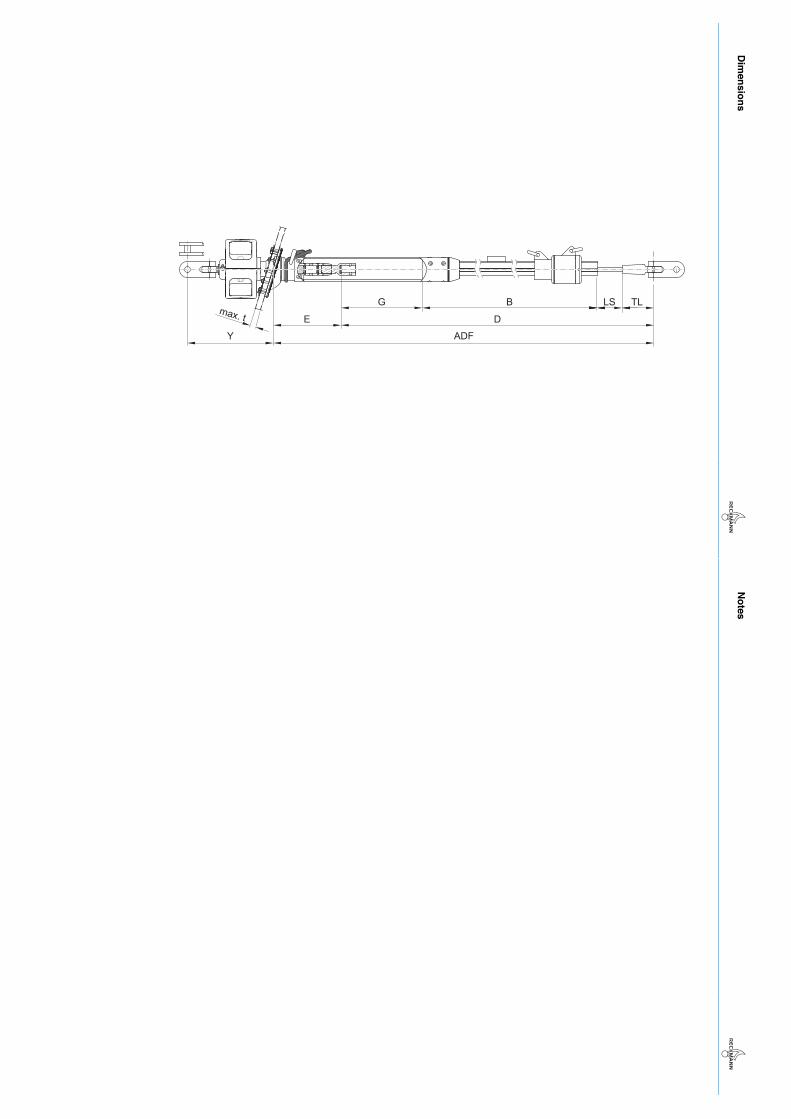
TLLSBD
ADF
GE
Y
max. t
=== Ende der Liste für Textmarke Inhalt1 ===
Notes
N
otes
C
alculating the furling section length and the offcut measurem
ent
Pos: 8 /ZINDEL/Rollreffanlagen/Ausklappseite/AKS Berechnung der Profillänge MF-x DF @
1\mod_1480410530079_26.docx @
17810 @ @
1
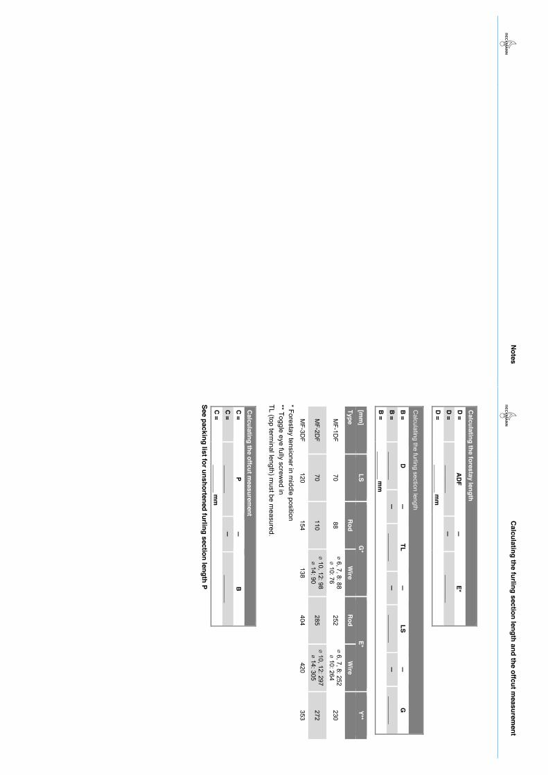
Calculating the forestay length
D =
AD
F —
E*
D =
________ —
________
D =
________ m
m
Calculating the furling section length
B =
D —
TL
—
LS —
G
B
= ________
—
________ —
________
—
________ B
=
________ mm
[mm
] LS
G*
E* Y**
Type
Rod
Wire
Rod
Wire
MF-1D
F 70
88 ⌀ 6, 7, 8: 88 ⌀ 10: 76
252 ⌀ 6, 7, 8: 252 ⌀ 10: 264
230
MF-2D
F 70
110 ⌀ 10, 12: 98 ⌀ 14: 90
285 ⌀ 10, 12: 297 ⌀ 14: 305
272
MF-3D
F 120
154 138
404 420
353
* Forestay tensioner in middle position
** Toggle eye fully screwed in
TL (top terminal length) m
ust be measured.
Calculating the offcut m
easurement
C =
P —
B
C =
________ —
________
C =
________ m
m
See packing list for unshortened furling section length P === Ende der Liste für Textm
arke Inhalt ===
=== Ende der Liste für Textmarke Inhalt2 ===
N
otes
ww
w.reckm
ann.com

Table of contents
MF-x DF R10-40 2017-06-09 1
1 Packing list ........................................................................................................... 4
2 About this manual ................................................................................................ 7
2.1 Introduction ........................................................................................................................ 7
2.2 Furling systems to which this manual applies .................................................................... 7
2.3 Display conventions ........................................................................................................... 8
2.4 Calculations ....................................................................................................................... 8
3 Safety .................................................................................................................... 9
3.1 Intended use ...................................................................................................................... 9
3.2 Information for the safe use ............................................................................................. 10
3.3 Hazards from improper use of the furling system ............................................................. 10
3.4 Installation and maintenance safety instructions .............................................................. 10
4 Design and function ........................................................................................... 11
4.1 Overview .......................................................................................................................... 11
4.2 Forestay tensioner ........................................................................................................... 12
4.3 Function ........................................................................................................................... 12
5 Assembly ............................................................................................................ 13
5.1 Preparing the forestay ...................................................................................................... 13 5.1.1 Adjusting the furling section length ....................................................................................... 13 5.1.2 Preparing the top bushing .................................................................................................... 14 5.1.3 Preparing the rod forestay .................................................................................................... 15 5.1.4 Preparing the wire forestay .................................................................................................. 19
5.2 Installing the deck flange .................................................................................................. 23 5.2.1 Overview of the installation steps ......................................................................................... 23 5.2.2 Making a hole in the deck..................................................................................................... 24 5.2.3 Provisional setting of the length of the drum bearing unit .................................................... 25 5.2.4 Provisional connection of the forestay to the drum bearing unit ........................................... 27 5.2.5 Provisional hoisting of the system ........................................................................................ 30 5.2.6 Provisional setting of the forestay length .............................................................................. 31 5.2.7 Checking the gap dimension in the deck hole and adjusting if necessary ........................... 33 5.2.8 Laying on the deck flange and underpinning if necessary ................................................... 34 5.2.9 Screwing on the deck flange ................................................................................................ 36
5.3 Detaching the forestay from the forestay adapter ............................................................ 37
5.4 Fitting the furling sections ................................................................................................ 38
5.5 Fitting the bushing stopper (with rod forestay, no furling section reinforcement) ............. 39
5.6 Fitting the furling section reinforcement (optional, only for rod forestay) .......................... 40
Table of contents
2 2017-06-09 MF-x DF R10-40
5.7 Fitting the sail feeder and the halyard swivel ................................................................... 41
5.8 Sliding the furling section adapter onto the furling section ............................................... 41
5.9 Finally connecting the forestay to the furling system ....................................................... 42 5.9.1 Finally connecting the rod forestay to the furling system ...................................................... 42 5.9.2 Finally connecting the wire forestay to the furling system .................................................... 43
5.10 Fitting the furling section adapter to the furling section .................................................... 44
5.11 Mounting the top bushing ................................................................................................ 44
5.12 Finally hoisting the system .............................................................................................. 45 5.12.1 Toggle on the masthead ....................................................................................................... 45 5.12.2 Fixing the system to the toggle ............................................................................................. 45
5.13 Adjusting the forestay length ........................................................................................... 46
5.14 Fixing the furling section adapter to the tack ring ............................................................ 49
5.15 Moving the halyard swivel into final position .................................................................... 50
5.16 Fitting the furling rope to the drum ................................................................................... 50
5.17 Installing the drum ........................................................................................................... 51
5.18 Fitting the protective cage ............................................................................................... 53
5.19 Direction of rotation ......................................................................................................... 54
5.20 Guiding the furling rope ................................................................................................... 54
6 Operation ............................................................................................................ 55
6.1 Wire pennant ................................................................................................................... 55
6.2 Furling and unfurling the sail ........................................................................................... 56 6.2.1 Furling ................................................................................................................................... 56 6.2.2 Unfurling the sail ................................................................................................................... 56 6.2.3 Reefing ................................................................................................................................. 57
6.3 Use as a forestay furling section ...................................................................................... 58
7 Maintenance ....................................................................................................... 59
7.1 Prior to each use ............................................................................................................. 59
7.2 After each use ................................................................................................................. 59
7.3 Annual maintenance ........................................................................................................ 59
8 Disassembly ....................................................................................................... 60
9 Storage ................................................................................................................ 62
10 Disposal .............................................................................................................. 63
11 Technical data .................................................................................................... 64
Table of contents
MF-x DF R10-40 2017-06-09 3
11.1 Dimensions ...................................................................................................................... 64
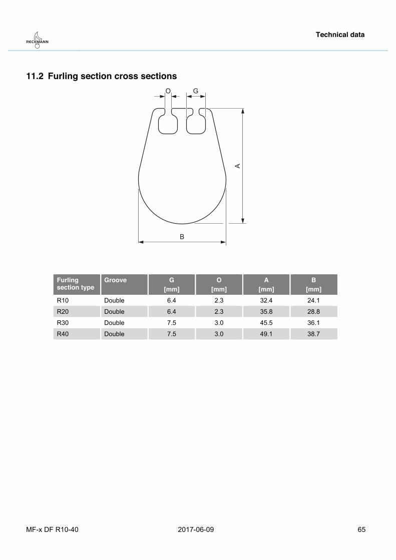
11.2 Furling section cross sections .......................................................................................... 65
12 Index .................................................................................................................... 66
Pos: 4 /ZINDEL/Rollreffanlagen/Identifikation/Packliste MF-x DF-alt @ 1\mod_1478526954869_26.docx @ 17646 @ 1 @ 1
Packing list
4 2017-06-09 MF-x DF R10-40
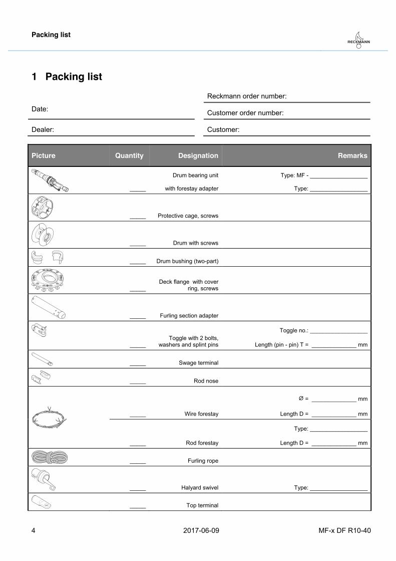
1 Packing list
Reckmann order number:
Date: Customer order number:
Dealer: Customer:
Picture Quantity Designation Remarks
_____
Drum bearing unit
with forestay adapter
Type: MF - __________________
Type: __________________
_____ Protective cage, screws
_____ Drum with screws
_____ Drum bushing (two-part)
_____ Deck flange with cover
ring, screws
_____ Furling section adapter
_____
Toggle with 2 bolts, washers and splint pins
Toggle no.: __________________
Length (pin - pin) T = ______________ mm
_____ Swage terminal
_____ Rod nose
_____ Wire forestay
⌀ = ______________ mm
Length D = ______________ mm
_____ Rod forestay
Type: __________________
Length D = ______________ mm
_____ Furling rope
_____ Halyard swivel Type: __________________
_____ Top terminal
Packing list
MF-x DF R10-40 2017-06-09 5
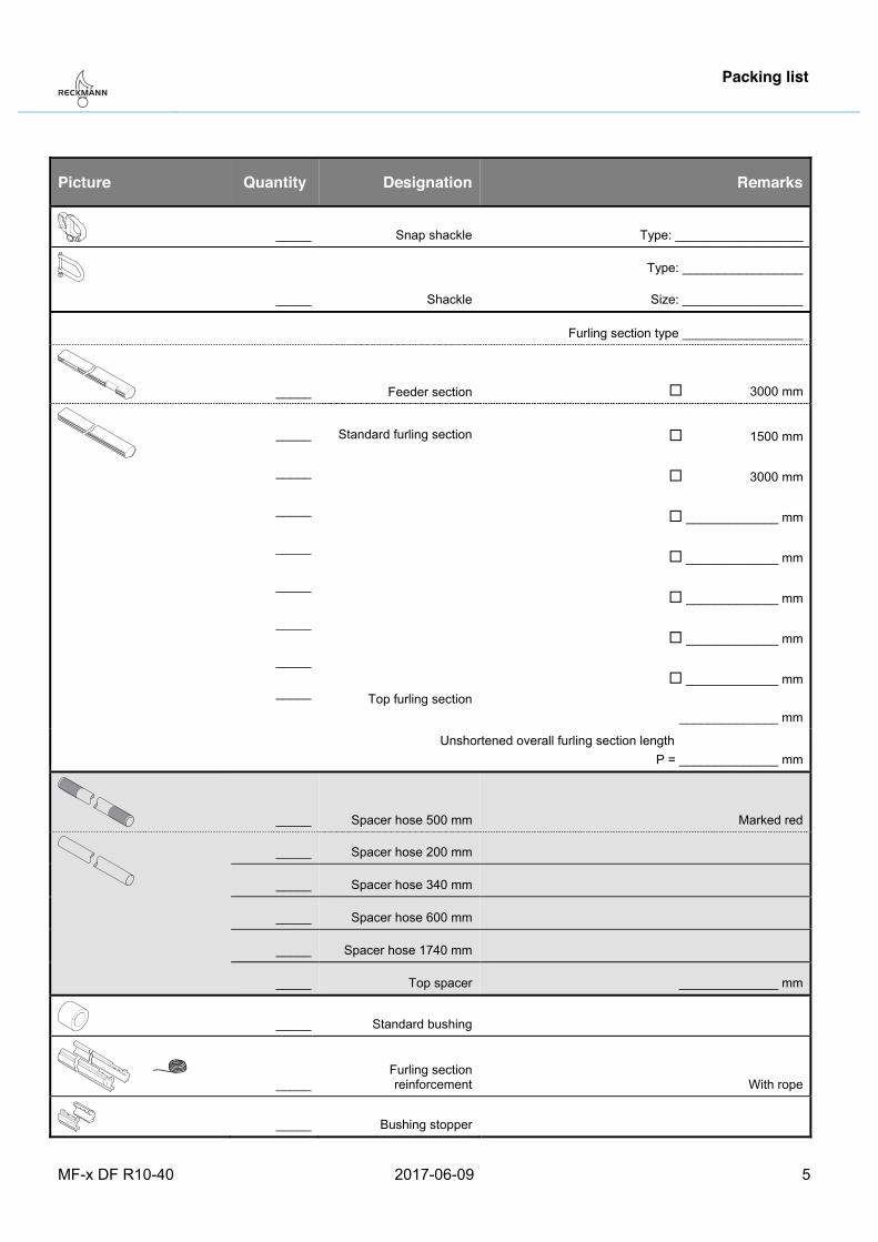
Picture Quantity Designation Remarks
_____ Snap shackle Type: __________________
_____ Shackle
Type: _________________
Size: _________________
Furling section type _________________
_____ Feeder section � 3000 mm
_____
_____
_____
_____
_____
_____
_____
_____
Standard furling section
Top furling section
� 1500 mm
� 3000 mm
� _____________ mm
� _____________ mm
� _____________ mm
� _____________ mm
� _____________ mm
______________ mm
Unshortened overall furling section length P = ______________ mm
_____ Spacer hose 500 mm Marked red
_____ Spacer hose 200 mm
_____ Spacer hose 340 mm
_____ Spacer hose 600 mm
_____ Spacer hose 1740 mm
_____ Top spacer ______________ mm
_____ Standard bushing
_____ Furling section reinforcement With rope
_____ Bushing stopper
Packing list
6 2017-06-09 MF-x DF R10-40
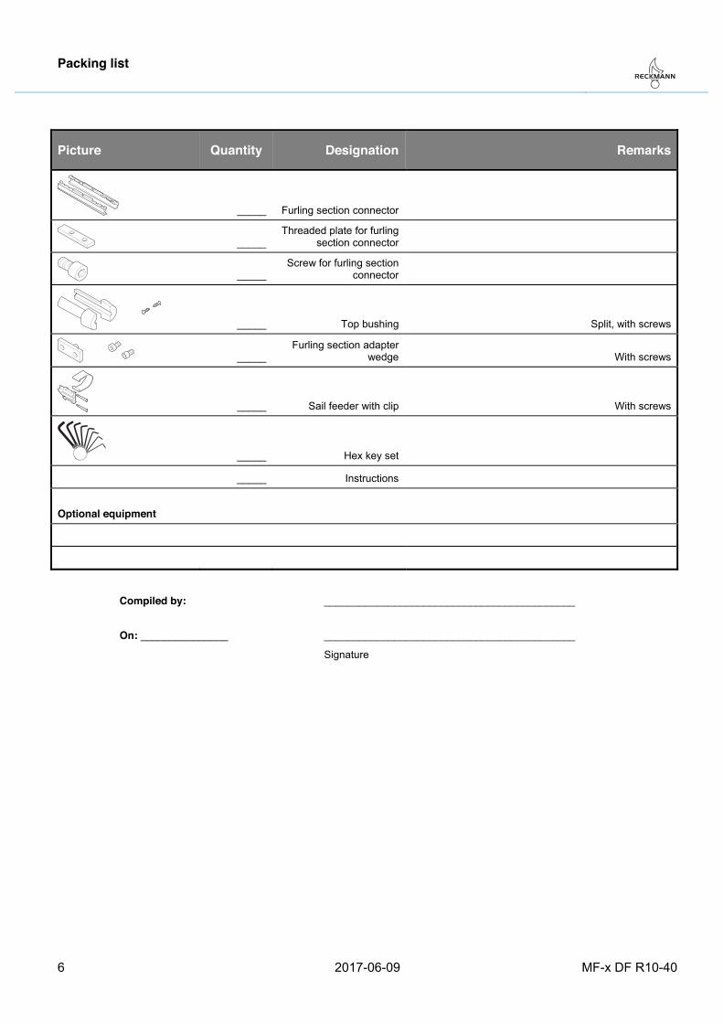
Picture Quantity Designation Remarks
_____ Furling section connector
_____ Threaded plate for furling
section connector
_____ Screw for furling section
connector
_____ Top bushing Split, with screws
_____ Furling section adapter
wedge With screws
_____ Sail feeder with clip With screws
_____ Hex key set
_____ Instructions
Optional equipment
Compiled by:
___________________________________________
On: _______________ ___________________________________________
Signature
Pos: 5 /ZINDEL/Dokument/headline_Über diese Betriebsanleitung @ 1\mod_1400498832886_26.docx @ 9825 @ 1 @ 1
About this manual
MF-x DF R10-40 2017-06-09 7
2 About this manual Pos: 6 /ZINDEL/Dokument/Zielgruppe klein @ 1\mod_1400499035332_26.docx @ 9828 @ 2 @ 1
2.1 Introduction These instructions are directed at owners of furling systems as well as anyone involved in the assembly, use or maintenance of such systems.
Its use requires the appropriate sailing qualifications. Inexperienced individuals on board must be trained and supervised by the skipper.
Assembly and repair work may only be carried out by qualified specialists.
Read the instructions before using the furling system or carrying out any assembly, disassembly or maintenance work.
Pos: 7 /ZINDEL/Dokument/Identifikation Typen MF-x DF R10-40 @ 1\mod_1480428214449_26.docx @ 17851 @ 2 @ 1
2.2 Furling systems to which this manual applies These instructions provide information for the following furling systems with the specified profile types:
Manual furling systems (below deck version) MF-1 DF MF-2 DF MF-3 DF
Profile types (aluminium) R10 R20 R30 R40
Pos: 8 /ZINDEL/Dokument/Darstellungskonventionen @ 1\mod_1400502131053_26.docx @ 9834 @ 2 @ 1
About this manual
8 2017-06-09 MF-x DF R10-40
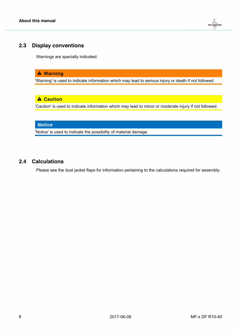
2.3 Display conventions
Warnings are specially indicated:
Warning 'Warning' is used to indicate information which may lead to serious injury or death if not followed.
Caution 'Caution' is used to indicate information which may lead to minor or moderate injury if not followed.
Notice 'Notice' is used to indicate the possibility of material damage.
Pos: 9 /ZINDEL/Dokument/Berechnungen finden @ 1\mod_1429777515530_26.docx @ 13180 @ 2 @ 1
2.4 Calculations Please see the dust jacket flaps for information pertaining to the calculations required for assembly.
Pos: 10 /ZINDEL/Rollreffanlagen/Sicherheit/headline_Sicherheit @ 1\mod_1400506586530_26.docx @ 9845 @ 1 @ 1
Safety
MF-x DF R10-40 2017-06-09 9
3 Safety Pos: 11 /ZINDEL/Rollreffanlagen/Sicherheit/Bestimmungsgemäße Verwendung MF-x DF @ 1\mod_1478527542909_26.docx @ 17661 @ 2 @ 1
3.1 Intended use
The furling system is designed for reefing or furling a fore sail by rolling it up. It is operated by a furling rope on a drum. The sail can be rolled up completely (furled) or partially (reefed).
The furling system is equipped with a length adjuster for the trimming of mast and sail. The length adjuster should be used at the mooring, not when sailing.
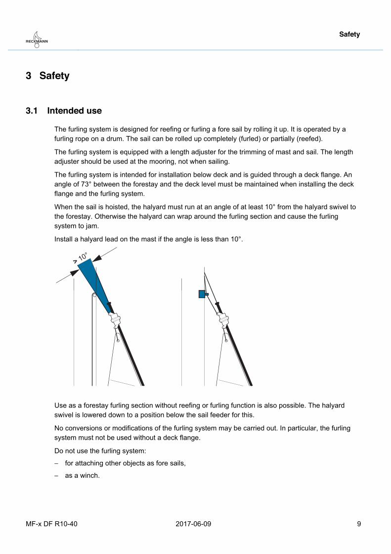
The furling system is intended for installation below deck and is guided through a deck flange. An angle of 73° between the forestay and the deck level must be maintained when installing the deck flange and the furling system.
When the sail is hoisted, the halyard must run at an angle of at least 10° from the halyard swivel to the forestay. Otherwise the halyard can wrap around the furling section and cause the furling system to jam.
Install a halyard lead on the mast if the angle is less than 10°.
Use as a forestay furling section without reefing or furling function is also possible. The halyard swivel is lowered down to a position below the sail feeder for this.
No conversions or modifications of the furling system may be carried out. In particular, the furling system must not be used without a deck flange.
Do not use the furling system:
− for attaching other objects as fore sails,
− as a winch. Pos: 12 /ZINDEL/Rollreffanlagen/Sicherheit/Sicherheitsinformationen @ 1\mod_1443790244103_26.docx @ 15931 @ 2 @ 1
> 10°

Safety
10 2017-06-09 MF-x DF R10-40
3.2 Information for the safe use • Read these instructions before using or working on the furling system.
• Always keep the instructions close to the furling system.
• In addition to these instructions for use, the owner's manual and manuals for other on-boardequipment must be observed.
Pos: 13 /ZINDEL/Rollreffanlagen/Sicherheit/Sicherheitshinweise Bedienung MF-x DF @ 1\mod_1480430087715_26.docx @ 17856 @ 2 @ 1
3.3 Hazards from improper use of the furling system Parts of the body, hair or clothing may get caught in the area of the deck flange and the sail attachment. Fingers may be crushed. The furling system may move in the wind.
The furling system and the furling rope pose a risk of stumbling.
Observe the following instructions:
• Its use requires the appropriate sailing qualifications. Inexperienced individuals on board mustbe trained and supervised by a trained individual. Do not leave children unattended on thefurling system.
• Prior to each use, check the furling system for damage. Do not use the furling system if it is damaged.
• When using the furling system, make sure that no one is in the direct vicinity of the system.
• Always exercise prudence on board.Pos: 14 /ZINDEL/Rollreffanlagen/Sicherheit/Sicherheitshinweise Montage und Instandhaltung @ 1\mod_1443797182650_26.docx @ 15936 @ 2 @ 1
3.4 Installation and maintenance safety instructions Improper installation and maintenance may result in serious injury including death.
• Assembly and repair work may only be carried out by qualified specialists at a location with suitable equipment. Use appropriate slings to lift the system.
• Carry out all maintenance tasks and inspection at the intervals specified in these instructions for use.
• Only carry out the repairs maintenance tasks described in these instructions. For any other repairs please consult a service station.
Pos: 15 /ZINDEL/Rollreffanlagen/Aufbau und Funktion/headline_Aufbau und Funktion @ 1\mod_1400762844571_26.docx @ 9966 @ 1 @ 1
Design and function
MF-x DF R10-40 2017-06-09 11
4 Design and function Pos: 16 /ZINDEL/Rollreffanlagen/Aufbau und Funktion/Übersicht MF-x DF @ 1\mod_1478268837188_26.docx @ 17641 @ 2 @ 1
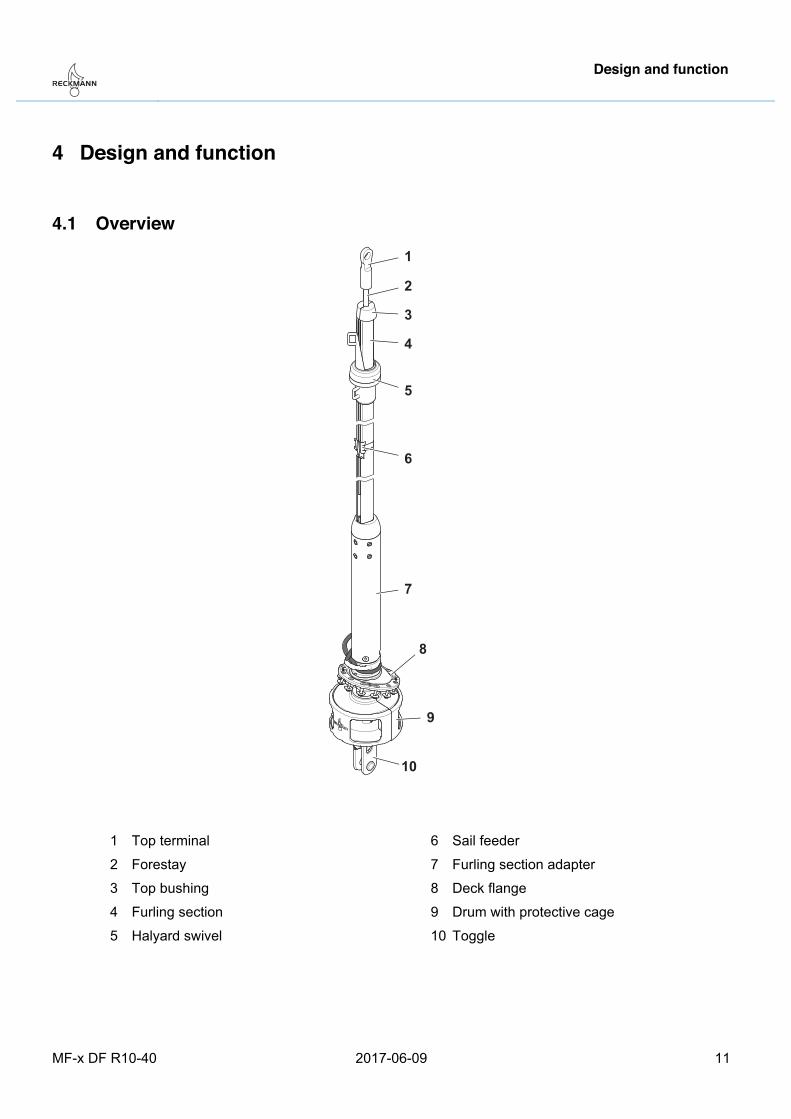
4.1 Overview
1
2
3
4
5
7
8
9
6
10
1 Top terminal
2 Forestay
3 Top bushing
4 Furling section
5 Halyard swivel
6 Sail feeder
7 Furling section adapter
8 Deck flange
9 Drum with protective cage
10 Toggle
Pos: 17 /ZINDEL/Rollreffanlagen/Aufbau und Funktion/Vorstagspanner MF-x DF @ 1\mod_1478527235566_26.docx @ 17651 @ 2 @ 1
Design and function
12 2017-06-09 MF-x DF R10-40
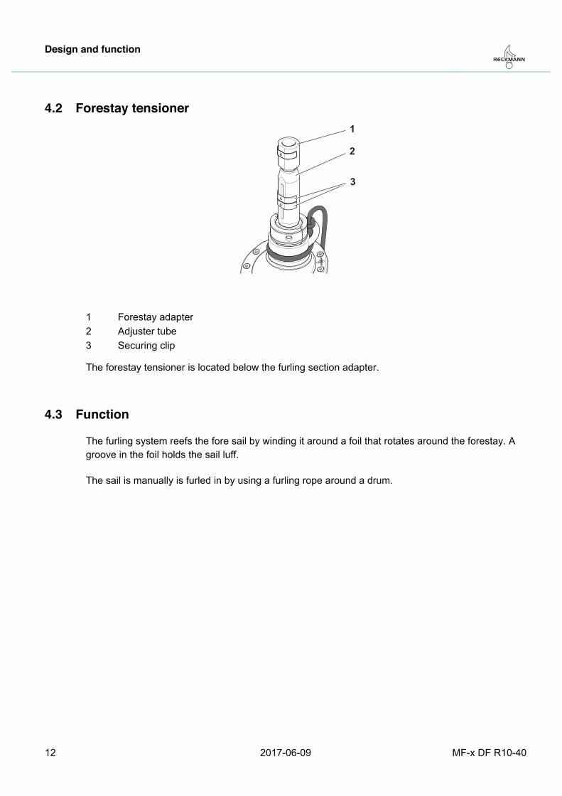
4.2 Forestay tensioner 1
2
3
1 Forestay adapter 2 Adjuster tube 3 Securing clip
The forestay tensioner is located below the furling section adapter. Pos: 18 /ZINDEL/Rollreffanlagen/Aufbau und Funktion/Funktion-Rollreff @ 1\mod_1400763386014_26.docx @ 9972 @ 2 @ 1
4.3 Function
The furling system reefs the fore sail by winding it around a foil that rotates around the forestay. A groove in the foil holds the sail luff.
Pos: 19 /ZINDEL/Rollreffanlagen/Aufbau und Funktion/Funktion-manuell @ 1\mod_1444053202953_26.docx @ 15956 @ @ 1
The sail is manually is furled in by using a furling rope around a drum. Pos: 20 /ZINDEL/Rollreffanlagen/Montage/headline_Montage @ 1\mod_1415351350590_26.docx @ 10560 @ 1 @ 1
Assembly
MF-x DF R10-40 2017-06-09 13
5 Assembly Pos: 21 /ZINDEL/Rollreffanlagen/Montage/Alu/R10 - R40/headline_Vorstag komplettieren @ 1\mod_1444382618588_26.docx @ 16026 @ 2 @ 1
5.1 Preparing the forestay Pos: 22 /ZINDEL/Rollreffanlagen/Montage/Alu/R10 - R40/Profillänge anpassen - Einführung @ 1\mod_1401706466725_26.docx @ 10176 @ 3 @ 1
5.1.1 Adjusting the furling section length
If a top furling section and a top spacer are not specified on the packing list at the beginning of these instructions for use, a furling section and a corresponding spacer hose must be shortened by the offcut measurement 'C'.
For the offcut measurement 'C', please see the calculations on the flap. Pos: 23 /ZINDEL/Rollreffanlagen/Montage/Alu/R10 - R40/Profil kürzen (R10 - R40) @ 1\mod_1400586602689_26.docx @ 9886 @ 4 @ 1
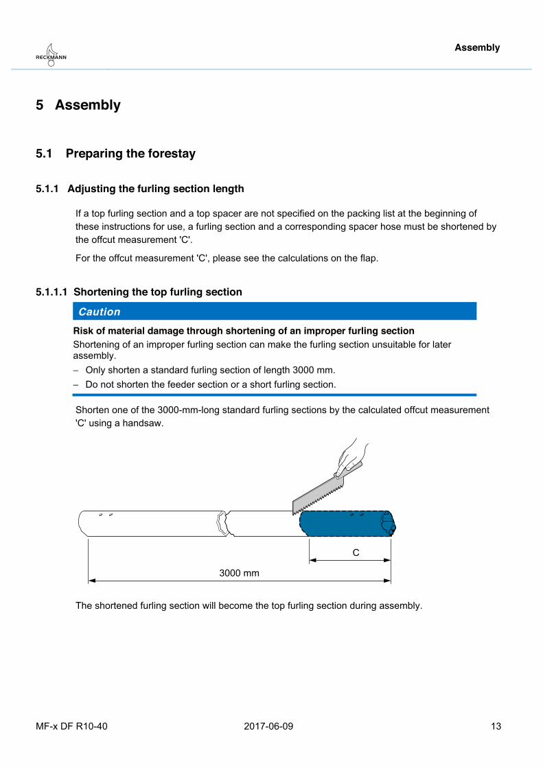
5.1.1.1 Shortening the top furling section
Caution Risk of material damage through shortening of an improper furling section Shortening of an improper furling section can make the furling section unsuitable for later assembly. − Only shorten a standard furling section of length 3000 mm. − Do not shorten the feeder section or a short furling section.
Shorten one of the 3000-mm-long standard furling sections by the calculated offcut measurement 'C' using a handsaw.
The shortened furling section will become the top furling section during assembly. Pos: 24 /ZINDEL/Rollreffanlagen/Montage/Alu/R10 - R40/Schlauch kürzen (R10 - R40) @ 1\mod_1399625751186_26.docx @ 9638 @ 4 @ 1

Assembly
14 2017-06-09 MF-x DF R10-40
5.1.1.2 Shortening the top spacer
Shorten the 1740-mm-long spacer hose by the amount 'C' using a sharp knife.
The shortened spacer hose will become the top spacer during assembly. Pos: 25 /ZINDEL/Rollreffanlagen/Montage/Alu/R10 - R40/Topkappe vorbereiten (R10 - R40) @ 1\mod_1399557777207_26.docx @ 9621 @ 3 @ 1
5.1.2 Preparing the top bushing
After assembly the top bushing will cover the top furling section.
The following can be used as a top furling section:
− a standard furling section that has been shortened to a length less than 3000 mm but greater than 1500 mm,
− if furling section shortening is not necessary, a standard furling section of length 3000 mm.
1. Insert the two halves of the top bushing into the top furling section in such a way that the join line formed by their mating surfaces is lined up with the groove in the furling section.
Assembly
MF-x DF R10-40 2017-06-09 15
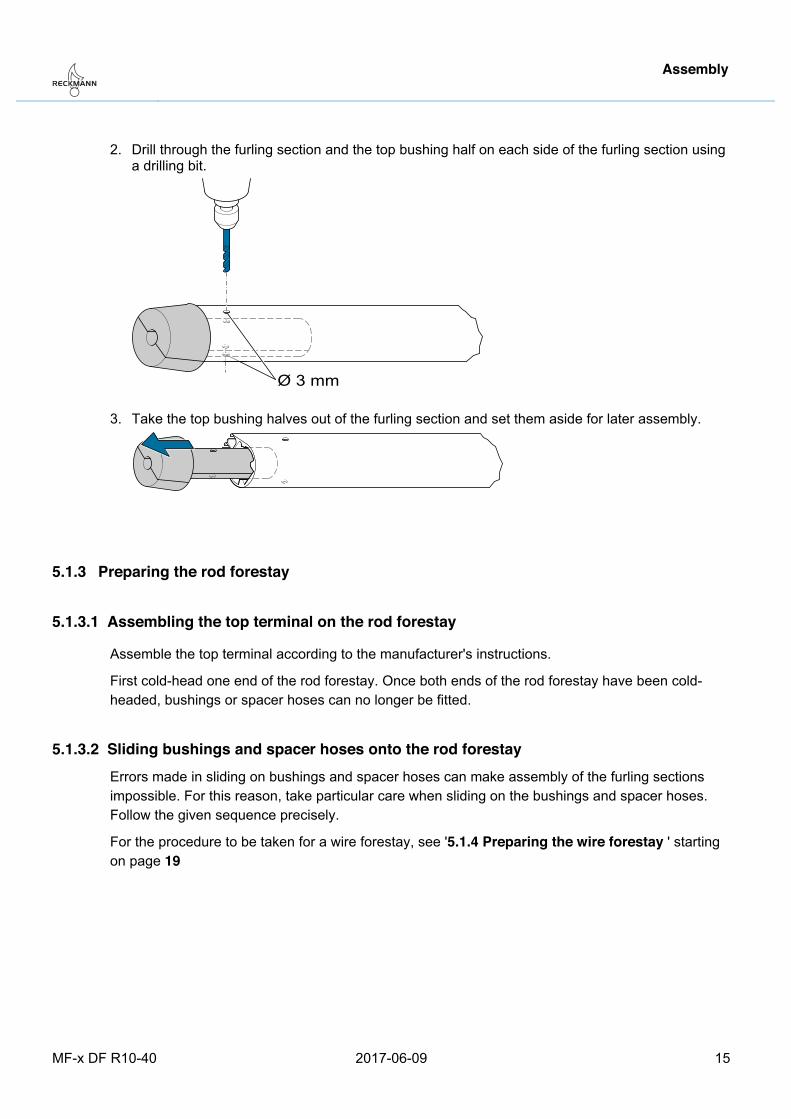
2. Drill through the furling section and the top bushing half on each side of the furling section using a drilling bit.
3. Take the top bushing halves out of the furling section and set them aside for later assembly.
Pos: 26 /ZINDEL/Rollreffanlagen/Montage/Alu/R10 - R40/rod/headline_Rodvorstag vorbereiten @ 1\mod_1425888645936_26.docx @ 12670 @ 3 @ 1
5.1.3 Preparing the rod forestay Pos: 27 /ZINDEL/Rollreffanlagen/Montage/Alu/R10 - R40/rod/Terminal auf Rod montieren R10-R40 @ 1\mod_1411647417297_26.docx @ 10403 @ 4 @ 1
5.1.3.1 Assembling the top terminal on the rod forestay
Assemble the top terminal according to the manufacturer's instructions.
First cold-head one end of the rod forestay. Once both ends of the rod forestay have been cold-headed, bushings or spacer hoses can no longer be fitted.
Pos: 28 /ZINDEL/Rollreffanlagen/Montage/Alu/R10 - R40/rod/Buchsen und Schläuche auf Rod aufschieben MF @ 1\mod_1454599983040_26.docx @ 16576 @ 455555 @ 1
5.1.3.2 Sliding bushings and spacer hoses onto the rod forestay Errors made in sliding on bushings and spacer hoses can make assembly of the furling sections impossible. For this reason, take particular care when sliding on the bushings and spacer hoses. Follow the given sequence precisely.
For the procedure to be taken for a wire forestay, see '5.1.4 Preparing the wire forestay ' starting on page 19
Assembly
16 2017-06-09 MF-x DF R10-40
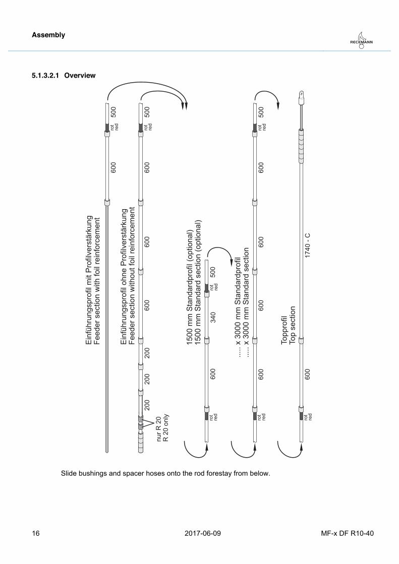
5.1.3.2.1 Overview
rot
red
rot
red
rot
red
rot
red
rot
red
rot
red
600
600
600
500
340
600
600
500
600
600
600
1740
- C
500
600
200
200
200
.....
x 30
00 m
m S
tand
ardp
rofil
.....
x 30
00 m
m S
tand
ard
sect
ion
1500
mm
Sta
ndar
dpro
fil (o
ptio
nal)
1500
mm
Sta
ndar
d se
ctio
n (o
ptio
nal)
Topp
rofil
Top
sect
ion
Einf
ühru
ngsp
rofil
ohn
e Pr
ofilv
erst
ärku
ngFe
eder
sec
tion
with
out f
oil r
einf
orce
men
t
nur R
20
R 2
0 on
ly
rot
red
600
500
Einf
ühru
ngsp
rofil
mit
Prof
ilver
stär
kung
Feed
er s
ectio
n w
ith fo
il re
info
rcem
ent
Slide bushings and spacer hoses onto the rod forestay from below.
Assembly
MF-x DF R10-40 2017-06-09 17
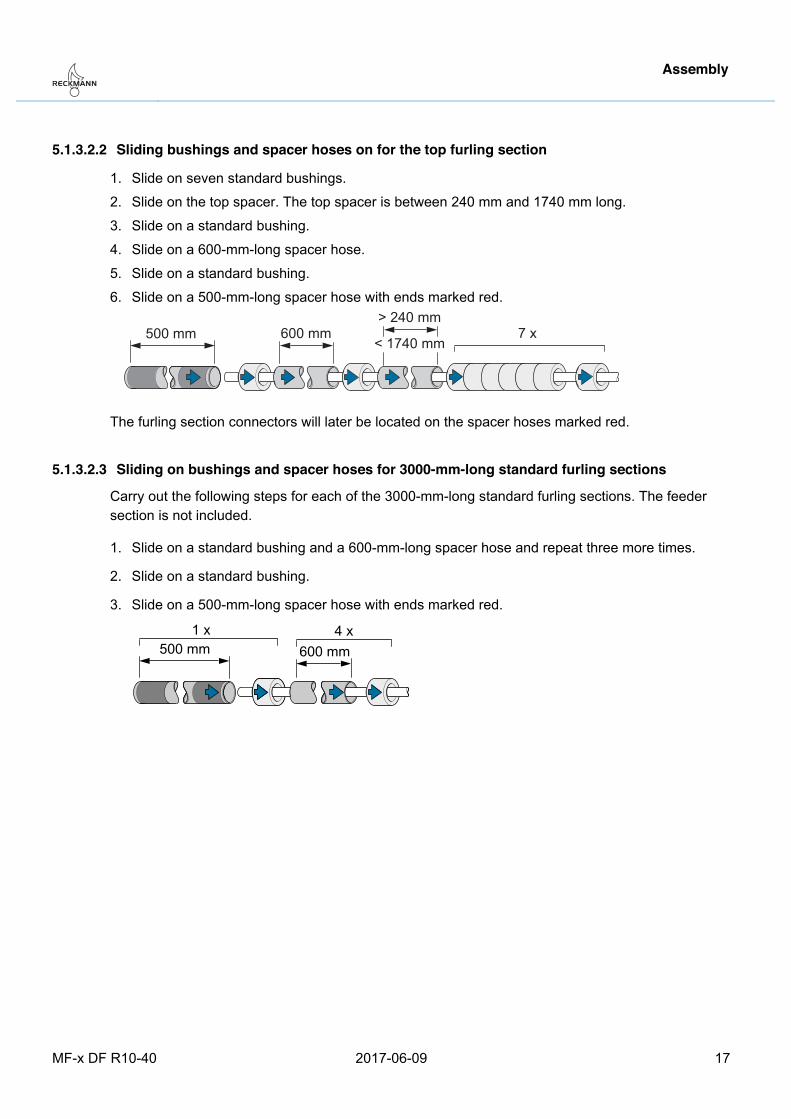
5.1.3.2.2 Sliding bushings and spacer hoses on for the top furling section
1. Slide on seven standard bushings.
2. Slide on the top spacer. The top spacer is between 240 mm and 1740 mm long.
3. Slide on a standard bushing.
4. Slide on a 600-mm-long spacer hose.
5. Slide on a standard bushing.
6. Slide on a 500-mm-long spacer hose with ends marked red.
600 mm> 240 mm
< 1740 mm500 mm 7 x
The furling section connectors will later be located on the spacer hoses marked red.
5.1.3.2.3 Sliding on bushings and spacer hoses for 3000-mm-long standard furling sections
Carry out the following steps for each of the 3000-mm-long standard furling sections. The feeder section is not included.
1. Slide on a standard bushing and a 600-mm-long spacer hose and repeat three more times.
2. Slide on a standard bushing.
3. Slide on a 500-mm-long spacer hose with ends marked red.
Assembly
18 2017-06-09 MF-x DF R10-40
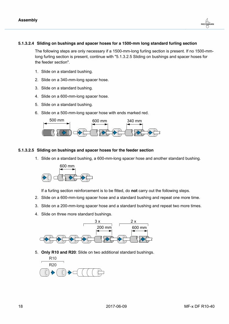
5.1.3.2.4 Sliding on bushings and spacer hoses for a 1500-mm long standard furling section
The following steps are only necessary if a 1500-mm-long furling section is present. If no 1500-mm-long furling section is present, continue with "5.1.3.2.5 Sliding on bushings and spacer hoses for the feeder section".
1. Slide on a standard bushing.
2. Slide on a 340-mm-long spacer hose.
3. Slide on a standard bushing.
4. Slide on a 600-mm-long spacer hose.
5. Slide on a standard bushing.
6. Slide on a 500-mm-long spacer hose with ends marked red.
5.1.3.2.5 Sliding on bushings and spacer hoses for the feeder section
1. Slide on a standard bushing, a 600-mm-long spacer hose and another standard bushing.
If a furling section reinforcement is to be fitted, do not carry out the following steps.
2. Slide on a 600-mm-long spacer hose and a standard bushing and repeat one more time.
3. Slide on a 200-mm-long spacer hose and a standard bushing and repeat two more times.
4. Slide on three more standard bushings.
5. Only R10 and R20: Slide on two additional standard bushings.
R10R20
Pos: 29 /ZINDEL/Rollreffanlagen/Montage/Alu/R10 - R40/rod/Rodkopf pressen_MF @ 1\mod_1444383649755_26.docx @ 16031 @ 4 @ 1
Assembly
MF-x DF R10-40 2017-06-09 19
5.1.3.3 Cold-heading the rod head
Caution After the rod head has been cold-headed no more bushings or spacer hoses can be fitted and their order can no longer be changed. Only cold-head the lower rod head after ensuring that all bushings and spacer hoses have been properly installed.
Cold-head the rod head according to the rod manufacturer's instructions.
Once the rod head has been cold-headed, continue the assembly with 5.2 Installing the deck flange.
Pos: 30 /ZINDEL/Rollreffanlagen/Montage/Alu/R10 - R40/wire/headline_Drahtvorstag vorbereiten @ 1\mod_1425888923859_26.docx @ 12673 @ 3 @ 1
5.1.4 Preparing the wire forestay Pos: 31 /ZINDEL/Rollreffanlagen/Montage/wire/Walzterminal @ 1\mod_1425396390203_26.docx @ 12640 @ 4 @ 1
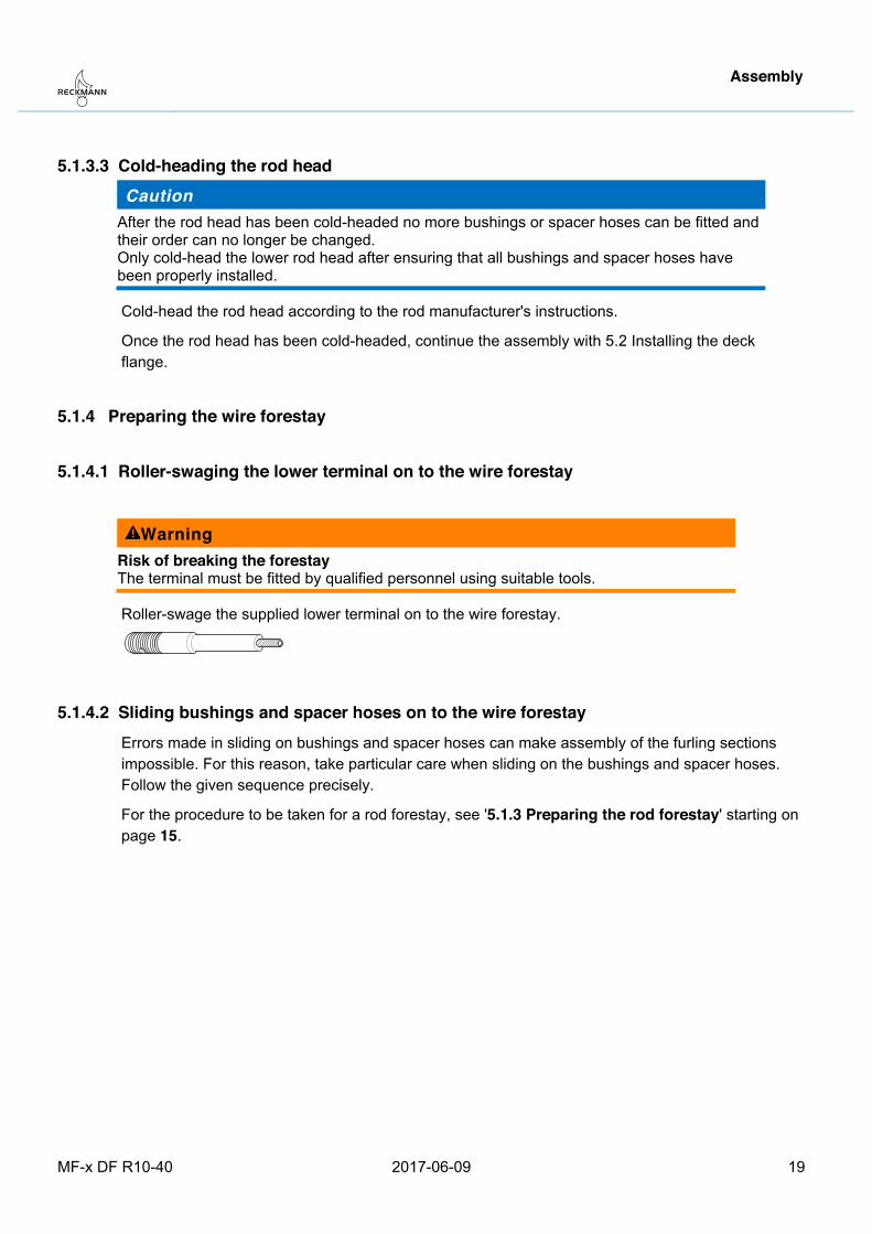
5.1.4.1 Roller-swaging the lower terminal on to the wire forestay
Warning Risk of breaking the forestay The terminal must be fitted by qualified personnel using suitable tools.
Roller-swage the supplied lower terminal on to the wire forestay.
Pos: 32 /ZINDEL/Rollreffanlagen/Montage/Alu/R10 - R40/wire/Buchsen und Schläuche auf Draht aufschieben MF @ 1\mod_1454600434444_26.docx @ 16581 @ 455555 @ 1
5.1.4.2 Sliding bushings and spacer hoses on to the wire forestay Errors made in sliding on bushings and spacer hoses can make assembly of the furling sections impossible. For this reason, take particular care when sliding on the bushings and spacer hoses. Follow the given sequence precisely.
For the procedure to be taken for a rod forestay, see '5.1.3 Preparing the rod forestay' starting on page 15.
Assembly
20 2017-06-09 MF-x DF R10-40
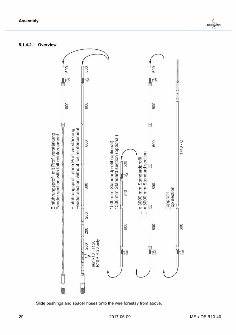
5.1.4.2.1 Overview
rot
red
rot
red
rot
red
rot
red
rot
red
rot
red
600
600
Einf
ühru
ngsp
rofil
ohn
e Pr
ofilv
erst
ärku
ngFe
eder
sec
tion
with
out f
oil r
einf
orce
men
t
600
500
340
600
600
500
600
600
.....
x 30
00 m
m S
tand
ardp
rofil
.....
x 30
00 m
m S
tand
ard
sect
ion
1500
mm
Sta
ndar
dpro
fil (o
ptio
nal)
1500
mm
Sta
ndar
d se
ctio
n (o
ptio
nal)
600
1740
- C
Topp
rofil
Top
sect
ion
500
600
200
nur R
10 +
R 2
0R
10 +
R 2
0 on
ly
200
200
rot
red
600
Einf
ühru
ngsp
rofil
mit
Prof
ilver
stär
kung
Feed
er s
ectio
n w
ith fo
il re
info
rcem
ent
500
Slide bushings and spacer hoses onto the wire forestay from above.
Assembly
MF-x DF R10-40 2017-06-09 21
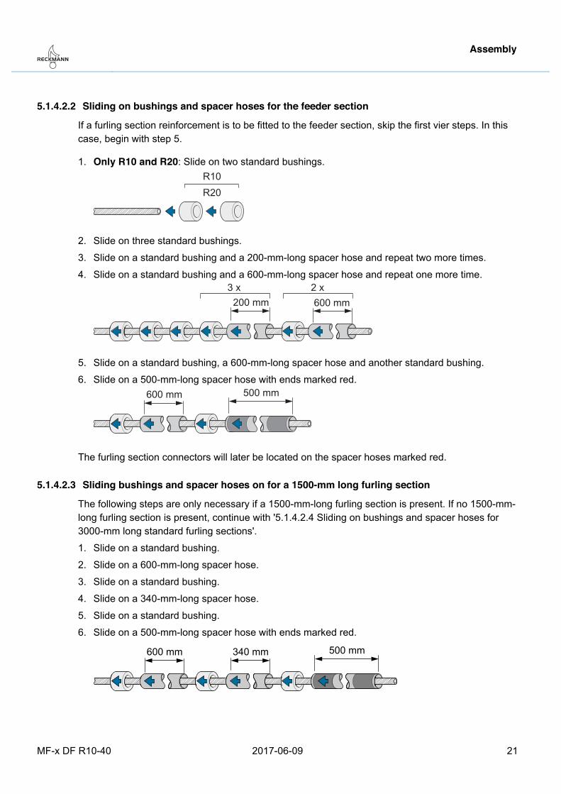
5.1.4.2.2 Sliding on bushings and spacer hoses for the feeder section
If a furling section reinforcement is to be fitted to the feeder section, skip the first vier steps. In this case, begin with step 5.
1. Only R10 and R20: Slide on two standard bushings.
R10R20
2. Slide on three standard bushings.
3. Slide on a standard bushing and a 200-mm-long spacer hose and repeat two more times.
4. Slide on a standard bushing and a 600-mm-long spacer hose and repeat one more time.
5. Slide on a standard bushing, a 600-mm-long spacer hose and another standard bushing.
6. Slide on a 500-mm-long spacer hose with ends marked red.
The furling section connectors will later be located on the spacer hoses marked red.
5.1.4.2.3 Sliding bushings and spacer hoses on for a 1500-mm long furling section
The following steps are only necessary if a 1500-mm-long furling section is present. If no 1500-mm-long furling section is present, continue with '5.1.4.2.4 Sliding on bushings and spacer hoses for 3000-mm long standard furling sections'.
1. Slide on a standard bushing.
2. Slide on a 600-mm-long spacer hose.
3. Slide on a standard bushing.
4. Slide on a 340-mm-long spacer hose.
5. Slide on a standard bushing.
6. Slide on a 500-mm-long spacer hose with ends marked red.
Assembly
22 2017-06-09 MF-x DF R10-40
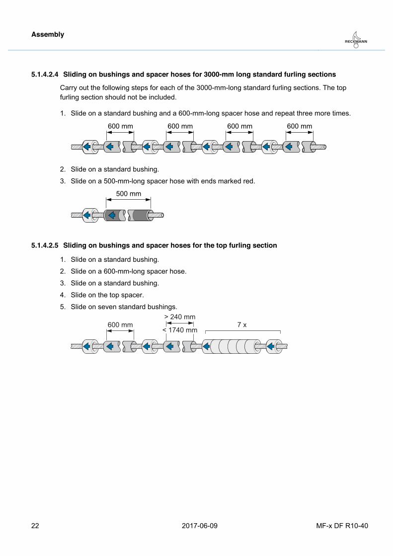
5.1.4.2.4 Sliding on bushings and spacer hoses for 3000-mm long standard furling sections
Carry out the following steps for each of the 3000-mm-long standard furling sections. The top furling section should not be included.
1. Slide on a standard bushing and a 600-mm-long spacer hose and repeat three more times.
2. Slide on a standard bushing.
3. Slide on a 500-mm-long spacer hose with ends marked red.
5.1.4.2.5 Sliding on bushings and spacer hoses for the top furling section
1. Slide on a standard bushing.
2. Slide on a 600-mm-long spacer hose.
3. Slide on a standard bushing.
4. Slide on the top spacer.
5. Slide on seven standard bushings.
600 mm> 240 mm
< 1740 mm7 x
Pos: 33 /ZINDEL/Rollreffanlagen/Montage/Alu/R10 - R40/wire/Terminal auf Drahtvorstag montieren R10-R40 @ 1\mod_1399872745049_26.docx @ 9691 @ 4 @ 1
Assembly
MF-x DF R10-40 2017-06-09 23
5.1.4.3 Installing the top terminal on the wire forestay
Warning Risk of breaking the forestay − The top terminal must be fitted by qualified personnel using suitable tools.
Notice Once the terminal has been installed on the wire forestay, bushings or spacer hoses can no longer be fitted. Only install the terminal after ensuring that all bushings and spacer hoses have been properly installed.
− Roller-swage the terminal on to the wire forestay
or:
− Install a swageless stud terminal according to the supplied assembly instructions. Pos: 34 /ZINDEL/Rollreffanlagen/Montage/MF-x DF/headline_Decksflansch montieren @ 1\mod_1487687348339_26.docx @ 18036 @ 2 @ 1
5.2 Installing the deck flange Pos: 35 /ZINDEL/Rollreffanlagen/Montage/MF-x DF/Übersicht Decksflansch montieren @ 1\mod_1478167192996_26.docx @ 17472 @ 3 @ 1
5.2.1 Overview of the installation steps
Caution Material damage from an incorrectly positioned bore hole in the deck and incorrect installation Any incorrectly positioned bore hole leads to heavy wear of the system and the assemblies connected to the system. Any repair would incur high costs. − Drill the hole properly, involve an experienced boat-builder where possible. − Carry out all installation steps correctly and with great care.
− Making a hole in the deck: → page 24
− Provisional setting of the length of the drum bearing unit: → page 25
− Provisional connection of the forestay to the drum bearing unit. Rod forestay: → page 28, wire forestay: → page 29
− Provisional hoisting of the system: → page 30
− Provisional setting of the forestay length: → page 31
− Checking the gap dimension in the deck hole and adjusting if necessary: → page 33
− Laying on the deck flange and underpinning if necessary: → page 34
− Screwing on the deck flange: → page 36
Proceed very carefully and deliberately with all steps. Pos: 36 /ZINDEL/Rollreffanlagen/Montage/MF-x DF/Loch bohren bei Montage Decksflansch @ 1\mod_1480426286695_26.docx @ 17816 @ 3 @ 1
Assembly
24 2017-06-09 MF-x DF R10-40
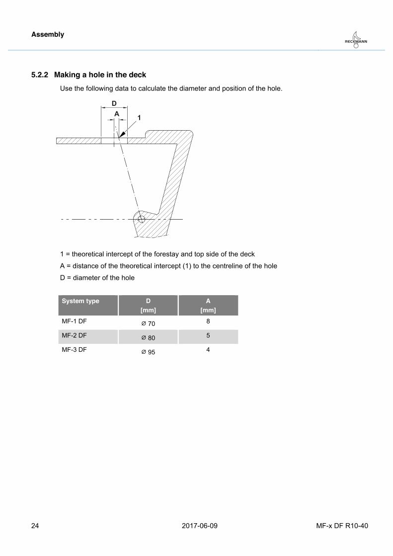
5.2.2 Making a hole in the deck Use the following data to calculate the diameter and position of the hole.
DA 1
1 = theoretical intercept of the forestay and top side of the deck
A = distance of the theoretical intercept (1) to the centreline of the hole
D = diameter of the hole
System type D
[mm] A
[mm] MF-1 DF ⌀ 70 8
MF-2 DF ⌀ 80 5
MF-3 DF ⌀ 95 4
Pos: 37 /ZINDEL/Rollreffanlagen/Montage/MF-x DF/Länge Trommeleinheit einstellen @ 1\mod_1480426382319_26.docx @ 17826 @ 3 @ 1
Assembly
MF-x DF R10-40 2017-06-09 25
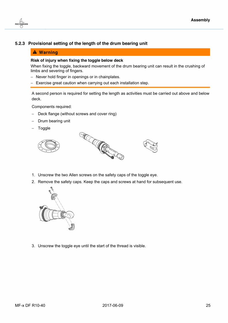
5.2.3 Provisional setting of the length of the drum bearing unit
Warning Risk of injury when fixing the toggle below deck When fixing the toggle, backward movement of the drum bearing unit can result in the crushing of limbs and severing of fingers. − Never hold finger in openings or in chainplates. − Exercise great caution when carrying out each installation step.
A second person is required for setting the length as activities must be carried out above and below deck.
Components required:
− Deck flange (without screws and cover ring)
− Drum bearing unit
− Toggle
1. Unscrew the two Allen screws on the safety caps of the toggle eye.
2. Remove the safety caps. Keep the caps and screws at hand for subsequent use.
3. Unscrew the toggle eye until the start of the thread is visible.
Assembly
26 2017-06-09 MF-x DF R10-40
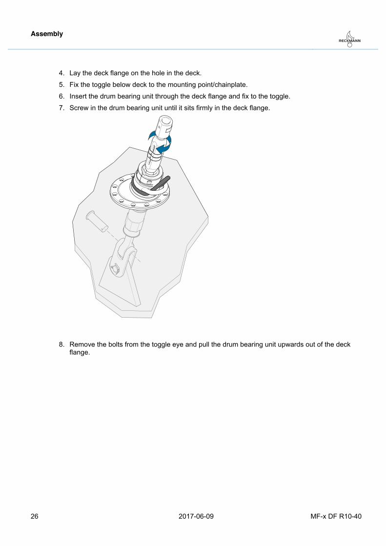
4. Lay the deck flange on the hole in the deck.
5. Fix the toggle below deck to the mounting point/chainplate.
6. Insert the drum bearing unit through the deck flange and fix to the toggle.
7. Screw in the drum bearing unit until it sits firmly in the deck flange.
8. Remove the bolts from the toggle eye and pull the drum bearing unit upwards out of the deck flange.
Assembly
MF-x DF R10-40 2017-06-09 27
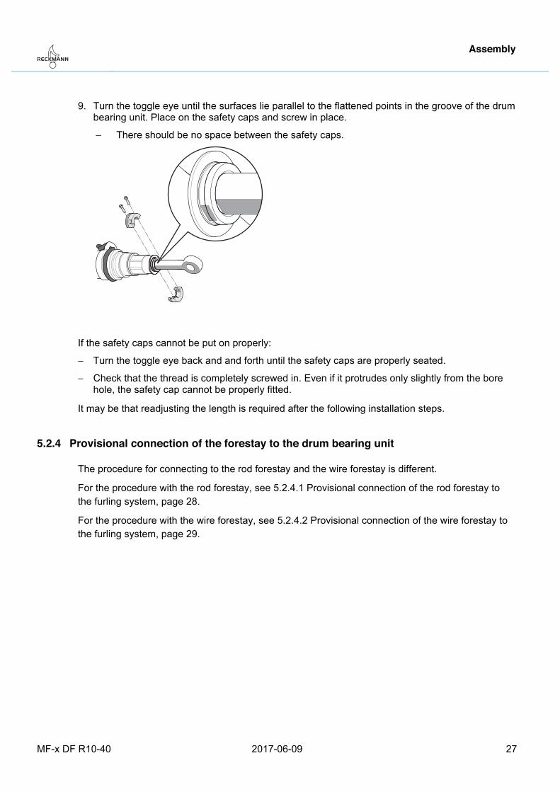
9. Turn the toggle eye until the surfaces lie parallel to the flattened points in the groove of the drum bearing unit. Place on the safety caps and screw in place.
− There should be no space between the safety caps.
If the safety caps cannot be put on properly:
− Turn the toggle eye back and and forth until the safety caps are properly seated.
− Check that the thread is completely screwed in. Even if it protrudes only slightly from the bore hole, the safety cap cannot be properly fitted.
It may be that readjusting the length is required after the following installation steps. Pos: 38 /ZINDEL/Rollreffanlagen/Montage/MF-x DF/Vorstag vorläufig mit RR-Anlage verbinden MF-x DF fuer Montage DF @ 1\mod_1488378504486_26.docx @ 18216 @ 3 @ 1
5.2.4 Provisional connection of the forestay to the drum bearing unit
The procedure for connecting to the rod forestay and the wire forestay is different.
For the procedure with the rod forestay, see 5.2.4.1 Provisional connection of the rod forestay to the furling system, page 28.
For the procedure with the wire forestay, see 5.2.4.2 Provisional connection of the wire forestay to the furling system, page 29.
Pos: 39 /ZINDEL/Rollreffanlagen/Montage/MF-x DF/Rodvorstag mit RR-Anlage verbinden MF-x DF fuer Montage DF @ 1\mod_1480680545740_26.docx @ 17886 @ 4 @ 1
Assembly
28 2017-06-09 MF-x DF R10-40
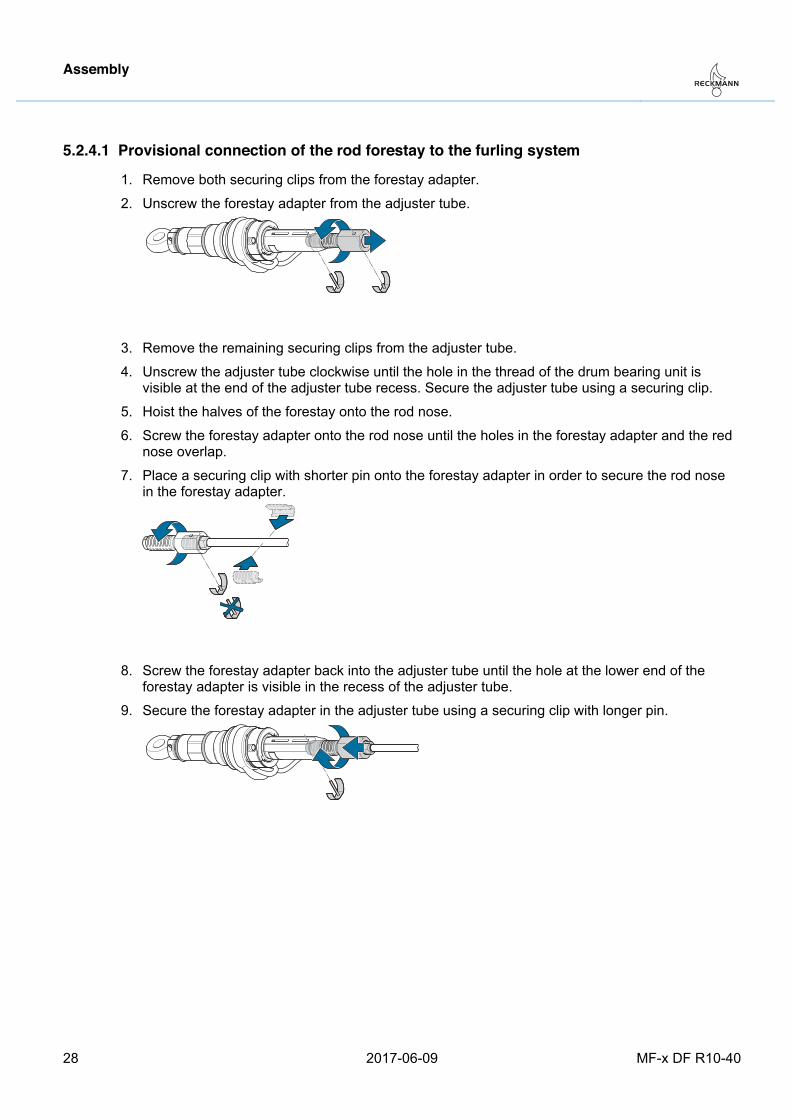
5.2.4.1 Provisional connection of the rod forestay to the furling system
1. Remove both securing clips from the forestay adapter.
2. Unscrew the forestay adapter from the adjuster tube.
3. Remove the remaining securing clips from the adjuster tube.
4. Unscrew the adjuster tube clockwise until the hole in the thread of the drum bearing unit is visible at the end of the adjuster tube recess. Secure the adjuster tube using a securing clip.
5. Hoist the halves of the forestay onto the rod nose.
6. Screw the forestay adapter onto the rod nose until the holes in the forestay adapter and the red nose overlap.
7. Place a securing clip with shorter pin onto the forestay adapter in order to secure the rod nose in the forestay adapter.
8. Screw the forestay adapter back into the adjuster tube until the hole at the lower end of the forestay adapter is visible in the recess of the adjuster tube.
9. Secure the forestay adapter in the adjuster tube using a securing clip with longer pin.
Pos: 40 /ZINDEL/Rollreffanlagen/Montage/MF-x DF/Drahtvorstag mit RR-Anlage verbinden MF-x DF für Montage DF @ 1\mod_1480680590577_26.docx @ 17891 @ 4 @ 1
Assembly
MF-x DF R10-40 2017-06-09 29
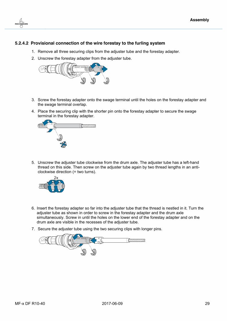
5.2.4.2 Provisional connection of the wire forestay to the furling system
1. Remove all three securing clips from the adjuster tube and the forestay adapter.
2. Unscrew the forestay adapter from the adjuster tube.
3. Screw the forestay adapter onto the swage terminal until the holes on the forestay adapter and the swage terminal overlap.
4. Place the securing clip with the shorter pin onto the forestay adapter to secure the swage terminal in the forestay adapter.
5. Unscrew the adjuster tube clockwise from the drum axle. The adjuster tube has a left-hand thread on this side. Then screw on the adjuster tube again by two thread lengths in an anti-clockwise direction (= two turns).
2x
6. Insert the forestay adapter so far into the adjuster tube that the thread is nestled in it. Turn the adjuster tube as shown in order to screw in the forestay adapter and the drum axle simultaneously. Screw in until the holes on the lower end of the forestay adapter and on the drum axle are visible in the recesses of the adjuster tube.
7. Secure the adjuster tube using the two securing clips with longer pins.
Pos: 41 /ZINDEL/Rollreffanlagen/Montage/MF-x DF/Anlage setzen testweise MF-x DF @ 1\mod_1480680959918_26.docx @ 17896 @ 3 @ 1
Assembly
30 2017-06-09 MF-x DF R10-40
5.2.5 Provisional hoisting of the system
Warning Risk of forestay breakage The forestay is subject to high bending moments when there is no mast toggle mounted. If the forestay breaks, severe injuries may result. − Use a mast toggle (not included in the scope of delivery).
Warning Shear and crushing hazard on bolt holes Fingers may be sheared off in the bolt holes. − Never stick your finger into a bolt hole.
Prerequisites:
− The drum bearing unit is set to the right length.
− The forestay is connected to the drum bearing unit.
Do not use the deck flange for the following steps.
1. Connect the forestay to the mast toggle.
2. Fasten the drum bearing unit below deck to the chainplate and secure the toggle bolts with splints.
The system is now provisionally hoisted.
The forestay length is provisionally set in the next step. Pos: 42 /ZINDEL/Rollreffanlagen/Montage/MF-x DF/Vorstaglänge einstellen testweise MF-x DF @ 1\mod_1480684223925_26.docx @ 17901 @ 3 @ 1
Assembly
MF-x DF R10-40 2017-06-09 31
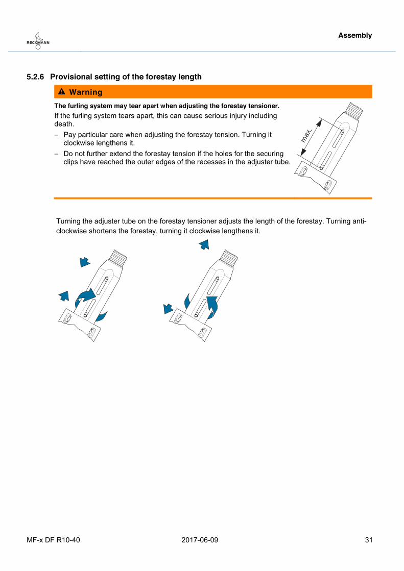
5.2.6 Provisional setting of the forestay length
Warning The furling system may tear apart when adjusting the forestay tensioner. If the furling system tears apart, this can cause serious injury including death. − Pay particular care when adjusting the forestay tension. Turning it
clockwise lengthens it. − Do not further extend the forestay tension if the holes for the securing
clips have reached the outer edges of the recesses in the adjuster tube.
max
.
Turning the adjuster tube on the forestay tensioner adjusts the length of the forestay. Turning anti-clockwise shortens the forestay, turning it clockwise lengthens it.
Assembly
32 2017-06-09 MF-x DF R10-40
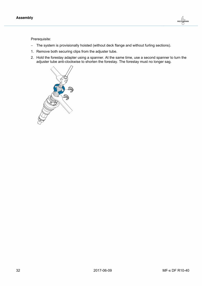
Prerequisite:
− The system is provisionally hoisted (without deck flange and without furling sections).
1. Remove both securing clips from the adjuster tube.
2. Hold the forestay adapter using a spanner. At the same time, use a second spanner to turn the adjuster tube anti-clockwise to shorten the forestay. The forestay must no longer sag.
Pos: 43 /ZINDEL/Rollreffanlagen/Montage/MF-x DF/Spaltmaß prüfen bei Montage Decksflansch @ 1\mod_1480426385502_26.docx @ 17831 @ 3 @ 1
Assembly
MF-x DF R10-40 2017-06-09 33
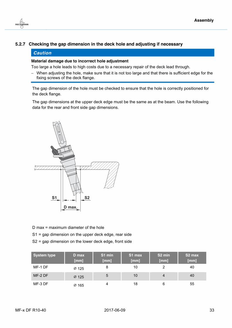
5.2.7 Checking the gap dimension in the deck hole and adjusting if necessary
Caution Material damage due to incorrect hole adjustment Too large a hole leads to high costs due to a necessary repair of the deck lead through. − When adjusting the hole, make sure that it is not too large and that there is sufficient edge for the
fixing screws of the deck flange.
The gap dimension of the hole must be checked to ensure that the hole is correctly positioned for the deck flange.
The gap dimensions at the upper deck edge must be the same as at the beam. Use the following data for the rear and front side gap dimensions.
S1 S2
D max.
D max = maximum diameter of the hole
S1 = gap dimension on the upper deck edge, rear side
S2 = gap dimension on the lower deck edge, front side
System type D max
[mm] S1 min [mm]
S1 max [mm]
S2 min [mm]
S2 max [mm]
MF-1 DF ⌀ 125 8 10 2 40
MF-2 DF ⌀ 125 5 10 4 40
MF-3 DF ⌀ 165 4 18 6 55
Assembly
34 2017-06-09 MF-x DF R10-40
Prerequisites:
− The system is provisionally hoisted (without furling sections).
− The forestay is adjusted so that it does not sag.
1. Check the gap dimensions of the hole around the drum bearing unit.
2. Set the forestay to maximum length. Turn the adjuster tube clockwise for this. Secure the adjuster tube using securing clips.
3. Remove the system from the toggle from below and pull it out of the hole.
4. If the gap dimensions were not correct, adjust the hole size very carefully.
5. After adjusting the hole, put the system back on and re-adjust the correct forestay length. Check the gap dimensions again.
6. If the dimensions are okay, set the forestay back to the maximum length and secure the adjuster tube with the securing clips.
7. Remove the system from the toggle from below and pull it out of the hole.
The system can remain fitted to the mast for the following steps Pos: 44 /ZINDEL/Rollreffanlagen/Montage/MF-x DF/Decksflansch anlegen und unterfüttern @ 1\mod_1480426388815_26.docx @ 17836 @ 3 @ 1
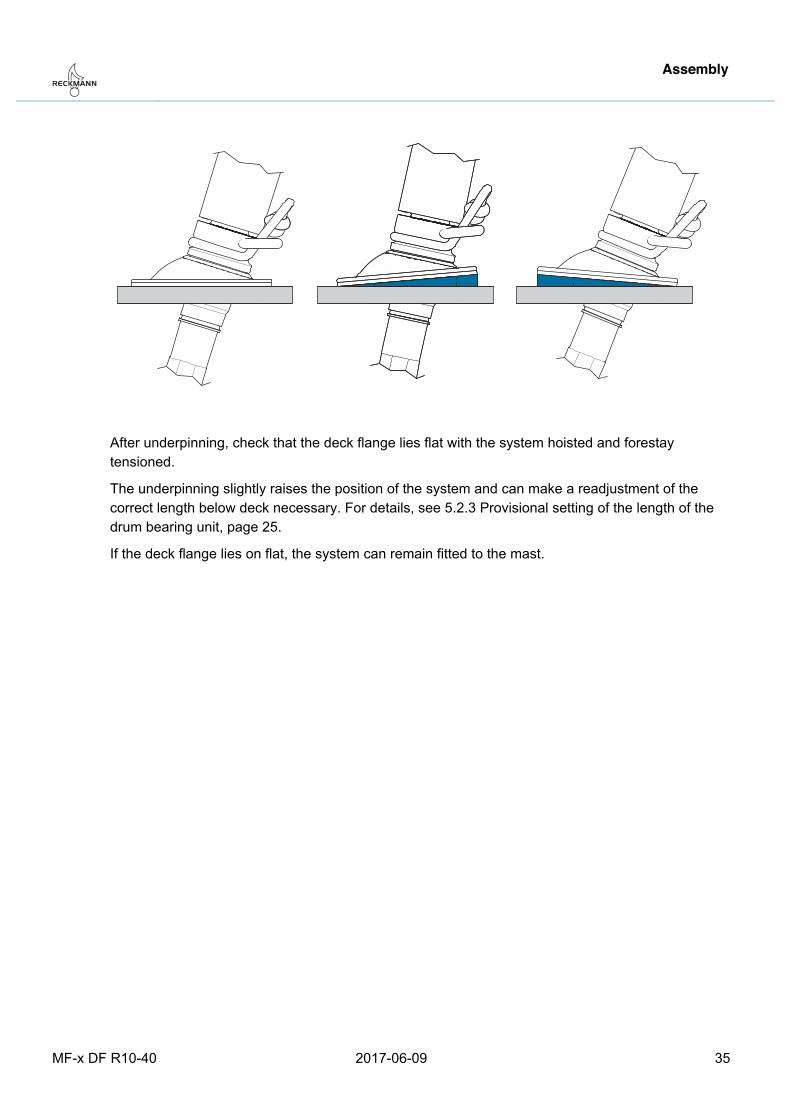
5.2.8 Laying on the deck flange and underpinning if necessary To ensure that the deck flange lies on correctly and can be fitted, check that the flange lies level on the deck with the forestay tensioned. Otherwise transverse forces occur that lead to stiffness and increased wear of the system and the connected components.
Caution Material damage due to incorrect installation of the deck flange − Do NOT yet drill the holes for the fixing screws in this installation step! The deck flange is only
placed on but not fitted. − Only have the underpinning of the deck flange carried out by an experienced boat builder.
Prerequisite:
− Forestay with drum bearing unit fitted to the mast
1. Lay the deck flange on the hole.
2. Insert the drum bearing unit through the deck flange and fix to the toggle.
3. Adjust the forestay length so that the forestay does not sag.
4. Check that the deck flange sits flat on the deck or if there is a gap between the flange and the deck.
5. Remove the drum bearing unit from the toggle and pull it out.
6. To compensate for a gap, underpin the flange properly.
Assembly
MF-x DF R10-40 2017-06-09 35
After underpinning, check that the deck flange lies flat with the system hoisted and forestay tensioned.
The underpinning slightly raises the position of the system and can make a readjustment of the correct length below deck necessary. For details, see 5.2.3 Provisional setting of the length of the drum bearing unit, page 25.
If the deck flange lies on flat, the system can remain fitted to the mast.
Pos: 45 /ZINDEL/Rollreffanlagen/Montage/MF-x DF/Befestigungslöcher bohren bei Montage Decksflansch @ 1\mod_1480426379518_26.docx @ 17821 @ 3 @ 1
Assembly
36 2017-06-09 MF-x DF R10-40
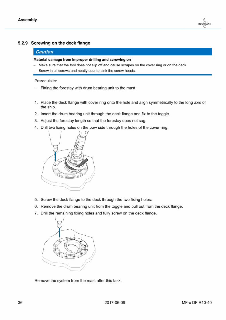
5.2.9 Screwing on the deck flange
Caution Material damage from improper drilling and screwing on − Make sure that the tool does not slip off and cause scrapes on the cover ring or on the deck. − Screw in all screws and neatly countersink the screw heads.
Prerequisite:
− Fitting the forestay with drum bearing unit to the mast
1. Place the deck flange with cover ring onto the hole and align symmetrically to the long axis of the ship.
2. Insert the drum bearing unit through the deck flange and fix to the toggle.
3. Adjust the forestay length so that the forestay does not sag.
4. Drill two fixing holes on the bow side through the holes of the cover ring.
5. Screw the deck flange to the deck through the two fixing holes.
6. Remove the drum bearing unit from the toggle and pull out from the deck flange.
7. Drill the remaining fixing holes and fully screw on the deck flange.
Remove the system from the mast after this task.
Pos: 46 /ZINDEL/Rollreffanlagen/Montage/MF-x DF/Vorstag von Vorstagadapter trennen_MF_DF @ 1\mod_1488210291154_26.docx @ 18086 @ 2 @ 1
Assembly
MF-x DF R10-40 2017-06-09 37
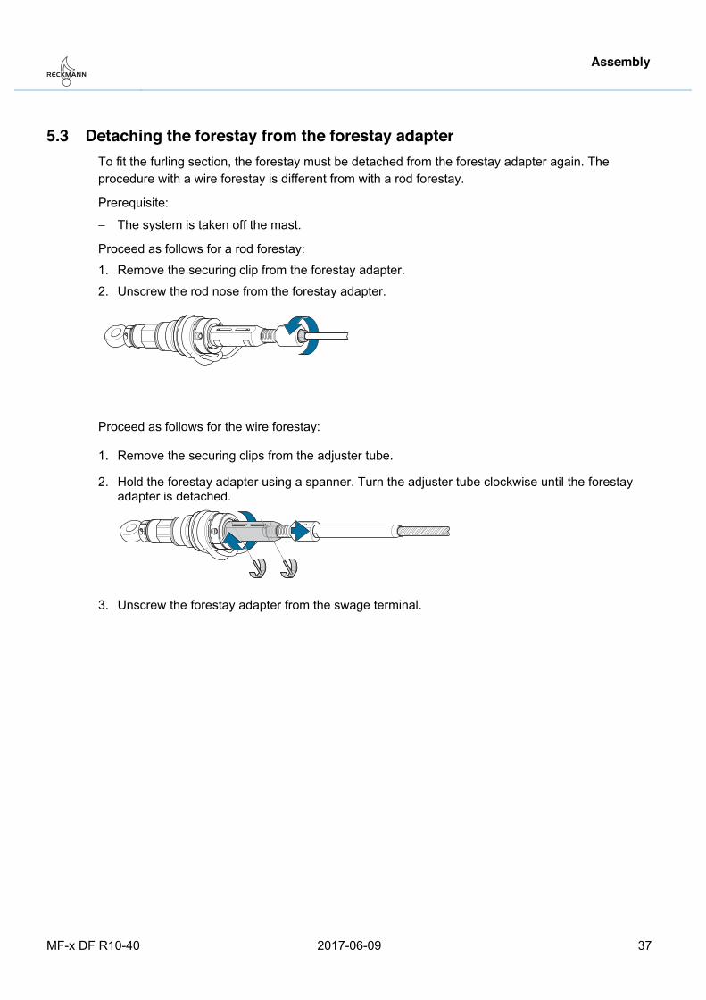
5.3 Detaching the forestay from the forestay adapter To fit the furling section, the forestay must be detached from the forestay adapter again. The procedure with a wire forestay is different from with a rod forestay.
Prerequisite:
− The system is taken off the mast.
Proceed as follows for a rod forestay:
1. Remove the securing clip from the forestay adapter.
2. Unscrew the rod nose from the forestay adapter.
Proceed as follows for the wire forestay:
1. Remove the securing clips from the adjuster tube.
2. Hold the forestay adapter using a spanner. Turn the adjuster tube clockwise until the forestay adapter is detached.
3. Unscrew the forestay adapter from the swage terminal.
Pos: 47 /ZINDEL/Rollreffanlagen/Montage/Alu/R10 - R40/Profile montieren_MF @ 1\mod_1444058079896_26.docx @ 15961 @ 2 @ 1
Assembly
38 2017-06-09 MF-x DF R10-40
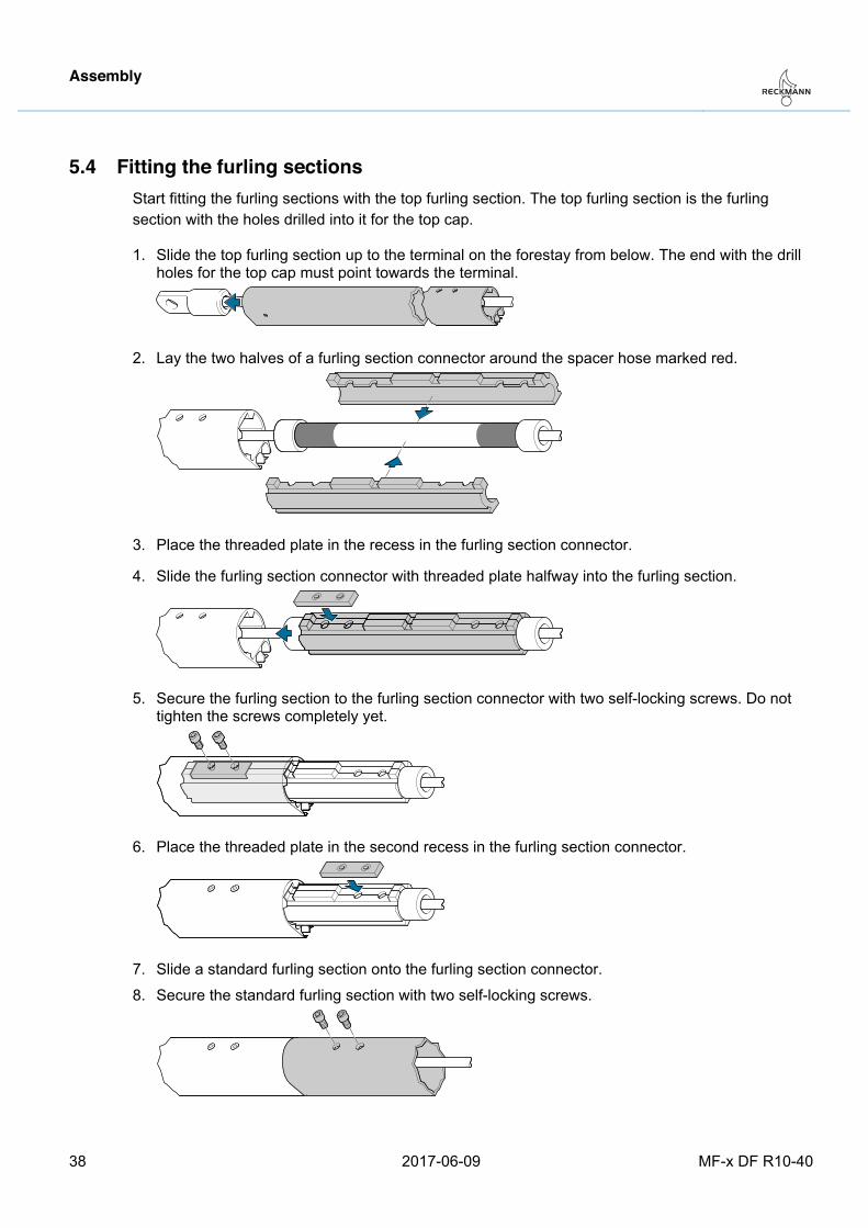
5.4 Fitting the furling sections Start fitting the furling sections with the top furling section. The top furling section is the furling section with the holes drilled into it for the top cap.
1. Slide the top furling section up to the terminal on the forestay from below. The end with the drill holes for the top cap must point towards the terminal.
2. Lay the two halves of a furling section connector around the spacer hose marked red.
3. Place the threaded plate in the recess in the furling section connector.
4. Slide the furling section connector with threaded plate halfway into the furling section.
5. Secure the furling section to the furling section connector with two self-locking screws. Do not tighten the screws completely yet.
6. Place the threaded plate in the second recess in the furling section connector.
7. Slide a standard furling section onto the furling section connector.
8. Secure the standard furling section with two self-locking screws.
Assembly
MF-x DF R10-40 2017-06-09 39
9. When all four screw threads are engaged in the tapped holes in the threaded plate, tighten the screws.
10. Repeat steps 2 to 9 with other furling sections in the following order:
• 3000-mm-long standard furling sections
• 1500-mm-long standard furling section (if present).
11. Repeat steps 2 to 5 for the feeder section. If no furling section reinforcement is to be fitted later, also repeat steps 6 to 9 with the feeder section.
Pos: 48 /ZINDEL/Rollreffanlagen/Montage/Alu/R10 - R40/Buchsen-Stopper montieren_MF @ 1\mod_1467196410358_26.docx @ 17174 @ 2 @ 1
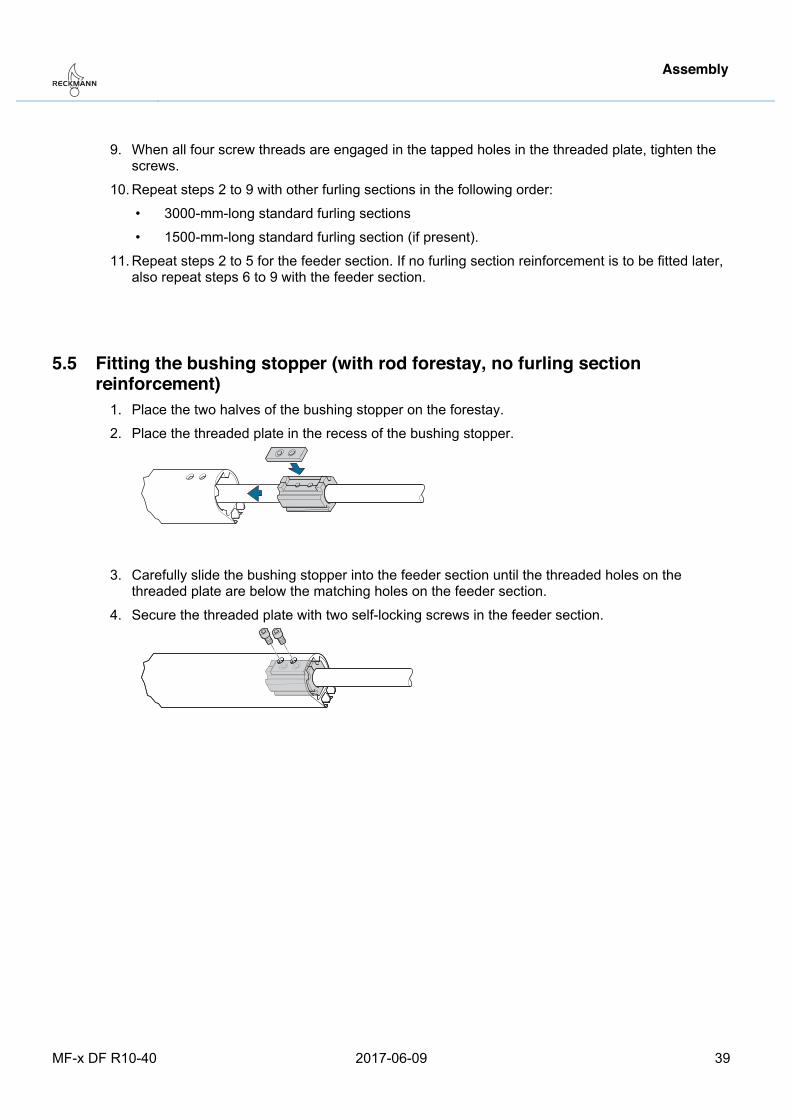
5.5 Fitting the bushing stopper (with rod forestay, no furling section reinforcement)
1. Place the two halves of the bushing stopper on the forestay.
2. Place the threaded plate in the recess of the bushing stopper.
3. Carefully slide the bushing stopper into the feeder section until the threaded holes on the threaded plate are below the matching holes on the feeder section.
4. Secure the threaded plate with two self-locking screws in the feeder section.
Pos: 49 /ZINDEL/Rollreffanlagen/Montage/Alu/R10 - R40/Profilverstärkung montieren_MF @ 1\mod_1444061680259_26.docx @ 15966 @ 2 @ 1
Assembly
40 2017-06-09 MF-x DF R10-40
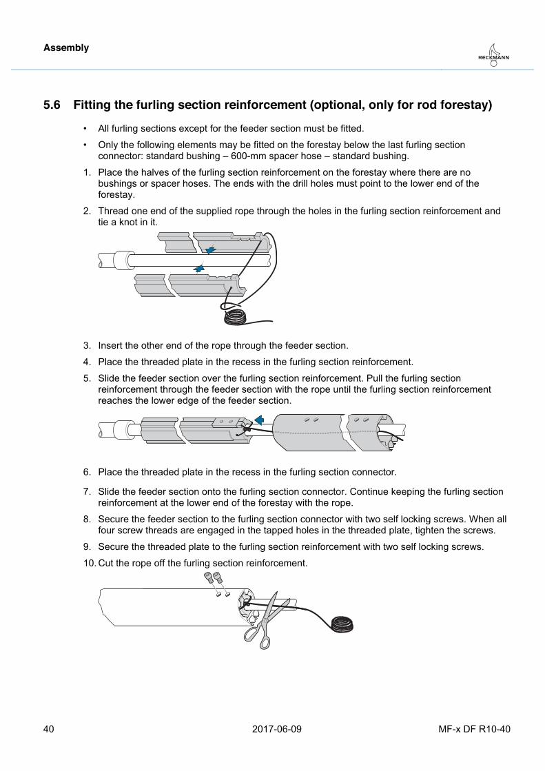
5.6 Fitting the furling section reinforcement (optional, only for rod forestay)
• All furling sections except for the feeder section must be fitted.
• Only the following elements may be fitted on the forestay below the last furling section connector: standard bushing – 600-mm spacer hose – standard bushing.
1. Place the halves of the furling section reinforcement on the forestay where there are no bushings or spacer hoses. The ends with the drill holes must point to the lower end of the forestay.
2. Thread one end of the supplied rope through the holes in the furling section reinforcement and tie a knot in it.
3. Insert the other end of the rope through the feeder section.
4. Place the threaded plate in the recess in the furling section reinforcement.
5. Slide the feeder section over the furling section reinforcement. Pull the furling section reinforcement through the feeder section with the rope until the furling section reinforcement reaches the lower edge of the feeder section.
6. Place the threaded plate in the recess in the furling section connector.
7. Slide the feeder section onto the furling section connector. Continue keeping the furling section reinforcement at the lower end of the forestay with the rope.
8. Secure the feeder section to the furling section connector with two self locking screws. When all four screw threads are engaged in the tapped holes in the threaded plate, tighten the screws.
9. Secure the threaded plate to the furling section reinforcement with two self locking screws.
10. Cut the rope off the furling section reinforcement.
Pos: 50 /ZINDEL/Rollreffanlagen/Montage/Alu/R10 - R40/Segeleinführer und Fallenschlitten montieren MF @ 1\mod_1444315565370_26.docx @ 16010 @ 2 @ 1
Assembly
MF-x DF R10-40 2017-06-09 41
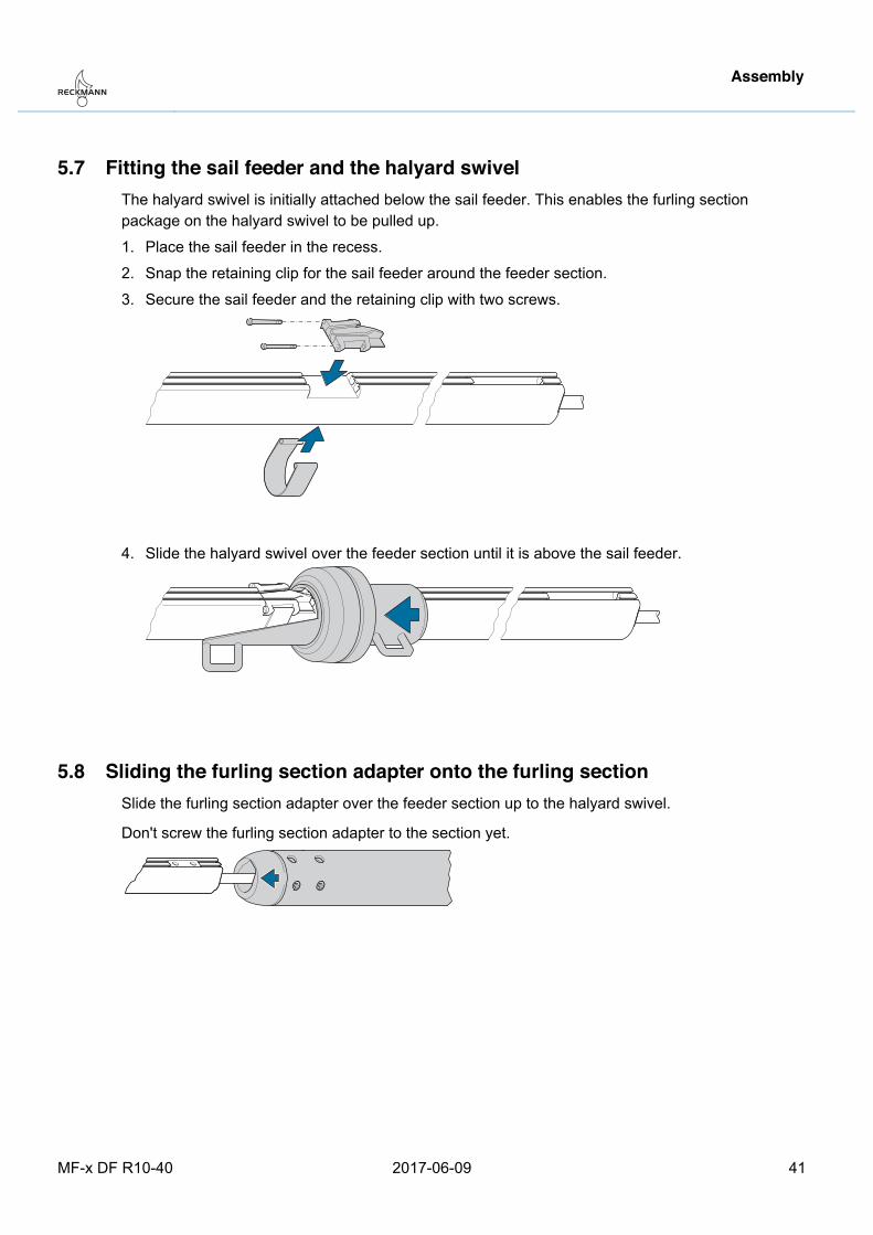
5.7 Fitting the sail feeder and the halyard swivel The halyard swivel is initially attached below the sail feeder. This enables the furling section package on the halyard swivel to be pulled up.
1. Place the sail feeder in the recess.
2. Snap the retaining clip for the sail feeder around the feeder section.
3. Secure the sail feeder and the retaining clip with two screws.
4. Slide the halyard swivel over the feeder section until it is above the sail feeder.
Pos: 51 /ZINDEL/Rollreffanlagen/Montage/MF/Profiladapter auf Profil schieben @ 1\mod_1444316679970_26.docx @ 16014 @ 2 @ 1
5.8 Sliding the furling section adapter onto the furling section Slide the furling section adapter over the feeder section up to the halyard swivel.
Don't screw the furling section adapter to the section yet.
Pos: 52 /ZINDEL/Rollreffanlagen/Montage/MF-x DF/headline_Vorstag endgültig mit Rollreffanlage verbinden @ 1\mod_1488264954896_26.docx @ 18101 @ 2 @ 1
Assembly
42 2017-06-09 MF-x DF R10-40
5.9 Finally connecting the forestay to the furling system Warning
The furling system may loosen if the securing clips are improperly fitted. If the furling system unscrews and becomes loose, this can lead to serious injury including death. − Only use a securing clip with a shorter pin to secure the rod nose or the swage terminal in the
forestay adapter. − Only use the securing clips with longer pins to secure the adjuster tube. − Following installation of the securing clips, check that all three securing clips are properly seated.
The procedure for the rod forestay and the wire forestay is different.
5.9.1 Finally connecting the rod forestay to the furling system, page 42
5.9.2 Finally connecting the wire forestay to the furling system, page 43
Pos: 53 /ZINDEL/Rollreffanlagen/Montage/MF-x DF/Rodvorstag mit Rollreffanlage verbinden MF-x DF @ 1\mod_1478529527865_26.docx @ 17676 @ 3 @ 1
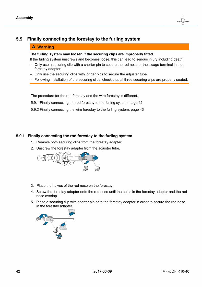
5.9.1 Finally connecting the rod forestay to the furling system 1. Remove both securing clips from the forestay adapter.
2. Unscrew the forestay adapter from the adjuster tube.
3. Place the halves of the rod nose on the forestay.
4. Screw the forestay adapter onto the rod nose until the holes in the forestay adapter and the rednose overlap.
5. Place a securing clip with shorter pin onto the forestay adapter in order to secure the rod nosein the forestay adapter.
Assembly
MF-x DF R10-40 2017-06-09 43
6. Screw the forestay adapter back into the adjuster tube until the hole at the lower end of theforestay adapter is visible in the recess of the adjuster tube.
7. Secure the forestay adapter in the adjuster tube using a securing clip with longer pin.
Pos: 54 /ZINDEL/Rollreffanlagen/Montage/MF-x DF/Drahtvorstag mit Rollreffanlage verbinden MF-x DF @ 1\mod_1478529865143_26.docx @ 17681 @ 3 @ 1
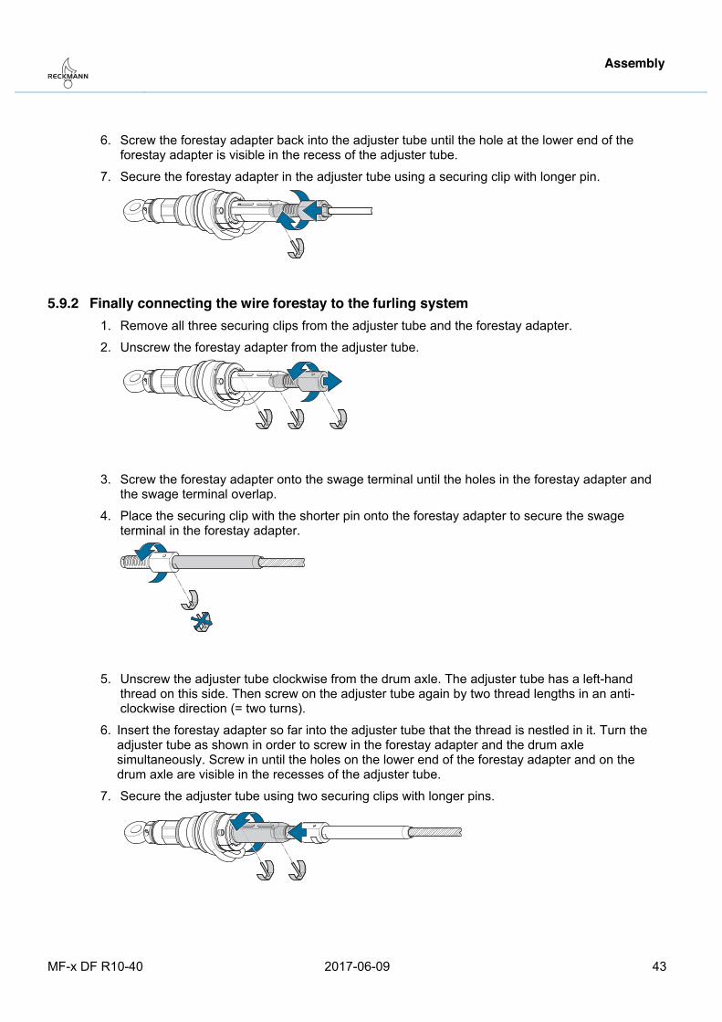
5.9.2 Finally connecting the wire forestay to the furling system 1. Remove all three securing clips from the adjuster tube and the forestay adapter.
2. Unscrew the forestay adapter from the adjuster tube.
3. Screw the forestay adapter onto the swage terminal until the holes in the forestay adapter andthe swage terminal overlap.
4. Place the securing clip with the shorter pin onto the forestay adapter to secure the swageterminal in the forestay adapter.
5. Unscrew the adjuster tube clockwise from the drum axle. The adjuster tube has a left-handthread on this side. Then screw on the adjuster tube again by two thread lengths in an anti-clockwise direction (= two turns).
6. Insert the forestay adapter so far into the adjuster tube that the thread is nestled in it. Turn theadjuster tube as shown in order to screw in the forestay adapter and the drum axlesimultaneously. Screw in until the holes on the lower end of the forestay adapter and on thedrum axle are visible in the recesses of the adjuster tube.
7. Secure the adjuster tube using two securing clips with longer pins.
Pos: 55 /ZINDEL/Rollreffanlagen/Montage/MF-x DF/Profiladapter an Profil montieren @ 1\mod_1488380787094_26.docx @ 18221 @ 2 @ 1
Assembly
44 2017-06-09 MF-x DF R10-40
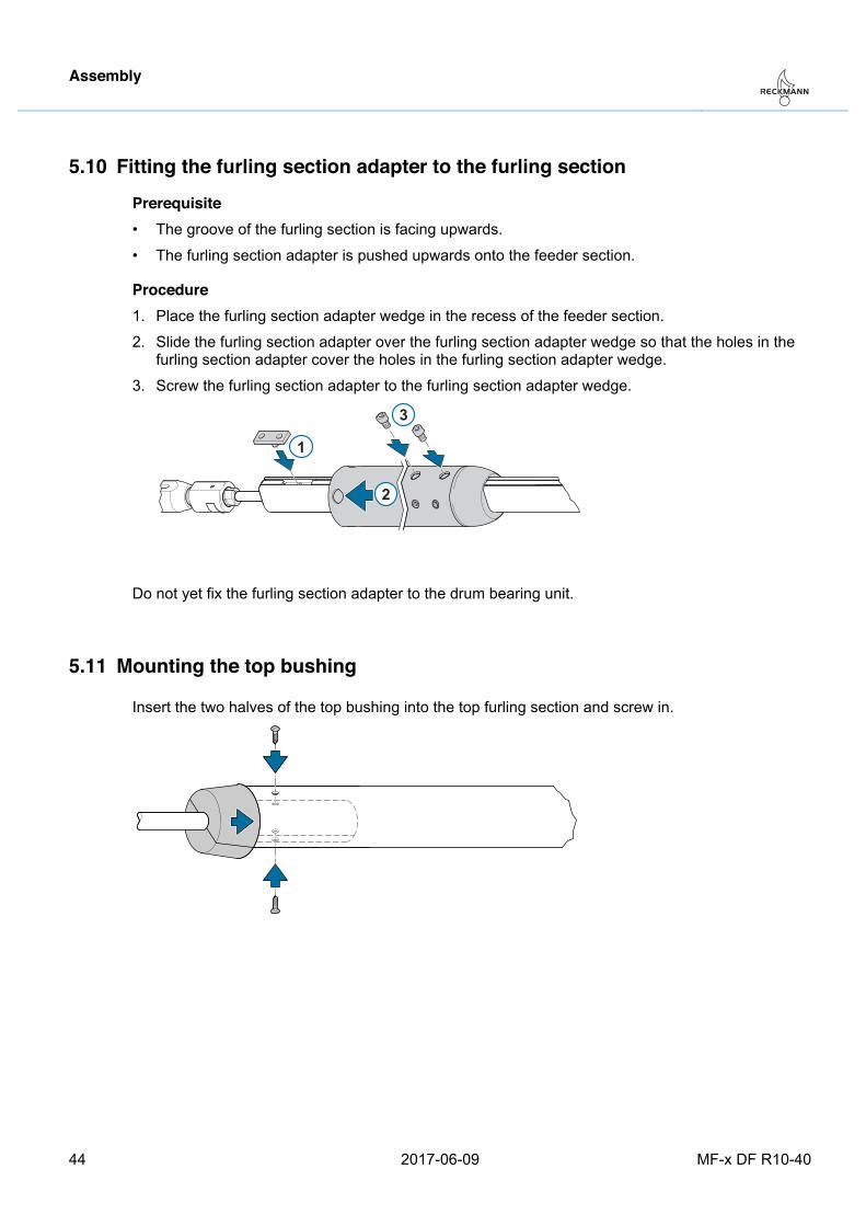
5.10 Fitting the furling section adapter to the furling section
Prerequisite • The groove of the furling section is facing upwards.
• The furling section adapter is pushed upwards onto the feeder section.
Procedure 1. Place the furling section adapter wedge in the recess of the feeder section.
2. Slide the furling section adapter over the furling section adapter wedge so that the holes in the furling section adapter cover the holes in the furling section adapter wedge.
3. Screw the furling section adapter to the furling section adapter wedge.
2
3
1
Do not yet fix the furling section adapter to the drum bearing unit. Pos: 56 /ZINDEL/Rollreffanlagen/Montage/Alu/Topbuchse montieren @ 1\mod_1400841178465_26.docx @ 10043 @ 2 @ 1
5.11 Mounting the top bushing
Insert the two halves of the top bushing into the top furling section and screw in.
Pos: 57 /ZINDEL/Rollreffanlagen/Montage/MF-x DF/headline_Anlage endgültig setzen_ohne-WaHi @ 1\mod_1488267352834_26.docx @ 18110 @ 2 @ 1
Assembly
MF-x DF R10-40 2017-06-09 45
5.12 Finally hoisting the system Pos: 58 /ZINDEL/Rollreffanlagen/Montage/Toggle Masttop @ 1\mod_1400825458562_26.docx @ 10033 @ 3 @ 1
5.12.1 Toggle on the masthead
Warning Risk of forestay breakage The forestay is subject to high bending moments when there is no mast toggle fitted. If the forestay breaks, severe injury can result. − Connect the forestay to the mast with a mast toggle.
Pos: 59 /ZINDEL/Rollreffanlagen/Montage/MF-x DF/Anlage am Toggle befestigen @ 1\mod_1488267970440_26.docx @ 18115 @ 3 @ 1
5.12.2 Fixing the system to the toggle
Warning The furling system can tear apart if improperly secured. If the furling system tears apart, this can lead to serious injury including death. − Secure the toggle bolts using splint pins. Bend the splint pins well apart. − Do no reuse splint pins.
Warning Shear and crushing hazard on bolt holes Fingers may be sheared off in the bolt holes. − Never stick your finger into a bolt hole.
1. Insert the drum bearing unit through the deck flange.
2. Fix the toggle eye to the toggle.
3. Secure the toggle bolt using a splint pin.
Pos: 60 /ZINDEL/Rollreffanlagen/Montage/MF-x DF/Vorstaglänge einstellen MF-x DF @ 1\mod_1478531093302_26.docx @ 17696 @ 2 @ 1
Assembly
46 2017-06-09 MF-x DF R10-40
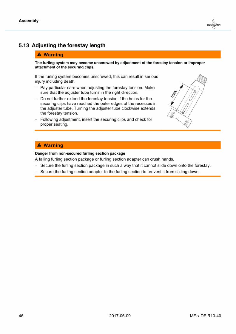
5.13 Adjusting the forestay length Warning
The furling system may become unscrewed by adjustment of the forestay tension or improper attachment of the securing clips.
If the furling system becomes unscrewed, this can result in serious injury including death. − Pay particular care when adjusting the forestay tension. Make
sure that the adjuster tube turns in the right direction. − Do not further extend the forestay tension if the holes for the
securing clips have reached the outer edges of the recesses in the adjuster tube. Turning the adjuster tube clockwise extends the forestay tension.
− Following adjustment, insert the securing clips and check for proper seating.
max
.
Warning Danger from non-secured furling section package A falling furling section package or furling section adapter can crush hands. − Secure the furling section package in such a way that it cannot slide down onto the forestay. − Secure the furling section adapter to the furling section to prevent it from sliding down.
Assembly
MF-x DF R10-40 2017-06-09 47
Prerequisite:
− The system is hoisted.
− The halyard swivel is below the sail feeder.
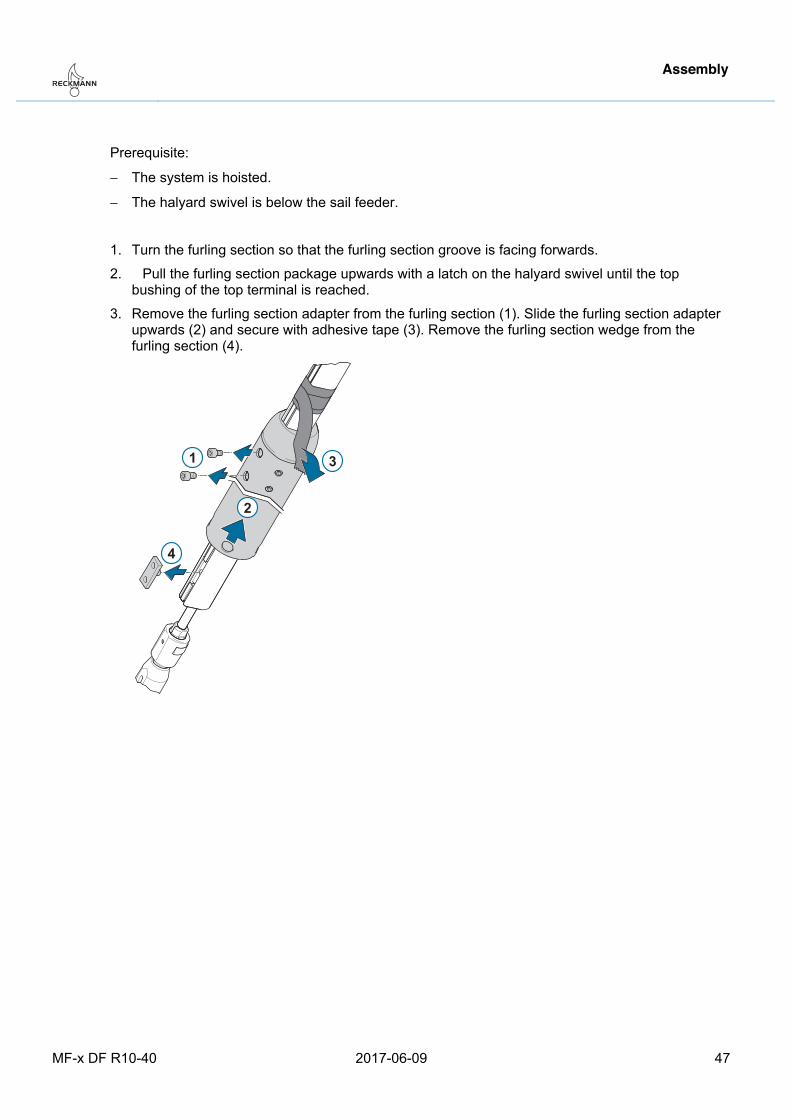
1. Turn the furling section so that the furling section groove is facing forwards.
2. Pull the furling section package upwards with a latch on the halyard swivel until the top bushing of the top terminal is reached.
3. Remove the furling section adapter from the furling section (1). Slide the furling section adapter upwards (2) and secure with adhesive tape (3). Remove the furling section wedge from the furling section (4).
1
2
3
4
Assembly
48 2017-06-09 MF-x DF R10-40
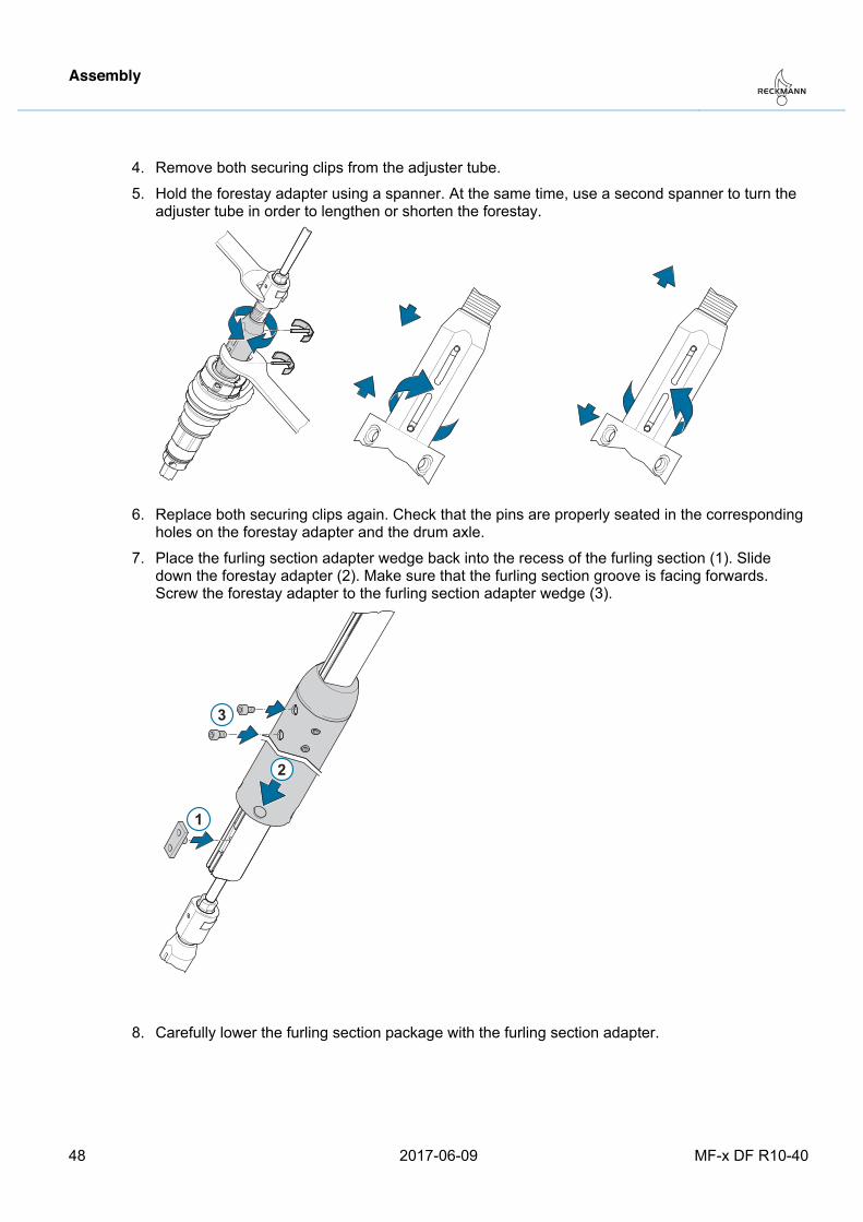
4. Remove both securing clips from the adjuster tube.
5. Hold the forestay adapter using a spanner. At the same time, use a second spanner to turn the adjuster tube in order to lengthen or shorten the forestay.
6. Replace both securing clips again. Check that the pins are properly seated in the corresponding holes on the forestay adapter and the drum axle.
7. Place the furling section adapter wedge back into the recess of the furling section (1). Slide down the forestay adapter (2). Make sure that the furling section groove is facing forwards. Screw the forestay adapter to the furling section adapter wedge (3).
2
3
1
8. Carefully lower the furling section package with the furling section adapter.
Pos: 61 /ZINDEL/Rollreffanlagen/Montage/MF-x DF/Profiladapter am Halsring montieren @ 1\mod_1488350748111_26.docx @ 18196 @ 2 @ 1
Assembly
MF-x DF R10-40 2017-06-09 49
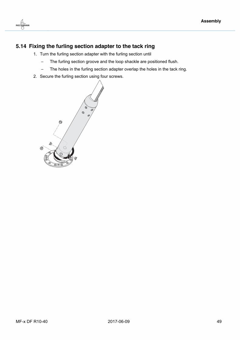
5.14 Fixing the furling section adapter to the tack ring 1. Turn the furling section adapter with the furling section until
− The furling section groove and the loop shackle are positioned flush.
− The holes in the furling section adapter overlap the holes in the tack ring.
2. Secure the furling section using four screws.
Pos: 62 /ZINDEL/Rollreffanlagen/Montage/Alu/R10 - R40/Fallenschlitten in endgültige Position schieben @ 1\mod_1444399543917_26.docx @ 16040 @ 2 @ 1
Assembly
50 2017-06-09 MF-x DF R10-40
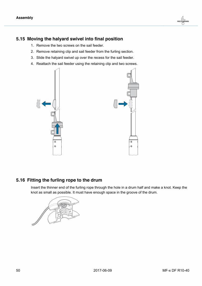
5.15 Moving the halyard swivel into final position 1. Remove the two screws on the sail feeder.
2. Remove retaining clip and sail feeder from the furling section.
3. Slide the halyard swivel up over the recess for the sail feeder.
4. Reattach the sail feeder using the retaining clip and two screws.
Pos: 63 /ZINDEL/Rollreffanlagen/Montage/MF/Reffleine an Trommel montieren_ohne Trommelmontage @ 1\mod_1488276501844_26.docx @ 18136 @ 2 @ 1
5.16 Fitting the furling rope to the drum Insert the thinner end of the furling rope through the hole in a drum half and make a knot. Keep the knot as small as possible. It must have enough space in the groove of the drum.
Pos: 64 /ZINDEL/Rollreffanlagen/Montage/MF-x DF/Trommel montieren MF-x DF @ 1\mod_1478529006091_26.docx @ 17671 @ 2 @ 1
Assembly
MF-x DF R10-40 2017-06-09 51
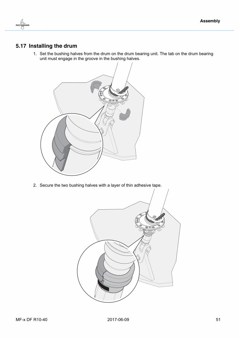
5.17 Installing the drum 1. Set the bushing halves from the drum on the drum bearing unit. The tab on the drum bearing
unit must engage in the groove in the bushing halves.
2. Secure the two bushing halves with a layer of thin adhesive tape.
Assembly
52 2017-06-09 MF-x DF R10-40
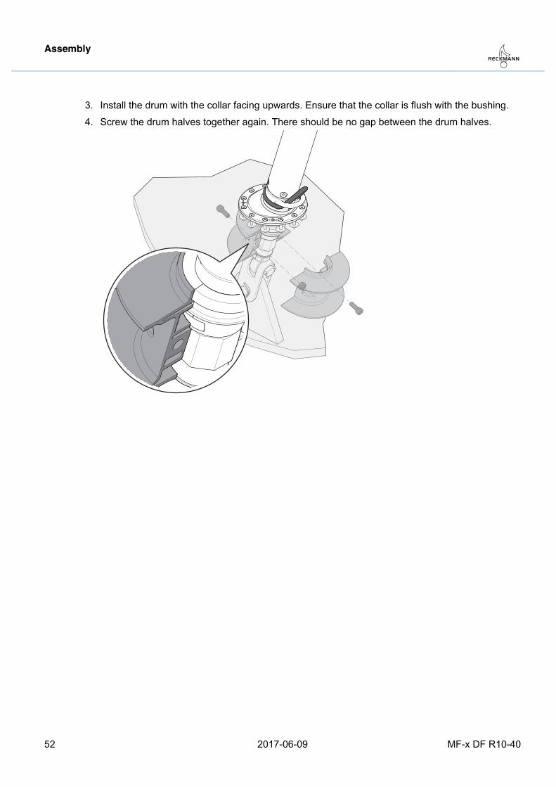
3. Install the drum with the collar facing upwards. Ensure that the collar is flush with the bushing.
4. Screw the drum halves together again. There should be no gap between the drum halves.
Pos: 65 /ZINDEL/Rollreffanlagen/Montage/MF-x DF/Schutzkorb montieren MF-x DF @ 1\mod_1478528797096_26.docx @ 17666 @ 2 @ 1
Assembly
MF-x DF R10-40 2017-06-09 53
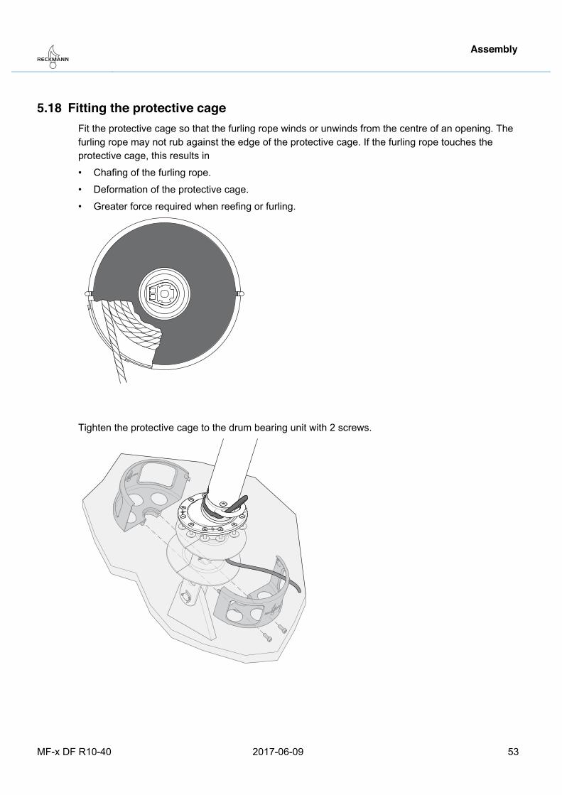
5.18 Fitting the protective cage Fit the protective cage so that the furling rope winds or unwinds from the centre of an opening. The furling rope may not rub against the edge of the protective cage. If the furling rope touches the protective cage, this results in
• Chafing of the furling rope.
• Deformation of the protective cage.
• Greater force required when reefing or furling.
Tighten the protective cage to the drum bearing unit with 2 screws.
Pos: 66 /ZINDEL/Rollreffanlagen/Bedienung/Drehrichtung @ 1\mod_1401198334606_26.docx @ 10142 @ 2 @ 1
Assembly
54 2017-06-09 MF-x DF R10-40
5.19 Direction of rotation
In principle, the furling system can roll up the sail clockwise or anticlockwise.
Select the direction of rotation to ensure that the side with the UV-resistant coating is facing outwards after the sail has been rolled up.
Pos: 67 /ZINDEL/Rollreffanlagen/Montage/MF-x DF/Reffleinen-Führung MF-x DF @ 1\mod_1479368750041_26.docx @ 17776 @ 2 @ 1
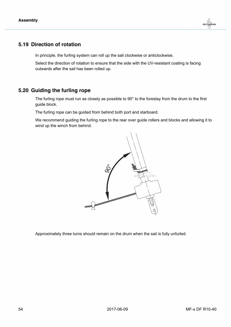
5.20 Guiding the furling rope The furling rope must run as closely as possible to 90° to the forestay from the drum to the first guide block.
The furling rope can be guided from behind both port and starboard.
We recommend guiding the furling rope to the rear over guide rollers and blocks and allowing it to wind up the winch from behind.
90°
Approximately three turns should remain on the drum when the sail is fully unfurled. Pos: 68 /ZINDEL/Rollreffanlagen/Bedienung/headline_Bedienung @ 1\mod_1400840094357_26.docx @ 10040 @ 1 @ 1
Operation
MF-x DF R10-40 2017-06-09 55
6 Operation Pos: 69 /ZINDEL/Rollreffanlagen/Bedienung/Kopfstander @ 1\mod_1400824020187_26.docx @ 10027 @ 2 @ 1
6.1 Wire pennant
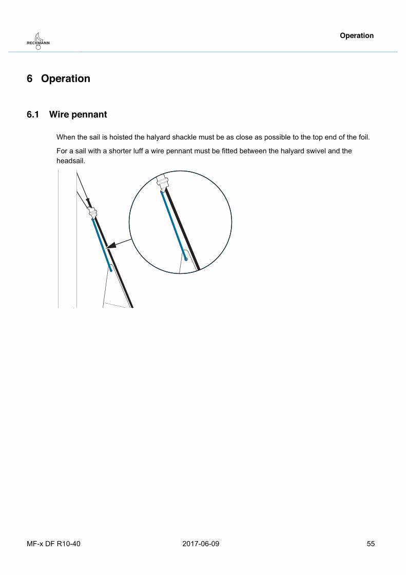
When the sail is hoisted the halyard shackle must be as close as possible to the top end of the foil.
For a sail with a shorter luff a wire pennant must be fitted between the halyard swivel and the headsail.
Pos: 70 /ZINDEL/Rollreffanlagen/Bedienung/Segel reffen und Segel ausrollen_MF @ 1\mod_1444911146804_26.docx @ 16076 @ 2333 @ 1
Operation
56 2017-06-09 MF-x DF R10-40
6.2 Furling and unfurling the sail
Warning Risk of injury − Prior to furling, make sure no one is in the area around the furling system. − The operator must have an adequate view of the furling system and the sail. If this is not
possible, a second person with an adequate view must maintain visual contact with the operator.
− Immediately stop the furling system if the sheet jams or the halyard starts wrapping.
Caution Risk of damage to furling system Jamming of the furling system will damage it. − Only reef or unfurl the sail with an eased sheet. - If the furling system becomes difficult to move, do not attempt to reef the sail with a great deal of
force. − Never furl counter to strong sheet tension. − The halyard must be slightly tensioned.
6.2.1 Furling In very light winds keep the sheet slightly tensioned so that the sail will furl tightly. In strong winds ease the sheet stepwise and reef the sail.
Stop reefing when the sheet has been rolled once or twice around the sail.
If the furling system becomes difficult to move, check the following:
− Is the halyard working correctly?
− Is the furling rope cleaning guided over blocks and deflection rollers?
− Is the sheet loose?
− Are any obstructions present?
6.2.2 Unfurling the sail Slightly pull the furling rope when unfurling the sail.
Keep the furling rope under slight tension when the sail is completely unfurled. The remaining winds on the drum may otherwise become loose.
Operation
MF-x DF R10-40 2017-06-09 57
6.2.3 Reefing A sheet lead positioned further in front is required when sailing with a reefed sail. For reefing proceed as follows:
1. Furl in the sail completely.
2. Adjust the new sheet lead position.
3. Unfurl the sail until the desired sail size is reached.
4. Secure the furling rope. Pos: 71 /ZINDEL/Rollreffanlagen/Bedienung/Profilvorstag_Regatta_MF-x DF @ 1\mod_1479129345515_26.docx @ 17736 @ 2 @ 1
Operation
58 2017-06-09 MF-x DF R10-40
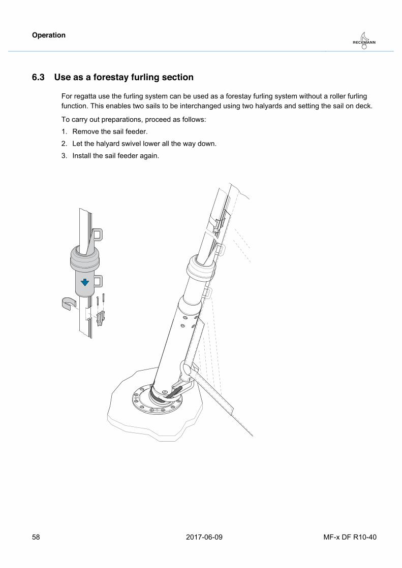
6.3 Use as a forestay furling section
For regatta use the furling system can be used as a forestay furling system without a roller furling function. This enables two sails to be interchanged using two halyards and setting the sail on deck.
To carry out preparations, proceed as follows:
1. Remove the sail feeder.
2. Let the halyard swivel lower all the way down.
3. Install the sail feeder again.
Pos: 72 /ZINDEL/Rollreffanlagen/Instandhaltung/Wartung/headline_Wartung @ 1\mod_1400760126985_26.docx @ 9954 @ 1 @ 1
Maintenance
MF-x DF R10-40 2017-06-09 59
7 Maintenance Pos: 73 /ZINDEL/Rollreffanlagen/Instandhaltung/Wartung/Wartung vor jeder Benutzung MF @ 1\mod_1444977789071_26.docx @ 16091 @ 2 @ 1
7.1 Prior to each use • Check ropes and lashings.
• Check the furling sections for external signs of damagePos: 74 /ZINDEL/Rollreffanlagen/Instandhaltung/Wartung/Wartung nach jeder Benutzung MF @ 1\mod_1444977803908_26.docx @ 16096 @ 2 @ 1
7.2 After each use • Rinse off all parts with fresh water.
Pos: 75 /ZINDEL/Rollreffanlagen/Instandhaltung/Wartung/Jährliche Wartung MF @ 1\mod_1444977815409_26.docx @ 16101 @ 2 @ 1
7.3 Annual maintenance The following tasks and checks must be carried out within the scope of annual maintenance:
• Remove all contaminants and salt deposits.
• Check the forestay for damage.
• Check all screws for a firm fit.
• Check the furling system for ease of movement.
• Check the halyard swivel for ease of movement.
• Replace loop shackle.
• Polish stainless steel parts.Pos: 76 /ZINDEL/Rollreffanlagen/Demontage/headline_Demontage @ 1\mod_1412165828515_26.docx @ 10487 @ 1 @ 1
Disassembly
60 2017-06-09 MF-x DF R10-40
8 Disassembly Pos: 77 /ZINDEL/Rollreffanlagen/Demontage/Warnung Demontage @ 1\mod_1435858963535_26.docx @ 15701 @ @ 1
Warning Falling and vibrating components Parts that are improperly secured may cause serious injury. − The furling system may only be disassembled by qualified staff, such as a mast builder. − Wear protective clothing, including safety helmet and work boots. − Prior to disassembly, use appropriate means to secure any parts that may fall or vibrate.
Warning Risk of crushing and shearing − Never stick your finger into a threaded hole.
Pos: 78 /ZINDEL/Rollreffanlagen/Demontage/Demontage MF-x DF @ 1\mod_1478530741641_26.docx @ 17686 @ @ 1
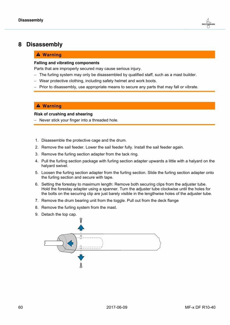
1. Disassemble the protective cage and the drum.
2. Remove the sail feeder. Lower the sail feeder fully. Install the sail feeder again.
3. Remove the furling section adapter from the tack ring.
4. Pull the furling section package with furling section adapter upwards a little with a halyard on the halyard swivel.
5. Loosen the furling section adapter from the furling section. Slide the furling section adapter onto the furling section and secure with tape.
6. Setting the forestay to maximum length: Remove both securing clips from the adjuster tube. Hold the forestay adapter using a spanner. Turn the adjuster tube clockwise until the holes for the bolts on the securing clip are just barely visible in the lengthwise holes of the adjuster tube.
7. Remove the drum bearing unit from the toggle. Pull out from the deck flange
8. Remove the furling system from the mast.
9. Detach the top cap.
Disassembly
MF-x DF R10-40 2017-06-09 61
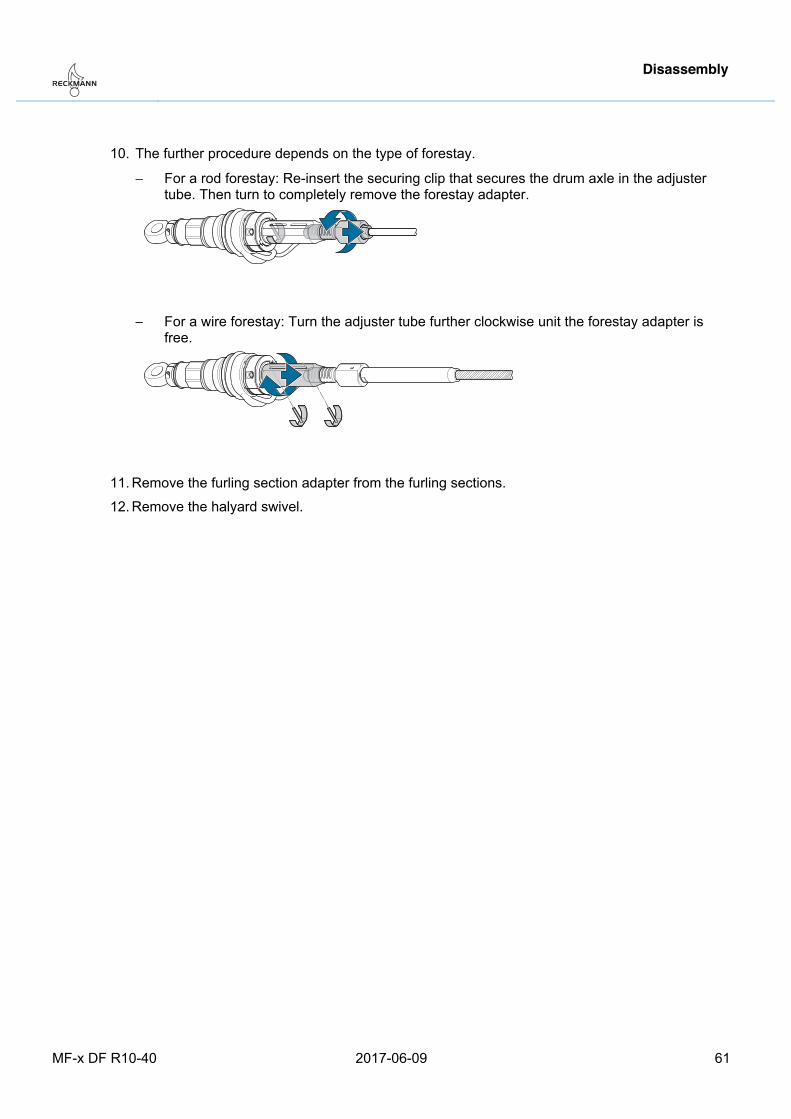
10. The further procedure depends on the type of forestay.
− For a rod forestay: Re-insert the securing clip that secures the drum axle in the adjuster tube. Then turn to completely remove the forestay adapter.
− For a wire forestay: Turn the adjuster tube further clockwise unit the forestay adapter is free.
11. Remove the furling section adapter from the furling sections.
12. Remove the halyard swivel.
Pos: 79 /ZINDEL/Rollreffanlagen/Transport und Lagerung/Lagerung MF @ 1\mod_1444984352794_26.docx @ 16110 @ 1 @ 1

Storage
62 2017-06-09 MF-x DF R10-40
9 Storage
Caution Risk of destruction of furling system by freezing water In regions in which there is a danger of frost disassemble the furling system prior to storing for the winter.
Store the furling system parts in a dry room. Pos: 80 /ZINDEL/Rollreffanlagen/Entsorgung MF @ 1\mod_1444985301016_26.docx @ 16115 @ 1 @ 1
Disposal
MF-x DF R10-40 2017-06-09 63
10 Disposal
Caution Risk of damage to the environment The halyard swivel and drum bearing unit contain lubricants that may cause serious environmental harm. Dispose of the furling system parts in an environmentally friendly manner in accordance with local requirements.
Sort the furling system parts and dispose of them in accordance with the applicable local requirements.
Pos: 81 /ZINDEL/Rollreffanlagen/headline_Technische Daten @ 1\mod_1416391342849_26.docx @ 11210 @ 1 @ 1
Technical data
64 2017-06-09 MF-x DF R10-40
11 Technical data Pos: 82 /ZINDEL/Rollreffanlagen/Maße_MF-x DF @ 1\mod_1479213941375_26.docx @ 17751 @ 2 @ 1
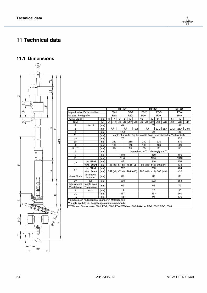
11.1 Dimensions
ZSL
*LH
SL*
TLLS
LFB D
FS
T
ADF
GE
Ymax
. tHD
DDg
d
10°
Pos: 83 /ZINDEL/Rollreffanlagen/Technische Daten Querschnitte Alu_MF R10-R40 @ 1\mod_1479213585005_26.docx @ 17746 @ 2 @ 1
Technical data
MF-x DF R10-40 2017-06-09 65
11.2 Furling section cross sections
AB
O G
Furling section type
Groove G [mm]
O [mm]
A [mm]
B [mm]
R10 Double 6.4 2.3 32.4 24.1
R20 Double 6.4 2.3 35.8 28.8
R30 Double 7.5 3.0 45.5 36.1
R40 Double 7.5 3.0 49.1 38.7
Pos: 84 /ZINDEL/_Steuermodule/Texte Template @ 1\mod_1467358922020_26.docx @ 17211 @ @ 1
Revised Table of contents Index
Germany Notes Dimensions
Calculating the furling section length and the offcut measurement === Ende der Liste für Textmarke Inhalt ===
Index
66 2017-06-09 MF-x DF R10-40
12 Index Adjuster tube 31 Adjusting the furling section length 13 Assembly 13 Bushing stopper 5, 39 Calculation
of the furling section length and the offcut measurement 13
of the hole in the deck 24 Caution 8 Cold-headed rod end (rod head) 15, 19 Cover ring 4 Deck flange 4, 23
screwing on 36 support 34 underpinning 34
Design 11 Direction of rotation 54 Disassembly 60 Display conventions 8 Disposal 63 Drum 4, 11 Drum bearing unit 4
connecting to rod forestay 28 connecting to wire forestay 29 connecting with forestay 27 setting the length 25
Drum bushing 4 Drum height See drum bearing unit: setting the
length Feeder section 5, 39 Forestay 4, 11
connecting with drum bearing unit 27 Forestay furling section 9, 58 Forestay length 31 Function 12 Furling 56 Furling section adapter 4, 11 Furling section adapter wedge 6, 44, 47, 48 Furling section connector 6 Furling section cross section 65 Furling section reinforcement 5, 40 Gap dimension 33
Halyard lead 9 Halyard swivel 4, 11 Hole
calculation 24 Intended use 9 Length
of the forestay 31 Maintenance 59 Mast head 45 Mast toggle 30, 45 Notice 8 Offcut measurement C 13 Overview 11 Protective cage 4, 11 Rod forestay 4
connecting to drum bearing unit 28 Rod nose 4 Safety 9 Sail feeder 6, 11 Sail UV protection 54 Shortening
top furling section 13 top spacer 14
Storage 62 Swage terminal 4, 23 Swageless stud terminal 23 Technical data 64 Threaded plate 6, 38, 39, 40 Toggle 4, 11, 25 Top bushing 11, 14 Top cap 44 Top furling section 5, 13, 38 Top spacer 5, 14 Top terminal 4, 11
rod terminal 15 swage terminal 23 swageless stud terminal 23 wire terminal 23
Warning 8 Wire forestay 4
connecting to drum bearing unit 29 Wire pennant 55