NSC ECDIS OPERATOR MANUAL - raytheon-anschuetz.com · Control Previous/ Next Zoom In/ Out Center On...
445
Raytheon Anschütz GmbH Postfach 1166 D -- 24100Kiel Germany Tel +49--4 31--30 19--0 Fax +49--4 31--30 19--501 Email [email protected] www.raytheon--anschuetz.de 3655.DOC012 Edition: 28.JUL.2014 NSC ECDIS OPERATOR MANUAL
Transcript of NSC ECDIS OPERATOR MANUAL - raytheon-anschuetz.com · Control Previous/ Next Zoom In/ Out Center On...
Raytheon Anschütz GmbHPostfach 1166D -- 24100 KielGermanyTel +49--4 31--30 19--0Fax +49--4 31--30 19--501Email [email protected]
3655.DOC012 Edition: 28.JUL.2014
NSC ECDIS
OPERATOR MANUAL

Weitergabe sowie Vervielfältigung dieser Unterlage, Verwertung undMitteilung ihres Inhaltes nicht gestattet, soweit nicht ausdrücklichzugestanden. Zuwiderhandlungen verpflichten zu Schadenersatz.
Copying of this document, and giving it to others and the use orcommunication of the contents thereof, are forbidden without expressauthority. Offenders are liable to the payment of damages.
Toute communication ou reproduction de ce document, touteexploitation ou communication de son contenu sont interdites, saufautorisation expresse. Tout manquement à cette règle est illicite etexpose son auteur au versement de dommages et intérêts.
Sin nuestra expresa autorización, queda terminantemente prohibida lareproducción total o parcial de este documento, así como su usoindebido y/o su exhibición o comunicación a terceros. De los infractoresse exigirá el correspondiente resarcimiento de daños y perjuicios.
SH
OR
TO
PE
RA
TIO
NR
ayth
eon
Ans
chüt
zG
mbH
Ger
man
y
RN
SC
EC
DIS
3655
DO
C02
01E
ditio
n:12
.JU
LY.2
012
DIS
PL
AY
ME
NU
(cha
pter
6)
Z
oom
Inor
Zoo
mou
t
ch
ange
sth
esc
ale
ofth
edi
spla
y(d
efau
lt,la
rges
t,
spec
ified
and
cent
er)
sa
ves,
open
san
dde
lete
sar
eavi
ews
pre
--def
ined
byth
e
user
ke
epin
gyo
ursh
ipin
the
disp
lay
area
(shi
pce
nter
)
ow
nsh
ipsy
mbo
lwill
bedi
spla
yed
onsc
ale
as
silh
ouet
te
ch
ange
sdi
spla
yco
lors
to
olba
rO
nor
Off
S
tatu
sB
arO
nor
Off.
Info
rmat
ion
Pan
elO
nor
Off
and
pane
lsel
ectio
ne.
g.N
AV
orT
RA
CK
PL
OT
LA
YE
RC
OM
MA
ND
(cha
pter
10)
dr
awin
gto
ol
m
erge
stw
oor
mor
eob
ject
grou
ps
E
xpor
t/Im
port
obje
ctgr
oups
RO
UT
ES
ME
NU
(cha
pter
8)
ro
ute
info
rmat
ion
abou
tsym
bols
,ser
ver
orcl
ient
right
s
cr
eate
ored
ita
prim
ary
orse
cond
ary
rout
e
op
ena
save
dpr
imar
yor
seco
ndar
yro
ute
fo
rau
tom
atic
rout
epl
anni
ng/p
orti
nfor
mat
ion
to
ggle
prim
ary
and
seco
ndar
yro
ute
na
mes
and
save
sa
rout
eto
the
rout
elis
t
ce
nter
the
disp
lay
onth
eac
tive
way
poin
toft
heop
enro
ute
sh
ows
the
way
poin
tlis
toft
hero
ute
cl
ears
the
open
rout
efr
omth
edi
spla
y
de
lete
ssa
ved
rout
e
se
nds
and
disp
lays
rout
ein
form
atio
nto
rada
r
st
art/s
top
rout
em
onito
ring
ortr
ack
cont
rol
ca
lcul
ates
and
show
sD
ista
nce
--To
--Run
sym
bolp
osi--
tions
onth
ero
ute.
Sho
ws
time
for
plan
ned
posi
tion
al
low
sth
eus
erto
writ
ea
chec
klis
t(le
avin
gth
eha
rbor
,
chan
ging
aro
ute
ch
ange
sW
OP
alar
mse
tting
s
ch
ecks
aro
ute
pass
ing
are
stric
ted
area
ro
ute
serv
errig
hts
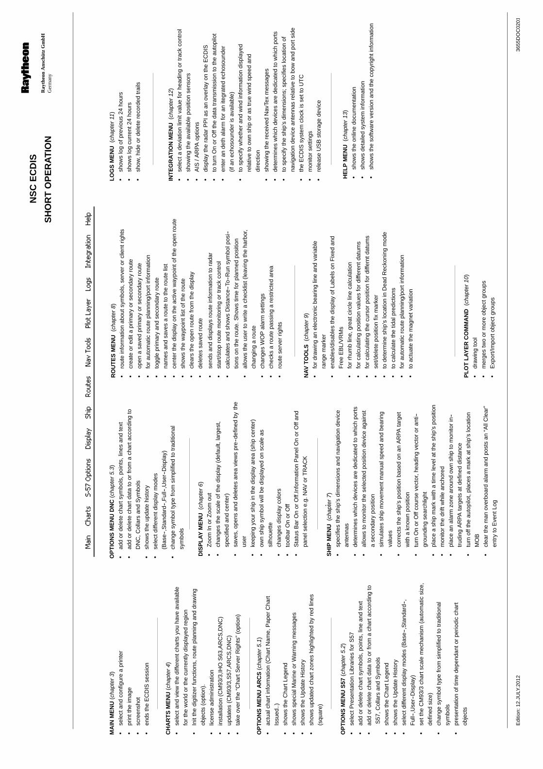
MA
INM
EN
U(c
hapt
er3)
se
lect
and
conf
igur
ea
prin
ter
pr
intt
heim
age
sc
reen
shot
en
dsth
eE
CD
ISse
ssio
n
CH
AR
TS
ME
NU
(cha
pter
4)
se
lect
and
view
the
diffe
rent
char
tsyo
uha
veav
aila
ble
for
the
wor
ldor
the
curr
ently
disp
laye
dre
gion
In
itth
edi
gitiz
erfu
nctio
ns,r
oute
plan
ning
and
draw
ing
obje
cts
(opt
ion)
.
lic
ense
adm
inis
trat
ion
in
stal
latio
n(C
M93
/3,IH
OS
63,A
RC
S,D
NC
)
up
date
s(C
M93
/3,S
57,A
RC
S,D
NC
)
ta
keov
erth
e“C
hart
Ser
ver
Rig
hts”
(opt
ion)
OP
TIO
NS
ME
NU
AR
CS
(cha
pter
5.1)
ac
tual
char
tinf
orm
atio
n(C
hart
Nam
e,P
aper
Cha
rt
Issu
ed..)
sh
ows
the
Cha
rtLe
gend
sh
ows
spec
ialM
arin
eor
War
ning
mes
sage
s
sh
ows
the
Upd
ate
His
tory
sh
ows
upda
ted
char
tzon
eshi
ghlig
hted
byre
dlin
es
(squ
are)
OP
TIO
NS
ME
NU
S57
(cha
pter
5.2)
se
lect
Pre
sent
atio
nLi
brar
ies
for
S57
ad
dor
dele
tech
arts
ymbo
ls,p
oint
s,lin
ean
dte
xt
ad
dor
dele
tech
artd
ata
toor
from
ach
arta
ccor
ding
to
S57
,Col
lars
and
Sym
bols
sh
ows
the
Cha
rtLe
gend
sh
ows
the
Upd
ate
His
tory
se
lect
diffe
rent
disp
lay
mod
es(B
ase
--,S
tand
ard
--,
Ful
l--,U
ser--
Dis
play
)
se
tthe
CM
93/3
char
tsca
lem
echa
nism
(aut
omat
icsi
ze,
defin
edsi
ze)
ch
ange
sym
bolt
ype
from
sim
plifi
edto
trad
ition
al
sym
bols
pr
esen
tatio
nof
time
depe
ndan
tor
perio
dic
char
t
obje
cts
OP
TIO
NS
ME
NU
DN
C(c
hapt
er5.
3)
ad
dor
dele
tech
arts
ymbo
ls,p
oint
s,lin
esan
dte
xt
ad
dor
dele
tech
artd
ata
toor
from
ach
arta
ccor
ding
to
DN
C,C
olla
rsan
dS
ymbo
ls
sh
ows
the
upda
tehi
stor
y
se
lect
diffe
rent
disp
lay
mod
es
(Bas
e--,
Sta
ndar
d--,
Ful
l--,U
ser--
Dis
play
)
ch
ange
sym
bolt
ype
from
sim
plifi
edto
trad
ition
al
sym
bols
SH
IPM
EN
U(c
hapt
er7)
sp
ecifi
esth
esh
ip’s
dim
ensi
ons
and
navi
gatio
nde
vice
ante
nnas
de
term
ines
whi
chde
vice
sar
ede
dica
ted
tow
hich
port
s
al
low
sto
mon
itor
the
sele
cted
posi
tion
devi
ceag
ains
t
ase
cond
ary
posi
tion
si
mul
ates
ship
mov
emen
tman
uals
peed
and
bear
ing
valu
es
co
rrec
tsth
esh
ip’s
posi
tion
base
don
anA
RP
Ata
rget
with
akn
own
posi
tion
tu
rnO
nor
Off
cour
seve
ctor
,hea
ding
vect
oror
anti-
-
grou
ndin
gse
arch
light
pl
ace
ash
ipm
ark
with
atim
ele
vela
tthe
ship
’spo
sitio
n
m
onito
rth
edr
iftw
hile
anch
ored
pl
ace
anal
arm
zone
arou
ndow
nsh
ipto
mon
itor
in--
trud
ing
AR
PA
targ
ets
atde
fined
dist
ance
tu
rnof
fthe
auto
pilo
t,pl
aces
am
ark
atsh
ip’s
loca
tion
MO
B
cl
ear
the
man
over
boar
dal
arm
and
post
san
“All
Cle
ar”
entr
yto
Eve
ntLo
g
NA
VTO
OL
S(c
hapt
er9)
fo
rdr
awin
gan
elec
tron
icbe
arin
glin
ean
dva
riabl
e
rang
em
arke
r
en
able
s/di
sabl
esth
edi
spla
yof
Labe
lson
Fix
edan
d
Fre
eE
BL/
VR
Ms
fo
rrh
umb
line,
grea
tcirc
lelin
eca
lcul
atio
n
fo
rca
lcul
atin
gpo
sitio
nva
lues
for
diffe
rent
datu
ms
fo
rca
lcul
atin
gth
ecu
rsor
posi
tion
for
diffe
rntd
atum
s
se
t/del
ete
posi
tion
fixm
arke
r
to
dete
rmin
esh
ip’s
loca
tion
inD
ead
Rec
koni
ngm
ode
to
calc
ulat
eth
etid
alpr
edic
tions
fo
rau
tom
atic
rout
epl
anni
ng/p
orti
nfor
mat
ion
to
actu
ate
the
mag
netv
aria
tion
LO
GS
ME
NU
(cha
pter
11)
sh
ows
log
ofpr
evio
us24
hour
s
sh
ows
log
curr
ent2
4ho
urs
sh
ow,h
ide
orde
lete
reco
rded
trai
ls
INT
EG
RA
TIO
NM
EN
U(c
hapt
er12
)
se
lect
ade
viat
ion
limit
valu
efo
rhe
adin
gor
trac
kco
ntro
l
sh
owin
gth
eav
aila
ble
posi
tion
sens
ors
A
IS/A
RP
Aop
tions
di
spla
yth
era
dar
PP
Ias
anov
erla
yon
the
EC
DIS
to
turn
On
orO
ffth
eda
tatr
ansm
issi
onto
the
auto
pilo
t
en
ter
ande
thal
arm
for
anite
grat
edec
hoso
unde
r
(ifan
echo
soun
der
isav
aila
ble)
to
spec
ifyw
heth
eran
dw
ind
info
rmat
ion
disp
laye
d
rela
tive
toow
nsh
ipor
astr
uew
ind
spee
dan
d
dire
ctio
n
sh
owin
gth
ere
ceiv
edN
avTe
xm
essa
ges
de
term
ines
whi
chde
vice
sar
ede
dica
ted
tow
hich
port
s
to
spec
ifyth
esh
ip’s
dim
ensi
ons;
spec
ifies
loca
tion
of
navi
gatio
nde
vice
ante
nnas
rela
tive
tobo
wan
dpo
rtsi
de
th
eE
CD
ISsy
stem
cloc
kis
sett
oU
TC
m
onito
rse
tting
s
re
leas
eU
SB
stor
age
devi
ce
HE
LP
ME
NU
(cha
pter
13)
sh
ows
the
onlin
edo
cum
enta
tion
sh
ows
deta
iled
syst
emin
form
atio
n
sh
ows
the
softw
are
vers
ion
and
the
copy
right
info
rmat
ion
SH
OR
TO
PE
RA
TIO
NR
ayth
eon
Ans
chüt
zG
mbH
Ger
man
y
RN
SC
EC
DIS
3655
DO
C02
01E
ditio
n:15
.JA
N.2
013
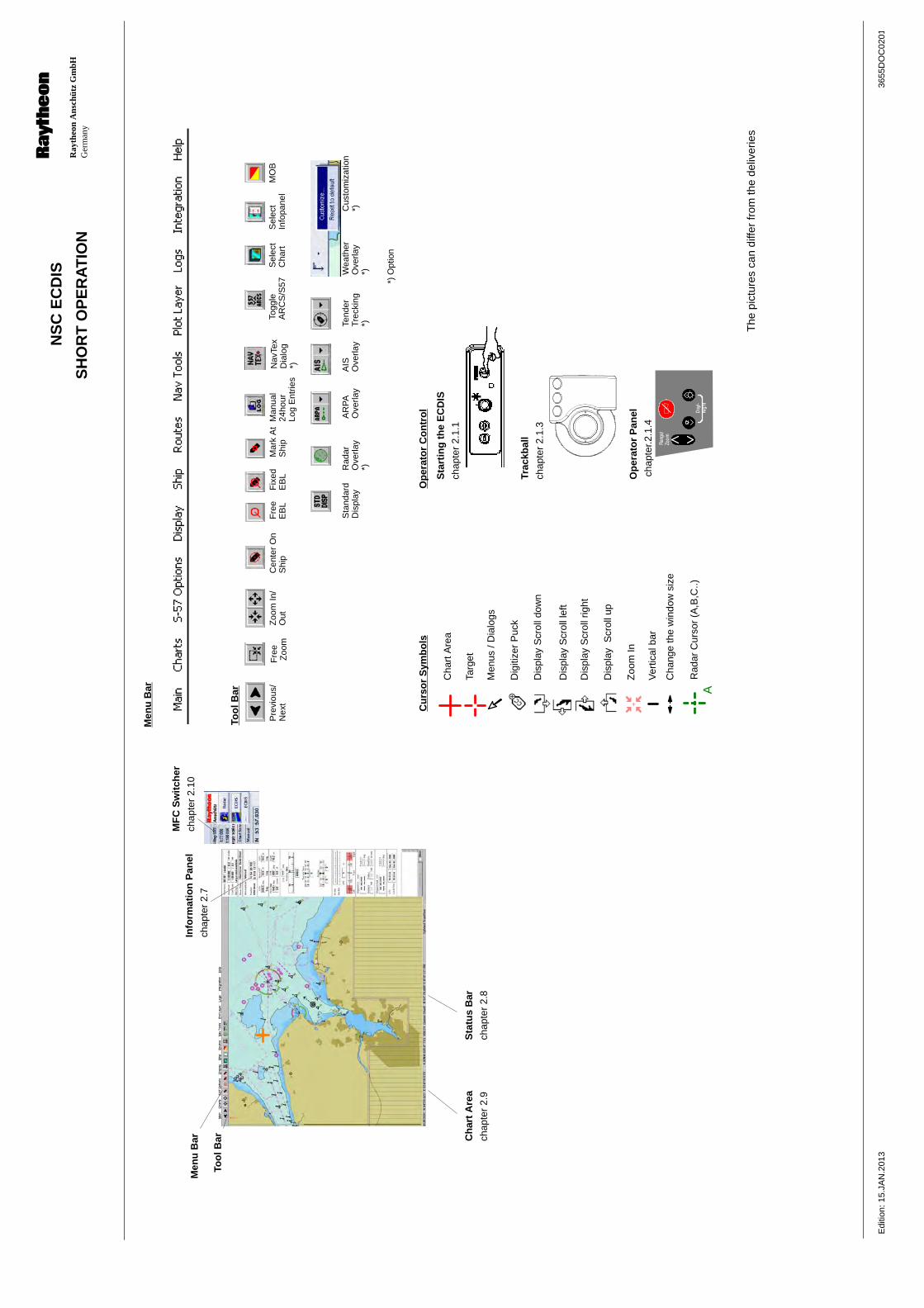
Too
lBar
Info
rmat
ion
Pan
el
chap
ter
2.7
Ch
art
Are
a
chap
ter
2.9
Sta
tus
Bar
chap
ter
2.8
Trac
kbal
l
chap
ter
2.1.
3
Op
erat
or
Pan
el
chap
ter.2
.1.4
Sta
rtin
gth
eE
CD
IS
chap
ter
2.1.
1C
hart
Are
a
Targ
et
Dig
itize
rP
uck
Dis
play
Scr
olld
own
Dis
play
Scr
olll
eft
Dis
play
Scr
ollr
ight
Dis
play
Scr
ollu
p
Zoo
mIn
Men
us/D
ialo
gs
Ver
tical
bar
Cha
nge
the
win
dow
size
Cu
rso
rS
ymb
ols
Op
erat
or
Co
ntr
ol
Pre
viou
s/N
ext
Zoo
mIn
/O
utC
ente
rO
nS
hip
Fre
eE
BL
Fix
edE
BL
Mar
kA
tS
hip
Sel
ect
Cha
rtM
OB
Sta
ndar
dD
ispl
ayR
adar
Ove
rlay
*)
*)O
ptio
n
Men
uB
ar
Rad
arC
urso
r(A
,B,C
..)A
AR
PA
Ove
rlay
AIS
Ove
rlay
Sel
ect
Info
pane
l
The
pict
ures
can
diffe
rfr
omth
ede
liver
ies
MF
CS
wit
cher
chap
ter
2.10
Fre
eZ
oom
Tend
erTr
ecki
ng*)
Man
ual
24ho
urLo
gE
ntrie
s
Togg
leA
RC
S/S
57
Too
lBar
Men
uB
ar
Nav
Tex
Dia
log
*)
Wea
ther
Ove
rlay
*)
Cus
tom
izat
ion
*)
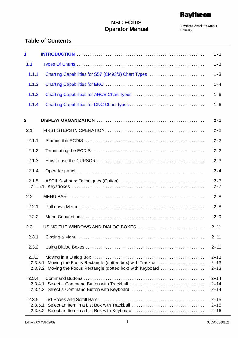
Operator Manual
Table of Contents
Raytheon Anschütz GmbHGermany
RNSC ECDIS
I 3655OC020102Edition: 03.MAR.2009
1 INTRODUCTION 1--1. . . . . . . . . . . . . . . . . . . . . . . . . . . . . . . . . . . . . . . . . . . . . . . . . . . . . . . . . .
1.1 Types Of Charts 1--3. . . . . . . . . . . . . . . . . . . . . . . . . . . . . . . . . . . . . . . . . . . . . . . . . . . . . . . . . .
1.1.1 Charting Capabilities for S57 (CM93/3) Chart Types 1--3. . . . . . . . . . . . . . . . . . . . . . . . .
1.1.2 Charting Capabilities for ENC 1--4. . . . . . . . . . . . . . . . . . . . . . . . . . . . . . . . . . . . . . . . . . . . .
1.1.3 Charting Capabilities for ARCS Chart Types 1--6. . . . . . . . . . . . . . . . . . . . . . . . . . . . . . . .
1.1.4 Charting Capabilities for DNC Chart Types 1--6. . . . . . . . . . . . . . . . . . . . . . . . . . . . . . . . . .
2 DISPLAY ORGANIZATION 2--1. . . . . . . . . . . . . . . . . . . . . . . . . . . . . . . . . . . . . . . . . . . . . . . . .
2.1 FIRST STEPS IN OPERATION 2--2. . . . . . . . . . . . . . . . . . . . . . . . . . . . . . . . . . . . . . . . . . . .
2.1.1 Starting the ECDIS 2--2. . . . . . . . . . . . . . . . . . . . . . . . . . . . . . . . . . . . . . . . . . . . . . . . . . . . . .
2.1.2 Terminating the ECDIS 2--2. . . . . . . . . . . . . . . . . . . . . . . . . . . . . . . . . . . . . . . . . . . . . . . . . . .
2.1.3 How to use the CURSOR 2--3. . . . . . . . . . . . . . . . . . . . . . . . . . . . . . . . . . . . . . . . . . . . . . . . .
2.1.4 Operator panel 2--4. . . . . . . . . . . . . . . . . . . . . . . . . . . . . . . . . . . . . . . . . . . . . . . . . . . . . . . . . .
2.1.5 ASCII Keyboard Techniques (Option) 2--7. . . . . . . . . . . . . . . . . . . . . . . . . . . . . . . . . . . . . .2.1.5.1 Keystrokes 2--7. . . . . . . . . . . . . . . . . . . . . . . . . . . . . . . . . . . . . . . . . . . . . . . . . . . . . . . . . . . .
2.2 MENU BAR 2--8. . . . . . . . . . . . . . . . . . . . . . . . . . . . . . . . . . . . . . . . . . . . . . . . . . . . . . . . . . . . . .
2.2.1 Pull down Menu 2--8. . . . . . . . . . . . . . . . . . . . . . . . . . . . . . . . . . . . . . . . . . . . . . . . . . . . . . . . .
2.2.2 Menu Conventions 2--9. . . . . . . . . . . . . . . . . . . . . . . . . . . . . . . . . . . . . . . . . . . . . . . . . . . . . .
2.3 USING THE WINDOWS AND DIALOG BOXES 2--11. . . . . . . . . . . . . . . . . . . . . . . . . . . . . .
2.3.1 Closing a Menu 2--11. . . . . . . . . . . . . . . . . . . . . . . . . . . . . . . . . . . . . . . . . . . . . . . . . . . . . . . . .
2.3.2 Using Dialog Boxes 2--11. . . . . . . . . . . . . . . . . . . . . . . . . . . . . . . . . . . . . . . . . . . . . . . . . . . . . .
2.3.3 Moving in a Dialog Box 2--13. . . . . . . . . . . . . . . . . . . . . . . . . . . . . . . . . . . . . . . . . . . . . . . . . . .2.3.3.1 Moving the Focus Rectangle (dotted box) with Trackball 2--13. . . . . . . . . . . . . . . . . . . . .2.3.3.2 Moving the Focus Rectangle (dotted box) with Keyboard 2--13. . . . . . . . . . . . . . . . . . . .
2.3.4 Command Buttons 2--14. . . . . . . . . . . . . . . . . . . . . . . . . . . . . . . . . . . . . . . . . . . . . . . . . . . . . . .2.3.4.1 Select a Command Button with Trackball 2--14. . . . . . . . . . . . . . . . . . . . . . . . . . . . . . . . . .2.3.4.2 Select a Command Button with Keyboard 2--14. . . . . . . . . . . . . . . . . . . . . . . . . . . . . . . . .
2.3.5 List Boxes and Scroll Bars 2--15. . . . . . . . . . . . . . . . . . . . . . . . . . . . . . . . . . . . . . . . . . . . . . . .2.3.5.1 Select an Item in a List Box with Trackball 2--15. . . . . . . . . . . . . . . . . . . . . . . . . . . . . . . . .2.3.5.2 Select an Item in a List Box with Keyboard 2--16. . . . . . . . . . . . . . . . . . . . . . . . . . . . . . . .
Operator Manual
Table of Contents
II3655DOC020102 Edition: 03.MAR.2009
2.3.6 Text Boxes 2--17. . . . . . . . . . . . . . . . . . . . . . . . . . . . . . . . . . . . . . . . . . . . . . . . . . . . . . . . . . . . .2.3.6.1 Entering Information in a Text Box with Trackball 2--17. . . . . . . . . . . . . . . . . . . . . . . . . . .2.3.6.2 Entering Information in a Text Box with Keyboard 2--18. . . . . . . . . . . . . . . . . . . . . . . . . . .
2.3.7 Using Option Buttons 2--19. . . . . . . . . . . . . . . . . . . . . . . . . . . . . . . . . . . . . . . . . . . . . . . . . . . .2.3.7.1 Select or Clear an Option Button with Trackball 2--19. . . . . . . . . . . . . . . . . . . . . . . . . . . .2.3.7.2 Select or Clear an Option Button with Keyboard 2--19. . . . . . . . . . . . . . . . . . . . . . . . . . . .
2.3.8 Using Check Boxes 2--20. . . . . . . . . . . . . . . . . . . . . . . . . . . . . . . . . . . . . . . . . . . . . . . . . . . . . .2.3.8.1 Selecting/Clearing a Check Box with Trackball 2--20. . . . . . . . . . . . . . . . . . . . . . . . . . . . .2.3.8.2 Selecting/Clearing a Check Box with Keyboard 2--20. . . . . . . . . . . . . . . . . . . . . . . . . . . . .
2.3.9 Latitude/ Longitude Boxes 2--21. . . . . . . . . . . . . . . . . . . . . . . . . . . . . . . . . . . . . . . . . . . . . . . .2.3.9.1 Specify a Coordinate Using the Trackball 2--21. . . . . . . . . . . . . . . . . . . . . . . . . . . . . . . . . .2.3.9.2 Specify a Coordinate Using the Keyboard 2--21. . . . . . . . . . . . . . . . . . . . . . . . . . . . . . . . .
2.3.10 Plural Selection 2--22. . . . . . . . . . . . . . . . . . . . . . . . . . . . . . . . . . . . . . . . . . . . . . . . . . . . . . . . .2.3.10.1 Activate the Chart or Object Info window by clicking on middle button 2--23. . . . . . . . .
2.4 TOOL BAR 2--26. . . . . . . . . . . . . . . . . . . . . . . . . . . . . . . . . . . . . . . . . . . . . . . . . . . . . . . . . . . . . .
2.4.1 Pull down Menu 2--28. . . . . . . . . . . . . . . . . . . . . . . . . . . . . . . . . . . . . . . . . . . . . . . . . . . . . . . . .
2.4.2 Customization 2--28. . . . . . . . . . . . . . . . . . . . . . . . . . . . . . . . . . . . . . . . . . . . . . . . . . . . . . . . . . .
2.5 CURSOR SYMBOLS 2--32. . . . . . . . . . . . . . . . . . . . . . . . . . . . . . . . . . . . . . . . . . . . . . . . . . . . .
2.6 SHIP SYMBOLS IN THE CHART AREA 2--33. . . . . . . . . . . . . . . . . . . . . . . . . . . . . . . . . . . . .2.6.1 Circle 2--33. . . . . . . . . . . . . . . . . . . . . . . . . . . . . . . . . . . . . . . . . . . . . . . . . . . . . . . . . . . . . . . . .
2.6.2 Rectangular Ship 2--33. . . . . . . . . . . . . . . . . . . . . . . . . . . . . . . . . . . . . . . . . . . . . . . . . . . . . . . .
2.7 INFORMATION PANEL 2--34. . . . . . . . . . . . . . . . . . . . . . . . . . . . . . . . . . . . . . . . . . . . . . . . . . .2.7.1 Operational Steering Modes of ECDIS 2--36. . . . . . . . . . . . . . . . . . . . . . . . . . . . . . . . . . . .2.7.1.1 Alarm Messages 2--39. . . . . . . . . . . . . . . . . . . . . . . . . . . . . . . . . . . . . . . . . . . . . . . . . . . . . . .
2.8 STATUS BAR CURSOR/CHART CENTER 2--40. . . . . . . . . . . . . . . . . . . . . . . . . . . . . . . . . . .
2.9 CHART AREA 2--41. . . . . . . . . . . . . . . . . . . . . . . . . . . . . . . . . . . . . . . . . . . . . . . . . . . . . . . . . . .2.9.1 Chart Boundaries 2--41. . . . . . . . . . . . . . . . . . . . . . . . . . . . . . . . . . . . . . . . . . . . . . . . . . . . . . .2.9.1.1 S57/3 (C--MAP93/3), IHO S--63 2--42. . . . . . . . . . . . . . . . . . . . . . . . . . . . . . . . . . . . . . . . . .2.9.1.2 Track Plotter 2--43. . . . . . . . . . . . . . . . . . . . . . . . . . . . . . . . . . . . . . . . . . . . . . . . . . . . . . . . . . .
2.10 MFC Switcher (Option) 2--44. . . . . . . . . . . . . . . . . . . . . . . . . . . . . . . . . . . . . . . . . . . . . . . . . . . .
2.10.1 Using the MFC Switcher 2--44. . . . . . . . . . . . . . . . . . . . . . . . . . . . . . . . . . . . . . . . . . . . . . . . . .2.10.1.1 Changing Display Colors 2--44. . . . . . . . . . . . . . . . . . . . . . . . . . . . . . . . . . . . . . . . . . . . . . . .
2.11 Conning Display Compact (Option) 2--45. . . . . . . . . . . . . . . . . . . . . . . . . . . . . . . . . . . . . . . . .
Operator Manual
Table of Contents
Raytheon Anschütz GmbHGermany
RNSC ECDIS
III 3655OC020102Edition: 26.JUL.2010
3 MAIN MENU 3--1. . . . . . . . . . . . . . . . . . . . . . . . . . . . . . . . . . . . . . . . . . . . . . . . . . . . . . . . . . . . . .
3.1 MAIN MENU COMMANDS 3--1. . . . . . . . . . . . . . . . . . . . . . . . . . . . . . . . . . . . . . . . . . . . . . . .
3.1.1 Printer Setup 3--2. . . . . . . . . . . . . . . . . . . . . . . . . . . . . . . . . . . . . . . . . . . . . . . . . . . . . . . . . . .
3.1.3 Screenshot 3--3. . . . . . . . . . . . . . . . . . . . . . . . . . . . . . . . . . . . . . . . . . . . . . . . . . . . . . . . . . . . .
3.1.4 Exit 3--5. . . . . . . . . . . . . . . . . . . . . . . . . . . . . . . . . . . . . . . . . . . . . . . . . . . . . . . . . . . . . . . . . . . .
4 CHART MENU 4--1. . . . . . . . . . . . . . . . . . . . . . . . . . . . . . . . . . . . . . . . . . . . . . . . . . . . . . . . . . . .
4.1 CHART MENU COMMANDS 4--1. . . . . . . . . . . . . . . . . . . . . . . . . . . . . . . . . . . . . . . . . . . . . . .
4.2 GOTO ARCS OR GOTO S57 4--3. . . . . . . . . . . . . . . . . . . . . . . . . . . . . . . . . . . . . . . . . . . . . .
4.3 INFO / SELECT 4--4. . . . . . . . . . . . . . . . . . . . . . . . . . . . . . . . . . . . . . . . . . . . . . . . . . . . . . . . . .
4.3.1 Info / Select -- S57 + CM93/3 -- Chart Type 4--4. . . . . . . . . . . . . . . . . . . . . . . . . . . . . . . . .
4.3.2 Info / Select -- DNC -- Chart Type 4--7. . . . . . . . . . . . . . . . . . . . . . . . . . . . . . . . . . . . . . . . . .
4.3.3 Info / Select -- ARCS -- Chart Type 4--9. . . . . . . . . . . . . . . . . . . . . . . . . . . . . . . . . . . . . . . . .
4.3.4 S57 and CM93/3 Chart Catalog 4--13. . . . . . . . . . . . . . . . . . . . . . . . . . . . . . . . . . . . . . . . . . .
4.4 DIGITIZATION (OPTION) 4--16. . . . . . . . . . . . . . . . . . . . . . . . . . . . . . . . . . . . . . . . . . . . . . . . . .
4.4.1 Chart Description (dialog box detailed information) 4--18. . . . . . . . . . . . . . . . . . . . . . . . . .
4.4.2 Chart Alignment (dialog box detailed information) 4--21. . . . . . . . . . . . . . . . . . . . . . . . . . . .
4.5 LICENSE ADMINISTRATION FOR CM93/3 LICENSES 4--23. . . . . . . . . . . . . . . . . . . . . . .
4.5.1 Add License manually 4--24. . . . . . . . . . . . . . . . . . . . . . . . . . . . . . . . . . . . . . . . . . . . . . . . . . . .
4.5.2 Expired Licenses 4--25. . . . . . . . . . . . . . . . . . . . . . . . . . . . . . . . . . . . . . . . . . . . . . . . . . . . . . . .
4.5.3 Licenses List 4--26. . . . . . . . . . . . . . . . . . . . . . . . . . . . . . . . . . . . . . . . . . . . . . . . . . . . . . . . . . . .
4.5.4 License order per position 4--27. . . . . . . . . . . . . . . . . . . . . . . . . . . . . . . . . . . . . . . . . . . . . . . .
4.5.5 License order per route 4--30. . . . . . . . . . . . . . . . . . . . . . . . . . . . . . . . . . . . . . . . . . . . . . . . . .
4.5.6 Add license from file 4--33. . . . . . . . . . . . . . . . . . . . . . . . . . . . . . . . . . . . . . . . . . . . . . . . . . . . .
4.5.7 License order manually 4--35. . . . . . . . . . . . . . . . . . . . . . . . . . . . . . . . . . . . . . . . . . . . . . . . . .
4.6 License Adminstration for IHO S63..... License 4--37. . . . . . . . . . . . . . . . . . . . . . . . . . . . . . .
4.6.1 User Permit 4--37. . . . . . . . . . . . . . . . . . . . . . . . . . . . . . . . . . . . . . . . . . . . . . . . . . . . . . . . . . . . .
Operator Manual
Table of Contents
IV3655DOC020102 Edition: 03.MAR.2009
4.6.2 Licenses list 4--38. . . . . . . . . . . . . . . . . . . . . . . . . . . . . . . . . . . . . . . . . . . . . . . . . . . . . . . . . . . .
4.6.3 Aid Licenses from file 4--39. . . . . . . . . . . . . . . . . . . . . . . . . . . . . . . . . . . . . . . . . . . . . . . . . . . .
4.6.4 Product List 4--40. . . . . . . . . . . . . . . . . . . . . . . . . . . . . . . . . . . . . . . . . . . . . . . . . . . . . . . . . . . . .
4.6.5 Import Product list 4--41. . . . . . . . . . . . . . . . . . . . . . . . . . . . . . . . . . . . . . . . . . . . . . . . . . . . . . .
4.7 LICENSE ADMINISTRATION FOR ARCS LICENSE 4--42. . . . . . . . . . . . . . . . . . . . . . . . . .
4.8 CM93/3 or IHO S63 Installation.... 4--46. . . . . . . . . . . . . . . . . . . . . . . . . . . . . . . . . . . . . . . . . .
4.9 ARCS Installation 4--59. . . . . . . . . . . . . . . . . . . . . . . . . . . . . . . . . . . . . . . . . . . . . . . . . . . . . . . .
4.10 DNC Installation 4--61. . . . . . . . . . . . . . . . . . . . . . . . . . . . . . . . . . . . . . . . . . . . . . . . . . . . . . . . . .
4.11 S57 and CM93/3 Updates 4--66. . . . . . . . . . . . . . . . . . . . . . . . . . . . . . . . . . . . . . . . . . . . . . . . .
4.12 ARCS Update 4--71. . . . . . . . . . . . . . . . . . . . . . . . . . . . . . . . . . . . . . . . . . . . . . . . . . . . . . . . . . . .
4.12.1 ARCS Updates indication 4--73. . . . . . . . . . . . . . . . . . . . . . . . . . . . . . . . . . . . . . . . . . . . . . . . .
4.13 DNC Update 4--75. . . . . . . . . . . . . . . . . . . . . . . . . . . . . . . . . . . . . . . . . . . . . . . . . . . . . . . . . . . . .
4.14 Chart Server Rights (Option) 4--79. . . . . . . . . . . . . . . . . . . . . . . . . . . . . . . . . . . . . . . . . . . . . . .
5 OPTIONS MENU 5--1. . . . . . . . . . . . . . . . . . . . . . . . . . . . . . . . . . . . . . . . . . . . . . . . . . . . . . . . . .
5.1 OPTIONS MENU ARCS 5--1. . . . . . . . . . . . . . . . . . . . . . . . . . . . . . . . . . . . . . . . . . . . . . . . . . .
5.1.1 Chart Information 5--2. . . . . . . . . . . . . . . . . . . . . . . . . . . . . . . . . . . . . . . . . . . . . . . . . . . . . . . .
5.1.2 View Chart Notes 5--2. . . . . . . . . . . . . . . . . . . . . . . . . . . . . . . . . . . . . . . . . . . . . . . . . . . . . . . .
5.1.3 Notices to Mariners.. and Warnings 5--3. . . . . . . . . . . . . . . . . . . . . . . . . . . . . . . . . . . . . . . .
5.1.4 Show Updates and ARCS Indicate Updates 5--3. . . . . . . . . . . . . . . . . . . . . . . . . . . . . . . .
5.2 OPTIONS MENU FOR S57 5--4. . . . . . . . . . . . . . . . . . . . . . . . . . . . . . . . . . . . . . . . . . . . . . . .
5.2.1 Presentation Library 5--6. . . . . . . . . . . . . . . . . . . . . . . . . . . . . . . . . . . . . . . . . . . . . . . . . . . . .5.2.1.1 S52 Edition 3.4 5--6. . . . . . . . . . . . . . . . . . . . . . . . . . . . . . . . . . . . . . . . . . . . . . . . . . . . . . . .5.2.1.2 C--Map ..... 5--6. . . . . . . . . . . . . . . . . . . . . . . . . . . . . . . . . . . . . . . . . . . . . . . . . . . . . . . . . . . .5.2.1.3 Chart 1 selecting 5--6. . . . . . . . . . . . . . . . . . . . . . . . . . . . . . . . . . . . . . . . . . . . . . . . . . . . . . .
5.2.2 Add/Delete Mariners Objects 5--9. . . . . . . . . . . . . . . . . . . . . . . . . . . . . . . . . . . . . . . . . . . . . .
5.2.3 Manual Updates 5--13. . . . . . . . . . . . . . . . . . . . . . . . . . . . . . . . . . . . . . . . . . . . . . . . . . . . . . . . .
5.2.4 Legend... 5--19. . . . . . . . . . . . . . . . . . . . . . . . . . . . . . . . . . . . . . . . . . . . . . . . . . . . . . . . . . . . . . .
Operator Manual
Table of Contents
Raytheon Anschütz GmbHGermany
RNSC ECDIS
V 3655OC020102Edition: 03.MAR.2009
5.2.5 View Log File 5--20. . . . . . . . . . . . . . . . . . . . . . . . . . . . . . . . . . . . . . . . . . . . . . . . . . . . . . . . . . .
5.2.6 Overlays 5--21. . . . . . . . . . . . . . . . . . . . . . . . . . . . . . . . . . . . . . . . . . . . . . . . . . . . . . . . . . . . . . .
5.2.7 C--Map 93/3 Chart Scale 5--24. . . . . . . . . . . . . . . . . . . . . . . . . . . . . . . . . . . . . . . . . . . . . . . . .
5.2.8 Symbols Type 5--25. . . . . . . . . . . . . . . . . . . . . . . . . . . . . . . . . . . . . . . . . . . . . . . . . . . . . . . . . . .
5.2.9 Presentation Date (Auto) 5--26. . . . . . . . . . . . . . . . . . . . . . . . . . . . . . . . . . . . . . . . . . . . . . . . .
5.3 OPTIONS MENU FOR DNC 5--27. . . . . . . . . . . . . . . . . . . . . . . . . . . . . . . . . . . . . . . . . . . . . . .
5.3.1 Add/Delete Mariners Objects 5--28. . . . . . . . . . . . . . . . . . . . . . . . . . . . . . . . . . . . . . . . . . . . . .
5.3.2 Manual Updates 5--32. . . . . . . . . . . . . . . . . . . . . . . . . . . . . . . . . . . . . . . . . . . . . . . . . . . . . . . . .
5.3.3 Legend... 5--38. . . . . . . . . . . . . . . . . . . . . . . . . . . . . . . . . . . . . . . . . . . . . . . . . . . . . . . . . . . . . . .
5.3.4 View Log File 5--40. . . . . . . . . . . . . . . . . . . . . . . . . . . . . . . . . . . . . . . . . . . . . . . . . . . . . . . . . . .
5.3.5 Overlays 5--41. . . . . . . . . . . . . . . . . . . . . . . . . . . . . . . . . . . . . . . . . . . . . . . . . . . . . . . . . . . . . . .
5.3.6 Symbols Type 5--44. . . . . . . . . . . . . . . . . . . . . . . . . . . . . . . . . . . . . . . . . . . . . . . . . . . . . . . . . . .
6 DISPLAY MENU 6--1. . . . . . . . . . . . . . . . . . . . . . . . . . . . . . . . . . . . . . . . . . . . . . . . . . . . . . . . . .
6.1 DISPLAY MENU COMMANDS 6--1. . . . . . . . . . . . . . . . . . . . . . . . . . . . . . . . . . . . . . . . . . . . .
6.1.1 The Zoom Feature 6--3. . . . . . . . . . . . . . . . . . . . . . . . . . . . . . . . . . . . . . . . . . . . . . . . . . . . . . .6.1.1.1 Zooming In 6--3. . . . . . . . . . . . . . . . . . . . . . . . . . . . . . . . . . . . . . . . . . . . . . . . . . . . . . . . . . . .6.1.1.2 Zooming Out 6--5. . . . . . . . . . . . . . . . . . . . . . . . . . . . . . . . . . . . . . . . . . . . . . . . . . . . . . . . . . .
6.1.2 Default Scale 6--6. . . . . . . . . . . . . . . . . . . . . . . . . . . . . . . . . . . . . . . . . . . . . . . . . . . . . . . . . . .
6.1.3 Largest Scale 6--6. . . . . . . . . . . . . . . . . . . . . . . . . . . . . . . . . . . . . . . . . . . . . . . . . . . . . . . . . . .
6.1.4 Scale and Center Command 6--6. . . . . . . . . . . . . . . . . . . . . . . . . . . . . . . . . . . . . . . . . . . . . .6.1.4.1 Change the Scale and Center of the Display 6--6. . . . . . . . . . . . . . . . . . . . . . . . . . . . . . .
6.1.5 View Area Command 6--7. . . . . . . . . . . . . . . . . . . . . . . . . . . . . . . . . . . . . . . . . . . . . . . . . . . .6.1.5.1 Save an Area 6--8. . . . . . . . . . . . . . . . . . . . . . . . . . . . . . . . . . . . . . . . . . . . . . . . . . . . . . . . . .6.1.5.2 Open an Area 6--9. . . . . . . . . . . . . . . . . . . . . . . . . . . . . . . . . . . . . . . . . . . . . . . . . . . . . . . . . .6.1.5.3 Delete an Area 6--9. . . . . . . . . . . . . . . . . . . . . . . . . . . . . . . . . . . . . . . . . . . . . . . . . . . . . . . . .
6.1.6 Keeping Your Ship in the Display Area (Ship Auto Center) 6--10. . . . . . . . . . . . . . . . . . . .6.1.6.1 Turning ON or OFF Auto Center 6--10. . . . . . . . . . . . . . . . . . . . . . . . . . . . . . . . . . . . . . . . . .
6.1.7 True Scale Icon 6--11. . . . . . . . . . . . . . . . . . . . . . . . . . . . . . . . . . . . . . . . . . . . . . . . . . . . . . . . .
6.1.8 Display Colors 6--11. . . . . . . . . . . . . . . . . . . . . . . . . . . . . . . . . . . . . . . . . . . . . . . . . . . . . . . . . .
Operator Manual
Table of Contents
VI3655DOC020102 Edition: 03.MAR.2009
6.1.8.1 Changing Display Colors 6--11. . . . . . . . . . . . . . . . . . . . . . . . . . . . . . . . . . . . . . . . . . . . . . . .
6.1.9 Turning ON/OFF the Toolbar 6--12. . . . . . . . . . . . . . . . . . . . . . . . . . . . . . . . . . . . . . . . . . . . . .
6.1.10 Status Bar 6--12. . . . . . . . . . . . . . . . . . . . . . . . . . . . . . . . . . . . . . . . . . . . . . . . . . . . . . . . . . . . . .
6.1.11 Information Panel 6--12. . . . . . . . . . . . . . . . . . . . . . . . . . . . . . . . .
7 SHIP MENU 7--1. . . . . . . . . . . . . . . . . . . . . . . . . . . . . . . . . . . . . . . . . . . . . . . . . . . . . . . . . . . . . .
7.1 SHIP MENU COMMANDS 7--1. . . . . . . . . . . . . . . . . . . . . . . . . . . . . . . . . . . . . . . . . . . . . . . . .
7.1.1 Ship Info Command 7--3. . . . . . . . . . . . . . . . . . . . . . . . . . . . . . . . . . . . . . . . . . . . . . . . . . . . .
7.1.2 Selecting the Navigation Devices (only available in the Service Mode) 7--5. . . . . . . . .
7.1.3 Position Monitoring 7--7. . . . . . . . . . . . . . . . . . . . . . . . . . . . . . . . . . . . . . . . . . . . . . . . . . . . . .
7.1.4 Dead Reckoning 7--8. . . . . . . . . . . . . . . . . . . . . . . . . . . . . . . . . . . . . . . . . . . . . . . . . . . . . . . .7.1.4.1 Turning ON Dead Reckoning 7--9. . . . . . . . . . . . . . . . . . . . . . . . . . . . . . . . . . . . . . . . . . . .7.1.4.2 Turning OFF Dead Reckoning 7--10. . . . . . . . . . . . . . . . . . . . . . . . . . . . . . . . . . . . . . . . . . .
7.1.5 Position Offset 7--11. . . . . . . . . . . . . . . . . . . . . . . . . . . . . . . . . . . . . . . . . . . . . . . . . . . . . . . . . .7.1.5.1 Changing Ship’s Position 7--12. . . . . . . . . . . . . . . . . . . . . . . . . . . . . . . . . . . . . . . . . . . . . . . .
7.1.6 The Ship’s Heading Line and Anti--grounding Look Ahead OwnShip Course Vector 7--13. . . . . . . . . . . . . . . . . . . . . . . . . . . . . . . . . . . . . . . . . . . . . . . . . . . . . .
7.1.6.1 Heading Line and Course Vector 7--13. . . . . . . . . . . . . . . . . . . . . . . . . . . . . . . . . . . . . . . . .
7.1.7 Placing Ship Marks 7--15. . . . . . . . . . . . . . . . . . . . . . . . . . . . . . . . . . . . . . . . . . . . . . . . . . . . . .
7.1.8 Anchor Watch 7--16. . . . . . . . . . . . . . . . . . . . . . . . . . . . . . . . . . . . . . . . . . . . . . . . . . . . . . . . . . .
7.1.9 Guard Zone 7--17. . . . . . . . . . . . . . . . . . . . . . . . . . . . . . . . . . . . . . . . . . . . . . . . . . . . . . . . . . . .
7.1.10 Man Overboard 7--18. . . . . . . . . . . . . . . . . . . . . . . . . . . . . . . . . . . . . . . . . . . . . . . . . . . . . . . . .
7.1.11 Clear or Cancel Man Overboard -- Alarm 7--20. . . . . . . . . . . . . . . . . . . . . . . . . . . . . . . . . . .
8 ROUTES MENU 8--1. . . . . . . . . . . . . . . . . . . . . . . . . . . . . . . . . . . . . . . . . . . . . . . . . . . . . . . . . . .
8.1 ROUTE PLANNING 8--1. . . . . . . . . . . . . . . . . . . . . . . . . . . . . . . . . . . . . . . . . . . . . . . . . . . . . .
8.1.1 Route Description 8--3. . . . . . . . . . . . . . . . . . . . . . . . . . . . . . . . . . . . . . . . . . . . . . . . . . . . . . .8.1.1.1 Handling Primary Route and Secondary Route 8--5. . . . . . . . . . . . . . . . . . . . . . . . . . . . .8.1.1.2 Primary and Secondary Route using in a Single ECDIS system 8--6. . . . . . . . . . . . . .8.1.1.3 Primary and Secondary Route using in a ECDIS systems with Server and
Client management. 8--6. . . . . . . . . . . . . . . . . . . . . . . . . . . . . . . . . . . . . . . . . . . . . . . . . . . .
Operator Manual
Table of Contents
Raytheon Anschütz GmbHGermany
RNSC ECDIS
VII 3655OC020102Edition: 15.JAN.2013
8.2 ROUTES MENU COMMANDS 8--8. . . . . . . . . . . . . . . . . . . . . . . . . . . . . . . . . . . . . . . . . . . . .
8.2.1 Edit Route Command 8--10. . . . . . . . . . . . . . . . . . . . . . . . . . . . . . . . . . . . . . . . . . . . . . . . . . . .8.2.1.1 Creating a Route 8--11. . . . . . . . . . . . . . . . . . . . . . . . . . . . . . . . . . . . . . . . . . . . . . . . . . . . . . .8.2.1.2 Route Edit Operations 8--14. . . . . . . . . . . . . . . . . . . . . . . . . . . . . . . . . . . . . . . . . . . . . . . . . .8.2.1.3 If Track Control is active 8--31. . . . . . . . . . . . . . . . . . . . . . . . . . . . . . . . . . . . . . . . . . . . . . . . .
8.2.2 Automatic Route Planning and Port Information (Option) 8--32. . . . . . . . . . . . . . . . . . . . .8.2.2.1 Planning a Route 8--32. . . . . . . . . . . . . . . . . . . . . . . . . . . . . . . . . . . . . . . . . . . . . . . . . . . . . . .8.2.2.2 Planning with certain Passages 8--35. . . . . . . . . . . . . . . . . . . . . . . . . . . . . . . . . . . . . . . . . .
8.2.3 Route Manager 8--37. . . . . . . . . . . . . . . . . . . . . . . . . . . . . . . . . . . . . . . . . . . . . . . . . . . . . . . . .8.2.3.1 Open 8--37. . . . . . . . . . . . . . . . . . . . . . . . . . . . . . . . . . . . . . . . . . . . . . . . . . . . . . . . . . . . . . . . .8.2.3.2 Delete 8--38. . . . . . . . . . . . . . . . . . . . . . . . . . . . . . . . . . . . . . . . . . . . . . . . . . . . . . . . . . . . . . . .8.2.3.3 Export 8--39. . . . . . . . . . . . . . . . . . . . . . . . . . . . . . . . . . . . . . . . . . . . . . . . . . . . . . . . . . . . . . . .8.2.3.4 Import 8--40. . . . . . . . . . . . . . . . . . . . . . . . . . . . . . . . . . . . . . . . . . . . . . . . . . . . . . . . . . . . . . . . .8.2.3.5 Protect / Unprotect 8--41. . . . . . . . . . . . . . . . . . . . . . . . . . . . . . . . . . . . . . . . . . . . . . . . . . . . .
8.2.4 Toggle Routes 8--41. . . . . . . . . . . . . . . . . . . . . . . . . . . . . . . . . . . . . . . . . . . . . . . . . . . . . . . . . .
8.2.5 Saving Routes (Primary or Secondary) 8--44. . . . . . . . . . . . . . . . . . . . . . . . . . . . . . . . . . . . .
8.2.6 Show Route (Primary or Secondary) 8--45. . . . . . . . . . . . . . . . . . . . . . . . . . . . . . . . . . . . . . .
8.2.7 List Route (Primary or Secondary) 8--45. . . . . . . . . . . . . . . . . . . . . . . . . . . . . . . . . . . . . . . . .
8.2.8 Reviewing Route Check results 8--47. . . . . . . . . . . . . . . . . . . . . . . . . . . . . . . . . . . . . . . . . . .
8.2.9 Clearing Routes from the Display 8--48. . . . . . . . . . . . . . . . . . . . . . . . . . . . . . . . . . . . . . . . . .
8.2.10 Sending and Displaying ECDIS objects and Route on the Radar 8--49. . . . . . . . . . . . . .8.2.10.1 Send to Radar 8--49. . . . . . . . . . . . . . . . . . . . . . . . . . . . . . . . . . . . . . . . . . . . . . . . . . . . . . . . .8.2.10.2 Send Route to Radar 8--50. . . . . . . . . . . . . . . . . . . . . . . . . . . . . . . . . . . . . . . . . . . . . . . . . . .
8.2.11 Route Monitoring 8--51. . . . . . . . . . . . . . . . . . . . . . . . . . . . . . . . . . . . . . . . . . . . . . . . . . . . . . . .
8.2.12 Track Control 8--53. . . . . . . . . . . . . . . . . . . . . . . . . . . . . . . . . . . . . . . . . . . . . . . . . . . . . . . . . . .8.2.12.1 Information Panel NAV --Route Description-- 8--54. . . . . . . . . . . . . . . . . . . . . . . . . . . . . . .8.2.12.2 Information TRACK -- Route Description -- 8--54. . . . . . . . . . . . . . . . . . . . . . . . . . . . . . . . .8.2.12.3 Activating Track Control 8--55. . . . . . . . . . . . . . . . . . . . . . . . . . . . . . . . . . . . . . . . . . . . . . . . .8.2.12.4 Stopping Track Control 8--57. . . . . . . . . . . . . . . . . . . . . . . . . . . . . . . . . . . . . . . . . . . . . . . . . .8.2.12.5 Reactivating Track Control 8--58. . . . . . . . . . . . . . . . . . . . . . . . . . . . . . . . . . . . . . . . . . . . . . .
8.2.13 ETA Calculation 8--59. . . . . . . . . . . . . . . . . . . . . . . . . . . . . . . . . . . . . . . . . . . . . . . . . . . . . . . . .
8.2.14 Distance--To--Run / Planned Position 8--60. . . . . . . . . . . . . . . . . . . . . . . . . . . . . . . . . . . . . .
8.2.15 Pre--Departure Checklist 8--63. . . . . . . . . . . . . . . . . . . . . . . . . . . . . . . . . . . . . . . . . . . . . . . . .
8.2.16 Alarms 8--64. . . . . . . . . . . . . . . . . . . . . . . . . . . . . . . . . . . . . . . . . . . . . . . . . . . . . . . . . . . . . . . . .
Operator Manual
Table of Contents
VIII3655DOC020102 Edition: 15.JAN.2013
8.2.16.1 Setting the Navigational Alarms 8--66. . . . . . . . . . . . . . . . . . . . . . . . . . . . . . . . . . . . . . . . . .
8.2.17 Check Route 8--67. . . . . . . . . . . . . . . . . . . . . . . . . . . . . . . . . . . . . . . . . . . . . . . . . . . . . . . . . . . .
8.2.18 ECDIS used as Route Server or Route Client (Option) 8--68. . . . . . . . . . . . . . . . . . . . . . .
9 NAV TOOLS MENU 9--1. . . . . . . . . . . . . . . . . . . . . . . . . . . . . . . . . . . . . . . . . . . . . . . . . . . . . . .
9.1 NAV TOOLS MENU COMMANDS 9--1. . . . . . . . . . . . . . . . . . . . . . . . . . . . . . . . . . . . . . . . . .
9.1.1 Electronic Bearing Line (EBL) 9--3. . . . . . . . . . . . . . . . . . . . . . . . . . . . . . . . . . . . . . . . . . . . .9.1.1.1 Range and Bearing from One Point to Another 9--3. . . . . . . . . . . . . . . . . . . . . . . . . . . . .9.1.1.2 Range and Bearing from the Ship to a Displayed Location 9--5. . . . . . . . . . . . . . . . . . .
9.1.2 Show EBL/VRM Labels 9--6. . . . . . . . . . . . . . . . . . . . . . . . . . . . . . . . . . . . . . . . . . . . . . . . . .
9.1.3 Rhumb/Great Circle Line 9--7. . . . . . . . . . . . . . . . . . . . . . . . . . . . . . . . . . . . . . . . . . . . . . . . .
9.1.4 Datum Transformation 9--8. . . . . . . . . . . . . . . . . . . . . . . . . . . . . . . . . . . . . . . . . . . . . . . . . . .
9.1.5 Cursor Offset 9--9. . . . . . . . . . . . . . . . . . . . . . . . . . . . . . . . . . . . . . . . . . . . . . . . . . . . . . . . . . .
9.1.6 Position Fix 9--10. . . . . . . . . . . . . . . . . . . . . . . . . . . . . . . . . . . . . . . . . . . . . . . . . . . . . . . . . . . . .
9.1.7 Line Of Position 9--11. . . . . . . . . . . . . . . . . . . . . . . . . . . . . . . . . . . . . . . . . . . . . . . . . . . . . . . . .
9.1.8 Tidal Prediction 9--15. . . . . . . . . . . . . . . . . . . . . . . . . . . . . . . . . . . . . . . . . . . . . . . . . . . . . . . . .
9.1.9 Magnetic Variation 9--17. . . . . . . . . . . . . . . . . . . . . . . . . . . . . . . . . . . . . . . . . . . . . . . . . . . . . . .
10 PLOT LAYER 10--1. . . . . . . . . . . . . . . . . . . . . . . . . . . . . . . . . . . . . . . . . . . . . . . . . . . . . . . . . . . . .
10.1 PLOT LAYER COMMANDS 10--1. . . . . . . . . . . . . . . . . . . . . . . . . . . . . . . . . . . . . . . . . . . . . . . .
10.1.1 Plot Layer Description 10--2. . . . . . . . . . . . . . . . . . . . . . . . . . . . . . . . . . . . . . . . . . . . . . . . . . . .10.1.1.1 Example 10--4. . . . . . . . . . . . . . . . . . . . . . . . . . . . . . . . . . . . . . . . . . . . . . . . . . . . . . . . . . . . . .
10.1.2 Merge Object Groups 10--5. . . . . . . . . . . . . . . . . . . . . . . . . . . . . . . . . . . . . . . . . . . . . . . . . . . .
10.1.3 Export Object Groups 10--6. . . . . . . . . . . . . . . . . . . . . . . . . . . . . . . . . . . . . . . . . . . . . . . . . . . .
10.1.4 Import Object Groups 10--7. . . . . . . . . . . . . . . . . . . . . . . . . . . . . . . . . . . . . . . . . . . . . . . . . . . .
11 LOGS MENU 11--1. . . . . . . . . . . . . . . . . . . . . . . . . . . . . . . . . . . . . . . . . . . . . . . . . . . . . . . . . . . . .
11.1 LOGS MENU COMMANDS 11--1. . . . . . . . . . . . . . . . . . . . . . . . . . . . . . . . . . . . . . . . . . . . . . . .
11.1.1 Current 24 Hour Log 11--2. . . . . . . . . . . . . . . . . . . . . . . . . . . . . . . . . . . . . . . . . . . . . . . . . . . . .
Operator Manual
Table of Contents
Raytheon Anschütz GmbHGermany
RNSC ECDIS
IX 3655OC020102Edition: 03.MAR.2009
11.1.2 Manage 24 Hour Logs 11--5. . . . . . . . . . . . . . . . . . . . . . . . . . . . . . . . . . . . . . . . . . . . . . . . . . .
11.1.3 Manual Log Entries 11--7. . . . . . . . . . . . . . . . . . . . . . . . . . . . . . . . . . . . . . . . . . . . . . . . . . . . . .
11.1.4 Voyage Recording 11--10. . . . . . . . . . . . . . . . . . . . . . . . . . . . . . . . . . . . . . . . . . . . . . . . . . . . . . .
12 INTEGRATION MENU 12--1. . . . . . . . . . . . . . . . . . . . . . . . . . . . . . . . . . . . . . . . . . . . . . . . . . . . .
12.1 INTEGRATION MENU COMMANDS 12--1. . . . . . . . . . . . . . . . . . . . . . . . . . . . . . . . . . . . . . . .
12.1.1 Navigation Devices Selection 12--3. . . . . . . . . . . . . . . . . . . . . . . . . . . . . . . . . . . . . . . . . . . . .12.1.1.1 Navigation (Talker) Devices ID (ECDIS) 12--3. . . . . . . . . . . . . . . . . . . . . . . . . . . . . . . . . . .12.1.1.2 Navigation Sentence Formatters (ECDIS) 12--5. . . . . . . . . . . . . . . . . . . . . . . . . . . . . . . . .
12.1.2 Position Monitoring 12--6. . . . . . . . . . . . . . . . . . . . . . . . . . . . . . . . . . . . . . . . . . . . . . . . . . . . . .
12.1.3 AIS Options 12--7. . . . . . . . . . . . . . . . . . . . . . . . . . . . . . . . . . . . . . . . . . . . . . . . . . . . . . . . . . . .12.1.3.1 Calling up AIS Options 12--7. . . . . . . . . . . . . . . . . . . . . . . . . . . . . . . . . . . . . . . . . . . . . . . . . .12.1.3.2 AIS Messages 12--12. . . . . . . . . . . . . . . . . . . . . . . . . . . . . . . . . . . . . . . . . . . . . . . . . . . . . . . . .12.1.3.3 AIS Symbols 12--14. . . . . . . . . . . . . . . . . . . . . . . . . . . . . . . . . . . . . . . . . . . . . . . . . . . . . . . . . . .
12.1.4 Integrating an ARPA Radar 12--19. . . . . . . . . . . . . . . . . . . . . . . . . . . . . . . . . . . . . . . . . . . . . . .12.1.4.1 Turning OFF all Target Trails 12--21. . . . . . . . . . . . . . . . . . . . . . . . . . . . . . . . . . . . . . . . . . . . .
12.1.5 Radar Overlay Settings (OPTION) 12--22. . . . . . . . . . . . . . . . . . . . . . . . . . . . . . . . . . . . . . . . .12.1.5.1 Radar Overlay 12--22. . . . . . . . . . . . . . . . . . . . . . . . . . . . . . . . . . . . . . . . . . . . . . . . . . . . . . . . .12.1.5.2 Using the Radar Overlay Settings 12--24. . . . . . . . . . . . . . . . . . . . . . . . . . . . . . . . . . . . . . . .
12.1.6 Driving an Autopilot 12--28. . . . . . . . . . . . . . . . . . . . . . . . . . . . . . . . . . . . . . . . . . . . . . . . . . . . . .
12.1.7 Integrating a Depth Sounder/ Setting the Depth Alarm 12--30. . . . . . . . . . . . . . . . . . . . . . .
12.1.8 Changing the Wind Display 12--32. . . . . . . . . . . . . . . . . . . . . . . . . . . . . . . . . . . . . . . . . . . . . . .
12.1.9 Navigational Text Messages NavTex 12--33. . . . . . . . . . . . . . . . . . . . . . . . . . . . . . . . . . . . . . .12.1.9.1 NavTex messages 12--34. . . . . . . . . . . . . . . . . . . . . . . . . . . . . . . . . . . . . . . . . . . . . . . . . . . . . .12.1.9.2 NavTex messages with position coordinate information 12--35. . . . . . . . . . . . . . . . . . . . . .12.1.9.3 NavTex functions 12--36. . . . . . . . . . . . . . . . . . . . . . . . . . . . . . . . . . . . . . . . . . . . . . . . . . . . . . .12.1.9.4 Enable Filter 12--37. . . . . . . . . . . . . . . . . . . . . . . . . . . . . . . . . . . . . . . . . . . . . . . . . . . . . . . . . . .
12.1.10 Navigation Interface 12--38. . . . . . . . . . . . . . . . . . . . . . . . . . . . . . . . . . . . . . . . . . . . . . . . . . . . .
12.1.11 Entering Information about Your Vessel (Ship Info Command) 12--40. . . . . . . . . . . . . . . . .
12.1.12 Tender Tracking (OPTION) 12--41. . . . . . . . . . . . . . . . . . . . . . . . . . . . . . . . . . . . . . . . . . . . . . .12.1.12.1Tender Configuration (Option) 12--42. . . . . . . . . . . . . . . . . . . . . . . . . . . . . . . . . . . . . . . . . . .12.1.12.2Tender Information 12--48. . . . . . . . . . . . . . . . . . . . . . . . . . . . . . . . . . . . . . . . . . . . . . . . . . . . .
12.1.13 Set Date and Time 12--49. . . . . . . . . . . . . . . . . . . . . . . . . . . . . . . . . . . . . . . . . . . . . . . . . . . . . . .
Operator Manual
Table of Contents
X3655DOC020102 Edition: 23.FEB.2012
12.1.14 Monitor Settings 12--50. . . . . . . . . . . . . . . . . . . . . . . . . . . . . . . . . . . . . . . . . . . . . . . . . . . . . . . . .
12.1.15 Release USB Storage Device (Option) 12--51. . . . . . . . . . . . . . . . . . . . . . . . . . . . . . . . . . . . .
13 HELP MENU 13--1. . . . . . . . . . . . . . . . . . . . . . . . . . . . . . . . . . . . . . . . . . . . . . . . . . . . . . . . . . . . . .
13.1 HELP MENU COMMANDS 13--1. . . . . . . . . . . . . . . . . . . . . . . . . . . . . . . . . . . . . . . . . . . . . . . .
13.1.1 About ECDIS 13--1. . . . . . . . . . . . . . . . . . . . . . . . . . . . . . . . . . . . . . . . . . . . . . . . . . . . . . . . . . .
14 Error Messages 14--1. . . . . . . . . . . . . . . . . . . . . . . . . . . . . . . . . . . . . . . . . . . . . . . . . . . . . . . . . .
14.1 Warning and Notification Messages 14--1. . . . . . . . . . . . . . . . . . . . . . . . . . . . . . . . . . . . . . . . .
15 Back--up arrangement 15--1. . . . . . . . . . . . . . . . . . . . . . . . . . . . . . . . . . . . . . . . . . . . . . . . . . . .
15.1 Introduction 15--1. . . . . . . . . . . . . . . . . . . . . . . . . . . . . . . . . . . . . . . . . . . . . . . . . . . . . . . . . . . . . .
15.1.1 Back--up ECDIS Version 15--2. . . . . . . . . . . . . . . . . . . . . . . . . . . . . . . . . . . . . . . . . . . . . . . . .
15.1.2 Planning Station Version 15--3. . . . . . . . . . . . . . . . . . . . . . . . . . . . . . . . . . . . . . . . . . . . . . . . .
16 Weather Overlay (Option) 16--1. . . . . . . . . . . . . . . . . . . . . . . . . . . . . . . . . . . . . . . . . . . . . . . . .
16.1 Introduction 16--1. . . . . . . . . . . . . . . . . . . . . . . . . . . . . . . . . . . . . . . . . . . . . . . . . . . . . . . . . . . . . .
16.2 Toolbar 16--3. . . . . . . . . . . . . . . . . . . . . . . . . . . . . . . . . . . . . . . . . . . . . . . . . . . . . . . . . . . . . . . . . .
16.3 Installation Dialog 16--4. . . . . . . . . . . . . . . . . . . . . . . . . . . . . . . . . . . . . . . . . . . . . . . . . . . . . . . .
16.3.1 Local Drives 16--6. . . . . . . . . . . . . . . . . . . . . . . . . . . . . . . . . . . . . . . . . . . . . . . . . . . . . . . . . . . .
16.3.2 WetterWelt -- Catalog 16--7. . . . . . . . . . . . . . . . . . . . . . . . . . . . . . . . . . . . . . . . . . . . . . . . . . . .
16.3.3 WetterWelt -- OnDemand 16--8. . . . . . . . . . . . . . . . . . . . . . . . . . . . . . . . . . . . . . . . . . . . . . . . .
16.4 Options Dialog 16--11. . . . . . . . . . . . . . . . . . . . . . . . . . . . . . . . . . . . . . . . . . . . . . . . . . . . . . . . . . .
16.4.1 Info Dialog 16--16. . . . . . . . . . . . . . . . . . . . . . . . . . . . . . . . . . . . . . . . . . . . . . . . . . . . . . . . . . . . . .
16.5 Context Menu 16--20. . . . . . . . . . . . . . . . . . . . . . . . . . . . . . . . . . . . . . . . . . . . . . . . . . . . . . . . . . . .
16.5.1 Weather -- Report 16--20. . . . . . . . . . . . . . . . . . . . . . . . . . . . . . . . . . . . . . . . . . . . . . . . . . . . . . .
16.6 Legend 16--22. . . . . . . . . . . . . . . . . . . . . . . . . . . . . . . . . . . . . . . . . . . . . . . . . . . . . . . . . . . . . . . . .
Operator Manual
Table of Contents
Raytheon Anschütz GmbHGermany
RNSC ECDIS
XI 3655OC020102Edition: 03.MAR.2009
Annex
Windows and Cursor Symbols Annex--1
Menu Bar Annex--2 and 2--1
Charts Annex--3
ARCS Chart Annex--4
S57 CMAP93/3 Annex--5
Charts S57 License Annex--6
Charts IHO S--63 Annex--6.1
Charts Installation S57...ARCS Annex--6.2 and 6.3
Charts Installation DNC Annex--6.4
Charts Update S57... ARCS Annex--7
Charts Update DNC Annex--7--1 and 7--2
Back--Up Arrangement Annex--8
Operator Manual
Table of Contents
XII3655DOC020102 Edition: 12.JULY.2012
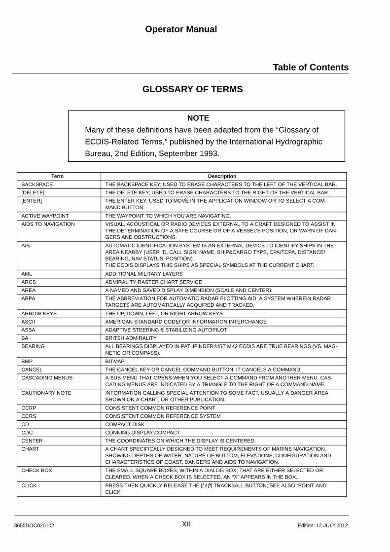
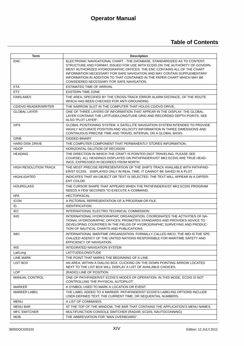
GLOSSARY OF TERMS
NOTE
Many of these definitions have been adapted from the “Glossary of
ECDIS-Related Terms,” published by the International Hydrographic
Bureau, 2nd Edition, September 1993.
Term Description
BACKSPACE THE BACKSPACE KEY; USED TO ERASE CHARACTERS TO THE LEFT OF THE VERTICAL BAR.
[DELETE] THE DELETE KEY; USED TO ERASE CHARACTERS TO THE RIGHT OF THE VERTICAL BAR.
[ENTER] THE ENTER KEY; USED TO MOVE IN THE APPLICATION WINDOW OR TO SELECT A COM-MAND BUTTON.
ACTIVE WAYPOINT THE WAYPOINT TO WHICH YOU ARE NAVIGATING.
AIDS TO NAVIGATION VISUAL, ACOUSTICAL OR RADIO DEVICES EXTERNAL TO A CRAFT DESIGNED TO ASSIST INTHE DETERMINATION OF A SAFE COURSE OR OF A VESSEL’S POSITION, OR WARN OF DAN-GERS AND OBSTRUCTIONS.
AIS AUTOMATIC IDENTIFICATION SYSTEM IS AN EXTERNAL DEVICE TO IDENTIFY SHIPS IN THEAREA NEARBY (USER ID, CALL SIGN, NAME, SHIP&CARGO TYPE, CPA/TCPA, DISTANCE/BEARING, NAV STATUS, POSITION).THE ECDIS DISPLAYS THIS SHIPS AS SPECIAL SYMBOLS AT THE CURRENT CHART.
AML ADDITIONAL MILITARY LAYERS
ARCS ADMIRALITY RASTER CHART SERVICE
AREA A NAMED AND SAVED DISPLAY DIMENSION (SCALE AND CENTER).
ARPA THE ABBREVIATION FOR AUTOMATIC RADAR PLOTTING AID. A SYSTEM WHEREIN RADARTARGETS ARE AUTOMATICALLY ACQUIRED AND TRACKED.
ARROW KEYS THE UP, DOWN, LEFT, OR RIGHT ARROW KEYS.
ASCII AMERICAN STANDARD CODEFOR INFORMATION INTERCHANGE
ASSA ADAPTIVE STEERING & STABILIZING AUTOPILOT
BA BRITSH ADMIRALITY
BEARING ALL BEARINGS DISPLAYED IN PATHFINDER/ST MK2 ECDIS ARE TRUE BEARINGS (VS. MAG-NETIC OR COMPASS).
BMP BITMAP
CANCEL THE CANCEL KEY OR CANCEL COMMAND BUTTON; IT CANCELS A COMMAND.
CASCADING MENUS A SUB MENU THAT OPENS WHEN YOU SELECT A COMMAND FROM ANOTHER MENU. CAS-CADING MENUS ARE INDICATED BY A TRIANGLE TO THE RIGHT OF A COMMAND NAME.
CAUTIONARY NOTE INFORMATION CALLING SPECIAL ATTENTION TO SOME FACT, USUALLY A DANGER AREASHOWN ON A CHART, OR OTHER PUBLICATION.
CCRP CONSISTENT COMMON REFERENCE POINT
CCRS CONSISTENT COMMON REFERENCE SYSTEM
CD COMPACT DISK
CDC CONNING DISPLAY COMPACT
CENTER THE COORDINATES ON WHICH THE DISPLAY IS CENTERED.
CHART A CHART SPECIFICALLY DESIGNED TO MEET REQUIREMENTS OF MARINE NAVIGATION,SHOWING DEPTHS OF WATER, NATURE OF BOTTOM, ELEVATIONS, CONFIGURATION ANDCHARACTERISTICS OF COAST, DANGERS AND AIDS TO NAVIGATION.
CHECK BOX THE SMALL SQUARE BOXES, WITHIN A DIALOG BOX, THAT ARE EITHER SELECTED ORCLEARED. WHEN A CHECK BOX IS SELECTED, AN “X” APPEARS IN THE BOX.
CLICK PRESS THEN QUICKLY RELEASE THE [Left] TRACKBALL BUTTON; SEE ALSO “POINT ANDCLICK”.
Operator ManualRaytheon Anschütz GmbHGermany
RNSC ECDIS
XIII 3655DOC020102Edition: 15.JAN.2013
Term Description
CLICK AND DRAG A TRACKBALL TECHNIQUE IN WHICH YOU POINT TO AN ITEM OF CHOICE, PRESS THE[Left] TRACKBALL BUTTON, MOVE THE CURSOR TO THE DESIRED POSITION, THEN RELEASETHE BUTTON.
COG COURSE OVER GROUND
COL COLOR
COMMAND A WORD OR PHRASE FOUND IN A MENU. SELECTING A COMMAND CAUSES THE APPLICA-TION TO PERFORM AN ACTION OR OPEN A DIALOG BOX.
COMMAND BUTTONS THE RECTANGULAR BOXES, WITHIN A DIALOG BOX, THAT EITHER PERFORM OR CANCELAN ACTION. “OK” AND “CANCEL” ARE TWO COMMON COMMAND BUTTONS.
COMPILE THE SELECTION, ASSEMBLY, AND GRAPHIC REPRESENTATION OF ALL RELEVANT INFORMA-TION REQUIRED FOR THE PREPARATION OF A NEW MAP/CHART. SUCH INFORMATION MAYBE DERIVED FROM OTHER MAPS/CHARTS.
COURSE THE DIRECTION IN WHICH THE SHIP IS TRAVELING. IT IS MEASURED FROM 0 (AT NORTH,CLOCKWISE TO 360). THE COURSE IS THE DIRECTION TO BE STEERED.
COURSE CONTROL ONE OF PATHFINDER/ST ECDIS’S MODES OF OPERATION. IT IS DEFINED BY AN ELEC-TRONIC HEADING, RATE OF TURN AND TURNING RADIUS, AND STEERING MAY BE DONEMANUALLY OR BY THE AUTOPILOT.
COURSE LINE THE DOTTED LINE THAT PATHFINDER/ST MK2 ECDIS DRAWS FROM THE SHIP’S POSITIONTO THE ACTIVE WAYPOINT.
COURSE MADE GOOD THE ACTUAL TRACK MADE GOOD OVER THE GROUND (THE SEABED); THE DIRECTION OFTHE POINT OF ARRIVAL FROM THE POINT OF DEPARTURE. COURSE MADE GOOD IS THEDIRECTION COMPONENT RESULTING FROM THE SHIP’S VELOCITY AND THE WATER CUR-RENT, SHOULD NOT BE CONFUSED WITH SHIP’S HEADING.
CPA CLOSEST POINT OF APPROACH
CROSS-TRACK ERROR THE PERPENDICULAR DISTANCE BETWEEN THE SHIP’S TRACK AND THE INTENDEDCOURSE. ALSO ABBREVIATED “XTE”.
CROSSHAIRS THE CURSOR SHAPE FOR POSITIONING OBJECTS IN THE DISPLAY.
CURSOR THE ON SCREEN ARROW (OR OTHER SYMBOL) USED TO PLACE AND SELECT OBJECTS ONTHE DISPLAY, AND SELECT MENUS, COMMAND AND AREAS IN DIALOG BOXES.
CURSOR BOX THE BOXES LOCATED AT THE BOTTOM LEFT OF YOUR SCREEN WHICH DISPLAY CURSORINFORMATION. THE FIRST BOX INDICATES THE “MODE” OF THE CURSOR. THE CURSORMODE DEPENDS ON THE MENU COMMAND YOU ARE CURRENTLY PERFORMING. AMONGTHE CURSOR MODES YOU WILL SEE ARE: MARKER, LINE, DELETE, CHART CENTER, LINE OFPOSITION, CONTEXT HELP, AND ZOOM IN.
DATUM A SET OF PARAMETERS SPECIFYING THE REFERENCE SURFACE OR THE REFERENCECOORDINATE SYSTEM USED FOR GEODETIC CONTROL IN THE CALCULATION OF COORDI-NATES OF POINTS ON THE EARTH.
DGPS DIFFERENTIAL GLOBAL POSITIONING SYSTEM
DIALOG BOXES RECTANGULAR BOXES DISPLAYED WHEN PATHFINDER/ST MK2 ECDIS REQUIRES MOREINFORMATION BEFORE EXECUTING A COMMAND. DIALOG BOXES ALSO DISPLAY WARNINGMESSAGES AND OTHER INFORMATION.
DIGITIZING THE PROCESS OF CONVERTING PAPER CHART INFORMATION INTO DIGITAL DATA.
DISPLAY THE PORTION OF THE SCREEN IN WHICH PATHFINDER/ST MK2 ECDIS DISPLAYS SHIPTRACKS, ROUTES, MARKERS, LINES AND ELECTRONIC CHARTS.
DNC DIGITAL NAUTICAL CHART
DOTTED BOX THE FOCUS RECTANGLE; WITHIN A DIALOG BOX, THE DOTTED TRIANGLE WHICH SIGNALSTHE ACTIVE AREA.
DR DEAD RECKONING
DVD DIGITAL VERSATILE DISC
EBL ELECTRONIC BEARING LINE
ECDIS THE ABBREVIATION FOR “ELECTRONIC CHART DISPLAY AND INFORMATION SYSTEM”.
Operator Manual
Table of Contents
XIV3655DOC020102 Edition: 12.JULY.2012
Term Description
ENC ELECTRONIC NAVIGATIONAL CHART - THE DATABASE, STANDARDIZED AS TO CONTENT,STRUCTURE AND FORMAT, ISSUED FOR USE WITH ECDIS ON THE AUTHORITY OF GOVERN-MENT AUTHORIZED HYDROGRAPHIC OFFICES. THE ENC CONTAINS ALL OF THE CHARTINFORMATION NECESSARY FOR SAFE NAVIGATION AND MAY CONTAIN SUPPLEMENTARYINFORMATION IN ADDITION TO THAT CONTAINED IN THE PAPER CHART WHICH MAY BECONSIDERED NECESSARY FOR SAFE NAVIGATION.
ETA ESTIMATED TIME OF ARRIVAL
ETZ EASTERN TIME ZONE
FAIRLANES THE AREA, SPECIFIED BY THE CROSS-TRACK ERROR ALARM DISTANCE, OF THE ROUTEWHICH HAS BEEN CHECKED FOR ANTI-GROUNDING.
CD/DVD READER/WRITER THE NARROW SLOT IN THE COMPUTER THAT HOLDS CD/DVD DRIVE..
GLOBAL LAYER ONE OF THREE LAYERS OF INFORMATION THAT APPEAR IN THE DISPLAY. THE GLOBALLAYER CONTAINS THE LATITUDE/LONGITUDE GRID AND RECORDED DEPTH POINTS. SEEALSO “PLOT LAYER”.
GPS GLOBAL POSITIONING SYSTEM. A SATELLITE NAVIGATION SYSTEM INTENDED TO PROVIDEHIGHLY ACCURATE POSITION AND VELOCITY INFORMATION IN THREE DIMENSIONS ANDCONTINUOUS PRECISE TIME AND TRAVEL INTERVAL ON A GLOBAL BASIS.
GRIB GIDDED BINARY
HARD DISK DRIVE THE COMPUTER COMPONENT THAT PERMANENTLY STORES INFORMATION.
HDOP HORIZONTAL DILUTION OF RECISION
HEADING THE DIRECTION IN WHICH THE CRAFT IS POINTED (NOT TRAVELING, PLEASE SEECOURSE). ALL HEADINGS DISPLAYED ON PATHFINDER/ST MK2 ECDIS ARE TRUE HEAD-INGS, EXPRESSED IN DEGREES FROM NORTH.
HIGH RESOLUTION TRACK THE MOST PRECISE REPRESENTATION OF THE SHIP’S TRACK AVAILABLE WITH PATHFIND-ER/ST ECDIS. DISPLAYED ONLY IN REAL TIME, IT CANNOT BE SAVED IN A PLOT.
HIGHLIGHTED INDICATES THAT AN OBJECT OR TEXT IS SELECTED. THE TEXT WILL APPEAR IN A DIFFER-ENT COLOR.
HOURGLASS THE CURSOR SHAPE THAT APPEARS WHEN THE PATHFINDER/ST MK2 ECDIS PROGRAMNEEDS A FEW SECONDS TO EXECUTE A COMMAND.
hPA HECTOPASCAL
ICON A PICTORIAL REPRESENTATION OF A PROGRAM OR FILE.
ID IDENTIFICATION
IEC INTERNATIONAL ELECTRO TECHNICAL COMMISSION
IHO INTERNATIONAL HYDROGRAPHIC ORGANIZATION. COORDINATES THE ACTIVITIES OF NA-TIONAL HYDROGRAPHIC OFFICES; PROMOTES STANDARDS AND PROVIDES ADVICE TODEVELOPING COUNTRIES IN THE FIELDS OF HYDROGRAPHIC SURVEYING AND PRODUC-TION OF NAUTICAL CHARTS AND PUBLICATIONS.
IMO INTERNATIONAL MARITIME ORGANIZATION. FORMALLY CALLED IMCO, THE IMO IS THE SPE-CIALIZED AGENCY OF THE UNITED NATIONS RESPONSIBLE FOR MARITIME SAFETY ANDEFFICIENCY OF NAVIGATION.
INS INTEGRATED NAVIGATION SYSTEM
Lat/Long LATITUDE/LONGITUDE
LINE MARK THE POINT THAT MARKS THE BEGINNING OF A LINE.
LIST BOX AN AREA, WITHIN A DIALOG BOX. CLICKING ON THE DOWN POINTING ARROW LOCATEDNEXT TO THE LIST BOX WILL DISPLAY A LIST OF AVAILABLE CHOICES.
LOP (RADIO) LINE OF POSITION
MANUAL CONTROL ONE OF PATHFINDER/ST ECDIS’S MODES OF OPERATION. IN THIS MODE, ECDIS IS NOTCONTROLLING THE PHYSICAL AUTOPILOT.
MARKER A SYMBOL USED TO MARK A LOCATION OR EVENT.
MARKER LABEL THE LABEL ADDED TO A MARKER. PATHFINDER/ST ECDIS’S LABELING OPTIONS INCLUDEUSER-DEFINED TEXT, THE CURRENT TIME, OR SEQUENTIAL NUMBERS.
MENU A LIST OF COMMANDS.
MENU BAR AT THE TOP OF THE WINDOW, THE BAR THAT CONTAINS THE APPLICATION’S MENU NAMES.
MFC SWITCHER MULTIFUNCTION CONSOLE SWITCHER (RADAR, ECDIS, NAUTOCONNING)
MOB THE ABBREVIATION FOR “MAN OVERBOARD”.
Operator ManualRaytheon Anschütz GmbHGermany
RNSC ECDIS
XV 3655DOC020102Edition: 15.JAN.2013
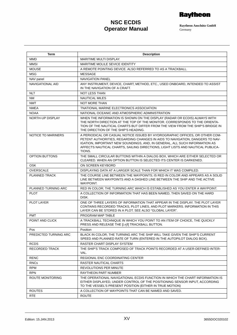
Term Description
MMD MARITIME MULTI DISPLAY.
MMSI MARITIME MOLILE SEVICE IDENTITY
MOUSE A REMOTE POINTING DEVICE. ALSO REFERRED TO AS A TRACKBALL.
MSG MESSAGE
NAV panel NAVIGATION PANEL
NAVIGATIONAL AID ANY INSTRUMENT, DEVICE, CHART, METHOD, ETC., USED ONBOARD, INTENDED TO ASSISTIN THE NAVIGATION OF A CRAFT.
NLT NOT LESS THAN
NM NAUTICAL MILES
NMT NOT MORE THAN
NMEA TNATIONAL MARINE ELECTRONICS ASSOCIATION
NOAA NATIONAL OCEANIC AND ATMOSPHERIC ADMINISTRATION
NORTH-UP DISPLAY WHEN THE INFORMATION IS SHOWN ON THE DISPLAY (RADAR OR ECDIS) ALWAYS WITHTHE NORTH DIRECTION AT THE TOP OF THE MONITOR. CORRESPONDS TO THE ORIENTA-TION OF THE NAUTICAL CHARTS BUT DIFFER FROM THE VIEW FROM THE SHIP’S BRIDGE INTHE DIRECTION OF THE SHIP’S HEADING.
NOTICE TO MARINERS A PERIODICAL OR CASUAL NOTICE ISSUED BY HYDROGRAPHIC OFFICES, OR OTHER COM-PETENT AUTHORITIES, REGARDING CHANGES IN AIDS TO NAVIGATION, DANGERS TO NAV-IGATION, IMPORTANT NEW SOUNDINGS, AND, IN GENERAL, ALL SUCH INFORMATION ASAFFECTS NAUTICAL CHARTS, SAILING DIRECTIONS, LIGHT LISTS AND NAUTICAL PUBLICA-TIONS.
OPTION BUTTONS THE SMALL CIRCULAR BUTTONS WITHIN A DIALOG BOX, WHICH ARE EITHER SELECTED ORCLEARED. WHEN AN OPTION BUTTON IS SELECTED ITS CENTER IS DARKENED.
OSK ON SCREEN KEYBORD
OVERSCALE DISPLAYING DATA AT A LARGER SCALE THAN FOR WHICH IT WAS COMPILED.
PLANNED TRACK THE COURSE LINE BETWEEN THE WAYPOINTS; IS RED IN COLOR AND APPEARS AS A SOLIDLINE BETWEEN WAYPOINTS AND A DASHED LINE BETWEEN THE SHIP AND THE ACTIVEWAYPOINT.
PLANNED TURNING ARC RED IN COLOR; THE TURNING ARC WHICH IS ESTABLISHED AS YOU ENTER A WAYPOINT.
PLOT A COLLECTION OF INFORMATION THAT HAS BEEN NAMED, THEN SAVED ON THE HARDDISK.
PLOT LAYER ONE OF THREE LAYERS OF INFORMATION THAT APPEAR IN THE DISPLAY. THE PLOT LAYERCONTAINS RECORDED TRACKS, PLOT LINES, AND PLOT MARKERS. INFORMATION IN THISLAYER CAN BE STORED IN A PLOT. SEE ALSO “GLOBAL LAYER”.
PMT PROGRAM MAP TABLE
POINT AND CLICK A TRACKBALL TECHNIQUE IN WHICH YOU POINT TO AN ITEM OF CHOICE, THE QUICKLYPRESS AND RELEASE THE [Left] TRACKBALL BUTTON.
Pos Position
PREDICTED TURNING ARC BLACK IN COLOR; THE TURNING ARC THE SHIP WILL TAKE GIVEN THE SHIP’S CURRENTSPEED AND PLANNED RATE OF TURN (ENTERED IN THE AUTOPILOT DIALOG BOX).
RCDS RASTER CHART DISPLAY SYSTEM
RECORDED TRACK THE SHIP’S TRACK COMPOSED OF TRACK POINTS RECORDED AT A USER-DEFINED INTER-VAL.
RENC REGIONAL ENC COORDINATING CENTER
RNCs RASTER NAUTICAL CHARTS
RPM REVOLUTIONS PER MINUTE
RPN RAYTHEON PART NUMBER
ROUTE MONITORING THE OPERATIONAL NAVIGATIONAL ECDIS FUNCTION IN WHICH THE CHART INFORMATION ISEITHER DISPLAYED, UNDER CONTROL OF THE POSITIONING SENSOR INPUT, ACCORDINGTO THE VESSEL’S PRESENT POSITION (EITHER IN TRUE MOTION)
ROUTES A COLLECTION OF WAYPOINTS THAT CAN BE NAMED AND SAVED.
RTE ROUTE
Operator Manual
Table of Contents
XVI3655DOC020102 Edition: 12.JULY.2012
Term Description
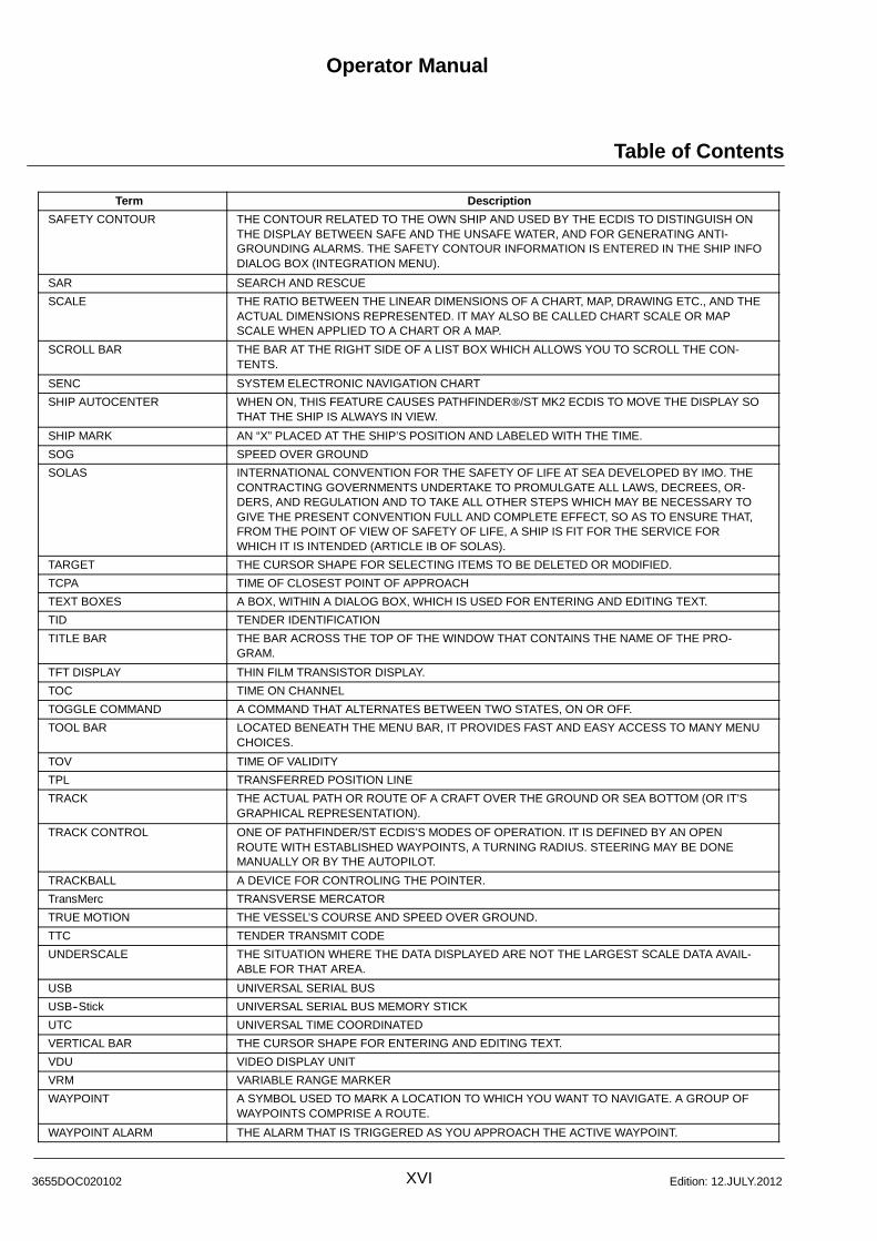
SAFETY CONTOUR THE CONTOUR RELATED TO THE OWN SHIP AND USED BY THE ECDIS TO DISTINGUISH ONTHE DISPLAY BETWEEN SAFE AND THE UNSAFE WATER, AND FOR GENERATING ANTI-GROUNDING ALARMS. THE SAFETY CONTOUR INFORMATION IS ENTERED IN THE SHIP INFODIALOG BOX (INTEGRATION MENU).
SAR SEARCH AND RESCUE
SCALE THE RATIO BETWEEN THE LINEAR DIMENSIONS OF A CHART, MAP, DRAWING ETC., AND THEACTUAL DIMENSIONS REPRESENTED. IT MAY ALSO BE CALLED CHART SCALE OR MAPSCALE WHEN APPLIED TO A CHART OR A MAP.
SCROLL BAR THE BAR AT THE RIGHT SIDE OF A LIST BOX WHICH ALLOWS YOU TO SCROLL THE CON-TENTS.
SENC SYSTEM ELECTRONIC NAVIGATION CHART
SHIP AUTOCENTER WHEN ON, THIS FEATURE CAUSES PATHFINDER/ST MK2 ECDIS TO MOVE THE DISPLAY SOTHAT THE SHIP IS ALWAYS IN VIEW.
SHIP MARK AN “X” PLACED AT THE SHIP’S POSITION AND LABELED WITH THE TIME.
SOG SPEED OVER GROUND
SOLAS INTERNATIONAL CONVENTION FOR THE SAFETY OF LIFE AT SEA DEVELOPED BY IMO. THECONTRACTING GOVERNMENTS UNDERTAKE TO PROMULGATE ALL LAWS, DECREES, OR-DERS, AND REGULATION AND TO TAKE ALL OTHER STEPS WHICH MAY BE NECESSARY TOGIVE THE PRESENT CONVENTION FULL AND COMPLETE EFFECT, SO AS TO ENSURE THAT,FROM THE POINT OF VIEW OF SAFETY OF LIFE, A SHIP IS FIT FOR THE SERVICE FORWHICH IT IS INTENDED (ARTICLE IB OF SOLAS).
TARGET THE CURSOR SHAPE FOR SELECTING ITEMS TO BE DELETED OR MODIFIED.
TCPA TIME OF CLOSEST POINT OF APPROACH
TEXT BOXES A BOX, WITHIN A DIALOG BOX, WHICH IS USED FOR ENTERING AND EDITING TEXT.
TID TENDER IDENTIFICATION
TITLE BAR THE BAR ACROSS THE TOP OF THE WINDOW THAT CONTAINS THE NAME OF THE PRO-GRAM.
TFT DISPLAY THIN FILM TRANSISTOR DISPLAY.
TOC TIME ON CHANNEL
TOGGLE COMMAND A COMMAND THAT ALTERNATES BETWEEN TWO STATES, ON OR OFF.
TOOL BAR LOCATED BENEATH THE MENU BAR, IT PROVIDES FAST AND EASY ACCESS TO MANY MENUCHOICES.
TOV TIME OF VALIDITY
TPL TRANSFERRED POSITION LINE
TRACK THE ACTUAL PATH OR ROUTE OF A CRAFT OVER THE GROUND OR SEA BOTTOM (OR IT’SGRAPHICAL REPRESENTATION).
TRACK CONTROL ONE OF PATHFINDER/ST ECDIS’S MODES OF OPERATION. IT IS DEFINED BY AN OPENROUTE WITH ESTABLISHED WAYPOINTS, A TURNING RADIUS. STEERING MAY BE DONEMANUALLY OR BY THE AUTOPILOT.
TRACKBALL A DEVICE FOR CONTROLING THE POINTER.
TransMerc TRANSVERSE MERCATOR
TRUE MOTION THE VESSEL’S COURSE AND SPEED OVER GROUND.
TTC TENDER TRANSMIT CODE
UNDERSCALE THE SITUATION WHERE THE DATA DISPLAYED ARE NOT THE LARGEST SCALE DATA AVAIL-ABLE FOR THAT AREA.
USB UNIVERSAL SERIAL BUS
USB--Stick UNIVERSAL SERIAL BUS MEMORY STICK
UTC UNIVERSAL TIME COORDINATED
VERTICAL BAR THE CURSOR SHAPE FOR ENTERING AND EDITING TEXT.
VDU VIDEO DISPLAY UNIT
VRM VARIABLE RANGE MARKER
WAYPOINT A SYMBOL USED TO MARK A LOCATION TO WHICH YOU WANT TO NAVIGATE. A GROUP OFWAYPOINTS COMPRISE A ROUTE.
WAYPOINT ALARM THE ALARM THAT IS TRIGGERED AS YOU APPROACH THE ACTIVE WAYPOINT.

Operator ManualRaytheon Anschütz GmbHGermany
RNSC ECDIS
XVII 3655DOC020102Edition: 12.JULY.2012
Term Description
(W)ECDIS WARSHIP ECDIS
WEND WORLDWIDE ELECTRONIC NAVIGATIONAL CHART BASE
WGS THE ABBREVIATION FOR “WORLD GEODETIC SYSTEM”. THIS SYSTEM WAS DEVELOPED BYTHE USA FOR SATELLITE POSITION FIXING AND RECOMMENDED BY IHO FOR HYDRO-GRAPHIC AND CARTOGRAPHIC USE. WGS84 IS THE CURRENT SYSTEM IN USE (84 REFERSTO THE YEAR).
WINDOW THE RECTANGULAR AREA IN WHICH MICROSOFT WINDOWSTM DISPLAYS PROGRAMS ANDFILES.
WMO WORLD METEOROLOGICAL ORGANISATION
WOP WHEEL OVER POINT
WO WEATHER OVERLAY
WPT WAYPOINT
XTE CROSS TRACK ERROR - THE PERPENDICULAR DISTANCE BETWEEN THE SHIP’S TRACKAND THE INTENDED COURSE.
Operator Manual Raytheon Anschütz GmbHGermany
RNSC ECDIS
1--1 3655DOC020102Edition: 03.MAR.2009
1 INTRODUCTION
ECDIS is an integrated software controlled navigation system with advanced
electronic chart capabilities including:
-- route planing
-- route monitoring
-- ground monitoring
It enables a navigator to conveniently do all navigational routines which are cur-
rently done on paper charts.
NOTE
We strongly recommend that any seafarer who uses this equipment
should have completed an appropriate traning course.
The ECDIS is designed to meet the requirements as defined by International
Maritim Organization (IMO), International Electrotechnical Commision (IEC
61174) and International Hydrographic Organization (IHO)
(see also www.IHO.FR)).
The ECDIS takes information from various shipboard sensors, such as ARPA ra-
dar, AIS information, positioning devices and echo sounders, and integrates the
information into easily interpreted visual displays.
The ECDIS supports charts from government agencies (S57, DNC and ARCS)
and private chart manufacturers, like C--Map.
Please consult your dealer for the availability of charts in your area.
NOTE
All charts are displayed in a ”North--up” orientation.
Datum is always WGS 1984 (World Geodetic System).
Operator Manual
1--23655DOC020102 Edition: 03.MAR.2009
ECDIS chart capabilities are.
C--Map: Jeppesen CM93/3, CM--ENC and “Professional +” Database
IHO: ENC and IHO--63 (encrypted)
NSG: DNC
ARCS
To handle the chart formats the computer is equipped with a CD/DVD drive.
Operator Manual Raytheon Anschütz GmbHGermany
RNSC ECDIS
1--3 3655DOC020102Edition: 03.MAR.2009
1.1 Types Of Charts
ECDIS displays the type and scale of the displayed chart in the informationpanel. As you change the scale of the display, or center the display on other
areas, the type of the chart being displayed may change, indicating that
ECDIS is displaying a more appropriate chart. If the display is centered over aregion not covered by any of the installed charts, no chart is displayed. For ex-
ample, if you zoom in on an area, ECDIS displays the chart that features the
most detailed coverage of that region; if you zoom out, it displays the chart thatfeatures broadest coverage. It also makes similar adjustments when you move
the display to the left or right, and up or down.While a chart is displayed, you may see red lines drawn on the display.
These lines designate the different fragments of the paper charts.
You may view the source of the chart; the chart name, manufacturer, date and
much more by clicking the right mouse button.
1.1.1 Charting Capabilities for S57 (CM93/3) Chart Types
Legal Equivalence With Paper Charts
In order an ECDIS to be the legal equivalent of paper charts, the following condi-
tions must be true:
The system must display official ENC (Electronic Nautical Chart), issued by
a national Hydrographic Office. The ENC must be up to date.
Regulation
The IHO S--63 data format is decoded by the ECDIS Program to pure ENC for-
mat.
ENC in S57 (93/3) format are produced and issued by national Hydrographic Of-
fices, then distributed to vessels either directly, or through a Regional ENC Coor-
dinating Center (RENC), that also performs quality checking and integration, or
through other distributors and service providers.
On the ship, S57 (93/3) data is loaded into the ECDIS in a dedicated storage
area, called the ENC database ; this shall only include ENC issued by Hydro-
graphic Offices.
Operator Manual
1--43655DOC020102 Edition: 03.MAR.2009
Since the S57 (93/3) format is not suitable for data processing, the ECDIS shall
convert the ENC into a different format (usually binary and more compact than
S57(93/3)), called the SENC (System ENC) format. A special module of the EC-
DIS software, the SENC Compiler, performs the conversion from ENC to SENC
(section 4.8 Installation (import)).
The resulting data is loaded into a separate storage area, the SENC Database,
from where it is accessed by the chart display and navigational functions of
ECDIS.
The ECDIS manufacturer may choose whatever format and database structure
for the SENC, provided that data is not downgraded in accuracy and/or contents
during the conversion from ENC to SENC.
The Jeppesen (C--Map) “Professional +” database provides special information
about tidal predication for more than 7000 tide stations and information about
more than 5000 ports certain passages and the routing network.
Following ECDIS functions are only available with the “Professional +” database:
Tidal Prediction (chapter 9.1.9).
Automatic Route Planning and Port Information (chapter 8.2.2).
1.1.2 Charting Capabilities for ENC
The provision of a timely, reliable worldwide uniform ENC data distribution ser-
vice is a major organizational challenge. The IHO developed the WEND (World--
wide Electronic Navigational Chart Database) concept to meet these require-
ments. WEND consists of two components:
A charter describes the principles governing the cooperation between Hydro-
graphic Offices e.g.:
By definition,the organization responsible for charting of an area is also
responsible for the ENC production.
The relevant standards, especially S57 must be observed; and
The rules of a recognized work quality assurance system (e.g., ISO 9000)
should be applied to data production.
Operator Manual Raytheon Anschütz GmbHGermany
RNSC ECDIS
1--5 3655DOC020102Edition: 03.MAR.2009
A conceptual schema describes a network of regional centers.
Each so--called Regional Electronic Chart Coordinating Center (RENC)
takes over the responsibility in its area for the collation of ENCs and up
dates for the region;
Through the exchange of the regional data sets and their updates between
all RENCs each RENC can offer an identical global data set for ECDIS;and
RENCs do not deliver ENCs directly to ships. RENC customers are
commercial chart data distributors who -- in analogy to paper chart
distribution -- tailor individual sets of chart data for the special needs of a
shipping company or a particular ship.
To date, two RENCs -- Primar Stavanger, based in Norway and IC--ENC, based
in the United Kingdom, are in operation. However, it has to be noted, that the
WEND concept has not been fully adopted through all ENC producing nations
yet. A number of nations are still distributing their ENCs individually (e.g. Japan
Hydrographic Office, Australian Hydrographic Office, USA -- NOAA) either
through chart data suppliers or directly.
Principally, WEND focuses on the supply and distribution of ENCs by facilitating
the establishment of services intended to satisfy the SOLAS carriage require-
ment for up--to--date charts. Within this primary purpose, ENCs are to be distrib-
uted in the encapsulation described in the S57 Standard. However, such “plain“
S57 encapsulated ENCs may become easily subject to unauthorized amend-
ment or illegal copying.
IHO has therefore issued the special publication S--63 “IHO Data Protection
Scheme“ as Standard for protection of ENCs by encryption.
Encryption is a complex technical procedure:S--63 defines security constructs
and operating procedures for the RENCs/chart data distributors and provides
specifications that allow navigation equipment manufacturers to build S--63 com-
pliant ECDIS. S--63 is already in use for ENC distribution and is supported by the
noted two RENCs. Most major ECDIS manufacturers have implemented decryp-
tion procedures in conformance with S--63 within their systems.
Operator Manual
1--63655DOC020102 Edition: 03.MAR.2009
1.1.3 Charting Capabilities for ARCS Chart Types
ARCS Seacharts (Raster--data--format)
ARCS means Admiralty Raster Chart Service. This institution scans seacharts of
the British Admiralty (BA) in a raster--data--format. Such a manner scanned sea-
charts are available on CD--ROM as Raster Nautical Charts (RNCs) with a
worldwide coverage.
A periodical update--service of the ARCS --seacharts is ensured by the
manufacturer.
A seachart in raster--data--format is divided into pixels and then stored.
On the screen of the ECDIS these pixels will be displayed.
In this way the complete (paper--) chart equivalent is displayed on the screen.
As additional information only the geographically coordinates are displayed
(after selection by courser) on the Information Panel.
Other, for seacharts typically information, as there are buoys, light beacons,
wrecks or depth information can only be read out of the displayed seachart.
The Zoom--function is reduced to 2 steps.
There is no object query possible on Raster charts.
1.1.4 Charting Capabilities for DNC Chart Types
The Digital Nautical Chart (DNC) is produced by the National Geospatial--Intelli-
gence Agency. This chart type is an unclassified, vector--based digital database
containing maritime significant features essential for safe marine navigation.
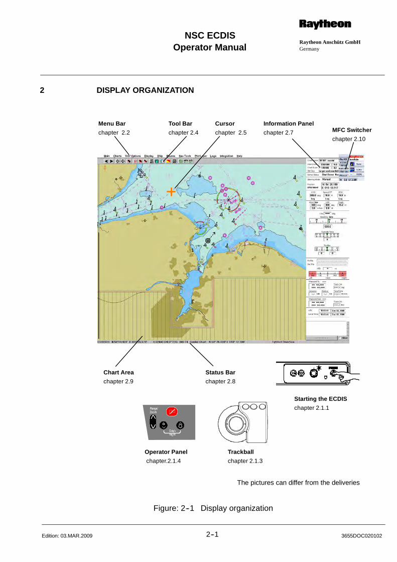
Operator ManualRaytheon Anschütz GmbHGermany
RNSC ECDIS
2--1 3655DOC020102Edition: 03.MAR.2009
2 DISPLAY ORGANIZATION
Menu Bar
chapter 2.2
Tool Bar
chapter 2.4
Cursor
chapter 2.5
Information Panel
chapter 2.7
Chart Area
chapter 2.9
Status Bar
chapter 2.8
Trackball
chapter 2.1.3
Operator Panel
chapter.2.1.4
Starting the ECDIS
chapter 2.1.1
The pictures can differ from the deliveries
MFC Switcher
chapter 2.10
Figure: 2--1 Display organization
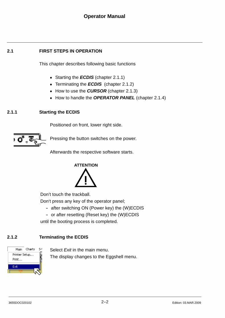
Operator Manual
2--23655DOC020102 Edition: 03.MAR.2009
2.1 FIRST STEPS IN OPERATION
This chapter describes following basic functions
D Starting the ECDIS (chapter 2.1.1)
D Terminating the ECDIS (chapter 2.1.2)
D How to use the CURSOR (chapter 2.1.3)
D How to handle the OPERATOR PANEL (chapter 2.1.4)
2.1.1 Starting the ECDIS
Positioned on front, lower right side.
Pressing the button switches on the power.
Afterwards the respective software starts.
ATTENTION
Don’t touch the trackball.
Don‘t press any key of the operator panel;
-- after switching ON (Power key) the (W)ECDIS
-- or after resetting (Reset key) the (W)ECDIS
until the booting process is completed.
2.1.2 Terminating the ECDIS
Select Exit in the main menu.
The display changes to the Eggshell menu.
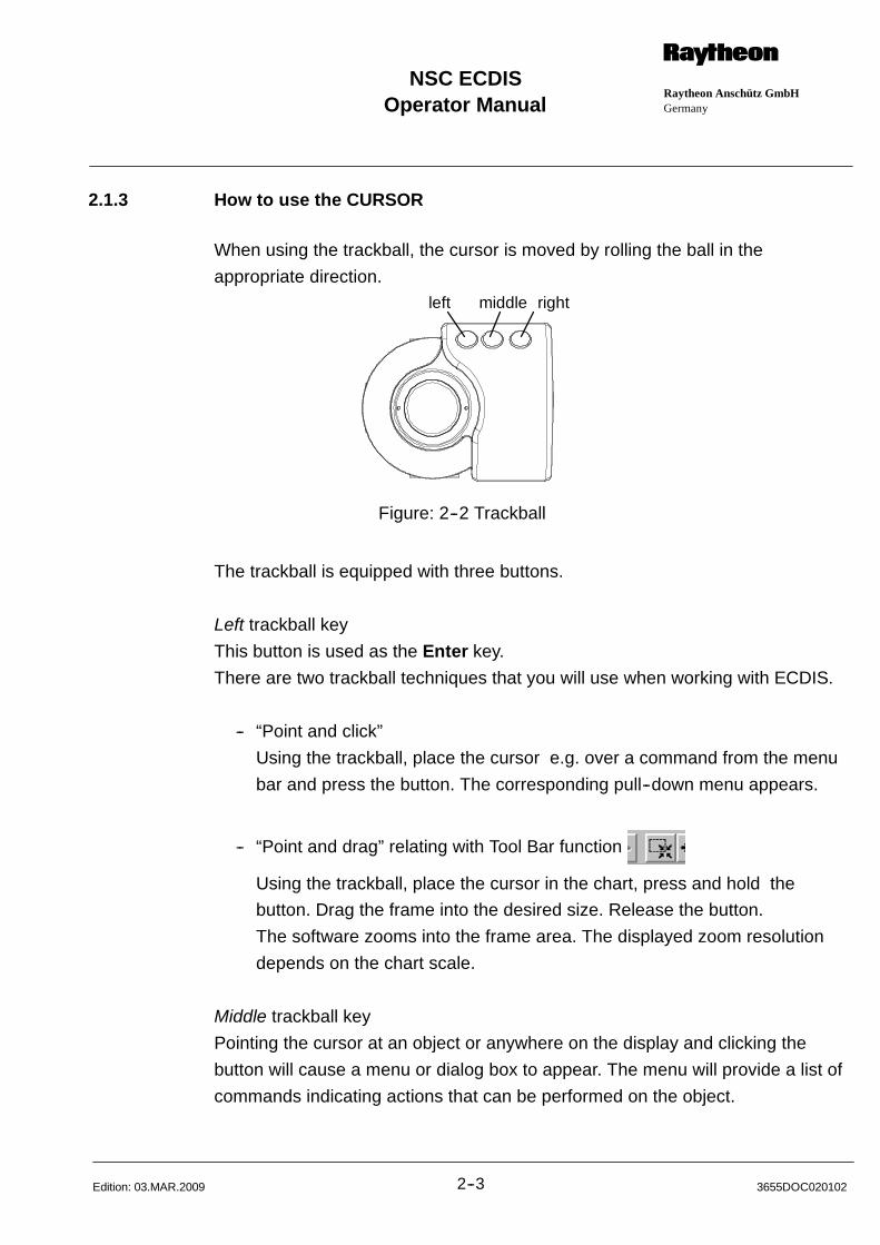
Operator ManualRaytheon Anschütz GmbHGermany
RNSC ECDIS
2--3 3655DOC020102Edition: 03.MAR.2009
2.1.3 How to use the CURSOR
When using the trackball, the cursor is moved by rolling the ball in the
appropriate direction.
Figure: 2--2 Trackball
left middle right
The trackball is equipped with three buttons.
Left trackball key
This button is used as the Enter key.
There are two trackball techniques that you will use when working with ECDIS.
-- “Point and click”
Using the trackball, place the cursor e.g. over a command from the menu
bar and press the button. The corresponding pull--down menu appears.
-- “Point and drag” relating with Tool Bar function
Using the trackball, place the cursor in the chart, press and hold the
button. Drag the frame into the desired size. Release the button.
The software zooms into the frame area. The displayed zoom resolution
depends on the chart scale.
Middle trackball key
Pointing the cursor at an object or anywhere on the display and clicking the
button will cause a menu or dialog box to appear. The menu will provide a list of
commands indicating actions that can be performed on the object.
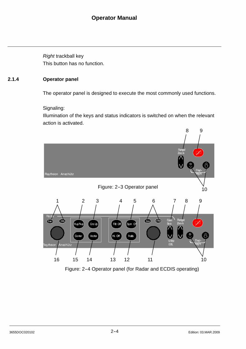
Operator Manual
2--43655DOC020102 Edition: 03.MAR.2009
Right trackball key
This button has no function.
2.1.4 Operator panel
The operator panel is designed to execute the most commonly used functions.
Signaling:
Illumination of the keys and status indicators is switched on when the relevant
action is activated.
Figure: 2--3 Operator panel
1 2 3 4 5 6 7 8 9
16 15 14 13 12 11 10
8 9
10
Figure: 2--4 Operator panel (for Radar and ECDIS operating)
Operator ManualRaytheon Anschütz GmbHGermany
RNSC ECDIS
2--5 3655DOC020102Edition: 03.MAR.2009
1/6 Status indicators, press toggle switch (7). The function activated is indicated by( ). Use the dial (16) to adjust the Gain. Use the dial (11) to adjust theSea. The Gain control adjusts the sensitivity of the radar video.The Sea control is used to suppress radar returns which are the result of radarsignals reflected from waves.
2 Radar Video displays, press button to use Head up or North up.Head up means the ship’s bow is upwards.North up means geographic north is upwards.
3 Radar Video display, press button to use Course up.Course up means the course is upwards.
4 Anti--clutter filter ON/OFF, press the button.In case of heavy clutter developing on the Radar Video, the NSC computercreates a profile of the echo. Within this profile, the received echoes aremonitored for a certain period (Scan--to--scan method). Irregular echoes aresuppressed on the Radar Video. Regular echoes are indicated on the RadarVideo.
5 Hides the symbols in the radar video.Press the button and the artificial symbols will disappear. Press again to showthe symbols.Symbols are EBLs, VRMs, PL, ARPA zones, MAPs.
6/1 Status indicators, press toggle switch (7). The activated function is indicated by( ). Use the dial (11) to adjust EBL. Use the dial (16) to adjust VRM.
7 Toggle switch. Can be switched between upper position, Gain / Sea and lowerposition, VRM / EBL. See status indicators (1/6) and use dial (16) or dial (11).
8 Toggle switch. Range selection, switches the radar ranges up and down.ECDIS function: Zoom in or out.
9 Radar and ECDIS:Alarm indicator (flashing) and alarm acknowledgment
10 Radar and ECDIS:Dimmer buttons for button illumination and radar display backlight.Press both buttons to switch between Day/Night mode.
11 Dial, see 6/1.
12 Press button until the desired values is indicated. The Trails indicator changesto the next higher mode.The steps available are OFF, 1.0, 3.0, 6.0, OFF, see TRAILS toggle field in infor-mation panel.
Operator Manual
2--63655DOC020102 Edition: 03.MAR.2009
13 Press and hold the button. The Heading Line disappears during this time.
14 Press button to change VECTOR LENGTH.
15 Center to reset your own ship to the middle of the PPI or to activate OFF
Center.
16 Dial, see 1/6.
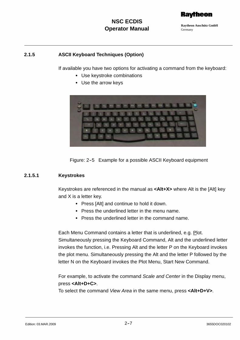
Operator ManualRaytheon Anschütz GmbHGermany
RNSC ECDIS
2--7 3655DOC020102Edition: 03.MAR.2009
2.1.5 ASCII Keyboard Techniques (Option)
If available you have two options for activating a command from the keyboard:
S Use keystroke combinations
S Use the arrow keys
Figure: 2--5 Example for a possible ASCII Keyboard equipment
2.1.5.1 Keystrokes
Keystrokes are referenced in the manual as <Alt+X> where Alt is the [Alt] key
and X is a letter key.
S Press [Alt] and continue to hold it down.
S Press the underlined letter in the menu name.
S Press the underlined letter in the command name.
Each Menu Command contains a letter that is underlined, e.g. Plot.
Simultaneously pressing the Keyboard Command, Alt and the underlined letter
invokes the function, i.e. Pressing Alt and the letter P on the Keyboard invokes
the plot menu. Simultaneously pressing the Alt and the letter P followed by the
letter N on the Keyboard invokes the Plot Menu, Start New Command.
For example, to activate the command Scale and Center in the Display menu,
press <Alt+D+C>.
To select the command View Area in the same menu, press <Alt+D+V>.
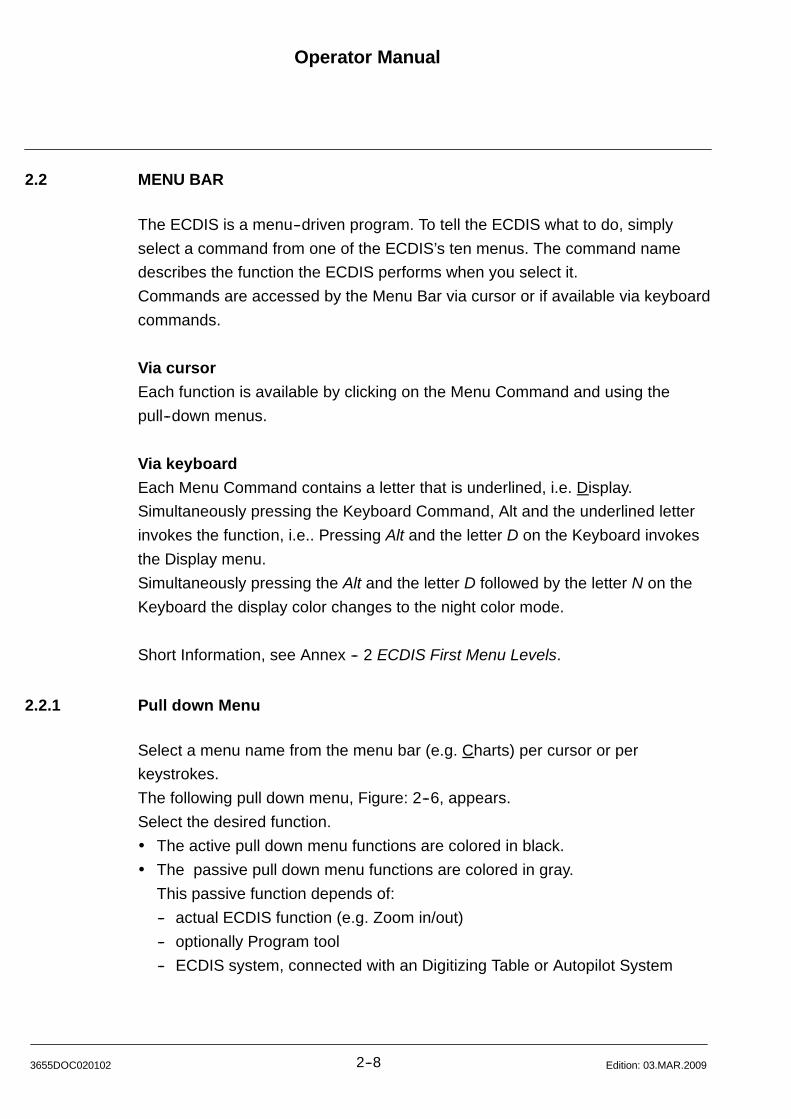
Operator Manual
2--83655DOC020102 Edition: 03.MAR.2009
2.2 MENU BAR
The ECDIS is a menu--driven program. To tell the ECDIS what to do, simply
select a command from one of the ECDIS’s ten menus. The command name
describes the function the ECDIS performs when you select it.
Commands are accessed by the Menu Bar via cursor or if available via keyboard
commands.
Via cursor
Each function is available by clicking on the Menu Command and using the
pull--down menus.
Via keyboard
Each Menu Command contains a letter that is underlined, i.e. Display.
Simultaneously pressing the Keyboard Command, Alt and the underlined letter
invokes the function, i.e.. Pressing Alt and the letter D on the Keyboard invokes
the Display menu.
Simultaneously pressing the Alt and the letter D followed by the letter N on the
Keyboard the display color changes to the night color mode.
Short Information, see Annex -- 2 ECDIS First Menu Levels.
2.2.1 Pull down Menu
Select a menu name from the menu bar (e.g. Charts) per cursor or per
keystrokes.
The following pull down menu, Figure: 2--6, appears.
Select the desired function.
The active pull down menu functions are colored in black.
The passive pull down menu functions are colored in gray.
This passive function depends of:
-- actual ECDIS function (e.g. Zoom in/out)
-- optionally Program tool
-- ECDIS system, connected with an Digitizing Table or Autopilot System
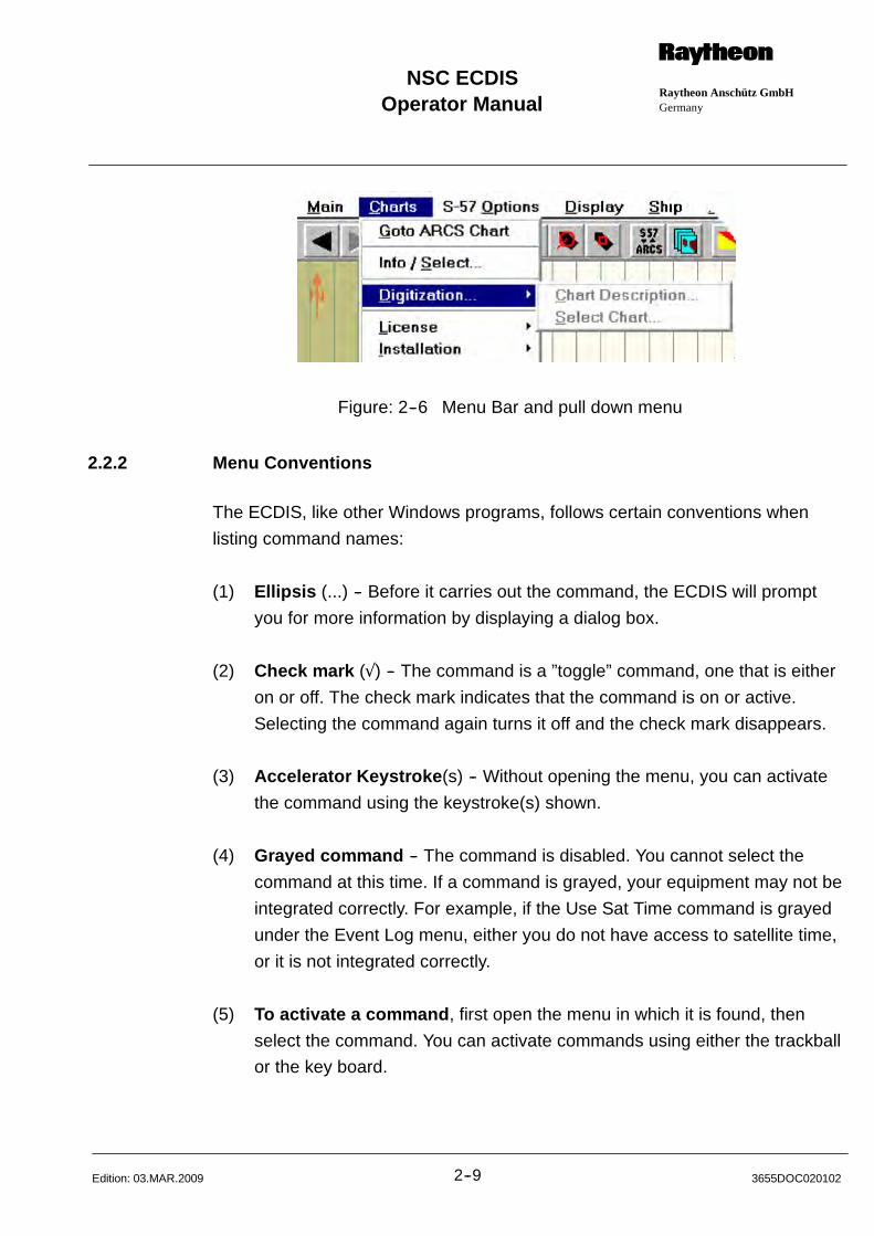
Operator ManualRaytheon Anschütz GmbHGermany
RNSC ECDIS
2--9 3655DOC020102Edition: 03.MAR.2009
Figure: 2--6 Menu Bar and pull down menu
2.2.2 Menu Conventions
The ECDIS, like other Windows programs, follows certain conventions when
listing command names:
(1) Ellipsis (...) -- Before it carries out the command, the ECDIS will prompt
you for more information by displaying a dialog box.
(2) Check mark () -- The command is a ”toggle” command, one that is either
on or off. The check mark indicates that the command is on or active.
Selecting the command again turns it off and the check mark disappears.
(3) Accelerator Keystroke(s) -- Without opening the menu, you can activate
the command using the keystroke(s) shown.
(4) Grayed command -- The command is disabled. You cannot select the
command at this time. If a command is grayed, your equipment may not be
integrated correctly. For example, if the Use Sat Time command is grayed
under the Event Log menu, either you do not have access to satellite time,
or it is not integrated correctly.
(5) To activate a command, first open the menu in which it is found, then
select the command. You can activate commands using either the trackball
or the key board.

Operator Manual
2--103655DOC020102 Edition: 03.MAR.2009
(6) The Screen Keyboards -- ECDIS without Control Panel --
This situation is recognized by the ECDIS software. On selecting an editing
field, a context related keyboard (Figure: 2--7) appears.
The operation is effectied via trackball.
prepared for editing anumerical values only
prepared for editingLatitude values only
prepared for editing aLongitude values only
prepared for editingHexadecimal values only
prepared for editingAlphanumerical values only
Figure: 2--7 Screen Keyboards
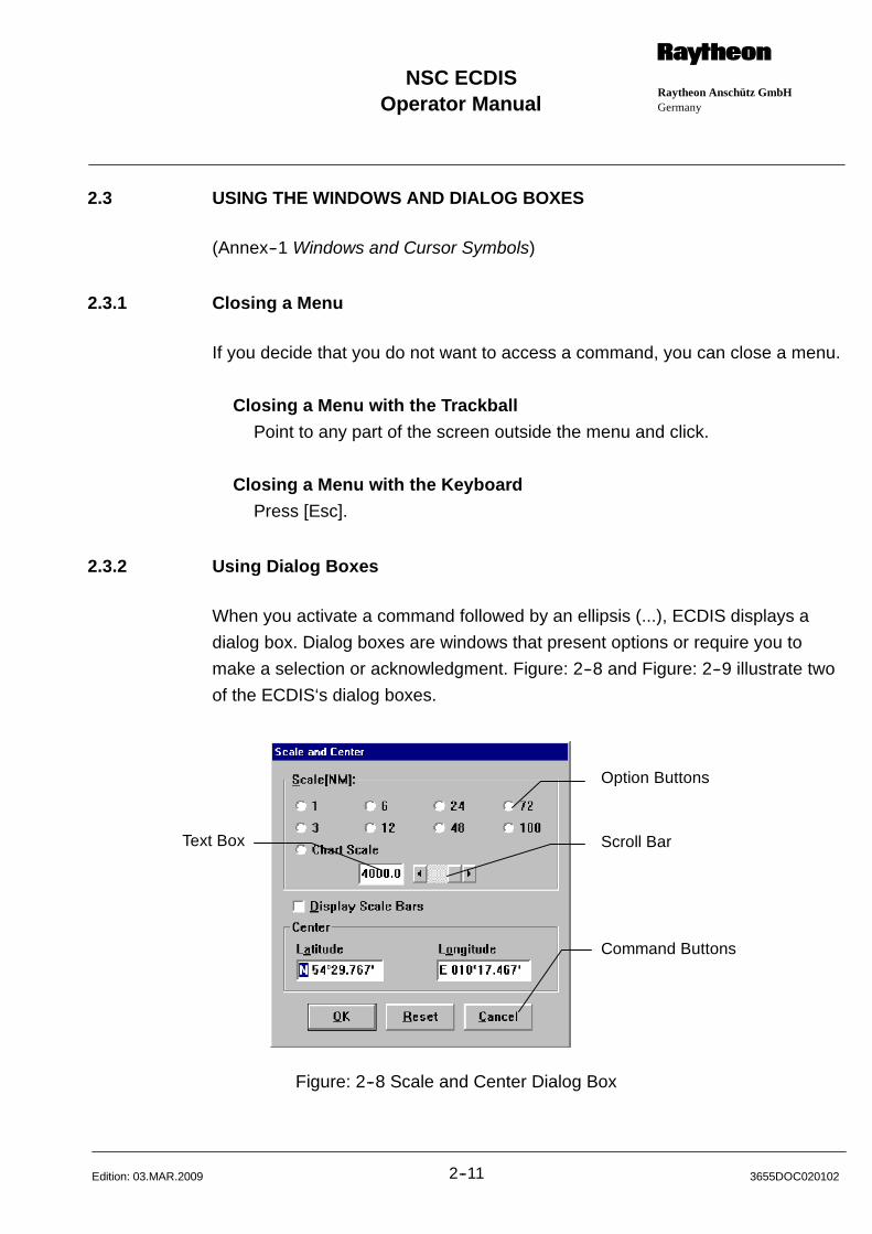
Operator ManualRaytheon Anschütz GmbHGermany
RNSC ECDIS
2--11 3655DOC020102Edition: 03.MAR.2009
2.3 USING THE WINDOWS AND DIALOG BOXES
(Annex--1 Windows and Cursor Symbols)
2.3.1 Closing a Menu
If you decide that you do not want to access a command, you can close a menu.
Closing a Menu with the Trackball
Point to any part of the screen outside the menu and click.
Closing a Menu with the Keyboard
Press [Esc].
2.3.2 Using Dialog Boxes
When you activate a command followed by an ellipsis (...), ECDIS displays a
dialog box. Dialog boxes are windows that present options or require you to
make a selection or acknowledgment. Figure: 2--8 and Figure: 2--9 illustrate two
of the ECDIS‘s dialog boxes.
Option Buttons
Text Box Scroll Bar
Command Buttons
Figure: 2--8 Scale and Center Dialog Box
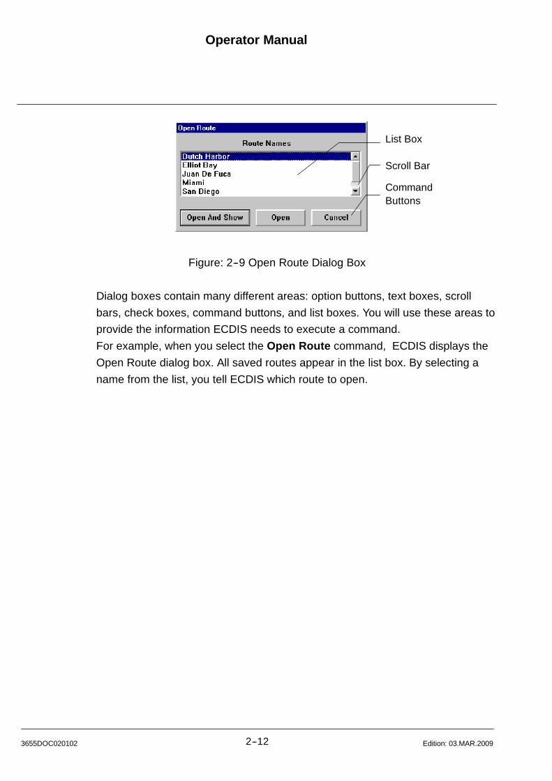
Operator Manual
2--123655DOC020102 Edition: 03.MAR.2009
List Box
Scroll Bar
CommandButtons
Figure: 2--9 Open Route Dialog Box
Dialog boxes contain many different areas: option buttons, text boxes, scroll
bars, check boxes, command buttons, and list boxes. You will use these areas to
provide the information ECDIS needs to execute a command.
For example, when you select the Open Route command, ECDIS displays the
Open Route dialog box. All saved routes appear in the list box. By selecting a
name from the list, you tell ECDIS which route to open.

Operator ManualRaytheon Anschütz GmbHGermany
RNSC ECDIS
2--13 3655DOC020102Edition: 03.MAR.2009
2.3.3 Moving in a Dialog Box
FocusRectangle
Dottedbox
Figure: 2--10 Save Event in a Dialog Box
All dialog boxes contain a focus rectangle (dotted box) (focus rectangle) that
appears either within an area or around its name, Figure: 2--10 (above). The
focus rectangle indicates which area is ”active”. For example, in the dialog box
( Figure: 2--11), the active area is the Aids to Nav. -- brief check box. The active
area may also be highlighted (i.e., darkened).
2.3.3.1 Moving the Focus Rectangle (dotted box) with Trackball
Point and click on the desired area or item.
2.3.3.2 Moving the Focus Rectangle (dotted box) with Keyboard
1) Press [Tab]. Generally, this moves the box from left to right and from top to
bottom.
2) Press <Shift+Tab> to move the box in the opposite direction.
To move directly to an area, press [Alt] plus the underlined letter in an area or
group name. For example, you may press <Alt+A> to move to the Latitude box
in the Scale and Center dialog box.
If several areas are grouped together in a box (this is common for option buttons
and check boxes), use the arrow keys to move within the box.
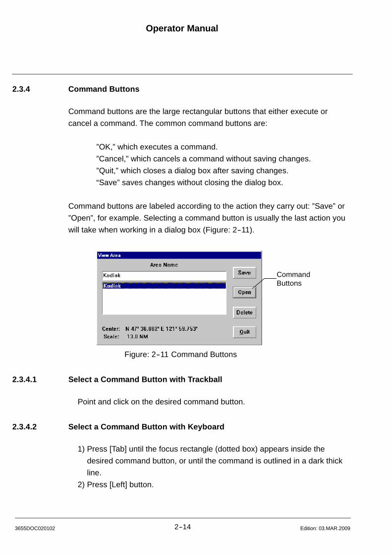
Operator Manual
2--143655DOC020102 Edition: 03.MAR.2009
2.3.4 Command Buttons
Command buttons are the large rectangular buttons that either execute or
cancel a command. The common command buttons are:
”OK,” which executes a command.
”Cancel,” which cancels a command without saving changes.
”Quit,” which closes a dialog box after saving changes.
“Save” saves changes without closing the dialog box.
Command buttons are labeled according to the action they carry out: ”Save” or
”Open”, for example. Selecting a command button is usually the last action you
will take when working in a dialog box (Figure: 2--11).
CommandButtons
Figure: 2--11 Command Buttons
2.3.4.1 Select a Command Button with Trackball
Point and click on the desired command button.
2.3.4.2 Select a Command Button with Keyboard
1) Press [Tab] until the focus rectangle (dotted box) appears inside the
desired command button, or until the command is outlined in a dark thick
line.
2) Press [Left] button.

Operator ManualRaytheon Anschütz GmbHGermany
RNSC ECDIS
2--15 3655DOC020102Edition: 03.MAR.2009
2.3.5 List Boxes and Scroll Bars
List boxes display a list of choices ( Figure: 2--12). For example, when you
choose the Open Route command, the Open Route dialog box appears.
Scroll bar
Figure: 2--12 Open Route List Box
In the list box are the names of all the routes saved in the route list. You can
select the route that you want to open from the list. When a list contains more
items than can be displayed in the list box, Windows adds a scroll bar to the right
side of the box.
Use the scroll bar to move the list up or down until hidden items become visible.
These scroll bars can be activated with the trackball or with the directional keys
on your keyboard.
2.3.5.1 Select an Item in a List Box with Trackball
1) To reveal hidden information, click on the scroll bar arrow that points in the
direction in which you want to scroll the list.
2) Point and click on the desired item.
NOTE
If you want to scroll through the list rapidly, use the small square -- called a
”thumb”--located between the arrows of the scroll bar. Point to the
”thumb”, press and hold down the [Left] button, then move the trackball so
that the ”thumb” slides along the scroll bar.
Release the trackball button.
Operator Manual
2--163655DOC020102 Edition: 03.MAR.2009
2.3.5.2 Select an Item in a List Box with Keyboard
1) Press [Tab] until one of the items in the list box (usually the first item) is
outlined with the focus rectangle (dotted box).
2) Use the arrow or the [PgUp]/[PgDn] keys to move up and down the list.
Stop when the desired item is highlighted. Then use the tab key to move
the focus rectangle (dotted box) to the command button and press [Left].
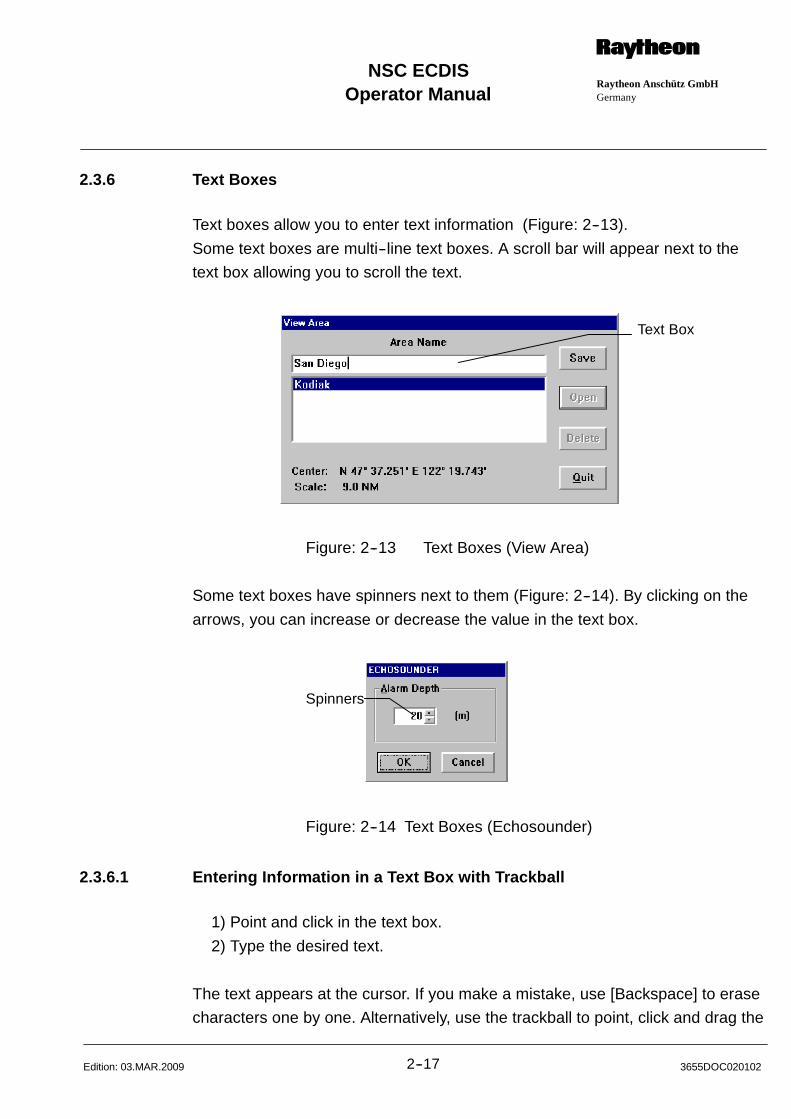
Operator ManualRaytheon Anschütz GmbHGermany
RNSC ECDIS
2--17 3655DOC020102Edition: 03.MAR.2009
2.3.6 Text Boxes
Text boxes allow you to enter text information (Figure: 2--13).
Some text boxes are multi--line text boxes. A scroll bar will appear next to the
text box allowing you to scroll the text.
Text Box
Figure: 2--13 Text Boxes (View Area)
Some text boxes have spinners next to them (Figure: 2--14). By clicking on the
arrows, you can increase or decrease the value in the text box.
Spinners
Figure: 2--14 Text Boxes (Echosounder)
2.3.6.1 Entering Information in a Text Box with Trackball
1) Point and click in the text box.
2) Type the desired text.
The text appears at the cursor. If you make a mistake, use [Backspace] to erase
characters one by one. Alternatively, use the trackball to point, click and drag the
Operator Manual
2--183655DOC020102 Edition: 03.MAR.2009
cursor over the incorrect text (the text you select is highlighted).
When you start typing new text, the selected text disappears.
2.3.6.2 Entering Information in a Text Box with Keyboard
1) Press [Tab] until the cursor appears in the text box.
If the box already contains text, the text appears highlighted. Unless you
reposition the cursor by pressing the right or left arrow keys, the highlighted text
will be replaced by the text you enter.
2) Type the desired text.
The text appears at the cursor. If you make a mistake, use [Backspace] to erase
characters one by one.

Operator ManualRaytheon Anschütz GmbHGermany
RNSC ECDIS
2--19 3655DOC020102Edition: 03.MAR.2009
2.3.7 Using Option Buttons
Option buttons are the small circular buttons with labels beside them. Option
buttons are either selected or cleared. Selected option buttons have dark
centers; cleared option buttons have empty centers. Option buttons are usually
mutually exclusive -- that is, only one button in a group can be selected at a time.
Option Buttons
Figure: 2--15 Option Buttons
2.3.7.1 Select or Clear an Option Button with Trackball
Point and click on the option button or its label.
2.3.7.2 Select or Clear an Option Button with Keyboard
Press [Tab] until the focus rectangle (dotted box) surrounds the label of the
option button.
Or, if multiple option buttons are grouped together in a box, press [Tab] until the
focus rectangle (dotted box) outlines the label of one of the buttons in the group.
Then, use the arrow keys to move from one option button to the next. As you
move from button to button, they are alternately selected, then cleared.
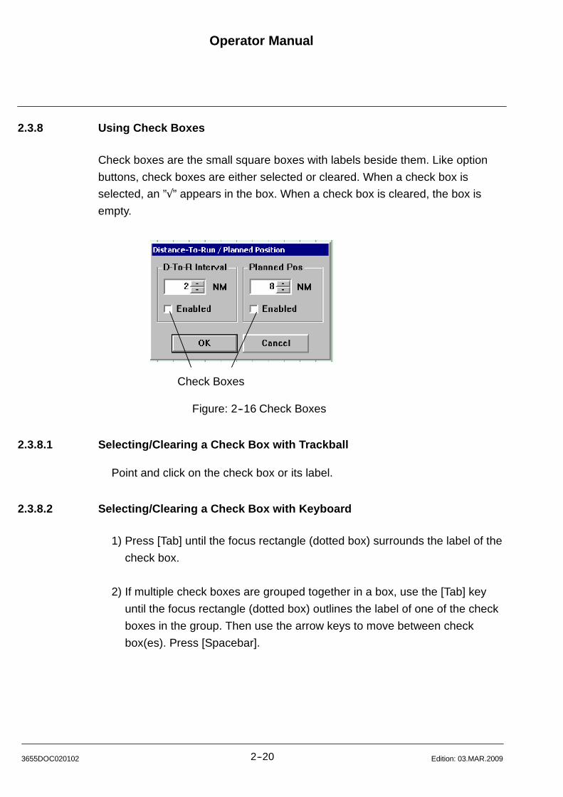
Operator Manual
2--203655DOC020102 Edition: 03.MAR.2009
2.3.8 Using Check Boxes
Check boxes are the small square boxes with labels beside them. Like option
buttons, check boxes are either selected or cleared. When a check box is
selected, an ”” appears in the box. When a check box is cleared, the box is
empty.
Check Boxes
Figure: 2--16 Check Boxes
2.3.8.1 Selecting/Clearing a Check Box with Trackball
Point and click on the check box or its label.
2.3.8.2 Selecting/Clearing a Check Box with Keyboard
1) Press [Tab] until the focus rectangle (dotted box) surrounds the label of the
check box.
2) If multiple check boxes are grouped together in a box, use the [Tab] key
until the focus rectangle (dotted box) outlines the label of one of the check
boxes in the group. Then use the arrow keys to move between check
box(es). Press [Spacebar].
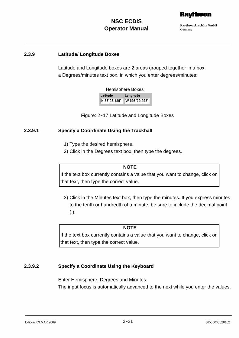
Operator ManualRaytheon Anschütz GmbHGermany
RNSC ECDIS
2--21 3655DOC020102Edition: 03.MAR.2009
2.3.9 Latitude/ Longitude Boxes
Latitude and Longitude boxes are 2 areas grouped together in a box:
a Degrees/minutes text box, in which you enter degrees/minutes;
Hemisphere Boxes
Figure: 2--17 Latitude and Longitude Boxes
2.3.9.1 Specify a Coordinate Using the Trackball
1) Type the desired hemisphere.
2) Click in the Degrees text box, then type the degrees.
NOTE
If the text box currently contains a value that you want to change, click on
that text, then type the correct value.
3) Click in the Minutes text box, then type the minutes. If you express minutes
to the tenth or hundredth of a minute, be sure to include the decimal point
(.).
NOTE
If the text box currently contains a value that you want to change, click on
that text, then type the correct value.
2.3.9.2 Specify a Coordinate Using the Keyboard
Enter Hemisphere, Degrees and Minutes.
The input focus is automatically advanced to the next while you enter the values.
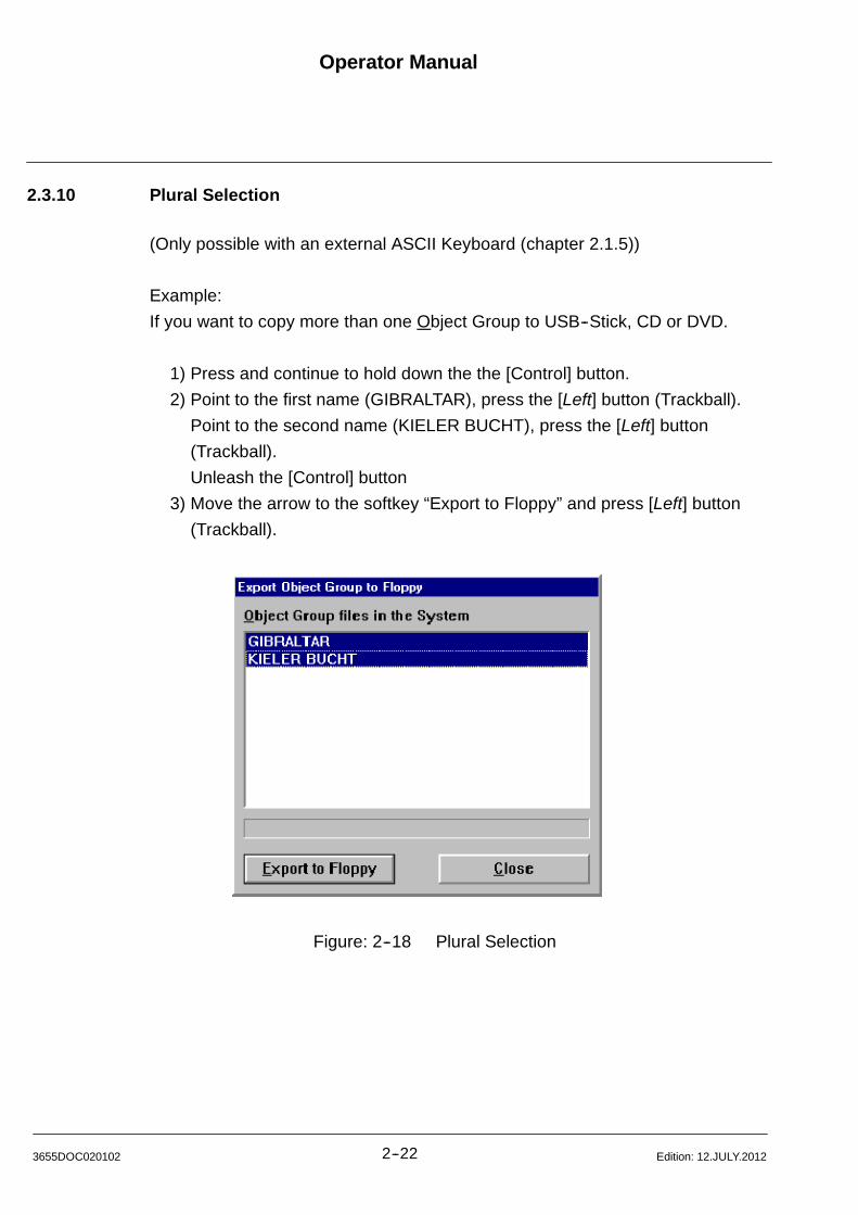
Operator Manual
2--223655DOC020102 Edition: 12.JULY.2012
2.3.10 Plural Selection
(Only possible with an external ASCII Keyboard (chapter 2.1.5))
Example:
If you want to copy more than one Object Group to USB--Stick, CD or DVD.
1) Press and continue to hold down the the [Control] button.
2) Point to the first name (GIBRALTAR), press the [Left] button (Trackball).
Point to the second name (KIELER BUCHT), press the [Left] button
(Trackball).
Unleash the [Control] button
3) Move the arrow to the softkey “Export to Floppy” and press [Left] button
(Trackball).
Figure: 2--18 Plural Selection
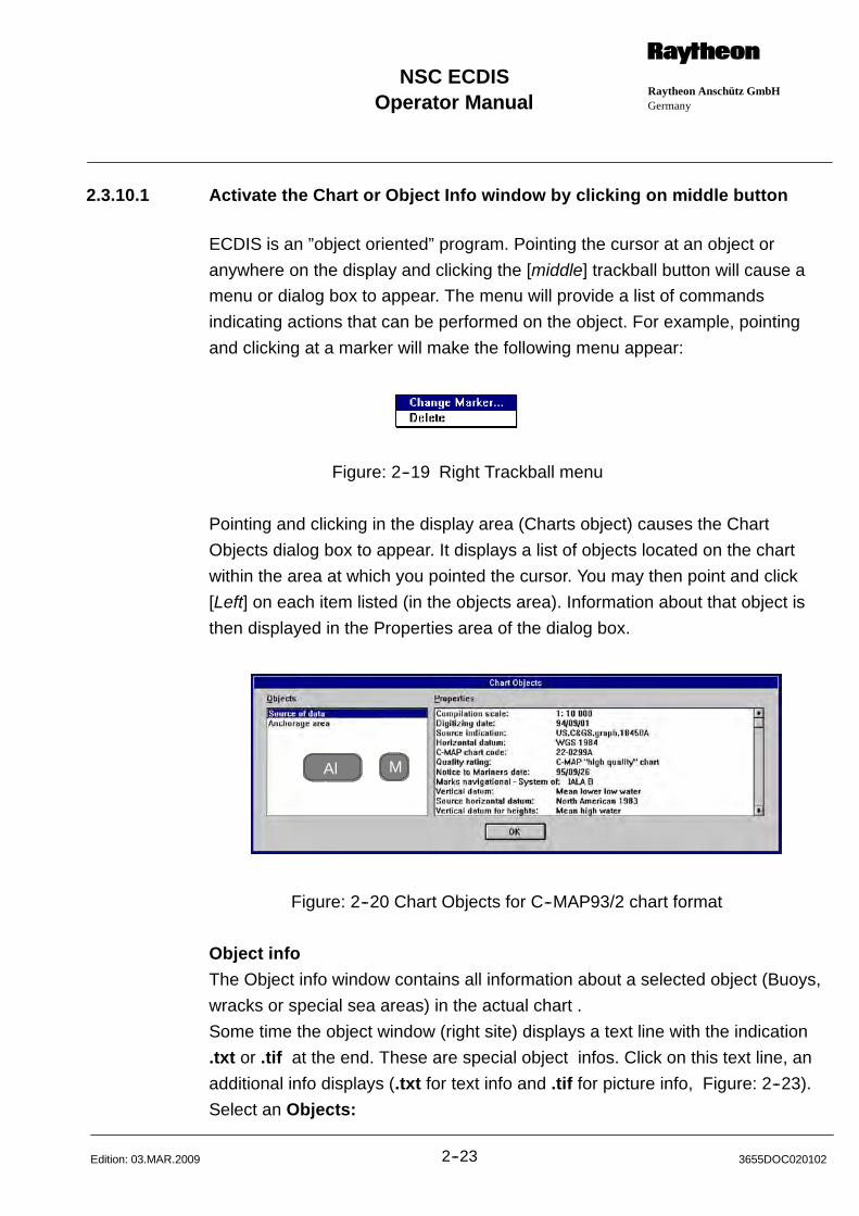
Operator ManualRaytheon Anschütz GmbHGermany
RNSC ECDIS
2--23 3655DOC020102Edition: 03.MAR.2009
2.3.10.1 Activate the Chart or Object Info window by clicking on middle button
ECDIS is an ”object oriented” program. Pointing the cursor at an object or
anywhere on the display and clicking the [middle] trackball button will cause a
menu or dialog box to appear. The menu will provide a list of commands
indicating actions that can be performed on the object. For example, pointing
and clicking at a marker will make the following menu appear:
Figure: 2--19 Right Trackball menu
Pointing and clicking in the display area (Charts object) causes the Chart
Objects dialog box to appear. It displays a list of objects located on the chart
within the area at which you pointed the cursor. You may then point and click
[Left] on each item listed (in the objects area). Information about that object is
then displayed in the Properties area of the dialog box.
Alt
M
Figure: 2--20 Chart Objects for C--MAP93/2 chart format
Object info
The Object info window contains all information about a selected object (Buoys,
wracks or special sea areas) in the actual chart .
Some time the object window (right site) displays a text line with the indication
.txt or .tif at the end. These are special object infos. Click on this text line, an
additional info displays (.txt for text info and .tif for picture info, Figure: 2--23).
Select an Objects:
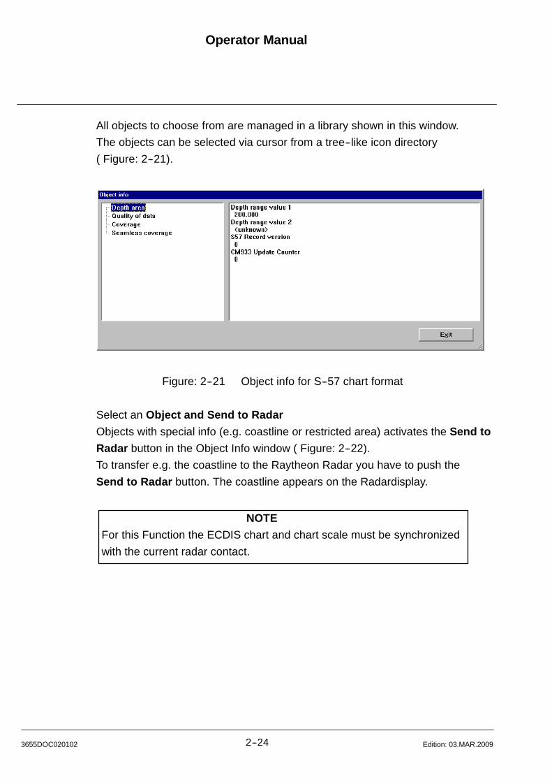
Operator Manual
2--243655DOC020102 Edition: 03.MAR.2009
All objects to choose from are managed in a library shown in this window.
The objects can be selected via cursor from a tree--like icon directory
( Figure: 2--21).
Figure: 2--21 Object info for S--57 chart format
Select an Object and Send to Radar
Objects with special info (e.g. coastline or restricted area) activates the Send to
Radar button in the Object Info window ( Figure: 2--22).
To transfer e.g. the coastline to the Raytheon Radar you have to push the
Send to Radar button. The coastline appears on the Radardisplay.
NOTE
For this Function the ECDIS chart and chart scale must be synchronized
with the current radar contact.
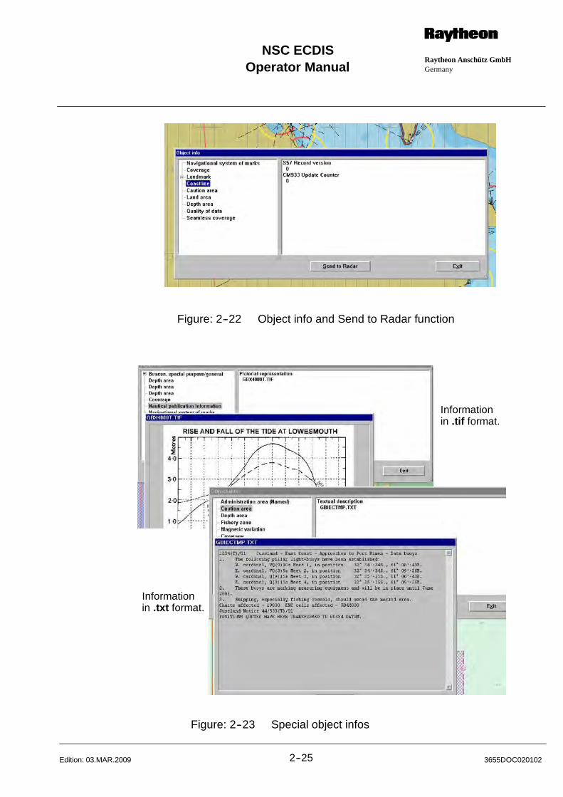
Operator ManualRaytheon Anschütz GmbHGermany
RNSC ECDIS
2--25 3655DOC020102Edition: 03.MAR.2009
Figure: 2--22 Object info and Send to Radar function
Informationin .tif format.
Informationin .txt format.
Figure: 2--23 Special object infos

Operator Manual
2--263655DOC020102 Edition: 15.JAN.2013
2.4 TOOL BAR
The toolbar, Figure: 2--24, (below) provides quick access to many ECDIS
commands.
1 2 3 4 5 6 7 8 9 11 12 13 14 15 16 17 18 1910 20
21 22
Figure: 2--24 Tool Bar
1) Previous View -- Retrieves the view which was displayed prior to the current
view. ECDIS is capable of remembering up to 30 views.
2) Next View -- Opens the view which was displayed after the current view.
ECDIS is capable of remembering up to 30 views.
3) Free Zoom In -- Zooms into the frame area using the trackball “Point
and drag” chapter 2.1.3. The displayed zoom resolution depends on the
chart scale.
4) Zoom In -- Zooms in the display, keeping the same “center” location.
Please see “The Zoom Feature”, chapter 6.1.1.
5) Zoom Out -- Redraws the current view at a scale one--and--one--half times
larger. Please see “The Zoom Feature”, chapter 6.1.1.
6) Center on Ship -- Centers the display on the ship‘s location. Please see
“Tunning ON or OFF Autocenter”, chapter 6.1.6.1.
7) Free EBL -- Allows you to draw an electronic bearing line which displays the
range and bearing from one point to another. Please see “Electronic
Bearing Line”, chapter 9.1.1.
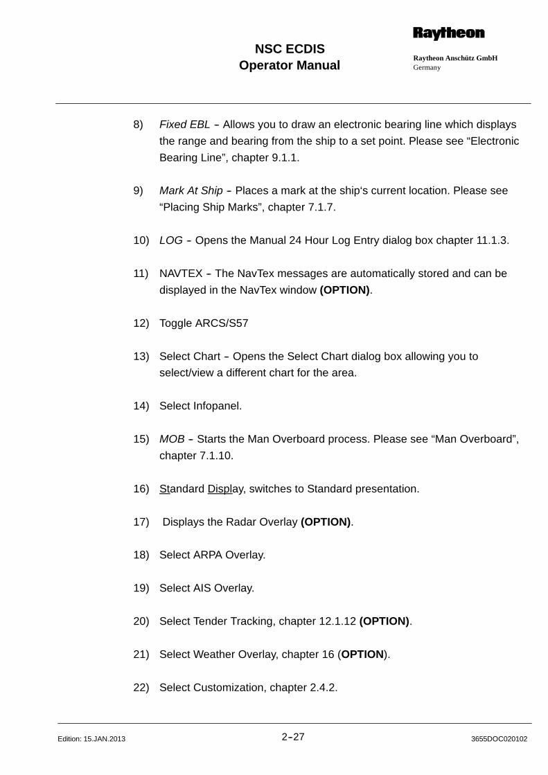
Operator ManualRaytheon Anschütz GmbHGermany
RNSC ECDIS
2--27 3655DOC020102Edition: 15.JAN.2013
8) Fixed EBL -- Allows you to draw an electronic bearing line which displays
the range and bearing from the ship to a set point. Please see “Electronic
Bearing Line”, chapter 9.1.1.
9) Mark At Ship -- Places a mark at the ship‘s current location. Please see
“Placing Ship Marks”, chapter 7.1.7.
10) LOG -- Opens the Manual 24 Hour Log Entry dialog box chapter 11.1.3.
11) NAVTEX -- The NavTex messages are automatically stored and can be
displayed in the NavTex window (OPTION).
12) Toggle ARCS/S57
13) Select Chart -- Opens the Select Chart dialog box allowing you to
select/view a different chart for the area.
14) Select Infopanel.
15) MOB -- Starts the Man Overboard process. Please see “Man Overboard”,
chapter 7.1.10.
16) Standard Display, switches to Standard presentation.
17) Displays the Radar Overlay (OPTION).
18) Select ARPA Overlay.
19) Select AIS Overlay.
20) Select Tender Tracking, chapter 12.1.12 (OPTION).
21) Select Weather Overlay, chapter 16 (OPTION).
22) Select Customization, chapter 2.4.2.
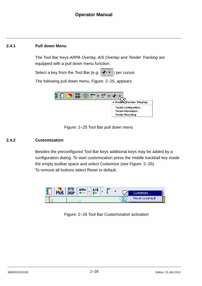
Operator Manual
2--283655DOC020102 Edition: 15.JAN.2013
2.4.1 Pull down Menu
The Tool Bar Keys ARPA Overlay, AIS Overlay and Tender Tracking are
equipped with a pull down menu function.
Select a key from the Tool Bar (e.g. ) per cursor.
The following pull down menu, Figure: 2--25, appears.
Figure: 2--25 Tool Bar pull down menu
2.4.2 Customization
Besides the preconfigured Tool Bar keys additional keys may be added by a
configuration dialog. To start customization press the middle trackball key inside
the empty toolbar space and select Customize (see Figure: 2--26).
To remove all buttons select Reset to default.
Figure: 2--26 Tool Bar Customization activation
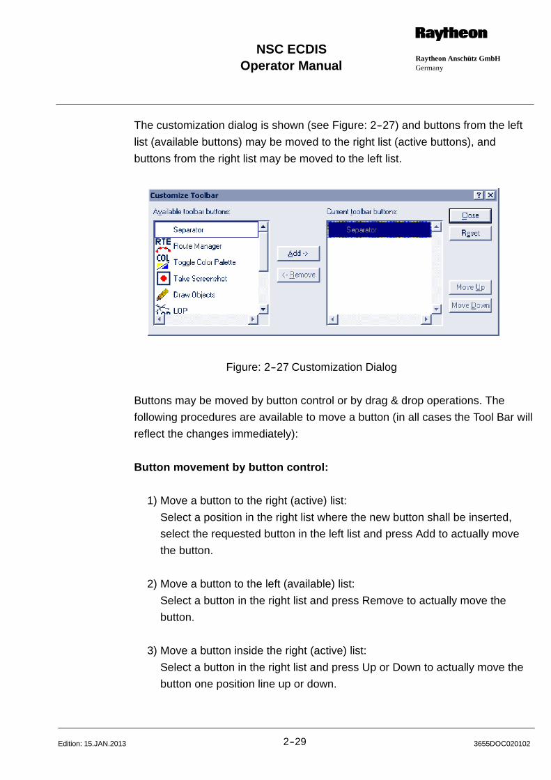
Operator ManualRaytheon Anschütz GmbHGermany
RNSC ECDIS
2--29 3655DOC020102Edition: 15.JAN.2013
The customization dialog is shown (see Figure: 2--27) and buttons from the left
list (available buttons) may be moved to the right list (active buttons), and
buttons from the right list may be moved to the left list.
Figure: 2--27 Customization Dialog
Buttons may be moved by button control or by drag & drop operations. The
following procedures are available to move a button (in all cases the Tool Bar will
reflect the changes immediately):
Button movement by button control:
1) Move a button to the right (active) list:
Select a position in the right list where the new button shall be inserted,
select the requested button in the left list and press Add to actually move
the button.
2) Move a button to the left (available) list:
Select a button in the right list and press Remove to actually move the
button.
3) Move a button inside the right (active) list:
Select a button in the right list and press Up or Down to actually move the
button one position line up or down.

Operator Manual
2--303655DOC020102 Edition: 15.JAN.2013
4) Move all buttons to the left (available) list:
Press Reset to actually move the buttons.
Button movement by drag & drop:
1) Move a button to the right (active) list:
Select a button in the left list, drag & drop it to the requested position in the
right list.
2) Move a button to the left (available) list:
Select a button in the right list, drag & drop it to any position within the left
list.
3) Move a button inside the right (active) list:
Select a button in the right list, drag & drop it to the requested position in
the right list.
Currently available buttons which are described in more detail further
down in this manual:
1 2 3 4 5 6 77 8
Figure: 2--28 Available customizable buttons
1) Route Manager -- Open Route Manager. Additional drop--down items
(Edit/Create Primary Route, Edit/Create Secondary Route, Toggle Routes,
Route Monitoring, Track Control).
2) Toggle Color Palette -- Toggle color palette between Bright--Sun and Night
settings. Additional drop--down items (Bright Sun Colors, Day Colors --
White, Day Colors -- Black, Dusk Colors, Night Colors).

Operator ManualRaytheon Anschütz GmbHGermany
RNSC ECDIS
2--31 3655DOC020102Edition: 15.JAN.2013
3) Take Screenshot -- Take an immediate screenshot. Additional drop--down
items (Screenshot).
4) Draw Objects -- Open Draw Objects Dialog.
5) LOP -- Open Line of Position Dialog.
6) Position Fix -- Open Fixed Position Dialog.
7) Exit -- Exit the Application.
8) Help -- Show the Help System.
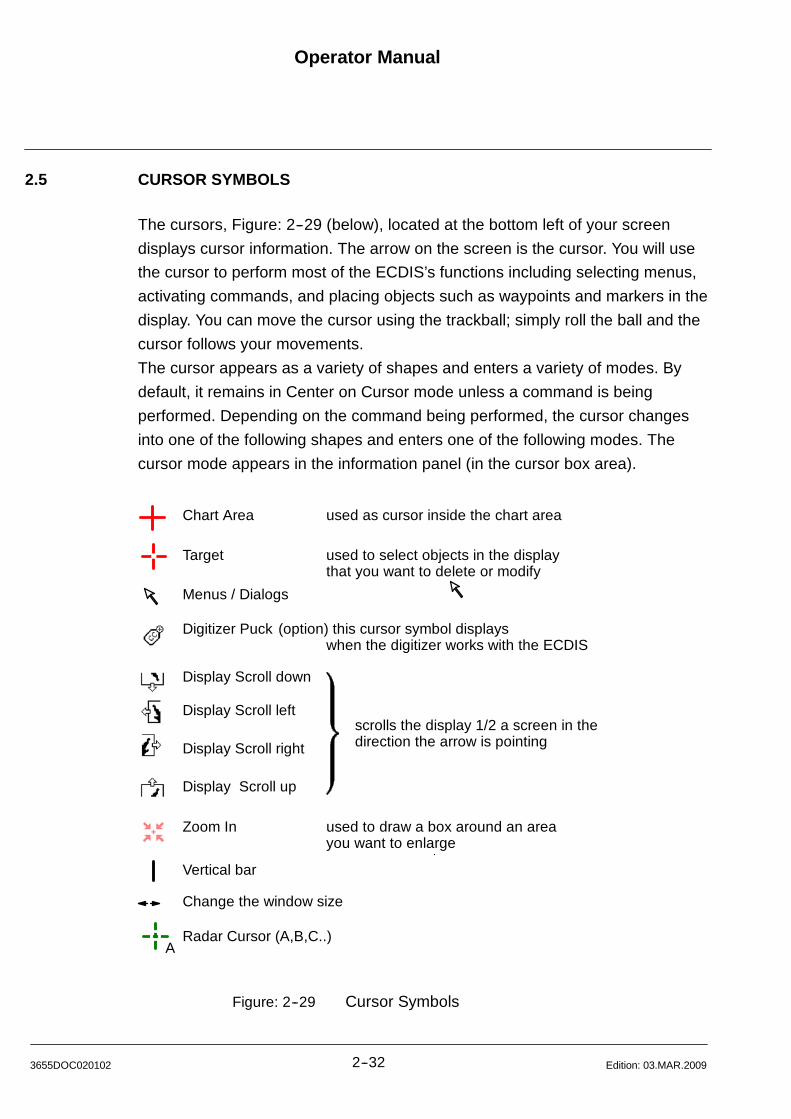
Operator Manual
2--323655DOC020102 Edition: 03.MAR.2009
2.5 CURSOR SYMBOLS
The cursors, Figure: 2--29 (below), located at the bottom left of your screen
displays cursor information. The arrow on the screen is the cursor. You will use
the cursor to perform most of the ECDIS’s functions including selecting menus,
activating commands, and placing objects such as waypoints and markers in the
display. You can move the cursor using the trackball; simply roll the ball and the
cursor follows your movements.
The cursor appears as a variety of shapes and enters a variety of modes. By
default, it remains in Center on Cursor mode unless a command is being
performed. Depending on the command being performed, the cursor changes
into one of the following shapes and enters one of the following modes. The
cursor mode appears in the information panel (in the cursor box area).
Chart Area used as cursor inside the chart area
Target used to select objects in the displaythat you want to delete or modify
Digitizer Puck (option) this cursor symbol displayswhen the digitizer works with the ECDIS
Display Scroll down
Display Scroll left
Display Scroll right
Display Scroll up
Zoom In used to draw a box around an areayou want to enlarge
Menus / Dialogs
Vertical bar
Change the window size
scrolls the display 1/2 a screen in thedirection the arrow is pointing
ARadar Cursor (A,B,C..)
Figure: 2--29 Cursor Symbols

Operator ManualRaytheon Anschütz GmbHGermany
RNSC ECDIS
2--33 3655DOC020102Edition: 03.MAR.2009
2.6 SHIP SYMBOLS IN THE CHART AREA
The ship symbol can be displayed as one of two symbols, a circle or a
rectangular ship symbol.
This symbol adjusts tothe scale of the chart.
This symbol does notadjust to the scale ofthe chart.
6min
1min
2min
3min
4min
5min
Figure: 2--30 Own Ships Symbols
2.6.1 Circle
The circular symbol is a fixed size symbol (it does not adjust to the scale of the
chart). The circular symbol appears when the ECDIS is not receiving information
from any navigational devices, or if the scale of the chart is such that the ship
cannot be drawn in its relative size. It is also used during dead reckoning
(simulation). It has a directional arrow displaying the ship‘s heading as well as a
perpendicular shipboard line marking port and starboard sides.
This arrowhead displays the expected ships position after for example 6min.
No Heading With Heading
Figure: 2--31 Own Ships Symbol (Circle)
2.6.2 Rectangular Ship
The rectangular ship symbol is not a fixed size symbol and adjusts to the scale
of the chart. This symbol is used at all times except when the ECDIS is not
receiving navigational information or when the ship cannot be drawn to scale. It
also has a directional arrow displaying the ship‘s heading and expected ship
position after desired time.
6min
1min
2min
3min
4min
5min
Figure: 2--32 Own Ships Symbol (Rectangle)
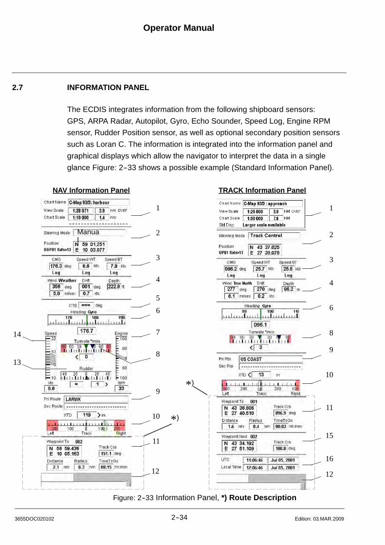
Operator Manual
2--343655DOC020102 Edition: 03.MAR.2009
2.7 INFORMATION PANEL
The ECDIS integrates information from the following shipboard sensors:
GPS, ARPA Radar, Autopilot, Gyro, Echo Sounder, Speed Log, Engine RPM
sensor, Rudder Position sensor, as well as optional secondary position sensors
such as Loran C. The information is integrated into the information panel and
graphical displays which allow the navigator to interpret the data in a single
glance Figure: 2--33 shows a possible example (Standard Information Panel).
1
14
138
2
3
4
5
6
7
9
10
11
12
NAV Information Panel TRACK Information Panel
1
2
3
4
6
8
9
10
11
15
16
12
*)
*)
Manual
Figure: 2--33 Information Panel, *) Route Description
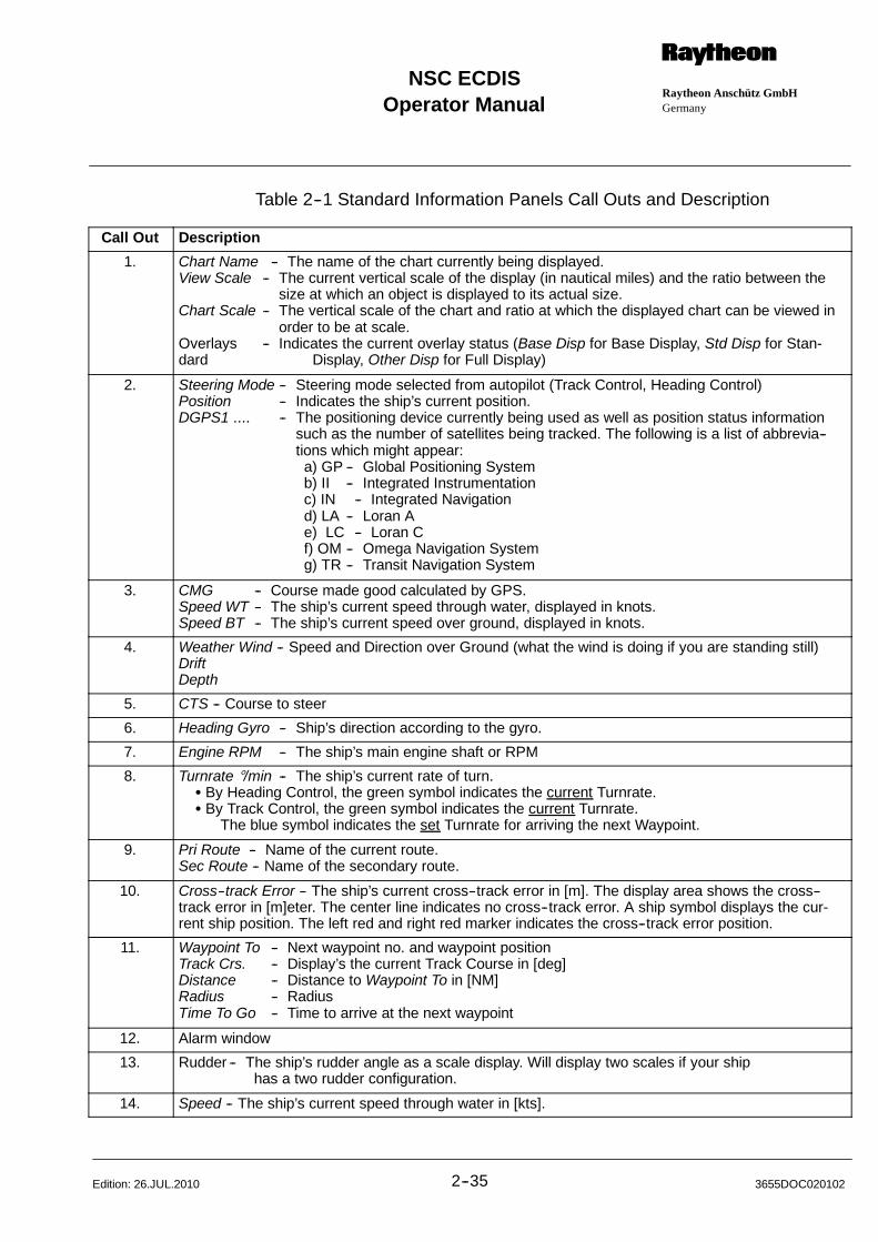
Operator ManualRaytheon Anschütz GmbHGermany
RNSC ECDIS
2--35 3655DOC020102Edition: 26.JUL.2010
Table 2--1 Standard Information Panels Call Outs and Description
Call Out Description
1. Chart Name -- The name of the chart currently being displayed.View Scale -- The current vertical scale of the display (in nautical miles) and the ratio between the
size at which an object is displayed to its actual size.Chart Scale -- The vertical scale of the chart and ratio at which the displayed chart can be viewed in
order to be at scale.Overlays -- Indicates the current overlay status (Base Disp for Base Display, Std Disp for Stan-dard Display, Other Disp for Full Display)
2. Steering Mode -- Steering mode selected from autopilot (Track Control, Heading Control)Position -- Indicates the ship’s current position.DGPS1 .... -- The positioning device currently being used as well as position status information
such as the number of satellites being tracked. The following is a list of abbrevia--tions which might appear:a) GP -- Global Positioning Systemb) II -- Integrated Instrumentationc) IN -- Integrated Navigationd) LA -- Loran Ae) LC -- Loran Cf) OM -- Omega Navigation Systemg) TR -- Transit Navigation System
3. CMG -- Course made good calculated by GPS.Speed WT -- The ship’s current speed through water, displayed in knots.Speed BT -- The ship’s current speed over ground, displayed in knots.
4. Weather Wind -- Speed and Direction over Ground (what the wind is doing if you are standing still)DriftDepth
5. CTS -- Course to steer
6. Heading Gyro -- Ship’s direction according to the gyro.
7. Engine RPM -- The ship’s main engine shaft or RPM
8. Turnrate /min -- The ship’s current rate of turn.S By Heading Control, the green symbol indicates the current Turnrate.S By Track Control, the green symbol indicates the current Turnrate.
The blue symbol indicates the set Turnrate for arriving the next Waypoint.
9. Pri Route -- Name of the current route.Sec Route -- Name of the secondary route.
10. Cross--track Error -- The ship’s current cross--track error in [m]. The display area shows the cross--track error in [m]eter. The center line indicates no cross--track error. A ship symbol displays the cur-rent ship position. The left red and right red marker indicates the cross--track error position.
11. Waypoint To -- Next waypoint no. and waypoint positionTrack Crs. -- Display’s the current Track Course in [deg]Distance -- Distance to Waypoint To in [NM]Radius -- RadiusTime To Go -- Time to arrive at the next waypoint
12. Alarm window
13. Rudder -- The ship’s rudder angle as a scale display. Will display two scales if your shiphas a two rudder configuration.
14. Speed -- The ship’s current speed through water in [kts].
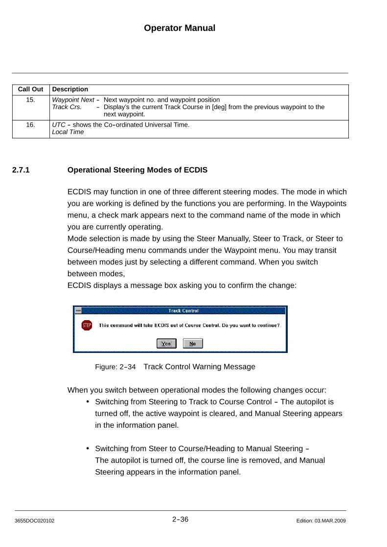
Operator Manual
2--363655DOC020102 Edition: 03.MAR.2009
Call Out Description
15. Waypoint Next -- Next waypoint no. and waypoint positionTrack Crs. -- Display’s the current Track Course in [deg] from the previous waypoint to the
next waypoint.
16. UTC -- shows the Co--ordinated Universal Time.Local Time
2.7.1 Operational Steering Modes of ECDIS
ECDIS may function in one of three different steering modes. The mode in which
you are working is defined by the functions you are performing. In the Waypoints
menu, a check mark appears next to the command name of the mode in which
you are currently operating.
Mode selection is made by using the Steer Manually, Steer to Track, or Steer to
Course/Heading menu commands under the Waypoint menu. You may transit
between modes just by selecting a different command. When you switch
between modes,
ECDIS displays a message box asking you to confirm the change:
Figure: 2--34 Track Control Warning Message
When you switch between operational modes the following changes occur:
Switching from Steering to Track to Course Control -- The autopilot is
turned off, the active waypoint is cleared, and Manual Steering appears
in the information panel.
Switching from Steer to Course/Heading to Manual Steering --
The autopilot is turned off, the course line is removed, and Manual
Steering appears in the information panel.
Operator ManualRaytheon Anschütz GmbHGermany
RNSC ECDIS
2--37 3655DOC020102Edition: 03.MAR.2009
Switching from Steering to Track to Steering to Course/Heading --
The active waypoint is cleared and ECDIS switches to Course Control
until a valid heading is entered.
Switching from Steering to Course/Heading to Steer to Track --
The course line is removed and ECDIS switches to Course Control if a
valid active waypoint is selected and the data transmission between
ECDIS and Autopilot is established (see Raytheon Autopilot
Description NP2030, NP2035).
(1) Steering Mode Manual Control
Steering is done manually. ECDIS automatically switches to Manual Steering
mode in the following situations:
When you select the Steer Manually command from Steering Mode
Selector Switch.
(2) Steering Mode Track Control
Defined by an open route with established waypoints and a turning radius.
Steering may be done manually or by the autopilot. While steering to a track, the
information panel will display the active and next waypoints position, distance,
radius and time to go.
The max. turn radius from e.g. WP1 to WP2 may not be larger how 135.
If you select the Steer to Track command while currently steering to a track, you
are temporarily switched to manual steering. ECDIS is waiting for you to provide
a new valid active waypoint. A valid active waypoint is defined by whether the
vessel can make the required turn to enter the route at that waypoint.

Operator Manual
2--383655DOC020102 Edition: 03.MAR.2009
Figure: 2--35 Information Panel Steer to Track Control
(3) Steering Mode Heading Control
Defined by an electronic heading or course over ground (course made good),
rate of turn and turning radius. Steering may be done manually or by the
autopilot. While steering to a course or heading, the information panel will or say
”Heading Control” .
When a course or heading is entered, the ship will continue following the entered
course/heading for 100NM, or until a different mode of operation is selected.
If you select the Steer to Course/Heading command while you are currently
steering to a course/heading, you continue steering to the original
course/heading until you enter a new valid heading and select ”OK”. A valid
heading is defined by whether the vessel can make the physical rate of turn.
Heading Control
Figure: 2--36 Information Panel Heading Control
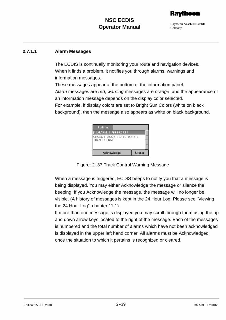
Operator ManualRaytheon Anschütz GmbHGermany
RNSC ECDIS
2--39 3655DOC020102Edition: 25.FEB.2010
2.7.1.1 Alarm Messages
The ECDIS is continually monitoring your route and navigation devices.
When it finds a problem, it notifies you through alarms, warnings and
information messages.
These messages appear at the bottom of the information panel.
Alarm messages are red, warning messages are orange, and the appearance of
an information message depends on the display color selected.
For example, if display colors are set to Bright Sun Colors (white on black
background), then the message also appears as white on black background.
Figure: 2--37 Track Control Warning Message
When a message is triggered, ECDIS beeps to notify you that a message is
being displayed. You may either Acknowledge the message or silence the
beeping. If you Acknowledge the message, the message will no longer be
visible. (A history of messages is kept in the 24 Hour Log. Please see ”Viewing
the 24 Hour Log”, chapter 11.1).
If more than one message is displayed you may scroll through them using the up
and down arrow keys located to the right of the message. Each of the messages
is numbered and the total number of alarms which have not been acknowledged
is displayed in the upper left hand corner. All alarms must be Acknowledged
once the situation to which it pertains is recognized or cleared.
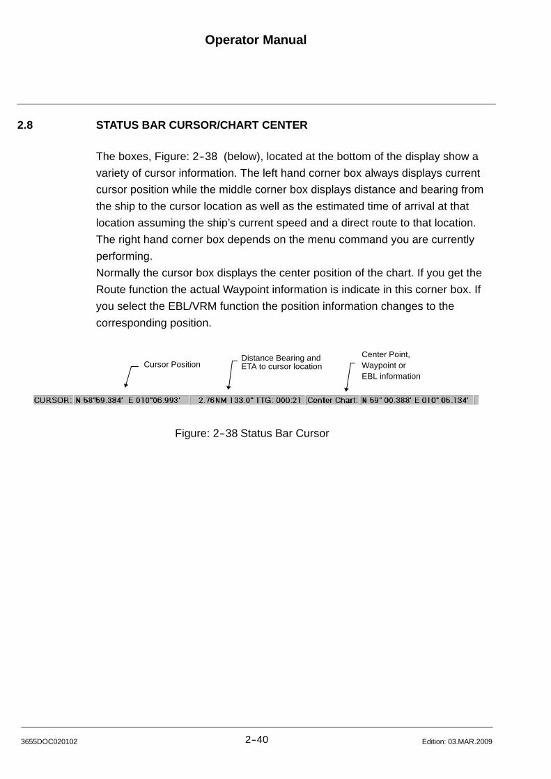
Operator Manual
2--403655DOC020102 Edition: 03.MAR.2009
2.8 STATUS BAR CURSOR/CHART CENTER
The boxes, Figure: 2--38 (below), located at the bottom of the display show a
variety of cursor information. The left hand corner box always displays current
cursor position while the middle corner box displays distance and bearing from
the ship to the cursor location as well as the estimated time of arrival at that
location assuming the ship’s current speed and a direct route to that location.
The right hand corner box depends on the menu command you are currently
performing.
Normally the cursor box displays the center position of the chart. If you get the
Route function the actual Waypoint information is indicate in this corner box. If
you select the EBL/VRM function the position information changes to the
corresponding position.
Cursor Position ETA to cursor locationDistance Bearing and Center Point,
Waypoint orEBL information
Figure: 2--38 Status Bar Cursor

Operator ManualRaytheon Anschütz GmbHGermany
RNSC ECDIS
2--41 3655DOC020102Edition: 03.MAR.2009
2.9 CHART AREA
The chart area is where the ECDIS displays ship, electronic charts symbol, and
past tracks. It is also where you will enter waypoints/routes, set markers, and
draw lines.
The display has optional latitude/longitude grid lines which cover the entire world
and are measured in degrees and minutes, with minutes expressed to the
hundredth decimal.
The degrees and minutes currently in view appear down the left side and across
the bottom of the display. You can control the appearance and location of the
display using commands in the Display menu.
The ECDIS supports charts from government agencies (S57, DNC and ARCS)
and private chart manufacturers, like C--MAP. Please consult your dealer for the
availability of charts in your area.
NOTE
All charts are displayed in a ”North--up” orientation.
Datum is always WGS 1984 (World Geodetic System).
2.9.1 Chart Boundaries
While a chart is displayed, you may see red lines drawn on the display. These
lines designate the different fragments of the paper charts. You may view the
source of the chart; the chart name, manufacturer, date, and other information
by clicking the right mouse button. When a portion of the area you are viewing is
not covered by the chart currently displayed, the area appears green in color. If
you are viewing an area of the globe for which you have no charts, the area
appears white.
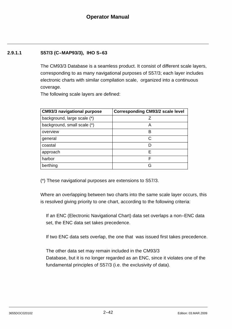
Operator Manual
2--423655DOC020102 Edition: 03.MAR.2009
2.9.1.1 S57/3 (C--MAP93/3), IHO S--63
The CM93/3 Database is a seamless product. It consist of different scale layers,
corresponding to as many navigational purposes of S57/3; each layer includes
electronic charts with similar compilation scale, organized into a continuous
coverage.
The following scale layers are defined:
CM93/3 navigational purpose Corresponding CM93/2 scale level
background, large scale (*) Z
background, small scale (*) A
overview B
general C
coastal D
approach E
harbor F
berthing G
(*) These navigational purposes are extensions to S57/3.
Where an overlapping between two charts into the same scale layer occurs, this
is resolved giving priority to one chart, according to the following criteria:
If an ENC (Electronic Navigational Chart) data set overlaps a non--ENC data
set, the ENC data set takes precedence.
If two ENC data sets overlap, the one that was issued first takes precedence.
The other data set may remain included in the CM93/3
Database, but it is no longer regarded as an ENC, since it violates one of the
fundamental principles of S57/3 (i.e. the exclusivity of data).

Operator ManualRaytheon Anschütz GmbHGermany
RNSC ECDIS
2--43 3655DOC020102Edition: 03.MAR.2009
2.9.1.2 Track Plotter
The ECDIS positions the ship on the electronic chart using information from the
GPS or other positioning sensors. The ship symbol is directional and is oriented
according to your gyro heading. An optional heading vector (an arrow) and
search light (the cone shape) are displayed projecting from the bow of the ship
symbol.
The information panel constantly displays updated information on your position,
speed, and bearing.
NOTE
The anti--grounding search light will detect and signal a warning if the ship
is about to cross a safety contour area. The length of the heading vector
determines the length of the search light, hence the ship’s warning time.
(A general ship alarm will sound if the warning is not acknowledged within
30 seconds).
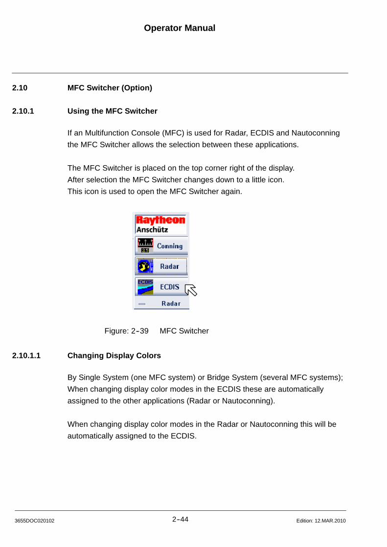
Operator Manual
2--443655DOC020102 Edition: 12.MAR.2010
2.10 MFC Switcher (Option)
2.10.1 Using the MFC Switcher
If an Multifunction Console (MFC) is used for Radar, ECDIS and Nautoconning
the MFC Switcher allows the selection between these applications.
The MFC Switcher is placed on the top corner right of the display.
After selection the MFC Switcher changes down to a little icon.
This icon is used to open the MFC Switcher again.
Figure: 2--39 MFC Switcher
2.10.1.1 Changing Display Colors
By Single System (one MFC system) or Bridge System (several MFC systems);
When changing display color modes in the ECDIS these are automatically
assigned to the other applications (Radar or Nautoconning).
When changing display color modes in the Radar or Nautoconning this will be
automatically assigned to the ECDIS.
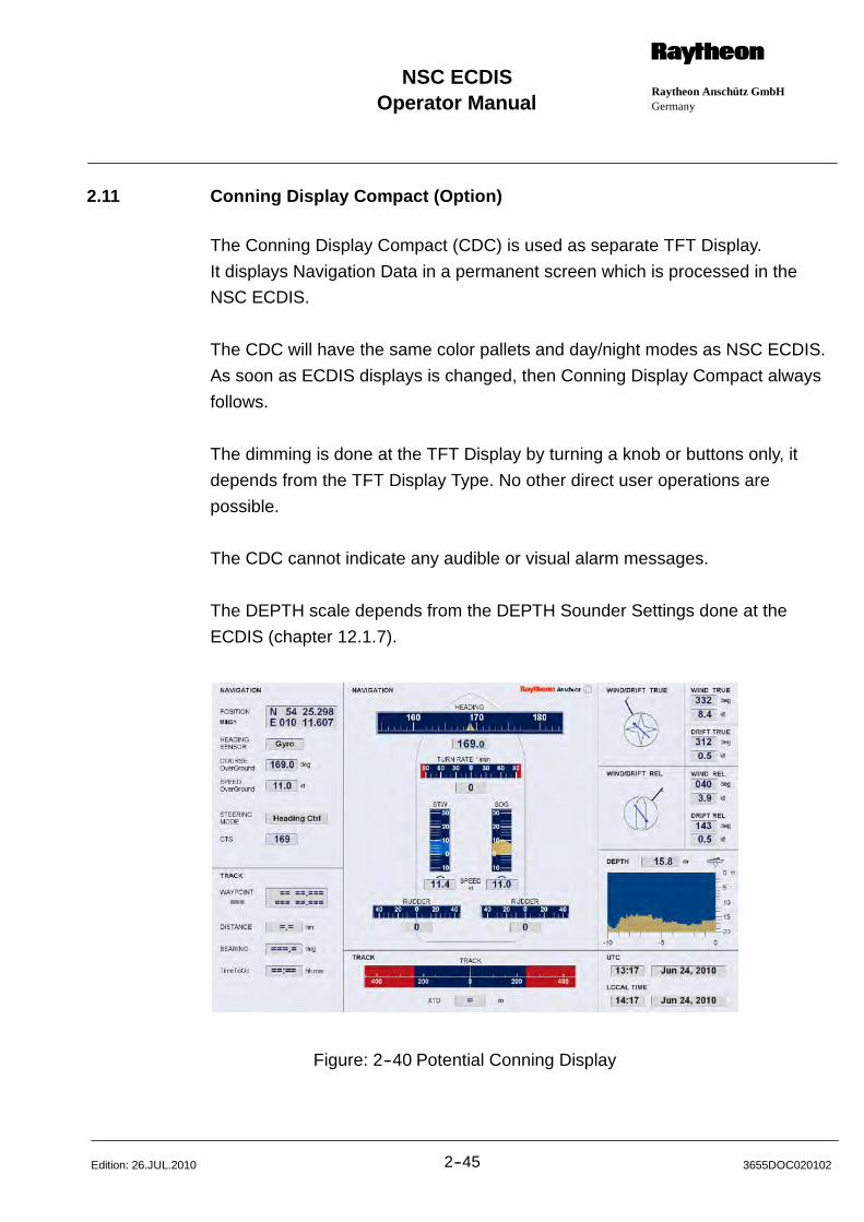
Operator ManualRaytheon Anschütz GmbHGermany
RNSC ECDIS
2--45 3655DOC020102Edition: 26.JUL.2010
2.11 Conning Display Compact (Option)
The Conning Display Compact (CDC) is used as separate TFT Display.
It displays Navigation Data in a permanent screen which is processed in the
NSC ECDIS.
The CDC will have the same color pallets and day/night modes as NSC ECDIS.
As soon as ECDIS displays is changed, then Conning Display Compact always
follows.
The dimming is done at the TFT Display by turning a knob or buttons only, it
depends from the TFT Display Type. No other direct user operations are
possible.
The CDC cannot indicate any audible or visual alarm messages.
The DEPTH scale depends from the DEPTH Sounder Settings done at the
ECDIS (chapter 12.1.7).
Figure: 2--40 Potential Conning Display

Operator Manual
2--463655DOC020102 Edition: 03.MAR.2009
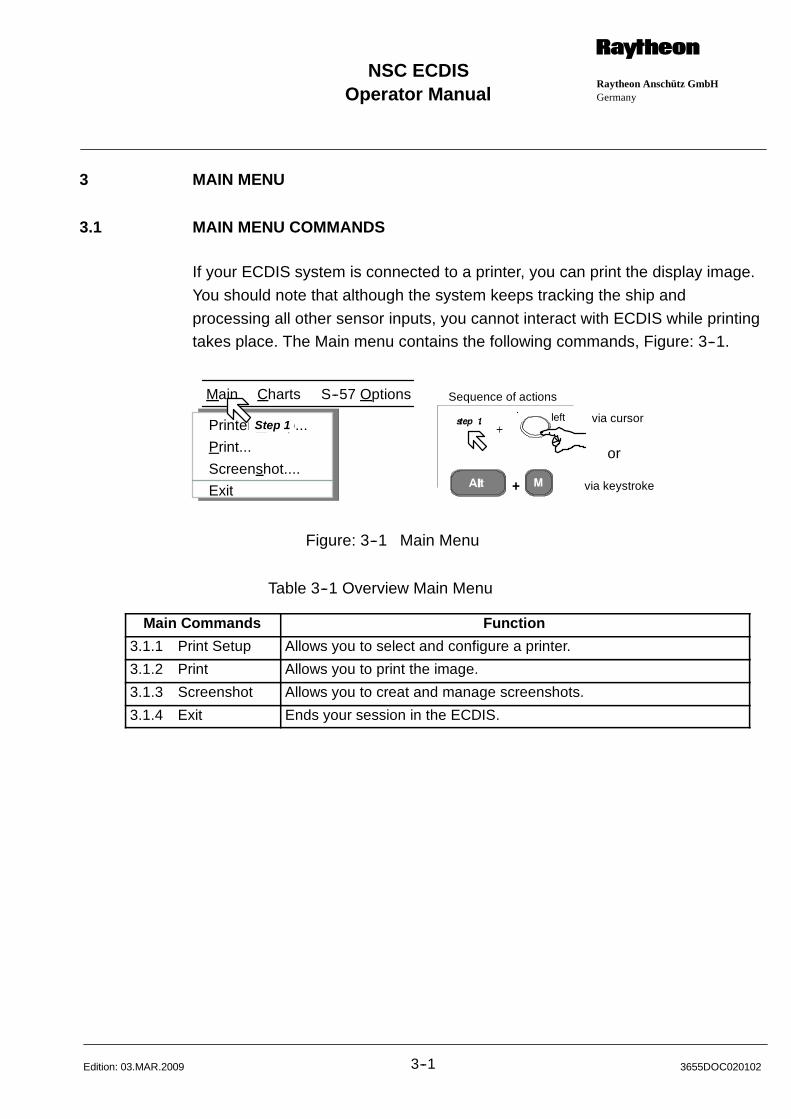
Operator ManualRaytheon Anschütz GmbHGermany
RNSC ECDIS
3--1 3655DOC020102Edition: 03.MAR.2009
3 MAIN MENU
3.1 MAIN MENU COMMANDS
If your ECDIS system is connected to a printer, you can print the display image.
You should note that although the system keeps tracking the ship and
processing all other sensor inputs, you cannot interact with ECDIS while printingtakes place. The Main menu contains the following commands, Figure: 3--1.
via cursor
via keystroke
or
Main Charts S--57 Options
Printer Setup...
Print...
Screenshot....
Exit
Step 1
Sequence of actions
left
Figure: 3--1 Main Menu
Table 3--1 Overview Main Menu
Main Commands Function
3.1.1 Print Setup Allows you to select and configure a printer.
3.1.2 Print Allows you to print the image.
3.1.3 Screenshot Allows you to creat and manage screenshots.
3.1.4 Exit Ends your session in the ECDIS.
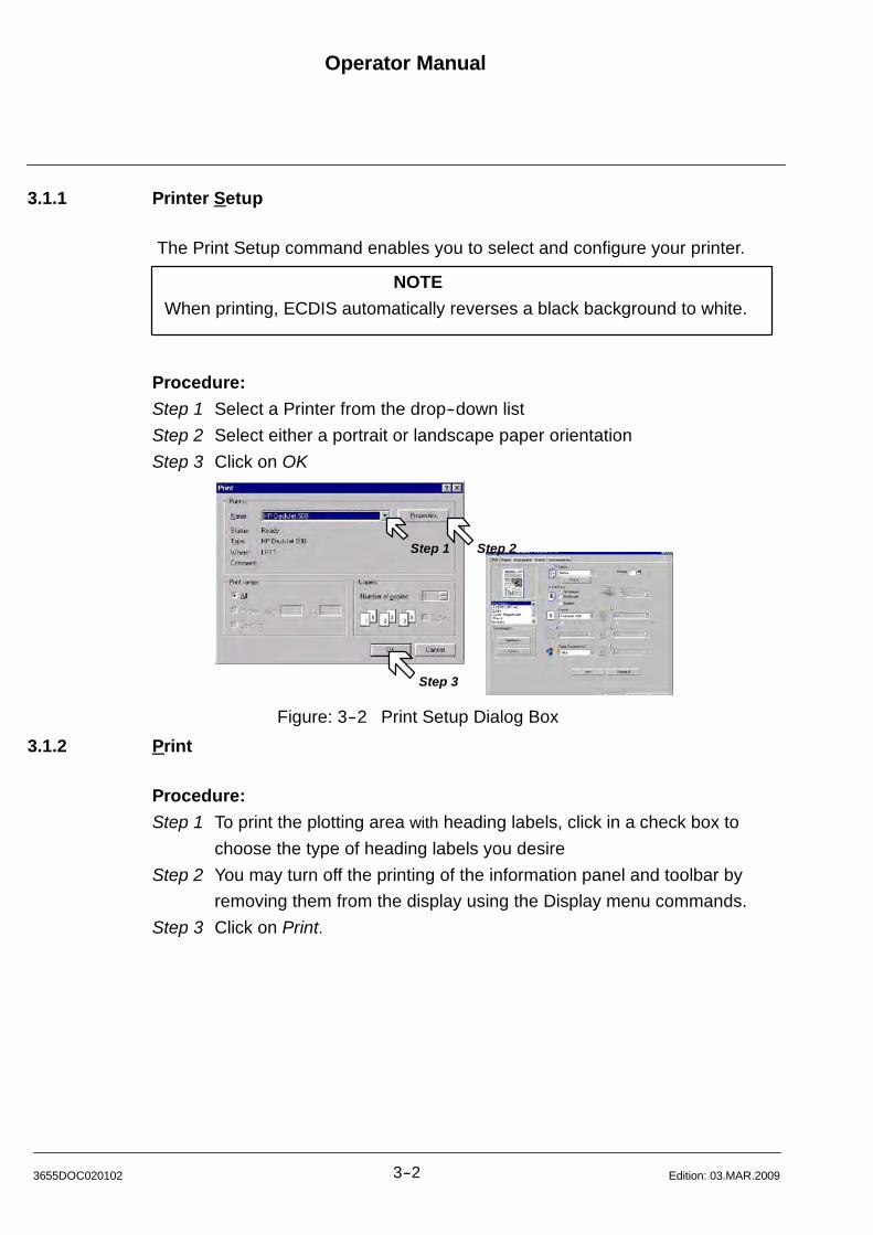
Operator Manual
3--23655DOC020102 Edition: 03.MAR.2009
3.1.1 Printer Setup
The Print Setup command enables you to select and configure your printer.
NOTE
When printing, ECDIS automatically reverses a black background to white.
Procedure:
Step 1 Select a Printer from the drop--down list
Step 2 Select either a portrait or landscape paper orientation
Step 3 Click on OK
Step 1 Step 2
Step 3
Figure: 3--2 Print Setup Dialog Box
3.1.2 Print
Procedure:
Step 1 To print the plotting area with heading labels, click in a check box to
choose the type of heading labels you desire
Step 2 You may turn off the printing of the information panel and toolbar by
removing them from the display using the Display menu commands.
Step 3 Click on Print.
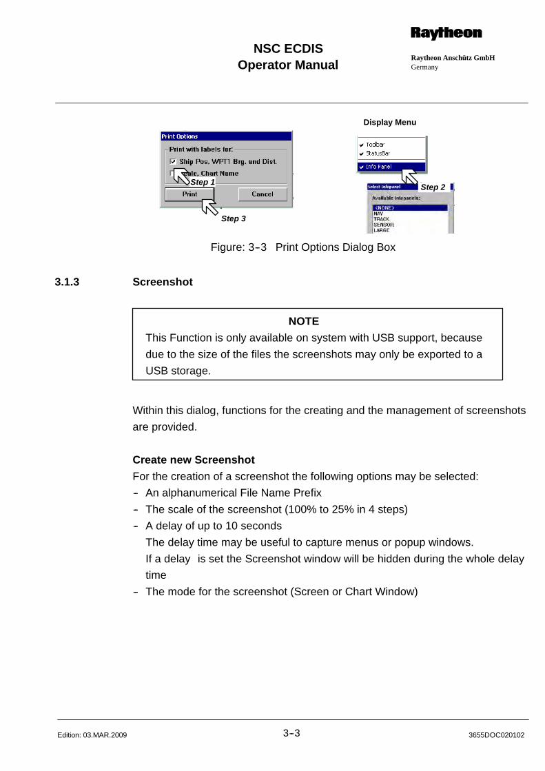
Operator ManualRaytheon Anschütz GmbHGermany
RNSC ECDIS
3--3 3655DOC020102Edition: 03.MAR.2009
Step 1
Step 3
Step 2
Display Menu
Figure: 3--3 Print Options Dialog Box
3.1.3 Screenshot
NOTE
This Function is only available on system with USB support, because
due to the size of the files the screenshots may only be exported to a
USB storage.
Within this dialog, functions for the creating and the management of screenshots
are provided.
Create new Screenshot
For the creation of a screenshot the following options may be selected:
-- An alphanumerical File Name Prefix
-- The scale of the screenshot (100% to 25% in 4 steps)
-- A delay of up to 10 seconds
The delay time may be useful to capture menus or popup windows.
If a delay is set the Screenshot window will be hidden during the whole delay
time
-- The mode for the screenshot (Screen or Chart Window)
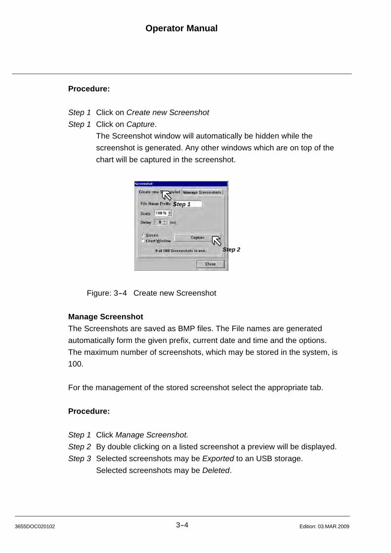
Operator Manual
3--43655DOC020102 Edition: 03.MAR.2009
Procedure:
Step 1 Click on Create new Screenshot
Step 1 Click on Capture.
The Screenshot window will automatically be hidden while the
screenshot is generated. Any other windows which are on top of the
chart will be captured in the screenshot.
Step 2
Step 1
Figure: 3--4 Create new Screenshot
Manage Screenshot
The Screenshots are saved as BMP files. The File names are generated
automatically form the given prefix, current date and time and the options.
The maximum number of screenshots, which may be stored in the system, is
100.
For the management of the stored screenshot select the appropriate tab.
Procedure:
Step 1 Click Manage Screenshot.
Step 2 By double clicking on a listed screenshot a preview will be displayed.
Step 3 Selected screenshots may be Exported to an USB storage.
Selected screenshots may be Deleted.
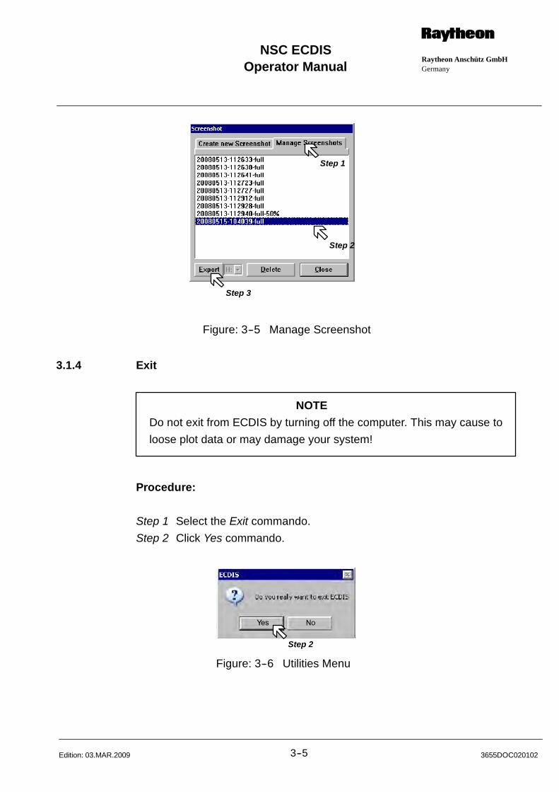
Operator ManualRaytheon Anschütz GmbHGermany
RNSC ECDIS
3--5 3655DOC020102Edition: 03.MAR.2009
Step 2
Step 3
Step 1
Figure: 3--5 Manage Screenshot
3.1.4 Exit
NOTE
Do not exit from ECDIS by turning off the computer. This may cause to
loose plot data or may damage your system!
Procedure:
Step 1 Select the Exit commando.
Step 2 Click Yes commando.
Step 2
Figure: 3--6 Utilities Menu

Operator Manual
3--63655DOC020102 Edition: 03.MAR.2009
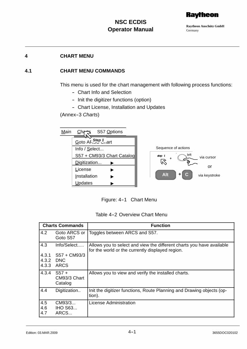
Operator ManualRaytheon Anschütz GmbHGermany
RNSC ECDIS
4--1 3655DOC020102Edition: 03.MAR.2009
4 CHART MENU
4.1 CHART MENU COMMANDS
This menu is used for the chart management with following process functions:
-- Chart Info and Selection
-- Init the digitizer functions (option)
-- Chart License, Installation and Updates
(Annex--3 Charts)
Alt C
via cursor
via keystroke
or
+
Sequence of actions
Main Charts S57 Options
Goto ARSC Chart
Info / Select...
S57 + CM93/3 Chart Catalog
Digitization... "
License "
Installation "
Updates "
Step 1
left
Figure: 4--1 Chart Menu
Table 4--2 Overview Chart Menu
Charts Commands Function
4.2 Goto ARCS orGoto S57
Toggles between ARCS and S57.
4.3 Info/Select.....
4.3.1 S57 + CM93/34.3.2 DNC4.3.3 ARCS
Allows you to select and view the different charts you have availablefor the world or the currently displayed region.
4.3.4 S57 +CM93/3 ChartCatalog
Allows you to view and verify the installed charts.
4.4 Digitization.. Init the digitizer functions, Route Planning and Drawing objects (op-tion).
4.5 CM93/3...4.6 IHO S63...4.7 ARCS...
License Administration
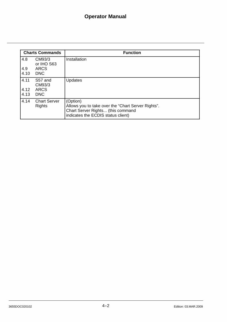
Operator Manual
4--23655DOC020102 Edition: 03.MAR.2009
Charts Commands Function
4.8 CM93/3or IHO S63
4.9 ARCS4.10 DNC
Installation
4.11 S57 andCM93/3
4.12 ARCS4.13 DNC
Updates
4.14 Chart ServerRights
(Option)Allows you to take over the “Chart Server Rights”.Chart Server Rights... (this commandindicates the ECDIS status client)
Operator ManualRaytheon Anschütz GmbHGermany
RNSC ECDIS
4--3 3655DOC020102Edition: 03.MAR.2009
4.2 GOTO ARCS OR GOTO S57
If the two chart types are stored on the ECDIS.
Procedure:
Step 1 Select Goto ARSC Chart or Goto S57 Chart
Result:
The ECDIS switch over to ARCS chart and inversely to S57 chart.
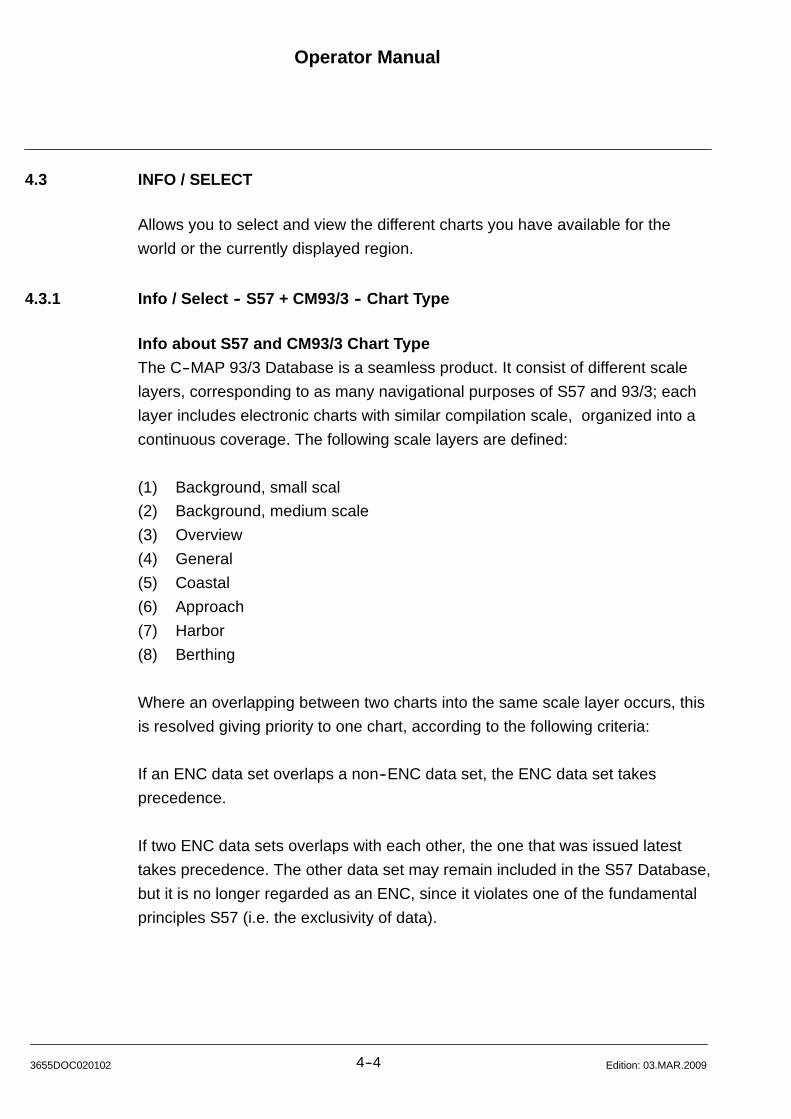
Operator Manual
4--43655DOC020102 Edition: 03.MAR.2009
4.3 INFO / SELECT
Allows you to select and view the different charts you have available for the
world or the currently displayed region.
4.3.1 Info / Select -- S57 + CM93/3 -- Chart Type
Info about S57 and CM93/3 Chart Type
The C--MAP 93/3 Database is a seamless product. It consist of different scale
layers, corresponding to as many navigational purposes of S57 and 93/3; each
layer includes electronic charts with similar compilation scale, organized into a
continuous coverage. The following scale layers are defined:
(1) Background, small scal
(2) Background, medium scale
(3) Overview
(4) General
(5) Coastal
(6) Approach
(7) Harbor
(8) Berthing
Where an overlapping between two charts into the same scale layer occurs, this
is resolved giving priority to one chart, according to the following criteria:
If an ENC data set overlaps a non--ENC data set, the ENC data set takes
precedence.
If two ENC data sets overlaps with each other, the one that was issued latest
takes precedence. The other data set may remain included in the S57 Database,
but it is no longer regarded as an ENC, since it violates one of the fundamental
principles S57 (i.e. the exclusivity of data).

Operator ManualRaytheon Anschütz GmbHGermany
RNSC ECDIS
4--5 3655DOC020102Edition: 03.MAR.2009
Procedure: (Figure: 4--2)
Step 1 Select Charts (menu bar)
Step 2 Select Info / Select... The Dialog Box appears
Step 3 Select S57 + CM93/3
Step 4 Point and click on the different chart types (i.e., Harbor, Coastal, etc.).
In order to see all of your charts, you may need to first click on the World
Chart and click ”View.” Red boxes with hatch marks appears in the
display, and on top of the chart to indicate chart coverage with C--MAP
charts. Official S57 ENCs are marked in green.
Step 5 Point and click on the chart you wish to view (inside the hatched box).
You may need to zoom--in, in order to see the individual charts.
NOTE
You may receive a message which states ”Please center on a region
covered by this chart.” In this case, click on ”OK,” then point and click the
cursor on an area of the chart you wish to view.
Step 6 Click on View to view the chart and leave the dialog box open or
Click on View and Close to view the chart and close the dialog box
NOTE
If the chart you selected does not cover 80 % of the display at the charts
designated scale, the program will override your choice and display a
more appropriate chart. You may override this by zooming in the display
until your chart is displayed.
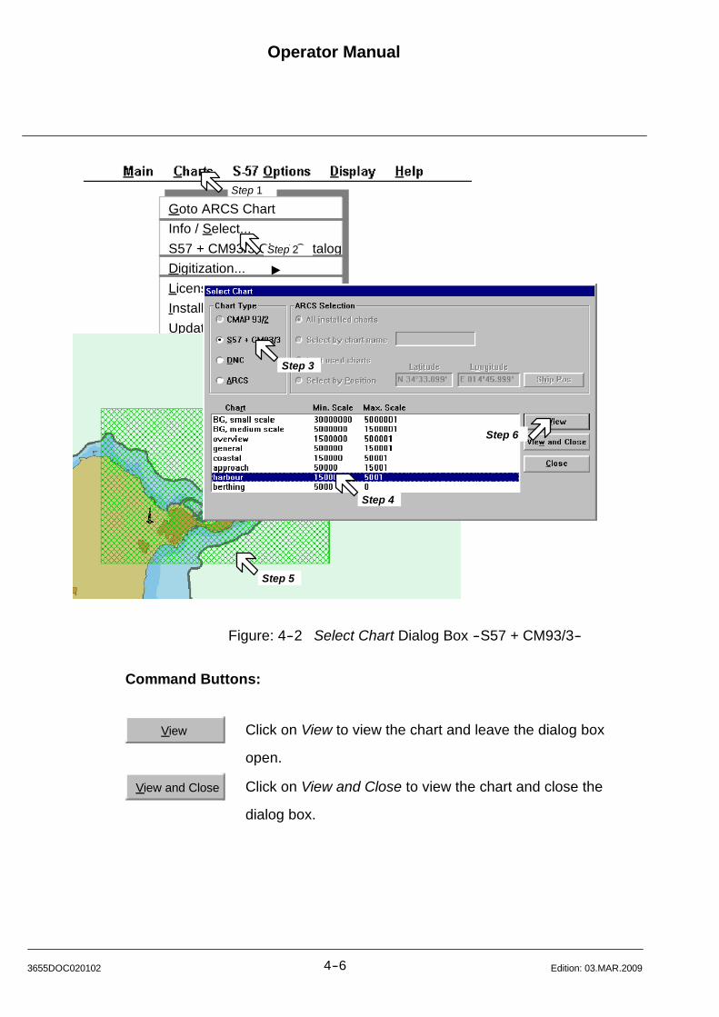
Operator Manual
4--63655DOC020102 Edition: 03.MAR.2009
Goto ARCS Chart
Info / Select...
S57 + CM93/3 Chart Catalog
Digitization... "
License "
Installation "
Updates "
Step 2
Step 3
Step 4
Step 5
Step 6
Step 1
Figure: 4--2 Select Chart Dialog Box --S57 + CM93/3--
Command Buttons:
View Click on View to view the chart and leave the dialog box
open.
View and Close Click on View and Close to view the chart and close the
dialog box.
Operator ManualRaytheon Anschütz GmbHGermany
RNSC ECDIS
4--7 3655DOC020102Edition: 03.MAR.2009
4.3.2 Info / Select -- DNC -- Chart Type
Info about DNC Chart Type
The DNC Database is a seamless product. It consist of different scale layers,
corresponding to as many navigational purposes of DNC; each layer includes
electronic charts with similar compilation scale, organized into a continuous
coverage.
The following scale layers are defined:
(1) Overview
(2) General
(3) Coastal
(4) Harbor
(5) Berthing
Procedure:
Step 1 Select Charts (menu bar)
Step 2 Select Info / Select... The Dialog Box appears
Step 3 Select DNC
Step 4 Point and click on the different chart types (i.e., Harbor, Coastal, etc.).
In order to see all of your charts, you may need to first click on the World
Chart and click ”View.” Red boxes with hatch marks appears in the
display, and on top of the chart. These are your charts.
Step 5 Point and click on the chart you wish to view (inside the hatched box).
You may need to zoom--in, in order to see the individual charts.
NOTE
You may receive a message which states ”Please center on a region
covered by this chart.” In this case, click on ”OK,” then point and click the
cursor on an area of the chart you wish to view.
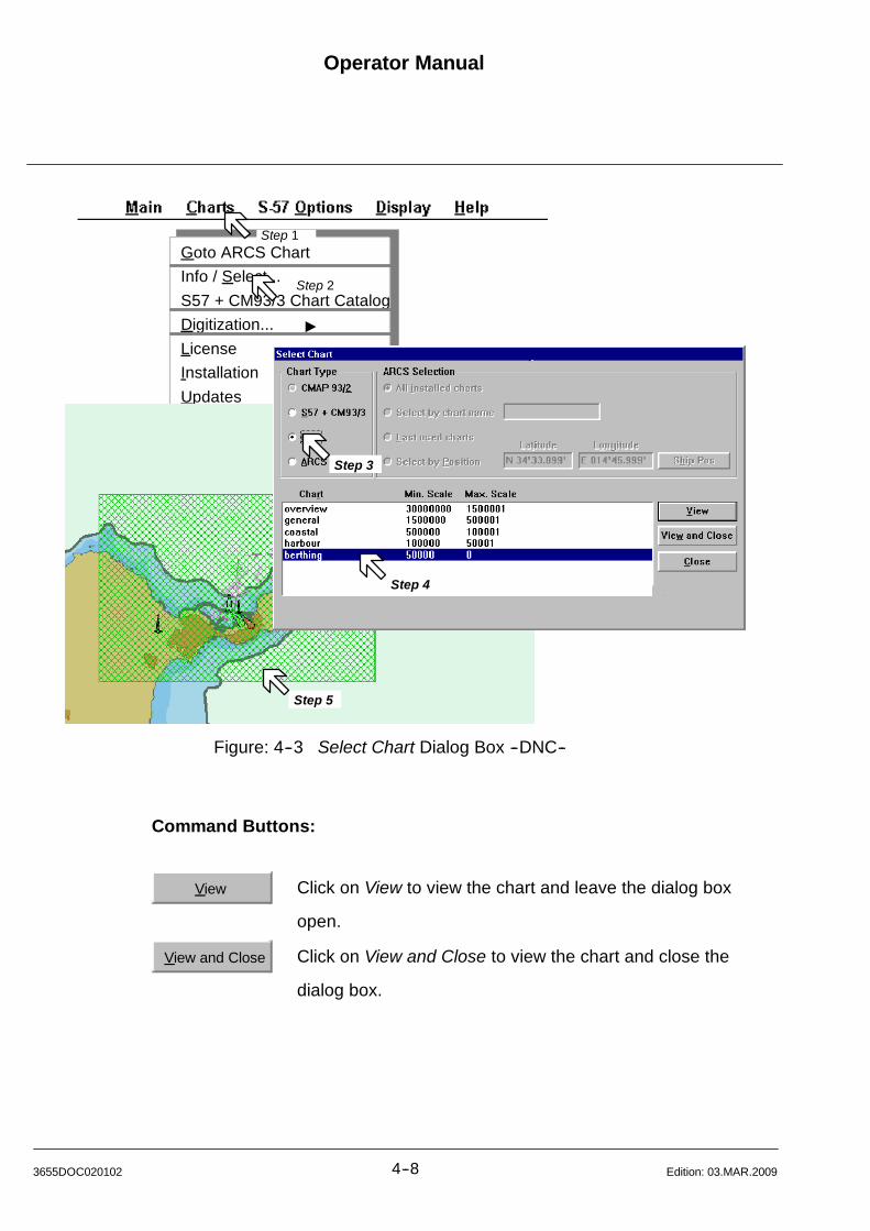
Operator Manual
4--83655DOC020102 Edition: 03.MAR.2009
Goto ARCS Chart
Info / Select...
S57 + CM93/3 Chart Catalog
Digitization... "
License "
Installation "
Updates "
Step 2
Step 5
Step 1
Step 3
Step 4
Figure: 4--3 Select Chart Dialog Box --DNC--
Command Buttons:
View Click on View to view the chart and leave the dialog box
open.
View and Close Click on View and Close to view the chart and close the
dialog box.
Operator ManualRaytheon Anschütz GmbHGermany
RNSC ECDIS
4--9 3655DOC020102Edition: 03.MAR.2009
4.3.3 Info / Select -- ARCS -- Chart Type
Info about ARCS Chart Type
ARCS means Admiralty Raster Chart Service. This institution scans seacharts of
the British Admiralty (BA) in a raster--data--format. Such a manner scanned
seacharts are available on CD--ROM as Raster Nautical Charts (RNCs) with a
worldwide coverage.
A periodical update--service of the ARCS --seacharts is ensured by the
manufacturer.
A seachart in raster--data--format is divided into pixels and then stored.
On the screen of the ECDIS these pixels will be displayed.
In this way the complete (paper--) chart equivalent is displayed on the screen.
As additional information only the geographically coordinates are displayed (after
selection by courser) on the Information Panel.
Other, for seacharts typically information, as there are buoys, light beacons,
wrecks or depth information can only be read out of the displayed seachart.
There is no object query possible on Raster charts.
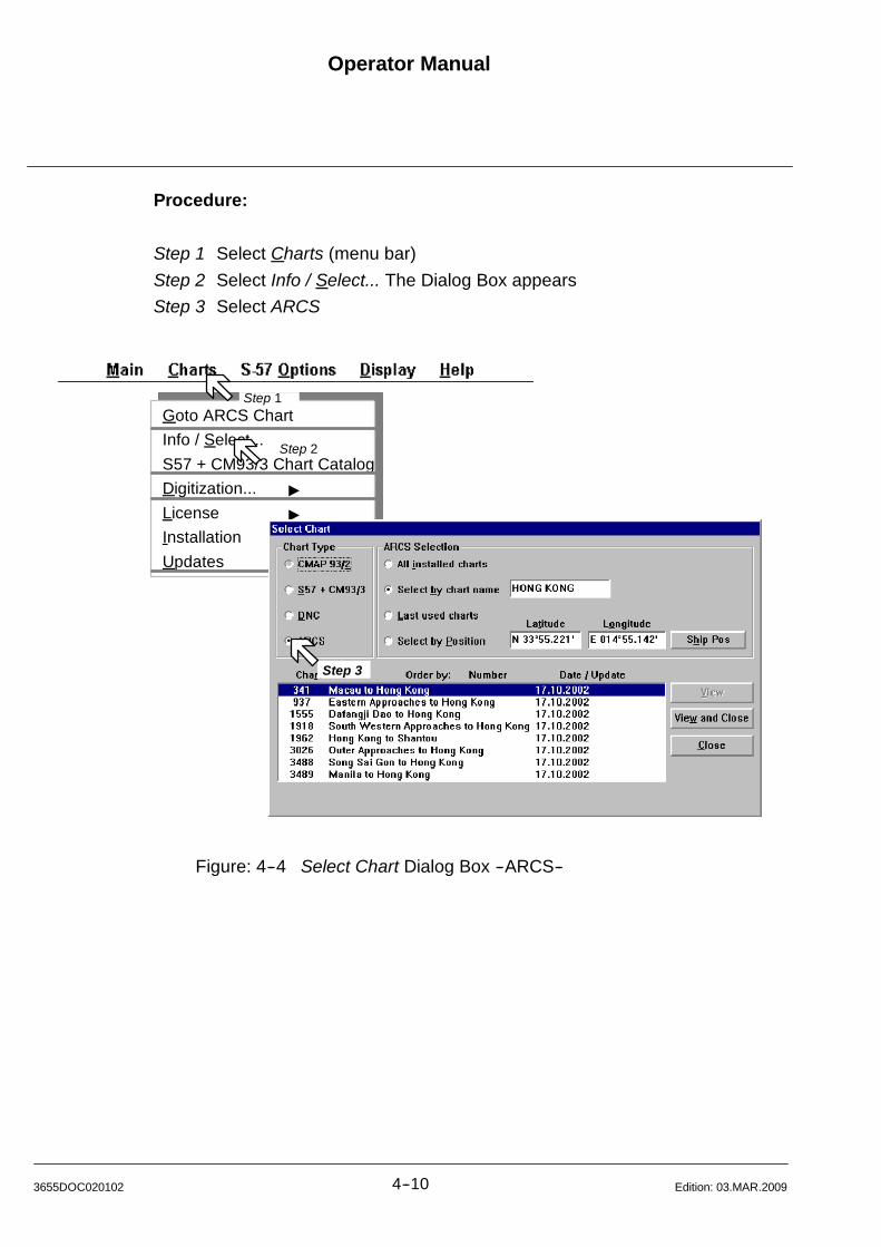
Operator Manual
4--103655DOC020102 Edition: 03.MAR.2009
Procedure:
Step 1 Select Charts (menu bar)
Step 2 Select Info / Select... The Dialog Box appears
Step 3 Select ARCS
Goto ARCS Chart
Info / Select...
S57 + CM93/3 Chart Catalog
Digitization... "
License "
Installation "
Updates "
Step 2
Step 1
Step 3
Figure: 4--4 Select Chart Dialog Box --ARCS--
All installed charts
Select by chartname
Last used charts
Select by Position
Operator ManualRaytheon Anschütz GmbHGermany
RNSC ECDIS
4--11 3655DOC020102Edition: 03.MAR.2009
ARCS Selection:
S Shows all installed charts in the List Box
S Select chart by name.
Example: Type--in the name of selected sea--area, for example “oslo”.
In the List Box all ARCS charts already installed having
“oslo” including in their name are listed in the box..
Set a double click onto the respective chart.
S The last used charts listed in the box.
S Select by Position.
In this case position coordinates (longitude/latitude) can be input either
manually or directly by cursor positioning.
Manual Inputs:
Editing the requested coordinates respective seachart will be loaded
and displayed.
Click on “View and Close” button.
By Cursor Position:
Set the cursor on this sea--area for which the ARCS chart is to be loaded.
Click on “View and Close” button.
The selected chart is loaded and displayed.
By Ship Position:
Click on the “Ship Pos” button.
The respective ARCS chart (according to ship position) will be loaded.
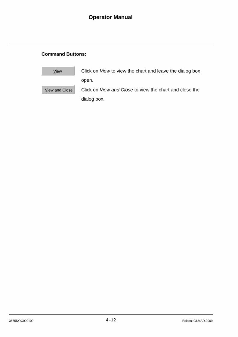
Operator Manual
4--123655DOC020102 Edition: 03.MAR.2009
Command Buttons:
View Click on View to view the chart and leave the dialog box
open.
View and Close Click on View and Close to view the chart and close the
dialog box.
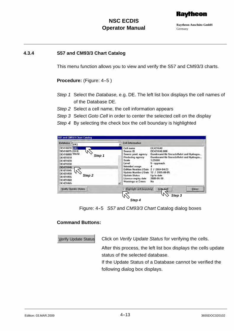
Operator ManualRaytheon Anschütz GmbHGermany
RNSC ECDIS
4--13 3655DOC020102Edition: 03.MAR.2009
4.3.4 S57 and CM93/3 Chart Catalog
This menu function allows you to view and verify the S57 and CM93/3 charts.
Procedure: (Figure: 4--5 )
Step 1 Select the Database, e.g. DE. The left list box displays the cell names of
of the Database DE.
Step 2 Select a cell name, the cell information appears
Step 3 Select Goto Cell in order to center the selected cell on the display
Step 4 By selecting the check box the cell boundary is highlighted
Step 1
Step 2
Step 4Step 3
Figure: 4--5 S57 and CM93/3 Chart Catalog dialog boxes
Command Buttons:
Verify Update Status Click on Verify Update Status for verifying the cells.
After this process, the left list box displays the cells update
status of the selected database.
If the Update Status of a Database cannot be verified the
following dialog box displays.
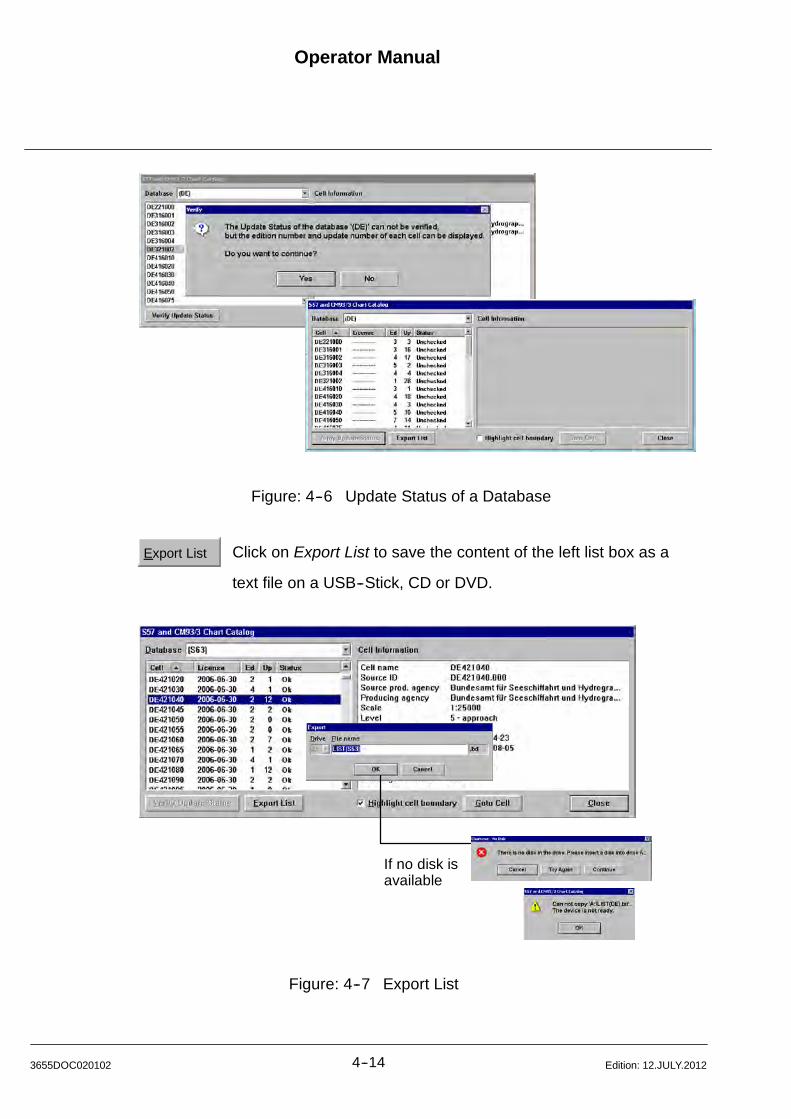
Operator Manual
4--143655DOC020102 Edition: 12.JULY.2012
Figure: 4--6 Update Status of a Database
Export List Click on Export List to save the content of the left list box as a
text file on a USB--Stick, CD or DVD.
If no disk isavailable
Figure: 4--7 Export List
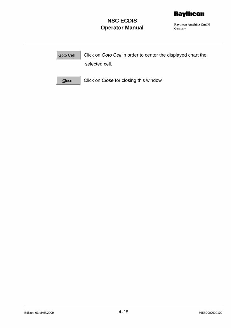
Operator ManualRaytheon Anschütz GmbHGermany
RNSC ECDIS
4--15 3655DOC020102Edition: 03.MAR.2009
Goto Cell Click on Goto Cell in order to center the displayed chart the
selected cell.
Close Click on Close for closing this window.
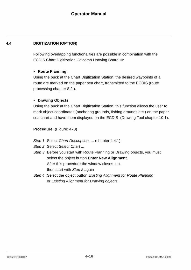
Operator Manual
4--163655DOC020102 Edition: 03.MAR.2009
4.4 DIGITIZATION (OPTION)
Following overlapping functionalities are possible in combination with the
ECDIS Chart Digitization Calcomp Drawing Board III:
Route Planning
Using the puck at the Chart Digitization Station, the desired waypoints of a
route are marked on the paper sea chart, transmitted to the ECDIS (route
processing chapter 8.2.).
Drawing Objects
Using the puck at the Chart Digitization Station, this function allows the user to
mark object coordinates (anchoring grounds, fishing grounds etc.) on the paper
sea chart and have them displayed on the ECDIS (Drawing Tool chapter 10.1).
Procedure: (Figure: 4--8)
Step 1 Select Chart Description .... (chapter 4.4.1)
Step 2 Select Select Chart ...
Step 3 Before you start with Route Planning or Drawing objects, you must
select the object button Enter New Alignment.
After this procedure the window closes--up.
then start with Step 2 again
Step 4 Select the object button Existing Alignment for Route Planning
or Existing Alignment for Drawing objects.
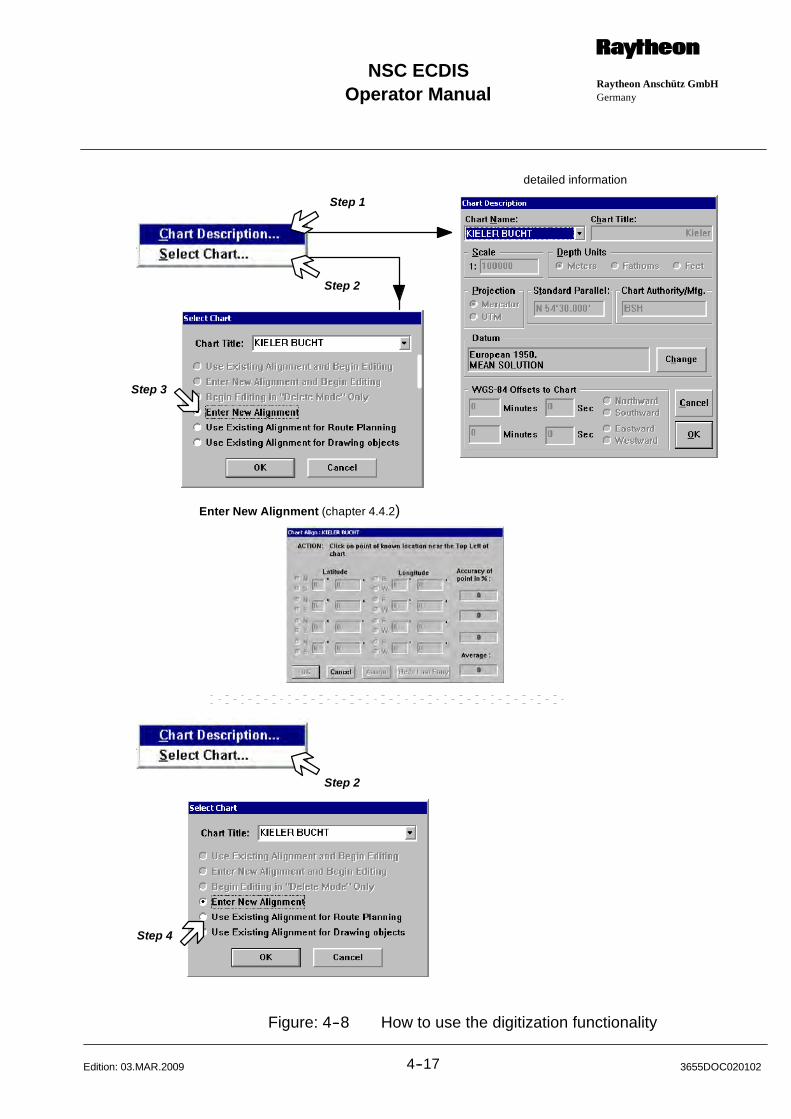
Operator ManualRaytheon Anschütz GmbHGermany
RNSC ECDIS
4--17 3655DOC020102Edition: 03.MAR.2009
Enter New Alignment (chapter 4.4.2)
Step 1
Step 2
Step 3
Step 2
Step 4
detailed information
Figure: 4--8 How to use the digitization functionality
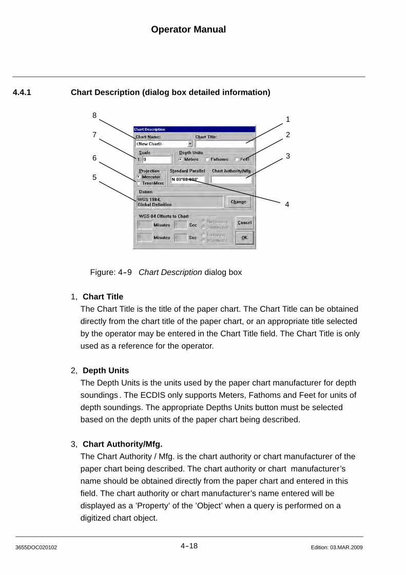
Operator Manual
4--183655DOC020102 Edition: 03.MAR.2009
4.4.1 Chart Description (dialog box detailed information)
1
2
3
4
5
6
7
8
Figure: 4--9 Chart Description dialog box
1, Chart Title
The Chart Title is the title of the paper chart. The Chart Title can be obtained
directly from the chart title of the paper chart, or an appropriate title selected
by the operator may be entered in the Chart Title field. The Chart Title is only
used as a reference for the operator.
2, Depth Units
The Depth Units is the units used by the paper chart manufacturer for depth
soundings . The ECDIS only supports Meters, Fathoms and Feet for units of
depth soundings. The appropriate Depths Units button must be selected
based on the depth units of the paper chart being described.
3, Chart Authority/Mfg.
The Chart Authority / Mfg. is the chart authority or chart manufacturer of the
paper chart being described. The chart authority or chart manufacturer’s
name should be obtained directly from the paper chart and entered in this
field. The chart authority or chart manufacturer’s name entered will be
displayed as a ’Property’ of the ’Object’ when a query is performed on a
digitized chart object.
Operator ManualRaytheon Anschütz GmbHGermany
RNSC ECDIS
4--19 3655DOC020102Edition: 03.MAR.2009
4, Standard Parallel / Standard Meridian
Based on the projection method selected, either the Standard Parallel or the
Standard Meridian label will be displayed next to the input box for appropriate
latitude or longitude respectfully.
The Standard Parallel is the latitude that the paper chart manufacturer has
selected as the center parallel for purposes of projection. The latitude entered
for the Standard Parallel field must be obtained directly from the paper chart
being described.
The Standard Meridian is the longitude that the paper chart manufacturer
has selected as the center meridian for purpose of projection. The longitude
entered for Standard Meridian field must be obtained directly from the paper
chart being described.
5, Datum
The Datum is the horizontal reference datum that was used for the creation of
the paper chart. The ECDIS support all datums in IHO S--60. The Datum
selected must be obtained directly from the paper chart being described. If the
datum of the paper chart is not available in the list of ECDIS supported
datums, then Non should be selected for the datum, and an offset entered as
described in section WGS--84 Offsets to Chart.
6, Projection
Projection is the projection method used by the chart authority or chart
manufacturer during the creation of the paper chart. The ECDIS only supports
Mercator and Universal Transverse Mercator (TransMerc) projection methods
for purposes of chart digitization. The appropriate Projection button must be
selected based on the projection method used to create the paper chart being
described.
7, Scale
The Select field contains the scale of the paper chart being described. The
value entered in this field must be taken directly from the paper chart. The
scale value entered will be displayed as ’Property’ of the Object when a query
is performed on a digitized chart object.
Operator Manual
4--203655DOC020102 Edition: 03.MAR.2009
8, Chart Name
The Chart Name is the actual file name that the chart description information
is saved in. The Chart Name field contains a pull--down list containing one
option called <untitled> and a list of any previously saved chart description is
being entered for the first time. Once the chart description process has been
successfully completed, the chart file name entered by the operator will
displayed in the pull--down list.
Previously saved chart files can be recalled by selecting the chart name in the
pull--down list. When a previously saved chart file is selected, all of remaining
fields in the dialog box are filled in with the previously saved information and
no other operator action is required.
WGS--84 Offsets to Chart
The WSG--84 Offset to Chart are the offset values used when the paper chart
being described has been created with a datum other than one of the datum
in the pull--down datum list. If the paper chart being described was created
with a datum other than one of the listed datum, and an offset to WGS--84
datum is provided on the paper chart, then an offset can be entered.
The WSG--84 Offset to Chart field is only available when the selected Datum
is None. These WSG--84 Offset to Chart values must be obtained directly
from the paper chart being described. The offset values represented on the
paper chart may be in minutes, fractions of minutes, seconds, fractions of
seconds, or combination of minutes and seconds. The offset values obtained
from the paper chart should be entered into the WSG--84 Offset to Chart
fields just as they appear on the paper chart. The following table provides
examples of valid entries in the WSG--84 Offset to Chart fields based on
offsets taken from various paper charts.
WGS--84 Offsets Fields
Offset on Paper Chart Minutes Seconds Button
0.02 Minutes Northward 0.02 N
0.1 Minutes Eastward 0.1 E
0.736” Southward 0.736 S
4.819” Westward 4.819 W
The offset values entered will be displayed as a ’Property’ of the ’Object’ when a
query is performed on a digitized chart object.
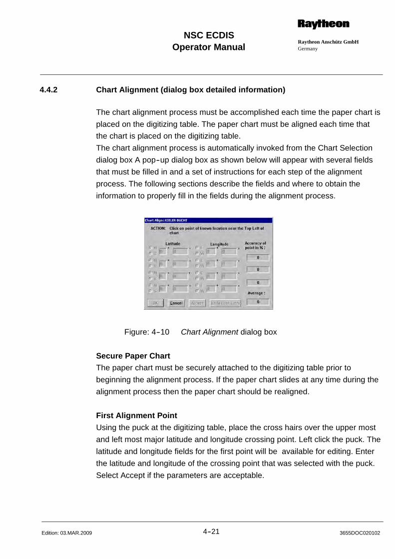
Operator ManualRaytheon Anschütz GmbHGermany
RNSC ECDIS
4--21 3655DOC020102Edition: 03.MAR.2009
4.4.2 Chart Alignment (dialog box detailed information)
The chart alignment process must be accomplished each time the paper chart is
placed on the digitizing table. The paper chart must be aligned each time that
the chart is placed on the digitizing table.
The chart alignment process is automatically invoked from the Chart Selection
dialog box A pop--up dialog box as shown below will appear with several fields
that must be filled in and a set of instructions for each step of the alignment
process. The following sections describe the fields and where to obtain the
information to properly fill in the fields during the alignment process.
Figure: 4--10 Chart Alignment dialog box
Secure Paper ChartThe paper chart must be securely attached to the digitizing table prior to
beginning the alignment process. If the paper chart slides at any time during the
alignment process then the paper chart should be realigned.
First Alignment Point
Using the puck at the digitizing table, place the cross hairs over the upper most
and left most major latitude and longitude crossing point. Left click the puck. The
latitude and longitude fields for the first point will be available for editing. Enter
the latitude and longitude of the crossing point that was selected with the puck.
Select Accept if the parameters are acceptable.
Operator Manual
4--223655DOC020102 Edition: 03.MAR.2009
Second Alignment Point
Using the puck at the digitizing table, place the cross hairs over the lower most
and left most major latitude and longitude crossing point. The longitude of this
second alignment point must be the same longitude as the first alignment point.
Left click the puck. Only the latitude field of the second point will be available for
editing. The longitude field of the second point will be automatically entered.
Enter the latitude of the crossing point that was selected with the puck. Select
Accept if the parameters are acceptable.
A value representing the percentage of accuracy will be automatically calculated
and entered in the right--hand column, this value is indicative of paper chart
stretch or shrinkage, data entry correctness and physical chart alignment on the
table.
Third Alignment Point
Using the puck at the digitizing table, place the cross hairs over the lower most
and right most majors latitude and longitude crossing point. The latitude of this
third alignment point must be the same latitude as the second crossing point.
Left click the puck. Only the longitude of the third point will be available for
editing. The latitude field of the third point will be automatically entered. Enter the
longitude of crossing point that was selected with the puck. Select Accept if the
parameters are acceptable. Again, a value representing the percentage of
accuracy will be automatically calculated and entered in the right--hand column.
Fourth Alignment Point
Using the puck at the digitizing table, place the cross hairs over any know point
on the chart. Left click the puck. The latitude and the longitude field for the fourth
alignment point will be available for editing. Enter the latitude and longitude of
the point that was selected with the puck. Select Accept if the parameters are
acceptable. The percentage accuracy for the final point will be calculated and an
average of all the accuracy is determined, if the average percentage accuracy
does not fall within pre--specified limits, the chart alignment must be repeated.
Refer to the next paragraph for further details.
Operator ManualRaytheon Anschütz GmbHGermany
RNSC ECDIS
4--23 3655DOC020102Edition: 03.MAR.2009
4.5 LICENSE ADMINISTRATION FOR CM93/3 LICENSES
(see Annex--6 Charts S57 License)
CM93/3 Description93/3 licences for 93/3 charts are obtained from C--MAP Norway AS and are
available for Worldwide Coverage, one or more Zones, one or more Areas,
or single charts.
Licenses can only be used on the system for which they were generated and
cannot be transferred to other software or hardware systems. Licenses can be
added manually or automatically. To add a license manually simply choose the
data set or area name on the right side of this box and type the corresponding
license string into the appropriate box.
The user has the option of subscribing to or purchasing licenses:
In case of subscription, licenses are valid for 12 months from the moment in
which they are registered in the system (see below). The subscription fee
includes the update service performed through the CM93/3 Distribution
Center, plus two issues of the CD--ROM, that will be sent to the user after four
and eight months.
Subscriptions are automatically renewed and invoiced after the first year and
every subsequent year; C--MAP must be notified in writing of subscription
termination, at least three months before the renewal date.
In case of purchase, licenses are valid on a permanent basis (i.e. they never
expire). Updating is not included.
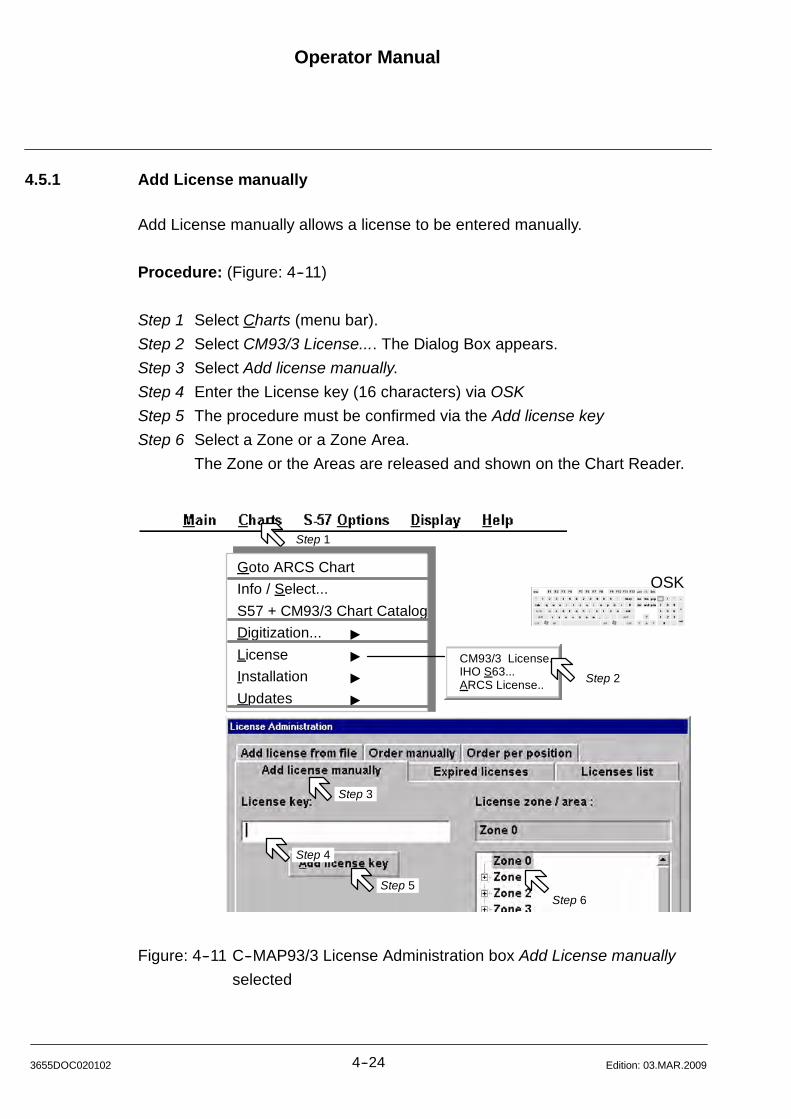
Operator Manual
4--243655DOC020102 Edition: 03.MAR.2009
4.5.1 Add License manually
Add License manually allows a license to be entered manually.
Procedure: (Figure: 4--11)
Step 1 Select Charts (menu bar).
Step 2 Select CM93/3 License.... The Dialog Box appears.
Step 3 Select Add license manually.
Step 4 Enter the License key (16 characters) via OSK
Step 5 The procedure must be confirmed via the Add license key
Step 6 Select a Zone or a Zone Area.
The Zone or the Areas are released and shown on the Chart Reader.
Step 1
Step 3
Step 4
Step 6Step 5
OSKGoto ARCS Chart
Info / Select...
S57 + CM93/3 Chart Catalog
Digitization... "
License "
Installation "
Updates "
CM93/3 License..IHO S63...ARCS License.. Step 2
Figure: 4--11 C--MAP93/3 License Administration box Add License manually
selected
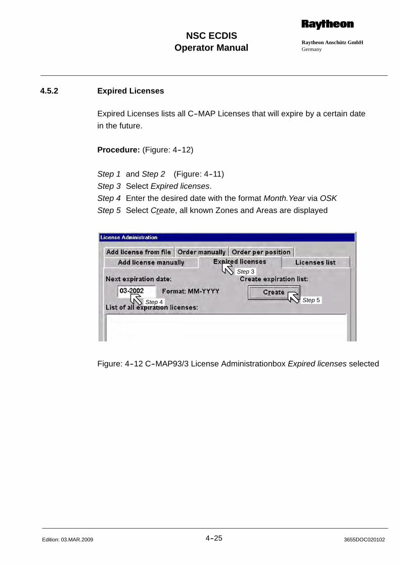
Operator ManualRaytheon Anschütz GmbHGermany
RNSC ECDIS
4--25 3655DOC020102Edition: 03.MAR.2009
4.5.2 Expired Licenses
Expired Licenses lists all C--MAP Licenses that will expire by a certain date
in the future.
Procedure: (Figure: 4--12)
Step 1 and Step 2 (Figure: 4--11)
Step 3 Select Expired licenses.
Step 4 Enter the desired date with the format Month.Year via OSK
Step 5 Select Create, all known Zones and Areas are displayed
Step 3
Step 4 Step 5
Step 3
Step 4 Step 5
Figure: 4--12 C--MAP93/3 License Administrationbox Expired licenses selected
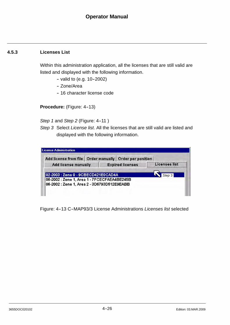
Operator Manual
4--263655DOC020102 Edition: 03.MAR.2009
4.5.3 Licenses List
Within this administration application, all the licenses that are still valid are
listed and displayed with the following information.
-- valid to (e.g. 10--2002)
-- Zone/Area
-- 16 character license code
Procedure: (Figure: 4--13)
Step 1 and Step 2 (Figure: 4--11 )
Step 3 Select License list. All the licenses that are still valid are listed and
displayed with the following information.
Step 3
Figure: 4--13 C--MAP93/3 License Administrations Licenses list selected
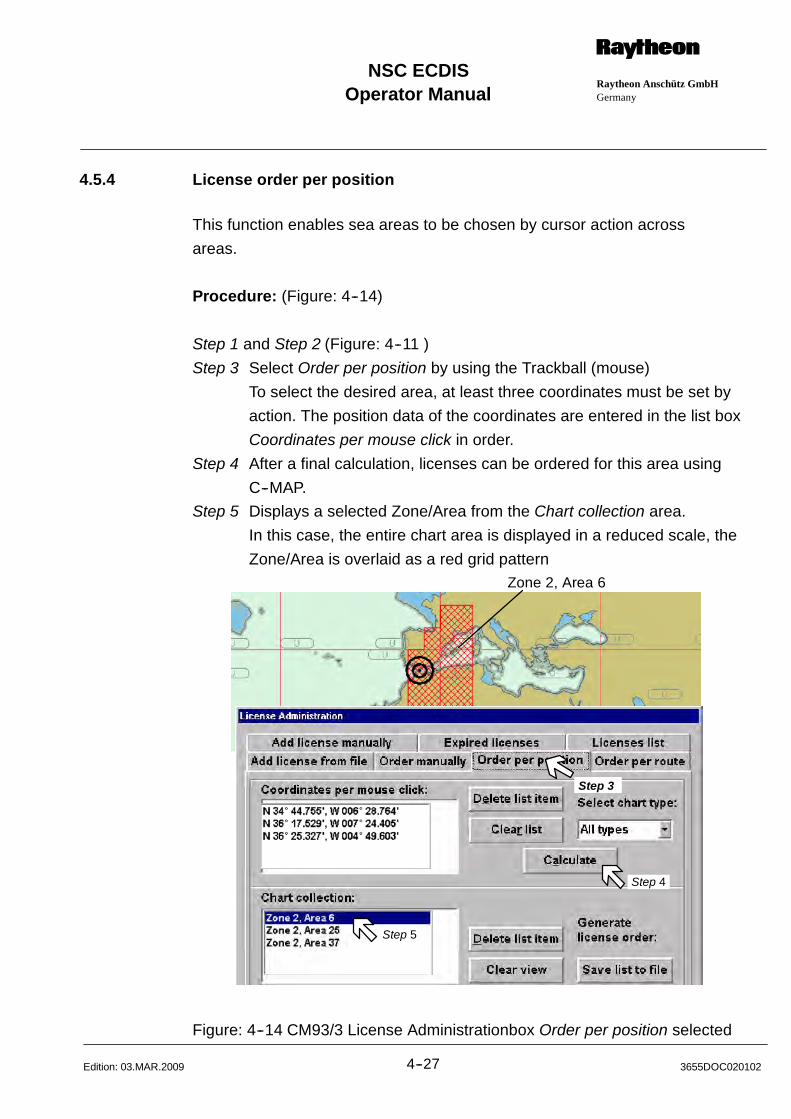
Operator ManualRaytheon Anschütz GmbHGermany
RNSC ECDIS
4--27 3655DOC020102Edition: 03.MAR.2009
4.5.4 License order per position
This function enables sea areas to be chosen by cursor action across
areas.
Procedure: (Figure: 4--14)
Step 1 and Step 2 (Figure: 4--11 )
Step 3 Select Order per position by using the Trackball (mouse)
To select the desired area, at least three coordinates must be set by
action. The position data of the coordinates are entered in the list box
Coordinates per mouse click in order.
Step 4 After a final calculation, licenses can be ordered for this area using
C--MAP.
Step 5 Displays a selected Zone/Area from the Chart collection area.
In this case, the entire chart area is displayed in a reduced scale, the
Zone/Area is overlaid as a red grid pattern
Step 3
Step 4
Step 5
Zone 2, Area 6
Figure: 4--14 CM93/3 License Administrationbox Order per position selected
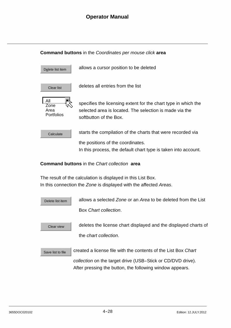
AllZoneAreaPortfolios
Operator Manual
4--283655DOC020102 Edition: 12.JULY.2012
Command buttons in the Coordinates per mouse click area
Delete list item allows a cursor position to be deleted
Clear list deletes all entries from the list
specifies the licensing extent for the chart type in which the
selected area is located. The selection is made via the
softbutton of the Box.
Calculate starts the compilation of the charts that were recorded via
the positions of the coordinates.
In this process, the default chart type is taken into account.
Command buttons in the Chart collection area
The result of the calculation is displayed in this List Box.
In this connection the Zone is displayed with the affected Areas.
Delete list item allows a selected Zone or an Area to be deleted from the List
Box Chart collection.
Clear view deletes the license chart displayed and the displayed charts of
the chart collection.
Save list to file created a license file with the contents of the List Box Chart
collection on the target drive (USB--Stick or CD/DVD drive).
After pressing the button, the following window appears.
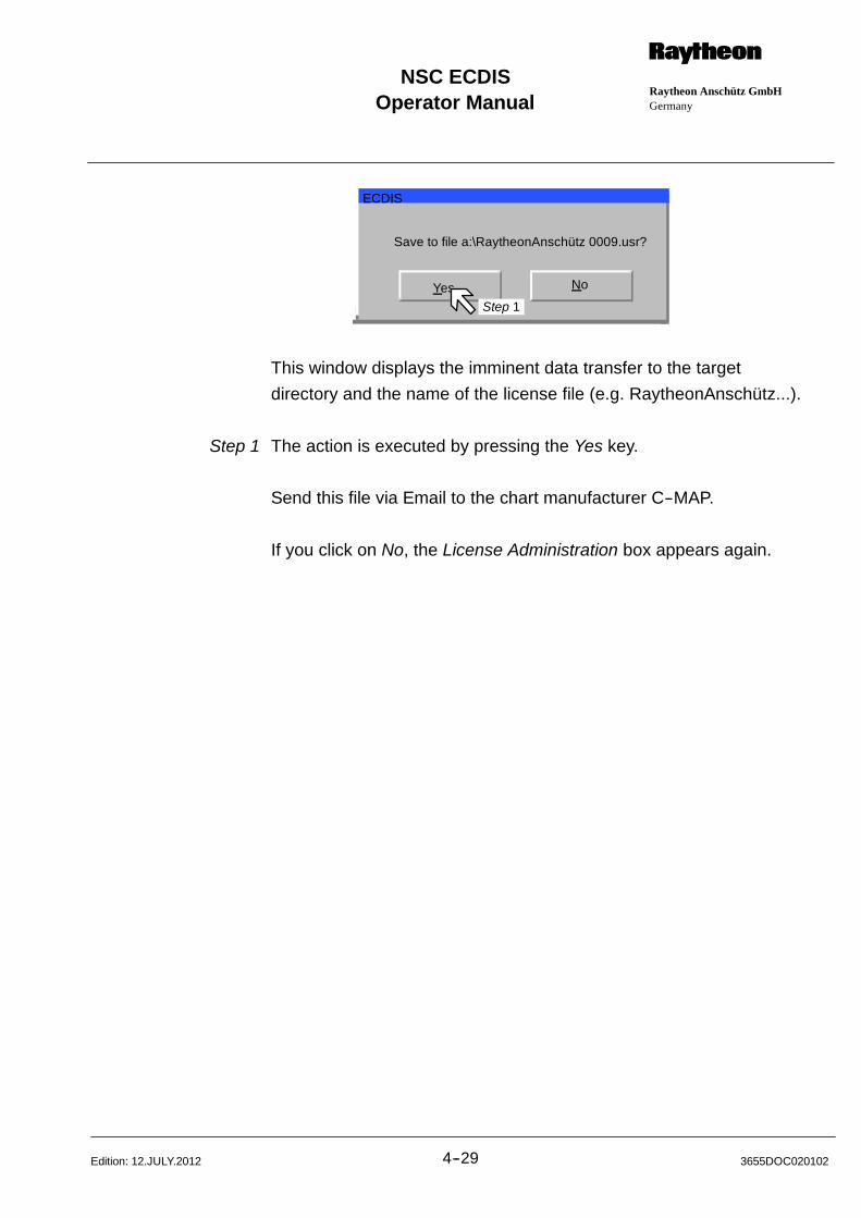
Operator ManualRaytheon Anschütz GmbHGermany
RNSC ECDIS
4--29 3655DOC020102Edition: 12.JULY.2012
Save to file a:\RaytheonAnschütz 0009.usr?
Yes No
ECDIS
Step 1
This window displays the imminent data transfer to the target
directory and the name of the license file (e.g. RaytheonAnschütz...).
Step 1 The action is executed by pressing the Yes key.
Send this file via Email to the chart manufacturer C--MAP.
If you click on No, the License Administration box appears again.
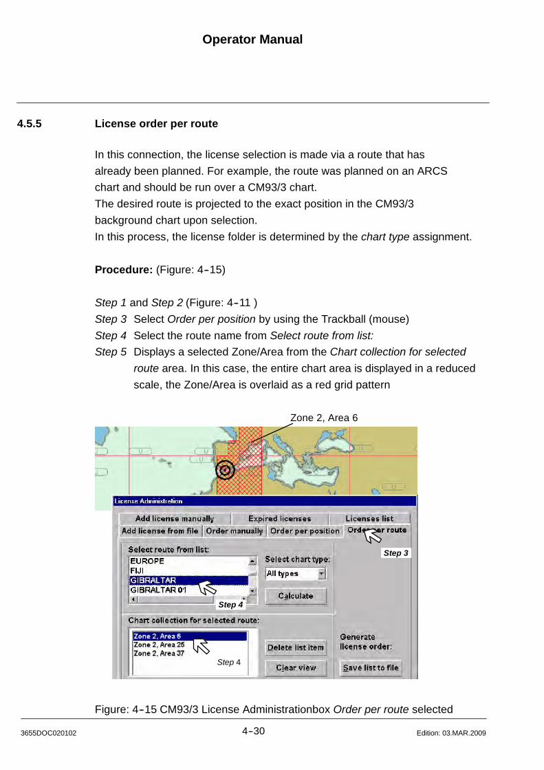
Operator Manual
4--303655DOC020102 Edition: 03.MAR.2009
4.5.5 License order per route
In this connection, the license selection is made via a route that has
already been planned. For example, the route was planned on an ARCS
chart and should be run over a CM93/3 chart.
The desired route is projected to the exact position in the CM93/3
background chart upon selection.
In this process, the license folder is determined by the chart type assignment.
Procedure: (Figure: 4--15)
Step 1 and Step 2 (Figure: 4--11 )
Step 3 Select Order per position by using the Trackball (mouse)
Step 4 Select the route name from Select route from list:
Step 5 Displays a selected Zone/Area from the Chart collection for selected
route area. In this case, the entire chart area is displayed in a reduced
scale, the Zone/Area is overlaid as a red grid pattern
Step 4
Step 4
Zone 2, Area 6
Step 3
Figure: 4--15 CM93/3 License Administrationbox Order per route selected
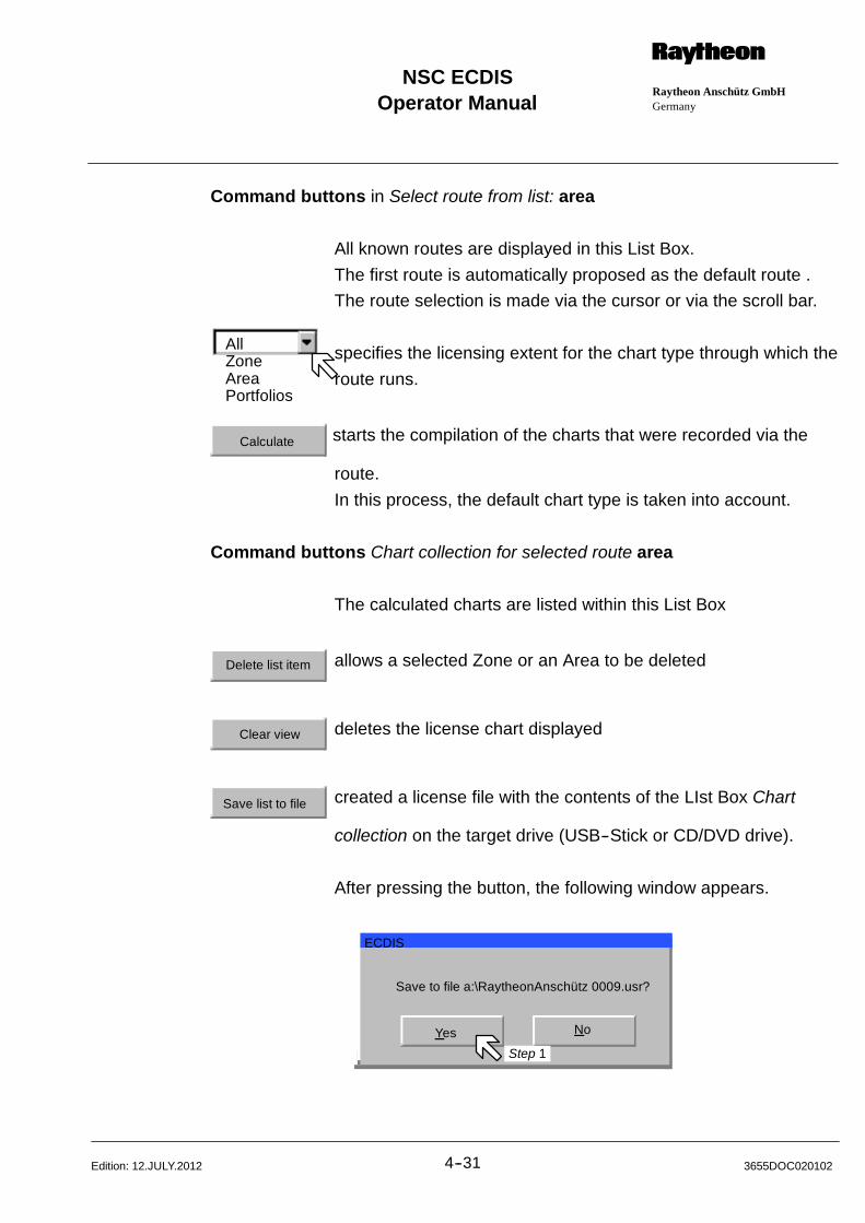
AllZoneAreaPortfolios
Operator ManualRaytheon Anschütz GmbHGermany
RNSC ECDIS
4--31 3655DOC020102Edition: 12.JULY.2012
Command buttons in Select route from list: area
All known routes are displayed in this List Box.
The first route is automatically proposed as the default route .
The route selection is made via the cursor or via the scroll bar.
specifies the licensing extent for the chart type through which the
route runs.
Calculate starts the compilation of the charts that were recorded via the
route.
In this process, the default chart type is taken into account.
Command buttons Chart collection for selected route area
The calculated charts are listed within this List Box
Delete list item allows a selected Zone or an Area to be deleted
Clear view deletes the license chart displayed
Save list to file created a license file with the contents of the LIst Box Chart
collection on the target drive (USB--Stick or CD/DVD drive).
After pressing the button, the following window appears.
Save to file a:\RaytheonAnschütz 0009.usr?
Yes No
ECDIS
Step 1
Operator Manual
4--323655DOC020102 Edition: 03.MAR.2009
This window displays the imminent file transfer to the target directory and the
name of the license file (e.g. Raytheon Anschütz...).
Step 1 The action is executed by pressing the Yes key.
Send this file via Email to the chart manufacturer C--MAP.
If you click on No, the License Administration box appears again.
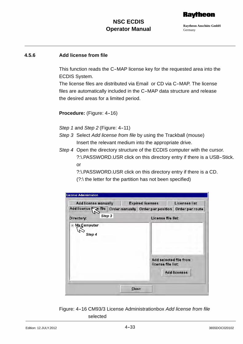
Operator ManualRaytheon Anschütz GmbHGermany
RNSC ECDIS
4--33 3655DOC020102Edition: 12.JULY.2012
4.5.6 Add license from file
This function reads the C--MAP license key for the requested area into the
ECDIS System.
The license files are distributed via Email or CD via C--MAP. The license
files are automatically included in the C--MAP data structure and release
the desired areas for a limited period.
Procedure: (Figure: 4--16)
Step 1 and Step 2 (Figure: 4--11)
Step 3 Select Add license from file by using the Trackball (mouse)
Insert the relevant medium into the appropriate drive.
Step 4 Open the directory structure of the ECDIS computer with the cursor.
?:\.PASSWORD.USR click on this directory entry if there is a USB--Stick.
or
?:\.PASSWORD.USR click on this directory entry if there is a CD.
(?:\ the letter for the partition has not been specified)
Step 1
Step 4
Step 3
Figure: 4--16 CM93/3 License Administrationbox Add license from file
selected

Operator Manual
4--343655DOC020102 Edition: 03.MAR.2009
Command button
Add licenses Within the List Box License file list: all licenses are overlaid when
the key is pressed. At the same time, the licenses are processed
within the program.
The desired areas are released.
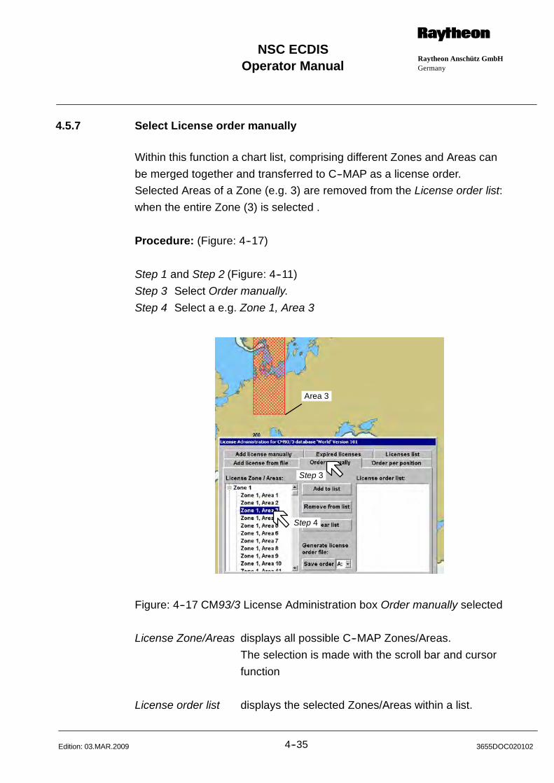
Operator ManualRaytheon Anschütz GmbHGermany
RNSC ECDIS
4--35 3655DOC020102Edition: 03.MAR.2009
4.5.7 Select License order manually
Within this function a chart list, comprising different Zones and Areas can
be merged together and transferred to C--MAP as a license order.
Selected Areas of a Zone (e.g. 3) are removed from the License order list:
when the entire Zone (3) is selected .
Procedure: (Figure: 4--17)
Step 1 and Step 2 (Figure: 4--11)
Step 3 Select Order manually.
Step 4 Select a e.g. Zone 1, Area 3
Step 3
Step 4
Area 3
Figure: 4--17 CM93/3 License Administration box Order manually selected
License Zone/Areas displays all possible C--MAP Zones/Areas.
The selection is made with the scroll bar and cursor
function
License order list displays the selected Zones/Areas within a list.

Operator Manual
4--363655DOC020102 Edition: 12.JULY.2012
Command button
Add to list inserts the selected Zone/Areas from the List Box.
Action can also be executed by clicking the desired Zones/Areas
with the cursor.
Remove from list deletes the selected names from the List Box
deletes all entries from the List Box in sequence.
Clear list deletes all entries from the List Box
Create creates a license file from the List Box
The following window appears when the key is pressed.
Yes NoStep 1
Step 1 The action is executed via Yes.
Send this file via Email to the chart manufacturer C--MAP.
If you click on No, the “License Administration” box appears again.
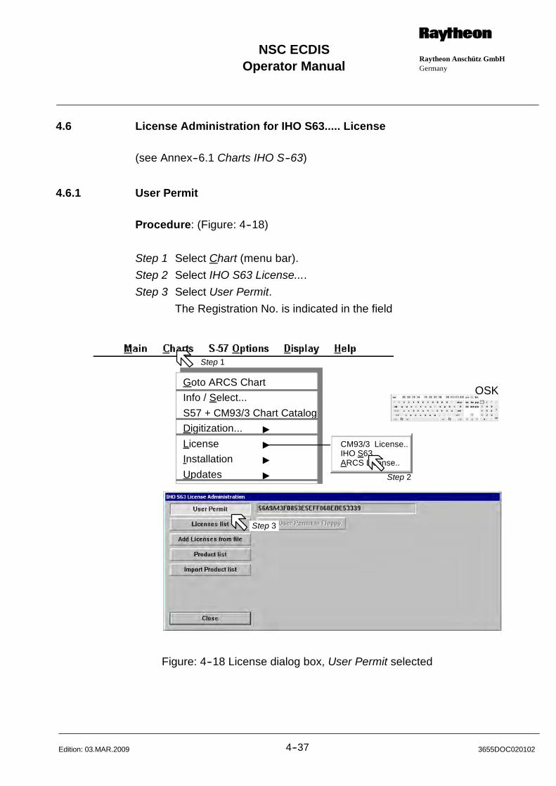
Operator ManualRaytheon Anschütz GmbHGermany
RNSC ECDIS
4--37 3655DOC020102Edition: 03.MAR.2009
4.6 License Administration for IHO S63..... License
(see Annex--6.1 Charts IHO S--63)
4.6.1 User Permit
Procedure: (Figure: 4--18)
Step 1 Select Chart (menu bar).
Step 2 Select IHO S63 License....
Step 3 Select User Permit.
The Registration No. is indicated in the field
Step 1
Step 3
Goto ARCS Chart
Info / Select...
S57 + CM93/3 Chart Catalog
Digitization... "
License "
Installation "
Updates "
OSK
CM93/3 License..IHO S63...ARCS License..
Step 2
Figure: 4--18 License dialog box, User Permit selected

Operator Manual
4--383655DOC020102 Edition: 03.MAR.2009
4.6.2 Licenses list
Procedure: (Figure: 4--19)
Step 1 and Step 2 (Figure: 4--18)
Step 3 Select Licenses list.
Licenses can be renewed and the status of the current license list
reviewed
Step 3
Status information
Step 3
Figure: 4--19 License dialog box, Licenses list selected
Command Buttons:
Delete selected License Delete the selected Cell License
Delete expired License Delete the expired Cell License
Delete all Licenses Delete all Cell Licenses
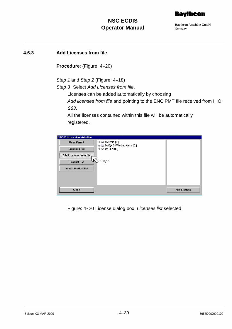
Operator ManualRaytheon Anschütz GmbHGermany
RNSC ECDIS
4--39 3655DOC020102Edition: 03.MAR.2009
4.6.3 Add Licenses from file
Procedure: (Figure: 4--20)
Step 1 and Step 2 (Figure: 4--18)
Step 3 Select Add Licenses from file.
Licenses can be added automatically by choosing
Add licenses from file and pointing to the ENC.PMT file received from IHO
S63.
All the licenses contained within this file will be automatically
registered.
Step 3
Figure: 4--20 License dialog box, Licenses list selected
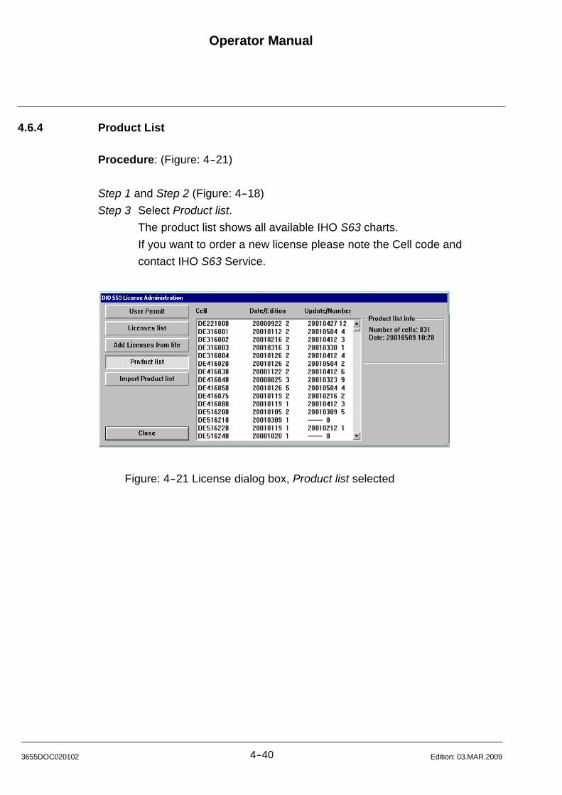
Operator Manual
4--403655DOC020102 Edition: 03.MAR.2009
4.6.4 Product List
Procedure: (Figure: 4--21)
Step 1 and Step 2 (Figure: 4--18)
Step 3 Select Product list.
The product list shows all available IHO S63 charts.
If you want to order a new license please note the Cell code and
contact IHO S63 Service.
Step 3
Figure: 4--21 License dialog box, Product list selected

Operator ManualRaytheon Anschütz GmbHGermany
RNSC ECDIS
4--41 3655DOC020102Edition: 12.JULY.2012
4.6.5 Import Product list
If you got a CD or data set via Email with updates or new chart cells IHO S63
include a second data file with a new product list .
Procedure: (Figure: 4--22)
Step 1 and Step 2 (Figure: 4--18)
Step 3 Select Import Product list.
The new product list overwrites the old one.
(The old product list cannot be rewritten from an older CD version)
Step 3
Figure: 4--22 License dialog box, “Import Product list” selected

Operator Manual
4--423655DOC020102 Edition: 03.MAR.2009
4.7 LICENSE ADMINISTRATION FOR ARCS LICENSE
Procedure: (Figure: 4--23)
Step 1 Select Chart (menu bar).
Step 2 Select ARCS License....
Step 3 If you have no Security Key (software dongle) loaded before the
License Administrator dialog box appears at first. Follow the text items in
the dialog box.
Step 4 Start the identification check.
Step 1
Step 3
Goto ARCS Chart
Info / Select...
S57 + CM93/3 Chart Catalog
Digitization... "
License "
Installation "
Updates "
OSK
CM93/3 License..IHO S63...ARCS License..
Step 2
Step 4
Figure: 4--23 ARCS Permit List dialog box selected
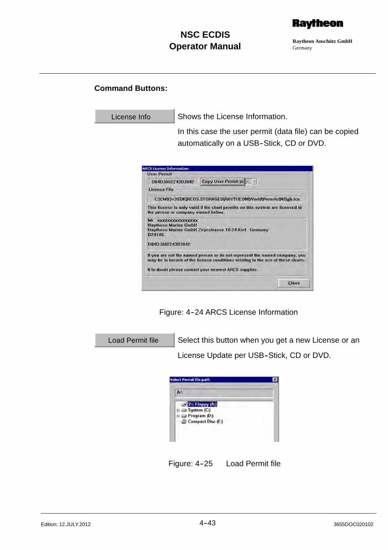
Operator ManualRaytheon Anschütz GmbHGermany
RNSC ECDIS
4--43 3655DOC020102Edition: 12.JULY.2012
Command Buttons:
License Info Shows the License Information.
In this case the user permit (data file) can be copied
automatically on a USB--Stick, CD or DVD.
Figure: 4--24 ARCS License Information
Load Permit file Select this button when you get a new License or an
License Update per USB--Stick, CD or DVD.
Figure: 4--25 Load Permit file
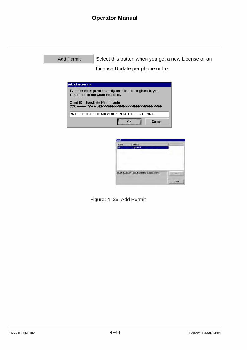
Operator Manual
4--443655DOC020102 Edition: 03.MAR.2009
Add Permit Select this button when you get a new License or an
License Update per phone or fax.
Figure: 4--26 Add Permit

Operator ManualRaytheon Anschütz GmbHGermany
RNSC ECDIS
4--45 3655DOC020102Edition: 03.MAR.2009
Remove Permit Select the relevant chart before and click on the Remove
Permit button.
Practice: If you got a license update, sometime a chart
permit cancelled and replaced by another chart
number.
Read SCHEDULE A AMENDMENT--CHART SUPPLY
DETAILS from the ADMIRALTY RASTER CHART
SERVICE.
Figure: 4--27 Remove Permit
Remove All Select this function to remove all charts.
Figure: 4--28 Remove All

Operator Manual
4--463655DOC020102 Edition: 03.MAR.2009
4.8 CM93/3 or IHO S63 Installation....
(see Annex 6.2 and 6.3 Installation S57 ... ARCS)
The electronic charts belonging to the two most general “navigational purposes”
(i.e. the so--called background charts) are stored on the C--MAP 93/3 Database
CD--ROM in non--encrypted form, meaning that can be freely accessed and
displayed on the ECDIS, before the user actually buys licenses for the charts.
All other charts are stored on the CD--ROM in encrypted in S57 format, meaning
that the user has to buy licenses to access and display them.
Each license corresponding to one electronic chart.
Procedure: (Figure: 4--29)
Step 1 Select Charts (menu bar)
Step 2 Select Installation
Step 3 Select S57 and CM93/3 Installation
Step 4 Select Install CM93/3 Database
To install a database, place CD into the CD drive and press the Install
Database button. The installation will be take 3 to 5 minutes.
If no CD is available a dialog box appears, follow the text item or Cancel
this function.
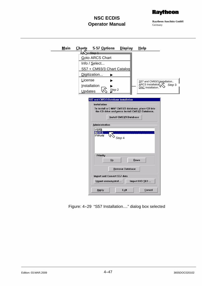
Operator ManualRaytheon Anschütz GmbHGermany
RNSC ECDIS
4--47 3655DOC020102Edition: 03.MAR.2009
S57 and CM93/3 Installation..ARCS Installation..DNC Installation..
Goto ARCS Chart
Info / Select...
S57 + CM93/3 Chart Catalog
Digitization... "
License "
Installation "
Updates "
Step 1
Step 4
Step 2
Step 3
Figure: 4--29 “S57 Installation....” dialog box selected

(S63)World
n
n
(GB)n
Operator Manual
4--483655DOC020102 Edition: 03.MAR.2009
Install Database The process by which the user chooses which chart he
wants to access (i.e. which licenses he needs to buy) is
called Install Database.
To install a database, place CD into the CD drive and
press the Install Database button.
The installation will be take 3 to 5 minutes.
If no CD is available a dialog box appears, follow the text
item or Cancel this function.
Dialog Box Area:
Administration
In the Administration area you can see available
charts.
The “n” symbol indicates the selected charts.
Dialog Box Area:
Priority
Up Down If you want to modify the layer priority, select the chart
you will have displayed first or last and click Priority
“Up” or “Down”.
Remove Database To remove a selected database, click on
“Remove Database”.
Before the program deletes the selected database a
dialog box appears with the question Are you sure......
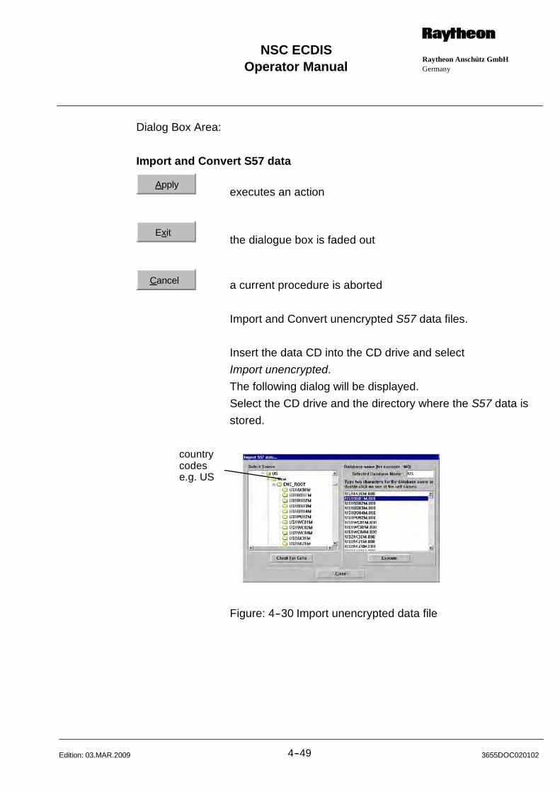
Operator ManualRaytheon Anschütz GmbHGermany
RNSC ECDIS
4--49 3655DOC020102Edition: 03.MAR.2009
Dialog Box Area:
Import and Convert S57 data
Applyexecutes an action
Exitthe dialogue box is faded out
Cancel a current procedure is aborted
Import and Convert unencrypted S57 data files.
Insert the data CD into the CD drive and select
Import unencrypted.
The following dialog will be displayed.
Select the CD drive and the directory where the S57 data is
stored.
countrycodese.g. US
Figure: 4--30 Import unencrypted data file
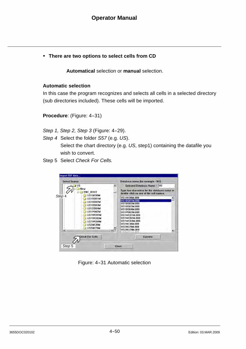
Operator Manual
4--503655DOC020102 Edition: 03.MAR.2009
There are two options to select cells from CD
Automatical selection or manual selection.
Automatic selection
In this case the program recognizes and selects all cells in a selected directory
(sub directories included). These cells will be imported.
Procedure: (Figure: 4--31)
Step 1, Step 2, Step 3 (Figure: 4--29).
Step 4 Select the folder S57 (e.g. US).
Select the chart directory (e.g. US, step1) containing the datafile you
wish to convert.
Step 5 Select Check For Cells.
Step 4
Step 5
Figure: 4--31 Automatic selection
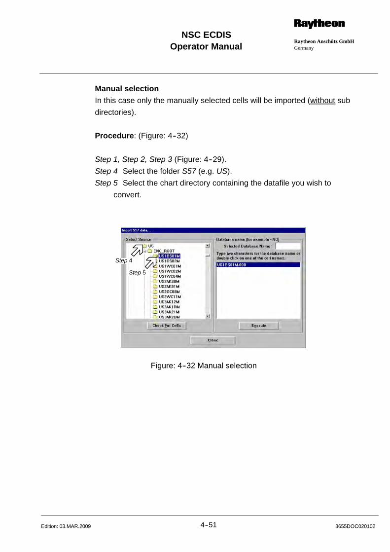
Operator ManualRaytheon Anschütz GmbHGermany
RNSC ECDIS
4--51 3655DOC020102Edition: 03.MAR.2009
Manual selection
In this case only the manually selected cells will be imported (without sub
directories).
Procedure: (Figure: 4--32)
Step 1, Step 2, Step 3 (Figure: 4--29).
Step 4 Select the folder S57 (e.g. US).
Step 5 Select the chart directory containing the datafile you wish to
convert.
Step 4
Step 5
Figure: 4--32 Manual selection
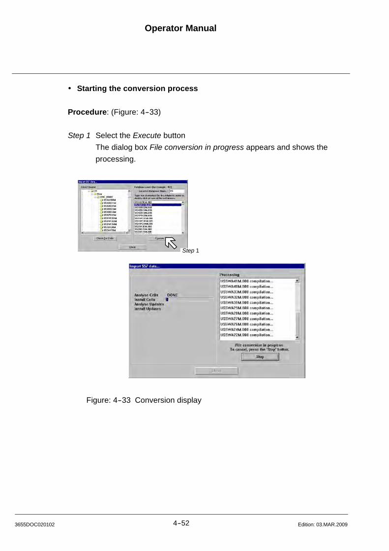
Operator Manual
4--523655DOC020102 Edition: 03.MAR.2009
Starting the conversion process
Procedure: (Figure: 4--33)
Step 1 Select the Execute button
The dialog box File conversion in progress appears and shows the
processing.
Step 1
Figure: 4--33 Conversion display

Operator ManualRaytheon Anschütz GmbHGermany
RNSC ECDIS
4--53 3655DOC020102Edition: 03.MAR.2009
The conversion process ends with following dialog box (Figure: 4--34).
Step 1 Select OK.
Step 1
Step 2
Figure: 4--34 Import of data completed
If you want to see the complete installation information,
then select View Log (Step 2). The following dialog window appears.
NoteIf the following message appears:
Following cells were not installed:XXXXXXXXXX
That means:The chart is invalid, contact thechart manufacturer and state to thecell identifier.
For a detailed error informationabout a cell in the summary list,please select the cell (step1).
Step 2
Figure: 4--35 Compilation log dialog box
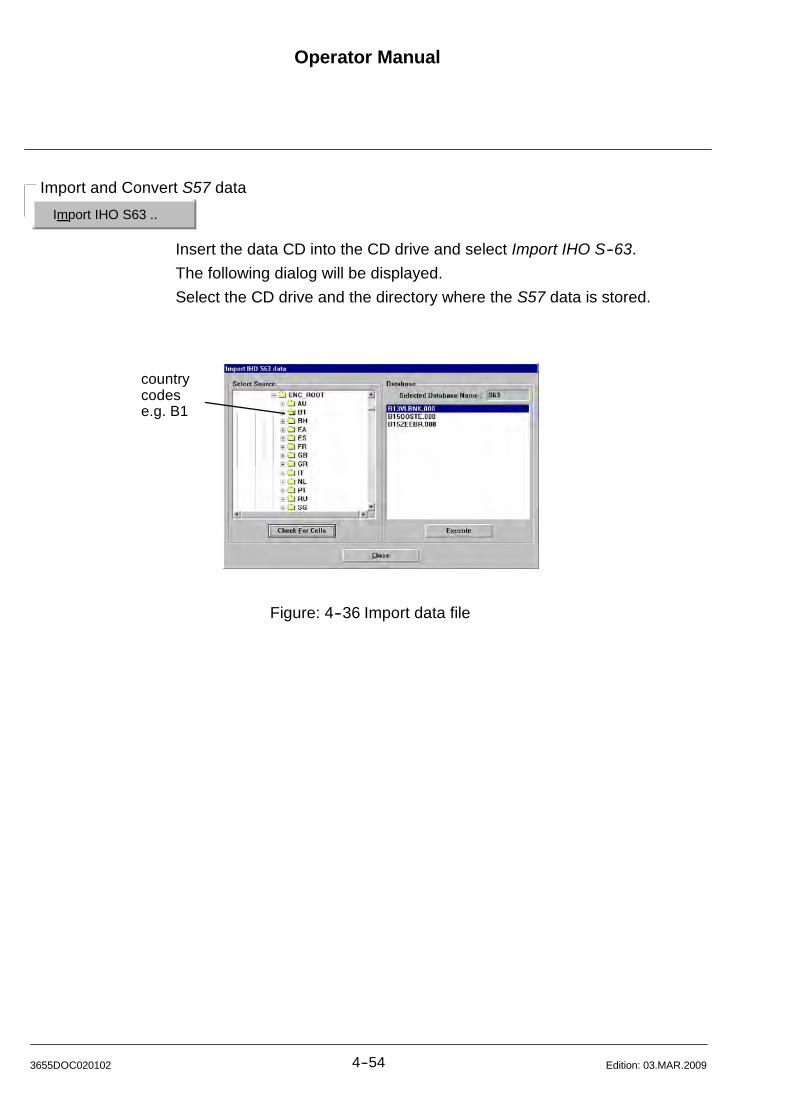
Import IHO S63 ..
Import and Convert S57 data
Operator Manual
4--543655DOC020102 Edition: 03.MAR.2009
Insert the data CD into the CD drive and select Import IHO S--63.
The following dialog will be displayed.
Select the CD drive and the directory where the S57 data is stored.
countrycodese.g. B1
Figure: 4--36 Import data file
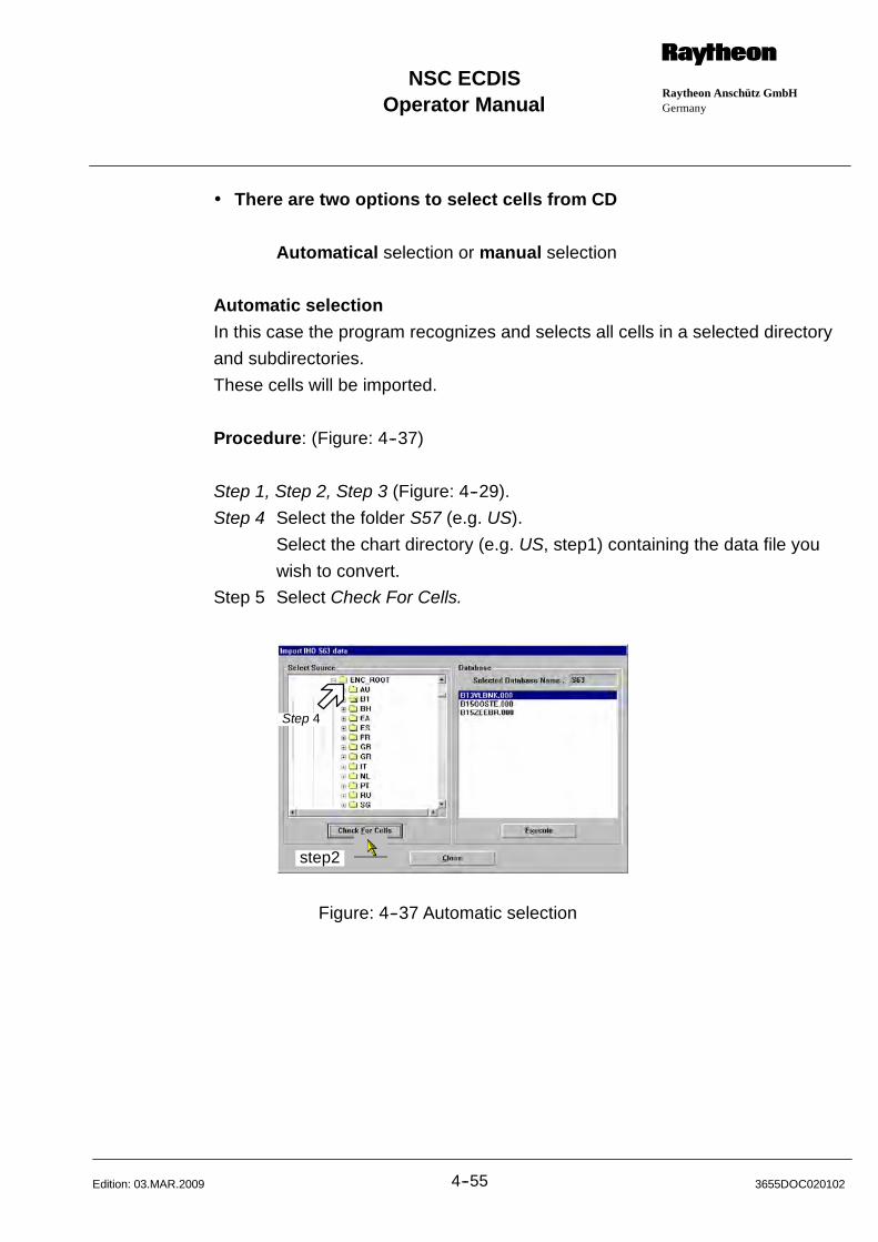
Operator ManualRaytheon Anschütz GmbHGermany
RNSC ECDIS
4--55 3655DOC020102Edition: 03.MAR.2009
There are two options to select cells from CD
Automatical selection or manual selection
Automatic selection
In this case the program recognizes and selects all cells in a selected directory
and subdirectories.
These cells will be imported.
Procedure: (Figure: 4--37)
Step 1, Step 2, Step 3 (Figure: 4--29).
Step 4 Select the folder S57 (e.g. US).
Select the chart directory (e.g. US, step1) containing the data file you
wish to convert.
Step 5 Select Check For Cells.
step2
Step 4
Figure: 4--37 Automatic selection

Operator Manual
4--563655DOC020102 Edition: 03.MAR.2009
Manual selection
In this case only the manually selected cells will be imported (without
subdirectories).
Procedure: (Figure: 4--38)
Step 1, Step 2, Step 3 (Figure: 4--29).
Step 4 Select the cell folder containing the data file you wish to convert.
Normally, the sub directory number is 0.
Step 4
Figure: 4--38 Manual selection
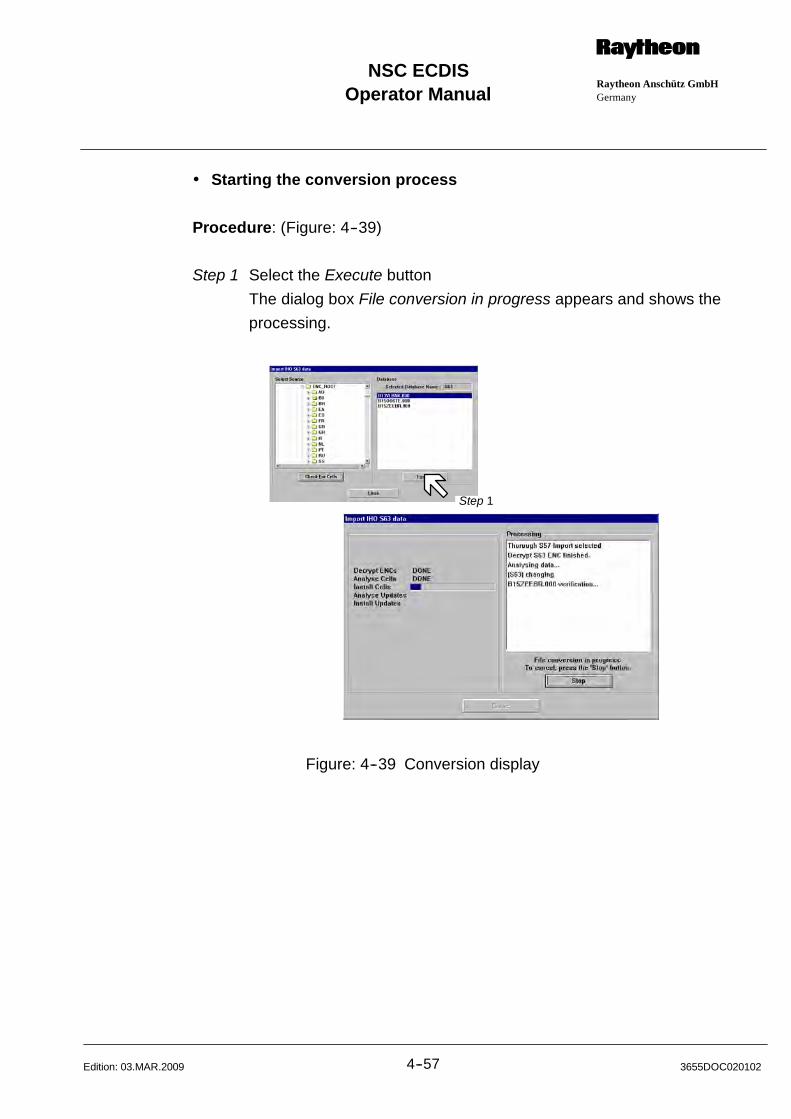
Operator ManualRaytheon Anschütz GmbHGermany
RNSC ECDIS
4--57 3655DOC020102Edition: 03.MAR.2009
Starting the conversion process
Procedure: (Figure: 4--39)
Step 1 Select the Execute button
The dialog box File conversion in progress appears and shows the
processing.
Step 1
Figure: 4--39 Conversion display

Operator Manual
4--583655DOC020102 Edition: 03.MAR.2009
The conversion process ends with following dialog box (Figure: 4--40).
Step 1 Select OK.
Step 1
Step 2
Figure: 4--40 Import of data completed
If you want to see the complete installation information, then select View Log
(Step 2). The following dialog window appears.
NoteIf the following message appears:
Following cells were not installed:XXXXXXXXXX
That means:The chart is invalid, contact thechart manufacturer and state to thecell identifier.
For a detailed error informationabout a cell in the summary list,please select the cell (step1).
Step 1
Figure: 4--41 Compilation log dialog box

Operator ManualRaytheon Anschütz GmbHGermany
RNSC ECDIS
4--59 3655DOC020102Edition: 03.MAR.2009
4.9 ARCS Installation
(see Annex--6.3 S57.. ARCS Charts Installation)
Procedure: (Figure: 4--42)
Step 1 Select Charts (menu bar)
Step 2 Select Installation
Step 3 Select ARCS Installation. The volume list shows already installed zones.
Place an ARCS chart CD into the CD drive.
S57 and CM93/3 Installation..ARCS Installation..DNC Installation..AML Installation...
Goto ARCS Chart
Info / Select...
S57 + CM93/3 Chart Catalog
Digitization... "
License "
Installation "
Updates "
Step 1
Step 2 Step 3
S57 and CM93/3 Installation..ARCS Installation..DNC Installation..
Figure: 4--42 ARCS Installation
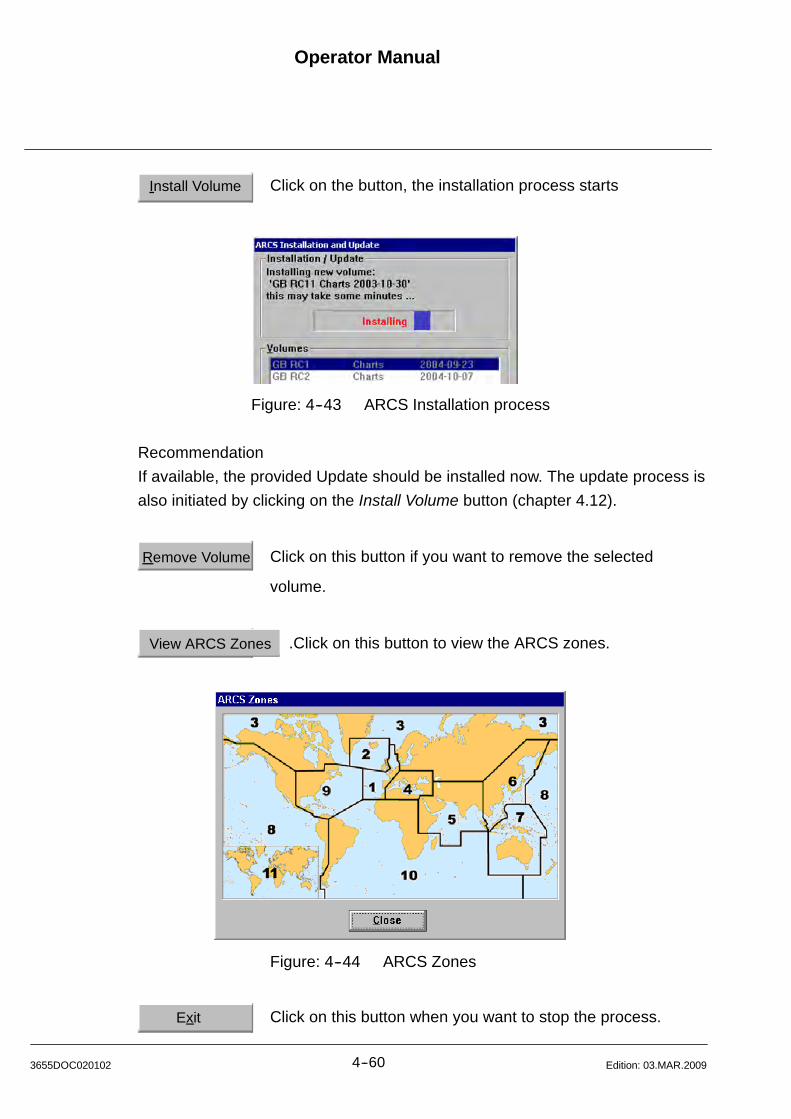
Operator Manual
4--603655DOC020102 Edition: 03.MAR.2009
Install Volume Click on the button, the installation process starts
Figure: 4--43 ARCS Installation process
Recommendation
If available, the provided Update should be installed now. The update process is
also initiated by clicking on the Install Volume button (chapter 4.12).
Remove Volume Click on this button if you want to remove the selected
volume.
View ARCS Zones .Click on this button to view the ARCS zones.
Figure: 4--44 ARCS Zones
Exit Click on this button when you want to stop the process.
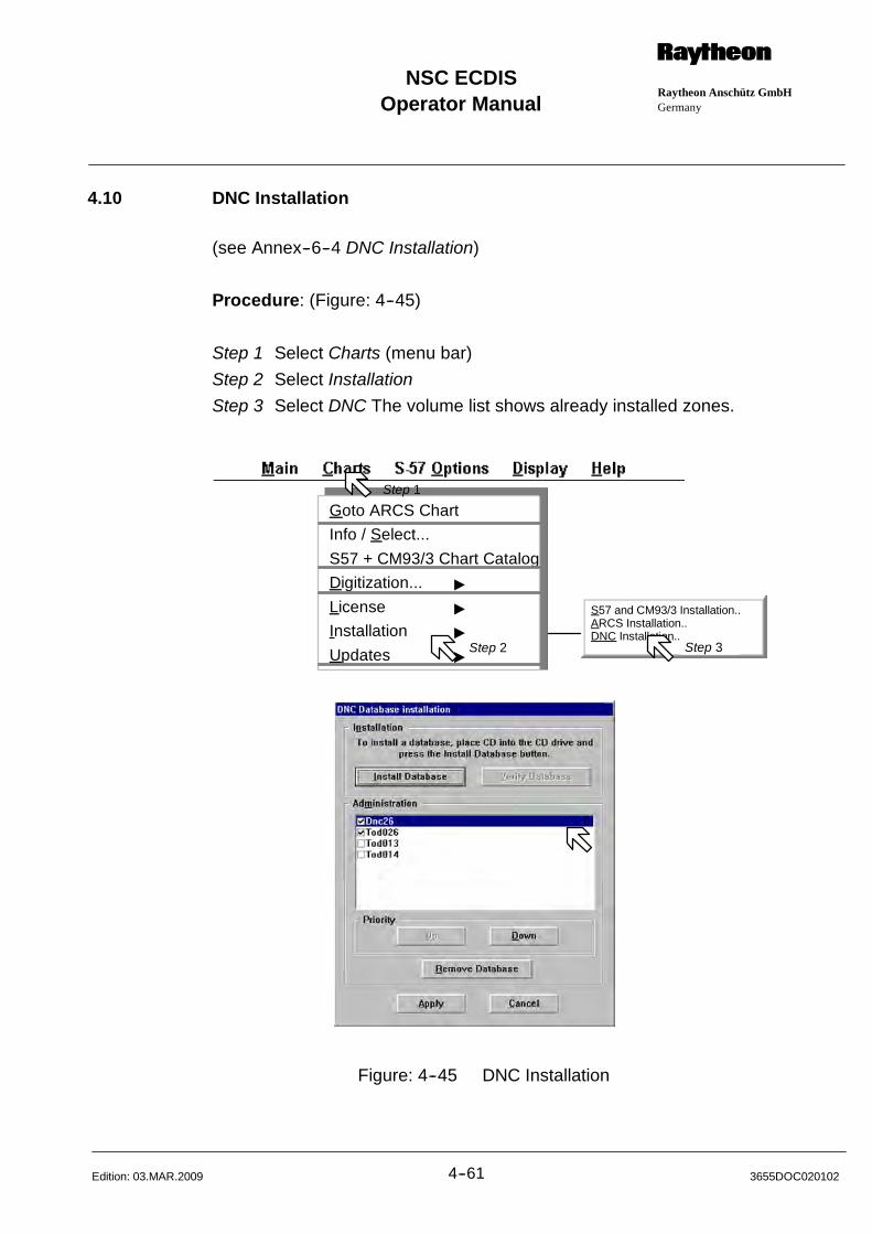
Operator ManualRaytheon Anschütz GmbHGermany
RNSC ECDIS
4--61 3655DOC020102Edition: 03.MAR.2009
4.10 DNC Installation
(see Annex--6--4 DNC Installation)
Procedure: (Figure: 4--45)
Step 1 Select Charts (menu bar)
Step 2 Select Installation
Step 3 Select DNC The volume list shows already installed zones.
S57 and CM93/3 Installation..ARCS Installation..DNC Installation..
Goto ARCS Chart
Info / Select...
S57 + CM93/3 Chart Catalog
Digitization... "
License "
Installation "
Updates "
Step 1
Step 2 Step 3
Figure: 4--45 DNC Installation
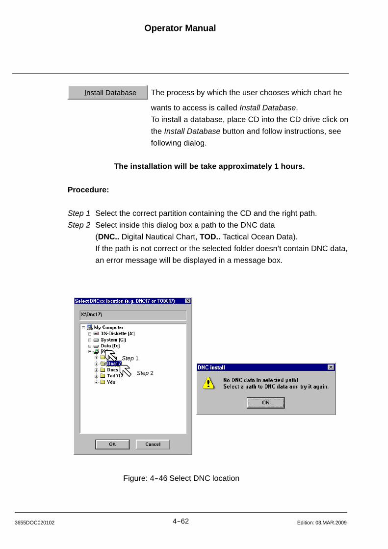
Step 1
Step 2
Operator Manual
4--623655DOC020102 Edition: 03.MAR.2009
Install Database The process by which the user chooses which chart he
wants to access is called Install Database.
To install a database, place CD into the CD drive click on
the Install Database button and follow instructions, see
following dialog.
The installation will be take approximately 1 hours.
Procedure:
Step 1 Select the correct partition containing the CD and the right path.
Step 2 Select inside this dialog box a path to the DNC data
(DNC.. Digital Nautical Chart, TOD.. Tactical Ocean Data).
If the path is not correct or the selected folder doesn’t contain DNC data,
an error message will be displayed in a message box.
Figure: 4--46 Select DNC location
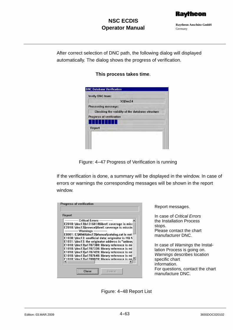
Operator ManualRaytheon Anschütz GmbHGermany
RNSC ECDIS
4--63 3655DOC020102Edition: 03.MAR.2009
After correct selection of DNC path, the following dialog will displayed
automatically. The dialog shows the progress of verification.
This process takes time.
Figure: 4--47 Progress of Verification is running
If the verification is done, a summary will be displayed in the window. In case of
errors or warnings the corresponding messages will be shown in the report
window.
Report messages.
In case of Critical Errorsthe Installation Processstops.Please contact the chartmanufacturer DNC.
In case of Warnings the Instal-lation Process is going on.Warnings describes locationspecific chartinformation.For questions, contact the chartmanufacture DNC.
Figure: 4--48 Report List
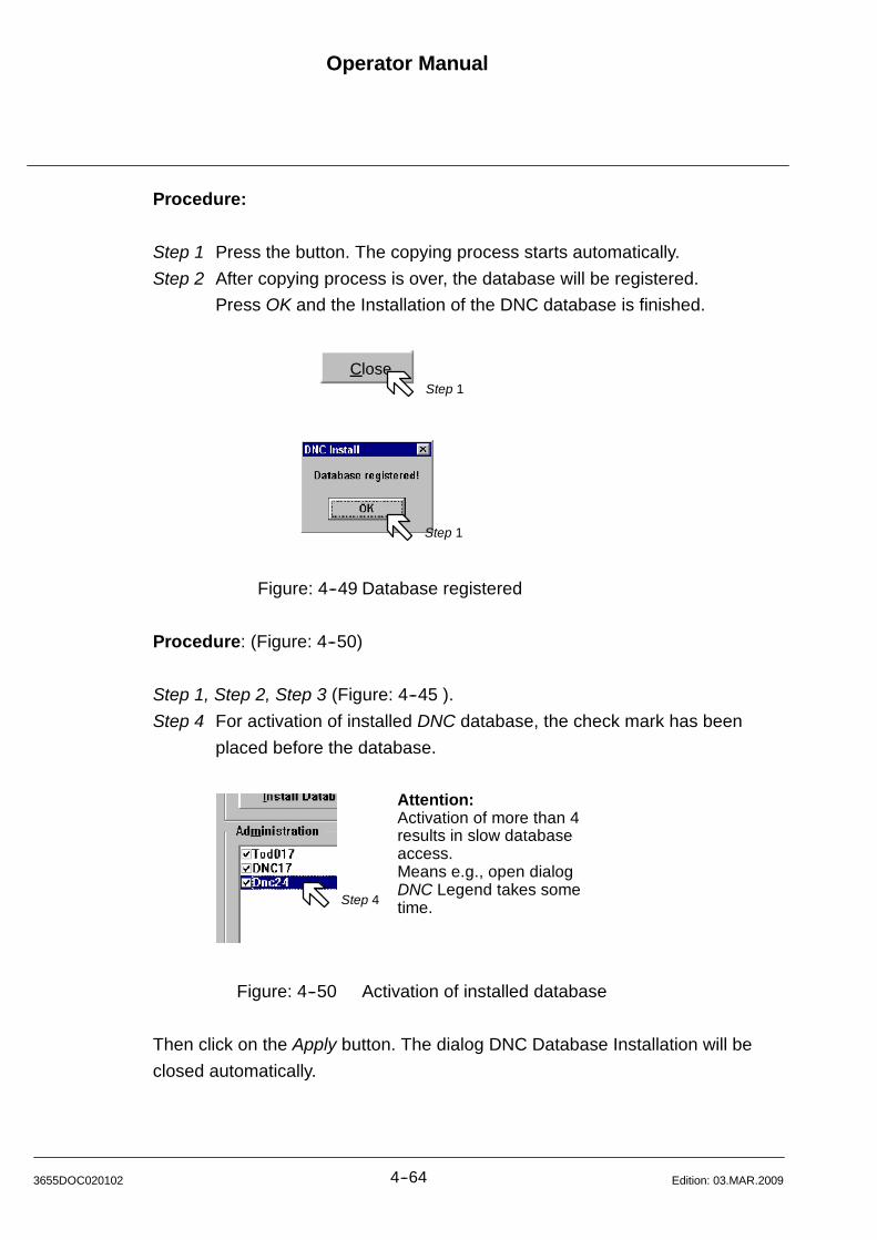
Operator Manual
4--643655DOC020102 Edition: 03.MAR.2009
Procedure:
Step 1 Press the button. The copying process starts automatically.
Step 2 After copying process is over, the database will be registered.
Press OK and the Installation of the DNC database is finished.
CloseStep 1
Step 1
Figure: 4--49 Database registered
Procedure: (Figure: 4--50)
Step 1, Step 2, Step 3 (Figure: 4--45 ).
Step 4 For activation of installed DNC database, the check mark has been
placed before the database.
Attention:Activation of more than 4results in slow databaseaccess.Means e.g., open dialogDNC Legend takes sometime.Step 4
Figure: 4--50 Activation of installed database
Then click on the Apply button. The dialog DNC Database Installation will be
closed automatically.

Operator ManualRaytheon Anschütz GmbHGermany
RNSC ECDIS
4--65 3655DOC020102Edition: 03.MAR.2009
Up Down
PriorityIf you want to modify the priority, select the database
you will have displayed first or last and click Priority
“Up” or “Down”.
Remove Database To remove a selected database, click on “Remove Data
base”.
Before the program deletes the selected database a
safety request dialog box appears with the question
Are you sure.....
NOTE
The removal of DNC database takes time.
Applyexecutes an action
Cancel a current procedure is aborted
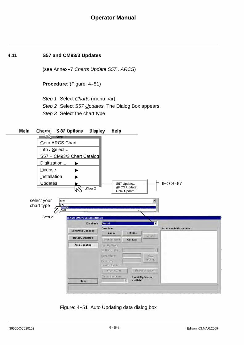
Operator Manual
4--663655DOC020102 Edition: 03.MAR.2009
4.11 S57 and CM93/3 Updates
(see Annex--7 Charts Update S57.. ARCS)
Procedure: (Figure: 4--51)
Step 1 Select Charts (menu bar).
Step 2 Select S57 Updates. The Dialog Box appears.
Step 3 Select the chart type
Goto ARCS Chart
Info / Select...
S57 + CM93/3 Chart Catalog
Digitization... "
License "
Installation "
Updates "
Step 2
Step 1
select yourchart type
Step 2
IHO S--67S57 Update..ARCS Update..DNC Update
Figure: 4--51 Auto Updating data dialog box

Operator ManualRaytheon Anschütz GmbHGermany
RNSC ECDIS
4--67 3655DOC020102Edition: 12.JULY.2012
Command Buttons:
Auto UpdatingAuto Updating is only supported for C--MAP databases
Auto Updating presents three download procedures.
Load AllWill load and install all available updates for the licensed
areas from the C--MAP server directly.
Get SizeWill check the size of the available update for the licensed areas.
Get ListWill get the list of available updates from the C--MAP server.
Load Selected Will load and install only the selected charts from the list.
The list has to be filled by the function Get List before.
Create Order Insert a USB--Stick, CD or DVD into the selected drive and select
Create Order.
An order file will be written on the USB--Stick. The name of the
order file is the name of the database with the extension ord
(e.g.:World .ord).
Take the USB--Stick with the order file to a system with Email
capabilities and send the order file as an attachment to the
C--MAP update server [email protected] .
You will receive an automatic answer with one or
more sequentially named answer files with the extension.
Save these attachments to the USB--Stick and take the
USB--Stick back to the NSC M Processor
Process Answer Select the soft button to install the updates.
Please ensure that all update answers are processed.
The sequence in which the answers are processed doesn’t
matter.
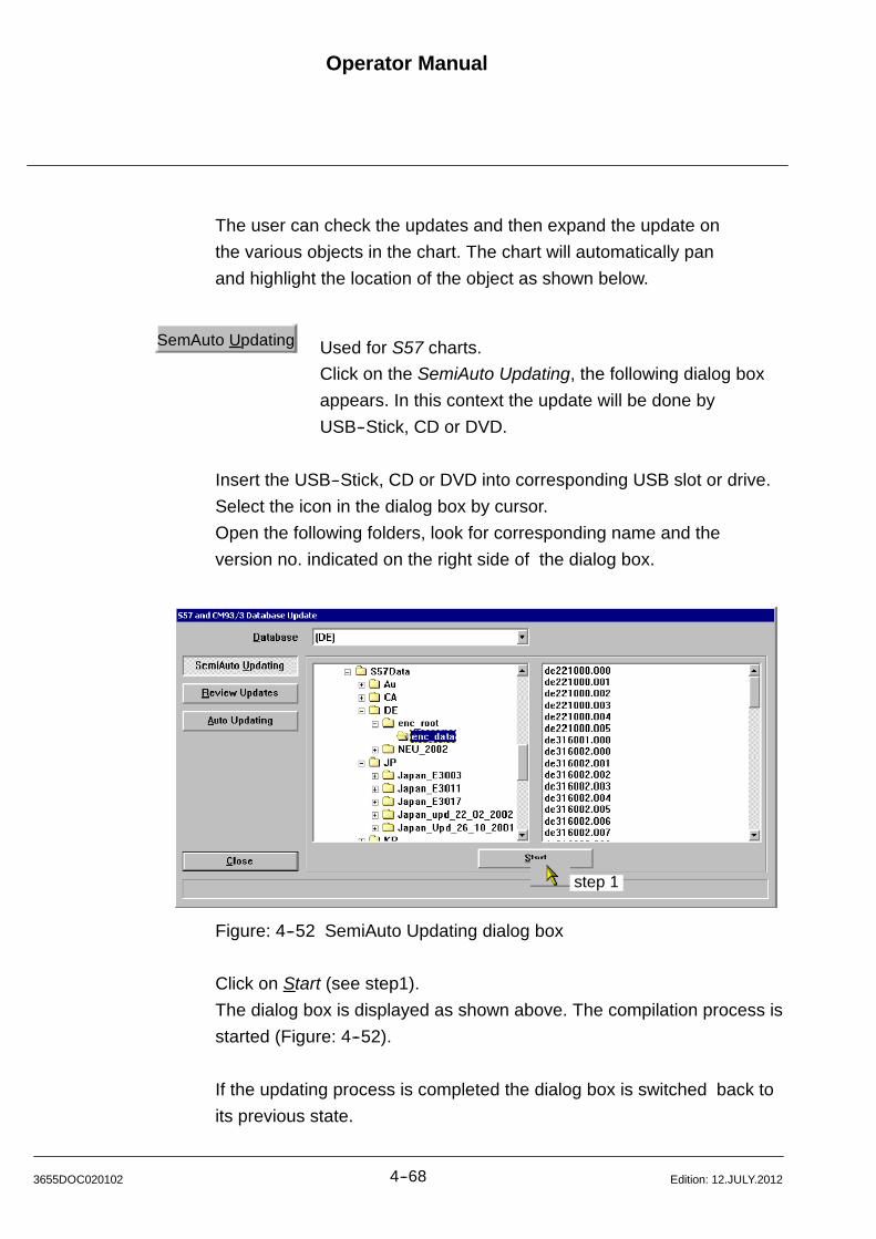
Operator Manual
4--683655DOC020102 Edition: 12.JULY.2012
The user can check the updates and then expand the update on
the various objects in the chart. The chart will automatically pan
and highlight the location of the object as shown below.
SemAuto Updating Used for S57 charts.
Click on the SemiAuto Updating, the following dialog box
appears. In this context the update will be done by
USB--Stick, CD or DVD.
Insert the USB--Stick, CD or DVD into corresponding USB slot or drive.
Select the icon in the dialog box by cursor.
Open the following folders, look for corresponding name and the
version no. indicated on the right side of the dialog box.
step 1
Figure: 4--52 SemiAuto Updating dialog box
Click on Start (see step1).
The dialog box is displayed as shown above. The compilation process is
started (Figure: 4--52).
If the updating process is completed the dialog box is switched back to
its previous state.
Operator ManualRaytheon Anschütz GmbHGermany
RNSC ECDIS
4--69 3655DOC020102Edition: 03.MAR.2009
Review Updates Clicking on the “Review Updates”, the following dialog
box appears. Now you can review the updates applied
listed by Auto Updating or by Semi Auto Updating.
Inside the Update Log window all updates are listed and stored with their
name, actual status, update version number and transfer date.
With an update of a zone, all previous area related--data of this zone are
erased.
Inside a Review window all applied updates are displayed
relative to their designated folders.
The designation of the version--number has been changed by this process.
Example: GBX01SW.002 changed into GBX01SW.C02 (C means
compiled)
For detailed information of an update, the respective folder has to be
selected via cursor.
With a double click ([Middle] button) the change--history is
displayed.
To display a special change (example: WRECK), this input has to be
activated by a double click.
To do this, the respective chart is displayed and the selected change
(example WRECK) is highlighted by a flashing circle.

Operator Manual
4--703655DOC020102 Edition: 03.MAR.2009
Figure: 4--53 Updating Log Review Updates
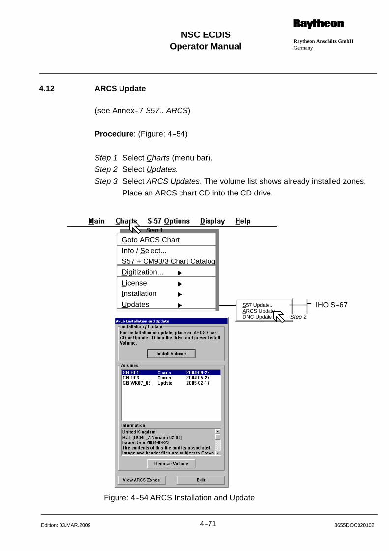
Operator ManualRaytheon Anschütz GmbHGermany
RNSC ECDIS
4--71 3655DOC020102Edition: 03.MAR.2009
4.12 ARCS Update
(see Annex--7 S57.. ARCS)
Procedure: (Figure: 4--54)
Step 1 Select Charts (menu bar).
Step 2 Select Updates.
Step 3 Select ARCS Updates. The volume list shows already installed zones.
Place an ARCS chart CD into the CD drive.
Goto ARCS Chart
Info / Select...
S57 + CM93/3 Chart Catalog
Digitization... "
License "
Installation "
Updates "
Step 1
IHO S--67S57 Update..ARCS Update..DNC Update Step 2
Figure: 4--54 ARCS Installation and Update
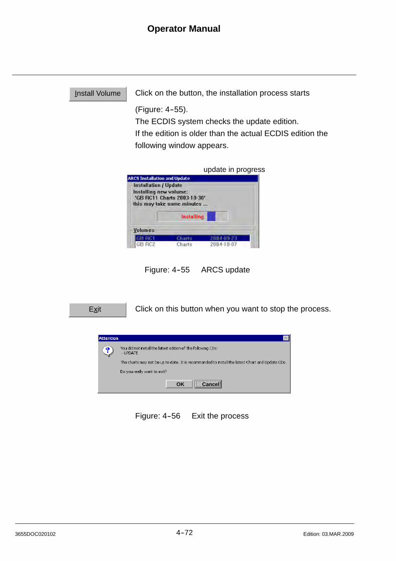
Operator Manual
4--723655DOC020102 Edition: 03.MAR.2009
Install Volume Click on the button, the installation process starts
(Figure: 4--55).
The ECDIS system checks the update edition.
If the edition is older than the actual ECDIS edition the
following window appears.
update in progress
Figure: 4--55 ARCS update
Exit Click on this button when you want to stop the process.
OK Cancel
Figure: 4--56 Exit the process
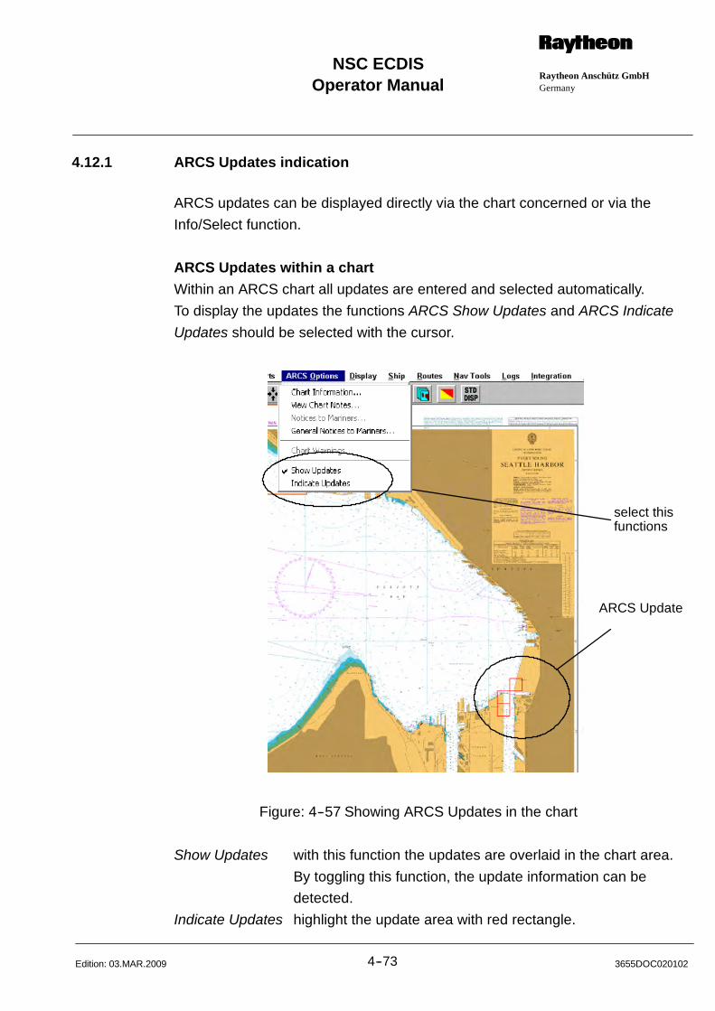
Operator ManualRaytheon Anschütz GmbHGermany
RNSC ECDIS
4--73 3655DOC020102Edition: 03.MAR.2009
4.12.1 ARCS Updates indication
ARCS updates can be displayed directly via the chart concerned or via the
Info/Select function.
ARCS Updates within a chart
Within an ARCS chart all updates are entered and selected automatically.
To display the updates the functions ARCS Show Updates and ARCS Indicate
Updates should be selected with the cursor.
ARCS Update
select thisfunctions
Figure: 4--57 Showing ARCS Updates in the chart
Show Updates with this function the updates are overlaid in the chart area.
By toggling this function, the update information can be
detected.
Indicate Updates highlight the update area with red rectangle.
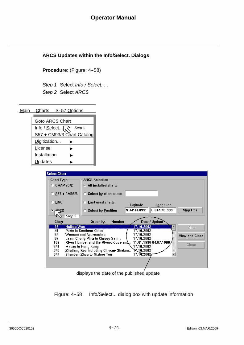
Operator Manual
4--743655DOC020102 Edition: 03.MAR.2009
ARCS Updates within the Info/Select. Dialogs
Procedure: (Figure: 4--58)
Step 1 Select Info / Select... .
Step 2 Select ARCS
Main Charts S--57 Options
displays the date of the published update
Goto ARCS Chart
Info / Select...
S57 + CM93/3 Chart Catalog
Digitization... "
License "
Installation "
Updates "
Step 1
Step 2
Figure: 4--58 Info/Select... dialog box with update information
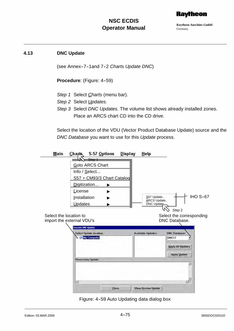
Operator ManualRaytheon Anschütz GmbHGermany
RNSC ECDIS
4--75 3655DOC020102Edition: 03.MAR.2009
4.13 DNC Update
(see Annex--7--1and 7--2 Charts Update DNC)
Procedure: (Figure: 4--59)
Step 1 Select Charts (menu bar).
Step 2 Select Updates.
Step 3 Select DNC Updates. The volume list shows already installed zones.
Place an ARCS chart CD into the CD drive.
Select the location of the VDU (Vector Product Database Update) source and the
DNC Database you want to use for this Update process.
Select the location toimport the external VDU’s
Select the correspondingDNC Database.
Goto ARCS Chart
Info / Select...
S57 + CM93/3 Chart Catalog
Digitization... "
License "
Installation "
Updates "
Step 1
IHO S--67S57 Update..ARCS Update..DNC Update
Step 2
Figure: 4--59 Auto Updating data dialog box
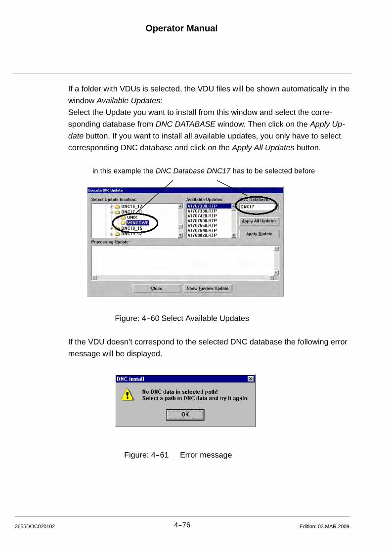
Operator Manual
4--763655DOC020102 Edition: 03.MAR.2009
If a folder with VDUs is selected, the VDU files will be shown automatically in the
window Available Updates:
Select the Update you want to install from this window and select the corre-
sponding database from DNC DATABASE window. Then click on the Apply Up-
date button. If you want to install all available updates, you only have to select
corresponding DNC database and click on the Apply All Updates button.
in this example the DNC Database DNC17 has to be selected before
Figure: 4--60 Select Available Updates
If the VDU doesn’t correspond to the selected DNC database the following error
message will be displayed.
Figure: 4--61 Error message
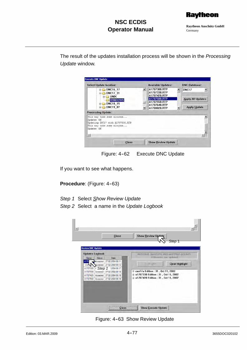
Operator ManualRaytheon Anschütz GmbHGermany
RNSC ECDIS
4--77 3655DOC020102Edition: 03.MAR.2009
The result of the updates installation process will be shown in the Processing
Update window.
Figure: 4--62 Execute DNC Update
If you want to see what happens.
Procedure: (Figure: 4--63)
Step 1 Select Show Review Update
Step 2 Select a name in the Update Logbook
Step 1
Step 2
Figure: 4--63 Show Review Update
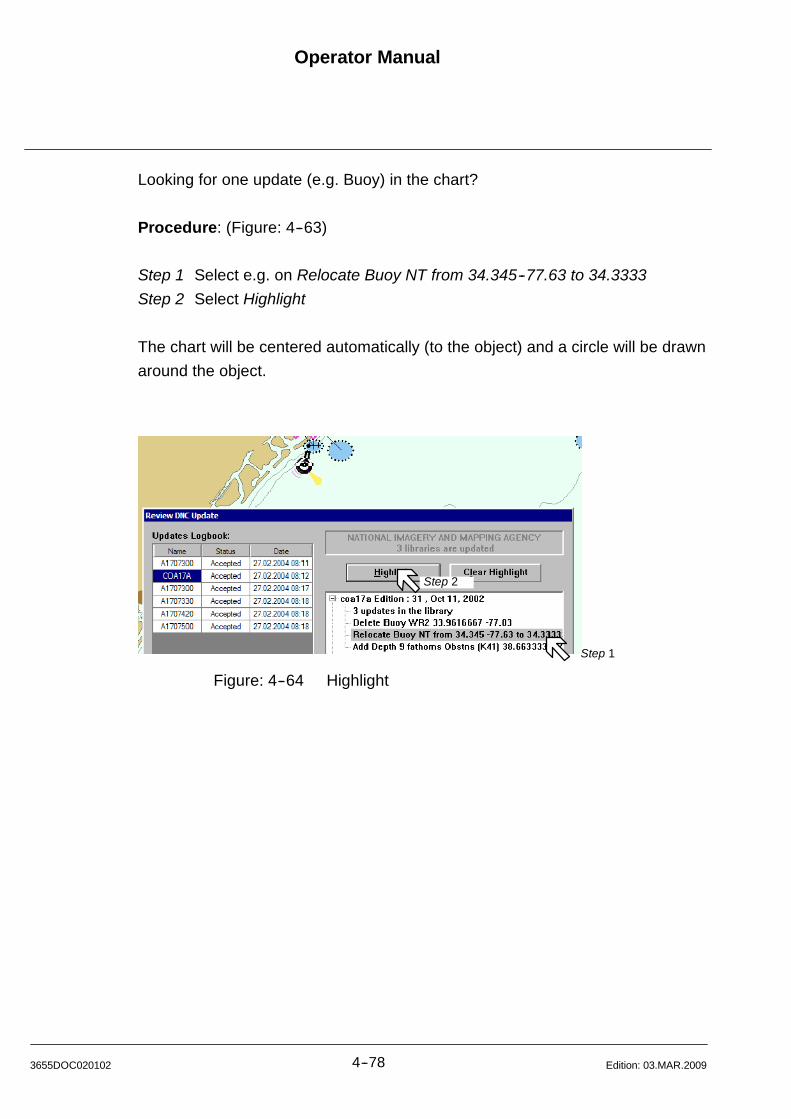
Operator Manual
4--783655DOC020102 Edition: 03.MAR.2009
Looking for one update (e.g. Buoy) in the chart?
Procedure: (Figure: 4--63)
Step 1 Select e.g. on Relocate Buoy NT from 34.345--77.63 to 34.3333
Step 2 Select Highlight
The chart will be centered automatically (to the object) and a circle will be drawn
around the object.
Step 1
Step 2
Figure: 4--64 Highlight
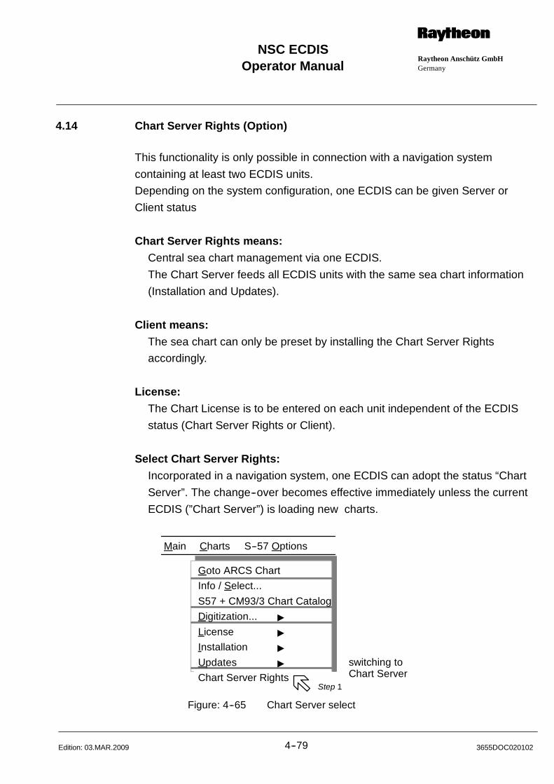
Operator ManualRaytheon Anschütz GmbHGermany
RNSC ECDIS
4--79 3655DOC020102Edition: 03.MAR.2009
4.14 Chart Server Rights (Option)
This functionality is only possible in connection with a navigation system
containing at least two ECDIS units.
Depending on the system configuration, one ECDIS can be given Server or
Client status
Chart Server Rights means:
Central sea chart management via one ECDIS.
The Chart Server feeds all ECDIS units with the same sea chart information
(Installation and Updates).
Client means:
The sea chart can only be preset by installing the Chart Server Rights
accordingly.
License:
The Chart License is to be entered on each unit independent of the ECDIS
status (Chart Server Rights or Client).
Select Chart Server Rights:
Incorporated in a navigation system, one ECDIS can adopt the status “Chart
Server”. The change--over becomes effective immediately unless the current
ECDIS (”Chart Server”) is loading new charts.
Main Charts S--57 Options
switching toChart Server
Goto ARCS Chart
Info / Select...
S57 + CM93/3 Chart Catalog
Digitization... "
License "
Installation "
Updates "
Chart Server RightsStep 1
Figure: 4--65 Chart Server select

Operator Manual
4--803655DOC020102 Edition: 03.MAR.2009
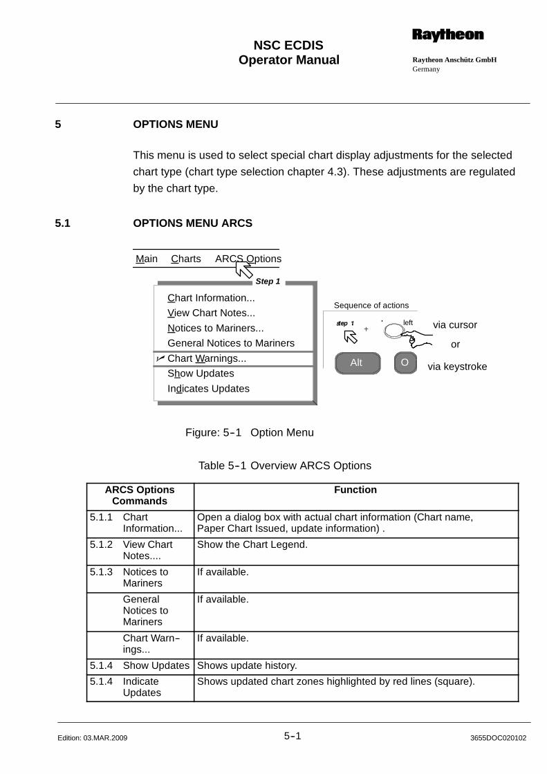
Operator Manual Raytheon Anschütz GmbHGermany
RNSC ECDIS
5--1 3655DOC020102Edition: 03.MAR.2009
5 OPTIONS MENU
This menu is used to select special chart display adjustments for the selected
chart type (chart type selection chapter 4.3). These adjustments are regulated
by the chart type.
5.1 OPTIONS MENU ARCS
Alt O
via cursor
via keystroke
or
Main Charts ARCS Options
Sequence of actionsChart Information...
View Chart Notes...
Notices to Mariners...
General Notices to Mariners
Chart Warnings...
Show Updates
Indicates Updates
n
Step 1
left
Figure: 5--1 Option Menu
Table 5--1 Overview ARCS Options
ARCS OptionsCommands
Function
5.1.1 ChartInformation...
Open a dialog box with actual chart information (Chart name,Paper Chart Issued, update information) .
5.1.2 View ChartNotes....
Show the Chart Legend.
5.1.3 Notices toMariners
If available.
GeneralNotices toMariners
If available.
Chart Warn--ings...
If available.
5.1.4 Show Updates Shows update history.
5.1.4 IndicateUpdates
Shows updated chart zones highlighted by red lines (square).
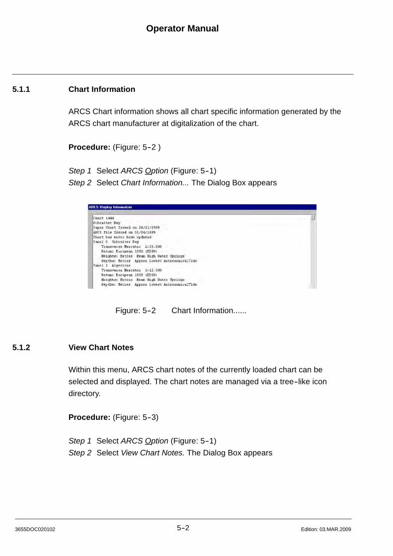
Operator Manual
5--23655DOC020102 Edition: 03.MAR.2009
5.1.1 Chart Information
ARCS Chart information shows all chart specific information generated by the
ARCS chart manufacturer at digitalization of the chart.
Procedure: (Figure: 5--2 )
Step 1 Select ARCS Option (Figure: 5--1)
Step 2 Select Chart Information... The Dialog Box appears
Figure: 5--2 Chart Information......
5.1.2 View Chart Notes
Within this menu, ARCS chart notes of the currently loaded chart can be
selected and displayed. The chart notes are managed via a tree--like icon
directory.
Procedure: (Figure: 5--3)
Step 1 Select ARCS Option (Figure: 5--1)
Step 2 Select View Chart Notes. The Dialog Box appears
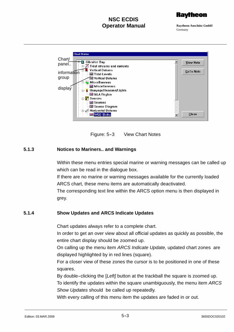
Operator Manual Raytheon Anschütz GmbHGermany
RNSC ECDIS
5--3 3655DOC020102Edition: 03.MAR.2009
Chart/panel..
informationgroup
display
Figure: 5--3 View Chart Notes
5.1.3 Notices to Mariners.. and Warnings
Within these menu entries special marine or warning messages can be called up
which can be read in the dialogue box.
If there are no marine or warning messages available for the currently loaded
ARCS chart, these menu items are automatically deactivated.
The corresponding text line within the ARCS option menu is then displayed in
grey.
5.1.4 Show Updates and ARCS Indicate Updates
Chart updates always refer to a complete chart.
In order to get an over view about all official updates as quickly as possible, the
entire chart display should be zoomed up.
On calling up the menu item ARCS Indicate Update, updated chart zones are
displayed highlighted by in red lines (square).
For a closer view of these zones the cursor is to be positioned in one of these
squares.
By double--clicking the [Left] button at the trackball the square is zoomed up.
To identify the updates within the square unambiguously, the menu item ARCS
Show Updates should be called up repeatedly.
With every calling of this menu item the updates are faded in or out.
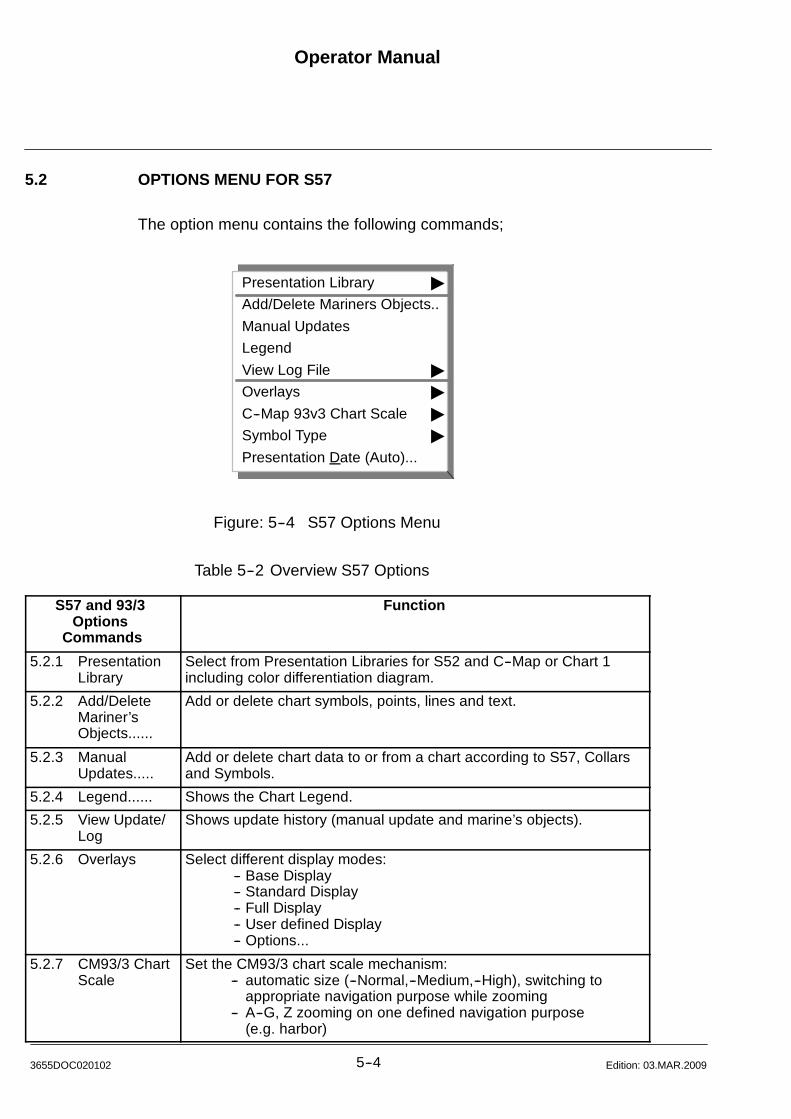
Operator Manual
5--43655DOC020102 Edition: 03.MAR.2009
5.2 OPTIONS MENU FOR S57
The option menu contains the following commands;
Presentation Library "
Add/Delete Mariners Objects..
Manual Updates
Legend
View Log File "
Overlays "
C--Map 93v3 Chart Scale "
Symbol Type "
Presentation Date (Auto)...
Figure: 5--4 S57 Options Menu
Table 5--2 Overview S57 Options
S57 and 93/3Options
Commands
Function
5.2.1 PresentationLibrary
Select from Presentation Libraries for S52 and C--Map or Chart 1including color differentiation diagram.
5.2.2 Add/DeleteMariner’sObjects......
Add or delete chart symbols, points, lines and text.
5.2.3 ManualUpdates.....
Add or delete chart data to or from a chart according to S57, Collarsand Symbols.
5.2.4 Legend...... Shows the Chart Legend.
5.2.5 View Update/Log
Shows update history (manual update and marine’s objects).
5.2.6 Overlays Select different display modes:-- Base Display-- Standard Display-- Full Display-- User defined Display-- Options...
5.2.7 CM93/3 ChartScale
Set the CM93/3 chart scale mechanism:-- automatic size (--Normal,--Medium,--High), switching to
appropriate navigation purpose while zooming-- A--G, Z zooming on one defined navigation purpose
(e.g. harbor)

Operator Manual Raytheon Anschütz GmbHGermany
RNSC ECDIS
5--5 3655DOC020102Edition: 03.MAR.2009
S57 and 93/3Options
Commands
Function
5.2.8 Symbol Type Change symbol type from simplified symbol to traditional symbols orthe other way.
5.2.9 PresentationDate
For the presentation of the dependant chart objects.

Operator Manual
5--63655DOC020102 Edition: 03.MAR.2009
5.2.1 Presentation Library
With this menu item, the user can select from different presentations for the
currently loaded chart S57.
In accordance with IHO--S52 “Specifications of Chart Content and Display
Aspects of ECDIS” colors and symbol, this menu is comprising Test Presentation
Library and Chart_1 besides the Standard Symbol Library.
Procedure: (Figure: 5--5)
Step 1 Select S--57 Option (Figure: 5--1)
Step 2 Select Presentation Library. The dialog box appears.
S52 Edition 3.4
C--Map
Chart1
Figure: 5--5 Presentation Library dialogue box
5.2.1.1 S52 Edition 3.4
This menu applies the Standard Symbol Presentation (IHO--S52).
5.2.1.2 C--Map .....
This menu item allows to apply the Symbol Presentation provided by the chart
manufacturer C--Map.
5.2.1.3 Chart 1 selecting
Chart 1 Presentation, all Symbols used for the ECDIS display are shown in a
graphical presentation. Their shape and colour are in correspondence to IHO
publication S52.
Check the graphical presentation e.g. color on the display or compare the
symbol with the “Colour and Symbol Specifications for ECDIS” handbook.
Operator Manual Raytheon Anschütz GmbHGermany
RNSC ECDIS
5--7 3655DOC020102Edition: 03.MAR.2009
Procedure: (Figure: 5--6)
Step 1 Select Presentation Library. The Dialog Box appears.
Step 2 Select Chart1. A information window appears. Select OK, the
Presentation Library List appears.
Step 3 Select the Zoom In function from the Display Menu
Step 4 Position the Zoom In cursor to one of the corners of the color region,
then press and continue to hold down the [Left] button.
Drag the cursor so that the Zoom In box covers the region to magnify.
Release the trackball button when you are done.
Step 5 The following detailed window appears
Step 6 Check the diagonal color line presentation on the ECDIS display or
compare the diagonal color line pictures with the “Color and Symbol
Specifications for ECDIS” handbook.
Step 7 Do the check by changing the Display Color combinations (chapter
Display 6.1.8) like,
Bright Sun Colors, Day Colors, Day Colors, Night Colors.
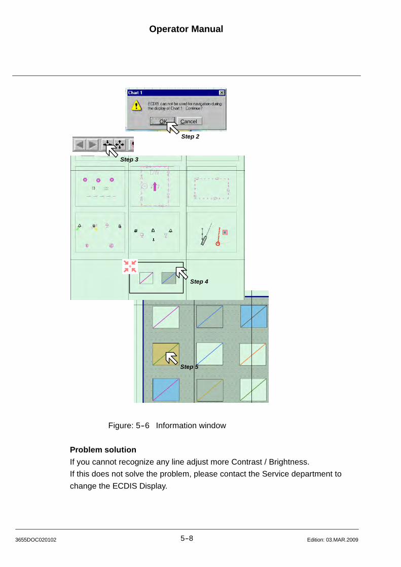
Operator Manual
5--83655DOC020102 Edition: 03.MAR.2009
OK Cancel
Step 2
Step 3
Step 4
Step 5
Figure: 5--6 Information window
Problem solution
If you cannot recognize any line adjust more Contrast / Brightness.
If this does not solve the problem, please contact the Service department to
change the ECDIS Display.
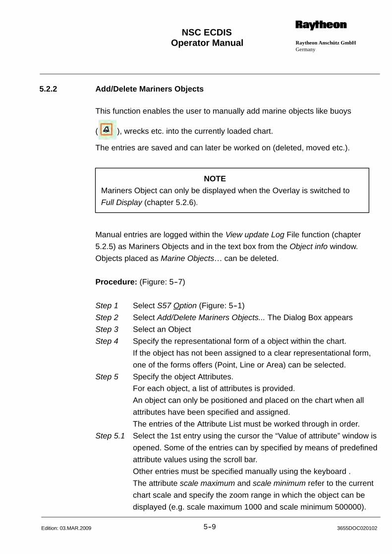
Operator Manual Raytheon Anschütz GmbHGermany
RNSC ECDIS
5--9 3655DOC020102Edition: 03.MAR.2009
5.2.2 Add/Delete Mariners Objects
This function enables the user to manually add marine objects like buoys
( ), wrecks etc. into the currently loaded chart.
The entries are saved and can later be worked on (deleted, moved etc.).
NOTE
Mariners Object can only be displayed when the Overlay is switched to
Full Display (chapter 5.2.6).
Manual entries are logged within the View update Log File function (chapter
5.2.5) as Mariners Objects and in the text box from the Object info window.
Objects placed as Marine Objects can be deleted.
Procedure: (Figure: 5--7)
Step 1 Select S57 Option (Figure: 5--1)
Step 2 Select Add/Delete Mariners Objects... The Dialog Box appears
Step 3 Select an Object
Step 4 Specify the representational form of a object within the chart.
If the object has not been assigned to a clear representational form,
one of the forms offers (Point, Line or Area) can be selected.
Step 5 Specify the object Attributes.
For each object, a list of attributes is provided.
An object can only be positioned and placed on the chart when all
attributes have been specified and assigned.
The entries of the Attribute List must be worked through in order.
Step 5.1 Select the 1st entry using the cursor the “Value of attribute” window is
opened. Some of the entries can by specified by means of predefined
attribute values using the scroll bar.
Other entries must be specified manually using the keyboard .
The attribute scale maximum and scale minimum refer to the current
chart scale and specify the zoom range in which the object can be
displayed (e.g. scale maximum 1000 and scale minimum 500000).
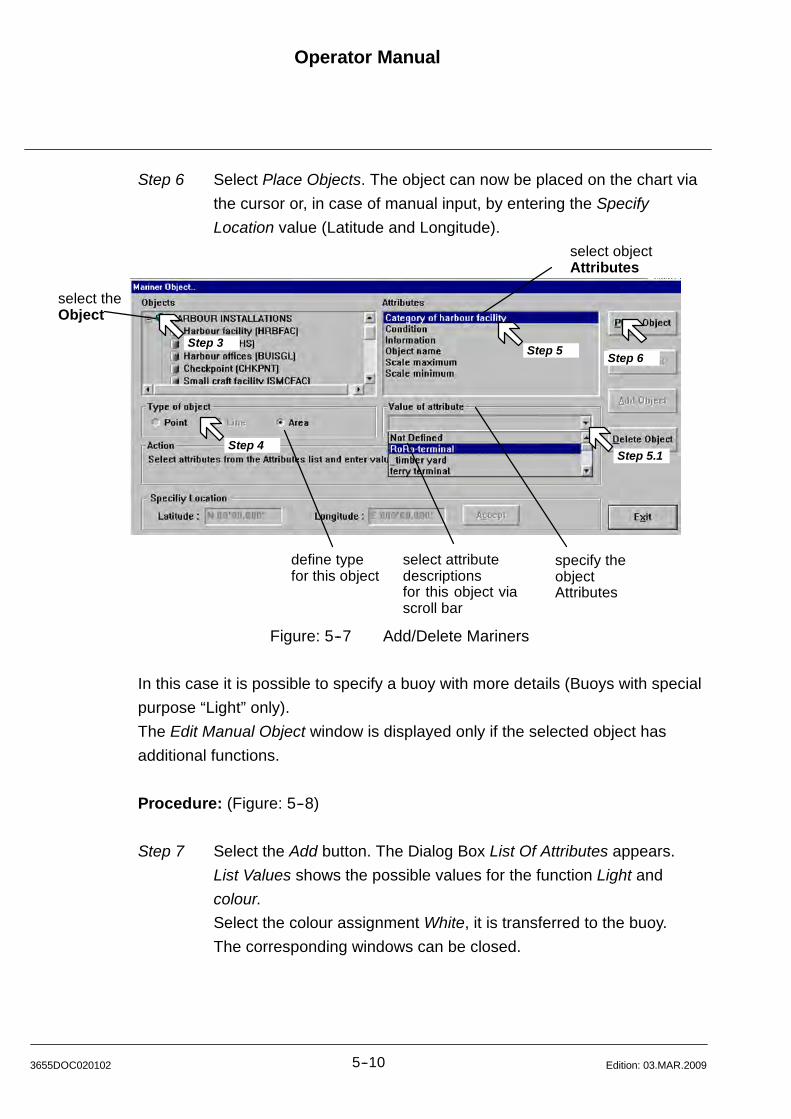
Operator Manual
5--103655DOC020102 Edition: 03.MAR.2009
Step 6 Select Place Objects. The object can now be placed on the chart via
the cursor or, in case of manual input, by entering the Specify
Location value (Latitude and Longitude).
select theObject
specify theobjectAttributes
define typefor this object
select objectAttributes
select attributedescriptionsfor this object viascroll bar
Step 3Step 5
Step 5.1Step 4
Step 6
Figure: 5--7 Add/Delete Mariners
In this case it is possible to specify a buoy with more details (Buoys with special
purpose “Light” only).
The Edit Manual Object window is displayed only if the selected object has
additional functions.
Procedure: (Figure: 5--8)
Step 7 Select the Add button. The Dialog Box List Of Attributes appears.
List Values shows the possible values for the function Light and
colour.
Select the colour assignment White, it is transferred to the buoy.
The corresponding windows can be closed.

Operator Manual Raytheon Anschütz GmbHGermany
RNSC ECDIS
5--11 3655DOC020102Edition: 03.MAR.2009
Step 7
Figure: 5--8 Edit Manual Objects dialog box
By pressing the Close key, the cursor is released for positioning the buoy .
The positioned buoy is displayed within the light cone code within the chart.
Figure: 5--9 Add a special object info
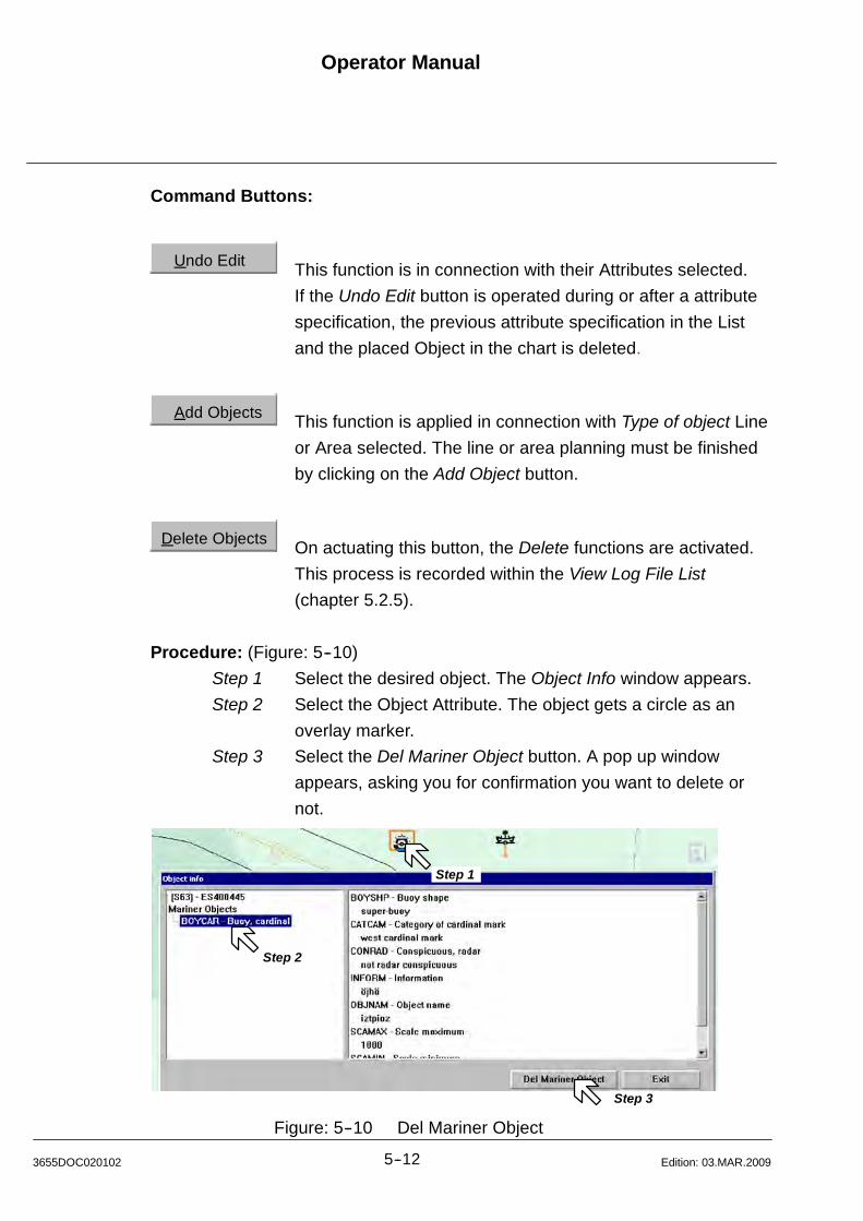
Operator Manual
5--123655DOC020102 Edition: 03.MAR.2009
Command Buttons:
Undo Edit This function is in connection with their Attributes selected.
If the Undo Edit button is operated during or after a attribute
specification, the previous attribute specification in the List
and the placed Object in the chart is deleted.
Add Objects This function is applied in connection with Type of object Line
or Area selected. The line or area planning must be finished
by clicking on the Add Object button.
Delete Objects On actuating this button, the Delete functions are activated.
This process is recorded within the View Log File List
(chapter 5.2.5).
Procedure: (Figure: 5--10)
Step 1 Select the desired object. The Object Info window appears.
Step 2 Select the Object Attribute. The object gets a circle as an
overlay marker.
Step 3 Select the Del Mariner Object button. A pop up window
appears, asking you for confirmation you want to delete or
not.
Step 1
Step 2
Step 3
Figure: 5--10 Del Mariner Object
Operator Manual Raytheon Anschütz GmbHGermany
RNSC ECDIS
5--13 3655DOC020102Edition: 03.MAR.2009
5.2.3 Manual Updates
This menu item is designed for the official manual chart correction (equivalent to
Notes to Mariners for paper charts).
Chart corrections are announced either from the chart manufacturer or regularly
issued Notices to Mariners.
The entries are saved for the sea chart and cannot be visibly deleted from their
position.
The object is either deleted or marked as deleted by “ / ” .
The entries can be moved to another place in the chart. Moved entries are
marked by “ “ . Moved entries can be deleted from their position.
New Objects can be placed as Marine Updatesmarked by “ “ .
These Objects can be deleted.
The official entries are logged as Manual Updates in the View Log File function
(chapter 5.2.5) and in the text box from the Object info window .
Procedure: (Figure: 5--11)
Step 1 Select S--57 Option (Figure: 5--1)
Step 2 Select Manual Updates. The Dialog Box appears (Figure: 5--11).
Step 3 Select an Object
Step 4 Specify the representational form of a object within the chart.
If the object has not been assigned to a clear representational form,
one of the forms offers (Point, Line or Area) can be selected.
Step 5 Specify the object Attributes.
For each object, a list of attributes is provided.
The attribute list has to be modified according to the update
information received.
Step 5.1 Select the 1st entry using the cursor the “Value of attribute” window is
opened. Some of the entries can by specified by means of predefined
attribute values using the scroll bar.
Other entries must be specified manually using the keyboard .
The attribute scale maximum and scale minimum refer to the current
chart scale and specify the zoom range in which the object can be

Operator Manual
5--143655DOC020102 Edition: 03.MAR.2009
displayed (e.g. scale maximum 1000 and scale minimum 500000).
Step 6 Select Place Objects. The object can now be placed on the chart via
the cursor or, in case of manual input, by entering the Specify
Location value (Latitude and Longitude).
select theobject
define typefor this object
select object
Attributes
specify attribute descrip-tions, if possible for thisobject via scroll bar
Step 3
Step 4
Step 5
Step 5.1
Step 6
Figure: 5--11 Manual Updates
In this case it is possible to specify a buoy with more details (Buoys with special
purpose “Light” only).
The Edit Manual Object window is displayed only if the selected object has
additional functions.
Procedure: (Figure: 5--12)
Step 7 Select the Add button (Figure: 5--12). The Dialog Box List Of
Attributes appears.
List Values shows the possible values for the function Light and
colour.
Select the colour assignment White, it is transferred to the buoy.
The corresponding windows can be closed.

Operator Manual Raytheon Anschütz GmbHGermany
RNSC ECDIS
5--15 3655DOC020102Edition: 03.MAR.2009
Step 7
Figure: 5--12 Edit Manual Objects dialog box
By pressing the Close key, the cursor is released for positioning the buoy .
The positioned buoy is displayed within the light cone code within the chart.
Figure: 5--13 Add a special object info
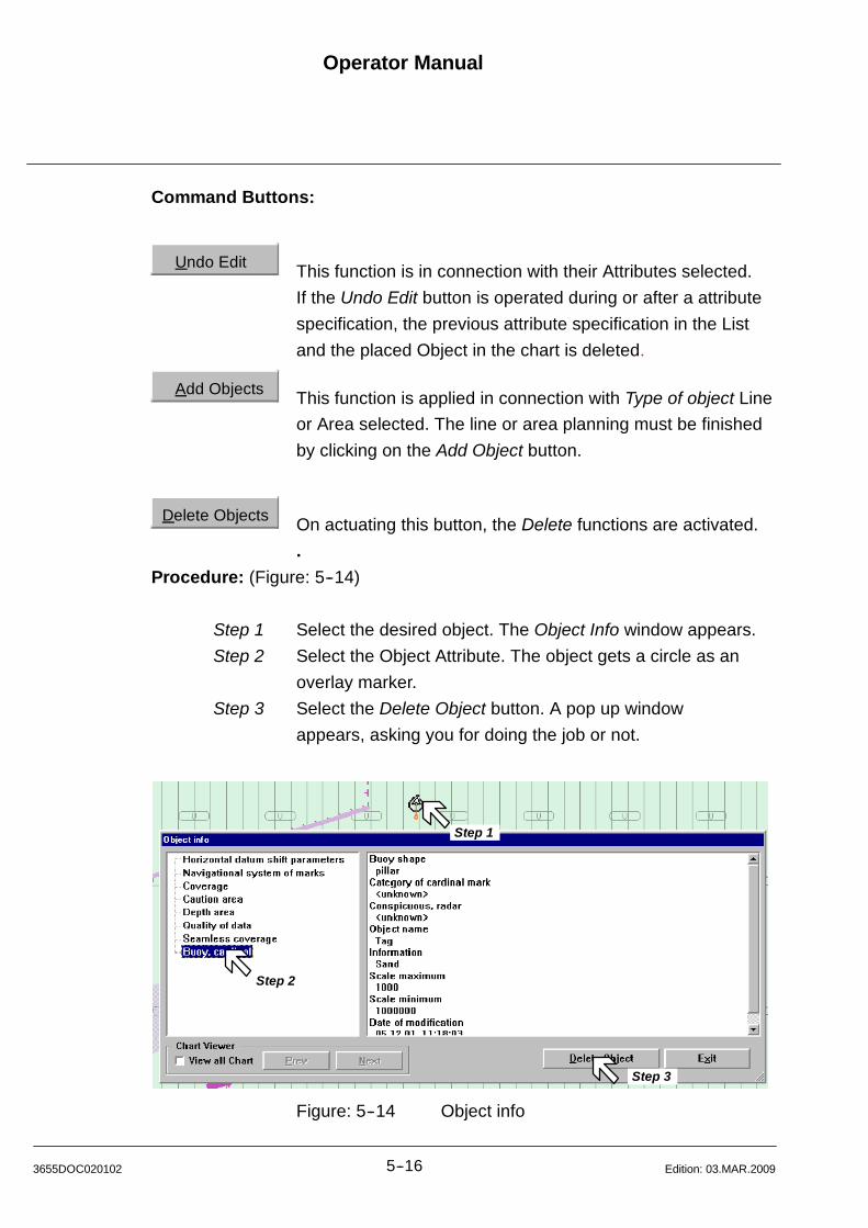
Operator Manual
5--163655DOC020102 Edition: 03.MAR.2009
Command Buttons:
Undo Edit This function is in connection with their Attributes selected.
If the Undo Edit button is operated during or after a attribute
specification, the previous attribute specification in the List
and the placed Object in the chart is deleted.
Add Objects This function is applied in connection with Type of object Line
or Area selected. The line or area planning must be finished
by clicking on the Add Object button.
Delete Objects On actuating this button, the Delete functions are activated.
.
Procedure: (Figure: 5--14)
Step 1 Select the desired object. The Object Info window appears.
Step 2 Select the Object Attribute. The object gets a circle as an
overlay marker.
Step 3 Select the Delete Object button. A pop up window
appears, asking you for doing the job or not.
Step 1
Step 2
Step 3
Figure: 5--14 Object info
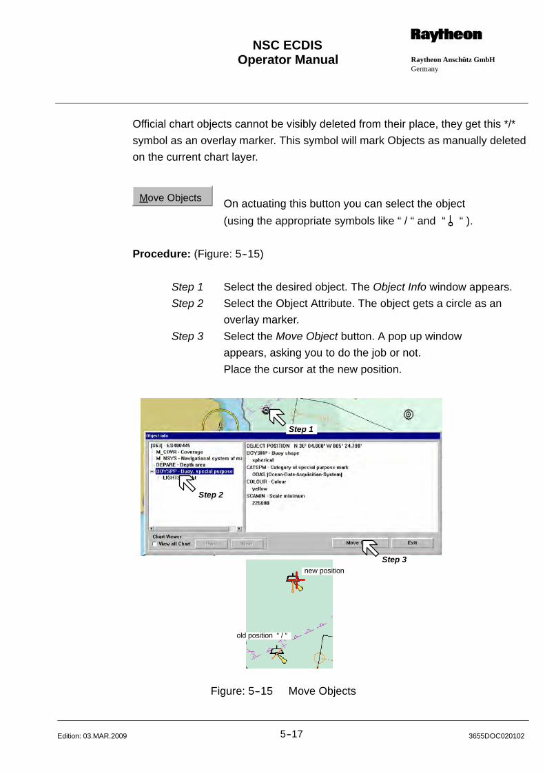
Operator Manual Raytheon Anschütz GmbHGermany
RNSC ECDIS
5--17 3655DOC020102Edition: 03.MAR.2009
Official chart objects cannot be visibly deleted from their place, they get this */*
symbol as an overlay marker. This symbol will mark Objects as manually deleted
on the current chart layer.
Move Objects On actuating this button you can select the object
(using the appropriate symbols like “ / “ and “ “ ).
Procedure: (Figure: 5--15)
Step 1 Select the desired object. The Object Info window appears.
Step 2 Select the Object Attribute. The object gets a circle as an
overlay marker.
Step 3 Select the Move Object button. A pop up window
appears, asking you to do the job or not.
Place the cursor at the new position.
Step 1
Step 2
Step 3new position
old position “ / “
Figure: 5--15 Move Objects
Operator Manual
5--183655DOC020102 Edition: 03.MAR.2009
Chart Viewer:
S57 charts are made up of several scale ranges. The information extent of the
scale ranges varies and is determined via the penetration depth (zoom in/out).
If an object is now deleted or inserted in a scale range, this action is restricted
only to this scale range.
Previous or subsequent scale ranges are not considered in this process.
This means that deleted objects are still displayed there, new objects are
missing.
In order to avoid this missing information, the object information of the scale
ranges must be updated after deletion or addition.
After the deletion/insertion of an object, the following steps are recommended.
Select View all chart, it will display the updated object at the first navigation
purpose where this object is available centred on the chart.
The displayed dataset will be automatically be presented at the smallest scale
available.
At the same time tree list box and the Delete Object button will be enabled.
Press on the Next button to move to next navigation purpose (e.g. harbour).
Now you can navigate through all chart scales using the Next or Prev button.
If there is no smaller scale containing the object then the Next button will be
disabled.
If you are at most detailed navigation purpose then Prev button will be disable.
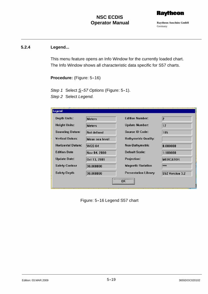
Operator Manual Raytheon Anschütz GmbHGermany
RNSC ECDIS
5--19 3655DOC020102Edition: 03.MAR.2009
5.2.4 Legend...
This menu feature opens an Info Window for the currently loaded chart.
The Info Window shows all characteristic data specific for S57 charts.
Procedure: (Figure: 5--16)
Step 1 Select S--57 Options (Figure: 5--1).
Step 2 Select Legend.
Figure: 5--16 Legend S57 chart
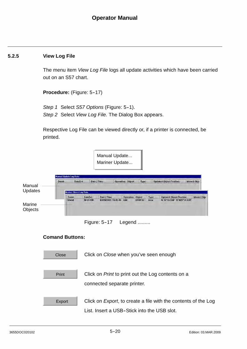
Operator Manual
5--203655DOC020102 Edition: 03.MAR.2009
5.2.5 View Log File
The menu item View Log File logs all update activities which have been carried
out on an S57 chart.
Procedure: (Figure: 5--17)
Step 1 Select S57 Options (Figure: 5--1).
Step 2 Select View Log File. The Dialog Box appears.
Respective Log File can be viewed directly or, if a printer is connected, be
printed.
ManualUpdates
MarineObjects
Manual Update...
Mariner Update...
Figure: 5--17 Legend .........
Comand Buttons:
Close Click on Close when you’ve seen enough
Print Click on Print to print out the Log contents on a
connected separate printer.
Export Click on Export, to create a file with the contents of the Log
List. Insert a USB--Stick into the USB slot.

Operator Manual Raytheon Anschütz GmbHGermany
RNSC ECDIS
5--21 3655DOC020102Edition: 03.MAR.2009
5.2.6 Overlays
This menu item allows the user to select the SENC information (System
Electronic Navigational Chart) to be displayed on the current chart.
Procedure: (Figure: 5--18)
Step 1 Select S57 Options (Figure: 5--1).
Step 2 Select Overlays. The Dialog Box appears.
Figure: 5--18 S57 Overlays
Base Display permanently retained on the ECDIS display, consisting of:
1 coastline (high water);
2 own ship’s safety contour (to be selected by the mariner);
3 indication of isolated underwater dangers of depths less than the safety
contour which lie within the safe waters defined by the safety contour;
4 indication of isolated dangers which lie within the safe water defined by the
safety contour such as bridges, overhead wires, etc., and including buoys
and beacons whether or not these are being used as aids to navigation;
5 traffic routing systems;
6 fixed and floating aids to navigation;
Standard Display to be displayed when the chart is first displayed by ECDIS,
consisting of:
1 the Base Display plus;
2 drying line;
3 boundaries of fairways, channels, etc.;
4 visual and radar conspicuous features;
5 prohibited and restricted areas;
Operator Manual
5--223655DOC020102 Edition: 03.MAR.2009
6 chart scale boundaries;
7 indication of cautionary notes;
Full Display all other information which is not part of the Standard Display, for
example:
1 spot soundings;
2 submarine cables and pipelines;
3 ferry routes;
4 contents of cautionary notes;
5 graticule;
6 place names;
User defined Display
This functions allows to restore the user defined display settings by a single
operator action. See S57 Chart Options..., using the command button
Save settings as “ User defined Display” .
S57 Chart Options....
With this menu item, additional display information can be turned on or off by
pressing the corresponding check boxes. The availability of the check box
groups depends on the pre--selected chart feature set (Base Display / Standard
Display/ Full Display).
The values for 3 different depth contour lines and the safety depth can be set.
Routes and the Antigrounding Searchlight are checked against the Safety
Contour. The safety Contour line is displayed in any mode. The other contour
lines are only used for visual distinction of different depth areas.
The Safety depth is used to distinguish safe and dangerous spot soundings. The
value of the Safety depth can be linked to the Safety contour by using the
corresponding check box.
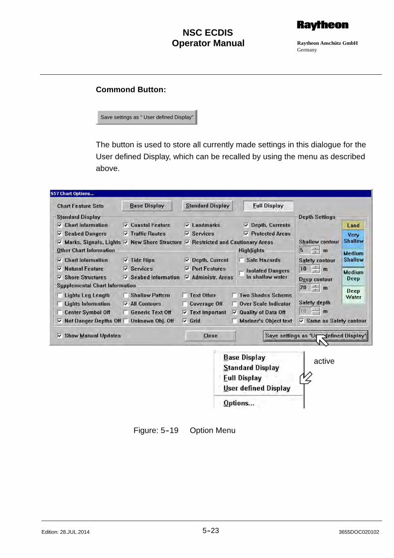
Operator Manual Raytheon Anschütz GmbHGermany
RNSC ECDIS
5--23 3655DOC020102Edition: 28.JUL.2014
Commond Button:
Save settings as “ User defined Display”
The button is used to store all currently made settings in this dialogue for the
User defined Display, which can be recalled by using the menu as described
above.
active
Figure: 5--19 Option Menu
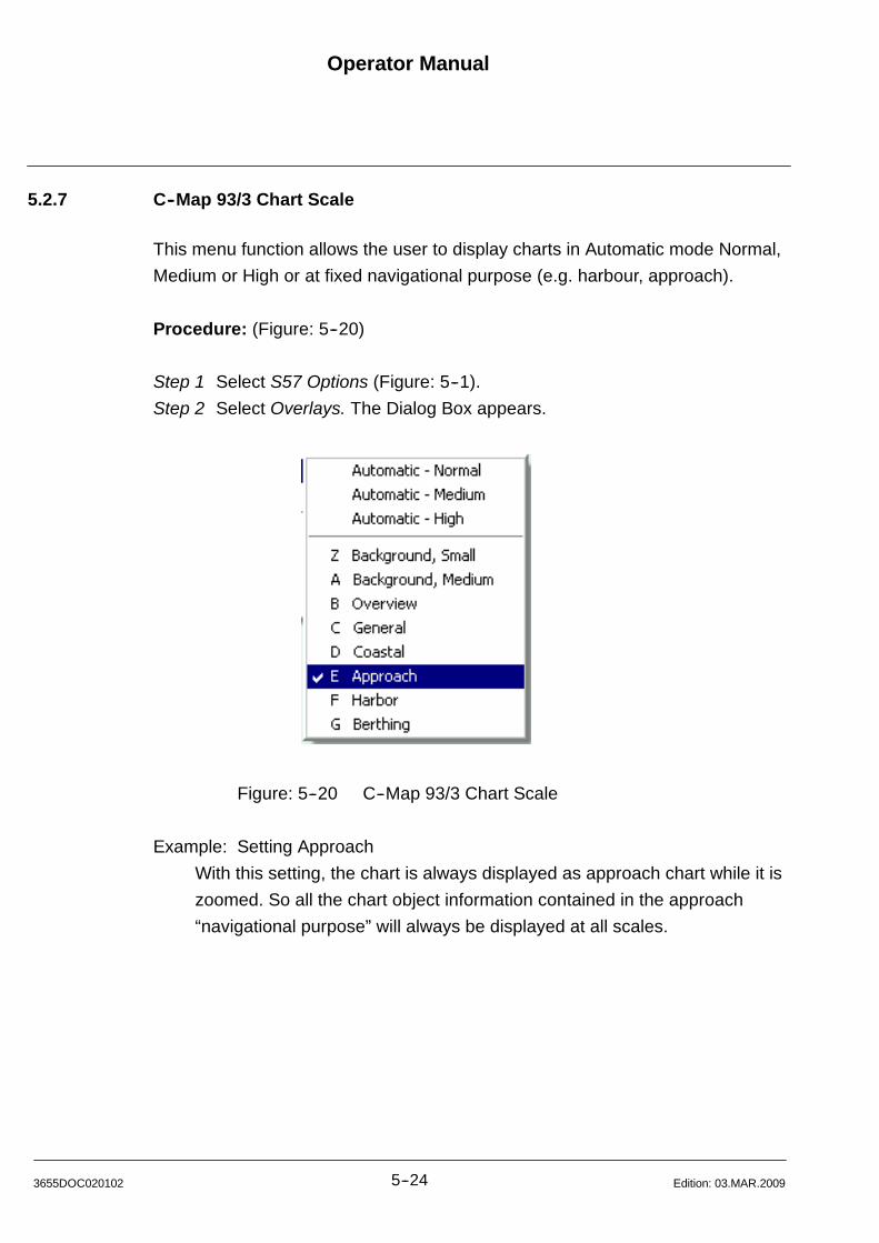
Operator Manual
5--243655DOC020102 Edition: 03.MAR.2009
5.2.7 C--Map 93/3 Chart Scale
This menu function allows the user to display charts in Automatic mode Normal,
Medium or High or at fixed navigational purpose (e.g. harbour, approach).
Procedure: (Figure: 5--20)
Step 1 Select S57 Options (Figure: 5--1).
Step 2 Select Overlays. The Dialog Box appears.
Figure: 5--20 C--Map 93/3 Chart Scale
Example: Setting Approach
With this setting, the chart is always displayed as approach chart while it is
zoomed. So all the chart object information contained in the approach
“navigational purpose” will always be displayed at all scales.
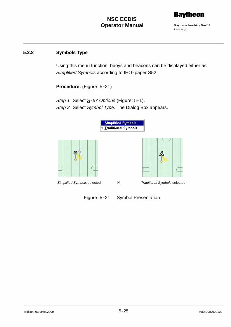
Operator Manual Raytheon Anschütz GmbHGermany
RNSC ECDIS
5--25 3655DOC020102Edition: 03.MAR.2009
5.2.8 Symbols Type
Using this menu function, buoys and beacons can be displayed either as
Simplified Symbols according to IHO--paper S52.
Procedure: (Figure: 5--21)
Step 1 Select S--57 Options (Figure: 5--1).
Step 2 Select Symbol Type. The Dialog Box appears.
Simplified Symbols selected Traditional Symbols selectedor
Figure: 5--21 Symbol Presentation

Operator Manual
5--263655DOC020102 Edition: 03.MAR.2009
5.2.9 Presentation Date (Auto)
This menu function allows the user to find out date--dependant objects in the
chart, such as seasonal buoys, are only to be displayed over a certain period.
Other objects, such as a traffic separation schema, may have a date on which
they are introducted or discontinued.
Procedure: (Figure: 5--22)
Step 1 Select S--57 Options (Figure: 5--1).
Step 2 Select Presentation Date (Auto). The Dialog Box appears.
Figure: 5--22 Presentation Time
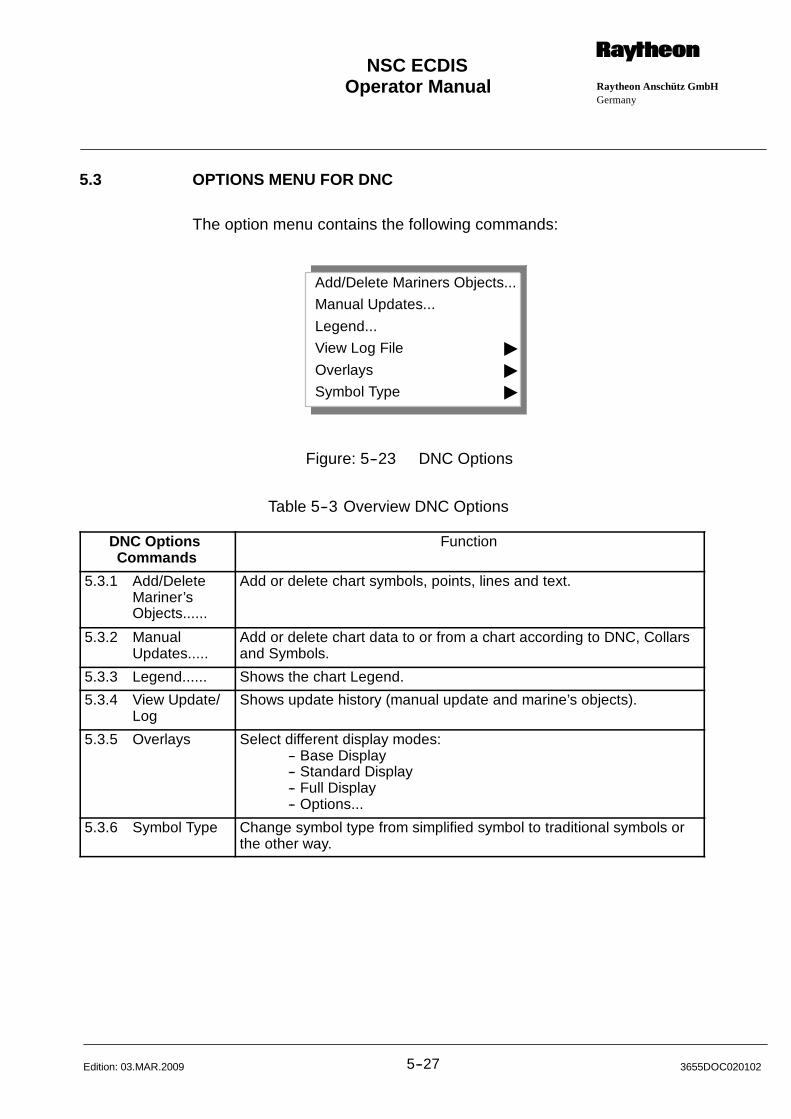
Operator Manual Raytheon Anschütz GmbHGermany
RNSC ECDIS
5--27 3655DOC020102Edition: 03.MAR.2009
5.3 OPTIONS MENU FOR DNC
The option menu contains the following commands:
Add/Delete Mariners Objects...
Manual Updates...
Legend...
View Log File "
Overlays "
Symbol Type "
Figure: 5--23 DNC Options
Table 5--3 Overview DNC Options
DNC OptionsCommands
Function
5.3.1 Add/DeleteMariner’sObjects......
Add or delete chart symbols, points, lines and text.
5.3.2 ManualUpdates.....
Add or delete chart data to or from a chart according to DNC, Collarsand Symbols.
5.3.3 Legend...... Shows the chart Legend.
5.3.4 View Update/Log
Shows update history (manual update and marine’s objects).
5.3.5 Overlays Select different display modes:-- Base Display-- Standard Display-- Full Display-- Options...
5.3.6 Symbol Type Change symbol type from simplified symbol to traditional symbols orthe other way.
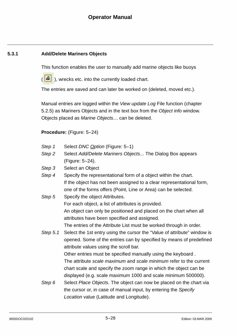
Operator Manual
5--283655DOC020102 Edition: 03.MAR.2009
5.3.1 Add/Delete Mariners Objects
This function enables the user to manually add marine objects like buoys
( ), wrecks etc. into the currently loaded chart.
The entries are saved and can later be worked on (deleted, moved etc.).
Manual entries are logged within the View update Log File function (chapter
5.2.5) as Mariners Objects and in the text box from the Object info window.
Objects placed as Marine Objects can be deleted.
Procedure: (Figure: 5--24)
Step 1 Select DNC Option (Figure: 5--1)
Step 2 Select Add/Delete Mariners Objects... The Dialog Box appears
(Figure: 5--24).
Step 3 Select an Object
Step 4 Specify the representational form of a object within the chart.
If the object has not been assigned to a clear representational form,
one of the forms offers (Point, Line or Area) can be selected.
Step 5 Specify the object Attributes.
For each object, a list of attributes is provided.
An object can only be positioned and placed on the chart when all
attributes have been specified and assigned.
The entries of the Attribute List must be worked through in order.
Step 5.1 Select the 1st entry using the cursor the “Value of attribute” window is
opened. Some of the entries can by specified by means of predefined
attribute values using the scroll bar.
Other entries must be specified manually using the keyboard .
The attribute scale maximum and scale minimum refer to the current
chart scale and specify the zoom range in which the object can be
displayed (e.g. scale maximum 1000 and scale minimum 500000).
Step 6 Select Place Objects. The object can now be placed on the chart via
the cursor or, in case of manual input, by entering the Specify
Location value (Latitude and Longitude).
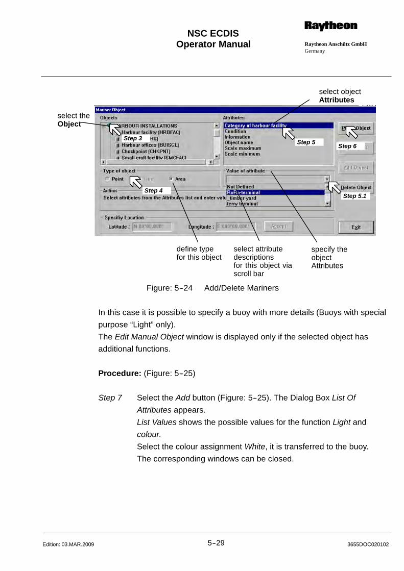
Operator Manual Raytheon Anschütz GmbHGermany
RNSC ECDIS
5--29 3655DOC020102Edition: 03.MAR.2009
select theObject
specify theobjectAttributes
define typefor this object
select objectAttributes
select attributedescriptionsfor this object viascroll bar
Step 3Step 5
Step 5.1Step 4
Step 6
Figure: 5--24 Add/Delete Mariners
In this case it is possible to specify a buoy with more details (Buoys with special
purpose “Light” only).
The Edit Manual Object window is displayed only if the selected object has
additional functions.
Procedure: (Figure: 5--25)
Step 7 Select the Add button (Figure: 5--25). The Dialog Box List Of
Attributes appears.
List Values shows the possible values for the function Light and
colour.
Select the colour assignment White, it is transferred to the buoy.
The corresponding windows can be closed.

Operator Manual
5--303655DOC020102 Edition: 03.MAR.2009
Step 7
Figure: 5--25 Edit Manual Objects dialogue box
By pressing the Close key, the cursor is released for positioning the buoy .
The positioned buoy is displayed within the light cone code within the chart.
Figure: 5--26 Add a special object info
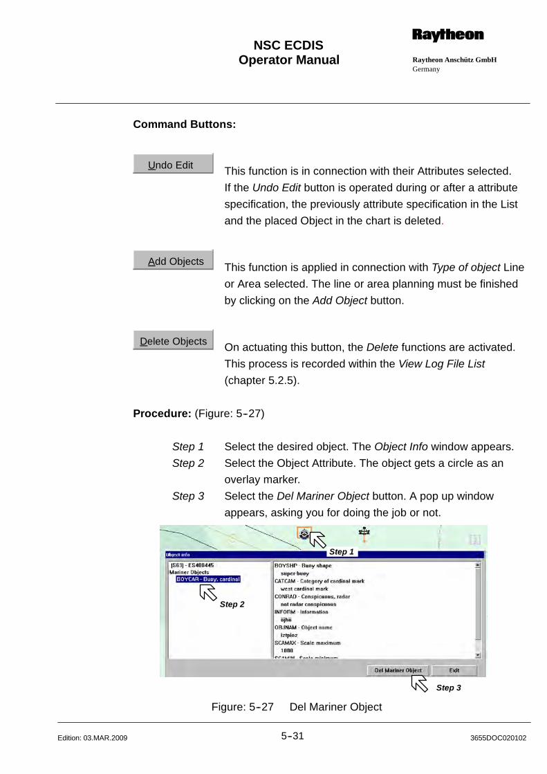
Operator Manual Raytheon Anschütz GmbHGermany
RNSC ECDIS
5--31 3655DOC020102Edition: 03.MAR.2009
Command Buttons:
Undo Edit This function is in connection with their Attributes selected.
If the Undo Edit button is operated during or after a attribute
specification, the previously attribute specification in the List
and the placed Object in the chart is deleted.
Add Objects This function is applied in connection with Type of object Line
or Area selected. The line or area planning must be finished
by clicking on the Add Object button.
Delete Objects On actuating this button, the Delete functions are activated.
This process is recorded within the View Log File List
(chapter 5.2.5).
Procedure: (Figure: 5--27)
Step 1 Select the desired object. The Object Info window appears.
Step 2 Select the Object Attribute. The object gets a circle as an
overlay marker.
Step 3 Select the Del Mariner Object button. A pop up window
appears, asking you for doing the job or not.
Step 1
Step 2
Step 3
Figure: 5--27 Del Mariner Object

Operator Manual
5--323655DOC020102 Edition: 03.MAR.2009
5.3.2 Manual Updates
This menu item is designed for the official manual chart correction (equivalent to
Notes to Mariners for paper charts).
Chart corrections are announced either from the chart manufacturer or regularly
issued Notices to Mariners.
The entries are saved for the sea chart and cannot be visible deleted from their
position.
The object is either deleted or marked as deleted by “ / ” .
The entries can be moved to another place in the chart. Moved entries marked
by “ “ . Moved entries can be deleted from their position.
New Objects can be placed as Marine Updatesmarked by “ “ .
These Objects can be deleted.
The official entries are logged as Manual Updates in the View Log File function
(chapter 5.2.5) and in the text box from the Object info window .
Procedure: (Figure: 5--28)
Step 1 Select DNC Option (Figure: 5--1)
Step 2 Select Manual Updates. The Dialog Box appears (Figure: 5--28).
Step 3 Select an Object
Step 4 Specify the representational form of a object within the chart.
If the object has not been assigned to a clear representational form,
one of the forms offers (Point, Line or Area) can be selected.
Step 5 Specify the object Attributes.
For each object, a list of attributes is provided.
The attribute list has to be modified according the update information
received.
Step 5.1 Select the 1st entry using the cursor the “Value of attribute” window is
opened. Some of the entries can by specified by means of predefined
attribute values using the scroll bar.
Other entries must be specified manually using the keyboard .
The attribute scale maximum and scale minimum refer to the current
chart scale and specify the zoom range in which the object can be
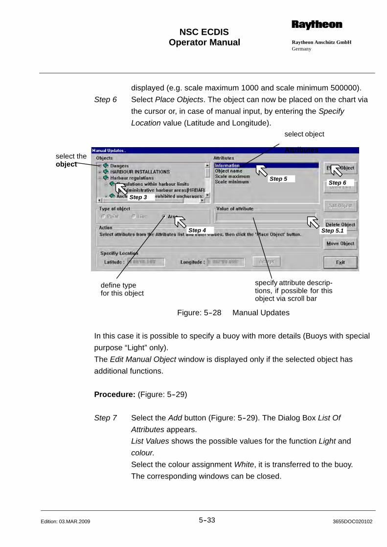
Operator Manual Raytheon Anschütz GmbHGermany
RNSC ECDIS
5--33 3655DOC020102Edition: 03.MAR.2009
displayed (e.g. scale maximum 1000 and scale minimum 500000).
Step 6 Select Place Objects. The object can now be placed on the chart via
the cursor or, in case of manual input, by entering the Specify
Location value (Latitude and Longitude).
select theobject
define typefor this object
select object
Attributes
specify attribute descrip-tions, if possible for thisobject via scroll bar
Step 3
Step 4
Step 5
Step 5.1
Step 6
Figure: 5--28 Manual Updates
In this case it is possible to specify a buoy with more details (Buoys with special
purpose “Light” only).
The Edit Manual Object window is displayed only if the selected object has
additional functions.
Procedure: (Figure: 5--29)
Step 7 Select the Add button (Figure: 5--29). The Dialog Box List Of
Attributes appears.
List Values shows the possible values for the function Light and
colour.
Select the colour assignment White, it is transferred to the buoy.
The corresponding windows can be closed.
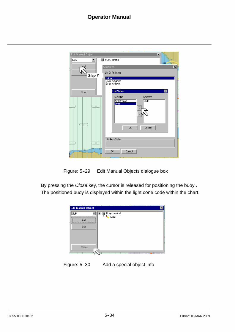
Operator Manual
5--343655DOC020102 Edition: 03.MAR.2009
Step 7
Figure: 5--29 Edit Manual Objects dialogue box
By pressing the Close key, the cursor is released for positioning the buoy .
The positioned buoy is displayed within the light cone code within the chart.
Figure: 5--30 Add a special object info
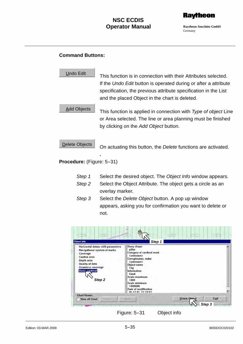
Operator Manual Raytheon Anschütz GmbHGermany
RNSC ECDIS
5--35 3655DOC020102Edition: 03.MAR.2009
Command Buttons:
Undo Edit This function is in connection with their Attributes selected.
If the Undo Edit button is operated during or after a attribute
specification, the previous attribute specification in the List
and the placed Object in the chart is deleted.
Add Objects This function is applied in connection with Type of object Line
or Area selected. The line or area planning must be finished
by clicking on the Add Object button.
Delete Objects On actuating this button, the Delete functions are activated.
.
Procedure: (Figure: 5--31)
Step 1 Select the desired object. The Object Info window appears.
Step 2 Select the Object Attribute. The object gets a circle as an
overlay marker.
Step 3 Select the Delete Object button. A pop up window
appears, asking you for confirmation you want to delete or
not.
Step 1
Step 2
Step 3
Figure: 5--31 Object info
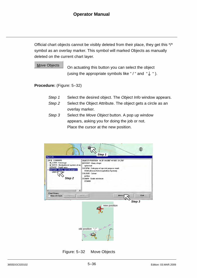
Operator Manual
5--363655DOC020102 Edition: 03.MAR.2009
Official chart objects cannot be visibly deleted from their place, they get this */*
symbol as an overlay marker. This symbol will marked Objects as manually
deleted on the current chart layer.
Move Objects On actuating this button you can select the object
(using the appropriate symbols like “ / “ and “ “ ).
Procedure: (Figure: 5--32)
Step 1 Select the desired object. The Object Info window appears.
Step 2 Select the Object Attribute. The object gets a circle as an
overlay marker.
Step 3 Select the Move Object button. A pop up window
appears, asking you for doing the job or not.
Place the cursor at the new position.
Step 1
Step 2
Step 3new position
old position “ / “
Figure: 5--32 Move Objects
Operator Manual Raytheon Anschütz GmbHGermany
RNSC ECDIS
5--37 3655DOC020102Edition: 03.MAR.2009
Chart Viewer:
DNC charts are made up of several scale ranges. The information extent of the
scale ranges varies and is determined via the penetration depth (zoom in/out).
If an object is now deleted or inserted in a scale range, this action is restricted
only to this scale range.
Previous or subsequent scale ranges are not considered in this process.
This means that deleted objects are still displayed there, new objects are
missing.
In order to avoid this missing information, the object information of the scale
ranges must be updated after deletion or addition.
After the deletion/insertion of an object, the following steps are recommended.
Select View all chart, it will display the updated object at the first navigation
purpose where this object is available centred on the chart.
The displayed dataset will be automatically be presented at the smallest scale
available.
At the same time tree list box and the Delete Object button will be enabled.
Press on the Next button to move to next navigation purpose (e.g. harbour).
Now you can navigate through all chart scales using the Next or Prev button.
If there is no smaller scale containing the object then the Next button will be
disabled.
If you are at most detailed navigation purpose then Prev button will be disable.
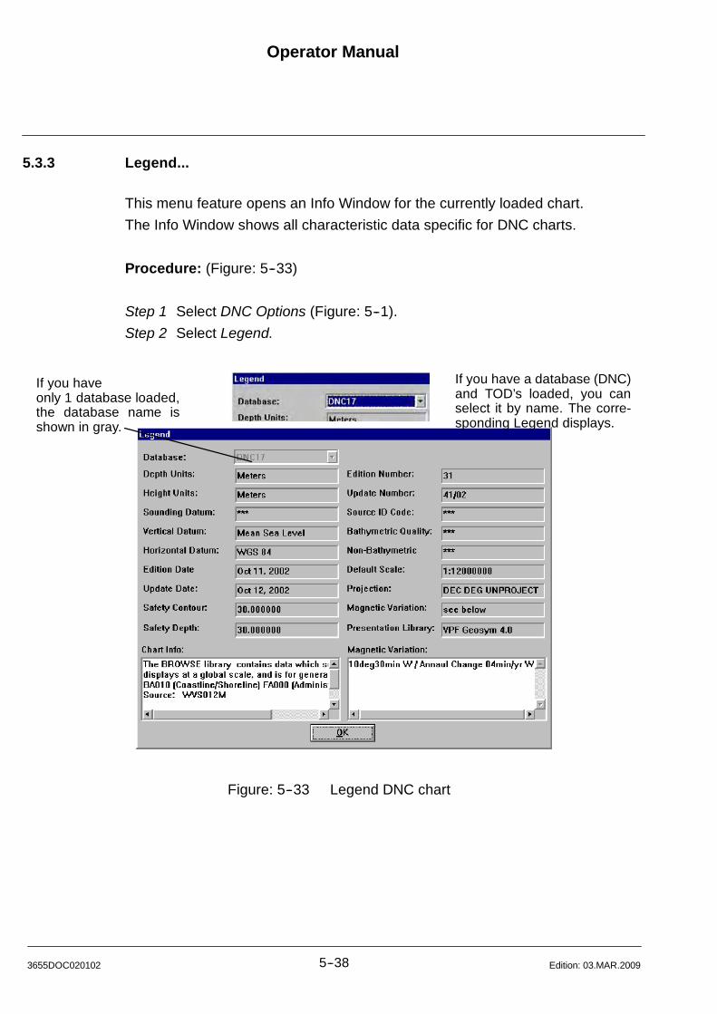
Operator Manual
5--383655DOC020102 Edition: 03.MAR.2009
5.3.3 Legend...
This menu feature opens an Info Window for the currently loaded chart.
The Info Window shows all characteristic data specific for DNC charts.
Procedure: (Figure: 5--33)
Step 1 Select DNC Options (Figure: 5--1).
Step 2 Select Legend.
If you haveonly 1 database loaded,the database name isshown in gray.
If you have a database (DNC)and TOD’s loaded, you canselect it by name. The corre-sponding Legend displays.
Figure: 5--33 Legend DNC chart
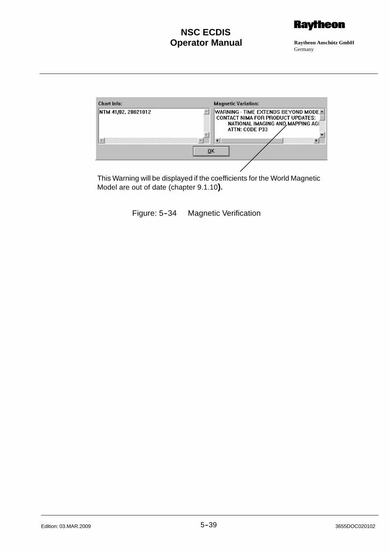
Operator Manual Raytheon Anschütz GmbHGermany
RNSC ECDIS
5--39 3655DOC020102Edition: 03.MAR.2009
This Warning will be displayed if the coefficients for the World MagneticModel are out of date (chapter 9.1.10).
Figure: 5--34 Magnetic Verification
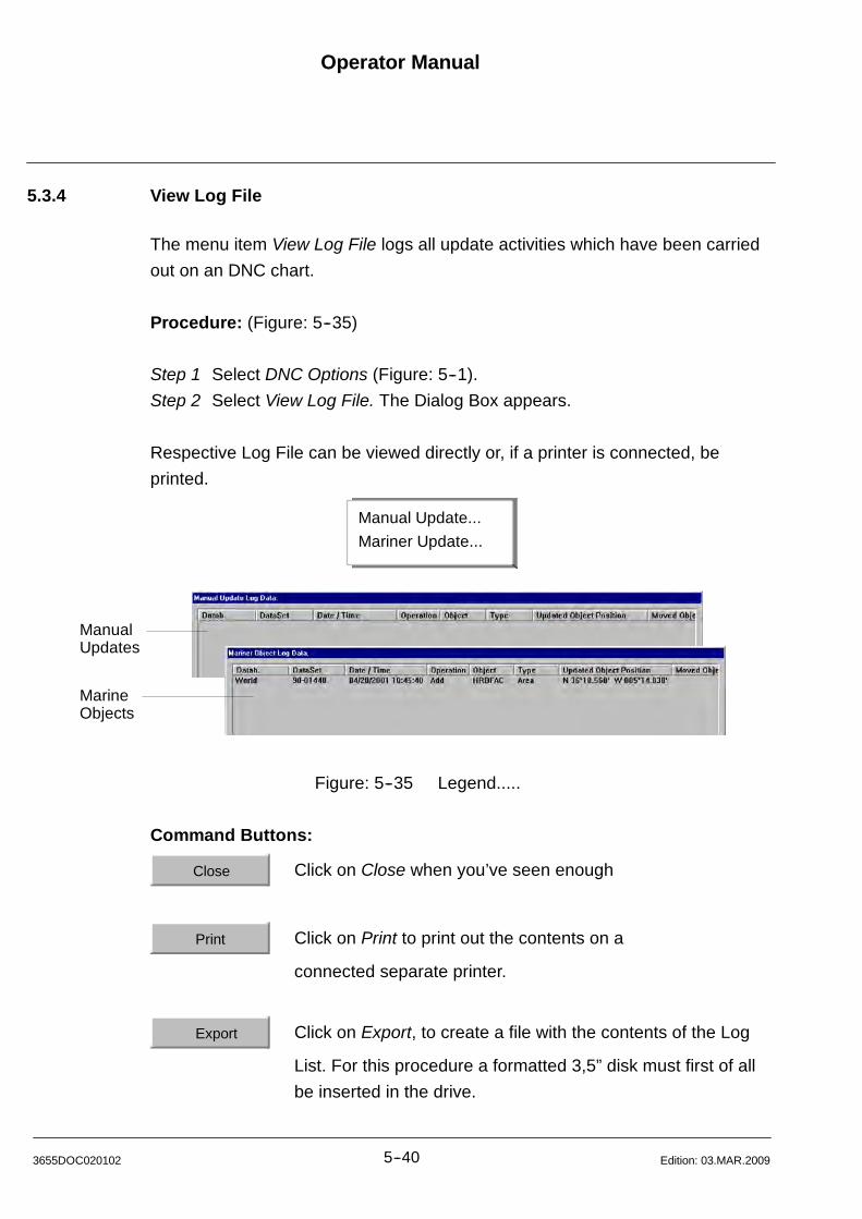
Operator Manual
5--403655DOC020102 Edition: 03.MAR.2009
5.3.4 View Log File
The menu item View Log File logs all update activities which have been carried
out on an DNC chart.
Procedure: (Figure: 5--35)
Step 1 Select DNC Options (Figure: 5--1).
Step 2 Select View Log File. The Dialog Box appears.
Respective Log File can be viewed directly or, if a printer is connected, be
printed.
ManualUpdates
MarineObjects
Manual Update...
Mariner Update...
Figure: 5--35 Legend.....
Command Buttons:
Close Click on Close when you’ve seen enough
Print Click on Print to print out the contents on a
connected separate printer.
Export Click on Export, to create a file with the contents of the Log
List. For this procedure a formatted 3,5” disk must first of all
be inserted in the drive.
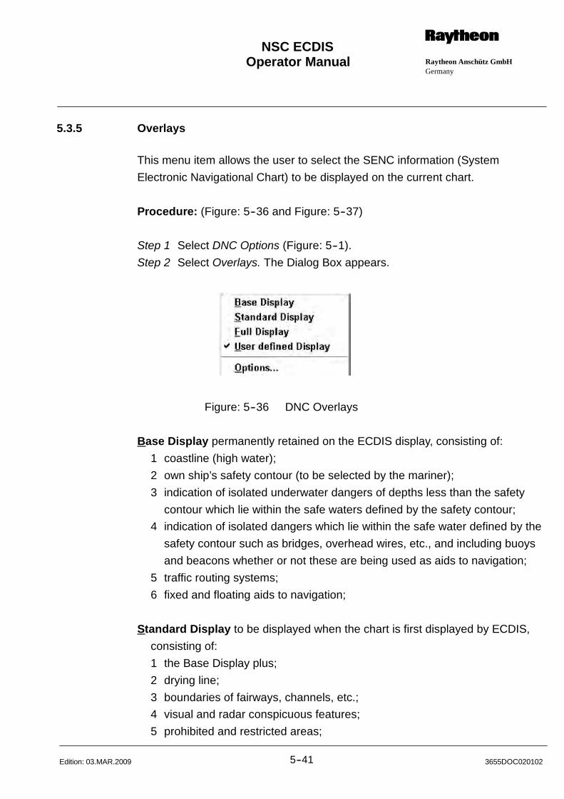
Operator Manual Raytheon Anschütz GmbHGermany
RNSC ECDIS
5--41 3655DOC020102Edition: 03.MAR.2009
5.3.5 Overlays
This menu item allows the user to select the SENC information (System
Electronic Navigational Chart) to be displayed on the current chart.
Procedure: (Figure: 5--36 and Figure: 5--37)
Step 1 Select DNC Options (Figure: 5--1).
Step 2 Select Overlays. The Dialog Box appears.
Figure: 5--36 DNC Overlays
Base Display permanently retained on the ECDIS display, consisting of:
1 coastline (high water);
2 own ship’s safety contour (to be selected by the mariner);
3 indication of isolated underwater dangers of depths less than the safety
contour which lie within the safe waters defined by the safety contour;
4 indication of isolated dangers which lie within the safe water defined by the
safety contour such as bridges, overhead wires, etc., and including buoys
and beacons whether or not these are being used as aids to navigation;
5 traffic routing systems;
6 fixed and floating aids to navigation;
Standard Display to be displayed when the chart is first displayed by ECDIS,
consisting of:
1 the Base Display plus;
2 drying line;
3 boundaries of fairways, channels, etc.;
4 visual and radar conspicuous features;
5 prohibited and restricted areas;
Operator Manual
5--423655DOC020102 Edition: 03.MAR.2009
6 chart scale boundaries;
7 indication of cautionary notes;
Full Display all other information which is not part of the Standard Display, for
example:
1 spot soundings;
2 submarine cables and pipelines;
3 ferry routes;
4 contents of cautionary notes;
5 graticule;
6 place names;
DNC Chart Options....
With this menu item, additional display information can be turned on or off by
pressing the corresponding check boxes. The availability of the check box
groups depends on the pre--selected chart feature set (Base Display / Standard
Display/ Full Display).
The values for 3 different depth contour lines and the safety depth can be set.
Routes and the Antigrounding Searchlight are checked against the Safety
Contour. The safety Contour line is displayed in any mode. The other contour
lines are only used for visual distinction of different depth areas.
The Safety depth is used to distinguish safe and dangerous spot soundings. The
value of the Safety depth can be linked to the Safety contour by using the
corresponding check box.
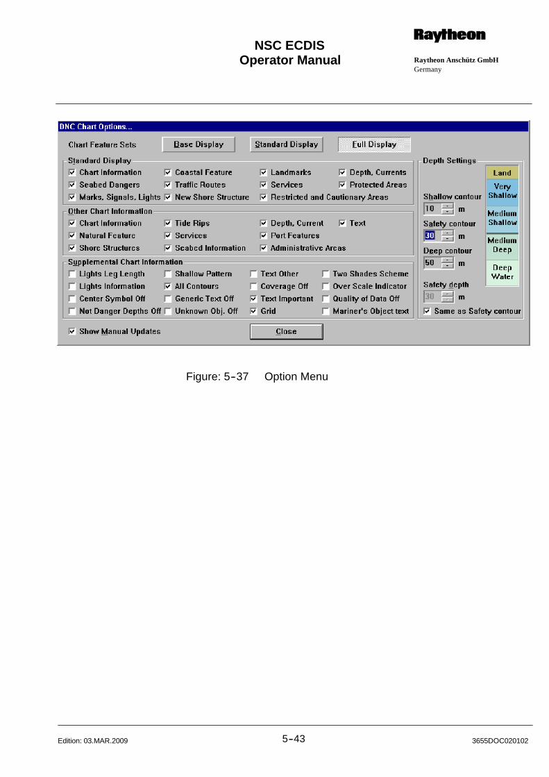
Operator Manual Raytheon Anschütz GmbHGermany
RNSC ECDIS
5--43 3655DOC020102Edition: 03.MAR.2009
Figure: 5--37 Option Menu
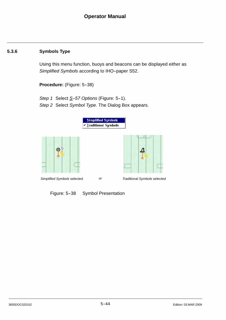
Operator Manual
5--443655DOC020102 Edition: 03.MAR.2009
5.3.6 Symbols Type
Using this menu function, buoys and beacons can be displayed either as
Simplified Symbols according to IHO--paper S52.
Procedure: (Figure: 5--38)
Step 1 Select S--57 Options (Figure: 5--1).
Step 2 Select Symbol Type. The Dialog Box appears.
Simplified Symbols selected Traditional Symbols selectedor
Figure: 5--38 Symbol Presentation
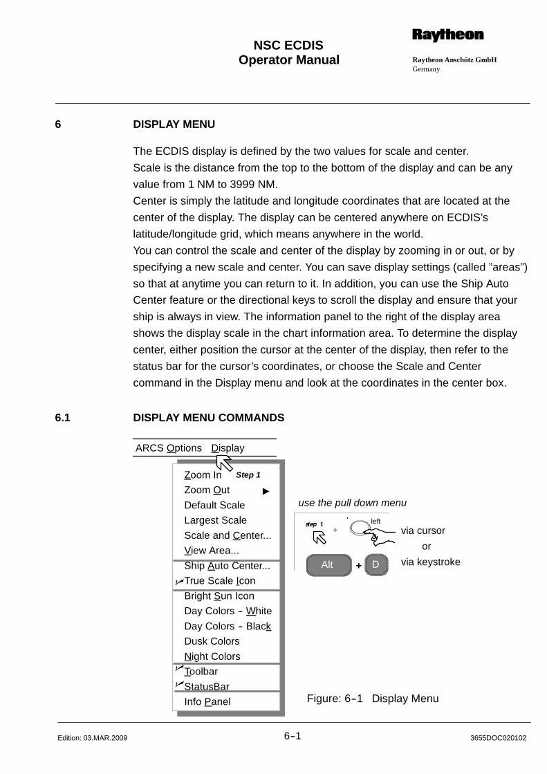
Operator Manual Raytheon Anschütz GmbHGermany
RNSC ECDIS
6--1 3655DOC020102Edition: 03.MAR.2009
6 DISPLAY MENU
The ECDIS display is defined by the two values for scale and center.
Scale is the distance from the top to the bottom of the display and can be any
value from 1 NM to 3999 NM.
Center is simply the latitude and longitude coordinates that are located at the
center of the display. The display can be centered anywhere on ECDIS’s
latitude/longitude grid, which means anywhere in the world.
You can control the scale and center of the display by zooming in or out, or by
specifying a new scale and center. You can save display settings (called ”areas”)
so that at anytime you can return to it. In addition, you can use the Ship Auto
Center feature or the directional keys to scroll the display and ensure that your
ship is always in view. The information panel to the right of the display area
shows the display scale in the chart information area. To determine the display
center, either position the cursor at the center of the display, then refer to the
status bar for the cursor’s coordinates, or choose the Scale and Center
command in the Display menu and look at the coordinates in the center box.
6.1 DISPLAY MENU COMMANDS
Alt D
via cursor
via keystroke
or
+
use the pull down menu
Zoom In
Zoom Out "
Default Scale
Largest Scale
Scale and Center...
View Area...
Ship Auto Center...
True Scale Icon
Bright Sun Icon
Day Colors -- White
Day Colors -- Black
Dusk Colors
Night Colors
Toolbar
StatusBar
Info Panel
n
n
n
ARCS Options Display
Step 1
Figure: 6--1 Display Menu
left
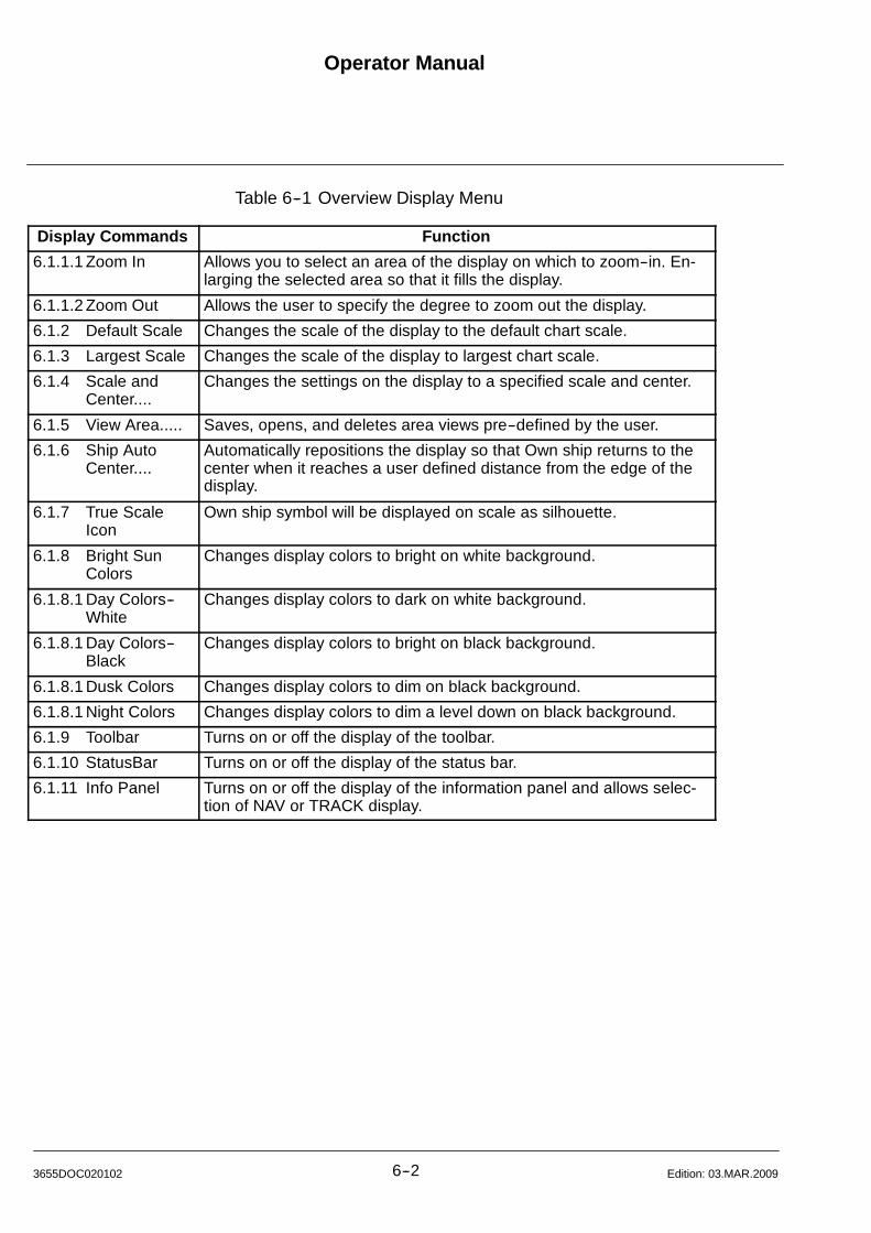
Operator Manual
6--23655DOC020102 Edition: 03.MAR.2009
Table 6--1 Overview Display Menu
Display Commands Function
6.1.1.1 Zoom In Allows you to select an area of the display on which to zoom--in. En-larging the selected area so that it fills the display.
6.1.1.2 Zoom Out Allows the user to specify the degree to zoom out the display.
6.1.2 Default Scale Changes the scale of the display to the default chart scale.
6.1.3 Largest Scale Changes the scale of the display to largest chart scale.
6.1.4 Scale andCenter....
Changes the settings on the display to a specified scale and center.
6.1.5 View Area..... Saves, opens, and deletes area views pre--defined by the user.
6.1.6 Ship AutoCenter....
Automatically repositions the display so that Own ship returns to thecenter when it reaches a user defined distance from the edge of thedisplay.
6.1.7 True ScaleIcon
Own ship symbol will be displayed on scale as silhouette.
6.1.8 Bright SunColors
Changes display colors to bright on white background.
6.1.8.1 Day Colors--White
Changes display colors to dark on white background.
6.1.8.1 Day Colors--Black
Changes display colors to bright on black background.
6.1.8.1 Dusk Colors Changes display colors to dim on black background.
6.1.8.1 Night Colors Changes display colors to dim a level down on black background.
6.1.9 Toolbar Turns on or off the display of the toolbar.
6.1.10 StatusBar Turns on or off the display of the status bar.
6.1.11 Info Panel Turns on or off the display of the information panel and allows selec-tion of NAV or TRACK display.
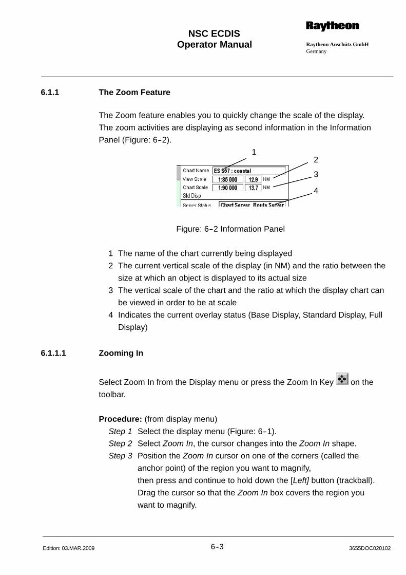
Operator Manual Raytheon Anschütz GmbHGermany
RNSC ECDIS
6--3 3655DOC020102Edition: 03.MAR.2009
6.1.1 The Zoom Feature
The Zoom feature enables you to quickly change the scale of the display.
The zoom activities are displaying as second information in the Information
Panel (Figure: 6--2).
12
3
4
Figure: 6--2 Information Panel
1 The name of the chart currently being displayed
2 The current vertical scale of the display (in NM) and the ratio between the
size at which an object is displayed to its actual size
3 The vertical scale of the chart and the ratio at which the display chart can
be viewed in order to be at scale
4 Indicates the current overlay status (Base Display, Standard Display, Full
Display)
6.1.1.1 Zooming In
Select Zoom In from the Display menu or press the Zoom In Key on the
toolbar.
Procedure: (from display menu)
Step 1 Select the display menu (Figure: 6--1).
Step 2 Select Zoom In, the cursor changes into the Zoom In shape.
Step 3 Position the Zoom In cursor on one of the corners (called the
anchor point) of the region you want to magnify,
then press and continue to hold down the [Left] button (trackball).
Drag the cursor so that the Zoom In box covers the region you
want to magnify.
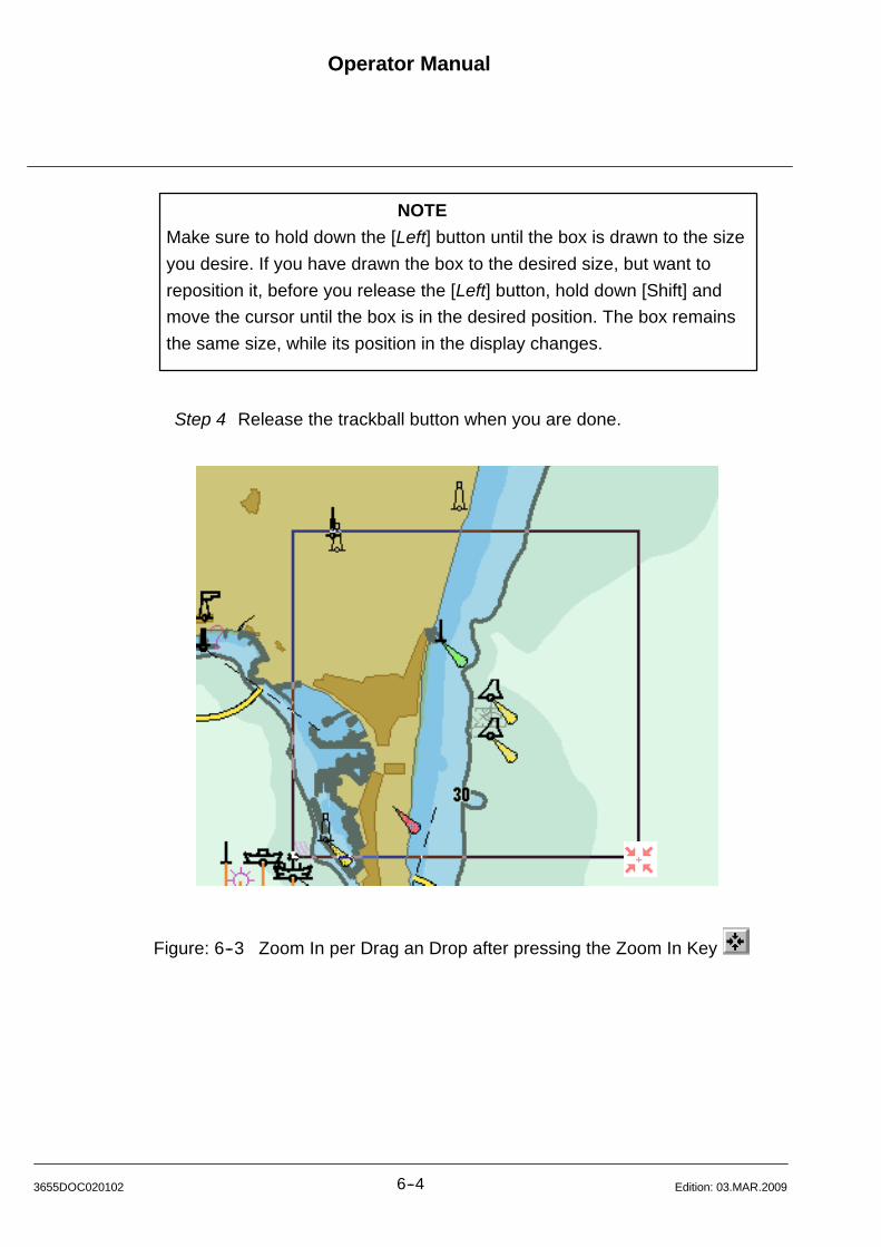
Operator Manual
6--43655DOC020102 Edition: 03.MAR.2009
NOTE
Make sure to hold down the [Left] button until the box is drawn to the size
you desire. If you have drawn the box to the desired size, but want to
reposition it, before you release the [Left] button, hold down [Shift] and
move the cursor until the box is in the desired position. The box remains
the same size, while its position in the display changes.
Step 4 Release the trackball button when you are done.
Figure: 6--3 Zoom In per Drag an Drop after pressing the Zoom In Key
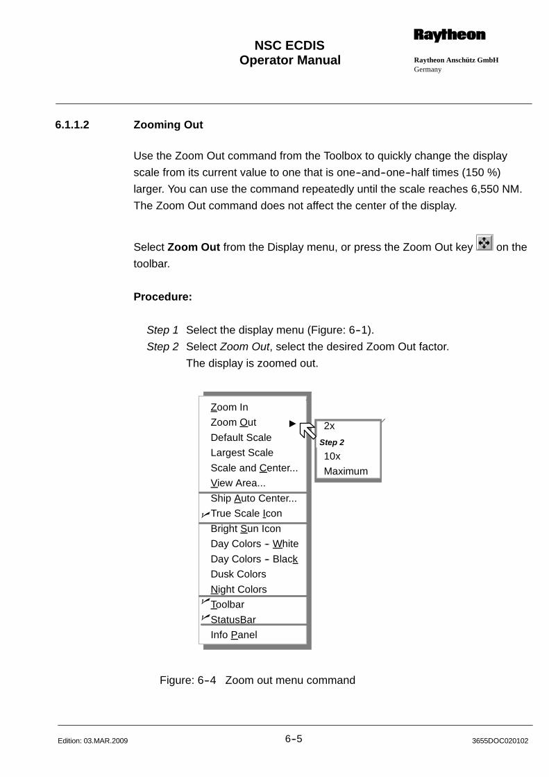
Operator Manual Raytheon Anschütz GmbHGermany
RNSC ECDIS
6--5 3655DOC020102Edition: 03.MAR.2009
6.1.1.2 Zooming Out
Use the Zoom Out command from the Toolbox to quickly change the display
scale from its current value to one that is one--and--one--half times (150 %)
larger. You can use the command repeatedly until the scale reaches 6,550 NM.
The Zoom Out command does not affect the center of the display.
Select Zoom Out from the Display menu, or press the Zoom Out key on the
toolbar.
Procedure:
Step 1 Select the display menu (Figure: 6--1).
Step 2 Select Zoom Out, select the desired Zoom Out factor.
The display is zoomed out.
2x
5x
10x
Maximum
Zoom In
Zoom Out "
Default Scale
Largest Scale
Scale and Center...
View Area...
Ship Auto Center...
True Scale Icon
Bright Sun Icon
Day Colors -- White
Day Colors -- Black
Dusk Colors
Night Colors
Toolbar
StatusBar
Info Panel
n
n
n
Step 2
Figure: 6--4 Zoom out menu command
Operator Manual
6--63655DOC020102 Edition: 03.MAR.2009
6.1.2 Default Scale
Display the current chart at the default scale.
6.1.3 Largest Scale
Load and display the chart with the largest available scale at the current display
position.
6.1.4 Scale and Center Command
When you want to center the display on a specific location or change the scale
to a particular value, use the Scale and Center command. When the command is
selected, the ECDIS displays the Scale and Center dialog box.
6.1.4.1 Change the Scale and Center of the Display
Procedure:
Step 1 Select the display menu (Figure: 6--1).
Step 2 Select Scale and Center. The dialog box appears.
The current display center appears in the Latitude and Longitude
boxes and the current scale appears at the bottom of the scale area.
Unit of measure is NM.
Step 3 To change the scale of the display, either click on the desired scale,
or, click in the text box, then type the desired scale, or, use the scroll
bar to change the value in the text box.
Step 4 To change the center of the display use the Latitude and
Longitude boxes to enter the desired coordinates.
Step 5 Press on OK, or to reset the scale and center back to the
value at which you opened the dialog box,by clicking on Reset.
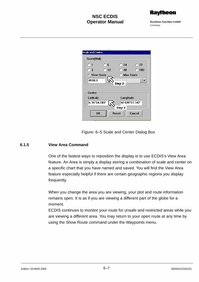
Operator Manual Raytheon Anschütz GmbHGermany
RNSC ECDIS
6--7 3655DOC020102Edition: 03.MAR.2009
Step 3Step 3
Step 4
Step 3Step 3
Figure: 6--5 Scale and Center Dialog Box
6.1.5 View Area Command
One of the fastest ways to reposition the display is to use ECDIS’s View Area
feature. An Area is simply a display storing a combination of scale and center on
a specific chart that you have named and saved. You will find the View Area
feature especially helpful if there are certain geographic regions you display
frequently.
When you change the area you are viewing, your plot and route information
remains open. It is as if you are viewing a different part of the globe for a
moment.
ECDIS continues to monitor your route for unsafe and restricted areas while you
are viewing a different area. You may return to your open route at any time by
using the Show Route command under the Waypoints menu.
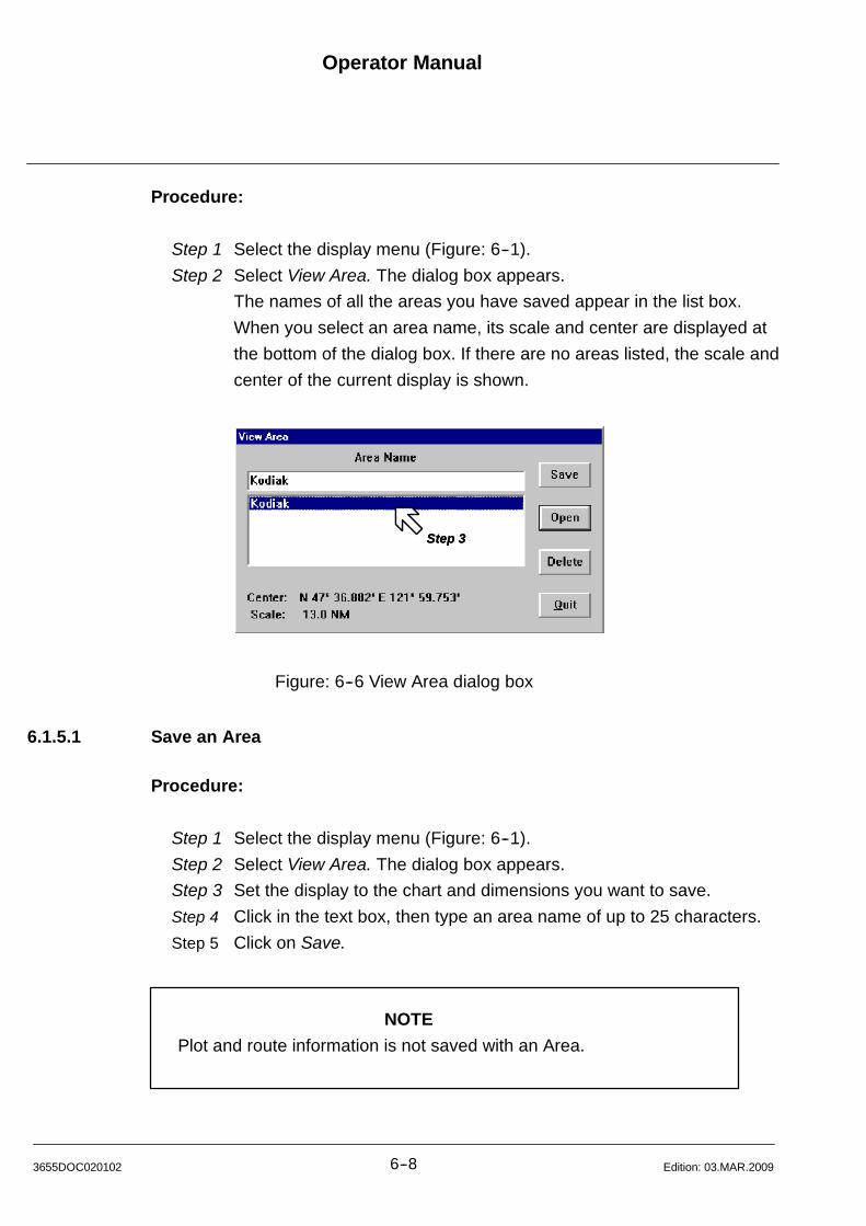
Operator Manual
6--83655DOC020102 Edition: 03.MAR.2009
Procedure:
Step 1 Select the display menu (Figure: 6--1).
Step 2 Select View Area. The dialog box appears.
The names of all the areas you have saved appear in the list box.
When you select an area name, its scale and center are displayed at
the bottom of the dialog box. If there are no areas listed, the scale and
center of the current display is shown.
Step 3Step 3
Figure: 6--6 View Area dialog box
6.1.5.1 Save an Area
Procedure:
Step 1 Select the display menu (Figure: 6--1).
Step 2 Select View Area. The dialog box appears.
Step 3 Set the display to the chart and dimensions you want to save.
Step 4 Click in the text box, then type an area name of up to 25 characters.
Step 5 Click on Save.
NOTE
Plot and route information is not saved with an Area.
Operator Manual Raytheon Anschütz GmbHGermany
RNSC ECDIS
6--9 3655DOC020102Edition: 03.MAR.2009
6.1.5.2 Open an Area
Procedure:
Step 1 Select the display menu (Figure: 6--1).
Step 2 Select View Area. The dialog box appears.
Step 3 Click on the name of the area you want to open. The area name
appears in the text box and its scale and center appear below the list
box.
Step 4 Click on Open.
6.1.5.3 Delete an Area
Procedure:
Step 1 Select the display menu (Figure: 6--1).
Step 2 Select View Area. The dialog box appears.
Step 3 Click on the name of the area you want to delete.
Step 4 Click on Delete.
Operator Manual
6--103655DOC020102 Edition: 03.MAR.2009
6.1.6 Keeping Your Ship in the Display Area (Ship Auto Center)
When you turn on the Auto Center feature, ECDIS automatically moves the
displayed chart area so that your ship is always in view. When your ship reaches
a point near the edge of the display (that you determine), ECDIS automatically
recalculates the center of the display, then re--centers it so that your ship is at its
center. If Ship Auto Center is off and your ship travels outside the display,
ECDIS continues tracking your ship; you just can’t see it. To locate your ship,
simply turn on Ship Auto Center, or click the Center on Ship button on the
toolbar. Ship Auto Center automatically turns off if you scroll the display 3 times
in any direction.
6.1.6.1 Turning ON or OFF Auto Center
Procedure:
Step 1 Select the display menu (Figure: 6--1).
Step 2 Select Auto Center. The dialog box appears (Figure: 6--7).
Step 3 Click inside the Auto Center Enabled check box.
Allows the ship motion by using a value from 1 ..... 30% before next
redraw.
When the ship has traveled across e.g. 5% of the screen ECDIS
will recenter the display.
Off Center allows the ship displaying by using a value from 0
(display center) ...70% of the display.
Step 4 Select Use Toolbar button to enable / disable Auto Center, the Ship
Auto Center function may be switched on.
Otherwise the toolbar button will only center the ship on the chart
without effecting the Auto Center function.
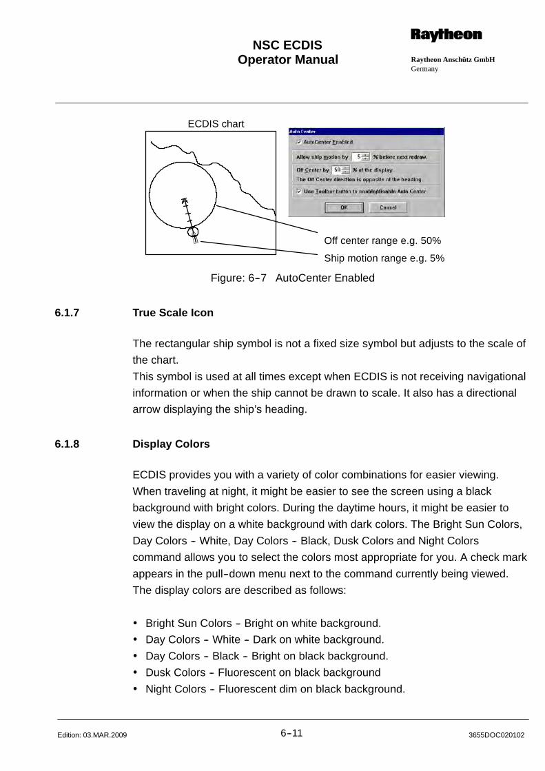
Operator Manual Raytheon Anschütz GmbHGermany
RNSC ECDIS
6--11 3655DOC020102Edition: 03.MAR.2009
Off center range e.g. 50%
Ship motion range e.g. 5%
ECDIS chart
Figure: 6--7 AutoCenter Enabled
6.1.7 True Scale Icon
The rectangular ship symbol is not a fixed size symbol but adjusts to the scale of
the chart.
This symbol is used at all times except when ECDIS is not receiving navigational
information or when the ship cannot be drawn to scale. It also has a directional
arrow displaying the ship’s heading.
6.1.8 Display Colors
ECDIS provides you with a variety of color combinations for easier viewing.
When traveling at night, it might be easier to see the screen using a black
background with bright colors. During the daytime hours, it might be easier to
view the display on a white background with dark colors. The Bright Sun Colors,
Day Colors -- White, Day Colors -- Black, Dusk Colors and Night Colors
command allows you to select the colors most appropriate for you. A check mark
appears in the pull--down menu next to the command currently being viewed.
The display colors are described as follows:
Bright Sun Colors -- Bright on white background.
Day Colors -- White -- Dark on white background.
Day Colors -- Black -- Bright on black background.
Dusk Colors -- Fluorescent on black background
Night Colors -- Fluorescent dim on black background.
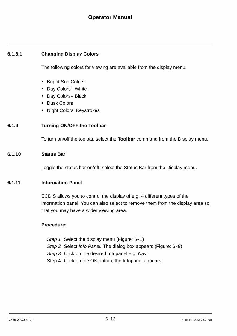
Operator Manual
6--123655DOC020102 Edition: 03.MAR.2009
6.1.8.1 Changing Display Colors
The following colors for viewing are available from the display menu.
Bright Sun Colors,
Day Colors-- White
Day Colors-- Black
Dusk Colors
Night Colors, Keystrokes
6.1.9 Turning ON/OFF the Toolbar
To turn on/off the toolbar, select the Toolbar command from the Display menu.
6.1.10 Status Bar
Toggle the status bar on/off, select the Status Bar from the Display menu.
6.1.11 Information Panel
ECDIS allows you to control the display of e.g. 4 different types of the
information panel. You can also select to remove them from the display area so
that you may have a wider viewing area.
Procedure:
Step 1 Select the display menu (Figure: 6--1)
Step 2 Select Info Panel. The dialog box appears (Figure: 6--8)
Step 3 Click on the desired Infopanel e.g. Nav.
Step 4 Click on the OK button, the Infopanel appears.
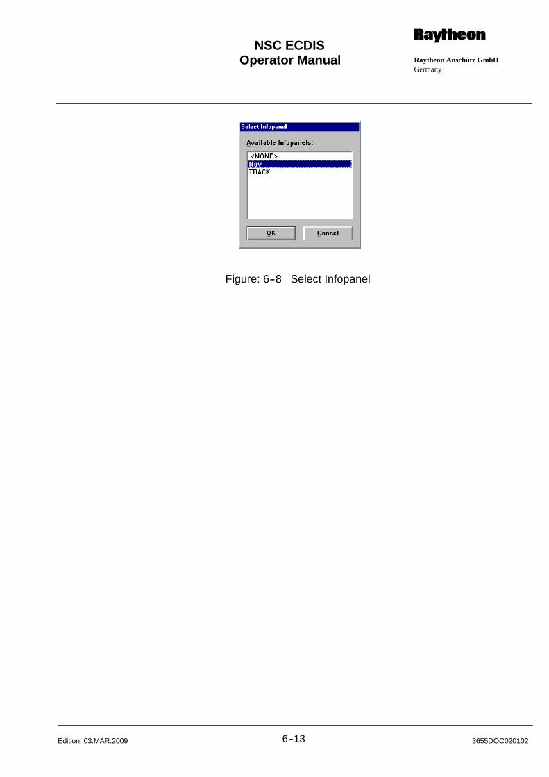
Operator Manual Raytheon Anschütz GmbHGermany
RNSC ECDIS
6--13 3655DOC020102Edition: 03.MAR.2009
Figure: 6--8 Select Infopanel

Operator Manual
6--143655DOC020102 Edition: 03.MAR.2009
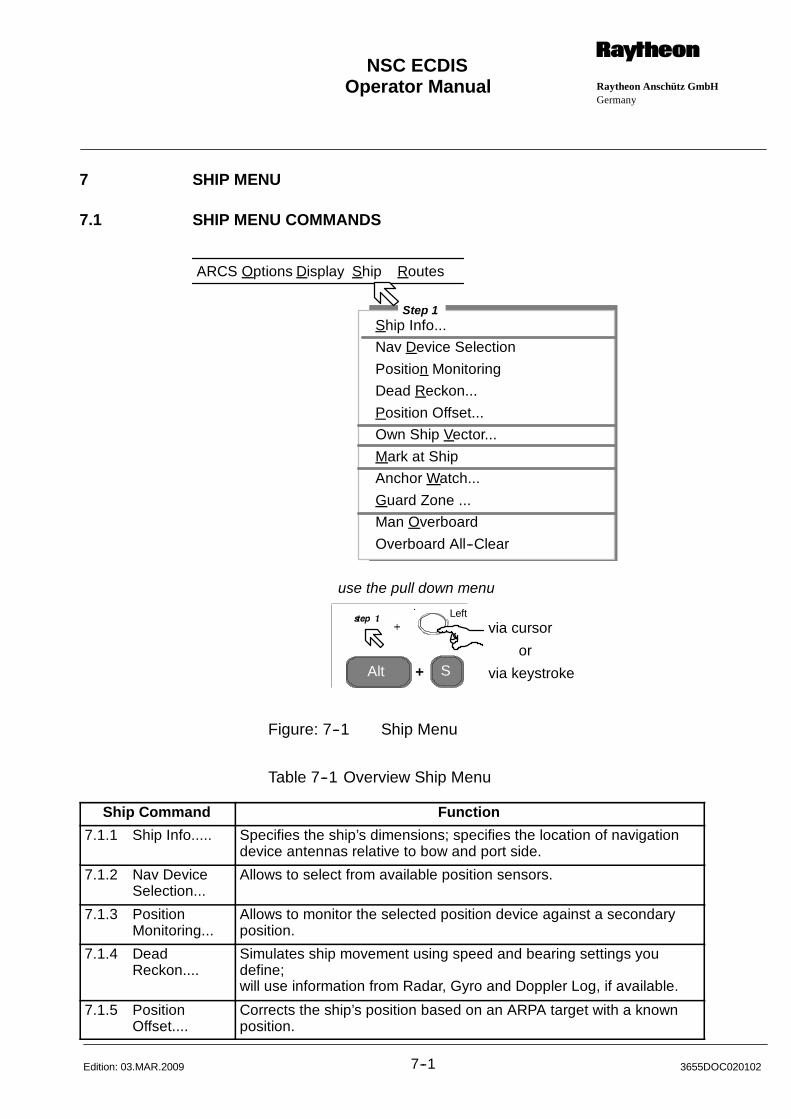
Operator Manual Raytheon Anschütz GmbHGermany
RNSC ECDIS
7--1 3655DOC020102Edition: 03.MAR.2009
7 SHIP MENU
7.1 SHIP MENU COMMANDS
Alt S+
Ship Info...
Nav Device Selection
Position Monitoring
Dead Reckon...
Position Offset...
Own Ship Vector...
Mark at Ship
Anchor Watch...
Guard Zone ...
Man Overboard
Overboard All--Clear
via cursor
via keystroke
or
use the pull down menu
ARCS Options Display
Step 1
Ship Routes
Left
Figure: 7--1 Ship Menu
Table 7--1 Overview Ship Menu
Ship Command Function
7.1.1 Ship Info..... Specifies the ship’s dimensions; specifies the location of navigationdevice antennas relative to bow and port side.
7.1.2 Nav DeviceSelection...
Allows to select from available position sensors.
7.1.3 PositionMonitoring...
Allows to monitor the selected position device against a secondaryposition.
7.1.4 DeadReckon....
Simulates ship movement using speed and bearing settings youdefine;will use information from Radar, Gyro and Doppler Log, if available.
7.1.5 PositionOffset....
Corrects the ship’s position based on an ARPA target with a knownposition.

Operator Manual
7--23655DOC020102 Edition: 03.MAR.2009
Ship Command Function
7.1.6 Own ShipVector....
Turn on or off course vector, heading line or antigrounding search-light.
7.1.7 Mark at Ship Place a ship mark with a time level at the ship’s position.
7.1.8 AnchorWatch....
Allows Pathfinder/ST ECDIS to monitor the drift of the ship whileanchored.
7.1.10 Guard Zone... Place an alarm zone around Own Ship to monitor intruding ARPA tar-gets at a defined distance.
7.1.10 Man Over--board.
Turn off the autopilot, places a mark at ship’s location, (and sounds a(general) ship alarm when activated). May be cancelled.
7.1.11 OverboardAll--Clear
Clear the man overboard alarm and posts an “All Clear” entry to theEvent Log.
Operator Manual Raytheon Anschütz GmbHGermany
RNSC ECDIS
7--3 3655DOC020102Edition: 03.MAR.2009
7.1.1 Ship Info Command
ECDIS provides a feature that increases the accuracy of the display of naviga-
tional data. The Ship Info command is where you enter the dimensions of the
vessel, as well as specify where the navigational antennas are located.
ECDIS uses the entered information in many ways. First, it draws the ship sym-
bol so that it is proportional to the specified vessel size. More importantly, be-
cause ECDIS knows where on the ship the antennas are located, it can offset
the ship symbol from that point, giving you a more accurate representation of
your position relative to other objects. In addition, ECDIS uses the information to
more accurately draw tracks and the course line, as well as to calculate the nec-
essary safety alarms.
Procedure: (Figure: 7--2)
Step 1 Select the ship menu (Figure: 7--1).
Step 2 Select Ship Info... The dialog box appears.
NOTE
Only Safety Contour and Safety Depth can be changed. All other values
can only be modified in service mode.

Operator Manual
7--43655DOC020102 Edition: 03.MAR.2009
Figure: 7--2 Ship Info dialog box
Operator Manual Raytheon Anschütz GmbHGermany
RNSC ECDIS
7--5 3655DOC020102Edition: 03.MAR.2009
7.1.2 Selecting the Navigation Devices (only available in the Service Mode)
Use the Nav Device Selection command to select from the type(s) of navigation
positioning device(s) you have integrated with ECDIS: GPS, Loran--C, Transit or
Syledis (column “Use”).
We recommend that you select Dead Reckon as an available ”device”. In the
event that the selected navigation device fails, your ship’s course is simulated
using ECDIS’s Dead Reckon feature (chapter 7.1.4).
If you have integrated ECDIS with a device not listed, use the Custom ID1 and
Custom ID2 boxes to enter a two letter code for the device. The code must
match the one that appears as the NMEA talker ID in the data sentences output
by the device. Please see ”Navigation (Talker) Devices ID (ECDIS)”
(chapter 12.1.1.1).
ECDIS can use data from only one navigation device at a time. You have to se-
lect from the available devices, which type of device it should use to position
your ship (column “Primary”). If the selected device fails, ECDIS switches auto-
matically to Dead Reckon and then you have to select another available device.
To mark the event, ECDIS places a ship mark labeled with a one or two letter ab-
breviation for the new navigation device.
A check mark in the “Display Secondary Position Indicators” is indicating that the
position from a second position device is simultaneously plotted and shown as a
separate symbol (marker). A two letter label describes the sensor type of secon-
dary device.
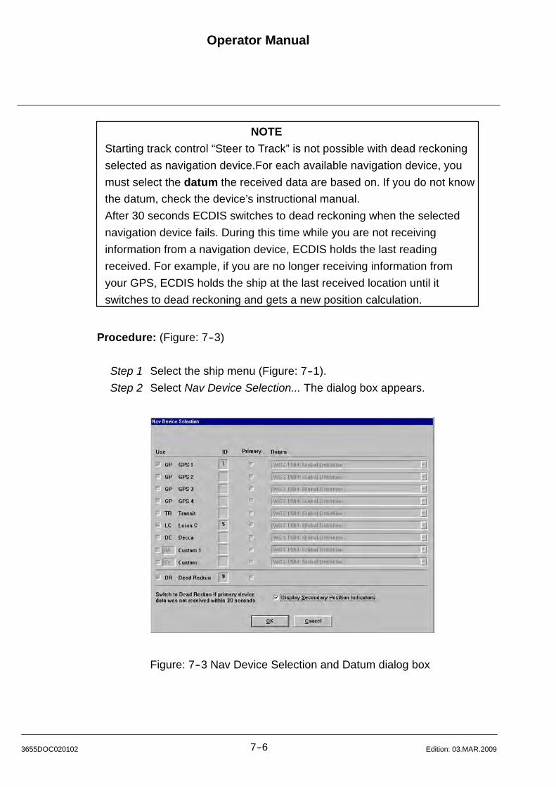
Operator Manual
7--63655DOC020102 Edition: 03.MAR.2009
NOTE
Starting track control “Steer to Track” is not possible with dead reckoning
selected as navigation device.For each available navigation device, you
must select the datum the received data are based on. If you do not know
the datum, check the device’s instructional manual.
After 30 seconds ECDIS switches to dead reckoning when the selected
navigation device fails. During this time while you are not receiving
information from a navigation device, ECDIS holds the last reading
received. For example, if you are no longer receiving information from
your GPS, ECDIS holds the ship at the last received location until it
switches to dead reckoning and gets a new position calculation.
Procedure: (Figure: 7--3)
Step 1 Select the ship menu (Figure: 7--1).
Step 2 Select Nav Device Selection... The dialog box appears.
Figure: 7--3 Nav Device Selection and Datum dialog box
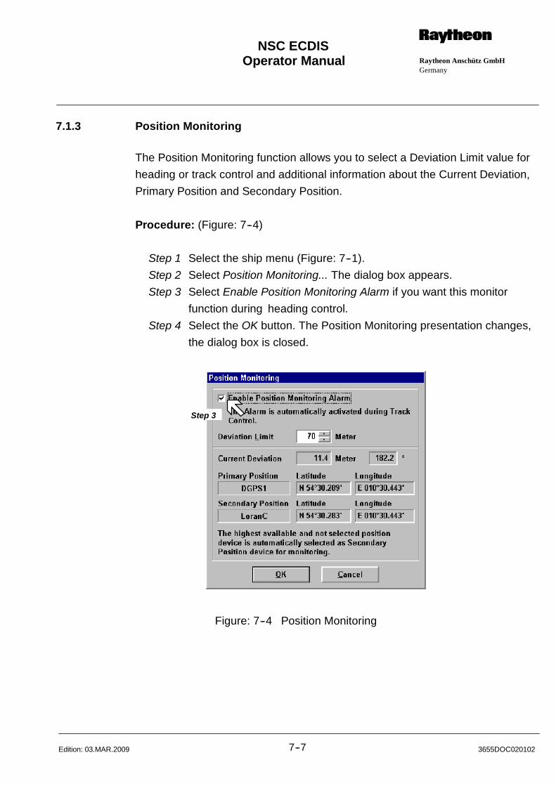
Operator Manual Raytheon Anschütz GmbHGermany
RNSC ECDIS
7--7 3655DOC020102Edition: 03.MAR.2009
7.1.3 Position Monitoring
The Position Monitoring function allows you to select a Deviation Limit value for
heading or track control and additional information about the Current Deviation,
Primary Position and Secondary Position.
Procedure: (Figure: 7--4)
Step 1 Select the ship menu (Figure: 7--1).
Step 2 Select Position Monitoring... The dialog box appears.
Step 3 Select Enable Position Monitoring Alarm if you want this monitor
function during heading control.
Step 4 Select the OK button. The Position Monitoring presentation changes,
the dialog box is closed.
Step 3
Figure: 7--4 Position Monitoring
Operator Manual
7--83655DOC020102 Edition: 03.MAR.2009
7.1.4 Dead Reckoning
The Dead Reckoning feature serves two purposes:
It is a means to calculate your position from the available speed and heading
values, if your navigation device(s) fails;
It allows you to demonstrate or practice using ECDIS by simulation ship‘s
motion.
In order to simulate ship‘s motion with dead reckoning, you must select Dead
Reckon as an available ”Navigation device” (chapter 7.1.2).
During Dead Reckon mode, you can select whether or not ECDIS will use the
heading from the GYRO and the bottom track speed from the speed log. If the
devices are available, you can select the ”Get from Nav Device” check boxes for
the course and/or the speed. If ECDIS receives a valid reading while these
check boxes are checked, it will adjust the vessel accordingly.
ECDIS switches automatically to Dead Reckon if the selected positioning device
fails, as long as the Gyro and Speed Log are active. When it switches, an alarm
sounds, autopilot track control is turned off (if it was on), and a mark appears on
the ship’s track with the time that dead reckoning stared. ECDIS will simulate
ship‘s motion using the bearing from the Gyro and the speed from the Doppler
Log. If another available navigation position device is selected, ECDIS will not
resume track control (Steer to Track) automatically.
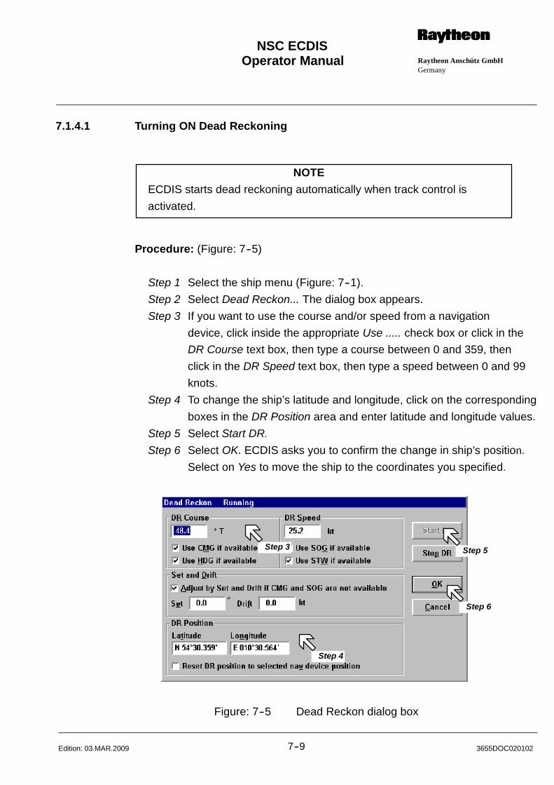
Operator Manual Raytheon Anschütz GmbHGermany
RNSC ECDIS
7--9 3655DOC020102Edition: 03.MAR.2009
7.1.4.1 Turning ON Dead Reckoning
NOTE
ECDIS starts dead reckoning automatically when track control is
activated.
Procedure: (Figure: 7--5)
Step 1 Select the ship menu (Figure: 7--1).
Step 2 Select Dead Reckon... The dialog box appears.
Step 3 If you want to use the course and/or speed from a navigation
device, click inside the appropriate Use ..... check box or click in the
DR Course text box, then type a course between 0 and 359, then
click in the DR Speed text box, then type a speed between 0 and 99
knots.
Step 4 To change the ship’s latitude and longitude, click on the corresponding
boxes in the DR Position area and enter latitude and longitude values.
Step 5 Select Start DR.
Step 6 Select OK. ECDIS asks you to confirm the change in ship’s position.
Select on Yes to move the ship to the coordinates you specified.
Step 3
Step 4
Step 5
Step 6
Figure: 7--5 Dead Reckon dialog box
Operator Manual
7--103655DOC020102 Edition: 03.MAR.2009
7.1.4.2 Turning OFF Dead Reckoning
NOTE
Turning OFF dead reckoning is not possible during track control or
while DR is selected as primary Nav Device .
Procedure:
Step 1 Select the ship menu (Figure: 7--1).
Step 2 Select Dead Reckon... The dialog box appears (Figure: 7--5).
Step 3 Select Stop DR then select OK.
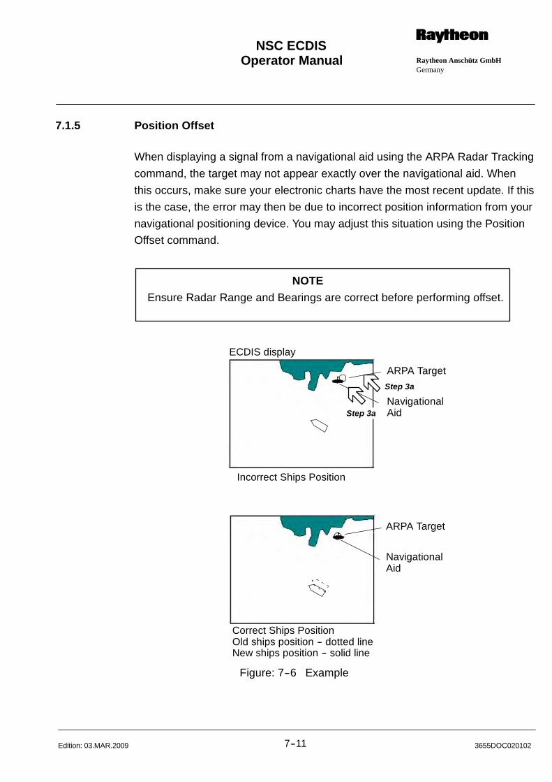
Operator Manual Raytheon Anschütz GmbHGermany
RNSC ECDIS
7--11 3655DOC020102Edition: 03.MAR.2009
7.1.5 Position Offset
When displaying a signal from a navigational aid using the ARPA Radar Tracking
command, the target may not appear exactly over the navigational aid. When
this occurs, make sure your electronic charts have the most recent update. If this
is the case, the error may then be due to incorrect position information from your
navigational positioning device. You may adjust this situation using the Position
Offset command.
NOTE
Ensure Radar Range and Bearings are correct before performing offset.
ARPA Target
NavigationalAid
ARPA Target
NavigationalAid
Incorrect Ships Position
Correct Ships PositionOld ships position -- dotted lineNew ships position -- solid line
ECDIS display
Step 3a
Step 3a
Figure: 7--6 Example

Operator Manual
7--123655DOC020102 Edition: 26.JUL.2010
7.1.5.1 Changing Ship’s Position
Procedure: (Figure: 7--6 and Figure: 7--7)
Step 1 Select the ship menu (Figure: 7--1).
Step 2 The cursor changes to target shape and the Ship Offset dialog box
appears. (Figure: 7--7).
Step 3 Enter the offset using the display
a) Click on ARPA target. The targets label appears in
the Selected area.
b) Click on the Navigational Aid over which the target should appear.
The navigational aid label appears on the Selected area.
Enter the offset using latitude and longitude
a) Click on OK.
The new offset (in meters) appears in the Latitude and Longitude
box, and the ship is repositioned on the screen.
Step 4 To cancel an offset
a) Select Position Offset from the Ship menu . The cursor
changes to target shape, and the Ship Offset dialog box appears.
b) Click on ”Zero” at the bottom of the dialog box.
The entries in the latitude and longitude box will return to zero, and
the boat is repositioned on the display.
c) Click on ”OK”.
Figure: 7--7 Position Offset
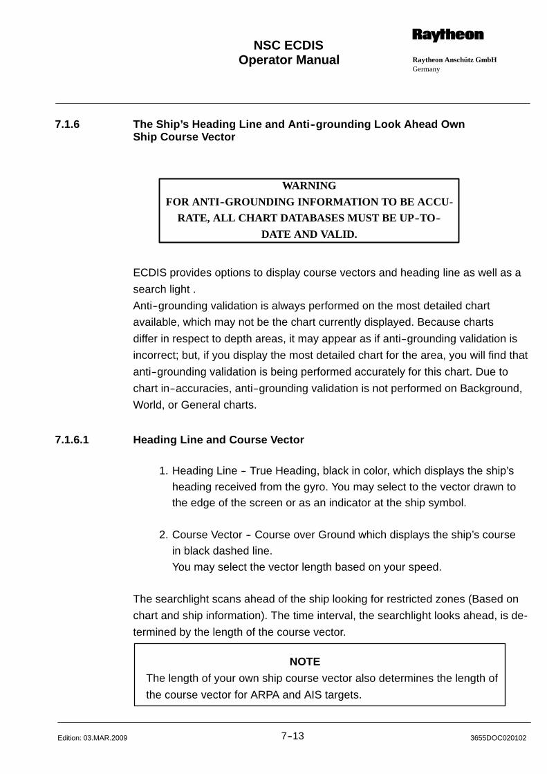
Operator Manual Raytheon Anschütz GmbHGermany
RNSC ECDIS
7--13 3655DOC020102Edition: 03.MAR.2009
7.1.6 The Ship’s Heading Line and Anti--grounding Look Ahead OwnShip Course Vector
WARNING
FOR ANTI--GROUNDING INFORMATION TO BE ACCU-
RATE, ALL CHART DATABASES MUST BE UP--TO--
DATE AND VALID.
ECDIS provides options to display course vectors and heading line as well as a
search light .
Anti--grounding validation is always performed on the most detailed chart
available, which may not be the chart currently displayed. Because charts
differ in respect to depth areas, it may appear as if anti--grounding validation is
incorrect; but, if you display the most detailed chart for the area, you will find that
anti--grounding validation is being performed accurately for this chart. Due to
chart in--accuracies, anti--grounding validation is not performed on Background,
World, or General charts.
7.1.6.1 Heading Line and Course Vector
1. Heading Line -- True Heading, black in color, which displays the ship’s
heading received from the gyro. You may select to the vector drawn tothe edge of the screen or as an indicator at the ship symbol.
2. Course Vector -- Course over Ground which displays the ship’s course
in black dashed line.
You may select the vector length based on your speed.
The searchlight scans ahead of the ship looking for restricted zones (Based on
chart and ship information). The time interval, the searchlight looks ahead, is de-
termined by the length of the course vector.
NOTE
The length of your own ship course vector also determines the length of
the course vector for ARPA and AIS targets.
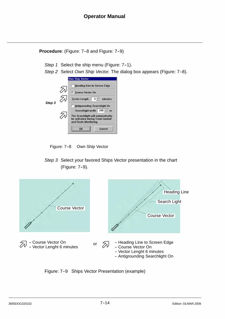
Operator Manual
7--143655DOC020102 Edition: 03.MAR.2009
Procedure: (Figure: 7--8 and Figure: 7--9)
Step 1 Select the ship menu (Figure: 7--1).
Step 2 Select Own Ship Vector. The dialog box appears (Figure: 7--8).
Step 3
Figure: 7--8 Own Ship Vector
Step 3 Select your favored Ships Vector presentation in the chart
(Figure: 7--9).
Search Light
Course Vector
Heading Line
-- Course Vector On-- Vector Lenght 6 minutes
-- Heading Line to Screen Edge-- Course Vector On-- Vector Lenght 6 minutes-- Antigrounding Searchlight On
or
Course Vector
Figure: 7--9 Ships Vector Presentation (example)
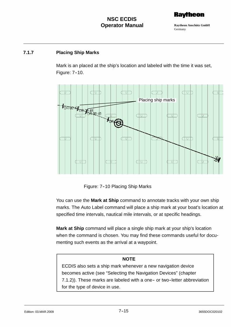
Operator Manual Raytheon Anschütz GmbHGermany
RNSC ECDIS
7--15 3655DOC020102Edition: 03.MAR.2009
7.1.7 Placing Ship Marks
Mark is an placed at the ship’s location and labeled with the time it was set,
Figure: 7--10.
Placing ship marks
Figure: 7--10 Placing Ship Marks
You can use the Mark at Ship command to annotate tracks with your own ship
marks. The Auto Label command will place a ship mark at your boat’s location at
specified time intervals, nautical mile intervals, or at specific headings.
Mark at Ship command will place a single ship mark at your ship’s location
when the command is chosen. You may find these commands useful for docu-
menting such events as the arrival at a waypoint.
NOTE
ECDIS also sets a ship mark whenever a new navigation device
becomes active (see “Selecting the Navigation Devices” (chapter
7.1.2)). These marks are labeled with a one-- or two--letter abbreviation
for the type of device in use.
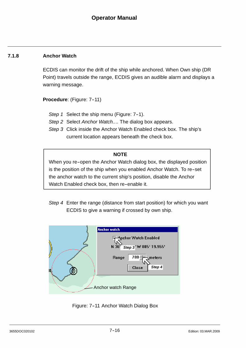
Operator Manual
7--163655DOC020102 Edition: 03.MAR.2009
7.1.8 Anchor Watch
ECDIS can monitor the drift of the ship while anchored. When Own ship (DR
Point) travels outside the range, ECDIS gives an audible alarm and displays a
warning message.
Procedure: (Figure: 7--11)
Step 1 Select the ship menu (Figure: 7--1).
Step 2 Select Anchor Watch.... The dialog box appears.
Step 3 Click inside the Anchor Watch Enabled check box. The ship’s
current location appears beneath the check box.
NOTE
When you re--open the Anchor Watch dialog box, the displayed position
is the position of the ship when you enabled Anchor Watch. To re--set
the anchor watch to the current ship’s position, disable the Anchor
Watch Enabled check box, then re--enable it.
Step 4 Enter the range (distance from start position) for which you want
ECDIS to give a warning if crossed by own ship.
Step 3
Step 4
Anchor watch Range
Figure: 7--11 Anchor Watch Dialog Box
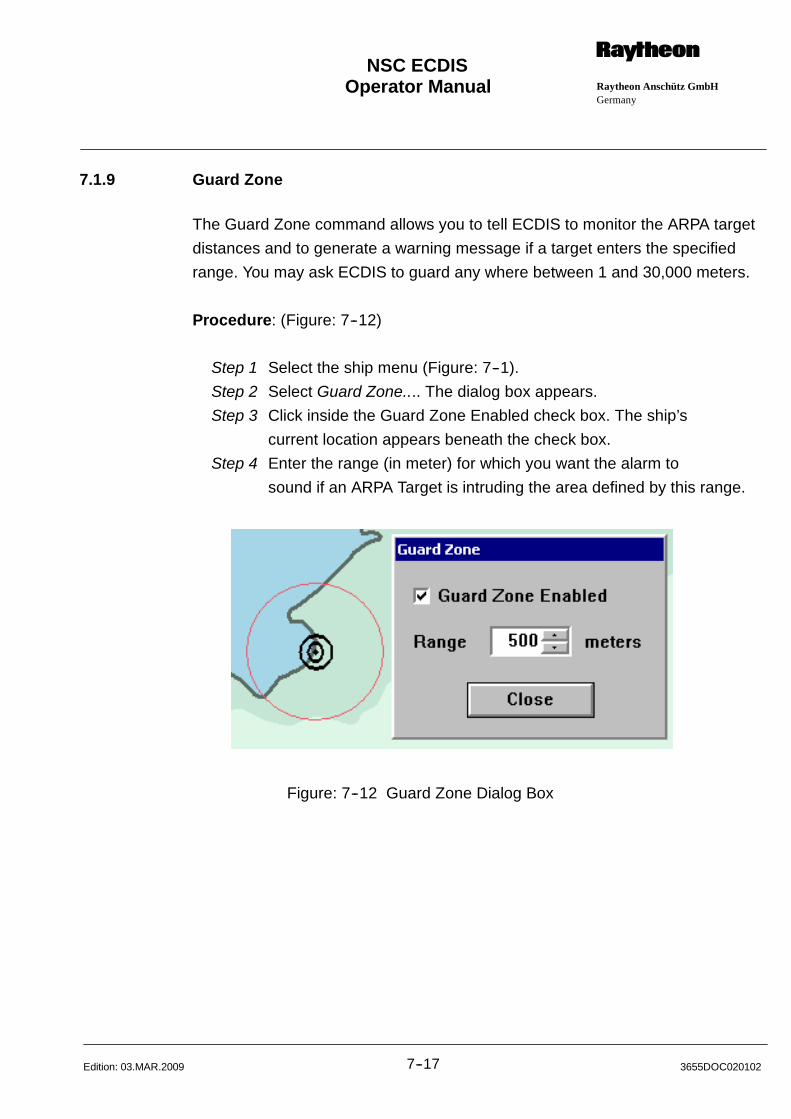
Operator Manual Raytheon Anschütz GmbHGermany
RNSC ECDIS
7--17 3655DOC020102Edition: 03.MAR.2009
7.1.9 Guard Zone
The Guard Zone command allows you to tell ECDIS to monitor the ARPA target
distances and to generate a warning message if a target enters the specified
range. You may ask ECDIS to guard any where between 1 and 30,000 meters.
Procedure: (Figure: 7--12)
Step 1 Select the ship menu (Figure: 7--1).
Step 2 Select Guard Zone.... The dialog box appears.
Step 3 Click inside the Guard Zone Enabled check box. The ship’s
current location appears beneath the check box.
Step 4 Enter the range (in meter) for which you want the alarm to
sound if an ARPA Target is intruding the area defined by this range.
Figure: 7--12 Guard Zone Dialog Box
Operator Manual
7--183655DOC020102 Edition: 26.JUL.2010
7.1.10 Man Overboard
When the Man Overboard command is selected, ECDIS posts an entry to the
Event Log. You may sound the alarm immediately by clicking on Alarm (a sec-
ond MOB entry and Alarm entry will be posted to the Event Log). If the Alarm is
signaled, ECDIS disconnects the autopilot, and places a ship mark on the
display.
The Man Overboard All Clear command turns off the general alarm and posts a
“man overboard cleared” entry in the Event Log.
Procedure: (Figure: 7--14)
Step 1 Select the ship menu (Figure: 7--1).
Step 2 Select the MOB button or select Man Overboard...command.
ECDIS places special MOB marker with time entry on the
chart, set an Alarm (acoustic and visual in the message display area).
Following MOB information displays in the status bar:
Position of the MOB, distance and bearing to the MOB
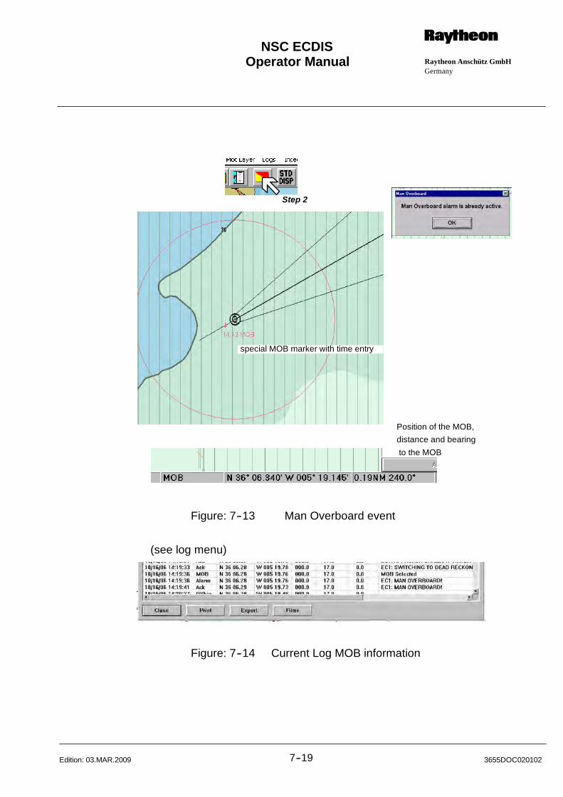
Operator Manual Raytheon Anschütz GmbHGermany
RNSC ECDIS
7--19 3655DOC020102Edition: 03.MAR.2009
Step 2
special MOB marker with time entry
Position of the MOB,
distance and bearing
to the MOB
Figure: 7--13 Man Overboard event
(see log menu)
Figure: 7--14 Current Log MOB information
Operator Manual
7--203655DOC020102 Edition: 03.MAR.2009
7.1.11 Clear or Cancel Man Overboard -- Alarm
Procedure:
Step 1 Select the ship menu (Figure: 7--1).
Step 2 Select Overboard All--Clear.
ECDIS turns off the alarm and posts an entry to the ship.

Operator Manual Raytheon Anschütz GmbHGermany
RNSC ECDIS
7--21 3655DOC020102Edition: 03.MAR.2009

Operator Manual Raytheon Anschütz GmbHGermany
RNSC ECDIS
8--1 3655DOC020102Edition: 03.MAR.2009
8 ROUTES MENU
8.1 ROUTE PLANNING
ECDIS has sophisticated route planning capabilities.
During route planning, each route section is automatic checked for free and safe
passage of the ship. The automatically check--up comprises Prohibited Areas,
Own Ship’s Contours, Buoys and Beacons known from and indicated in the sea
charts (CM93/3, S57).
In case a dangerous situation is realized during route planning, a corresponding
alarm is displayed in the Alarm Window (chapter 8.2.1.1).
ECDIS displays waypoints as circles. The active waypoint has an additional
circle around it. If you label your waypoints, the labels appear below the marker.
When a route is established, the following information is automatically displayed:
1. A planned track (course line) between the waypoints (is red in color and
appears as a thick dashed line between waypoints and a dashed linebetween the ship and the active waypoint).
Using the route planning feature, a primary as well as a secondary route
can be created. The route priority can be selected via menu function asneeded.
The primary route is displayed in thick, red, dashed lines.
The secondary route is displayed in thin, red, dashed lines.
2. The planned turning arc/radius (red in color); the turning arc which was
established when you entered the waypoint.
The turning arc/radius is limited to maximum 135.This limit value is checked during route planning and if this limit is ex--
ceeded an error message is released.
3. Crosstrack limit boundaries: width defined by the current cross--track
error alarm setting.
4. The wheelover point, or the point at which own ship must start turning to
follow the predicted turning arc.
Operator Manual
8--23655DOC020102 Edition: 03.MAR.2009
The wheel--over point position is controlled by the “Turning Response”
box in the Autopilot dialog box. Please see ”Driving an Autopilot”,chapter 12.1.6.
If you wish to have the current turning arc match the planned turning arc,you will need to change either your ship’s speed or the planned rate of
turn (see Autopilot dialog box, chapter 12.1.6).

Operator Manual Raytheon Anschütz GmbHGermany
RNSC ECDIS
8--3 3655DOC020102Edition: 03.MAR.2009
8.1.1 Route Description
oran
gegr
eyor
ange
grey
1
2
3
4
5
6
1
2
3
4
5
6
7
8
field
7
Figure: 8--1 Route Description
ECDIS does not select an active waypoint until the Steer to Track dialog box has
been opened and the active waypoint has been selected.
1 Waypoint
2 Ship, the position displays in field - 2- from the information panel
3 Ships vector True Heading, the arrowhead displays the ships position
after 6 min.
4 Planned speed
5 Limit for the XTD, value data see information panel - 6-
6 Active waypoint, value data see information panel - 7--
7 Scale bar > 1:80 000, part length in grey and orange color.
Scale bar < 1:80 000, part length in black and grey color.
Operator Manual
8--43655DOC020102 Edition: 03.MAR.2009
The following information is displayed:
1) Waypoints appear as a circle and an additional circle appearing around the
active waypoint.
2) Planned track (course line) between the waypoints (is red in color and
appears as a thick dashed line between waypoints and a thick dashed line
for the approach manoeuvre).
3) Planned turning arc/radius (red color); the turning arc which was
established as you entered the waypoint.
4) Fairlanes; defined by the current cross--track error alarm setting.
5) Ship’s bearing to the active waypoint.
Primary Routes indicates in dashed red thick line.
Secondary Routes indicates in dashed orange thin line.
6) Route planning. You can create two routes in the actual chart. The active
route is called Primary Route (indicates in dashed red thick line) and the
passive route is called Secondary Route.
If you wish to have the predicted turning arc match the planned turning arc, you
will need to change either your ship’s speed or the planned rate of turn (Autopilot
dialog box/ Integration menu).
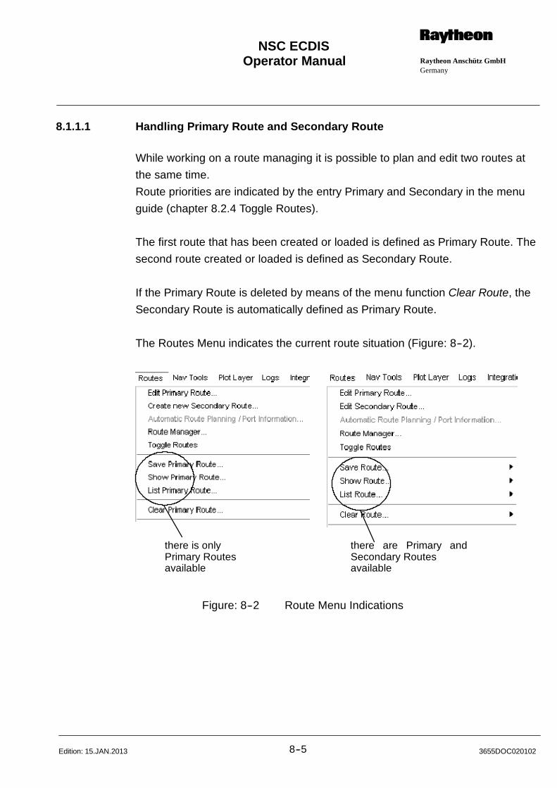
Operator Manual Raytheon Anschütz GmbHGermany
RNSC ECDIS
8--5 3655DOC020102Edition: 15.JAN.2013
8.1.1.1 Handling Primary Route and Secondary Route
While working on a route managing it is possible to plan and edit two routes at
the same time.
Route priorities are indicated by the entry Primary and Secondary in the menu
guide (chapter 8.2.4 Toggle Routes).
The first route that has been created or loaded is defined as Primary Route. The
second route created or loaded is defined as Secondary Route.
If the Primary Route is deleted by means of the menu function Clear Route, the
Secondary Route is automatically defined as Primary Route.
The Routes Menu indicates the current route situation (Figure: 8--2).
there is onlyPrimary Routesavailable
there are Primary andSecondary Routesavailable
Figure: 8--2 Route Menu Indications
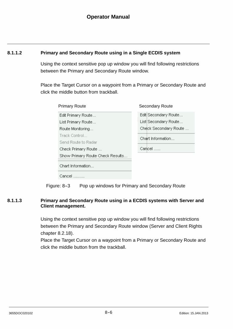
Operator Manual
8--63655DOC020102 Edition: 15.JAN.2013
8.1.1.2 Primary and Secondary Route using in a Single ECDIS system
Using the context sensitive pop up window you will find following restrictions
between the Primary and Secondary Route window.
Place the Target Cursor on a waypoint from a Primary or Secondary Route and
click the middle button from trackball.
Primary Route Secondary Route
Figure: 8--3 Pop up windows for Primary and Secondary Route
8.1.1.3 Primary and Secondary Route using in a ECDIS systems with Server andClient management.
Using the context sensitive pop up window you will find following restrictions
between the Primary and Secondary Route window (Server and Client Rights
chapter 8.2.18).
Place the Target Cursor on a waypoint from a Primary or Secondary Route and
click the middle button from the trackball.
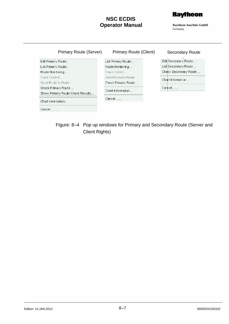
Operator Manual Raytheon Anschütz GmbHGermany
RNSC ECDIS
8--7 3655DOC020102Edition: 15.JAN.2013
Primary Route (Server) Secondary RoutePrimary Route (Client)
Figure: 8--4 Pop up windows for Primary and Secondary Route (Server and
Client Rights)
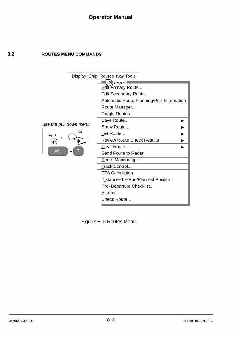
Operator Manual
8--83655DOC020102 Edition: 15.JAN.2013
8.2 ROUTES MENU COMMANDS
Edit Primary Route...
Edit Secondary Route...
Automatic Route Planning/Port Information
Route Manager...
Toggle Routes
Save Route... "
Show Route... "
List Route... "
Review Route Check Results "
Clear Route... "
Send Route to Radar
Route Monitoring...
Track Control...
ETA Calculation
Distance--To--Run/Planned Position
Pre--Departure Checklist...
Alarms...
Check Route...
Alt R+
use the pull down menu
Display
Step 1
Ship Routes Nav Tools
left
Figure: 8--5 Routes Menu
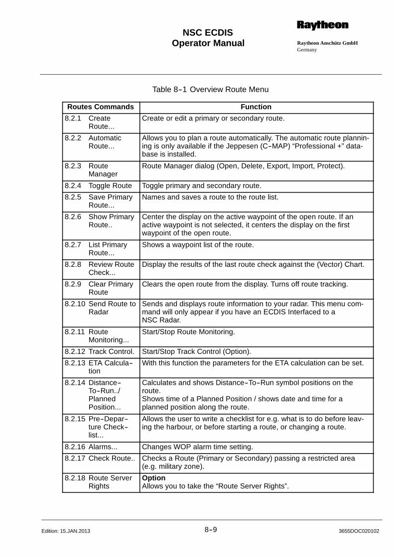
Operator Manual Raytheon Anschütz GmbHGermany
RNSC ECDIS
8--9 3655DOC020102Edition: 15.JAN.2013
Table 8--1 Overview Route Menu
Routes Commands Function
8.2.1 CreateRoute...
Create or edit a primary or secondary route.
8.2.2 AutomaticRoute...
Allows you to plan a route automatically. The automatic route plannin-ing is only available if the Jeppesen (C--MAP) “Professional +” data-base is installed.
8.2.3 RouteManager
Route Manager dialog (Open, Delete, Export, Import, Protect).
8.2.4 Toggle Route Toggle primary and secondary route.
8.2.5 Save PrimaryRoute...
Names and saves a route to the route list.
8.2.6 Show PrimaryRoute..
Center the display on the active waypoint of the open route. If anactive waypoint is not selected, it centers the display on the firstwaypoint of the open route.
8.2.7 List PrimaryRoute...
Shows a waypoint list of the route.
8.2.8 Review RouteCheck...
Display the results of the last route check against the (Vector) Chart.
8.2.9 Clear PrimaryRoute
Clears the open route from the display. Turns off route tracking.
8.2.10 Send Route toRadar
Sends and displays route information to your radar. This menu com-mand will only appear if you have an ECDIS Interfaced to aNSC Radar.
8.2.11 RouteMonitoring...
Start/Stop Route Monitoring.
8.2.12 Track Control. Start/Stop Track Control (Option).
8.2.13 ETA Calcula--tion
With this function the parameters for the ETA calculation can be set.
8.2.14 Distance--To--Run../PlannedPosition...
Calculates and shows Distance--To--Run symbol positions on theroute.Shows time of a Planned Position / shows date and time for aplanned position along the route.
8.2.15 Pre--Depar--ture Check--list...
Allows the user to write a checklist for e.g. what is to do before leav-ing the harbour, or before starting a route, or changing a route.
8.2.16 Alarms... Changes WOP alarm time setting.
8.2.17 Check Route.. Checks a Route (Primary or Secondary) passing a restricted area(e.g. military zone).
8.2.18 Route ServerRights
OptionAllows you to take the “Route Server Rights”.
Operator Manual
8--103655DOC020102 Edition: 15.JAN.2013
8.2.1 Edit Route Command
When you choose the Edit Route command, ECDIS displays the Edit Route
dialog box with the name of the open route (Primary or Secondary) in the title
bar.
Before creating a new primary or secondary route the last primary or secondary
route has to be cleared.
Procedure:
Step 1 Select the route menu (Figure: 8--5).
a) For creating a new route (chapter 8.2.1.1).
b) For performing actions in a current loaded primary or secondary
route (chapter 8.2.1.2).
Safety checks
While you are entering waypoints, ECDIS automatically checks the route and
fairlane (cross track limits) for unsafe and restricted areas as well as to see if
they are reasonable (relative to their geometrical coordinates).
The check results may be reviewed in a separate window (chapter 8.2.8).
If the geometrical limits are exceeded, you may either change the waypoint or
the waypoint radius.
NOTE
A route which contains dangers or which exceeds geometrical limits is
indicated by a red route name on the Information Panel.
A route which contains warning is indicated by an orange route name
on the Information Panel.
Operator Manual Raytheon Anschütz GmbHGermany
RNSC ECDIS
8--11 3655DOC020102Edition: 15.JAN.2013
8.2.1.1 Creating a Route
NOTE
The larger the scale of the display, the more accurately you can locate
specific coordinates. If you want to place a waypoint at a location that is
not in view, you can move the display using the Zoom feature, the Scale
and Center command, the View Area command, or the arrow keys
while the Edit Route dialog box is open.
Observe the Alarm Window (Information Panel), consider the messages
about:
Prohibited Areas, Own Ships Contours, Bouys and Beacons.
Before creating a new primary Route the last primary Route has to be cleared.
The same applies to the secondary route.
Select Clear Route from the Routes menu (chapter 8.2.9).
Select the desired chart area for the route planning.
Procedure: (Figure: 8--6)
Step 1 Select the route menu (Figure: 8--5).
Step 2 Select Clear Route.
(If the menu entry is colored in black otherwise follow Step 3)
Step 3 Select Create new Primary Route or select Create new Secondary
Route.
Step 4 Select the first waypoint position by cursor, press the [Left] button.
The waypoint number and the waypoint coordinates are shown in the
waypoint list.
Step 5 or-- Select numerical extend mode, enter Lat/Long, press the Extend
button. The waypoint number and the waypoint coordinates are
shown in the waypoint list.
Step 6 Select the next waypoint either by cursor or by numerical input (repeat
Step 4 or 5).
Step 7 Select the OK button, route planning is finished.
The route can now be saved under any name in a route list which is
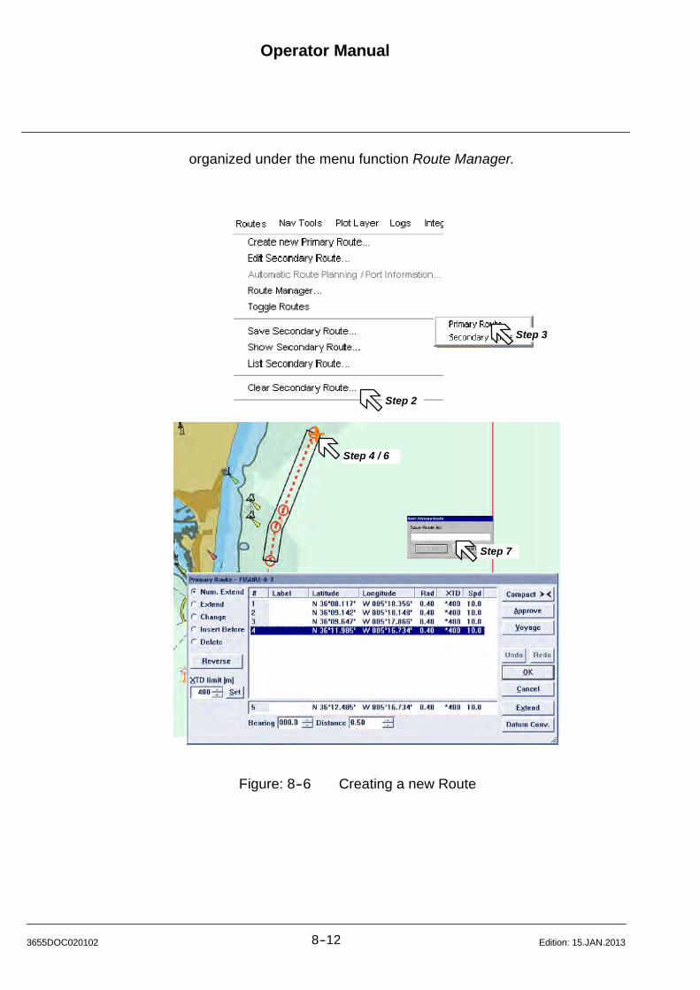
Operator Manual
8--123655DOC020102 Edition: 15.JAN.2013
organized under the menu function Route Manager.
Step 4 / 6
Step 2
Step 3
Step 7
Figure: 8--6 Creating a new Route
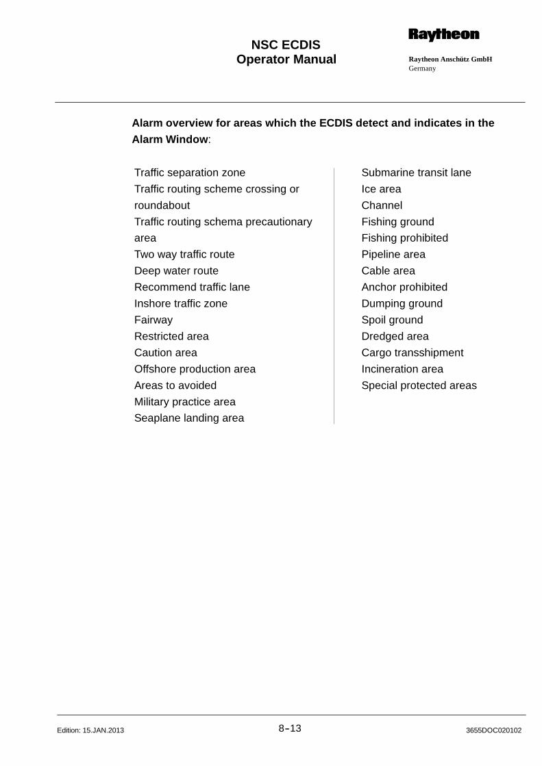
Operator Manual Raytheon Anschütz GmbHGermany
RNSC ECDIS
8--13 3655DOC020102Edition: 15.JAN.2013
Alarm overview for areas which the ECDIS detect and indicates in the
Alarm Window:
Traffic separation zone
Traffic routing scheme crossing or
roundabout
Traffic routing schema precautionary
area
Two way traffic route
Deep water route
Recommend traffic lane
Inshore traffic zone
Fairway
Restricted area
Caution area
Offshore production area
Areas to avoided
Military practice area
Seaplane landing area
Submarine transit lane
Ice area
Channel
Fishing ground
Fishing prohibited
Pipeline area
Cable area
Anchor prohibited
Dumping ground
Spoil ground
Dredged area
Cargo transshipment
Incineration area
Special protected areas
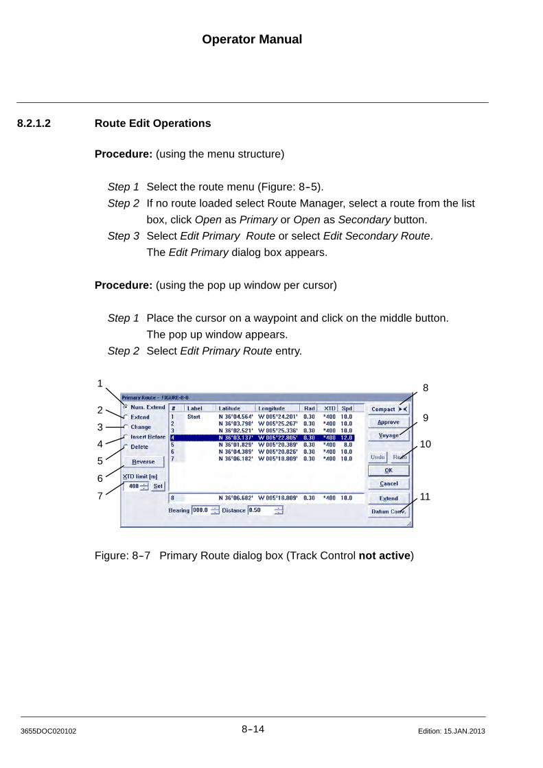
Operator Manual
8--143655DOC020102 Edition: 15.JAN.2013
8.2.1.2 Route Edit Operations
Procedure: (using the menu structure)
Step 1 Select the route menu (Figure: 8--5).
Step 2 If no route loaded select Route Manager, select a route from the list
box, click Open as Primary or Open as Secondary button.
Step 3 Select Edit Primary Route or select Edit Secondary Route.
The Edit Primary dialog box appears.
Procedure: (using the pop up window per cursor)
Step 1 Place the cursor on a waypoint and click on the middle button.
The pop up window appears.
Step 2 Select Edit Primary Route entry.
1
2
3
4
5
6
7
8
9
10
11
Figure: 8--7 Primary Route dialog box (Track Control not active)

Operator Manual Raytheon Anschütz GmbHGermany
RNSC ECDIS
8--15 3655DOC020102Edition: 15.JAN.2013
In place editing of waypoint properties is activated by double--clicking into a list
property field (see Figure: 8--8).
Figure: 8--8 Inplace editing
Setting the leg XTD field empty will activate the route XTD value for this leg.
(1) Option button Route: Num. Extend selected
Extending a route is as simple as entering new waypoints -- ECDIS
automatically adds them to the end of the route. Use the Edit Route command to
enter waypoints just as you do when creating the route; either select their
location in the display or specify their coordinates in the Latitude and Longitude
boxes within the new waypoint area.
Procedure: (e.g. using the pop up window per cursor)
Step 1.1 Place the cursor on a waypoint and click on middle button.
The pop up window appears.
Step 1.2 Select Edit Primary Route entry.
Step 1.3 Select the action point Num. Extend.
Step 1.4 Click on the Latitude and Longitude fields in the new waypoint area,
type in the hemisphere, degrees and minutes.
or Edit the Bearing and Distance fields to add a new relative position.
Step 1.5 Click on the Label field in the new waypoint area and enter a label.
Step 1.6 Click on the Radius field in the new waypoint area and enter the
desired value.
Step 1.7 Click on Extend. The waypoint appears in the waypoint list, and
a waypoint symbol appears in the display.
Operator Manual
8--163655DOC020102 Edition: 15.JAN.2013
To enter additional waypoints, repeat steps 4 -- 7. A waypoint
symbol appears at each location you specify and the route is
extended with fairlanes and a planned track (dashed).
Step 1.8 Click on Ok. The Save Route dialog box appears.
Step 1.9 To save the route, type a name of up to 25 characters in the text
box, then click on OK. If you do not want to save the route, click on
Cancel.
(2) Option button Route: Extend selected
Extending a route is as simple as entering new waypoints -- ECDIS
automatically adds them to the end of the route. Use the Edit Route command to
enter waypoints just as you do when creating the route; select their location in
the display.
Step 2.1 To extend the route, enter waypoints in the display per cursor.
Step 2.2 Select the OK button, if the a route extending is finished.
The Save Route dialogue box appears displaying the name of the
route.
Step 2.3 To save the route using the same name, click on OK. If you want to
save the route using a new name of up to 25 characters, then click
on OK. If you do not want to save your changes, click on Cancel.
(3) Option button Route: Change selected (Figure: 8--9)
You can change a waypoint’s location either by moving it in the display or by
using the Latitude and Longitude boxes to specify new coordinates.
Step 3.1 Using the target cursor
Position the cursor over the desired waypoint and click the [Left]
button or select the waypoint in the list box. Position the cursor at
the Waypoints new location and click the [Left] button. The
waypoint is repositioned in the display and the route is redrawn.
The Waypoints new coordinates are displayed in the Waypoint list
box.
or Using waypoint list in the dialog box
Operator Manual Raytheon Anschütz GmbHGermany
RNSC ECDIS
8--17 3655DOC020102Edition: 15.JAN.2013
Double click on the desired waypoint in the Latitude and Longitude
fields.
Click outside the editable fields ------ i.e. click on the number
column. The waypoint is repositioned in the display and the route is
redrawn.
NOTE
Datum is always WGS 1984.
Step 3.2 Select the OK button, if the a route changing is finished.
The Save Route dialogue box appears displaying the name of the
route.
Step 3.3 To save the route using the same name, click on OK. If you want to
save the route using a new name of up to 25 characters, then click
on OK. If you do not want to save your changes, click on Cancel.
In this case you can change a selected waypoint by changing the Radius or
the label (see Step 3.1).
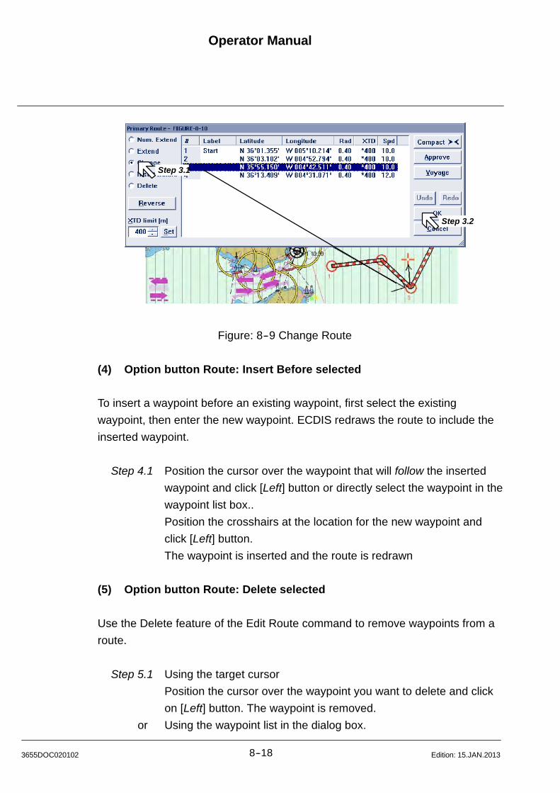
Operator Manual
8--183655DOC020102 Edition: 15.JAN.2013
Step 3.1
Step 3.2
Figure: 8--9 Change Route
(4) Option button Route: Insert Before selected
To insert a waypoint before an existing waypoint, first select the existing
waypoint, then enter the new waypoint. ECDIS redraws the route to include the
inserted waypoint.
Step 4.1 Position the cursor over the waypoint that will follow the inserted
waypoint and click [Left] button or directly select the waypoint in the
waypoint list box..
Position the crosshairs at the location for the new waypoint and
click [Left] button.
The waypoint is inserted and the route is redrawn
(5) Option button Route: Delete selected
Use the Delete feature of the Edit Route command to remove waypoints from a
route.
Step 5.1 Using the target cursor
Position the cursor over the waypoint you want to delete and click
on [Left] button. The waypoint is removed.
or Using the waypoint list in the dialog box.

Operator Manual Raytheon Anschütz GmbHGermany
RNSC ECDIS
8--19 3655DOC020102Edition: 15.JAN.2013
Click on the waypoint you want to delete, click on the middle
button, the pop up window appears, select Delete
Selected Waypoint. The waypoint is removed.
Step 5.2 Select the OK button, if the route changing is finished.
The Save Route dialogue box appears displaying the name of the
route.
Step 5.3 To save the route using the same name, click on OK. If you want to
save the route using a new name of up to 25 characters, then click
on OK. If you do not want to save your changes, click on Cancel.
(6) Option button Route: Reverse
If you are using the Track Control command and you begin to make changes to
a route (the Edit Route dialog box is opened), ECDIS automatically switches to
manual steering. Once you have made the changes, you must reactivate track
control (chapter 8.2.1.3). The Edit Route command offers a very helpful feature
that allows you to reverse the order of waypoints in a route. Use this feature
when you want to make a return trip following the same route.
Step 6.1 Click on Reverse. The order of the waypoints in the list box is
reversed.
Step 6.2 Select the OK button, if the route changing is finished.
The Save Route dialog box.
Step 6.3 To save the route using the same name, click on OK. If you want to
save the route using a new name of up to 25 characters, then click
on OK. If you do not want to save your changes, click on Cancel.
(7) XTD limit
Cross--Track error (Figure: 8--10)
Step 7.1 To enter a cross--track error, click in the XTD limit text box and
enter the cross--track in [m].
Click on Set to make the change.
The fairlanes on the display will be adjusted according to the
cross--track limit settings.
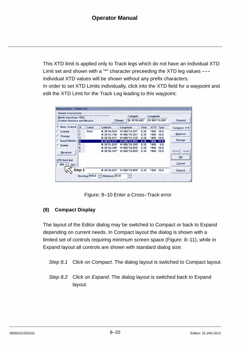
Operator Manual
8--203655DOC020102 Edition: 15.JAN.2013
This XTD limit is applied only to Track legs which do not have an individual XTD
Limit set and shown with a ”*” character preceeding the XTD leg values ------
individual XTD values will be shown without any prefix characters.
In order to set XTD Limits individually, click into the XTD field for a waypoint and
edit the XTD Limit for the Track Leg leading to this waypoint.
Step 1
Figure: 8--10 Enter a Cross--Track error
(8) Compact Display
The layout of the Editor dialog may be switched to Compact or back to Expand
depending on current needs. In Compact layout the dialog is shown with a
limited set of controls requiring minimum screen space (Figure: 8--11), while in
Expand layout all controls are shown with standard dialog size.
Step 8.1 Click on Compact. The dialog layout is switched to Compact layout.
Step 8.2 Click on Expand. The dialog layout is switched back to Expand
layout.
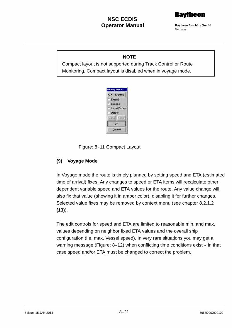
Operator Manual Raytheon Anschütz GmbHGermany
RNSC ECDIS
8--21 3655DOC020102Edition: 15.JAN.2013
NOTE
Compact layout is not supported during Track Control or Route
Monitoring. Compact layout is disabled when in voyage mode.
Figure: 8--11 Compact Layout
(9) Voyage Mode
In Voyage mode the route is timely planned by setting speed and ETA (estimated
time of arrival) fixes. Any changes to speed or ETA items will recalculate other
dependent variable speed and ETA values for the route. Any value change will
also fix that value (showing it in amber color), disabling it for further changes.
Selected value fixes may be removed by context menu (see chapter 8.2.1.2
(13)).
The edit controls for speed and ETA are limited to reasonable min. and max.
values depending on neighbor fixed ETA values and the overall ship
configuration (i.e. max. Vessel speed). In very rare situations you may get a
warning message (Figure: 8--12) when conflicting time conditions exist -- in that
case speed and/or ETA must be changed to correct the problem.
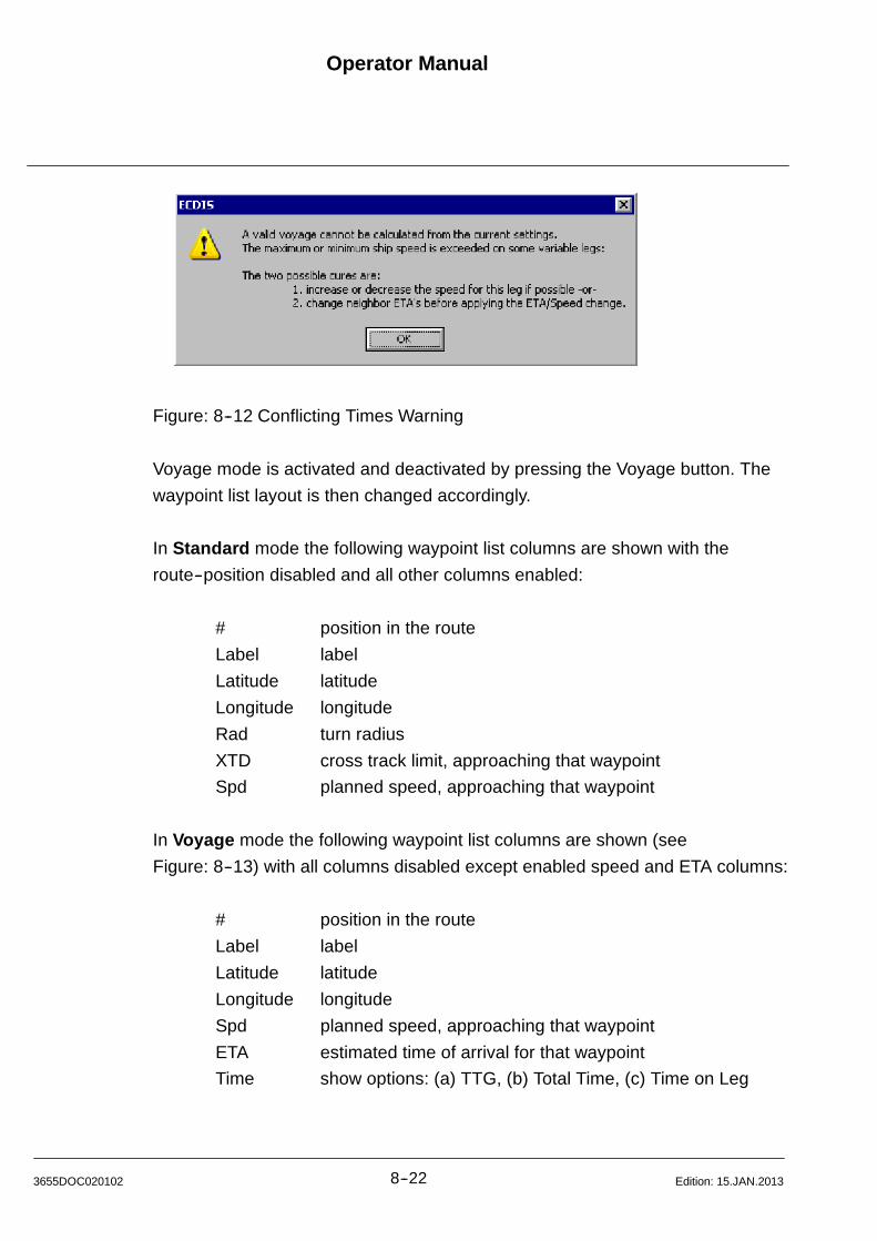
Operator Manual
8--223655DOC020102 Edition: 15.JAN.2013
Figure: 8--12 Conflicting Times Warning
Voyage mode is activated and deactivated by pressing the Voyage button. The
waypoint list layout is then changed accordingly.
In Standard mode the following waypoint list columns are shown with the
route--position disabled and all other columns enabled:
# position in the route
Label label
Latitude latitude
Longitude longitude
Rad turn radius
XTD cross track limit, approaching that waypoint
Spd planned speed, approaching that waypoint
In Voyage mode the following waypoint list columns are shown (see
Figure: 8--13) with all columns disabled except enabled speed and ETA columns:
# position in the route
Label label
Latitude latitude
Longitude longitude
Spd planned speed, approaching that waypoint
ETA estimated time of arrival for that waypoint
Time show options: (a) TTG, (b) Total Time, (c) Time on Leg
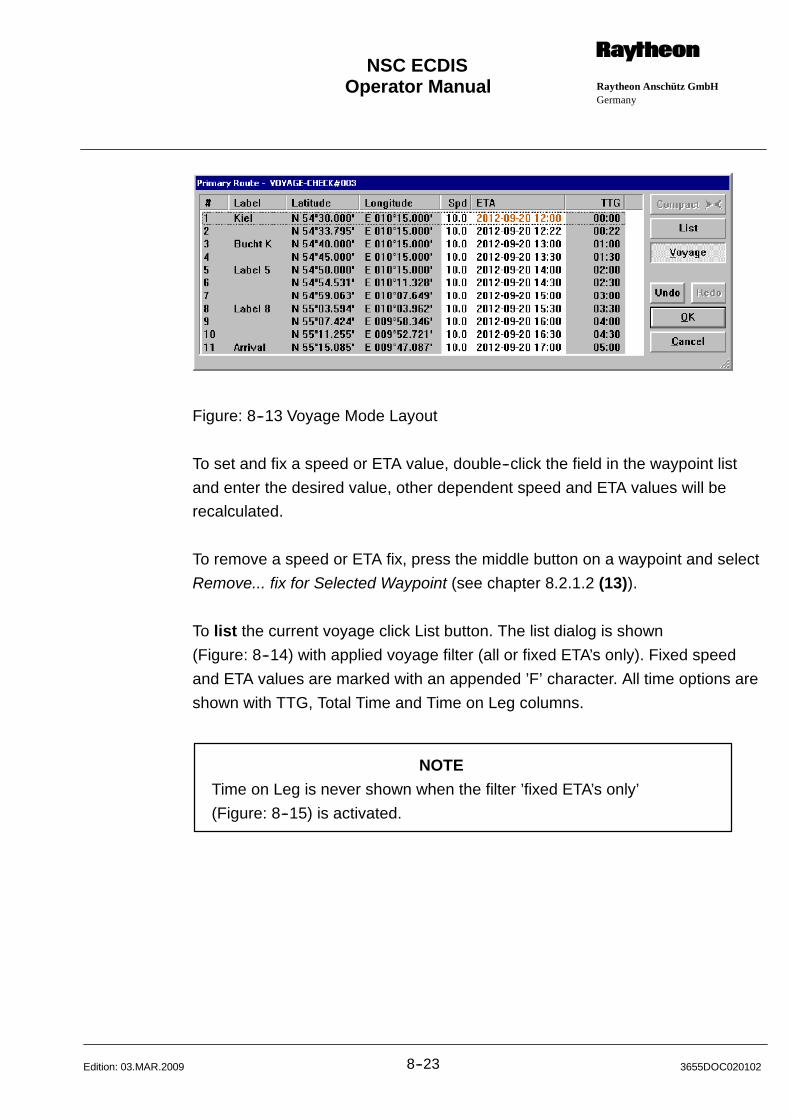
Operator Manual Raytheon Anschütz GmbHGermany
RNSC ECDIS
8--23 3655DOC020102Edition: 03.MAR.2009
Figure: 8--13 Voyage Mode Layout
To set and fix a speed or ETA value, double--click the field in the waypoint list
and enter the desired value, other dependent speed and ETA values will be
recalculated.
To remove a speed or ETA fix, press the middle button on a waypoint and select
Remove... fix for Selected Waypoint (see chapter 8.2.1.2 (13)).
To list the current voyage click List button. The list dialog is shown
(Figure: 8--14) with applied voyage filter (all or fixed ETA’s only). Fixed speed
and ETA values are marked with an appended ’F’ character. All time options are
shown with TTG, Total Time and Time on Leg columns.
NOTE
Time on Leg is never shown when the filter ’fixed ETA’s only’
(Figure: 8--15) is activated.
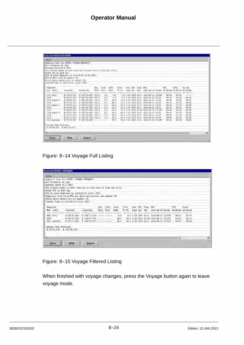
Operator Manual
8--243655DOC020102 Edition: 15.JAN.2013
Figure: 8--14 Voyage Full Listing
Figure: 8--15 Voyage Filtered Listing
When finished with voyage changes, press the Voyage button again to leave
voyage mode.
Operator Manual Raytheon Anschütz GmbHGermany
RNSC ECDIS
8--25 3655DOC020102Edition: 15.JAN.2013
(10) Undo / Redo
The Editor keeps track of all route changing operations. The Undo option will
revert to the last saved route state and the Redo option will re--do the last route
changing operation.
Up to 20 latest route changes are saved (see ECDIS configuration).
Step 10.1 Click on Undo. The last change operation is un--done.
Step 10.2 Click on Redo. The last change operation is re--done.
(11) Datum Conv
Option button Route: Num. Extend selected
Enter coordinates found on paper charts with different datum (not WGS 84).
When entering waypoints by specifying coordinates, the waypoints are always
converted to WGS 1984 coordinates. You may choose a different Datum when
entering coordinates.
NOTE
The datum conversion is only a display. It will not change the waypoint’s
coordinates. The stored waypoints remain unchanged in WSG 1984
coordinates.
Procedure: (e.g. using the pop up window per cursor)
Step 11.1 Place the cursor on a waypoint and click on middle button.
The pop up window appears.
Step 11.2 Select Edit Primary Route entry.
Step11. 3 Select the action point Num. Extend.

Operator Manual
8--263655DOC020102 Edition: 15.JAN.2013
Step 11.4 Click the Datum Conv. Button and select the corresponding datum
from the opening datum list, click Ok.
Step 11.5 Select existing waypoint in the waypoint list box.
Step 11.6 Enter waypoint coordinates in the Datum Latitude/Longitude fields,
and click on Convert. The coordinates will be converted and filled
automatically in the Lat/Lon of the selected waypoint.
Step 11.7 Click on Ok. The Save Route dialog box appears.
Step 11.8 To save the route, type a name of up to 25 characters in the text
box, then click on OK. If you do not want to save the route, click on
Cancel.
Figure: 8--16 Enter different Datum
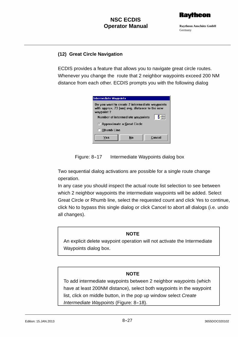
Operator Manual Raytheon Anschütz GmbHGermany
RNSC ECDIS
8--27 3655DOC020102Edition: 15.JAN.2013
(12) Great Circle Navigation
ECDIS provides a feature that allows you to navigate great circle routes.
Whenever you change the route that 2 neighbor waypoints exceed 200 NM
distance from each other. ECDIS prompts you with the following dialog
Figure: 8--17 Intermediate Waypoints dialog box
Two sequential dialog activations are possible for a single route change
operation.
In any case you should inspect the actual route list selection to see between
which 2 neighbor waypoints the intermediate waypoints will be added. Select
Great Circle or Rhumb line, select the requested count and click Yes to continue,
click No to bypass this single dialog or click Cancel to abort all dialogs (i.e. undo
all changes).
NOTE
An explicit delete waypoint operation will not activate the Intermediate
Waypoints dialog box.
NOTE
To add intermediate waypoints between 2 neighbor waypoints (which
have at least 200NM distance), select both waypoints in the waypoint
list, click on middle button, in the pop up window select Create
Intermediate Waypoints (Figure: 8--18).
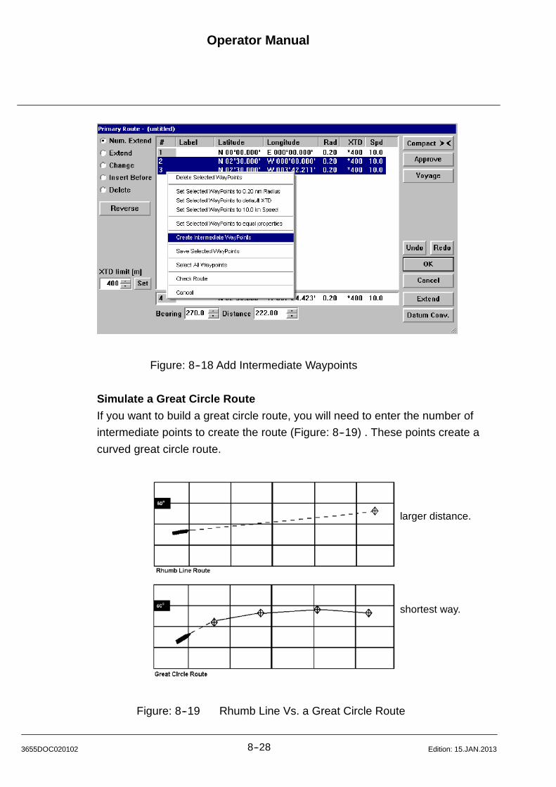
Operator Manual
8--283655DOC020102 Edition: 15.JAN.2013
Figure: 8--18 Add Intermediate Waypoints
Simulate a Great Circle Route
If you want to build a great circle route, you will need to enter the number of
intermediate points to create the route (Figure: 8--19) . These points create a
curved great circle route.
larger distance.
shortest way.
Figure: 8--19 Rhumb Line Vs. a Great Circle Route
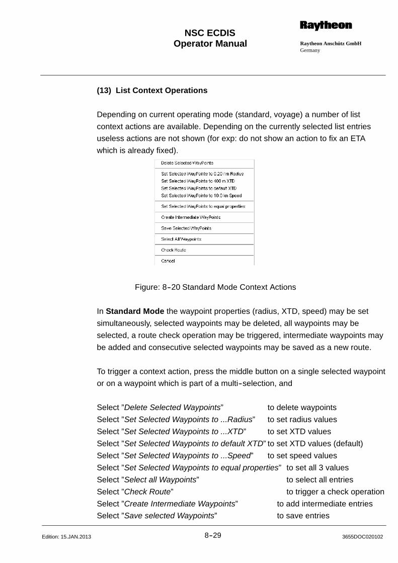
Operator Manual Raytheon Anschütz GmbHGermany
RNSC ECDIS
8--29 3655DOC020102Edition: 15.JAN.2013
(13) List Context Operations
Depending on current operating mode (standard, voyage) a number of list
context actions are available. Depending on the currently selected list entries
useless actions are not shown (for exp: do not show an action to fix an ETA
which is already fixed).
Figure: 8--20 Standard Mode Context Actions
In Standard Mode the waypoint properties (radius, XTD, speed) may be set
simultaneously, selected waypoints may be deleted, all waypoints may be
selected, a route check operation may be triggered, intermediate waypoints may
be added and consecutive selected waypoints may be saved as a new route.
To trigger a context action, press the middle button on a single selected waypoint
or on a waypoint which is part of a multi--selection, and
Select ”Delete Selected Waypoints” to delete waypoints
Select ”Set Selected Waypoints to ...Radius” to set radius values
Select ”Set Selected Waypoints to ...XTD” to set XTD values
Select ”Set Selected Waypoints to default XTD” to set XTD values (default)
Select ”Set Selected Waypoints to ...Speed” to set speed values
Select ”Set Selected Waypoints to equal properties” to set all 3 values
Select ”Select all Waypoints” to select all entries
Select ”Check Route” to trigger a check operation
Select ”Create Intermediate Waypoints” to add intermediate entries
Select ”Save selected Waypoints” to save entries
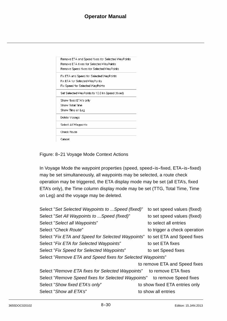
Operator Manual
8--303655DOC020102 Edition: 15.JAN.2013
Figure: 8--21 Voyage Mode Context Actions
In Voyage Mode the waypoint properties (speed, speed--is--fixed, ETA--is--fixed)
may be set simultaneously, all waypoints may be selected, a route check
operation may be triggered, the ETA display mode may be set (all ETA’s, fixed
ETA’s only), the Time column display mode may be set (TTG, Total Time, Time
on Leg) and the voyage may be deleted.
Select ”Set Selected Waypoints to ...Speed (fixed)” to set speed values (fixed)
Select ”Set All Waypoints to ...Speed (fixed)” to set speed values (fixed)
Select ”Select all Waypoints” to select all entries
Select ”Check Route” to trigger a check operation
Select ”Fix ETA and Speed for Selected Waypoints” to set ETA and Speed fixes
Select ”Fix ETA for Selected Waypoints” to set ETA fixes
Select ”Fix Speed for Selected Waypoints” to set Speed fixes
Select ”Remove ETA and Speed fixes for Selected Waypoints”
to remove ETA and Speed fixes
Select ”Remove ETA fixes for Selected Waypoints” to remove ETA fixes
Select ”Remove Speed fixes for Selected Waypoints” to remove Speed fixes
Select ”Show fixed ETA’s only” to show fixed ETA entries only
Select ”Show all ETA’s” to show all entries

Operator Manual Raytheon Anschütz GmbHGermany
RNSC ECDIS
8--31 3655DOC020102Edition: 15.JAN.2013
Select ”Show TTG” to show TTG values
Select ”Show Total Time” to show Total Time values
Select ”Show Time on Leg” to show Time on Leg values
Select ”Delete Voyage” to delete the voyage
8.2.1.3 If Track Control is active
If the route modifications are finished, the modified route has to be activated by
the Activate bottom. The text field at the bottom of the dialog box (Information)
displays corresponding messages.
Figure: 8--22 Change Primary Route (Track Control active)

Operator Manual
8--323655DOC020102 Edition: 15.JAN.2013
8.2.2 Automatic Route Planning and Port Information (Option)
The ECDIS offers a function for automatic route planning.
The Automatic route planning is only available if the Jeppesen (C--MAP)
database ”Professional+” is installed and has a valid license. This database
provides information about more than 5000 ports, certain passages and the
routing network.
NOTE
The available ports and passages as well as the created routes may
vary dependant on the version of the installed ”Professional+” database
The route will be created as e new secondary route. The route can be saved and
reloaded as any other manually created route.
8.2.2.1 Planning a Route
In this case the route start and destination location can be planned via a list or
via a cursor positioning in the chart.
Following combinations are possible:
-- with the Add port button (via a list) only or
-- by using the Add port button (via a list) and the Click Cursor button or
-- by using the Click Cursor button only
Click Cursor means one or both of these points can be entered via cursor in the
chart.
In this case the system will change the start and destination location to the
nearest suitable position.
This position information displays in the dialog box.
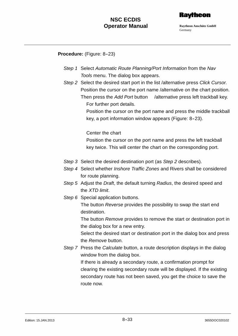
Operator Manual Raytheon Anschütz GmbHGermany
RNSC ECDIS
8--33 3655DOC020102Edition: 15.JAN.2013
Procedure: (Figure: 8--23)
Step 1 Select Automatic Route Planning/Port Information from the Nav
Tools menu. The dialog box appears.
Step 2 Select the desired start port in the list /alternative press Click Cursor.
Position the cursor on the port name /alternative on the chart position.
Then press the Add Port button /alternative press left trackball key.
For further port details.
Position the cursor on the port name and press the middle trackball
key, a port information window appears (Figure: 8--23).
Center the chart
Position the cursor on the port name and press the left trackball
key twice. This will center the chart on the corresponding port.
Step 3 Select the desired destination port (as Step 2 describes).
Step 4 Select whether Inshore Traffic Zones and Rivers shall be considered
for route planning.
Step 5 Adjust the Draft, the default turning Radius, the desired speed and
the XTD limit.
Step 6 Special application buttons.
The button Reverse provides the possibility to swap the start end
destination.
The button Remove provides to remove the start or destination port in
the dialog box for a new entry.
Select the desired start or destination port in the dialog box and press
the Remove button.
Step 7 Press the Calculate button, a route description displays in the dialog
window from the dialog box.
If there is already a secondary route, a confirmation prompt for
clearing the existing secondary route will be displayed. If the existing
secondary route has not been saved, you get the choice to save the
route now.
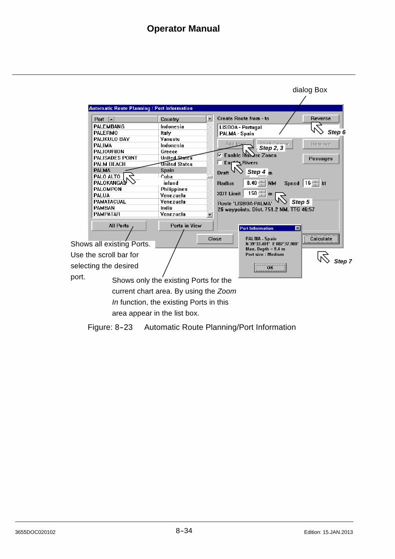
Operator Manual
8--343655DOC020102 Edition: 15.JAN.2013
Step 2, 3
Step 4
Step 5
Step 7
Step 6
dialog Box
Shows all existing Ports.
Use the scroll bar for
selecting the desired
port. Shows only the existing Ports for the
current chart area. By using the Zoom
In function, the existing Ports in this
area appear in the list box.
Figure: 8--23 Automatic Route Planning/Port Information

Operator Manual Raytheon Anschütz GmbHGermany
RNSC ECDIS
8--35 3655DOC020102Edition: 15.JAN.2013
8.2.2.2 Planning with certain Passages
Certain passages can be excluded from automatic route planning.
Procedure: (Figure: 8--23)
Step 1 Press the Passages button the show a list of all available passages.
By default all passages are enabled. Clear the according check marks
to disable passages and press the Apply button.
The new passage status will be used for the next route calculation.
Position the cursor on a passage and press the middle trackball
key twice.
This will center the chart on the corresponding port.
NOTE
It might happen, that some turns (e.g. in canals or port entries) need a
smaller turning radius than the given default turning radius, in this case
the turning radius will be reduced adequately on the relevant turns and
an information is provided in the status area of the window.
In some cases it might be possible that the route can be created but it
will not be possible to edit the route afterwards. The reason is, that in
some port entries and narrow passages the waypoints are located too
densely to allow modifications.
If the system can not create a route between two locations, this may
have one of the following causes:
-- Either a port or a part of the route is too shallow for the given draft.
-- The route would contain a too sharp turn for a valid route.
-- All possible passages are disabled.
Possible solutions:
-- Select a manually entered start or end position outside the port.
-- Verify the given draft.
-- Enable Inshore Zones and rivers if possible
-- Enable required passages.
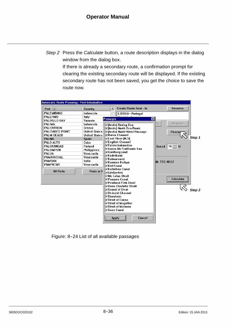
Operator Manual
8--363655DOC020102 Edition: 15.JAN.2013
Step 2 Press the Calculate button, a route description displays in the dialog
window from the dialog box.
If there is already a secondary route, a confirmation prompt for
clearing the existing secondary route will be displayed. If the existing
secondary route has not been saved, you get the choice to save the
route now.
Step 2
Step 1
Figure: 8--24 List of all available passages
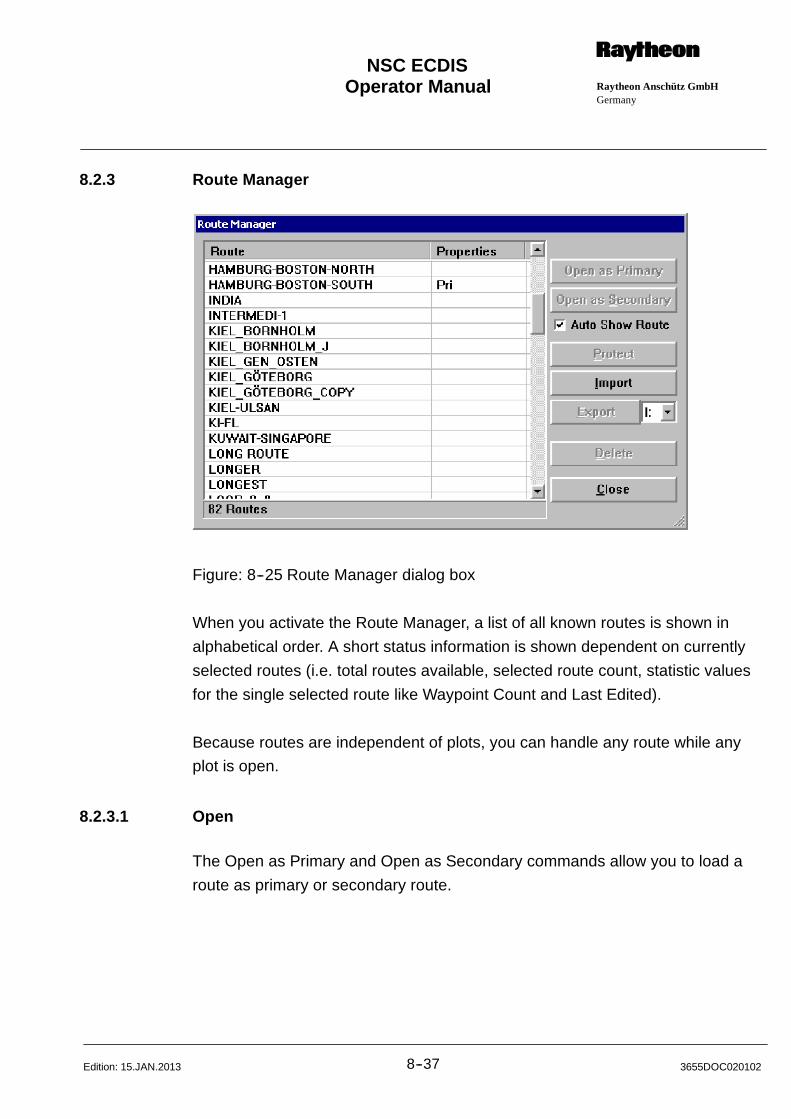
Operator Manual Raytheon Anschütz GmbHGermany
RNSC ECDIS
8--37 3655DOC020102Edition: 15.JAN.2013
8.2.3 Route Manager
Figure: 8--25 Route Manager dialog box
When you activate the Route Manager, a list of all known routes is shown in
alphabetical order. A short status information is shown dependent on currently
selected routes (i.e. total routes available, selected route count, statistic values
for the single selected route like Waypoint Count and Last Edited).
Because routes are independent of plots, you can handle any route while any
plot is open.
8.2.3.1 Open
The Open as Primary and Open as Secondary commands allow you to load a
route as primary or secondary route.

Operator Manual
8--383655DOC020102 Edition: 15.JAN.2013
NOTE
When you open a route, ECDIS draws fairlanes and a planned track
(dashed) between the waypoints. Use the Track Control command to
begin navigating to waypoint (see Activating Track Control (chapter8.2.12))
Procedure:
Step 1 Select Route Manager from the Routes menu.
Step 2 Click on the name of the route you want to open.
Step 3 Click on either Open as Primary or Open as Secondary button.
Option Enable Auto Show Route to automatically show a loaded route on
chart.
8.2.3.2 Delete
The Delete command allows you to delete routes from the route list that you no
longer need. Once a route is deleted, it cannot be retrieved.
Procedure:
Step 1 Select Route Manager from the Routes menu..
Step 2 Click on the name(s) of the route(s) you want to delete.
Click on Delete button. The route(s) is 8(are) deleted from the route
list and the list box.
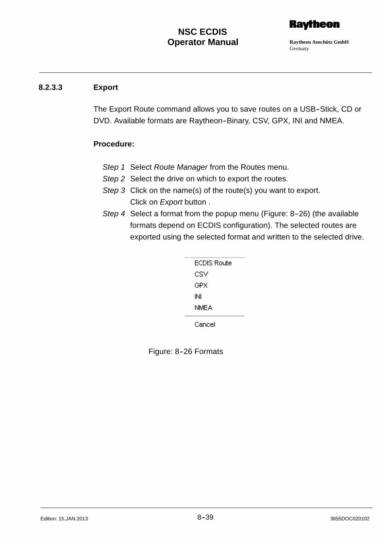
Operator Manual Raytheon Anschütz GmbHGermany
RNSC ECDIS
8--39 3655DOC020102Edition: 15.JAN.2013
8.2.3.3 Export
The Export Route command allows you to save routes on a USB--Stick, CD or
DVD. Available formats are Raytheon--Binary, CSV, GPX, INI and NMEA.
Procedure:
Step 1 Select Route Manager from the Routes menu.
Step 2 Select the drive on which to export the routes.
Step 3 Click on the name(s) of the route(s) you want to export.
Click on Export button .
Step 4 Select a format from the popup menu (Figure: 8--26) (the available
formats depend on ECDIS configuration). The selected routes are
exported using the selected format and written to the selected drive.
Figure: 8--26 Formats
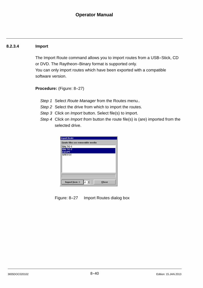
Operator Manual
8--403655DOC020102 Edition: 15.JAN.2013
8.2.3.4 Import
The Import Route command allows you to import routes from a USB--Stick, CD
or DVD. The Raytheon--Binary format is supported only.
You can only import routes which have been exported with a compatible
software version.
Procedure: (Figure: 8--27)
Step 1 Select Route Manager from the Routes menu..
Step 2 Select the drive from which to import the routes.
Step 3 Click on Import button. Select file(s) to import.
Step 4 Click on Import from button the route file(s) is (are) imported from the
selected drive.
Figure: 8--27 Import Routes dialog box
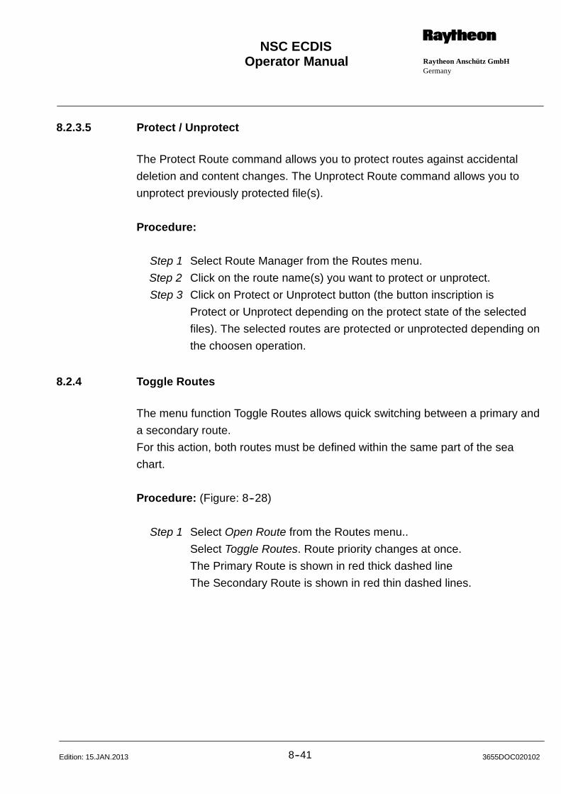
Operator Manual Raytheon Anschütz GmbHGermany
RNSC ECDIS
8--41 3655DOC020102Edition: 15.JAN.2013
8.2.3.5 Protect / Unprotect
The Protect Route command allows you to protect routes against accidental
deletion and content changes. The Unprotect Route command allows you to
unprotect previously protected file(s).
Procedure:
Step 1 Select Route Manager from the Routes menu.
Step 2 Click on the route name(s) you want to protect or unprotect.
Step 3 Click on Protect or Unprotect button (the button inscription is
Protect or Unprotect depending on the protect state of the selected
files). The selected routes are protected or unprotected depending on
the choosen operation.
8.2.4 Toggle Routes
The menu function Toggle Routes allows quick switching between a primary and
a secondary route.
For this action, both routes must be defined within the same part of the sea
chart.
Procedure: (Figure: 8--28)
Step 1 Select Open Route from the Routes menu..
Select Toggle Routes. Route priority changes at once.
The Primary Route is shown in red thick dashed line
The Secondary Route is shown in red thin dashed lines.
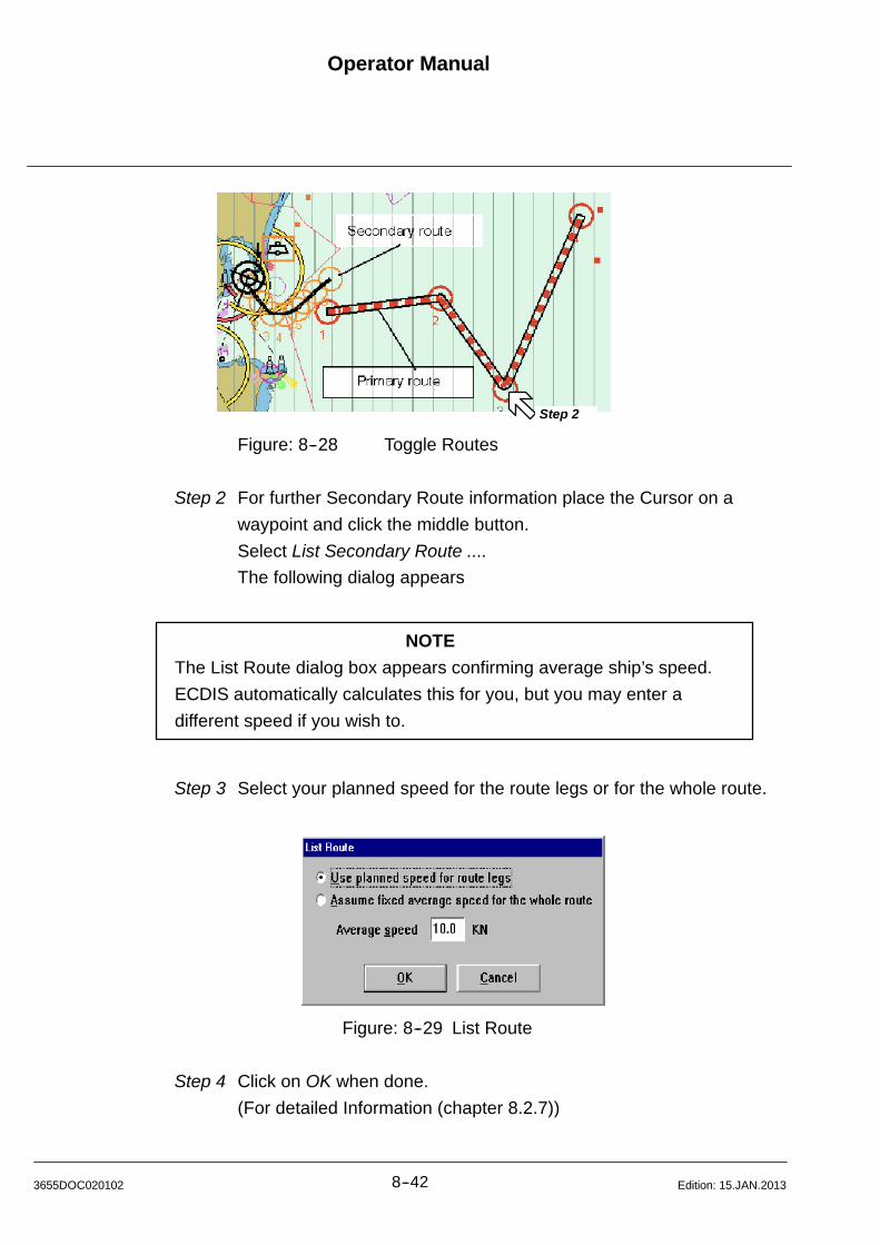
Operator Manual
8--423655DOC020102 Edition: 15.JAN.2013
Step 2
Figure: 8--28 Toggle Routes
Step 2 For further Secondary Route information place the Cursor on a
waypoint and click the middle button.
Select List Secondary Route ....
The following dialog appears
NOTE
The List Route dialog box appears confirming average ship’s speed.
ECDIS automatically calculates this for you, but you may enter a
different speed if you wish to.
Step 3 Select your planned speed for the route legs or for the whole route.
Figure: 8--29 List Route
Step 4 Click on OK when done.
(For detailed Information (chapter 8.2.7))
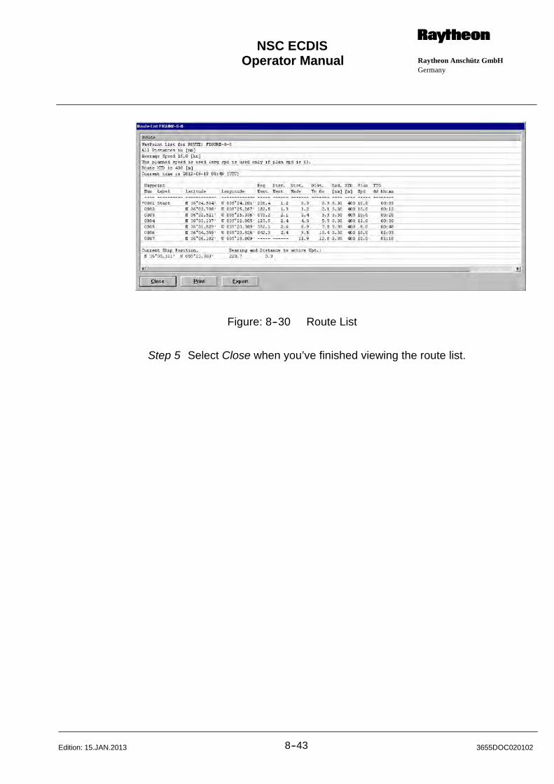
Operator Manual Raytheon Anschütz GmbHGermany
RNSC ECDIS
8--43 3655DOC020102Edition: 15.JAN.2013
Figure: 8--30 Route List
Step 5 Select Close when you’ve finished viewing the route list.
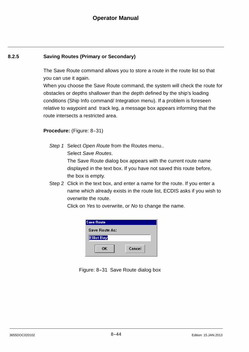
Operator Manual
8--443655DOC020102 Edition: 15.JAN.2013
8.2.5 Saving Routes (Primary or Secondary)
The Save Route command allows you to store a route in the route list so that
you can use it again.
When you choose the Save Route command, the system will check the route for
obstacles or depths shallower than the depth defined by the ship’s loading
conditions (Ship Info command/ Integration menu). If a problem is foreseen
relative to waypoint and track leg, a message box appears informing that the
route intersects a restricted area.
Procedure: (Figure: 8--31)
Step 1 Select Open Route from the Routes menu..
Select Save Routes.
The Save Route dialog box appears with the current route name
displayed in the text box. If you have not saved this route before,
the box is empty.
Step 2 Click in the text box, and enter a name for the route. If you enter a
name which already exists in the route list, ECDIS asks if you wish to
overwrite the route.
Click on Yes to overwrite, or No to change the name.
Figure: 8--31 Save Route dialog box
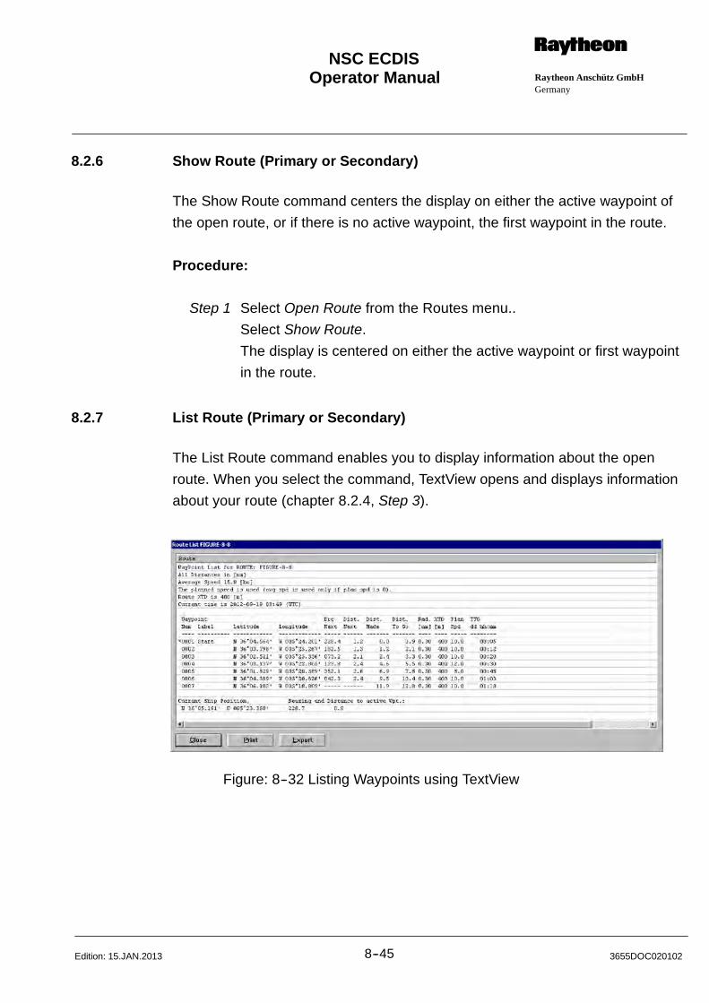
Operator Manual Raytheon Anschütz GmbHGermany
RNSC ECDIS
8--45 3655DOC020102Edition: 15.JAN.2013
8.2.6 Show Route (Primary or Secondary)
The Show Route command centers the display on either the active waypoint of
the open route, or if there is no active waypoint, the first waypoint in the route.
Procedure:
Step 1 Select Open Route from the Routes menu..
Select Show Route.
The display is centered on either the active waypoint or first waypoint
in the route.
8.2.7 List Route (Primary or Secondary)
The List Route command enables you to display information about the open
route. When you select the command, TextView opens and displays information
about your route (chapter 8.2.4, Step 3).
Figure: 8--32 Listing Waypoints using TextView
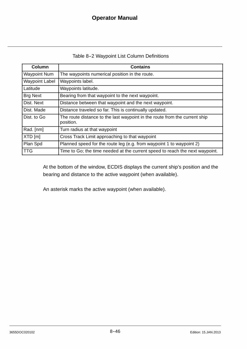
Operator Manual
8--463655DOC020102 Edition: 15.JAN.2013
Table 8--2 Waypoint List Column Definitions
Column Contains
Waypoint Num The waypoints numerical position in the route.
Waypoint Label Waypoints label.
Latitude Waypoints latitude.
Brg Next Bearing from that waypoint to the next waypoint.
Dist. Next Distance between that waypoint and the next waypoint.
Dist. Made Distance traveled so far. This is continually updated.
Dist. to Go The route distance to the last waypoint in the route from the current shipposition.
Rad. [nm] Turn radius at that waypoint
XTD [m] Cross Track Limit approaching to that waypoint
Plan Spd Planned speed for the route leg (e.g. from waypoint 1 to waypoint 2)
TTG Time to Go; the time needed at the current speed to reach the next waypoint.
At the bottom of the window, ECDIS displays the current ship’s position and the
bearing and distance to the active waypoint (when available).
An asterisk marks the active waypoint (when available).
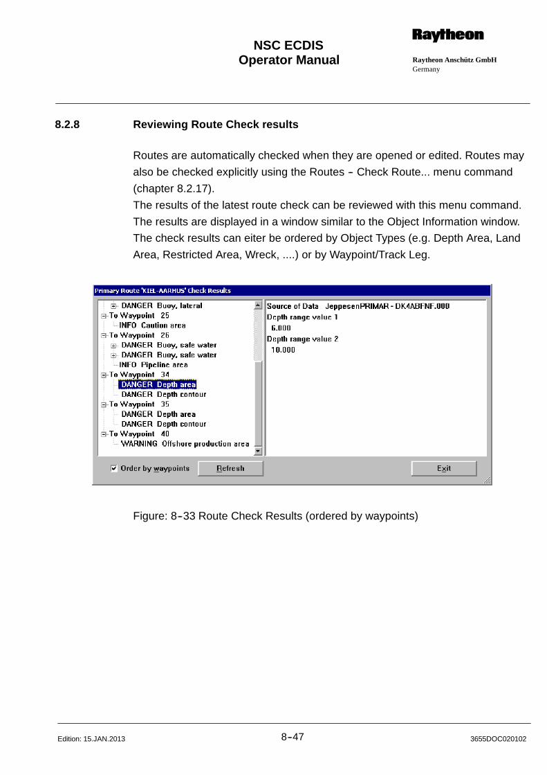
Operator Manual Raytheon Anschütz GmbHGermany
RNSC ECDIS
8--47 3655DOC020102Edition: 15.JAN.2013
8.2.8 Reviewing Route Check results
Routes are automatically checked when they are opened or edited. Routes may
also be checked explicitly using the Routes -- Check Route... menu command
(chapter 8.2.17).
The results of the latest route check can be reviewed with this menu command.
The results are displayed in a window similar to the Object Information window.
The check results can eiter be ordered by Object Types (e.g. Depth Area, Land
Area, Restricted Area, Wreck, ....) or by Waypoint/Track Leg.
Figure: 8--33 Route Check Results (ordered by waypoints)
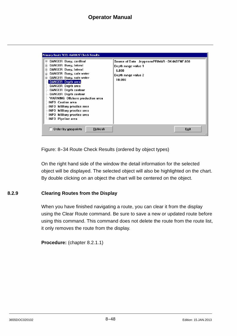
Operator Manual
8--483655DOC020102 Edition: 15.JAN.2013
Figure: 8--34 Route Check Results (ordered by object types)
On the right hand side of the window the detail information for the selected
object will be displayed. The selected object will also be highlighted on the chart.
By double clicking on an object the chart will be centered on the object.
8.2.9 Clearing Routes from the Display
When you have finished navigating a route, you can clear it from the display
using the Clear Route command. Be sure to save a new or updated route before
using this command. This command does not delete the route from the route list,
it only removes the route from the display.
Procedure: (chapter 8.2.1.1)

Operator Manual Raytheon Anschütz GmbHGermany
RNSC ECDIS
8--49 3655DOC020102Edition: 15.JAN.2013
8.2.10 Sending and Displaying ECDIS objects and Route on the Radar
ECDIS allows you to send and display objects on selected radars.
ECDIS is compatible with any device whose I/O ports are according to designed
NMEA 0183.
8.2.10.1 Send to Radar
Procedure: (Figure: 8--35)
Step 1 Click with the middle button on the object you want to send to your
radar (e.g. Depth contour);
then press Send to Radar from the dialog box which appears.
NOTE
The object information is sent to the radar. If the Send to Radar
command in not enabled, please check to make sure that the radar is
the active radar in the ARPA Radar Tracking dialog box (Radar
Tracking ON). Please see Integrating an ARPA Radar (chapter 12.1.4).
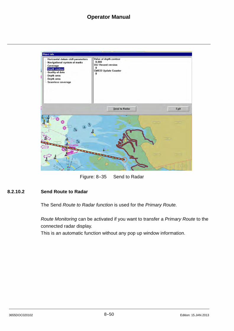
Operator Manual
8--503655DOC020102 Edition: 15.JAN.2013
Figure: 8--35 Send to Radar
8.2.10.2 Send Route to Radar
The Send Route to Radar function is used for the Primary Route.
Route Monitoring can be activated if you want to transfer a Primary Route to the
connected radar display.
This is an automatic function without any pop up window information.
Operator Manual Raytheon Anschütz GmbHGermany
RNSC ECDIS
8--51 3655DOC020102Edition: 15.JAN.2013
8.2.11 Route Monitoring
Route Monitoring can be activated if you want to follow a route in manual or
leading control, but also want to have the information provided in track control
mode, i.e. exceeding cross track limits, approaching a waypoint.
The ”Route Monitoring” function is used for a loaded route.
Any waypoint of the route can be selected by using the arrow buttons to switch
between waypoints or directly by clicking a waypoint by cursor.
Window “Select Active Waypoint” displays position coordinates of the selected
waypoint.
If you want to approach the first waypoint of a route a thin dashed line is drawn
from ship‘s symbol to the waypoint, provided with information for planned speed
and course to that waypoint (Figure: 8--36).
If the ship is on the track, the thin line is drawn from the current position of the
ship to the approached waypoint on the track.
The current track leg is also provided with information for planned speed and
course.

Operator Manual
8--523655DOC020102 Edition: 15.JAN.2013
Procedure: (Figure: 8--36)
Step 1 Select Open Route from the Routes menu..
Select Route Monitoring.
(Alterative selection, place the Target Cursor on a waypoint from a
Route and click the middle button.
Select Route Monitoring from the menu box which appears)
Step 2 Select the desired waypoint per left or right arrow button or per
target cursor.
speed
course to steer
course lineStep 2
Figure: 8--36 Route Monitoring
Operator Manual Raytheon Anschütz GmbHGermany
RNSC ECDIS
8--53 3655DOC020102Edition: 15.JAN.2013
8.2.12 Track Control
NOTE
Track Control is not an ECDIS function. To activate this function an
AUTOPILOT System has to be connected. For detailed information ask
Raytheon Marine.
If an Autopilot Remote Control Panel (ARCP Type 102--897, see
additional description no. 3307) is attached the operation is carried out
via this panel!
Once a route has been established, the Track Control command provides central
access to necessary navigation functions. You can use the Steer to Track dialog
box to:
Activate track control
Stop track control
Reactivate track control
The waypoint you are navigating to is called the ”active” waypoint.
ECDIS does not select an active waypoint until the Track Control command is
selected. Once the dialog box is open, it selects the first waypoint in the route as
the active waypoint.
Once an active waypoint has been selected, ECDIS circles the active waypoint
for which the waypoint alarm will be given, draws predicted and planned turning
arcs, as well as a dotted course line (planned track) between the waypoint and
your ship. Once you reach the active waypoint, ECDIS automatically makes the
next waypoint on the route the active waypoint and automatically draws the new
course line, and turning arcs. Even if you cut a corner off your route, or skip a
waypoint, ECDIS automatically makes the next waypoint the active one.
NOTE
If you want the Planned and Predicted Turning arc to be the same, you
must adjust either your rate of turn or the ship’s speed (Autopilot dialog
box/Integration (chapter 12.1.6)).
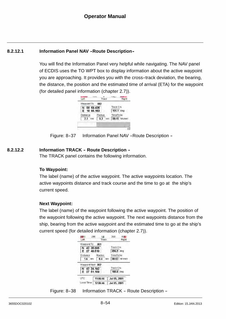
Operator Manual
8--543655DOC020102 Edition: 15.JAN.2013
8.2.12.1 Information Panel NAV --Route Description--
You will find the Information Panel very helpful while navigating. The NAV panel
of ECDIS uses the TO WPT box to display information about the active waypoint
you are approaching. It provides you with the cross--track deviation, the bearing,
the distance, the position and the estimated time of arrival (ETA) for the waypoint
(for detailed panel information (chapter 2.7)).
Figure: 8--37 Information Panel NAV --Route Description --
8.2.12.2 Information TRACK -- Route Description --The TRACK panel contains the following information.
To Waypoint:
The label (name) of the active waypoint. The active waypoints location. The
active waypoints distance and track course and the time to go at the ship’s
current speed.
Next Waypoint:
The label (name) of the waypoint following the active waypoint. The position of
the waypoint following the active waypoint. The next waypoints distance from the
ship, bearing from the active waypoint and the estimated time to go at the ship’s
current speed (for detailed information (chapter 2.7)).
Figure: 8--38 Information TRACK -- Route Description --
Operator Manual Raytheon Anschütz GmbHGermany
RNSC ECDIS
8--55 3655DOC020102Edition: 15.JAN.2013
8.2.12.3 Activating Track Control
NOTE
Track Control is not an ECDIS function. To activate this function an
AUTOPILOT System has to be connected.
For detailed information ask Raytheon Anschütz.
When you open the Steer to Track dialog box after creating or opening a route,
ECDIS automatically selects the first valid waypoint in the route as the active
waypoint. If you want to navigate to a different waypoint, you can do so by using
the arrow keys. When you select the new waypoint, ECDIS checks to make sure
it is a valid course line, then it circles the waypoint, redraws the course line, and
updates the Information Panel. If it is not a valid course line, then ECDIS grays
the dialog box, except the Select Active Waypoint arrow buttons, until a valid
waypoint is selected.
Selecting an active waypoint is very useful when you are navigating a long route.
For example, suppose you are navigating a route from Seattle to Pusan and
decide to stop in Prince Rupert. When you are ready to continue on to Pusan,
open your route again, and then using the Track Control command, you can
reassign the active waypoint and continue on the route.
Procedure: (Figure: 8--39)
Step 1 Select Track Control from the Routes menu.
(Alterative selection, place the Target Cursor on a waypoint and click
the middle button.
Select Track Control from the menu box which appears)
Step 2 Move the cursor over the waypoint to which you want to navigate and
click, or use the left and right arrow keys at the top left hand corner of
the dialog box.
Step 3 Select Text Point: Go to Waypoint.
Step 4 Click on OK. Track Control is activated
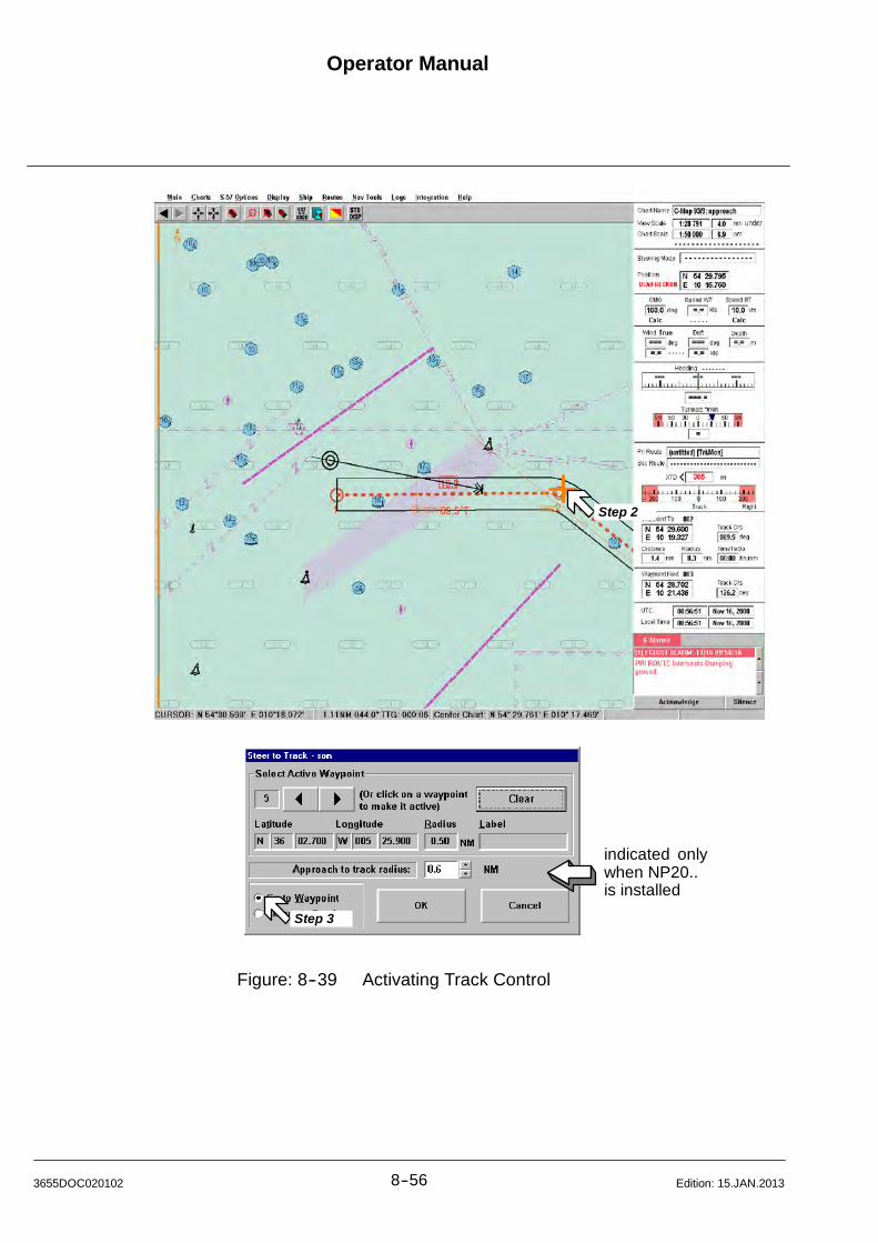
Operator Manual
8--563655DOC020102 Edition: 15.JAN.2013
Step 2
indicated onlywhen NP20..is installed
Step 3
Figure: 8--39 Activating Track Control
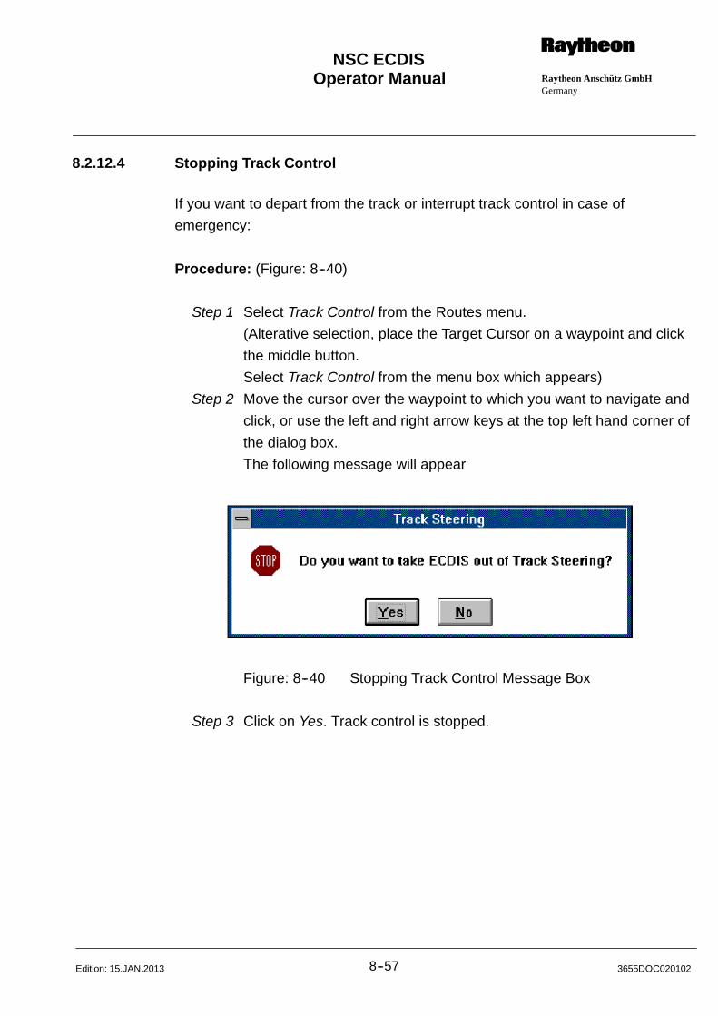
Operator Manual Raytheon Anschütz GmbHGermany
RNSC ECDIS
8--57 3655DOC020102Edition: 15.JAN.2013
8.2.12.4 Stopping Track Control
If you want to depart from the track or interrupt track control in case of
emergency:
Procedure: (Figure: 8--40)
Step 1 Select Track Control from the Routes menu.
(Alterative selection, place the Target Cursor on a waypoint and click
the middle button.
Select Track Control from the menu box which appears)
Step 2 Move the cursor over the waypoint to which you want to navigate and
click, or use the left and right arrow keys at the top left hand corner of
the dialog box.
The following message will appear
Figure: 8--40 Stopping Track Control Message Box
Step 3 Click on Yes. Track control is stopped.
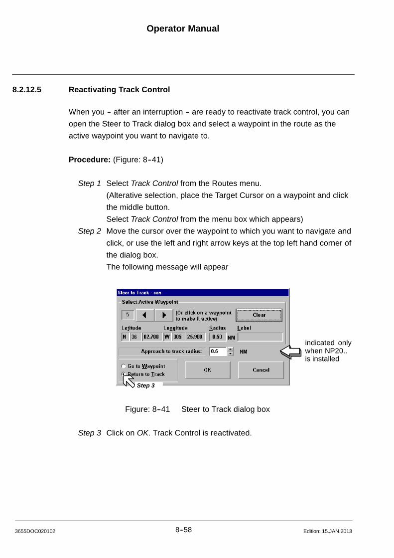
Operator Manual
8--583655DOC020102 Edition: 15.JAN.2013
8.2.12.5 Reactivating Track Control
When you -- after an interruption -- are ready to reactivate track control, you can
open the Steer to Track dialog box and select a waypoint in the route as the
active waypoint you want to navigate to.
Procedure: (Figure: 8--41)
Step 1 Select Track Control from the Routes menu.
(Alterative selection, place the Target Cursor on a waypoint and click
the middle button.
Select Track Control from the menu box which appears)
Step 2 Move the cursor over the waypoint to which you want to navigate and
click, or use the left and right arrow keys at the top left hand corner of
the dialog box.
The following message will appear
indicated onlywhen NP20..is installed
Step 3
Figure: 8--41 Steer to Track dialog box
Step 3 Click on OK. Track Control is reactivated.
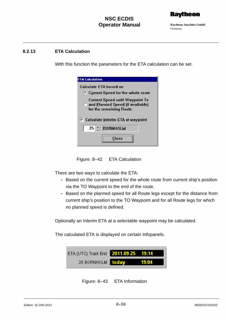
Operator Manual Raytheon Anschütz GmbHGermany
RNSC ECDIS
8--59 3655DOC020102Edition: 15.JAN.2013
8.2.13 ETA Calculation
With this function the parameters for the ETA calculation can be set.
Figure: 8--42 ETA Calculation
There are two ways to calculate the ETA:
-- Based on the current speed for the whole route from current ship’s position
via the TO Waypoint to the end of the route.
-- Based on the planned speed for all Route legs except for the distance from
current ship’s position to the TO Waypoint and for all Route legs for which
no planned speed is defined.
Optionally an Interim ETA at a selectable waypoint may be calculated.
The calculated ETA is displayed on certain Infopanels.
Figure: 8--43 ETA Information
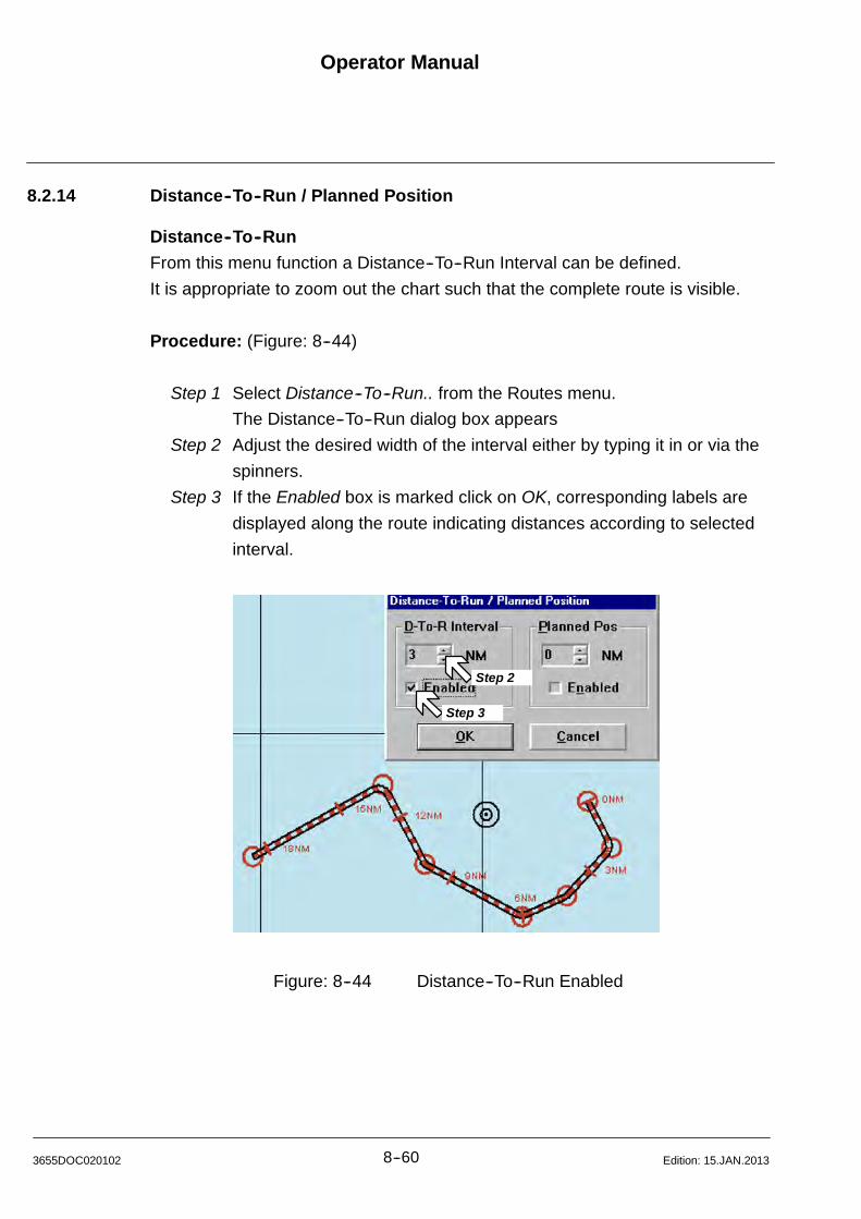
Operator Manual
8--603655DOC020102 Edition: 15.JAN.2013
8.2.14 Distance--To--Run / Planned Position
Distance--To--Run
From this menu function a Distance--To--Run Interval can be defined.
It is appropriate to zoom out the chart such that the complete route is visible.
Procedure: (Figure: 8--44)
Step 1 Select Distance--To--Run.. from the Routes menu.
The Distance--To--Run dialog box appears
Step 2 Adjust the desired width of the interval either by typing it in or via the
spinners.
Step 3 If the Enabled box is marked click on OK, corresponding labels are
displayed along the route indicating distances according to selected
interval.
Step 2
Step 3
Figure: 8--44 Distance--To--Run Enabled
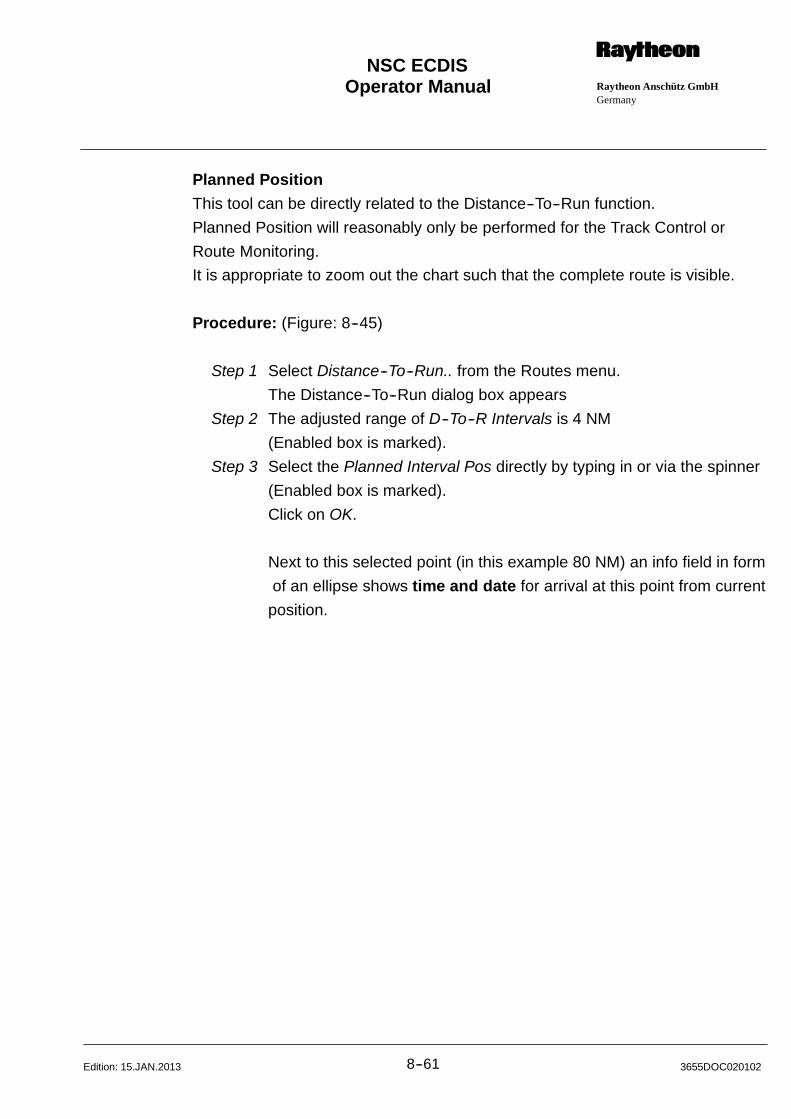
Operator Manual Raytheon Anschütz GmbHGermany
RNSC ECDIS
8--61 3655DOC020102Edition: 15.JAN.2013
Planned Position
This tool can be directly related to the Distance--To--Run function.
Planned Position will reasonably only be performed for the Track Control or
Route Monitoring.
It is appropriate to zoom out the chart such that the complete route is visible.
Procedure: (Figure: 8--45)
Step 1 Select Distance--To--Run.. from the Routes menu.
The Distance--To--Run dialog box appears
Step 2 The adjusted range of D--To--R Intervals is 4 NM
(Enabled box is marked).
Step 3 Select the Planned Interval Pos directly by typing in or via the spinner
(Enabled box is marked).
Click on OK.
Next to this selected point (in this example 80 NM) an info field in form
of an ellipse shows time and date for arrival at this point from current
position.
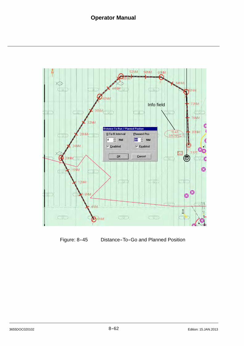
Operator Manual
8--623655DOC020102 Edition: 15.JAN.2013
Info field
Figure: 8--45 Distance--To--Go and Planned Position
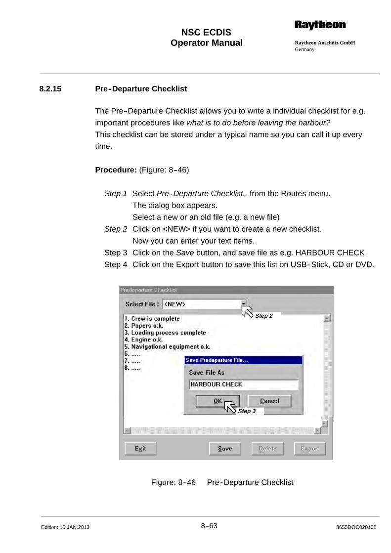
Operator Manual Raytheon Anschütz GmbHGermany
RNSC ECDIS
8--63 3655DOC020102Edition: 15.JAN.2013
8.2.15 Pre--Departure Checklist
The Pre--Departure Checklist allows you to write a individual checklist for e.g.
important procedures like what is to do before leaving the harbour?
This checklist can be stored under a typical name so you can call it up every
time.
Procedure: (Figure: 8--46)
Step 1 Select Pre--Departure Checklist.. from the Routes menu.
The dialog box appears.
Select a new or an old file (e.g. a new file)
Step 2 Click on <NEW> if you want to create a new checklist.
Now you can enter your text items.
Step 3 Click on the Save button, and save file as e.g. HARBOUR CHECK
Step 4 Click on the Export button to save this list on USB--Stick, CD or DVD.
Step 2
Step 3
Figure: 8--46 Pre--Departure Checklist
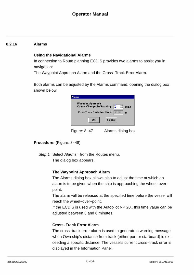
Operator Manual
8--643655DOC020102 Edition: 15.JAN.2013
8.2.16 Alarms
Using the Navigational Alarms
In connection to Route planning ECDIS provides two alarms to assist you in
navigation:
The Waypoint Approach Alarm and the Cross--Track Error Alarm.
Both alarms can be adjusted by the Alarms command, opening the dialog box
shown below.
Figure: 8--47 Alarms dialog box
Procedure: (Figure: 8--48)
Step 1 Select Alarms.. from the Routes menu.
The dialog box appears.
The Waypoint Approach Alarm
The Alarms dialog box allows also to adjust the time at which an
alarm is to be given when the ship is approaching the wheel--over--
point.
The alarm will be released at the specified time before the vessel will
reach the wheel--over--point.
If the ECDIS is used with the Autopilot NP 20.. this time value can be
adjusted between 3 and 6 minutes.
Cross--Track Error Alarm
The cross--track error alarm is used to generate a warning message
when Own ship’s distance from track (either port or starboard) is ex--
ceeding a specific distance. The vessel’s current cross--track error is
displayed in the Information Panel.
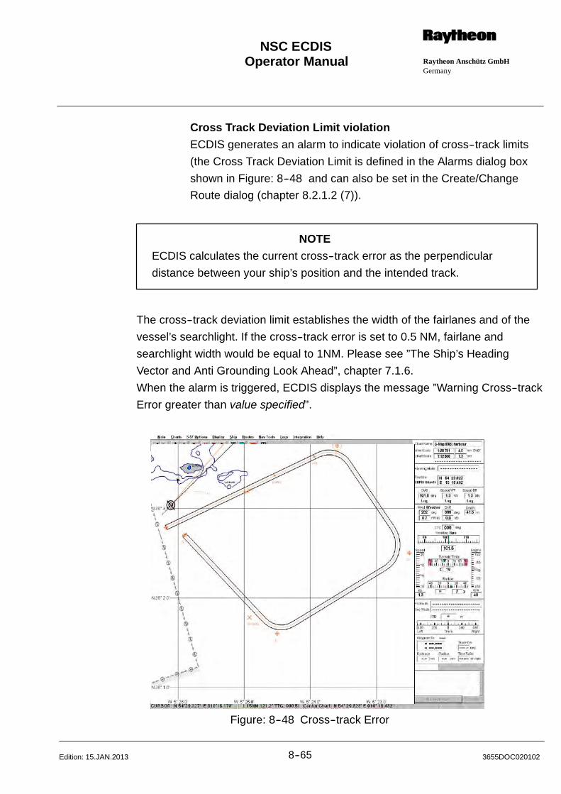
Operator Manual Raytheon Anschütz GmbHGermany
RNSC ECDIS
8--65 3655DOC020102Edition: 15.JAN.2013
Cross Track Deviation Limit violation
ECDIS generates an alarm to indicate violation of cross--track limits
(the Cross Track Deviation Limit is defined in the Alarms dialog box
shown in Figure: 8--48 and can also be set in the Create/Change
Route dialog (chapter 8.2.1.2 (7)).
NOTE
ECDIS calculates the current cross--track error as the perpendicular
distance between your ship’s position and the intended track.
The cross--track deviation limit establishes the width of the fairlanes and of the
vessel’s searchlight. If the cross--track error is set to 0.5 NM, fairlane and
searchlight width would be equal to 1NM. Please see ”The Ship’s Heading
Vector and Anti Grounding Look Ahead”, chapter 7.1.6.
When the alarm is triggered, ECDIS displays the message ”Warning Cross--track
Error greater than value specified”.
Figure: 8--48 Cross--track Error
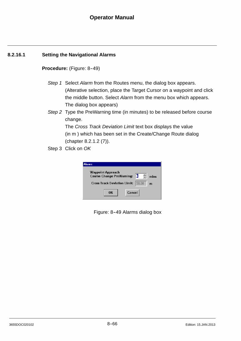
Operator Manual
8--663655DOC020102 Edition: 15.JAN.2013
8.2.16.1 Setting the Navigational Alarms
Procedure: (Figure: 8--49)
Step 1 Select Alarm from the Routes menu, the dialog box appears.
(Alterative selection, place the Target Cursor on a waypoint and click
the middle button. Select Alarm from the menu box which appears.
The dialog box appears)
Step 2 Type the PreWarning time (in minutes) to be released before course
change.
The Cross Track Deviation Limit text box displays the value
(in m ) which has been set in the Create/Change Route dialog
(chapter 8.2.1.2 (7)).
Step 3 Click on OK
Figure: 8--49 Alarms dialog box

Operator Manual Raytheon Anschütz GmbHGermany
RNSC ECDIS
8--67 3655DOC020102Edition: 15.JAN.2013
8.2.17 Check Route
Check Route considers the validity of objects limited in time in the sea chart
formats CM93/3 and S57.
Objects limited in time are:
S Prohibited Areas
S Own Ships Contours
S Buoys and Beacons.
Check Route is recommended for a check--over of a known route, for example,
that has to be sailed on a certain date.
It is possible that known routes were planned with an older chart version. With a
Chart Update, new situations can arise. Check Route examines the entire route
to that and effect and release alarm messages, if necessary. The individual route
sections are to be checked over (chapter 8.2.1.2).
Procedure: (Figure: 8--50)
Step 1 Select Open Route of the Routes menu, the dialog box appears.
Select on the name route name of interest.
Step 2 Click on either Open or Open and Show.
(Alterative double cklick on the route name will also open and
display the route)
Step 3 Select Check Route of the Routes menu, the dialog box appears.
Select a Date and click on Check Now.
The results will be displayed in the alarm window.
(only when a Primary Route selected) (only when a Primary Route and Secondary Route selected)
Figure: 8--50 Check Route
Operator Manual
8--683655DOC020102 Edition: 15.JAN.2013
8.2.18 ECDIS used as Route Server or Route Client (Option)
This functionality is only possible in connection with a navigation system
containing at least two ECDIS units.
Depending on the system configuration, one ECDIS can be the Route Server or
the Route Client.
Route Server Rights means:
The creation, handling and deleting of Primary and Secondary Routes.
The Primary Route is transferred to the Client ECDIS units and indicated
there.
Track Control can only be activated via the ECDIS having the Route Server
Rights.
Route Client Rights means:
The creation, handling and deleting of Secondary routes.
The Primary Route can be indicated, but not deleted.
Select Route Server means:
Procedure: (Figure: 8--51)
Step 1 Select Route Server Rights.. of the Routes menu.
Within a navigation system, only one ECDIS at a time can adopt the
status Route Server Rights.
The Routes menu changes.

Operator Manual Raytheon Anschütz GmbHGermany
RNSC ECDIS
8--69 3655DOC020102Edition: 15.JAN.2013
By selecting this route functionthe Client Status changes tothe Server Status.
Client Route Menu Server Route Menu
Step 1
Edit Primary Route...
Edit Secondary Route...
Automatic Route Planning/Port Information
Route Manager...
Toggle Routes
Save Route... "
Show Route... "
List Route... "
Review Route Check Results "
Clear Route... "
Send Route to Radar
Route Monitoring...
Track Control...
ETA Calculation
Distance--To--Run/Planned Position
Pre--Departure Checklist...
Alarms...
Check Route...
Route Server Rights
Figure: 8--51 Changing Route Rights Client to Server

Operator Manual
8--703655DOC020102 Edition: 15.JAN.2013
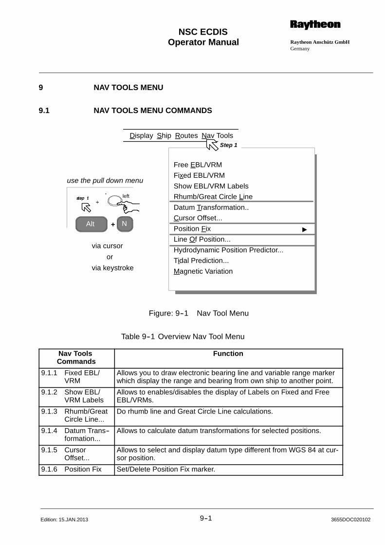
Operator Manual Raytheon Anschütz GmbHGermany
RNSC ECDIS
9--1 3655DOC020102Edition: 15.JAN.2013
9 NAV TOOLS MENU
9.1 NAV TOOLS MENU COMMANDS
Free EBL/VRM
Fixed EBL/VRM
Show EBL/VRM Labels
Rhumb/Great Circle Line
Datum Transformation..
Cursor Offset...
Position Fix "
Line Of Position...
Hydrodynamic Position Predictor...
Tidal Prediction...
Magnetic Variation
Alt N
via cursor
via keystroke
or
+
use the pull down menu
DisplayStep 1
Ship Routes Nav Tools
left
Figure: 9--1 Nav Tool Menu
Table 9--1 Overview Nav Tool Menu
Nav ToolsCommands
Function
9.1.1 Fixed EBL/VRM
Allows you to draw electronic bearing line and variable range markerwhich display the range and bearing from own ship to another point.
9.1.2 Show EBL/VRM Labels
Allows to enables/disables the display of Labels on Fixed and FreeEBL/VRMs.
9.1.3 Rhumb/GreatCircle Line...
Do rhumb line and Great Circle Line calculations.
9.1.4 Datum Trans--formation...
Allows to calculate datum transformations for selected positions.
9.1.5 CursorOffset...
Allows to select and display datum type different from WGS 84 at cur-sor position.
9.1.6 Position Fix Set/Delete Position Fix marker.
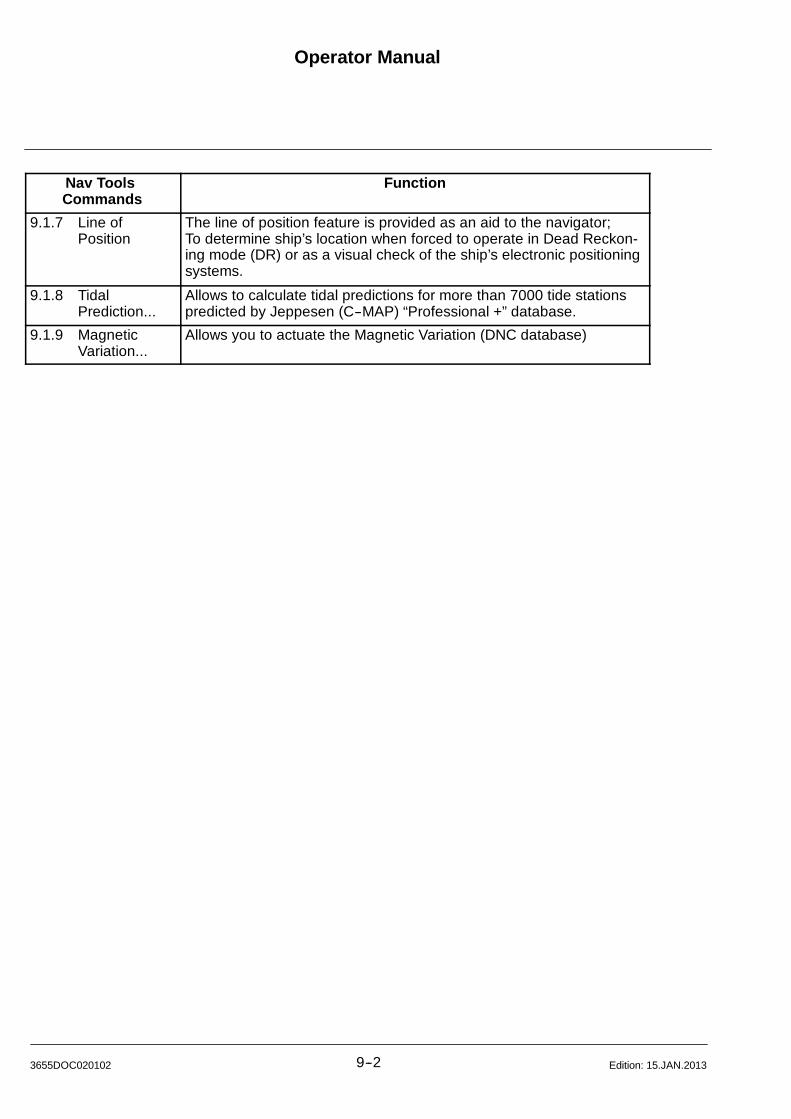
Operator Manual
9--23655DOC020102 Edition: 15.JAN.2013
Nav ToolsCommands
Function
9.1.7 Line ofPosition
The line of position feature is provided as an aid to the navigator;To determine ship’s location when forced to operate in Dead Reckon-ing mode (DR) or as a visual check of the ship’s electronic positioningsystems.
9.1.8 TidalPrediction...
Allows to calculate tidal predictions for more than 7000 tide stationspredicted by Jeppesen (C--MAP) “Professional +” database.
9.1.9 MagneticVariation...
Allows you to actuate the Magnetic Variation (DNC database)
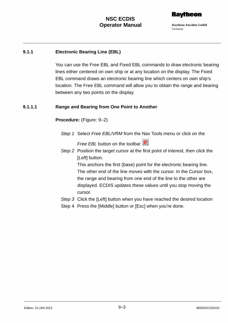
Operator Manual Raytheon Anschütz GmbHGermany
RNSC ECDIS
9--3 3655DOC020102Edition: 15.JAN.2013
9.1.1 Electronic Bearing Line (EBL)
You can use the Free EBL and Fixed EBL commands to draw electronic bearing
lines either centered on own ship or at any location on the display. The Fixed
EBL command draws an electronic bearing line which centers on own ship’s
location. The Free EBL command will allow you to obtain the range and bearing
between any two points on the display.
9.1.1.1 Range and Bearing from One Point to Another
Procedure: (Figure: 9--2)
Step 1 Select Free EBL/VRM from the Nav Tools menu or click on the
Free EBL button on the toolbar
Step 2 Position the target cursor at the first point of interest, then click the
[Left] button.
This anchors the first (base) point for the electronic bearing line.
The other end of the line moves with the cursor. In the Cursor box,
the range and bearing from one end of the line to the other are
displayed. ECDIS updates these values until you stop moving the
cursor.
Step 3 Click the [Left] button when you have reached the desired location
Step 4 Press the [Middle] button or [Esc] when you’re done.
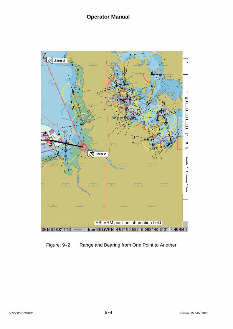
Operator Manual
9--43655DOC020102 Edition: 15.JAN.2013
EBLVRM position inhumation field
Step 2
Step 3
Figure: 9--2 Range and Bearing from One Point to Another
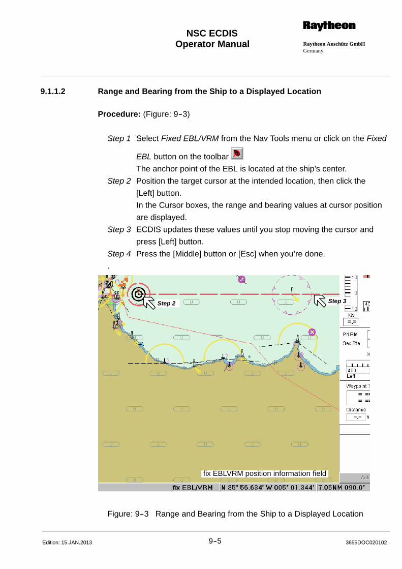
Operator Manual Raytheon Anschütz GmbHGermany
RNSC ECDIS
9--5 3655DOC020102Edition: 15.JAN.2013
9.1.1.2 Range and Bearing from the Ship to a Displayed Location
Procedure: (Figure: 9--3)
Step 1 Select Fixed EBL/VRM from the Nav Tools menu or click on the Fixed
EBL button on the toolbar
The anchor point of the EBL is located at the ship’s center.
Step 2 Position the target cursor at the intended location, then click the
[Left] button.
In the Cursor boxes, the range and bearing values at cursor position
are displayed.
Step 3 ECDIS updates these values until you stop moving the cursor and
press [Left] button.
Step 4 Press the [Middle] button or [Esc] when you’re done.
.
fix EBLVRM position information field
Step 2 Step 3
Figure: 9--3 Range and Bearing from the Ship to a Displayed Location
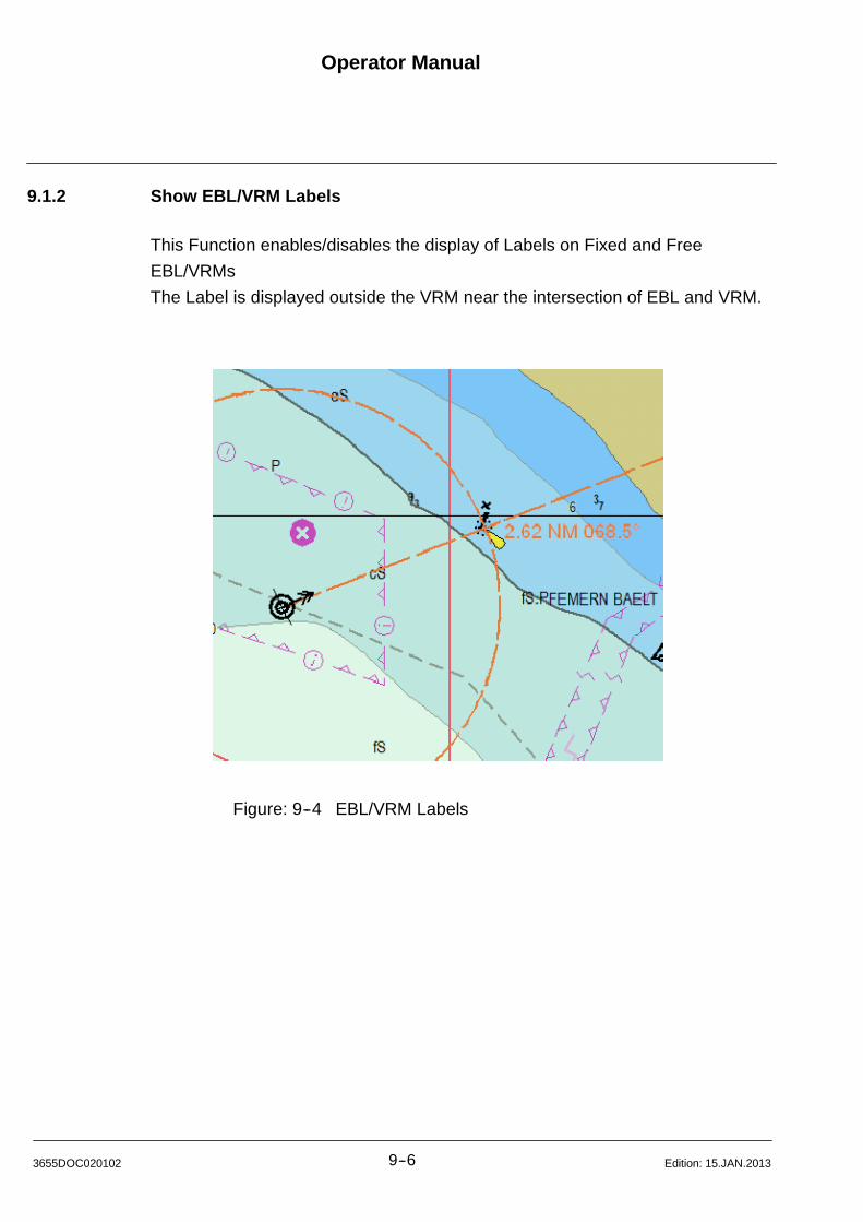
Operator Manual
9--63655DOC020102 Edition: 15.JAN.2013
9.1.2 Show EBL/VRM Labels
This Function enables/disables the display of Labels on Fixed and Free
EBL/VRMs
The Label is displayed outside the VRM near the intersection of EBL and VRM.
Figure: 9--4 EBL/VRM Labels

Operator Manual Raytheon Anschütz GmbHGermany
RNSC ECDIS
9--7 3655DOC020102Edition: 15.JAN.2013
9.1.3 Rhumb/Great Circle Line
Within this NavTool it is possible to calculat distances of two positions on a
Rhumb Line or a Great Circle Line.
Procedure: (Figure: 9--5)
Step 1 Select Rhumb/Great Circle Line from the Nav Tools menu.
The dialog box appears.
Step 2 Enter Start and End Coordinates. The bearings and distances are
calculated each time one of the coordinates is changed.
Step 3 Each of the lines may be shown on the chart by selecting the
corresponding check box.
Step 2
Step 3
Figure: 9--5 Line Tool

Operator Manual
9--83655DOC020102 Edition: 15.JAN.2013
9.1.4 Datum Transformation
With this NavTool it is possible to calculate position values (coordinates) for
different datums.
Procedure: (Figure: 9--6)
Step 1 Select Datum Transformation from the Nav Tools menu.
The dialog box appears.
Step 2 If you want to change the Source Datum, press the Change button,
a library list window appears.
Select another datum item from the list via cursor.
Press the OK button.
or If you want to change the Target Datum, press the Change button,
a library list window appears.
Select another Target item from the list via cursor.
Press the OK button.
Step 2
Figure: 9--6 Select a new Source Datum
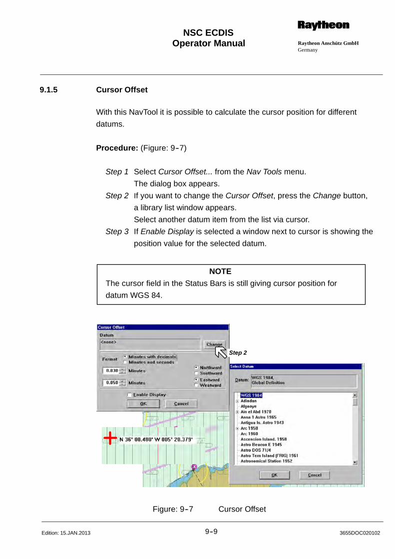
Operator Manual Raytheon Anschütz GmbHGermany
RNSC ECDIS
9--9 3655DOC020102Edition: 15.JAN.2013
9.1.5 Cursor Offset
With this NavTool it is possible to calculate the cursor position for different
datums.
Procedure: (Figure: 9--7)
Step 1 Select Cursor Offset... from the Nav Tools menu.
The dialog box appears.
Step 2 If you want to change the Cursor Offset, press the Change button,
a library list window appears.
Select another datum item from the list via cursor.
Step 3 If Enable Display is selected a window next to cursor is showing the
position value for the selected datum.
NOTE
The cursor field in the Status Bars is still giving cursor position for
datum WGS 84.
Step 2
Figure: 9--7 Cursor Offset
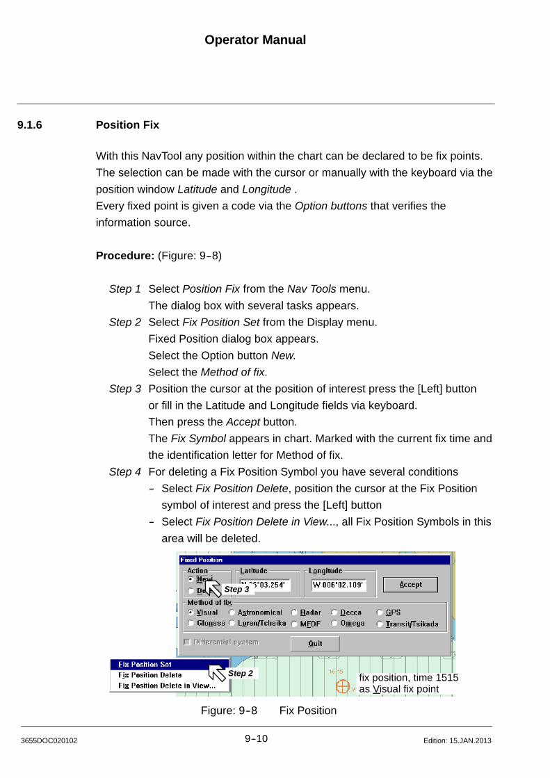
Operator Manual
9--103655DOC020102 Edition: 15.JAN.2013
9.1.6 Position Fix
With this NavTool any position within the chart can be declared to be fix points.
The selection can be made with the cursor or manually with the keyboard via the
position window Latitude and Longitude .
Every fixed point is given a code via the Option buttons that verifies the
information source.
Procedure: (Figure: 9--8)
Step 1 Select Position Fix from the Nav Tools menu.
The dialog box with several tasks appears.
Step 2 Select Fix Position Set from the Display menu.
Fixed Position dialog box appears.
Select the Option button New.
Select the Method of fix.
Step 3 Position the cursor at the position of interest press the [Left] button
or fill in the Latitude and Longitude fields via keyboard.
Then press the Accept button.
The Fix Symbol appears in chart. Marked with the current fix time and
the identification letter for Method of fix.
Step 4 For deleting a Fix Position Symbol you have several conditions
-- Select Fix Position Delete, position the cursor at the Fix Position
symbol of interest and press the [Left] button
-- Select Fix Position Delete in View..., all Fix Position Symbols in this
area will be deleted.
fix position, time 1515as Visual fix point
Step 2
Step 3
Figure: 9--8 Fix Position
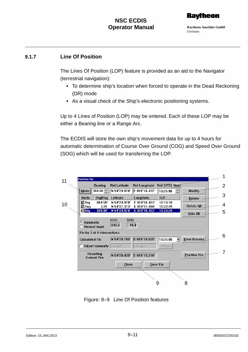
Operator Manual Raytheon Anschütz GmbHGermany
RNSC ECDIS
9--11 3655DOC020102Edition: 15.JAN.2013
9.1.7 Line Of Position
The Lines Of Position (LOP) feature is provided as an aid to the Navigator
(terrestrial navigation):
S To determine ship’s location when forced to operate in the Dead Reckoning
(DR) mode
S As a visual check of the Ship’s electronic positioning systems.
Up to 4 Lines of Position (LOP) may be entered. Each of these LOP may be
either a Bearing line or a Range Arc.
The ECDIS will store the own ship‘s movement data for up to 4 hours for
automatic determination of Course Over Ground (COG) and Speed Over Ground
(SOG) which will be used for transferring the LOP.
1
2
3
45
6
7
89
11
10
Figure: 9--9 Line Of Position features
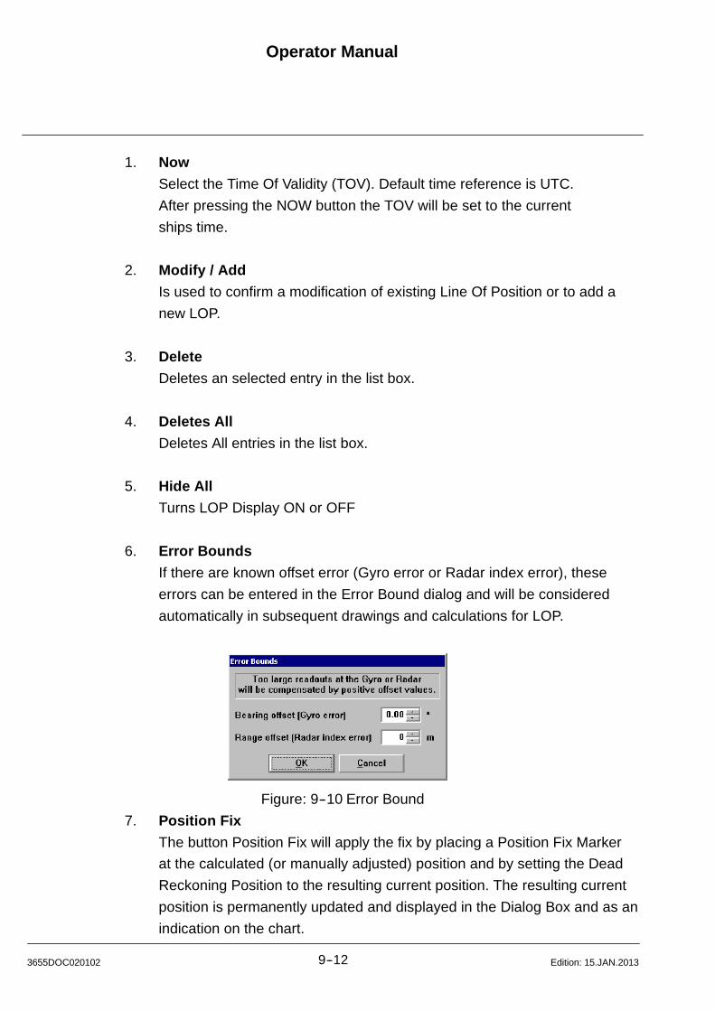
Operator Manual
9--123655DOC020102 Edition: 15.JAN.2013
1. Now
Select the Time Of Validity (TOV). Default time reference is UTC.
After pressing the NOW button the TOV will be set to the current
ships time.
2. Modify / Add
Is used to confirm a modification of existing Line Of Position or to add a
new LOP.
3. Delete
Deletes an selected entry in the list box.
4. Deletes All
Deletes All entries in the list box.
5. Hide All
Turns LOP Display ON or OFF
6. Error Bounds
If there are known offset error (Gyro error or Radar index error), these
errors can be entered in the Error Bound dialog and will be considered
automatically in subsequent drawings and calculations for LOP.
Figure: 9--10 Error Bound
7. Position Fix
The button Position Fix will apply the fix by placing a Position Fix Marker
at the calculated (or manually adjusted) position and by setting the Dead
Reckoning Position to the resulting current position. The resulting current
position is permanently updated and displayed in the Dialog Box and as an
indication on the chart.
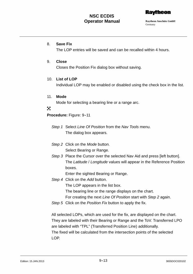
Operator Manual Raytheon Anschütz GmbHGermany
RNSC ECDIS
9--13 3655DOC020102Edition: 15.JAN.2013
8. Save Fix
The LOP entries will be saved and can be recalled within 4 hours.
9. CloseCloses the Position Fix dialog box without saving.
10. List of LOP
Individual LOP may be enabled or disabled using the check box in the list.
11. Mode
Mode for selecting a bearing line or a range arc.
Procedure: Figure: 9--11
Step 1 Select Line Of Position from the Nav Tools menu.
The dialog box appears.
Step 2 Click on the Mode button.
Select Bearing or Range.
Step 3 Place the Cursor over the selected Nav Aid and press [left button].
The Latitude / Longitude values will appear in the Reference Position
boxes.
Enter the sighted Bearing or Range.
Step 4 Click on the Add button.
The LOP appears in the list box.
The bearing line or the range displays on the chart.
For creating the next Line Of Position start with Step 2 again.
Step 5 Click on the Position Fix button to apply the fix.
All selected LOPs, which are used for the fix, are displayed on the chart.
They are labeled with their Bearing or Range and the ToV. Transferred LPO
are labeled with “TPL” (Transferred Position Line) additionally.
The fixed will be calculated from the intersection points of the selected
LOP.
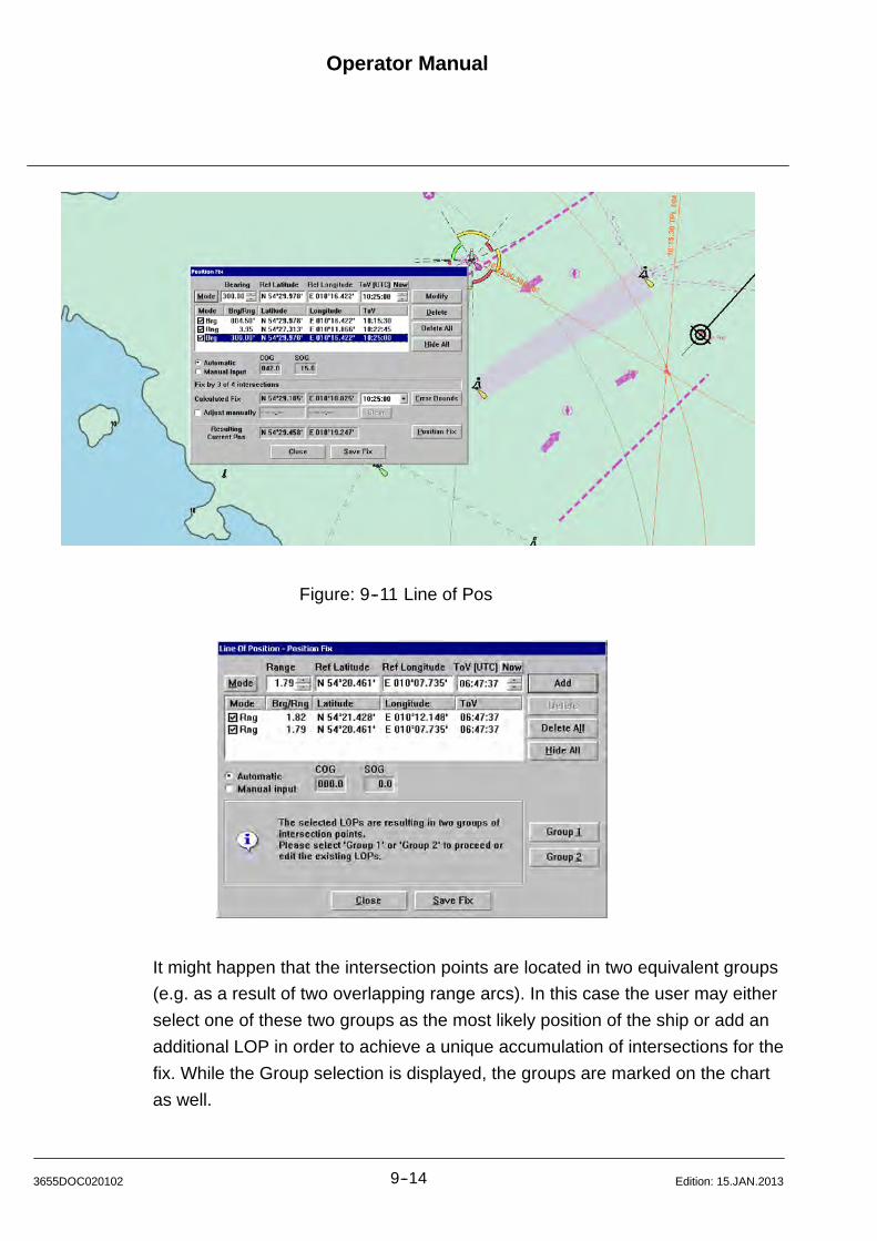
Operator Manual
9--143655DOC020102 Edition: 15.JAN.2013
Figure: 9--11 Line of Pos
It might happen that the intersection points are located in two equivalent groups
(e.g. as a result of two overlapping range arcs). In this case the user may either
select one of these two groups as the most likely position of the ship or add an
additional LOP in order to achieve a unique accumulation of intersections for the
fix. While the Group selection is displayed, the groups are marked on the chart
as well.
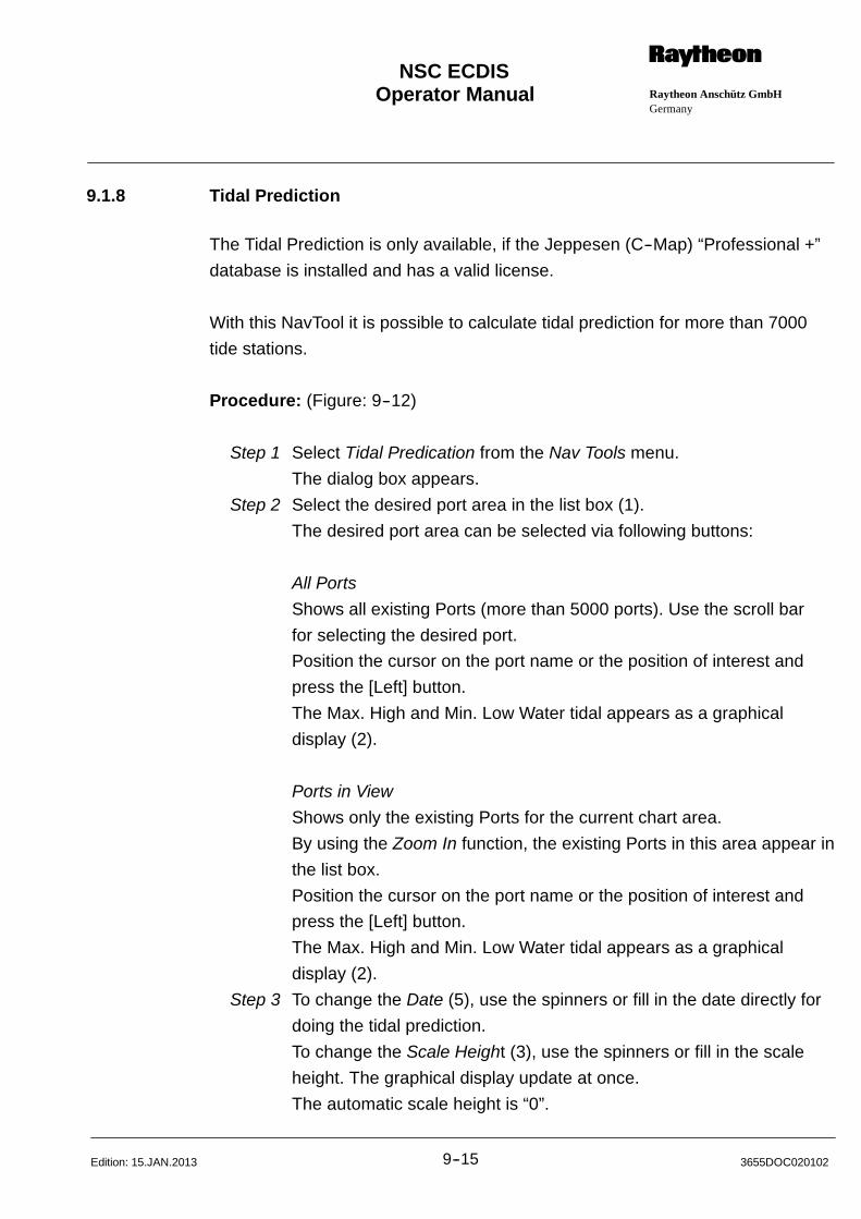
Operator Manual Raytheon Anschütz GmbHGermany
RNSC ECDIS
9--15 3655DOC020102Edition: 15.JAN.2013
9.1.8 Tidal Prediction
The Tidal Prediction is only available, if the Jeppesen (C--Map) “Professional +”
database is installed and has a valid license.
With this NavTool it is possible to calculate tidal prediction for more than 7000
tide stations.
Procedure: (Figure: 9--12)
Step 1 Select Tidal Predication from the Nav Tools menu.
The dialog box appears.
Step 2 Select the desired port area in the list box (1).
The desired port area can be selected via following buttons:
All Ports
Shows all existing Ports (more than 5000 ports). Use the scroll bar
for selecting the desired port.
Position the cursor on the port name or the position of interest and
press the [Left] button.
The Max. High and Min. Low Water tidal appears as a graphical
display (2).
Ports in View
Shows only the existing Ports for the current chart area.
By using the Zoom In function, the existing Ports in this area appear in
the list box.
Position the cursor on the port name or the position of interest and
press the [Left] button.
The Max. High and Min. Low Water tidal appears as a graphical
display (2).
Step 3 To change the Date (5), use the spinners or fill in the date directly for
doing the tidal prediction.
To change the Scale Height (3), use the spinners or fill in the scale
height. The graphical display update at once.
The automatic scale height is “0”.
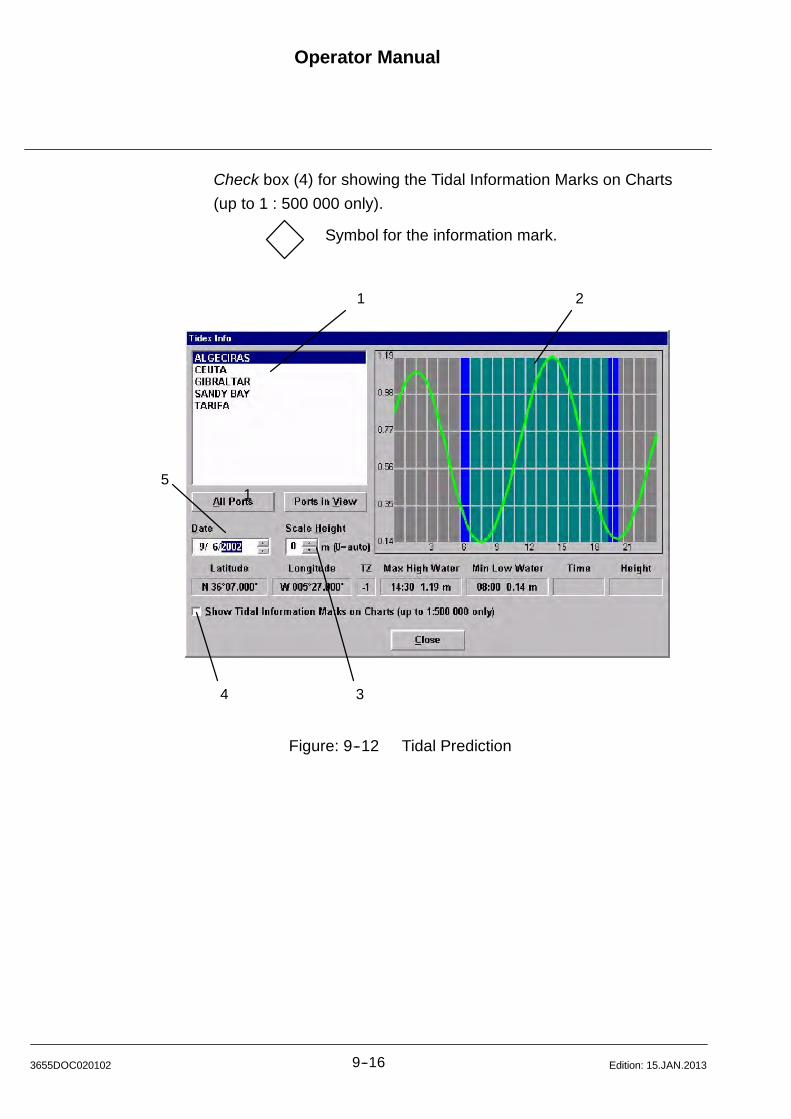
Operator Manual
9--163655DOC020102 Edition: 15.JAN.2013
Check box (4) for showing the Tidal Information Marks on Charts
(up to 1 : 500 000 only).
Symbol for the information mark.
1 2
51
4 3
Figure: 9--12 Tidal Prediction
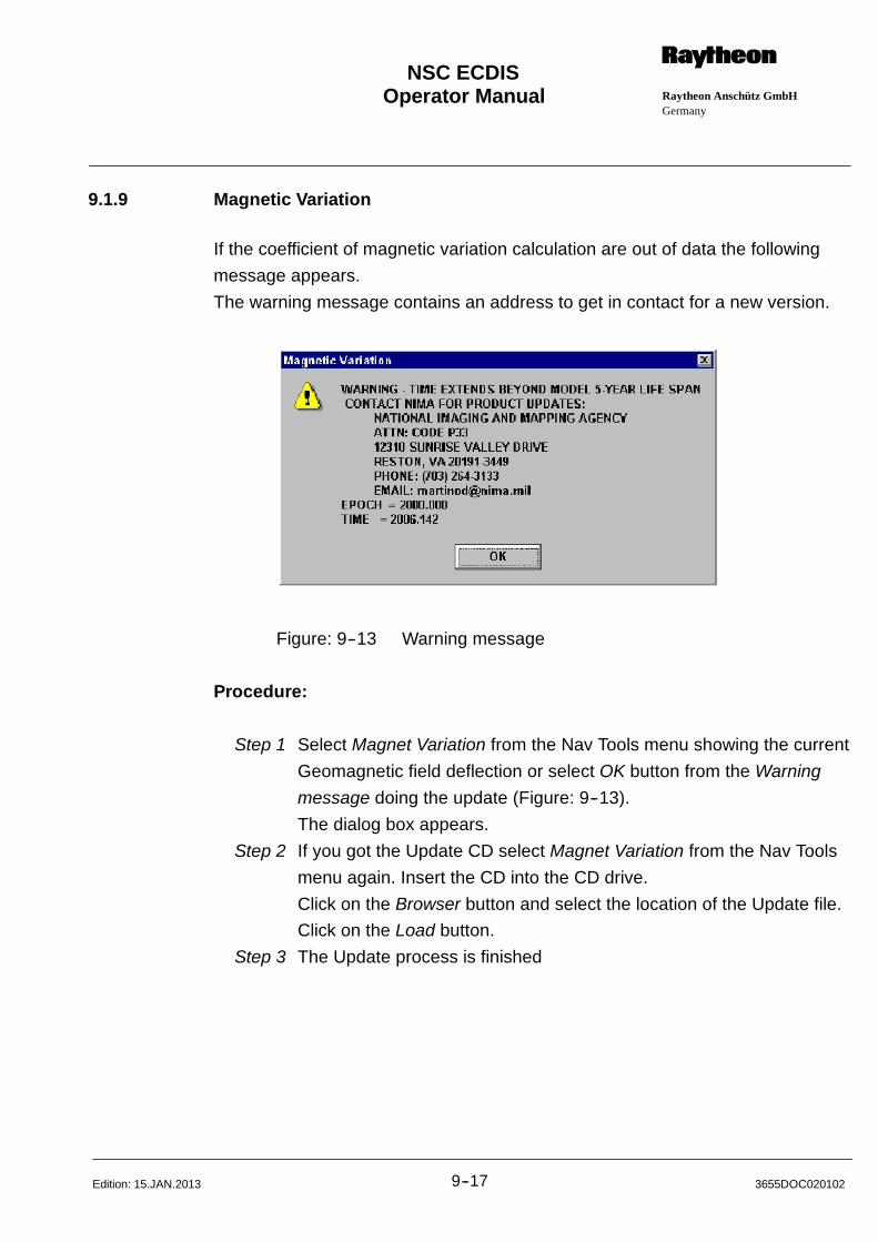
Operator Manual Raytheon Anschütz GmbHGermany
RNSC ECDIS
9--17 3655DOC020102Edition: 15.JAN.2013
9.1.9 Magnetic Variation
If the coefficient of magnetic variation calculation are out of data the following
message appears.
The warning message contains an address to get in contact for a new version.
Figure: 9--13 Warning message
Procedure:
Step 1 Select Magnet Variation from the Nav Tools menu showing the current
Geomagnetic field deflection or select OK button from the Warning
message doing the update (Figure: 9--13).
The dialog box appears.
Step 2 If you got the Update CD select Magnet Variation from the Nav Tools
menu again. Insert the CD into the CD drive.
Click on the Browser button and select the location of the Update file.
Click on the Load button.
Step 3 The Update process is finished
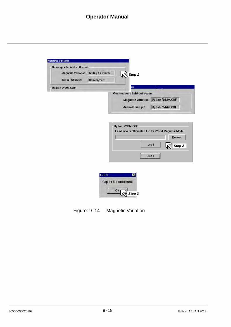
Operator Manual
9--183655DOC020102 Edition: 15.JAN.2013
Step 1
Step 2
Step 3
Figure: 9--14 Magnetic Variation
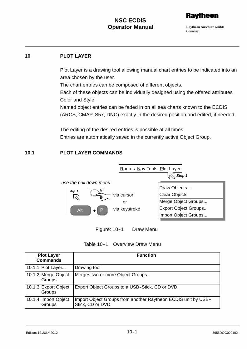
Operator Manual Raytheon Anschütz GmbHGermany
RNSC ECDIS
10--1 3655DOC020102Edition: 12.JULY.2012
10 PLOT LAYER
Plot Layer is a drawing tool allowing manual chart entries to be indicated into an
area chosen by the user.
The chart entries can be composed of different objects.
Each of these objects can be individually designed using the offered attributes
Color and Style.
Named object entries can be faded in on all sea charts known to the ECDIS
(ARCS, CMAP, S57, DNC) exactly in the desired position and edited, if needed.
The editing of the desired entries is possible at all times.
Entries are automatically saved in the currently active Object Group.
10.1 PLOT LAYER COMMANDS
Alt P
via cursor
via keystroke
or
+
use the pull down menu
Step 1
Routes Nav Tools Plot Layer
Draw Objects...
Clear Objects
Merge Object Groups...
Export Object Groups...
Import Object Groups...
left
Figure: 10--1 Draw Menu
Table 10--1 Overview Draw Menu
Plot LayerCommands
Function
10.1.1 Plot Layer... Drawing tool
10.1.2 Merge ObjectGroups
Merges two or more Object Groups.
10.1.3 Export ObjectGroups
Export Object Groups to a USB--Stick, CD or DVD.
10.1.4 Import ObjectGroups
Import Object Groups from another Raytheon ECDIS unit by USB--Stick, CD or DVD.
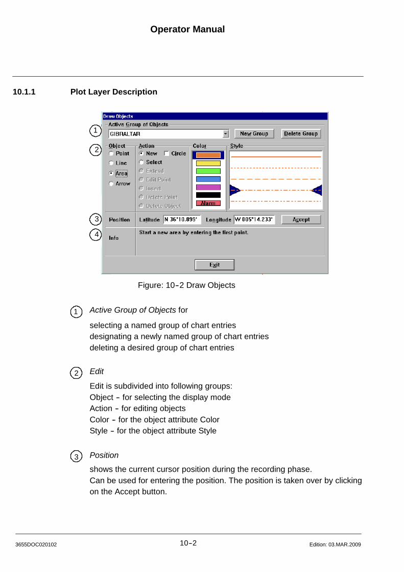
Operator Manual
10--23655DOC020102 Edition: 03.MAR.2009
10.1.1 Plot Layer Description
1
2
3
4
Figure: 10--2 Draw Objects
1 Active Group of Objects for
selecting a named group of chart entriesdesignating a newly named group of chart entriesdeleting a desired group of chart entries
2 Edit
Edit is subdivided into following groups:Object -- for selecting the display modeAction -- for editing objectsColor -- for the object attribute ColorStyle -- for the object attribute Style
3 Position
shows the current cursor position during the recording phase.Can be used for entering the position. The position is taken over by clickingon the Accept button.

Operator Manual Raytheon Anschütz GmbHGermany
RNSC ECDIS
10--3 3655DOC020102Edition: 03.MAR.2009
4 Info
shows context--related information or
shows the known data of an object group (name, last modified, contents).
How it works
S Info for Object Point selection
Each point can be marked with a label (font size Small, Middle, Large), Color
and Style.
The labeling can be done:
-- manually (e.g. name)
-- automatically by using the selection mode UTC (Universal Time Clock)
or Sequential
S Info for Object Line selection
A line can be displayed as a line or a circle (check box selection).
The Line or Circle can be marked in Color and Style.
In the Circle selection mode, the Radius and the Number of intermediate
points will be determined by entering the respective values into an additional
dialog box.
S Info for Object Area selection (3 points minimum)
An area consists of 3 points minimum.
An area can also be displayed as a circle (1 point). In this selection mode, the
Radius and the Number of intermediate points will be determined by entering
the respective values into an additional dialog box.
S Info for Object Arrow selection (2 points minimum)
Each arrow can be marked with a label (font size Small, Middle, Large) Color
and Style.
The labeling can be done:.
-- manually (e.g. name), bearing and distance is selectable.
-- automatically via NLT (Not Less Than) or NMT (Not More Than) with
bearing. As an example, this functionality can be used to mark the bound
aries of safe and unsafe fairways.
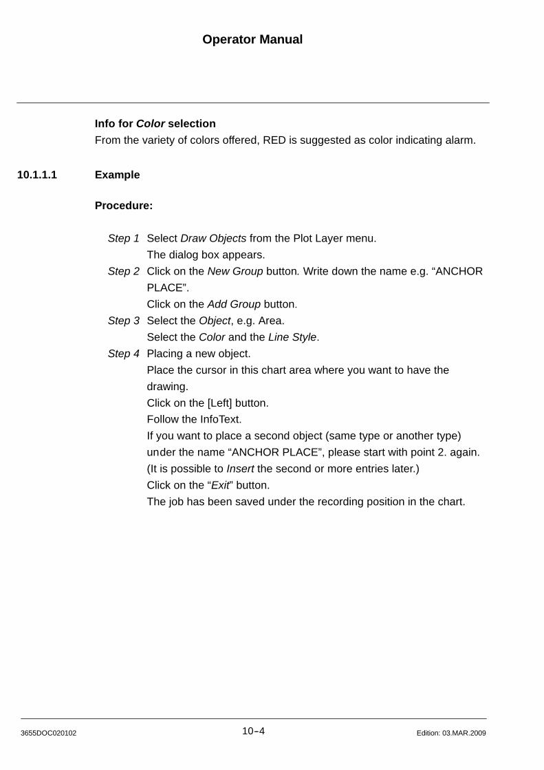
Operator Manual
10--43655DOC020102 Edition: 03.MAR.2009
Info for Color selection
From the variety of colors offered, RED is suggested as color indicating alarm.
10.1.1.1 Example
Procedure:
Step 1 Select Draw Objects from the Plot Layer menu.
The dialog box appears.
Step 2 Click on the New Group button. Write down the name e.g. “ANCHOR
PLACE”.
Click on the Add Group button.
Step 3 Select the Object, e.g. Area.
Select the Color and the Line Style.
Step 4 Placing a new object.
Place the cursor in this chart area where you want to have the
drawing.
Click on the [Left] button.
Follow the InfoText.
If you want to place a second object (same type or another type)
under the name “ANCHOR PLACE”, please start with point 2. again.
(It is possible to Insert the second or more entries later.)
Click on the “Exit” button.
The job has been saved under the recording position in the chart.
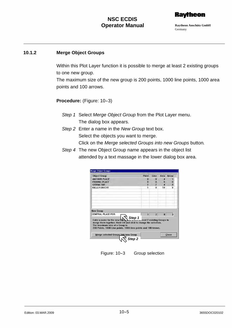
Operator Manual Raytheon Anschütz GmbHGermany
RNSC ECDIS
10--5 3655DOC020102Edition: 03.MAR.2009
10.1.2 Merge Object Groups
Within this Plot Layer function it is possible to merge at least 2 existing groups
to one new group.
The maximum size of the new group is 200 points, 1000 line points, 1000 area
points and 100 arrows.
Procedure: (Figure: 10--3)
Step 1 Select Merge Object Group from the Plot Layer menu.
The dialog box appears.
Step 2 Enter a name in the New Group text box.
Select the objects you want to merge.
Click on the Merge selected Groups into new Groups button.
Step 4 The new Object Group name appears in the object list
attended by a text massage in the lower dialog box area.
Step 2
Step 1
Figure: 10--3 Group selection

Operator Manual
10--63655DOC020102 Edition: 12.JULY.2012
10.1.3 Export Object Groups
The Export Object Groups command allows you to save groups on a USB--Stick,
CD or DVD.
Procedure: (Figure: 10--4)
Step 1 Select Export Object Group from the Plot Layer menu.
The dialog box appears displaying the names of all the object groups
saved in the list.
Step 2 Select a name of the object you want to export.
Step 3 Insert a Floppy into the drive and click on the Export to Floppy button.
The dialog box remains open for you to copy additional objects.
Click on Close when you are done.
Step 3
Step 2
Step 3
Step 2
Figure: 10--4 Export Object dialog box
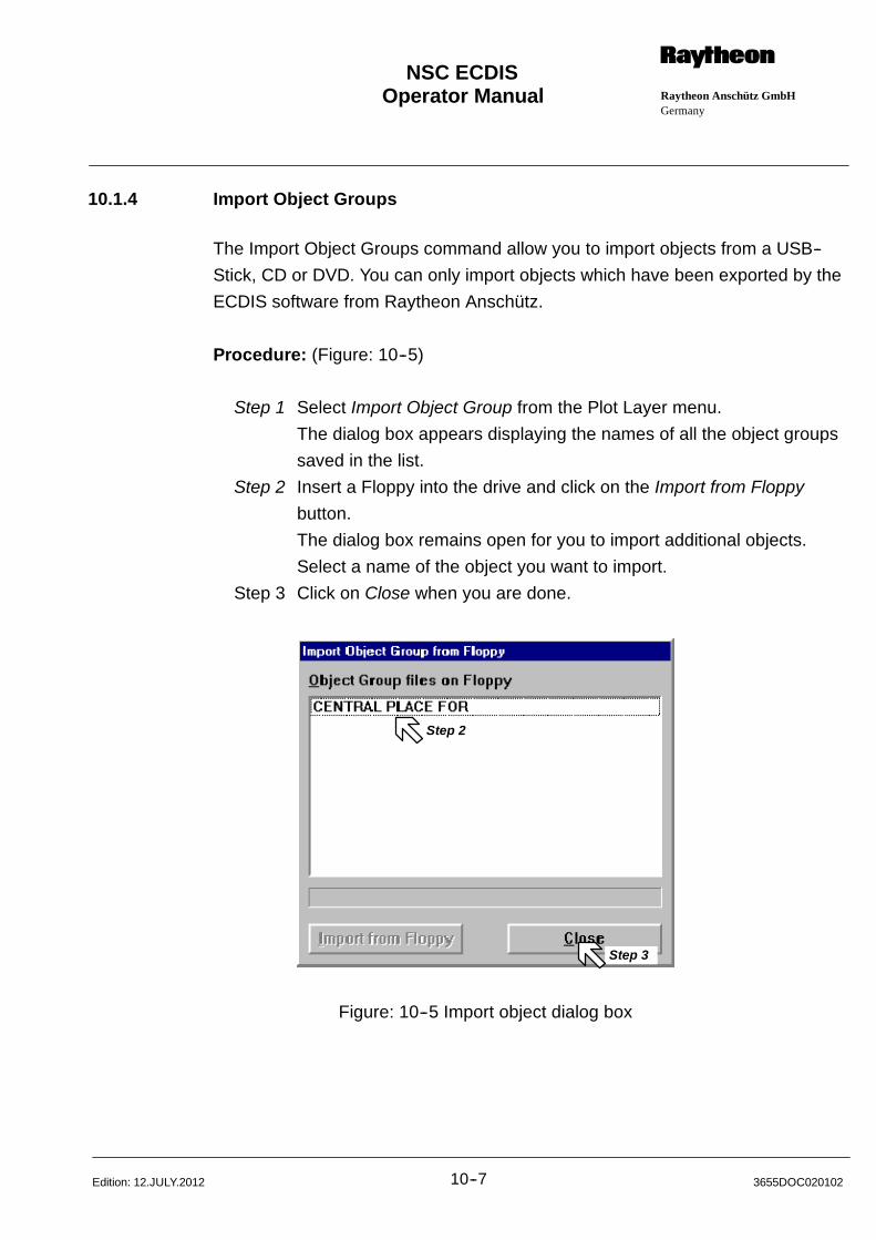
Operator Manual Raytheon Anschütz GmbHGermany
RNSC ECDIS
10--7 3655DOC020102Edition: 12.JULY.2012
10.1.4 Import Object Groups
The Import Object Groups command allow you to import objects from a USB--
Stick, CD or DVD. You can only import objects which have been exported by the
ECDIS software from Raytheon Anschütz.
Procedure: (Figure: 10--5)
Step 1 Select Import Object Group from the Plot Layer menu.
The dialog box appears displaying the names of all the object groups
saved in the list.
Step 2 Insert a Floppy into the drive and click on the Import from Floppy
button.
The dialog box remains open for you to import additional objects.
Select a name of the object you want to import.
Step 3 Click on Close when you are done.
Step 3
Step 2
Figure: 10--5 Import object dialog box

Operator Manual
10--83655DOC020102 Edition: 03.MAR.2009
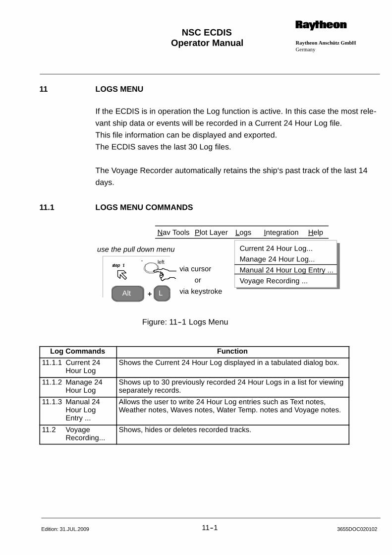
Operator Manual Raytheon Anschütz GmbHGermany
RNSC ECDIS
11--1 3655DOC020102Edition: 31.JUL.2009
11 LOGS MENU
If the ECDIS is in operation the Log function is active. In this case the most rele-
vant ship data or events will be recorded in a Current 24 Hour Log file.
This file information can be displayed and exported.
The ECDIS saves the last 30 Log files.
The Voyage Recorder automatically retains the ship‘s past track of the last 14
days.
11.1 LOGS MENU COMMANDS
Alt L
via cursor
via keystroke
or
+
use the pull down menu
Nav Tools Logs Integration Help
Current 24 Hour Log...
Manage 24 Hour Log...
Manual 24 Hour Log Entry ...
Voyage Recording ...
Plot Layer
left
Figure: 11--1 Logs Menu
Log Commands Function
11.1.1 Current 24Hour Log
Shows the Current 24 Hour Log displayed in a tabulated dialog box.
11.1.2 Manage 24Hour Log
Shows up to 30 previously recorded 24 Hour Logs in a list for viewingseparately records.
11.1.3 Manual 24Hour LogEntry ...
Allows the user to write 24 Hour Log entries such as Text notes,Weather notes, Waves notes, Water Temp. notes and Voyage notes.
11.2 VoyageRecording...
Shows, hides or deletes recorded tracks.
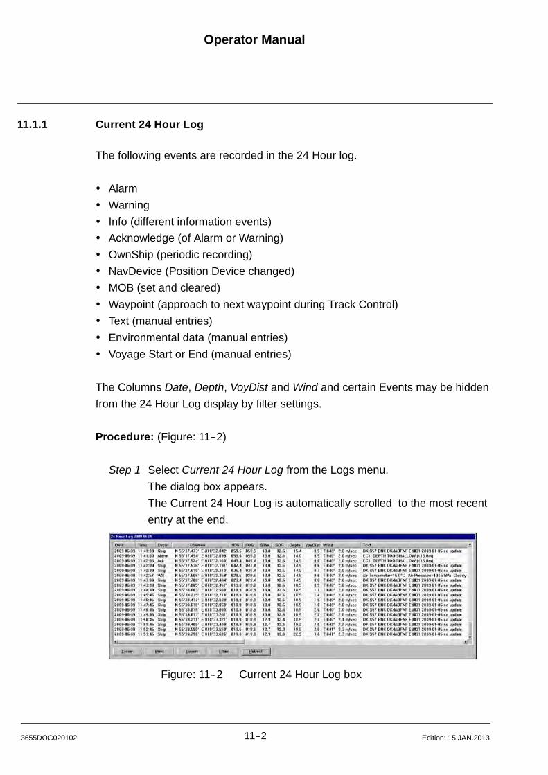
Operator Manual
11--23655DOC020102 Edition: 15.JAN.2013
11.1.1 Current 24 Hour Log
The following events are recorded in the 24 Hour log.
Alarm
Warning
Info (different information events)
Acknowledge (of Alarm or Warning)
OwnShip (periodic recording)
NavDevice (Position Device changed)
MOB (set and cleared)
Waypoint (approach to next waypoint during Track Control)
Text (manual entries)
Environmental data (manual entries)
Voyage Start or End (manual entries)
The Columns Date, Depth, VoyDist and Wind and certain Events may be hidden
from the 24 Hour Log display by filter settings.
Procedure: (Figure: 11--2)
Step 1 Select Current 24 Hour Log from the Logs menu.
The dialog box appears.
The Current 24 Hour Log is automatically scrolled to the most recent
entry at the end.
Figure: 11--2 Current 24 Hour Log box
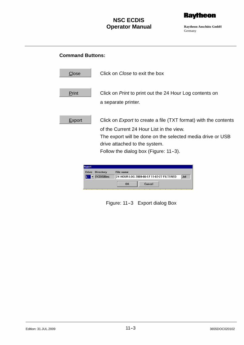
Operator Manual Raytheon Anschütz GmbHGermany
RNSC ECDIS
11--3 3655DOC020102Edition: 31.JUL.2009
Command Buttons:
Close Click on Close to exit the box
Print Click on Print to print out the 24 Hour Log contents on
a separate printer.
Export Click on Export to create a file (TXT format) with the contents
of the Current 24 Hour List in the view.
The export will be done on the selected media drive or USB
drive attached to the system.
Follow the dialog box (Figure: 11--3).
Figure: 11--3 Export dialog Box
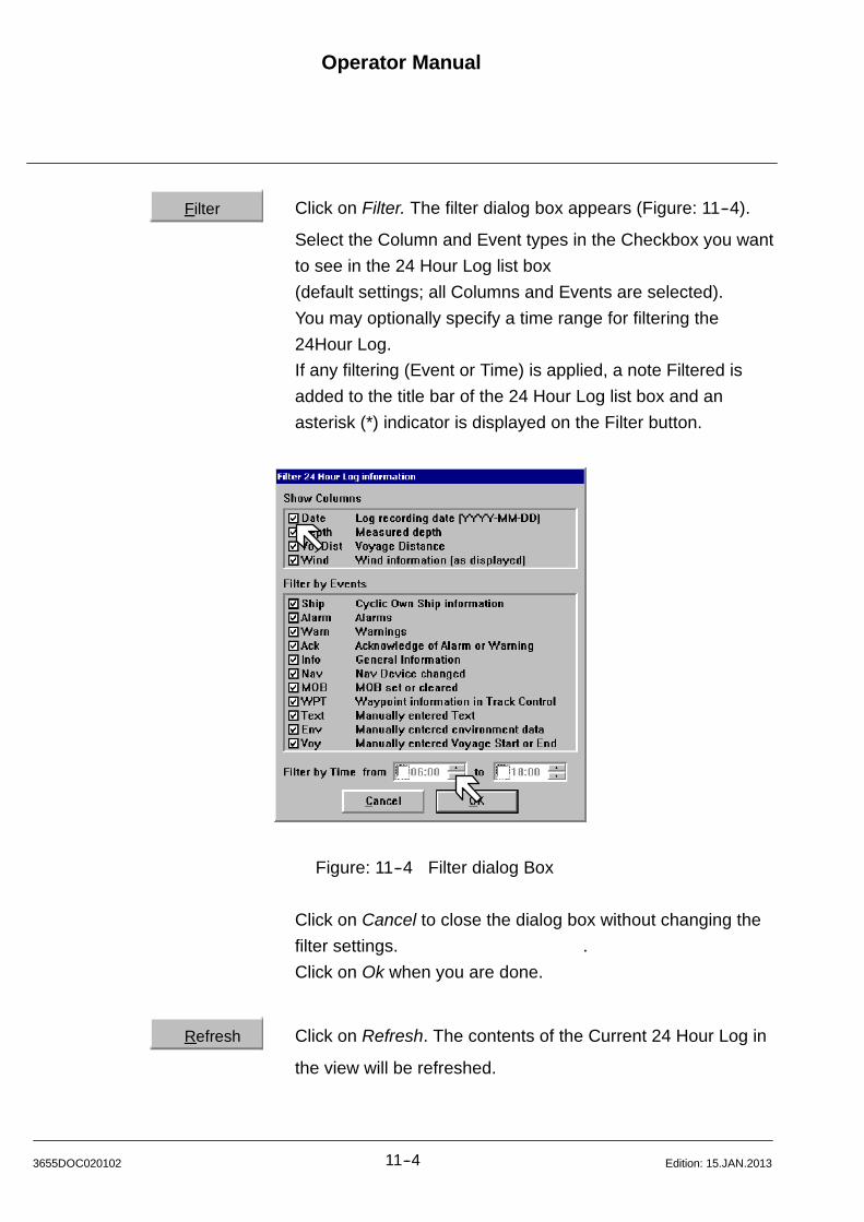
Operator Manual
11--43655DOC020102 Edition: 15.JAN.2013
Filter Click on Filter. The filter dialog box appears (Figure: 11--4).
Select the Column and Event types in the Checkbox you want
to see in the 24 Hour Log list box
(default settings; all Columns and Events are selected).
You may optionally specify a time range for filtering the
24Hour Log.
If any filtering (Event or Time) is applied, a note Filtered is
added to the title bar of the 24 Hour Log list box and an
asterisk (*) indicator is displayed on the Filter button.
Figure: 11--4 Filter dialog Box
Click on Cancel to close the dialog box without changing the
filter settings. .
Click on Ok when you are done.
Refresh Click on Refresh. The contents of the Current 24 Hour Log in
the view will be refreshed.
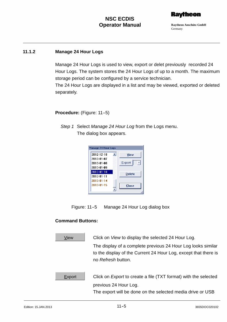
Operator Manual Raytheon Anschütz GmbHGermany
RNSC ECDIS
11--5 3655DOC020102Edition: 15.JAN.2013
11.1.2 Manage 24 Hour Logs
Manage 24 Hour Logs is used to view, export or delet previously recorded 24
Hour Logs. The system stores the 24 Hour Logs of up to a month. The maximum
storage period can be configured by a service technician.
The 24 Hour Logs are displayed in a list and may be viewed, exported or deleted
separately.
Procedure: (Figure: 11--5)
Step 1 Select Manage 24 Hour Log from the Logs menu.
The dialog box appears.
Figure: 11--5 Manage 24 Hour Log dialog box
Command Buttons:
View Click on View to display the selected 24 Hour Log.
The display of a complete previous 24 Hour Log looks similar
to the display of the Current 24 Hour Log, except that there is
no Refresh button.
Export Click on Export to create a file (TXT format) with the selected
previous 24 Hour Log.
The export will be done on the selected media drive or USB

Operator Manual
11--63655DOC020102 Edition: 15.JAN.2013
drive attached to the system.
Follow the dialog box (Figure: 11--6).
NOTE
After exporting, the user may choose to delete the exported logs.
Figure: 11--6 Export dialog Box
Delete Click on Delete to delete a selected 24 Hour Log entry.
NOTE
The 24 Hour Logs of the current and the previous day are protected
and may not be deleted. The protected 24Hour Logs are displayed in
dark red.
A larger number of protected 24Hour--Logs may be configured.
Close Click on Close to exit the box.
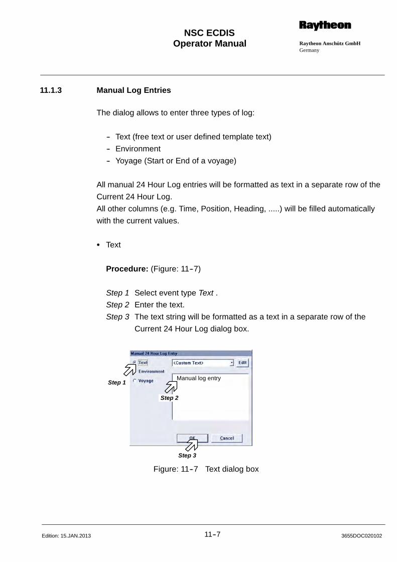
Operator Manual Raytheon Anschütz GmbHGermany
RNSC ECDIS
11--7 3655DOC020102Edition: 15.JAN.2013
11.1.3 Manual Log Entries
The dialog allows to enter three types of log:
-- Text (free text or user defined template text)
-- Environment
-- Yoyage (Start or End of a voyage)
All manual 24 Hour Log entries will be formatted as text in a separate row of the
Current 24 Hour Log.
All other columns (e.g. Time, Position, Heading, .....) will be filled automatically
with the current values.
S Text
Procedure: (Figure: 11--7)
Step 1 Select event type Text .
Step 2 Enter the text.
Step 3 The text string will be formatted as a text in a separate row of the
Current 24 Hour Log dialog box.
Step 1
Step 2
Step 3
Manual log entry
Figure: 11--7 Text dialog box
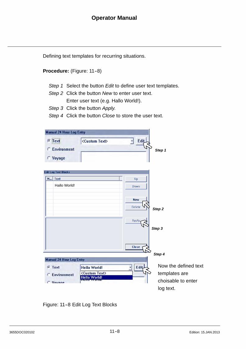
Operator Manual
11--83655DOC020102 Edition: 15.JAN.2013
Defining text templates for recurring situations.
Procedure: (Figure: 11--8)
Step 1 Select the button Edit to define user text templates.
Step 2 Click the button New to enter user text.
Enter user text (e.g. Hallo World!).
Step 3 Click the button Apply.
Step 4 Click the button Close to store the user text.
Step 2
Step 3
Hallo World!
Step 1
Step 4
Now the defined text
templates are
choisable to enter
log text.
Figure: 11--8 Edit Log Text Blocks

Operator Manual Raytheon Anschütz GmbHGermany
RNSC ECDIS
11--9 3655DOC020102Edition: 15.JAN.2013
S Environment Entry
Procedure: (Figure: 11--9)
Step 1 Select event type Environment
Step 2 Enter the values for Air Temperature, Air Pressure, Water Temerature,
Wave Height, Wave Direction, Visibility, Coverage. The ’C’ button will
clear the corresponding field.
Step 3 The text string will be formatted as a text in a separate row of the
Current 24 Hour Log dialog box.
Step 1
Step 2
Step 3
Figure: 11--9 Manual 24 Hour Log Entry
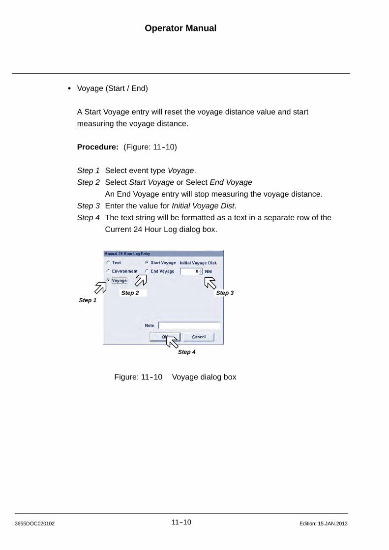
Operator Manual
11--103655DOC020102 Edition: 15.JAN.2013
S Voyage (Start / End)
A Start Voyage entry will reset the voyage distance value and start
measuring the voyage distance.
Procedure: (Figure: 11--10)
Step 1 Select event type Voyage.
Step 2 Select Start Voyage or Select End Voyage
An End Voyage entry will stop measuring the voyage distance.
Step 3 Enter the value for Initial Voyage Dist.
Step 4 The text string will be formatted as a text in a separate row of the
Current 24 Hour Log dialog box.
Step 1Step 3
Step 4
Step 2
Figure: 11--10 Voyage dialog box

Operator Manual Raytheon Anschütz GmbHGermany
RNSC ECDIS
11--11 3655DOC020102Edition: 03.MAR.2009
11.1.4 Voyage Recording
The Voyage Recorder automatically retains the ship‘s past track of the last 14
days.
This record is registered in the Recorded Track area of the Voyage Recording
box using the UTC data of the record as reference name.
These registrations will loose their Write--protect--mark “P” after 14 days.
The latest registration is displayed as the button line of the Recorded Tracks
area.
Procedure: (Figure: 11--11)
Step 1 Select Voyage Recording from the Logs menu.
The dialog box appears.
Figure: 11--11 Recorder track

Operator Manual
11--123655DOC020102 Edition: 03.MAR.2009
Position Receiver:
This List box contains the integrated Position Receivers.
Selection is performed either via the scroll bar or directly via the cursor.
While plotting the trail type of position receiver is indicated at each interval
mark.
Time marker interval:
This entry determines the Labeling intervals in minutes.
While plotting the trail each section is marked with a time label.
Display the Recorded Tracks:
To display the recorded tracks select the desired track via cursor from the
Recorded Tracks list.
Command Buttons:
Show The recorded track is superimposed on the chart. As a recorded
track may be some weeks old it’s location has to be looked up
manually if you want to see it on the screen zoom out as far as
necessary and look for the recorded track, then zoom in the
selected trail
Hide The recorded track is removed from display.
Delete Deletes recorded tracks.
Besides automatic registration of all ship‘ s navigation data, the ships‘ s position
can additionally be marked using the Mark at Ship function (see chapter 7.1.7).
This event will also be listed in the Recorded Tracks list and be marked with an
asterisk if the Show user defined ship marker Mark at Ship check box is acti-
vated.
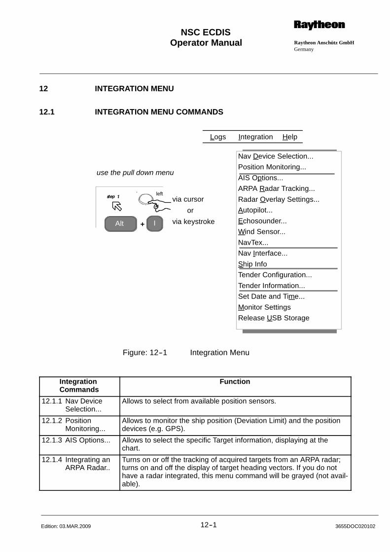
Operator Manual Raytheon Anschütz GmbHGermany
RNSC ECDIS
12--1 3655DOC020102Edition: 03.MAR.2009
12 INTEGRATION MENU
12.1 INTEGRATION MENU COMMANDS
Nav Device Selection...
Position Monitoring...
AIS Options...
ARPA Radar Tracking...
Radar Overlay Settings...
Autopilot...
Echosounder...
Wind Sensor...
NavTex...
Nav Interface...
Ship Info
Tender Configuration...
Tender Information...
Set Date and Time...
Monitor Settings
Release USB Storage
Alt I
via cursor
via keystroke
or
+
use the pull down menu
Logs Integration Help
left
Figure: 12--1 Integration Menu
IntegrationCommands
Function
12.1.1 Nav DeviceSelection...
Allows to select from available position sensors.
12.1.2 PositionMonitoring...
Allows to monitor the ship position (Deviation Limit) and the positiondevices (e.g. GPS).
12.1.3 AIS Options... Allows to select the specific Target information, displaying at thechart.
12.1.4 Integrating anARPA Radar..
Turns on or off the tracking of acquired targets from an ARPA radar;turns on and off the display of target heading vectors. If you do nothave a radar integrated, this menu command will be grayed (not avail-able).
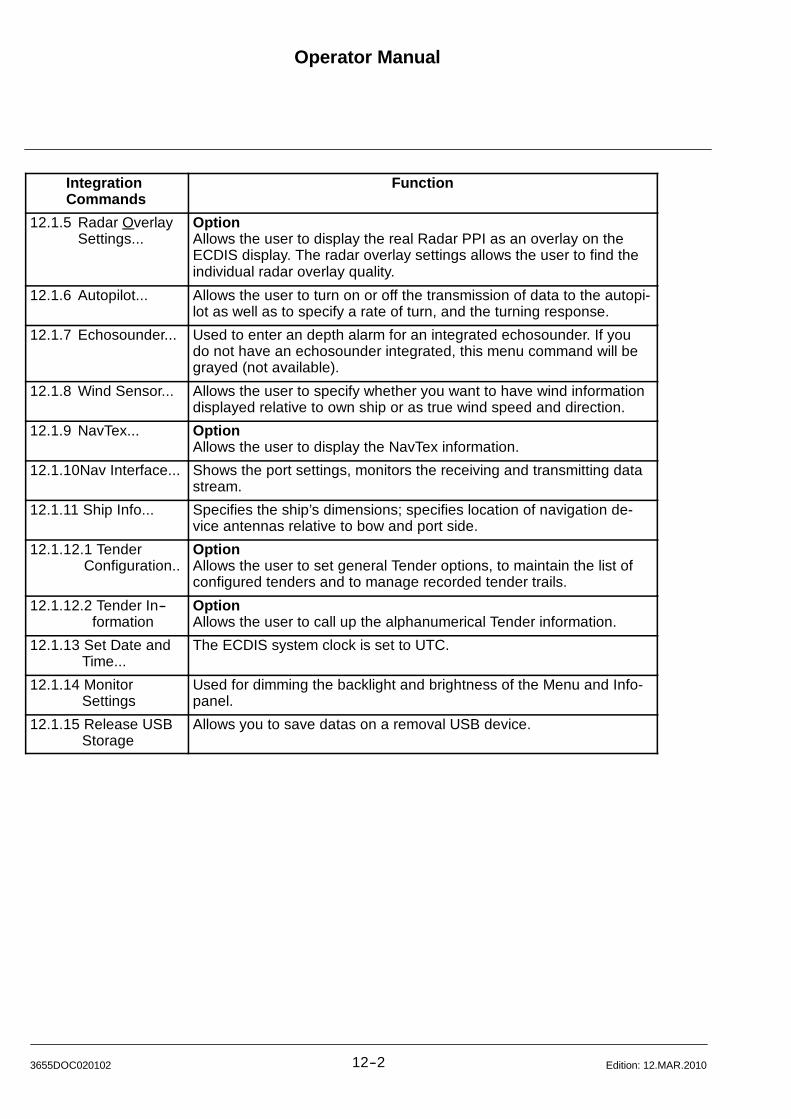
Operator Manual
12--23655DOC020102 Edition: 12.MAR.2010
IntegrationCommands
Function
12.1.5 Radar OverlaySettings...
OptionAllows the user to display the real Radar PPI as an overlay on theECDIS display. The radar overlay settings allows the user to find theindividual radar overlay quality.
12.1.6 Autopilot... Allows the user to turn on or off the transmission of data to the autopi-lot as well as to specify a rate of turn, and the turning response.
12.1.7 Echosounder... Used to enter an depth alarm for an integrated echosounder. If youdo not have an echosounder integrated, this menu command will begrayed (not available).
12.1.8 Wind Sensor... Allows the user to specify whether you want to have wind informationdisplayed relative to own ship or as true wind speed and direction.
12.1.9 NavTex... OptionAllows the user to display the NavTex information.
12.1.10Nav Interface... Shows the port settings, monitors the receiving and transmitting datastream.
12.1.11 Ship Info... Specifies the ship’s dimensions; specifies location of navigation de-vice antennas relative to bow and port side.
12.1.12.1 TenderConfiguration..
OptionAllows the user to set general Tender options, to maintain the list ofconfigured tenders and to manage recorded tender trails.
12.1.12.2 Tender In--formation
OptionAllows the user to call up the alphanumerical Tender information.
12.1.13 Set Date andTime...
The ECDIS system clock is set to UTC.
12.1.14 MonitorSettings
Used for dimming the backlight and brightness of the Menu and Info-panel.
12.1.15 Release USBStorage
Allows you to save datas on a removal USB device.
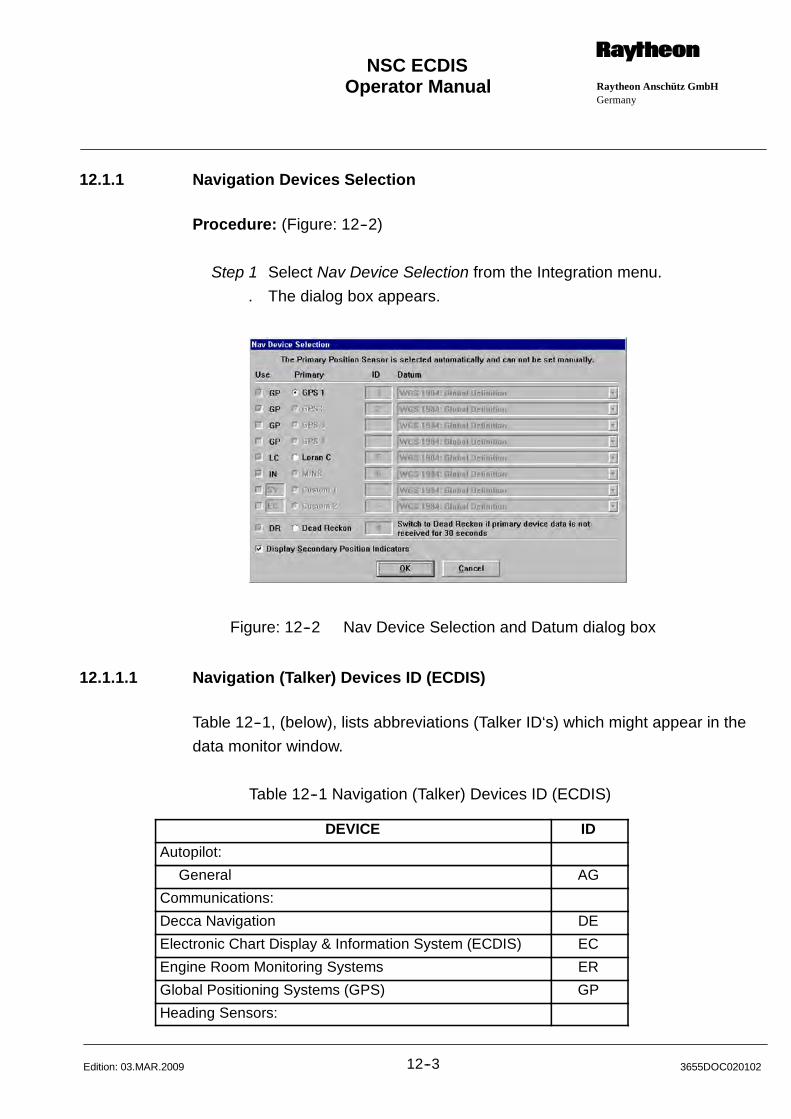
Operator Manual Raytheon Anschütz GmbHGermany
RNSC ECDIS
12--3 3655DOC020102Edition: 03.MAR.2009
12.1.1 Navigation Devices Selection
Procedure: (Figure: 12--2)
Step 1 Select Nav Device Selection from the Integration menu.
. The dialog box appears.
Figure: 12--2 Nav Device Selection and Datum dialog box
12.1.1.1 Navigation (Talker) Devices ID (ECDIS)
Table 12--1, (below), lists abbreviations (Talker ID‘s) which might appear in the
data monitor window.
Table 12--1 Navigation (Talker) Devices ID (ECDIS)
DEVICE ID
Autopilot:
General AG
Communications:
Decca Navigation DE
Electronic Chart Display & Information System (ECDIS) EC
Engine Room Monitoring Systems ER
Global Positioning Systems (GPS) GP
Heading Sensors:

Operator Manual
12--43655DOC020102 Edition: 03.MAR.2009
DEVICE ID
Compass, Magnetic HC
Gyro, Non--North Seeking HN
Integrated Instrumentation II
Integrated Navigation IN
Loran:
Loran C LC
Proprietary Code P
Radar and/or ARPA RA
Sounder, Depth SD
Electronic Positioning System, other/general SN
Sounder, Scanning SS
Turn Rate Indicator TI
Transit Navigation System TR
Velocity Sensors:
Doppler, other/general VD
Speed Log, Water, Magnetic VM
Speed Log, Water, Mechanical VW
Timekeepers, Time/Date
Atomic Clock ZA
Chronometer ZC
Quartz ZQ
Radio Update, WWV or WWVH ZV
Weather Instruments WI
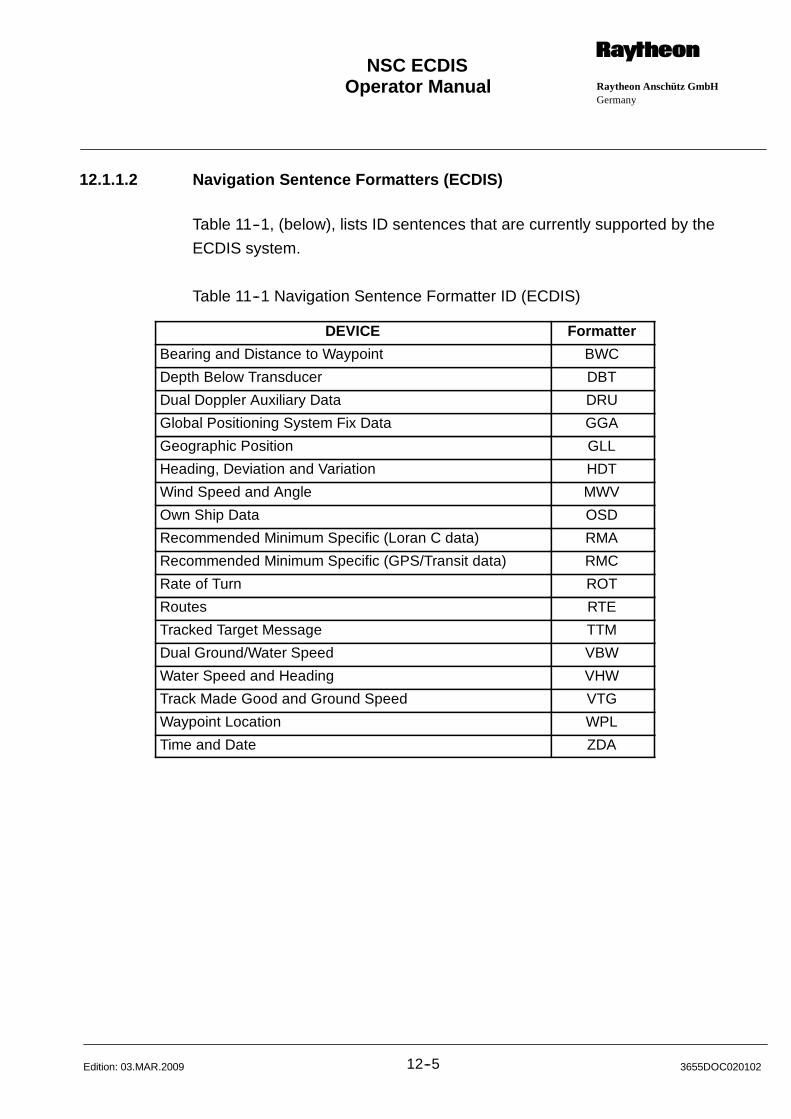
Operator Manual Raytheon Anschütz GmbHGermany
RNSC ECDIS
12--5 3655DOC020102Edition: 03.MAR.2009
12.1.1.2 Navigation Sentence Formatters (ECDIS)
Table 11--1, (below), lists ID sentences that are currently supported by the
ECDIS system.
Table 11--1 Navigation Sentence Formatter ID (ECDIS)
DEVICE Formatter
Bearing and Distance to Waypoint BWC
Depth Below Transducer DBT
Dual Doppler Auxiliary Data DRU
Global Positioning System Fix Data GGA
Geographic Position GLL
Heading, Deviation and Variation HDT
Wind Speed and Angle MWV
Own Ship Data OSD
Recommended Minimum Specific (Loran C data) RMA
Recommended Minimum Specific (GPS/Transit data) RMC
Rate of Turn ROT
Routes RTE
Tracked Target Message TTM
Dual Ground/Water Speed VBW
Water Speed and Heading VHW
Track Made Good and Ground Speed VTG
Waypoint Location WPL
Time and Date ZDA
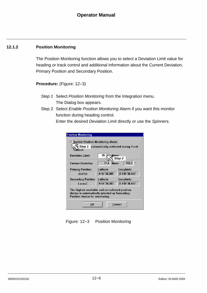
Operator Manual
12--63655DOC020102 Edition: 03.MAR.2009
12.1.2 Position Monitoring
The Position Monitoring function allows you to select a Deviation Limit value for
heading or track control and additional information about the Current Deviation,
Primary Position and Secondary Position.
Procedure: (Figure: 12--3)
Step 1 Select Position Monitoring from the Integration menu.
The Dialog box appears.
Step 2 Select Enable Position Monitoring Alarm if you want this monitor
function during heading control.
Enter the desired Deviation Limit directly or use the Spinners.
Step 1
Step 2
Figure: 12--3 Position Monitoring
Operator Manual Raytheon Anschütz GmbHGermany
RNSC ECDIS
12--7 3655DOC020102Edition: 15.JAN.2013
12.1.3 AIS Options
The Automatic Identification System (AIS) is designed for automatic and autono-
mous data communication between ships. The communication data consists of
information such as identification, position, speed, course over ground (detailed
information see AIS Manual).
The ECDIS is able to exchange text messages with other ships via AIS.
12.1.3.1 Calling up AIS Options
If there is an AIS connected to the ECDIS, AIS targets can be displayed on the
ECDIS screen, detailed information on AIS Targets can be shown on request
and Alarms for LOST and DANGEROUS AIS Targets will be generated.
The AIS Options... function allows to change the following settings
(Figure: 12--4):
Options
-- The Display of AIS Targets can be enabled or disabled.
-- Progressive ships movement.
-- Ship trails (available in progressive mode only).
-- Show Labels on active Targets.
-- Draw the Hull shape. If the AIS target symbol displays only, select the
Zoom In function until the symbol changed to the Hull shape.
-- Show AIS Aids to Navigation (AtoN) and Base Stations
-- All Targets (except for dangerous targets) can be displayed as Sleeping
Targets.
-- The Range at which the AIS Targets shall be displayed can be set from 10
to 55 NM.
-- A range can be defined, above which no LOST Target Alarms will be
generated.
All Targets which got lost outside this range will disappear immediately
without an indication.
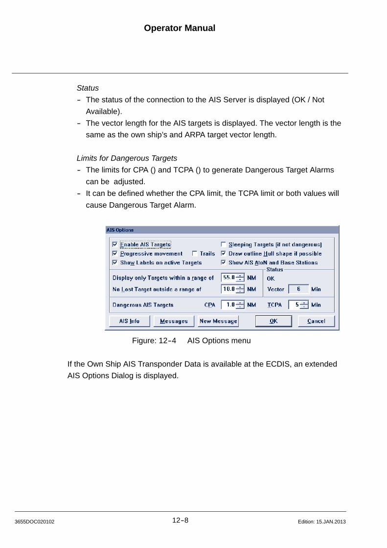
Operator Manual
12--83655DOC020102 Edition: 15.JAN.2013
Status
-- The status of the connection to the AIS Server is displayed (OK / Not
Available).
-- The vector length for the AIS targets is displayed. The vector length is the
same as the own ship’s and ARPA target vector length.
Limits for Dangerous Targets
-- The limits for CPA () and TCPA () to generate Dangerous Target Alarms
can be adjusted.
-- It can be defined whether the CPA limit, the TCPA limit or both values will
cause Dangerous Target Alarm.
Figure: 12--4 AIS Options menu
If the Own Ship AIS Transponder Data is available at the ECDIS, an extended
AIS Options Dialog is displayed.
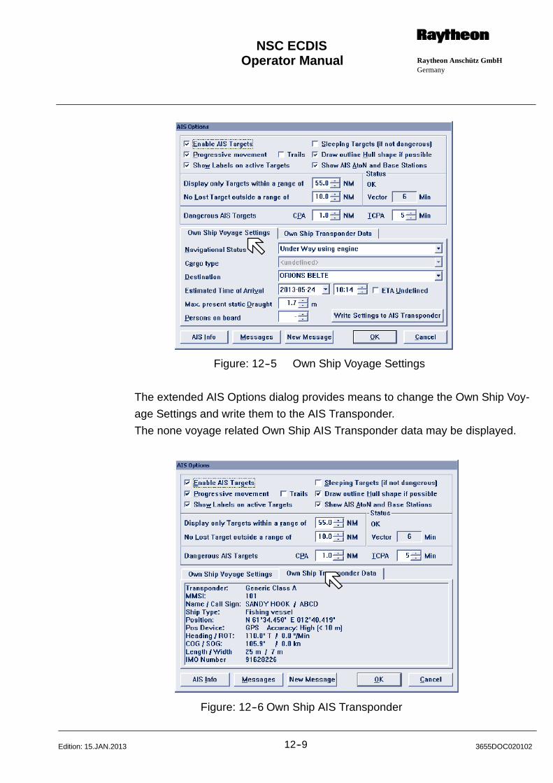
Operator Manual Raytheon Anschütz GmbHGermany
RNSC ECDIS
12--9 3655DOC020102Edition: 15.JAN.2013
Figure: 12--5 Own Ship Voyage Settings
The extended AIS Options dialog provides means to change the Own Ship Voy-
age Settings and write them to the AIS Transponder.
The none voyage related Own Ship AIS Transponder data may be displayed.
Figure: 12--6 Own Ship AIS Transponder
Operator Manual
12--103655DOC020102 Edition: 15.JAN.2013
Procedure: (Figure: 12--7)
Step 1 Select Target Options.. from the Integration menu or alternative via Tool
Bar Key.
The Dialog box appears.
Select and change the Options... and Limits for Dangerous Targets.
Step 2 Click on the OK button. The target presentation changes, the dialog
box is closed.
Or click on the Cancel button, all changes are discarded.
The dialog box is closed.
Step 3 Click on the Target Information button, the Target Information window
appears.
This dialog can also be accessed by cursor, [Middle] clicking
trackball button on an AIS Target.
For changing the selected Target, place the cursor at a User ID and
click on the [Left] button. Or place the cursor on an Target in
the chart and click on the middle button.
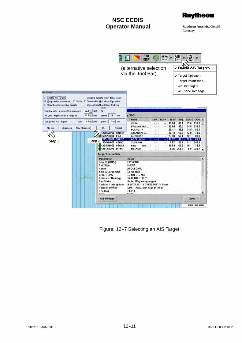
Operator Manual Raytheon Anschütz GmbHGermany
RNSC ECDIS
12--11 3655DOC020102Edition: 15.JAN.2013
(alternative selectionvia the Tool Bar)
Step 2Step 3
Figure: 12--7 Selecting an AIS Target
Operator Manual
12--123655DOC020102 Edition: 03.MAR.2009
12.1.3.2 AIS Messages
The ECDIS is able to exchange text messages with other ships via AIS.
Procedure: (Figure: 12--8)
Step 1 Select AIS Options.. from the Integration menu.
The Dialog box appears.
Step 2 Click on the Messages button.
The AIS Messages box appears and shows a list of previously sent and
received AIS messages.
Step 3 There are options to filter the AIS messages;
Direction can be ANY or SEND or RECEIVED
Type can be ANY or SAFETY or BINARY
Addressed can be ANY or BROADCAST or ADDRESSED
Step 4 Click on the New Message button
NOTE
The reception of a new AIS message will be indicated by a warning in
the ECDIS Alarm window.
The New Message box appears.
The message may be send as Binary Text Message or as a Safety
Related Message to either a dedicated AIS Target or as Broadcast
Message.
The arrow button on the right provides some standard distress
messages which messages which may be inserted into the message
text.
Edit your text file and press the Send button.
Step 5 Click on the Clear List button.
All AIS entries (depending from the Filter attributes) will be deleted.
Step 6 Click on the Delete Sel button.
The selected AIS message will be deleted.
Step 7 Click on the Export button.
The selected AIS message will be stored on a removal USB device.
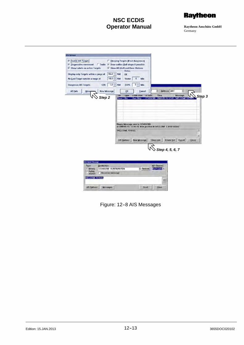
Operator Manual Raytheon Anschütz GmbHGermany
RNSC ECDIS
12--13 3655DOC020102Edition: 15.JAN.2013
Step 3
Step 4, 5, 6, 7
Step 2
Figure: 12--8 AIS Messages
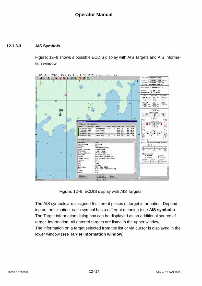
Operator Manual
12--143655DOC020102 Edition: 15.JAN.2013
12.1.3.3 AIS Symbols
Figure: 12--9 shows a possible ECDIS display with AIS Targets and AIS Informa-
tion window.
Figure: 12--9 ECDIS display with AIS Targets
The AIS symbols are assigned 5 different pieces of target information. Depend-
ing on the situation, each symbol has a different meaning (see AIS symbols).
The Target information dialog box can be displayed as an additional source of
target information. All entered targets are listed in the upper window.
The information on a target selected from the list or via cursor is displayed in the
lower window (see Target Information window).
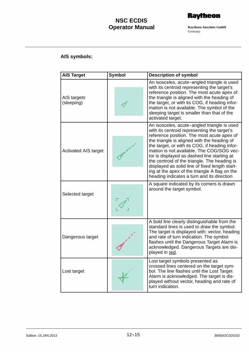
Operator Manual Raytheon Anschütz GmbHGermany
RNSC ECDIS
12--15 3655DOC020102Edition: 15.JAN.2013
AIS symbols:
AIS Target Symbol Description of symbol
AIS targets(sleeping)
An isosceles, acute--angled triangle is usedwith its centroid representing the target’sreference position. The most acute apex ofthe triangle is aligned with the heading ofthe target, or with its COG, if heading infor-mation is not available. The symbol of thesleeping target is smaller than that of theactivated target.
Activated AIS target
An isosceles, acute--angled triangle is usedwith its centroid representing the target’sreference position. The most acute apex ofthe triangle is aligned with the heading ofthe target, or with its COG, if heading infor-mation is not available. The COG/SOG vec-tor is displayed as dashed line starting atthe centroid of the triangle. The heading isdisplayed as solid line of fixed length start-ing at the apex of the triangle A flag on theheading indicates a turn and its direction
Selected target
A square indicated by its corners is drawnaround the target symbol.
Dangerous target
A bold line clearly distinguishable from thestandard lines is used to draw the symbol.The target is displayed with: vector, headingand rate of turn indication. The symbolflashes until the Dangerous Target Alarm isacknowledged. Dangerous Targets are dis-played in red.
Lost target
Lost target symbols presented ascrossed lines centered on the target sym-bol. The line flashes until the Lost TargetAlarm is acknowledged. The target is dis-played without vector, heading and rate ofturn indication.
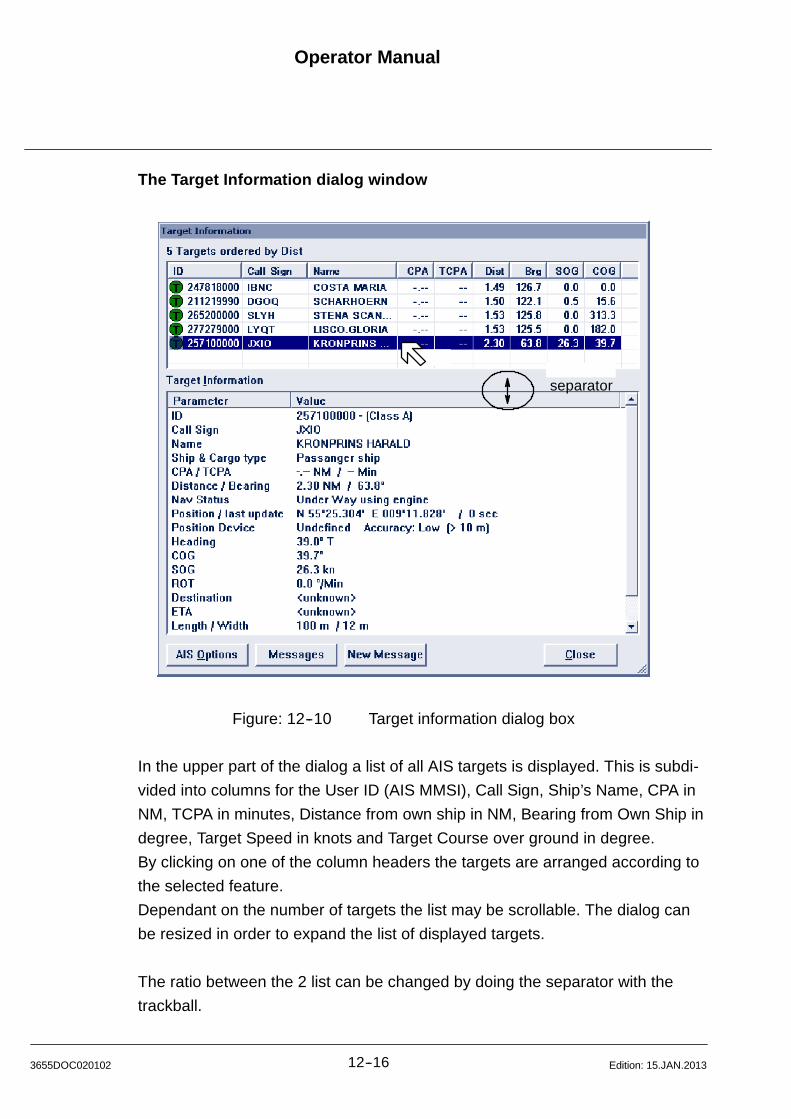
Operator Manual
12--163655DOC020102 Edition: 15.JAN.2013
The Target Information dialog window
separator
Figure: 12--10 Target information dialog box
In the upper part of the dialog a list of all AIS targets is displayed. This is subdi-
vided into columns for the User ID (AIS MMSI), Call Sign, Ship’s Name, CPA in
NM, TCPA in minutes, Distance from own ship in NM, Bearing from Own Ship in
degree, Target Speed in knots and Target Course over ground in degree.
By clicking on one of the column headers the targets are arranged according to
the selected feature.
Dependant on the number of targets the list may be scrollable. The dialog can
be resized in order to expand the list of displayed targets.
The ratio between the 2 list can be changed by doing the separator with the
trackball.
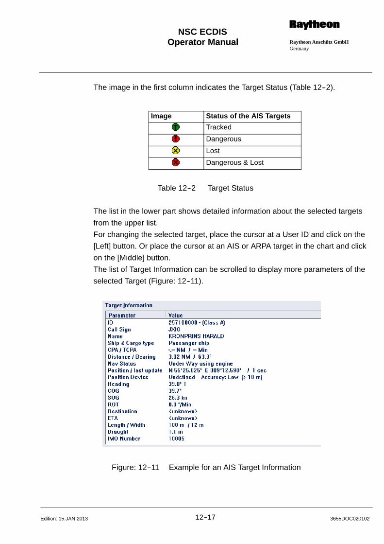
Operator Manual Raytheon Anschütz GmbHGermany
RNSC ECDIS
12--17 3655DOC020102Edition: 15.JAN.2013
The image in the first column indicates the Target Status (Table 12--2).
Image Status of the AIS Targets
Tracked
Dangerous
Lost
Dangerous & Lost
Table 12--2 Target Status
The list in the lower part shows detailed information about the selected targets
from the upper list.
For changing the selected target, place the cursor at a User ID and click on the
[Left] button. Or place the cursor at an AIS or ARPA target in the chart and click
on the [Middle] button.
The list of Target Information can be scrolled to display more parameters of the
selected Target (Figure: 12--11).
Figure: 12--11 Example for an AIS Target Information

Operator Manual
12--183655DOC020102 Edition: 15.JAN.2013
If the selected Target is Dangerous, this is also indicated in the CPA/TCPA row
(DANGEROUS TARGET).
If the selected Target is Lost, this is also indicated in the Position row (LOST
TARGET).
All target information which is (currently) not available is indicated as <un-
known>.
The contents of both lists is updated in regular intervals.
The button AIS Options will open the AIS Options dialog (chapter 12.1.3.1).
Operator Manual Raytheon Anschütz GmbHGermany
RNSC ECDIS
12--19 3655DOC020102Edition: 15.JAN.2013
12.1.4 Integrating an ARPA Radar
NOTE
When integrating a radar which will accept data from ECDIS, it must
not share a COM port with any other navigation device.
ECDIS’s ARPA radar interface allows you to integrate up to 6 radars as well as
display and track up to 1000 acquired targets with optional target tracks, target
trails and heading vectors per radar. The targets appear on the display as green
colored symbols.
The target trails are like a high resolution ship’s track. They contain only a limited
number of points. Once a trail is ”full,” ECDIS begins dropping points off one end
of the trail while adding them to the other. Target trails are displayed in real time
only that is, they cannot be saved and redisplay. To turn them off, simply se-
lect the Off button in the ARPA Radar Tracking dialog box.
ARPA target heading vectors are the same length as your own ship vector.
ECDIS is capable of sending marker, lines and route information to selected ra-
dars. When sending information to be displayed on this radar, it must be the ra-
dar selected to be used in the ARPA Radar Tracking dialog box.
If ECDIS does not receive a signal from the target, the target is cleared from the
display. Please see ”Selecting the Navigation Devices”, chapter 7.1.2.
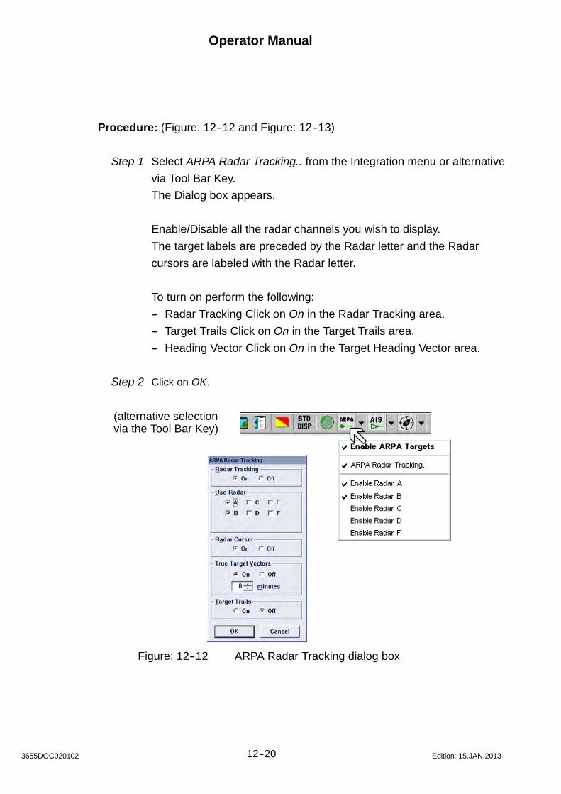
Operator Manual
12--203655DOC020102 Edition: 15.JAN.2013
Procedure: (Figure: 12--12 and Figure: 12--13)
Step 1 Select ARPA Radar Tracking.. from the Integration menu or alternative
via Tool Bar Key.
The Dialog box appears.
Enable/Disable all the radar channels you wish to display.
The target labels are preceded by the Radar letter and the Radar
cursors are labeled with the Radar letter.
To turn on perform the following:
-- Radar Tracking Click on On in the Radar Tracking area.
-- Target Trails Click on On in the Target Trails area.
-- Heading Vector Click on On in the Target Heading Vector area.
Step 2 Click on OK.
(alternative selectionvia the Tool Bar Key)
Figure: 12--12 ARPA Radar Tracking dialog box
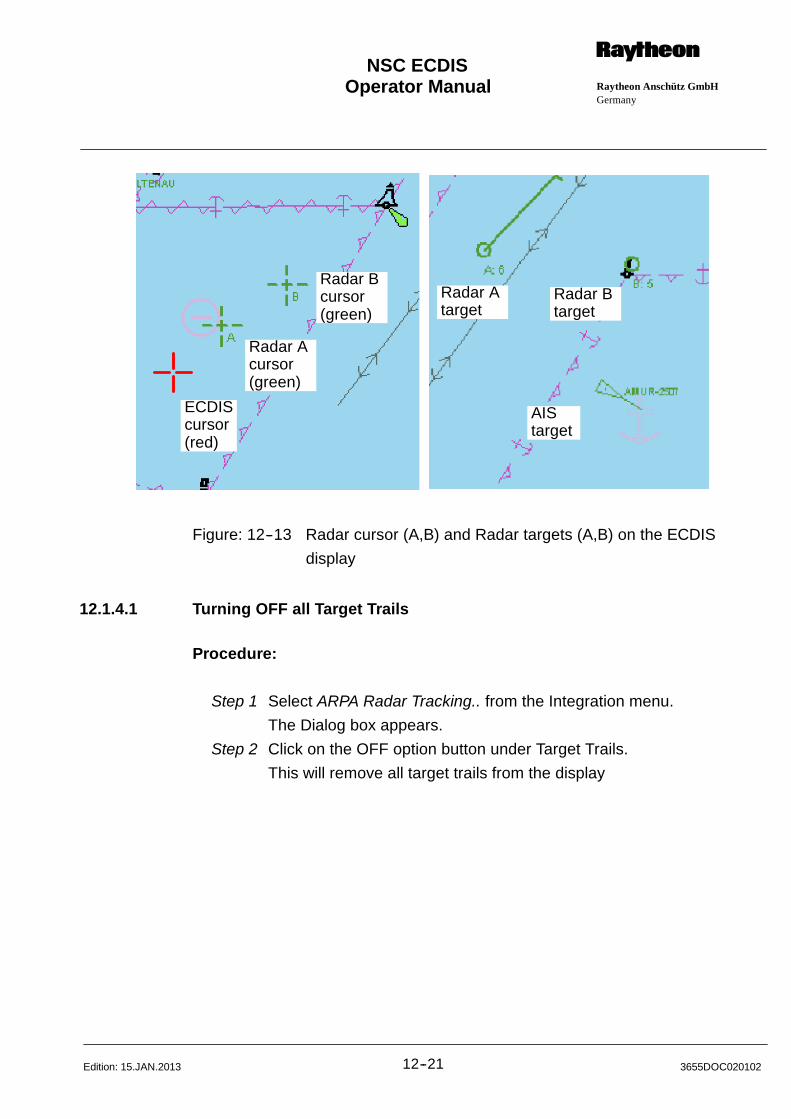
Operator Manual Raytheon Anschütz GmbHGermany
RNSC ECDIS
12--21 3655DOC020102Edition: 15.JAN.2013
ECDIScursor(red)
Radar Acursor(green)
Radar Bcursor(green)
Radar Btarget
Radar Atarget
AIStarget
Figure: 12--13 Radar cursor (A,B) and Radar targets (A,B) on the ECDIS
display
12.1.4.1 Turning OFF all Target Trails
Procedure:
Step 1 Select ARPA Radar Tracking.. from the Integration menu.
The Dialog box appears.
Step 2 Click on the OFF option button under Target Trails.
This will remove all target trails from the display
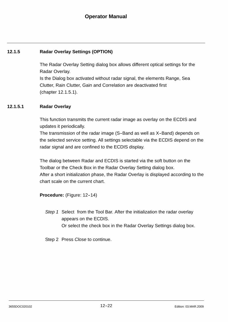
Operator Manual
12--223655DOC020102 Edition: 03.MAR.2009
12.1.5 Radar Overlay Settings (OPTION)
The Radar Overlay Setting dialog box allows different optical settings for the
Radar Overlay.
Is the Dialog box activated without radar signal, the elements Range, Sea
Clutter, Rain Clutter, Gain and Correlation are deactivated first
(chapter 12.1.5.1).
12.1.5.1 Radar Overlay
This function transmits the current radar image as overlay on the ECDIS and
updates it periodically.
The transmission of the radar image (S--Band as well as X--Band) depends on
the selected service setting. All settings selectable via the ECDIS depend on the
radar signal and are confined to the ECDIS display.
The dialog between Radar and ECDIS is started via the soft button on the
Toolbar or the Check Box in the Radar Overlay Setting dialog box.
After a short initialization phase, the Radar Overlay is displayed according to the
chart scale on the current chart.
Procedure: (Figure: 12--14)
Step 1 Select from the Tool Bar. After the initialization the radar overlay
appears on the ECDIS.
Or select the check box in the Radar Overlay Settings dialog box.
Step 2 Press Close to continue.
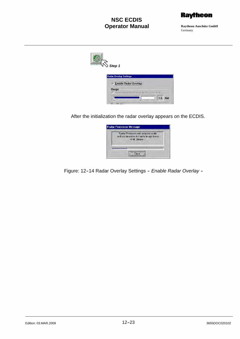
Operator Manual Raytheon Anschütz GmbHGermany
RNSC ECDIS
12--23 3655DOC020102Edition: 03.MAR.2009
After the initialization the radar overlay appears on the ECDIS.
Step 1
Figure: 12--14 Radar Overlay Settings -- Enable Radar Overlay --
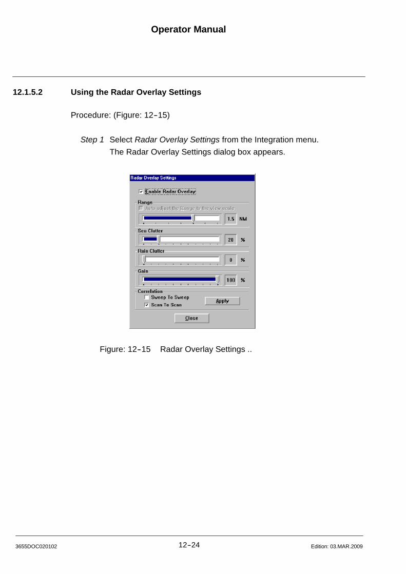
Operator Manual
12--243655DOC020102 Edition: 03.MAR.2009
12.1.5.2 Using the Radar Overlay Settings
Procedure: (Figure: 12--15)
Step 1 Select Radar Overlay Settings from the Integration menu.
The Radar Overlay Settings dialog box appears.
Figure: 12--15 Radar Overlay Settings ..
Operator Manual Raytheon Anschütz GmbHGermany
RNSC ECDIS
12--25 3655DOC020102Edition: 03.MAR.2009
Slider Range
The Range area on the ECDIS depends on the Pulse Width/Range selection
on the RADAR (Figure: 12--16).
RADARPulse Width Selection
SHORT
MED1
MED2
LONG
ECDISRange Selection
0,1250,250,50,751,5
3,06,012,0
24,048,0
Figure: 12--16 Pulse Width / Range Selection
If the Pulse Width/Range is changed on the RADAR, the range of the Radar
Overlay is automatically adjusted to the new range (Figure: 12--17).
starts with 1,5
starts with 3,0starts with 6,0 comming from MED1starts with 12,0 comming from LONG
starts with 24,0
RADARPulse Width Selection
SHORT
MED1
MED2
LONG
ECDISRange Selection
Figure: 12--17 Switch over to another Pulse Width
After the initialization the radar overlay appears on the ECDIS.
Operator Manual
12--263655DOC020102 Edition: 03.MAR.2009
Step 2 Use the check box Auto adjust the Range to the view scaleto centre
the Radar Overlay in ECDIS.
Slider Sea ClutterKeep adjusting Slider, as possible, until Sea Clutter is no longer disturbing
the Radar Overlay.
During this adjustment, the radar targets must be clearly visible at any time.
Slider Rain Clutter
Keep adjusting Slider, as possible, until Rain Clutter is no longer disturbing
the Radar Overlay.
During this adjustment, the radar targets must be clearly visible at any time.
Slider Gain
The Gain slider adjusts the sensitivty of the radar display. If properly
adjusted, the Gain control results in noise appearing as a light speckle
at the dim level.
This light speckle setting yields the maximum detectability of targets
against a noise backround. If the Gain is set too low, weak or distance tar
gets could be missed.
Correlation
Scan To Scan
This process requires 3 complete antenna rotations or scans of the
antenna to build up or decay detected targets.
To the operator, this means that when a target is first detected, it is painted
dim.
If on the next scan it is still present at the same location, it is painted at mid
level and on the third scan, it is painted bright. As long as the target is
present, is will paint bright. If the target fades in and out , then it will remain
on the screen, dropping from bright to mid and back to bright. If the target
is lost altogether, then it will take three scans before it completely
disappears.
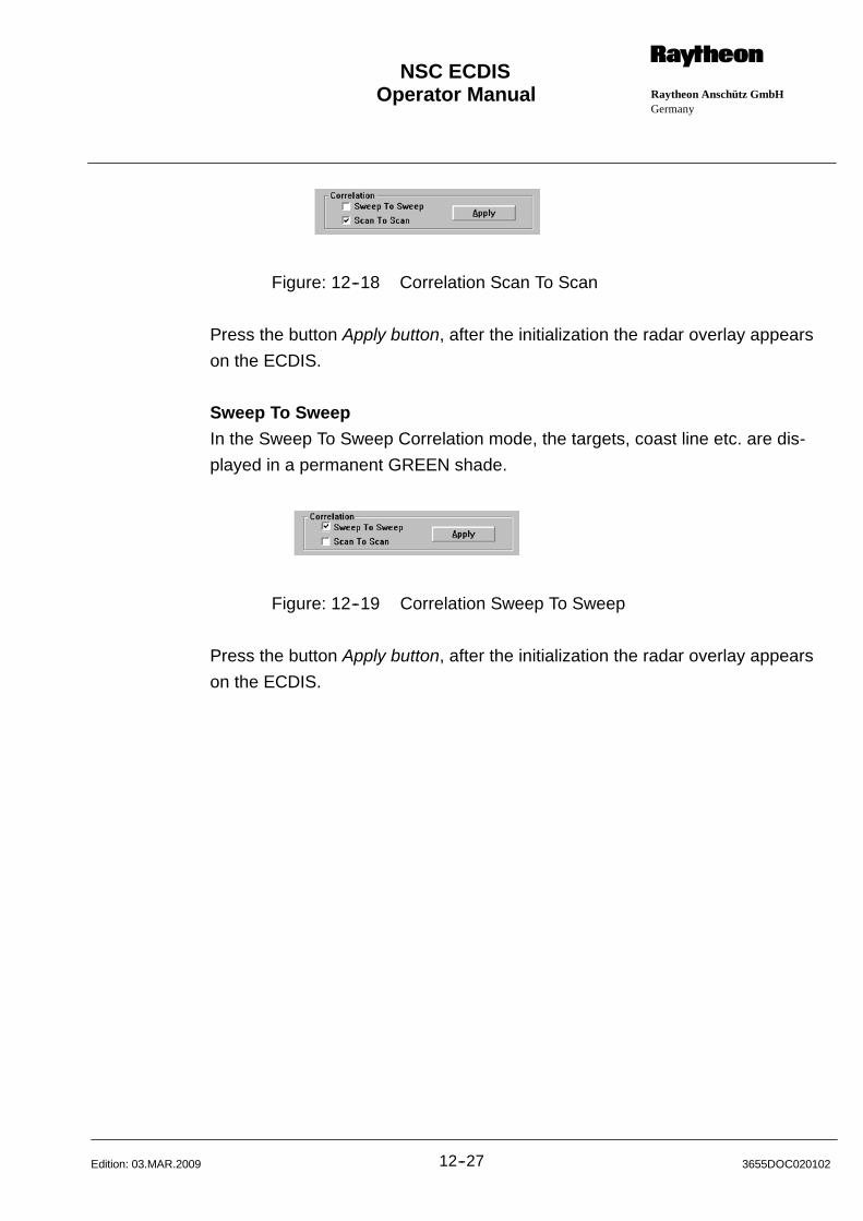
Operator Manual Raytheon Anschütz GmbHGermany
RNSC ECDIS
12--27 3655DOC020102Edition: 03.MAR.2009
Figure: 12--18 Correlation Scan To Scan
Press the button Apply button, after the initialization the radar overlay appears
on the ECDIS.
Sweep To Sweep
In the Sweep To Sweep Correlation mode, the targets, coast line etc. are dis-
played in a permanent GREEN shade.
Figure: 12--19 Correlation Sweep To Sweep
Press the button Apply button, after the initialization the radar overlay appears
on the ECDIS.
Operator Manual
12--283655DOC020102 Edition: 03.MAR.2009
12.1.6 Driving an Autopilot
NOTE
Track Control is not an ECDIS function. To activate this function an
AUTOPILOT System has to be connected. For detailed information ask
Raytheon Anschütz.
ECDIS allows the user to turn on or off the transmission of data to the autopilot
as well as to specify a rate of turn, and the turning response. The turning re-
sponse is the distance (number of ship lengths) you wish the autopilot to start
turning the ship prior to reaching the wheel overpoint position. The ”WOP”
(wheel over point) marker will be moved to that location.
If you have an open route with an active waypoint, and you change the rate of
turn, you will also change the predicted turning arc. Please see ”Edit Route
Command”, chapter 8.2.1.
When integrating an autopilot, it is necessary to connect it to an un--shared port.
This is because autopilot data transmission is turned on and off using the Autopi-
lot command. If the autopilot shares a port with another device, the data trans-
mission of the device which shares the same port will also be stopped.
NOTE
The Talker ID, NMEA Output, and Checksum values should be entered
when first integrating the autopilot. They do not need to be changed
unless a new autopilot is integrated. For a complete list of ECDIS talker
IDs please see Table 12--1 .
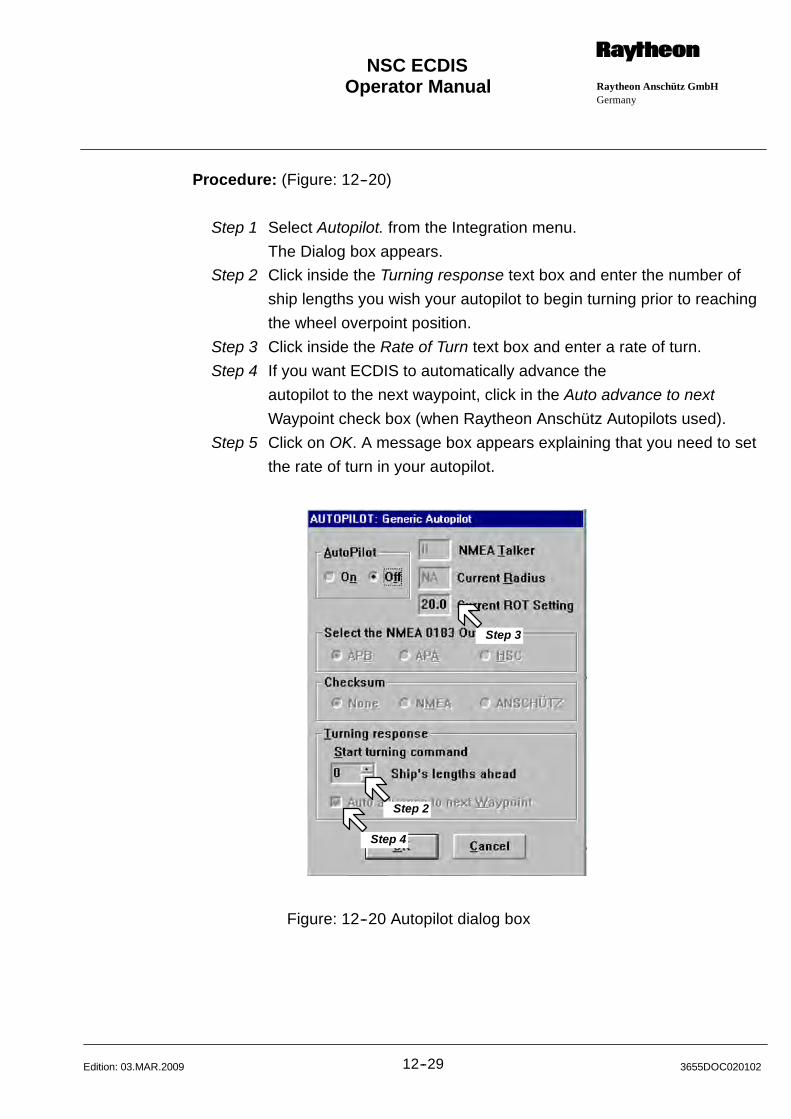
Operator Manual Raytheon Anschütz GmbHGermany
RNSC ECDIS
12--29 3655DOC020102Edition: 03.MAR.2009
Procedure: (Figure: 12--20)
Step 1 Select Autopilot. from the Integration menu.
The Dialog box appears.
Step 2 Click inside the Turning response text box and enter the number of
ship lengths you wish your autopilot to begin turning prior to reaching
the wheel overpoint position.
Step 3 Click inside the Rate of Turn text box and enter a rate of turn.
Step 4 If you want ECDIS to automatically advance the
autopilot to the next waypoint, click in the Auto advance to next
Waypoint check box (when Raytheon Anschütz Autopilots used).
Step 5 Click on OK. A message box appears explaining that you need to set
the rate of turn in your autopilot.
Step 2
Step 3
Step 4
Figure: 12--20 Autopilot dialog box
Operator Manual
12--303655DOC020102 Edition: 26.JUL.2010
12.1.7 Integrating a Depth Sounder/ Setting the Depth Alarm
Use the Echosounder command to set an alarm depth. If you want to change the
unit of measure for the depth display and alarm.
If the Conning Display Monitor (Option) is connected to the ECDIS the scaling of
the depth display will be changed at the same time.
WARNING
ALARM DEPTH MUST BE CALCULATED FROM THE TRANSDUCER
HEAD, NOT FROM THE KEEL OR THE SURFACE.
The Depth Alarm is only active if you have a depth sounder integrated with
ECDIS. You may use depth alarm to alert you when the depth beneath the ship
is equal to or shallower than a depth you specify.
When the alarm is triggered, ECDIS displays a warning message and beeps
every 5 seconds.
Procedure: (Figure: 12--21)
Step 1 Select Echosounder. from the Integration menu.
The Dialog box appears.
Step 2 Click in the Alarm Depth text box, then type the depth at which you
want the depth alarm to go off or select Auto.
Notice that the units for the alarm appear to the right of the box.
Step 3 Click on OK. When the depth beneath your ship’s transducer is equal
to or shallower than the specified alarm depth, ECDIS displays a
warning message and sounds an alarm.
Step 4 To turn off the alarm, click on Acknowledge.
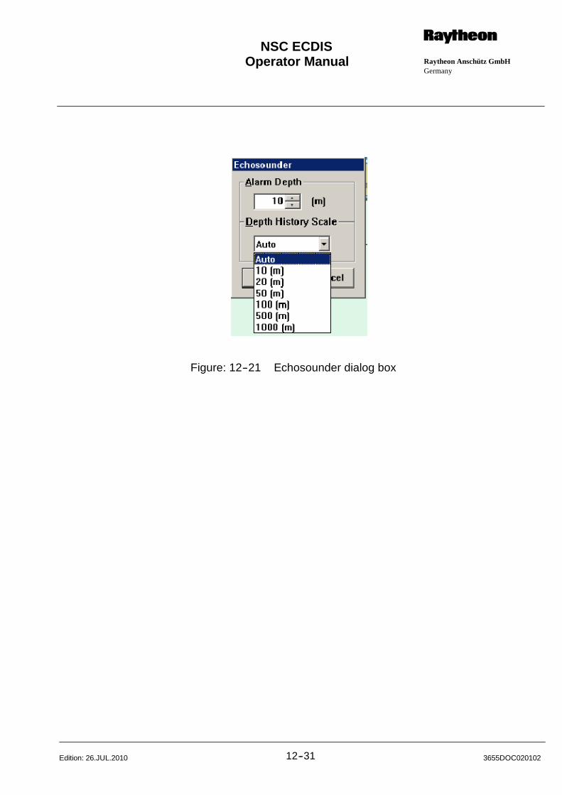
Operator Manual Raytheon Anschütz GmbHGermany
RNSC ECDIS
12--31 3655DOC020102Edition: 26.JUL.2010
Figure: 12--21 Echosounder dialog box
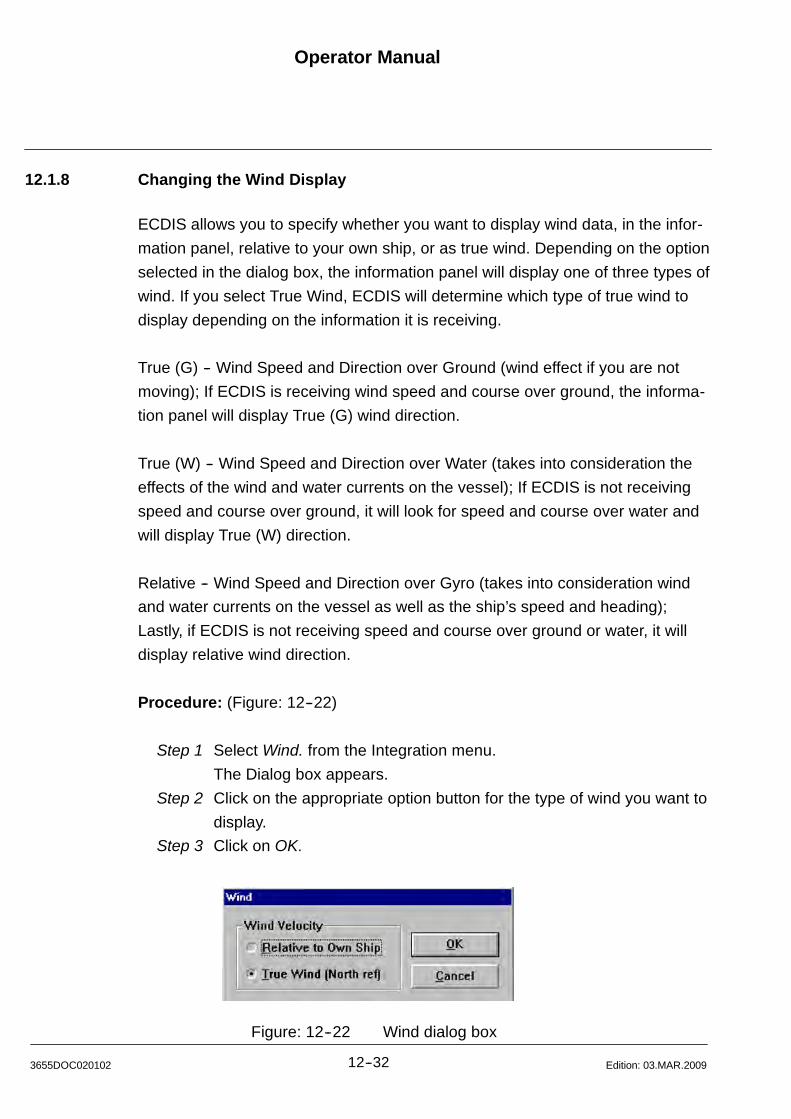
Operator Manual
12--323655DOC020102 Edition: 03.MAR.2009
12.1.8 Changing the Wind Display
ECDIS allows you to specify whether you want to display wind data, in the infor-
mation panel, relative to your own ship, or as true wind. Depending on the option
selected in the dialog box, the information panel will display one of three types of
wind. If you select True Wind, ECDIS will determine which type of true wind to
display depending on the information it is receiving.
True (G) -- Wind Speed and Direction over Ground (wind effect if you are not
moving); If ECDIS is receiving wind speed and course over ground, the informa-
tion panel will display True (G) wind direction.
True (W) -- Wind Speed and Direction over Water (takes into consideration the
effects of the wind and water currents on the vessel); If ECDIS is not receiving
speed and course over ground, it will look for speed and course over water and
will display True (W) direction.
Relative -- Wind Speed and Direction over Gyro (takes into consideration wind
and water currents on the vessel as well as the ship’s speed and heading);
Lastly, if ECDIS is not receiving speed and course over ground or water, it will
display relative wind direction.
Procedure: (Figure: 12--22)
Step 1 Select Wind. from the Integration menu.
The Dialog box appears.
Step 2 Click on the appropriate option button for the type of wind you want to
display.
Step 3 Click on OK.
Figure: 12--22 Wind dialog box
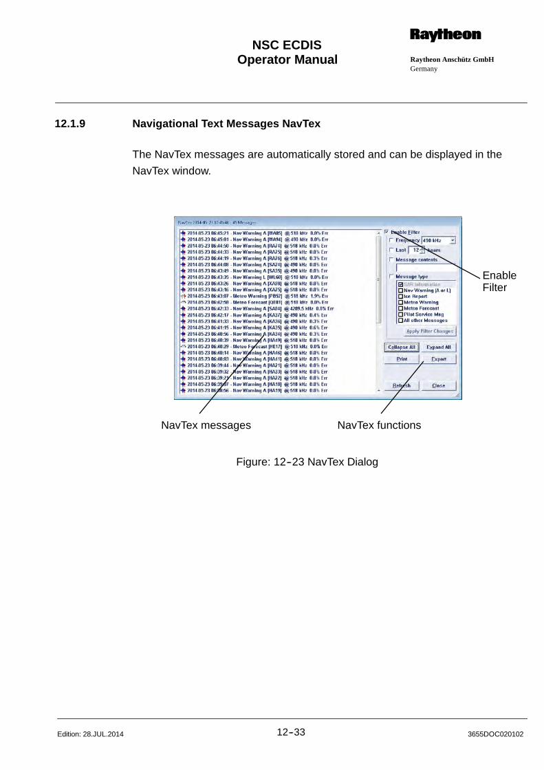
Operator Manual Raytheon Anschütz GmbHGermany
RNSC ECDIS
12--33 3655DOC020102Edition: 28.JUL.2014
12.1.9 Navigational Text Messages NavTex
The NavTex messages are automatically stored and can be displayed in the
NavTex window.
NavTex messages NavTex functions
EnableFilter
Figure: 12--23 NavTex Dialog
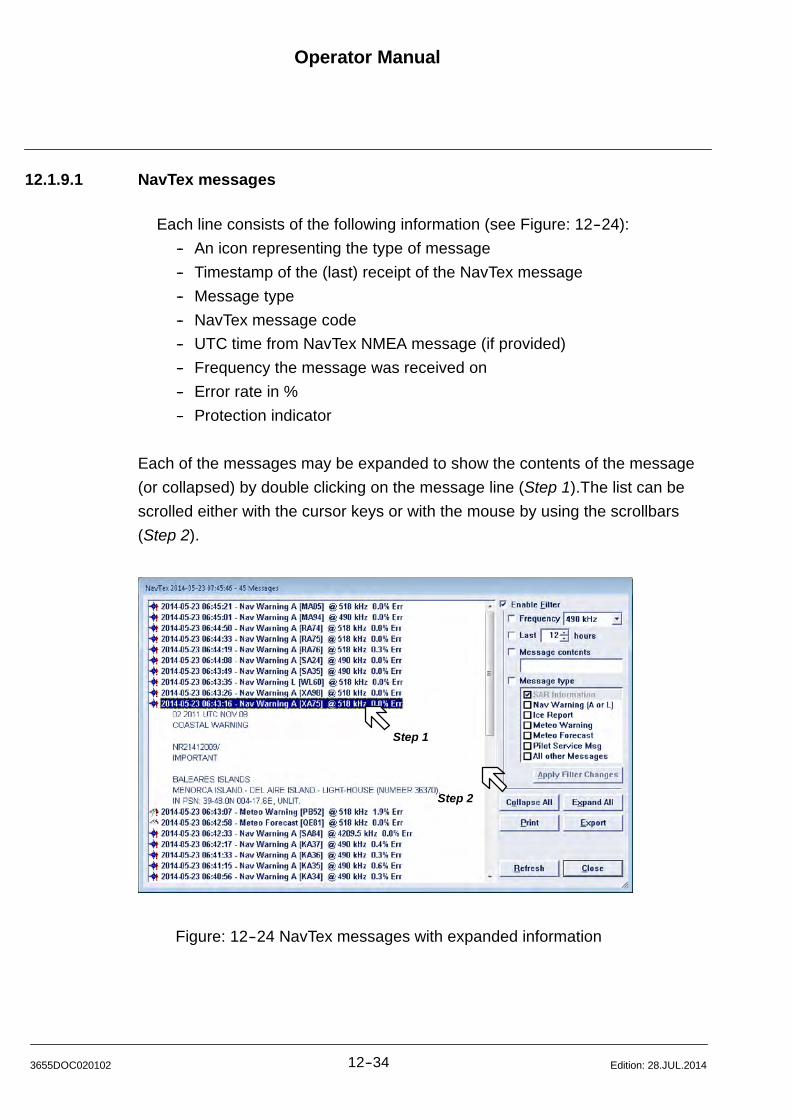
Operator Manual
12--343655DOC020102 Edition: 28.JUL.2014
12.1.9.1 NavTex messages
Each line consists of the following information (see Figure: 12--24):
-- An icon representing the type of message
-- Timestamp of the (last) receipt of the NavTex message
-- Message type
-- NavTex message code
-- UTC time from NavTex NMEA message (if provided)
-- Frequency the message was received on
-- Error rate in %
-- Protection indicator
Each of the messages may be expanded to show the contents of the message
(or collapsed) by double clicking on the message line (Step 1).The list can be
scrolled either with the cursor keys or with the mouse by using the scrollbars
(Step 2).
Step 1
Step 2
Figure: 12--24 NavTex messages with expanded information
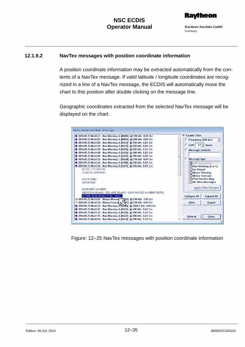
Operator Manual Raytheon Anschütz GmbHGermany
RNSC ECDIS
12--35 3655DOC020102Edition: 28.JUL.2014
12.1.9.2 NavTex messages with position coordinate information
A position coordinate information may be extracted automatically from the con-
tents of a NavTex message. If valid latitude / longitude coordinates are recog-
nized in a line of a NavTex message, the ECDIS will automatically move the
chart to this position after double clicking on the message line.
Geographic coordinates extracted from the selected NavTex message will be
displayed on the chart.
Figure: 12--25 NavTex messages with position coordinate information
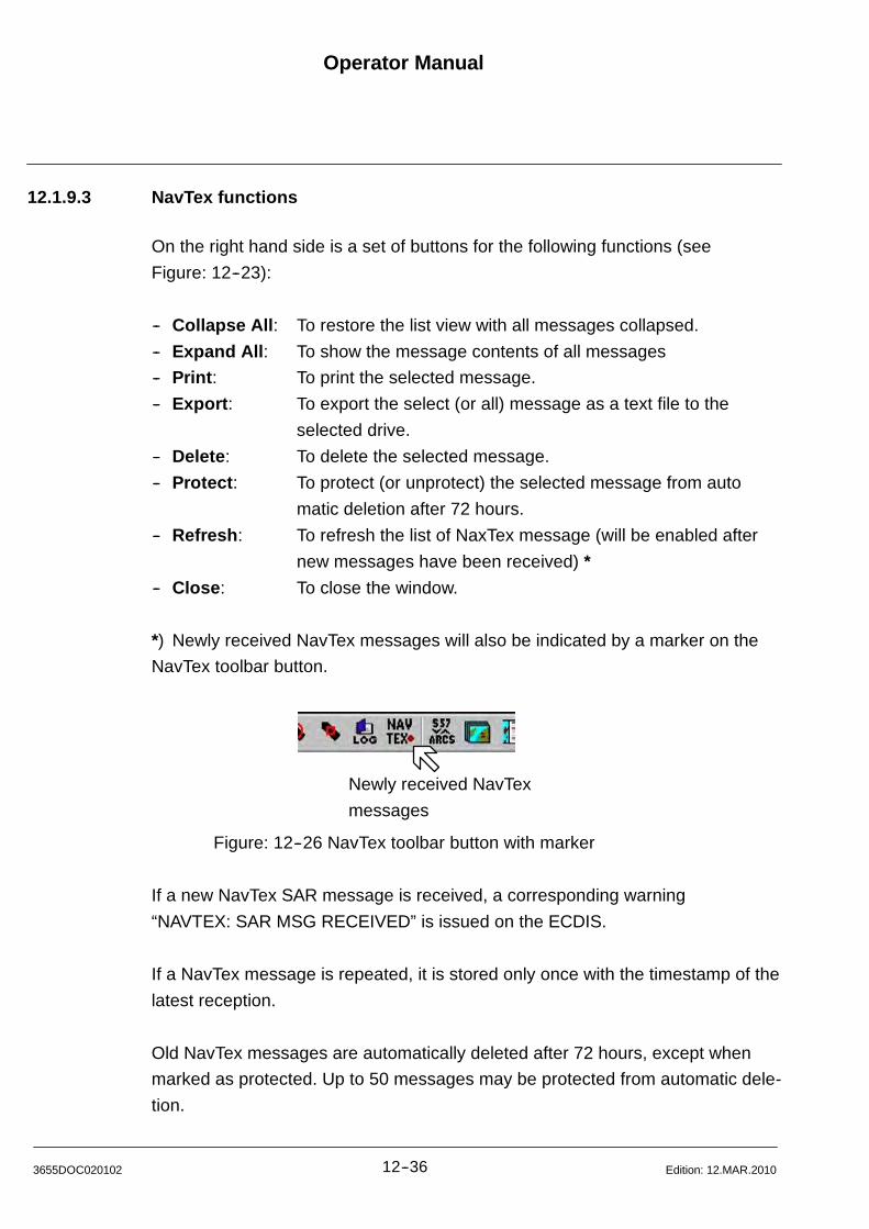
Operator Manual
12--363655DOC020102 Edition: 12.MAR.2010
12.1.9.3 NavTex functions
On the right hand side is a set of buttons for the following functions (see
Figure: 12--23):
-- Collapse All: To restore the list view with all messages collapsed.
-- Expand All: To show the message contents of all messages
-- Print: To print the selected message.
-- Export: To export the select (or all) message as a text file to the
selected drive.
-- Delete: To delete the selected message.
-- Protect: To protect (or unprotect) the selected message from auto
matic deletion after 72 hours.
-- Refresh: To refresh the list of NaxTex message (will be enabled after
new messages have been received) *
-- Close: To close the window.
*) Newly received NavTex messages will also be indicated by a marker on the
NavTex toolbar button.
Newly received NavTex
messages
Figure: 12--26 NavTex toolbar button with marker
If a new NavTex SAR message is received, a corresponding warning
“NAVTEX: SAR MSG RECEIVED” is issued on the ECDIS.
If a NavTex message is repeated, it is stored only once with the timestamp of the
latest reception.
Old NavTex messages are automatically deleted after 72 hours, except when
marked as protected. Up to 50 messages may be protected from automatic dele-
tion.

Operator Manual Raytheon Anschütz GmbHGermany
RNSC ECDIS
12--37 3655DOC020102Edition: 12.MAR.2010
12.1.9.4 Enable Filter
If the Enable Filter checkbox is marked, the list of NavTex message may be
filtered by the following criteria:
-- Frequency: The frequency on which the message has been received
(Not over air, 490 kHz, 518 kHz or 4209,5 kHz)
-- Last:: The age of the message (between 1 hour and 72 hours)
-- Messages content: The contents of the message text
-- Message type: The message type
Each time the filter criteria have been changed, the changes have to be applied
by the corresponding button. If the list of NavTex message is filtered, this is indi-
cated in the titlebar of the NaxTex window.
Figure: 12--27 NavTex messages with the Enable Filter function
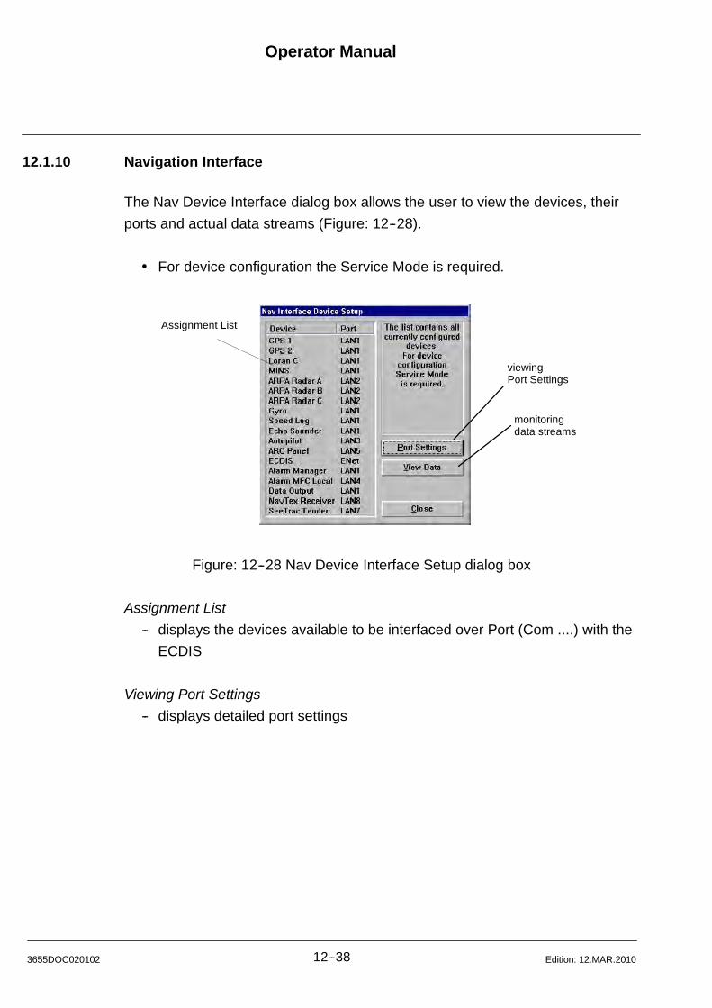
Operator Manual
12--383655DOC020102 Edition: 12.MAR.2010
12.1.10 Navigation Interface
The Nav Device Interface dialog box allows the user to view the devices, their
ports and actual data streams (Figure: 12--28).
For device configuration the Service Mode is required.
monitoringdata streams
Assignment List
viewingPort Settings
Figure: 12--28 Nav Device Interface Setup dialog box
Assignment List
-- displays the devices available to be interfaced over Port (Com ....) with the
ECDIS
Viewing Port Settings
-- displays detailed port settings
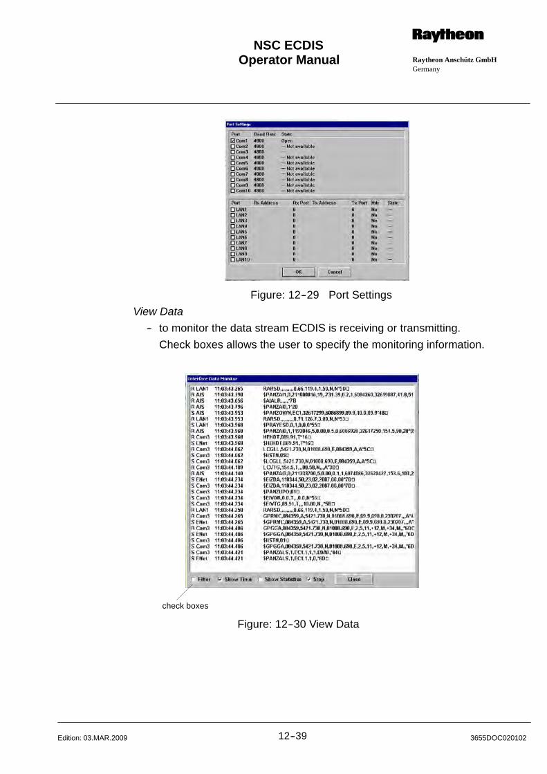
Operator Manual Raytheon Anschütz GmbHGermany
RNSC ECDIS
12--39 3655DOC020102Edition: 03.MAR.2009
Figure: 12--29 Port Settings
View Data
-- to monitor the data stream ECDIS is receiving or transmitting.
Check boxes allows the user to specify the monitoring information.
check boxes
Figure: 12--30 View Data
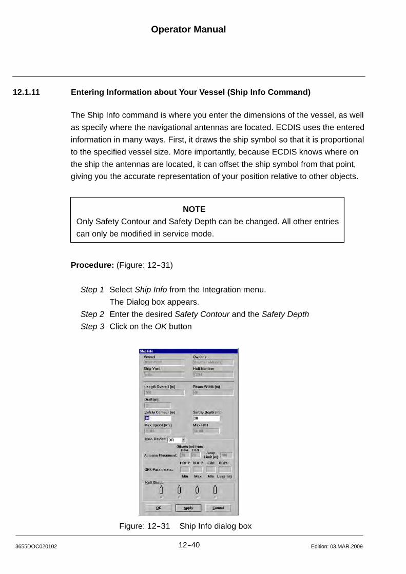
Operator Manual
12--403655DOC020102 Edition: 03.MAR.2009
12.1.11 Entering Information about Your Vessel (Ship Info Command)
The Ship Info command is where you enter the dimensions of the vessel, as well
as specify where the navigational antennas are located. ECDIS uses the entered
information in many ways. First, it draws the ship symbol so that it is proportional
to the specified vessel size. More importantly, because ECDIS knows where on
the ship the antennas are located, it can offset the ship symbol from that point,
giving you the accurate representation of your position relative to other objects.
NOTE
Only Safety Contour and Safety Depth can be changed. All other entries
can only be modified in service mode.
Procedure: (Figure: 12--31)
Step 1 Select Ship Info from the Integration menu.
The Dialog box appears.
Step 2 Enter the desired Safety Contour and the Safety Depth
Step 3 Click on the OK button
Figure: 12--31 Ship Info dialog box

Operator Manual Raytheon Anschütz GmbHGermany
RNSC ECDIS
12--41 3655DOC020102Edition: 03.MAR.2009
12.1.12 Tender Tracking (OPTION)
Tender Tracking implies a Seetrac Tender Tracking System.
The ECDIS on the main ship allows the Tender observation and recording.
The Tenders are displayed as small violet circles with a course vector.
Furthermore Tender information can be displayed via the Tender Information
window (Figure: 12--32).
Main Ship
Jet Ski
Tender B
Tender A
Tender Brecorded line withcolored depth in-formation
Figure: 12--32 ECDIS with Tender Tracking
Operator Manual
12--423655DOC020102 Edition: 22.NOV.2011
12.1.12.1 Tender Configuration (Option)
Note: Dependant on the Type of the Tender Tracking system there are minor
differences:
-- Some Tender Systems do not provide SOG and COG data for the Tenders. In
this case the Tender Symbols are displayed without a vector and SOG / COG
is not displayed in Tender Info.
-- The Tender ID may be called TTC or TID
-- Some Tender Systems do not require a Channel Number to be configured.
-- Some Tender Systems do not have a distinction between Managed Mode and
Autonomous Mode and do not need a TOC to be configured.
The Tender Configuration is subdivided into three configuration parts;
Options used to set general Tender Options
Configuration Tender used to maintain the configured Tenders
Manage Recordings used to manage recorded Tender trails
Procedure: Options (Figure: 12--33)
Step 1 Select Tender Configuration.. from the Integration menu or alternative
via Tool Bar Key..
The Dialog box appears.
Step 2 Enable the desired Tender Options such as
S Enable Display of Tenders and recorded trails
Show/Hide Tender symbols and recorded trails.
S Enable Lost Tender Alarm
Enable/Disable a TENDER LOST alarm if a Tender is no longer
reporting the position.
S Enable Tender Range Alarm
Enable/Disable a TENDER OUT OF RANGE alarm if the distance
to a Tender exceeds the set Range Limit.
S Manage Mode or Autonomous Mode
These Mode selection has to be done in dependency with the
Seetrac Basic Unit (done in the Service Mode).
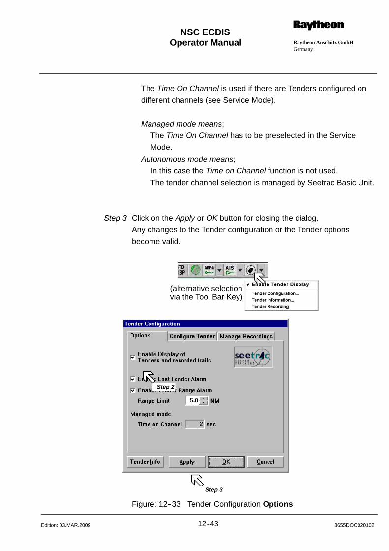
Operator Manual Raytheon Anschütz GmbHGermany
RNSC ECDIS
12--43 3655DOC020102Edition: 03.MAR.2009
The Time On Channel is used if there are Tenders configured on
different channels (see Service Mode).
Managed mode means;
The Time On Channel has to be preselected in the Service
Mode.
Autonomous mode means;
In this case the Time on Channel function is not used.
The tender channel selection is managed by Seetrac Basic Unit.
Step 3 Click on the Apply or OK button for closing the dialog.
Any changes to the Tender configuration or the Tender options
become valid.
(alternative selectionvia the Tool Bar Key)
Step 2
Step 3
Figure: 12--33 Tender Configuration Options
Operator Manual
12--443655DOC020102 Edition: 03.MAR.2009
Configure Tender is used to add new Tender, edit the values for TTC (Tender
Transmission Code), Name, Channel and Recording status.
Procedure: Configuration (Figure: 12--34)
Step 1 Select Tender Configuration.. from the Integration menu or as an
alternativly via the Tool Bar Key.
The Dialog box appears.
Step 2 Add a new Tender
TTC
TTC is the Tender ID which is set in the corresponding Tender unit.
A tender may be temporarily enabled or disabled by
checking/unchecking the checkbox.
Name
Each Tender may be assigned a name for display purposes.
Ch
The channel needs to be set to the corresponding coded channel
which is set in the corresponding Seetrac Tender unit.
Rec
Select when the tender shall be recorded using the Tender Recording
function.
Before changing the record status, Tender Recording has to be
disabled.
Step 3 A selected Tender may be Deleted, moved Up or Down in the List.
Step 4 Click on the Apply or OK button for closing the dialog.
Any changes to the Tender configuration or the Tender options
become valid.
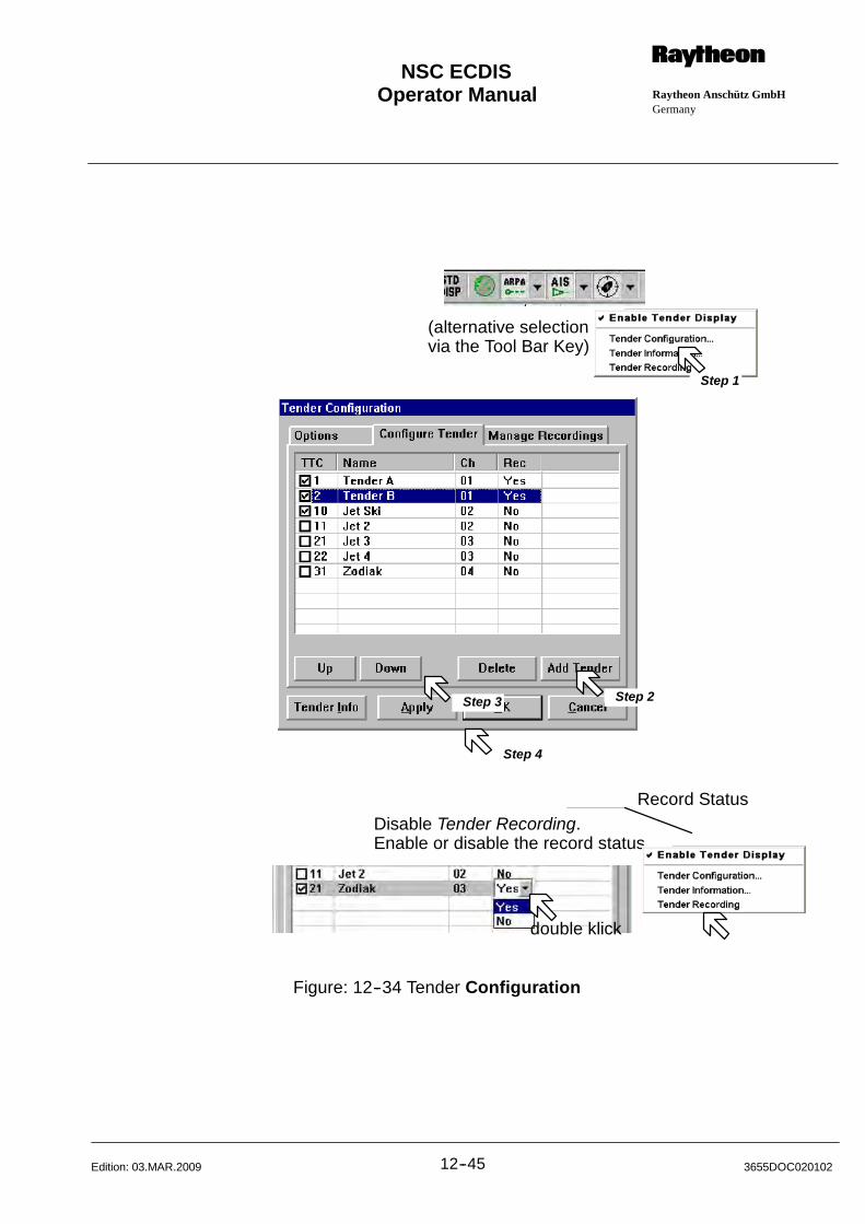
Operator Manual Raytheon Anschütz GmbHGermany
RNSC ECDIS
12--45 3655DOC020102Edition: 03.MAR.2009
(alternative selectionvia the Tool Bar Key)
Step 2Step 3
Step 4
Step 1
Disable Tender Recording.Enable or disable the record status.
double klick
Record Status
Figure: 12--34 Tender Configuration
Operator Manual
12--463655DOC020102 Edition: 03.MAR.2009
Manage Recordings allows the selection of individual Tender trails.
The trails are displayed in a orange or red line. A dotted orange line indicates a
depth lower than the Highlighted Depth value. A solid red line indicates a shallow
water conture.
Trails can be labeled (Label Interval) with time and depth marker.
Individual by recorded tender trail may be displayed or hidden using the
corresponding check checkbox.
One or more recorded trails may be selected simultaneously for deleting or
exporting.
The Export function will generate tab separated text files.
Procedure: Manage Recording (Figure: 12--35)
Step 1 Select Tender Configuration.. from the Integration menu or as an
alternativly via the Tool Bar Key.
The Dialog box appears.
Select Manage Recording.
Step 2 Select individual by recorded tender trail.
Step 3 Delete allows to delete the selected recorded trail.
Step 4 Export allows to export the separated text files.
Step 5 Set the individual Label Interval and Highlighted Depth.
Step 6 Click on the Apply or OK button for closing the dialog.
Any changes to the Manage Recordings become valid.
Step 7 Enable or disable the Tender Recording.
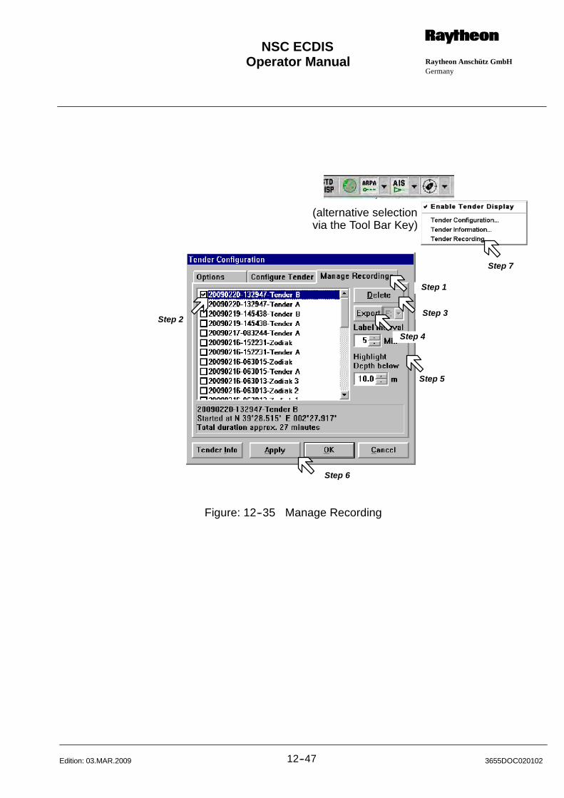
Operator Manual Raytheon Anschütz GmbHGermany
RNSC ECDIS
12--47 3655DOC020102Edition: 03.MAR.2009
(alternative selectionvia the Tool Bar Key)
Step 2
Step 5
Step 6
Step 3
Step 4
Step 1
Step 7
Figure: 12--35 Manage Recording

Operator Manual
12--483655DOC020102 Edition: 03.MAR.2009
12.1.12.2 Tender Information
The active channel will be shown on the caption bar of the Tender Information
Dialog.
Procedure: Tender Information (Figure: 12--36)
Step 1 Select Tender Configuration.. from the Integration menu or as an
alternativly via the Tool Bar Key or by clicking on a Tender symbol in
the sea chart.
The Dialog box appears.
Step 2 To Stop Recording.
Step 3 To Clear All Tender.
Step 4 Change to Tender Options.
(alternative selectionvia the Tool Bar Key)
Step 1
Step 2 Step 3 Step 4
Figure: 12--36 Tender Information
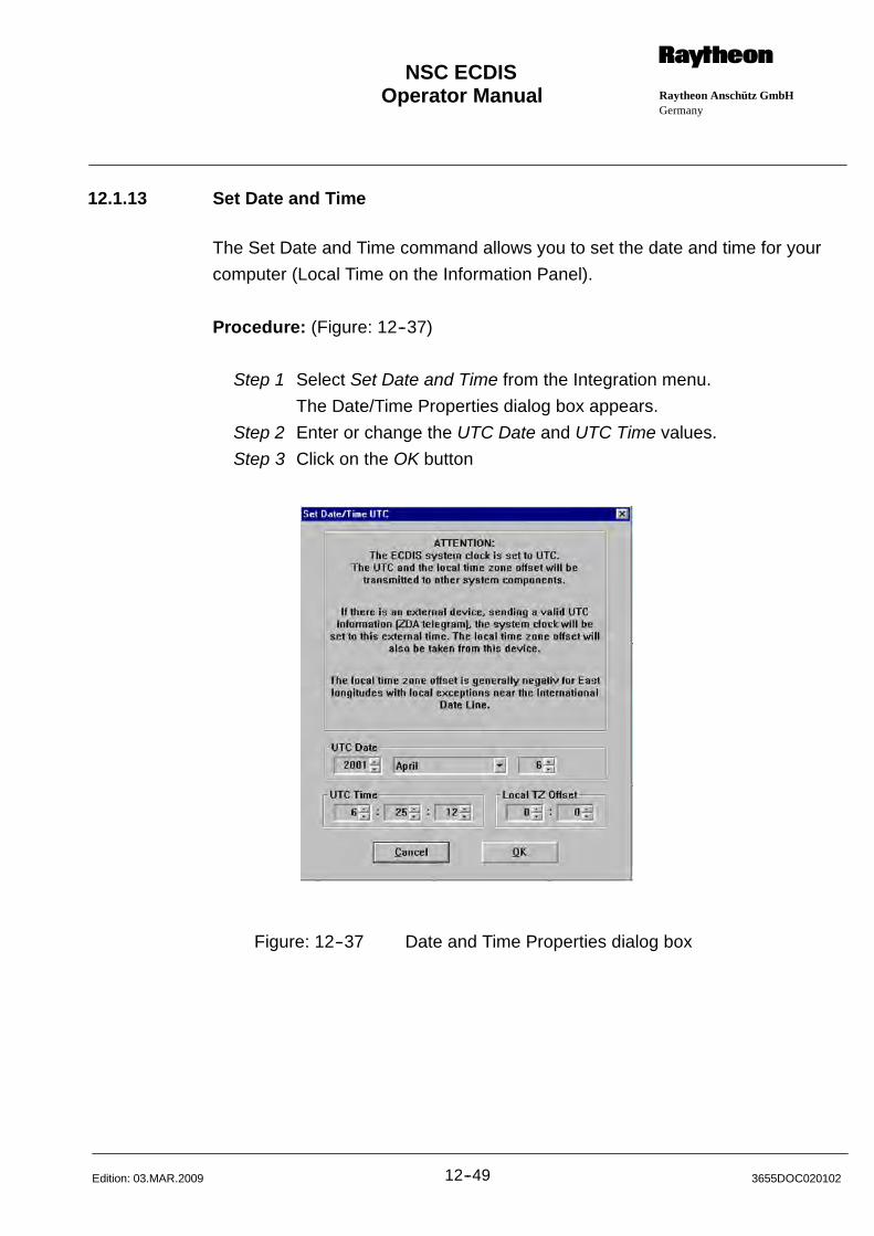
Operator Manual Raytheon Anschütz GmbHGermany
RNSC ECDIS
12--49 3655DOC020102Edition: 03.MAR.2009
12.1.13 Set Date and Time
The Set Date and Time command allows you to set the date and time for your
computer (Local Time on the Information Panel).
Procedure: (Figure: 12--37)
Step 1 Select Set Date and Time from the Integration menu.
The Date/Time Properties dialog box appears.
Step 2 Enter or change the UTC Date and UTC Time values.
Step 3 Click on the OK button
Figure: 12--37 Date and Time Properties dialog box
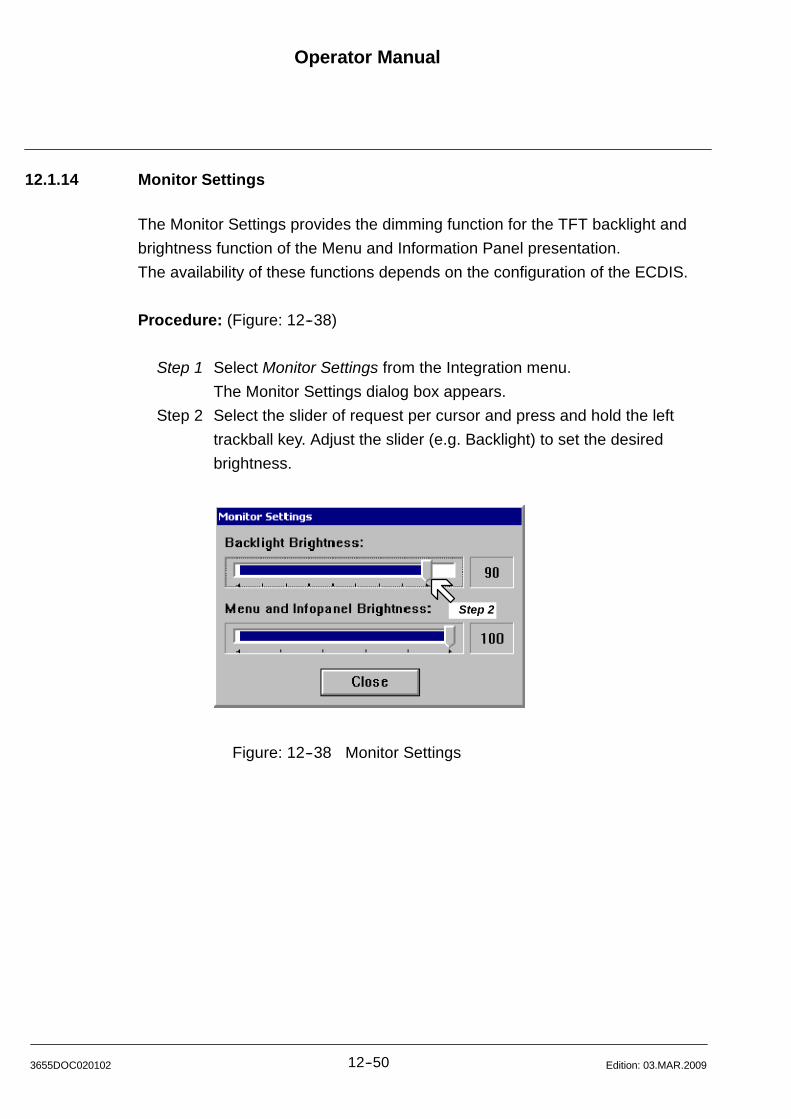
Operator Manual
12--503655DOC020102 Edition: 03.MAR.2009
12.1.14 Monitor Settings
The Monitor Settings provides the dimming function for the TFT backlight and
brightness function of the Menu and Information Panel presentation.
The availability of these functions depends on the configuration of the ECDIS.
Procedure: (Figure: 12--38)
Step 1 Select Monitor Settings from the Integration menu.
The Monitor Settings dialog box appears.
Step 2 Select the slider of request per cursor and press and hold the left
trackball key. Adjust the slider (e.g. Backlight) to set the desired
brightness.
Step 2
Figure: 12--38 Monitor Settings
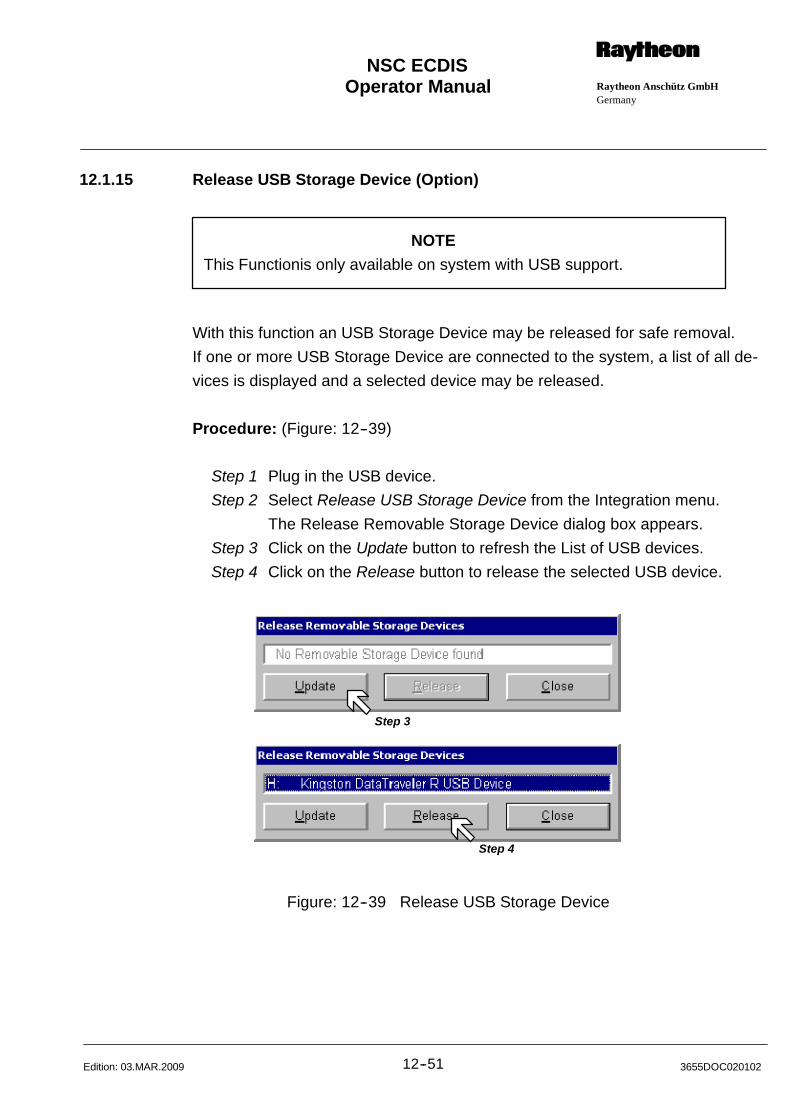
Operator Manual Raytheon Anschütz GmbHGermany
RNSC ECDIS
12--51 3655DOC020102Edition: 03.MAR.2009
12.1.15 Release USB Storage Device (Option)
NOTE
This Functionis only available on system with USB support.
With this function an USB Storage Device may be released for safe removal.
If one or more USB Storage Device are connected to the system, a list of all de-
vices is displayed and a selected device may be released.
Procedure: (Figure: 12--39)
Step 1 Plug in the USB device.
Step 2 Select Release USB Storage Device from the Integration menu.
The Release Removable Storage Device dialog box appears.
Step 3 Click on the Update button to refresh the List of USB devices.
Step 4 Click on the Release button to release the selected USB device.
Step 3
Step 4
Figure: 12--39 Release USB Storage Device

Operator Manual
12--523655DOC020102 Edition: 03.MAR.2009
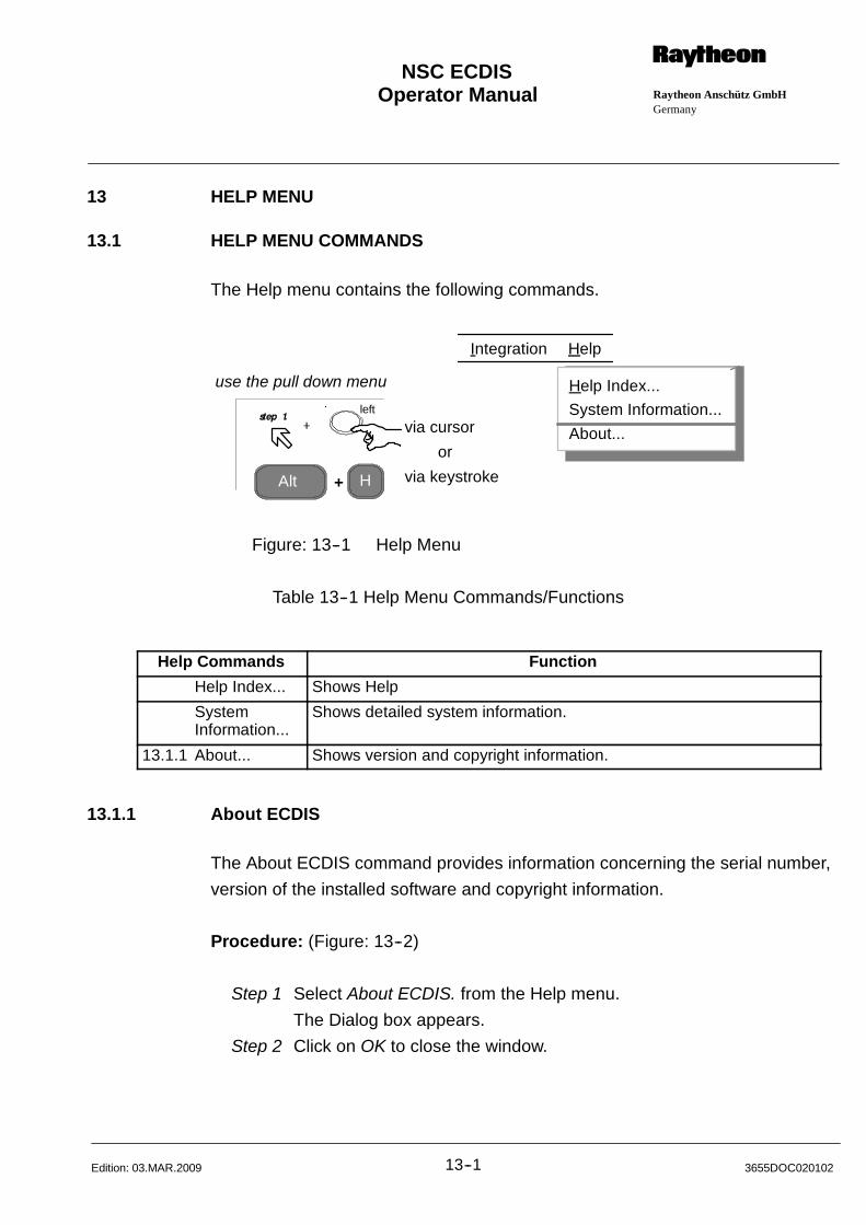
Operator Manual Raytheon Anschütz GmbHGermany
RNSC ECDIS
13--1 3655DOC020102Edition: 03.MAR.2009
13 HELP MENU
13.1 HELP MENU COMMANDS
The Help menu contains the following commands.
Alt H
via cursor
via keystroke
or
+
use the pull down menu
Integration Help
Help Index...
System Information...
About...
left
Figure: 13--1 Help Menu
Table 13--1 Help Menu Commands/Functions
Help Commands Function
Help Index... Shows Help
SystemInformation...
Shows detailed system information.
13.1.1 About... Shows version and copyright information.
13.1.1 About ECDIS
The About ECDIS command provides information concerning the serial number,
version of the installed software and copyright information.
Procedure: (Figure: 13--2)
Step 1 Select About ECDIS. from the Help menu.
The Dialog box appears.
Step 2 Click on OK to close the window.
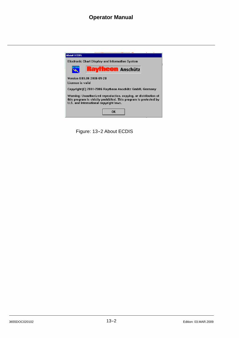
Operator Manual
13--23655DOC020102 Edition: 03.MAR.2009
Figure: 13--2 About ECDIS
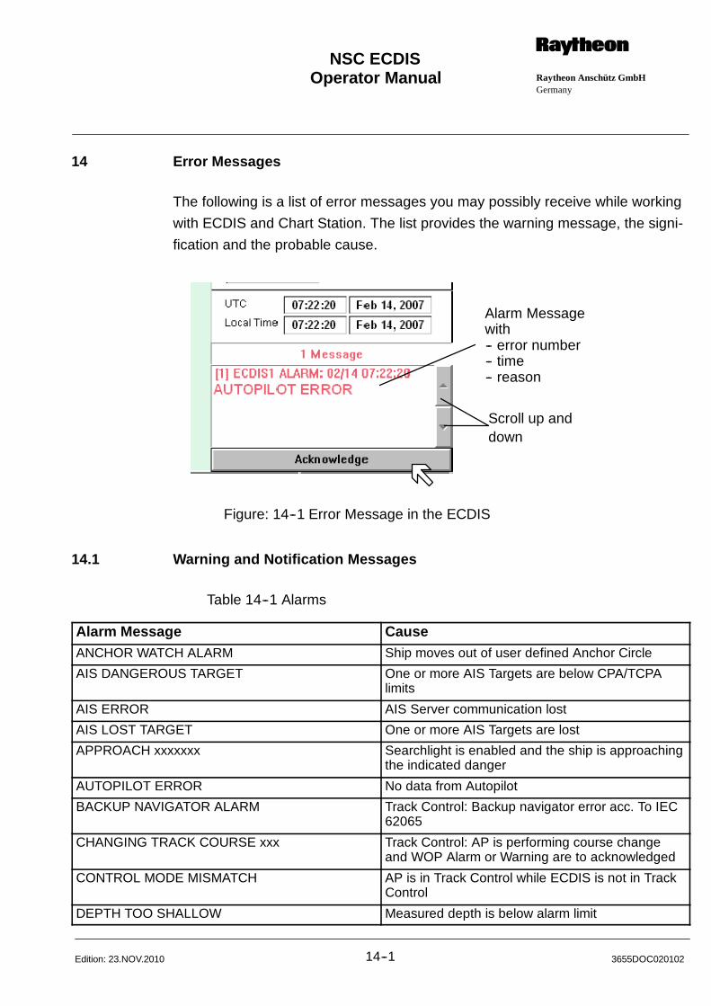
Operator Manual Raytheon Anschütz GmbHGermany
RNSC ECDIS
14--1 3655DOC020102Edition: 23.NOV.2010
14 Error Messages
The following is a list of error messages you may possibly receive while working
with ECDIS and Chart Station. The list provides the warning message, the signi-
fication and the probable cause.
Alarm Messagewith-- error number-- time-- reason
Scroll up anddown
Figure: 14--1 Error Message in the ECDIS
14.1 Warning and Notification Messages
Table 14--1 Alarms
Alarm Message CauseANCHOR WATCH ALARM Ship moves out of user defined Anchor Circle
AIS DANGEROUS TARGET One or more AIS Targets are below CPA/TCPAlimits
AIS ERROR AIS Server communication lost
AIS LOST TARGET One or more AIS Targets are lost
APPROACH xxxxxxx Searchlight is enabled and the ship is approachingthe indicated danger
AUTOPILOT ERROR No data from Autopilot
BACKUP NAVIGATOR ALARM Track Control: Backup navigator error acc. To IEC62065
CHANGING TRACK COURSE xxx Track Control: AP is performing course changeand WOP Alarm or Warning are to acknowledged
CONTROL MODE MISMATCH AP is in Track Control while ECDIS is not in TrackControl
DEPTH TOO SHALLOW Measured depth is below alarm limit
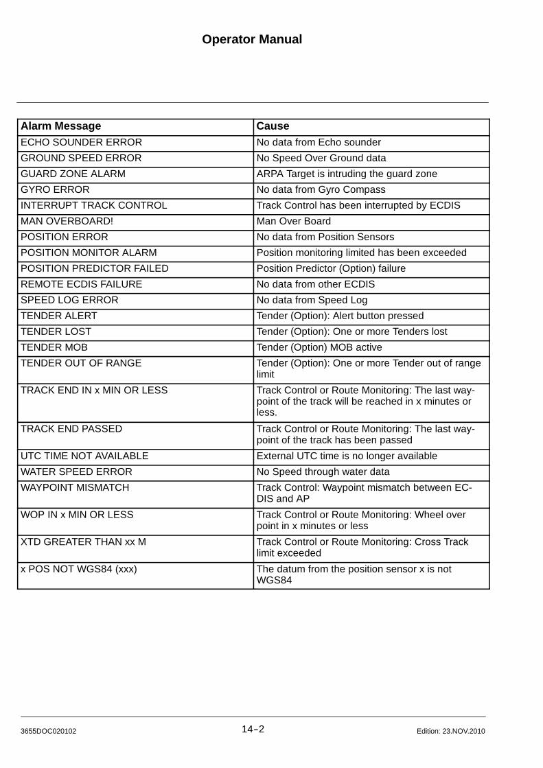
Operator Manual
14--23655DOC020102 Edition: 23.NOV.2010
Alarm Message CauseECHO SOUNDER ERROR No data from Echo sounder
GROUND SPEED ERROR No Speed Over Ground data
GUARD ZONE ALARM ARPA Target is intruding the guard zone
GYRO ERROR No data from Gyro Compass
INTERRUPT TRACK CONTROL Track Control has been interrupted by ECDIS
MAN OVERBOARD! Man Over Board
POSITION ERROR No data from Position Sensors
POSITION MONITOR ALARM Position monitoring limited has been exceeded
POSITION PREDICTOR FAILED Position Predictor (Option) failure
REMOTE ECDIS FAILURE No data from other ECDIS
SPEED LOG ERROR No data from Speed Log
TENDER ALERT Tender (Option): Alert button pressed
TENDER LOST Tender (Option): One or more Tenders lost
TENDER MOB Tender (Option) MOB active
TENDER OUT OF RANGE Tender (Option): One or more Tender out of rangelimit
TRACK END IN x MIN OR LESS Track Control or Route Monitoring: The last way-point of the track will be reached in x minutes orless.
TRACK END PASSED Track Control or Route Monitoring: The last way-point of the track has been passed
UTC TIME NOT AVAILABLE External UTC time is no longer available
WATER SPEED ERROR No Speed through water data
WAYPOINT MISMATCH Track Control: Waypoint mismatch between EC-DIS and AP
WOP IN x MIN OR LESS Track Control or Route Monitoring: Wheel overpoint in x minutes or less
XTD GREATER THAN xx M Track Control or Route Monitoring: Cross Tracklimit exceeded
x POS NOT WGS84 (xxx) The datum from the position sensor x is notWGS84

Operator Manual Raytheon Anschütz GmbHGermany
RNSC ECDIS
14--3 3655DOC020102Edition: 15.JAN.2013
Table 14--2 Warnings
Warning Message CauseARCS CHART HAS WARNINGS The currently displayed ARCS chart has caused
warnings. See ARCS Options -- Chart Warningsfor details
AUTOPILOT NOT READY AP is not ready for Track Control operation
CHART xxxxxxxx OUT OF DATE The displayed ENC chart xxxxxxxx is out of date.Update your charts via Charts -- Update
CM93/3 CHART LICENSE WILL EXPIRE A CM93/3 license will expire in less than a month
CONTROL MODE RESET REMOTELY Track Control has been terminated from remote(AP operator unit)
DEAD RECKON NOT AVAILABLE Unable to perform Dead Reckoning due to missinginput
ECDIS IS IN SETUP MODE ECDIS is in service mode
GPS HDOP OUT OF RANGE HDOP exceed configured limit
GPS NOT SENDING NSATS OR HDOP GPS does not send HDOP or number of satellites
GPS TOO FEW SATELLITES GPS number of satellites is below the configuredminimum
LOST DGPS SWITCHING TO GPS Lost differential GPS status
NAVTEX: SAR MSG RECEIVED New SAR message received via NavTex
NO OFFICIAL CHART USE PAPER CHART No official ENC Chart available at the current posi-tion
NOT ENOUGH WAYPOINTS Track Control: Initialisation error
AUTOPILOT Track Control: NP203x or NP5500 Initialisation er-ror
PASSED WAYPT: xxx Track Control: Passed waypoint without passingthe wheel over point
POSITION LEAP FROM POS DEVICE The selected position receiver jumped beyond theconfigured limit
POSITION OFFSET IS APPLIED A manual position offset is applied.See Ship -- Position Offset
RADAR SIGNAL LOST Radar Overlay (Option): No Radar signal
SHIP LEAVING ARCS CHART Own ship will leave the displayed ARCS chart inless than 2 minutes
SWITCHING TO DEAD RECKONING Dead Reckoning has been selected due to posi-tion sensor failure
TRACK CANCELED NO ACTIVATION Track Control (ASSA Autopilot only): No activationfrom ASSA
USE DEEPER SAFETY CONT xxx The selected safety contour is not available fromthe currently displayed chart
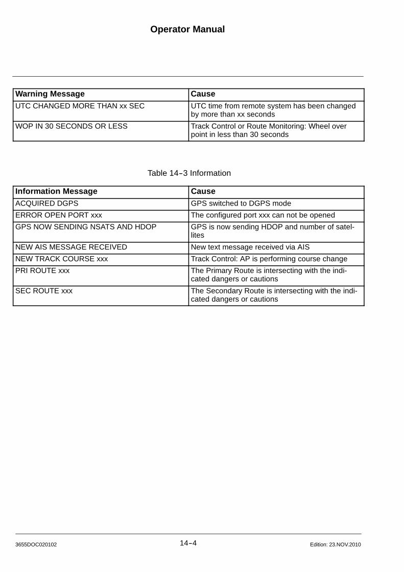
Operator Manual
14--43655DOC020102 Edition: 23.NOV.2010
Warning Message CauseUTC CHANGED MORE THAN xx SEC UTC time from remote system has been changed
by more than xx seconds
WOP IN 30 SECONDS OR LESS Track Control or Route Monitoring: Wheel overpoint in less than 30 seconds
Table 14--3 Information
Information Message CauseACQUIRED DGPS GPS switched to DGPS mode
ERROR OPEN PORT xxx The configured port xxx can not be opened
GPS NOW SENDING NSATS AND HDOP GPS is now sending HDOP and number of satel-lites
NEW AIS MESSAGE RECEIVED New text message received via AIS
NEW TRACK COURSE xxx Track Control: AP is performing course change
PRI ROUTE xxx The Primary Route is intersecting with the indi-cated dangers or cautions
SEC ROUTE xxx The Secondary Route is intersecting with the indi-cated dangers or cautions
Operator Manual Raytheon Anschütz GmbHGermany
RNSC ECDIS
15--1 3655DOC020102Edition: 03.MAR.2008
15 Back--up arrangement
15.1 Introduction
(Source of excerpts (BSH S33/N24) 1/01)
Following requirements must be met to allow the official paper chart on board of
seagoing vessels under the German Flag to be completely replaced by an
ECDIS system:
To ensure safe navigation in the area of intended operation, the ECDIS must be
operated using official ECDIS data acc. to IHO Standard for Digital Hydrographic
(Special Publication No. 57 Edition 3.0), abbreviated S57 and IHO S--63.
(Item 2)
In case official ECDIS data for the areas of intended operation cannot yet be
made available by the responsible hydrographic services, official raster data in
”RCDS--mode” can be used for navigation as a substitute. For these areas, how-
ever, a reduced set of official and up--to--date paper charts is to be carried on
board the vessel. The selection of these charts is the duty of the captain and
must comprise charts of following scales:
-- for planning an intended voyage or passage:
chart scale: 1 : 750 000 to 1 : 1 500 000
-- for performing a planned voyage or passage on the open sea:
chart scale: 1 : 100 000 to 1 : 500 000;
-- for performing a planned voyage or passage in coastal waters with
high traffic density or on approach of estuaries and harbours:
chart scale: < 1 : 100 000.
(Item 4)
The ECDIS must be protected against possible failure using appropriate back--
ups to ensure a safe completion of the voyage.
The current regulations allow following solutions:

Operator Manual
15--23655DOC020102 Edition: 03.MAR.2009
a) a duplication of the ECDIS
b) carrying of a complete set of official and up--to--date paper charts
The carriage requirements under Item 2 for a reduced set of official and up--to--
date charts when using the official raster data in RCDS mode
remain unaffected by this. If the requirement for a back--up is met by the
option Item 4.b, the reduced set of charts can, of course, be considered as part
of the back--up.
15.1.1 Back--up ECDIS Version
The back--up version comprises two identical ECDIS units (Console or Table Top
Version) and a DIGITIZER (see Annex -- 8).
With the exception of the AUTOPILOT, both ECDIS units are separately supplied
with the required sensor data (Gyro Compass, Log, GPS) via the Com 1....6 In-
terfaces.
The AUTOPILOT is usually connected to the ECDIS in the operational area.
In case a discrepancy occurs within the tracking ”ECDIS and AUTOPILOT”,
switch over to another tracking mode.
Sea Charts
The ECDIS is rated for taking over and displaying different digitized charts. For
non--officially approved chart formats an official redundant set of paper charts
shall be provided (chapter 15.1).
Position DisplayThe redundant position display is ensured by a separate sensor feeding.
Route Planning
Route Planning with the ECDIS
Routes may only be planned and navigated using officially approved and digi-
tized charts (S57) and in connection with an autopilot. The planning of routes
can be effected via both ECDIS systems. The ECDIS transfers the routes auto-
matically via the Ethernet.
Operator Manual Raytheon Anschütz GmbHGermany
RNSC ECDIS
15--3 3655DOC020102Edition: 03.MAR.2008
Route Planning with the Digitizer
The Digitizer is hereby used for planning official routes. Planned routes are
transferred to the ECDIS where they are managed by their designation.
15.1.2 Planning Station Version
The Planning Station Version consists of 1 ECDIS unit (Console or Table Top
Version), a Personal Computer (PC) or Table Top Version and a DIGITIZER (see
Annex – 8).
Sea Charts
The ECDIS is rated for taking over and displaying different digitized charts. For
non--officially approved chart formats an official redundant set of paper charts
shall be provided (chapter 15.1).
Position Display
The redundant position display is ensured by a separate sensor feeding.
Route Planning
Route Planning with the ECDIS.
Routes may only be planned and navigated using officially approved and digi-
tized charts (S57) and in connection with an autopilot. The planning of routes
can be effected via both ECDIS systems. The ECDIS transfers the routes auto-
matically via the Ethernet.
Route Planning with the Digitizer
The Digitizer is used for planning official routes. Planned routes are transferred
to the ECDIS where they are managed by their designation.

Operator Manual
15--43655DOC020102 Edition: 03.MAR.2009

Operator Manual Raytheon Anschütz GmbHGermany
RNSC ECDIS
16--1 3655DOC020102Edition: 23.FEB.2012
16 Weather Overlay (Option)
16.1 Introduction
The Weather Overlay (WO) transparently shows actual, historic or future
weather information.
Gridded binary data available in WMO -- GRIB (FM 92--IX Ext.) coded files is
read, decoded and shown with symbols and numeric values.
The following weather products are currently supported:
Wind components (direction & force) and gust (10 meters above ground)
Wind components (direction & force) (surface)
Mean sea level pressure
Air Temperature (2 meters above ground)
Current components (direction & force)
Significant height, combined wind waves + swell
Mean direction of wind waves
Mean period of wind waves
Total cloud cover
Wetterwelt combined weather symbol
NOTE
In the absence of ’10 meter wind components’ the surface wind is shown
when available.
The weather data is shown as a regular grid on top of all other ECDIS display
layers. Depending on chart resolution, GRIB data resolution and actual viewing
area, the weather grid locations are selected to show as most as possible
weather information, thereby avoid hiding other important ECDIS information.
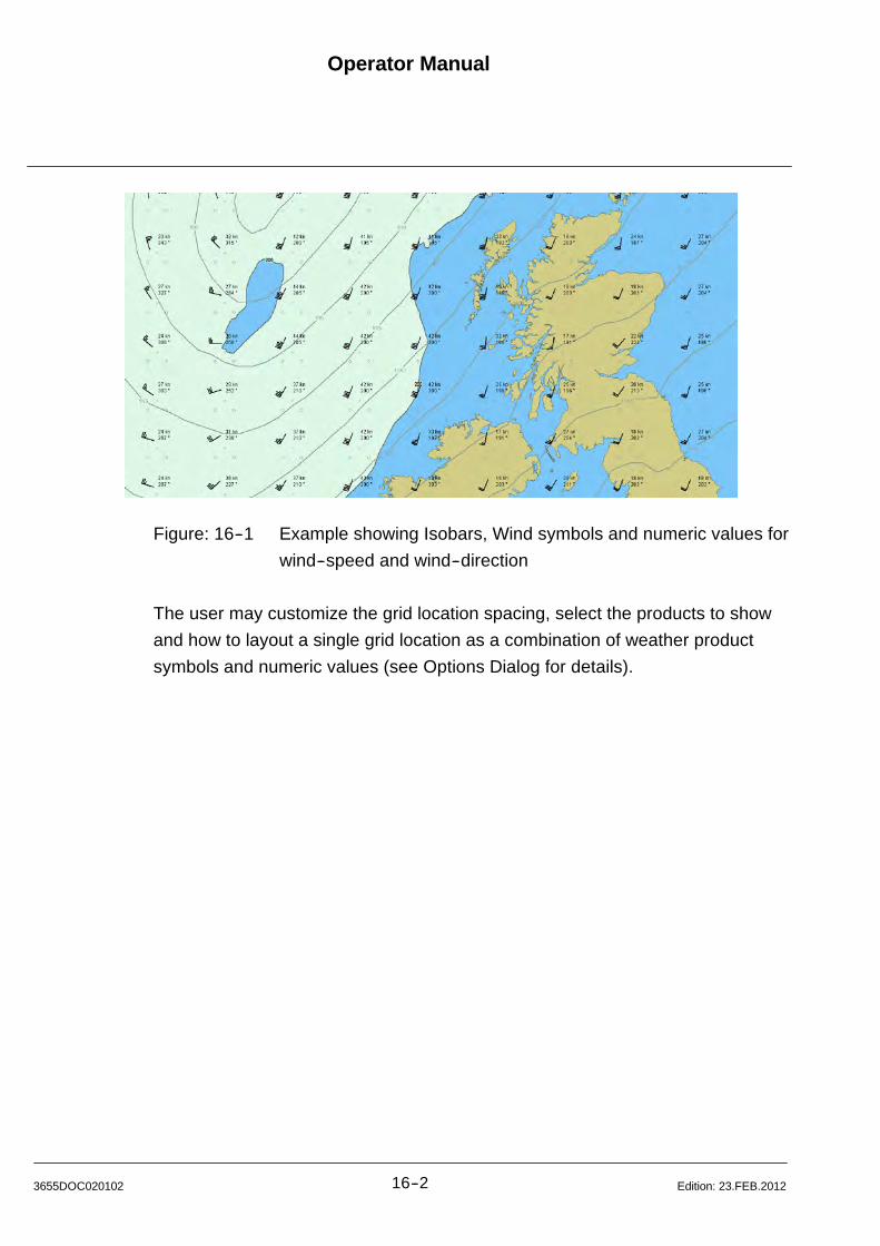
Operator Manual
16--23655DOC020102 Edition: 23.FEB.2012
Figure: 16--1 Example showing Isobars, Wind symbols and numeric values for
wind--speed and wind--direction
The user may customize the grid location spacing, select the products to show
and how to layout a single grid location as a combination of weather product
symbols and numeric values (see Options Dialog for details).
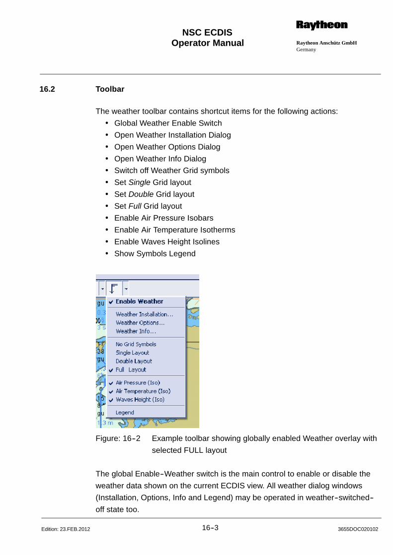
Operator Manual Raytheon Anschütz GmbHGermany
RNSC ECDIS
16--3 3655DOC020102Edition: 23.FEB.2012
16.2 Toolbar
The weather toolbar contains shortcut items for the following actions:
Global Weather Enable Switch
Open Weather Installation Dialog
Open Weather Options Dialog
Open Weather Info Dialog
Switch off Weather Grid symbols
Set Single Grid layout
Set Double Grid layout
Set Full Grid layout
Enable Air Pressure Isobars
Enable Air Temperature Isotherms
Enable Waves Height Isolines
Show Symbols Legend
Figure: 16--2 Example toolbar showing globally enabled Weather overlay with
selected FULL layout
The global Enable--Weather switch is the main control to enable or disable the
weather data shown on the current ECDIS view. All weather dialog windows
(Installation, Options, Info and Legend) may be operated in weather--switched--
off state too.

Operator Manual
16--43655DOC020102 Edition: 23.FEB.2012
16.3 Installation Dialog
The installation dialog shows a list of currently loaded GRIB data files. File op-
erations are defined to modify the priority, switch the enable attribute, delete or
purge files, select a file for inspection and auto follow the ECDIS view to display
the geographic area of the current selected file.
Figure: 16--3 Example with 8 loaded GRIB files, average validity of 1 day and
10 hours, Med_W_Race_MS_01_42h.grb with future validity,
and one file with expired validity, a currently selected and en
abled GRIB file Med_E_Race_01_42h_29112011.grb, detailed
information in the lower area for the selected file
The upper area shows all currently loaded GRIB files in descending priority or-
der.
Whenever weather data is available from multiple GRIB files (with identical type,
validity and geographic location) the GRIB file with higher priority is selected to
grab the weather data.

Operator Manual Raytheon Anschütz GmbHGermany
RNSC ECDIS
16--5 3655DOC020102Edition: 23.FEB.2012
NOTE
When multiple GRIB files are enabled with overlapping geographic
regions, the resulting grid region may not be synchronized to each other.
This effect may be reduced by decreasing the view area.
The priority may be changed by moving files up (more priority) or down (less
priority), (1.) selecting a continuous range and (2.) pressing the Up or Down but-
ton.
The Sort button will reorder all files according to the shown start time of all files --
i.e. a newer start time has more priority then an older start time.
To delete files, (1.) select any collection of files and (2.) press the Delete button.
To purge files (expired or invalid), press the Purge button.
To enable or disable a file select the checkbox to the left of the file -- a disabled
file will temporarily not be used to access any GRIB data.
Enable the Auto--Follow checkbox to force the ECDIS view to display the geo-
graphic region of a selected GRIB file -- the area is shown bounded by an
orange (bounded) rectangle.
In the lower area detailed information about a selected GRIB file is shown:
Source the emitting center and sub--center
Geo Area the geographic region of the data
Grid Spacing the grid spacing in units of degrees (0.400 horizontal and
vertical in the example)
Forecast Times the overall forecast time range
Products contained products with abbreviated short names and
description
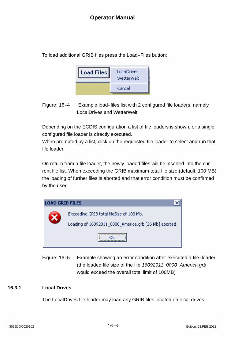
Operator Manual
16--63655DOC020102 Edition: 23.FEB.2012
To load additional GRIB files press the Load--Files button:
Figure: 16--4 Example load--files list with 2 configured file loaders, namely
LocalDrives and WetterWelt
Depending on the ECDIS configuration a list of file loaders is shown, or a single
configured file loader is directly executed.
When prompted by a list, click on the requested file loader to select and run that
file loader.
On return from a file loader, the newly loaded files will be inserted into the cur-
rent file list. When exceeding the GRIB maximum total file size (default: 100 MB)
the loading of further files is aborted and that error condition must be confirmed
by the user.
Figure: 16--5 Example showing an error condition after executed a file--loader
(the loaded file size of the file 16092011_0000_America.grb
would exceed the overall total limit of 100MB)
16.3.1 Local Drives
The LocalDrives file loader may load any GRIB files located on local drives.

Operator Manual Raytheon Anschütz GmbHGermany
RNSC ECDIS
16--7 3655DOC020102Edition: 23.FEB.2012
Figure: 16--6 Example with selected USB folder J:/Weather_Download,
showing 4 selected files with varying sizes
The Load button will copy and load the selected files with an optional overwrite
warning message when trying to overwrite an already existing file.
The Load&Overwrite button will copy and load the selected files without warning
messages.
In any case the dialog is closed and the control dialog will be reopened showing
the newly loaded files -- optionally with an intermediate file progress indication.
16.3.2 WetterWelt -- Catalog
The Catalog WetterWelt file loader may load GRIB files remotely from a Wetter-
Welt server.
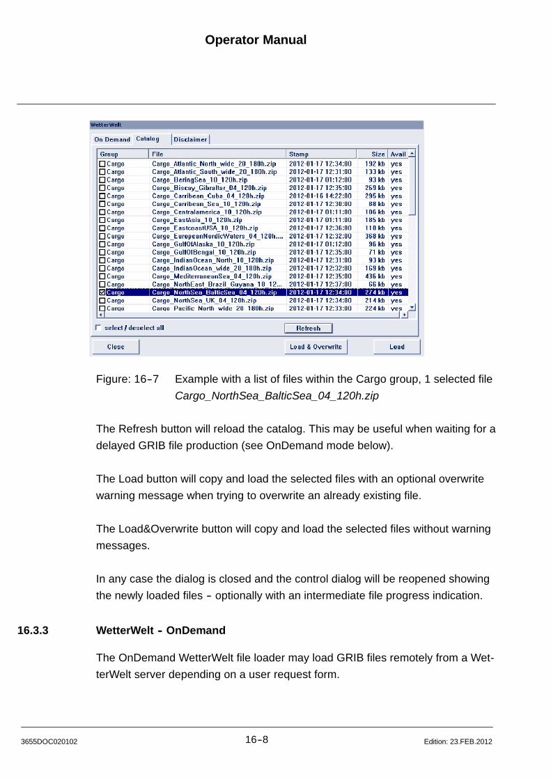
Operator Manual
16--83655DOC020102 Edition: 23.FEB.2012
Figure: 16--7 Example with a list of files within the Cargo group, 1 selected file
Cargo_NorthSea_BalticSea_04_120h.zip
The Refresh button will reload the catalog. This may be useful when waiting for a
delayed GRIB file production (see OnDemand mode below).
The Load button will copy and load the selected files with an optional overwrite
warning message when trying to overwrite an already existing file.
The Load&Overwrite button will copy and load the selected files without warning
messages.
In any case the dialog is closed and the control dialog will be reopened showing
the newly loaded files -- optionally with an intermediate file progress indication.
16.3.3 WetterWelt -- OnDemand
The OnDemand WetterWelt file loader may load GRIB files remotely from a Wet-
terWelt server depending on a user request form.

Operator Manual Raytheon Anschütz GmbHGermany
RNSC ECDIS
16--9 3655DOC020102Edition: 23.FEB.2012
Figure: 16--8 Example with Package Selection named Weather Worldwide
Highres, some selected products, geographic region, 3 days
forecast, 6 hours stepping, 0.4 degrees resolution and an
expected file size of 424 kb
On startup the currently viewed ECDIS region is taken as base input to Top/Left
and Bottom/Right coordinate edit fields. Any valid geographic region may be se-
lected not exceeding 180 degrees longitude range.
The Package Selection list contains available packages defined by WetterWelt
and a user selectable entry which allows free changing of Forecast Days, Fore-
cast Step and Grid Resolution parameters.
Within a predefined package, no changes are allowed to Forecast Step and
Forecast Resolution, while the Forecast Days may still be changed within a pre-
defined range.
The user selectable ranges are:
Forecast Days 1 to 10 days
Forecast Step 1, 3, 6 and 12 hours
Grid Resolution 0.100, 0.125, 0.400, 1.000 and 2.000 degrees
All listed products may be selected or de--deselected. But always inspect the re-
turned GRIB file for any warning messages like ”products not available”.
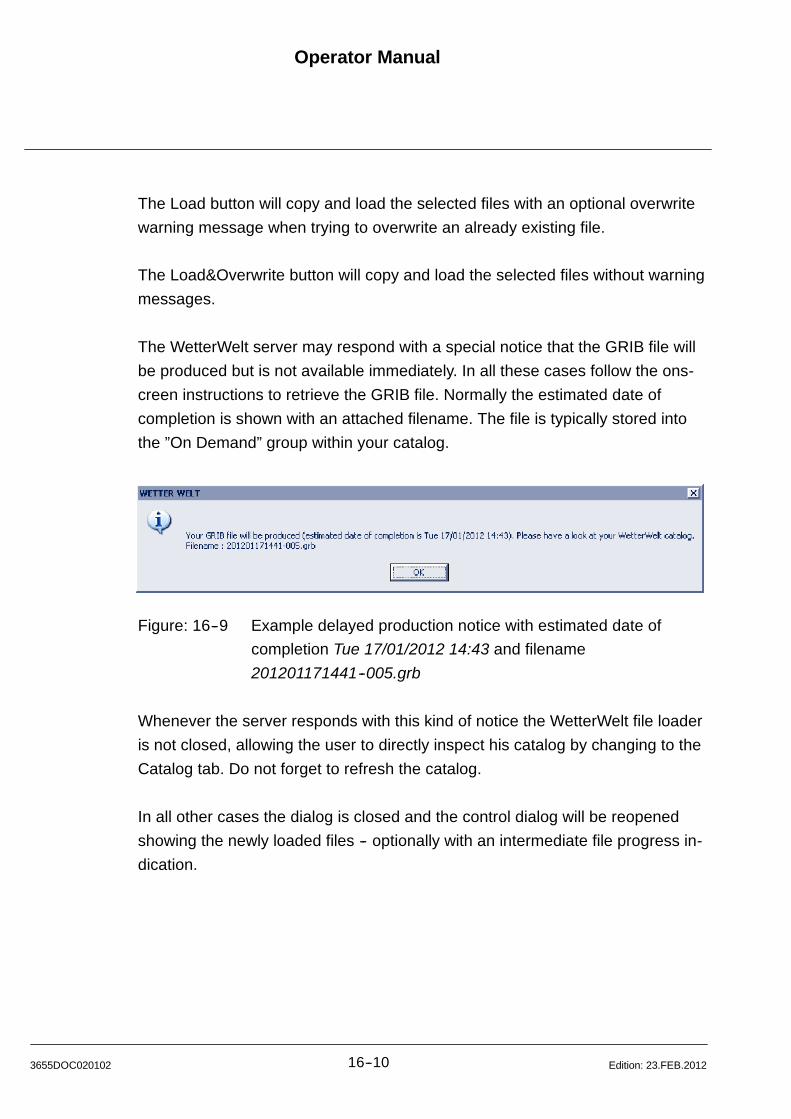
Operator Manual
16--103655DOC020102 Edition: 23.FEB.2012
The Load button will copy and load the selected files with an optional overwrite
warning message when trying to overwrite an already existing file.
The Load&Overwrite button will copy and load the selected files without warning
messages.
The WetterWelt server may respond with a special notice that the GRIB file will
be produced but is not available immediately. In all these cases follow the ons-
creen instructions to retrieve the GRIB file. Normally the estimated date of
completion is shown with an attached filename. The file is typically stored into
the ”On Demand” group within your catalog.
Figure: 16--9 Example delayed production notice with estimated date of
completion Tue 17/01/2012 14:43 and filename
201201171441--005.grb
Whenever the server responds with this kind of notice the WetterWelt file loader
is not closed, allowing the user to directly inspect his catalog by changing to the
Catalog tab. Do not forget to refresh the catalog.
In all other cases the dialog is closed and the control dialog will be reopened
showing the newly loaded files -- optionally with an intermediate file progress in-
dication.
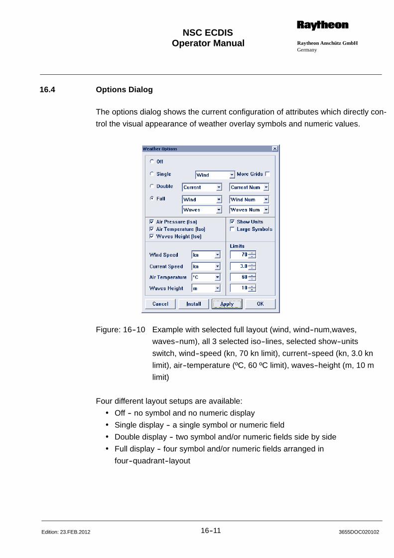
Operator Manual Raytheon Anschütz GmbHGermany
RNSC ECDIS
16--11 3655DOC020102Edition: 23.FEB.2012
16.4 Options Dialog
The options dialog shows the current configuration of attributes which directly con-
trol the visual appearance of weather overlay symbols and numeric values.
Figure: 16--10 Example with selected full layout (wind, wind--num,waves,
waves--num), all 3 selected iso--lines, selected show--units
switch, wind--speed (kn, 70 kn limit), current--speed (kn, 3.0 kn
limit), air--temperature (ºC, 60 ºC limit), waves--height (m, 10 m
limit)
Four different layout setups are available:
Off -- no symbol and no numeric display
Single display -- a single symbol or numeric field
Double display -- two symbol and/or numeric fields side by side
Full display -- four symbol and/or numeric fields arranged in
four--quadrant--layout
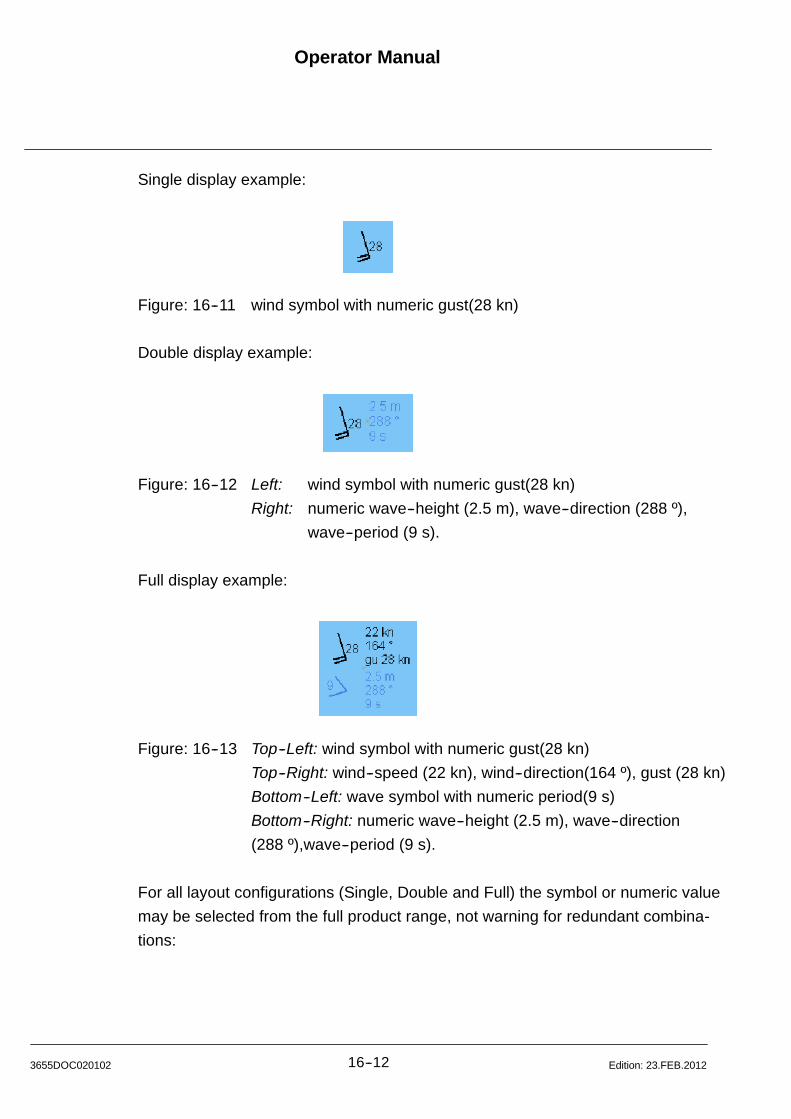
Operator Manual
16--123655DOC020102 Edition: 23.FEB.2012
Single display example:
Figure: 16--11 wind symbol with numeric gust(28 kn)
Double display example:
Figure: 16--12 Left: wind symbol with numeric gust(28 kn)
Right: numeric wave--height (2.5 m), wave--direction (288 º),
wave--period (9 s).
Full display example:
Figure: 16--13 Top--Left: wind symbol with numeric gust(28 kn)
Top--Right: wind--speed (22 kn), wind--direction(164 º), gust (28 kn)
Bottom--Left: wave symbol with numeric period(9 s)
Bottom--Right: numeric wave--height (2.5 m), wave--direction
(288 º),wave--period (9 s).
For all layout configurations (Single, Double and Full) the symbol or numeric value
may be selected from the full product range, not warning for redundant combina-
tions:

Operator Manual Raytheon Anschütz GmbHGermany
RNSC ECDIS
16--13 3655DOC020102Edition: 23.FEB.2012
Figure: 16--14 Example with a full product list for the top/left position of the full
layout
The list of selectable symbols and numeric values:
Wind wind symbol (vane coded to speed, opt. numeric gust)
Wind Num wind numeric values (speed, direction, gust)
Current current symbol (coded to speed)
Current Num current numeric values (speed, direction)
Pres. Num sea level pressure
Temp. Num air temperature
Cloud cloud cover symbol (0--8 octants)
Cloud Num cloud cover numeric percentage value (0--100 %)
Waves waves symbol (coded to height, opt. numeric period)
Waves Num waves numeric values (height, direction, period)
WetterWelt Wetterwelt combined weather symbol
Wind + Curr. current symbol overlayed by wind symbol
Wind + Wave wave symbol overlayed by wind symbol
Curr. + Wave current symbol overlayed by wave symbol
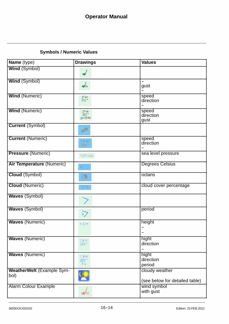
Operator Manual
16--143655DOC020102 Edition: 23.FEB.2012
Symbols / Numeric Values
Name (type) Drawings ValuesWind (Symbol)
Wind (Symbol) --gust--
Wind (Numeric) speeddirection--
Wind (Numeric) speeddirectiongust
Current (Symbol)
Current (Numeric) speeddirection--
Pressure (Numeric) sea level pressure
Air Temperature (Numeric) Degrees Celsius
Cloud (Symbol) octans
Cloud (Numeric) cloud cover percentage
Waves (Symbol)
Waves (Symbol) period
Waves (Numeric) height----
Waves (Numeric) hightdirection--
Waves (Numeric) hightdirectionperiod
WeatherWelt (Example Sym-bol)
cloudy weather
(see below for detailed table)Alarm Colour Example wind symbol
with gust
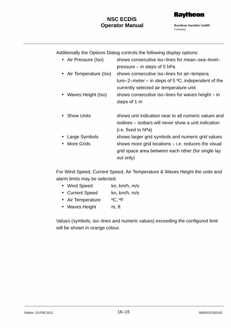
Operator Manual Raytheon Anschütz GmbHGermany
RNSC ECDIS
16--15 3655DOC020102Edition: 23.FEB.2012
Additionally the Options Dialog controls the following display options:
Air Pressure (Iso) shows consecutive iso--lines for mean--sea--level--
pressure -- in steps of 5 hPa
Air Temperature (Iso) shows consecutive iso--lines for air--tempera
ture--2--meter -- in steps of 5 ºC, independent of the
currently selected air temperature unit
Waves Height (Iso) shows consecutive iso--lines for waves height -- in
steps of 1 m
Show Units shows unit indication near to all numeric values and
isolines -- isobars will never show a unit indication
(i.e. fixed to hPa)
Large Symbols shows larger grid symbols and numeric grid values
More Grids shows more grid locations -- i.e. reduces the visual
grid space area between each other (for single lay
out only)
For Wind Speed, Current Speed, Air Temperature & Waves Height the units and
alarm limits may be selected:
Wind Speed kn, km/h, m/s
Current Speed kn, km/h, m/s
Air Temperature ºC, ºF
Waves Height m, ft
Values (symbols, iso--lines and numeric values) exceeding the configured limit
will be shown in orange colour.
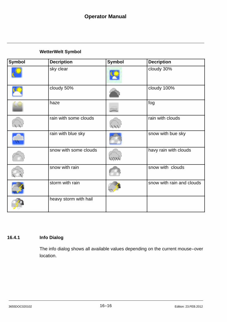
Operator Manual
16--163655DOC020102 Edition: 23.FEB.2012
WetterWelt Symbol
Symbol Decription Symbol Decription
sky clear cloudy 30%
cloudy 50% cloudy 100%
haze fog
rain with some clouds rain with clouds
rain with blue sky snow with bue sky
snow with some clouds havy rain with clouds
snow with rain snow with clouds
storm with rain snow with rain and clouds
heavy storm with hail
16.4.1 Info Dialog
The info dialog shows all available values depending on the current mouse--over
location.
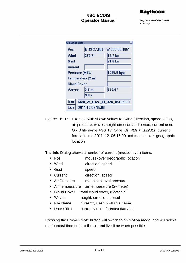
Operator Manual Raytheon Anschütz GmbHGermany
RNSC ECDIS
16--17 3655DOC020102Edition: 23.FEB.2012
Figure: 16--15 Example with shown values for wind (direction, speed, gust),
air pressure, waves height direction and period, current used
GRIB file name Med_W_Race_01_42h_05122011, current
forecast time 2011--12--06 15:00 and mouse--over geographic
location
The Info Dialog shows a number of current (mouse--over) items:
Pos mouse--over geographic location
Wind direction, speed
Gust speed
Current direction, speed
Air Pressure mean sea level pressure
Air Temperature air temperature (2--meter)
Cloud Cover total cloud cover, 8 octants
Waves height, direction, period
File Name currently used GRIB file name
Date / Time currently used forecast date/time
Pressing the Live/Animate button will switch to animation mode, and will select
the forecast time near to the current live time when possible.
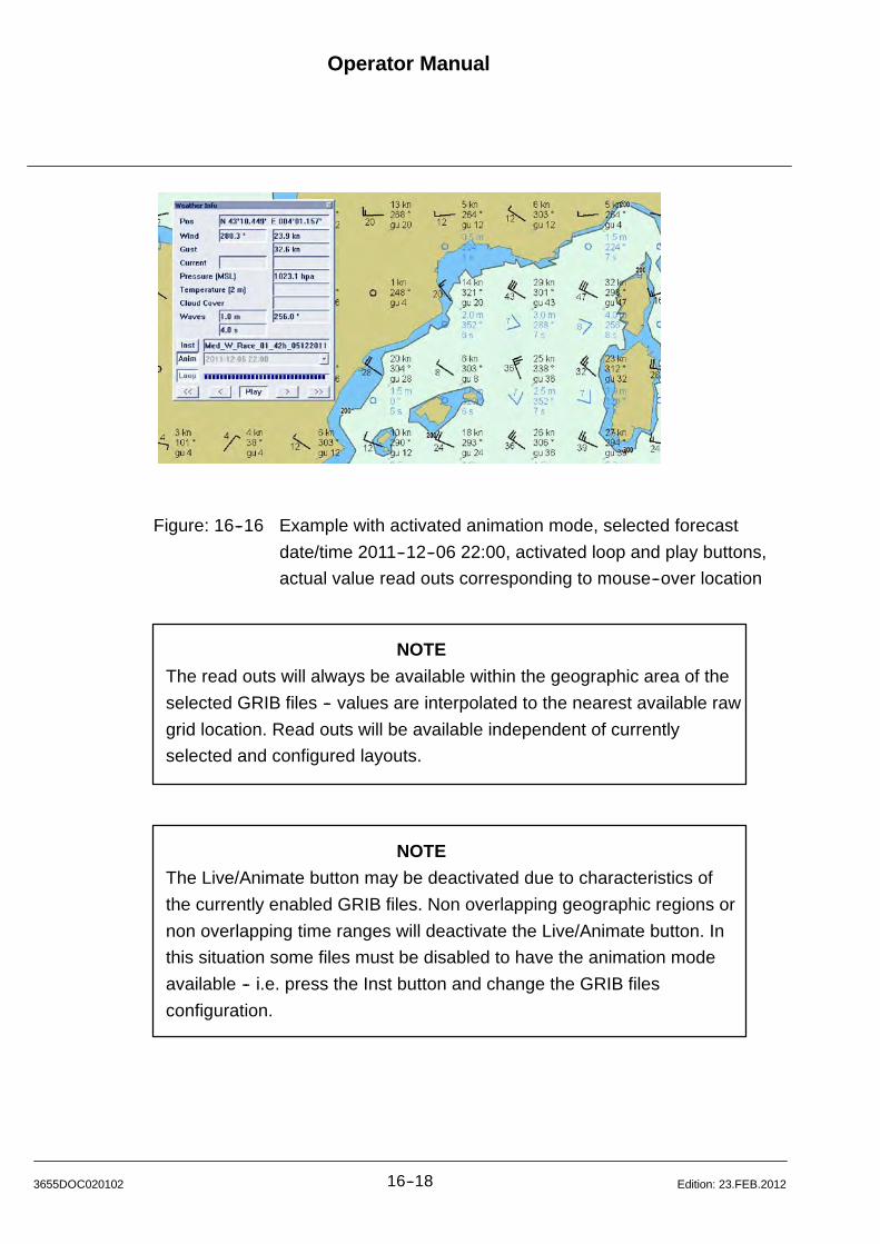
Operator Manual
16--183655DOC020102 Edition: 23.FEB.2012
Figure: 16--16 Example with activated animation mode, selected forecast
date/time 2011--12--06 22:00, activated loop and play buttons,
actual value read outs corresponding to mouse--over location
NOTE
The read outs will always be available within the geographic area of the
selected GRIB files -- values are interpolated to the nearest available raw
grid location. Read outs will be available independent of currently
selected and configured layouts.
NOTE
The Live/Animate button may be deactivated due to characteristics of
the currently enabled GRIB files. Non overlapping geographic regions or
non overlapping time ranges will deactivate the Live/Animate button. In
this situation some files must be disabled to have the animation mode
available -- i.e. press the Inst button and change the GRIB files
configuration.
Operator Manual Raytheon Anschütz GmbHGermany
RNSC ECDIS
16--19 3655DOC020102Edition: 23.FEB.2012
In animation mode the following actions are available:
List selection select the requested forecast time
<< select the previous day
< select the previous time list entry
Play start at the current time list entry and advance to the next entry
every single second
> select the next time list entry
>> select the next day
Loop loop through all time list entries (in play mode only)
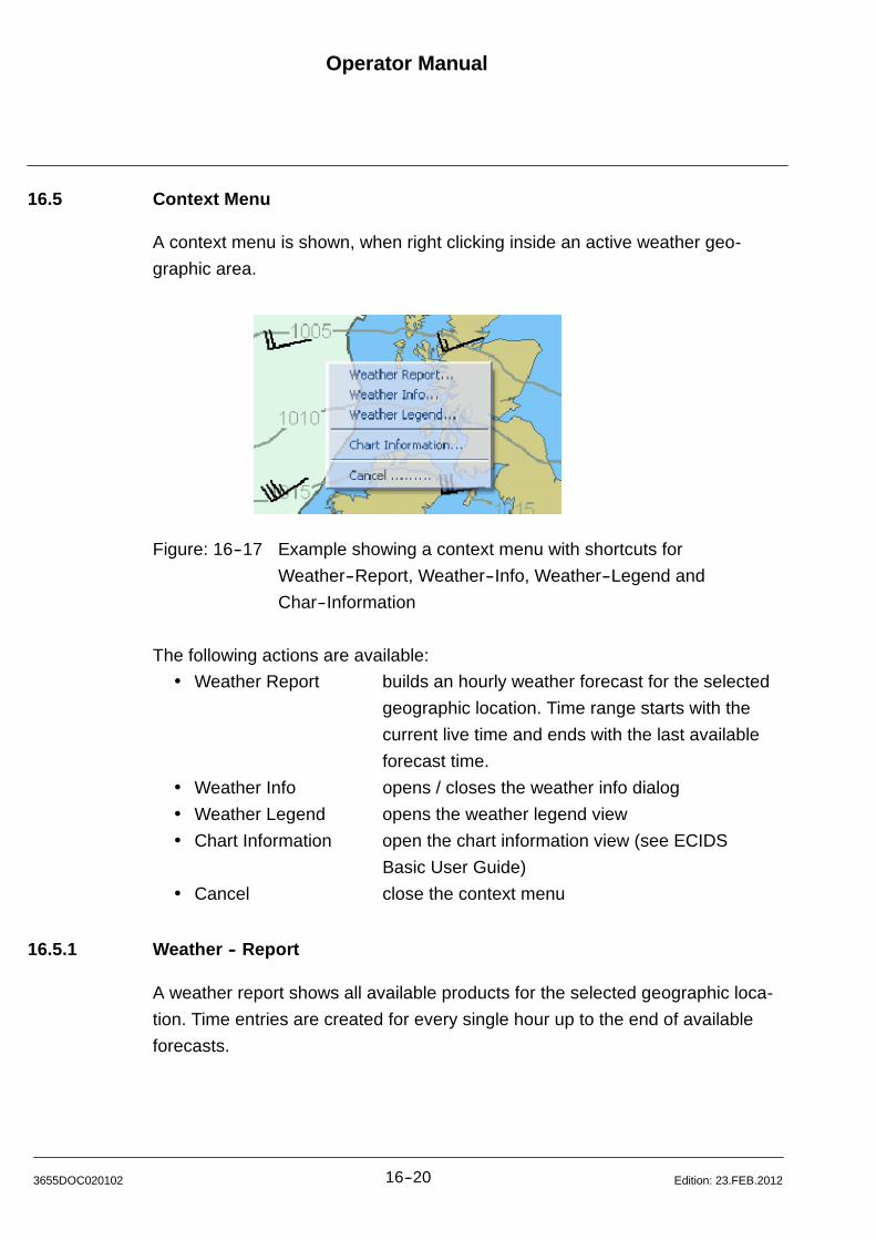
Operator Manual
16--203655DOC020102 Edition: 23.FEB.2012
16.5 Context Menu
A context menu is shown, when right clicking inside an active weather geo-
graphic area.
Figure: 16--17 Example showing a context menu with shortcuts for
Weather--Report, Weather--Info, Weather--Legend and
Char--Information
The following actions are available:
Weather Report� builds an hourly weather forecast for the selected
geographic location. Time range starts with the
current live time and ends with the last available
forecast time.
Weather Info� opens / closes the weather info dialog
Weather Legend� opens the weather legend view
Chart Information� open the chart information view (see ECIDS
Basic User Guide)
Cancel� close the context menu
16.5.1 Weather -- Report
A weather report shows all available products for the selected geographic loca-
tion. Time entries are created for every single hour up to the end of available
forecasts.

Operator Manual Raytheon Anschütz GmbHGermany
RNSC ECDIS
16--21 3655DOC020102Edition: 23.FEB.2012
Figure: 16--18 Example showing a weather report starting on
2012--01--17 14:00
NOTE
Values which do not exist for the specific forecast time are interpolated
over time and marked with an asterisk (*) after the product name.
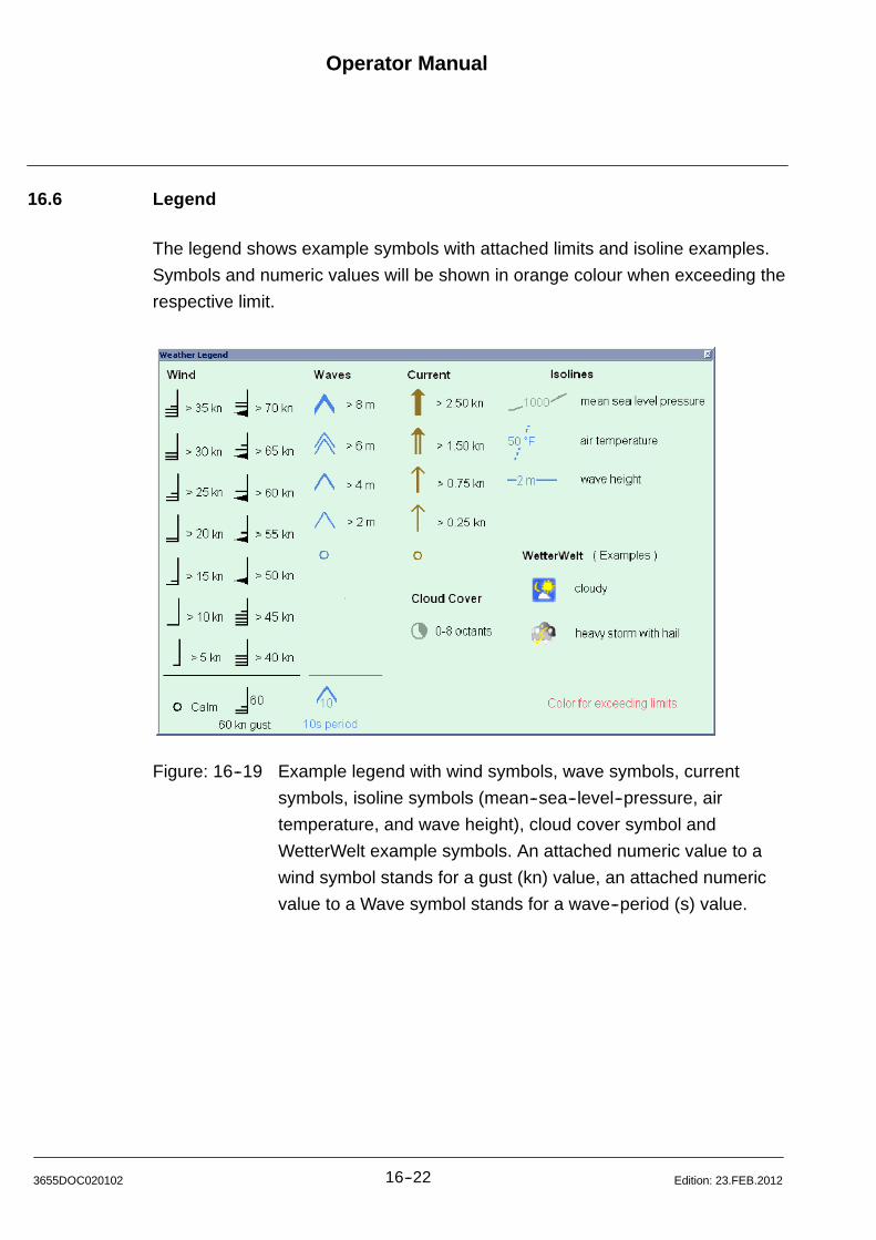
Operator Manual
16--223655DOC020102 Edition: 23.FEB.2012
16.6 Legend
The legend shows example symbols with attached limits and isoline examples.
Symbols and numeric values will be shown in orange colour when exceeding the
respective limit.
Figure: 16--19 Example legend with wind symbols, wave symbols, current
symbols, isoline symbols (mean--sea--level--pressure, air
temperature, and wave height), cloud cover symbol and
WetterWelt example symbols. An attached numeric value to a
wind symbol stands for a gust (kn) value, an attached numeric
value to a Wave symbol stands for a wave--period (s) value.
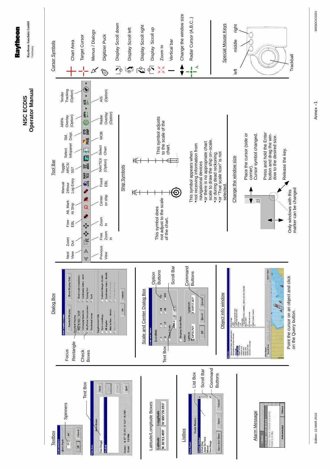
Op
erat
or
Man
ual
Ray
theo
nA
nsch
ütz
Gm
bHG
erm
any
RN
SC
EC
DIS
3655
DO
C02
01E
ditio
n:12
.MA
R.2
010
Ann
ex--1
Spi
nner
s
Text
Box List
Box
Scr
ollB
ar
Com
man
dB
utto
ns
Opt
ion
But
tons
Text
Box
Scr
ollB
ar
Com
man
dB
utto
ns
Che
ckB
oxes
Latit
ude/
Long
itude
Box
es
Foc
us
Rec
tang
leC
hart
Are
a
Targ
etC
urso
r
Dig
itize
rP
uck
Dis
play
Scr
olld
own
Dis
play
Scr
olll
eft
Dis
play
Scr
ollr
ight
Dis
play
Scr
ollu
p
Zoo
mIn
Text
box
List
box
Ala
rmM
essa
ge
Dia
log
Box
Sca
lean
dC
ente
rD
ialo
gB
ox
Tool
Bar
Shi
pS
ymbo
ls
Thi
ssy
mbo
lapp
ears
whe
nn
otre
ceiv
ing
info
rmat
ion
from
navi
gatio
nald
evic
eso
rth
ere
isno
appr
opria
tech
art
scal
eto
draw
the
ship
on--s
cale
.o
rdu
ring
dead
reck
onin
g.o
r“T
rue
scal
eIc
on”
isno
tse
lect
ed.
Thi
ssy
mbo
ladj
usts
toth
esc
ale
ofth
ech
art.
Cur
sor
Sym
bols
Men
us/D
ialo
gs
Thi
ssy
mbo
ldoe
sno
tadj
ustt
oth
esc
ale
ofth
ech
art.
Ver
tical
bar
Obj
ecti
nfo
win
dow
Poi
ntth
ecu
rsor
onan
obje
ctan
dcl
ick
onth
eQ
uery
butto
n.
Cha
nge
the
win
dow
size
Onl
yw
indo
ws
with
this
mar
ker
can
bech
ange
d
Pla
ceth
ecu
rsor
(sid
eor
corn
er).
Cur
sor
sym
bolc
hang
ed.
Pre
ssan
dho
ldth
eE
nter
butto
nan
ddr
agth
ew
in-
dow
toth
ede
sire
dsi
ze.
Rel
ease
the
key.
Cha
nge
the
win
dow
size
Rad
arC
urso
r(A
,B,C
..)
Spe
cial
Mou
seK
eys
left
mid
dle
right
Trac
kbal
l
A
Pre
viou
sV
iew
Nex
tV
iew
Zoo
mIn
Zoo
mO
ut
Cen
ter
onsh
ip
Fre
eE
BL
Fix
edE
BL
Alt.
Mar
kA
tShi
p
Togg
leA
RC
S/
S57
Sel
ect
Cha
rt
Std
.D
ispl
.
Rad
arO
verla
y(O
ptio
n)
Sel
ect
Info
pane
l
AR
PA
Ove
rlay
(Opt
ion)
AIS
(Opt
ion)
Tend
erTr
acki
ng(O
ptio
n)
Fre
eZ
oom
In
Man
ual
24ho
urLo
gE
ntry
MO
BN
AV
TE
X(O
ptio
n)
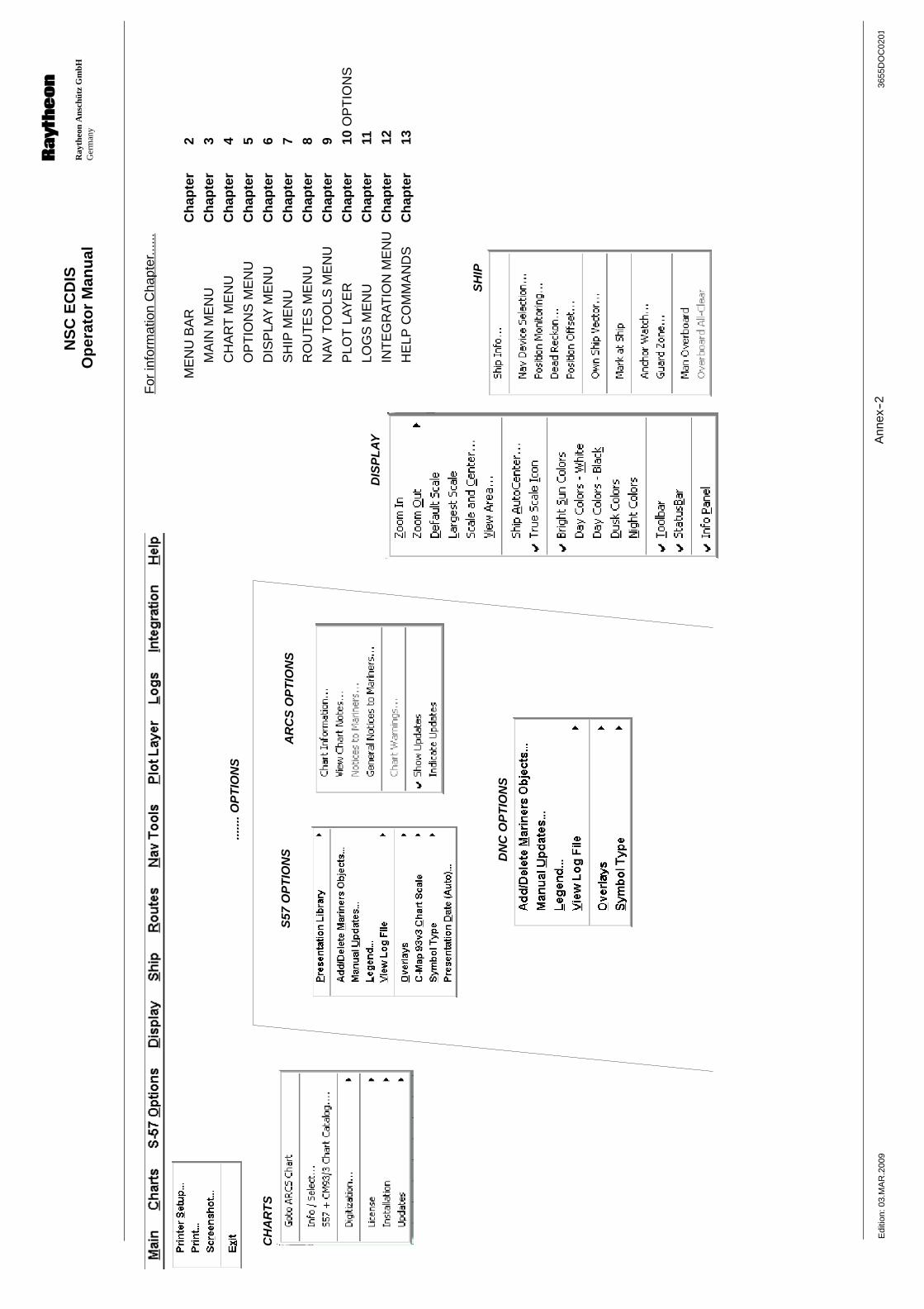
Op
erat
or
Man
ual
Ray
theo
nA
nsch
ütz
Gm
bHG
erm
any
RN
SC
EC
DIS
3655
DO
C02
01E
ditio
n:03
.MA
R.2
009
Ann
ex--2
CH
AR
TS
S57
OP
TIO
NS
DIS
PL
AY
SH
IP
AR
CS
OP
TIO
NS
For
info
rmat
ion
Cha
pter
......
ME
NU
BA
RC
hap
ter
2
MA
INM
EN
UC
hap
ter
3
CH
AR
TM
EN
UC
hap
ter
4
OP
TIO
NS
ME
NU
Ch
apte
r5
DIS
PLA
YM
EN
UC
hap
ter
6
SH
IPM
EN
UC
hap
ter
7
RO
UT
ES
ME
NU
Ch
apte
r8
NA
VT
OO
LSM
EN
UC
hap
ter
9
PLO
TLA
YE
RC
hap
ter
10O
PT
ION
S
LOG
SM
EN
UC
hap
ter
11
INT
EG
RA
TIO
NM
EN
UC
hap
ter
12
HE
LPC
OM
MA
ND
SC
hap
ter
13
DN
CO
PT
ION
S
......
.OP
TIO
NS
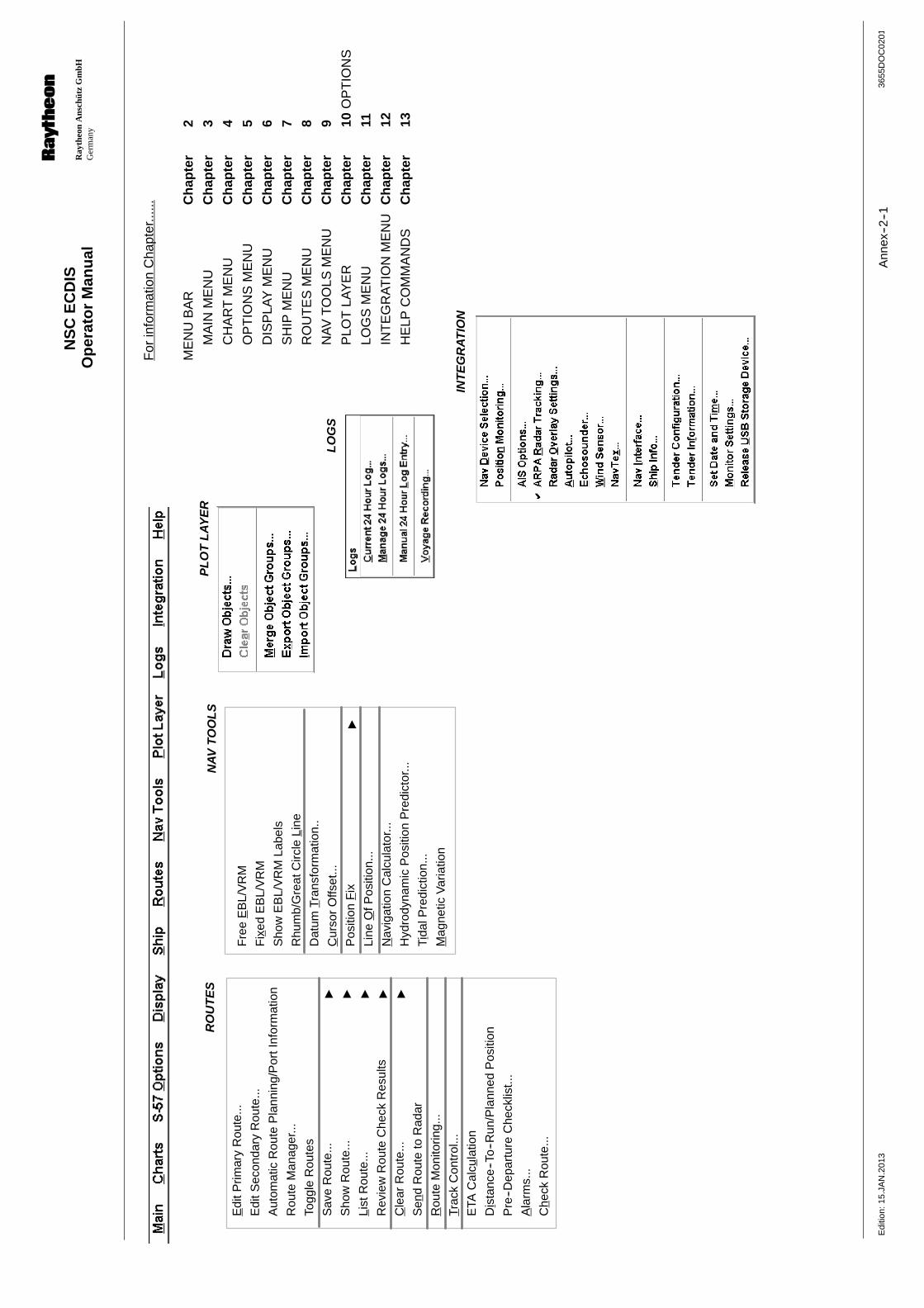
Op
erat
or
Man
ual
Ray
theo
nA
nsch
ütz
Gm
bHG
erm
any
RN
SC
EC
DIS
3655
DO
C02
01E
ditio
n:15
.JA
N.2
013
Ann
ex--2
--1
RO
UT
ES
NA
VT
OO
LS
LO
GS
INT
EG
RA
TIO
N
For
info
rmat
ion
Cha
pter
......
ME
NU
BA
RC
hap
ter
2
MA
INM
EN
UC
hap
ter
3
CH
AR
TM
EN
UC
hap
ter
4
OP
TIO
NS
ME
NU
Ch
apte
r5
DIS
PLA
YM
EN
UC
hap
ter
6
SH
IPM
EN
UC
hap
ter
7
RO
UT
ES
ME
NU
Ch
apte
r8
NA
VT
OO
LSM
EN
UC
hap
ter
9
PLO
TLA
YE
RC
hap
ter
10O
PT
ION
S
LOG
SM
EN
UC
hap
ter
11
INT
EG
RA
TIO
NM
EN
UC
hap
ter
12
HE
LPC
OM
MA
ND
SC
hap
ter
13
PL
OT
LA
YE
R
Fre
eE
BL/
VR
M
Fix
edE
BL/
VR
M
Sho
wE
BL/
VR
MLa
bels
Rhu
mb/
Gre
atC
ircle
L ine
Dat
umT r
ansf
orm
atio
n..
Cur
sor
Offs
et...
Pos
ition
Fix
"
Line
OfP
ositi
on...
Nav
igat
ion
Cal
cula
tor..
.
Hyd
rody
nam
icP
ositi
onP
redi
ctor
...
Tida
lPre
dict
ion.
..
Mag
netic
Var
iatio
n
Edi
tPrim
ary
Rou
te...
Edi
tSec
onda
ryR
oute
...
Aut
omat
icR
oute
Pla
nnin
g/P
ortI
nfor
mat
ion
Rou
teM
anag
er...
Togg
leR
oute
s
Sav
eR
oute
..."
Sho
wR
oute
..."
List
Rou
te...
"
Rev
iew
Rou
teC
heck
Res
ults
"
Cle
arR
oute
..."
Sen
dR
oute
toR
adar
Rou
teM
onito
ring.
..
T rac
kC
ontr
ol...
ETA
Cal
cula
tion
Di s
tanc
e--T
o--R
un/P
lann
edP
ositi
on
Pre
--Dep
artu
reC
heck
list..
.
Ala
rms.
..
Ch e
ckR
oute
...
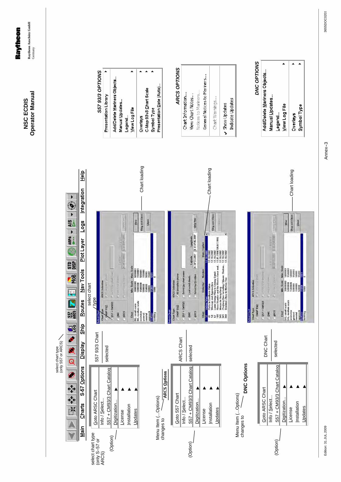
Op
erat
or
Man
ual
Ray
theo
nA
nsch
ütz
Gm
bHG
erm
any
RN
SC
EC
DIS
3655
DO
C02
01E
ditio
n:31
.JU
L.20
09A
nnex
--3
S57
93/3
OP
TIO
NS
Cha
rtlo
adin
g
sele
ctch
art
type
sele
ctch
artt
ype
(onl
yS
57or
AR
CS
)
sele
ctch
artt
ype
(onl
yS
--57
orA
RC
S)
AR
CS
OP
TIO
NS
S57
93/3
Cha
rt
sele
cted
AR
CS
Cha
rt
sele
cted
Men
uIte
m(.
..Opt
ions
)ch
ange
sto
(Opt
ion)
(Opt
ion)
Cha
rtlo
adin
g
Got
oA
RS
CC
hart
Info
/Sel
ect..
.
S57
+C
M93
/3C
hart
Cat
alog
Dig
itiza
tion.
.."
Lice
nse
"
Inst
alla
tion
"
Upd
ates
"
Got
oS
57C
hart
Info
/Sel
ect..
.
S57
+C
M93
/3C
hart
Cat
alog
Dig
itiza
tion.
.."
Lice
nse
"
Inst
alla
tion
"
Upd
ates
"
Cha
rtlo
adin
g
DN
CC
hart
sele
cted
Men
uIte
m(.
..Opt
ions
)ch
ange
sto
(Opt
ion)
DN
CO
PT
ION
S
DN
CO
pti
on
s
Got
oA
RS
CC
hart
Info
/Sel
ect..
.
S57
+C
M93
/3C
hart
Cat
alog
Dig
itiza
tion.
.."
Lice
nse
"
Inst
alla
tion
"
Upd
ates
"

Op
erat
or
Man
ual
Ray
theo
nA
nsch
ütz
Gm
bHG
erm
any
RN
SC
EC
DIS
3655
DO
C02
01E
ditio
n:03
.MA
R.2
009
Ann
ex--4
Ch
art
Info
rmat
ion
....
Vie
wC
har
tN
ote
s....
Gen
ralN
oti
ces
toM
arin
ers.
..
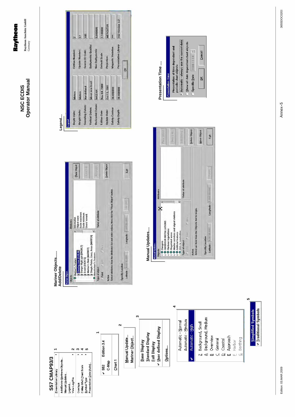
Op
erat
or
Man
ual
Ray
theo
nA
nsch
ütz
Gm
bHG
erm
any
RN
SC
EC
DIS
3655
DO
C02
01E
ditio
n:03
.MA
R.2
009
Ann
ex--5
1
3
4
5
Mar
iner
Ob
ject
s....
..A
dd
/Del
ete
Man
ual
Up
dat
es...
.
Leg
end
....
2
S57
CM
AP
93/3
1 2 3 4 5
Pre
sen
tati
on
Tim
e...
.

Op
erat
or
Man
ual
Ray
theo
nA
nsch
ütz
Gm
bHG
erm
any
RN
SC
EC
DIS
3655
DO
C02
01E
ditio
n:03
.MA
R.2
009
Ann
ex--6
S57
Lice
nse.
.IH
OS
--63
AR
CS
Lice
nse.
.
1"
2
1S
5793
/3L
icen
se..
Ch
arts
3
Got
oA
RS
CC
hart
Info
/Sel
ect..
.
S57
+C
M93
/3C
hart
Cat
alog
Dig
itiza
tion.
.."
Lice
nse
"
Inst
alla
tion
"
Upd
ates
"

Op
erat
or
Man
ual
Ray
theo
nA
nsch
ütz
Gm
bHG
erm
any
RN
SC
EC
DIS
3655
DO
C02
01E
ditio
n:03
.MA
R.2
009
Ann
ex--6
--1
2IH
OS
--63
3A
RC
SL
icen
se..
S57
Lice
nse.
.IH
OS
--63
AR
CS
Lice
nse.
.
1 2"
3""
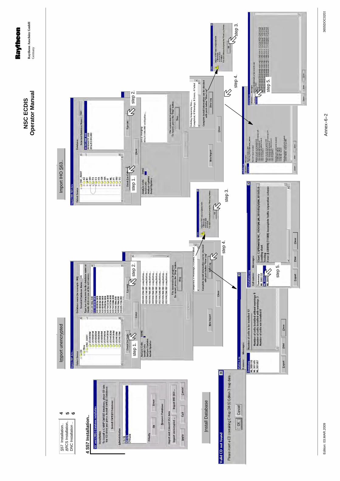
Op
erat
or
Man
ual
Ray
theo
nA
nsch
ütz
Gm
bHG
erm
any
RN
SC
EC
DIS
3655
DO
C02
01E
ditio
n:03
.MA
R.2
009
Ann
ex--6
--2
S57
Inst
alla
tion.
.A
RC
SIn
stal
latio
n..
DN
CIn
stal
latio
n..
4 5
4S
57In
stal
lati
on
..
Impo
rtun
encr
ypte
dIm
port
IHO
S63
..
Inst
allD
atab
ase
6
step
3.st
ep4.
step
4.st
ep3.
step
1.st
ep2.
step
1.st
ep2.
step
5.
step
5.
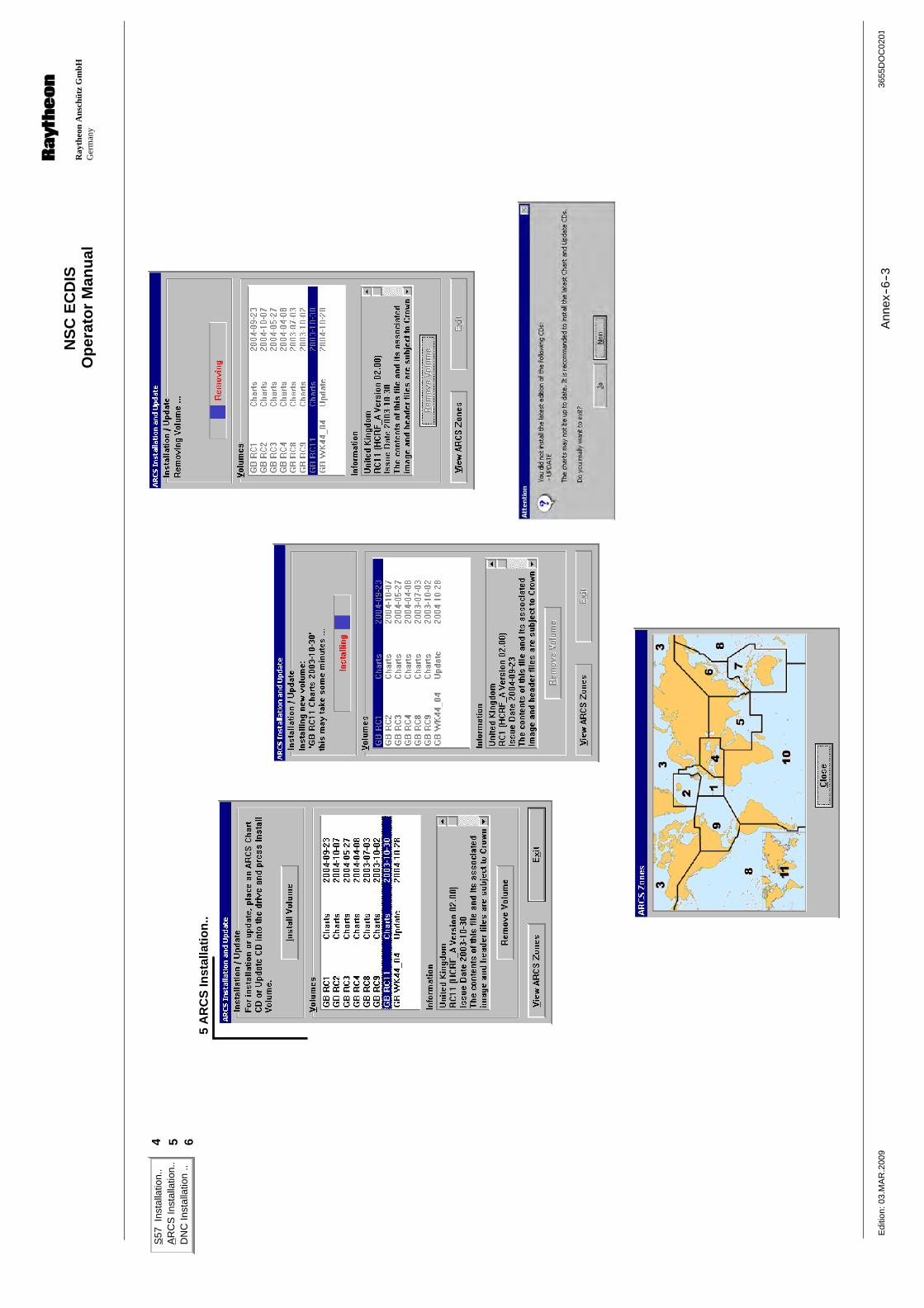
Op
erat
or
Man
ual
Ray
theo
nA
nsch
ütz
Gm
bHG
erm
any
RN
SC
EC
DIS
3655
DO
C02
01E
ditio
n:03
.MA
R.2
009
Ann
ex--6
--3
5A
RC
SIn
stal
lati
on
..
S57
Inst
alla
tion.
.A
RC
SIn
stal
latio
n..
DN
CIn
stal
latio
n..
4 5 6
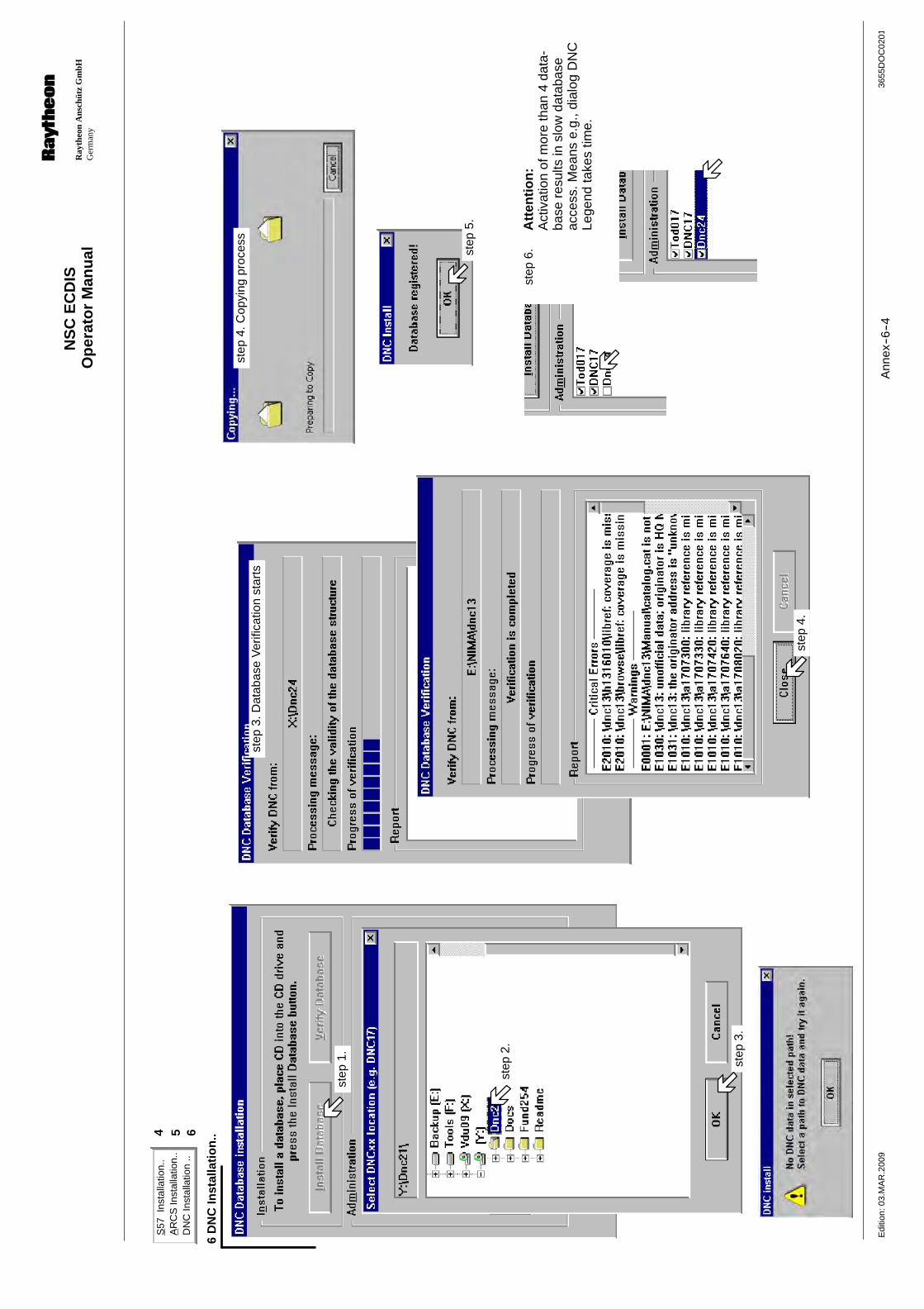
Op
erat
or
Man
ual
Ray
theo
nA
nsch
ütz
Gm
bHG
erm
any
RN
SC
EC
DIS
3655
DO
C02
01E
ditio
n:03
.MA
R.2
009
Ann
ex--6
--4
S57
Inst
alla
tion.
.A
RC
SIn
stal
latio
n..
DN
CIn
stal
latio
n..
4 5 6
6D
NC
Inst
alla
tio
n..
step
1.
step
2.
step
3.
step
4.
step
3.D
atab
ase
Ver
ifica
tion
star
tsst
ep4.
Cop
ying
proc
ess
step
5.
step
6.A
tten
tio
n:
Act
ivat
ion
ofm
ore
than
4da
ta-
base
resu
ltsin
slow
data
base
acce
ss.M
eans
e.g.
,dia
log
DN
CLe
gend
take
stim
e.
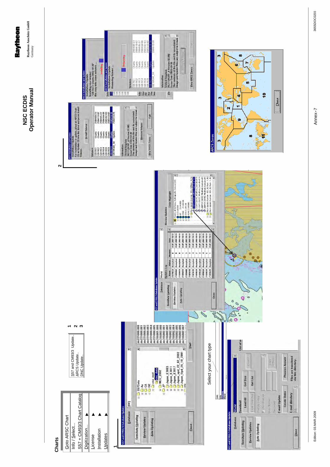
Op
erat
or
Man
ual
Ray
theo
nA
nsch
ütz
Gm
bHG
erm
any
RN
SC
EC
DIS
3655
DO
C02
01E
ditio
n:03
.MA
R.2
009
Ann
ex--7
1
Sel
ecty
our
char
ttyp
e
1 2S
57an
dC
M93
/3U
pdat
e..
AR
CS
Upd
ate.
.D
NC
Upd
ate.
.3
2C
har
ts
Got
oA
RS
CC
hart
Info
/Sel
ect..
.
S57
+C
M93
/3C
hart
Cat
alog
Dig
itiza
tion.
.."
Lice
nse
"
Inst
alla
tion
"
Upd
ates
"
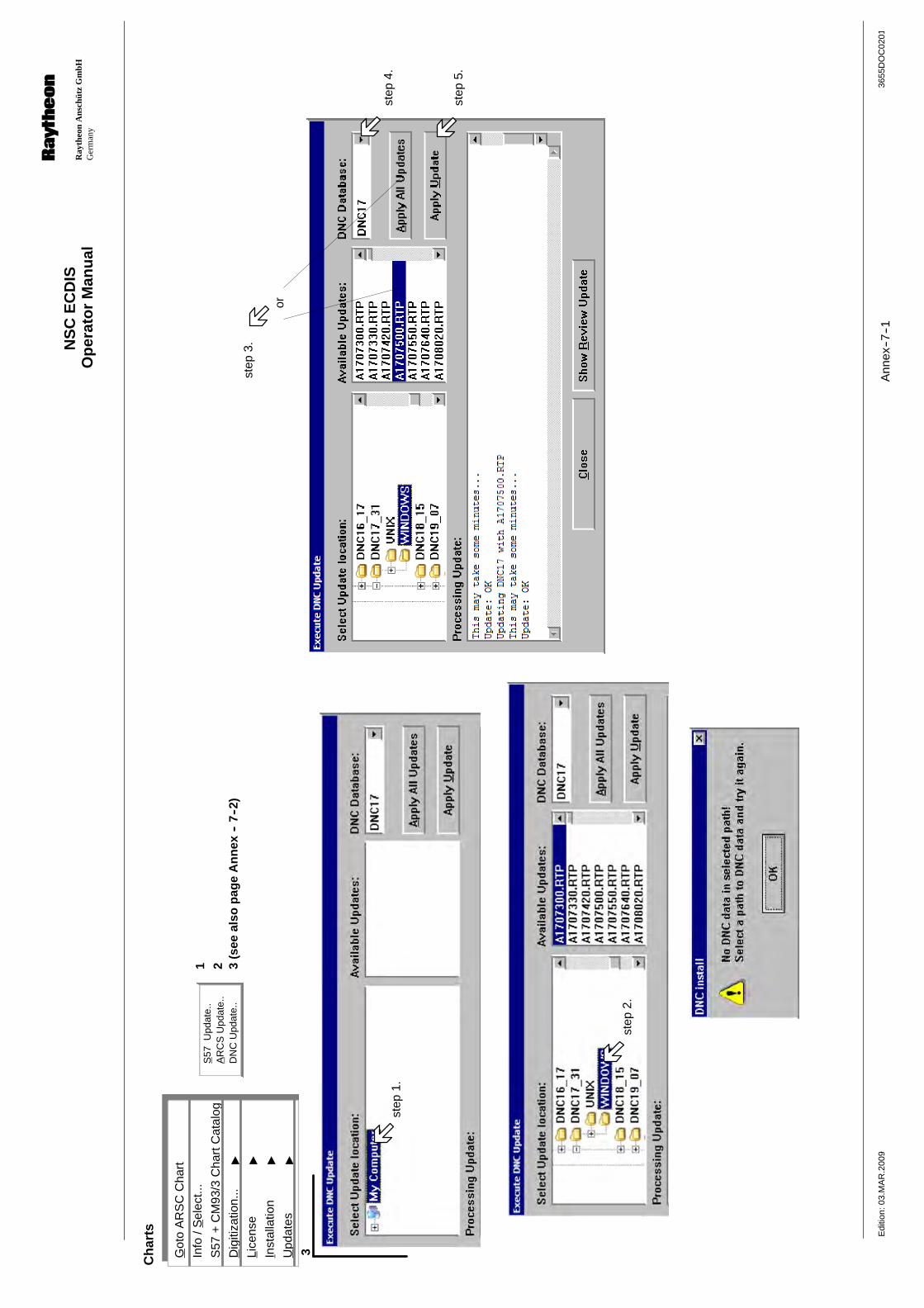
Op
erat
or
Man
ual
Ray
theo
nA
nsch
ütz
Gm
bHG
erm
any
RN
SC
EC
DIS
3655
DO
C02
01E
ditio
n:03
.MA
R.2
009
Ann
ex--7
--1
3
step
1.
step
2.
Ch
arts
step
3.
1 2S
57U
pdat
e..
AR
CS
Upd
ate.
.D
NC
Upd
ate.
.3
(see
also
pag
eA
nn
ex--
7--2
)
step
4.
step
5.
or
Got
oA
RS
CC
hart
Info
/Sel
ect..
.
S57
+C
M93
/3C
hart
Cat
alog
Dig
itiza
tion.
.."
Lice
nse
"
Inst
alla
tion
"
Upd
ates
"
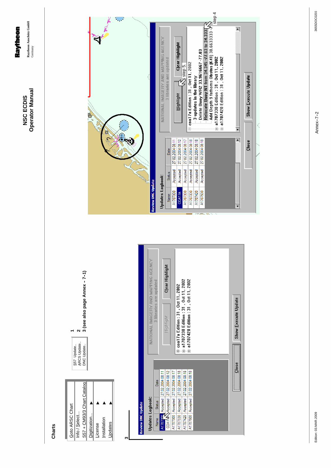
Op
erat
or
Man
ual
Ray
theo
nA
nsch
ütz
Gm
bHG
erm
any
RN
SC
EC
DIS
3655
DO
C02
01E
ditio
n:03
.MA
R.2
009
Ann
ex--7
--2
1 2S
57U
pdat
e..
AR
CS
Upd
ate.
.D
NC
Upd
ate.
.3
(see
also
pag
eA
nn
ex--
7--1
)
3Ch
arts
step
4
step
5.
Got
oA
RS
CC
hart
Info
/Sel
ect..
.
S57
+C
M93
/3C
hart
Cat
alog
Dig
itiza
tion.
.."
Lice
nse
"
Inst
alla
tion
"
Upd
ates
"
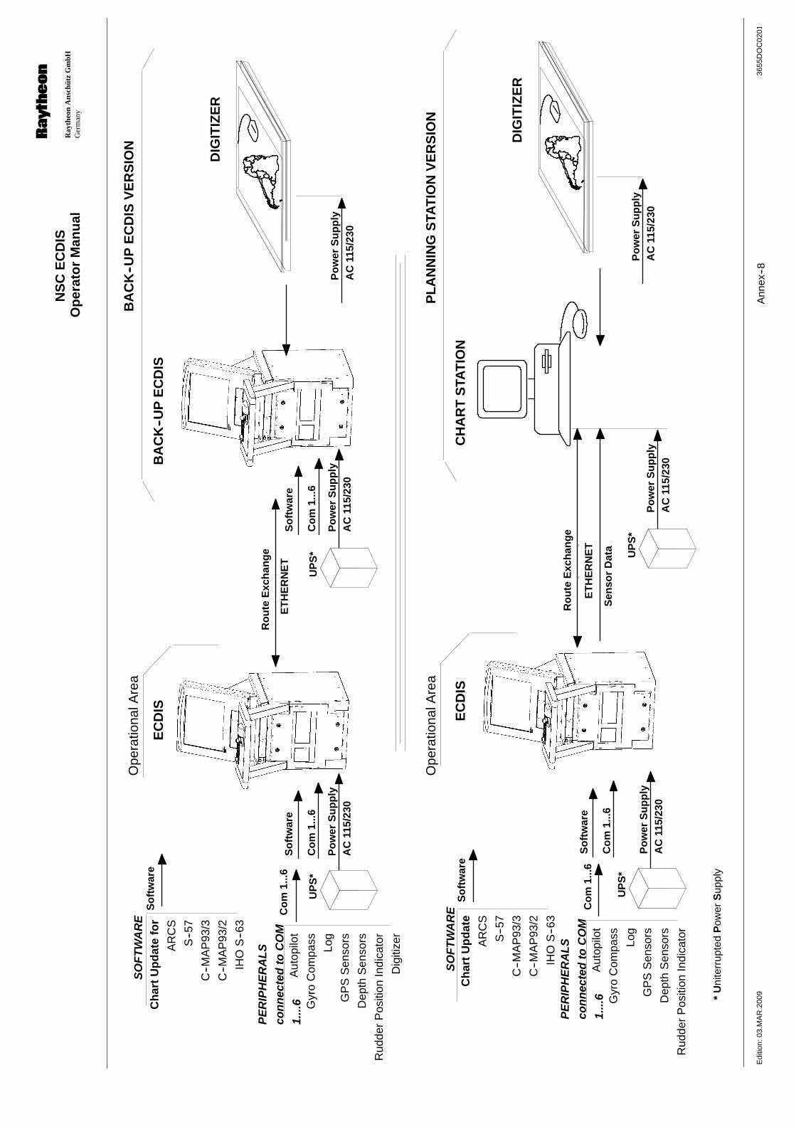
Op
erat
or
Man
ual
Ray
theo
nA
nsch
ütz
Gm
bHG
erm
any
RN
SC
EC
DIS
3655
DO
C02
01E
ditio
n:03
.MA
R.2
009
Ann
ex--8
Ch
art
Up
dat
efo
r
AR
CS
S--5
7
C--M
AP
93/3
C--M
AP
93/2
IHO
S--6
3
SO
FT
WA
RE
Aut
opilo
t
Gyr
oC
ompa
ss
Log
GP
SS
enso
rs
Dep
thS
enso
rs
Rud
der
Pos
ition
Indi
cato
r
Dig
itize
r
PE
RIP
HE
RA
LS
con
nec
ted
toC
OM
1....
6C
om
1...6
Co
m1.
..6
So
ftw
are
So
ftw
are
Po
wer
Su
pp
lyA
C11
5/23
0
UP
S*
EC
DIS
BA
CK
--UP
EC
DIS
DIG
ITIZ
ER
Co
m1.
..6
So
ftw
are
Ro
ute
Exc
han
ge
BA
CK
--UP
EC
DIS
VE
RS
ION
ET
HE
RN
ET
Po
wer
Su
pp
lyA
C11
5/23
0
UP
S*
*U
nite
rrup
ted
Pow
erS
uppl
y
Po
wer
Su
pp
lyA
C11
5/23
0
EC
DIS
CH
AR
TS
TAT
ION
DIG
ITIZ
ER
Co
m1.
..6
Co
m1.
..6
So
ftw
are
So
ftw
are
Ro
ute
Exc
han
ge
PL
AN
NIN
GS
TAT
ION
VE
RS
ION
ET
HE
RN
ET
Po
wer
Su
pp
lyA
C11
5/23
0P
ow
erS
up
ply
AC
115/
230
UP
S*
UP
S*
Po
wer
Su
pp
lyA
C11
5/23
0
Sen
sor
Dat
a
Ch
art
Up
dat
e
AR
CS
S--5
7
C--M
AP
93/3
C--M
AP
93/2
IHO
S--6
3
SO
FT
WA
RE
Aut
opilo
t
Gyr
oC
ompa
ss
Log
GP
SS
enso
rs
Dep
thS
enso
rs
Rud
der
Pos
ition
Indi
cato
r
PE
RIP
HE
RA
LS
con
nec
ted
toC
OM
1....
6
Ope
ratio
nalA
rea
Ope
ratio
nalA
rea