ˆˇ˘˜˚˛˝˙ˆ˜˘ - Hitachi...2 CS・3253 - 961 ˜˚˛˝˙ˆˇ˘ ˘ ˙ˇ ˙ ˝˘ ˇ ˙ ˇ Range...
12
1 CS・ 3253 - 961 EDR-N7 is intelligent transmitter equipped with semiconductor sensers and micro processors. EDR-N7,EDR-N7E (high accuracy type) ●EDR-N7 Range Code Measuring Span Settable Range Limits 800 H800 0.8 to 8kPa -8≦LRV≦8kPa,-8≦URV≦8kPa 8000 H8000 0.8 to 80kPa -80≦LRV≦80kPa,-80≦URV≦80kPa 40000 H40000 20 to 400kPa -400≦LRV≦400kPa,-400≦URV≦400kPa 100000 H100000 100 to 1000kPa -1000≦LRV≦1000kPa,-1000≦URV≦1000kPa ●EDR-N7E Range Code Measuring Span Settable Range Limits 800 H800 0.098 to 8kPa -8≦LRV≦8kPa,-8≦URV≦8kPa 8000 H8000 0.8 to 80kPa -80≦LRV≦80kPa,-80≦URV≦80kPa 40000 H40000 20 to 400kPa -400≦LRV≦400kPa,-400≦URV≦400kPa Note) URV is the input differential pressure to give 100% output (20mA DC) LRV is the input differential pressure to give 0% output (4mA DC) 4 to 20mA DC 11.4 to 42.0V DC 600Ω(at 24V DC power supply voltage) Power supply voltage 16.7 to 42.0V DC Load resistance 250Ωto 1.2kΩ(Refer to Fig.1 for the relation between power supply voltage and load resistance) ●EDR-N7 Range Code Accuracy 800 H800 ±0.2% ±[0.05+(0.15×3.2/X)]% X is more than 3.2kPa X is less than 3.2kPa 8000 H8000 ±0.2% ±[0.1+(0.1×8/X)]% X is more than 8kPa X is less than 8kPa 40000 H40000 ±0.2% ±[0.1+(0.1×40/X)]% X is more than 40kPa X is less than 40kPa 100000 H100000 ±0.2% ●EDR-N7E Range Code Accuracy 800 H800 ±0.2% large value between ± [0.05 + (0.15 x 1/X)]% and ± 1.96kPa X is more than 1kPa X is less than 1kPa 8000 H8000 ±0.1% ±[0.05 + (0.05×8/X)]% X is more than 8kPa X is less than 8kPa 40000 H40000 ±0.1% ±[0.05+(0.05×40/X)]% X is more than 40kPa X is less than 40kPa Note 1) Accuracy is percent value against X, and X is the largest value among absolute value of URV, LRV and measuring span. Unit is kPa. Note 2) When square root output, if zero cut is specified, for output less than 1.1% : ±(linear output accuracy×45) % for output 1.1 to 50% : ± (linear output accuracy× 50/square root output %) % for output more than 50% : same as linear output ※Using the DCR or the HART Ⓡ type communicator, it is possible to select whether output under zero cutting point equals zero, or getting zero cutting point from arbitrary straight line. if zero cut is not specified, for output less than 20%, becomes the straight line between 0-20% point. for output more than 20%, same as the above case that zero cut is specified Externally adjustable within ± 100% of measurement span. � � � � � � � � � � � � � � � � � Can select any one among burn up, burn down and without burn out. Approx. 0.4sec Adjustable from 0.2 to 102.4sec (0.1sec increment) electrically by the DCR or the HART Ⓡ communicator. Differential Pressure Transmitter C S CODE AND SPECIFICATIONS SHEET
Transcript of ˆˇ˘˜˚˛˝˙ˆ˜˘ - Hitachi...2 CS・3253 - 961 ˜˚˛˝˙ˆˇ˘ ˘ ˙ˇ ˙ ˝˘ ˇ ˙ ˇ Range...

1
CS・3253 - 961
EDR-N7 is intelligent transmitter equipped with semiconductor sensers and micro processors.
����������������������� ����� EDR-N7,EDR-N7E (high accuracy type) ��������������������������� ●EDR-N7 Range Code
Measuring Span Settable Range Limits
800 H800 0.8 to 8kPa -8≦LRV≦8kPa,-8≦URV≦8kPa
8000 H8000 0.8 to 80kPa -80≦LRV≦80kPa,-80≦URV≦80kPa
40000 H40000 20 to 400kPa -400≦LRV≦400kPa,-400≦URV≦400kPa
100000 H100000 100 to 1000kPa -1000≦LRV≦1000kPa,-1000≦URV≦1000kPa
●EDR-N7E Range Code
Measuring Span Settable Range Limits
800 H800 0.098 to 8kPa -8≦LRV≦8kPa,-8≦URV≦8kPa
8000 H8000 0.8 to 80kPa -80≦LRV≦80kPa,-80≦URV≦80kPa
40000 H40000 20 to 400kPa -400≦LRV≦400kPa,-400≦URV≦400kPa
Note)
URV is the input differential pressure to give 100% output (20mA DC)
LRV is the input differential pressure to give 0% output (4mA DC)
������� 4 to 20mA DC ������������������ 11.4 to 42.0V DC �������������������������� 600Ω(at 24V DC power supply voltage)���������������������������
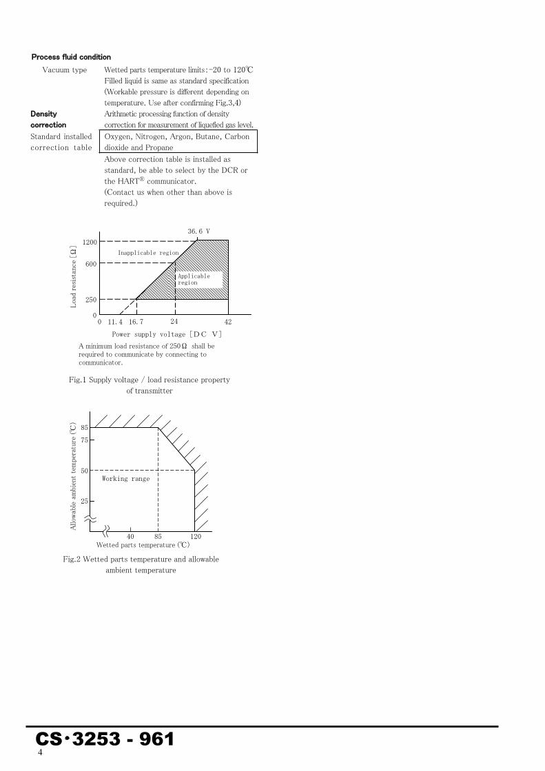
Power supply voltage 16.7 to 42.0V DC Load resistance
250Ωto 1.2kΩ(Refer to Fig.1 for the relation between power supply voltage and load resistance)
��������� ●EDR-N7 Range Code Accuracy
800 H800
±0.2% ±[0.05+(0.15×3.2/X)]%
X is more than 3.2kPaX is less than 3.2kPa
8000H8000
±0.2% ±[0.1+(0.1×8/X)]%
X is more than 8kPa X is less than 8kPa
40000H40000
±0.2% ±[0.1+(0.1×40/X)]%
X is more than 40kPaX is less than 40kPa
100000H100000 ±0.2%
●EDR-N7E Range Code Accuracy
800 H800
±0.2% large value between ± [0.05 + (0.15 x 1/X)]%and ± 1.96kPa
X is more than 1kPaX is less than 1kPa
8000
H8000±0.1% ±[0.05 + (0.05×8/X)]%
X is more than 8kPa X is less than 8kPa
40000H40000
±0.1% ±[0.05+(0.05×40/X)]%
X is more than 40kPaX is less than 40kPa
Note 1) Accuracy is percent value against X, and X is the largest value among absolute value of URV, LRV and measuring span. Unit is kPa.
Note 2) When square root output, if zero cut is specified,
for output less than 1.1% : ±(linear output accuracy×45) %for output 1.1 to 50% : ± (linear output accuracy×
50/square root output %) % for output more than 50% : same as linear output
※Using the DCR or the HARTⓇ type communicator, it is possible to select whether output under zero cutting point equals zero, or getting zero cutting point from arbitrary straight line.
if zero cut is not specified, for output less than 20%, becomes the straight line between 0-20% point. for output more than 20%, same as the above case that zero cut is specified
��������������� Externally adjustable within ± 100% of measurement span.
���������� ���� ��� Can select any one among burn up, burn down and without burn out.
���������� Approx. 0.4sec ����������������������������������������������
Adjustable from 0.2 to 102.4sec (0.1sec increment) electrically by the DCR or the HARTⓇ communicator.
Differential Pressure Transmitter ����������������C S
CODE AND SPECIFICATIONS SHEET

2
CS・3253 - 961
���������������������������� Range Code Time Constant
of Sensor Body (at 25℃)800,H800 Approx. 0.7sec
8000,H8000 Approx. 0.2sec 40000,H40000 Approx. 0.1sec
100000,H100000 Approx. 0.1sec ・ Transmitter time constant equals total sum of
the above time constant of sensor body, damping setting time constant (amplifier time constant) and dead time.
・ When pressure pulsation is expected, fixed electrical damper (about 1sec) shall be specified, at the same time we recommend that inner diameter φ1 capillary tube (more than 1m length) is inserted.
���������������������������
-40 to 85℃
����������������� ��������
5 to 100%RH
�������� �������������������� Ambient temperature limits
-20 to 85℃ (see Fig.2) (-10 to 60℃ for range code 100000)
Wetted parts temperature limits -20 to 120℃
(-10 to 100℃ for range code 100000) ���� ����������������
Range Code Working pressure limits 800,H800 5MPa
8000,H8000 15MPa 40000,H40000 15MPa
100000,H100000 10MPa Note) When used under negative pressure,
refer to Fig.3, 4 ��������������� Less than 29.4m/s2 continuous vibration �������������������(at -20 to 60℃) ●EDR-N7 Range Code Temperature Effect
800 H800
Zero shift
Overall shift
±[0.05+(0.45×T/30)]% ±[0.05+(0.25+0.2×3.2/X)×T/30]% ±[0.05+(0.65×T/30)]% ±[0.05+(0.35+0.3×3.2/X)×T/30]%
X is more than 3.2kPa X is less than 3.2kPa
X is more than 3.2kPaX is less than 3.2kPa
8000 H8000
Zero shift
Overall shift
±[0.05+(0.3×T/50)]% ±[0.05+(0.15+0.15×32/X)×T/50]% ±[0.05+(0.55×T/50)]% ±[0.05+(0.4+0.15×32/X)×T/50]%
X is more than 32kPaX is less than 32kPa
X is more than 32kPaX is less than 32kPa
40000 H40000
Zero shift
Overall shift
±[0.05+(0.3×T/50)]% ±[0.05+(0.15+0.15×160/X)×T/50]% ±[0.05+(0.55×T/50)]% ±[0.05+(0.4+0.15×160/X)×T/50]%
X is more than 160kPaX is less than 160kPa
X is more than 160kPaX is less than 160kPa
100000 H100000
Zero shift
Overall shift
±[0.05+(0.3×T/50)]% ±[0.05+(0.15+0.15×400/X)×T/50]% ±[0.05+(0.55×T/50)]% ±[0.05+(0.4+0.15×400/X)×T/50]%
X is more than 400kPa X is less than 400kPa
X is more than 400kPaX is less than 400kPa
●EDR-N7E Range Code Temperature Effect
800H800
Zero shift
Overall shift
±[0.05+(0.45×T/50)]% ±[0.05+(0.25+0.2×3.2/X)×T/50]% ±[0.05+(0.75×T/50)]% ±[0.05+(0.45+0.3×3.2/X)×T/50]%
X is more than 3.2kPa X is less than 3.2kPa
X is more than 3.2kPaX is less than 3.2kPa
8000H8000
Zero shift
Overall shift
±[0.05+(0.2×T/50)]% ±[0.05+(0.15+0.05×32/X)×T/50]% ±[0.05+(0.45×T/50)]% ±[0.05+(0.4+0.05×32/X)×T/50]%
X is more than 32kPaX is less than 32kPa
X is more than 32kPaX is less than 32kPa
40000H40000
Zero shift
Overall shift
±[0.05+(0.2×T/50)]% ±[0.05+(0.15+0.05×160/X)×T/50]% ±[0.05+(0.45×T/50)]% ±[0.05+(0.4+0.05×160/X)×T/50]%
X is more than 160kPaX is less than 160kPa
X is more than 160kPaX is less than 160kPa
Note) Temperature effect is percent value against X, X is the largest value among absolute value of URV,LRVand measuring span. Unit is kPa. T is temperature variation width(℃).
����������������������(at 25℃) ●EDR-N7 Range Code Static Pressure Effect 800
H800 Zero shift ±[0.05+(0.25×8/X×P/3)]% X is less than 8kPa
8000H8000
Zero shift
Overall shift
±[0.05+(0.1×P/10)]% ±[0.05+(0.1×40/X)×P/10]% ±[0.05+(1.95+0.1×80/X)×P/10]%
X is more than 40kPa X is less than 40kPa
40000H40000
Zero shift
Overall shift
±[0.05+(0.1×P/10)]% ±[0.05+(0.1×200/X)×P/10]% ±[0.05+(1.45+0.1×400/X)×P/10]%
X is more than 200kPaX is less than 200kPa
100000H100000
Zero shift
Overall shift
±[0.05+(0.1×P/10)]% ±[0.05+(0.1×500/X)×P/10]% ±[0.05+(1.45+0.1×1000/X)×P/10]%
X is more than 500kPa X is less than 500kPa
●EDR-N7E Range Code Static Pressure Effect 800
H800 Zero shift ±[0.05+(0.1×8/X×P/5)]% X is less than 8kPa
8000H8000
Zero shift
Overall shift
±[0.05+(0.05×P/10)]% ±[0.05+(0.05×40/X)×P/10]% ±[0.05+(0.3+0.1×80/X)×P/10]%
X is more than 40kPa X is less than 40kPa
40000H40000
Zero shift
Overall shift
±[0.05+(0.05×P/10)]% ±[0.05+(0.05×200/X)×P/10]% ±[0.05+(0.3+0.1×400/X)×P/10]%
X is more than 200kPaX is less than 200kPa
Note) Static pressure effect is percent value against X, X is the largest value among absolute value of URV, LRV and measuring span. Unit is kPa. P is static pressure value, unit MPa.
�������������������(Zero shift)
±0.5% (at maximum working pressure application)(at maximum span)
��������� Diaphragm Hastelloy C
(Diaphragm material shall be selected considering corrosion resistance, hydrogen transmission, etc.)
Wetted parts other than diaphragm
SUS316
Amplifier case Aluminium alloy Mounting plate SPCC (acid resistant coating) U bolt SUS304

3
CS・3253 - 961
������ ������ Silicone oil ������������������ Top connection Rc1/4 without oval flange ��������������������� G1/2 ����� �������� With output check terminal
(output voltage 40 to 200mV DC) �������������� Degree of protection JIS C 0920 IP67 ����� �������� Built-in transmitter
Surge capacity : 1,000A (8/20μsec) Impulse test voltage :15,000V (1.2/50μsec)
������ Light gray amplifier case (acid resistant coating)������ Approx. 3.3kg ������������ On 2-inch pipe with U bolt. ����������� 2-inch pipe mounting bracket and U-bolt.
Zero adjustment magnet. ������������������������ ��������������������� HARTⓇ protocol �������� ����������� (Absolute pressure) Output method Communication by the DCR or the HARTⓇ
communicator and display by built-in indicator. Alternate display of differential pressure and pressure, arbitrary scale setting of pressure (-1,750 to 1,750 range) are available by the DCR or the HARTⓇ communicator. Digital indicator distinguishes pressure from differential pressure displaying “P” behind numerical value. And analog output [1 to 5V] is possible by using EDB500M type exclusive distributor.
Measuring span 0.5 to 5MPa abs. Accuracy ±0.2%
±0.2×(1/X)% X is more than 1MPaX is less than 1MPa
Temperature effect Zero shift ±[0.05+(1.0×T/50)]%
±[0.05+(0.5+0.5×2/X)×T/50]% X is more than 2MPa X is less than 2MPa
Overall shift ±[0.05+(2.5×T/50)]% ±[0.05+(2.0+0.5×2/X)×T/50]%
X is more than 2MPa X Is less than 2MPa
Note)Accuracy and temperature effect are percent value against X, X is the largest value among absolute value of URV, LRV and measuring span. Unit is MPa. T is temperature variation width. (℃).
��������� Flameproof Exdo II CT4 Exdo II CT4X
TIIS Ex explosion proof type
Note) X is for operating condition (as below) With meter : Abnormality code is
displayed on meter to alert winking, so it is no need to build external alarm display system.
Without meter : it is necessary to build external alarm display system, output exceeds 21mA
Ambient temperature limits : -20 to 55℃ Wetted parts temperature limits: -20 to 100℃
Electrical connection X-RCAC type pressure resistant packing fixture must be used for using pressure resistant oil filled explosion proof type products. (also applicable to use SXBM-16B made by Shimada Electric Co., Ltd.)
FM explosion proof type
Explosion proof CLI,DIV 1,GPS B,C&D Dust-ignition proof CLⅡ/Ⅲ,GPS E,F&G Temperature Code T4 NEMA 4X Ambient temperature limits : -40 to 60℃ Wetted parts temperature limits: -40 to 120℃
��������� Digital indicator 4.5 figures display (0 to 100% scale standard)
(Can set to arbitrary scale within the range of -17,500 to 17,500) Scale plates various units to be sticked are supplied.
Diaphragm Wetted Parts SUS316L SUS316 SUS316L SUS316L
Hastelloy C SUS316L Hastelloy C Hastelloy C Hastelloy C Hard PVC Tantalum SUS316 Tantalum SUS316L Tantalum Tantalum Tantalum Hard PVC
SUS316L (with gold plate) SUS316 ※ Material shall be selected considering corrosion
resistance. In case hydrogen is present in measuring fluid, it is possible hydrogen transmission can be generated through diaphragm. If corrosion resistance is not so important, we recommend SUS316L or SUS3l6 with gold plating because hydrogen transmission value of these material is relatively low. (But it is difficult to prevent hydrogen transmission completely even if diaphragm of SUS316L with gold plating is applied).
������ ����� ���������
Note) Process connection, working pressure limits and ambient temperature limits are shown in the following Table.
Wetted Parts Material
Process Connection
Working pressure limits
Ambient Temperature limits
Hastelloy C Tantalum
Half of standard product
Same as standard product
Hard PVC
Rc1/4 Take out
from the side 1MPa -10 to 60℃ ������ ������
Fluorine oil Wetted parts temperature limits:-20 to 120℃(See Fig. 5 for negative pressure) Specify also no-oil finish together for oxygen measurement
Silicone oil for sanitary use
Wetted parts temperature limits:-20 to 120℃(See Fig. 6 for negative pressure)
������ ����� ������ No oil finish or no-oil and no water finish ������� ���������� (with ovel flange)
Rc1/2, Rc1/4, 1/2NPT, 1/4NPT, 15A socket welding (socket screw-in type)
������� ������� Metal fittings for renewal of old type Hitachi transmitter are supplied
����� ������ To be attached to the sensor body (Steam temperature shall be set to get liquid contact temperature less than 120 ℃. But less than 100℃ for explosion proof type)
����� ���� ���� Thermal insulation type
4
CS・3253 - 961
����������������������� Vacuum type Wetted parts temperature limits:-20 to 120℃
Filled liquid is same as standard specification (Workable pressure is different depending on temperature. Use after confirming Fig.3,4)
�������������������
Arithmetic processing function of density correction for measurement of liquefied gas level.
Standard installed correction table
Oxygen, Nitrogen, Argon, Butane, Carbon dioxide and Propane
Above correction table is installed as standard, be able to select by the DCR or the HARTⓇ communicator. (Contact us when other than above is required.)
8575
50
25
40 85 120
Allow
able
ambie
nt tem
perat
ure (℃
)
Working range
A minimum load resistance of 250Ω shall be required to communicate by connecting to communicator.
Fig.1 Supply voltage / load resistance property of transmitter
00250
600
1200
11.4 16.7
Load
resis
tance
[Ω]
24 42Power supply voltage[DC V]
Applicable region
Inapplicable region
36.6 V
Fig.2 Wetted parts temperature and allowable ambient temperature
Wetted parts temperature (℃)

5
CS・3253 - 961
Fig.7 Alternate display of differential
pressure and pressure
Pressure display(0.00~5.00MPa abs.)
Differential pressure display (0.00~125.00kPa)
Fig.3 Working pressure and process fluid temperature(Specification for standard or vacuum type)
Fig.4 Working pressure and process fluid temperature(Range code : 100000)
図 6 使用圧力と接液温度 (封入液:サニタリ用シリコンオイル)
Worki
ng pr
essure
Minimum working temperature Maximum working temperature
Atmosphericpressure
Process fluid temperature (℃)
Inapplicable region
Applicable region for vacuum specification
Applicable region for standard specification
Worki
ng pr
essure
Minimum working temperature Maximum working temperature
Atmosphericpressure
Process fluid temperature (℃)
Inapplicable region
Applicable region for vacuum specification
Applicable region for standard specification
Minimum working temperature Maximum working temperature
Applicable region
Inapplicable region
Worki
ng pr
essure
Atmosphericpressure
Process fluid temperature (℃) Fig.5 Working pressure and process fluid temperature
(Filled liquid : Fluorine oil)
Minimum working temperature Maximum working temperature
Applicable region
Inapplicable region
Worki
ng pr
essure
Atmosphericpressure
Process fluid temperature (℃) Fig.6 Working pressure and process fluid temperature
(Filled liquid : Silicone oil for sanitary use)
6
CS・3253 - 961
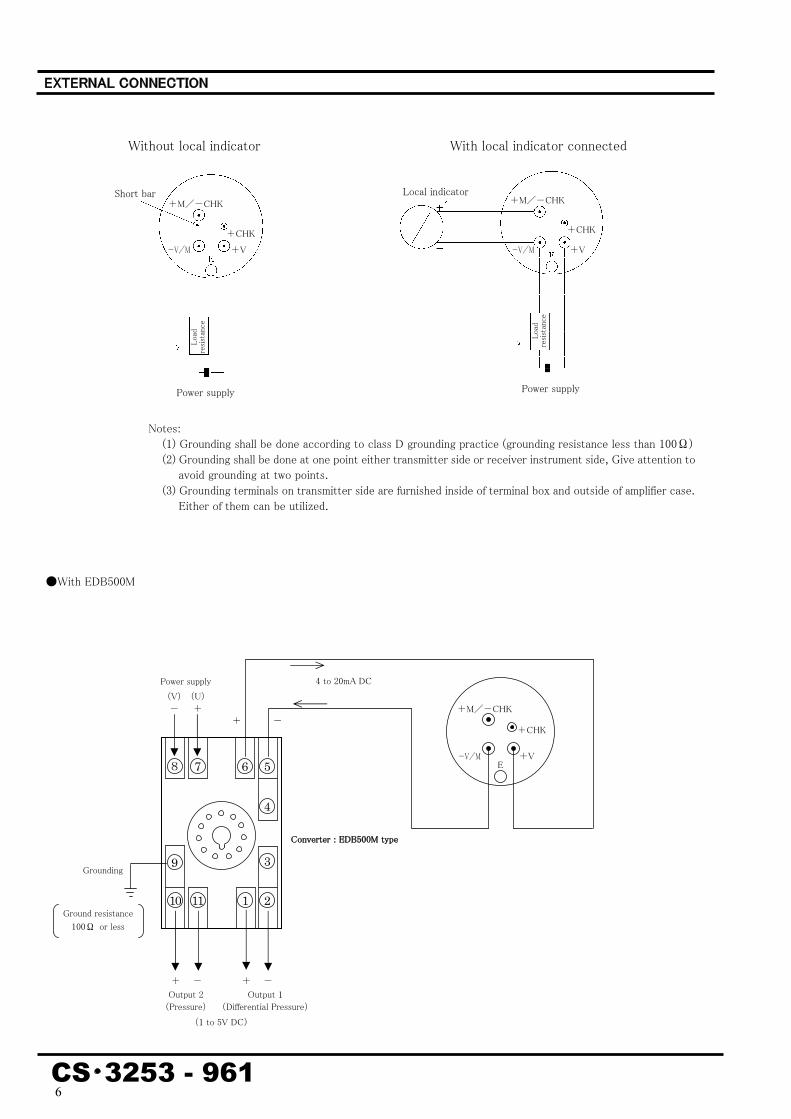
�������������������
Notes: (1) Grounding shall be done according to class D grounding practice (grounding resistance less than 100Ω) (2) Grounding shall be done at one point either transmitter side or receiver instrument side, Give attention to
avoid grounding at two points. (3) Grounding terminals on transmitter side are furnished inside of terminal box and outside of amplifier case.
Either of them can be utilized.
With local indicator connected Without local indicator
●With EDB500M
8
Grounding
Ground resistance 100Ω or less
������������������������
Output 2 (Pressure)
+ -
Power supply (U) +
(V) -
4 to 20mA DC
-+
Output 1 (Differential Pressure)
7 6 5
4
3
2111 10
9
(1 to 5V DC)
Short bar Local indicatorLo
ad
resist
ance
Load
res
istan
ce
Power supply Power supply
+M/-CHK +M/-CHK
-V/M
E
+CHK
+V-V/M
-V/M +V +V
+M/-CHK
+ -
+CHK +CHK

7
CS・3253 - 961
���������������������
●Process connections code PV4
●With oval flange (top connection) High pressure side process connection
Low pressure side process connectionOval flange (optional)
AmplifierGround terminal
Indicator(optional)
Special fastening for flameproof type
Electrical connection (stop plug) Electrical connection
G1/2Sensor body
Use 2-inch pipe
High pressure side flange
Low pressure side flange
AmplifierGround terminal
Indicator(optional)
Electrical connection (stop plug) Electrical connection
G1/2
Sensor body
Vent plug
Process connection (Rc1/4)
Use 2-inch pipeMaterial code A B
HC, TA 90 142HCPVC,TAPVC 104 172
5 124
25
30 6215
2.5
143
189
32
54
2662
3115
2.5
33
25
5 124 136
182 51
Special fastening for flameproof type
φ94
φ94
51
8
CS・3253 - 961
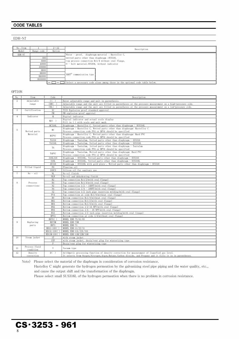
No.,Item 1 2~12 Model Range code Option Description
EDR-N7 Water - proof, diaphragm material ; Hastelloy C, 800 wetted parts other than diaphragm ;SUS316, 8000 top process connection Rc1/4 without oval flange, 40000 U - bolt material,SUS304, without indicator 100000 H800 H8000 H40000 H100000
HARTⓇ communication type
Select a necessary code alone among those in the optional code table below.
OPTION No. Item Code Description 2 Adjustable C( ) Enter adjustable range and unit in parenthesis. range CDH( ) Adjustable range and the unit are filled in parentheses at the pressure measurement on a high—pressure side. CDL( ) Adjustable range and the unit are filled in parentheses at the pressure measurement on a low—pressure side. 3 Certification XC TIIS Explosion proof standard approval FM FM explosion proof approval 4 Indicator M Digital indicator. MJ( ) Digital indicator and actual scale display
Fill in ( ) with scale and unit mark HC316L Diaphragm : Hastelloy C. Vetted parts other than diaphragm : SUS316L 5 HC Diaphragm : Hastelloy C, Wetted parts other than diaphragm: Hastelloy C
Process connection code PV4 or BPV4 should be specified
Wetted parts Material HCPVC Diaphragm : Hastelloy C. Wetted parts other than diaphragm: Hard PVC
Process connection code PV4 or BPV4 should be specified TA316 Diaphragm : Tantalum, Vetted parts other than diaphragm : SUS316 TA316L Diaphragm : Tantalum, Vetted parts other then diaphragm : SUS316L TA Diaphragm : Tantalum, lotted parts other than diaphragm : Tantalum
Process connection code PV4 or BPV4 should be specified TAPVC Diaphragm : Tantalum, Wetted parts other than diaphragm: Hard PVC
Process connection code PV4 or BPV4 should be specified 316L316 Diaphragm : SUS316L, Vetted parts other than diaphragm : SUS316 316L Diaphragm : SUS316L, Vetted parts other than diaphragm : SUS316L AU316 Diaphragm : SUS316L with gold plate , Wetted parts other than diaphragm : SUS316 6 Filled liquid FO Fluorine oil 100CS Silicon oil for sanitary use 7 No - oil NL No-oil finish NLW No-oil and dehydrating finish R2 Top connection Rc1/2(with oval flange) 8 Process R4 Top connection Rcl/4(with oval flange) connections N2 Top connection 1/2 - 14NPT(with oval flange) N4 Top connection 1/4 - 18NPT(with oval flange) S2 Top connection 1/2 inch pipe insertion welding(with oval flange) PV4 Top connection at side Rc1/4(without oval flange) B0 Bottom connection Rc1/4(without oval flange) BR2 Bottom connection Rc1/2(with oval flange) BR4 Bottom connection Rc1/4(with oval flange) BN2 Bottom connection 1/2-14 NPT(with oval flange) BN4 Bottom connection 1/4 - 18 NPT(with oval flange) BS2 Bottom connection 1/2 inch pipe insertion welding(with oval linage) BPV4 Bottom connection at side 1/4(without oval flange) RD78( ) MODEL EDR-75/81/85 9 Replacing RD75M MODEL EDR-75M parts RD71 MODEL EDR-71 RD11・100( ) MODEL EDR-11/22/31 RD11L・100( ) MODEL EDR-11L/22L/31L RD11M・100( ) MODEL EDR-11M/22M/31M 10 Steam jacket ST with steam jacket STP with steam jacket, drain/vent plug for winterizing type P Drain/vent plug for winterizing type 11 Process fluid
condition V Vacuum type 12 Density D( ) Arithmetic processing function of density correction for measurement of liquefied gas level. correction It selects from Oxygen,Nitrogen,Argon,Butane,Carbon dioxide, and Propane and it fills it in in parentheses.
Note) Please select the material of the diaphragm in consideration of corrosion resistance. Hastelloy C might generate the hydrogen permeation by the galvanizing steel pipe piping and the water quality, etc., and cause the output shift and the transformation of the diaphragm. Please select small SUS316L of the hydrogen permeation when there is no problem in corrosion resistance.
�����������
EDR-N7

9
CS・3253 - 961
No., Item 1 2~12 Model Renge code Option Description EDR-N7E Water - proof, diaphragm material ; Hastelloy C, 800 wetted parts other than diaphragm ;SUS316, top process connection Rc1/4 without oval flange, 8000 U - bolt material,SUS304, without indicator 40000 H800 H8000 H40000
HARTⓇ communication type
Select a necessary code alone among those in the optional code table below.
OPTION No. Item Code Description 2 Adjustable C( ) Enter adjustable range and unit in parenthesis. range CDH( ) Adjustable range and the unit are filled in parentheses at the pressure measurement on a high-pressure side. CDL( ) Adjustable range and the unit are filled in parentheses at the pressure measurement on a low-pressure side. 3 Certification XC TIIS Explosion proof standard approval FM FM explosionproof 4 Indicator M Digital indicator MJ( ) Digital indicator and actual scale display
Fill in ( ) with scale and unit mark 5 Wetted parts 316L316 Diaphragm : SUS316L Wetted parts other than diaphragm : SUS316 Material 316L Diaphragm : SUS316L Wetted parts other than diaphragm : SUS316L HC316L Diaphragm : Hastelloy C Wetted parts other than diaphragm : SUS316L AU316 Diaphragm : SUS316L with gold plate, Wetted parts other tnan diaphragm : SUS316 6 Filled liquid FO Fluorine oil 100CS Silicon oil for sanitary use 7 No-oil NL No-oil finish NLW No-oil and dehydrating finish R2 Top connection Rc1/2(with oval flange) 8 Process R4 Top connection Rcl/4(with oval flange) connections N2 Top connection 1/2 - 14NPT(with oval flange) N4 Top connection I/4 - 18NPT(with oval flange) S2 Top connection 1/2 inch pipe insertion welding(with oval flange) B0 Bottom connection Rc1/4(without oval flange) BR2 Bottom connection Rcl/2(with oval flange) BR4 Bottom connection Rcl/4(with oval flange) BN2 Bottom connection 1/2-14 NPT(with oval flange) BN4 Bottom connection 1/4 - 18 NPT(with oval flange) BS2 Bottom connection 1/2 inch pipe insertion welding(with oval linage) RD78( ) MODEL EDR-75/81/85 9 Replacing RD75M MODEL EDR-75M parts RD71 MODEL EDR-71 RD11・100( ) MODEL EDR-11/22/31 RD11L・100( ) MODEL EDR-11L/22L/31L RD11M・100( ) MODEL EDR-11M/22M/31M 10 Steam ST with steam jacket jacket STP with steam jacket,drain/vent plug for winterizing type P Drain/vent plug for winterizing type 11 Process fluid
condition V Vacuum type 12 Density D( ) Arithmetic processing function of density correction for measurement of liquefied gas level. correction It selects from Oxygen,Nitrogen,Argon,Butane,Carbon dioxide, and Propane and it fills it in in parentheses.
Note) Please select the material of the diaphragm in consideration of corrosion resistance. Hastelloy C might generate the hydrogen permeation by the galvanizing steel pipe piping and the water quality, etc., and cause the output shift and the transformation of the diaphragm. Please select small SUS316L of the hydrogen permeation when there is no problem in corrosion resistance.
EDR-N7E

10
CS・3253 - 961

11
CS・3253 - 961

12
CS・3253 - 961
●HARTⓇ is a registered trademark of the HART Communication Foundation. ●Be sure to read the User’s Manual to ensure correct, safe use.●Some specifications and design are subject to change with or without notice for improvement of quality and performance.
HCS-E2151
Hitachi High-Tech Solutions Corporationhttp://www.hitachi-hitec-solutions.com24-14, Nishi-Shimbashi 1-chome, Minato-ku, Tokyo 105-8418, JAPANTel: +81-3-3504-7311 Fax: +81-3-3504-7363
Hitachi High-Tech Control Systems Corporationhttp://www.hitachi-hitec-hcs.com500, Miyu-cho, Mito-shi, Ibaraki-ken, 319-0316, JAPANTel: +81-29-257-5100 Fax: +81-29-257-5120