(ohne Altea XL, -Freetrack und – 4 Freetrack ) SEAT Leon ...erstellt am: 05.09.11 E4-WM4-Y646A00_4...
28
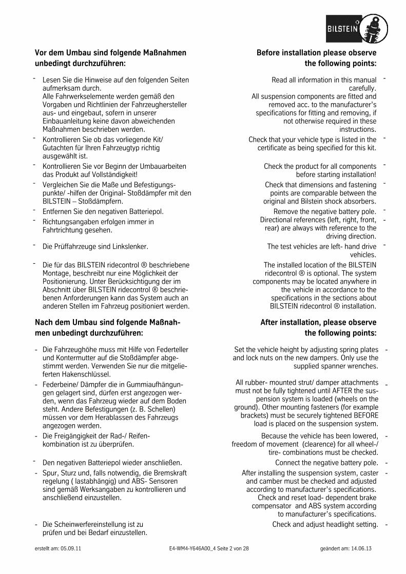
erstellt am: 05.09.11 E4-WM4-Y646A00_4 Seite 1 von 28 geändert am: 14.06.13 Inhalt : - Teile- Gutachten BILSTEIN ridecontrol ® - AUDI A3/ S3/ RS3 incl. Sportback, quattro und Cabrio - SEAT Altea (ohne Altea XL, -Freetrack und – 4 Freetrack ) - SEAT Leon - SEAT Toledo - SKODA Oktavia - VW Golf V + VI - VW Golf Plus - VW Golf V + VI 4- motion - VW Golf V + VI Variant - VW Golf V + VI Cabrio - VW Jetta - VW Scirocco - Einbauanleitungen Contents: - certificate BILSTEIN ridecontrol ® for: AUDI A3/ S3/ RS3 incl. Sportback, Quattro and convertible - SEAT Altea PSS10 (without Altea XL, -Freetrack und – 4 Freetrack ) - Seat Leon - SEAT Toledo - SKODA Oktavia - VW Golf V + VI - VW Golf Plus - VW Golf V + VI 4- motion - VW Golf V + VI station wagon - VW Golf V + VI convertible - VW Jetta - VW Scirocco - mounting instruction -
Transcript of (ohne Altea XL, -Freetrack und – 4 Freetrack ) SEAT Leon ...erstellt am: 05.09.11 E4-WM4-Y646A00_4...

erstellt am: 05.09.11 E4-WM4-Y646A00_4 Seite 1 von 28 geändert am: 14.06.13
Inhalt :
- Teile- Gutachten BILSTEIN ridecontrol ®
- AUDI A3/ S3/ RS3 incl. Sportback, quattro und Cabrio - SEAT Altea (ohne Altea XL, -Freetrack und – 4 Freetrack ) - SEAT Leon - SEAT Toledo - SKODA Oktavia - VW Golf V + VI - VW Golf Plus - VW Golf V + VI 4- motion - VW Golf V + VI Variant - VW Golf V + VI Cabrio - VW Jetta - VW Scirocco
- Einbauanleitungen
Contents:
- certificate BILSTEIN ridecontrol ® for:
AUDI A3/ S3/ RS3 incl. Sportback, Quattro and convertible - SEAT Altea PSS10 (without Altea XL, -Freetrack und – 4 Freetrack ) -
Seat Leon - SEAT Toledo -
SKODA Oktavia - VW Golf V + VI -
VW Golf Plus - VW Golf V + VI 4- motion -
VW Golf V + VI station wagon - VW Golf V + VI convertible -
VW Jetta - VW Scirocco -
mounting instruction -
erstellt am: 05.09.11 E4-WM4-Y646A00_4 Seite 2 von 28 geändert am: 14.06.13
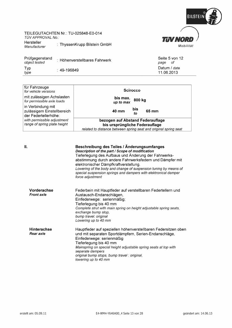
Vor dem Umbau sind folgende Maßnahmen unbedingt durchzuführen:
Before installation please observe the following points:
- Lesen Sie die Hinweise auf den folgenden Seiten aufmerksam durch. Alle Fahrwerkselemente werden gemäß den Vorgaben und Richtlinien der Fahrzeughersteller aus- und eingebaut, sofern in unserer Einbauanleitung keine davon abweichenden Maßnahmen beschrieben werden.
Read all information in this manual carefully.
All suspension components are fitted and removed acc. to the manufacturer’s
specifications for fitting and removing, if not otherwise required in these
instructions.
-
- Kontrollieren Sie ob das vorliegende Kit/ Gutachten für Ihren Fahrzeugtyp richtig ausgewählt ist.
Check that your vehicle type is listed in the certificate as being specified for this kit.
-
- Kontrollieren Sie vor Beginn der Umbauarbeiten das Produkt auf Vollständigkeit!
Check the product for all components before starting installation!
-
- Vergleichen Sie die Maße und Befestigungs-punkte/ -hilfen der Original- Stoßdämpfer mit den BILSTEIN – Stoßdämpfern.
Check that dimensions and fastening points are comparable between the
original and Bilstein shock absorbers.
-
- Entfernen Sie den negativen Batteriepol. Remove the negative battery pole. - - Richtungsangaben erfolgen immer in
Fahrtrichtung gesehen. Directional references (left, right, front,
rear) are always with reference to the driving direction.
-
- Die Prüffahrzeuge sind Linkslenker. The test vehicles are left- hand drive vehicles.
-
- Die für das BILSTEIN ridecontrol ® beschriebene Montage, beschreibt nur eine Möglichkeit der Positionierung. Unter Berücksichtigung der im Abschnitt über BILSTEIN ridecontrol ® beschrie-benen Anforderungen kann das System auch an anderen Stellen im Fahrzeug positioniert werden.
The installed location of the BILSTEIN ridecontrol ® is optional. The system
components may be located anywhere in the vehicle in accordance to the
specifications in the sections about BILSTEIN ridecontrol ® installation.
Nach dem Umbau sind folgende Maßnah-men unbedingt durchzuführen:
After installation, please observe the following points:
- Die Fahrzeughöhe muss mit Hilfe von Federteller und Kontermutter auf die Stoßdämpfer abge-stimmt werden. Verwenden Sie nur die mitgelie-ferten Hakenschlüssel.
Set the vehicle height by adjusting spring plates and lock nuts on the new dampers. Only use the
supplied spanner wrenches.
-
- Federbeine/ Dämpfer die in Gummiaufhängun-gen gelagert sind, dürfen erst angezogen wer-den, wenn das Fahrzeug wieder auf dem Boden steht. Andere Befestigungen (z. B. Schellen) müssen vor dem Herablassen des Fahrzeugs angezogen werden.
All rubber- mounted strut/ damper attachments must not be fully tightened until AFTER the sus-
pension system is loaded (wheels on the ground). Other mounting fasteners (for example
brackets) must be securely tightened BEFORE load is placed on the suspension system.
-
- Die Freigängigkeit der Rad-/ Reifen- kombination ist zu überprüfen.
Because the vehicle has been lowered, freedom of movement (clearence) for all wheel-/
tire- combinations must be checked.
-
- Den negativen Batteriepol wieder anschließen. Connect the negative battery pole. - - Spur, Sturz und, falls notwendig, die Bremskraft
regelung ( lastabhängig) und ABS- Sensoren sind gemäß Werksangaben zu kontrollieren und anschließend einzustellen.
After installing the suspension system, caster and camber must be checked and adjusted according to manufacturer’s specifications.
Check and reset load- dependent brake compensator and ABS system according
to manufacturer’s specifications.
-
- Die Scheinwerfereinstellung ist zu prüfen und bei Bedarf einzustellen.
Check and adjust headlight setting. -
erstellt am: 05.09.11 E4-WM4-Y646A00_4 Seite 3 von 28 geändert am: 14.06.13
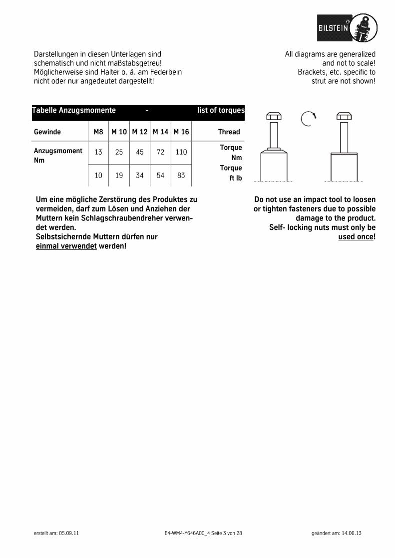
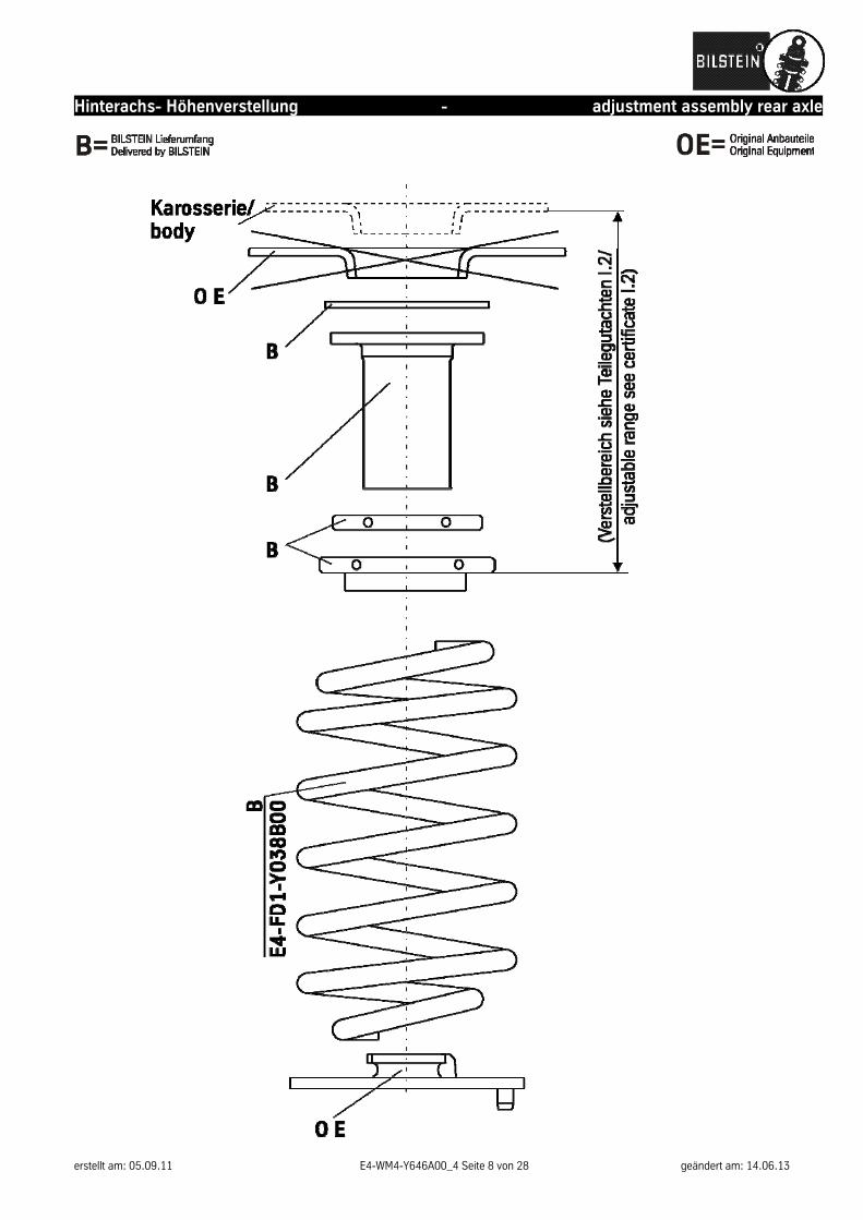
Darstellungen in diesen Unterlagen sind schematisch und nicht maßstabsgetreu! Möglicherweise sind Halter o. ä. am Federbein nicht oder nur angedeutet dargestellt!
All diagrams are generalized and not to scale!
Brackets, etc. specific to strut are not shown!
Tabelle Anzugsmomente - list of torques
Gewinde M8 M 10 M 12 M 14 M 16 Thread
Anzugsmoment Nm
13 25 45 72 110 Torque
Nm
Torque
ft lb
10 19 34 54 83
Um eine mögliche Zerstörung des Produktes zu vermeiden, darf zum Lösen und Anziehen der Muttern kein Schlagschraubendreher verwen-det werden. Selbstsichernde Muttern dürfen nur einmal verwendet werden!
Do not use an impact tool to loosen or tighten fasteners due to possible
damage to the product. Self- locking nuts must only be
used once!
erstellt am: 05.09.11 E4-WM4-Y646A00_4 Seite 4 von 28 geändert am: 14.06.13
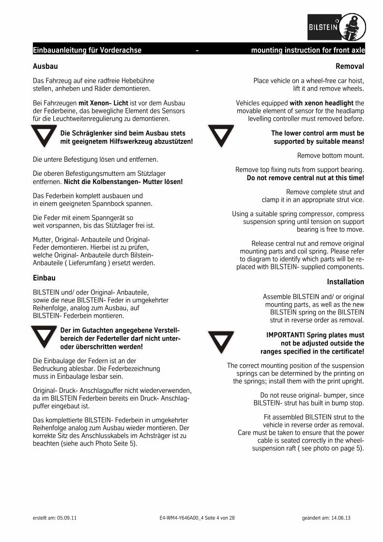
Einbauanleitung für Vorderachse - mounting instruction for front axle Ausbau Das Fahrzeug auf eine radfreie Hebebühne stellen, anheben und Räder demontieren. Bei Fahrzeugen mit Xenon- Licht ist vor dem Ausbau der Federbeine, das bewegliche Element des Sensors für die Leuchtweitenregulierung zu demontieren.
Die Schräglenker sind beim Ausbau stets mit geeignetem Hilfswerkzeug abzustützen!
Die untere Befestigung lösen und entfernen. Die oberen Befestigungsmuttern am Stützlager entfernen. Nicht die Kolbenstangen- Mutter lösen! Das Federbein komplett ausbauen und in einem geeigneten Spannbock spannen. Die Feder mit einem Spanngerät so weit vorspannen, bis das Stützlager frei ist. Mutter, Original- Anbauteile und Original- Feder demontieren. Hierbei ist zu prüfen, welche Original- Anbauteile durch Bilstein- Anbauteile ( Lieferumfang ) ersetzt werden.
Einbau BILSTEIN und/ oder Original- Anbauteile, sowie die neue BILSTEIN- Feder in umgekehrter Reihenfolge, analog zum Ausbau, auf BILSTEIN- Federbein montieren.
Der im Gutachten angegebene Verstell- bereich der Federteller darf nicht unter- oder überschritten werden!
Die Einbaulage der Federn ist an der Bedruckung ablesbar. Die Federbezeichnung muss in Einbaulage lesbar sein. Original- Druck- Anschlagpuffer nicht wiederverwenden, da im BILSTEIN Federbein bereits ein Druck- Anschlag-puffer eingebaut ist. Das komplettierte BILSTEIN- Federbein in umgekehrter Reihenfolge analog zum Ausbau wieder montieren. Der korrekte Sitz des Anschlusskabels im Achsträger ist zu beachten (siehe auch Photo Seite 5).
Removal
Place vehicle on a wheel-free car hoist, lift it and remove wheels.
Vehicles equipped with xenon headlight the movable element of sensor for the headlamp
levelling controller must removed before.
The lower control arm must be supported by suitable means!
Remove bottom mount.
Remove top fixing nuts from support bearing.
Do not remove central nut at this time!
Remove complete strut and clamp it in an appropriate strut vice.
Using a suitable spring compressor, compress
suspension spring until tension on support bearing is free to move.
Release central nut and remove original
mounting parts and coil spring. Please refer to diagram to identify which parts will be re-
placed with BILSTEIN- supplied components.
Installation
Assemble BILSTEIN and/ or original mounting parts, as well as the new
BILSTEIN spring on the BILSTEIN strut in reverse order as removal.
IMPORTANT! Spring plates must not be adjusted outside the
ranges specified in the certificate!
The correct mounting position of the suspension springs can be determined by the printing on
the springs; install them with the print upright.
Do not reuse original- bumper, since BILSTEIN- strut has built in bump stop.
Fit assembled BILSTEIN strut to the vehicle in reverse order as removal.
Care must be taken to ensure that the power cable is seated correctly in the wheel-
suspension raft ( see photo on page 5).

erstellt am: 05.09.11 E4-WM4-Y646A00_4 Seite 5 von 28 geändert am: 14.06.13
Vorderachse - front axle

erstellt am: 05.09.11 E4-WM4-Y646A00_4 Seite 6 von 28 geändert am: 14.06.13
Einbauanleitung für Hinterachse - mounting instruction for rear axle Ausbau
Das Fahrzeug auf eine radfreie Hebebühne stellen, anheben und Räder demontieren.
Die Schräglenker sind beim Ausbau stets mit geeignetem Hilfswerkzeug abzustützen!
Die obere und untere Befestigung lösen und ent-fernen. Den Stoßdämpfer komplett ausbauen und Anbauteile demontieren. Einbau
Das Original- Stützlager auf ø 12 mm aufbohren ( s. Skizze „Hinterachse“). Die Original Anbauteile entsprechend der Skizze Hinterachse entfernen, mit den BILSTEIN Anbau-teilen komplettieren und in umgekehrter Reihen-folge analog zum Ausbau auf den BILSTEIN Stoßdämpfer montieren. BILSTEIN Stoßdämpfer in umgekehrter Reihenfolge analog zum Ausbau wieder montieren.
Removal
Place vehicle on a wheel-free car hoist, lift it and remove wheel
The lower control arm must be
supported by suitable tools!
Remove top and bottom mount.
Remove complete shock absorber and original mounting parts.
Installation
Drill a hole of ø 12 mm into original support bear-ing ( see “rear axle” sketch).
Remove and modify original mounting parts
acc. to the “rear axle” sketch, complete with BILSTEIN mounting parts and fit on BILSTEIN
shock absorber in reverse order as removal.
Fit BILSTEIN shock absorber to the vehicle in reverse order as removal.

erstellt am: 05.09.11 E4-WM4-Y646A00_4 Seite 7 von 28 geändert am: 14.06.13
Hinterachse - rear axle
erstellt am: 05.09.11 E4-WM4-Y646A00_4 Seite 8 von 28 geändert am: 14.06.13
Hinterachs- Höhenverstellung - adjustment assembly rear axle

erstellt am: 05.09.11 E4-WM4-Y646A00_4 Seite 9 von 28 geändert am: 14.06.13
erstellt am: 05.09.11 E4-WM4-Y646A00_4 Seite 10 von 28 geändert am: 14.06.13

erstellt am: 05.09.11 E4-WM4-Y646A00_4 Seite 11 von 28 geändert am: 14.06.13
erstellt am: 05.09.11 E4-WM4-Y646A00_4 Seite 12 von 28 geändert am: 14.06.13
erstellt am: 05.09.11 E4-WM4-Y646A00_4 Seite 13 von 28 geändert am: 14.06.13
erstellt am: 05.09.11 E4-WM4-Y646A00_4 Seite 14 von 28 geändert am: 14.06.13
erstellt am: 05.09.11 E4-WM4-Y646A00_4 Seite 15 von 28 geändert am: 14.06.13
erstellt am: 05.09.11 E4-WM4-Y646A00_4 Seite 16 von 28 geändert am: 14.06.13

erstellt am: 05.09.11 E4-WM4-Y646A00_4 Seite 17 von 28 geändert am: 14.06.13
erstellt am: 05.09.11 E4-WM4-Y646A00_4 Seite 18 von 28 geändert am: 14.06.13

erstellt am: 05.09.11 E4-WM4-Y646A00_4 Seite 19 von 28 geändert am: 14.06.13
erstellt am: 05.09.11 E4-WM4-Y646A00_4 Seite 20 von 28 geändert am: 14.06.13

erstellt am: 05.09.11 E4-WM4-Y646A00_4 Seite 21 von 28 geändert am: 14.06.13
BILSTEIN ridecontrol
®
Lieferumfang Scope of Delivery 1 x Steuergerät ( ST)
1 x Kabelbaum ( KE) 2 m Kabel, braun, 0,75 mm² 2 m Kabel, rot, 0,75 mm² 2 m Kabel, schwarz, 0,75 mm² 3 x Stossverbinder 0,5- 1,5 mm² 3 x Kabelabzweigklemmen 0,5- 1,5 mm² 3 x Quetschverbinder ø 8,4 mm 3 x Quetschverbinder ø 6,5 mm
1 x LED- Taster ( T)
2 x Kabelverlängerung ( KV) 2,5 m
2 x Kabelverlängerung ( KV) 4,5 m 20 x Kabelbinder
1 x control unit ( ST)
1 x wiring harness ( KE): 2 m wire, brown, 0,75 mm²
2 m wire, red, 0,75 mm² 2 m wire, black, 0,75 mm²
3 x connectors 0,5- 1,5 mm² 3 x splice wire clamps 0,5- 1,5 mm²
3 x crimping connectors ø 8,4 mm 3 x crimping connectors ø 6,5 mm
1 x LED- switch ( T)
2 x extension cable ( KV) 2,5 m
2 x extension cable ( KV) 4,5 m 20 x tie straps
erstellt am: 05.09.11 E4-WM4-Y646A00_4 Seite 22 von 28 geändert am: 14.06.13
Vorbereitungen zur Montage
Entfernen Sie im Motorraum die Kunststoffabde-ckung im Bereich der Belüftung.
Legen Sie die Positionierung des BILSTEIN- Steu-ergerätes ( ST), LED- Taster ( T) für die Bedienung und Kabel ( K) fest ( Achtung! Kann je nach Fahr-zeugmodell und Ausstattungsvariante variieren).
Mögliche Positionen sind:
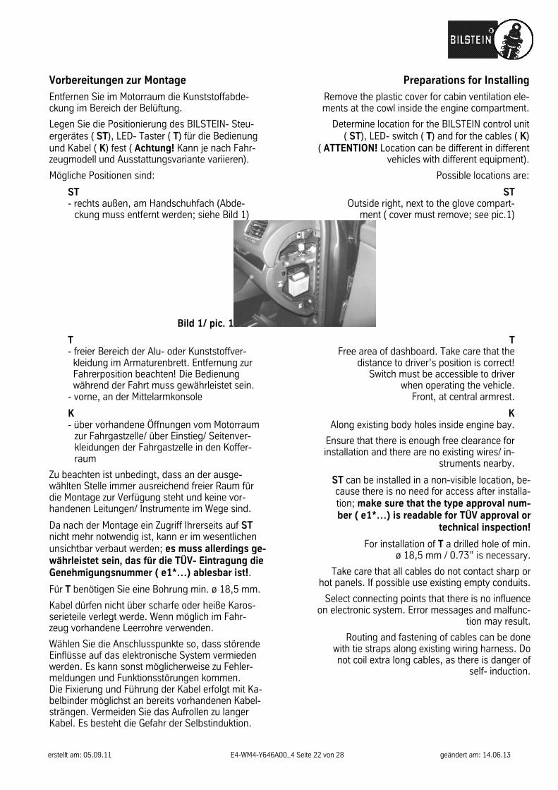
ST - rechts außen, am Handschuhfach (Abde-
ckung muss entfernt werden; siehe Bild 1)
Preparations for Installing
Remove the plastic cover for cabin ventilation ele-ments at the cowl inside the engine compartment.
Determine location for the BILSTEIN control unit ( ST), LED- switch ( T) and for the cables ( K)
( ATTENTION! Location can be different in different vehicles with different equipment).
Possible locations are:
ST Outside right, next to the glove compart-
ment ( cover must remove; see pic.1)
Bild 1/ pic. 1
T - freier Bereich der Alu- oder Kunststoffver-
kleidung im Armaturenbrett. Entfernung zur Fahrerposition beachten! Die Bedienung während der Fahrt muss gewährleistet sein.
- vorne, an der Mittelarmkonsole
K - über vorhandene Öffnungen vom Motorraum
zur Fahrgastzelle/ über Einstieg/ Seitenver-kleidungen der Fahrgastzelle in den Koffer-raum
Zu beachten ist unbedingt, dass an der ausge-wählten Stelle immer ausreichend freier Raum für die Montage zur Verfügung steht und keine vor-handenen Leitungen/ Instrumente im Wege sind.
Da nach der Montage ein Zugriff Ihrerseits auf ST nicht mehr notwendig ist, kann er im wesentlichen unsichtbar verbaut werden; es muss allerdings ge-währleistet sein, das für die TÜV- Eintragung die Genehmigungsnummer ( e1*…) ablesbar ist!.
Für T benötigen Sie eine Bohrung min. ø 18,5 mm.
Kabel dürfen nicht über scharfe oder heiße Karos-serieteile verlegt werde. Wenn möglich im Fahr-zeug vorhandene Leerrohre verwenden.
Wählen Sie die Anschlusspunkte so, dass störende Einflüsse auf das elektronische System vermieden werden. Es kann sonst möglicherweise zu Fehler-meldungen und Funktionsstörungen kommen. Die Fixierung und Führung der Kabel erfolgt mit Ka-belbinder möglichst an bereits vorhandenen Kabel-strängen. Vermeiden Sie das Aufrollen zu langer Kabel. Es besteht die Gefahr der Selbstinduktion.
T Free area of dashboard. Take care that the
distance to driver’s position is correct! Switch must be accessible to driver
when operating the vehicle. Front, at central armrest.
K Along existing body holes inside engine bay.
Ensure that there is enough free clearance for installation and there are no existing wires/ in-
struments nearby.
ST can be installed in a non-visible location, be-cause there is no need for access after installa-tion; make sure that the type approval num-ber ( e1*…) is readable for TÜV approval or
technical inspection!
For installation of T a drilled hole of min. ø 18,5 mm / 0.73” is necessary.
Take care that all cables do not contact sharp or hot panels. If possible use existing empty conduits.
Select connecting points that there is no influence on electronic system. Error messages and malfunc-
tion may result.
Routing and fastening of cables can be done with tie straps along existing wiring harness. Do not coil extra long cables, as there is danger of
self- induction.
erstellt am: 05.09.11 E4-WM4-Y646A00_4 Seite 23 von 28 geändert am: 14.06.13
Montage
( das Steuergerät wurde bei dem Prüffahrzeug im Innenraum platziert)
Verkleidung unter dem Armaturenbrett demontieren. Befestigen Sie das BILSTEIN Steuergerät mit Hilfe der beigefügten Klettklebestreifen rechts am Handschuh-fach, - Anschlüsse nach oben.
Fügen Sie die Steckerverbindung ( SV) von BIL-STEIN Steuergerät ( ST) und Kabelbaum ( KE) zu-sammen.
Der Anschluss der Klemmen KL30, KL15 und KL31 erfolgt mittels mitgelieferter Kabelschuhe am Si-cherungskasten ( SK) im Innenraum. Anschließend müssen die Kabel mit entsprechendem Kabel-schutz wieder gesichert werden.
Die einzelnen Klemmen sind zur besseren Erken-nung wie folgt beschriftet.
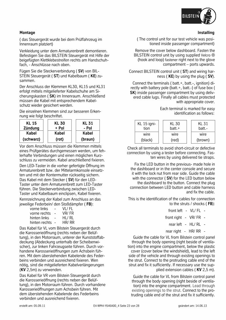
KL 15 Zündung
KL 30 + Pol
KL 31 - Pol
Kabel
(schwarz) Kabel
(rot) Kabel
(braun)
Vor dem Anschluss müssen die Klemmen mittels eines Prüfgerätes durchgemessen werden, um feh-lerhafte Verbindungen und einen möglichen Kurz-schluss zu vermeiden. Kabel anschließend fixieren. Den LED-Taster in die vorher gefertigte Öffnung im Armaturenbrett bzw. der Mittelarmkonsole einsetz-ten und mit der Kontermutter rückseitig sichern. Das Kabel mit dem Stecker ( SV) für den LED-Taster unter dem Armaturenbrett zum LED-Taster führen. Die Steckerverbindung zwischen LED-Taster und Kabelbaum einclipsen, Kabel fixieren. Kennzeichnung der Kabel zum Anschluss an das jeweilige Federbein/ den Stoßdämpfer ( FB): vorne links - VL/ FL vorne rechts - VR/ FR hinten links - HL/ RL hinten rechts - HR/ RR Das Kabel für VL vom Bilstein Steuergerät durch die Karosserieöffnung (rechts neben der Belüf-tung), in den Motorraum, unterer der Kunststoffab-deckung (Abdeckung unterhalb der Scheibenwi-scher), zur linken Fahrzeugseite führen. Durch vor-handene Karosserieöffnungen zum Achsbein füh-ren. Mit dem überstehenden Kabelende des Feder-beins verbinden und ausreichend fixieren. Wen nötig, sind die mitgelieferten Kabelverlängerungen (KV 2,5m) zu verwenden. Das Kabel für VR vom Bilstein Steuergerät durch die Karosserieöffnung (rechts neben der Belüf-tung), in den Motorraum führen. Durch vorhandene Karosserieöffnungen zum Achsbein führen. Mit dem überstehenden Kabelende des Federbeins verbinden und ausreichend fixieren.
Installing
( The control unit for our test vehicle was posi-tioned inside passenger compartment)
Remove the cover below dashboard. Fasten the BILSTEIN control unit by using supplied Velcro ®
(hook and loop) fastener right next to the glove compartment – ports upwards.
Connect BILSTEIN control unit ( ST) and wiring har-ness ( KE) by using the plug ( SV).
Connect the terminals ( batt.+, batt.-, ignition) di-rectly with battery pole (batt.+, batt.-) of fuse box ( SK) inside passenger compartment by using deliv-
ered cable lugs. Finally all cables must protected with appropriate cover.
Each terminal is marked for easy identification as follows:
KL 15 igni-tion
KL 30 batt.+
KL 31 batt.-
wire (black)
wire (red)
wire (brown)
Check all terminals to avoid short-circuit or defective connection by using a tester before connecting. Fas-
ten wires by using delivered tie straps.
Fix the LED button in the previous- made hole in the dashboard or in the center console and secure it with the lock nut from rear side. Guide the cable with the connector ( SV) for the LED button below
the dashboard to the button. Connect the plug connection between LED button and cable harness
and fix the cable.
This is the identification of the cables for connection to the struts / shocks ( FB):
front left - VL/ FL -
front right - VR/ FR -
rear left - HL/ RL -
rear right - HR/ RR -
Guide the cable for VL from Bilstein control panel through the body opening (right beside of ventila-
tion) into the engine compartment, below the plastic cover (cover below the windshield), lead to the left
side of the vehicle and through existing openings to the strut. Connect to the protruding cable end of the strut and fix it sufficiently. If necessary use the sup-
plied extension cables ( KV 2,5 m).
Guide the cable for VL from Bilstein control panel through the body opening (right beside of ventila-tion) into the engine compartment. Lead through
existing openings to the strut. Connect to the pro-truding cable end of the strut and fix it sufficiently.
erstellt am: 05.09.11 E4-WM4-Y646A00_4 Seite 24 von 28 geändert am: 14.06.13
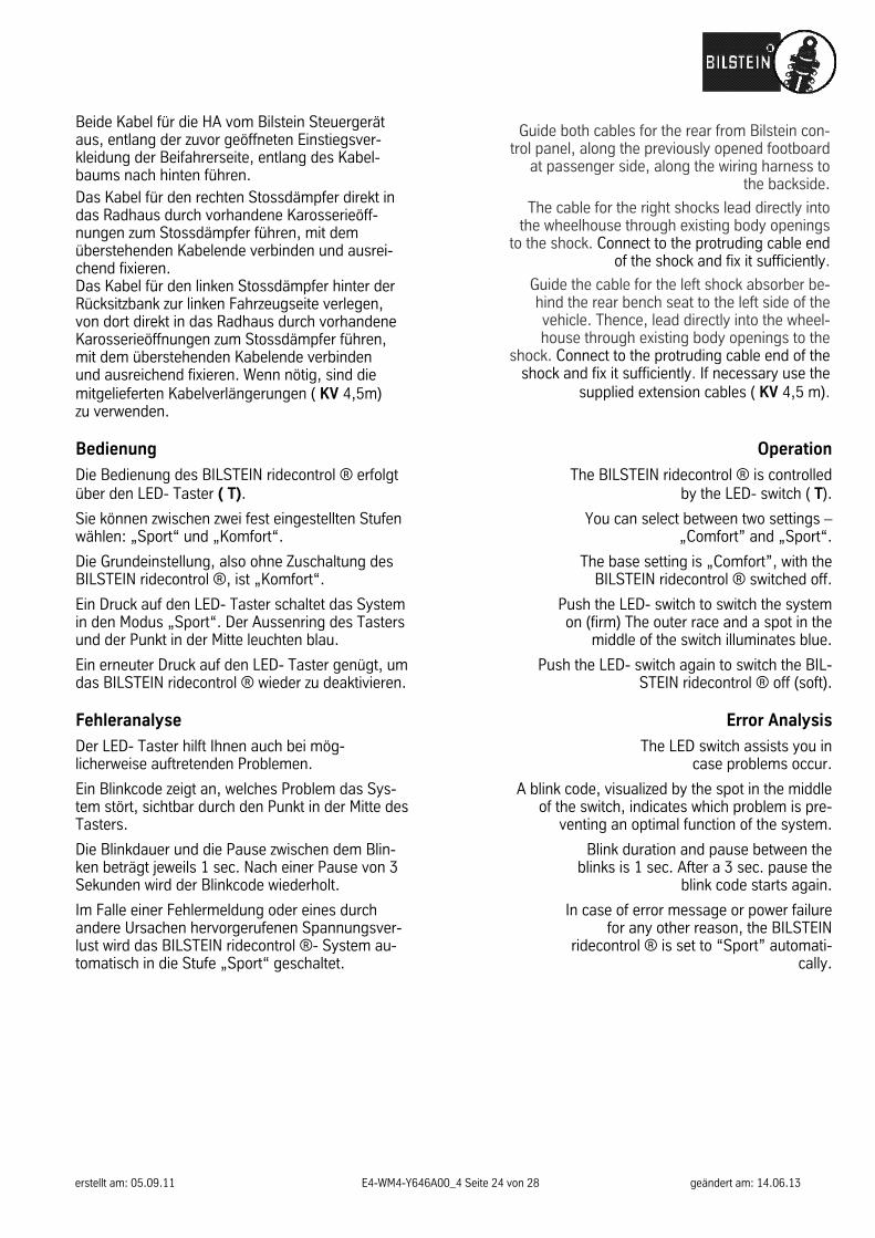
Beide Kabel für die HA vom Bilstein Steuergerät aus, entlang der zuvor geöffneten Einstiegsver-kleidung der Beifahrerseite, entlang des Kabel-baums nach hinten führen. Das Kabel für den rechten Stossdämpfer direkt in das Radhaus durch vorhandene Karosserieöff-nungen zum Stossdämpfer führen, mit dem überstehenden Kabelende verbinden und ausrei-chend fixieren. Das Kabel für den linken Stossdämpfer hinter der Rücksitzbank zur linken Fahrzeugseite verlegen, von dort direkt in das Radhaus durch vorhandene Karosserieöffnungen zum Stossdämpfer führen, mit dem überstehenden Kabelende verbinden und ausreichend fixieren. Wenn nötig, sind die mitgelieferten Kabelverlängerungen ( KV 4,5m) zu verwenden.
Guide both cables for the rear from Bilstein con-trol panel, along the previously opened footboard
at passenger side, along the wiring harness to the backside.
The cable for the right shocks lead directly into the wheelhouse through existing body openings
to the shock. Connect to the protruding cable end of the shock and fix it sufficiently.
Guide the cable for the left shock absorber be-hind the rear bench seat to the left side of the vehicle. Thence, lead directly into the wheel-house through existing body openings to the
shock. Connect to the protruding cable end of the shock and fix it sufficiently. If necessary use the
supplied extension cables ( KV 4,5 m).
Bedienung
Die Bedienung des BILSTEIN ridecontrol ® erfolgt über den LED- Taster ( T).
Sie können zwischen zwei fest eingestellten Stufen wählen: „Sport“ und „Komfort“.
Die Grundeinstellung, also ohne Zuschaltung des BILSTEIN ridecontrol ®, ist „Komfort“.
Ein Druck auf den LED- Taster schaltet das System in den Modus „Sport“. Der Aussenring des Tasters und der Punkt in der Mitte leuchten blau.
Ein erneuter Druck auf den LED- Taster genügt, um das BILSTEIN ridecontrol ® wieder zu deaktivieren.
Operation
The BILSTEIN ridecontrol ® is controlled by the LED- switch ( T).
You can select between two settings – „Comfort” and „Sport“.
The base setting is „Comfort”, with the BILSTEIN ridecontrol ® switched off.
Push the LED- switch to switch the system on (firm) The outer race and a spot in the
middle of the switch illuminates blue.
Push the LED- switch again to switch the BIL-STEIN ridecontrol ® off (soft).
Fehleranalyse
Der LED- Taster hilft Ihnen auch bei mög-licherweise auftretenden Problemen.
Ein Blinkcode zeigt an, welches Problem das Sys-tem stört, sichtbar durch den Punkt in der Mitte des Tasters.
Die Blinkdauer und die Pause zwischen dem Blin-ken beträgt jeweils 1 sec. Nach einer Pause von 3 Sekunden wird der Blinkcode wiederholt.
Im Falle einer Fehlermeldung oder eines durch andere Ursachen hervorgerufenen Spannungsver-lust wird das BILSTEIN ridecontrol ®- System au-tomatisch in die Stufe „Sport“ geschaltet.
Error Analysis
The LED switch assists you in case problems occur.
A blink code, visualized by the spot in the middle of the switch, indicates which problem is pre-
venting an optimal function of the system.
Blink duration and pause between the blinks is 1 sec. After a 3 sec. pause the
blink code starts again.
In case of error message or power failure for any other reason, the BILSTEIN
ridecontrol ® is set to “Sport” automati-cally.
erstellt am: 05.09.11 E4-WM4-Y646A00_4 Seite 25 von 28 geändert am: 14.06.13
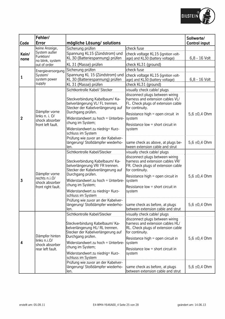
Code Fehler/ Error mögliche Lösung/ solutions
Sollwerte/ Control input
Kein/ none
keine Anzeige, System außer Funktion/ no blink, system out of order
Sicherung prüfen check fuse Spannung KL15 (Zündstrom) und KL 30 (Batteriespannung) prüfen
check voltage KL15 (ignition volt-age) and KL30 (battery voltage) 6,8 - 16 Volt
KL 31 (Masse) prüfen check KL31 (ground)
1
Energieversorgung System/ system power supply
Sicherung prüfen check fuse Spannung KL 15 (Zündstrom) und KL 30 (Batteriespannung) prüfen
check voltage KL15 (ignition volt-age) and KL30 (battery voltage) 6,8 - 16 Volt
KL 31 (Masse) prüfen check KL31 (ground)
2
Dämpfer vorne links n. i. O/ shock absorber front left fault.
Sichtkontrolle Kabel/ Stecker visually check cable/ plugs
Steckverbindung Kabelbaum/ Ka-belverlängerung VL/ FL trennen. Stecker der Kabelverlängerung auf Durchgang prüfen.
Widerstandwert zu hoch = Unterbre-chung im System;
Widerstandwert zu niedrig= Kurz-schluss im System
disconnect plugs between wiring harness and extension cables VL/ FL. Check plugs of extension cable for continuity.
Resistance high = open circuit in system
Resistance low = short circuit in system
5,6 ±0,4 Ohm
Prüfung wie zuvor an der Kabelver-längerung/ Stoßdämpfer wiederho-len.
same check as above, at plugs be-tween extension cable and strut
5,6 ±0,4 Ohm
3
Dämpfer vorne rechts n.i.O/ shock absorber front right fault.
Sichtkontrolle Kabel/Stecker visually check cable/ plugs
Steckverbindung Kabelbaum/ Ka-belverlängerung VR/ FR trennen. Stecker der Kabelverlängerung auf Durchgang prüfen.
Widerstandwert zu hoch = Unterbre-chung im System;
Widerstandwert zu niedrig= Kurz-schluss im System
disconnect plugs between wiring harness and extension cables VR/ FR. Check plugs of extension cable for continuity.
Resistance high = open circuit in system
Resistance low = short circuit in system
5,6 ±0,4 Ohm
Prüfung wie zuvor an der Kabelver-längerung/ Stoßdämpfer wiederho-len.
same check as before, at plugs between extension cable and strut
5,6 ±0,4 Ohm
4
Dämpfer hinten links n.i.O/ shock absorber rear left fault.
Sichtkontrolle Kabel/Stecker visually check cable/ plugs
Steckverbindung Kabelbaum/ Ka-belverlängerung HL/ RL trennen. Stecker der Kabelverlängerung auf Durchgang prüfen.
Widerstandwert zu hoch = Unterbre-chung im System;
Widerstandwert zu niedrig= Kurz-schluss im System
disconnect plugs between wiring harness and extension cables HL/ RL. Check plugs of extension cable for continuity.
Resistance high = open circuit in system
Resistance low = short circuit in system
5,6 ±0,4 Ohm
Prüfung wie zuvor an der Kabelver-längerung/ Stoßdämpfer wiederho-len.
same check as before, at plugs between extension cable and strut
5,6 ±0,4 Ohm
erstellt am: 05.09.11 E4-WM4-Y646A00_4 Seite 26 von 28 geändert am: 14.06.13
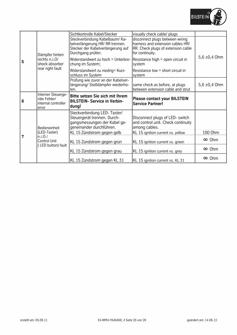
5
Dämpfer hinten rechts n.i.O/ shock absorber rear right fault
Sichtkontrolle Kabel/Stecker visually check cable/ plugs Steckverbindung Kabelbaum/ Ka-belverlängerung HR/ RR trennen. Stecker der Kabelverlängerung auf Durchgang prüfen.
Widerstandwert zu hoch = Unterbre-chung im System;
Widerstandwert zu niedrig= Kurz-schluss im System
disconnect plugs between wiring harness and extension cables HR/ RR. Check plugs of extension cable for continuity.
Resistance high = open circuit in system
Resistance low = short circuit in system
5,6 ±0,4 Ohm
Prüfung wie zuvor an der Kabelver-längerung/ Stoßdämpfer wiederho-len.
same check as before, at plugs between extension cable and strut
5,6 ±0,4 Ohm
6
Interner Steuerge-räte Fehler/ internal controller error
Bitte setzen Sie sich mit Ihrem BILSTEIN- Service in Verbin-dung!
Please contact your BILSTEIN Service Partner!
7
Bedieneinheit (LED-Taster) n.i.O./ Control Unit ( LED button) fault
Steckverbindung LED- Taster/ Steuergerät trennen. Durch-gangsmessungen der Kabel ge-geneinander durchführen.
Disconnect plugs of LED- switch and control unit. Check continuity among cables.
KL 15 Zündstrom gegen gelb KL 15 ignition current vs. yellow 100 Ohm
KL 15 Zündstrom gegen grün KL 15 ignition current vs. green ∞ Ohm
KL 15 Zündstrom gegen grau KL 15 ignition current vs. grey ∞ Ohm
KL 15 Zündstrom gegen KL 31 KL 15 ignition current vs. KL 31 ∞ Ohm
erstellt am: 05.09.11 E4-WM4-Y646A00_4 Seite 27 von 28 geändert am: 14.06.13
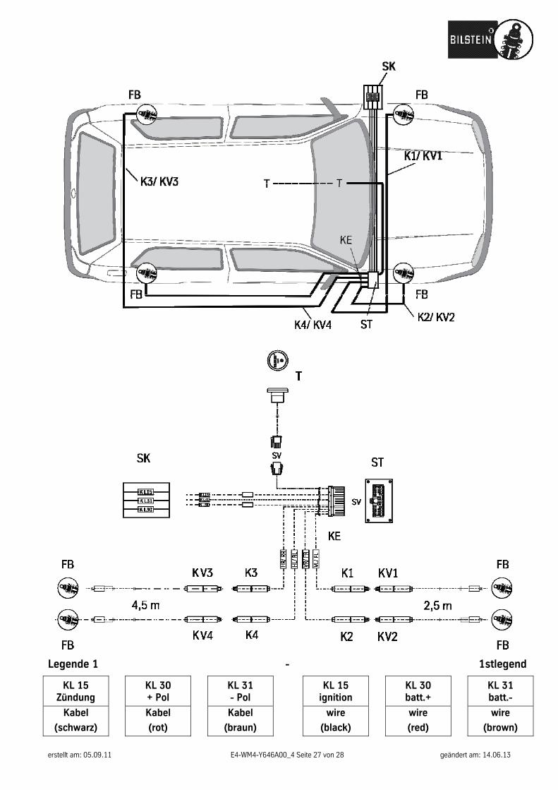
Legende 1 - 1stlegend
KL 15 Zündung
KL 30 + Pol
KL 31 - Pol
KL 15 ignition
KL 30 batt.+
KL 31 batt.-
Kabel
(schwarz) Kabel
(rot) Kabel
(braun)
wire
(black)
wire
(red)
wire
(brown)

erstellt am: 05.09.11 E4-WM4-Y646A00_4 Seite 28 von 28 geändert am: 14.06.13
ThyssenKrupp Bilstein GmbHMilsper Straße 214; D-58256 Ennepetal
Postfach 1151, D-58240 EnnepetalPhone: +49 2333 791-4444
Fax: +49 2333 [email protected], www.bilstein.de