Operating Instructions - Pfeuffer
34
Artikelnummer Betriebsanleitung: 1745 9001 Item no. operating instructions: Pfeuffer GmbH Flugplatzstraße 70 97318 Kitzingen GERMANY Phone: +49 9321 9369–0 [email protected] Revision 5/30.09.2021 www.pfeuffer.com Translation of the original operating instructions Operating Instructions Sample Divider Vario 1G / 2H / 4-8
Transcript of Operating Instructions - Pfeuffer

Artikelnummer Betriebsanleitung: 1745 9001 Item no. operating instructions:
Pfeuffer GmbH Flugplatzstraße 70 97318 Kitzingen GERMANY Phone: +49 9321 9369–0 [email protected] Revision 5/30.09.2021 www.pfeuffer.com Translation of the original operating instructions
Operating Instructions Sample Divider Vario 1G / 2H / 4-8

Translation If the system is being supplied or subsequently sold to countries of the EEA, the Operating Instructions must be translated into the language of the country of use accordingly. If there are any discrepancies with the translated text, then use the original Operating Instructions (German version) or contact the manufacturer.
Operating Instructions in electronic format PDFs of the original Operating Instructions (German version) and translations of the original Operating Instructions can be requested by e-mail: [email protected]. Ensure the correct type designation and serial number is stated!
© Copyright The passing on or reproduction of this document, and use and disclosure of its contents are prohibited unless expressly permitted. We will claim compensation for damages. All rights reserved with regard to the granting of patents, utility models or designs. (DIN ISO 16016)
2 | 34 Operating Instructions Sample Divider Vario | Revision 5
These Operating Instructions are a constituent part of the Vario sample divider and must be available to all operating personnel at all times. They are intended for the operating company of the system, the operating personnel and the specialists who are responsible for the transport, assembly, installation, operation, maintenance, cleaning, disassembly and disposal. The Pfeuffer GmbH has prepared and reviewed these Operating Instructions with the greatest care. However, no guarantee is made for its completeness or accuracy. Subject to technical modifications.
Table of contents
Revision 5 | Operating Instructions Sample Divider Vario 3 | 34
1 Introduction ............................................................................................................................... 5
1.1 Intended use ............................................................................................................................... 5
1.2 Declaration of Conformity .......................................................................................................... 6
1.3 Design characteristics of hazard warnings ................................................................................. 7
1.4 Pictograms in the Operating Instructions .................................................................................. 8
1.5 Designation ................................................................................................................................. 8
2 Safety ........................................................................................................................................ 9
2.1 Installed safety systems ............................................................................................................. 9
2.1.1 Supply isolating device (plug/socket combination) ....................................................... 9
2.1.2 System control ............................................................................................................... 9
2.1.3 Protective caps ............................................................................................................ 10
2.2 Interfaces at sample divider ..................................................................................................... 10
2.3 Operating and hazard areas associated with the machine ...................................................... 10
2.4 Operating and maintenance personnel ................................................................................... 11
2.5 Safety measures (to be implemented by the operating company) ......................................... 11
2.6 General safety instructions ....................................................................................................... 12
2.7 Safety tests ............................................................................................................................... 13
2.8 Residual hazards associated with the Vario sample divider .................................................... 13
2.9 Switch-off procedure ................................................................................................................ 13
3 Technical data .......................................................................................................................... 14
3.1 Dimensions and weight ............................................................................................................ 14
3.2 Power supply ............................................................................................................................ 14
3.3 General information ................................................................................................................. 14
3.4 Agitator (option) ....................................................................................................................... 14
4 Delivery, transport and storage ................................................................................................ 15
4.1 Scope of delivery ...................................................................................................................... 15
4.2 Transport and packaging .......................................................................................................... 15
4.3 Temporary storage ................................................................................................................... 15
4.4 Transport to installation location (of customer) ...................................................................... 16
5 Function .................................................................................................................................. 17
5.1 Components of Vario sample divider ....................................................................................... 17
5.2 Functional sequence ................................................................................................................ 18
6 Installation and commissioning ................................................................................................ 19

Table of contents
4 | 34 Operating Instructions Sample Divider Vario | Revision 5
7 Operation ................................................................................................................................ 20
7.1 Control elements ...................................................................................................................... 20
7.1.1 ON/OFF operating switch ............................................................................................ 20
7.1.2 Adjustment lever division ratio ................................................................................... 20
7.2 Settings ..................................................................................................................................... 20
7.2.1 Dividing time ................................................................................................................ 20
7.2.2 Circumferential velocity ............................................................................................... 21
7.2.3 Scale ............................................................................................................................. 21
7.3 Division ratio Vario sample divider 1G ..................................................................................... 22
7.4 Division ratio Vario sample divider 2H ..................................................................................... 22
7.5 Division ratio Vario sample divider 4-8 .................................................................................... 23
7.6 Division of samples ................................................................................................................... 23
7.6.1 Scheme Vario sample divider 1G/8 (minimal) – scale 4 .............................................. 24
7.6.2 Scheme Vario sample divider 1G/8 – scale 22............................................................. 25
7.6.3 Scheme Vario sample divider 2H (minimal) – scale 4 .................................................. 26
7.6.4 Scheme Vario sample divider 2H – scale 22 ................................................................ 27
7.6.5 Scheme Vario sample divider 4-8 (4 collecting pans) – scale 4 ................................... 28
7.6.6 Scheme Vario sample divider 4-8 (4 collecting pans) – scale 11 ................................. 29
8 Maintenance and cleaning ....................................................................................................... 30
8.1 Cleaning .................................................................................................................................... 30
8.2 Inspection interval and function test ....................................................................................... 30
8.3 Maintenance ............................................................................................................................. 31
8.4 General maintenance instructions ........................................................................................... 31
8.5 Check ........................................................................................................................................ 31
9 Malfunctions – causes and rectification .................................................................................... 32
10 Spare and wearing parts........................................................................................................... 32
11 Supplements and accessories ................................................................................................... 33
12 Emergency ............................................................................................................................... 34
13 Dismantling and disposal ......................................................................................................... 34

Introduction
Revision 5 | Operating Instructions Sample Divider Vario 5 | 34
1 Introduction
1.1 Intended use
The Vario sample divider is used for dividing up samples of grain-like crops (agricultural seed) into sub-samples. The division procedure is used for achieving representative sub-samples.
The Vario sample divider is designed as a portable machine with a power plug.
Private use of the machine is prohibited.
NOTICE The Vario sample divider was designed solely for the aforementioned purpose.
Using it for any other purpose or modifying it without the written consent of the Pfeuffer GmbH is not considered to be in compliance with the intended use.
The Pfeuffer GmbH shall not be liable for the resulting damage. Damage caused by such an unintended use is at the sole risk of the operator.
The sample divider is not suitable for the division of • flour, dust and grit • liquid, sticky and oily products • objects made of metal, stone, concrete, plastic or other foreign components.
The Vario sample divider is allowed to be operated only if it is ensured that all the safety devices are functional and the system in which this machine is installed complies with the EU directives.
The samples to be used for the correct operation of the Vario sample divider are provided by the operator.
The operator bears sole responsibility for the proper handling of these materials and the associated dangers.
Hazard notes and instructions for disposal must be provided by the operator.
Intended use includes also the compliance with the Instruction Manual and User´s Guide as well as the maintenance and servicing conditions, as specified in these Operating Instructions.
These Operating Instructions do not relieve the operating company of the obligation to develop and to apply independent health and/or safety regulations or safe working processes which are aimed at the requirements of the overall machine, as well as the obligation to monitor their compliance.

Introduction
6 | 34 Operating Instructions Sample Divider Vario | Revision 5
1.2 Declaration of Conformity
EC/EU Declaration of Conformity
In terms oft he directives: - Machinery 2006/42/EC - Electromagnetic compatibility 2014/30/EU
Manufacturer: Pfeuffer GmbH Phone: 09321 9369-0 Flugplatzstraße 70 [email protected] 97318 Kitzingen www.pfeuffer.com GERMANY
This Declaration of Conformity is issued under the sole responsibility of the manufacturer.
Person authorized to compile technical documents: Lothar Pfeuffer, General Manager
Product: Vario sample divider
Type: 1G 2H 4-8
Serial number: ___________________________
The product mentioned above fulfils the requirements of the following applicable directives and standards:
DIN EN ISO 12100: 2010
DIN EN 60204-1: 2006
DIN EN 61000-6-2:2006
DIN EN 61000-6-3:2007
This declaration shall become null and void should any alterations be made to the machine without our approval.
Kitzingen, _______________________ ________________________________________ Lothar Pfeuffer, General Manager

Introduction
Revision 5 | Operating Instructions Sample Divider Vario 7 | 34
1.3 Design characteristics of hazard warnings
The Pfeuffer GmbH Operating Instructions contain information which must be observed for the sake of your personal safety and to avoid damage to property. Information concerning your personal safety is shown by means of a triangle.
Note the following categories of hazard warnings and explanation of symbols:
Pictogram
SIGNAL WORD
Type of hazard and its source.
Possible result of its disregard.
Measure to ward off the hazard.
DANGER
warns against a very dangerous situation that results in death or serious injuries.
WARNING
warns against a dangerous situation that can potentially result in death or serious injuries.
CAUTION
warns against a potentially dangerous situation that results in minor or moderate injuries.
NOTICE warns against situations that are dangerous for the product and/or the environment.
Introduction
8 | 34 Operating Instructions Sample Divider Vario | Revision 5
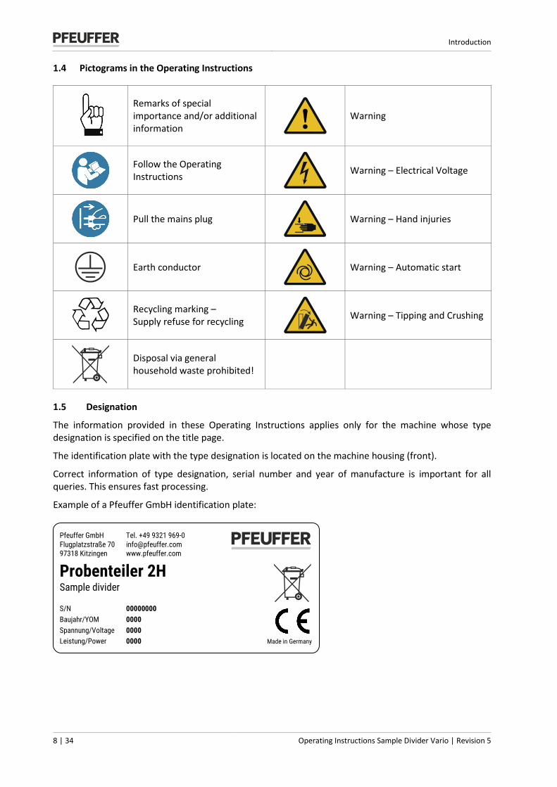
1.4 Pictograms in the Operating Instructions
Remarks of special importance and/or additional information
Warning
Follow the Operating Instructions
Warning – Electrical Voltage
Pull the mains plug
Warning – Hand injuries
Earth conductor
Warning – Automatic start
Recycling marking – Supply refuse for recycling
Warning – Tipping and Crushing
Disposal via general household waste prohibited!
1.5 Designation
The information provided in these Operating Instructions applies only for the machine whose type designation is specified on the title page.
The identification plate with the type designation is located on the machine housing (front).
Correct information of type designation, serial number and year of manufacture is important for all queries. This ensures fast processing.
Example of a Pfeuffer GmbH identification plate:
Pfeuffer GmbH Tel. +49 9321 969-0 Flugplatzstraße 70 [email protected] 97318 Kitzingen www.pfeuffer.com
Probenteiler 2H Sample divider S/N 00000000 Baujahr/YOM 0000 Spannung/Voltage 0000 Leistung/Power 0000 Made in Germany

Safety
Revision 5 | Operating Instructions Sample Divider Vario 9 | 34
2 Safety
NOTICE It is strictly forbidden to disable the safety devices or to change their mode of operation.
2.1 Installed safety systems
The installed safety systems must be checked with corresponding test methods at regular testing intervals; refer to the following table:
Test intervals Test methods
d = daily w = weekly m = monthly ¼ y = quarterly ½ y = half-yearly y = yearly
VI = visual inspection FT = functional test M = measurement
2.1.1 Supply isolating device (plug/socket combination)
The plug/socket combination simultaneously functions as an EMERGENCY STOP device.
In case of an emergency, disconnect the sample divider from the electrical power supply.
Secure the plug suitably against unauthorized re-plugging by placing it where it can remain under constant supervision.
Set the plug/socket combination in such a way that it can be easily seen and is quickly accessible in case of an emergency.
Test
Interval Method y FT
2.1.2 System control
The system is controlled internally with a supply system, a phase and an earth connection (with green/yellow covering for the wires).
Test Interval Method
y VI, FT, M

Safety
10 | 34 Operating Instructions Sample Divider Vario | Revision 5
2.1.3 Protective caps
Test During the operation, sample divider is protected against interference affecting the machine using protective caps. Interval Method
m VI
Figure 1: Overview - Protective caps model 2H
Pos. Name 1 Removable lid 2 Solid screwed case
2.2 Interfaces at sample divider
Figure 2: Interfaces model 2H
Pos. Name 1 Sample fill in 2 Sample outlet
2.3 Operating and hazard areas associated with the machine
Operating area Ensure a sufficient working height (depending on the body size of the operating personnel) of approximately 60-65 cm. For this, a suitable base frame is necessary so that the operating personnel can access the collecting pans ergonomically.
Hazard area The entire area of one meter around the machine is dangerous during adjustment, maintenance and repair work.
Do not keep any objects around the machine.
1
2
ON
OFF
1
2
ON
OFF
Safety
Revision 5 | Operating Instructions Sample Divider Vario 11 | 34
2.4 Operating and maintenance personnel Operating and maintenance personnel are responsible for transport, assembly, installation, operation and cleaning of the Vario sample divider as well as for fault rectification.
1. The sample divider is allowed to be operated by authorized personnel and instructed persons only.
2. The responsibilities associated with operating the machine must be clearly defined and adhered to so that there are no unclear competencies concerning safety.
3. The deactivation procedures specified in these Operating Instructions must be adhered to for all tasks (operation, maintenance, repairs etc.) refer to chapter 2.9.
4. The operator must forbid all the methods of operation that compromise the safety levels associated with the sample divider.
5. The operator must also ensure that only authorized persons work on the sample divider.
6. The operator is obliged to immediately inform the operating company about changes in the sample divider that compromise safety.
7. The operator must provide the operating personnel with the appropriate protective equipment in accordance with the legal obligations and the material to be processed.
8. The operator must regularly demand that the personal safety equipment is used. The operator must also monitor the usage of this equipment.
2.5 Safety measures (to be implemented by the operating company)
It is noted that the operating company
trains the operating and maintenance personnel with regard to the safety devices of the sample divider.
and monitors their compliance with the safety measures.
The frequency of functional tests described in chapter 8.3 must be adhered to.
The tasks described in these Operating Instructions are listed in such a way that they are
understood by the operating personnel (with regard to the Function and Operation chapters).
understood by skilled personnel (with regard to the chapters Delivery, transport and storage, installation and commissioning, maintenance and cleaning, disruptions – causes and their rectification and Dismantling and disposal).
The chapters Delivery, transport and storage, installation and commissioning, maintenance and cleaning, disruptions – causes and their rectification and Dismantling and disposal are only intended for skilled personnel. Tasks that are described in these chapters must be carried out by skilled personnel only.
Instructed person A person who has been instructed and, if necessary, trained by a skilled worker about the assigned tasks and possible dangers in case of improper behavior, and how has been instructed about the necessary safety devices and safety measures.
Skilled worker An individual who is proficient in identifying risks and avoiding hazards that can occur when using the product, on account of their relevant professional training, education and/or experience. (Definition as per DIN EN 82079-1:2013-06)

Safety
12 | 34 Operating Instructions Sample Divider Vario | Revision 5
Obligations of the operator
In the European Economic Area (EEA), the national implementation of framework directive 89/391/EEC and the relevant specific directives (especially directive 2009/104/EC "about the minimum requirements for safety and health protection in case of the use of equipment by workers") must be considered and adhered to, with regard to the version that is currently valid.
In addition, the local legal provisions for the following must be adhered to:
the safety of the personnel (accident prevention regulations)
the accident prevention regulation DGUV Directive 3 (formerly BGV A 3) "electrical systems and means of production" (DGUV = German Statutory Accident Insurance Association)
the safety of work equipment (protective equipment and maintenance)
the permitted noise load (depending on the site and time of day)
the disposal of the product (waste disposal act)
the disposal of the material (waste disposal act)
cleaning (cleaning agent and disposal)
the hazardous materials (in Germany, the Technical Rule for Hazardous Materials – TRGS 555 applies)
the environmental protection requirements
Electrical connections
The sample divider may only be connected to a correctly-earthed socket with an earth conductor.
Illumination intensity
The operator must ensure sufficient and proper intensity of illumination in all the areas of the machine.
At least 300 lux is expected (maintenance value).
ASR A3.4 is applicable in Germany (Technical rules for workplaces – Lighting).
2.6 General safety instructions
The safety equipment and safety instructions described in these Operating Instructions must be borne in mind.
1. Disconnect the sample divider from the mains in case of malfunctioning.
2. Disconnect the sample divider from mains before starting with the cleaning operation.
3. Do not let the sample divider get wet during transport, storage, cleaning and operation.
4. Make sure that you only use the sample divider when it is in a defect-free condition.
5. Never touch the mains cable with wet hands.
6. Always use original spare parts and accessories (refer to chapter 10 and 11).
Safety
Revision 5 | Operating Instructions Sample Divider Vario 13 | 34
2.7 Safety tests
The following safety tests have been conducted by Pfeuffer GmbH at the plant: Test and inspection as per standard DIN EN 60204-1:
Inspection to verify that the electrical equipment complies with the technical documentation.
Continous connection of protective conductor system
Insulation resistance tests
Voltage tests
Functional tests The functions of the electric equipment, especially those that relate to safety and safety measures, have been tested.
2.8 Residual hazards associated with the Vario sample divider
Pay attention to electrical hazards in case of all tasks that are to be carried out vis-a-vis electrically-operated components.
Be mindful of crushing hazards when setting up, servicing, repairing and operating the machine.
Make sure that the sample divider starts automatically when the mains plug is plugged in and the power supply is periodic.
2.9 Switch-off procedure
DANGER
Touching live parts can be fatal! The following deactivation procedure must be carried out before cleaning, maintaining or repairing the machine (only by skilled personnel):
Deplete the sample divider.
Disconnect the plug/socket combination from the power supply.
It must be possible to ensure that the plug remains under the direct supervision of the person in the hazardous area.
Make sure that water, vapor or dust cannot enter the electronic area when cleaning.

Technical data
14 | 34 Operating Instructions Sample Divider Vario | Revision 5
3 Technical data
Sample divider Vario Division of all grain crops Sample quantity ca. 1-8 kg Material/transported material Grains, peas, rape seed, maize and similar granular bulk goods
3.1 Dimensions and weight
Model 1G Model 2H Model 4-8 Height 800 mm 840 mm 840 mm Width 465 mm 485 mm 550 mm Length 492 mm 492 mm 492 mm Weight 65 kg 60 kg 72 kg
3.2 Power supply
Supply voltage/Frequency 230 V ~ 50/60 Hz (115 V ~ 60 Hz on request) Power 100 VA Power consumption 60 W Number of phases 1 Ph / PE Earth conductor PE (yellow/green) in mains cable Frequency ±1 % Installation instructions Executed as per VDE
3.3 General information
Ambient temperature Storage and transport -10 °C to +60 °C
Ambient temperature during operation +5 °C to +40 °C
Humidity 20 % to 80 % non-condensing Acoustic level LPA = 60 dB(A) as per measurement report Protection level according to DIN EN 60529 IP 10 (Housing), IP 54 (Motor)
3.4 Agitator (option)
Supply voltage/Frequency 230 V ~ 50 Hz Power 6 VA Protection level according to DIN EN 60529 IP10
Installation instructions Executed as per VDE
Delivery, transport and storage
Revision 5 | Operating Instructions Sample Divider Vario 15 | 34
4 Delivery, transport and storage
The chapter Delivery, transport and storage is intended for skilled personnel only.
4.1 Scope of delivery
The scope of delivery to the operator includes:
Vario sample divider 1G with standard funnel Item no. 1745 0057
(Capacity ca. 3 kg) Ø 48 mm / 12 kg/min • 1 PVC collecting pan • 1 Sample pan for flow • Operating Instructions
Vario sample divider 2H with standard funnel Item no. 1745 0050
(Capacity ca. 3 kg) Ø 48 mm / 12 kg/min • Extension funnel capacity up to 8 kg • 2 PVC collecting pans • 1 Sample pan for flow • Operating Instructions
Vario sample divider 4-8 with standard funnel Item no. 1745 0053
(Capacity ca. 3 kg) Ø 48 mm / 12 kg/min • Accessories according to delivery order • Operating Instructions
4.2 Transport and packaging
Systems and machines of Pfeuffer GmbH are carefully checked and packaged before dispatching. However, damages during the transport cannot be excluded.
Intake control
Run a completeness check using the delivery note.
In case of damages
Check the delivery for damages (visual inspection).
In case of complaints
If the delivery has been damaged during transport:
Retain the packaging (for the dispatcher to inspect or for return delivery).
Immediately inform the suppliers or Pfeuffer GmbH.
4.3 Temporary storage
Freight packaging of the Vario sample divider and exchange parts and accessories is intended for a storage duration of six months upon delivery.
Storage conditions
Closed and dry room with a room temperature from minimum -10 °C to maximum +60 °C.
Delivery, transport and storage
16 | 34 Operating Instructions Sample Divider Vario | Revision 5
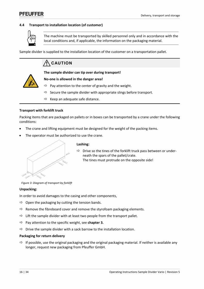
4.4 Transport to installation location (of customer)
The machine must be transported by skilled personnel only and in accordance with the local conditions and, if applicable, the information on the packaging material.
Sample divider is supplied to the installation location of the customer on a transportation pallet.
CAUTION
The sample divider can tip over during transport!
No-one is allowed in the danger area!
Pay attention to the center of gravity and the weight.
Secure the sample divider with appropriate slings before transport.
Keep an adequate safe distance.
Transport with forklift truck
Packing items that are packaged on pallets or in boxes can be transported by a crane under the following conditions:
• The crane and lifting equipment must be designed for the weight of the packing items.
• The operator must be authorized to use the crane.
Figure 3: Diagram of transport by forklift
Lashing:
Drive so the tines of the forklift truck pass between or under-neath the spars of the pallet/crate. The tines must protrude on the opposite side!
Unpacking:
In order to avoid damages to the casing and other components,
Open the packaging by cutting the tension bands.
Remove the fibreboard cover and remove the styrofoam packaging elements.
Lift the sample divider with at least two people from the transport pallet.
Pay attention to the specific weight, see chapter 3.
Drive the sample divider with a sack barrow to the installation location.
Packaging for return delivery
If possible, use the original packaging and the original packaging material. If neither is available any longer, request new packaging from Pfeuffer GmbH.
Function
Revision 5 | Operating Instructions Sample Divider Vario 17 | 34
5 Function
5.1 Components of Vario sample divider
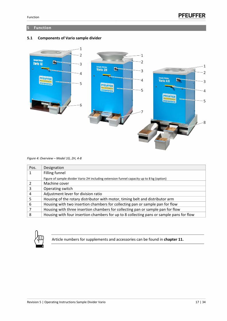
Figure 4: Overview – Model 1G, 2H, 4-8
Pos. Designation 1 Filling funnel
Figure of sample divider Vario 2H including extension funnel capacity up to 8 kg (option) 2 Machine cover 3 Operating switch 4 Adjustment lever for division ratio 5 Housing of the rotary distributor with motor, timing belt and distributor arm 6 Housing with two insertion chambers for collecting pan or sample pan for flow 7 Housing with three insertion chambers for collecting pan or sample pan for flow 8 Housing with four insertion chambers for up to 8 collecting pans or sample pans for flow
Article numbers for supplements and accessories can be found in chapter 11.

Function
18 | 34 Operating Instructions Sample Divider Vario | Revision 5
5.2 Functional sequence
Figure 5: Functional sequence Vario sample divider 1G, 2H and 4-8
Pos. Designation 1 Fill in the sample 2 Rotating distributor arm 3 Adjustable sample chambers 4 Surplus sample material 5 Sample outlet:
1G = 1 sample 2H = 2 samples 4-8 = 4 or 8 samples (depending on the used collecting pan)
The Vario sample dividers 1G, 2H, 4-8 are used for evenly dividing all grain-like crops. Set the division ratio on the adjustment lever and fill the sample into the filling funnel. The machine starts up when you set the operating switch to ON. The rotating distributor arm turns and passes the eight variably adjustable sample chambers. The partial samples reach the collecting pans alternately via a system of pipes (In the Vario 1G through a funnel). The surplus sample material flows through the middle and can be collected in a large collecting pan.
Installation and commissioning
Revision 5 | Operating Instructions Sample Divider Vario 19 | 34
6 Installation and commissioning
The chapter Installation and commissioning is intended for skilled personnel only.
Positioning of sample divider
Unpack the sample divider carefully (refer to chapter 4.4) and place it horizontally.
Ensure a working height of approximately 60-65 cm, depending on the size of the operating personnel.
A correct horizontal positioning of the machine guarantees an even division of the grains.
Check if all the components are firmly secured.
Re-tighten all the screws and clamps.
CAUTION
Unexpected automatic start of the sample divider!
If the operating switch is activated (ON position) and there is a periodic power supply, the sample divider starts up automatically.
Keep the operating switch in the OFF position, before connecting the sample divider to the electrical power supply.
Insert the mains plug into a correctly-earthed socket with an earth conductor.
Activate the sample divider keeping in mind all the specifications given in chapter 7.
Operation
20 | 34 Operating Instructions Sample Divider Vario | Revision 5
7 Operation
Sample divider is allowed to be operated by qualified and trained persons only.
7.1 Control elements
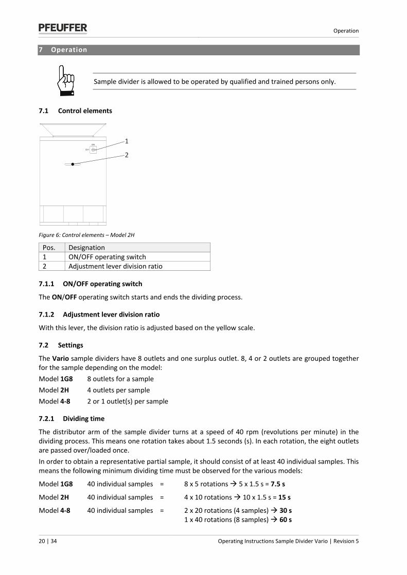
Figure 6: Control elements – Model 2H
Pos. Designation 1 ON/OFF operating switch 2 Adjustment lever division ratio
7.1.1 ON/OFF operating switch
The ON/OFF operating switch starts and ends the dividing process.
7.1.2 Adjustment lever division ratio
With this lever, the division ratio is adjusted based on the yellow scale.
7.2 Settings
The Vario sample dividers have 8 outlets and one surplus outlet. 8, 4 or 2 outlets are grouped together for the sample depending on the model: Model 1G8 8 outlets for a sample Model 2H 4 outlets per sample Model 4-8 2 or 1 outlet(s) per sample
7.2.1 Dividing time
The distributor arm of the sample divider turns at a speed of 40 rpm (revolutions per minute) in the dividing process. This means one rotation takes about 1.5 seconds (s). In each rotation, the eight outlets are passed over/loaded once. In order to obtain a representative partial sample, it should consist of at least 40 individual samples. This means the following minimum dividing time must be observed for the various models:
Model 1G8 40 individual samples = 8 x 5 rotations 5 x 1.5 s = 7.5 s
Model 2H 40 individual samples = 4 x 10 rotations 10 x 1.5 s = 15 s
Model 4-8 40 individual samples = 2 x 20 rotations (4 samples) 30 s 1 x 40 rotations (8 samples) 60 s
1
2
ON
OFF
Operation
Revision 5 | Operating Instructions Sample Divider Vario 21 | 34
The Pfeuffer GmbH recommends a dividing time of at least 20 seconds.
The time taken for each product to pass through can be influenced by the funnel outlet. The following accessories are available for this:
Pass-through time depending on the product Standard funnel Ø 48 mm approx. 12 kg/min Funnel Ø 30 mm: approx. 8 kg/min Insert for funnel passage Ø 25 mm approx. 4 kg/min Insert for funnel passage Ø 20 mm approx. 2 kg/min
For the article numbers of the inserts to reduce the outlets on the funnel with Ø 30 mm, refer to chapter 11.
7.2.2 Circumferential velocity
The distributor arm turns at a speed of 40 rpm in the dividing process. There is no provision for adjusting the speed.
7.2.3 Scale
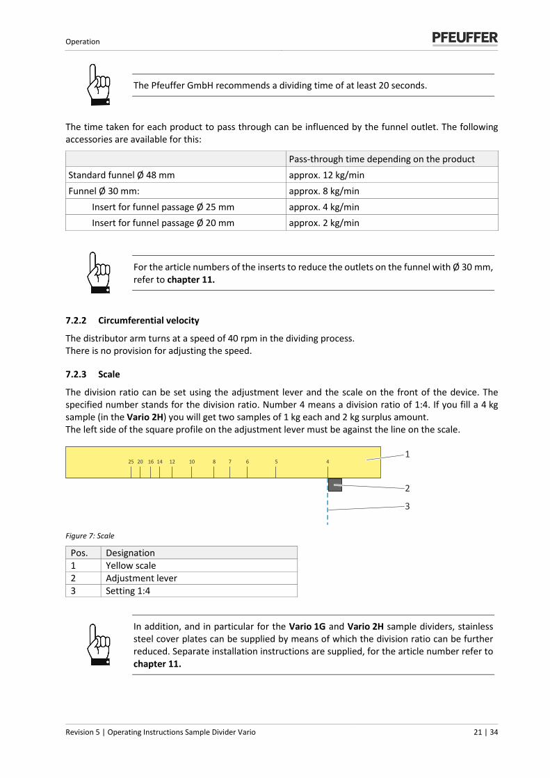
The division ratio can be set using the adjustment lever and the scale on the front of the device. The specified number stands for the division ratio. Number 4 means a division ratio of 1:4. If you fill a 4 kg sample (in the Vario 2H) you will get two samples of 1 kg each and 2 kg surplus amount. The left side of the square profile on the adjustment lever must be against the line on the scale.
Figure 7: Scale
Pos. Designation 1 Yellow scale 2 Adjustment lever 3 Setting 1:4
In addition, and in particular for the Vario 1G and Vario 2H sample dividers, stainless steel cover plates can be supplied by means of which the division ratio can be further reduced. Separate installation instructions are supplied, for the article number refer to chapter 11.
25 20 16 14 12 10 8 7 6 5 41
2
3
Operation
22 | 34 Operating Instructions Sample Divider Vario | Revision 5
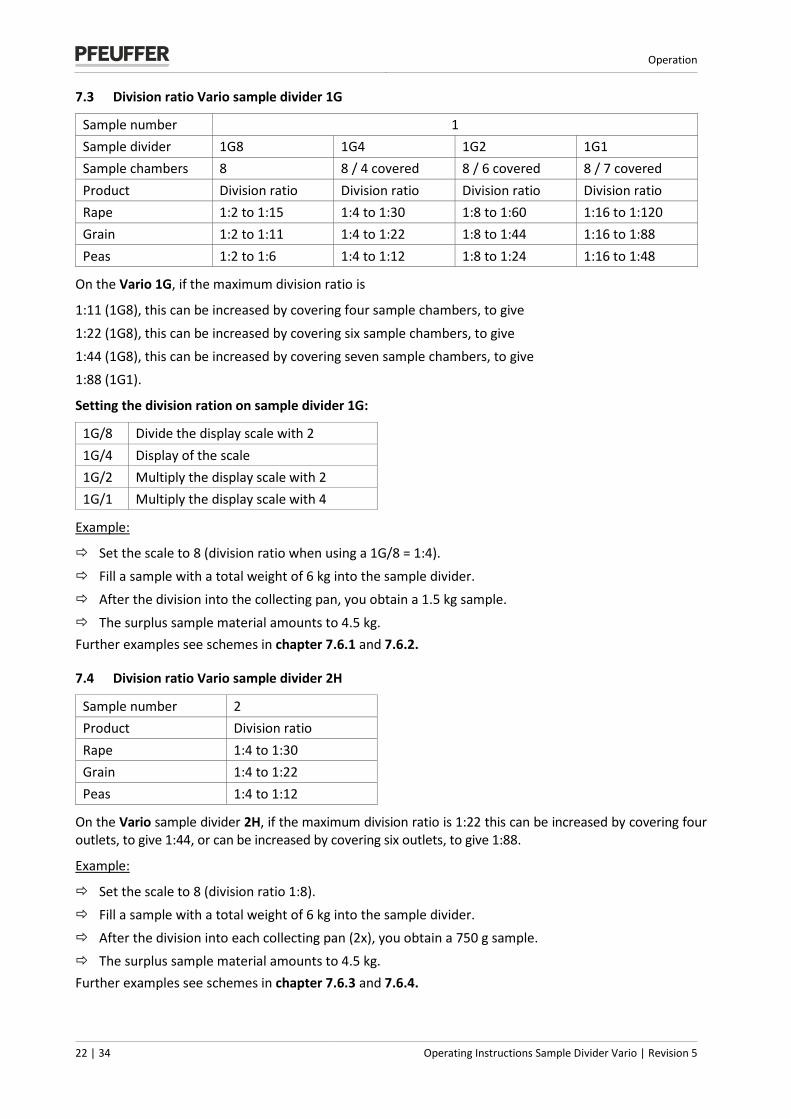
7.3 Division ratio Vario sample divider 1G
Sample number 1 Sample divider 1G8 1G4 1G2 1G1 Sample chambers 8 8 / 4 covered 8 / 6 covered 8 / 7 covered Product Division ratio Division ratio Division ratio Division ratio Rape 1:2 to 1:15 1:4 to 1:30 1:8 to 1:60 1:16 to 1:120 Grain 1:2 to 1:11 1:4 to 1:22 1:8 to 1:44 1:16 to 1:88 Peas 1:2 to 1:6 1:4 to 1:12 1:8 to 1:24 1:16 to 1:48
On the Vario 1G, if the maximum division ratio is
1:11 (1G8), this can be increased by covering four sample chambers, to give
1:22 (1G8), this can be increased by covering six sample chambers, to give 1:44 (1G8), this can be increased by covering seven sample chambers, to give 1:88 (1G1).
Setting the division ration on sample divider 1G:
1G/8 Divide the display scale with 2 1G/4 Display of the scale 1G/2 Multiply the display scale with 2 1G/1 Multiply the display scale with 4
Example:
Set the scale to 8 (division ratio when using a 1G/8 = 1:4). Fill a sample with a total weight of 6 kg into the sample divider. After the division into the collecting pan, you obtain a 1.5 kg sample.
The surplus sample material amounts to 4.5 kg. Further examples see schemes in chapter 7.6.1 and 7.6.2.
7.4 Division ratio Vario sample divider 2H
Sample number 2 Product Division ratio Rape 1:4 to 1:30 Grain 1:4 to 1:22 Peas 1:4 to 1:12
On the Vario sample divider 2H, if the maximum division ratio is 1:22 this can be increased by covering four outlets, to give 1:44, or can be increased by covering six outlets, to give 1:88.
Example:
Set the scale to 8 (division ratio 1:8). Fill a sample with a total weight of 6 kg into the sample divider. After the division into each collecting pan (2x), you obtain a 750 g sample. The surplus sample material amounts to 4.5 kg. Further examples see schemes in chapter 7.6.3 and 7.6.4.
Operation
Revision 5 | Operating Instructions Sample Divider Vario 23 | 34
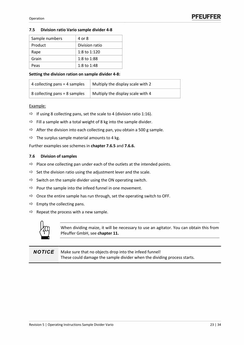
7.5 Division ratio Vario sample divider 4-8
Sample numbers 4 or 8 Product Division ratio Rape 1:8 to 1:120 Grain 1:8 to 1:88 Peas 1:8 to 1:48
Setting the division ration on sample divider 4-8:
4 collecting pans = 4 samples Multiply the display scale with 2
8 collecting pans = 8 samples Multiply the display scale with 4
Example:
If using 8 collecting pans, set the scale to 4 (division ratio 1:16).
Fill a sample with a total weight of 8 kg into the sample divider.
After the division into each collecting pan, you obtain a 500 g sample.
The surplus sample material amounts to 4 kg.
Further examples see schemes in chapter 7.6.5 and 7.6.6.
7.6 Division of samples
Place one collecting pan under each of the outlets at the intended points.
Set the division ratio using the adjustment lever and the scale.
Switch on the sample divider using the ON operating switch.
Pour the sample into the infeed funnel in one movement.
Once the entire sample has run through, set the operating switch to OFF.
Empty the collecting pans.
Repeat the process with a new sample.
When dividing maize, it will be necessary to use an agitator. You can obtain this from Pfeuffer GmbH, see chapter 11.
NOTICE Make sure that no objects drop into the infeed funnel! These could damage the sample divider when the dividing process starts.
Operation
24 | 34 Operating Instructions Sample Divider Vario | Revision 5
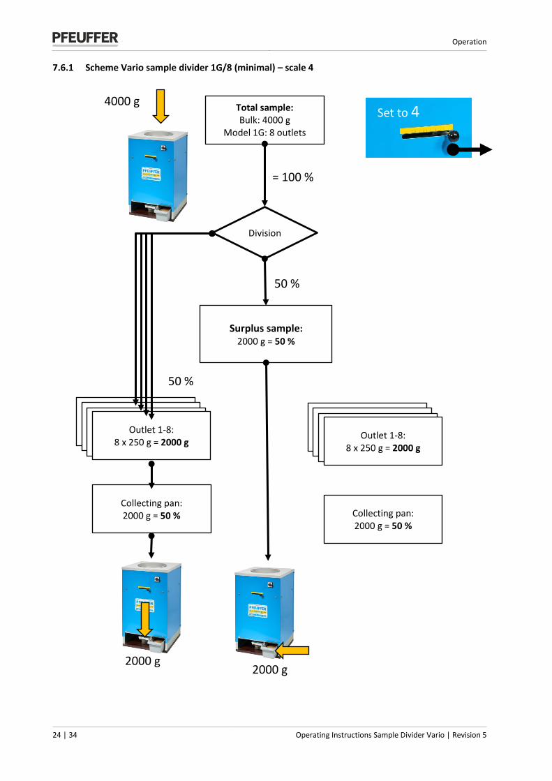
7.6.1 Scheme Vario sample divider 1G/8 (minimal) – scale 4
Total sample: Bulk: 4000 g
Model 1G: 8 outlets
Division
Surplus sample: 2000 g = 50 %
50 %
= 100 %
50 %
Collecting pan: 2000 g = 50 %
Öffnung 1: Teilungsverhältnis 1:4
250g = 80,3%
Öffnung 1: Teilungsverhältnis 1:4
250g = 80,3%
Öffnung 1: Teilungsverhältnis 1:4
250g = 80,3% Outlet 1-8:
8 x 250 g = 2000 g
2000 g 2000 g
4000 g
Set to 4
Öffnung 1: Teilungsverhältnis 1:4
250g = 80,3%
Öffnung 1: Teilungsverhältnis 1:4
250g = 80,3%
Öffnung 1: Teilungsverhältnis 1:4
250g = 80,3% Outlet 1-8:
8 x 250 g = 2000 g
Collecting pan: 2000 g = 50 %
Operation
Revision 5 | Operating Instructions Sample Divider Vario 25 | 34
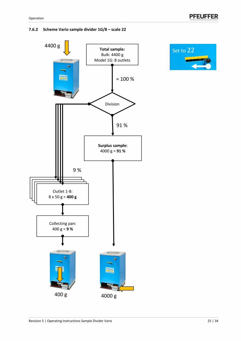
7.6.2 Scheme Vario sample divider 1G/8 – scale 22
Total sample: Bulk: 4400 g
Model 1G: 8 outlets
Division
Surplus sample: 4000 g = 91 %
9 %
= 100 %
91 %
4000 g 400 g
4400 g
Set to 22
Öffnung 1: Teilungsverhältnis 1:4
250g = 80,3%
Öffnung 1: Teilungsverhältnis 1:4
250g = 80,3%
Öffnung 1: Teilungsverhältnis 1:4
250g = 80,3% Outlet 1-8:
8 x 50 g = 400 g
Collecting pan: 400 g = 9 %

Operation
26 | 34 Operating Instructions Sample Divider Vario | Revision 5
7.6.3 Scheme Vario sample divider 2H (minimal) – scale 4
Total sample: bulk: 4000 g
Model 2H: 8 outlets
Division
Surplus sample: 2000 g = 50 %
25 %
= 100 %
50 %
Öffnung 1: Teilungsverhältnis 1:4
250g = 80,3%
Öffnung 1: Teilungsverhältnis 1:4
250g = 80,3%
Öffnung 1: Teilungsverhältnis 1:4
250g = 80,3% Outlet 1,3,5,7:
4 x 250 g = 1000 g
Collecting pan 1: 1000 g = 25 %
Collecting pan 2: 1000 g = 25 %
25 %
Öffnung 1: Teilungsverhältnis 1:4
250g = 80,3%
Öffnung 1: Teilungsverhältnis 1:4
250g = 80,3%
Öffnung 1: Teilungsverhältnis 1:4
250g = 80,3% Outlet 2,4,6,8:
4 x 250 g = 1000 g
1000 g 2000 g 1000 g
4000 g
Set to 4

Operation
Revision 5 | Operating Instructions Sample Divider Vario 27 | 34
7.6.4 Scheme Vario sample divider 2H – scale 22
Total sample: Bulk: 4000 g
Model 2H: 8 openings
Division
Surplus sample: 3636 g = 91 %
4,5 %
= 100 %
Öffnung 1: Teilungsverhältnis 1:4
250g = 80,3%
Öffnung 1: Teilungsverhältnis 1:4
250g = 80,3%
Öffnung 1: Teilungsverhältnis 1:4
250g = 80,3% Outlet 1,3,5,7:
4 x 45,25 g = 182 g
Collecting pan 1: 182 g = 4,5 %
Collecting pan 2: 182 g = 4,5 %
4,5 %
Öffnung 1: Teilungsverhältnis 1:4
250g = 80,3%
Öffnung 1: Teilungsverhältnis 1:4
250g = 80,3%
Öffnung 1: Teilungsverhältnis 1:4
250g = 80,3% Outlet 2,4,6,8:
4 x 45,25 g = 182 g
4000 g
91 %
Set to 22
182 g 3636 g 182 g
Operation
28 | 34 Operating Instructions Sample Divider Vario | Revision 5
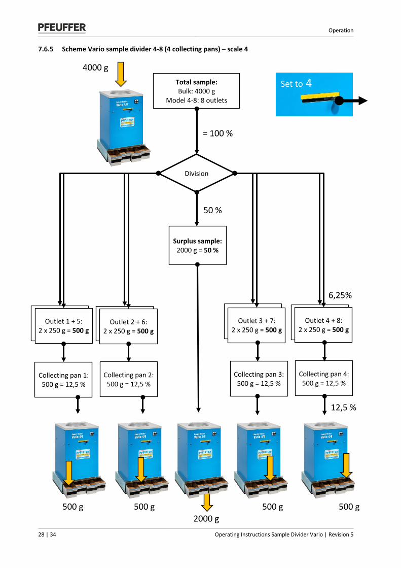
7.6.5 Scheme Vario sample divider 4-8 (4 collecting pans) – scale 4
Total sample: Bulk: 4000 g
Model 4-8: 8 outlets
Division
Surplus sample: 2000 g = 50 %
12,5 %
= 100 %
50 %
Outlet 1 + 5: 2 x 250 g = 500 g
Outlet 2 + 6: 2 x 250 g = 500 g
Collecting pan 1: 500 g = 12,5 %
Outlet 3 + 7: 2 x 250 g = 500 g
Outlet 4 + 8: 2 x 250 g = 500 g
4000 g
Collecting pan 2: 500 g = 12,5 %
Collecting pan 3: 500 g = 12,5 %
Collecting pan 4: 500 g = 12,5 %
6,25%
500 g
2000 g
500 g 500 g 500 g
Set to 4
Operation
Revision 5 | Operating Instructions Sample Divider Vario 29 | 34
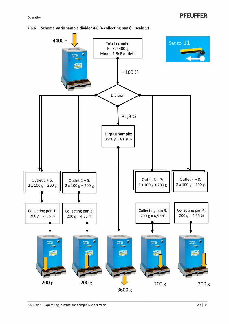
7.6.6 Scheme Vario sample divider 4-8 (4 collecting pans) – scale 11
Total sample: Bulk: 4400 g
Model 4-8: 8 outlets
Division
Surplus sample: 3600 g = 81,8 %
= 100 %
81,8 %
Outlet 1 + 5: 2 x 100 g = 200 g
Outlet 2 + 6: 2 x 100 g = 200 g
Collecting pan 1: 200 g = 4,55 %
3600 g
4400 g
Outlet 3 + 7: 2 x 100 g = 200 g
Outlet 4 + 8: 2 x 100 g = 200 g
Collecting pan 3: 200 g = 4,55 %
Collecting pan 4: 200 g = 4,55 %
200 g 200 g 200 g 200 g
Set to 11
Collecting pan 2: 200 g = 4,55 %

Maintenance and cleaning
30 | 34 Operating Instructions Sample Divider Vario | Revision 5
8 Maintenance and cleaning
The chapter Maintenance and cleaning is intended for skilled personnel only.
In order to guarantee a failure-free operation of the sample divider, it is absolutely necessary that the machine is regularly cleaned and maintained.
DANGER
Touching live parts can be fatal! It is essential to comply with the switch-off procedure before cleaning, maintenance or repair work! (see chapter 2.9).
The times for carrying out cleaning and maintenance work are based on one-shift working (8 hour/day, 22 days/month, 12 months/year).
d = Daily ¼ y = Every three months w = Weekly ½ y = Every six months m = Monthly y = Every year
8.1 Cleaning
NOTICE Do not use any sharp objects or tools for cleaning. Only use objects that are expressly intended for this purpose. During all work that is required, wear personal protective equipment according to the company health and safety regulations During cleaning, make sure that no water, steam or dust can penetrate the electronics area.
Motor
Excessive dust deposit on the motor can lead to overheating and failure.
Clean the motor with a dry cloth and / or compressed air.
8.2 Inspection interval and function test
Sub-assembly Interval in one-shift working
Normal function tests: w m ¼ y ½ y y
Buttons and switches X
Mains isolator (plug/socket combination) X
Markings and warnings present and legible (via visual inspection) X
Check if wires are tight X
Setting values at the circuit breaker X
Maintenance and cleaning
Revision 5 | Operating Instructions Sample Divider Vario 31 | 34
Sub-assembly Interval in one-shift working
Normal function tests: w m ¼ y ½ y y
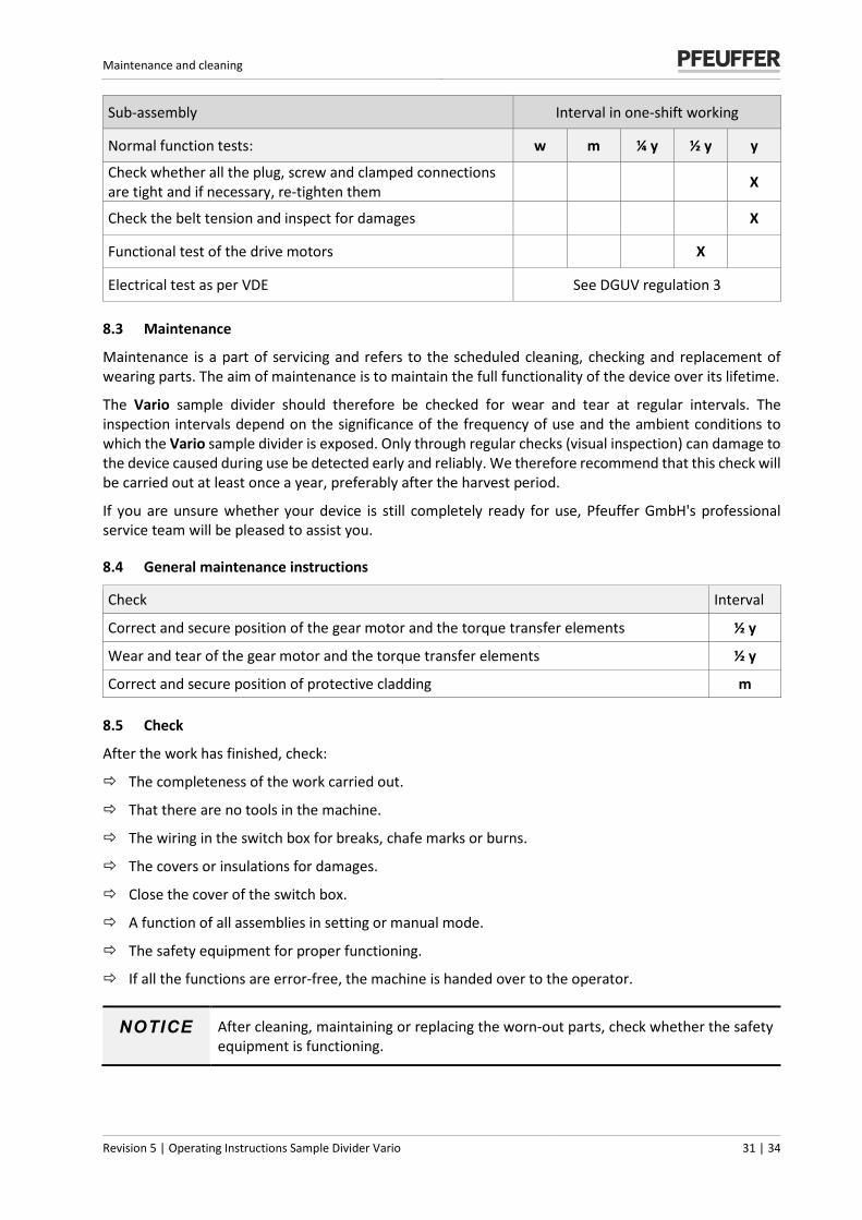
Check whether all the plug, screw and clamped connections are tight and if necessary, re-tighten them X
Check the belt tension and inspect for damages X
Functional test of the drive motors X
Electrical test as per VDE See DGUV regulation 3
8.3 Maintenance
Maintenance is a part of servicing and refers to the scheduled cleaning, checking and replacement of wearing parts. The aim of maintenance is to maintain the full functionality of the device over its lifetime.
The Vario sample divider should therefore be checked for wear and tear at regular intervals. The inspection intervals depend on the significance of the frequency of use and the ambient conditions to which the Vario sample divider is exposed. Only through regular checks (visual inspection) can damage to the device caused during use be detected early and reliably. We therefore recommend that this check will be carried out at least once a year, preferably after the harvest period.
If you are unsure whether your device is still completely ready for use, Pfeuffer GmbH's professional service team will be pleased to assist you.
8.4 General maintenance instructions
Check Interval
Correct and secure position of the gear motor and the torque transfer elements ½ y
Wear and tear of the gear motor and the torque transfer elements ½ y
Correct and secure position of protective cladding m
8.5 Check
After the work has finished, check:
The completeness of the work carried out.
That there are no tools in the machine.
The wiring in the switch box for breaks, chafe marks or burns.
The covers or insulations for damages.
Close the cover of the switch box.
A function of all assemblies in setting or manual mode.
The safety equipment for proper functioning.
If all the functions are error-free, the machine is handed over to the operator.
NOTICE After cleaning, maintaining or replacing the worn-out parts, check whether the safety equipment is functioning.
Malfunctions – causes and rectification
32 | 34 Operating Instructions Sample Divider Vario | Revision 5
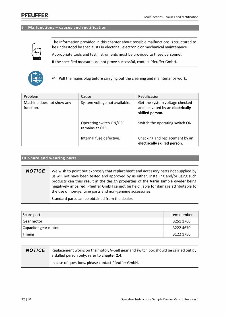
9 Malfunctions – causes and rectification
The information provided in this chapter about possible malfunctions is structured to be understood by specialists in electrical, electronic or mechanical maintenance.
Appropriate tools and test instruments must be provided to these personnel.
If the specified measures do not prove successful, contact Pfeuffer GmbH.
Pull the mains plug before carrying out the cleaning and maintenance work.
Problem Cause Rectification Machine does not show any function.
System voltage not available. Operating switch ON/OFF remains at OFF. Internal fuse defective.
Get the system voltage checked and activated by an electrically skilled person. Switch the operating switch ON. Checking and replacement by an electrically skilled person.
10 Spare and wearing parts
NOTICE We wish to point out expressly that replacement and accessory parts not supplied by us will not have been tested and approved by us either. Installing and/or using such products can thus result in the design properties of the Vario sample divider being negatively impaired. Pfeuffer GmbH cannot be held liable for damage attributable to the use of non-genuine parts and non-genuine accessories.
Standard parts can be obtained from the dealer.
NOTICE Replacement works on the motor, V-belt gear and switch box should be carried out by a skilled person only; refer to chapter 2.4.
In case of questions, please contact Pfeuffer GmbH.
Spare part Item number Gear motor 3251 1760 Capacitor gear motor 3222 4670 Timing 3122 1750
Supplements and accessories
Revision 5 | Operating Instructions Sample Divider Vario 33 | 34
11 Supplements and accessories
Product Item number
Standard funnel Ø 48 mm 3331 0500
Extension funnel capacity up to 8 kg 3331 0510
Funnel Ø 30 mm (9 kg/min) 3331 0520
Insert for funnel passage Ø 25 mm 3332 0503
Insert for funnel passage Ø 20 mm 3332 0506
Insert for funnel passage Ø 16 mm 3332 0509
Insert for funnel passage Ø 12 mm 3332 0512
Hook-in plates (stainless steel) amending the division ratio 3331 0530
Collecting pan (PVC) 2 liter Dimensions with handle: 275x133x108 mm 3110 0050
Collecting pan (stainless steel) 2 liter Dimensions with handle: 275x133x108 mm 3351 0500
Collecting pan (stainless steel) 3,5 liter Dimensions with handle: 385x133x108 mm 3331 9015
Sample pan for flow (stainless steel) Dimensions with handle: 345x137x108 mm 1740 0081
Side funnel for model Vario 2H 3321 4020
Agitator for non-free-flowing products 1745 0065
Only for sample divider 4-8:
Collecting pan (stainless steel) 2 liter Dimensions with handle: 211x133x108 mm 3331 9010
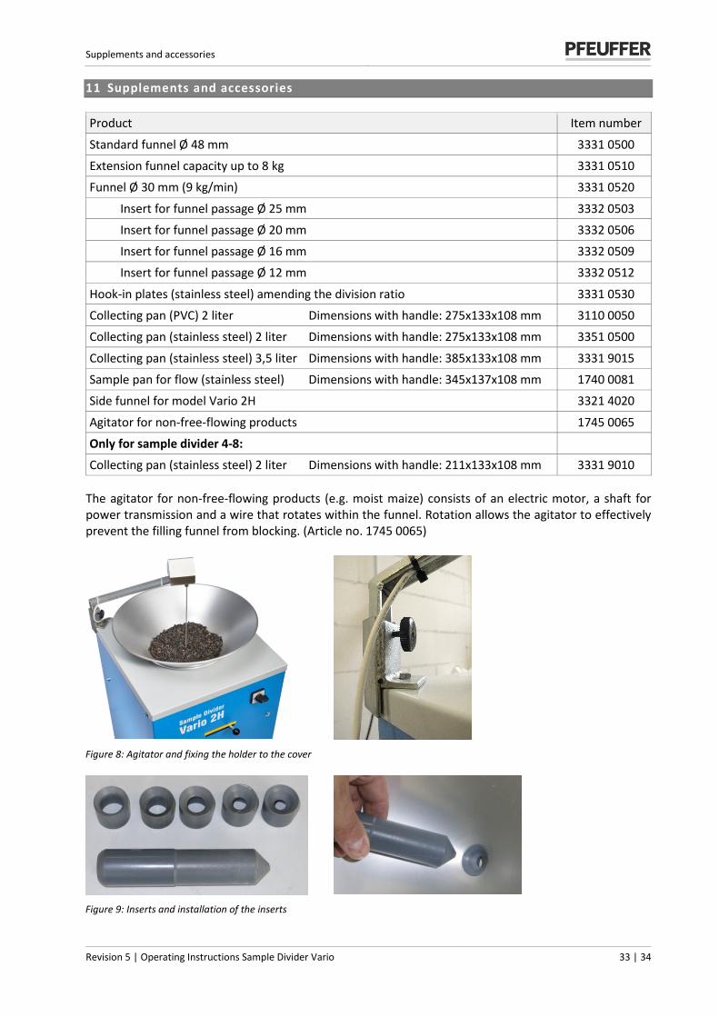
The agitator for non-free-flowing products (e.g. moist maize) consists of an electric motor, a shaft for power transmission and a wire that rotates within the funnel. Rotation allows the agitator to effectively prevent the filling funnel from blocking. (Article no. 1745 0065)
Figure 8: Agitator and fixing the holder to the cover
Figure 9: Inserts and installation of the inserts
Emergency
34 | 34 Operating Instructions Sample Divider Vario | Revision 5
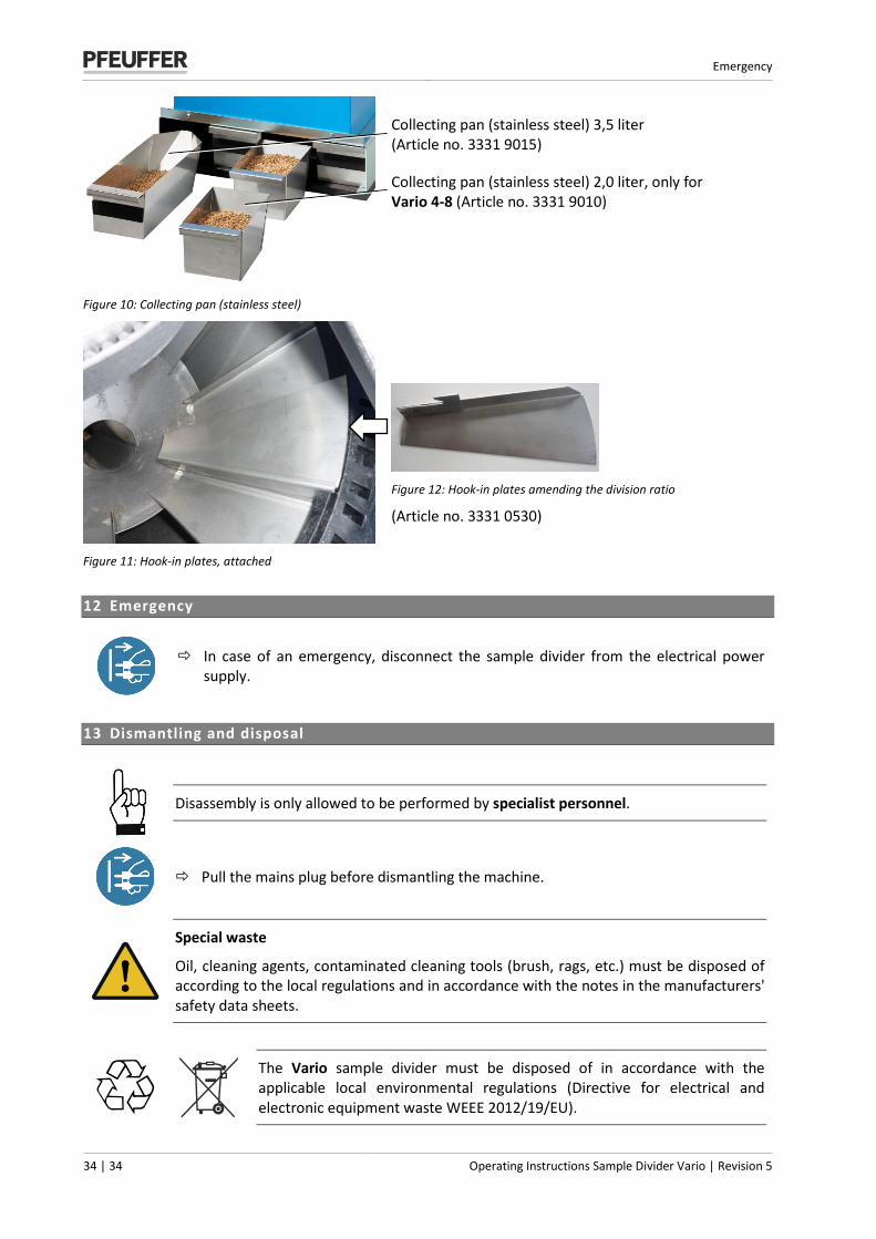
Figure 10: Collecting pan (stainless steel)
Collecting pan (stainless steel) 3,5 liter (Article no. 3331 9015)
Collecting pan (stainless steel) 2,0 liter, only for Vario 4-8 (Article no. 3331 9010)
Figure 11: Hook-in plates, attached
Figure 12: Hook-in plates amending the division ratio
(Article no. 3331 0530)
12 Emergency
In case of an emergency, disconnect the sample divider from the electrical power supply.
13 Dismantling and disposal
Disassembly is only allowed to be performed by specialist personnel.
Pull the mains plug before dismantling the machine.
Special waste
Oil, cleaning agents, contaminated cleaning tools (brush, rags, etc.) must be disposed of according to the local regulations and in accordance with the notes in the manufacturers' safety data sheets.
The Vario sample divider must be disposed of in accordance with the applicable local environmental regulations (Directive for electrical and electronic equipment waste WEEE 2012/19/EU).