Pegelsonden 05 2003 - PFI FLOWTEKNIK
30
Pe els nd n / Lvl b g o e e e Pro es Auch mit Ex- und GL- Zulassung Also with Ex- and GL- Approval switch switch
Transcript of Pegelsonden 05 2003 - PFI FLOWTEKNIK

Pe els nd n / L v l bg o e e e Pro es
Auch mit
Ex- und GL-Zulassung
Also with
Ex- and GL-Approval
switchswitch

Tech
nisc
he Ä
nder
unge
n vo
rbeh
alte
n.B
arks
dale
Peg
elso
nden
05 /
03
PG
S-E
D 0
3/2
2
Aufbau und Funktion
Basiselemente der Pegelsonden sind Drucksensoren inEdelstahl- bzw. Kermikausführung.Die Messzellen verfügen über eine laserverschweissteTrennmembrane mit interner Ölvorlage.
Während der Messung erzeugt die über der Pegel-sonde liegende Flüssigkeitssäule einen Druck, derüber die Trennmembrane und die interne Ölvorlage aufdas Halbleitersensorelement übertragen wird.Eine Verstärkerelektronik versorgt den Sensor undwandelt das zur Füllhöhe proportionale Signal in eintemperaturkompensiertes Normausgangssignal(4...20 mA, 0...10 VDC). Das Nutzsignal wird dannüber ein Kabel an nachgeschaltete Auswerte- undAnzeigeeinheiten weitergeleitet.
Bei diesem Messprinzip spricht man auch von hydro-statischer Füllstandmessung.
Für jedes Medium eine Lösung
Mit den hydrostatischen Tauchsonden der BaureihenUPA2-LMP und UPA2-LMK können Füllstände zwischen60 cm und 200 m kontinuierlich gemessen werden.Durch die Auswahl bei den verwendeten Werkstoffenstehen auch für aggressive Medien Lösungen zurVerfügung.
Nach Abnehmen der Schutzkappe ist selbst der Ein-satz in höherviskosen Schlämmen möglich. Auch einegeflanschte Ausführung ist lieferbar.Der elektrische Anschluss erfolgt über ein PVC-oderPUR-Kabel. Durch eine Patentlösung kann das Kabel-teil von der eigentlichen Sonde getrennt werden. Dieserleichtert die Handhabung, Wartung und Lagerhaltung.Die Kabelteile sind in unterschiedlichen Ausführungen(Kabel bzw. Kabelschutz mit Hart- oder Wellrohr)lieferbar.
Überdurchschnittliche messtechnische Eigenschaftenwie 0,35% FS IEC 770 und Langzeitstabilität sindselbstverständlich serienmäßig. Die Ausführungen inEdelstahl sind auch in II 1 G EEx ia IIC T4 lieferbar.
Für Sonderanwendungen bieten wir intelligente Pegel-sonden mit serieller Schnittstelle, SMART-Technologieund Dataloggerfunktion.
Construction and function
The basic elements of the level indicators are Stainless Steelor ceramic pressure sensors.These cells have a laser-welded separating membrane filledwith an oil medium.
During a measurment, the column of liquid on top of the levelindicator creates pressure which is transferred via the sepa-rating membrane and oil medium to the semi-conductor sen-sor.
The sensor is equipped with amplifying electronics whichtranslate the level output into a temperature compensatednorm output (4...20 mA, 0...10 VDC). The output is then trans-mitted by a connecting line to the reader/display unit.
This process is also referred to as hydrostatic level measure-ment.
Designed for various media
With the hydrostatic submersion probes of the UPA2-LMP andUPA-LMK series, tank levels of between 60 cm and 200 mcan be continuously measured. There are various materialsavailable, even for aggressive media.
After removing the protecting cover, the probes can be usedeven in highly viscous media such as silt and sludge deposits.Also a flanged version is available. The electric connection tothe probe is by a PVC or PUR cable. For easy handling, main-tenance and storage the cable can be disconnected from theprobe. Cables are available in various designs (cables or pro-tective covering with hard or corrugated tubing).
Above-average tolerances, e.g. 0.35 % FS IEC 770, and long-term stability are standard features of the line. The stainlesssteel versions are also available as II 1 G EEx ia IIC T4.
For special applications we can provide probes with featuressuch as serial interface, SMART technology and data loggingfunctions.
Pegelsonden

Spe
cific
atio
ns a
re s
ubje
ct
to c
hang
es w
ithou
t no
tice.
Bar
ksda
le L
evel
Pro
bes
05 /
03
PG
S-E
D 0
3/2
3
Die Schlanke
Vor allem im Bereich des Brunnenbaues kommtdie Sonde UPA2-LMP307 mit Edelstahlgehäusezum Einsatz.Sie ist fest mit dem Kabel verbunden. Ihr Durch-messer beträgt 27 mm, die Messbereiche liegenzwischen 1 mWS und 160 mWsOption: Ausführung in II 1 G EEx ia IIC T4,
Seite 4/5
Die Trennbare
Für Applikationen auch in höherviskosen Medienund zur Messung kleiner Füllhöhen ist SondeUPA2-LMK358 ideal geeignet.
Seite 6/7
Die Widerstandsfähige
Mit ihrer Keramik-Druckmesszelle und demKunststoffgehäuse ist die SondeUPA2-LMK858 konzipiert für den Einsatz inaggresiven Medien wie Säuren und Laugen.
Seite 8/9
Die Zugelassene
Speziell für den Einsatz in der Schiffahrtstechnikwurde die Sonde UPA2-LMK457-GL entwickelt.Die Sonde ist nach den Richtlinien des Germa-nischen Lloyd geprüft und zertifiziert.
Seite 10/11/12/13
Ebenfalls für den Einsatz in der Schiffahrtstechnikwurde der einschraubbare FüllstandtransmitterUPA2-DMP457-GL konzipiert.
Seite 14/15
Einsatzbereiche
Tiefenmessungen in BrunnenGrundwasserpegelmessungenFüllstandüberwachungen in offenen Behälternauch mit geringen FüllhöhenUmwelttechnik: Klärwerke, WasseraufbereitungProzesstechnik: Chemische Anlagen, PharmazieSchiffahrtstechnik: Bilgentanküberwachung
The small one
With its 27 mm diameter, the UPA2-LMP307 probe is idealfor well-drilling and construction applications.The probe is permanently secured to the cable. The mea-suring range is from 1 mWC to 160 mWC. The housingmaterial is stainless steel.Option: II 1 G EEx ia CII T4.
Page 16/17
The separable one
The UPA2-LMK358 probe is specially designed for use inviscous media and for measuring low filling levels. Thecable can be easily separated from the probe, which facili-tates maintenance and storage.
Page 18/19
The resistant one
Ceramic pressure elements in combination with a housingmade of plastic makes the UPA2-LMK858 probe espe-cially suitable for use in aggressive media such as acidsand caustic solutions.
Page 20/21
The approved one
The UPA2-LMK457-GL probe is specially designed forapplications in the shipping industry and is approved andcertified according to Germanischer Lloyd guidelines.
Page 22/23/24/25
Also designed for applications in the shipping industry Is thelevel transmitter type UPA2-DMP457-GL.This type is available with a thread connection.
Page 26/27
Range of Application
Water levels in wellsGround water level measurementLevel indication in open tanks, even with low filling levelsEnvironmentaltechnology: Waste-water purification
water recycling plantsProcess industry: Chemical plants, pharmaceut. industryShipping industry: Bilge tank control
Pegelsonden
Level Probes
05 /
03
PG
S-E
D 0
3/2
Tech
nisc
he Ä
nder
unge
n vo
rbeh
alte
n.B
arks
dale
Peg
elso
nden
4
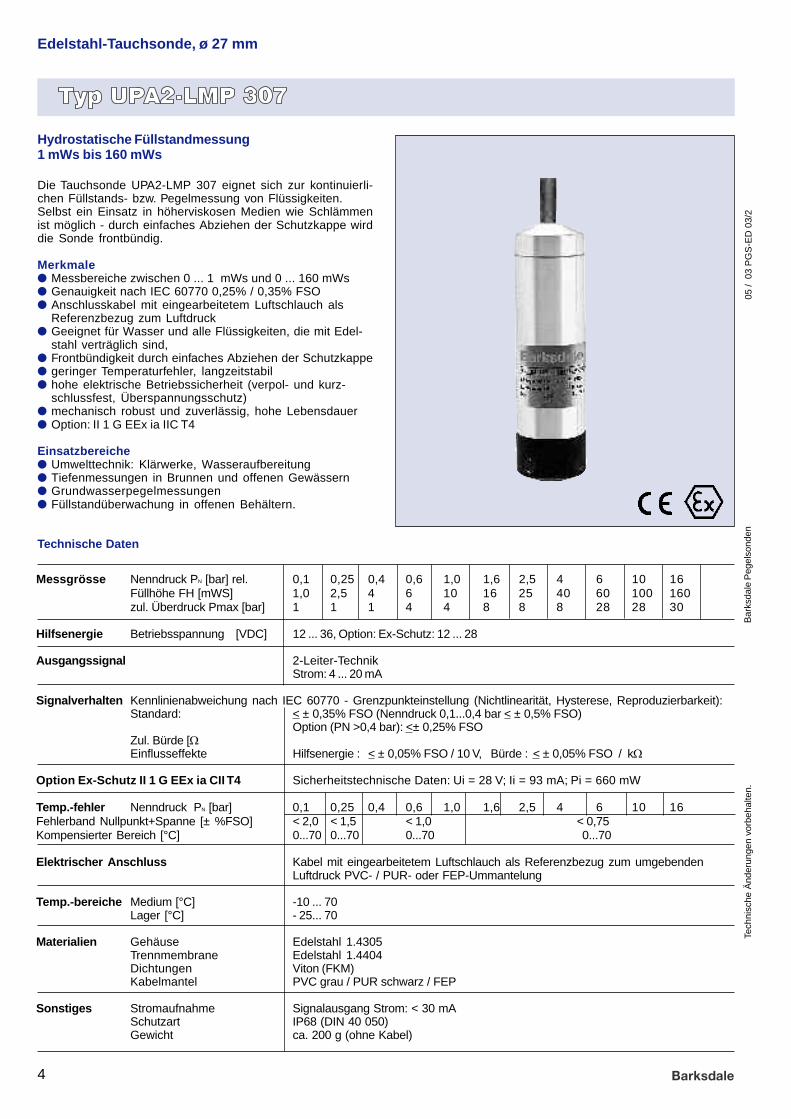
Messgrösse Nenndruck PN [bar] rel. 0,1 0,25 0,4 0,6 1,0 1,6 2,5 4 6 10 16Füllhöhe FH [mWS] 1,0 2,5 4 6 10 16 25 40 60 100 160zul. Überdruck Pmax [bar] 1 1 1 4 4 8 8 8 28 28 30
Hilfsenergie Betriebsspannung [VDC] 12 ... 36, Option: Ex-Schutz: 12 ... 28
Ausgangssignal 2-Leiter-TechnikStrom: 4 ... 20 mA
Signalverhalten Kennlinienabweichung nach IEC 60770 - Grenzpunkteinstellung (Nichtlinearität, Hysterese, Reproduzierbarkeit):Standard: < ± 0,35% FSO (Nenndruck 0,1...0,4 bar < ± 0,5% FSO)
Option (PN >0,4 bar): <± 0,25% FSOZul. Bürde [W] Strom 2-Leiter : [UB (V) - 12V] / 0,02 AEinflusseffekte Hilfsenergie : < ± 0,05% FSO / 10 V, Bürde : < ± 0,05% FSO / kW
Option Ex-Schutz II 1 G EEx ia CII T4 Sicherheitstechnische Daten: Ui = 28 V; Ii = 93 mA; Pi = 660 mW
Temp.-fehler Nenndruck PN [bar] 0,1 0,25 0,4 0,6 1,0 1,6 2,5 4 6 10 16Fehlerband Nullpunkt+Spanne [± %FSO] < 2,0 < 1,5 < 1,0 < 0,75Kompensierter Bereich [°C] 0...70 0...70 0...70 0...70
Elektrischer Anschluss Kabel mit eingearbeitetem Luftschlauch als Referenzbezug zum umgebendenLuftdruck PVC- / PUR- oder FEP-Ummantelung
Temp.-bereiche Medium [°C] -10 ... 70Lager [°C] - 25... 70
Materialien Gehäuse Edelstahl 1.4305Trennmembrane Edelstahl 1.4404Dichtungen Viton (FKM)Kabelmantel PVC grau / PUR schwarz / FEP
Sonstiges Stromaufnahme Signalausgang Strom: < 30 mASchutzart IP68 (DIN 40 050)Gewicht ca. 200 g (ohne Kabel)
Die Tauchsonde UPA2-LMP 307 eignet sich zur kontinuierli-chen Füllstands- bzw. Pegelmessung von Flüssigkeiten.Selbst ein Einsatz in höherviskosen Medien wie Schlämmenist möglich - durch einfaches Abziehen der Schutzkappe wirddie Sonde frontbündig.
Merkmalel Messbereiche zwischen 0 ... 1 mWs und 0 ... 160 mWsl Genauigkeit nach IEC 60770 0,25% / 0,35% FSOl Anschlusskabel mit eingearbeitetem Luftschlauch als
Referenzbezug zum Luftdruckl Geeignet für Wasser und alle Flüssigkeiten, die mit Edel-
stahl verträglich sind,l Frontbündigkeit durch einfaches Abziehen der Schutzkappel geringer Temperaturfehler, langzeitstabill hohe elektrische Betriebssicherheit (verpol- und kurz-
schlussfest, Überspannungsschutz)l mechanisch robust und zuverlässig, hohe Lebensdauerl Option: II 1 G EEx ia IIC T4
Einsatzbereichel Umwelttechnik: Klärwerke, Wasseraufbereitungl Tiefenmessungen in Brunnen und offenen Gewässernl Grundwasserpegelmessungenl Füllstandüberwachung in offenen Behältern.
Technische Daten
Edelstahl-Tauchsonde, ø 27 mm
Hydrostatische Füllstandmessung1 mWs bis 160 mWs

05 /
03
PG
S-E
D 0
3/2
Spe
cific
atio
ns a
re s
ubje
ct
to c
hang
es w
ithou
t no
tice.
Bar
ksda
le L
evel
Pro
bes
5
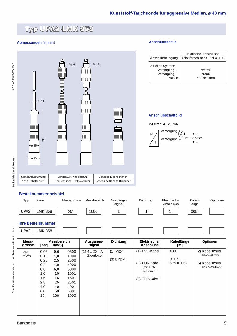
Bestellnummernbeispiel
Abmessungen (in mm)
(1) 4... 20 mAZweileiter
(E) 4... 20 mAZweileiterEx-SchutzII 1 GEExia IIC T4
barmWs
(1) PVC-Kabel
(2) PUR-Kabel
(3) FEP-Kabel
0,1 1,0 10000,25 2,5 25000,4 4,0 40000,6 6,0 60001,0 10 10011,6 16 16012,5 25 25014,0 40 40016,0 60 600110 100 100216 160 1602
(3) 0,35% Standard
(5) 0,5% für(PN < 0,4 bar)
(2) 0,25% Option für(PN > 0,4 bar)
Messbereich[bar] [mWS]
Mess-grösse
Ausgangs-signal
Kabellänge[m]
Genauigkeit
MessbereichMessgrösse Ausgangs-signal
ElektrischerAnschluss
Genauig-keit
Typ Serie
bar 1000 1 5 1
Ihre Bestellnummer
ElektrischerAnschluss
XXX
(z. B.: 5 m = 005)
Kabel-länge
005
UPA2 LMP 307
UPA2 LMP 307
Edelstahl-Tauchsonde, ø 27 mm
Anschlusstabelle
Elektrische AnschlüsseAnschlussbelegung Kabelfarben nach DIN 47100
2-Leiter-System:Versorgung + weissVersorgung – braun
Masse Kabelschirm
157122
Schutzkappe abnehmbar - ergibt Frontbündigkeit
Versorgung +
Versorgung – 12...36 VDC
2-Leiter: 4...20 mA
Anschlussschaltbildø 27 ø 27
ø 7,4 ø 7,4
Option: Ex-Schutz

05 /
03
PG
S-E
D 0
3/2
Tech
nisc
he Ä
nder
unge
n vo
rbeh
alte
n.B
arks
dale
Peg
elso
nden
6
Messgrösse Nenndruck PN [bar] rel. 0,06 0,1 0,25 0,4 0,6 1 1,6 2,5 4 6 10 20Füllhöhe FH [mWS] 0,6 1,0 2,5 4 6 10 16 20 40 60 100 200zul. Überdruck Pmax [bar] 2 2 2 4 4 7 7 15 25 25 40 60
Hilfsenergie Betriebsspannung [VDC]: 12 ... 36, Option: Ex-Schutz: 12 ... 28
Ausgangssignal 2-Leiter-Technik, Strom: 4 ... 20 mA
Signalverhalten Kennlinienabweichung nach IEC 60770 - Grenzpunkteinstellung (Nichtlinearität, Hysterese, Reproduzierbarkeit)Standard: < ± 0,35% FSOZul. Bürde [W] Strom 2-Leiter: [ UB (V) - 12V] / 0,02 AEinflusseffekte Hilfsenergie: < ± 0,05% FSO / 10 V Bürde : < ± 0,05% FSO / kW
Option Ex-Schutz II 1 G EEx ia CII T4 Sicherheitstechnische Daten: Ui = 28 V; Ii = 93 mA; Pi = 660 mW
Temperaturfehler Fehlerband für Nullpunkt und Spanne im kompensierten Bereich10 ... 70°C : < ± 1 % FSO
Elektrischer Anschluss Kabel mit eingearbeitetem Luftschlauch als Referenzbezug zum umgebendenLuftdruck, PVC- / PUR- oder FEP-Ummantelung
Temp.-bereiche Medium [°C] -10 ... 70Lager [°C] -25 ... 70
Kabelschutz Standard ohne KabelschutzSonderausführung für Montage mit Edelstahlrohr (vorbereitet)
Materialien Gehäuse 1.4571Trennmembrane Keramik Al2O3 96 % / Andere: auf AnfrageDichtungen Viton (FKM) / Option: EPDMKabelmantel PVC grau / PUR schwarz / FEP
Sonstiges Stromaufnahme < 30 mASchutzart IP68 (DIN 40 050)Gewicht ca. 400 g (ohne Kabel)
Montagezubehör Montageflansch aus Hart-PVC grau DN10/PN10Montageverschraubung Edelstahl
Technische Daten
Edelstahl-Tauchsonde, ø 40 mm
Kapazitiver KeramiksensorHydrostatische Füllstandmessung0,6 mWs bis 200 mWs
Die Tauchsonde UPA2-LMK 358 wurde für die kontinuierlicheFüllstand- bzw. Pegelmessung vor allem von kleinen Füllhöhenentwickelt. Diese spezielle Eignung ist auf eine besonders emp-findliche Keramik-Druckmeßzelle zurückzuführen.
Ein Einsatz in höherviskosen Medien wie Schlämmen ist durchgute Frontbündigkeit der Meßmembrane möglich.
Merkmalel Messbereiche zwischen 0... 0,6 mWs und 0... 200 mWsl Genauigkeit nach IEC 60770 0,35% FSOl Sonde und Kabelteil mittels Steckverbinder trennbarl Kabelschutz mit Edelstahlrohr möglichl Geeignet für Wasser und alle Flüssigkeiten, die mit
Edelstahl verträglich sindl Frontbündige Membranel geringer Temperaturfehler, langzeitstabill verpol- und kurzschlussfest, Überspannungsschutzl mechanisch robust und zuverlässig, hohe Lebensdauerl Option: II 1 G EEx ia IIC T4
Einsatzbereichel Füllstandüberwachung in offenen Behältern mit geringen
Füllhöhenl Tiefenmessungen in Brunnen und offenen Gewässernl Grundwasserpegelmessungenl Klärwerke, Wasseraufbereitung, Chemie, Pharmazie

05 /
03
PG
S-E
D 0
3/2
Spe
cific
atio
ns a
re s
ubje
ct
to c
hang
es w
ithou
t no
tice.
Bar
ksda
le L
evel
Pro
bes
7
Edelstahl-Tauchsonde, ø 40 mm
Abmessungen (in mm)
Bestellnummernbeispiel
(1) 4... 20 mAZweileiter
(E) 4... 20 mAZweileiterEx-SchutzII 1 GEExia IIC T4
barmWs
0,06 0,6 06000,1 1,0 10000,25 2,5 25000,4 4,0 40000,6 6,0 60001,0 10 10011,6 16 16012,5 25 25014,0 40 40016,0 60 600110 100 100216 160 160220 200 2002
(1) Viton
(3) EPDM
Optionen Messbereich[bar] [mWS]
Mess-grösse
Ausgangs-signal
Kabellänge[m]
Dichtung
OptionenMessbereichMessgrösse Ausgangs-signal
ElektrischerAnschluss
DichtungTyp Serie
bar 1000 1 1 1
Ihre Bestellnummer
ElektrischerAnschluss
(6) Montage inEdelstahlrohr(vorbereitet)
XXX
(z. B.:5 m = 005)
Kabel-länge
005
UPA2 LMK 358
UPA2 LMK 358
(1) PVC-Kabel
(2) PUR-Kabel
(3) FEP-Kabel
Standardausführung Sonderausf. Kabelschutz Sonstige Eigenschaften
ohne Kabelschutz Edelstahlrohr Sonde und Kabelteil trennbar
Versorgung +
Versorgung – 12...36 VDC
2-Leiter: 4...20 mA
Anschlussschaltbild
Anschlusstabelle
Elektrische AnschlüsseAnschlußbelegung Kabelfarben nach DIN 47100
2-Leiter-System:Versorgung + weissyVersorgung – braun
Masse Kabelschirm
192
ø 40
ø35
ø 7,4

05 /
03
PG
S-E
D 0
3/2
Tech
nisc
he Ä
nder
unge
n vo
rbeh
alte
n.B
arks
dale
Peg
elso
nden
8
Messgrösse Nenndruck PN [bar] rel. 0,06 0,1 0,25 0,4 0,6 1 1,6 2,5 4 6 10Füllhöhe FH [mWS] 0,6 1,0 2,5 4 6 10 16 20 40 60 100zul. Überdruck Pmax [bar] 2 2 2 4 4 7 7 15 25 25 40
Hilfsenergie Betriebsspannung: [VDC] 12 ... 36
Ausgangssignal Standard : 2-Leiter-Technik, Strom: 4 ... 20 mA
Signalverhalten Kennlinienabweichung nach IEC 60770 - Grenzpunkteinst. (Nichtlinearität, Hysterese, Reproduzierbarkeit)Standard: < ± 0,35% FSOZul. Bürde [W] Strom 2-Leiter : [ UB (V) - 12V] / 0,02 AEinflußeffekte Hilfsenergie : < ± 0,05% FSO / 10 V Bürde : < ± 0,05% FSO / kW
Temperaturfehler Fehlerband für Nullpunkt und Spanne im kompensierten Bereich0 ... 70°C: < ± 1,0 % FSO
Elektrischer Anschluss Kabel mit eingearbeitetem Luftschlauch als Referenzbezug zum umgebendenLuftdruck PVC- / PUR- oder FEP-Ummantelung
Temp.-bereiche Medium [°C] 0 ... 50Lager [°C] -10... 50
Kabelschutz Standard ohne KabelschutzSonderausführungen PP-Wellrohr (flexibel), PVC-Rohr (starr)
Materialien Gehäuse PVC grauTrennmembrane Keramik Al2O3 96 % / Option: PTFE-FolieDichtungen Viton (FKM) / Option: EPDMKabelmantel PVC grau / PUR schwarz / FEP
Sonstiges Stromaufnahme Signalausgang Strom: < 30 mASchutzart IP68 (DIN 40 050)Gewicht ca. 400 g (ohne Kabel)
Montagezubehör Montageflansch: Hart-PVC grau DN10/PN10Montageverschraubung PVC
Technische Daten
Kunststoff-Tauchsonde für aggressive Medien, ø 40 mm
Die Tauchsonde UPA2-LMK 858 wurde für die kontinuierliche Füll-standsmessung von aggressiven Medien vor allem von kleinenFüllhöhen entwickelt. Durch die Verwendung von speziellen Kunst-stoffen ist diese Sonde besonders für den Einsatz in aggressivenMedien geeignet
Ein Einsatz in höherviskosen Medien wie Schlämmen ist durchgute Frontbündigkeit der Messmembrane möglich.
Merkmalel Messbereiche zwischen 0 ... 0,6 mWs und 0 ... 100 mWsl Genauigkeit nach IEC 60770 0,35% FSOl Sonde und Kabelteil mittels Steckverbinder trennbarl Kabelschutz mit PVC-Rohr oder PP-Wellrohr möglichl Geeignet für Wasser und alle Flüssigkeiten, die mit PVC
und Keramik Al2O3 verträglich sindl Frontbündige Membranel geringer Temperaturfehler, langzeitstabill verpol- und kurzschluß-fest, Überspannungsschutzl mechanisch robust und zuverlässig, hohe Lebensdauer
Einsatzbereichel Füllstandüberwachung in offenen Behältern mit geringen
Füllhöhenl Tiefenmessungen in Brunnen und offenen Gewässernl Grundwasserpegelmessungenl Klärwerke, Wasseraufbereitung, Chemie, Pharmazie.
Kapazitiver KeramiksensorHydrostatische Füllstandmessung1 mWs bis 10 mWs
05 /
03
PG
S-E
D 0
3/2
Spe
cific
atio
ns a
re s
ubje
ct
to c
hang
es w
ithou
t no
tice.
Bar
ksda
le L
evel
Pro
bes
9
Kunststoff-Tauchsonde für aggressive Medien, ø 40 mm
Abmessungen (in mm)
Bestellnummernbeispiel
(1) 4... 20 mAZweileiter
barmWs
(1) Viton
(3) EPDM
Optionen Messbereich[bar] [mWS]
Mess-grösse
Ausgangs-signal
Kabellänge[m]
Dichtung
OptionenMessbereichMessgrösse Ausgangs-signal
ElektrischerAnschluss
DichtungTyp Serie
bar 1000 1 1 1
Ihre Bestellnummer
ElektrischerAnschluss
(2) KabelschutzPP-Wellrohr
(6) KabelschutzPVC-Wellrohr
XXX
(z. B.:5 m = 005)
Kabel-länge
005
UPA2 LMK 858
UPA2 LMK 858
(1) PVC-Kabel
(2) PUR-Kabel(mit Luft-schlauch)
(3) FEP-Kabel
0,06 0,6 06000,1 1,0 10000,25 2,5 25000,4 4,0 40000,6 6,0 60001,0 10 10011,6 16 16012,5 25 25014,0 40 40016,0 60 600110 100 1002
Standardausführung Sonderausf. Kabelschutz Sonstige Eigenschaften
ohne Kabelschutz Edelstahlrohr PP-Wellrohr Sonde und Kabelteil trennbar
Versorgung +
Versorgung – 12...36 VDC
2-Leiter: 4...20 mA
Anschlußschaltbild
Anschlußtabelle
Elektrische AnschlüsseAnschlußbelegung Kabelfarben nach DIN 47100
2-Leiter-System:Versorgung + weissVersorgung – braun
Masse Kabelschirm
211
ø 40
ø 35
ø 7,4
Pg16 Pg16
05 /
03
PG
S-E
D 0
3/2
Tech
nisc
he Ä
nder
unge
n vo
rbeh
alte
n.B
arks
dale
Peg
elso
nden
10
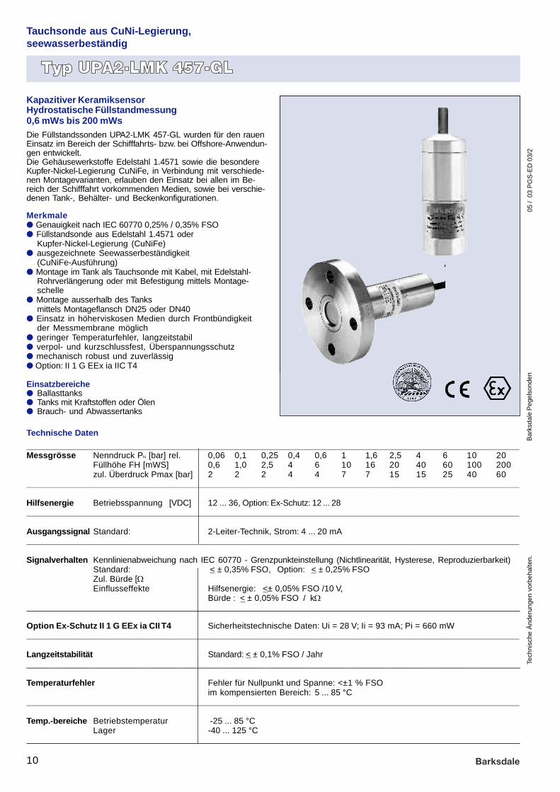
Tauchsonde aus CuNi-Legierung,seewasserbeständig
Die Füllstandssonden UPA2-LMK 457-GL wurden für den rauenEinsatz im Bereich der Schifffahrts- bzw. bei Offshore-Anwendun-gen entwickelt.Die Gehäusewerkstoffe Edelstahl 1.4571 sowie die besondereKupfer-Nickel-Legierung CuNiFe, in Verbindung mit verschiede-nen Montagevarianten, erlauben den Einsatz bei allen im Be-reich der Schifffahrt vorkommenden Medien, sowie bei verschie-denen Tank-, Behälter- und Beckenkonfigurationen.
Merkmalel Genauigkeit nach IEC 60770 0,25% / 0,35% FSOl Füllstandsonde aus Edelstahl 1.4571 oder
Kupfer-Nickel-Legierung (CuNiFe)l ausgezeichnete Seewasserbeständigkeit
(CuNiFe-Ausführung)l Montage im Tank als Tauchsonde mit Kabel, mit Edelstahl-
Rohrverlängerung oder mit Befestigung mittels Montage-schelle
l Montage ausserhalb des Tanksmittels Montageflansch DN25 oder DN40
l Einsatz in höherviskosen Medien durch Frontbündigkeitder Messmembrane möglich
l geringer Temperaturfehler, langzeitstabill verpol- und kurzschlussfest, Überspannungsschutzl mechanisch robust und zuverlässigl Option: II 1 G EEx ia IIC T4
Einsatzbereichel Ballasttanksl Tanks mit Kraftstoffen oder Ölenl Brauch- und Abwassertanks
Technische Daten
Kapazitiver KeramiksensorHydrostatische Füllstandmessung0,6 mWs bis 200 mWs
______________________________________________________________________________________________________Messgrösse Nenndruck PN [bar] rel. 0,06 0,1 0,25 0,4 0,6 1 1,6 2,5 4 6 10 20
Füllhöhe FH [mWS] 0,6 1,0 2,5 4 6 10 16 20 40 60 100 200zul. Überdruck Pmax [bar] 2 2 2 4 4 7 7 15 15 25 40 60
______________________________________________________________________________________________________
Hilfsenergie Betriebsspannung [VDC] 12 ... 36, Option: Ex-Schutz: 12 ... 28______________________________________________________________________________________________________
Ausgangssignal Standard: 2-Leiter-Technik, Strom: 4 ... 20 mA______________________________________________________________________________________________________
Signalverhalten Kennlinienabweichung nach IEC 60770 - Grenzpunkteinstellung (Nichtlinearität, Hysterese, Reproduzierbarkeit)Standard: < ± 0,35% FSO, Option: < ± 0,25% FSOZul. Bürde [W] Strom 2-Leiter: [ UB (V) - 12V] / 0,02 AEinflusseffekte Hilfsenergie: <± 0,05% FSO /10 V,
Bürde : < ± 0,05% FSO / kW
Option Ex-Schutz II 1 G EEx ia CII T4 Sicherheitstechnische Daten: Ui = 28 V; Ii = 93 mA; Pi = 660 mW______________________________________________________________________________________________________
Langzeitstabilität Standard: < ± 0,1% FSO / Jahr___________________________________________________________________________________________________
Temperaturfehler Fehler für Nullpunkt und Spanne: <±1 % FSOim kompensierten Bereich: 5 ... 85 °C
______________________________________________________________________________________________________
Temp.-bereiche Betriebstemperatur -25 ... 85 °CLager -40 ... 125 °C

05 /
03
PG
S-E
D 0
3/2
Spe
cific
atio
ns a
re s
ubje
ct
to c
hang
es w
ithou
t no
tice.
Bar
ksda
le L
evel
Pro
bes
11
Tauchsonde aus CuNi-Legierung,seewasserbeständig
______________________________________________________________________________________________________
Mechanische Festigkeit Vibration nach IEC 60 068-2-6______________________________________________________________________________________________________
Elektrischer Anschluss Spezial-Kabel mit eingearbeitetem Luftschlauch als Referenzbezug zumumgebenden Luftdruck
______________________________________________________________________________________________________
Kabelschutz Standard ohne KabelschutzSonderausführung Edelstahlrohr (lieferbar als Kompaktgerät mit Edelstahlrohrverlängerung
mit einer Länge bis zu 2 m)______________________________________________________________________________________________________
Materialien Gehäuse Edelstahl 1.4571Option seewasserbeständig: Kupfer-Nickel-Legierung (CuNi10Fe1Mn)Andere: auf Anfrage
Trennmembrane Keramik Al2O3 96 %Dichtungen Viton (FKM) / Andere: auf AnfrageKabelmantel PUR schwarz, seewasserbeständig, halogenfrei, temperaturbeständig
bis 125 °C, andere: auf Anfrage______________________________________________________________________________________________________
Sonstiges Schutzart IP68 (DIN 40 050)Gewicht ca. 400 g (ohne Kabel)
______________________________________________________________________________________________________
Montagezubehör Montageschelle aus Edelstahl(Nicht im Lieferumfang enthalten) Montageflansch für Tauchsondenbefestigung aus Stahl verzinkt DN25 / PN16___________________________________________________________________________________________________
Technische Daten
Bauart
Tauchsonde X X
Flanschsonde X
Optionen / Sonderausführungen
Einsatz im explosionsgefährdeten Bereich X X
Gehäusematerial
Edelstahl 1.4571 Kupfer-Nickel-LegierungCuNiFe
Typenübersicht
Tech
nisc
he Ä
nder
unge
n vo
rbeh
alte
n.B
arks
dale
Peg
elso
nden
05 /
03
PG
S-E
D 0
3/2
12
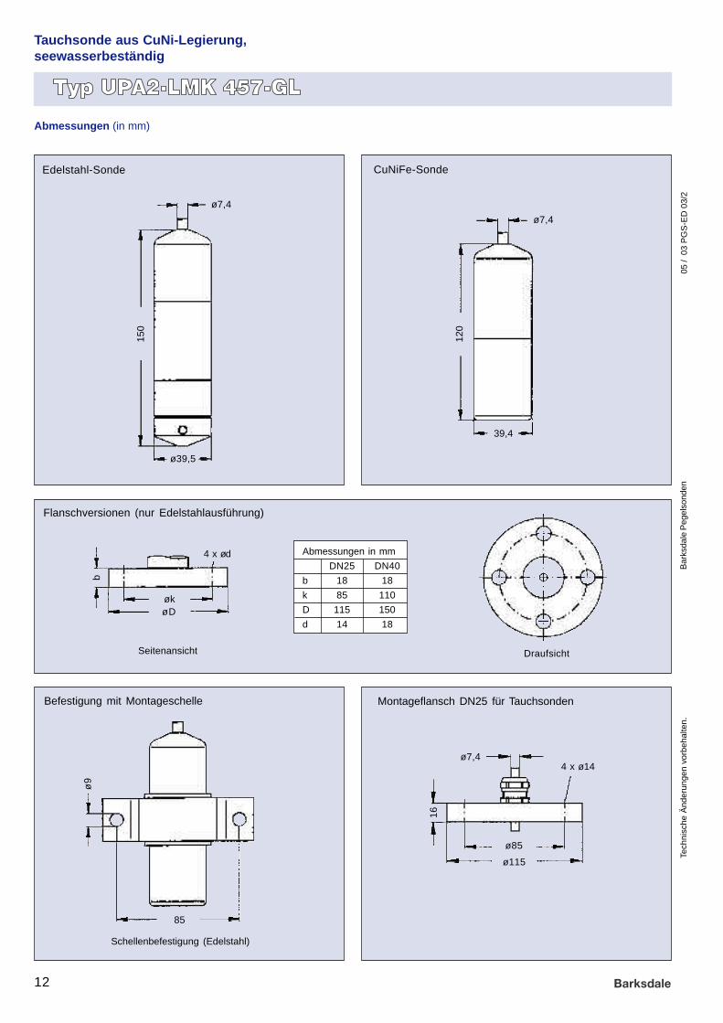
Abmessungen (in mm)
Edelstahl-Sonde
ø39,5
ø7,4
39,4
150
120
16
CuNiFe-Sonde
ø7,4
øk
ø7,4
b
Befestigung mit Montageschelle
Flanschversionen (nur Edelstahlausführung)
Montageflansch DN25 für Tauchsonden
DraufsichtSeitenansicht
4 x ød
øD
Abmessungen in mm
DN25 DN40
b 18 18
k 85 110
D 115 150
d 14 18
ø85
ø9
Schellenbefestigung (Edelstahl)
4 x ø14
85
ø115
Tauchsonde aus CuNi-Legierung,seewasserbeständig

Spe
cific
atio
ns a
re s
ubje
ct
to c
hang
es w
ithou
t no
tice.
Bar
ksda
le L
evel
Pro
bes
05 /
03
PG
S-E
D 0
3/2
13
Bestellnummernbeispiel
barmWs
(4)SpezialPUR-Kabel
(X)Andere
(3)0,35%Standard
(2)0,25%Option
Messbereich[bar] [mWS]
Mess-grösse
Kabellänge[m]
Genauigkeit
DichtungMess-bereich
Mess-grösse
Ausgangs-signal
ElektrischerAnschluss
BauartTyp Serie
bar 1000 1 3 1
Ihre Bestellnummer
Elektr.Anschluss
XXX
(z. B.:3 m = 003)
3 UPA2 LMK 457-GL
UPA2 LMK 457-GL
0,06 0,6 06000,1 1,0 10000,25 2,5 25000,4 4,0 40000,6 6,0 60001,0 10 10011,6 16 16012,5 25 25014,0 40 40016,0 60 600110 100 100216 160 160220 200 2002
Gehäuse-material
Bauart Dichtung
(1)Edelstahl1.4571
(K)Kupfer-Nickel-LegierungCuNiFe
(1)4... 20 mAZweileiter
(E)4... 20 mAZweileiterEx-SchutzII 1 GEExiaIIC T4
Ausgangs-signal
(1)Tauch-sonde
(3)Flansch-sondeDN25 /PN16 1)
(4)Flansch-sondeDN40 /PN16 1)
(1)Viton(FKM)
(3)EPDM
Genauig-keit
Gehäuse-material
4
Kabel-länge
0032
1) nicht in Verbindung mit Gehäuse aus Kupfer-Nickel-Legierung (CuNiFe)
Bestellnummer Bezeichnung
916-0366 Montageschelle aus Edelstahl
906-0812 Montageflansch für Tauchsondenbefestigung aus Stahl verzinkt DN25 / PN16
Zubehör
Versorgung +
Versorgung – 12...36 VDC
2-Leiter: 4...20 mA
AnschlussschaltbildAnschlusstabelle
Elektrische AnschlüsseAnschlußbelegung Kabelfarben nach DIN 47100
2-Leiter-System:Versorgung + weissVersorgung – braun
Masse Kabelschirm
Tauchsonde aus CuNi-Legierung,seewasserbeständig

05 /
03
PG
S-E
D 0
3/2
Tech
nisc
he Ä
nder
unge
n vo
rbeh
alte
n.B
arks
dale
Peg
elso
nden
14
Der Druckmessumformer Typ UPA2-DMP 457-GL ist konzipiertfür härteste Einsatzbedingungen, was Umweltbelastungen,Schock- und Vibrationsfestigkeit, sowie dynamische Belastbar-keit betrifft. Neben der hohen Messgenauigkeit zeichnet er sichbesonders durch seine ausgezeichnete Langzeitstabilität aus.
Merkmalel Edelstahlsensor aus 1.4571 bzw. 1.4401l Druckanschluss: Zoll- und NPT-Gewindel Druckbereiche zwischen 0 ... 100 mbar und 0 ... 600 barl Genauigkeit nach IEC 60770 0,25% / 0,35% FSOl Ausgangssignal 4 ... 20 mA / 2-Leiterl langzeitstabill hohe elektrische Betriebssicherheit
(verpol- und kurzschlussfest, Überspannungsschutz)l mechanisch robust und zuverlässig, hohe Lebensdauerl Option: II 1 G EEx ia IIC T4 (TÜV 99 ATEX 1504 X)
Einsatzbereiche im Bereich Schifffahrt / Offshore sind:l Dieselmotorenl Getriebel Verdichterl Pumpenl Kessell Aufzüge
Industrie-Druckmessumformerfür Schifffahrt- und Offshore-Anwendungen
Technische Daten
Niederdruckbereich [bar]Nenndruck PN rel -1...0 0...0,1 0...0,25 0...0,4 0...0,6 0...1,0 0...1,6 0...2,5 0...4 0...6 0...10 0...16 0...25Nenndruck PN abs – – – – 0...0,6 0...1,0 0...1,6 0...2,5 0...4 0...6 0...10 0...16 0...25zul. Überdruck Pmax 3 1 1 1 3 3 6 6 20 20 20 60 100
______________________________________________________________________________________________________Hochdruckbereich
Nenndruck PN 1) 0 ... 40 0 ... 60 0 ... 100 0 ... 160 0 ... 250 0 ... 400 0 ... 600zul. Überdruck Pmax 140 140 340 340 600 600 1000
______________________________________________________________________________________________________Hilfsenergie
Betriebsspannung 12 ... 36 V DC,Option Ex-Schutz:12... 28 V DC______________________________________________________________________________________________________Ausgangssignal Standard: 2-Leiter-Technik,Strom: 4...20 mA______________________________________________________________________________________________________Signalverhalten Kennlinienabweichung nach IEC 60770 - Grenzpunkteinstellung (Nichtlinearität, Hysterese, Reproduzierbarkeit)
Standard: < ± 0,35% FSO 2), Option: < ± 0,25% FSO
3)
Zul. Bürde [W] Strom 2-Leiter:[ UB (V) - 12V] / 0,02 AEinflusseffekte Hilfsenergie: < ± 0,05% FSO / 10 V Bürde: < ± 0,05% FSO / kWLangzeitstabilität < ± 0,2% FSO / Jahr
______________________________________________________________________________________________________Option Ex-Schutz (II 1 G EEx ia CII T4) Sicherheitstechnische Daten: Ui = 28 V; Ii = 93 mA; Pi = 660 mW______________________________________________________________________________________________________Temperaturfehler
Nenndruck PN [bar] -1...0 0...0,1 0...0,25 0...0,4 0...0,6 0...1,0 0...1,6 0...2,5 0...4 0...6 0...10 0...16 0...25Fehlerband [±% FSO] 4) im <0,75 <2,0 <1,5 <1,0 <0,75kompens. Bereich [°C] 0...70 0... 50 0...50 0...70 0...70Hochdruckbereich (PN>40 bar) < 1% FSO
______________________________________________________________________________________________________Temperaturbereiche [°C]
Medium -25 ... 125Elektronik/Umgebung -25 ... 85Lager -40 ... 125
______________________________________________________________________________________________________Schutzart
Standard IP65 GL-approbierter Stecker inkl. Kabeldose, Optionen IP67:Kabelverschraubung mit 2 m Kabel______________________________________________________________________________________________________Mechanische Anschlüsse
Standard G ½ DIN EN 837-1/-3 (DIN 16288),Optionen G ½ “ NPT, G ½ DIN 3852 frontbündig
1) Messanfang bei Umgebungsdruck, 3) Nenndruck PN >0,4 bar2) Nenndruck PN 0,1 ... 0,4 bar: <±0,50% FSO 4) Fehlerband für Nullpunkt und Spanne
Edelstahl-Druckmessumformerfür Füllstandmessungen
05 /
03
PG
S-E
D 0
3/2
Spe
cific
atio
ns a
re s
ubje
ct
to c
hang
es w
ithou
t no
tice.
Bar
ksda
le L
evel
Pro
bes
15
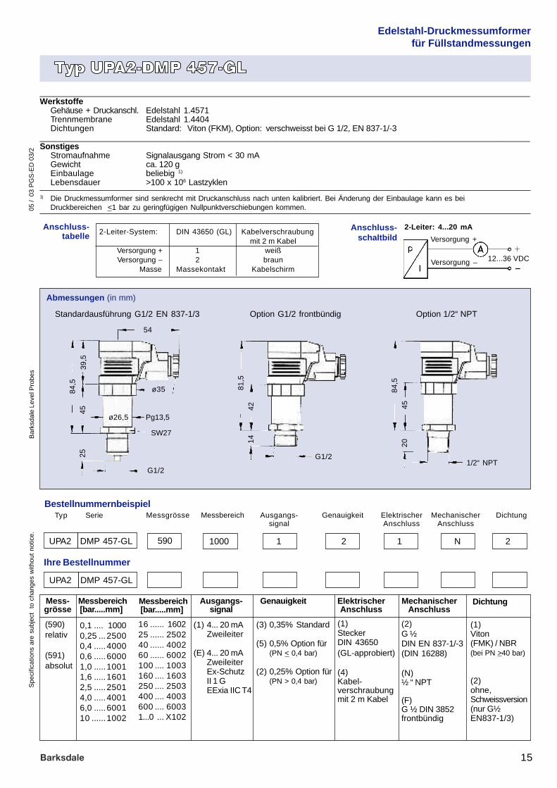
______________________________________________________________________________________________________Werkstoffe
Gehäuse + Druckanschl. Edelstahl 1.4571Trennmembrane Edelstahl 1.4404Dichtungen Standard: Viton (FKM), Option: verschweisst bei G 1/2, EN 837-1/-3
______________________________________________________________________________________________________Sonstiges
Stromaufnahme Signalausgang Strom < 30 mAGewicht ca. 120 gEinbaulage beliebig 1)
Lebensdauer >100 x 106 Lastzyklen
1) Die Druckmessumformer sind senkrecht mit Druckanschluss nach unten kalibriert. Bei Änderung der Einbaulage kann es beiDruckbereichen <1 bar zu geringfügigen Nullpunktverschiebungen kommen.
Bestellnummernbeispiel
(590)relativ
(591)absolut
Messbereich[bar.....mm]
Mess-grösse
Ausgangs-signal
MechanischerAnschluss
Genauigkeit
GenauigkeitMessbereichMessgrösse Ausgangs-signal
ElektrischerAnschluss
DichtungTyp Serie
590 1000 1 2 1
Ihre Bestellnummer
ElektrischerAnschluss
(2)G ½DIN EN 837-1/-3(DIN 16288)
(N)½ “ NPT
(F)G ½ DIN 3852frontbündig
N UPA2 DMP 457-GL
(1)SteckerDIN 43650(GL-approbiert)
(4)Kabel-verschraubungmit 2 m Kabel
Dichtung
(1)Viton(FMK) / NBR(bei PN >40 bar)
(2)ohne,Schweissversion(nur G½EN837-1/3)
MechanischerAnschluss
2
16 ...... 160225 ...... 250240 ...... 400260 ...... 6002100 .... 1003160 .... 1603250 .... 2503400 .... 4003600 .... 60031...0 ... X102
(1) 4... 20 mAZweileiter
(E) 4... 20 mAZweileiterEx-SchutzII 1 GEExia IIC T4
0,1 .... 10000,25 ... 25000,4 .....40000,6 .....60001,0 .....10011,6 .....16012,5 .....25014,0 .....40016,0 .....600110 ......1002
Abmessungen (in mm)
Standardausführung G1/2 EN 837-1/3
UPA2 DMP 457-GL
Messbereich[bar.....mm]
(3) 0,35% Standard
(5) 0,5% Option für(PN < 0,4 bar)
(2) 0,25% Option für(PN > 0,4 bar)
ø35
G1/2
Pg13,5ø26,5
54
SW27
84,5
2539
,545
G1/2
81,5
1442
1/2“ NPT
84,5
2045
Option 1/2“ NPTOption G1/2 frontbündig
Anschluss-schaltbild
Anschluss-tabelle 2-Leiter-System: DIN 43650 (GL) Kabelverschraubung
mit 2 m KabelVersorgung + 1 weißVersorgung – 2 braun
Masse Massekontakt Kabelschirm
Versorgung +
Versorgung – 12...36 VDC
2-Leiter: 4...20 mA
Edelstahl-Druckmessumformerfür Füllstandmessungen
05 /
03
PG
S-E
D 0
3/2
Tech
nisc
he Ä
nder
unge
n vo
rbeh
alte
n.B
arks
dale
Peg
elso
nden
16
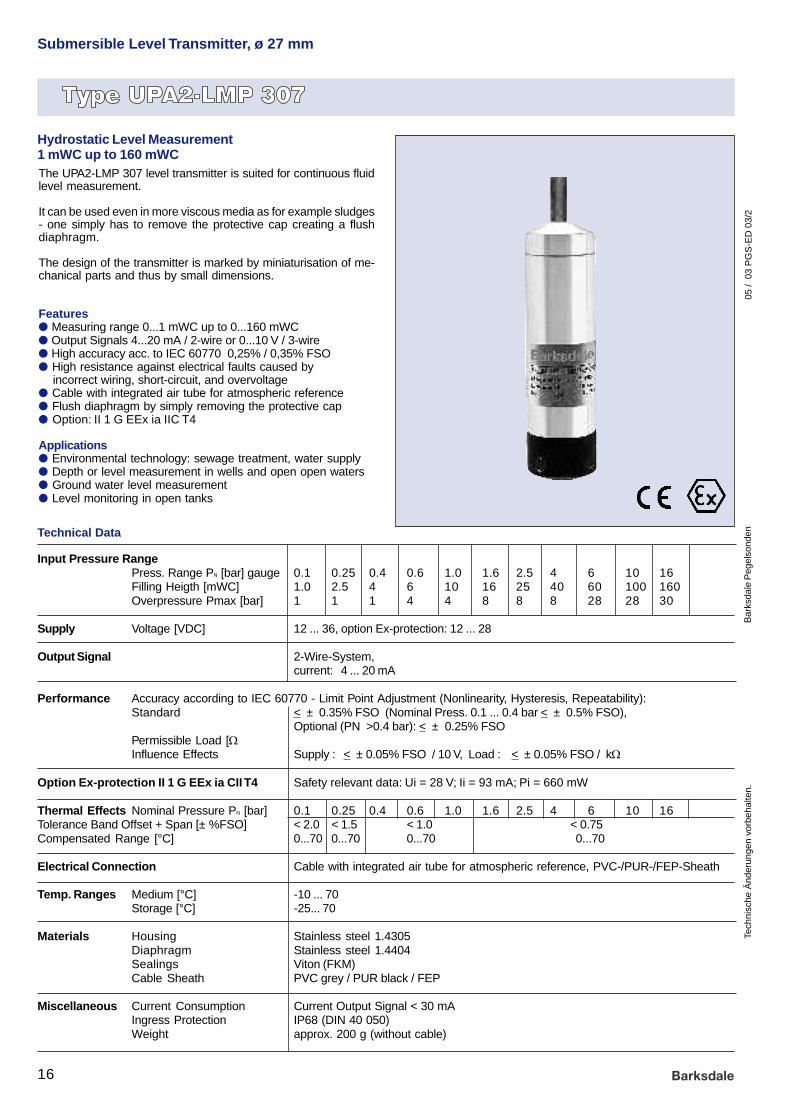
Input Pressure RangePress. Range PN [bar] gauge 0.1 0.25 0.4 0.6 1.0 1.6 2.5 4 6 10 16Filling Heigth [mWC] 1.0 2.5 4 6 10 16 25 40 60 100 160Overpressure Pmax [bar] 1 1 1 4 4 8 8 8 28 28 30
Supply Voltage [VDC] 12 ... 36, option Ex-protection: 12 ... 28
Output Signal 2-Wire-System,current: 4 ... 20 mA
Performance Accuracy according to IEC 60770 - Limit Point Adjustment (Nonlinearity, Hysteresis, Repeatability):Standard < ± 0.35% FSO (Nominal Press. 0.1 ... 0.4 bar < ± 0.5% FSO),
Optional (PN >0.4 bar): < ± 0.25% FSOPermissible Load [W] Current 2-Wire: [ UB (V) - 12V] / 0.02 AInfluence Effects Supply : < ± 0.05% FSO / 10 V, Load : < ± 0.05% FSO / kW
Option Ex-protection II 1 G EEx ia CII T4 Safety relevant data: Ui = 28 V; Ii = 93 mA; Pi = 660 mW
Thermal Effects Nominal Pressure PN [bar] 0.1 0.25 0.4 0.6 1.0 1.6 2.5 4 6 10 16Tolerance Band Offset + Span [± %FSO] < 2.0 < 1.5 < 1.0 < 0.75Compensated Range [°C] 0...70 0...70 0...70 0...70
Electrical Connection Cable with integrated air tube for atmospheric reference, PVC-/PUR-/FEP-Sheath
Temp. Ranges Medium [°C] -10 ... 70Storage [°C] -25... 70
Materials Housing Stainless steel 1.4305Diaphragm Stainless steel 1.4404Sealings Viton (FKM)Cable Sheath PVC grey / PUR black / FEP
Miscellaneous Current Consumption Current Output Signal < 30 mAIngress Protection IP68 (DIN 40 050)Weight approx. 200 g (without cable)
Submersible Level Transmitter, ø 27 mm
Technical Data
Hydrostatic Level Measurement1 mWC up to 160 mWCThe UPA2-LMP 307 level transmitter is suited for continuous fluidlevel measurement.
It can be used even in more viscous media as for example sludges- one simply has to remove the protective cap creating a flushdiaphragm.
The design of the transmitter is marked by miniaturisation of me-chanical parts and thus by small dimensions.
Featuresl Measuring range 0...1 mWC up to 0...160 mWCl Output Signals 4...20 mA / 2-wire or 0...10 V / 3-wirel High accuracy acc. to IEC 60770 0,25% / 0,35% FSOl High resistance against electrical faults caused by incorrect wiring, short-circuit, and overvoltagel Cable with integrated air tube for atmospheric referencel Flush diaphragm by simply removing the protective capl Option: II 1 G EEx ia IIC T4
Applicationsl Environmental technology: sewage treatment, water supplyl Depth or level measurement in wells and open open watersl Ground water level measurementl Level monitoring in open tanks

05 /
03
PG
S-E
D 0
3/2
Spe
cific
atio
ns a
re s
ubje
ct
to c
hang
es w
ithou
t no
tice.
Bar
ksda
le L
evel
Pro
bes
17
Order number example
(1) 4... 20 mA2-wire
(E) 4... 20 mA2-wireEx-protectionII 1 GEExia IIC T4
barmWC
(1) PVC-cable
(2) PUR-cable
(3) FEP-cable
0,1 1,0 10000,25 2,5 25000,4 4,0 40000,6 6,0 60001,0 10 10011,6 16 16012,5 25 25014,0 40 40016,0 60 600110 100 100216 160 1602
(3) 0,35% Standard
(5) Option 0,5%(at PN < 0,4 bar)
(2) Option 0,25%(at PN > 0,4 bar)
Measuring range[bar] [mWC]
Unit Outputsignal
Cable length[m]
Accuracy
Measuringrange
Unit Outputsignal
Electricalconnection
AccuracyType Series
bar 1000 1 5 1
Your order number
Electricalconnection
XXX
(e. g.: 5 m = 005)
Cablelength
005
UPA2 LMP 307
UPA2 LMP 307
Submersible Level Transmitter, ø 27 mm
Protection cap removable = flush diaphragm
Dimensions (in mm)
122
ø 27 ø 27
ø 7,4 ø 7,4
Connection chart
Electrical connecetionsWiring Cable colours acc. to DIN 47100
2-wire system: Supply + white Supply – brown Earth Cable shield
Supply +
Supply – 12...36 VDC
2-wire: 4...20 mA
Electrical connection
Option: Ex-protection

05 /
03
PG
S-E
D 0
3/2
Tech
nisc
he Ä
nder
unge
n vo
rbeh
alte
n.B
arks
dale
Peg
elso
nden
18
Submersible Level Transmitter, ø 40 mm
Technical Data
Capacitive Ceramic SensorHydrostatic Level Measurement0,6 mWC up to 200 mWC
The submersible transmitter UPA2-LMK 358 has been de-signed for continuous level measurement for very small fillingheights. This special ability is achieved by using a very sensi-tive ceramic pressure sensor.Usage in high viscous media such as slurries is possible be-cause of the flush diaphragm.
Featuresl ceramic pressure sensor, excellent linearityl high resistance against electrical faults caused by in
correct wiring, short-circuit and overvoltagel cable with integrated air tube for atmospheric referencel transmitter and cable assembly pluggedl usage with higher viscous media possible because of
flush diapraghml cable protection with stainless steel pipe availablel different mounting alternativesl Option: II 1 G EEx ia IIC T4
Applicationsl level measurement in open tanks with small filling heightsl depth or level measurement in wells and open watersl ground water level measurementl water supply and sewage treatmentl chemical and medcial industry
Input Pressure RangePress. Range PN [bar] gauge 0,06 0,1 0,25 0,4 0,6 1 1,6 2,5 4 6 10 20Filling Height FH [mWC] 0,6 1,0 2,5 4 6 10 16 20 40 60 100 200Overpressure Pmax [bar] 2 2 2 4 4 7 7 15 25 25 40 60
Supply Voltage [VDC] 12 ... 36
Output Signal Standard 2-wire-system, current: 4 ... 20 mA
Performance Accuracy according to IEC 60770 - Limit Point Adjustment (Nonlinearity, Hysteresis, Repeatability)Standard < ± 0,35% FSOPermissible Load [W] Current 2-wire system: [ UB (V) - 12V] / 0,02 AInfluence Effects Supply < ± 0,05% FSO / 10 V, Load : < ± 0,05% FSO / kW
Option Ex-protection II 1 G EEx ia CII T4 Safety relevant data: Ui = 28 V; Ii = 93 mA; Pi = 660 mW
Thermal Effects Tolerance Band Offset and Span in compensated Range:10 ... 70°C: < ± 0,1 % FSO / 10 K
Electrical Connection Cable with integrated air tube for atmospheric reference PVC-/PUR-/FEP SheathSpecial: Mounting in SS (prepared)
Temp. Ranges Medium [°C] -10 ... 70Storage [°C] -25 ... 70
Materials Housing 1.4571Diaphragm Ceramics Al2O3 96 % / Others: on requestSeals Viton (FKM) / Option: EPDMCable Sheath PVC gray / PUR black / FEP
Miscellaneous Current Consumption < 30 mAIngress Protection IP68 (DIN 40 050)Weight approx. 400 g (without cable)
Accessories Mounting flange made of PVC grey DN10/PN10Mounting clamp Stainless Steel

05 /
03
PG
S-E
D 0
3/2
Spe
cific
atio
ns a
re s
ubje
ct
to c
hang
es w
ithou
t no
tice.
Bar
ksda
le L
evel
Pro
bes
19
Order number example
(1) 4... 20 mA2-wire
(E) 4... 20 mA2-wireEx-protectionII 1 GEExia IIC T4
barmWC
(1) PVC-cable
(2) PUR-cable
(3) FEP-cable
(1) Viton
(3) EPDM
OptionsMeasuring range[bar] [mWC]
Unit Outputsignal
Cable length[m]
Sealing
OptionsMeasuringrange
Unit Outputsignal
Electricalconnection
SealingType Series
bar 1000 1 1 1
Your order number
Electricalconnection
(6) Mounting instainlesssteel tube(prepared)
XXX
(e. g.:5 m = 005)
Cablelength
005
UPA2 LMK 358
UPA2 LMK 358
0,06 0,6 06000,1 1,0 10000,25 2,5 25000,4 4,0 40000,6 6,0 60001,0 10 10011,6 16 16012,5 25 25014,0 40 40016,0 60 600110 100 100216 160 160220 200 2002
Submersible Level Transmitter, ø 40 mm
Standard Special version cable shield Other features
Without cable shield Stainless Steel tube Transmitter and cable plugged
Dimensions (in mm)19
2
ø 40
ø35
ø 7,4
Supply +
Supply – 12...36 VDC
2-wire: 4...20 mA
Electrical connection
Connection chart
Electrical connecetionsWiring Cable colours acc. to DIN 47100
2-wire system: Supply + white Supply – brown Earth Cable shield
05 /
03
PG
S-E
D 0
3/2
Tech
nisc
he Ä
nder
unge
n vo
rbeh
alte
n.B
arks
dale
Peg
elso
nden
20
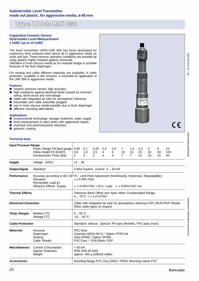
Submersible Level Transmittermade out plastic, for aggressive media, ø 40 mm
Technical Data
Capacitive Ceramic SensorHydrostatic Level Measurement1 mWC up to 10 mWC
The level transmitter UPA2-LMK 858 has been developed forcontinuous level measure-ment above all in aggressive media asacids and lyes. These extreme operation conditions are possible byusing plastics highly resistant against chemicals.Utilization in more viscous media as for example sludge is possiblebecause of the flush diaphragm.
For sealing and cable different materials are available. A cableprotection, available in two versions, is essential for application ofthe LMK 858 in aggressive media.
Featuresl ceramic pressure sensor, high accuracyl high resistance against electrical faults caused by incorrect
wiring, short-circuit and overvoltagel cable with integrated air tube for atmospheric referencel transmitter and cable assembly pluggedl use in more viscous media possible due to flush diaphragml different mounting alternatives
Applicationsl environmental technology: sewage treatment, water supplyl level measurement in open tanks with aggressive liquidsl chemical and pharmaceutical industriesl galvanic coating
Input Pressure RangePress. Range PN [bar] gauge 0,06 0,1 0,25 0,4 0,6 1 1,6 2,5 4 6 10Filling Height FH [mWC] 0,6 1,0 2,5 4 6 10 16 20 40 60 100Overpressure Pmax [bar] 2 2 2 4 4 7 7 15 25 25 40
Supply Voltage [VDC] 12 ... 36
Output Signal Standard: 2-Wire System, current: 4 ... 20 mA
Performance Accuracy according to IEC 60770 - Limit Point Adjustment (Nonlinearity, Hysteresis, Repeatability):Standard < ± 0.35% FSOPermissible Load [W] Current 2-Wire: [ UB (V) - 12V] / 0.02 AInfluence Effects Supply : < ± 0.05% FSO / 10 V, Load: < ± 0.05% FSO / kW
Thermal Effects Tolerance Band Offset and Span within Compensated Range:0 ... 70°C: < ± 1.0 % FSO
Electrical Connection Cable with integrated air tube for atmospheric reference PVC-/PUR-/FEP-SheathOther cable types on request
Temp. Ranges Medium [°C] 0 ... 50 °CStorage [°C] -10 ... 50 °C
Cable Protection Standard: without; Special: PP-pipe (flexible), PVC-pipe (hard)
Materials Housing PVC GreyDiaphragm Ceramics Al2O3 96 % / Option: PTFE foilSealing Viton (FKM) / Option: EPDMCable Sheath PVC Grey / PUR Black / FEP
Miscellaneous Current Consumption < 30 mAIngress Protection IP68 (DIN 40 050)Weight approx. 400 g (without cable)
Accessories Mounting flange PVC Grey DN10 / PN10; Mounting clamp PVC

05 /
03
PG
S-E
D 0
3/2
Spe
cific
atio
ns a
re s
ubje
ct
to c
hang
es w
ithou
t no
tice.
Bar
ksda
le L
evel
Pro
bes
21
Order number example
barmWC
(1) PVC-cable
(2) PUR-cable(with air tube)
(3) FEP-cable
OptionsMeasuring range[bar] [mWC]
Unit Outputsignal
Cable length[m]
Sealing
OptionsMeasuringrange
Unit Outputsignal
Electricalconnection
SealingType Series
bar 1000 1 1 1
Your order number
Electricalconnection
XXX
(e. g.:5 m = 005)
Cablelength
005
UPA2 LMK 858
UPA2 LMK 858
(2) Cable shieldPP-Wellrohr
(6) Cable shieldPVC-Wellrohr
Submersible Level Transmittermade out plastic, for aggressive media, ø 40 mm
(1) 4... 20 mA2-wire
(1) Viton
(3) EPDM
0,06 0,6 06000,1 1,0 10000,25 2,5 25000,4 4,0 40000,6 6,0 60001,0 10 10011,6 16 16012,5 25 25014,0 40 40016,0 60 600110 100 1002
Standard Special version cable shield Other features
Without cable shield Stainless Steel tube PP-Wellrohr Transmitter and cable plugged
Dimensions (in mm)21
1
ø 40
ø 35
ø 7,4
Pg16 Pg16
Supply +
Supply – 12...36 VDC
2-wire: 4...20 mA
Electrical connection
Connection chart
Electrical connecetionsWiring Cable colours acc. to DIN 47100
2-wire system: Supply + white Supply – brown Earth Cable shield
05 /
03
PG
S-E
D 0
3/2
Tech
nisc
he Ä
nder
unge
n vo
rbeh
alte
n.B
arks
dale
Peg
elso
nden
22
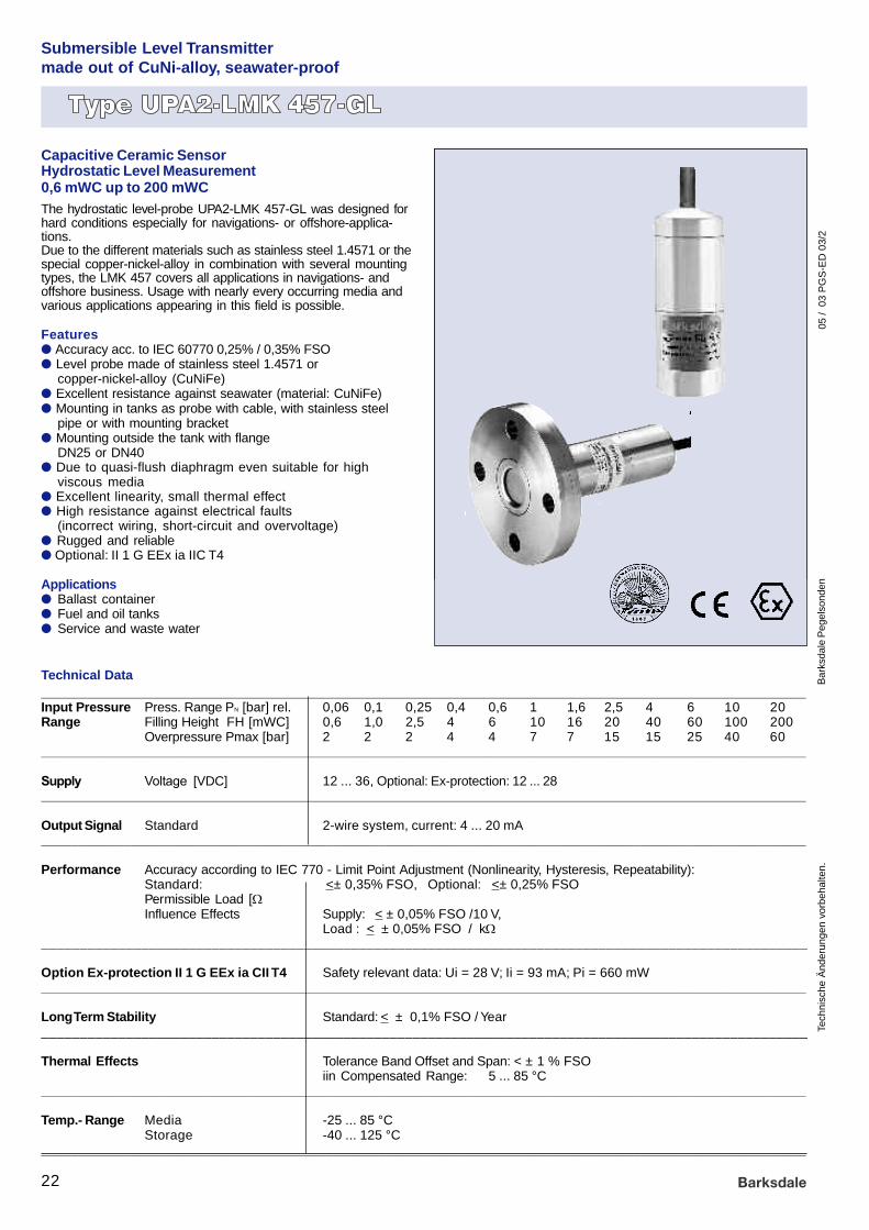
Submersible Level Transmittermade out of CuNi-alloy, seawater-proof
Technical Data
Capacitive Ceramic SensorHydrostatic Level Measurement0,6 mWC up to 200 mWCThe hydrostatic level-probe UPA2-LMK 457-GL was designed forhard conditions especially for navigations- or offshore-applica-tions.Due to the different materials such as stainless steel 1.4571 or thespecial copper-nickel-alloy in combination with several mountingtypes, the LMK 457 covers all applications in navigations- andoffshore business. Usage with nearly every occurring media andvarious applications appearing in this field is possible.
Featuresl Accuracy acc. to IEC 60770 0,25% / 0,35% FSOl Level probe made of stainless steel 1.4571 or
copper-nickel-alloy (CuNiFe)l Excellent resistance against seawater (material: CuNiFe)l Mounting in tanks as probe with cable, with stainless steel
pipe or with mounting bracketl Mounting outside the tank with flange
DN25 or DN40l Due to quasi-flush diaphragm even suitable for high
viscous medial Excellent linearity, small thermal effectl High resistance against electrical faults
(incorrect wiring, short-circuit and overvoltage)l Rugged and reliablel Optional: II 1 G EEx ia IIC T4
Applicationsl Ballast containerl Fuel and oil tanksl Service and waste water
______________________________________________________________________________________________________Input Pressure Press. Range PN [bar] rel. 0,06 0,1 0,25 0,4 0,6 1 1,6 2,5 4 6 10 20Range Filling Height FH [mWC] 0,6 1,0 2,5 4 6 10 16 20 40 60 100 200
Overpressure Pmax [bar] 2 2 2 4 4 7 7 15 15 25 40 60______________________________________________________________________________________________________
Supply Voltage [VDC] 12 ... 36, Optional: Ex-protection: 12 ... 28______________________________________________________________________________________________________
Output Signal Standard 2-wire system, current: 4 ... 20 mA______________________________________________________________________________________________________
Performance Accuracy according to IEC 770 - Limit Point Adjustment (Nonlinearity, Hysteresis, Repeatability):Standard: <± 0,35% FSO, Optional: <± 0,25% FSOPermissible Load [W] Current 2-wire: [ UB (V) - 12V] / 0,02 AInfluence Effects Supply: < ± 0,05% FSO /10 V,
Load : < ± 0,05% FSO / kW___________________________________________________________________________________________________
Option Ex-protection II 1 G EEx ia CII T4 Safety relevant data: Ui = 28 V; Ii = 93 mA; Pi = 660 mW______________________________________________________________________________________________________
Long Term Stability Standard: < ± 0,1% FSO / Year___________________________________________________________________________________________________
Thermal Effects Tolerance Band Offset and Span: < ± 1 % FSOiin Compensated Range: 5 ... 85 °C
______________________________________________________________________________________________________
Temp.- Range Media -25 ... 85 °CStorage -40 ... 125 °C
______________________________________________________________________________________________________

05 /
03
PG
S-E
D 0
3/2
Spe
cific
atio
ns a
re s
ubje
ct
to c
hang
es w
ithou
t no
tice.
Bar
ksda
le L
evel
Pro
bes
23
Submersible Transmittermade out of CuNi-alloy, seawater-proof
______________________________________________________________________________________________________
Mechanical Stability Vibration acc. to IEC 60 068-2-6______________________________________________________________________________________________________
Electrical Connection Special cable with integrated air tube for atmospheric reference______________________________________________________________________________________________________
Cable Protection Standard without cable protectionOptional Stainless steel pipe (available as compact product with stainless steel pipe
with a total length up to 2m)______________________________________________________________________________________________________
Materials Housing Stainless steel 1.4571Option seawater resistant: Copper-Nickel-Alloy (CuNi10Fe1Mn)Others: On Request
Diaphragm Ceramics Al2O3 96 %Seals Viton (FKM) / Others: On RequestCable Sheath PUR black, seawater resistant, halogen free, temperature resistant up to +125°C,
Others: On Request______________________________________________________________________________________________________
Miscellaneous Ingress Protection IP68 (DIN 40 050)Weight appr. 400 g (without cable)
______________________________________________________________________________________________________
Mounting Accessories Mounting clamp made of stainless steel(Not part of the supply) Mounting flange for fixing submerge transmitter made of stainless steel
galvanized DN25 / PN16___________________________________________________________________________________________________
Technische Daten
Type Overview
Type of construction
Submerge transmitter X X
Flange transmitter X
Options / Special versions
Intrinsic safety X X
Housing Material
Stainless steel 1.4571 Copper-Nickel-AlloyCuNiFe

Tech
nisc
he Ä
nder
unge
n vo
rbeh
alte
n.B
arks
dale
Peg
elso
nden
05 /
03
PG
S-E
D 0
3/2
24
Submersible Level Transmittermade out of CuNi-alloy, seawater-proof
Dimensions (in mm)
Stainless steel transmitter
ø39,5
ø7,4
39,4
150
120
16
CuNiFe transmitter
ø7,4
øk
ø7,4
b
Installation witn mounting clamp
Flange types (only stainless steel version)
Mounting flange DN25 for submerge transmitter
Top viewSide view
4 x ød
øD
Dimensions in mm
DN25 DN40
b 18 18
k 85 110
D 115 150
d 14 18
ø85
ø9
Clamp installation (Stainless steel)
4 x ø14
85
ø115

Spe
cific
atio
ns a
re s
ubje
ct
to c
hang
es w
ithou
t no
tice.
Bar
ksda
le L
evel
Pro
bes
05 /
03
PG
S-E
D 0
3/2
25
barmWs
(4)SpecialPUR-cable
(X)Others
(3)0,35%Standard
(2)0,25%Option
Accuracy
Type ofconstruction
Type Series
bar 1000 1 3 1
XXX
(e. g.:3 m = 003)
3 UPA2 LMK 457-GL
UPA2 LMK 457-GL
0,06 0,6 06000,1 1,0 10000,25 2,5 25000,4 4,0 40000,6 6,0 60001,0 10 10011,6 16 16012,5 25 25014,0 40 40016,0 60 600110 100 100216 160 160220 200 2002
Housingmaterial
Type ofconstruct.
(1)Stainlesssteel1.4571
(K)Copper-Nickel-alloyCuNiFe
(1)4... 20 mA2-wire
(E)4... 20 mA2-wireEx-protect.II 1 GEExiaIIC T4
(1)Submergetransmitter
(3)FlangetransmitterDN25 /PN16 1)
(4)FlangetransmitterDN40 /PN16 1)
(1)Viton(FKM)
(3)EPDM
AccuracyHousingmaterial
4 0032
1) not in combination with material copper-nickel-alloy (CuNiFe)
Order number Description
916-0366 Mounting clamp made of stainless steel
906-0812 Mounting flange for fixing submerge transmitter made of stainless steel galvanized DN25 / PN16
Accessories
Submersible Transmittermade out of CuNi-alloy, seawater-proof
Order number example
Your order number
Measuring range[bar] [mWC]
Unit Outputsignal
Cable length[m]
Sealing
Measuringrange
Unit Outputsignal
Electricalconnection
Sealing
Electricalconnection
Cablelength
Supply +
Supply – 12...36 VDC
2-wire: 4...20 mA
Electrical connectionConnection chart
Electrical connecetionsWiring Cable colours acc. to DIN 47100
2-wire system: Supply + white Supply – brown Earth Cable shield

05 /
03
PG
S-E
D 0
3/2
Tech
nisc
he Ä
nder
unge
n vo
rbeh
alte
n.B
arks
dale
Peg
elso
nden
26
The pressure transmitter UPA2-DMP 457-GL was designedfor use in applications with high requirements respectivelyenvironmental resilience, mechanical shock and vibrations ordynamic stress. Among the high accuracy the pressure trans-mitter distinguish on the excellent long term stability.
Featuresl Stainless steel sensor (1.4571 resp. 1.4401)l Pressure port: inch- and NPT-threadl Pressure ranges 0 ... 100 mbar up to 0 ... 600 barl Accuracy acc. to IEC 60770 0,25% / 0,35% FSOl Output signal 4 ... 20 mA / 2-wirel excellent long term stabilityl high resistance against electrical faults (caused by
incorrect wiring, short- circuit and overvoltage)l rugged and reliable, long operating lifel Optional: II 1 G EEx ia IIC T4 (TÜV 99 ATEX 1504 X)
Applications in navigation / offshore:l Diesel enginesl Gearsl Compressorsl Pumpsl Boilersl Elevators
Industrial Pressure Transmitterfor Navigation- and Offshore-Applications
Technical Data
Low Pressure Range [bar]Nominal Press. PN rel -1...0 0...0,1 0...0,25 0...0,4 0...0,6 0...1,0 0...1,6 0...2,5 0...4 0...6 0...10 0...16 0...25Nominal Press. PN abs – – – – 0...0,6 0...1,0 0...1,6 0...2,5 0...4 0...6 0...10 0...16 0...25Overpressure Pmax 3 1 1 1 3 3 6 6 20 20 20 60 100
______________________________________________________________________________________________________High Pressure Range
Nominal Press. PN 1) 0 ... 40 0 ... 60 0 ... 100 0 ... 160 0 ... 250 0 ... 400 0 ... 600Overpressure Pmax 140 140 340 340 600 600 1000
______________________________________________________________________________________________________Supply
Voltage 12 ... 36 V DC,Optional Ex-protection:12 ... 28 V DC______________________________________________________________________________________________________Output Signal Standard: 2-wire, current: 4 ... 20 mA______________________________________________________________________________________________________Performance Accuracy according to IEC 60770 - Limit Point Adjustment (Nonlinearity, Hysteresis, Repeatability):
Standard: < ± 0,35% FSO 2), Optional: < ± 0,25% FSO
3)
Permissible Load [W] Current 2-wire:[ UB (V) - 12V] / 0,02 AInfluence effects Supply: < ± 0,05% FSO / 10 V Load: < ± 0,05% FSO / kWLong Term Stability < ± 0,2% FSO / Year
______________________________________________________________________________________________________Option Ex-protection (II 1 G EEx ia CII T4) Safety relevant data: Ui = 28 V; Ii = 93 mA; Pi = 660 mW______________________________________________________________________________________________________Thermal Effects
Nominal Press. PN [bar] -1...0 0...0,1 0...0,25 0...0,4 0...0,6 0...1,0 0...1,6 0...2,5 0...4 0...6 0...10 0...16 0...25Tol. band [±% FSO] 4) im <0,75 <2,0 <1,5 <1,0 <0,75Compens. Range [°C] 0...70 0...50 0...50 0...70 0...70High Pressure Range (PN>40 bar) < 1% FSO
______________________________________________________________________________________________________Temperature Ranges [°C]
Medium -25 ... 125Electronic/Environment -25 ... 85Storage -40 ... 125
______________________________________________________________________________________________________Ingress Protection
Standard IP65 GL-qualified male and female plug DIN 43650, Optional IP67: Cable gland with 2 m cable______________________________________________________________________________________________________Mechanical Connection
Standard G ½ DIN EN 837-1/-3 (DIN 16288),Optional G ½ “ NPT, G ½ DIN 3852 flush diaphragm1) measurement starts with ambient pressure, 3) Nominal pressure PN >0,4 bar2) Nominal pressure PN 0,1 ... 0,4 bar: <±0,50% FSO 4) Tolerance band for offset and span
Stainless Steel Pressure Transmitterfor Level Measuring

05 /
03
PG
S-E
D 0
3/2
Spe
cific
atio
ns a
re s
ubje
ct
to c
hang
es w
ithou
t no
tice.
Bar
ksda
le L
evel
Pro
bes
27
Meas. range[bar.....mm]
Meas. range[bar.....mm]
(3) 0,35% Standard
(5) Option 0,5%(at PN < 0,4 bar)
(2) Option 0,25%(at PN > 0,4 bar)
______________________________________________________________________________________________________Materials
Housing + Press. Port Stainless steel 1.4571Diaphragm Stainless steel 1.4404Seals Standard: Viton (FKM), Optional: welded version (G 1/2, EN 837-1/-3)
______________________________________________________________________________________________________Miscellaneous
Current Consumption Signal output current <30 mAWeight appr. 120 gMounting Position any 1)
Operational Life >100 x 106 cycles
1) Transmitters are calibrated in vertical position, thread port showing down. Changing installation position may cause aslight offset shift with pressure ranges <1 bar.
(590)relative
(591)absolute
Unit Mechanicalconnection
UnitType Series
590 1000 1 2 1
(2)G ½DIN EN 837-1/-3(DIN 16288)
(N)½ “ NPT
(F)G ½ DIN 3852flush diaphragm
N
(1)PlugDIN 43650(GL-qualified)
(4)Cable glandwith 2 m cable
(1)Viton(FMK) / NBR(at PN >40 bar)
(2)without,welded version(only G½EN837-1/3)
2
16 ...... 160225 ...... 250240 ...... 400260 ...... 6002100 .... 1003160 .... 1603250 .... 2503400 .... 4003600 .... 60031...0 ... X102
(1) 4... 20 mA2-wire
(E) 4... 20 mA2-wireEx-protectionII 1 GEExia IIC T4
0,1 .... 10000,25 ...25000,4 .....40000,6 .....60001,0 .....10011,6 .....16012,5 .....25014,0 .....40016,0 .....600110 ......1002
2-wire system: DIN 43650 (GL) Cable gland with2 m cable
Supply + 1 whiteSupply – 2 brown
Ground Ground pin Cable shield
Supply +
Supply – 12...36 VDC
2-wire: 4...20 mA
Stainless Steel Pressure Transmitterfor Level Measuring
Order number example
Your order number
Accuracy
Accuracy
Outputsignal
Sealing
Measuringrange
Outputsignal
Electricalconnection
Sealing
Electricalconnection
Mechanicalconnection
UPA2 DMP 457-GL
UPA2 DMP 457-GL
Dimensions (in mm)
Standard G1/2 EN 837-1/3
ø35
G1/2
Pg13,5ø26,5
54
nut acrossflats 27
84,5
2539
,545
G1/2
81,5
1442
1/2“ NPT
84,5
2045
Option 1/2“ NPTOption G1/2 flush diaphragm
Connectionchart
Electricalconnection
Tech
nisc
he Ä
nder
unge
n vo
rbeh
alte
n.B
arks
dale
Peg
elso
nden
05 /
03
PG
S-E
D 0
3/2
28
Mechanische Druckschalter
Elektronische Drucksensoren
Elektronische Druckschalter
Schwimmerschalter
Kontinuierliche Tankfüllstandmessung
Pegelsonden
Bypass-Niveauanzeiger
Strömungswächter
Mechanische Temperaturschalter
Elektronische Temperatursensoren
Elektronische Temperaturschalter
Scherschluss- / Luftfeder-Ventile
Der schnellste Weg zu mehr Informationen:Für jede unserer Produktgruppen gibt es einen ausführlichen Katalog.Um Ihnen schnellstmöglich Fragen zu technischen Details zu einem oder mehrerer unserer Produktebeantworten zu können, haben wir den untenstehenden Fax-Vordruck für Sie vorbereitet.Einfach kopieren, ausfüllen und absenden - Sie erhalten umgehend die gewünschten Unterlagen!
Fax an : Barksdale GmbHDorn-Assenheimer Strasse 27D-61203 Reichelsheim
Fax: +49 (0) 60 35 - 9 49-111
Absender: Vor- und Zuname : .............................................................................................................
Firma : .............................................................................................................
Abteilung : .............................................................................................................
Strasse / Postf. : .............................................................................................................
PLZ / Ort : .............................................................................................................
Tel.-Durchwahl : .............................................................................................................
Fax : .............................................................................................................
e-mail : .............................................................................................................
Datum : ............................................................
Bitte senden Sie mir ausführliche Informationen über:
Bitte senden Sie mir die Barksdale Produkt-CD mit allen verfügbaren Informationenüber die gesamte Produktpalette (PDF-Format).

Spe
cific
atio
ns a
re s
ubje
ct
to c
hang
es w
ithou
t no
tice.
Bar
ksda
le L
evel
Pro
bes
05 /
03
PG
S-E
D 0
3/2
29
The fastest way to more information:
. . . just complete the order form below and fax it!
Fax to : Barksdale GmbHDorn-Assenheimer Strasse 27D-61203 Reichelsheim / Germany
Fax: +49 (0) 60 35 - 9 49-111
From : Name : .............................................................................................................
Company : .............................................................................................................
Department : .............................................................................................................
Street / P.O.Box : .............................................................................................................
Post Code / City : .............................................................................................................
Telephone : .............................................................................................................
Fax : .............................................................................................................
e-mail : .............................................................................................................
Date : .........................................................
Please send me detailed information about:
Mechanical Pressure Switches
Electronic Pressure Sensors
Electronic Pressure Switches
Level Switches
Continuous Tank Level Indicating Systems
Level Probes
Bypass Level Indicating Systems
Flow Switches
Mechanical Temperature Switches
Electronic Temperature Sensors
Electronic Temperature Switches
Shear Seal- / Air Suspension Valves
Please send me the Barksdale product CD with all available information aboutthe complete product range (format: PDF).

r a bBa ksd le Gm Hr e m r sDo n-Ass nhei e Stra se 2712 R s e G m nD-6 03 eichel h im / er a y
Tel.: +49 - 3 - 460 5 9 9-0Fax: + 9 60 35 - 9 49-11 a 9 49-114 - 1 nd 3e-mail Info@ a ksdal .: B r e deWeb-Sit : tp: / ww.b ksdal .e ht / w ar e de
n i ie r Br s üreNebe den n d se o ch ufg hr n el nd bi t a efü te Peg so en etens m c e re u er Program no h w ite
uk fü Bere h sProd te r den ic Mes -,ue - R ge c k ur Ste r und e lte hni z
es un nd b ac ng :M s g u Ü erw hu von
ruc / D k
a ti to L ve esIn ddi on the e l Probi d thi bro ure, rod t l ste in s ch our p uc
ge c de ri s er i trran in lu s va ou oth ns u-en io nd on eq pm m tat n a c trol ui ent m it me ure d c ntroto on or, as an o l:
resP sure
Temperatur / emp a eT er tur
i u / N vea Level
ur s D chflus / Flow
r s d s c , a h re M sWi in i her uc für Ih es -uf e ri hti L un iea gab die c ge ös g b tenu nez kön n.
r c Si it .Sp e hen e m uns
th ig o ti f ou We have e r ht s lu on or y re ur ta sm as ing sk .
us o ct .J t c nta us
Tech
nisc
he Ä
nder
unge
n vo
rbeh
alte
n.B
arks
dale
Peg
elso
nden
/ Le
vel P
robe
s05
/ 03
PG
S-E
D 0
3/2
Unsere Produkte/Our ProductsUnsere Produkte/Our Products
Spe
cific
atio
ns a
re s
ubje
ct t
o ch
ange
s w
ithou
t not
ice.
Art.-Nr. 923-0320