
Performance Evaluation of bi-directional Roller Bearings ...
25
Performance Evaluation of bi-directional Roller Bearings for Seismic Isolation of Buildings Under Near-fault Earthquakes Nelson Ortiz-Cano ( [email protected] ) Universidad Militar Nueva Granada Ricardo González-Olaya Universidad Militar Nueva Granada Carlos Gaviria-Mendoza Universidad Militar Nueva Granada Carlos Magluta Universidade Federal do Rio de Janeiro Centro de Tecnologia Ney Roitman Universidade Federal do Rio de Janeiro Centro de Tecnologia Research Article Keywords: Seismic isolation, Roller isolation systems, Bi-directional roller bearings Posted Date: August 24th, 2021 DOI: https://doi.org/10.21203/rs.3.rs-834301/v1 License: This work is licensed under a Creative Commons Attribution 4.0 International License. Read Full License
Transcript of Performance Evaluation of bi-directional Roller Bearings ...
Performance Evaluation of bi-directional RollerBearings for Seismic Isolation of Buildings UnderNear-fault EarthquakesNelson Ortiz-Cano ( [email protected] )
Universidad Militar Nueva GranadaRicardo González-Olaya
Universidad Militar Nueva GranadaCarlos Gaviria-Mendoza
Universidad Militar Nueva GranadaCarlos Magluta
Universidade Federal do Rio de Janeiro Centro de TecnologiaNey Roitman
Universidade Federal do Rio de Janeiro Centro de Tecnologia
Research Article
Keywords: Seismic isolation, Roller isolation systems, Bi-directional roller bearings
Posted Date: August 24th, 2021
DOI: https://doi.org/10.21203/rs.3.rs-834301/v1
License: This work is licensed under a Creative Commons Attribution 4.0 International License. Read Full License
1
Performance evaluation of bi-directional roller bearings for
seismic isolation of buildings under near-fault earthquakes
Nelson Ortiz-Cano¹, Ricardo González-Olaya¹, Carlos Gaviria-Mendoza¹, Carlos
Magluta² and Ney Roitman².
¹ Department of Civil Engineering, Universidad Militar Nueva Granada, Cajicá, CU 250247,
Colombia.
² Department of Civil Engineering, COPPE/UFRJ Centro de Tecnologia, Rio de Janeiro,
CEP 21945-970, Brazil.
Abstract
An advantage bidirectional sloped rolling type isolation device composed of multiple
rollers in both orthogonal-in-plane directions is studied in this research. The
analytical model of a single direction of roller bearing (RB) system is extended to a
two-direction RB system. Also, a 3D linear-elastic frame element to build the finite
element model is used to incorporate the response of the building model. Several
experimental tests of a physical building model with and without an RB system are
used to validate the numerical model. The model is used to assess the nonlinear
response history analysis of a four-story multi-column building system with two
different physical properties that represent buildings with low and high lateral
stiffness when subjected to pairs of scaled near-fault earthquake records. The effect
of the angle of inclination of bearing plates in the range of 1.0° to 4.0° and sliding
friction force is also investigated in a parametric analysis to evaluate the
performance of RB with supplementary damping mechanisms ranging from 0.0 to 0.5 𝑁/𝑘𝑔, i.e., friction force normalized with the structure mass. Results show that
the proposed bi-directional RB system is suitable for reducing the seismic response
of rigid and flexible multi-column structures. In particular, the RB system reduces
structure acceleration responses by 5% to 85% in the flexible structure and 86% to
96% in the rigid structure. Furthermore, an angle of inclination of bearing plates
greater than or equal to 3.0° is an advantage to ensure the self-centering capacity.
Keywords: Seismic isolation, Roller isolation systems, Bi-directional roller bearings.
1.Introduction
Isolation systems have been successfully used since 1969 in 12.720 projects
around the world Walters (2015). Although the early applications of this seismic
protection mechanism were related to critical buildings such as hospitals and
2
emergency facilities, more recently it has been extended to ensure better seismic
response of lower and middle high residential-building projects (Wang et al., 2017).
New construction projects, updating of structures to current regulations, and
the retrofitting of structures with insufficient resistance to withstand earthquakes are
some examples in which this technology have been implemented (e.g., Naeim and
Kelly, 1999; Tsai et al., 2007; Matsagar and Jangid, 2008; Hosseini and Soroor,
2011, 2013; Erdik et al., 2018; Ryan et al., 2018). Nevertheless, generalized
applications of these devices are a current challenge that requires an enhancement
of existing methods, alternative cost-effective devices, and other isolation strategies
(Bagerzadeh-Karimi and Geneş, 2019; Calhoun et al., 2019; Beirami-Shahabi et al.,
2020; Zhang and Ali, 2021).
Several studies have found that rolling based isolation developed excessive
displacements under near-fault ground records (Rawat et al., 2018), stress
concentration and lower friction resistance (Beirami-Shahabi et al., 2020), and more
simple RB devices do not offer an integrated control of displacement (Zhang and Ali,
2021). These issues can be diminished by adopting energy- dissipation devices
(Ortiz-Cano et al., 2015), e.g., implementation of shock absorbers with a particular
bumper and gap configuration (Andreaus and De Angelis, 2020) or introducing
traditional springs (Zhang and Ali, 2021).
Numerous attempts have been made to employ RB devices with a low value
of friction force to cover a wide range of earthquake intensities, but with unnecessary
high isolation level displacements as a result (Rawat et al., 2018; Rawat and
Matsagar, 2021). Period-matching effects can arise on RB systems (i.e., tuned to
the natural period of the building) even when located on lower floors (Harvey-Jr and
Gavin, 2015). In addition, ground motions with long-period components that reach
the natural period of the isolator device may weaken its behavior (Calhoun, 2018;
Chen et al., 2021). In this sense, the robustness of RB isolators may be enhanced
by a tailored design based on the seismic demand characteristics, i.e., period and
intensity of ground motion (Harvey-Jr and Gavin, 2015).
Sliding friction mechanisms are (commonly) integrated into the RB system to
provide additional friction force as reducing its peak displacement (Lee et al., 2010).
The coefficient of friction between surfaces will deteriorate over time because of
wear during recurrent loading cycles and weathering from ex- ternal conditions (Lee
et al. 2010), and sliding velocity, surface temperature, and other physical conditions
(Lee et al., 2010; Zhang and Ali, 2021). In this direction, one of the primary research
areas is to develop reliable analytical and numerical models for predicting the
behavior of the isolation system (Beirami-Shahabi et al., 2020). Also, an
experimental calibrated model of a real-scaled implemented isolation device with
particular dimensions (e.g., elastic sliding bearing) has been shown to reproduce its
behavior under other ground motion but it is restricted to the device to which it was
3
adjusted (Brewick et al., 2020). Thus, returning to RB devices, a reasonable range
of constant slope angles and friction forces might be recognized as benchmarks in
the foreseeable future (Wang et al., 2020).
In this paper, an advantaged bidirectional sloped rolling-type isolation device
composed of multiple rollers in both orthogonal plane direction and pounding
prevention enhancement is studied. First, an extension of the previous model
developed by Ortiz-Cano et al. (2015) to couple the bidirectional nonlinear responses
of RB system subject to a pair of horizontal ground motions components is
presented. The nonlinear time history analysis of building with the proposed RB
system is performed in The MathWorks Inc. (2019). Several experimental tests of a
scaled building model, RB system, and the scaled building model with the RB system
are analyzed. Then, the performance of a lower and median-rise building with RB
system subjected to near-fault ground motions are numerically studied for several
sloping angles of the bearing plate and sliding friction forces. Finally, some remarks
and recommendations are stated.
2.Dynamic behavior of isolated buildings with RB system
Ortiz-Cano et al. (2015) studied a sloped rolling-type isolation device in which
multiple rollers move between a V-shaped bearing plate and a flat surface in one
horizontal direction. The dynamic behavior of isolated buildings with RB systems
under base excitations in a multiple degrees of freedom (MDoF) system in time
domain is given in Equation 1, 𝑀�̈� + 𝐶�̇� + 𝐾𝑢 + 𝑅(𝑓𝑠 + 𝑓𝑑𝑟 + 𝑓𝑑𝑠) = −𝑀𝛤�̈�𝑔 (1)
Where 𝑀, 𝐶 and 𝐾 are the mass, damping and stiffness matrices of the MDoF
system, respectively. �̈�, �̇� and 𝑢 are the acceleration, velocity, and displacement
vectors.
On the other side, in Eq.1, �̈�𝑔 is the seismic excitation vector that contains the
base accelerations for each direction in which the building can be excited, i.e., 3
translational and 3 rotational DoF’s in the Cartesian space. The term Γ is an influence
matrix that relates the excited DoF’s 𝑖 with the direction of the seismic excitation 𝑗. The elements of the 𝛤 matrix take values of 0 or 1 according to the following
expression:
𝛤𝑖𝑗 = {0 if DoF 𝑖 isn′t excited in 𝑗 direction 1 if DoF 𝑖 is excited in 𝑗 direction (2)
where, 𝑅 is a matrix that allocates the forces of restoration 𝑓𝑠, rolling friction 𝑓𝑑𝑟 and
sliding friction 𝑓𝑑𝑠 developed by the RB system in 𝑗 direction into a matrix that
contains the forces in the DoF’s system in i direction. The elements that make up the 𝑅 vector take values of 0 or 1 as follows
4
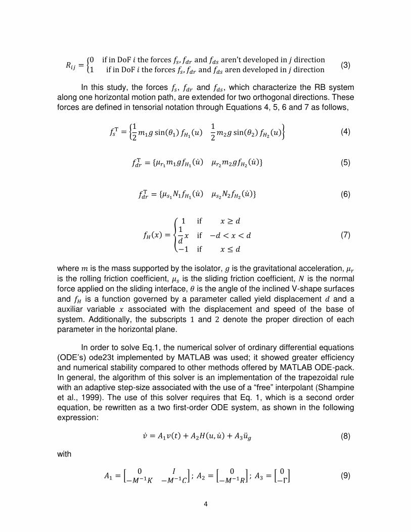
𝑅𝑖𝑗 = {0 if in DoF 𝑖 the forces 𝑓𝑠, 𝑓𝑑𝑟 and 𝑓𝑑𝑠 aren’t developed in 𝑗 direction 1 if in DoF 𝑖 the forces 𝑓𝑠, 𝑓𝑑𝑟 and 𝑓𝑑𝑠 aren developed in 𝑗 direction (3)
In this study, the forces 𝑓𝑠, 𝑓𝑑𝑟 and 𝑓𝑑𝑠, which characterize the RB system
along one horizontal motion path, are extended for two orthogonal directions. These
forces are defined in tensorial notation through Equations 4, 5, 6 and 7 as follows,
𝑓𝑠T = {12 𝑚1𝑔 sin(𝜃1) 𝑓𝐻1(𝑢) 12 𝑚2𝑔 sin(𝜃2) 𝑓𝐻2(𝑢)} (4)
𝑓𝑑𝑟T = {𝜇𝑟1𝑚1𝑔𝑓𝐻1(�̇�) 𝜇𝑟2𝑚2𝑔𝑓𝐻2(�̇�)} (5)
𝑓𝑑𝑟T = {𝜇𝑠1𝑁1𝑓𝐻1(�̇�) 𝜇𝑠2𝑁2𝑓𝐻2(�̇�)} (6)
𝑓𝐻(𝑥) = { 1 if 𝑥 ≥ 𝑑1𝑑 𝑥 if −𝑑 < 𝑥 < 𝑑−1 if 𝑥 ≤ 𝑑 (7)
where 𝑚 is the mass supported by the isolator, 𝑔 is the gravitational acceleration, 𝜇𝑟
is the rolling friction coefficient, 𝜇𝑠 is the sliding friction coefficient, 𝑁 is the normal
force applied on the sliding interface, 𝜃 is the angle of the inclined V-shape surfaces
and 𝑓𝐻 is a function governed by a parameter called yield displacement 𝑑 and a
auxiliar variable 𝑥 associated with the displacement and speed of the base of
system. Additionally, the subscripts 1 and 2 denote the proper direction of each
parameter in the horizontal plane.
In order to solve Eq.1, the numerical solver of ordinary differential equations
(ODE’s) ode23t implemented by MATLAB was used; it showed greater efficiency
and numerical stability compared to other methods offered by MATLAB ODE-pack.
In general, the algorithm of this solver is an implementation of the trapezoidal rule
with an adaptive step-size associated with the use of a “free” interpolant (Shampine
et al., 1999). The use of this solver requires that Eq. 1, which is a second order
equation, be rewritten as a two first-order ODE system, as shown in the following
expression: �̇� = 𝐴1𝑣(𝑡) + 𝐴2𝐻(𝑢, �̇�) + 𝐴3�̈�𝑔 (8)
with 𝐴1 = [ 0 𝐼−𝑀−1𝐾 −𝑀−1𝐶] ; 𝐴2 = [ 0−𝑀−1𝑅] ; 𝐴3 = [ 0−Γ] (9)
5
where, 𝐴1 and �̇�(𝑡)T(= {𝑢 �̇�}) represent the matrix of properties and response
vector of the system in state-state representation. The non-linearity of the system is
represented by 𝐻(𝑢, �̇�) function, which includes the effects of the RB system.
3.Validation of the motion equations
To validate the numerical simulation algorithm, the results of an experimental
evaluation Ortiz-Cano et al. (2015) and a numerical simulation of a building with and
without RB isolation were compared. The characteristics of the building model and
the numerical simulations are described next.
3.1.Building description
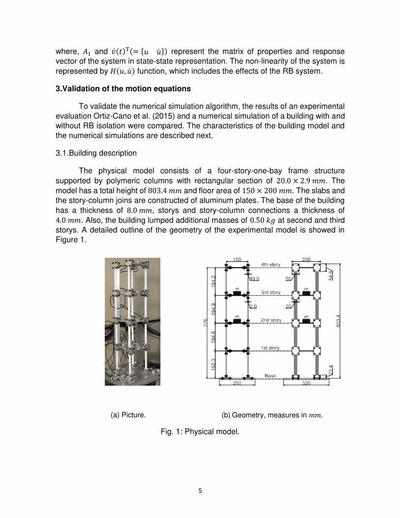
The physical model consists of a four-story-one-bay frame structure
supported by polymeric columns with rectangular section of 20.0 × 2.9 𝑚𝑚. The
model has a total height of 803.4 𝑚𝑚 and floor area of 150 × 200 𝑚𝑚. The slabs and
the story-column joins are constructed of aluminum plates. The base of the building
has a thickness of 8.0 𝑚𝑚, storys and story-column connections a thickness of 4.0 𝑚𝑚. Also, the building lumped additional masses of 0.50 𝑘𝑔 at second and third
storys. A detailed outline of the geometry of the experimental model is showed in
Figure 1.
(a) Picture. (b) Geometry, measures in 𝑚𝑚.
Fig. 1: Physical model.
6
According to the experimental tests carried out and the analysis
methodologies adopted by the author, the modal parameters identified for the fixed-
base building model are summarized in Table 1.
Table 1: Identified dynamic properties of the building.
Mode (Type-Direction) 𝑓𝑒𝑥𝑝(𝐻𝑧) 𝜉𝑒𝑥𝑝 (𝐻𝑧) 1st (Flexural - Weak) 6.82 ± 0.02 0.59 ± 0.03 2nd (Flexural - Weak) 20.44 ± 0.03 0.51 ± 0.01 3rd (Torsional) 21.55 ± 0.02 2.88 ± 0.03 4th (Flexural - Weak) 31.70 ± 0.02 0.30 ± 0.01
In addition, Rayleigh damping constants values of 𝛼 = 4.03 × 10⁻¹ and 𝛽 =5.58 × 10⁻⁵ were determined for the first two modes of vibration (which add up to
95% modal participation of the total mass of the building) because Rayleigh damping
model is used to assembly the damping matrix 𝐶 within the numerical simulation
algorithm.
3.2.RB system description
The seismic behavior of a bidirectional RB isolation system composed mainly
of two surfaces and an array of rollers rolling in an orthogonal arrangement is
investigated. Previous works have shown that the use of these isolation system
enhances the dynamic response of the structure subjected to seismic excitations,
e.g., Ortiz-Cano et al. (2014) and Menga et al. (2017). However, there are certain
drawbacks to this isolation scheme, such as the self-centering mechanism and
rolling bearing support stability (Sanchez-Torres et al., 2019).
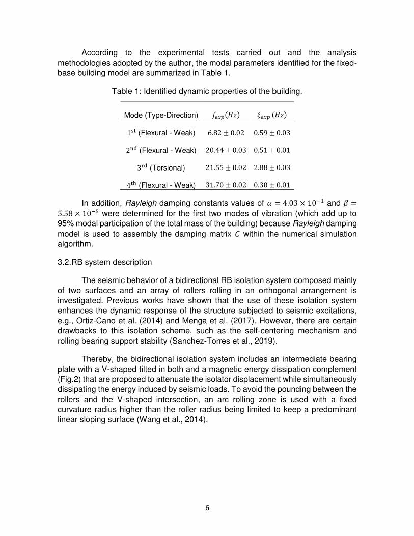
Thereby, the bidirectional isolation system includes an intermediate bearing
plate with a V-shaped tilted in both and a magnetic energy dissipation complement
(Fig.2) that are proposed to attenuate the isolator displacement while simultaneously
dissipating the energy induced by seismic loads. To avoid the pounding between the
rollers and the V-shaped intersection, an arc rolling zone is used with a fixed
curvature radius higher than the roller radius being limited to keep a predominant
linear sloping surface (Wang et al., 2014).
7
Fig. 2: Bidirectional RIS model with magnetic energy dissipation.
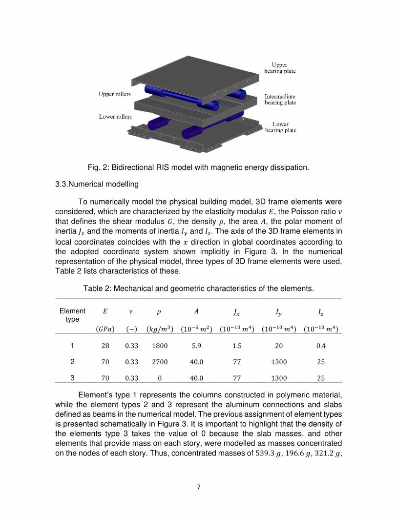
3.3.Numerical modelling
To numerically model the physical building model, 3D frame elements were
considered, which are characterized by the elasticity modulus 𝐸, the Poisson ratio 𝜈
that defines the shear modulus 𝐺, the density 𝜌, the area 𝐴, the polar moment of
inertia 𝐽𝑥 and the moments of inertia 𝐼𝑦 and 𝐼𝑧. The axis of the 3D frame elements in
local coordinates coincides with the 𝑥 direction in global coordinates according to
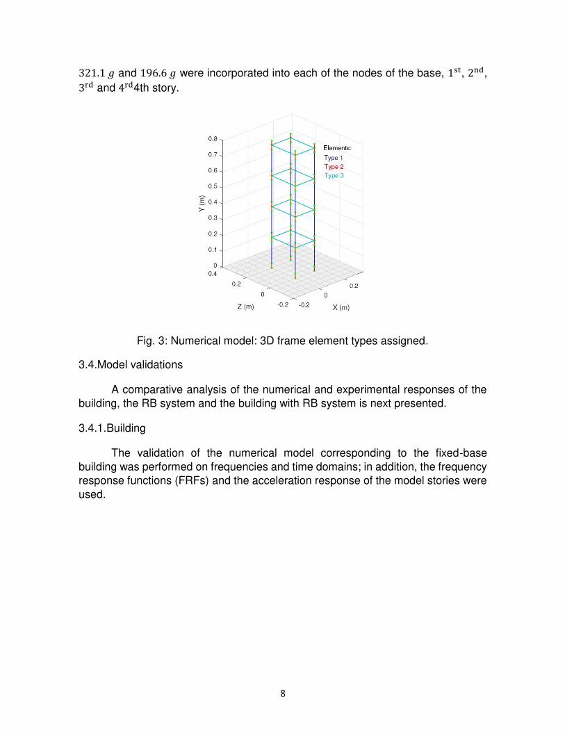
the adopted coordinate system shown implicitly in Figure 3. In the numerical
representation of the physical model, three types of 3D frame elements were used,
Table 2 lists characteristics of these.
Table 2: Mechanical and geometric characteristics of the elements.
Element type
𝐸 𝜈 𝜌 𝐴 𝐽𝑥 𝐼𝑦 𝐼𝑧 (𝐺𝑃𝑎) (−) (𝑘𝑔/𝑚3) (10−5 𝑚2) (10−10 𝑚4) (10−10 𝑚4) (10−10 𝑚4) 1 28 0.33 1800 5.9 1.5 20 0.4
2 70 0.33 2700 40.0 77 1300 25
3 70 0.33 0 40.0 77 1300 25
Element’s type 1 represents the columns constructed in polymeric material,
while the element types 2 and 3 represent the aluminum connections and slabs
defined as beams in the numerical model. The previous assignment of element types
is presented schematically in Figure 3. It is important to highlight that the density of
the elements type 3 takes the value of 0 because the slab masses, and other
elements that provide mass on each story, were modelled as masses concentrated
on the nodes of each story. Thus, concentrated masses of 539.3 𝑔, 196.6 𝑔, 321.2 𝑔,
8
321.1 𝑔 and 196.6 𝑔 were incorporated into each of the nodes of the base, 1st, 2nd, 3rd and 4rd4th story.
Fig. 3: Numerical model: 3D frame element types assigned.
3.4.Model validations
A comparative analysis of the numerical and experimental responses of the
building, the RB system and the building with RB system is next presented.
3.4.1.Building
The validation of the numerical model corresponding to the fixed-base
building was performed on frequencies and time domains; in addition, the frequency
response functions (FRFs) and the acceleration response of the model stories were
used.
9
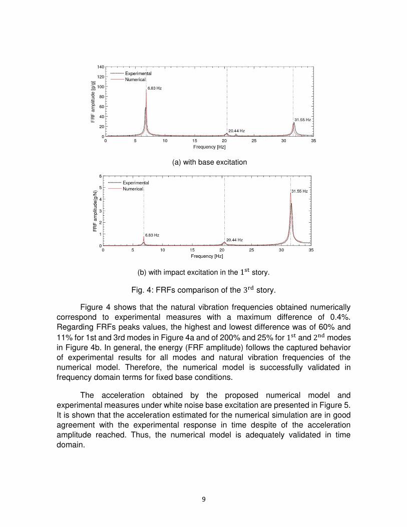
(a) with base excitation
(b) with impact excitation in the 1st story.
Fig. 4: FRFs comparison of the 3rd story.
Figure 4 shows that the natural vibration frequencies obtained numerically
correspond to experimental measures with a maximum difference of 0.4%.
Regarding FRFs peaks values, the highest and lowest difference was of 60% and
11% for 1st and 3rd modes in Figure 4a and of 200% and 25% for 1st and 2nd modes
in Figure 4b. In general, the energy (FRF amplitude) follows the captured behavior
of experimental results for all modes and natural vibration frequencies of the
numerical model. Therefore, the numerical model is successfully validated in
frequency domain terms for fixed base conditions.
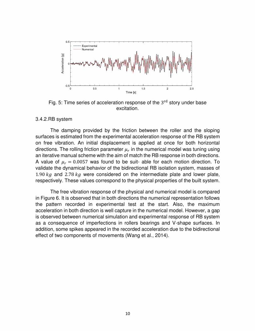
The acceleration obtained by the proposed numerical model and
experimental measures under white noise base excitation are presented in Figure 5.
It is shown that the acceleration estimated for the numerical simulation are in good
agreement with the experimental response in time despite of the acceleration
amplitude reached. Thus, the numerical model is adequately validated in time
domain.
10
Fig. 5: Time series of acceleration response of the 3rd story under base excitation.
3.4.2.RB system
The damping provided by the friction between the roller and the sloping
surfaces is estimated from the experimental acceleration response of the RB system
on free vibration. An initial displacement is applied at once for both horizontal
directions. The rolling friction parameter 𝜇𝑟 in the numerical model was tuning using
an iterative manual scheme with the aim of match the RB response in both directions.
A value of 𝜇𝑟 = 0.0057 was found to be suit- able for each motion direction. To
validate the dynamical behavior of the bidirectional RB isolation system, masses of 1.90 𝑘𝑔 and 2.78 𝑘𝑔 were considered on the intermediate plate and lower plate,
respectively. These values correspond to the physical properties of the built system.
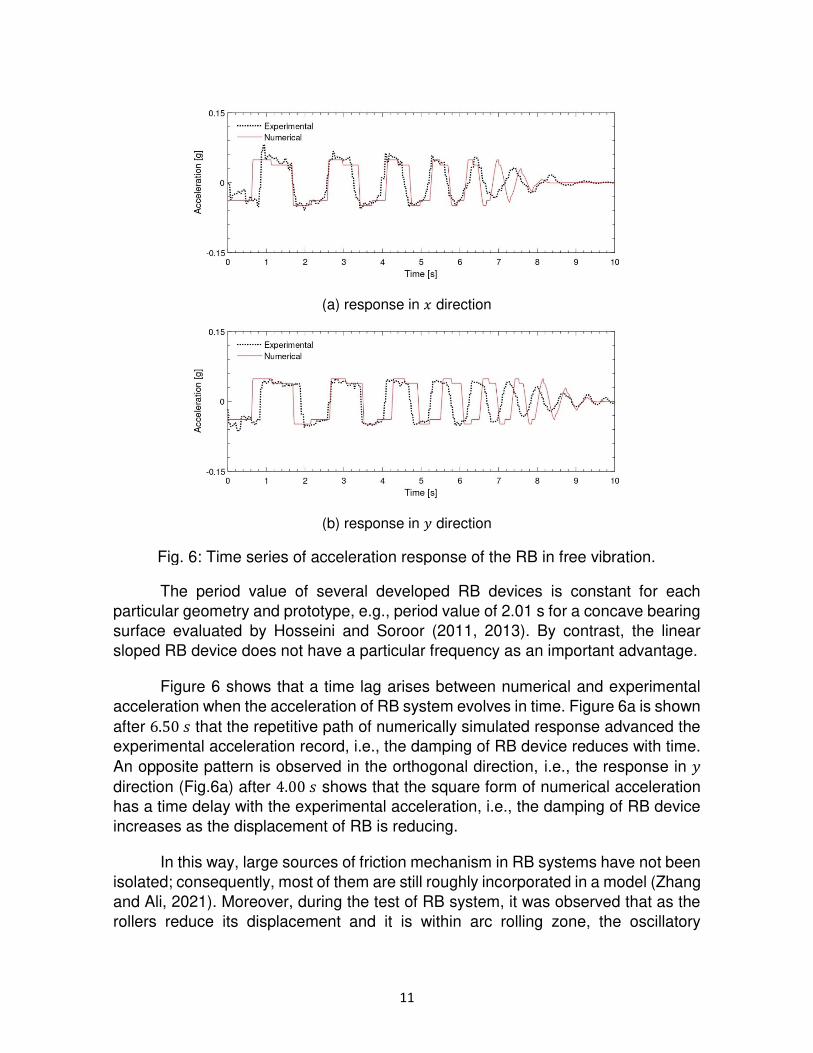
The free vibration response of the physical and numerical model is compared
in Figure 6. It is observed that in both directions the numerical representation follows
the pattern recorded in experimental test at the start. Also, the maximum
acceleration in both direction is well capture in the numerical model. However, a gap
is observed between numerical simulation and experimental response of RB system
as a consequence of imperfections in rollers bearings and V-shape surfaces. In
addition, some spikes appeared in the recorded acceleration due to the bidirectional
effect of two components of movements (Wang et al., 2014).
11
(a) response in 𝑥 direction
(b) response in 𝑦 direction
Fig. 6: Time series of acceleration response of the RB in free vibration.
The period value of several developed RB devices is constant for each
particular geometry and prototype, e.g., period value of 2.01 s for a concave bearing
surface evaluated by Hosseini and Soroor (2011, 2013). By contrast, the linear
sloped RB device does not have a particular frequency as an important advantage.
Figure 6 shows that a time lag arises between numerical and experimental
acceleration when the acceleration of RB system evolves in time. Figure 6a is shown
after 6.50 𝑠 that the repetitive path of numerically simulated response advanced the
experimental acceleration record, i.e., the damping of RB device reduces with time.
An opposite pattern is observed in the orthogonal direction, i.e., the response in 𝑦
direction (Fig.6a) after 4.00 𝑠 shows that the square form of numerical acceleration
has a time delay with the experimental acceleration, i.e., the damping of RB device
increases as the displacement of RB is reducing.
In this way, large sources of friction mechanism in RB systems have not been
isolated; consequently, most of them are still roughly incorporated in a model (Zhang
and Ali, 2021). Moreover, during the test of RB system, it was observed that as the
rollers reduce its displacement and it is within arc rolling zone, the oscillatory
12
movement of rolling bearing system trend to be unbalanced and compromise the
accuracy of numerical modelling.
3.4.3.Building with RB system
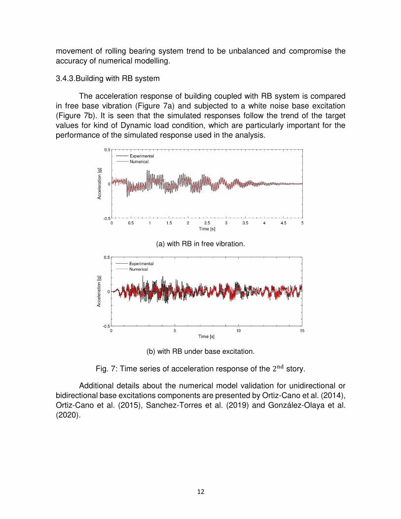
The acceleration response of building coupled with RB system is compared
in free base vibration (Figure 7a) and subjected to a white noise base excitation
(Figure 7b). It is seen that the simulated responses follow the trend of the target
values for kind of Dynamic load condition, which are particularly important for the
performance of the simulated response used in the analysis.
(a) with RB in free vibration.
(b) with RB under base excitation.
Fig. 7: Time series of acceleration response of the 2nd story.
Additional details about the numerical model validation for unidirectional or
bidirectional base excitations components are presented by Ortiz-Cano et al. (2014),
Ortiz-Cano et al. (2015), Sanchez-Torres et al. (2019) and González-Olaya et al.
(2020).
13
4.RB system performance under near-fault earthquakes
In this section, the performance of the RB system in reducing the structural
response of buildings subjected to a particular seismic excitation is evaluated
through an extensive numerical study. In this study, two isolated structures with
different configurations of the RB system were simulated when subjected to the
horizontal components of two near fault seismic records.
The two structures considered are the product of the partial modification of
the validated numerical model to obtain: (I) an S1 structure in which the vibration
frequencies of its first two modes are less than 2.0 𝐻𝑧; and (II) an S2 structure in
which the vibration frequencies of its first two modes are greater than 10.0 𝐻𝑧,
representing buildings with low and high lateral stiffness, respectively. The
modification was made by affecting the inertias 𝐼𝑦 and 𝐼𝑧 of the elements type 1. For
the S1 structure 𝐼𝑦 was reduced to 3.0 × 10⁻¹² 𝑚4 and 𝐼𝑧 to 2.0 × 10⁻¹² 𝑚4, while for
the S2 structure 𝐼𝑦 was reduced to 1.0 × 10⁻¹⁰ 𝑚4 and 𝐼𝑧 was increased to 1.0 ×10⁻¹⁰ 𝑚4. Thus, Table 3 shows the predominant frequencies of the modified
structures that correspond to the first three modes of vibration.
Table 3: Modes and frequencies of vibration of structures S1 and S2.
Mode (Type-Direction) Frequency (𝐻𝑧)
S1 S2 1st (Flexural - Weak) 1.51 10.21 2nd (Flexural - Weak) 1.85 10.30 3rd (Torsional) 3.09 10.73
Near fault seismic events are generally characterized by exhibiting a long-
duration, large-magnitude displacement pulse with large accelerations and limited
frequencies content compared to far fault earthquakes. Given these characteristics
of ground displacement and acceleration, large lateral displacements are expected
in base seismic isolation systems when they are subjected to this type of excitation,
which results in an inefficient system. Therefore, it can be stated that the most critical
operating condition for base isolation systems is when these seismic events occur.
Considering the above, the present numerical study uses near fault earth-
quake horizontal records to evaluate the performance of RB in the most un-
favorable base excitation conditions. Table 4 presents the selected near fault seismic
records obtained from PEER Ground Motion Database (Ancheta et al., 2013).
Vertical ground motions components are not used because it has a negligible effect
14
performance of different isolation devices (Ou et al., 2010; Beirami-Shahabi et al.,
2019).
Table 4: Near fault earthquake records.
Data Earthquake
Event name Northridge – 01 Imperial Valley – 06
Date January 17, 1994 October 15, 1979
Record Newhall – Fire Station El Centro – Array #5
Component 90 360 140 230
PGD (𝑐𝑚) 17.6 34.3 48.9 75.2
PGA (𝑔) 0.566 0.590 0.529 0.383
Since S1 and S2 are defined from a physical model, the selected seismic
records are scaled in displacement amplitude to 5% of their PGD to conserve the
magnitudes. Real records were scaled using the Make Quake program from
Quanser Consulting Inc. (2010) that implements the scaling algorithm developed by
Kausel and Ushijima (1979) and that allows to preserve both the accelerations
magnitude and frequencies content of the original records.
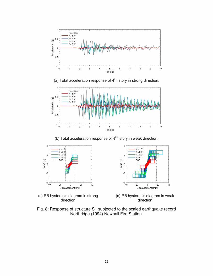
First, the S1 and S2 structures were simulated subjected to scale excitations
under fixed base conditions. Then, they were simulated incorporating the RB
systems considering four angles of inclination of the V-shaped surfaces: 1°, 2°, 3° and 4°. Thus, in Figures 8 and 9 the acceleration response of th4the story and the
hysteresis diagram of the RB system are presented for each structure and base
excitation.
In these figures it is observed that all the configurations manage to reduce the
structural response of S1 and S2. System efficiency increases as the angle of
inclined surfaces decreases, achieving a reduction in peak acceleration from 80% to
95% with the lowest angle of inclination. For S2 the reduction is appreciably greater
when compared to S1 for all the evaluated inclinations. Additionally, for S2 the
increase in response reduction varies slightly with the angle of inclination. In terms
of base displacements, it is observed that these also decrease as the inclination of
the inclined surfaces decreases, however, these displacements are excessive since
they are equal to or greater than scaled peak ground displacement (PGD), Figures
8c, 8d, 9c and 9d.
15
(a) Total acceleration response of 4th story in strong direction.
(b) Total acceleration response of 4th story in weak direction.
(c) RB hysteresis diagram in strong direction
(d) RB hysteresis diagram in weak direction
Fig. 8: Response of structure S1 subjected to the scaled earthquake record Northridge (1994) Newhall Fire Station.
16
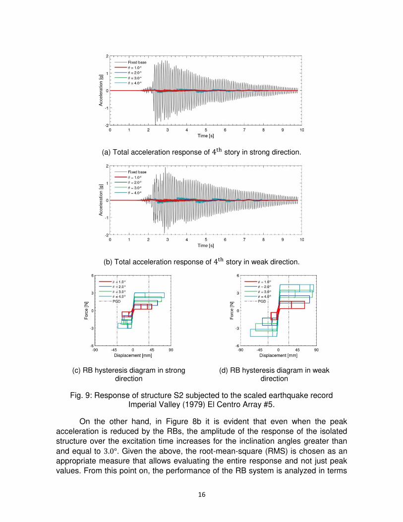
(a) Total acceleration response of 4th story in strong direction.
(b) Total acceleration response of 4th story in weak direction.
(c) RB hysteresis diagram in strong direction
(d) RB hysteresis diagram in weak direction
Fig. 9: Response of structure S2 subjected to the scaled earthquake record Imperial Valley (1979) El Centro Array #5.
On the other hand, in Figure 8b it is evident that even when the peak
acceleration is reduced by the RBs, the amplitude of the response of the isolated
structure over the excitation time increases for the inclination angles greater than
and equal to 3.0°. Given the above, the root-mean-square (RMS) is chosen as an
appropriate measure that allows evaluating the entire response and not just peak
values. From this point on, the performance of the RB system is analyzed in terms
17
of the RMS for each of the simulations carried out. The effectiveness in controlling
the structural response with the RB system is quantified through the following
expression: 𝐶𝐸[%] = 𝜎𝑢 − 𝜎𝑐𝜎𝑢 (10)
Where 𝜎𝑐 and 𝜎𝑢 are the RMS values of the structural response with and without the
RB system, respectively. Furthermore, 𝜎𝑐 and 𝜎𝑢 for each story of the structure is
calculated as the vector sum of RMS value in each horizontal directions of motion,
i.e.,√𝜎𝑥2 + 𝜎𝑧2.
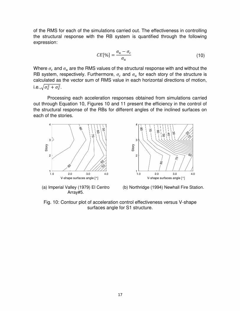
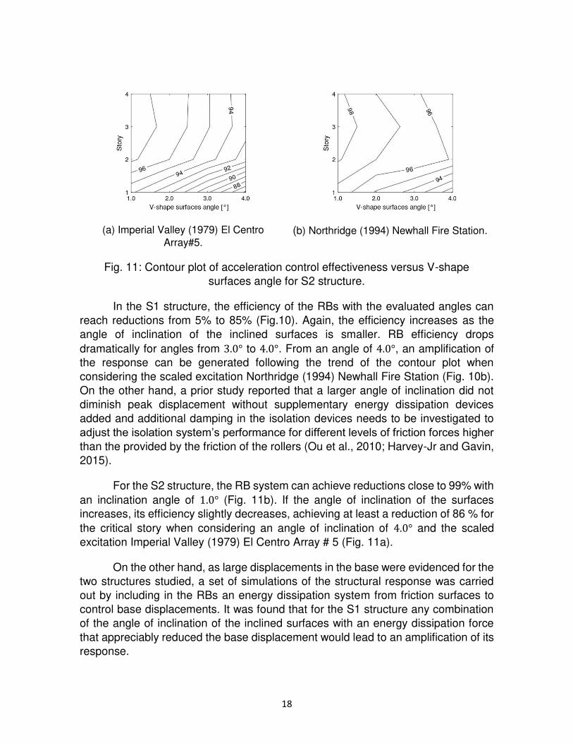
Processing each acceleration responses obtained from simulations carried
out through Equation 10, Figures 10 and 11 present the efficiency in the control of
the structural response of the RBs for different angles of the inclined surfaces on
each of the stories.
(a) Imperial Valley (1979) El Centro Array#5.
(b) Northridge (1994) Newhall Fire Station.
Fig. 10: Contour plot of acceleration control effectiveness versus V-shape surfaces angle for S1 structure.
18
(a) Imperial Valley (1979) El Centro
Array#5. (b) Northridge (1994) Newhall Fire Station.
Fig. 11: Contour plot of acceleration control effectiveness versus V-shape
surfaces angle for S2 structure.
In the S1 structure, the efficiency of the RBs with the evaluated angles can
reach reductions from 5% to 85% (Fig.10). Again, the efficiency increases as the
angle of inclination of the inclined surfaces is smaller. RB efficiency drops
dramatically for angles from 3.0° to 4.0°. From an angle of 4.0°, an amplification of
the response can be generated following the trend of the contour plot when
considering the scaled excitation Northridge (1994) Newhall Fire Station (Fig. 10b).
On the other hand, a prior study reported that a larger angle of inclination did not
diminish peak displacement without supplementary energy dissipation devices
added and additional damping in the isolation devices needs to be investigated to
adjust the isolation system’s performance for different levels of friction forces higher than the provided by the friction of the rollers (Ou et al., 2010; Harvey-Jr and Gavin,
2015).
For the S2 structure, the RB system can achieve reductions close to 99% with
an inclination angle of 1.0° (Fig. 11b). If the angle of inclination of the surfaces
increases, its efficiency slightly decreases, achieving at least a reduction of 86 % for
the critical story when considering an angle of inclination of 4.0° and the scaled
excitation Imperial Valley (1979) El Centro Array # 5 (Fig. 11a).
On the other hand, as large displacements in the base were evidenced for the
two structures studied, a set of simulations of the structural response was carried
out by including in the RBs an energy dissipation system from friction surfaces to
control base displacements. It was found that for the S1 structure any combination
of the angle of inclination of the inclined surfaces with an energy dissipation force
that appreciably reduced the base displacement would lead to an amplification of its
response.
19
In the S2 structure, a significant reduction in structural response together with
an appreciable reduction in base displacements can be achieved by combining
inclination angles greater than 4.0◦. If smaller angles are used, self- centering
capacity of the system would be compromised, and non-recoverable base
displacements would be generated at the end of the excitation. In general, the
restoring force produced by the inclination of the V-shaped surfaces should not be
exceeded by the dissipation force developed in the friction plates since the re-
centering force at the end of the excitation would be insufficient to overcome the
force of friction of the dissipation system.
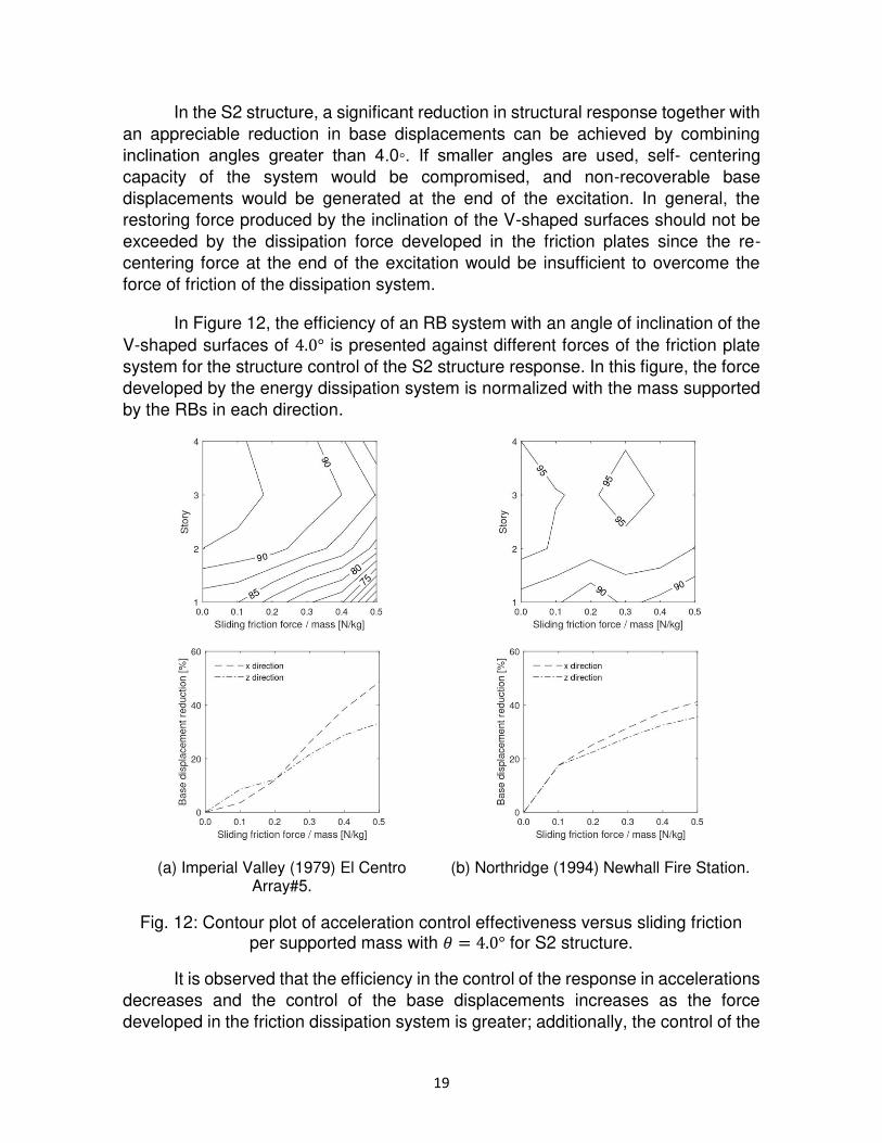
In Figure 12, the efficiency of an RB system with an angle of inclination of the
V-shaped surfaces of 4.0° is presented against different forces of the friction plate
system for the structure control of the S2 structure response. In this figure, the force
developed by the energy dissipation system is normalized with the mass supported
by the RBs in each direction.
(a) Imperial Valley (1979) El Centro Array#5.
(b) Northridge (1994) Newhall Fire Station.
Fig. 12: Contour plot of acceleration control effectiveness versus sliding friction per supported mass with 𝜃 = 4.0° for S2 structure.
It is observed that the efficiency in the control of the response in accelerations
decreases and the control of the base displacements increases as the force
developed in the friction dissipation system is greater; additionally, the control of the
20
base displacements increases more slowly as sliding friction force is greater. Figures
12a and 12a are shown that the maximum displacement reached by the sloped
rolling rod base isolator is related to the peak ground accelerations of the earthquake
motion, i.e., the lowest performance is achieved when the structure is subject to
Imperial Valley (1979) El Centro Array #5 scale record, when it is designed with a
larger sloping angle and a higher sliding friction force/mass as has been recently
reported, e.g., Wang et al. (2019).
Given the above, a suitable combination that achieves the greatest reduction
in the response of the structure with the minimum base displacement can be
achieved by varying the inclination of the V-shaped surfaces and the energy
dissipation force. For the case of the analyzed structure, with the maximum control
of the base displacement, the response in accelerations of the structure can be
reduced in each of its floors from 60% to 87% in the most critical condition base
excitation, i.e., Northridge (1994) Newhall Fire Station.
5.Conclusions
This paper presents an extensive numerical study to evaluate the
performance of the RB system in reducing the structural response of multi-column
systems subjected to the horizontal components of near-fault earthquake records.
The reduction of the structural response was evaluated through direct comparison
and the RMS statistical measure between the simulation results under fixed base
conditions and using the RB system. Thus, the following conclusions are drawn from
the present study:
1. The RB system manages to significantly reduce the response of the evaluated
structures when subjected to near-fault earthquake excitations. Direct
comparison shows reductions in peak acceleration of up to 80% for the
flexible structure and 98% for the rigid structure. In terms of the RMS
measurement, acceleration reductions of 5% to 85% are achieved for the
flexible structure, while in the rigid structure reductions of 86% to 96% are
achieved.
2. In the rigid structure the efficiency of the RB system is significantly higher than
in the flexible structure, however, there are base displacements equal to or
greater than the earthquake ground peak displacement in both cases.
3. One way to control the displacements generated at the base is the use of
energy dissipation systems. In the numerical study, frictional energy
dissipation systems were simulated; they were able to reduce approximately
35% of the base displacements and guarantee at least a 60% RMS reduction
in the total acceleration of the rigid structure. For the flexible structure it was
found that a reduction in the base displacements will inevitably lead to the
amplification of the response with respect to the fixed base condition, which
21
indicates that using this displacement control system is not suitable for this
particular situation.
4. It is recommended to use friction systems for energy dissipation on surfaces
that are sufficiently inclined to guarantee an appropriate self-centering
capacity of the RB system. In the numerical study, it was found that angles
less than or equal to 3.0° generated residual displacements at the base due
to loss of self-centering capacity for the rigid structure.
5. An adequate relationship between the angle of the inclined surfaces and the
parameters associated with the energy dissipation system will result in a
maximum reduction in the response of total acceleration with the minimum
base displacement for a particular building and a set of seismic excitations.
Several aspects of the use of RB systems in multi-column structures were
studied and presented; however, this work opens the door to future research, both
numerical and experimental. Some future aspects that can be addressed are:
1. Experimentally validate the results obtained numerically for a reduced and a
full scale.
2. Consider vertical accelerations effects induced by seismic excitation and by
the behavior of the roller bearings.
3. Evaluate numerically and experimentally the use of RB in non-symmetric
structural systems whose predominant vibration modes of vibration are
torsional type.
4. Develop an energy dissipation system that reduce the base displacements
with a minimum impact on the control efficiency of total acceleration of the
buildings.
Acknowledgments
This research was supported by the Office Vice-Provost for Research at
Universidad Militar Nueva Granada under grant number INV-ING-2982, this support
is gratefully acknowledged.
References
Ancheta T, Darragh R, Stewart J, Seyhan E, Silva W, Chiou B, Wooddell K, Graves
R, Kottke A, Boore D, Kishida T, Donahue J. (2013). PEER NGA-West2 Database.
Tech. Rep. PEER 2013/03, Pacific Earthquake Engineering Research Center
(PEER), PEER Core Institutions, Berkeley, CA, USA.
Andreaus U, De Angelis M. (2020). Influence of the characteristics of isolation and
mitigation devices on the response of single-degree-of-freedom vibro-impact
systems with two-sided bumpers and gaps via shaking table tests. Structural Control
and Health Monitoring 27(5):e2517.
22
Bagerzadeh-Karimi M, Geneş M. (2019). Probabilistic behavior assessment of base-
isolated buildings and base isolation systems subjected to various earthquakes with
different components. Arabian Journal for Science and Engineering 44(10):8265–8288.
Beirami-Shahabi A, Zamani-Ahari G, Barghian M. (2019). Suspended columns for
seismic isolation in structures (SCSI): A preliminary analytical study. Earthquakes
and Structures 16(6):743–755.
Beirami-Shahabi A, Zamani-Ahari G, Barghian M (2020) Base isolation sys- tems: A
state of the art review according to their mechanism. Journal of Rehabilitation in Civil
Engineering 8(2):37–61
Brewick P, Johnson E, Sato E, Sasaki T. (2020). Modeling the dynamic behavior of
isolation devices in a hybrid base-isolation layer of a full-scale building. Journal of
Engineering Mechanics 146(11):04020127.
Calhoun S. (2018). Evaluation of rolling-type isolation systems for seismic hazard
mitigation. Master’s thesis, The University of Oklahoma, Norman, OK, USA.
Calhoun S, Tehrani M, Harvey-Jr P. (2019). On the performance of double rolling
isolation systems. Journal of Sound and Vibration 449:330–348.
Chen P, Hsu S, Zhong Y, Wang S. (2021). Real-time hybrid simulation of smart base-
isolated raised floor systems for high-tech industry. Smart Structures and Systems
23(1):91–106
Erdik M, Ulker O, Şadan B, Tuzun C. (2018). Seismic isolation code developments
and significant applications in Turkey. Soil Dynamics and Earthquake Engineering
115:413–437.
González-Olaya R, Ortiz-Cano N, Nieto-Leal A, Gaviria-Mendoza C. (2020).
Numerical performance evaluation of a bi-directional roller seismic isolation
bearings. In: 11th International Conference on Structural Dynamics, European
Association for Structural Dynamics.
Harvey-Jr P, Gavin H. (2015). Assessment of a rolling isolation system using
reduced order structural models. Engineering Structures 99:708–725.
Hosseini M, Soroor A. (2011). Using orthogonal pairs of rollers on concave beds
(OPRCB) as a base isolation system Part I: Analytical, experimental and numerical
studies of (OPRCB) isolators. The Structural Design of Tall and Special Buildings
20:928–950.
23
Hosseini M, Soroor A. (2013). Using orthogonal pairs of rollers on concave beds
(OPRCB) as a base isolation system Part II: Application to multi-story and tall
buildings. The Structural Design of Tall and Special Buildings 22:192–216.
Kausel E, Ushijima R. (1979). Baseline correction of earthquake records in the
frequency domain. Tech. Rep. R79-34, Massachusetts Institute of Technology,
Cambridge, MA, USA.
Lee G, Ou Y, Niu T, Song J, Liang Z. (2010). Characterization of a roller seismic
isolation bearing with supplemental energy dissipation for highway bridges. Journal
of Structural Engineering 136(5):502–510.
Matsagar V, Jangid R. (2008). Base isolation for seismic retrofitting of structures.
Practice periodical on structural design and construction 13(14):175– 185.
Menga N, Foti D, Carbone G. (2017). Viscoelastic frictional properties of rubber-layer
roller bearings (RLRB) seismic isolators. Meccanica 52:2807–2817.
Naeim F, Kelly J (1999) Design of seismic isolated structures: From theory to
practice. Wiley & Sons, New York, USA.
Ortiz-Cano N, Magluta C, Roitman N. (2014). Numerical and experimental studies
of a building with elastomeric and roller seismic isolation bearing. In: 9th International
Conference on Structural Dynamics, European Association for Structural Dynamics.
Ortiz-Cano N, Magluta C, Roitman N. (2015). Numerical and experimental studies
of a building with roller seismic isolation bearings. Structural Engineering &
Mechanics 54(3):475–489.
Ou Y, Song J, Lee G. (2010). A parametric study of seismic behavior of roller seismic
isolation bearings for highway bridges. Earthquake Engineering & Structural
Dynamics 39(5):541–559.
Quanser Consulting Inc. (2010). Make Quake Program.
Rawat A, Matsagar V. (2021). An oblate spheroid base isolator and floating surface
diaphragm for seismic protection of liquid storage tank. Journal of Earthquake
Engineering pp 1–29.
Rawat A, Ummer N, Matsagar V. (2018). Performance of bi-directional elliptical
rolling rods for base isolation of buildings under near-fault earthquakes. Advances in
Structural Engineering 21(5):675–693.
Ryan K, Okazaki T, Coria C, Sato E, Sasaki T. (2018). Response of hybrid isolation
system during a shake table experiment of a full-scale isolated building. Earthquake
Engineering and Structural Dynamics 47:2214–2232.
24
Sanchez-Torres D, Rico-Caviedes A, Ortiz-Cano N, Nieto-Leal A, Gaviria- Mendoza
C. (2019). Assessment of a roller seismic isolation bearing for buildings under
bidirectional excitations. In: XL Ibero-Latin-American Congress on Computational
Methods in Engineering, Brazilian Association of Computational Methods in
Engineering.
Shampine L, Reichelt M, Kierzenka J. (1999). Solving Index-1 DAEs in MATLAB and
Simulink. SIAM Review 18(3):538–552.
The MathWorks Inc. (2019). MATLAB R2019a.
Tsai M, Wu S, Chang K, Lee G. (2007) Shaking table tests of a scaled bridge model
with rolling-type seismic isolation bearings. Engineering Structures 29:694–702.
Walters M. (2015). Seismic isolation: The gold standard of seismic protection. In:
Structural Performance, Structure Magazine.
Wang S, Hwang J, Chang K, Shiau C, Lin W, Tsai M, Hong J, Yang Y. (2014). Sloped
multi-roller isolation devices for seismic protection of equipment and facilities.
Earthquake Engineering & Structural Dynamics 43:1443–1461.
Wang S, Lin W, Yang C, Chang Y K Huang, Hwang J, Hwang J. (2017). Recent
progress in Taiwan on seismic isolation, energy dissipation, and active vibration
control. In: 15th World Conference on Seismic Isolation, Energy Dissipation, and
Active Vibration Control of Structures, New Zealand Society for Earthquake
Engineering, Anti-seismic Systems International Society.
Wang S, Yu C, Cho C, Hwang J. (2019). Effects of design and seismic parameters
on horizontal displacement responses of sloped rolling-type seismic isolators.
Structural Control and Health Monitoring 26(5):e2342.
Wang S, Sung Y, Yang C, Lin W, Yu C. (2020). Control performances of friction
pendulum and sloped rolling-type bearings designed with single parameters. Applied
Sciences 10(20):7200.
Zhang C, Ali A. (2021). The advancement of seismic isolation and energy dissipation
mechanisms based on friction. Soil Dynamics and Earthquake Engineering
146:106746.