Pompe Chimie Centrifuge Typ/Type RCE · 3 Die Konstruktion Horizontale,1-stufige...
18
RHEINHÜTTE PUMPEN Chemie-Kreiselpumpe Chemical Centrifugal Pump Pompe Chimie Centrifuge Typ/Type RCE
Transcript of Pompe Chimie Centrifuge Typ/Type RCE · 3 Die Konstruktion Horizontale,1-stufige...

RHEINHÜTTEP U M P E N
Chemie-KreiselpumpeChemical Centrifugal PumpPompe Chimie Centrifuge
Typ/Type RCE
2
Die EinsatzgebieteMit der Chemie-Kreiselpumpe Typ RCEwerden Förderprobleme in der gesamtenchemischen Industrie, der Grundstoffin-dustrie, der Umwelttechnik und vielen an-deren Industriezweigen gelöst.
Die RCE-Kreiselpumpe überschreitetdurch Konzeption und robuste Ausfüh-rung wesentlich den Einsatzbereich derChemie-Normpumpe.
Die RCE als Standardpumpe und pro-duktbezogene Spezialversion bewährtsich seit Jahrzehnten bei normalem undbei schwerem Betrieb zum Fördern vonanorganischen und organischen, aggres-siven Flüssigkeiten mit oder ohne Fest-stoffanteilen.
Beispiele sind Ammoniumnitrat, Natron-lauge, Schwefelsäure, Oleum, flüssigerSchwefel, Wasserglas, Phosphorsäure,Maischen, Teer, Pech, Kataphoreselacke,Harnstoffschmelze und Gaswäscher-Flüssigkeiten…
ApplicationsThe chemical centrifugal pump type RCEis a heavy duty design particularly for usein the chemical, raw material, environ-mental pollution control and many otherindustries.
The RCE pump, by virtue of its design cri-teria and robust construction, greatly ex-ceeds the application area of the DIN /ISO standard chemical pump.
The RCE pump has proven very success-ful for many decades, used in standarddesign form or product related specialdesign. It is used for both easy and difficultapplications handling inorganic and orga-nic aggressive liquids with and withoutsolids.
Typical applications areas are AmmoniumNitrate, Caustic Soda, Sulphuric Acid,Oleum, Liquid Sulphur, Sodium, Silicate,Phosphoric Acid, Tar, Pitch, CataphoreticPaints, Urea melt, Gas Scrubbing Liquorsetc.…
Domaine d‘emploiLa pompe chimie centrifuge type RCEpermet de résoudre les problèmes depompage des industries chimiques, ma-tières premières, pour la protection del‘environnement, et bien d‘autres domai-nes.
Grâce à sa conception et à sa granderobustesse, la pompe RCE couvre etdépasse les domaines d‘emploi des pom-pes normalisées.
La pompe RCE a fait ses preuves depuisdes dizaines d‘années, aussi bien en ver-sion de base qu‘en version spécialeadaptée au produit. Elle est utilisée dansdes conditions normales ou difficiles pourvéhiculer des liquides minéraux ou orga-niques plus ou moins agressifs, avec ousans particules solides en suspension.
Quelques exemples: nitrate d‘ammonium,soufre liquide, brai et goudrons, urée,peinture cataphorèse, acide et bouilliephosphorique, jus de lavage de gaz, acidesulfurique, oléum, eaux mères…
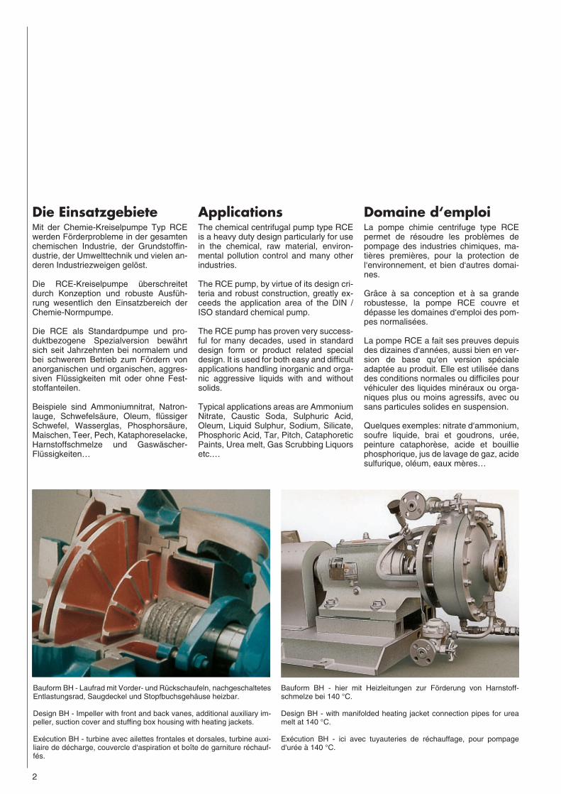
Bauform BH - Laufrad mit Vorder- und Rückschaufeln, nachgeschaltetesEntlastungsrad, Saugdeckel und Stopfbuchsgehäuse heizbar.
Design BH - Impeller with front and back vanes, additional auxiliary im-peller, suction cover and stuffing box housing with heating jackets.
Exécution BH - turbine avec ailettes frontales et dorsales, turbine auxi-liaire de décharge, couvercle d‘aspiration et boîte de garniture réchauf-fés.
Bauform BH - hier mit Heizleitungen zur Förderung von Harnstoff-schmelze bei 140 °C.
Design BH - with manifolded heating jacket connection pipes for ureamelt at 140 °C.
Exécution BH - ici avec tuyauteries de réchauffage, pour pompaged‘urée à 140 °C.

3
Die Konstruktion
● Horizontale,1-stufige Spiralgehäuse-pumpe mit besonders robust ausgeleg-tem Lagerbock.
● Konstruiert nach dem Baukastenprin-zip. Ca. 40 Pumpengrößen an 5 Lager-böcken.
● Breite Werkstoffpalette. Konstruktivunterteilt in drei Gruppen:– niedriglegierte, hochlegierte undreinste Gußwerkstoffe– Eisensiliziumguß (mit Panzer)– Grauguß / gummiert
● Beachtliche Wanddickenzuschläge fürKorrosion und Abrasion
● Pumpenteile aus unterschiedlichenWerkstoffen kombinierbar bzw. gegen-einander austauschbar. Dadurch opti-male Anpassungen an extreme Be-triebsbedingungen
● Auf die Belange der Kreiselpumpe füraggressive und abrasive Flüssigkeitenabgestimmte, optimale Strömungsge-schwindigkeiten. Die Werte sind beiRCE wesentlich niedriger als bei Pum-pen mit Normabmessungen
● Große Spalte zwischen rotierenden Teilen und Gehäuseteilen. Verminder-ter Verschleiß, keine Gefahr des Lauf-rad-Anlaufens.
● Geringer Verschleiß in der Pumpe be-wirkt konstante Förderleistungen über lange Zeiträume.
● Bei verschiedenen Baugrößen Spiral-gehäuse mit Doppelspirale zum Aus-gleich der Radialkräfte
● Axialschubausgleich erfolgt durch Vor-der und Rückschaufeln.
● Im Standardfall mit geschlossenenLaufrädern. Offene Laufräder lieferbar.
● Inducer zur Reduzierung des NPSH-Wertes und Vermeidung von Kavitationeinbaubar.
● Hydrodynamische Wellenabdichtung inden Bauformen B und D. Bauform Dmit zusätzlicher Stillstandsabdichtung.Seit Jahrzehnten bewährte Systeme
Design Features
● Horizontal, single stage centrifugalpump with heavy duty bearing pedestal
● The principal of modular design resultsin the benefit of approximately 40 pump sizes with only 5 bearing pedestal si-zes
● Wide range of materials available wit-hin 3 basic design groups:– low alloyed, high alloyed and un-alloyed cast materials– silicon cast iron (with armoured hou-sing) rubber lined cast iron
● Extra wall thickness for increased corrosion and abrasion allowance
● Extreme operating conditions can behandled by using a combination of dif-ferent materials within one pump. Thisallows optimum solutions for arduous pumping applications
● Optimum flow velocities taking intoconsideration the corrosive and abrasi-ve properties of liquids. Flow velocitiesfor the RCE are considerably lowerthan comparable DIN/ISO standar-dized pumps.
● Wide clearances between rotating andstationary parts result in reduced wear with no risk of impeller fouling.
● Low wear in the pump results in no fall-off in pump performance over a long period of time.
● Many sizes with double spiral volute tobalance radial forces.
● Axial thrust is balanced by impellerfront and back vanes.
● Standard design with closed impeller.Open impeller available.
● Inducers to reduce NPSH values andto avoid cavitation are available.
● Hydrodynamic shaft sealing in designB and D. Design D with additional sta-tionary shaft sealing arrangement. All designs proven for decades.
Particularités de construction● Pompe horizontale monocellulaire avec
chaise de palier particulièrement robuste.
● Construite en éléments modulaires.Environ 40 tailles sur 5 chaises depaliers.
● Large palette de matériaux répartis en3 groupes:– matériaux de fonderie légèrement al-liés, fortement alliés, ou nobles– fontes au silicium (corps avec blindage)– fonte caoutchoutée
● Fortes surépaisseurs de corrosion et d‘abrasion
● Pièces de pompe en différents maté-riaux, interchangeables. La combinai-son de plusieurs marériaux permet une adaptation optimale aux conditions de service extrêmes.
● Faible vitesse du fluide en rapport avecle caractère agressif et abrasif des produits véhiculés. Valeur très inféri-eure à celle des pompes normalisées.
● Jeux de fonctionnement importantsréduisant l‘usure et le risque de grippage de la turbine.
● La pompe étant moins sensible à l‘abrasion, les caractéristiques depompage se modifient plus lentement.
● Pour certaines tailles de pompes, volu-te à double spirale afin d‘équilibrer lespoussées radiales.
● Eqilibrage de poussées axiales par lesailettes frontales et dorsales des turbines
● Exécution standard avec turbine fer-mée.Turbine ouverte sur demande.
● En cas de risque de cavitation,possibilité d‘installer une turbine degavage (inducer) pour diminuer le NPSHrequis.
● Etanchéité d‘arbre hydrodynamiquepour les exécutions B et D. Etanchéité supplémentaire automatique à l‘arrêt pour l‘exécution D. Systèmes éprouvés depuis plusieurs dizaines d‘années.

4
● Wellenabdichtung Bauform C mittelsEinzel -, Doppel- oder Tandem-Gleit-ringdichtungen verschiedener Fabrika-te.
● Austauschbarkeit der Wellenabdich-tungsbauformen gegeneinander
● Wellenabdichtungskonzept läßt auchEinbau von anderen Abdichtelementenoder Abdichtsystemen zu, z.B. pneu-matische Stillstandsabdichtung oderFettschloß-Stillstandsabdichtung.
● Je nach Betriebsbedingungen ist Keil-riemenantrieb mit oder ohne Zwischen-welle möglich.
● Heizbare Ausführung für Flüssigkeitendie bei Umgebungstemperaturen er-starren oder auskristallisieren
● Schmierung der Wälzlager im Lager-bock mit Fett. Ölschmierung für beson-dere Betriebsbedingungen
● Lagerbock wird auch in sandsturm-sicherer Ausführung gebaut
● Stark dimensionierte Welle und kräftigeWellenlagerung im besonders robu-sten Lagerbock (kein Lagerträger) ga-rantieren ruhigen, schwingungsarmenLauf. Dadurch je nach PumpengrößeBetrieb mit Drehzahlen bis 3500 1/min(60 Hz) zulässig
● Flanschbearbeitung nach DIN. Anpas-sung an internationale Standards mög-lich.
● Drehrichtung (vom Antrieb aus gese-hen) links.
Die Druck- undTemperaturgrenzen
● Design C features shaft sealing withmechanical seals of various makes insingle, double or back to back arrange-ment
● Interchangeability of different types ofshaft sealing arrangement
● Shaft sealing concept allows the use ofother sealing elements or systems egpneumatic statonary seal or grease-lock stationary seal.
● V-belt drive arrangement possible withor without intermediate shaft - depen-ding on operating conditions
● Heating jacket design available forliquids which solidify or crystallise atambient temperature
● Grease lubricated antifriction bea-rings– oil lubrication available for spe-cial operating conditions
● Sand storm-safe bearing housing de-sign available
● Heavy shaft and bearing design gua-rantees quiet and low vibration operati-on. Therefore, depending on pump si-ze, operation at speeds up to 3500 rpm(60 Hz) permissible
● Flanges drilled according to most inter-national standards
● Direction of rotation (viewed from driveend) ccw.
Pressure andTemperature Ratings
● Etanchéité d‘arbre exécution C par gar-nitures mécaniques simples, doublesou en tandem, de différentes marques
● Interchangeabilité entre les différentssystèmes d‘étanchéité d‘arbre
● Conception du système d‘étanchéitéautorisant l‘installation d‘autres élé-ments ou systèmes, par exemple étan-chéité pneumatique à l‘arrêt, étan-chéité à l‘arrêt par blocage à la grais-se.
● Suivant les conditions de service, pos-sibilité d‘entraînement par poulies-courroies, avec ou sans arbre intermé-diaire
● Exécution avec enveloppe de réchauf-fage pour fluides qui figent ou cristalli-sent à température ambiente
● De façon standard, lubrification à lagraisse des roulements de la chaise depalier. Pour cas particuliers, lubrificati-on à l‘huile.
● Variante avec chaise de palier étancheaux tempêtes de sable
● Arbre et roulements largement dimen-sionnés montés dans une chaise depalier (et non un corps de palier) ga-rantissant un fonctionnement sansbruit ni vibrations. En fonction de la tail-le de la pompe, des vitesses de 35001/min (60 Hz) sont ainsi possibles
● Brides usinées suivant les normesAFNOR et DIN. Adaptation possibleaux standards internationnaux
● Sens de rotation: gauche (vu côté ac-couplement)
Limites de pressionet de température
Druck max. 25 bar*
Temperatur -40 °C bis +450 °C
Pressure max. 25 bar*
Temperature -40 °C to +450 °C
Pression maxi 25 bar*
Température -40 °C à +450 °C
* je nach Pumpenausführung und Werkstoff *depending on pump design and material * suivant exécution de la pompe et matériaux
5
Hydrodynamische Wellenabdichtung undStillstandsabdichtungDie hydrodynamische Wellenabdichtungin den Bauformen B und D einschließlichVarianten macht die RCE-Pumpe fürkomplizierteste Förderaufgaben, beson-ders im Hochtemperaturbereich und beimAbsaugen aus Vakuum, interessant.
Beiden Bauformen gemein ist die hydro-dynamische Entlastung des Wellendurch-tritts während des Betriebes. Die Pumpensind tropffrei dicht.
Während im Stillstand bei der Bauform Beine Stopfbuchspackung nach außen ab-dichtet, übernimmt bei der Bauform D einmechanisch betätigtes Ringventil, beste-hend aus Wellenhülse (Pos. 523) undDichtungseinsatz (Pos. 443), diese Dicht-funktion.
Beim Einschalten der Pumpe werden dieSchwungkörper (Pos 616) des Regulatorsim Lagerbock nach außen geschleudert.Sie bewirken ein Verschieben der Welle(Pos. 210) samt allen rotierenden Teilenzum Saugstutzen hin. Das Ringventil öff-net.
Wird die Pumpe ausgeschaltet, ziehenFedern (Pos. 614.950) im Regulator dieWelle zurück. Das Ringventil schließt unddichtet im Stillstand nach außen hin ab.
In den Übergangsphasen beim Ein- undAusschalten kann die Hydrodynamik nochnicht oder nicht mehr voll wirksam sein.Kleine Flüssigkeitsmengen können aus-treten.Sie werden im Raum hinter demRingventil mittels Spritzring (Pos 507.1)gezielt erfaßt und durch das Ablaufrohrmit Flanschübergang (Pos.722) abge-führt.
Hydrodynamic ShaftSeal with StationarySealing ArrangementThe hydrodynamic shaft seal in the varia-tions of B and D design makes the RCEpump particularly suitable for difficult du-ties especially for high temperature or lowsuction pressure applications
Both pump designs utilise the principle ofhydrodynamic relief of the gland duringoperation. The pumps are leak-free.
During stationary periods, design B uses apacked gland to seal to atmosphere,whilst the seal in design D is achieved bymeans of a mechanically operated ringvalve comprising shaft sleeve (part no.523) and seal insert (part no. 443).
When the pump runs up to speed , the go-vernor weights (part no. 616) in the bea-ring pedestal are thrown outwards undercentrifugal force, resulting in limited axialmovement of the shaft assembly (part no.210). This movement, in the direction ofthe suction nozzle, opens the ring valve.
When the pump stops, the springs (partno. 614.950) located in the governorweight assembly move the shaft back andthe ring valve closes, ensuring a positiveseal to atmosphere during stationary peri-ods.
During starting (run-up) and stopping (run-down) periods, the hydrodynamic reliefcannot be fully effective. Small amounts ofliquid may escape which are collected inthe area behind the ring valve by means ofthe thrower (part no. 507.1) and drainedthrough the flanged taperpiece (part no.722).
Etanchéité d‘arbre hydrodynamique etétanchéité à l‘arrêtL‘étanchéité d‘arbre hydrodynamique desexécutions B, D, et de leurs variantes, faitde la pompe RCE une solution égalementintéressante aux problèmes de pompageles plus compliqués, notamment dans ledomaine des hautes températures et pourl‘extraction sous vide.
L‘étanchéité hydrodynamique pendant lefonctionnement est commune aux deuxexécutions. Aucune fuite de liquide par lepassage d‘arbre.
Alors que l‘étanchéité à l‘arrêt est assuréepar un presse-étoupe à tresses dansl‘exécution B, celle-ci est assurée dansl‘exécution D par une soupape annulairecommandée mécaniquement et com-posée de la chemise d‘arbre (rep. 523) etdu flasque de garniture (rep. 443)
Au démarrage de la pompe, les masse-lottes (rep.616) du régulateur placé dansla chaise de palier sont centrifugées versl‘extérieur. Elles provoquent un déplace-ment simultané de l‘arbre (rep.210) et detoutes les parties tournantes vers la brided‘aspiration. La soupape annulaire s‘ou-vre.
A l‘arrêt de la pompe, les ressorts (rep.614.950) du régulateur tirent l‘arbre versl‘arrière. La soupape annulaire se ferme etassure l‘étanchéité à l‘arrêt.
Pendant les phases transitoires de dé-marrage et d‘arrêt, il est possible que ladécharge hydrodynamique ne soit pas en-core ou plus totalement efficace. Une pe-tite quantité de liquide peut alors sortir. Celiquide est retenu dans la chambre à l‘ar-rière de la soupape annulaire par ledéflecteur (rep.507.1), et est canalisé parle tube de récupération et la bride (rep.722)
6
RCE mit hydrodynamischer WellenabdichtungRCE with Hydrodynamic Shaft SealingRCE avec étanchéité d‘arbre hydrodynamique
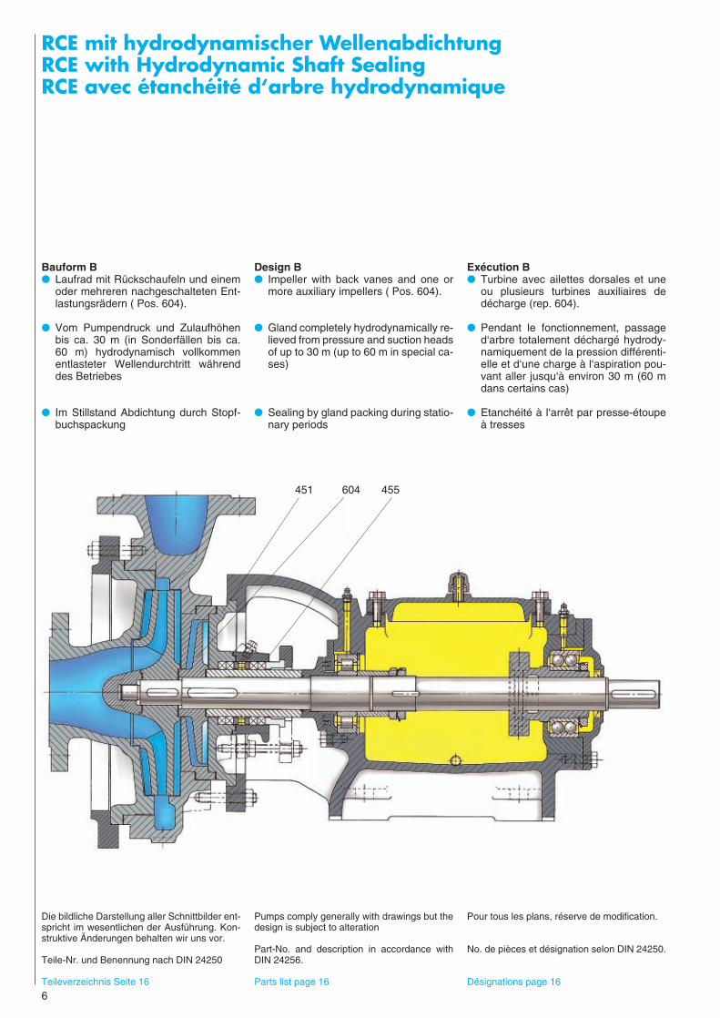
Bauform B● Laufrad mit Rückschaufeln und einem
oder mehreren nachgeschalteten Ent-lastungsrädern ( Pos. 604).
● Vom Pumpendruck und Zulaufhöhenbis ca. 30 m (in Sonderfällen bis ca.60 m) hydrodynamisch vollkommenentlasteter Wellendurchtritt währenddes Betriebes
● Im Stillstand Abdichtung durch Stopf-buchspackung
Design B● Impeller with back vanes and one or
more auxiliary impellers ( Pos. 604).
● Gland completely hydrodynamically re-lieved from pressure and suction headsof up to 30 m (up to 60 m in special ca-ses)
● Sealing by gland packing during statio-nary periods
Exécution B● Turbine avec ailettes dorsales et une
ou plusieurs turbines auxiliaires dedécharge (rep. 604).
● Pendant le fonctionnement, passaged‘arbre totalement déchargé hydrody-namiquement de la pression différenti-elle et d‘une charge à l‘aspiration pou-vant aller jusqu‘à environ 30 m (60 mdans certains cas)
● Etanchéité à l‘arrêt par presse-étoupeà tresses
Die bildliche Darstellung aller Schnittbilder ent-spricht im wesentlichen der Ausführung. Kon-struktive Änderungen behalten wir uns vor.
Teile-Nr. und Benennung nach DIN 24250
Teileverzeichnis Seite 16
Pumps comply generally with drawings but thedesign is subject to alteration
Part-No. and description in accordance withDIN 24256.
Parts list page 16
Pour tous les plans, réserve de modification.
No. de pièces et désignation selon DIN 24250.
Désignations page 16
451 604 455

RCE mit hydrodynamischer WellenabdichtungRCE with Hydrodynamic Shaft SealingRCE avec étanchéité d‘arbre hydrodynamique
7
Bauform D● Funktion während des Betriebes ent-
sprechend Bauform B.
● Im Stillstand Abdichtung durch Ring-ventil, bestehend aus Wellenhülse(Pos. 523) und Dichtungseinsatz (Pos.443). Nachgeschaltete kurze Stopf-buchse erschwert Austritt von Gasenund Dämpfen
● Das Ringventil wird durch Schwung-körper (Pos. 616) vom Lagerbock ausüber die axial verschiebbare Wellebetätigt
Design D● Pressure relief of gland during opera-
tion same as for Design B.
● During stationary periods, shaft sealingis achieved by means of a ring valvecomprising shaft sleeve (Pos. 523) andinsert (Pos. 443). A short secondarygland packing reduces the possibility ofescape of vapour
● Governor weights (Pos. 616) mountedin the bearing pedestal activate the ringvalve by means of axial movement ofthe rotating shaft.
Exécution D● Fonctionnement en marche identique à
l‘exécution B.
● Etanchéité à l‘arrêt par soupape annu-laire se composant de la chemise d‘ar-bre (rep. 523) et du flasque de garni-ture (rep. 443). Presse-étoupe courtréduisant les fuites de gaz ou vapeursdégagées par le fluide
● Soupape annulaire commandée par unsystème centrifuge à masselottes(rep.616) placé dans la chaise de palieret provoquant un déplacement axial del‘arbre
Teileverzeichnis Seite 16 Parts list page 16 Désignations page 16
635 523 450
443 616
8
RCE mit hydrodynamischer WellenabdichtungRCE with Hydrodynamic Shaft SealingRCE avec étanchéité d‘arbre hydrodynamique
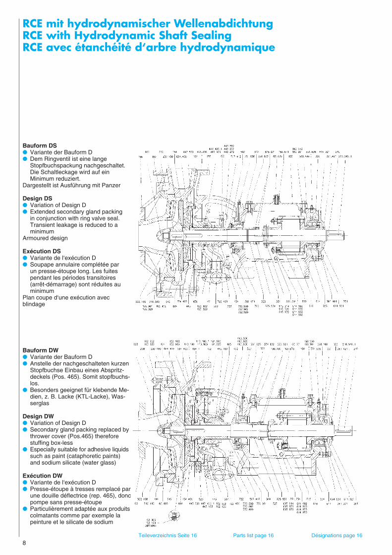
Bauform DS● Variante der Bauform D● Dem Ringventil ist eine lange
Stopfbuchspackung nachgeschaltet.Die Schaltleckage wird auf ein Minimum reduziert.
Dargestellt ist Ausführung mit Panzer
Design DS● Variation of Design D● Extended secondary gland packing
in conjunction with ring valve seal.Transient leakage is reduced to a minimum
Armoured design
Exécution DS● Variante de l‘exécution D● Soupape annulaire complétée par
un presse-étoupe long. Les fuites pendant les périodes transitoires (arrêt-démarrage) sont réduites au minimum
Plan coupe d‘une exécution avec blindage
Bauform DW● Variante der Bauform D● Anstelle der nachgeschalteten kurzen
Stopfbuchse Einbau eines Abspritz-deckels (Pos. 465). Somit stopfbuchs-los.
● Besonders geeignet für klebende Me-dien, z. B. Lacke (KTL-Lacke), Was-serglas
Design DW● Variation of Design D● Secondary gland packing replaced by
thrower cover (Pos.465) thereforestuffing box-less
● Especially suitable for adhesive liquidssuch as paint (cataphoretic paints)and sodium silicate (water glass)
Exécution DW● Variante de l‘exécution D● Presse-étoupe à tresses remplacé par
une douille déflectrice (rep. 465), doncpompe sans presse-étoupe
● Particulièrement adaptée aux produitscolmatants comme par exemple lapeinture et le silicate de sodium
Teileverzeichnis Seite 16 Parts list page 16 Désignations page 16

9
Bauform DWH● Variante der Bauform DW, Saugdeckel
(Pos.162) und Dichtungseinsatz (Pos.443) heizbar. Pumpe stopfbuchslos.
● Standardausführung z. B. für flüssigenSchwefel
● Einsatzspezifisch mit oder ohneeingepreßtem PTFE-Ring imDichtungseinsatz lieferbar
Design DWH● Variation of design DW with heating
jackets on suction cover (Pos.162) andseal insert (Pos. 443), stuffingboxless.
● Standard design for molten sulphur● Either with or without a PTFE ring
pressed into the seal insert.
Exécution DWH● Variante de l‘exécution DW, avec
réchauffage du couvercle d‘aspiration(rep.162) et du flasque de garniture(rep.443). Exécution sans presse-étoupe .
● Exécution standard pour le soufreliquide par exemple
● Suivant les applications, exécutionlivrable avec ou sans anneau PTFEserti dans le flasque de garniture.
Einzel-GleitringdichtungBauform C1H● Bevorzugt Norm-Ausführung nach
DIN 24960 (CN 1). Nicht entlastetoder entlastet
● Innen- oder Außenzirkulation derKühl- und Schmierflüssigkeit
● Dargestellt ist die Ausführung mitInnenzirkulation und beheiztemDichtungsdeckel
Single Mechanical Seal Design C1H● Seals with norm-dimensions to DIN
24960 preferred (CN 1 design) unbalanced or balanced
● Internal or external circulation ofcooling and lubricating liquids
● The design with internal circulationand heated seal cover is illustrated
Garniture mécanique simpleExécution C1H● De préférence normalisée suivant
NF E 29-991 et DIN 24960 (CN 1),compensée ou non
● Circulation interne ou externe du liquidede refroidissement ou de lubrification
● Représentation d’une exécution aveccirculation interne et couvercle de gar-niture réchauffé. Teileverzeichnis Seite 16 Parts ist page 16 Désignation page 16
10
RCE mit GleitringdichtungRCE with Mechanical SealRCE avec garniture mécanique
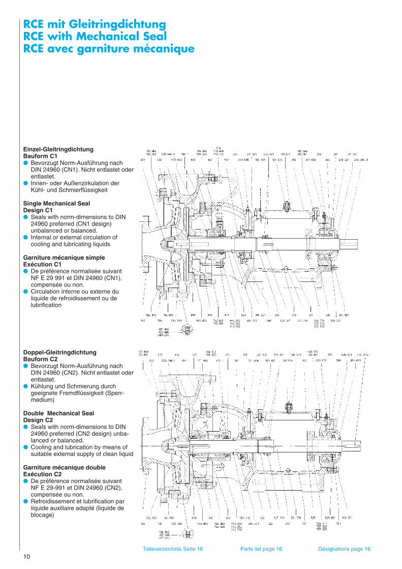
Einzel-GleitringdichtungBauform C1● Bevorzugt Norm-Ausführung nach
DIN 24960 (CN1). Nicht entlastet oderentlastet.
● Innen- oder Außenzirkulation derKühl- und Schmierflüssigkeit
Single Mechanical SealDesign C1● Seals with norm-dimensions to DIN
24960 preferred (CN1 design) unbalanced or balanced.
● Internal or external circulation ofcooling and lubricating liquids
Garniture mécanique simpleExécution C1● De préférence normalisée suivant
NF E 29 991 et DIN 24960 (CN1),compensée ou non.
● Circulation interne ou externe du liquide de refroidissement ou de lubrification
Doppel-GleitringdichtungBauform C2● Bevorzugt Norm-Ausführung nach
DIN 24960 (CN2). Nicht entlastet oderentlastet.
● Kühlung und Schmierung durchgeeignete Fremdflüssigkeit (Sperr-medium)
Double Mechanical SealDesign C2● Seals with norm-dimensions to DIN
24960 preferred (CN2 design) unba-lanced or balanced.
● Cooling and lubrication by means ofsuitable external supply of clean liquid
Garniture mécanique doubleExécution C2● De préférence normalisée suivant
NF E 29-991 et DIN 24960 (CN2),compensée ou non.
● Refroidissement et lubrification parliquide auxiliaire adapté (liquide deblocage)
Teileverzeichnis Seite 16 Parts list page 16 Désignations page 16
RCE mit GleitringdichtungRCE with Mechanical SealRCE avec garniture mécanique
11
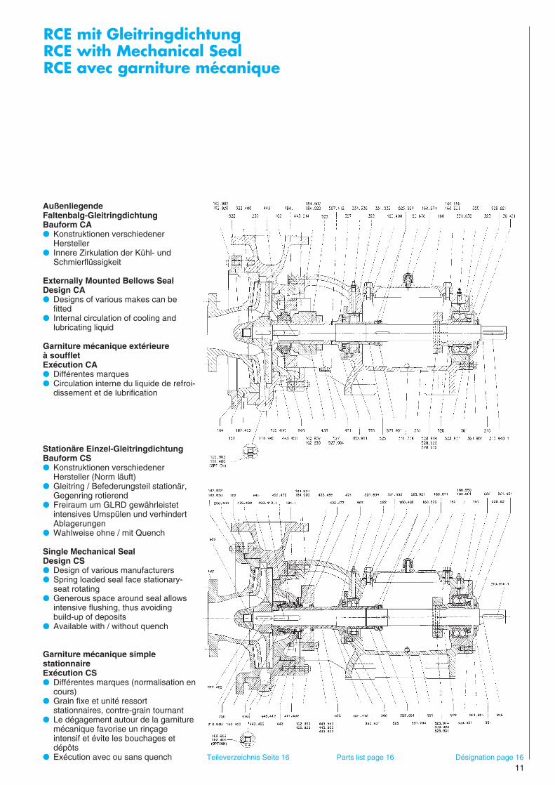
AußenliegendeFaltenbalg-GleitringdichtungBauform CA● Konstruktionen verschiedener
Hersteller● Innere Zirkulation der Kühl- und
Schmierflüssigkeit
Externally Mounted Bellows Seal Design CA● Designs of various makes can be
fitted● Internal circulation of cooling and
lubricating liquid
Garniture mécanique extérieure à souffletExécution CA● Différentes marques● Circulation interne du liquide de refroi-
dissement et de lubrification
Stationäre Einzel-GleitringdichtungBauform CS● Konstruktionen verschiedener
Hersteller (Norm läuft)● Gleitring / Befederungsteil stationär,
Gegenring rotierend● Freiraum um GLRD gewährleistet
intensives Umspülen und verhindertAblagerungen
● Wahlweise ohne / mit Quench
Single Mechanical SealDesign CS● Design of various manufacturers● Spring loaded seal face stationary-
seat rotating● Generous space around seal allows
intensive flushing, thus avoiding build-up of deposits
● Available with / without quench
Garniture mécanique simple stationnaireExécution CS● Différentes marques (normalisation en
cours)● Grain fixe et unité ressort
stationnaires, contre-grain tournant● Le dégagement autour de la garniture
mécanique favorise un rinçageintensif et évite les bouchages etdépôts
● Exécution avec ou sans quench Teileverzeichnis Seite 16 Parts list page 16 Désignation page 16

12
EinbaumaßeDimensionsEncombrement
Drehrichtung vom Antrieb aus gesehen linksDirection of rotation CCW viewed from drive endSens de rotation à gauche, vu côté accouplement
Lagerbock I II III IV IVBearing pedestal verstChaise de palier reinf.
renf.
d 25 35 45 60 65
l 45 65 65 95 130
t 27,9 38,3 48,5 64,2 69,2
u 8 10 14 18 18
Flanschmaße ohne Panzer mit PanzerFlange dimensions without armour with armourCotes des brides sans enveloppe avec enveloppeDIN 2501 PN 10 (NF E 29 901)
DN D d4 k d2 n D d4
32 140 78 100 18 4 150 58
40 150 88 110 18 4 165 65
50 165 102 125 18 4 175 80
65 185 122 145 18 4 185 95
80 200 138 160 18 8 210 110
100 220 158 180 18 8 230 140
125 250 188 210 18 8 265 165
150 285 212 240 23 8 295 190
200 340 268 295 23 8 – –
250 395 320 350 23 12 – –
300 445 370 400 23 12 – –
Wellenende nach / Shaft end to / Bout d‘arbre selon DIN 748Paßfeder nach / Key to / Clavette selon DIN 6885 /1
a f
lDN FettanschlußGrease connectionRaccord de graisse
EntlüftungVentPurge d’air
DN
h 3
mf1
m1
s1 s2
p
r q
n 1
c e
g k
Entleerung G 1/4DrainVidange
u
d
t
D
øk
d4DN
nxød2
h 2h 1 h 4

EinbaumaßeDimensionsEncombrement
13
32/130 I X X32/160 I X X X40/130 I X X40/160 I X X40/200 I X X X40/260 II X X X50/130 I X X50/160 I X X X50/200 II X X50/260 II X X65/160 I X X65/200 II X X65/260 II X X65/80/360 III X80/160 II X X80/200 II X X X80/260 II X X X80/320 III X X X100/200 II X100/260 III X X X100/320 III X X100/380 IV100/430 IV125/260 III X X125/320 III X125/380 IV150/260 III X X150/320 IV X X150/380 IV X200/320 IV X200/380 IV200/430 IV250/320 IV X250/380 IV verst. X250/430 IV reinf. X300/430 IV renf. X
Größe Lager-bock
Size Bearing pedestal
Modèle Chaise de palier
a f c e f1 g k h1 h2 h3 h4 m m1 n1 p q r s1 s2
105 505 240 90 135 130 165 125 125 240 190 150 18105 505 240 90 135 130 175 125 145 240 190 150 18105 505 240 90 135 130 165 125 135 240 190 150 18105 505 240 90 135 130 175 125 150 240 190 150 18130 505 240 90 135 130 200 125 170 240 190 150 18 150 610 285 130 195 175 225 160 210 290 245 190 23 120 510 240 90 135 130 175 125 145 240 190 150 18120 510 240 90 135 130 185 125 155 240 190 150 18150 610 285 130 195 175 200 160 170 290 245 190 23150 610 285 130 195 175 225 160 210 290 245 190 23130 510 240 90 135 130 200 125 165 240 190 150 18160 610 285 130 195 175 225 160 200 290 245 190 23160 610 285 130 195 175 250 160 220 290 245 190 23170 820 420 175 260 235 295 205 270 365 310 250 26160 610 285 130 195 175 200 160 170 290 245 190 23160 610 285 130 195 175 225 160 200 290 245 190 23160 610 285 130 195 175 250 160 230 290 245 190 23200 800 420 175 260 235 275 205 250 365 310 250 26160 610 285 130 195 175 250 160 200 290 245 190 26200 800 420 175 260 235 275 205 260 365 310 250 26200 800 420 175 280 260 235 275 300 205 270 85 230 365 225 310 250 26 26200 1000 510 230 320 320 290 300 325 225 300 85 240 455 315 400 320 26 26200 1000 510 230 340 320 290 325 350 225 340 80 260 455 315 400 320 26 26200 800 420 175 260 235 300 205 260 365 310 250 26200 800 420 175 280 260 235 300 325 205 280 85 235 365 225 310 250 26 26200 1000 510 230 340 320 290 300 350 225 315 95 275 455 295 400 320 26 26210 820 420 175 280 260 235 275 325 205 270 80 230 365 225 310 250 26 26200 1000 510 230 340 320 290 300 350 225 290 95 270 455 295 400 320 26 26210 990 510 230 340 320 290 300 375 225 315 95 275 455 295 400 320 26 26220 1000 510 230 340 320 290 300 400 225 310 95 270 455 295 400 320 26 26240 980 510 230 340 320 290 325 450 225 335 100 270 455 275 400 320 26 26240 980 510 230 340 320 290 350 500 225 365 100 280 455 275 400 320 26 26250 980 510 230 340 320 290 350 450 225 340 100 270 455 275 400 320 26 26250 980 510 230 340 320 290 350 525 225 350 100 270 455 275 400 320 26 26250 980 510 230 340 320 290 350 550 225 370 100 280 455 275 400 320 26 26250 970 510 230 340 320 290 450 550 225 385 120 270 455 275 400 320 26 26
Größen 300/480 und 400/540 am LagerträgerEinbaumaße auf Anfrage
Maße unverbindlich
Sizes 300/480 and 400/540mounted on bearing bracketDimensions on request
Dimensions subject to change without notice
Modèles 300/480 et 400/540sur corps de palierDimensions sur demande
Cotes sans engagement
Pumpenmaße / Pump Dimensions / Cotes de pompe
Eisensiliziumguß / Silicon Iron Alloys / Alliages ferro-silicium
GG - gummiert / Rubber lined Cast Iron / Fonte caoutchoutée
Ohne Füße am Spiralgehäuse / Without volute foot support / Pompes sans support sous la volute
14
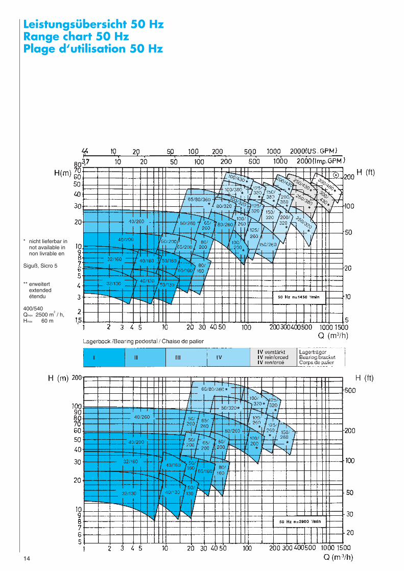
Leistungsübersicht 50 HzRange chart 50 HzPlage d‘utilisation 50 Hz
* nicht lieferbar in not available innon livrable en
Siguß, Sicro 5
** erweitertextendedétendu
400/540Qmax 2500 m
2/ h,
Hmax 60 m

Leistungsübersicht 60 HzRange chart 60 HzPlage d‘utilisation 60 Hz
15
16
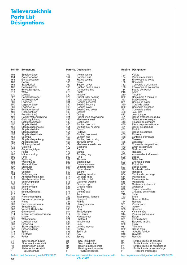
TeileverzeichnisParts ListDésignations
Teil-Nr. Bennenung Part-No. Designation Repère Désignation
102 Spiralgehäuse 102 Volute casing 102 Volute154 Zwischenwand 154 Partition wall 154 Paroi intermédiaire155 Gehäusepanzer 155 Frame casing 155 Enveloppe de corps160 Deckel 160 Cover 160 Couvercle162 Saugdeckel 162 Suction cover 162 Couvercle d‘aspiration166 Deckelpanzer 166 Suction head armour 166 Enveloppe de couvercle184 Befestigungsring 184 Connecting ring 184 Bague de fixation210 Welle 210 Shaft 210 Arbre230 Laufrad 230 Impeller 230 Turbine322 Radialrollenlager 322 Radial roller bearing 322 Roulement à rouleaux323 Axialkugellager 323 Axial ball bearing 323 Butée à billes331 Lagerbock 331 Bearing pedestal 331 Chaise de palier350 Lagergehäuse 350 Bearing housing 350 Corps de palier360 Lagerdeckel 360 Bearing cover 360 Couvercle de palier361 Endlagerdeckel 361 Bearing end cover 361 Couvercle arrière400 Flachdichtung 400 Gasket 400 Joint plat412 Runddichtring 412 O-ring 412 Joint torique421 Radial-Wellendichtring 421 Radial shaft sealing ring 421 Bague d‘étanchéité radial433 Gleitringdichtung 433 Mechanical seal 433 Garniture mécanique443 Dichtungseinsatz 443 Seal insert 443 Flasque de garniture450 Stopfbuchsteil 450 Stuffing box part 450 Pièce de presse-étoupe451 Stopfbuchsgehäuse 451 Stuffing box housing 451 Boîtier de garniture452 Stopfbuchsbrille 452 Gland 452 Fouloir454 Stopfbuchsring 454 Follower 454 Bague de serrage455 Stopfbuchseinsatz 455 Stuffing box insert 455 Fourreau458 Sperring 458 Lantern ring 458 Lanterne d‘arrosage461 Stopfbuchspackung 461 Stuffing box packing 461 Tresses465 Abspritzdeckel 465 Thrower cover 465 Collecteur471 Dichtungsdeckel 471 Mechanical seal cover 471 Couvercle de garniture472 Gleitring 472 Seal ring 472 Grain de garniture476 Gegenringträger 476 Carrier 476 Grain support477 Feder 477 Spring 477 Ressort485 Mitnehmerring 485 Rotating ring 485 Anneau d’entraînement500 Ring 500 Ring 500 Bague507 Spritzring 507 Thrower 507 Déflecteur523 Wellenhülse 523 Shaft sleeve 523 Chemise d‘arbre525 Abstandhülse 525 Distance sleeve 525 Entretoise527 Stellhülse 527 Locating sleeve 527 Bague d‘arrêt528 Bundhülse 528 Coller sleeve 528 Douille de palier550 Scheibe 550 Washer 550 Rondelle604 Entlastungsrad 604 Auxiliary impeller 604 Turbine de décharge614 Abhebescheibe, fest 614 Lift plate fixed 614 Plateau fixe615 Abhebescheibe, lose 615 Lift plate mobil 615 Plateau mobile616 Schwungkörper 616 Governor weights 616 Masselotte635 Fettbuchse 635 Grease cup 635 Graisseur à réservoir636 Schmiernippel 636 Grease nipple 636 Graisseur670 Belüftung 670 Venting 670 Tuyau de reniflard671 Belüftungshaube 671 Venting cap 671 Chapeau de reniflard710 Rohr 710 Tube 710 Tube722 Flanschübergang 722 Taperpiece, flanged 722 Bride731 Rohrverschraubung 731 Pipe joint 731 Raccord filetée734 Fitting 734 Fitting 734 Raccord901 Sechskantschraube 901 Hexagon screw 901 Vis six pans902 Stiftschraube 902 Stud 902 Goujon903 Verschlußschraube 903 Plug 903 Bouchon904 Gewindestift 904 Threaded pin 904 Vis sans tête914 Innen-Sechskantschraube 914 Cyl. screw 914 Vis à six pans creux920 Mutter 920 Hexagon nut 920 Ecrou921 Wellenmutter 921 Shaft nut 921 Ecrou d‘arbre922 Laufradmutter 922 Impeller nut 922 Ecrou de turbine930 Sicherung 930 Lock 930 Frein931 Sicherungsblech 931 Locking washer 931 Tôle frein932 Sicherungsring 932 Circlip 932 Bague frein933 Splint 933 Splint pin 933 Goupille fendue940 Paßfeder 940 Key 940 Clavette950 Feder 950 Spring 950 Ressort
B1 Sperrmedium-Eintritt B1 Seal liquid inlet B1 Entrée liquide de blocageB0 Sperrmedium-Austritt B0 Seal liquid outlet B0 Sortie liquide de blocageH1 Heizmedium-Eintritt H1 Heating medium inlet H1 Entrée liquide de réchauffageH0 Heizmedium-Austritt H0 Heating medium outlet H0 Sortie liquide de réchauffageF Spülanschluß F Flush connection F Raccord d‘arrosage
Teil-Nr. und Benennung nach DIN 24250 Part-No. and description in accordance. with No. de pièces et désignation selon DIN 24250DIN 24250

WerkstoffeMaterialsMatériaux
17
FRIATEC - Rheinhütte - Werkstoff - For-schung, moderne Edelstahlgießerei undQualitätssicherung bilden die Grundlagenfür ein weites Spektrum von korrosions-beständigen und / oder verschleißfestenGußwerkstoffen, aus denen RCE-Pum-pen hergestellt werden.
FRIATEC-Rheinhütte-Material Researchtogether with a modern stainless steelfoundry and a comprehensive Quality As-surance system form the basis of a widespectrum of corrosion and abrasion resi-stant cast materials used in the productionof RCE pumps.
FRIATEC-Rheinhütte posséde son proprelaboratoire de recherche, sa fondrie mo-derne et son service-qualité, representantles bases d‘un large éventail de matériauxrésistants à la corrosion et / ou à l‘abra-sion, et dont profite la pompe RCE
Weitere Werkstoffe auf Anfrage Further materials on request Autres matériaux sur demande
Werkstoff-Bezeichnung (DIN 17006) Werkstoff-Nr. (DIN 17007) Rheinhütte Werkstoff-Bezeichnung ohne Panzer mit PanzerMaterial designation (DIN 17006) Material No. (DIN 17007) Rheinhütte material designation without armour with armourDésignation matériau (DIN 17006) No. matériau (DIN 17007) Désignation matériau Rheinhütte sans blindage avec blindage
GG - 25 0.6025 – xGGG - 40.3 0.7043 – xGS - C 25 1.0619 – xG - X 70 Si 15 – Siguß xG - X 90 SiCr 15 5 – Sicro 5 xG - X 260 CrMo 27 1 0.9650 V 5700 x xG - X 2 CrNi 22 11 1.4306 S – xG - X 6 CrNiMo 18 10 1.4408 – xG - X 5 CrMo 29 2 1.4136 S – xG - X 5 CrNiMoCu 28 5vergütet / annealed / trempé rev. – HA 28 5 xG - X 3 NiCrMoCu 30 20 – R 30 20 xG - X 3 NiCrMoCu 25 20 6 (1.4529) RH 25 7 xG - X 2 CrNiSi 18 15 4 1.4361 – xG - NiMo 17 Cr (2.4686) R 70 C1 xG - NiMo 28 (2.4685) R 70 B1 xG - Ti 2 (3.7031) Titan xG - Ni 95 (2.4170) Nickel x– – GG/gummiert, Cast iron/rubber x
lined, Fonte caoutchoutée
Chemie-Kreiselpumpe Typ RCE 80/260 BH zur Förderung von Harn-stoffschmelze in einer Düngemittelfabrik.Chemical centrifugal pump type RCE 80/260 BH for pumping molten ureain a fertiliser factory.Pompe chimic centrifuge type RCE 80/260 BH véhiculant de l’urée dansune usine de fabrication d’engrais.
RCE 40/260 C2 mit Sperrdruckanlage für hohen GLRD-SperrdruckChemical pump RCE 40/260 C2 with pressurised sealant system formechanical seals at high pressure.Pompe chimic type RCE 40/260 C2 avec dispositif de blocage pour unepression de blocage élevée de la garniture mécanique
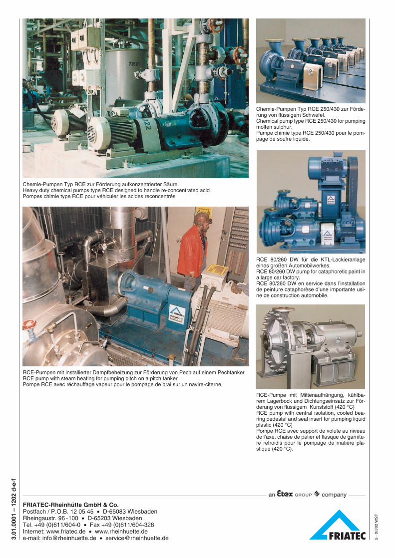
Chemie-Pumpen Typ RCE zur Förderung aufkonzentrierter SäureHeavy duty chemical pumps type RCE designed to handle re-concentrated acidPompes chimie type RCE pour véhiculer les acides reconcentrés
RCE-Pumpen mit installierter Dampfbeheizung zur Förderung von Pech auf einem PechtankerRCE pump with steam heating for pumping pitch on a pitch tankerPompe RCE avec réchauffage vapeur pour le pompage de brai sur un navire-citerne.
Chemie-Pumpen Typ RCE 250/430 zur Förde-rung von flüssigem Schwefel.Chemical pump type RCE 250/430 for pumpingmolten sulphur.Pumpe chimie type RCE 250/430 pour le pom-page de soufre liquide.
RCE 80/260 DW für die KTL-Lackieranlageeines großen Automobilwerkes.RCE 80/260 DW pump for cataphoretic paint ina large car factory.RCE 80/260 DW en service dans l’installationde peinture cataphorèse d’une importante usi-ne de construction automobile.
RCE-Pumpe mit Mittenaufhängung, kühlba-rem Lagerbock und Dichtungseinsatz zur För-derung von flüssigem Kunststoff (420 °C)RCE pump with central isolation, cooled bea-ring pedestal and seal insert for pumping liquidplastic (420 °C)Pompe RCE avec support de volute au niveaude l’axe, chaise de palier et flasque de garnitu-re refroidis pour le pompage de matière pla-stique (420 °C).
3.01
.000
1 –
1202
d-e
-f
5 · X
II/02
WS
T
FRIATEC-Rheinhütte GmbH & Co.Postfach / P.O.B. 12 05 45 • D-65083 WiesbadenRheingaustr. 96 -100 • D-65203 WiesbadenTel. +49 (0)611/604-0 • Fax +49 (0)611/604-328Internet: www.friatec.de • www.rheinhuette.dee-mail: [email protected] • [email protected]