Pool Setup
8
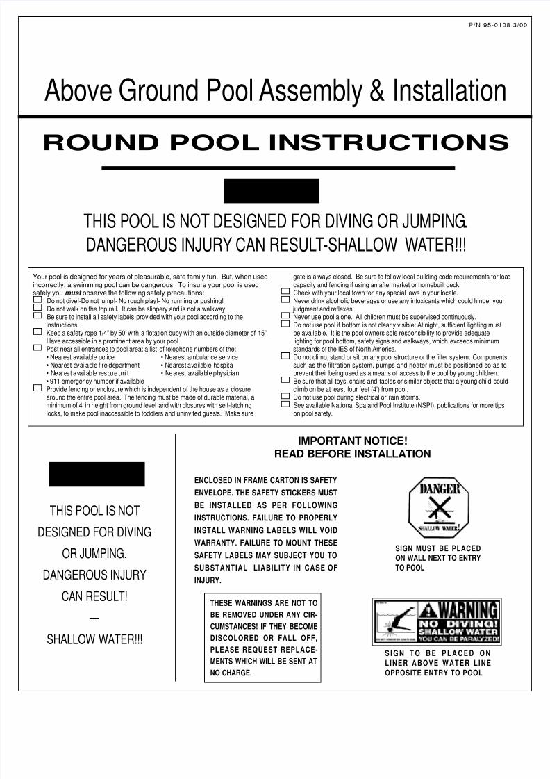
THIS P OOL IS NOT DESIGNED FOR DIVING OR JUMPING. DANGEROUS INJURY CAN RESUL T -SHALLOW WA TER!!! ROUND POOL INSTRUCTIONS WARNING: Your pool is designed for years of pleasurable, safe family fun. But, when used incorrectly, a swimming pool can be dangerous. To insure your pool is used safely you must observe the following safety precautions: Do not dive!-Do not jump!- No rough play!- No running or pushing! Do not walk on the top rail. It can be slippery and is not a walkway. Be sure to install all safety labels provided with your pool according to the instructions. Keep a safety rope 1/4” by 50’ with a flotation buoy with an outside diameter of 15”. Have accessible in a prominent area by your pool. Post near all entrances to pool area; a list of telephone numbers of the: • Nearest available police • Nearest ambulance service • Nearest a va il able fi re de partment • Nearest available hos pi tal • Ne ar es t a va il ab le resc ue un it • Ne ar est a va il ab l e p hys ic ia n • 911 emergency number if available Provide fencing or enclosure which is independent of the house as a closure around the entire pool area. The fencing must be made of durable material, a minimum of 4’ in height from ground level and with closures with self-latching locks, to make pool inaccessible to toddlers and uninvited guest s. Make sure gate is always closed. Be sure to follow local building code requirements for loa d capacity and fencing if using an aftermarket or homebuilt deck. Check with your local town for any special laws in your locale. Never drink alcoholic beverages or use any intoxicants which could hinder your judgment and reflexes. Never use pool alone. All children must be supervised continuous ly. Do not use pool if bottom is not clearly visible: At night, sufficient lighting must be available. It is the pool owners sole responsibility to provide adequate lighting for pool bottom, safety signs and walkways, which exceeds minimum standards of the IES of North America. Do not climb, stand or sit on any pool structure or the filter system. Components such as the filtration system, pumps and heater must be positioned so as to prevent their being used as a means of access to the pool by young children. Be sure that all toys, chairs and tables or similar objects that a young child could climb on be at least four feet (4’) from pool. Do not use pool during electrical or rain storms. See available National Spa and Pool Institute (NSPI), publications for more tips on pool safety. THI S POOL IS NOT DESIGNED FOR DIVING OR JUMPING. DANGEROUS INJURY CAN RESULT! — SHALLOW WATER!!! WARNING: SIGN TO BE PLACED ON LINER ABOVE WATER LINE OPPOSITE ENTRY TO POOL ENCLOSED IN FRAME CARTON IS SAFETY ENVELOPE. THE SAFETY STICKERS MUST BE INSTALLED AS PER FOLLOWING INSTRUCTIONS. FAILURE TO PROPERLY INSTALL WARNING LABELS WILL VOID WARRANTY. FAILURE TO MOUNT THESE SAFETY LABELS MAY SUBJECT YOU TO SUBSTANTIAL LIABILITY IN CASE OF INJURY. IMPORTANT NOTICE! READ BEFORE INSTALLATION SIGN MUST BE PLACED ON WALL NEXT TO ENTRY TO POOL THESE WARNINGS ARE NOT TO BE REMOVED UNDER ANY CIR- CUMSTANCES! IF THEY BECOME DISCOLORED OR FALL OFF, PLEASE REQUEST REPLACE- MENTS WHICH WILL BE SENT AT NO CHARGE. P/N 95-0108 3/00 Above Ground Pool Assembly & Installation
-
Upload
rich-sunyoger -
Category
Documents
-
view
219 -
download
0
Transcript of Pool Setup
8/6/2019 Pool Setup
http://slidepdf.com/reader/full/pool-setup 1/8
THIS POOL IS NOT DESIGNED FOR DIVING OR JUMPING.
DANGEROUS INJURY CAN RESULT-SHALLOW WATER!!!
ROUND POOL INSTRUCTIONS
WARN I NG :
Your pool is designed for years of pleasurable, safe family fun. But, when usedincorrectly, a swimming pool can be dangerous. To insure your pool is usedsafely you must observe the following safety precautions:
Do not dive!-Do not jump!- No rough play!- No running or pushing!Do not walk on the top rail. It can be slippery and is not a walkway.Be sure to install all safety labels provided with your pool according to theinstructions.Keep a safety rope 1/4” by 50’ with a flotation buoy with an outside diameter of 15”.Have accessible in a prominent area by your pool.Post near all entrances to pool area; a list of telephone numbers of the:• Nearest available police • Nearest ambulance service• Nearest available fire department • Nearest available hospital• Nearest available rescue unit • Nearest avai lable physician• 911 emergency number if availableProvide fencing or enclosure which is independent of the house as a closurearound the entire pool area. The fencing must be made of durable material, aminimum of 4’ in height from ground level and with closures with self-latchinglocks, to make pool inaccessible to toddlers and uninvited guests. Make sure
gate is always closed. Be sure to follow local building code requirements for loadcapacity and fencing if using an aftermarket or homebuilt deck.Check with your local town for any special laws in your locale.Never drink alcoholic beverages or use any intoxicants which could hinder your judgment and reflexes.Never use pool alone. All children must be supervised continuously.Do not use pool if bottom is not clearly visible: At night, sufficient lighting mustbe available. It is the pool owners sole responsibility to provide adequatelighting for pool bottom, safety signs and walkways, which exceeds minimumstandards of the IES of North America.Do not climb, stand or sit on any pool structure or the filter system. Componentssuch as the filtration system, pumps and heater must be positioned so as toprevent their being used as a means of access to the pool by young children.Be sure that all toys, chairs and tables or similar objects that a young child couldclimb on be at least four feet (4’) from pool.Do not use pool during electrical or rain storms.See available National Spa and Pool Institute (NSPI), publications for more tipson pool safety.
THIS POOL IS NOT
DESIGNED FOR DIVING
OR JUMPING.
DANGEROUS INJURY
CAN RESULT!
—
SHALLOW WATER!!!
WARN I NG :
S I G N T O B E P L A C E D O N
LINER ABOVE WATER LINE
OPPOSITE ENTRY TO POOL
ENCLOSED IN FRAME CARTON IS SAFETY
ENVELOPE. THE SAFETY STICKERS MUST
BE INSTALLED AS PER FOLLOWING
INSTRUCTIONS. FAILURE TO PROPERLY
INSTALL WARNING LABELS WILL VOID
WARRANTY. FAILURE TO MOUNT THESESAFETY LABELS MAY SUBJECT YOU TO
SUBSTANTIAL LIABILITY IN CASE OF
INJURY.
IMPORTANT NOTICE!READ BEFORE INSTALLATION
SIGN MUST BE PLACEDON WALL NEXT TO ENTRY
TO POOL
THESE WARNINGS ARE NOT TO
BE REMOVED UNDER ANY CIR-
CUMSTANCES! IF THEY BECOME
DISCOLORED OR FALL OFF,
PLEASE REQUEST REPLACE-
MENTS WHICH WILL BE SENT AT
NO CHARGE.
P/N 95-0108 3
Above Ground Pool Assembly & Installation
8/6/2019 Pool Setup
http://slidepdf.com/reader/full/pool-setup 2/8
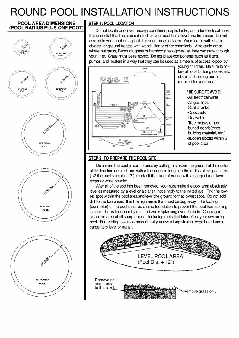
POOL AREA DIMENSIONS(POOL RADIUS PLUS ONE FOOT)
STEP 1: POOL LOCATION
1 5 ’ R
a d i u
s
28’ ROUND
POOL
1 7 ’ R
a d i u
s
33’ ROUND
POOL
1 3 ’ R
a d i u
s
24’ ROUND
POOL
1 0 ’ R
a d i u
s
18’ ROUNDPOOL
Do not locate pool over underground lines, septic tanks, or under electrical linIt is essential that the area selected for your pool has a level and firm base. Do nassemble your pool on asphalt, tar or oil base surfaces. Avoid areas with sharp
objects, or ground treated with weed killer or other chemicals. Also avoid areaswhere nut grass, Bermuda grass or bamboo grass grows, as they can grow throyour liner. Grass must be removed. Do not place components such as filters,
pumps, and heaters in a way that they can be used as a means of access to poolyoung children. Be sure to low all local building codes obtain all building permits
required for your area.
*BE SURE TO AVOID:
-All electrical wires
-All gas lines-Septic tanks-Cesspools
-Dry wells-Tree roots/stumps-buried debris(trees,building material, etc
-sudden slopes withinof pool area
Remove soiland grassto this level.
Remove grass only.
Determine the pool circumference by putting a stake in the ground at the cen
of the location desired, and with a line equal in length to the radius of the pool a
(1/2 the pool size plus 12”), mark off the circumference with a sharp object, lawnedger or white powder.After all of the sod has been removed, you must make the pool area absolute
level as measured by a level or a transit, not simply to the naked eye. Find the loest spot within the pool area and level the ground to that lowest spot. Do not addirt to the low areas. It is the high areas that must be dug away. The footing
(perimeter) of the pool must be a solid foundation to prevent the pool from settliinto dirt that is loosened by rain and water splashing over the side. Once again,clean the area of all sharp objects, including roots that later effect your swimminpool. For leveling, we recommend that you use a long straight edge board and a
carpenters level or transit.
ROUND POOL INSTALLATION INSTRUCTION
STEP 2: TO PREPARE THE POOL SITE
LEVEL POOL AREA(Pool Dia. + 12”)
1 1 ’ R
a d i u
s
20’ ROUNDPOOL
7 ’
R a d i u
s
12’ ROUNDPOOL
8 ’ 6 ”
R a d i u
s
15’ ROUNDPOOL
8/6/2019 Pool Setup
http://slidepdf.com/reader/full/pool-setup 3/8
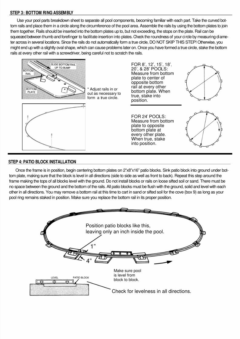
Use your pool parts breakdown sheet to separate all pool components, becoming familiar with each part. Take the curved bo
tom rails and place them in a circle along the circumference of the pool area. Assemble the rails by using the bottom plates to jo
them together. Rails should be inserted into the bottom plates up to, but not exceeding, the stops on the plate. Rail can be
squeezed between thumb and forefinger to facilitate insertion into plates. Check the roundness of your circle by measuring diam
ter across in several locations. Since the rails do not automatically form a true circle, DO NOT SKIP THIS STEP! Otherwise, you
might end up with a slightly oval shape, which can cause problems later on. Once you have formed a true circle, stake the botto
rails at every other rail with a screwdriver, being careful not to scratch the rails.
FOR 24’ POOLS:Measure from bottomplate to oppositebottom plate atevery other plate.When true, stakeinto position.
FOR 8’, 12’, 15’, 18’,20’, & 28’ POOLS:Measure from bottomplate to center ofopposite bottomrail at every otherbottom plate. Whentrue, stake intoposition.
* Adjust rails in orout as necessary toform a true circle.
Check for levelness in all directions.
Position patio blocks like this,
leaving only an inch inside the pool.
Make sure poolis level fromblock to block.
1”
4”
STEP 3: BOTTOM RING ASSEMBLY
STEP 4: PATIO BLOCK INSTALLATION
Once the frame is in position, begin centering bottom plates on 2”x8”x16” patio blocks. Sink patio block into ground under b
tom plate, making sure that the block is level in all directions (side to side as well as front to back). Repeat this step around the
frame making the tops of all blocks level with the ground. Do not install blocks or rails on loose sifted soil or sand. There must b
no space between the ground and the bottom of the rails. All patio blocks must be flush with the ground, solid and level with eac
other in all directions. You may remove a bottom rail at this time to cart in sand or sifted soil for the cove (box 9) as long as your
pool ring remains staked in position. Make sure you replace the bottom rail in its proper position.
8/6/2019 Pool Setup
http://slidepdf.com/reader/full/pool-setup 4/8
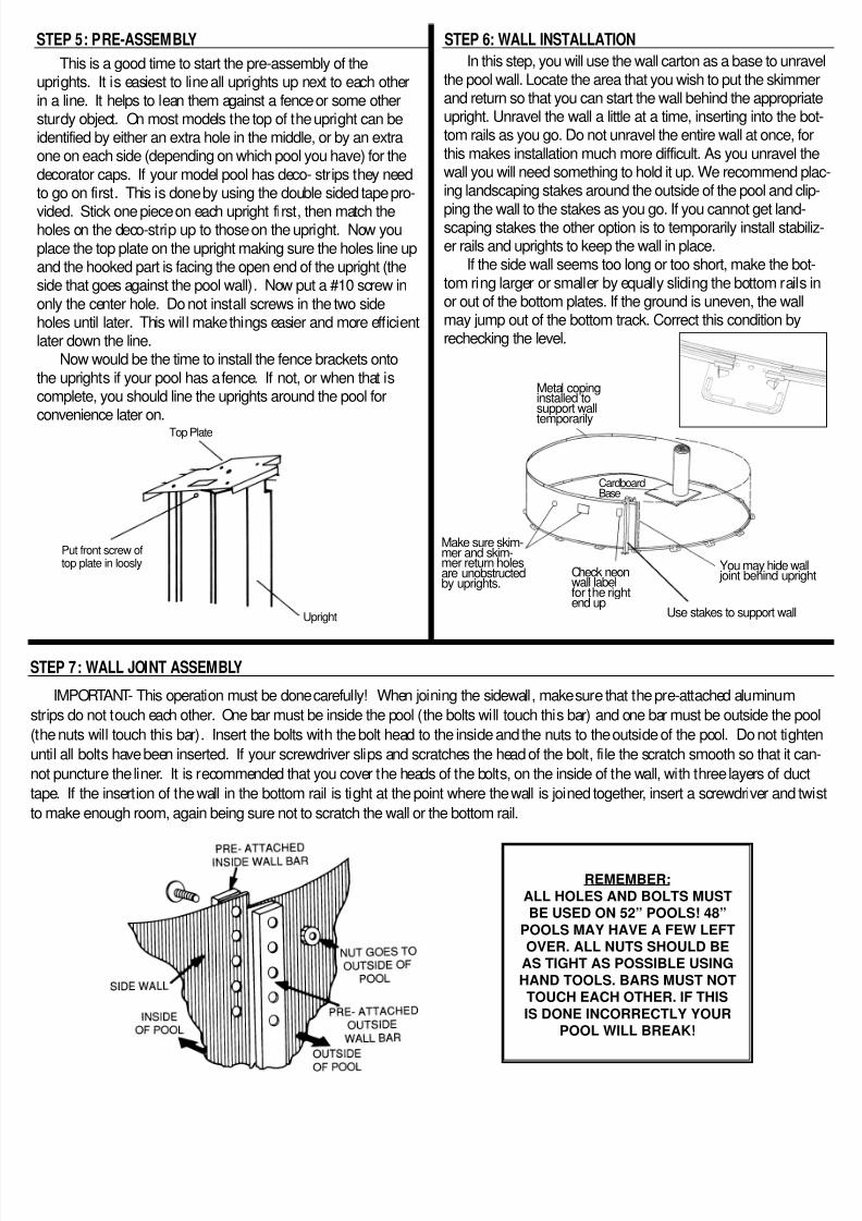
STEP 5: PRE-ASSEMBLY
In this step, you will use the wall carton as a base to unra
the pool wall. Locate the area that you wish to put the skimmand return so that you can start the wall behind the appropriupright. Unravel the wall a little at a time, inserting into the btom rails as you go. Do not unravel the entire wall at once, fo
this makes installation much more difficult. As you unravel twall you will need something to hold it up. We recommend ping landscaping stakes around the outside of the pool and cl
ping the wall to the stakes as you go. If you cannot get land-scaping stakes the other option is to temporarily install staber rails and uprights to keep the wall in place.
If the side wall seems too long or too short, make the bo
tom ring larger or smaller by equally sliding the bottom railsor out of the bottom plates. If the ground is uneven, the wallmay jump out of the bottom track. Correct this condition byrechecking the level.
Top Plate
IMPORTANT- This operation must be done carefully! When joining the sidewall, make sure that the pre-attached aluminum
strips do not touch each other. One bar must be inside the pool (the bolts will touch this bar) and one bar must be outside the p
the nuts will touch this bar). Insert the bolts with the bolt head to the inside and the nuts to the outside of the pool. Do not tigh
until all bolts have been inserted. If your screwdriver slips and scratches the head of the bolt, file the scratch smooth so that it c
not puncture the liner. It is recommended that you cover the heads of the bolts, on the inside of the wall, with three layers of duc
ape. If the insertion of the wall in the bottom rail is tight at the point where the wall is joined together, insert a screwdriver and t
o make enough room, again being sure not to scratch the wall or the bottom rail.
STEP 6: WALL INSTALLATION
Upright
Put front screw oftop plate in loosly
STEP 7: WALL JOINT ASSEMBLY
REMEMBER:
ALL HOLES AND BOLTS MUSTBE USED ON 52” POOLS! 48”
POOLS MAY HAVE A FEW LEFTOVER. ALL NUTS SHOULD BE
AS TIGHT AS POSSIBLE USING
HAND TOOLS. BARS MUST NOTTOUCH EACH OTHER. IF THIS
IS DONE INCORRECTLY YOURPOOL WILL BREAK!
This is a good time to start the pre-assembly of theuprights. It is easiest to line all uprights up next to each other
in a line. It helps to lean them against a fence or some othersturdy object. On most models the top of the upright can beidentified by either an extra hole in the middle, or by an extraone on each side (depending on which pool you have) for the
decorator caps. If your model pool has deco- strips they needto go on first. This is done by using the double sided tape pro-
vided. Stick one piece on each upright first, then match theholes on the deco-strip up to those on the upright. Now you
place the top plate on the upright making sure the holes line upand the hooked part is facing the open end of the upright (theside that goes against the pool wall). Now put a #10 screw in
only the center hole. Do not install screws in the two sideholes until later. This will make things easier and more efficientlater down the line.
Now would be the time to install the fence brackets onto
the uprights if your pool has a fence. If not, or when that iscomplete, you should line the uprights around the pool forconvenience later on.
Metal copinginstalled tosupport walltemporarily
CardboardBase
You may hide wa joint behind uprig
Use stakes to support wall
Check neonwall labelfor the rightend up
Make sure skim-mer and skim-mer return holesare unobstructedby uprights.
8/6/2019 Pool Setup
http://slidepdf.com/reader/full/pool-setup 5/8
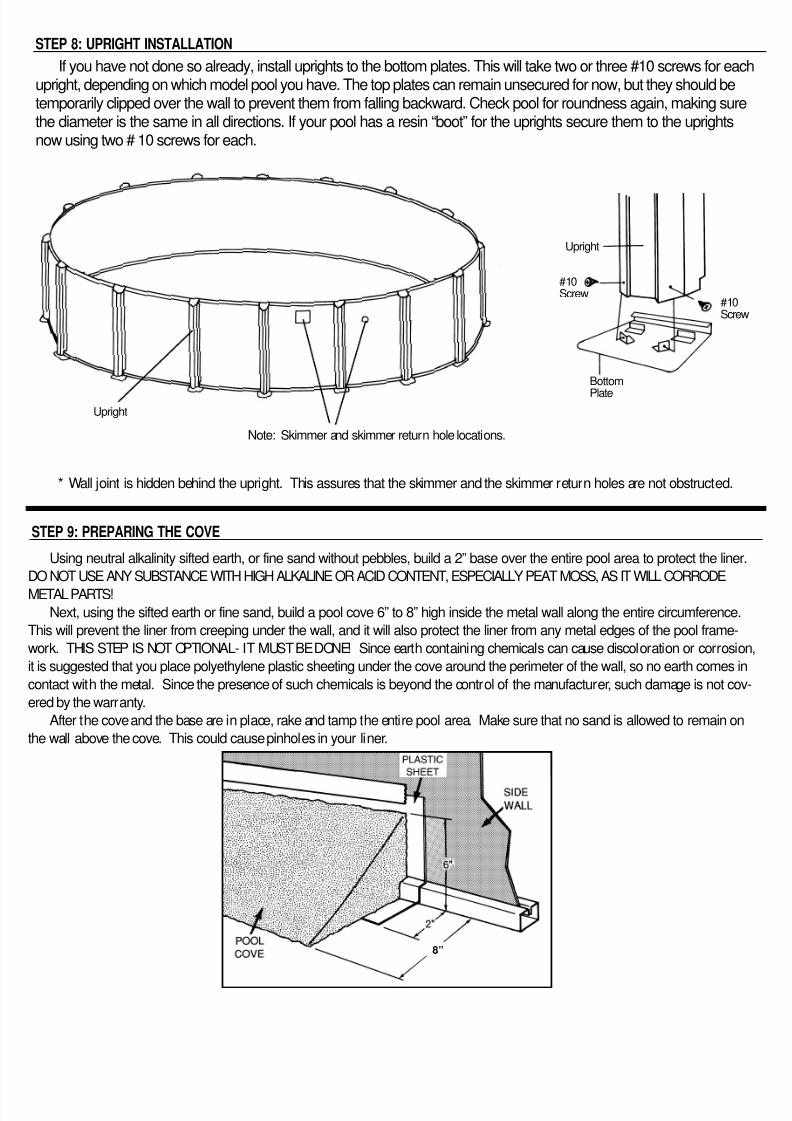
If you have not done so already, install uprights to the bottom plates. This will take two or three #10 screws for eaupright, depending on which model pool you have. The top plates can remain unsecured for now, but they should betemporarily clipped over the wall to prevent them from falling backward. Check pool for roundness again, making suthe diameter is the same in all directions. If your pool has a resin “boot” for the uprights secure them to the uprightsnow using two # 10 screws for each.
* Wall joint is hidden behind the upright. This assures that the skimmer and the skimmer return holes are not obstructed.
STEP 8: UPRIGHT INSTALLATION
Upright
Note: Skimmer and skimmer return hole locations.
Upright
#10Screw
Bottom
Plate
#10Scre
Using neutral alkalinity sifted earth, or fine sand without pebbles, build a 2” base over the entire pool area to protect the line
DO NOT USE ANY SUBSTANCE WITH HIGH ALKALINE OR ACID CONTENT, ESPECIALLY PEAT MOSS, AS IT WILL CORRODE
METAL PARTS!
Next, using the sifted earth or fine sand, build a pool cove 6” to 8” high inside the metal wall along the entire circumference
This will prevent the liner from creeping under the wall, and it will also protect the liner from any metal edges of the pool frame-
work. THIS STEP IS NOT OPTIONAL- IT MUST BE DONE! Since earth containing chemicals can cause discoloration or corrosi
t is suggested that you place polyethylene plastic sheeting under the cove around the perimeter of the wall, so no earth comes
contact with the metal. Since the presence of such chemicals is beyond the control of the manufacturer, such damage is not co
ered by the warranty.
After the cove and the base are in place, rake and tamp the entire pool area. Make sure that no sand is allowed to remain o
he wall above the cove. This could cause pinholes in your liner.
STEP 9: PREPARING THE COVE
8”
8/6/2019 Pool Setup
http://slidepdf.com/reader/full/pool-setup 6/8
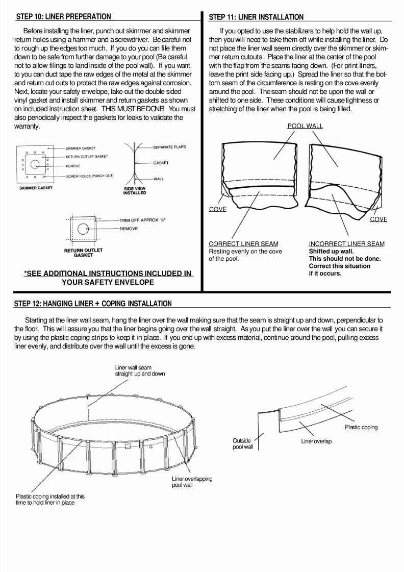
STEP 10: LINER PREPERATION
Before installing the liner, punch out skimmer and skimmer
eturn holes using a hammer and a screwdriver. Be careful noto rough up the edges too much. If you do you can file themdown to be safe from further damage to your pool (Be carefulnot to allow filings to land inside of the pool wall). If you want
o you can duct tape the raw edges of the metal at the skimmerand return cut outs to protect the raw edges against corrosion.Next, locate your safety envelope, take out the double sided
vinyl gasket and install skimmer and return gaskets as shownon included instruction sheet. THIS MUST BE DONE! You mustalso periodically inspect the gaskets for leaks to validate thewarranty.
*SEE ADDITIONAL INSTRUCTIONS INCLUDED IN
YOUR SAFETY ENVELOPE
If you opted to use the stabilizers to help hold the wall uthen you will need to take them off while installing the liner. not place the liner wall seem directly over the skimmer or skmer return cutouts. Place the liner at the center of the pool
with the flap from the seams facing down. (For print liners,leave the print side facing up.) Spread the liner so that the btom seam of the circumference is resting on the cove evenly
around the pool. The seam should not be upon the wall or
shifted to one side. These conditions will cause tightness ostretching of the liner when the pool is being filled.
CORRECT LINER SEAMResting evenly on the coveof the pool.
INCORRECT LINER SEAShifted up wall.This should not be doneCorrect this situationif it occurs.
POOL WALL
COVE
CO
STEP 11: LINER INSTALLATION
STEP 12: HANGING LINER + COPING INSTALLATION
Starting at the liner wall seam, hang the liner over the wall making sure that the seam is straight up and down, perpendicularhe floor. This will assure you that the liner begins going over the wall straight. As you put the liner over the wall you can secure
by using the plastic coping strips to keep it in place. If you end up with excess material, continue around the pool, pulling excesner evenly, and distribute over the wall until the excess is gone.
Liner wall seamstraight up and down
Outsidepool wall
Liner overlap
Plastic coping
Liner overlappingpool wall
Plastic coping installed at this
time to hold liner in place
8/6/2019 Pool Setup
http://slidepdf.com/reader/full/pool-setup 7/8
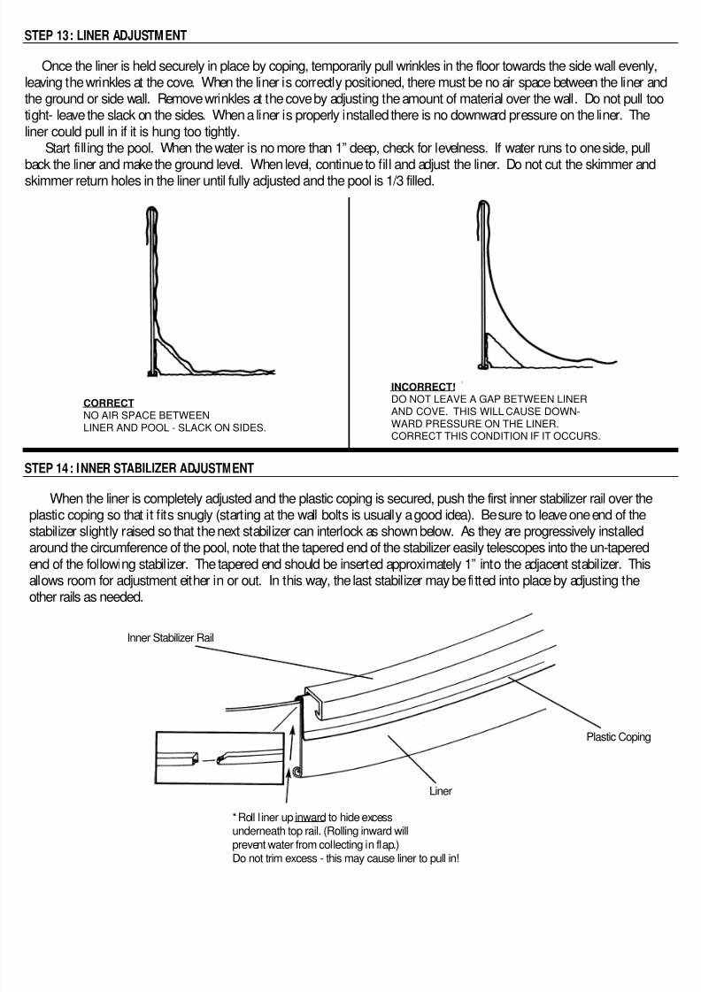
Once the liner is held securely in place by coping, temporarily pull wrinkles in the floor towards the side wall evenlyeaving the wrinkles at the cove. When the liner is correctly positioned, there must be no air space between the liner ahe ground or side wall. Remove wrinkles at the cove by adjusting the amount of material over the wall. Do not pull tight- leave the slack on the sides. When a liner is properly installed there is no downward pressure on the liner. Thener could pull in if it is hung too tightly.
Start filling the pool. When the water is no more than 1” deep, check for levelness. If water runs to one side, pullback the liner and make the ground level. When level, continue to fill and adjust the liner. Do not cut the skimmer andskimmer return holes in the liner until fully adjusted and the pool is 1/3 filled.
INCORRECT!DO NOT LEAVE A GAP BETWEEN LINER
AND COVE. THIS WILL CAUSE DOWN-
WARD PRESSURE ON THE LINER.CORRECT THIS CONDITION IF IT OCCURS.
CORRECTNO AIR SPACE BETWEEN
LINER AND POOL - SLACK ON SIDES.
STEP 13: LINER ADJUSTM ENT
STEP 14: INNER STABILIZER ADJUSTMENT
When the liner is completely adjusted and the plastic coping is secured, push the first inner stabilizer rail over the
plastic coping so that it fits snugly (starting at the wall bolts is usually a good idea). Be sure to leave one end of thestabilizer slightly raised so that the next stabilizer can interlock as shown below. As they are progressively installedaround the circumference of the pool, note that the tapered end of the stabilizer easily telescopes into the un-taperedend of the following stabilizer. The tapered end should be inserted approximately 1” into the adjacent stabilizer. Thisallows room for adjustment either in or out. In this way, the last stabilizer may be fitted into place by adjusting theother rails as needed.
*Roll liner up inward to hide excessunderneath top rail. (Rolling inward will
prevent water from collecting in flap.)Do not trim excess - this may cause liner to pull in!
Plastic Coping
Inner Stabilizer Rail
Liner
8/6/2019 Pool Setup
http://slidepdf.com/reader/full/pool-setup 8/8
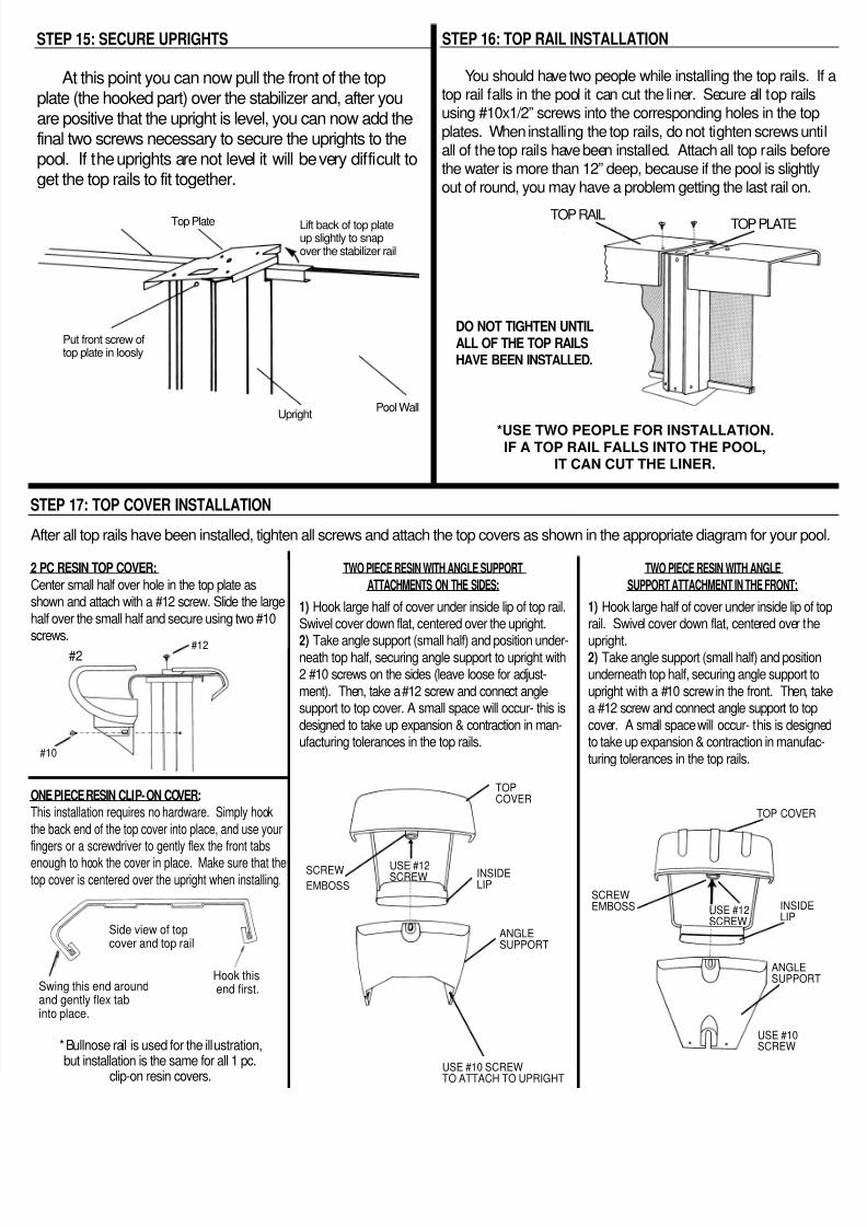
STEP 15: SECURE UPRIGHTS STEP 16: TOP RAIL INSTALLATION
At this point you can now pull the front of the topplate (the hooked part) over the stabilizer and, after youare positive that the upright is level, you can now add thefinal two screws necessary to secure the uprights to thepool. If the uprights are not level it will be very difficult toget the top rails to fit together.
Top Plate
UprightPool Wall
Lift back of top plateup slightly to snapover the stabilizer rail
Put front screw oftop plate in loosly
You should have two people while installing the top rails.top rail falls in the pool it can cut the liner. Secure all top railusing #10x1/2” screws into the corresponding holes in the to
plates. When installing the top rails, do not tighten screws uall of the top rails have been installed. Attach all top rails befthe water is more than 12” deep, because if the pool is slightout of round, you may have a problem getting the last rail on
DO NOT TIGHTEN UNTIL
ALL OF THE TOP RAILS
HAVE BEEN INSTALLED.
*USE TWO PEOPLE FOR INSTALLATION.IF A TOP RAIL FALLS INTO THE POOL,
IT CAN CUT THE LINER.
TOP RAIL TOP PLATE
PC RESIN TOP COVER:
Center small half over hole in the top plate ashown and attach with a #12 screw. Slide the large
half over the small half and secure using two #10crews.
After all top rails have been installed, tighten all screws and attach the top covers as shown in the appropriate diagram for your p
ONE PIECE RESIN CLIP-ON COVER:
This installation requires no hardware. Simply hook
he back end of the top cover into place, and use yourngers or a screwdriver to gently flex the front tabs
nough to hook the cover in place. Make sure that theop cover is centered over the upright when installing.
TWO PIECE RESIN WITH ANGLE SUPPORT
ATTACHMENTS ON THE SIDES:
1) Hook large half of cover under inside lip of top rail.Swivel cover down flat, centered over the upright.
2) Take angle support (small half) and position under-neath top half, securing angle support to upright with2 #10 screws on the sides (leave loose for adjust-
ment). Then, take a #12 screw and connect anglesupport to top cover. A small space will occur- this is
designed to take up expansion & contraction in man-ufacturing tolerances in the top rails.
TWO PIECE RESIN WITH ANGLE
SUPPORT ATTACHMENT IN THE FRONT:
1) Hook large half of cover under inside lip orail. Swivel cover down flat, centered over th
upright.2) Take angle support (small half) and positiounderneath top half, securing angle support t
upright with a #10 screw in the front. Then, a #12 screw and connect angle support to to
cover. A small space will occur- this is desigto take up expansion & contraction in manufa
turing tolerances in the top rails.
Side view of topcover and top rail
Swing this end aroundand gently flex tabinto place.
*Bullnose rail is used for the illustration,but installation is the same for all 1 pc.
clip-on resin covers.
Hook thisend first.
TOPCOVER
SCREW
EMBOSSINSIDELIP
ANGLESUPPORT
USE #12SCREW
#12
USE #10 SCREWTO ATTACH TO UPRIGHT
USE #10SCREW
INSIDELIP
TOP COVER
ANGLESUPPOR
SCREWEMBOSS USE #12
SCREW
STEP 17: TOP COVER INSTALLATION
#10
#2