Portable Insulation Fault Location System ... - Bender … · EDS3365 and EDS3360 Portable...
43
EDS3365 and EDS3360 Portable Insulation Fault Location System for IT AC and DC Systems and Residual Current Measurements in earthed Systems Operating Manual TGH1320E BENDER
-
Upload
vuongtuyen -
Category
Documents
-
view
229 -
download
0
Transcript of Portable Insulation Fault Location System ... - Bender … · EDS3365 and EDS3360 Portable...
EDS3365 and EDS3360
Portable Insulation FaultLocation System forIT AC and DC Systems andResidual Current Measurementsin earthed Systems
Operating Manual TGH1320E
BEN
DER

© 2000 BENDER, Germany Alle Rechte vorbehaltenNachdruck nur mit Genehmigung des HerausgebersÄnderungen vorbehalten
Dipl.Ing. W. Bender GmbH & Co KGLondorfer Str. 65 • 35305 Grünberg
Postfach 1161 • 35301 GrünbergTel.: +49 - 6401 - 807 - 0Fax: +49 - 6401 - 807259
E-Mail: [email protected]: http://www.bender-de.com

3TGH1320E/03.2000
Contents
1 About the EDS3365 ........................................................................... 4Critical use ....................................................................................... 4The insulation resistance ................................................................ 5Basic standards ................................................................................ 6Terms and definitions ..................................................................... 6Proper use ....................................................................................... 7Warranty and liability ...................................................................... 7Personnel ......................................................................................... 7
2 Safety instructions ............................................................................. 7Risks when operating the system................................................... 7
3 Operating principle of the EDS3365 .............................................. 10Operating principle insulation fault location (EDS-mode) ......... 10Response values ............................................................................ 11Terminology .................................................................................. 11FAULT curve .................................................................................. 12Function in the RCM mode .......................................................... 13Direction of energy ....................................................................... 14
4 Product description ......................................................................... 15The system components at a glance ............................................ 15Options .......................................................................................... 16Aluminium case ............................................................................. 17EDS165-3 insulation fault evaluator ............................................. 17Test device PGH183 ...................................................................... 18PSA3320 current clamp ................................................................. 19PSA3352 current clamp ................................................................. 19Technical data ............................................................................... 20Factory settings ............................................................................. 22
5 Operation and Setting..................................................................... 22Settings on the EDS165-3 evaluator ............................................. 22The EDS165-3 display ................................................................... 235 menus ......................................................................................... 23The EDS165-3 in the EDS mode .................................................. 24The EDS165-3 in the RCM mode.................................................. 26Serial interface ............................................................................... 28Interface protocol .......................................................................... 28Replacing the accumulators .......................................................... 29
6 Points to be considered before use ............................................... 30Reduced measuring current .......................................................... 30A sensible approach to fault location .......................................... 31Characteristic curves ..................................................................... 32Limits of insulation fault location ................................................. 34
7 Practical use .................................................................................... 35Use as a portable insulation fault location system ...................... 35Using the EDS165-3 within an EDS470 system ........................... 37Using the EDS165-3 as a residual current monitor ..................... 39Insulation fault location with the EDS3365in diode-decoupled systems ......................................................... 40Sequence of the insulation fault location .................................... 42
8 Ordering information ...................................................................... 43
4TGH1320E/03.2000
1 About the EDS3365
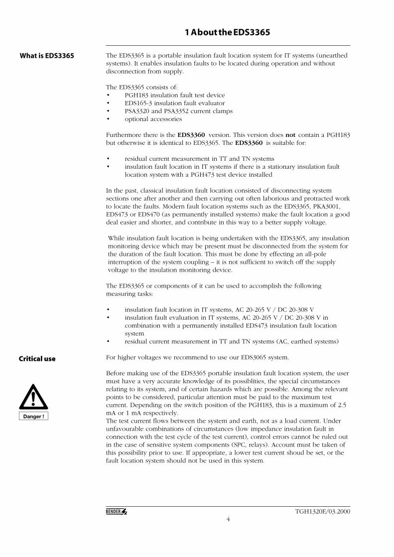
What is EDS3365 The EDS3365 is a portable insulation fault location system for IT systems (unearthedsystems). It enables insulation faults to be located during operation and withoutdisconnection from supply.
The EDS3365 consists of:• PGH183 insulation fault test device• EDS165-3 insulation fault evaluator• PSA3320 and PSA3352 current clamps• optional accessories
Furthermore there is the EDS3360 version. This version does not contain a PGH183but otherwise it is identical to EDS3365. The EDS3360 is suitable for:
• residual current measurement in TT and TN systems• insulation fault location in IT systems if there is a stationary insulation fault
location system with a PGH473 test device installed
In the past, classical insulation fault location consisted of disconnecting systemsections one after another and then carrying out often laborious and protracted workto locate the faults. Modern fault location systems such as the EDS3365, PKA3001,EDS473 or EDS470 (as permanently installed systems) make the fault location a gooddeal easier and shorter, and contribute in this way to a better supply voltage.
While insulation fault location is being undertaken with the EDS3365, any insulationmonitoring device which may be present must be disconnected from the system forthe duration of the fault location. This must be done by effecting an all-poleinterruption of the system coupling – it is not sufficient to switch off the supplyvoltage to the insulation monitoring device.
The EDS3365 or components of it can be used to accomplish the followingmeasuring tasks:
• insulation fault location in IT systems, AC 20-265 V / DC 20-308 V• insulation fault evaluation in IT systems, AC 20-265 V / DC 20-308 V in
combination with a permanently installed EDS473 insulation fault locationsystem
• residual current measurement in TT and TN systems (AC, earthed systems)
For higher voltages we recommend to use our EDS3065 system.
Before making use of the EDS3365 portable insulation fault location system, the usermust have a very accurate knowledge of its possiblities, the special circumstancesrelating to its system, and of certain hazards which are possible. Among the relevantpoints to be considered, particular attention must be paid to the maximum testcurrent. Depending on the switch position of the PGH183, this is a maximum of 2.5mA or 1 mA respectively.The test current flows between the system and earth, not as a load current. Underunfavourable combinations of circumstances (low impedance insulation fault inconnection with the test cycle of the test current), control errors cannot be ruled outin the case of sensitive system components (SPC, relays). Account must be taken ofthis possibility prior to use. If appropriate, a lower test current shoud be set, or thefault location system should not be used in this system.
Critical use
Danger !
5TGH1320E/03.2000
About EDS3365
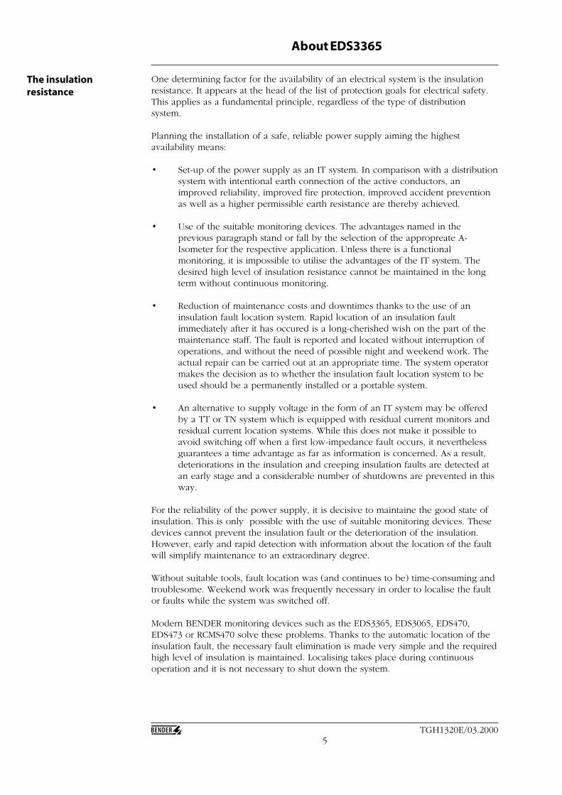
One determining factor for the availability of an electrical system is the insulationresistance. It appears at the head of the list of protection goals for electrical safety.This applies as a fundamental principle, regardless of the type of distributionsystem.
Planning the installation of a safe, reliable power supply aiming the highestavailability means:
• Set-up of the power supply as an IT system. In comparison with a distributionsystem with intentional earth connection of the active conductors, animproved reliability, improved fire protection, improved accident preventionas well as a higher permissible earth resistance are thereby achieved.
• Use of the suitable monitoring devices. The advantages named in theprevious paragraph stand or fall by the selection of the appropreate A-Isometer for the respective application. Unless there is a functionalmonitoring, it is impossible to utilise the advantages of the IT system. Thedesired high level of insulation resistance cannot be maintained in the longterm without continuous monitoring.
• Reduction of maintenance costs and downtimes thanks to the use of aninsulation fault location system. Rapid location of an insulation faultimmediately after it has occured is a long-cherished wish on the part of themaintenance staff. The fault is reported and located without interruption ofoperations, and without the need of possible night and weekend work. Theactual repair can be carried out at an appropriate time. The system operatormakes the decision as to whether the insulation fault location system to beused should be a permanently installed or a portable system.
• An alternative to supply voltage in the form of an IT system may be offeredby a TT or TN system which is equipped with residual current monitors andresidual current location systems. While this does not make it possible toavoid switching off when a first low-impedance fault occurs, it neverthelessguarantees a time advantage as far as information is concerned. As a result,deteriorations in the insulation and creeping insulation faults are detected atan early stage and a considerable number of shutdowns are prevented in thisway.
For the reliability of the power supply, it is decisive to maintaine the good state ofinsulation. This is only possible with the use of suitable monitoring devices. Thesedevices cannot prevent the insulation fault or the deterioration of the insulation.However, early and rapid detection with information about the location of the faultwill simplify maintenance to an extraordinary degree.
Without suitable tools, fault location was (and continues to be) time-consuming andtroublesome. Weekend work was frequently necessary in order to localise the faultor faults while the system was switched off.
Modern BENDER monitoring devices such as the EDS3365, EDS3065, EDS470,EDS473 or RCMS470 solve these problems. Thanks to the automatic location of theinsulation fault, the necessary fault elimination is made very simple and the requiredhigh level of insulation is maintained. Localising takes place during continuousoperation and it is not necessary to shut down the system.
The insulationresistance
6TGH1320E/03.2000
About EDS3365
If a power supply system is set-up as an IT system, the relevant standards requirethat the first insulation fault to occur must be eliminated as quickly as possible:
IEC 60364-4-41, Point 413.1.5.4 (Note),DIN VDE 0100 Part 410:1997-01, Point 413.1.5.4 (Note)
It is recommended that the first fault should be eliminated with the shortestpractical delay.
Rapid insulation fault location is made possible thanks to insulation fault locatingsystems such as the EDS3365, EDS3065, EDS473, EDS470 or RCMS470. In this way,the risk of the supply voltage being switched off because of a possible secondfault is considerably reduced.
The standard IEC61557-9 deals with devices for insulation fault location in IT ACsystems during operation, IT AC systems with galvanically connected DC circuitsand IT DC systems. This international standard lays down some specialrequirements for insulation fault location systems in IT systems of up to AC 1000V and DC 1500 V.
BENDER‘s insulation fault location systems are based on this standard IEC61557-9.As far as possible, this operating manual attempts to use the terminology of thedraft standard, including the term ‘insulation fault location system´. This indicatesnot only that insulation faults with 0 Ω (earth faults) are found, but also resistivefaults.
In addition, IEC 61010-1 is applicable. The title of this international standard is”Safety requirements for electrical equipment for measurement, controland laboratory use”.
I∆ = fault current. The current that comes to flow through an insulation fault.I∆n
= rated residual operating current. The fault current at which the evaluator unit responds under specified conditions.
I∆s= measured value of the selective fault current of the evaluator unit.
IMD = Insulation Monitoring DeviceRCM = Residual Current MonitorRCD = Residual Current Protective Device
Basic standards
Terms and definitions
7TGH1320E/03.2000
2 Safety instructions
The intended use of the EDS3365 is to:• locate insulation faults in IT systems, AC 50, 60 and 400 Hz, 20-265V and DC
20-308 V.In addition to this, the EDS165-3 insulation fault evaluator – which is a componentof the EDS3365 – can be used to:• evaluate insulation faults in combination with a permanently installed EDS473
insulation fault location system (EDS mode)• measure residual currents in TN and TT systems (RCM mode)Any other use, or any use which goes beyond the foregoing, is deemed to beimproper. The BENDER companies shall not be liable for any loss and damagesarising therefrom.
As a basic principle our ”General Conditions of Sale and Delivery” shall apply.These shall be available to the operator no earlier than the time when the contract isconcluded.
Warranty and liability claims in the event of injury to persons or damage to propertyare excluded if they can be attributed to one or more of the following causes:
• Inproper use of the EDS3365.• Improper assembly/fitting, commissioning, operation and maintenance of the
EDS3365.• Failure to take note of the information in the operating instructions
concerning transport, storage, assembly/fitting, commissioning, operation andmaintenance of the EDS3365.
• Unauthorised structural modifications to the EDS3365.• Failure to take note of the technical data.• Improperly performed repairs and the use of spare parts or accessories which
are not recommended by the manufacturer• Cases of disaster brought about by the effect of foreign bodies and force
majeure• The assembly and installation of non-recommended combinations of devices.
In order to handle the EDS3365 in accordance with safety requirements and toensure ist trouble-free operation, the fundamental prerequisite is a knowledge of thebasic safety information and the safety regulations.
Everyone who works with the EDS3365 must take note of this operating manual,and in particular of the safety information.In addition to this, the rules and regulations concerning accident prevention whichare valid for the operating location must be obeyed.
Only suitably qualified staff may work with the EDS3365. The term ‘qualified´ meansthat such staff are familiar with the assembly, commissioning and operation of theproduct and that they have undergone training which is appropriate to theiractivities.The staff must have read and understood the safety chapter and the warnings inthese operating instructions.
The EDS3365 is built according to the state-of-the-art and the recognised safetyengineering rules. During use, it is nevertheless possible that dangers will arise tothe life and limb of the user or of third parties, or that the EDS3365 system or otheritems of property may be impaired. The EDS3365 must only be used:
• for the purposes for which it is intended• when it is in perfect condition as regards safety engineering aspects
Intended use
Warranty and liability
Personnel
Risks when operatingthe system
8TGH1320E/03.2000
Safety instructions
Any faults which might impair safety must be eliminated immediately. Inadmissablemodifications, and the use of spare parts and additional devices which are not soldor recommended by the manufacturer of the devices may cause fires, electric shocksand injuries.
Explanation of symbolsand notes
The following designations and symbols for hazards and warnings are used inBENDER documentation:
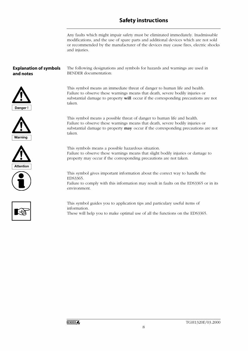
This symbol means an immediate threat of danger to human life and health.Failure to observe these warnings means that death, severe bodily injuries orsubstantial damage to property will occur if the corresponding precautions are nottaken.
This symbol means a possible threat of danger to human life and health.Failure to observe these warnings means that death, severe bodily injuries orsubstantial damage to property may occur if the corresponding precautions are nottaken.
This symbols means a possible hazardous situation.Failure to observe these warnings means that slight bodily injuries or damage toproperty may occur if the corresponding precautions are not taken.
This symbol gives important information about the correct way to handle theEDS3365.Failure to comply with this information may result in faults on the EDS3365 or in itsenvironment.
This symbol guides you to application tips and particulary useful items ofinformation.These will help you to make optimal use of all the functions on the EDS3365.
Danger !
Warning
Attention
9TGH1320E/03.2000
Safety instructions
Inspect the despatch and equipment packaging for damage, and compare thecontents of the package with the delivery documents. In the event of transportdamage, please notify the BENDER company immediately.The components of the EDS3365 must only be stored in rooms where they will beprotected against dust, moisture, and sprayed or dripping water, and where theindicated storage temperatures are maintained.
BENDER provides a warranty for fault-free execution and faultless material qualityon the EDS3365 with all its components for a period of 12 months as from the dateof delivery, under normal operating conditions.This warranty does not extend to any maintenance work, regardless of its nature.The warranty is only valid for the initial purchaser, and does not extend to productsor individual parts thereof which have not been correctly used to or whichmodifications have been made. Any warranty whatsoever shall lapse if the EDS3365system is operated under abnormal conditions.
The warranty obligation is limited to the repair or exchange of a product which hasbeen sent in to BENDER within the warranty period. It is also a qualifying conditionof warranty that BENDER shall acknowledge that the product is faulty, and that thefault cannot be attributed to improper handling or modification of the device, or toabnormal operating conditions.
Any warranty obligation whatsoever shall lapse if repairs to the EDS3365 areundertaken by persons who are not authorised by BENDER.The foregoing warranty conditions shall apply exclusively, and in the place of allother contractual or legal warranty obligations, including (but not limited to) thelegal warranty of marketability, suitability for use and expediency for a specifiedpurpose of use.BENDER shall not assume any liability for direct and indirect concomitant orconsequential damage, regardless of whether these may be attributable to legal,illegal or other actions.
Great care has been taken in the preparation of this manual. However, faults anderrors can not be completely ruled out. BENDER shall not assume any liability forpersonal injury or damage to property resulting from faults or errors in thisoperating manual.
The copyright of this operating manual is left to the BENDER companies. Thisoperating manual is only meant for the operating authority and its staff.
It contains rules and comments which shall be neither entirely nor partly duplicated,spread or published in any other way. Contraventions may entail criminalprosecution.
Inspection, transportand storage
Warranty obligations
About this manual

10TGH1320E/03.2000
3 Op erating principle of the EDS3365
When a first insulation fault occurs in IT systems, a fault current flows which isessentially determined by the system leakage capacitances. The basic concept infault location is therefore to close the fault current circuit for a short period over adefined resistance. As a result of this principle, the system voltage itself drives a testcurrent which includes a signal that can be evaluated.
The test current is generated periodically by the PGH183 (which is a component ofthe EDS3365 system). The test current is limited in amplitude and time. As thishappens, the system conductors are connected alternately to earth over a definedresistance. The fault current which is generated in this manner depends on the sizeof the present insulation fault, and on the system voltage. It is limited to a maximumof 2.5 mA, and when I
max = 1 mA is set, it is limited to 1 mA. For planning purposes,
it should be noted that no system components are present in which this test currentcan bring about a damaging reaction, even in unfavourable cases.
Operating principleinsulation fault location(EDS-mode)
ConsumerIT system
Current clamp orcurrent transformer
EDS165-3evaluator
PGH183orPGH473test device
PE
Insulation faultRF
23
1
L2(L-)
L1(L+)Voltage source
EDS start
PositionPGH473
1 23 3 1
2 sec 4 sec 2 sec 4 sec
The test cycle of PGH183 in different
switch positions (1, 2, 3) is shown in the
diagram on the left.
The test current pulse flows from the test device via the live conductors, taking theshortest path to the location of the insulation fault. From there, it flows via theinsulation fault and the earth conductor (PE conductor) back to the test device. Thiscurrent pulse ist then detected by the current clamps or measuring currenttransformers located in the insulation fault path, and is reported by the connectedEDS165-3 evaluator.
The current clamps and/or measuring current transformers are used as residualcurrent transformers – that is to say, the PE conductor is not passed through thetransformer.Important: normal commercial current clamps or measuring current transformersmust not be used.
Attention
11TGH1320E/03.2000
Operating principle of the EDS3365
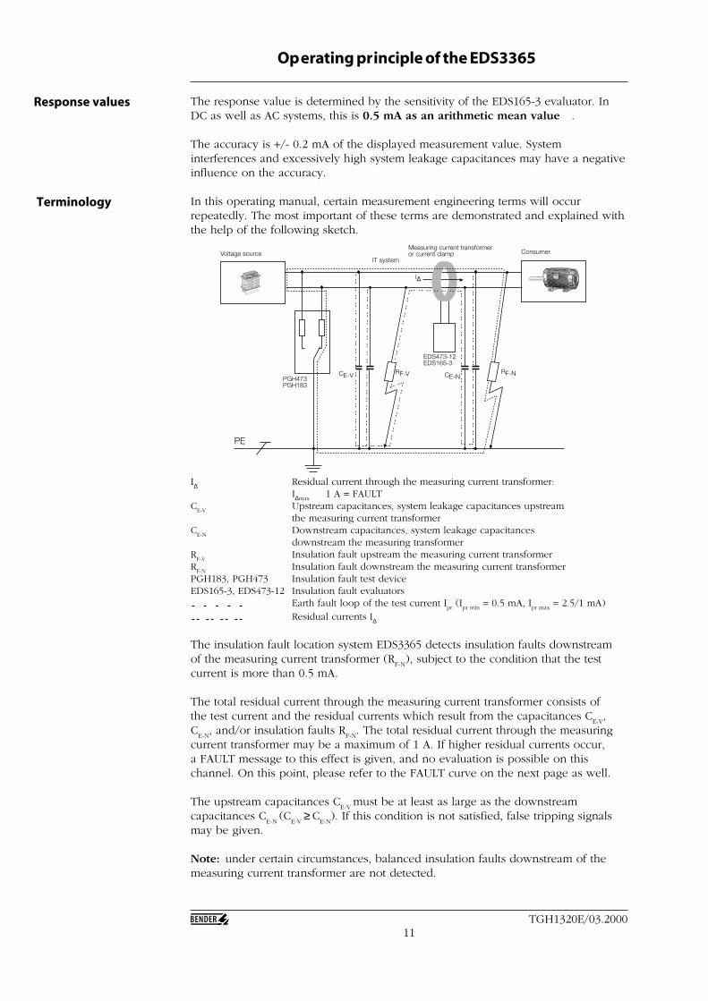
I∆ Residual current through the measuring current transformer:I∆max
1 A = FAULTC
E-VUpstream capacitances, system leakage capacitances upstreamthe measuring current transformer
CE-N
Downstream capacitances, system leakage capacitancesdownstream the measuring transformer
RF-V
Insulation fault upstream the measuring current transformerR
F-NInsulation fault downstream the measuring current transformer
PGH183, PGH473 Insulation fault test deviceEDS165-3, EDS473-12 Insulation fault evaluators
Earth fault loop of the test current Ipr (I
pr min = 0.5 mA, I
pr max = 2.5/1 mA)
Residual currents I∆
The insulation fault location system EDS3365 detects insulation faults downstreamof the measuring current transformer (R
F-N), subject to the condition that the test
current is more than 0.5 mA.
The total residual current through the measuring current transformer consists ofthe test current and the residual currents which result from the capacitances C
E-V,
CE-N
, and/or insulation faults RF-N
. The total residual current through the measuringcurrent transformer may be a maximum of 1 A. If higher residual currents occur,a FAULT message to this effect is given, and no evaluation is possible on thischannel. On this point, please refer to the FAULT curve on the next page as well.
The upstream capacitances CE-V
must be at least as large as the downstreamcapacitances C
E-N (C
E-V ≥
C
E-N). If this condition is not satisfied, false tripping signals
may be given.
Note: under certain circumstances, balanced insulation faults downstream of themeasuring current transformer are not detected.
Voltage source ConsumerIT system
Measuring current transformeror current clamp
EDS473-12EDS165-3
PGH473PGH183
PE
RF-NRF-V CE-NCE-V
I∆
The response value is determined by the sensitivity of the EDS165-3 evaluator. InDC as well as AC systems, this is 0.5 mA as an arithmetic mean value .
The accuracy is +/- 0.2 mA of the displayed measurement value. Systeminterferences and excessively high system leakage capacitances may have a negativeinfluence on the accuracy.
In this operating manual, certain measurement engineering terms will occurrepeatedly. The most important of these terms are demonstrated and explained withthe help of the following sketch.
Response values
Terminology
12TGH1320E/03.2000
Operating principle of the EDS3365
A sophisticated filter circuit and electronic system avoids malfunctions due toextraneous currents < 1 A.
The following FAULT conditions may be indicated on the display of the EDS165-3:
• Short circuited current clamp or current transformer connection. Display: no • Interrupted current transformer connection, or no current clamp or current
transformer connected. Display: no • A residual current > 1 A through the current clamp or the current transformer.• The current transformer signal cannot be evaluated due to interferences.• The leakage capacitances in the system, or in an output of the system, are too
high.
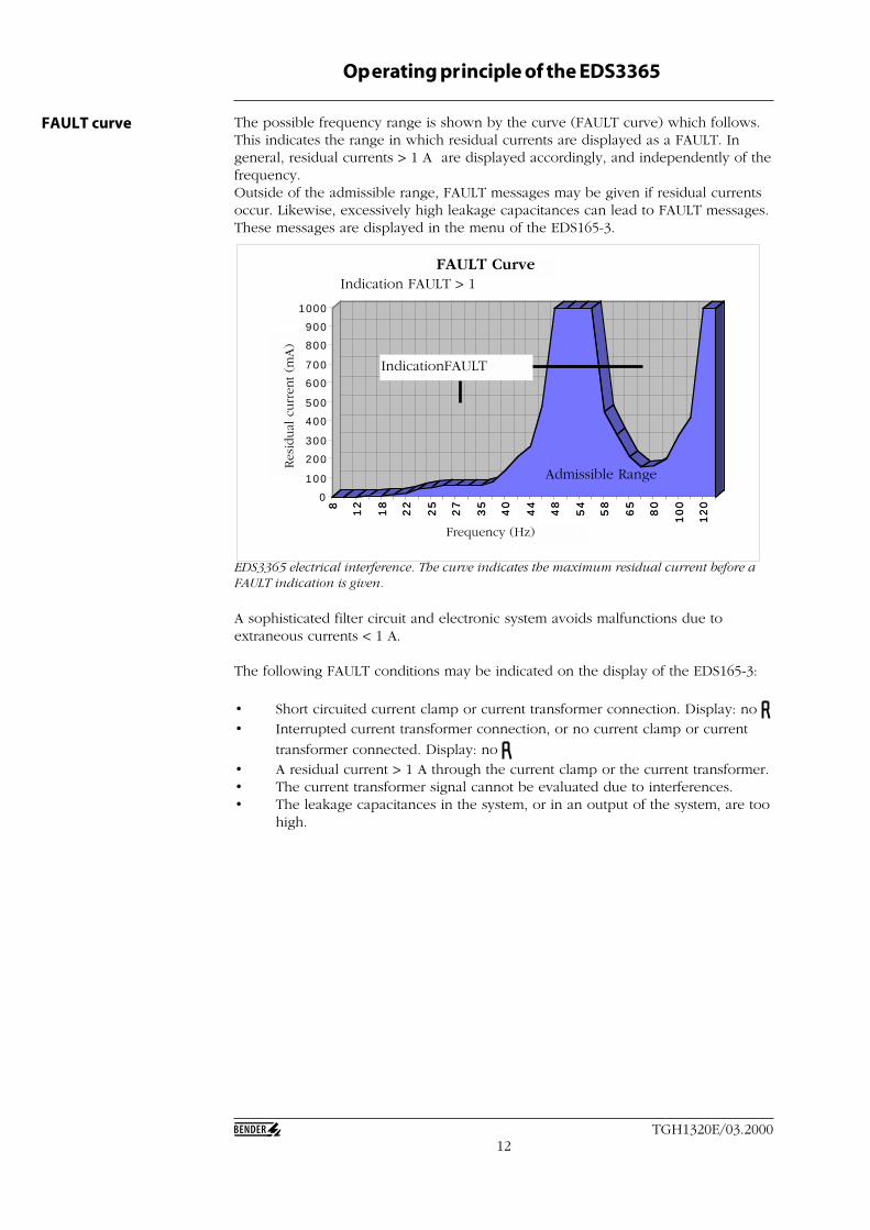
EDS3365 electrical interference. The curve indicates the maximum residual current before aFAULT indication is given.
8
12
18
22
25
27
35
40
44
48
54
58
65
80
10
0
12
0
0
100
200
300
400
500
600
700
800
900
1000
Dif
fere
nzs
tro
m
(mA
)
8
12
18
22
25
27
35
40
44
48
54
58
65
80
10
0
12
0
Frequenz (Hz)
FAULT-Kurve
Admissible Range
Indication FAULT > 1
The possible frequency range is shown by the curve (FAULT curve) which follows.This indicates the range in which residual currents are displayed as a FAULT. Ingeneral, residual currents > 1 A are displayed accordingly, and independently of thefrequency.Outside of the admissible range, FAULT messages may be given if residual currentsoccur. Likewise, excessively high leakage capacitances can lead to FAULT messages.These messages are displayed in the menu of the EDS165-3.
FAULT curve
IndicationFAULT
FAULT Curve
Frequency (Hz)
Res
idual
curr
ent (m
A)
13TGH1320E/03.2000
Operating principle of the EDS3365
I∆=0
PE
I fromIto
PSA3
352
MES
SZAN
GE
/ C
LAM
P O
N P
ROBE
Date
nbla
tt /
Data
shee
t : T
GH
1320
Durc
hmes
ser /
Dia
met
er :
52 m
m
Art.-
Nr.
/ Ar
t.-no
. : B
980
695
max
. 1 A
600
V C
AT II
I
1000
mA
/ 0,
1 m
A ~
I∆=0
PE
PSA3
352
MES
SZAN
GE
/ C
LAM
P O
N P
ROBE
Date
nbla
tt /
Data
shee
t : T
GH
1320
Durc
hmes
ser /
Dia
met
er :
52 m
m
Art.-
Nr.
/ Ar
t.-no
. : B
980
695
max
. 1 A
600
V C
AT II
I
1000
mA
/ 0,
1 m
A ~
I fromIto
RF
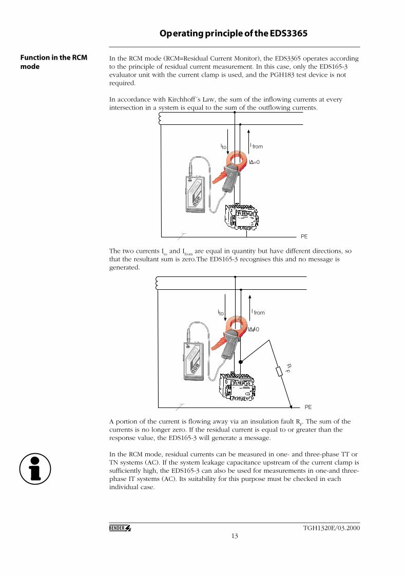
The two currents Ito and I
from are equal in quantity but have different directions, so
that the resultant sum is zero.The EDS165-3 recognises this and no message isgenerated.
In the RCM mode (RCM=Residual Current Monitor), the EDS3365 operates accordingto the principle of residual current measurement. In this case, only the EDS165-3evaluator unit with the current clamp is used, and the PGH183 test device is notrequired.
In accordance with Kirchhoff´s Law, the sum of the inflowing currents at everyintersection in a system is equal to the sum of the outflowing currents.
Function in the RCMmode
A portion of the current is flowing away via an insulation fault RF. The sum of the
currents is no longer zero. If the residual current is equal to or greater than theresponse value, the EDS165-3 will generate a message.
In the RCM mode, residual currents can be measured in one- and three-phase TT orTN systems (AC). If the system leakage capacitance upstream of the current clamp issufficiently high, the EDS165-3 can also be used for measurements in one-and three-phase IT systems (AC). Its suitability for this purpose must be checked in eachindividual case.
14TGH1320E/03.2000
Operating principle of the EDS3365
PSA3
352
MES
SZAN
GE
/ CL
AMP
ON
PRO
BE
Date
nbla
tt /
Data
shee
t : T
GH1
320
Durc
hmes
ser /
Dia
met
er :
52 m
m
Art.-
Nr.
/ Ar
t.-no
. : B
980
695
max
. 1 A
600
V C
AT II
I
1000
mA
/ 0,
1 m
A ~
PGH183
100m
A 1 m
A
2,5m
A Imax
ON
ON
Us
L1(+
)
L2(-)
L3AC/DC
Voltage source Consumer
Direction of energy
Insulation fault downstreamof the current clamp
Insulation fault upstreamof the current clamp
Direction of energy
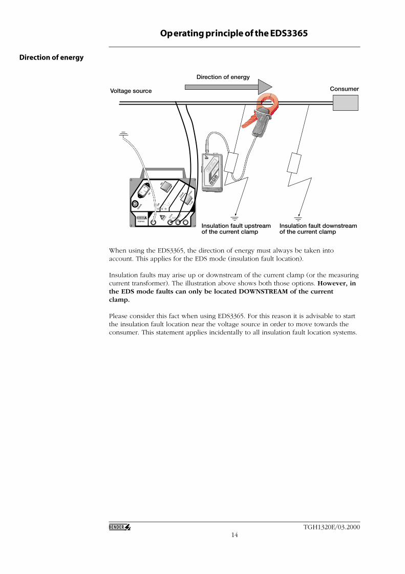
When using the EDS3365, the direction of energy must always be taken intoaccount. This applies for the EDS mode (insulation fault location).
Insulation faults may arise up or downstream of the current clamp (or the measuringcurrent transformer). The illustration above shows both those options. However, inthe EDS mode faults can only be located DOWNSTREAM of the currentclamp.
Please consider this fact when using EDS3365. For this reason it is advisable to startthe insulation fault location near the voltage source in order to move towards theconsumer. This statement applies incidentally to all insulation fault location systems.
15TGH1320E/03.2000
PSA3
352
MES
SZAN
GE
/ C
LAM
P O
N P
ROBE
Date
nbla
tt /
Data
shee
t : T
GH
1320
Durc
hmes
ser /
Dia
met
er :
52 m
m
Art.-
Nr.
/ Ar
t.-no
. : B
980
695
max
. 1 A
600
V C
AT II
I
1000
mA
/ 0,
1 m
A ~
4 Produc t description
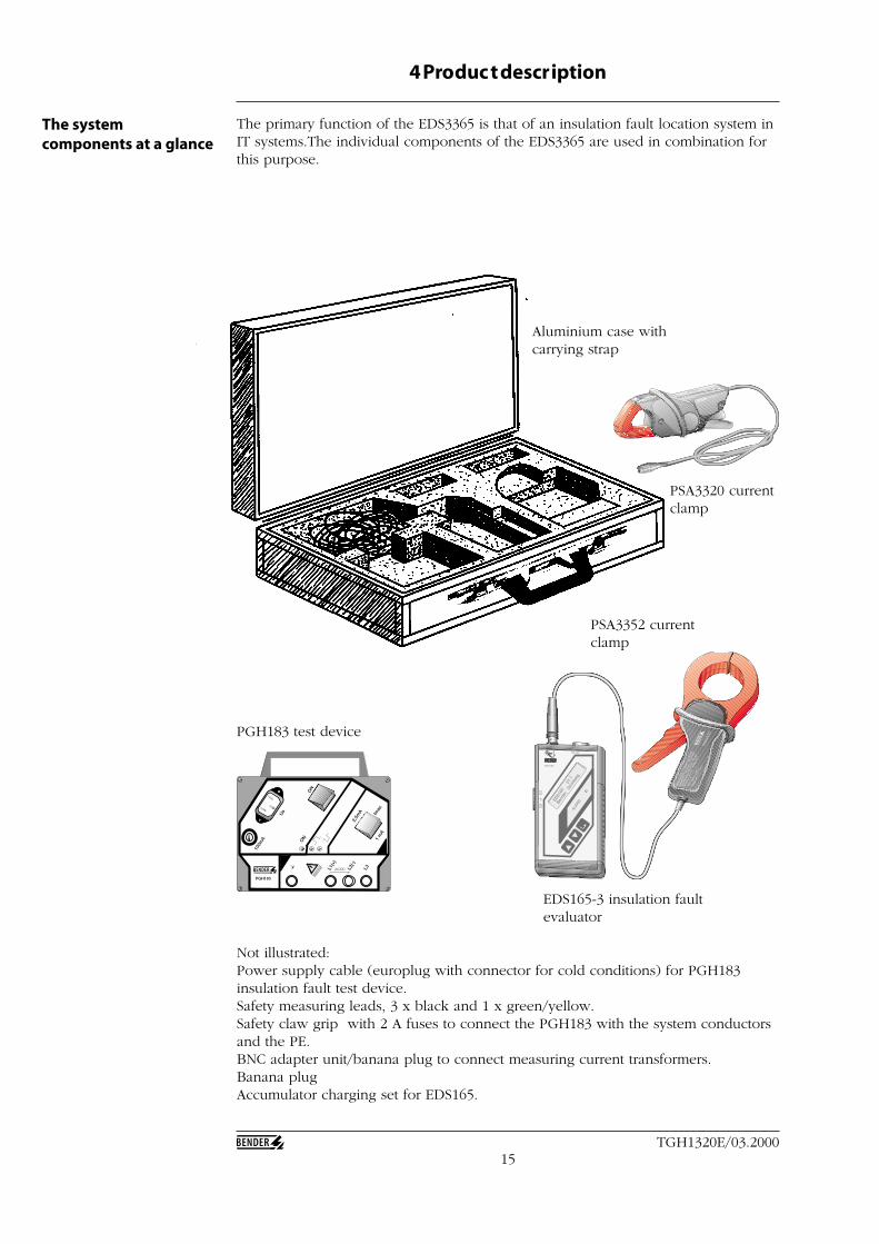
The primary function of the EDS3365 is that of an insulation fault location system inIT systems.The individual components of the EDS3365 are used in combination forthis purpose.
The systemcomponents at a glance
PGH183
100m
A 1 m
A
2,5m
A Imax
ON
ON
Us
L1(+
)
L2(-)
L3AC/DC
Aluminium case withcarrying strap
PSA3320 currentclamp
PSA3352 currentclamp
EDS165-3 insulation faultevaluator
PGH183 test device
Not illustrated:Power supply cable (europlug with connector for cold conditions) for PGH183insulation fault test device.Safety measuring leads, 3 x black and 1 x green/yellow.Safety claw grip with 2 A fuses to connect the PGH183 with the system conductorsand the PE.BNC adapter unit/banana plug to connect measuring current transformers.Banana plugAccumulator charging set for EDS165.
PSA3320
16TGH1320E/03.2000
Product description
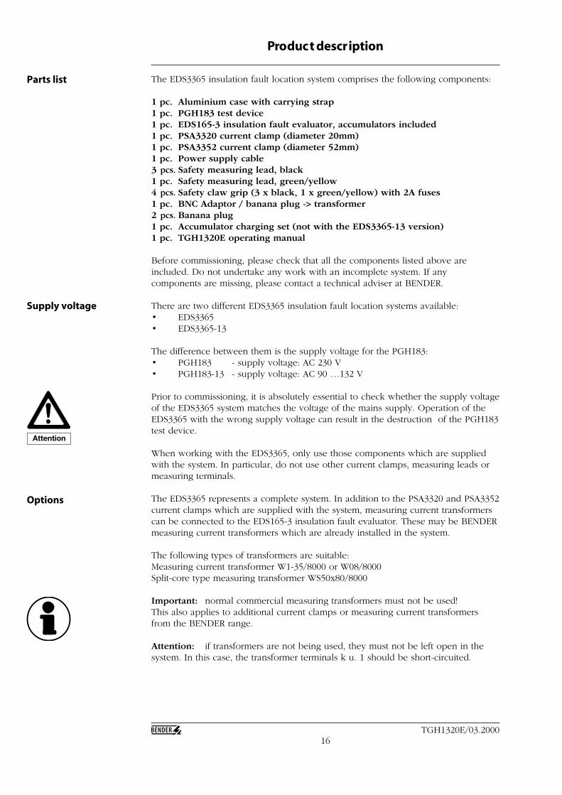
Parts list The EDS3365 insulation fault location system comprises the following components:
1 pc. Aluminium case with carrying strap1 pc. PGH183 test device1 pc. EDS165-3 insulation fault evaluator, accumulators included1 pc. PSA3320 current clamp (diameter 20mm)1 pc. PSA3352 current clamp (diameter 52mm)1 pc. Power supply cable3 pcs. Safety measuring lead, black1 pc. Safety measuring lead, green/yellow4 pcs. Safety claw grip (3 x black, 1 x green/yellow) with 2A fuses1 pc. BNC Adaptor / banana plug -> transformer2 pcs. Banana plug1 pc. Accumulator charging set (not with the EDS3365-13 version)1 pc. TGH1320E operating manual
Before commissioning, please check that all the components listed above areincluded. Do not undertake any work with an incomplete system. If anycomponents are missing, please contact a technical adviser at BENDER.
There are two different EDS3365 insulation fault location systems available:• EDS3365• EDS3365-13
The difference between them is the supply voltage for the PGH183:• PGH183 - supply voltage: AC 230 V• PGH183-13 - supply voltage: AC 90 …132 V
Prior to commissioning, it is absolutely essential to check whether the supply voltageof the EDS3365 system matches the voltage of the mains supply. Operation of theEDS3365 with the wrong supply voltage can result in the destruction of the PGH183test device.
When working with the EDS3365, only use those components which are suppliedwith the system. In particular, do not use other current clamps, measuring leads ormeasuring terminals.
The EDS3365 represents a complete system. In addition to the PSA3320 and PSA3352current clamps which are supplied with the system, measuring current transformerscan be connected to the EDS165-3 insulation fault evaluator. These may be BENDERmeasuring current transformers which are already installed in the system.
The following types of transformers are suitable:Measuring current transformer W1-35/8000 or W08/8000Split-core type measuring transformer WS50x80/8000
Important: normal commercial measuring transformers must not be used!This also applies to additional current clamps or measuring current transformersfrom the BENDER range.
Attention: if transformers are not being used, they must not be left open in thesystem. In this case, the transformer terminals k u. 1 should be short-circuited.
Supply voltage
Options
Attention
17TGH1320E/03.2000
Ope
rati
ng
mod
ese
lect
or s
wit
ch
Product description
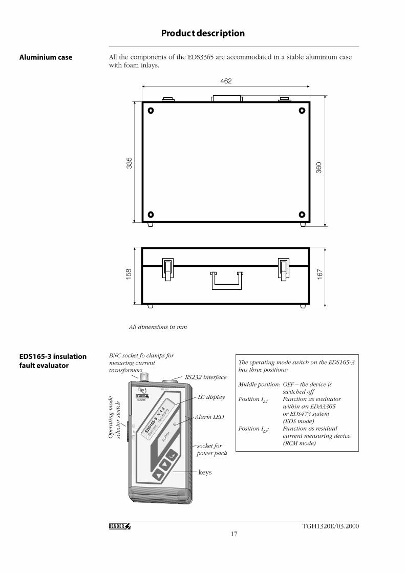
Aluminium case All the components of the EDS3365 are accommodated in a stable aluminium casewith foam inlays.
462
335
360
158
167
EDS165
EDS1
65-3
V. 1
.5
EDS165-3 insulationfault evaluator
BNC socket fo clamps formesuring currenttransformers
RS232 interface
Alarm LED
socket forpower pack
keys
LC display
The operating mode switch on the EDS165-3has three positions:
Middle position: OFF – the device isswitched off
Position I∆S: Function as evaluator
within an EDA3365or EDS473 system(EDS mode)
Position I∆N: Function as residual
current measuring device(RCM mode)
All dimensions in mm
18TGH1320E/03.2000
Product description
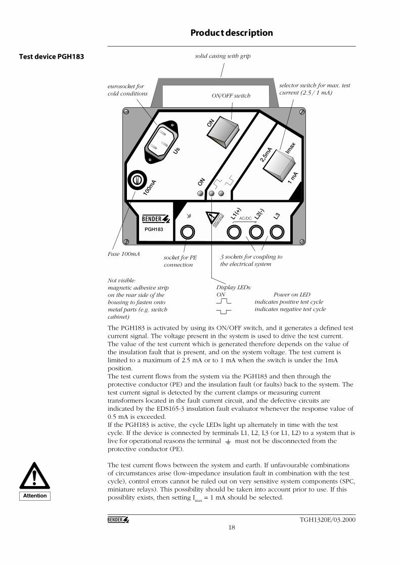
Test device PGH183
PGH183
100m
A 1 m
A
2,5m
A Imax
ON
ON
Us
L1(+
)
L2(-)
L3AC/DC
solid casing with grip
ON/OFF switch
eurosocket forcold conditions
Fuse 100mAsocket for PEconnection
3 sockets for coupling tothe electrical system
Display LEDs:ON Power on LED
indicates positive test cycleindicates negative test cycle
selector switch for max. testcurrent (2.5 / 1 mA)
The PGH183 is activated by using its ON/OFF switch, and it generates a defined testcurrent signal. The voltage present in the system is used to drive the test current.The value of the test current which is generated therefore depends on the value ofthe insulation fault that is present, and on the system voltage. The test current islimited to a maximum of 2.5 mA or to 1 mA when the switch is under the 1mAposition.The test current flows from the system via the PGH183 and then through theprotective conductor (PE) and the insulation fault (or faults) back to the system. Thetest current signal is detected by the current clamps or measuring currenttransformers located in the fault current circuit, and the defective circuits areindicated by the EDS165-3 insulation fault evaluator whenever the response value of0.5 mA is exceeded.If the PGH183 is active, the cycle LEDs light up alternately in time with the testcycle. If the device is connected by terminals L1, L2, L3 (or L1, L2) to a system that islive for operational reasons the terminal must not be disconnected from theprotective conductor (PE).
The test current flows between the system and earth. If unfavourable combinationsof circumstances arise (low-impedance insulation fault in combination with the testcycle), control errors cannot be ruled out on very sensitive system components (SPC,miniature relays). This possibility should be taken into account prior to use. If thispossiblity exists, then setting I
max = 1 mA should be selected.
Not visible:magnetic adhesive stripon the rear side of thehousing to fasten ontometal parts (e.g. switchcabinet)
Attention
19TGH1320E/03.2000
Product description
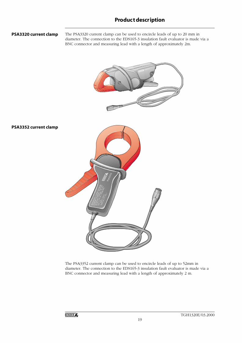
PSA3320 current clamp The PSA3320 current clamp can be used to encircle leads of up to 20 mm indiameter. The connection to the EDS165-3 insulation fault evaluator is made via aBNC connector and measuring lead with a length of approximately 2m.
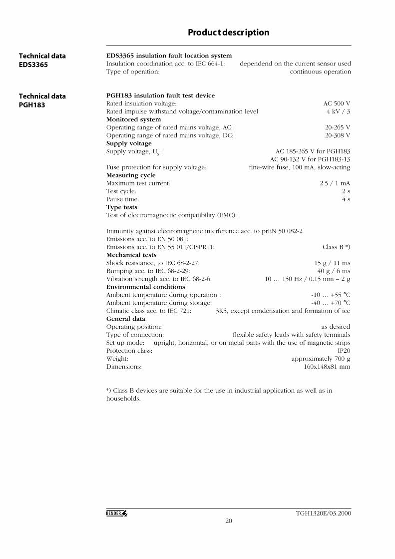
PSA3352 current clamp
The PSA3352 current clamp can be used to encircle leads of up to 52mm indiameter. The connection to the EDS165-3 insulation fault evaluator is made via aBNC connector and measuring lead with a length of approximately 2 m.
PSA3320
PSA3
352
MES
SZAN
GE
/ C
LAM
P O
N P
ROBE
Date
nbla
tt /
Data
shee
t : T
GH
1320
Durc
hmes
ser /
Dia
met
er :
52 m
m
Art.-
Nr.
/ Ar
t.-no
. : B
980
695
max
. 1 A
600
V C
AT II
I
1000
mA
/ 0,
1 m
A ~
20TGH1320E/03.2000
Product description
EDS3365 insulation fault location systemInsulation coordination acc. to IEC 664-1: dependend on the current sensor usedType of operation: continuous operation
PGH183 insulation fault test deviceRated insulation voltage: AC 500 VRated impulse withstand voltage/contamination level 4 kV / 3Monitored systemOperating range of rated mains voltage, AC: 20-265 VOperating range of rated mains voltage, DC: 20-308 VSupply voltageSupply voltage, U
S: AC 185-265 V for PGH183
AC 90-132 V for PGH183-13Fuse protection for supply voltage: fine-wire fuse, 100 mA, slow-actingMeasuring cycleMaximum test current: 2.5 / 1 mATest cycle: 2 sPause time: 4 sType testsTest of electromagnectic compatibility (EMC):
Immunity against electromagnetic interference acc. to prEN 50 082-2Emissions acc. to EN 50 081:Emissions acc. to EN 55 011/CISPR11: Class B *)Mechanical testsShock resistance, to IEC 68-2-27: 15 g / 11 msBumping acc. to IEC 68-2-29: 40 g / 6 msVibration strength acc. to IEC 68-2-6: 10 … 150 Hz / 0.15 mm – 2 gEnvironmental conditionsAmbient temperature during operation : -10 … +55 °CAmbient temperature during storage: -40 … +70 °CClimatic class acc. to IEC 721: 3K5, except condensation and formation of iceGeneral dataOperating position: as desiredType of connection: flexible safety leads with safety terminalsSet up mode: upright, horizontal, or on metal parts with the use of magnetic stripsProtection class: IP20Weight: approximately 700 gDimensions: 160x148x81 mm
*) Class B devices are suitable for the use in industrial application as well as inhouseholds.
Technical dataPGH183
Technical dataEDS3365
21TGH1320E/03.2000
Product description
Technical dataEDS165-3
Insulation coordination acc. to DIN VDE 0110 T1: depends on the current clamp usedType of operation: continuous operation
Monitored system:Rated insulation voltage U
n: see PGH183 and/or current clamps
System frequency in EDS mode: 50,60,400 Hz (adjustable) or DCSystem frequency in RCM mode: 47 … 65 Hz
Supply voltageOperating range supply voltage U
S: DC 4.2 … 6.2 V
Supply: via 4 round cells, type LR6 AA – 1.5 V or 4 NC cells, 1.2 V, or via power unitFor supply via external power unit: DC 7.5 VImax
: 100 mAPolarity:
Operating lifetime of the batteries: minimum 8hPower consumption: 0.6 W
Measurement input for IDs
- function (EDS mode in combination withEDS473 systems)Response value: 0.5 mAAccuracy: +/- 0.2 mA
Measurement input for I∆n- function (RCM mode, residual current
measurement)Measuring range with current clamps: AC 10 mA … 1.6 AMeasuring range with measuring current transformers: AC 10 mA … 1 AResponse range for alarm indication: AC 10 mA … 1 AAccuracy: +/- 10 %
Weight: approximately 370 g
Current clamps:Insulation coordination acc. to IEC 1010-2-032Nominal insulation voltage, PSA3320 and PSA3352: AC 600 V CAT III
and AC 300 V CAT IVProtection class acc. to DIN 40 050 IP40Measurement output BNC plugDimensions, PSA3352 216x111x45 mmDimensions, PSA3320 135x65x30 mm
Permissible cable diameter, PSA3352 : 52 mmPermissible cable diameter, PSA3320 : 20 mm
Weight, PSA3352 : approximately 550 gWeight, PSA3320 : approximately 200 g
+ -
Technical datacurrent clamps
22TGH1320E/03.2000
5 Op eration and S etting
Factory settings The components of the EDS3365 are delivered with factory settings, which aresuitable for many standard applications. The following list shows the factory settingsfor the individual devices:
PGH183 test deviceImax
= 2.5 mA
EDS165-3 insulation fault evaluator (with the switch in position I∆s)
Fault memory: offBuzzer: onFrequency: 50 HzSensor: current clamp PSA3320
Except for the changeover of the maximum test current, all the settings to theEDS3365 systems are performed on the EDS165-3 insulation fault evaluator.
Settings on theEDS165-3 evaluator
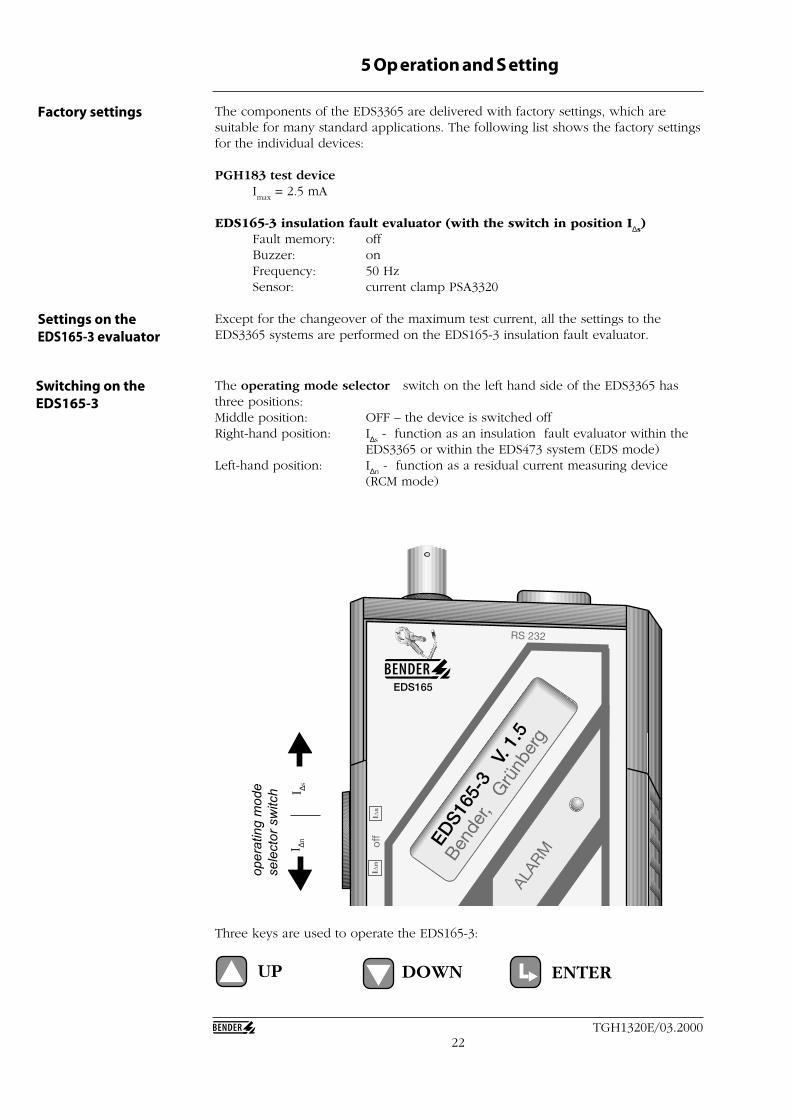
The operating mode selector switch on the left hand side of the EDS3365 hasthree positions:Middle position: OFF – the device is switched offRight-hand position: I∆s
- function as an insulation fault evaluator within theEDS3365 or within the EDS473 system (EDS mode)
Left-hand position: I∆n - function as a residual current measuring device
(RCM mode)
Switching on theEDS165-3
Three keys are used to operate the EDS165-3:
UP DOWN ENTER
op
era
tin
g m
od
e
se
lecto
r sw
itch
I ∆nI ∆s
EDS165
EDS1
65-3
V. 1
.5
23TGH1320E/03.2000
Operation and S etting
The EDS165-3display
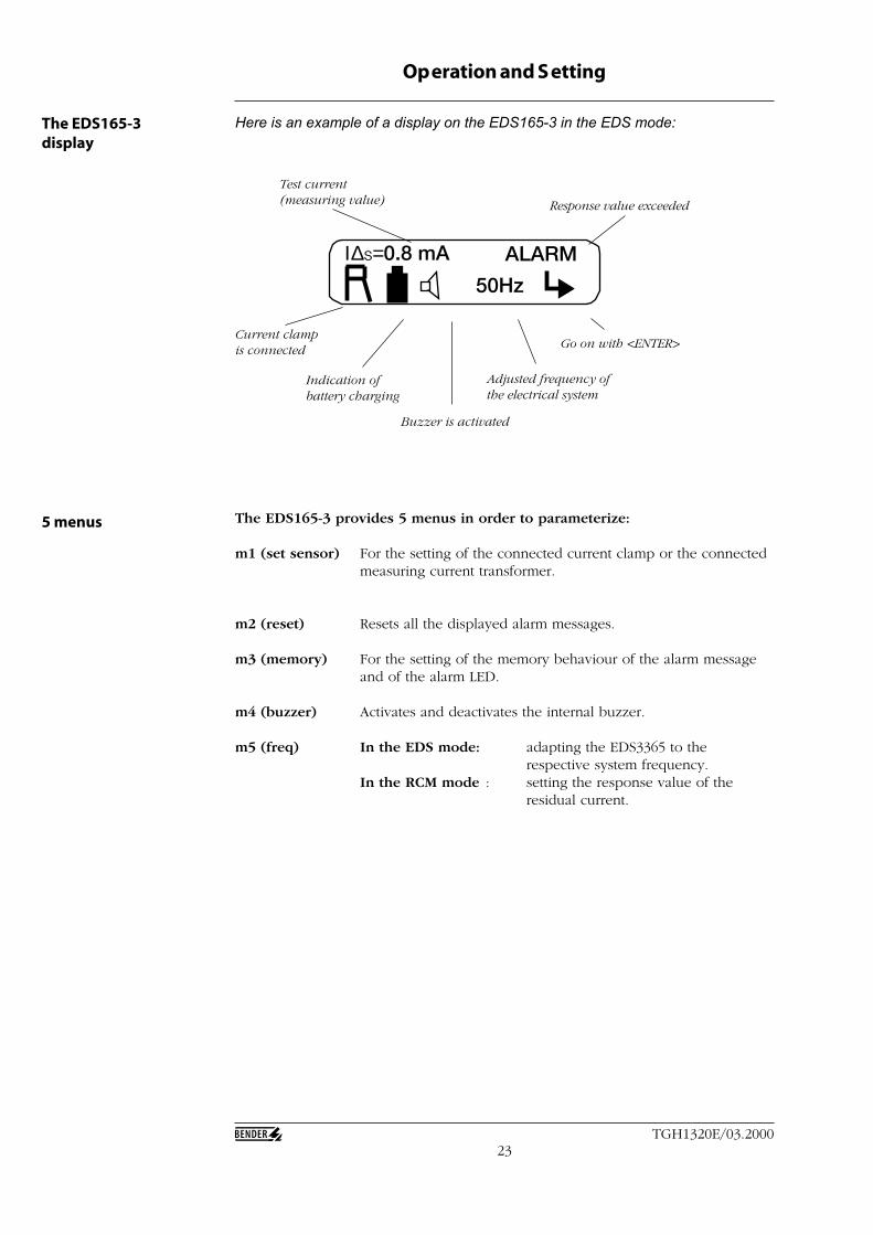
Here is an example of a display on the EDS165-3 in the EDS mode:
Ι∆s=0.8 mA ALARM
50Hz
The EDS165-3 provides 5 menus in order to parameterize:
m1 (set sensor) For the setting of the connected current clamp or the connectedmeasuring current transformer.
m2 (reset) Resets all the displayed alarm messages.
m3 (memory) For the setting of the memory behaviour of the alarm messageand of the alarm LED.
m4 (buzzer) Activates and deactivates the internal buzzer.
m5 (freq) In the EDS mode: adapting the EDS3365 to therespective system frequency.
In the RCM mode : setting the response value of theresidual current.
5 menus
Current clampis connected
Indication ofbattery charging
Buzzer is activated
Adjusted frequency ofthe electrical system
Go on with <ENTER>
Response value exceeded
Test current(measuring value)

24TGH1320E/03.2000
Operation and S etting
The EDS165-3 is operated and set using three control keys and the LCD display.When making any of the settings, you must press the relevant control keys for about1 second. The different settings which are possible in the EDS mode (position I∆s
)are described below.If you move the operating mode selector switch to position I∆s
the EDS 165-3 will bein the EDS mode. As soon as you have done this, you will see the display menu(see above).
From the display menu, press the <ENTER> key to reach the setting menus. The<ENTER> key activates whichever sub-menu you have called up; use the <UP> keyto move to the next menu.
Press the <ENTER> key to implementthe selected setting and return to thedisplay mode; use the <UP> key toselect reset or no reset.
The EDS165-3 inthe EDS mode
m2: reset
m3: m1: ,
no reset:
reset: alarm
The next menu (m2) is the reset menu.Press:<ENTER> to call up the reset program,<UP> to call up the next menu (m3) or<down> to return to the previous menu(m1).
The sensor which is set at present is thePSA3320 current clamp. The possiblesettings are described below. Press:<ENTER> to accept the current settingand return to the display mode,<UP/DOWN> to select the current clampor measuring current transformers.
Menu 1 (m1) allows you to set thesensor which is connected. Press:<ENTER> to reach the menu formodification,<UP> to move on to the next menu, m2or <down> to return to the displaymode.
m1: set sensor
m2:exit: ,
sensor: ,
sensor: ok:
The following settings are possible:
Menu 1: set sensor
Menu 2: reset
PSA3352 current clamp
PSA3320 current clamp
Standard measuring current transformers:W1-35/8000W08/8000
Split-core measuring currenttransformers WS50x80/8000
25TGH1320E/03.2000
Operation and S etting
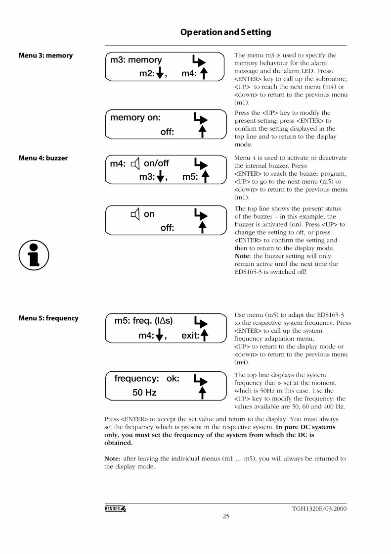
Use menu (m5) to adapt the EDS165-3to the respective system frequency. Press<ENTER> to call up the systemfrequency adaptation menu,<UP> to return to the display mode or<down> to return to the previous menu(m4).
The top line displays the systemfrequency that is set at the moment,which is 50Hz in this case. Use the<UP> key to modify the frequency: thevalues available are 50, 60 and 400 Hz.
m5: freq. (I∆s)
exit: m4: ,
50 Hz
frequency: ok:
Press <ENTER> to accept the set value and return to the display. You must alwaysset the frequency which is present in the respective system. In pure DC systemsonly, you must set the frequency of the system from which the DC isobtained.
Note: after leaving the individual menus (m1 … m5), you will always be returned tothe display mode.
The menu m3 is used to specify thememory behaviour for the alarmmessage and the alarm LED. Press:<ENTER> key to call up the subroutine,<UP> to reach the next menu (m4) or<down> to return to the previous menu(m1).
m3: memory
m4: m2: ,
Press the <UP> key to modify thepresent setting; press <ENTER> toconfirm the setting displayed in thetop line and to return to the displaymode.
Menu 4 is used to activate or deactivatethe internal buzzer. Press:<ENTER> to reach the buzzer program,<UP> to go to the next menu (m5) or<down> to return to the previous menu(m1).
The top line shows the present statusof the buzzer – in this example, thebuzzer is activated (on). Press <UP> tochange the setting to off, or press<ENTER> to confirm the setting andthen to return to the display mode.Note: the buzzer setting will onlyremain active until the next time theEDS165-3 is switched off!
off:
memory on:
on/offm4:m5: m3: ,
off:
on
Menu 3: memory
Menu 4: buzzer
Menu 5: frequency
26TGH1320E/03.2000
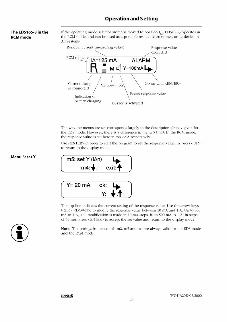
The way the menus are set corresponds largely to the description already given forthe EDS mode. However, there is a difference in menu 5 (m5). In the RCM mode,the response value is set here in mA or A respectively.
Use <ENTER> in order to start the program to set the response value, or press <UP>to return to the display mode.
The top line indicates the current setting of the response value. Use the arrow keys(<UP>, <DOWN>) to modify the response value between 10 mA and 1 A. Up to 500mA to 1 A, the modification is made in 10 mA steps; from 500 mA to 1 A, in stepsof 50 mA. Press <ENTER> to accept the set value and return to the display mode.
Note: The settings in menus m1, m2, m3 and m4 are always valid for the EDS modeand the RCM mode.
The EDS165-3 in theRCM mode
Operation and S etting
If the operating mode selector switch is moved to position I∆n, EDS165-3 operates in
the RCM mode, and can be used as a portable residual current measuring device inAC systems.
Residual current (measuring value) Response valueexceeded
Go on with <ENTER>
Preset response value
Buzzer is activated
Current clampis connected
Indication ofbattery charging
Memory = on
RCM mode Ι∆=125 mA ALARMY=100mAM
m5: set Y (I∆n)
exit: m4: ,
Y: ,
Y= 20 mA ok:
Menu 5: set Y

27TGH1320E/03.2000
Operation and S etting
The EDS165-3 issues a fault message if no current clamps or measuring currenttransformers are connected. The fault message is given acoustically and visually. TheBUZZER ON or BUZZER OFF setting does not influence the acoustic message if nocurrent clamp is present. The message is given in the EDS mode as well as the RCMmode.Attention: no fault message is given if an incorrect current clamp or an incorrectmeasuring current transformer are connected. In this case the indications of testcurrent and residual current can be quite different.
When the response value is exceeded in the RCM mode (I∆n), this is shown on the
display by the ALARM message and indication of the residual current.
In the EDS mode (I∆s), a selective test
current which is greater than 0.5 mAwill result in an alarm message.
In the top line, I∆n shows the currently
measured residual current; and in thelower line, Y shows the responsevalue that has been set.
Residual currents that are greater than1 A lead to different messages. In theEDS mode, a FAULT message isgenerated:
In the RCM mode, an ALARMmessage is generated:
no
Ι∆=125 mA ALARM
Y=100mAM
Ι∆s=1.5 mA ALARM
50HzM
Ι∆ >1.0 A FAULT
50HzM
Ι∆ >1.0 A ALARM
Y=100 mAM
If there is no current clamp connected to the system or if there is a short-circuit inthe line of the current clamp, the display shows: no
When internal faults or high EMC interferences occur, it may be that no recognitionof the set mode is possible anymore. In this case a general fault message isdisplayed. This indication may occur also in the case of an empty accumulator.
No FunctionCall BENDER Service
Call ++ - 6401 - 807 - 0 for technicalsupport.
28TGH1320E/03.2000
Serial interface The standard RS232 interface makes it possible to connect system independentcomponents. These may be computer systems, stored-program controllers, or similaritems. With knowledge of the interface protocol being used, it is possible for theuser to write his own programs and use them. The protocol for data transmissioncorresponds to the format for BENDER measuring device interfaces.
Data transmission generally makes use of ASCII characters. The interface data are:
Baud rate: 9600 baudTransmission: 1 start bit, 7 data bits, 1 parity bit, 1 stop bit (1,7,E,1)Parity: even (P=0)Checksum: sum of all transmitted bytes = 0 (without CR and LF)Address: 001 … 255 and 000 (=general address)
Protocols:Master :;XXX:ABCDE 12345&XYZ<CR><LF>Slave ::XXX:ABCDE 12345&XYZ<CR><LF>
:; recognition of start of master transmission:: recognition of start of slave transmissionXXX address: start byte for commandABCDE command, consisting of a maximum of 5 ASCII characters(blank character) start byte for data12345 data, consisting of a maximum of 5 ASCII characters,
maximum size: 65 535& start byte for checksumXYZ checksum, consisting of a maximum of 3 ASCII characters<CR><LF> end of transmission (carriage return, line feed)
The command and the data may be smaller than 5 bytes, or may be omittedaltogether. In every case, the end is recognised from the start byte to the nextcharacter type.
Interface protocol
Operation and S etting
29TGH1320E/03.2000
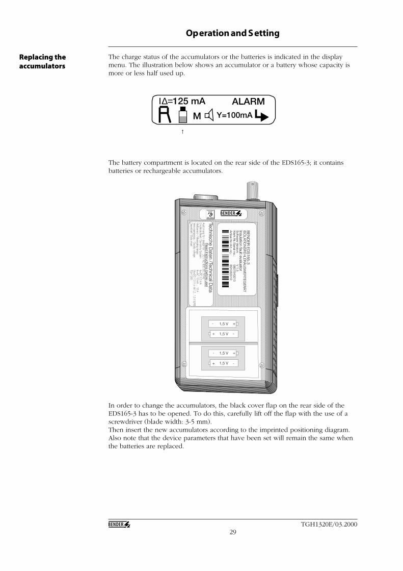
The charge status of the accumulators or the batteries is indicated in the displaymenu. The illustration below shows an accumulator or a battery whose capacity ismore or less half used up.
The battery compartment is located on the rear side of the EDS165-3; it containsbatteries or rechargeable accumulators.
In order to change the accumulators, the black cover flap on the rear side of theEDS165-3 has to be opened. To do this, carefully lift off the flap with the use of ascrewdriver (blade width: 3-5 mm).Then insert the new accumulators according to the imprinted positioning diagram.Also note that the device parameters that have been set will remain the same whenthe batteries are replaced.
1,5 V
1,5 V
1,5 V
1,5 V
+
+
+
+ -
-
-
-
BE
ND
ER
ED
S165-3
ISO
LATION
SFE
HLE
RA
US
WE
RTE
GE
RÄ
TInsulation fault evaluatorS
oftware Version:
V 1.5
Werk-N
r./Serial-no.:
9907049213A
rtikel-Nr./A
rt.-no.:B
91082010
Technische Daten /Technical D
ataR
ead Instructions before use!Ausführung für / design for:
DC / AC 400, 60, 50 HzEm
pfindlichkeit / Sensitivity System:
Is=DC 0,5 mA
Meßbereich / M
easuring range:In=AC 10 m
A ... 16 AVersorgungsspg. / Supply voltage:
Us=DC 7,5 V or 4x1,2...1,5 V (LR6)Datenblatt / Data sheet:
TGH1265
Quality SystemCertified
I S O 9 0 0 1
Replacing theaccumulators
Operation and S etting
Ι∆=125 mA ALARMY=100mAM
↑
30TGH1320E/03.2000
6 Points to be considered b efore use
The EDS3365 makes it possible to search for insulation faults in IT systems, AC 20-265 V and DC 20-308 V. This system is particularly well suited for use in controlvoltage systems where control errors may be caused as a result of high faultcurrents; this is due to the special features of the EDS3365, such as:
• low test current => no control errors• high sensitivity• relatively insensitive to system leakage capacitances and faults• long time measurement• data transmission with possibility of evaluation
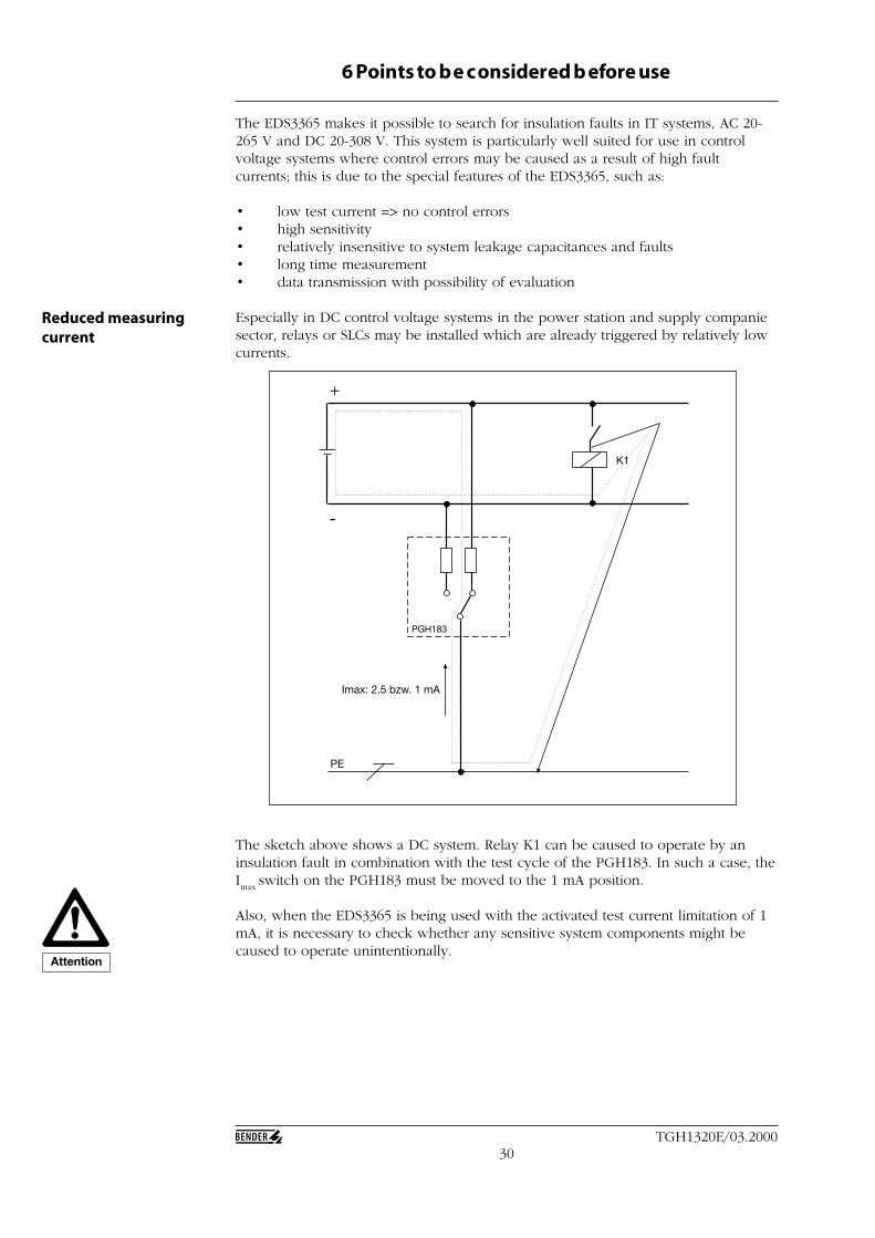
Especially in DC control voltage systems in the power station and supply companiesector, relays or SLCs may be installed which are already triggered by relatively lowcurrents.
+
-
DC
PE
PGH183
K1
Imax: 2.5 bzw. 1 mA
The sketch above shows a DC system. Relay K1 can be caused to operate by aninsulation fault in combination with the test cycle of the PGH183. In such a case, theImax
switch on the PGH183 must be moved to the 1 mA position.
Also, when the EDS3365 is being used with the activated test current limitation of 1mA, it is necessary to check whether any sensitive system components might becaused to operate unintentionally.
Reduced measuringcurrent
Attention
31TGH1320E/03.2000
Points to be considered before use
The sensitivity of the EDS3365 is 0.5 mA. Hence the maximum insulation resistancewhich can be deteced is dependent on the voltage wave form, the level of thevoltage and the system leakage capacitance that is present.
In order to start insulation faults location in a sensible manner, it is advisable toconsult the following characteristic curves beforehand. These show:
• the insulation fault which can be found, in relation to the system voltage(curve 1)
• the maximum permissible system leakage capacitance, in relation to thesystem voltage (curve 2)
• the reduction in response sensitivity when system leakage capacitances arehigher (curve 3)
An example:
In a 110 V DC IT system, the insulation monitoring device which is already presentshows an insulation fault of 500 kΩ. The system leakage capacitances are less than0.1 µF and are therefore negligible.A look at characteristic curve 1 shows that an insulation fault of about 200 kΩ canbe found in a DC system with 110 V. Therefore it makes no sense in this case to startinsulation fault location with the EDS3365.
Another example:
In a 230 V AC IT system, the insulation monitoring device which is already presentshows an insulaion fault of 100 kΩ. Characteristic curve 1 shows that in a 230 V DCsystem, an insulaion fault can be found from about 200 kΩ upwards. Therefore inthis case, it makes sense to start insulation fault location, and the chances of findingthe fault are very good.
As a basic rule, it is necessary to take account of the possibility that the totalinsulation resistance of a system is made up from the parallel connection of severalinsulation faults. It is not known which individual faults contribute to this.If a fault is not found with the EDS3365, even though this ought to be the caseaccording to the characteristic curves, the cause may be the sum of a number ofindividual faults. In this instance, none of the individual faults is of sufficiently lowimpedance that it can be detected by the EDS3365.
Another reason why insulation faults are not found may be an excessively highsystem leakage capacitance (on this point, see characteristic curves). Whenconsidering the system leakage capacitances, a point to note is that the division tothe capacitances upstream and downstream of the current clamp is not arbitrary.The upstream capacitance of the entire system must account for at least 50% of thetotal capacitance. Otherwise a reduction in the response sensitivity must beexpected.
A sensible approachto fault location

32TGH1320E/03.2000
Points to be considered before use
Curve 1: response value Rf in relation to the system voltage (AC 20-265 V andDC 20-308 V) with a maximum system leakage capacitance C
e as
shown by curve 2.
Characteristic curves
0
100
200
300
400
500
600
700
0 5 0 100 150 200 250 300 350
Un (V)
Rf
(kΩ
)
AC
DC
0
1
2
3
4
5
6
7
0 100 200 300 400
Un (V)
Ce
(µ
F)
AC
DC
Curve 2: maximum permissible system leakage capacitance in relation tothe nominal voltage (AC 20-265 V, DC 20-308 V). Up to thissystem leakage capacitance, the EDS3365 has the sensitivityshown in curve 1.
DC: set the test currentto 2.5 mA or 1 mA
AC: set the testcurrent to 2.5 mA
AC: set the testcurrent to 2.5 mA
DC: set the test current to 2.5 mA or 1 mA
33TGH1320E/03.2000
Points to be considered before use
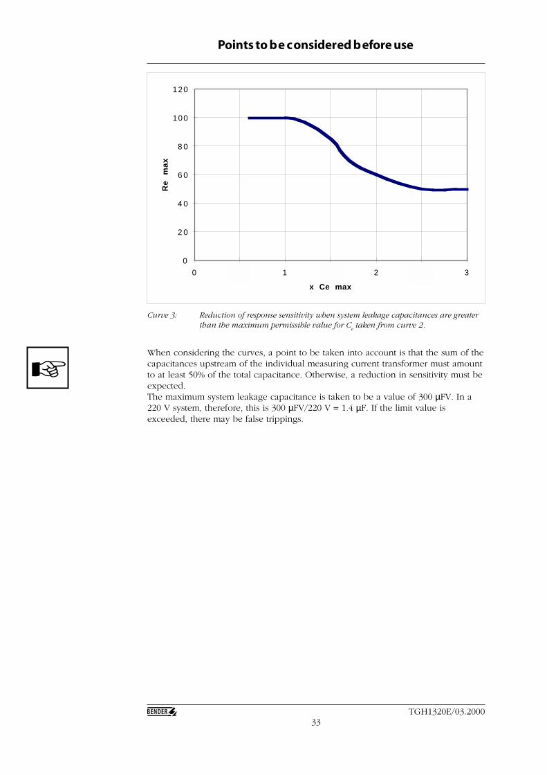
Curve 3: Reduction of response sensitivity when system leakage capacitances are greaterthan the maximum permissible value for C
e taken from curve 2.
When considering the curves, a point to be taken into account is that the sum of thecapacitances upstream of the individual measuring current transformer must amountto at least 50% of the total capacitance. Otherwise, a reduction in sensitivity must beexpected.The maximum system leakage capacitance is taken to be a value of 300 µFV. In a220 V system, therefore, this is 300 µFV/220 V = 1.4 µF. If the limit value isexceeded, there may be false trippings.
0
2 0
4 0
6 0
8 0
100
120
0 0 , 5 1 1 , 5 2 2 , 5 3
x Ce max
Re
m
ax

34TGH1320E/03.2000
Points to be considered before use
All the charcteristic curves on the foregoing pages are valid for the indicated testcurrents.
Limitation of the test current to 1 mA is particulary intended for the use of theEDS3365 in DC control systems with consumers which may already operate at verylow currents. If the test current is activated in AC systems, the maximum test currentis then reduced to factor 0.5 in AC systems or 0.67 in 3AC systems respectively. Ofcourse, these factors are valid for a maximum test current of 2.5 mA as well.Recommendation: select 2.5 mA as the setting for the test current in AC systems.
It is a well-known fact that everything in this world has its limits.This principle evenapplies to the measurement technique of the EDS3365. Modern suppply systemsnowadays contain a large number of components which may lead to influences andfaults.
Interferences for the EDS 3365 system are for example:• high system leakage capacitances• excessively high leakage currents• transient leakage currents• low-frequency leakage currents
The limit conditions are cited in this operating manual. However, because of thelarge number of possibilities, we cannot make unambiguous statements about everytype of interference compatibility, nor about functional limits. In case of doubt, youmust clarify the suitablility of the EDS3365 for the application in question byconsulting a BENDER adviser.
The conditions, and the reactions of the EDS3365 if the conditions are exceeded,should be explained at this point:
• Response sensitivity: for this purpose, curve 3 in this chapter should be takeninto account.
• Influence of system leakage capacitances: curve 2 in this chapter shows theresponse sensitivity dependent on the leakage capacitance of the total system.If the leakage capacitance exceeds the permissible value in one subcircuitdownstream of the current clamp, incorrect messages may appear on theEDS165-3 evaluator.
• Maximum leakage currents: the maximum permissible system-dependentleakage current under which the evaluation will still function properly islimited to 1 A. If the leakage current exceeds 1 A, selective fault location canno longer be undertaken. Leakage currents > 1 A are shown by the indication(I∆
> 1 A) in the display of the EDS165-3.• Transient leakage currents: switching and controlling activities in the system
may generate transient leakage currents which influence the evaluation of thetest signal. These transient leakage currents can only be filtered out to acertain extent. It cannot be ruled out that periodic interferences which happento have the same periodic duration, amplitude and signal frequency as theinternal signal scanning may result in faulty measurements and may thereforelead to false trippings. However, the probability of this happening isextremely low. It is not possible to give a precise definition of these limitconditions because they depend on the nature of the system.
• Low-frequency leakage currents: these may be brought about by the use offrequency converters. They may lead to false trippings on the EDS165-3 iftheir frequency is equal to, or approximately equal to the test cycle frequencyof the test device (PGH473, PGH183).
Limits of insulationfault location
35TGH1320E/03.2000
7 Practical use
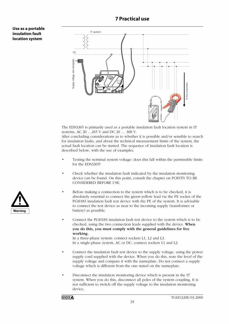
The EDS3365 is primarily used as a portable insulation fault location system in ITsystems, AC 20 …265 V and DC 20 … 308 V.After concluding considerations as to whether it is possible and/or sensible to searchfor insulation faults, and about the technical measurement limits of the system, theactual fault location can be started. The sequence of insulation fault location isdescribed below, with the use of examples.
• Testing the nominal system voltage: does this fall within the permissible limitsfor the EDS3365?
• Check whether the insulation fault indicated by the insulation monitoringdevice can be found. On this point, consult the chapter on POINTS TO BECONSIDERED BEFORE USE.
• Before making a connection to the system which is to be checked, it isabsolutely essential to connect the green-yellow lead via the PE socket of thePGH183 insulation fault test device with the PE of the system. It is advisableto connect the test device as near to the incoming supply (transformer orbattery) as possible.
• Connect the PGH183 insulation fault test device to the system which is to bechecked, using the two connection leads supplied with the device. Whenyou do this, you must comply with the general guidelines for liveworking.In a three-phase system: connect sockets L1, L2 and L3.In a single-phase system, AC or DC: connect sockets L1 and L2.
• Connect the insulation fault test device to the supply voltage, using the powersupply cord supplied with the device. When you do this, note the level of thesupply voltage and compare it with the nameplate. Do not connect a supplyvoltage which is different from the one stated on the nameplate.
• Disconnect the insulation monitoring device which is present in the ITsystem. When you do this, disconnect all poles of the system coupling. It isnot sufficient to switch off the supply voltage to the insulation monitoringdevice.
Use as a portableinsulation faultlocation system
PSA3
352
MES
SZAN
GE
/ CL
AMP O
N PR
OBE
Daten
blatt /
Dat
ashe
et : T
GH1
320
Durch
messe
r / D
iame
ter :
52 m
m
Art.-N
r. /
Art.-n
o. :
B 98
0 69
5
max.
1 A
600
V C
AT III
1000
mA
/ 0,
1 mA
~
PGH183
100m
A 1 m
A
2,5m
A Imax
ON
ON
Us
L1(+
)
L2(-)
L3AC/DC
PE
IT system
To th
e co
nsum
ers
Supp
ly vo
ltage
, see
nam
epla
te
Warning
36TGH1320E/03.2000
Practical use
• Check the switch position Imax
on the PGH183. The factory setting is 2.5 mA. If theIT system contains components which might already operate at low currents, then itmay be necessary to select the 1 mA switch position. Note: the maximum testcurrent flows between the system and earth, not as a load current. Undesiredoperation is therefore only possible if an insulation fault is combined with the testcycle. Note: in AC systems set 2.5 mA, in DC systems 2.5 or 1 mA.
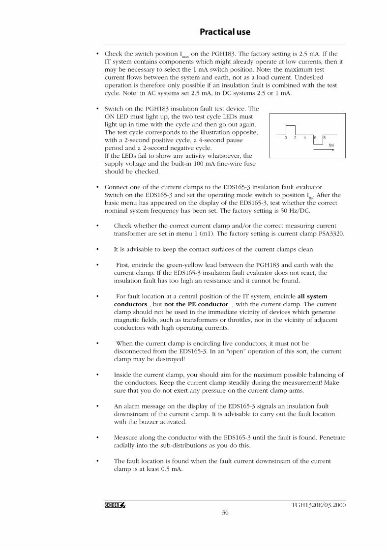
• Switch on the PGH183 insulation fault test device. TheON LED must light up, the two test cycle LEDs mustlight up in time with the cycle and then go out again.The test cycle corresponds to the illustration opposite,with a 2-second positive cycle, a 4-second pauseperiod and a 2-second negative cycle.If the LEDs fail to show any activity whatsoever, thesupply voltage and the built-in 100 mA fine-wire fuseshould be checked.
• Connect one of the current clamps to the EDS165-3 insulation fault evaluator.Switch on the EDS165-3 and set the operating mode switch to position I∆s
. After thebasic menu has appeared on the display of the EDS165-3, test whether the correctnominal system frequency has been set. The factory setting is 50 Hz/DC.
0 2 4 6 8
t(s)
• Check whether the correct current clamp and/or the correct measuring currenttransformer are set in menu 1 (m1). The factory setting is current clamp PSA3320.
• It is advisable to keep the contact surfaces of the current clamps clean.
• First, encircle the green-yellow lead between the PGH183 and earth with thecurrent clamp. If the EDS165-3 insulation fault evaluator does not react, theinsulation fault has too high an resistance and it cannot be found.
• For fault location at a central position of the IT system, encircle all systemconductors , but not the PE conductor , with the current clamp. The currentclamp should not be used in the immediate vicinity of devices which generatemagnetic fields, such as transformers or throttles, nor in the vicinity of adjacentconductors with high operating currents.
• When the current clamp is encircling live conductors, it must not bedisconnected from the EDS165-3. In an "open” operation of this sort, the currentclamp may be destroyed!
• Inside the current clamp, you should aim for the maximum possible balancing ofthe conductors. Keep the current clamp steadily during the measurement! Makesure that you do not exert any pressure on the current clamp arms.
• An alarm message on the display of the EDS165-3 signals an insulation faultdownstream of the current clamp. It is advisable to carry out the fault locationwith the buzzer activated.
• Measure along the conductor with the EDS165-3 until the fault is found. Penetrateradially into the sub-distributions as you do this.
• The fault location is found when the fault current downstream of the currentclamp is at least 0.5 mA.
37TGH1320E/03.2000
For operating currents < 1 AC, measurement is also possible by encircling oneconductor only. Attention: for DC currents > 10 A, this may produce the effect thatthe current clamp can no longer be opened. This danger is particularly present indirect current sytems. If this behaviour occurs, under no circumstances use force,since this would destroy the current clamp. Instead, you must switch off the relevantsystem. After this has been done, the current clamp can be opened without theapplication of force.
Practical use
Using the EDS165-3within an EDS473system
The EDS165-3 insulation fault evaluator can also be used without the PGH183 testdevice within a system such as an EDS473, as a permanently installed system. In thiscase, it detects the test pulses from the PGH473 test device. Insulation faultevaluation is only possible in live IT systems.The practical use of the EDS165-3 within a permanently installed EDS473 insulationfault location system is described below:
• The central insulation monitoring device has signalled an insulation faultbelow its response value.
• The insulation monitoring device has to be disconnected from the systemwith all poles.
• The insulation fault location system is activated by pressing the START key ofthe PGH473 and it starts fault location; the test device is clocking. Theinsulation fault evaluation continues as long as the test device is clocking.
• Connect the current clamp (or the measuring current transformer) via a BNCadapter.
• Move the operating mode switch of the EDS165-3 to the I∆s position; wait
until the basic menu appears on the display.
• Check whether the correct nominal system frequency is set. The factorysetting for the frequency is 50 Hz.
• Check whether the correct current clamp and/or the correct measuringcurrent transformer are set in menu 1 (m1 – set sensor). The factory setting iscurrent clamp PSA3320.
• At subcircuits where no measuring current transformer is installed, ordownstream of installed measuring current transformers, fault location cannow be continued with the EDS165-3.Attention: do not connect the core of the current clamp to system voltagesabove the nominal insulation voltage.
• All system conductors, but not the PE , must be encircled by the currentclamp.Attention: do not encircle any shielded leads!
• When the current clamp is encircling live conductors, it must not bedisconnected from the EDS165-3. In this type of ”open” operation, the currentclamp may be destroyed!
• During the measurement, the current clamp must be held steadily. Theconductors should be encircled as symmetrically as possible. Make sure thatyou do not exert any pressure on the arms of the current clamp. An alarmmessage is given within 30 seconds after closing of the current clamp.
38TGH1320E/03.2000
Practical use
A1 A2 K1 K2 K3 K4 K5 K6 K7 K8 K9
A B R1 R2 l K12 K11 K10 11 12 14
onoff
RS485TEST
RESETFAULTALARMON A4 A3 A2 A1 A0
K12K11K10K9K8K7K6K5K4K3K2K1I∆s
SLAVE ADDRESS
MONITORA1 A2 GND IN1 IN2 IN3 IN4 O1+ O1- O2+ O2-
A B 21 22 2411
PRC470
12 14
ALARM RS485RS485
EDS-System
IT system (AC 20-265 V or DC 20-308 V)
PRC470
PGH473
EDS473-12
RS485 Bus
Disconnect theinsulation monitoring deviceduring the fault locationfrom the system!
EDS start
A1 A2 11 14 L1 L2 L3
A B GND IN1 IN2 E
10
RS485STARTSTOPON 2.5mA A3 A2 A1 A0
PGH473
SLAVE ADDRESS + 110
GENERATOR
SLAVE
MASTER1 mA
IN3
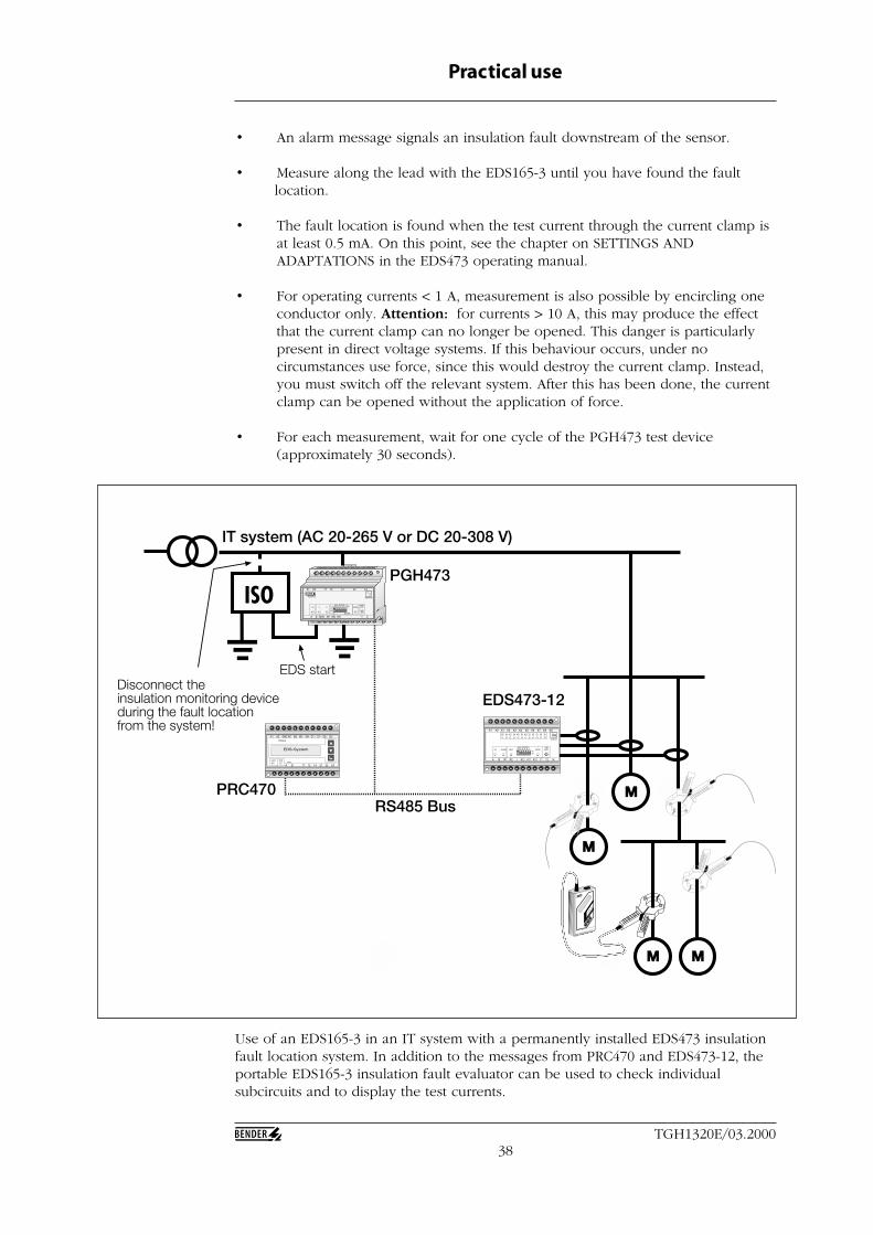
Use of an EDS165-3 in an IT system with a permanently installed EDS473 insulationfault location system. In addition to the messages from PRC470 and EDS473-12, theportable EDS165-3 insulation fault evaluator can be used to check individualsubcircuits and to display the test currents.
• An alarm message signals an insulation fault downstream of the sensor.
• Measure along the lead with the EDS165-3 until you have found the faultlocation.
• The fault location is found when the test current through the current clamp isat least 0.5 mA. On this point, see the chapter on SETTINGS ANDADAPTATIONS in the EDS473 operating manual.
• For operating currents < 1 A, measurement is also possible by encircling oneconductor only. Attention: for currents > 10 A, this may produce the effectthat the current clamp can no longer be opened. This danger is particularlypresent in direct voltage systems. If this behaviour occurs, under nocircumstances use force, since this would destroy the current clamp. Instead,you must switch off the relevant system. After this has been done, the currentclamp can be opened without the application of force.
• For each measurement, wait for one cycle of the PGH473 test device(approximately 30 seconds).
39TGH1320E/03.2000
Practical use
Using the EDS165-3 as aresidual current monitor
The EDS165-3 can also be used without the PGH183 test device as a residual currentmeasuring device in TN and TT systems, and provided that certain systemconditions are fulfilled, it can also operate in IT systems. The residual currentmeasurement is only possible in live systems.
• Test whether the system is live.
• Connect the current clamp.
• Move the operating mode selector switch on the EDS165-3 to position I∆n,
and wait until the basic menu appears on the display.
• Check whether the correct current clamp is set in menu 1 (m1 – set sensor).The factory setting is current clamp PSA3320.
• Check whether an response value (I∆n = XX mA) has been set which is
suitable for practical purposes. The factory setting is a response value of 100mA.
• Start measurement at a suitable position in the system. When you do this,start as near to the incoming supply as possible and move on radially in thedirection of the consumers.
• During the measurement, the current clamp must be held steadily. Theconductors should be encircled as symmetrically as possible. Make sure thatyou do not exert any pressure on the arms of the current clamp.
• During measurement, encircle all the system conductors, but not the PE .Do not encircle any shielded leads.
• When the current clamp is encircling live conductors, it must not bedisconnected from the EDS165-3. In this type of ”open” operation, the currentclamp may be destroyed!
• The residual current at each measuring point is shown on the display. If theresidual current is greater than the set response value, an acoustic signal willalso be given provided that the buzzer is activated.
• For long time measurements at one point of the system, the fault memorymust be activated (memory on) in menu 3 (m3 – memory). In this way, it isalso possible to find intermittent residual currents, provided that they arehigher than the set response value.The highest measured residual current is stored.
40TGH1320E/03.2000
Practical use
Insulation fault locationwith the EDS3365 indiode-decoupled systems
PSA3
352
MES
SZAN
GE
/ CL
AMP
ON
PRO
BE
Date
nbla
tt /
Data
shee
t : T
GH1
320
Durc
hmes
ser /
Dia
met
er :
52 m
m
Art.-
Nr.
/ Ar
t.-no
. : B
980
695
max
. 1 A
600
V C
AT II
I
1000
mA
/ 0,
1 m
A ~
PGH183
100m
A 1 m
A
2,5m
A Imax
ON
ON
Us
L1(+
)
L2(-)
L3AC/DC
Voltage source Consumer
Direction of energy
Insulation fault downstreamof the current clamp
Insulation fault upstreamof the current clamp
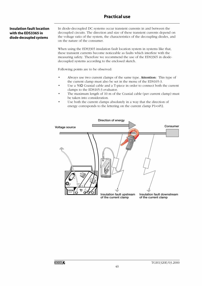
In diode-decoupled DC systems occur transient currents in and between thedecoupled circuits. The direction and size of these transient currents depend onthe voltage ratio of the system, the characteristics of the decoupling diodes, andon the nature of the consumer.
When using the EDS3365 insulation fault location system in systems like that,these transient currents become noticeable as faults which interfere with themeasuring safety. Therefore we recommend the use of the EDS3365 in diode-decoupled systems according to the enclosed sketch.
Following points are to be observed:
• Always use two current clamps of the same type. Attention: This type ofthe current clamp must also be set in the menu of the EDS165-3.
• Use a 50Ω Coaxial cable and a T-piece in order to connect both the currentclamps to the EDS165-3 evaluator.
• The maximum length of 10 m of the Coaxial cable (per current clamp) mustbe taken into consideration.
• Use both the current clamps absolutely in a way that the direction ofenergy corresponds to the lettering on the current clamp P1=>P2.
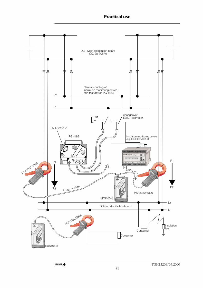
41TGH1320E/03.2000
Practical use
PSA3352
MESSZ
ANGE / C
LAMP O
N PROBE
Datenb
latt /
Data
sheet
: TGH1320
Durchm
esser
/ Diam
eter :
52 mm
Art.-Nr. /
Art.-
no. :
B 980 695
max. 1
A
600 V C
AT III
1000 mA /
0,1 mA ~
PSA3352
MESSZ
ANGE / C
LAMP O
N PROBE
Datenb
latt /
Data
sheet
: TGH1320
Durchm
esser
/ Diam
eter :
52 mm
Art.-Nr. /
Art.-
no. :
B 980 695
max. 1
A
600 V C
AT III
1000 mA /
0,1 mA ~
PSA3352
MESSZ
ANGE / C
LAMP O
N PROBE
Datenb
latt /
Data
sheet
: TGH1320
Durchm
esser
/ Diam
eter :
52 mm
Art.-Nr. /
Art.-
no. :
B 980 695
max. 1
A
600 V C
AT III
1000 mA /
0,1 mA ~
PGH183
100m
A 1 m
A
2,5m
A Imax
ON
ON
Us
L1(+
)
L2(-)
L3AC/DC
KE M+ M <LT> <PT> AB
A-ISOMETER®Serie 260
1 ALARM 2
A1(+) A2(-) AKL3L2L1
242221141211
(L/+) (L/-)
TESTRESET
kΩMONITOR
L- L+
L+
L-
PGH183
S1changeoverEDS/A-Isometer
Insulation monitoring devicee.g. IRDH265/365-3
DC - Main distribution board(DC 20-308 V)
Central coupling ofinsulation monitoring deviceand test device PGH183
Us AC 230 V
PSA3352/3320
PSA3352/3320
EDS165-3
DC Sub distribution board
l max. = 10 m
l max. =
10m
L+
L-
Consumer
Insulationfault
Consumer
EDS165-3
PSA3352/3320
P1
P2
P1
P2
42TGH1320E/03.2000
Practical use
Sequence of theinsulation fault location
• The central insulation monitoring device has signalled an insulation faultthat is below the insulation value the EDS system is able to locate. Pleaseobserve the characteristic curves with it in chapter ”Points to be consideredbefore use”.
• Reading the relevant insulation restistance on the LC display of theinsulation monitoring device:Is the read value of the insulation resistance smaller than the maximuminsulation fault of the EDS system that can be localized, change from theISOMETER to the EDS mode using S1.
• Connecting the PGH183 to the test current feeding points according to theenclosed sketch.
• Preparing the EDS163 evaluator:• Connect the two current clamps of similar construction (PSA3352, PSA3320)
to the BNC extension leads and to the BNC adaptor.• Switch the operating mode selector switch to the EDS mode (I∆n
).• Carry out the following software settings:
menu m1: set sensor to the current clamp in use (PSA3352,PSA3320)
menu m3: memory offmenu m4: onmenu m5: frequency 50 Hz
• Start of the EDS systemFirst encircle the PE conductor of the PGH183 with one of the twoconnected current clamps. When the measured test current I∆s
on the LC-Display of the EDS165-3 exceeds 1 mA, then a successful location of theinsulation fault is possible.Afterwards disconnect the current clamp from the PE conductor.Now run the L+ and the L- through the current clamps, under nocircumstances through the PE conductor though.
• Insulation fault location in the installation with the EDS system:Encircle the two redundant supply conductors leading to the consumers,each with one current clamp. When you do this, take into considerationthat you really encircle the supply conductors belonging to the sameconsumer. Pay attention to the identical direction of energy of both currentclamps (see sketch). Encircle all the parallel consumer subcircuits with thecurrent clamps. Consumer subcircuits with insulation faults will be indicatedby an alarm message on theEDS165-3.Attention: An alarm message occurs approximately 30 seconds afterconnecting both the current clamps.
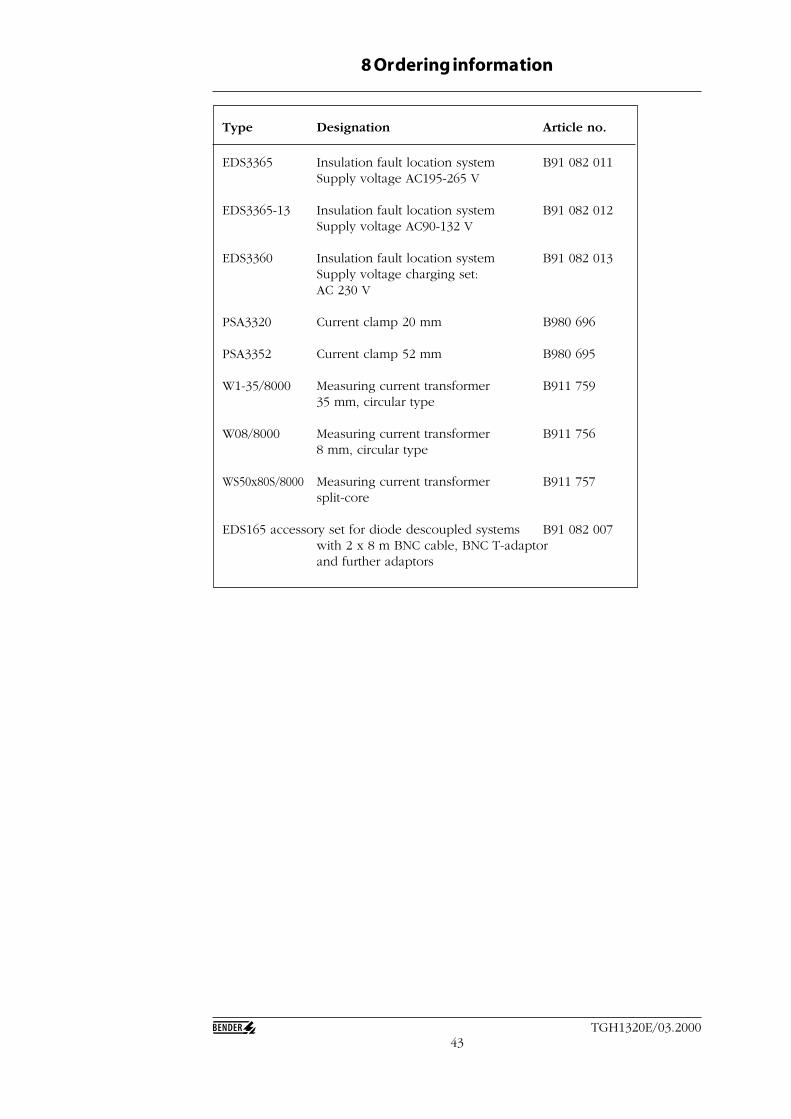
43TGH1320E/03.2000
8 Ordering information
Type Designation Article no.
EDS3365 Insulation fault location system B91 082 011Supply voltage AC195-265 V
EDS3365-13 Insulation fault location system B91 082 012Supply voltage AC90-132 V
EDS3360 Insulation fault location system B91 082 013Supply voltage charging set:AC 230 V
PSA3320 Current clamp 20 mm B980 696
PSA3352 Current clamp 52 mm B980 695
W1-35/8000 Measuring current transformer B911 75935 mm, circular type
W08/8000 Measuring current transformer B911 7568 mm, circular type
WS50x80S/8000 Measuring current transformer B911 757split-core
EDS165 accessory set for diode descoupled systems B91 082 007with 2 x 8 m BNC cable, BNC T-adaptorand further adaptors