
PRODUKTKATALOG I - feba-systeme.com · 40 wINKELGREIFARmE ANGULAR ARMS • Sehr stabile und...
75
Ausgabe 09/2016 PRODUKTKATALOG | PRODUCT CATALOGUE PRODUKTKATALOG I Ausgabe 09/2016 PRODUCT CATALOGUE
Transcript of PRODUKTKATALOG I - feba-systeme.com · 40 wINKELGREIFARmE ANGULAR ARMS • Sehr stabile und...

Ausgabe 09/2016
PRODUKTKATALOG | PRODUCT CATALOGUEPRODUKTKATALOG I
Ausgabe 09/2016
PRODUCT CATALOGU
E

www.feba-systeme.com4
Die FEBA AUTOMATION ist ein dynamisches, erfahre-nes und überaus engagiertes Team mit dem Ziel, Sie als Kunde in allen Belangen der Automatisierungstech-nik zufrieden zu stellen. Das primäre Bestreben von uns ist es, eine konstruktive und vertrauensvolle Beziehung aufzubauen und zu pflegen, um so eine langfristige Part-nerschaft mit Ihnen als Kunde zu erzielen. Das Verständ-nis für unsere Partner und die Bereitschaft unsererseits, immer etwas mehr zu leisten als Andere, ist die Basis für eine erfolgreiche Zusammenarbeit und eine positive Ge-schäftsentwicklung. Mit unserer langjährigen Erfahrung im Bereich „Automatisierung“ können Sie sicher sein, den richtigen Partner gefunden zu haben. Aufgrund der schlanken innerbetrieblichen Struktur sind wir in der Lage, Projekte innerhalb kürzester Zeit effizient zu realisieren, egal ob es sich um einen Einzelentnah-megreifer, aufwendige Projektpakete oder um komplexe Automatisierungsstrecken und Zuführungen handelt.
• Greiferbau | construction of grippers• Laserforming | laser-forming• Zuführsysteme | feeding systems• Prüfstationen | testing stands• Vorrichtungsbau | construction of devices and fixtures
• Förderbandsysteme | conveyor belt systems• Sondermaschinenbau | construction of special purpose machines• Angusstrennung | sprue separation
The aim of FEBA’s AUTOMATION dynamic, experienced and fully dedicated team is to satisfy you as our customer in all aspects of automation technology. Our primary goal is to estab-lish and maintain a constructive and trustful relationship in order to create a long-lasting partnership with you as our customer. Understanding our partners and demonstrating our willingness to always do our job better than the others form the basis for a successful cooperation and a positive business development. Due to our long-standing experience in automation techno-logy you can be sure that you have found the right partner. Due to our lean internal structure we are in a position to im-plement projects within a very short time frame, no matter whether the project concerns a single withdrawal gripper, exten-sive project packages or complex automation lines and feeding systems.
FEBA AUTOMATION - Ihr Partner für | your partner for

www.feba-systeme.com40
wINKELGREIFARmEANGULAR ARMS
• Sehr stabile und passgenaue Ausführung.• Very robust and accurately fitting construction.
Bezeichnung | item D1 D2 L MWGA10 - 10 - 30 10 10 30 7WGA10 - 10 - 60 10 10 60 7WGA10 - 10 - 90 10 10 90 7WGA14 - 14 - 40 14 14 40 11WGA14 - 14 - 80 14 14 80 11WGA14 - 14 - 120 14 14 120 11WGA20 - 20 - 50 20 20 50 13WGA20 - 20 - 100 20 20 100 13WGA20 - 20 - 150 20 20 150 13
• Technische Zeichnung | technical drawing
• Abbildung | picture WGA20 - 20 - 100
!
Winkelgreifarmezum Klemmen von Anbauteilen sowie zur Anbin-dung von Verlängerungen. Angular arms for clamping componentes and to connect extensions.

Maßangaben in mm | Dimensions in mm 4141
GREIFARmE sTUFENLos DREHbAR
• Sehr stabile und passgenaue Ausführung.• Sichere und stabile Klemmung des Winkels.• Very robust and accurately fitting construction.• Safe and stable mounting of the angle.
Bezeichnung | item D1 D2 L MGAS10 - 10 - 30 10 10 30 16GAS10 - 10 - 60 10 10 60 16GAS10 - 10 - 90 10 10 90 16GAS14 - 14 - 40 14 14 40 20GAS14 - 14 - 80 14 14 80 20GAS14 - 14 - 120 14 14 120 20GAS20 - 20 - 50 20 20 50 26GAS20 - 20 - 100 20 20 100 26GAS20 - 20 - 150 20 20 150 26
• Technische Zeichnung | technical drawing
• Abbildung | picture GAS20 - 20 - 100
!
Greifarme stufenlos drehbarzum Klemmen von Anbauteilen. Die Klemmung des stufenlosen Winkels geschieht mittels zweier Schrauben. Kein Verdrehen möglich. Swivelable angular arms for clamping componentes. The clamping of the variable angle is done by means of two screws. No twisting possible.
SwIVELAbLE ANGULAR ARMS

Maßangaben in mm | Dimensions in mm 5353
sAUGERADAPTER
SUcTION cUP ADAPTERS
• Technische Zeichnung | technical drawing
SaugeradapterBauteil dient zur optimalen Positionierung eines Vakuumsaugers inkl. Stopfen.
Bezeichnung | item A B C D ESA16 - 28 - G1/8 - G1/8 28 25 16 G1/8 G1/8SA20 - 28 - G1/4 - G1/4 28 30 20 G1/4 G1/4SA25 - 40 - G3/8 - G3/8 40 35 25 G3/8 G3/8
• Abbildung | picture SA20 - 28 - G1/4 - G1/4
• Sehr kleine Baugröße.• 3 x Anschlussmöglichkeiten.
• Very small size.• 3 connection possibilities.
Suction cup adapters The component is used for the optimum positioning of a vacuum suction cup incl. plug
!
www.feba-systeme.com54
sAUGERADAPTERSUcTION cUP ADAPTERS
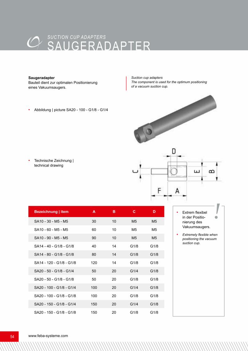
SaugeradapterBauteil dient zur optimalen Positionierung eines Vakuumsaugers.
Bezeichnung | item A B C DSA10 - 30 - M5 - M5 30 10 M5 M5SA10 - 60 - M5 - M5 60 10 M5 M5SA10 - 90 - M5 - M5 90 10 M5 M5SA14 - 40 - G1/8 - G1/8 40 14 G1/8 G1/8SA14 - 80 - G1/8 - G1/8 80 14 G1/8 G1/8SA14 - 120 - G1/8 - G1/8 120 14 G1/8 G1/8SA20 - 50 - G1/8 - G1/4 50 20 G1/4 G1/8SA20 - 50 - G1/8 - G1/8 50 20 G1/8 G1/8SA20 - 100 - G1/8 - G1/4 100 20 G1/4 G1/8SA20 - 100 - G1/8 - G1/8 100 20 G1/8 G1/8SA20 - 150 - G1/8 - G1/4 150 20 G1/4 G1/8SA20 - 150 - G1/8 - G1/8 150 20 G1/8 G1/8
• Technische Zeichnung | technical drawing
• Abbildung | picture SA20 - 100 - G1/8 - G1/4
• Extrem flexibel in der Positio-nierung des Vakuumsaugers.
• Extremely flexible when positioning the vacuum suction cup.
Suction cup adapters The component is used for the optimum positioning of a vacuum suction cup.
!

Maßangaben in mm | Dimensions in mm 5555
sAUGERADAPTER DREHbARSwIVELAbLE SUcTION cUP ADAPTER
Bezeichnung | item D L G1 G2SAD10 - 30 - M5 - M5 10 30 M5 M5SAD10 - 60 - M5 - M5 10 60 M5 M5SAD10 - 90 - M5 - M5 10 90 M5 M5SAD14 - 40 - G1/8 - G1/8 14 40 G1/8 G1/8SAD14 - 80 - G1/8 - G1/8 14 80 G1/8 G1/8SAD14 - 120 - G1/8 - G1/8 14 120 G1/8 G1/8SAD20 - 50 - G1/4 - G1/8 20 50 G1/4 G1/8SAD20 - 100 - G1/4 - G1/8 20 100 G1/4 G1/8SAD20 - 150 - G1/4 - G1/8 20 150 G1/4 G1/8
Saugeradapter drehbarzur optimalen Anbindung und Positionierung eines Vakuumsaugers. Swivelable suction cup adapters
to optimize connectivity and setting a vacuum cup.
• Technische Zeichnung | technical drawing
• Abbildung | picture SAD20 - 100 - G1/4 - G1/8
• Sehr stabile und passgenaue Aus-führung.• Sichere und stabile Klemmung des Winkels durch zwei Schrauben.• Very robust and accurately
fitting construction.• Safe and stable mounting of the angle by two screws.
!
www.feba-systeme.com56
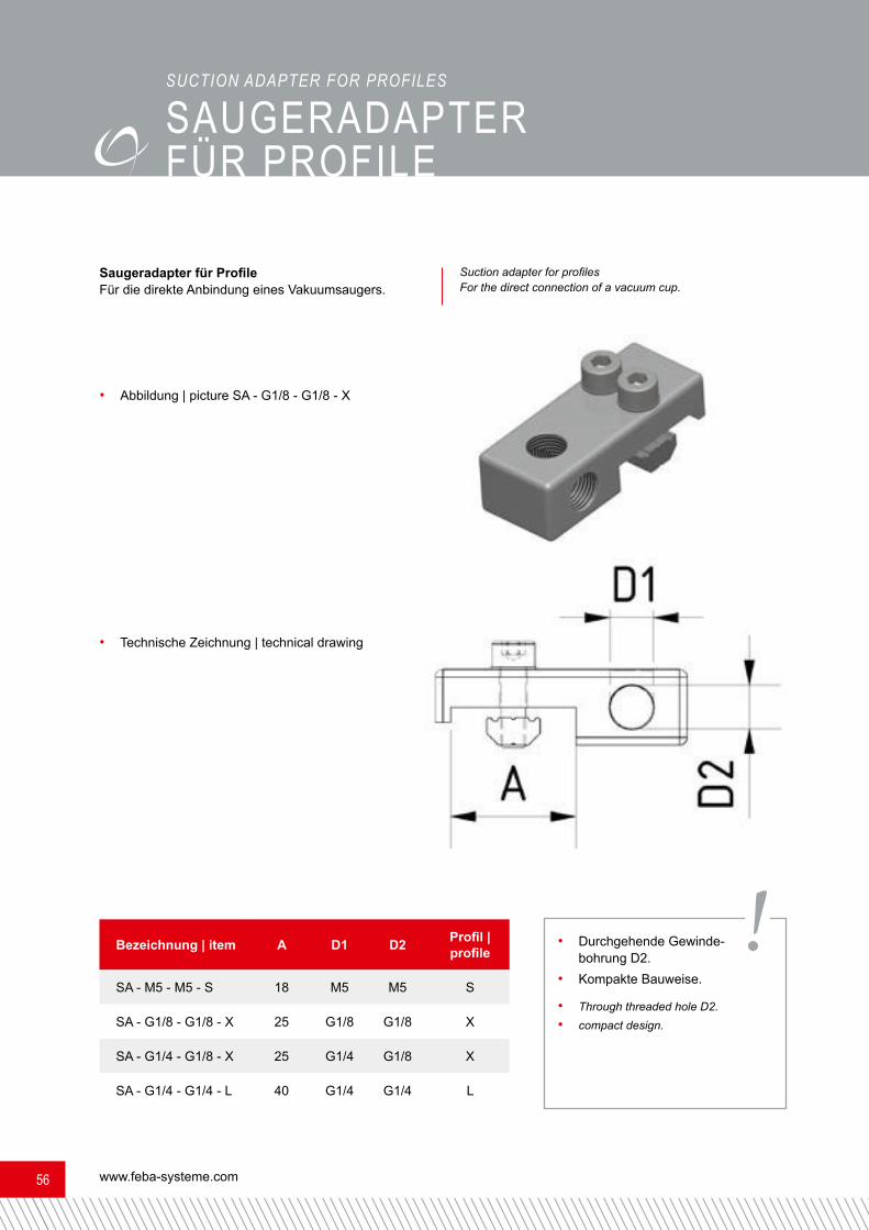
sAUGERADAPTER FÜR PRoFILESUcTION ADAPTER FOR PROFILESSaugeradapter für ProfileFür die direkte Anbindung eines Vakuumsaugers. Suction adapter for profiles For the direct connection of a vacuum cup.
• Technische Zeichnung | technical drawing
• Abbildung | picture SA - G1/8 - G1/8 - X
• Durchgehende Gewinde-bohrung D2.• Kompakte Bauweise.• Through threaded hole D2.• compact design.
Bezeichnung | item A D1 D2 Profil | profileSA - M5 - M5 - S 18 M5 M5 SSA - G1/8 - G1/8 - X 25 G1/8 G1/8 XSA - G1/4 - G1/8 - X 25 G1/4 G1/8 XSA - G1/4 - G1/4 - L 40 G1/4 G1/4 L
!

Maßangaben in mm | Dimensions in mm 5757
sAUGERADAPTER FÜR PRoFILESUcTION ADAPTER FOR PROFILESSaugeradapter für ProfileFür die direkte Anbindung eines Vakuumsaugers. Suction adapter for profiles For the direct connection of a vacuum cup.
• Technische Zeichnung | technical drawing
• Abbildung | picture SAM - G1/8 - G1/8 - X
• Durchgehende Gewindebohrung D2.• Kompakte Bauweise.• Through threaded hole D2.• compact design.
Bezeichnung | item A B C D E Profil | profileSAM-M5-M5-S 30 16 M5 M5 15 SSAM-G1/8-G1/8-X 40 25 G1/8 G1/8 20 XSAM-G1/4-G1/4-X 40 25 G1/4 G1/4 20 X
!

www.feba-systeme.com58
bEwEGLIcHE sAUGERADAPTERBewegliche Saugeradapterfür Faltenbalgsauger und Flachsauger. Gleicht die Differenzbewegung während der Entformung aus.
Bezeichnung | item A B C D HBSA10 - 58 - H10 - M5 - M5 58 10 M5 M5 10BSA10 - 76 - H20 - M5 - M5 76 10 M5 M5 20BSA14 - 80 - H15 - G1/8 - G1/8 80 14 G1/8 G1/8 15BSA14 - 105 - H35 - G1/8 - G1/8 105 14 G1/8 G1/8 35BSA15 - 80 - H15 - G1/8 - G1/8 80 15 G1/8 G1/8 15BSA15 - 105 - H35 - G1/8 - G1/8 105 15 G1/8 G1/8 35BSA20 - 115 - H20 - G1/4 - G1/4 115 20 G1/4 G1/4 20BSA20 - 139 - H40 - G1/4 - G1/4 139 20 G1/4 G1/4 40
• Technische Zeichnung | technical drawing
• Abbildung | picture BSA20 - 115 - H20 - G1/4 - G1/4
• Das Bauteil ist harteloxiert und hat hervor-ragende Gleiteigenschaften. • The component is hard anodized and has excellent gliding properties.
MOVAbLE SUcTION cUP ADAPTERSMovable suction cup adapters for bellow-type suction cups and flat suction caps. Compen-sates the differential movement during the removal from the mould.
!

Maßangaben in mm | Dimensions in mm 5959
bEwEGLIcHE sAUGER- ADAPTER VERDREHGEsIcHERT
Bezeichnung | item A B C D HBSAV10-58-H10-M5-M5 58 10 M5 M5 10BSAV10-76-H20-M5-M5 76 10 M5 M5 20BSAV14-80-H15-G1/8-G1/8 80 14 G1/8 G1/8 15BSAV14-105-H35-G1/8-G1/8 105 14 G1/8 G1/8 35BSAV15-80-H15-G1/8-G1/8 80 15 G1/8 G1/8 15BSAV15-105-H35-G1/8-G1/8 105 15 G1/8 G1/8 35BSAV20-115-H20-G1/4-G1/4 115 20 G1/4 G1/4 20BSAV20-139-H40-G1/4-G1/4 139 20 G1/4 G1/4 40
• Technische Zeichnung | technical drawing
• Abbildung | picture BSAV20 - 115 - H20 - G1/4 - G1/4
MOVAbLE SUcTION ADAPTERS wIThOUT ROTATINGBewegliche Saugeradapter verdrehgesichertfür ovale Faltenbalgsauger und Flachsauger. Gleicht die Differenzbewegung während der Entfor-mung aus. Starrer Kopf. Movable suction adapters without rotating
for oval bellow-type suctions cups and flat suction caps. Com-pensates the differential movement during the removal from the mould. Fixed Head.
• Das Bauteil ist harteloxiert und hat hervor-ragende Gleiteigenschaften. • Weitere bewegliche Saugeradapter verdreh-gesichert auf Anfrage. • The component is hard anodized and has excellent gliding properties.
• Other movable adhesive disc against rotation on request. !

www.feba-systeme.com60
bEw. sAUGERADAPTER VER-DREHGEsIcHERT mIT GEwINDEBewegliche Saugeradapter verdrehgesichert einstellbarFür ovale, runde Faltenbalg- und Flachsauger geeignet. Ideal für die direkte Montage auf einer Grundplatte.Leichte Verstellbarkeit über das Gewinde. Gleicht Differenzbewegungen während der Entformung aus.
Bezeichnung | item A B G1 G2 HBSAVM12 x 1 - 54 - H15 - M5 - M5 54 27 M5 M5 15BSAVM16 x 1 - 85 - H25 - 1/8 - 1/8 82 40 G1/8 G1/8 25BSAVM20,5 x 1 - 123 - H35 - 1/8 - 1/4 123 60 G1/4 G1/8 35
• Technische Zeichnung | technical drawing
• Abbildung | picture BSAVM12 x 1 - 54 - H15 - M5 - M5
• Das Bauteil ist harteloxiert und hat hervor-ragende Gleiteigenschaften. • The component is hard anodized and has excellent gliding properties.
MOVAbLE SUcTION ADPATERS NON-ROTATING ThREADEDMovable suction adpaters non-rotating threadedSuitable for oval and round bellow-type suction cups as well as flat suction cups. Ideal for direct mounting on a base plate.Easy adjustability via the thread. Compensates the differential movements during the removal from the mould.
!

Maßangaben in mm | Dimensions in mm 6161
ist Ihr innovativer Ansprechpartner in Sachen Automatisierungstechnik
der kunststoff- und blechverarbeitenden Industrie.
Wir bieten Lösungen in den Bereichen:
DER RICHTIGE PARTNER FÜR IHRE ANFORDERUNGEN
GREIFERBAU
•Rundsystem (FFLS)
GREIFERBAU
•Rechtecksystem
SONDERGREIFERBAU
• Lasersintertechnik
ANGUSSTRENNUNG
• Schneiden, Stanzen, Ultraschall
VAKUUMTECHNIK
•Vakuumsauger, Vakuumpumpen
Besuchen Sie uns im Internet: w w w . f e b a - s y s t e m e . c o m
Am Bahnhof 15
57392 Schmallenberg
t +49 29 72 / 962 17 11
f +49 29 72 / 962 17 15

www.feba-systeme.com62
• Passende Kompaktzylinder siehe Seite 72 und 73. • For suitable compact cylinders refer to pages 72 and 73.
Saugeradapter für geführte und ungeführte Kurzhubzylinder.
Bezeichnung | item A B C D E FSA - AG3/8 - G1/8 - M8 - 12 42 25 M8 G1/8 G3/8 12SA - AG3/8 - G1/8 - M8 - 22 52 25 M8 G1/8 G3/8 22
• Technische Zeichnung | technical drawing
• Abbildung | picture SA - AG3/8 - G1/8 - M8 - 12Suction cup adapters for guided and unguided short-stroke cylinders.
!
sAUGERADAPTERSUcTION cUP ADAPTERS

Maßangaben in mm | Dimensions in mm 6363
sAUGERADAPTER
SUcTION cUP ADAPTERSSaugeradapter für geführte und ungeführte Kurzhubzylinder.
Bezeichnung | item A B C D E FSA - IG1/4 - G1/8 - M8 - 12 37 25 M8 G1/8 G1/4 12SA - IG1/4 - G1/8 - M8 - 22 47 25 M8 G1/8 G1/4 22
• Technische Zeichnung | technical drawing
• Abbildung | picture SA - IG1/4 - G1/8 - M8 - 22
• Passende Kompaktzylinder siehe Seite 72 und 73. • For suitable compact cylinders refer to pages 72 and 73.
Suction cup adapters for guided and unguided short-stroke cylinders.
!

www.feba-systeme.com64
ZyLINDERADAPTER
cyLINDER ADAPTERSZylinderadapter mit 2 x M5 Innengewinde, 2 x Durchgangsboh-rung 5,5 mm diagonal.
• Technische Zeichnung | technical drawing• Abbildung | picture ZA - ECDQ2B32 - G - D25• Passende Kompaktzylinder siehe Seite 72 und 73. • For suitable compact cylinders refer to pages 72 and 73.
Cylinder adapters with 4 x M5 inside threads for fastening.
!Bezeichnung | item A B C DZA - ECDQ2B32 - G - D20 45 53 20 45ZA - ECDQ2B32 - G - D25 45 53 25 45ZA - ECDQ2B32 - G - D30 45 53 30 45ZA - ECDQ2B40 - G - D25 52 53 25 52ZA - ECDQ2B40 - G - D30 52 53 30 52

Maßangaben in mm | Dimensions in mm 6565
ZyLINDERADAPTER
cyLINDER ADAPTERSZylinderadapter mit 2 x M5 Innengewinde zum Befestigen. Die Anbin-dung des Kurzhubzylinders erfolgt über einen Winkel von 90°.
Bezeichnung | item A B C DZA - ECDQ2B20 - W - 40 - D14 88 40 14 36ZA - ECDQ2B20 - W - 80 - D14 128 80 14 36ZA - ECDQ2B20 - W - 120 - D14 168 120 14 36ZA - ECDQ2B32 - W - 45 - D20 110 45 20 48ZA - ECDQ2B32 - W - 90 - D20 155 90 20 48ZA - ECDQ2B32 - W - 130 - D20 195 130 20 48
• Technische Zeichnung | technical drawing
• Abbildung | picture ZA - ECDQ2B32 - W - 90 - D20
• Passende Kompaktzylinder siehe Seite 72 und 73. • For suitable compact cylinders refer to pages 72 and 73.
Cylinder adapters with 2 x M5 inside threads for fastening. The mounting of the short-stroke cylinder is carried out with an angle of 90°.
!

www.feba-systeme.com66
GREIFZANGENADAPTER
GreifzangenadapterZum Anbinden der Greifzangen kompakt (GZK Serie).
Bezeichnung | item A B C D EGZA20 - 14 35 40 14 M12x1 25GZA20 - 20 35 48 20 M17x1 25GZA25 - 20 50 55 20 M17x1 30
• Technische Zeichnung | technical drawing• Abbildung | picture GZA20 - 20
GRIPPING PLIERS ADAPTERSGripping pliers adapters For connecting the gripping pliers compact (GZK series).
• Passende Greifzangen kompakt siehe Seite 88 bis 91.• Verlängerungsrohr siehe Seite 70. • For suitable gripping pliers compact refer to page 88 to 91.
• Extension pipes refer to page 70. !• Anwendungsbeispiel | usage example

Maßangaben in mm | Dimensions in mm 6767
Bewegliche GreifzangenadapterZum Anbinden der Greifzangen kompakt (GZK Serie).
Bezeichnung | item A B C D EBGZA20 - 20 - 10 35 58,5 20 25 10BGZA20 - 20 - 20 35 68,5 20 25 20
• Technische Zeichnung | technical drawing• Abbildung | picture BGZA20 - 20 - 20
Movable gripping pliers adapters For connecting the gripping pliers compact (GZK series).
• Passende Greifzangen kompakt siehe Seite 88 bis 91.• Gefederte Anbindung an die Greifzangen kompakt (GZK Serie) möglich. • For suitable gripping pliers compact refer to page 88 to 91.
• Spring connection with gripping pliers compact (GZK series) possible. !
bEwEGLIcHE GREIFZANGENADAPTERMOVAbLE GRIPPING PLIERS ADAPTERS
• Anwendungsbeispiel | usage example

www.feba-systeme.com68
• Passende Parallelgreifer siehe Seite 76. • For suitable parallel grippers refer to page 76
Greiferadaptermit Langnuten zum zusätzlichen Justieren direkt am Adapter.
Bezeichnung | item A B C DGA - MHZ2 - 10 - G - D14 24 40 14 24GA - MHZ2 - 20 - G - D16 45 53 16 45GA - MHZ2 - 25 - G - D20 52 55 20 52
• Technische Zeichnung | technical drawing• Abbildung | picture GA - MHZ2 - 20 - G - D16
Gripper adapters with long grooves for an extra adjustment directly on the adapter.
!
GREIFERADAPTER
GRIPPER ADAPTERS

Maßangaben in mm | Dimensions in mm 6969
Haltewinkel GZK20Zum Anbinden der Greifzangen kompakt (GZK20 Serie). Die GZK20 kann stirnseitig und seitlich montiert werden.
Bezeichnung | item A B C D E F GHW - GZK20 - 90 60 45 6 19,8 34 28 18
• Technische Zeichnung | technical drawing
• Abbildung | picture HW-GZK20-90
Holding Bracket GZK20 For connecting the gripping pliers compact (GZK20 series). The GZK20 can be mounted frontally and laterally.
• Material: Aluminium.• Mehrere Anbindungsmöglichkeiten.• Passende Greifzangen siehe Seite 88 bis 91.
• Material: aluminum.• Multiple connectivity options.• For suitable Gripping pliers refer to pages 88 to 91.!
• Anwendungsbeispiel | usage example
HALTEwINKEL GZK20hOLDING bRAckET GZk20

www.feba-systeme.com70
VERLÄNGERUNGsRoHRE
Verlängerungsrohrezum Verlängern von Zentrierbolzen sowie Greifzangen und Greiffinger.
Bezeichnung | item A B CVR14 - 50 - M12 x 1 50 14 M12x1
VR14 - 100 - M12 x 1 100 14 M12x1
VR20 - 50 - M17 x 1 50 20 M17x1
VR20 - 100 - M17 x 1 100 20 M17x1
VR20 - 150 - M17 x 1 150 20 M17x1
• Technische Zeichnung | technical drawing• Abbildung | picture VR20 - 50 - M17 x 1
• Greifzangen (GZ) ab Seite 79.• Greiffinger (GF) ab Seite 110.
• Gripping pliers (GZ) from page 79.• Gripping fingers (GF) from page 110.
Extension pipes used to lengthen centering pins as well as gripping pliers and gripping fingers.
EXTENSION PIPES
!

Maßangaben in mm | Dimensions in mm 7171
mINIATURZyLINDER
MiniaturzylinderZylinder inklusive Magnet zwecks Stellungsabfrage. Innengewinde der Kolbenstange M3.
Bezeichnung | item A B C D HubMZ - CDUJB10 - 10D 29 22 13,5 26,5 10MZ - CDUJB10 - 20D 39 22 13,5 36,5 20MZ - CDUJB10 - 10DM 34 22 13,5 26,5 10MZ - CDUJB10 - 20DM 44 22 13,5 36,5 20MZ - CDUJB20 - 10D 34 36 25 29,5 10MZ - CDUJB20 - 20D 44 36 25 39,5 20MZ - CDUJB20 - 10DM 38 36 25 29,5 10MZ - CDUJB20 - 20DM 48 36 25 39,5 20
• Abbildung | picture MZ - CDUJB10 - 10D • Technische Zeichnung, in Ruhestellung• Technical drawing, in inoperative position
• Weitere Miniaturzylinder auf Anfrage.• Zylindersensor siehe Seite 123. • Further miniature cylinders on demand.
• For cylinder sensors refer to page 123.
Miniature cylinders Cylinder incl. magnet for the purpose of position query. Inside thread of the piston rod M3.
MINIATURE cyLINDERS
!
• Ø Befestigungsbohrung 3,3 mm bei 10 mm Kolben• Ø Befestigungsbohrung 5,3 mm bei 20 mm Kolben • Ø mounting hole 3.3 mm for 10 mm piston
• Ø mounting hole 5.3 mm for 20 mm piston

www.feba-systeme.com72
KomPAKTZyLINDER
KompaktzylinderZylinder inklusive Magnet zwecks Stellungsabfrage. Innengewinde der Kolbenstange M8.
• Technische Zeichnung, in Ruhestellung• Technical drawing, in inoperative position• Abbildung | picture KZ - ECDQ2B32 - 20D
Bezeichnung | item A B C Hub | strokeKZ - ECDQ2B20 - 10D 46 36 47 10KZ - ECDQ2B20 - 20D 56 36 47 10KZ - ECDQ2B20 - 25D 61 36 47 10KZ - ECDQ2B20 - 40D 76 36 47 10 KZ - ECDQ2B32 - 10D 50 45 45 10KZ - ECDQ2B32 - 20D 60 45 45 20KZ - ECDQ2B32 - 25D 65 45 45 25KZ - ECDQ2B32 - 40D 80 45 45 40KZ - ECDQ2B40 - 10D 56,5 52 52 10KZ - ECDQ2B40 - 20D 66,5 52 52 20KZ - ECDQ2B40 - 25D 71,5 52 52 25KZ - ECDQ2B40 - 40D 86,5 52 52 40
• Weitere Kompaktzylinder auf Anfrage.• Zylindersensor siehe Seite 123.• Zylinderadapter siehe Seite 64 und 65.• Saugeradapter ab Seite 62 und 63.• Anschlussgewinde G1/8.
• Further compact cylinders on demand.• For cylinder sensors refer to page 123.• For cylinder adapters refer to page 64 and 65.• Suction cup adapters from page 62 and 63.• connection thread G1/8
cOMPAcT cyLINDERSCompact cylinders Cylinder incl. magnet for the purpose of position query. Inside thread of the piston rod M8.
!
Maßangaben in mm | Dimensions in mm 7373
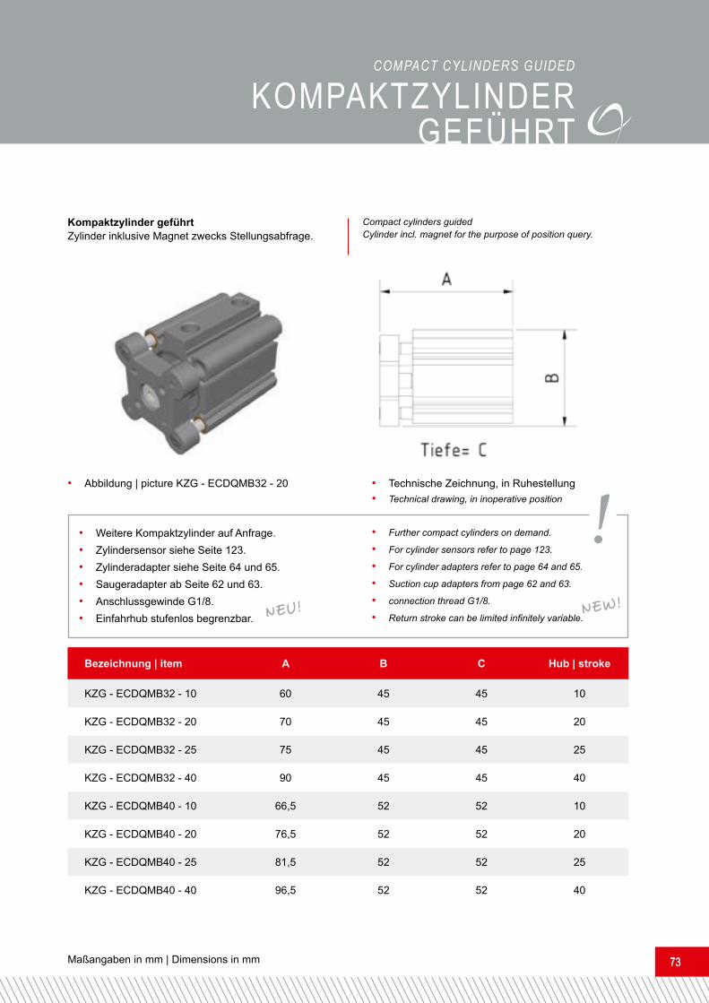
Kompaktzylinder geführtZylinder inklusive Magnet zwecks Stellungsabfrage.
• Technische Zeichnung, in Ruhestellung• Technical drawing, in inoperative position• Abbildung | picture KZG - ECDQMB32 - 20
KomPAKTZyLINDERGEFÜHRT
• Weitere Kompaktzylinder auf Anfrage.• Zylindersensor siehe Seite 123.• Zylinderadapter siehe Seite 64 und 65.• Saugeradapter ab Seite 62 und 63.• Anschlussgewinde G1/8.• Einfahrhub stufenlos begrenzbar.
• Further compact cylinders on demand.• For cylinder sensors refer to page 123.• For cylinder adapters refer to page 64 and 65.
• Suction cup adapters from page 62 and 63.• connection thread G1/8.• Return stroke can be limited infinitely variable.Bezeichnung | item A B C Hub | strokeKZG - ECDQMB32 - 10 60 45 45 10KZG - ECDQMB32 - 20 70 45 45 20KZG - ECDQMB32 - 25 75 45 45 25KZG - ECDQMB32 - 40 90 45 45 40KZG - ECDQMB40 - 10 66,5 52 52 10KZG - ECDQMB40 - 20 76,5 52 52 20KZG - ECDQMB40 - 25 81,5 52 52 25KZG - ECDQMB40 - 40 96,5 52 52 40
cOMPAcT cyLINDERS GUIDEDCompact cylinders guided Cylinder incl. magnet for the purpose of position query.
!NEW!NEU!
www.feba-systeme.com74
KomPAKTscHLITTENGEFÜHRT
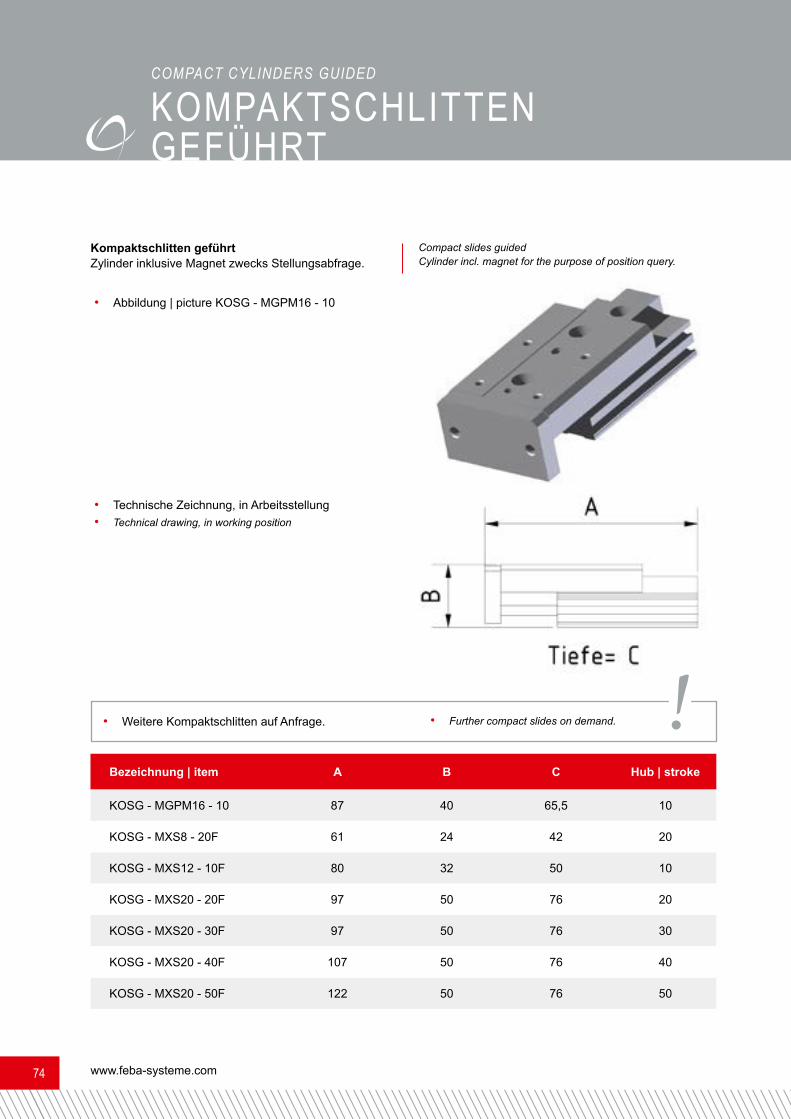
Kompaktschlitten geführtZylinder inklusive Magnet zwecks Stellungsabfrage.
• Technische Zeichnung, in Arbeitsstellung• Technical drawing, in working position
• Abbildung | picture KOSG - MGPM16 - 10
Bezeichnung | item A B C Hub | strokeKOSG - MGPM16 - 10 87 40 65,5 10KOSG - MXS8 - 20F 61 24 42 20KOSG - MXS12 - 10F 80 32 50 10KOSG - MXS20 - 20F 97 50 76 20KOSG - MXS20 - 30F 97 50 76 30KOSG - MXS20 - 40F 107 50 76 40KOSG - MXS20 - 50F 122 50 76 50
• Weitere Kompaktschlitten auf Anfrage. • Further compact slides on demand.
Compact slides guided Cylinder incl. magnet for the purpose of position query.
!
cOMPAcT cyLINDERS GUIDED

Maßangaben in mm | Dimensions in mm 7575
Miniaturzylinder geführtZylinder inklusive Magnet zwecks Stellungsabfrage.
• Technische Zeichnung, in Ruhestellung• Technical drawing, in inoperative position
• Abbildung | picture MZ - MGJ10 - 10
mINIATURZyLINDER GEFÜHRT
Bezeichnung | item A B C Hub | strokeMZ - MGJ10 - 10 35 17 33 10MZ - MGJ10 - 20 45 17 33 20
• Weitere Miniaturzylinder mit Führung sowie Kompaktzylinder mit Führung auf Anfrage.• Zylindersensor siehe Seite 123. • Further miniature cylinders with guidance system as well as compact cylinders with guidance system on demand.
• For cylinder sensors refer to page 123.
Miniature cylinders, guided Cylinder incl. magnet for the purpose of position query.
!
MINIATURE cyLINDERS GUIDED

www.feba-systeme.com76
PARALLELGREIFER
ParallelgreiferZylinder inklusive Magnet zwecks Stellungsabfrage.• Abbildung | picture PG - MHZ2 - 20D
Bezeichnung | item A B C Öffnungsweg | opening channelPG - MHZ2 - 10D 57 29 16,4 4PG - MHZ2 - 20D 84,8 50 27,6 10PG - MHZ2 - 25D 102,7 63 33,6 14
• Passende gummierte Backen aus Polyamid siehe Seite 118.• Parallelgreiferadapter siehe Seite 68.• Zylindersensor siehe Seite 123.• Weitere Parallelgreifer auf Anfrage.
• For suitable rubberized jaws made of polyamide refer to pages 118.• For parallel gripper adapters refer to page 68.• For cylinder sensors refer to page 123.• Further parallel grippers on demand.
PARALLEL GRIPPERSParallel grippers Cylinder incl. magnet for the purpose of position query.
• Technische Zeichnung, in Ruhestellung• Technical drawing, in inoperative position
!
Maßangaben in mm | Dimensions in mm 7777
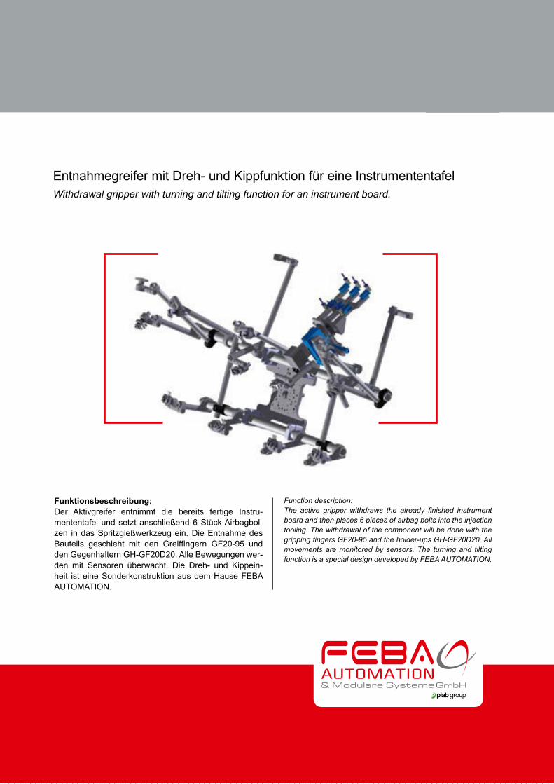
Entnahmegreifer mit Dreh- und Kippfunktion für eine InstrumententafelWithdrawal gripper with turning and tilting function for an instrument board.
Funktionsbeschreibung:Der Aktivgreifer entnimmt die bereits fertige Instru-mententafel und setzt anschließend 6 Stück Airbagbol-zen in das Spritzgießwerkzeug ein. Die Entnahme des Bauteils geschieht mit den Greiffingern GF20-95 und den Gegenhaltern GH-GF20D20. Alle Bewegungen wer-den mit Sensoren überwacht. Die Dreh- und Kippein-heit ist eine Sonderkonstruktion aus dem Hause FEBA AUTOMATION.
Function description:The active gripper withdraws the already finished instrument board and then places 6 pieces of airbag bolts into the injection tooling. The withdrawal of the component will be done with the gripping fingers GF20-95 and the holder-ups GH-GF20D20. All movements are monitored by sensors. The turning and tilting function is a special design developed by FEBA AUTOMATION.
www.feba-systeme.com78
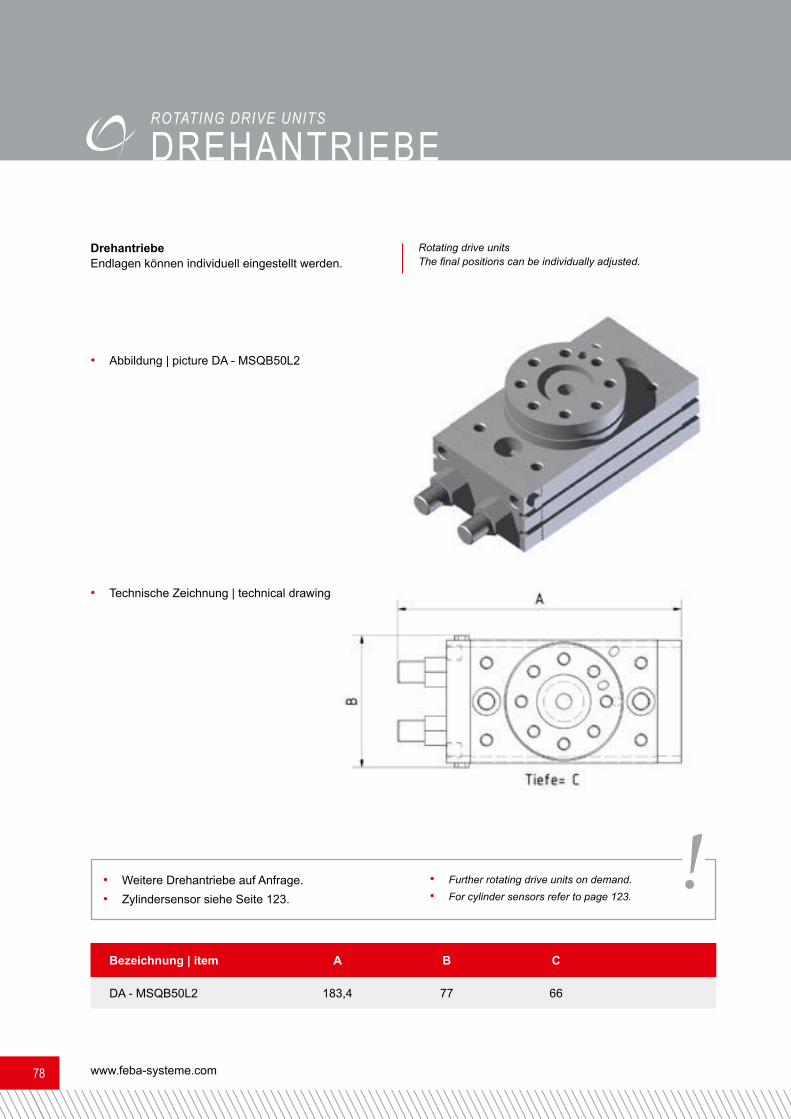
DREHANTRIEbE
ROTATING DRIVE UNITSDrehantriebeEndlagen können individuell eingestellt werden.
• Technische Zeichnung | technical drawing
• Abbildung | picture DA - MSQB50L2
Bezeichnung | item A B CDA - MSQB50L2 183,4 77 66• Weitere Drehantriebe auf Anfrage.• Zylindersensor siehe Seite 123. • Further rotating drive units on demand.
• For cylinder sensors refer to page 123.
Rotating drive units The final positions can be individually adjusted.
!
Maßangaben in mm | Dimensions in mm 7979
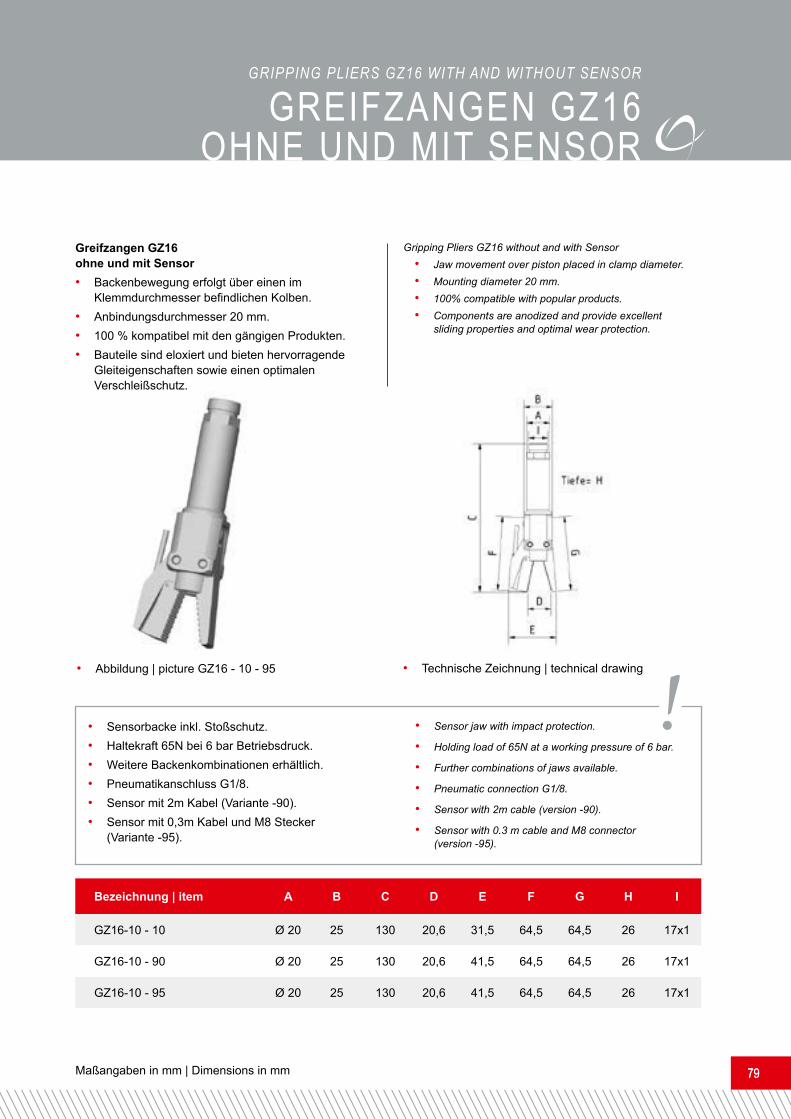
Greifzangen GZ16 ohne und mit Sensor• Backenbewegung erfolgt über einen im
Klemmdurchmesser befindlichen Kolben.• Anbindungsdurchmesser 20 mm.• 100 % kompatibel mit den gängigen Produkten.• Bauteile sind eloxiert und bieten hervorragende Gleiteigenschaften sowie einen optimalen Verschleißschutz.
• Technische Zeichnung | technical drawing• Abbildung | picture GZ16 - 10 - 95• Sensorbacke inkl. Stoßschutz.• Haltekraft 65N bei 6 bar Betriebsdruck.• Weitere Backenkombinationen erhältlich.• Pneumatikanschluss G1/8.• Sensor mit 2m Kabel (Variante -90).• Sensor mit 0,3m Kabel und M8 Stecker (Variante -95).
• Sensor jaw with impact protection.• Holding load of 65N at a working pressure of 6 bar.• Further combinations of jaws available.• Pneumatic connection G1/8.• Sensor with 2m cable (version -90).• Sensor with 0.3 m cable and M8 connector (version -95).Bezeichnung | item A B C D E F G H IGZ16-10 - 10 Ø 20 25 130 20,6 31,5 64,5 64,5 26 17x1GZ16-10 - 90 Ø 20 25 130 20,6 41,5 64,5 64,5 26 17x1GZ16-10 - 95 Ø 20 25 130 20,6 41,5 64,5 64,5 26 17x1
Gripping Pliers GZ16 without and with Sensor• Jaw movement over piston placed in clamp diameter.• Mounting diameter 20 mm.• 100% compatible with popular products. • Components are anodized and provide excellent sliding properties and optimal wear protection.
!
GREIFZANGEN GZ16 oHNE UND mIT sENsoRGRIPPING PLIERS GZ16 wITh AND wIThOUT SENSOR

www.feba-systeme.com80
Bezeichnung | item A B C D E F G HGZ12 - 00 - 00 10 25 80 22 31 55 55 15GZ12 - 10 - 10 10 25 80 22 31 55 55 15GZ12 - 11 - 11 10 25 80 25 33,5 60 60 15GZ12 - 12 - 12 10 25 80 22 31 55 55 18,5GZ12 - 40 - 40 10 25 80 22 31 55 55 15GZ12 - 50 - 50 10 25 80 22 31 55 55 15GZ12 - 60 - 60 10 25 80 22 31 55 55 15GZ12 - 65 - 65 10 25 80 22 35,5 55 55 15
GREIFZANGEN GZ12GRIPPING PLIERS GZ12
• Haltekraft 31N bei 6 bar Betriebsdruck.• Pneumatikanschluss M5.
• Holding load of 31N at a working pressure of 6 bar.• Pneumatic connection M5. !
Greifzangen GZ12 ohne Sensor• Backenbewegung über zwei Kolben.• Keine innenliegende Rückholfeder, daher kein Kraftverlust.• Große Auswahl an Backen, die untereinander kombinierbar sind.• Anbindungsdurchmesser D = 10 mm oder M10 x 1• 100% kompatibel mit den gängigen Produkten.• Alle Bauteile sind eloxiert und bieten hervorra-gende Gleiteigenschaften sowie einen optimalen Verschleißschutz.• Einfacher Backenwechsel durch Lösen der Sicherungskappen.
Gripping pliers GZ12 without sensor• Movement of the jaws by two pistons.• No inside recuperating spring, therefore no loss of power.• A wide range of jaws which can be combined among each other.• Mounting diameter D = 10 mm or M10 x 1• 100 % compatible with common products.• All components are anodized and offer excellent gliding properties as well as the best possible wearing protection.• Easy jaw change by loosening of the safety caps.NEW!NEU!

Maßangaben in mm | Dimensions in mm 8181
• Technische Zeichnung | technical drawing
• Abbildung GZ12 - 00 - 00 mit Standardbacken glatt• picture GZ12 - 00 - 00 with standard jaws plain GZ12 - 10 - 10
• mit Standardbacken• with standard jawsGZ12 - 11 - 11• mit Standardbacken, lange Version• with standard jaws, long versionGZ12 - 12 - 12• mit Standardbacken, breite Version• with standard jaws, bride versionGZ12 - 40 - 40• mit Konturbacken• with shaped jawsGZ12 - 50 - 50• mit Sägezahnbacken• with saw tooth jaws
GREIFZANGEN GZ12GRIPPING PLIERS GZ12

www.feba-systeme.com82
GREIFZANGEN GZ12 mIT sENsoR
• Sensorbacke inkl. Stoßschutz.• Haltekraft 31N bei 6 bar Betriebsdruck.• Sensor siehe Seite 123.• Pneumatikanschluss M5.
• Sensor jaw with impact protection• Holding load of 31N at a working pressure of 6 bar.• For sensors refer to page 123.• Pneumatic connection M5.
GRIPPING PLIERS GZ12 wITh SENSOR
!
Bezeichnung | item A B C D E F G HGZ12-10-90 10 25 80 20 39 57 57 15GZ12-10-95 10 25 80 20 39 57 57 15GZ12-40-90 10 25 80 20 39 57 57 15GZ12-40-95 10 25 80 20 39 57 57 15GZ12-50-90 10 25 85 20 39 62 62 15GZ12-50-95 10 25 85 20 39 62 62 15
Greifzangen GZ12 ohne Sensor• Backenbewegung über zwei Kolben.• Keine innenliegende Rückholfeder, daher kein Kraftverlust.• Große Auswahl an Backen, die untereinander kombinierbar sind.• Anbindungsdurchmesser D = 10 mm oder M10 x 1• 100% kompatibel mit den gängigen Produkten.• Alle Bauteile sind eloxiert und bieten hervorra-gende Gleiteigenschaften sowie einen optimalen Verschleißschutz.• Einfacher Backenwechsel durch Lösen der Sicherungskappen.
Gripping pliers GZ12 without sensor• Movement of the jaws by two pistons.• No inside recuperating spring, therefore no loss of power.• A wide range of jaws which can be combined among each other.• Mounting diameter D = 10 mm or M10 x 1• 100 % compatible with common products.• All components are anodized and offer excellent gliding properties as well as the best possible wearing protection.• Easy jaw change by loosening of the safety caps.NEW!NEU!

Maßangaben in mm | Dimensions in mm 8383
• Technische Zeichnung | technical drawing
• Abbildung GZ12 - 10 - 90 mit Sensorbacke inkl. Sensor mit 2 m Kabel• picture GZ12 - 20 - 90 with sensor jaws incl. sensor with 2 m cable
GZ12 - 55 - 90• mit Sägezahn- und Sensorbacke inkl. Sensor mit 2m Kabel• with saw tooth- and sensor jaws incl. sensor with 2m cable GZ12 - 55 - 95• mit Sägezahn- und Sensorbacke inkl. Sensor mit 0,3m Kabel und M8 Stecker• with saw tooth- and sensor jaws incl. sen-sor with 0,3m cable and M8 connector
GZ12 - 10 - 95• mit Sensorbacke inkl. Sensor mit 0,3m Kabel und M8 Stecker • with sensor jaw incl. sensor with 0,3m cable and M8 connector
GZ12 - 40 - 90• mit Kontur- und Sensorbacke inkl. Sensor mit 2m Kabel• with shaped and sensor jaw incl. sensor with 2m cableGZ12 - 40 - 95• mit Kontur- und Sensorbacke inkl. Sensor mit 0,3m Kabel und M8 Stecker• with shaped and sensor jaw incl. sensor with 0,3m cable and M8 connector
GREIFZANGEN GZ12 mIT sENsoRGRIPPING PLIERS GZ12 wITh SENSOR
www.feba-systeme.com84
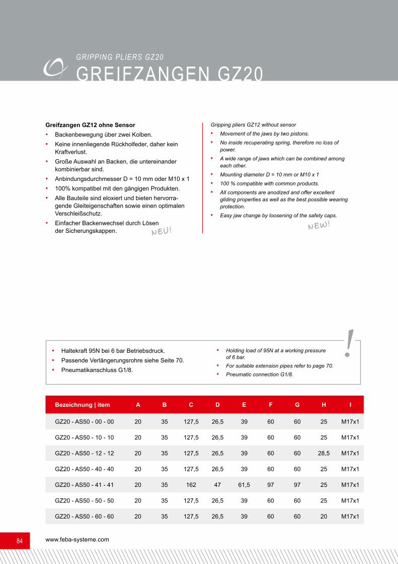
• Haltekraft 95N bei 6 bar Betriebsdruck.• Passende Verlängerungsrohre siehe Seite 70.• Pneumatikanschluss G1/8.
• Holding load of 95N at a working pressure of 6 bar.• For suitable extension pipes refer to page 70.• Pneumatic connection G1/8.
GREIFZANGEN GZ20GRIPPING PLIERS GZ20
!
Bezeichnung | item A B C D E F G H IGZ20 - AS50 - 00 - 00 20 35 127,5 26,5 39 60 60 25 M17x1GZ20 - AS50 - 10 - 10 20 35 127,5 26,5 39 60 60 25 M17x1GZ20 - AS50 - 12 - 12 20 35 127,5 26,5 39 60 60 28,5 M17x1GZ20 - AS50 - 40 - 40 20 35 127,5 26,5 39 60 60 25 M17x1GZ20 - AS50 - 41 - 41 20 35 162 47 61,5 97 97 25 M17x1GZ20 - AS50 - 50 - 50 20 35 127,5 26,5 39 60 60 25 M17x1GZ20 - AS50 - 60 - 60 20 35 127,5 26,5 39 60 60 20 M17x1
Greifzangen GZ12 ohne Sensor• Backenbewegung über zwei Kolben.• Keine innenliegende Rückholfeder, daher kein Kraftverlust.• Große Auswahl an Backen, die untereinander kombinierbar sind.• Anbindungsdurchmesser D = 10 mm oder M10 x 1• 100% kompatibel mit den gängigen Produkten.• Alle Bauteile sind eloxiert und bieten hervorra-gende Gleiteigenschaften sowie einen optimalen Verschleißschutz.• Einfacher Backenwechsel durch Lösen der Sicherungskappen.
Gripping pliers GZ12 without sensor• Movement of the jaws by two pistons.• No inside recuperating spring, therefore no loss of power.• A wide range of jaws which can be combined among each other.• Mounting diameter D = 10 mm or M10 x 1• 100 % compatible with common products.• All components are anodized and offer excellent gliding properties as well as the best possible wearing protection.• Easy jaw change by loosening of the safety caps.NEW!NEU!

Maßangaben in mm | Dimensions in mm 8585
GREIFZANGEN GZ20GRIPPING PLIERS GZ20
• Technische Zeichnung | technical drawing
• Abbildung GZ20 - AS50 - 00 - 00 mit Standardbacken glatt• picture GZ20 - AS50 - 00 - 00 with standard jaws plain GZ20 - AS50 - 10 - 10
• mit Standardbacken• with standards jawsGZ20 - AS50 - 12 - 12• mit Standardbacken, breite Version• with standard jaws, bride versionGZ20 - AS50 - 40 - 40• mit Konturbacken• with shaped jawsGZ20 - AS50 - 41 - 41• mit Konturbacken lang glatt / Schließweg einstellbar• with shaped jaws long plain / clamping mode adjustableGZ20 - AS50 - 50 - 50• mit Sägezahnbacken• with saw tooth jaws GZ20 - AS50 - 60 - 60• mit Standardbacken, gummiert• with standards jaws, rubberized

www.feba-systeme.com86
GREIFZANGEN GZ20 mIT sENsoRGRIPPING PLIERS GZ20 wITh SENSOR
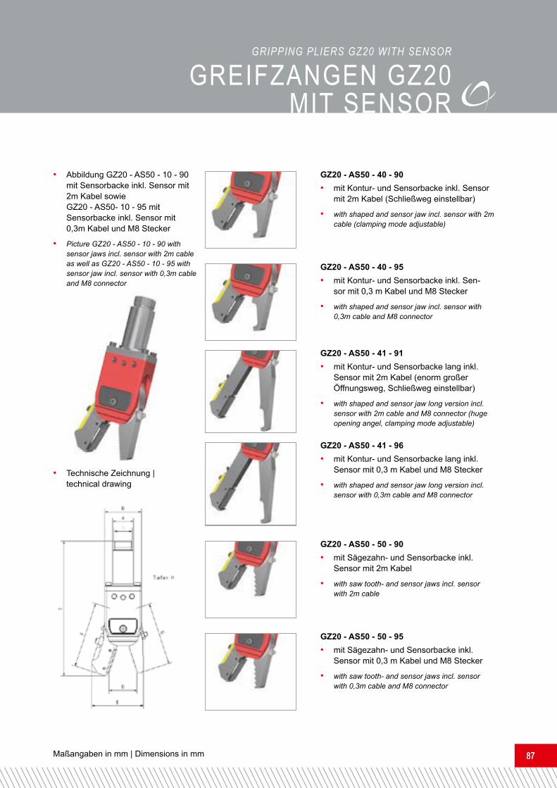
Bezeichnung | item A B C D E F G H IGZ20 - AS50 - 10 - 90 20 35 130 26,5 50 63 60 25 M17x1GZ20 - AS50 - 10 - 95 20 35 130 26,5 50 63 60 25 M17x1GZ20 - AS50 - 40 - 90 20 35 130 26,5 50 63 60 25 M17x1GZ20 - AS50 - 40 - 95 20 35 130 26,5 50 63 60 25 M17x1GZ20 - AS50 - 41 - 91 20 35 162 47 73 100 97 25 M17x1GZ20 - AS50 - 41 - 96 20 35 162 47 73 100 97 25 M17x1GZ20 - AS50 - 50 - 90 20 35 130 26,5 50 63 60 25 M17x1GZ20 - AS50 - 50 - 95 20 35 130 26,5 50 63 60 25 M17x1
Greifzangen GZ20 mit Sensor• Backenbewegung über zwei Kolben.• Keine innenliegende Rückholfeder, daher kein Kraftverlust.• Große Auswahl an Backen, die untereinander kombinierbar sind.• Anbindungsdurchmesser D = 20 mm oder M17 x 1.• 100% kompatibel mit den gängigen Produkten.• Alle Bauteile sind eloxiert und bieten hervor- ragende Gleiteigenschaften sowie einen optimalen Verschleißschutz.• Sensor mit 2m Kabel (Variante -90 / -91).• Sensor mit 0,3m Kabel und M8 Stecker (Variante -95).• Einfacher Backenwechsel durch Lösen der Sicherungskappen.
Gripping pliers GZ20 with sensor• Movement of the jaws by two pistons.• No inside recuperating spring, therefore no loss of power.• A wide range of jaws which can be combined among each other.• Mounting diameter D = 20 mm or M17 x 1• 100 % compatible with common products.• All components are anodized and offer excellent gliding properties as well as the best possible wearing protection.• Sensor with 2m cable (version -90 / -91).• Sensor with 0.3 m cable and M8 connector (version -95).• Easy jaw change by loosening of the safety caps.
• Sensorbacke inkl. Stoßschutz.• Haltekraft 95N bei 6 bar Betriebsdruck.• Passende Verlängerungsrohre siehe Seite 70.• Pneumatikanschluss G1/8.
• Sensor jaw with impact protection.• Holding load of 95N at a working pressure of 6 bar.• For suitable extension pipes refer to page 70.• Pneumatic connection G1/8.
!
NEW!NEU!
Maßangaben in mm | Dimensions in mm 8787
• Technische Zeichnung | technical drawing
• Abbildung GZ20 - AS50 - 10 - 90 mit Sensorbacke inkl. Sensor mit 2m Kabel sowie GZ20 - AS50- 10 - 95 mit Sensorbacke inkl. Sensor mit 0,3m Kabel und M8 Stecker• Picture GZ20 - AS50 - 10 - 90 with sensor jaws incl. sensor with 2m cable as well as GZ20 - AS50 - 10 - 95 with sensor jaw incl. sensor with 0,3m cable and M8 connector
GZ20 - AS50 - 50 - 90• mit Sägezahn- und Sensorbacke inkl. Sensor mit 2m Kabel• with saw tooth- and sensor jaws incl. sensor with 2m cableGZ20 - AS50 - 50 - 95• mit Sägezahn- und Sensorbacke inkl. Sensor mit 0,3 m Kabel und M8 Stecker• with saw tooth- and sensor jaws incl. sensor with 0,3m cable and M8 connector
GZ20 - AS50 - 40 - 90• mit Kontur- und Sensorbacke inkl. Sensor mit 2m Kabel (Schließweg einstellbar)• with shaped and sensor jaw incl. sensor with 2m cable (clamping mode adjustable)GZ20 - AS50 - 40 - 95• mit Kontur- und Sensorbacke inkl. Sen-sor mit 0,3 m Kabel und M8 Stecker • with shaped and sensor jaw incl. sensor with 0,3m cable and M8 connectorGZ20 - AS50 - 41 - 91• mit Kontur- und Sensorbacke lang inkl. Sensor mit 2m Kabel (enorm großer Öffnungsweg, Schließweg einstellbar)• with shaped and sensor jaw long version incl. sensor with 2m cable and M8 connector (huge opening angel, clamping mode adjustable)GZ20 - AS50 - 41 - 96• mit Kontur- und Sensorbacke lang inkl. Sensor mit 0,3 m Kabel und M8 Stecker • with shaped and sensor jaw long version incl. sensor with 0,3m cable and M8 connector
GREIFZANGEN GZ20 mIT sENsoRGRIPPING PLIERS GZ20 wITh SENSOR

www.feba-systeme.com88
GREIFZANGEN KomPAKT GZK20 GRIPPING PLIERS cOMPAcT GZk20
Bezeichnung | item A B C D E F G H IGZK20 - 00 - 00 17,5 35 78 26 38 60 60 25 27,5GZK20 - 10 - 10 17,5 35 78 26 38 60 60 25 27,5GZK20 - 12 - 12 17,5 35 78 26 38 60 60 25 27,5GZK20 - 30 - 30 17,5 35 78 27 38 60 60 25 27,5GZK20 - 41 - 41 17,5 35 113 46 59 97 97 25 27,5GZK20 - 50 - 50 17,5 35 79 27 38 60 60 25 27,5GZK20 - 60 - 60 17,5 35 78 26 38 60 60 25 27,5
Greifzangen kompakt GZK20 ohne Sensor• Backenbewegung über zwei Kolben.• Keine innenliegende Rückholfeder, daher kein Kraftverlust.• Große Auswahl an Backen, die untereinander kombinierbar sind.• Alle Bauteile sind eloxiert und bieten hervor-ragende Gleiteigenschaften sowie einen optimalen Verschleißschutz.• Kann direkt montiert werden.• Einfacher Backenwechsel durch Lösen der Sicherungskappen.
• Haltekraft 95N bei 6 bar Betriebsdruck.• Passende Greifzangenadapter siehe Seite 66.• Pneumatikanschluss G1/8 (stirnseitig und seitlich möglich). • Holding load of 95N at a working pressure of 6 bar.
• For suitable gripping pliers adapters refer to page 66.• Pneumatic connection G1/8 (frontally and laterally possible).
Gripping pliers compact GZK20 without sensor• Movement of the jaws by two pistons.• No inside recuperating spring, therefore no loss of power.• A wide range of jaws which can be combined among each other.• All components are anodized and offer excellent gliding properties as well as the best possible wearing protection.• Can be fixed directly.
• Easy jaw change by loosening of the safety caps.
!
NEW!NEU!

Maßangaben in mm | Dimensions in mm 8989
GREIFZANGEN KomPAKT GZK20GRIPPING PLIERS cOMPAcT GZk20GZK20 - 10 - 10• mit Standardbacken• with standards jawsGZK20 - 12 - 12• mit Standardbacken, breite Version• with standard jaws, bride versionGZK20 - 40 - 40• mit Konturbacken• with shaped jawsGZK20 - 41 - 41• mit Konturbacken lang glatt / Schließweg einstellbar• with shaped jaws long plain / clamping mode adjustableGZK20 - 50 - 50• mit Sägezahnbacken• with saw tooth jaws
• Technische Zeichnung | technical drawing
• Abbildung GZK20 - 00 - 00 mit Standardbacken glatt• picture GZK20 - 00 - 00 with standard jaws plain
GZK20 - 60 - 60• mit Standardbacken, gummiert• with standards jaws, rubberized

www.feba-systeme.com90
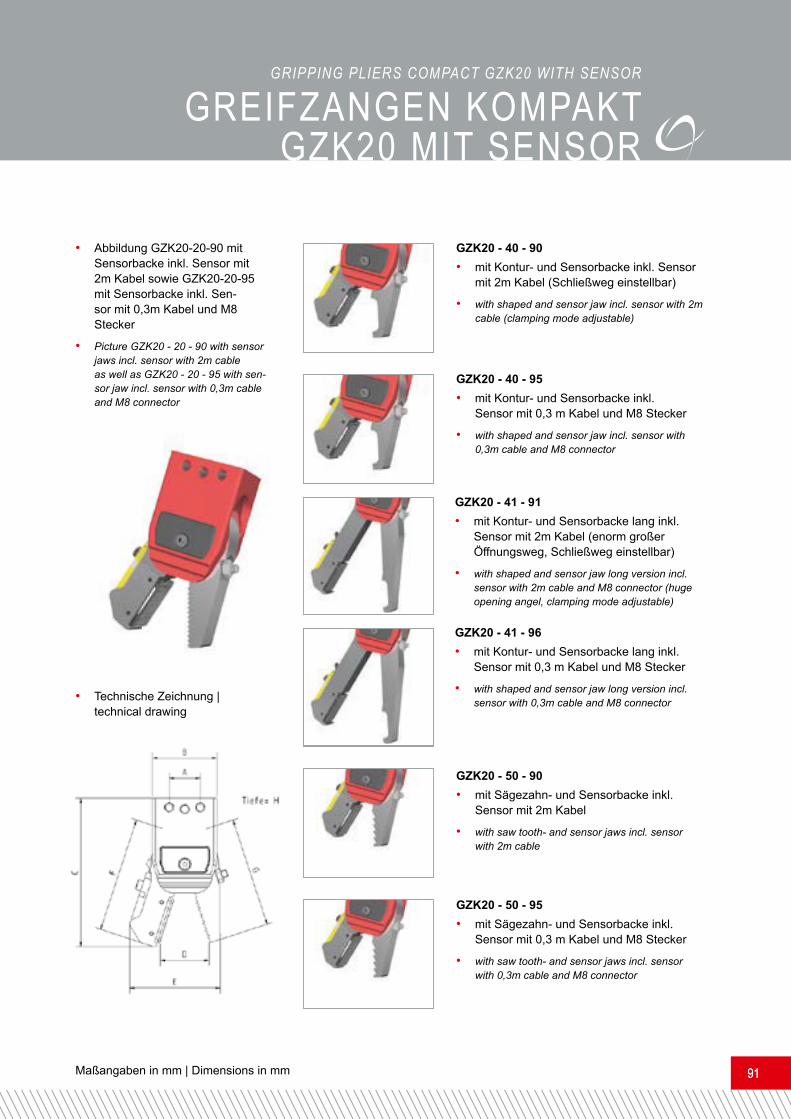
GREIFZANGEN KomPAKT GZK20 mIT sENsoRGRIPPING PLIERS cOMPAcT GZk20 wITh SENSORGreifzangen kompakt GZK20 mit Sensor• Backenbewegung über zwei Kolben.• Keine innenliegende Rückholfeder, daher kein Kraftverlust.• Große Auswahl an Backen, die untereinander kombinierbar sind.• Alle Bauteile sind eloxiert und bieten hervor- ragende Gleiteigenschaften sowie einen optimalen Verschleißschutz.• Sensor mit 2m Kabel (Variante -90 / -91).• Sensor mit 0,3m Kabel und M8 Stecker (Variante -95).• Kann direkt montiert werden.• Einfacher Backenwechsel durch Lösen der Sicherungskappen.
Gripping pliers compact GZK20 with sensor • Movement of the jaws by two pistons.• No inside recuperating spring, therefore no loss of power.• A wide range of jaws which can be combined among each other.• All components are anodized and offer excellent gliding properties as well as the best possible wearing protection.• Sensor with 2m cable (version -90 / -91).• Sensor with 0.3 m cable and M8 connector (version -95).• Can be fixed directly.
• Easy jaw change by loosening of the safety caps.
• Sensorbacke inkl. Stoßschutz• Haltekraft 95N bei 6 bar Betriebsdruck.• Passende Greifzangenadapter siehe Seite 66.• Pneumatikanschluss G1/8 (stirnseitig und seit-lich möglich).
• Sensor jaw with impact protection.• Holding load of 95N at a working pressure of 6 bar.• For suitable gripping pliers adapters refer to page 66.• Pneumatic connection G1/8 (frontally and laterally possible).
!
Bezeichnung | item A B C D E F G H IGZK20 - 20 - 90 17,5 35 78 24 48 60 60 25 27,5GZK20 - 20 - 95 17,5 35 78 24 48 60 60 25 27,5GZK20 - 41 - 91 17,5 35 118 44,5 69 101,5 97 25 27,5GZK20 - 41 - 96 17,5 35 118 44,5 69 101,5 97 25 27,5GZK20 - 40 - 90 17,5 35 78 24 48 60 60 25 27,5GZK20 - 40 - 95 17,5 35 78 24 48 60 60 25 27,5GZK20 - 50 - 90 17,5 35 78 24 48 60 60 25 27,5GZK20 - 50 - 95 17,5 35 78 24 48 60 60 25 27,5
NEW!NEU!
Maßangaben in mm | Dimensions in mm 9191
• Technische Zeichnung | technical drawing
• Abbildung GZK20-20-90 mit Sensorbacke inkl. Sensor mit 2m Kabel sowie GZK20-20-95 mit Sensorbacke inkl. Sen-sor mit 0,3m Kabel und M8 Stecker • Picture GZK20 - 20 - 90 with sensor jaws incl. sensor with 2m cable as well as GZK20 - 20 - 95 with sen-sor jaw incl. sensor with 0,3m cable and M8 connector
GZK20 - 50 - 90• mit Sägezahn- und Sensorbacke inkl. Sensor mit 2m Kabel• with saw tooth- and sensor jaws incl. sensor with 2m cableGZK20 - 50 - 95• mit Sägezahn- und Sensorbacke inkl. Sensor mit 0,3 m Kabel und M8 Stecker • with saw tooth- and sensor jaws incl. sensor with 0,3m cable and M8 connector
GZK20 - 40 - 90• mit Kontur- und Sensorbacke inkl. Sensor mit 2m Kabel (Schließweg einstellbar)• with shaped and sensor jaw incl. sensor with 2m cable (clamping mode adjustable)GZK20 - 40 - 95• mit Kontur- und Sensorbacke inkl. Sensor mit 0,3 m Kabel und M8 Stecker • with shaped and sensor jaw incl. sensor with 0,3m cable and M8 connectorGZK20 - 41 - 91• mit Kontur- und Sensorbacke lang inkl. Sensor mit 2m Kabel (enorm großer Öffnungsweg, Schließweg einstellbar)• with shaped and sensor jaw long version incl. sensor with 2m cable and M8 connector (huge opening angel, clamping mode adjustable)GZK20 - 41 - 96• mit Kontur- und Sensorbacke lang inkl. Sensor mit 0,3 m Kabel und M8 Stecker • with shaped and sensor jaw long version incl. sensor with 0,3m cable and M8 connector
GREIFZANGEN KomPAKT GZK20 mIT sENsoRGRIPPING PLIERS cOMPAcT GZk20 wITh SENSOR

www.feba-systeme.com92
Bezeichnung | item A B C D E F G HGZ25 - 00 - 00 20 50 171 14 20 96 96 30GZ25 - 10 - 10 20 50 171 14 20 96 96 30GZ25 - 60 - 60 20 50 171 14 20 96 96 30GZ25 - 00 - 90 20 50 171 14 41 96 96 30GZ25 - 00 - 95 20 50 171 14 41 96 96 30GZ25 - 10 - 90 20 50 171 14 41 96 96 30GZ25 - 10 - 95 20 50 171 14 41 96 96 30
GREIFZANGEN GZ25GRIPPING PLIERS GZ25Gripping pliers GZ25• Movement of the jaws by two pistons.• No inside recuperating spring, therefore no loss of power.• A wide range of jaws which can be combined among each other.• Position query of the jaws possible.• Mounting diameter D = 20 mm or M17 x 1• 100 % compatible with common products.• All components are anodized and offer excellent gliding properties as well as the best possible wearing protection.• Sensor with 2m cable (version -90 / -91).• Sensor with 0.3 m cable and M8 connector (version -95).• Easy jaw change by loosening of the safety caps
• Technische Zeichnung | technical drawing• Abbildung GZ25 - 00 - 00 mit Standard-backen glatt• Picture GZ25 - 00 - 00 with standard jaws plain
Greifzangen GZ25• Backenbewegung über zwei Kolben.• Keine innenliegende Rückholfeder, daher kein Kraftverlust.• Große Auswahl an Backen, die untereinander kombinierbar sind.• Positionsabfrage der Backen möglich.• Anbindungsdurchmesser D = 20 mm oder M17x1.• 100% kompatibel mit den gängigen Produkten.• Alle Bauteile sind eloxiert und bieten hervorra-gende Gleiteigenschaften sowie einen optimalen Verschleißschutz.• Sensor mit 2m Kabel (Variante -90 / -91).• Sensor mit 0,3m Kabel und M8 Stecker (Variante -95).• Einfacher Backenwechsel durch Lösen der Sicherungskappen. NEW!NEU!

Maßangaben in mm | Dimensions in mm 9393
• Das kompakte Kraftpaket.• Haltekraft 275N bei 6 bar Betriebsdruck.• Befestigungsmöglichkeiten für den Greifzan-genadapter (GZA25-20) an zwei Seiten.• Pneumatikanschluss G1/8 und M5.• Passende Verlängerungsrohre siehe Seite 70.• Sensorbacke inkl. Stoßschutz.
• The compact heavy-duty solution.• Holding load of 375N at a working pressure of 6 bar.• Fixing possibility for the pripping pliers adapters (GZA25-20) on two sides.• Pneumatic connections G1/8 and M5.• For suitable Extension pipes refer to page 70.• Sensor jaw with impact protection.
!
GREIFZANGEN GZ25GRIPPING PLIERS GZ25
GZ25 - 00 - 90• mit glatter und Sensorbacke inkl. Sensor mit 2m Kabel• with plain and sensor jaw incl. sensor with 2m cable
GZ25 - 00 - 95• mit glatter und Sen-sorbacke inkl. Sensor mit 0,3 m Kabel und M8 Stecker• with plain and sensor jaw incl. sensor with 0,3m cable and M8 connector
GZ25 - 10 - 90• mit Sensorbacke inkl. Sensor mit 2m Kabel• with sensor jaw incl. sensor with 2m cable
GZ25 - 10 - 95• mit Sensorbacke inkl. Sensor mit 0,3 m Kabel und M8 Stecker• with sensor jaw incl. sensor with 0,3m cable and M8 connector
GZ25 - 10 - 10• mit Standardbacken• with standards jaws GZ25 - 60 - 60
• mit Standardbacken• with standards jaws

www.feba-systeme.com94
Greifzangen GZ32• Wirkprinzip: doppelwirkend.• Sensor mit 2m Kabel (Variante -90).• Sensor mit 0, 3m Kabel und M8 Stecker (Variante -95).
Bezeichnung | item A B C D E F GGZ32 - 00 - 00 132 58 13,5 20 75 75 45GZ32 - 10 - 10 132 58 13,5 20 75 75 45GZ32 - 60 - 60 132 58 13,5 20 75 75 45GZ32 - 00 - 90 132 58 14 40 75 75 45GZ32 - 00 - 95 132 58 14 40 75 75 45GZ32 - 10 - 95 132 58 14 40 75 75 45GZ32 - 10 - 95 132 58 14 40 75 75 45
GREIFZANGEN GZ32GRIPPING PLIERS GZ32Gripping pliers GZ32• Activity: double-acting.• Sensor with 2m cable (version -90).• Sensor with 0, 3m cable M8 connector (version -95).
• Technische Zeichnung | technical drawing• Abbildung GZ32 - 00 - 00 mit Standard-backen glatt• Picture GZK32 - 00 - 00 with standard jaws plain

Maßangaben in mm | Dimensions in mm 9595
• Das Kraftpaket.• Haltekraft 375N bei 6 bar Betriebsdruck.• Befestigungsmöglichkeit an zwei Seiten.• Pneumatikanschlüsse G1/8.• Passende Zylinderadapter siehe Seite 64.• Sensorbacke inkl. Stoßschutz.
• The heavy-duty solution.• Holding load of 375N at a working pressure of 6 bar.• Fixing possibility on two sides.• Pneumatic connections G1/8.• For suitable cylinder adapter refer to page 64.• Sensor jaw with impact protection.
!
GREIFZANGEN GZ32GRIPPING PLIERS GZ32
GZ32 - 00 - 90• mit glatter und Sensorbacke inkl. Sensor mit 2m Kabel• with plain and sensor jaw incl. sensor with 2m cable
GZ32 - 00 - 95• mit glatter und Sen-sorbacke inkl. Sensor mit 0,3 m Kabel und M8 Stecker• with plain and sensor jaw incl. sensor with 0,3m cable and M8 connector
GZ32 - 10 - 90• mit Sensorbacke inkl. Sensor mit 2m Kabel• with sensor jaw incl. sensor with 2m cable
GZ32 - 10 - 95• mit Sensorbacke inkl. Sensor mit 0,3 m Kabel und M8 Stecker• with sensor jaw incl. sensor with 0,3m cable and M8 connector
GZ32 - 10 - 10• mit Standardbacken• with standards jaws GZ32 - 60 - 60
• mit Standardbacken• with standards jaws

www.feba-systeme.com96
Greifzangeneinheit GZE25 / GZE32 mit Doppelhub ohne Sensor.• Wirkprinzip: doppelwirkend.• Befestigungsmöglichkeit an zwei Seiten.• Einstellbare Miniaturgleitführung.
• Technische Zeichnung in Arbeitsstellung• Technical drawing in working position
• Abbildung GZE321010 - DH2010 - 25 DH2010 = Doppelhub mit 20 mm Hub und 10 mm Hub• Picture GZE321010 - DH2010 - 25 DH2010 = double stroke with a stroke of 20 mm and a stroke of 10 mm
Gripping pliers unit GZE25 / GZE32 with double stroke and without sensor• Activity: double-acting.• Fixing possibility on two sides.• Ball-bearing slides with precision guidance.• Adjustable low profile linear guide.
GREIFZANGENEINHEIT mIT DoPPELHUb oHNE sENsoRGRIPPING PLIERS UNIT wITh DOUbLE STROkE AND wIThOUT SENSOR
Bezeichnung | item A B CGZE320000 - DH1010 - 25 332 90 45GZE320000 - DH2010 - 25 342 90 45GZE321010 - DH3020 - 25 382 90 45GZE321010 - DH1010 - 25 322 90 45GZE250000 - DH2010 - 25 342 75 40GZE250000 - DH3020 - 25 382 75 40GZE326060 - DH1010 - 25 322 75 40GZE326060 - DH2010 - 25 342 75 40GZE326060 - DH3020 - 25 382 75 40
Bezeichnung | item A B CGZE250000 - DH1010 - 25 310 82,5 40GZE250000 - DH1010 - 25 330 82,5 40GZE250000 - DH3020 - 25 370 82,5 40GZE251010 - DH1010 - 25 310 82,5 40GZE251010 - DH2010 - 25 330 82,5 40GZE251010 - DH3020 - 25 370 82,5 40GZE256060 - DH1010 - 25 310 82,5 40GZE256060 - DH2010 - 25 330 82,5 40GZE256060 - DH3020 - 25 370 82,5 40
• Das Kraftpaket mit Doppelhub.• Haltekraft 375N / 265N bei 6 bar Betriebsdruck.• Distanzklipse siehe Seite 117.• Andere Hübe auf Anfrage.• Pneumatikanschlüsse G1/8 / M5.• Anbindungsdurchmesser 25 mm.
• The heavy-duty solution with double stroke.• Holding load of 375N / 265N at a working pressure of 6 bar.• For distance clips refer to page 117.• Other strokes on demand.• Pneumatic connections G1/8 / M5.• Connection diameter 25 mm.
!

Maßangaben in mm | Dimensions in mm 9797
• Technische Zeichnung in Ruhestellung• Technical drawing in inoperative position
• Abbildung GZE321010 - EH20 - 25 EH20 = Einzelhub mit 20 mm Hub• Picture GZE321010 - EH20 - 25 EH20 = single stroke with a stroke of 20 mm
Greifzangeneinheit GZE25 / GZE32mit Einzelhub ohne Sensor• Wirkprinzip: doppelwirkend.• Befestigungsmöglichkeit an zwei Seiten.• Einstellbare Miniaturgleitführung.
Gripping pliers unit GZE25 / GZE32 with single stroke and without sensor• Activity: double-acting.• Fixing possibility on two sides.• Adjustable low profile linear guide.
GREIFZANGENEINHEIT mIT EINZELHUb oHNE sENsoRGRIPPING PLIERS UNIT wITh SINGLE STROkE AND wIThOUT SENSOR
• Das Kraftpaket mit Einzelhub.• Haltekraft 375N / 265N bei 6 bar Betriebsdruck.• Distanzklipse siehe Seite 117.• Andere Hübe auf Anfrage.• Pneumatikanschlüsse G1/8 /M5.• Anbindungsdurchmesser 25 mm.
• The heavy-duty solution with single stroke.• Holding load of 375N / 265N at a working pressure of 6 bar.• For distance clips refer to page 117.• Other strokes on demand.• Pneumatic connections G1/8 / M5.• Connection diameter 25 mm.
!
Bezeichnung | item A B CGZE320000 - EH10 - 25 259 90 45GZE320000 - EH20 - 25 269 90 45GZE320000 - EH30 - 25 279 90 45GZE321010 - EH10 - 25 259 90 45GZE321010 - EH20 - 25 269 90 45GZE321010 - EH30 - 25 279 90 45GZE326060 - EH10 - 25 259 90 45GZE326060 - EH20 - 25 269 90 45GZE326060 - EH30 - 25 279 90 45
Bezeichnung | item A B CGZE250000 - EH10 - 25 249,5 82,5 40GZE250000 - EH20 - 25 259,5 82,5 40GZE250000 - EH30 - 25 269,5 82,5 40GZE251010 - EH10 - 25 249,5 82,5 40GZE251010 - EH20 - 25 259,5 82,5 40GZE251010 - EH30 - 25 269,5 82,5 40GZE256060 - EH10 - 25 249,5 82,5 40GZE256060 - EH20 - 25 259,5 82,5 40GZE256060 - EH30 - 25 269,5 82,5 40

www.feba-systeme.com98
GREIFZANGENEINHEIT GZE32mIT DoPPELHUb UND sENsoRGreifzangeneinheit GZE25 / GZE32 mit Doppelhub und Sensor• Wirkprinzip: doppelwirkend.• Befestigungsmöglichkeit an zwei Seiten.• Einstellbare Miniaturgleitführung.• Sensor mit 2m Kabel (Variante -90).• Sensor mit 0,3m Kabel und M8 Stecker (Variante -95).
• Technische Zeichnung in Arbeitsstellung • Technical drawing in working position
• Abbildung GZE322090 - DH2010 - 25 DH2010 = Doppelhub mit 20 mm Hub und 10 mm Hub• Picture GZE322090 - DH2010 - 25 DH2010 = double stroke with a stroke of 20 mm and a stroke of 10 mm
Gripping pliers unit GZE25 / GZE32 with double stroke and sensor• Activity: double-acting.• Fixing possibility on two sides.• Adjustable low profile linear guide.
• Sensor with 2m cable (version -90).• Sensor with 0.3 m cable and M8 connector (version -95).
GRIPPING PLIERS GZE32 UNIT wITh DOUbLE STROkE AND SENSOR

Maßangaben in mm | Dimensions in mm 9999
GREIFZANGENEINHEIT GZE32mIT DoPPELHUb UND sENsoRBezeichnung | item A B CGZE320090 - DH1010 - 25 322 90 45GZE320095 - DH1010 -2 5 322 90 45GZE320090 - DH2010 - 25 342 90 45GZE320095 - DH2010 - 25 342 90 45GZE320090 - DH3020 - 25 382 90 45GZE320095 - DH3020 - 25 382 90 45GZE321090 - DH1010 - 25 322 90 45GZE321095 - DH1010 - 25 322 90 45GZE321090 - DH2010 - 25 342 90 45GZE321095 - DH2010 - 25 342 90 45GZE321090 - DH3020 - 25 382 90 45GZE321095 - DH3020 - 25 382 90 45
Bezeichnung | item A B CGZE250090 - DH1010 - 25 310 82,5 40GZE250095 - DH1010 - 25 310 82,5 40GZE250090 - DH2010 - 25 330 82,5 40GZE250095 - DH2010 - 25 330 82,5 40GZE250090 - DH3020 - 25 370 82,5 40GZE250095 - DH3020 - 25 370 82,5 40GZE251090 - DH1010 - 25 310 82,5 40GZE251095 - DH1010 - 25 310 82,5 40GZE251090 - DH2010 - 25 330 82,5 40GZE251095 - DH2010 - 25 330 82,5 40GZE251090 - DH3020 - 25 370 82,5 40GZE251095 - DH3020 - 25 370 82,5 40
• Das Kraftpaket mit Doppelhub.• Sensorbacke inkl. Stoßschutz.• Haltekraft 375N / 265N bei 6 bar Betriebsdruck.• Distanzklipse siehe Seite 117.• Andere Hübe auf Anfrage.• Pneumatikanschlüsse G1/8 / M5.• Anbindungsdurchmesser 25 mm.• The heavy-duty solution with double stroke. • Sensor jaw incl. impact protection.• Holding load of 375N / 265N at a working pressure of 6 bar.• For distance clips refer to page 117.• Other strokes on demand.• Pneumatic connections G1/8 / M5.• Connection diameter 25 mm.
!
GRIPPING PLIERS GZE32 UNIT wITh DOUbLE STROkE AND SENSOR

www.feba-systeme.com100
Greifzangeneinheit GZE25 / GZE32 mit Einzelhub und Sensor• Wirkprinzip: doppelwirkend.• Befestigungsmöglichkeit an zwei Seiten.• Einstellbare Miniaturgleitführung.• Sensor mit 2m Kabel (Variante -90).• Sensor mit 0,3m Kabel und M8 Stecker (Variante -95).
• Technische Zeichnung in Ruhestellung • Technical drawing in inoperative position
• Abbildung GZE322090 - EH20 - 25 EH20 = Einzelhub mit 20 mm Hub• Picture GZE322090 - EH20 - 25 EH20 = single stroke with a stroke of 20 mm
Gripping pliers unit GZE25 / GZE32 with single stroke and sensor• Activity: double-acting.• Fixing possibility on two sides.• Adjustable low profile linear guide.
• Sensor with 2m cable (version -90).• Sensor with 0.3 m cable and M8 connector (version -95).
GREIFZANGENEINHEIT GZE32 mIT EINZELHUb UND sENsoRGRIPPING PLIERS GZE32 UNIT wITh SINGLE STROkE AND SENSOR
Maßangaben in mm | Dimensions in mm 101101
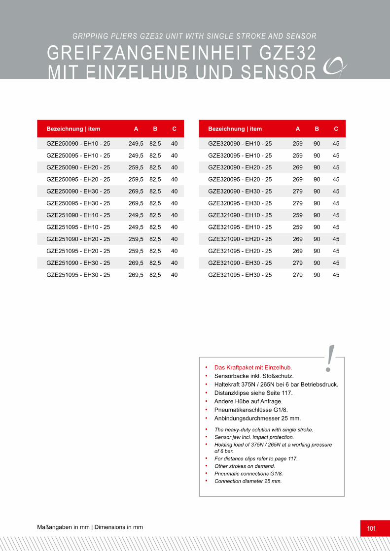
Bezeichnung | item A B CGZE320090 - EH10 - 25 259 90 45GZE320095 - EH10 - 25 259 90 45GZE320090 - EH20 - 25 269 90 45GZE320095 - EH20 - 25 269 90 45GZE320090 - EH30 - 25 279 90 45GZE320095 - EH30 - 25 279 90 45GZE321090 - EH10 - 25 259 90 45GZE321095 - EH10 - 25 259 90 45GZE321090 - EH20 - 25 269 90 45GZE321095 - EH20 - 25 269 90 45GZE321090 - EH30 - 25 279 90 45GZE321095 - EH30 - 25 279 90 45
Bezeichnung | item A B CGZE250090 - EH10 - 25 249,5 82,5 40GZE250095 - EH10 - 25 249,5 82,5 40GZE250090 - EH20 - 25 259,5 82,5 40GZE250095 - EH20 - 25 259,5 82,5 40GZE250090 - EH30 - 25 269,5 82,5 40GZE250095 - EH30 - 25 269,5 82,5 40GZE251090 - EH10 - 25 249,5 82,5 40GZE251095 - EH10 - 25 249,5 82,5 40GZE251090 - EH20 - 25 259,5 82,5 40GZE251095 - EH20 - 25 259,5 82,5 40GZE251090 - EH30 - 25 269,5 82,5 40GZE251095 - EH30 - 25 269,5 82,5 40
• Das Kraftpaket mit Einzelhub.• Sensorbacke inkl. Stoßschutz.• Haltekraft 375N / 265N bei 6 bar Betriebsdruck.• Distanzklipse siehe Seite 117.• Andere Hübe auf Anfrage.• Pneumatikanschlüsse G1/8.• Anbindungsdurchmesser 25 mm.• The heavy-duty solution with single stroke. • Sensor jaw incl. impact protection.• Holding load of 375N / 265N at a working pressure of 6 bar.• For distance clips refer to page 117.• Other strokes on demand.• Pneumatic connections G1/8.• Connection diameter 25 mm.
!
GREIFZANGENEINHEIT GZE32 mIT EINZELHUb UND sENsoRGRIPPING PLIERS GZE32 UNIT wITh SINGLE STROkE AND SENSOR

www.feba-systeme.com102
Bewegliche Vakuumeinheit BVAE32 mit Doppelhub• Wirkprinzip: doppelwirkend.• Befestigungsmöglichkeit an zwei Seiten.• Einstellbare Miniaturgleitführung.• Inklusive Adapter für Vakuumsauger.
• Technische Zeichnung in Ruhestellung• Technical drawing in inoperative position
• Abbildung | picture BVAE32 - DH2020 - 25 DH2020 = Doppelhub mit 20 mm Hub und 20 mm Hub• Picture BVAE32 - DH2020 -25 DH2020 = double stroke with a stroke of 20 mm and another stroke of 20 mm
Bezeichnung | item A B CBVAE32 - DH1010 - 25 201 90 45BVAE32 - DH2010 - 25 211 90 45BVAE32 - DH2020 - 25 221 90 45BVAE32 - DH3020 - 25 231 90 45
bEwEGLIcHE VAKUUmEIN- HEIT bVAE32 mIT DoPPELHUbMOVAbLE VAcUUM UNIT bVAE32 wITh DOUbLE STROkEMovable vacuum unit BVAE32 with double stroke• Activity: double-acting.• Fixing possibility on two sides.• Adjustable low profile linear guide.
• Including adapter for vacuum suction cup.
• Distanzklipse siehe Seite 117.• Saugeradapter siehe Seite 62 und 63.• Anbindungsdurchmesser 25 mm.• For distance clips refer to page 117.• For suction cup adapters refer to pages 62 and 63.• Connection diameter 25 mm.
!

Maßangaben in mm | Dimensions in mm 103103
Bewegliche Vakuumeinheit BVAE32 mit Einzelhub• Wirkprinzip: doppelwirkend.• Befestigungsmöglichkeit an zwei Seiten.• Inklusive Adapter für Vakuumsauger.
• Technische Zeichnung in Ruhestellung• Technical drawing in inoperative position
• Abbildung | picture BVAE32 - EH10 - 25 EH10 = Einzelhub mit 10 mm Hub• Picture BVAE32 - EH10 - 25 EH10 = single stroke with a stroke of 10 mm
Bezeichnung | item A B CBVAE32 - EH10 - 25 128 49,5 45BVAE32 - EH20 - 25 138 49,5 45BVAE32 - EH25 - 25 133 49,5 45BVAE32 - EH30 - 25 148 49,5 45BVAE32 - EH40 - 25 158 49,5 45
Movable vacuum unit BVAE32 with single stroke• Activity: double-acting.• Fixing possibility on two sides.• Including adapter for vacuum suction cup.
• Distanzklipse siehe Seite 117.• Saugeradapter siehe Seite 62 und 63.• Anbindungsdurchmesser 25 mm.• For distance clips refer to page 117.• For suction cup adapters refer to pages 62 and 63.• Connection diameter 25 mm.
!
bEwEGLIcHE VAKUUmEIN- HEIT bVAE32 mIT EINZELHUbMOVAbLE VAcUUM UNIT bVAE32 wITh SINGLE STROkE

www.feba-systeme.com104
Bewegliche Vakuumeinheit BVAE32 mit Doppelhub geführt• Wirkprinzip: doppelwirkend.• Befestigungsmöglichkeit an zwei Seiten.• Einstellbare Miniaturgleitführung.• Inklusive Adapter für Vakuumsauger.
• Technische Zeichnung in Ruhestellung• Technical drawing in inoperative position
• Abbildung | picture BVAE32 - DHG2010 - 25 DHG2010 = Doppelhub mit 10 mm Hub und 20 mm Hub• Picture BVAE32 - DHG2010 -25 DHG2010 = double stroke with a stroke of 10 mm and another stroke of 20 mm
Bezeichnung | item A B CBVAE32 - DHG1010 - 25 211 90 45BVAE32 - DHG2010 - 25 221 90 45BVAE32 - DHG2020 - 25 231 90 45
bEw. VAKUUmEINHEIT bVAE32 mIT DoPPELHUb GEFÜHRTMOVAbLE VAcUUM UNIT bVAE32 wITh DOUbLE STROkE GUIDED Movable vacuum unit BVAE32 with double stroke guided• Activity: double-acting.• Fixing possibility on two sides.• Adjustable low profile linear guide.
• Including adapter for vacuum suction cup.
• Distanzklipse siehe Seite 117.• Saugeradapter siehe Seite 62 und 63.• Anbindungsdurchmesser 25 mm.• For distance clips refer to page 117.• For suction cup adapters refer to pages 62 and 63.• Connection diameter 25 mm.
!
Maßangaben in mm | Dimensions in mm 105105
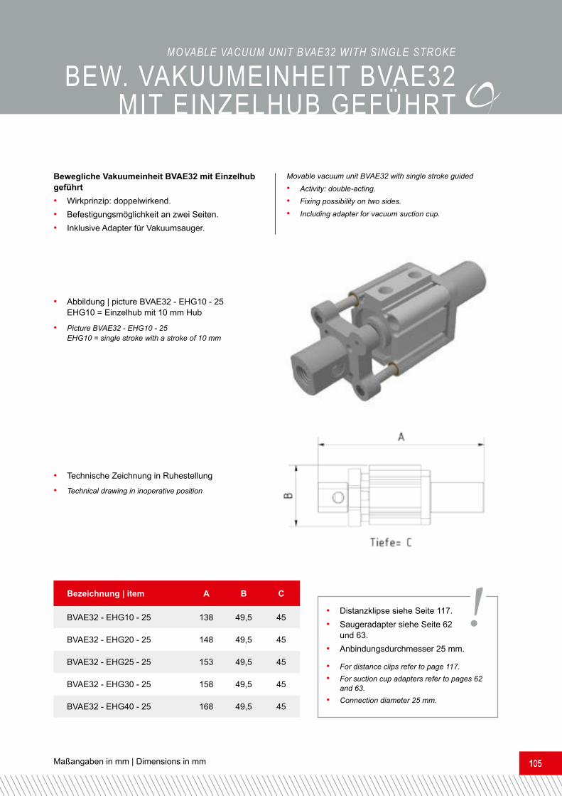
• Technische Zeichnung in Ruhestellung• Technical drawing in inoperative position
• Abbildung | picture BVAE32 - EHG10 - 25 EHG10 = Einzelhub mit 10 mm Hub• Picture BVAE32 - EHG10 - 25 EHG10 = single stroke with a stroke of 10 mm
Bezeichnung | item A B CBVAE32 - EHG10 - 25 138 49,5 45BVAE32 - EHG20 - 25 148 49,5 45BVAE32 - EHG25 - 25 153 49,5 45BVAE32 - EHG30 - 25 158 49,5 45BVAE32 - EHG40 - 25 168 49,5 45• Distanzklipse siehe Seite 117.• Saugeradapter siehe Seite 62 und 63.• Anbindungsdurchmesser 25 mm.• For distance clips refer to page 117.• For suction cup adapters refer to pages 62 and 63.• Connection diameter 25 mm.
!
bEw. VAKUUmEINHEIT bVAE32 mIT EINZELHUb GEFÜHRTMOVAbLE VAcUUM UNIT bVAE32 wITh SINGLE STROkEBewegliche Vakuumeinheit BVAE32 mit Einzelhub geführt• Wirkprinzip: doppelwirkend.• Befestigungsmöglichkeit an zwei Seiten.• Inklusive Adapter für Vakuumsauger.
Movable vacuum unit BVAE32 with single stroke guided• Activity: double-acting.• Fixing possibility on two sides.• Including adapter for vacuum suction cup.

www.feba-systeme.com106
Winkelgreifzangeneinheit WGZE20/WGZE32 mit Doppelhub• Wirkprinzip: doppelwirkend.• Befestigungsmöglichkeit an zwei Seiten.• Einstellbare Miniaturgleitführung.
• Technische Zeichnung, in Arbeitsstellung• Technical drawing, in working position
Movable angle-gripping pliers with double strokewINKELGREIFZANGENEINHEIT mIT DoPPELHUbANGLE GRIPPING PLIERS wITh DOUbLE STROkE
• Activity: double-acting.• Fixing possibility on two sides.• Ball-bearing slides with precision guidance.• Adjustable low profile linear guide.
Bezeichnung | item A B C DWGZE201010-DH3020-25 324 133 45 244,5WGZE321010-DH3020-25 377 133 45 244,5
• Das Kraftpaket mit Doppelhub.• Haltekraft 375N / 265N bei 6 bar Betriebsdruck.• Distanzklipse siehe Seite 117.• Andere Hübe auf Anfrage.• Pneumatikanschlüsse G1/8 / M5.• Anbindungsdurchmesser 25 mm.• Ideal zum Entformen der Softnose bei Matrizenentnahmen.
• The heavy-duty solution with double stroke.• Holding load of 375N / 265N at a working pressure of 6 bar.• For distance clips refer to page 117.• Other strokes on demand.• Pneumatic connections G1/8 / M5.• Connection diameter 25 mm.• Ideal for unmolding the softnose with matrices withdrawals.
!
• Abbildung WGZE201010-DH3020-25• Picture WGZE201010-DH3020-25

Maßangaben in mm | Dimensions in mm 107107
Entnahmegreifer für eine 1fach Kavität (Leiste).Withdrawal gripper for a single cavity (trim).
Entnahmegreifer für eine 1+1fach Kavität (Rahmen).Withdrawal gripper for a single + single cavity (frame).

www.feba-systeme.com108
HUbbEGRENZER FÜR DoPPELHÜbEHubbegrenzer für DoppelhübeVereinfacht das genaue Einstellen der Entformungshübe.
• Abbildung | picture HBDH32
Bezeichnung | item A B C DHBDH25-10 49 18,5 34,5 12HBDH25-20 49 18,5 44,5 12HBDH32-10 54 27,5 34,5 16HBDH32-20 54 27,5 44,5 16
Stroke Limitation for double stroke Simplifies the exact setting of the demolding strokes.
STROkE LIMITATION FOR DOUbLE STROkE
• Kann problemlos nachgerüstet werden.• Material: Aluminium oder Kunststoff.• Passende Kompaktzylinder siehe Seite 72.• Passende Greif- und Hubeinheiten siehe Seite 96 bis 106.• Mit Einstellskala erhältlich.
• Can be retrofitted easily.• Material: Aluminum or plastic.• For suitable compact cylinders refer to page 72.• For suitable gripping and stroke units refer to pages 96 to 106.• Available with setting scale.
!
• Technische Zeichnung, in Arbeitsstellung• Technical drawing, in working position• Anwendungsbeispiel | usage example

Maßangaben in mm | Dimensions in mm 109109
Vorrichtung zur Montage von Clipsen mit anschließender Positionskontrolle.Device for mounting of clips followed by position control.

www.feba-systeme.com110
GREIFFINGER GF14GRIPPING FINGERS GF14Greiffinger GF14• Wirkprinzip: einfachwirkend.• Mit M12 x 1 Gewinde.
• Technische Zeichnung | technical drawing
• Technische Zeichnung | technical drawing
• Technische Zeichnung | technical drawing• Abbildung | picture GF14 - 120
Bezeichnung | item A B C DGF14 - 35 74 14 M12x1 35°GF14 - 95 75 14 M12x1 95°GF14 - 120 73 14 M12x1 120°
Gripping fingers GF14
• Activity: single-acting.• With thread M12 x 1.
• Verlängerungsrohr siehe Seite 70.• Haltekraft 20N bei 6 bar Betriebsdruck.• Pneumatikanschluss M5.• For extension pipes refer to page 70.• Holding load of 20N at a working pressure of 6 bar.• Pneumatic connection M5.
!
• Abbildung | picture GF14 - 95
• Abbildung | picture GF14 - 35
NEW!
Maßangaben in mm | Dimensions in mm 111111
• Technische Zeichnung | technical drawing
• Technische Zeichnung | technical drawing
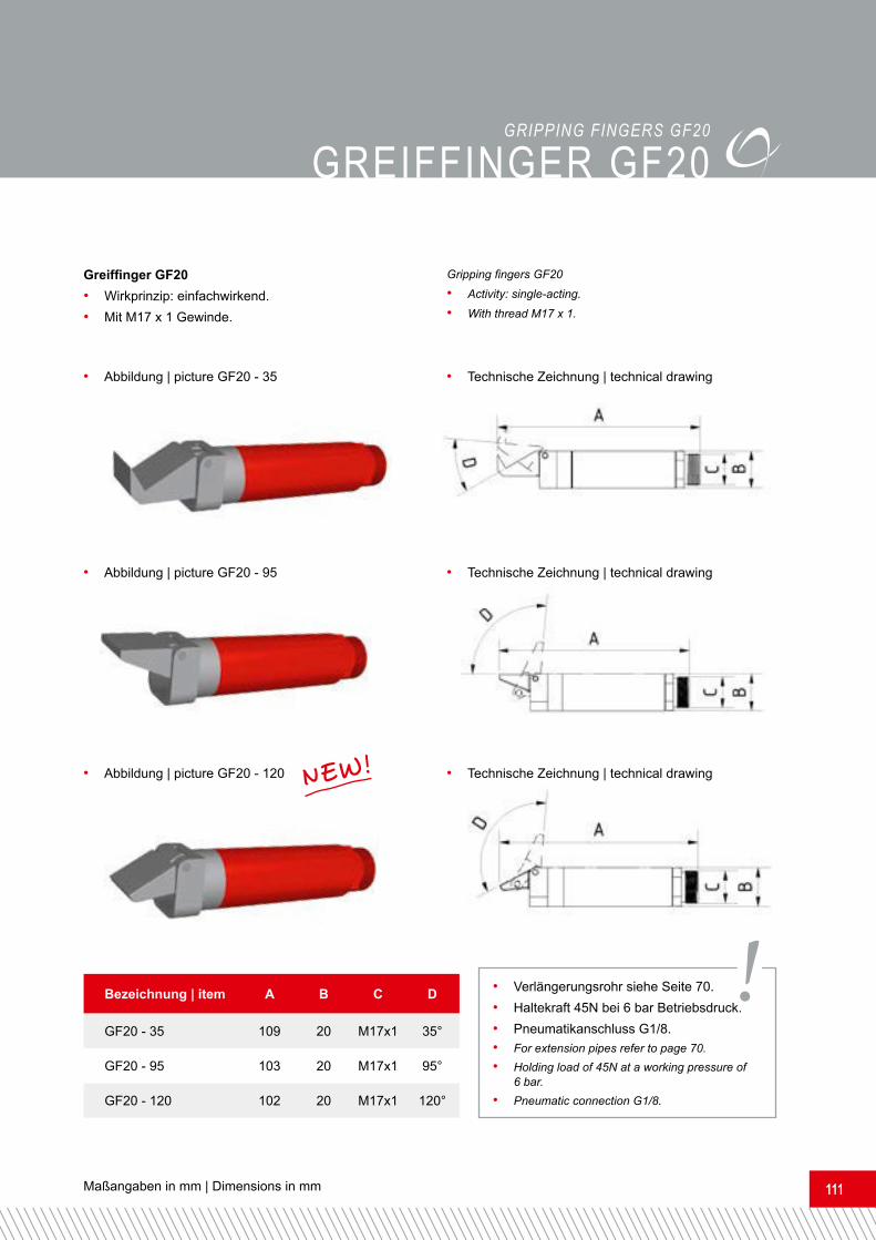
• Technische Zeichnung | technical drawing• Abbildung | picture GF20 - 120
Bezeichnung | item A B C DGF20 - 35 109 20 M17x1 35°GF20 - 95 103 20 M17x1 95°GF20 - 120 102 20 M17x1 120°• Verlängerungsrohr siehe Seite 70.• Haltekraft 45N bei 6 bar Betriebsdruck.• Pneumatikanschluss G1/8.• For extension pipes refer to page 70.• Holding load of 45N at a working pressure of 6 bar.• Pneumatic connection G1/8.
!
• Abbildung | picture GF20 - 95
• Abbildung | picture GF20 - 35
NEW!GREIFFINGER GF20GRIPPING FINGERS GF20
Greiffinger GF20• Wirkprinzip: einfachwirkend.• Mit M17 x 1 Gewinde.
Gripping fingers GF20
• Activity: single-acting.• With thread M17 x 1.

www.feba-systeme.com116
GEGENHALTER GREIFFINGERGegenhalter Greiffinger mit gummierter Auflage.
• Technische Zeichnung | technical drawing
• Abbildung | picture GH - GF20D20
Bezeichnung | item A B C DGH - GF14D14 40,5 24 14 22,5GH - GF20D20 47,3 30 20 28,5GH - GF20D25 47,3 30 25 28,5
• Gummierte und silikonfreie Auflage. • Rubberized and silicone-free layer.
FIXING DEVIcES FOR GRIPPING FINGERSFixing devices for gripping fingers with a rubberized layer.
!• Anwendungsbeispiel | usage example

Maßangaben in mm | Dimensions in mm 117117
Distanzklipse zum Reduzieren der Einfahrwege von Kompaktzylindern.
• Technische Zeichnung | technical drawing
• Abbildung | picture DK16 - 5
DIsTANZKLIPsE
Bezeichnung | item A B CDK16 - 3 24 16 3DK16 - 5 24 16 5DK16 - 10 24 16 10
• Material: Kunststoff • Material: plastic
DISTANcE cLIPSDistance clips used to reduce the strokes of cylinders.
!
www.feba-systeme.com118
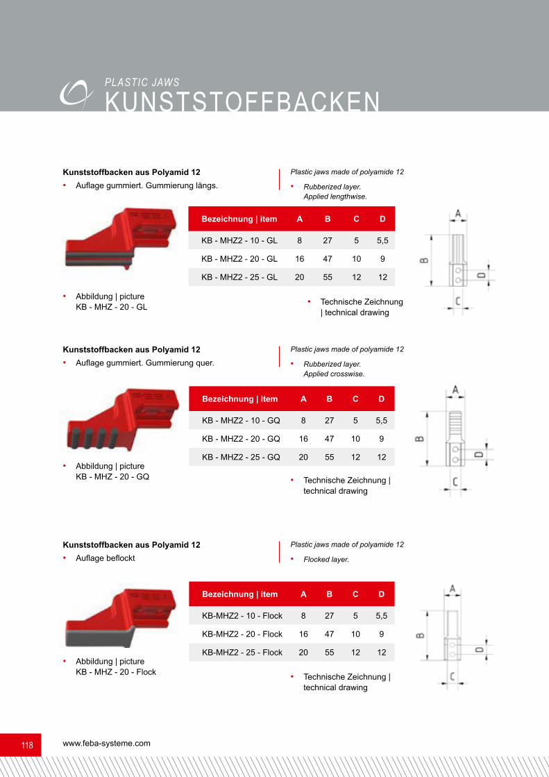
Kunststoffbacken aus Polyamid 12• Auflage gummiert. Gummierung längs.
Kunststoffbacken aus Polyamid 12• Auflage gummiert. Gummierung quer.
Kunststoffbacken aus Polyamid 12• Auflage beflockt
• Technische Zeichnung | technical drawing
• Technische Zeichnung | technical drawing
• Technische Zeichnung | technical drawing
• Abbildung | picture KB - MHZ - 20 - GL
• Abbildung | picture KB - MHZ - 20 - GQ
• Abbildung | picture KB - MHZ - 20 - Flock
Bezeichnung | item A B C DKB - MHZ2 - 10 - GL 8 27 5 5,5KB - MHZ2 - 20 - GL 16 47 10 9KB - MHZ2 - 25 - GL 20 55 12 12
Bezeichnung | item A B C DKB - MHZ2 - 10 - GQ 8 27 5 5,5KB - MHZ2 - 20 - GQ 16 47 10 9KB - MHZ2 - 25 - GQ 20 55 12 12
Bezeichnung | item A B C DKB-MHZ2 - 10 - Flock 8 27 5 5,5KB-MHZ2 - 20 - Flock 16 47 10 9KB-MHZ2 - 25 - Flock 20 55 12 12
Plastic jaws made of polyamide 12• Rubberized layer. Applied lengthwise.
Plastic jaws made of polyamide 12• Rubberized layer. Applied crosswise.
Plastic jaws made of polyamide 12• Flocked layer.
KUNsTsToFFbAcKENPLASTIc JAwS

Maßangaben in mm | Dimensions in mm 119119
sENsoRHALTER sH25 für wTb8SENSOR DEVIcES Sh25 FOR wTb8
• Material: Kunststoff • Material: plastic
• Abbildung | picture SH25 - WTB8
Bezeichnung | item A B C D ESH25-WTB8 42 65 35 25 43SH25-GTB6 42 65 35 25 43
Sensorhalter SH25 für WTB8• leichte Montierbarkeit• schützt umlaufend• sehr leicht
• Technische Zeichnung | technical drawing
Sensor devices SH25 for WTB8• easy to mount• protects circumferential• very light
!

www.feba-systeme.com120
REFLExIoNsLIcHTTAsTER REFLEcTION LIGhT SwITch
• Material: Kunststoff • Material: plasticBezeichnung | item A B C D E FFB-WTB8-P2111 31 20 42 25,4 3 11FB-GTB6-P5211 31,5 21 42 25,4 3 12FB-WTB190TL-P460 44,4 32 53,7 39,2 2,8 15FB-WT2S-P131 20,6 12,5 25,1 15 2,9 7,6FB-WT2S-P111 20,6 12,5 25,1 15 2,9 7,6FB-WT150-P460 28 18 38,2 23 2,6 10
Reflexionslichttaster• Hintergrundausleuchtung• Standard-Miniaturgehäuse• mit integrierten M3-Befestigungsgewinden• 11mm x 31mm x 20mm• Schaltabstand max. 5mm - 100mm• Schaltabstand 20mm - 100mm• Lichtart: sichtbares Rotlicht• Stecker M8, 3-polig
Reflection Light Switch
• background suppression• standard miniature housing with M3 threaded mounting holes• 11mm x 31mm x 20mm• sensing range max. 5mm - 100mm• sensing range 20mm - 100mm• type of light: visible redlight• connector M8, 3-pin
!
• Abbildung | picture FB - WTB8 - P2111 • Technische Zeichnung | technical drawing

Maßangaben in mm | Dimensions in mm 121121
sENsoREN oPTIscH OPTIcAL SENSORSFB - OTQ - 40100 - 2,0 - 00• Optischer Sensor• Taster 4 x 44,8 x 6,2 mm• Rotlicht• HGA• 11-30VDC• 50mA • Sn: 30fix• Kabellänge 2 mFB - OTQ - 40173 - 0,2 - M8• Optischer Sensor• Taster 4 x 44,8 x 6,2 mm• Rotlicht• HGA• 11-30VDC• 50mA • Sn: 50fix• M8 Stecker, 4-polig
• Technische Zeichnung | technical drawing• Abbildung | picture FB - OTQ - 40100 - 2,0 - 00Bezeichnung | item A B C DFB - OTQ - 40100 - 2,0 - 00 45 6,8 4 5FB - OTQ - 40173 - 0,2 - M8 45 6,8 4 5
FB - OTQ - 40100 - 2,0 - 00• Optical sensor• Design 4 x 44,8 x 6,2 mm• redlight• HGA• 11-30VDC• 50mA• Sn: 30fix• length of cable 2 mFB - OTQ - 40173 - 2,0 - 00• Optical sensor• Design 4 x 44,8 x 6,2 mm• redlight• HGA• 11-30VDC• 50mA• Sn: 50fix• M8 connector, 4-pin

www.feba-systeme.com122
FB - BI2 - Q5,5 - AP6X• Induktiver Sensor• Quaderförmig• Höhe 5.5 mm• aktive Fläche oben• Kunststoff, PP• DC 3-Draht, 10...30 VDC, Schließer,
PNP-Ausgang, Kabelanschluss• Kabellänge 2 m• Bemessungsschaltabstand: 2 mm, bündigFB - BI2 - Q5,5 - AP6X - 0,3 - PS• Induktiver Sensor• Quaderförmig• Höhe 5.5 mm• aktive Fläche oben• Kunststoff, PP• DC 3-Draht, 10...30 VDC, Schließer,
PNP-Ausgang, Steckverbinder, M8 x 1• Kabellänge 0,3 m • Bemessungsschaltabstand: 2 mm, bündig
• Technische Zeichnung | technical drawing• Abbildung | picture FB - BI2 - Q5,5 - AP6X
sENsoREN INDUKTIV
Bezeichnung | item A B CFB - BI2 - Q5,5 - AP6X 28 5,5 8FB - BI2 - Q5,5 - AP6X - 0,3 - PS 28 5,5 8
FB - BI2 - Q5,5 - AP6X• inductive sensor• cuboid• height = 5.5 mm• active surface on top• plastic, PP• DC3 wire, 10...30 VDC, make contact, PNP output, cable connection• length of cable: 2 m• reference switching distance: 2 mm, flush
FB - BI2 - Q5,5 - AP6X - 0,3 - PS• inductive sensor• cuboid• height = 5.5 mm• active surface on top• plastic, PP• DC3 wire, 10...30 VDC make contact, PNP output, pin-and-socket connector, M8 x 1• length of cable: 0.3 m• reference switching distance: 2 mm, flush
INDUcTIVE SENSORS
Maßangaben in mm | Dimensions in mm 123123
sENsoREN INDUKTIVINDUcTIVE SENSORS
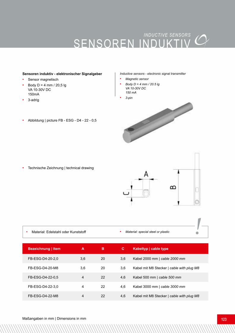
• Abbildung | picture FB - ESG - D4 - 22 - 0,5
Bezeichnung | item A B C Kabeltyp | cable typeFB-ESG-D4-20-2,0 3,6 20 3,6 Kabel 2000 mm | cable 2000 mmFB-ESG-D4-20-M8 3,6 20 3,6 Kabel mit M8 Stecker | cable with plug M8FB-ESG-D4-22-0,5 4 22 4,6 Kabel 500 mm | cable 500 mmFB-ESG-D4-22-3,0 4 22 4,6 Kabel 3000 mm | cable 3000 mmFB-ESG-D4-22-M8 4 22 4,6 Kabel mit M8 Stecker | cable with plug M8
Sensoren induktiv - elektronischer Signalgeber• Sensor magnetisch• Body D = 4 mm / 20,5 lg VA 10-30V DC 150mA• 3-adrig
• Technische Zeichnung | technical drawing
Inductive sensors - electronic signal transmitter• Magnetic sensor• Body D = 4 mm / 20.5 lg VA 10-30V DC 150 mA• 3-pin
• Material: Edelstahl oder Kunststoff • Material: special steel or plastic !
www.feba-systeme.com124
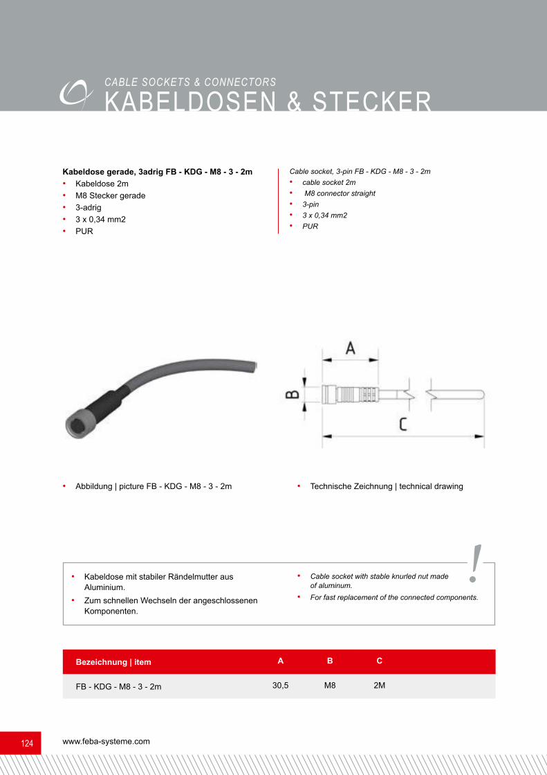
KAbELDosEN & sTEcKERcAbLE SOckETS & cONNEcTORSKabeldose gerade, 3adrig FB - KDG - M8 - 3 - 2m• Kabeldose 2m • M8 Stecker gerade• 3-adrig• 3 x 0,34 mm2• PUR
Cable socket, 3-pin FB - KDG - M8 - 3 - 2m• cable socket 2m• M8 connector straight• 3-pin• 3 x 0,34 mm2• PUR
• Technische Zeichnung | technical drawing• Abbildung | picture FB - KDG - M8 - 3 - 2m
Bezeichnung | item A B CFB - KDG - M8 - 3 - 2m 30,5 M8 2M
• Kabeldose mit stabiler Rändelmutter aus Aluminium.• Zum schnellen Wechseln der angeschlossenen Komponenten. • Cable socket with stable knurled nut made of aluminum.
• For fast replacement of the connected components.!

Maßangaben in mm | Dimensions in mm 125125
KAbELDosEN & sTEcKERcAbLE SOckETS & cONNEcTORS
• Technische Zeichnung | technical drawing• Abbildung | picture FB - EST - M8 - 3P
Bezeichnung | item A B CFB - EST - M8 - 3P 43 M8 Durchmesser 12,5FB - SACC - M12MS - 4CON - PG7 - M 60 M12 Durchmesser 20
FB - EST - M8 - 3P• Sensor-/ Aktor-Steckverbindung• M8 Stecker gerade• 3-polig • A-kodiert • max. Kabelaußendurchmesser 5 mm
FB - SACC - M12MS - 4CON - PG7 - M• Sensor-/ Aktor-Steckverbindung • M12 Stecker gerade• 4-polig • A-kodiert • Schraubanschluss Pg7
FB - EST - M8 - 3P• Sensor-/actuator connector• M8 connector straight• 3-pin• A-coded• max. cable diameter 5.0 mmFB - SACC - M12MS - 4CON - PG7 - M• Sensor-/actuator connector• M12 connector straight• 4-pin• A-coded• screw connection Pg7

www.feba-systeme.com126
ELEKTRoVERTEILERboxEN
Elektroverteilerboxen inkl. EASY - Klips• Problemloses Anbringen der EVB am Tragrohr
durch EASY-KLIP-FUNKTION möglich.• Kein aufwendiges Verschrauben auf einer Alumini-umträgerplatte notwendig.• Signalanzeige über LEDs.
• Technische Zeichnung | technical drawing• Abbildung | picture EVB - LED - 19 - 40Bezeichnung | item A B C D Inkl. Halteklips für Aluminiumrohr |
incl. fixing clips for aluminum pipe Kabel / Ausgänge cable / outputsEVB-LED-19-25 118 62 25 145 AR25 x 5 ohne Kabel, Anzahl der Ausgänge = 19without cable, numbers of outputs = 19EVB-LED-19-40 118 72 40 145 AR40 x 4EVB-LED-19-25-1m 118 62 25 145 AR40 x 4 inklusive 1m Kabel 25adrig,Anzahl der Ausgänge = 19incl. 1 m cable with 25 leads,numbers of outputs = 19EVB-LED-19-40-1m 118 72 40 145 AR40 x 4EVB-LED-19-25-1m-ST 118 72 25 145 AR40 x 4 in inklusive Schunk-Stecker, 1m Kabel 25adrig, Anzahl der Ausgänge = 19including Schunk-connector, 1 m cable with 25 leads, numbers of outputs = 19EVB-LED-19-40-1m-ST 118 72 40 145 AR40 x 4
Electrical distribution boxes (EDB) incl. EASY clips• Unproblematic fixing of the EDB at the stay pipe.
• No necessity for a complex screwing down on an aluminum plate.• signal display by LEDs.
ELEcTRIcAL DISTRIbUTION bOXES

ADAPTER / ADAPTERPLATTEN / ADAPTERRINGEALUmINIUm PRoFILEANGUssscHNEIDZANGENAUFNAHmENALUmINIUmRoHREHUbbEGRENZERDREHANTRIEbE ELEKTRoVERTEILERboxENGREIFARmEGREIFFINGERGREIFZANGENKLEmmsTÜcKEKNIEGELENKEKREUZ- / PARALLEL- / wINKELKLEmmENKREUZVERbINDUNGsbRÜcKEN / -PLATTENKUNsTsToFFbAcKENmINIATUR- / KomPAKTZyLINDERNUTENsTEINEPARALLELGREIFERsAUGER- / ZyLINDER- / GREIFERADAPTERsENsoRENPNEUmATIK ZUbEHÖRVERLÄNGERUNGENVERLÄNGERUNGsRoHREVERscHLUssKAPPENwINKELGREIFARmE
ADAPTER / ADAPTER PLATEs / ADAPTER RINGsALUmINUm PRoFILEssPRUE cUTTERREcEPTAcLEsALUmINUm PIPEsHUb LImITATIoNRoTATING DRIVE UNITs ELEcTRIcAL DIsTRIbUTIoN boxEsANGULAR ARmsGRIPPING FINGERsGRIPPING PLIERscLAmPsELbow JoINTscRoss-/ PARALLEL-/ ELbow-cLAmPscRoss coNNEcTING bRIDGEs /-PLATEsPLAsTIc JAwsmINIATURE- / comPAcT cyLINDERsNUT x PRoFILEsPARALLEL GRIPPERssUcTIoN -/ cyLINDER-/ GRIPPING ADAPTERssENsoRsPNEUmATIc AccEssoRIEsExTENsIoNsExTENsIoN PIPEssEALING cAPsANGULAR ARms
FEBA AUTOMATION & Modulare Systeme GmbH Am Bahnhof 1557392 Schmallenberg t +49 29 72 / 962 17 11 f +49 29 72 / 962 17 15 [email protected] | CONTACT PRODUKTK
ATALOG I Ausgabe 09
/2016PRODUCT
CATALOGUE