QBericht neues-Logo Formatvorlage
31
Fraunhofer-Institut für Produktionstechnik und Automatisierung Institutsleiter Prof. Dr.-Ing. Prof. e.h. Dr.-Ing. e.h. Dr. h.c. mult. Engelbert Westkämper Prof. Dr.-Ing. Alexander Verl Nobelstraße 12 70569 Stuttgart Telefon + 49 (0) 711 / 9 70-00 Telefax + 49 (0) 711 / 9 70-1399 Stuttgart, Germany, August 31, 2012 Measurement Report Cleanroom suitability tests on materials used by Tarkett AB Customer: Tarkett AB 372 73 Ronneby Sweden Project Manager: Dr.-Ing. Dipl.-Phys. Udo Gommel Report No. TA 1206-603
Transcript of QBericht neues-Logo Formatvorlage
Fraunhofer-Institut für Produktionstechnik und Automatisierung Institutsleiter Prof. Dr.-Ing. Prof. e.h. Dr.-Ing. e.h. Dr. h.c. mult. Engelbert Westkämper Prof. Dr.-Ing. Alexander Verl Nobelstraße 12 70569 Stuttgart Telefon + 49 (0) 711 / 9 70-00 Telefax + 49 (0) 711 / 9 70-1399
Stuttgart, Germany, August 31, 2012
Measurement Report
Cleanroom suitability tests on materials used by Tarkett AB
Customer: Tarkett AB
372 73 Ronneby
Sweden
Project Manager: Dr.-Ing. Dipl.-Phys. Udo Gommel
Report No. TA 1206-603
Cleanroom suitability tests on materials used by Tarkett AB Fraunhofer IPA 2 Report No.: TA 1206-603
Index
1 Introduction and objectives 4
2 Overview of results 5
3 Airborne particle emission tests on application of tribological stress 6
3.1 Procedure for particle emission tests 6
3.1.1 Cleanroom-suitable material test bench 6
3.1.2 Test parameters 9
3.1.3 Cleanroom environment 10
3.1.4 Particle measuring technique 10
3.1.5 Test procedure 11
3.2 Material samples for particle emission tests 11
3.3 Particle emission results 12
3.3.1 Differential progression of particle emission 12
3.3.2 Size distribution of the emitted particles 13
3.3.3 Classification 14
3.4 Comparison of Classifications of Airborne Particulate Contamination 17
4 Outgassing tests under thermal stress 18
4.1 Material samples 18
4.2 Outgassing test procedure 19
4.2.1 Sampling chamber 20
4.2.2 Analysis devices 22
4.3 Outgassing results 23
4.4 Classification 23
Cleanroom suitability tests on materials used by Tarkett AB Fraunhofer IPA 3 Report No.: TA 1206-603
4.5 Detection limit 24
4.5.1 General explanation of chromatograms 25
4.5.2 Primo Premium 26
Cleanroom suitability tests on materials used by Tarkett AB Fraunhofer IPA 4 Report No.: TA 1206-603
1 Introduction and objectives
Tarkett AB is an established manufacturer of sustainable PVC flooring systems. The components are produced under high quality requirements and are suc-cessfully implemented in a wide range of industries.
To secure the market position of Tarkett AB in the sector of cleanroom tech-nology, the aim is to identify optimization potentials for its products. The suit-ability of a product for use in clean areas is significantly influenced by the ma-terials used in its manufacture.
The industrial alliance »Cleanroom Suitable Materials CSM« has developed procedures for determining the cleanroom suitability of materials. Depending on the area of implementation concerned, the behavior of materials with re-gard to particle emission and outgassing is taken into consideration. The tests are carried out in a standardized way in compliance with relevant national and international norms.
The results obtained provide an objective and substantiated basis for compari-son and can be referred to when selecting suitable materials for specific manu-facturing environments and areas of implementation. In consequence, this im-proves the cleanroom suitability of the respective products.
Cleanroom suitability tests on materials used by Tarkett AB Fraunhofer IPA 5 Report No.: TA 1206-603
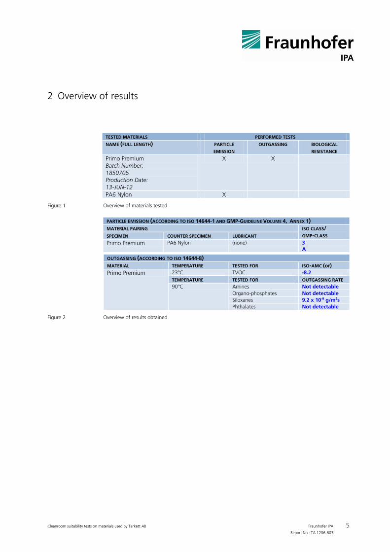
2 Overview of results
TESTED MATERIALS PERFORMED TESTS
NAME (FULL LENGTH) PARTICLE
EMISSION OUTGASSING BIOLOGICAL
RESISTANCE
Primo Premium Batch Number: 1850706 Production Date: 13-JUN-12
X X
PA6 Nylon X
Figure 1 Overview of materials tested
PARTICLE EMISSION (ACCORDING TO ISO 14644-1 AND GMP-GUIDELINE VOLUME 4, ANNEX 1)
MATERIAL PAIRING ISO CLASS/ GMP-CLASS SPECIMEN COUNTER SPECIMEN LUBRICANT
Primo Premium PA6 Nylon (none) 3 A
OUTGASSING (ACCORDING TO ISO 14644-8)
MATERIAL TEMPERATURE TESTED FOR ISO-AMC (or)
Primo Premium 23°C TVOC -8.2
TEMPERATURE TESTED FOR OUTGASSING RATE 90°C Amines Not detectable
Organo-phosphates Not detectable
Siloxanes 9.2 x 10⁻⁹ g/m2s
Phthalates Not detectable
Figure 2 Overview of results obtained
Cleanroom suitability tests on materials used by Tarkett AB Fraunhofer IPA 6 Report No.: TA 1206-603
3 Airborne particle emission tests on application of tribological stress
3.1 Procedure for particle emission tests
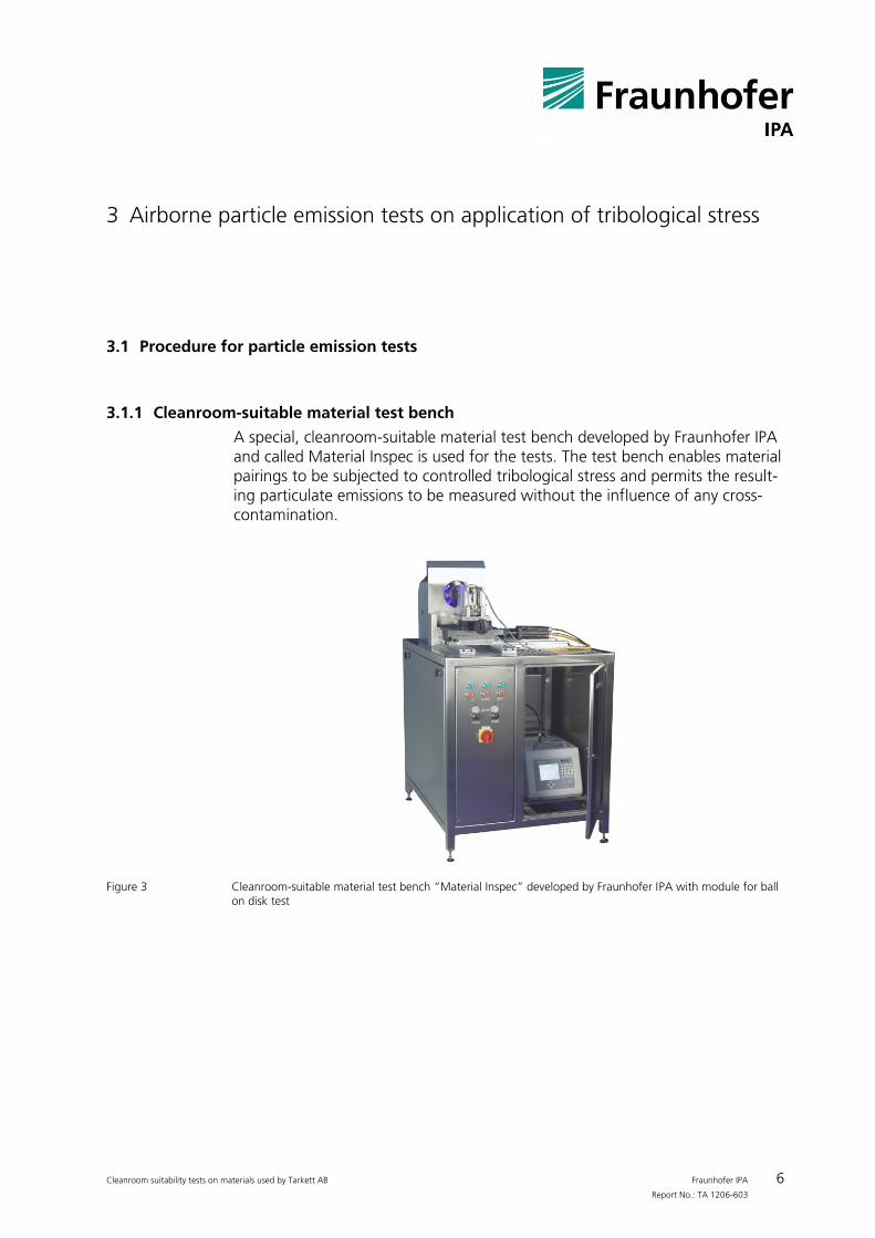
3.1.1 Cleanroom-suitable material test bench
A special, cleanroom-suitable material test bench developed by Fraunhofer IPA and called Material Inspec is used for the tests. The test bench enables material pairings to be subjected to controlled tribological stress and permits the result-ing particulate emissions to be measured without the influence of any cross-contamination.
Figure 3 Cleanroom-suitable material test bench “Material Inspec” developed by Fraunhofer IPA with module for ball
on disk test
Cleanroom suitability tests on materials used by Tarkett AB Fraunhofer IPA 7 Report No.: TA 1206-603
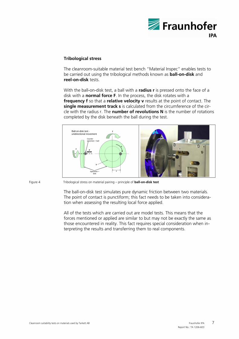
Tribological stress
The cleanroom-suitable material test bench “Material Inspec” enables tests to be carried out using the tribological methods known as ball-on-disk and reel-on-disk tests.
With the ball-on-disk test, a ball with a radius r is pressed onto the face of a disk with a normal force F. In the process, the disk rotates with a frequency f so that a relative velocity v results at the point of contact. The single measurement track s is calculated from the circumference of the cir-cle with the radius r. The number of revolutions N is the number of rotations completed by the disk beneath the ball during the test.
Ball-on-disk test -
unidirectional movementf
Specimen =
disk
r
s
Ff
Counter
specimen = ball
v
Figure 4 Tribological stress on material pairing – principle of ball-on-disk test
The ball-on-disk test simulates pure dynamic friction between two materials. The point of contact is punctiform; this fact needs to be taken into considera-tion when assessing the resulting local force applied.
All of the tests which are carried out are model tests. This means that the forces mentioned or applied are similar to but may not be exactly the same as those encountered in reality. This fact requires special consideration when in-terpreting the results and transferring them to real components.
Cleanroom suitability tests on materials used by Tarkett AB Fraunhofer IPA 8 Report No.: TA 1206-603
3.1.1.1 Force transmission and measurement recordings
The normal force is applied using a force transmission unit. For the ball-on-disk test, dead weights are implemented. For the reel-on-disk test, steel springs are utilized because of the increased forces.
The normal force applied is recorded continuously during the test using a load cell based on the principle of the strain gauge. With the ball-on-disk test, in addition to the normal force, the frictional force acting vertically downwards at the point of contact is also recorded synchron-ously. This enables the progression of the friction coefficient to be deter-mined as the ratio between frictional force and normal force.
Particle measurement Particulate emissions are measured directly beneath the point of contact of the material test specimen. In the case of the ball-on-disk test (punctiform contact of the test specimen), a chamfered particle probe tube is used. With the reel-on-disk test, because of the broader line-shaped contact, a cylindrical particle probe with an aperture of 35 mm in diameter is used. The area of contact has been specially designed from an airflow point of view to ensure that the majority of particles emitted are detected.
Cleanroom suitability tests on materials used by Tarkett AB Fraunhofer IPA 9 Report No.: TA 1206-603
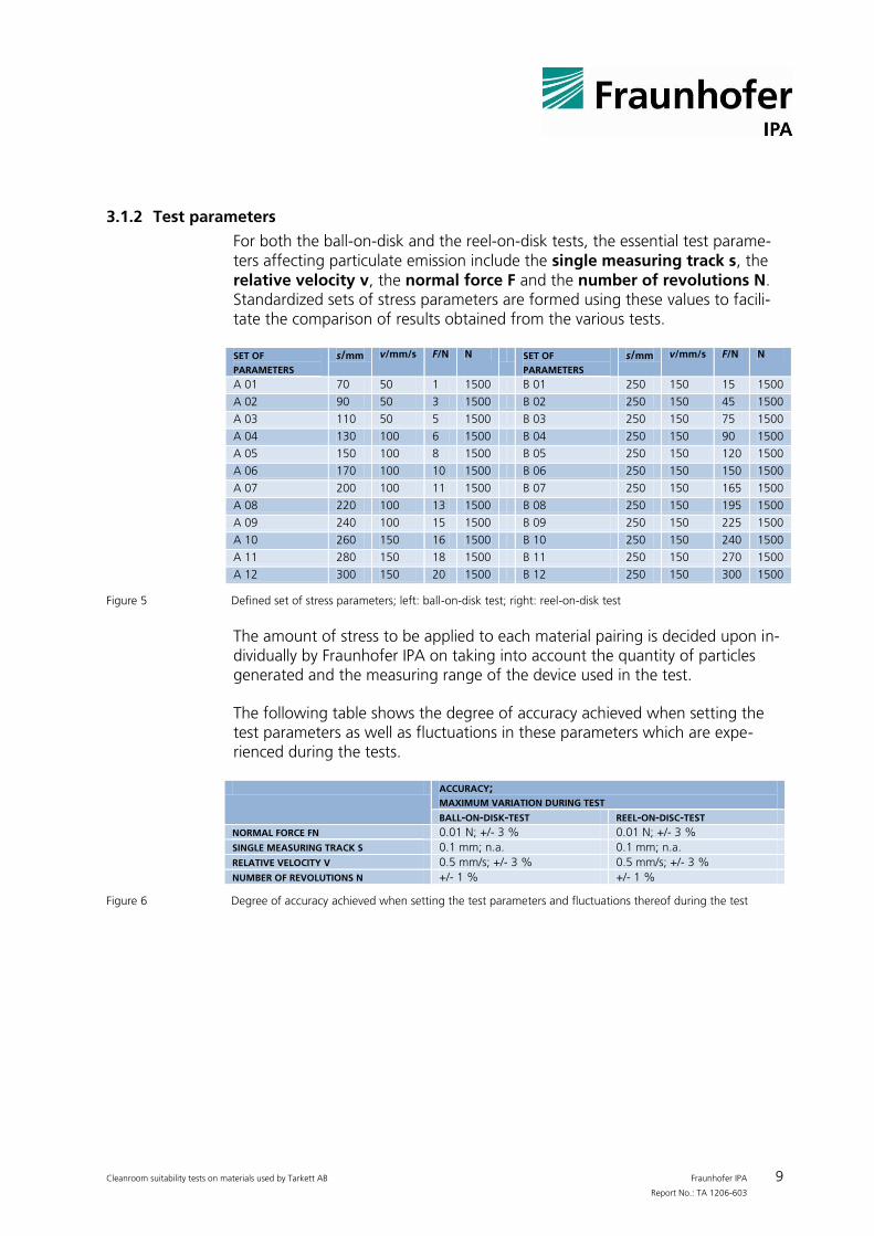
3.1.2 Test parameters
For both the ball-on-disk and the reel-on-disk tests, the essential test parame-ters affecting particulate emission include the single measuring track s, the relative velocity v, the normal force F and the number of revolutions N. Standardized sets of stress parameters are formed using these values to facili-tate the comparison of results obtained from the various tests.
SET OF
PARAMETERS s/mm v/mm/s F/N N SET OF
PARAMETERS s/mm v/mm/s F/N N
A 01 70 50 1 1500 B 01 250 150 15 1500
A 02 90 50 3 1500 B 02 250 150 45 1500
A 03 110 50 5 1500 B 03 250 150 75 1500
A 04 130 100 6 1500 B 04 250 150 90 1500
A 05 150 100 8 1500 B 05 250 150 120 1500
A 06 170 100 10 1500 B 06 250 150 150 1500
A 07 200 100 11 1500 B 07 250 150 165 1500
A 08 220 100 13 1500 B 08 250 150 195 1500
A 09 240 100 15 1500 B 09 250 150 225 1500
A 10 260 150 16 1500 B 10 250 150 240 1500
A 11 280 150 18 1500 B 11 250 150 270 1500
A 12 300 150 20 1500 B 12 250 150 300 1500
Figure 5 Defined set of stress parameters; left: ball-on-disk test; right: reel-on-disk test
The amount of stress to be applied to each material pairing is decided upon in-dividually by Fraunhofer IPA on taking into account the quantity of particles generated and the measuring range of the device used in the test.
The following table shows the degree of accuracy achieved when setting the test parameters as well as fluctuations in these parameters which are expe-rienced during the tests.
ACCURACY; MAXIMUM VARIATION DURING TEST
BALL-ON-DISK-TEST REEL-ON-DISC-TEST
NORMAL FORCE FN 0.01 N; +/- 3 % 0.01 N; +/- 3 %
SINGLE MEASURING TRACK S 0.1 mm; n.a. 0.1 mm; n.a.
RELATIVE VELOCITY V 0.5 mm/s; +/- 3 % 0.5 mm/s; +/- 3 %
NUMBER OF REVOLUTIONS N +/- 1 % +/- 1 %
Figure 6 Degree of accuracy achieved when setting the test parameters and fluctuations thereof during the test
Cleanroom suitability tests on materials used by Tarkett AB Fraunhofer IPA 10 Report No.: TA 1206-603
3.1.3 Cleanroom environment
All tests are carried out at the Fraunhofer IPA test center for semiconductor equipment. Measurements are taken in a cleanroom fulfilling Class 1 specifica-tions (in accordance with ISO 14644-1). A vertical, unidirectional airflow pre-vails in the cleanroom with a first air flow velocity of 0.45 m/s. Environmental conditions are kept constant with a room temperature of 22 °C ± 0.5 °C and a relative humidity of 45 % ± 5 %.
In compliance with ISO 14644-1, Cleanroom “Class 1” means that only two particles the size of 0.2 µm may be found in a reference volume of one cubic meter in the first air (filtered air introduced into the cleanroom). In practical operation, even fewer particles are found in this class.
3.1.4 Particle measuring technique
Optical particle counters are utilized to determine particle emission during the tests.
Optical particle counters function according to the theory of scattered light. Using a sampling probe, a defined volume of air of 1 cubic foot (1 cft = 28.3 li-ters) is sucked in per minute and guided into a measuring chamber via a tube connected to it. The air sucked in is illuminated by a laser beam. As soon as a particle carried by the airflow is hit by a light ray, the light is scattered and re-corded by photo-detectors.
The amount of impulses registered equates to the number of particles found in the volume of air; the height of the impulse gives an indication of particle size.
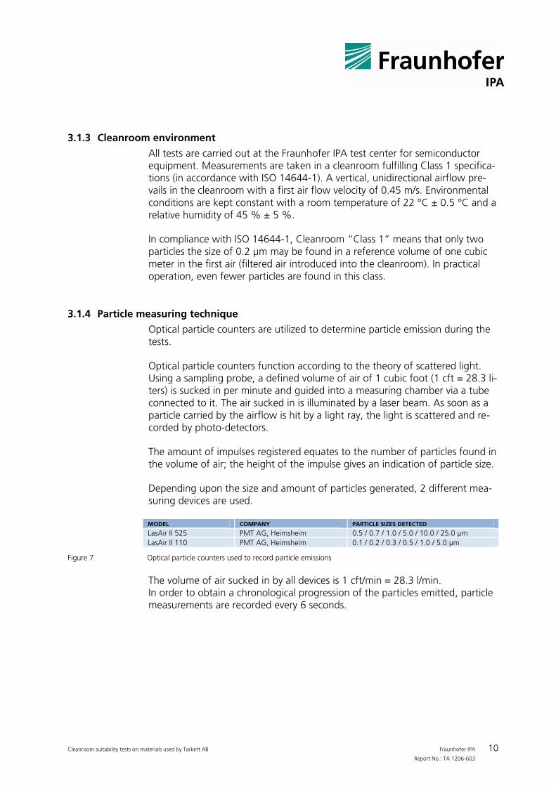
Depending upon the size and amount of particles generated, 2 different mea-suring devices are used.
MODEL COMPANY PARTICLE SIZES DETECTED
LasAir II 525 PMT AG, Heimsheim 0.5 / 0.7 / 1.0 / 5.0 / 10.0 / 25.0 µm
LasAir II 110 PMT AG, Heimsheim 0.1 / 0.2 / 0.3 / 0.5 / 1.0 / 5.0 µm
Figure 7 Optical particle counters used to record particle emissions
The volume of air sucked in by all devices is 1 cft/min = 28.3 l/min. In order to obtain a chronological progression of the particles emitted, particle measurements are recorded every 6 seconds.
Cleanroom suitability tests on materials used by Tarkett AB Fraunhofer IPA 11 Report No.: TA 1206-603
3.1.5 Test procedure
The test specimens are introduced into the cleanroom before the tests are commenced. In the process, the surfaces of the test pieces are cleaned to re-move any sedimented particles or filmy contamination which may be present.
The tribological reel-on-disk tests are carried out using 1 different set of stress parameters, taking into account the quantity of particles generated. To ensure reliability of the results, 10 repetition tests are carried out for the cho-sen stress parameter.
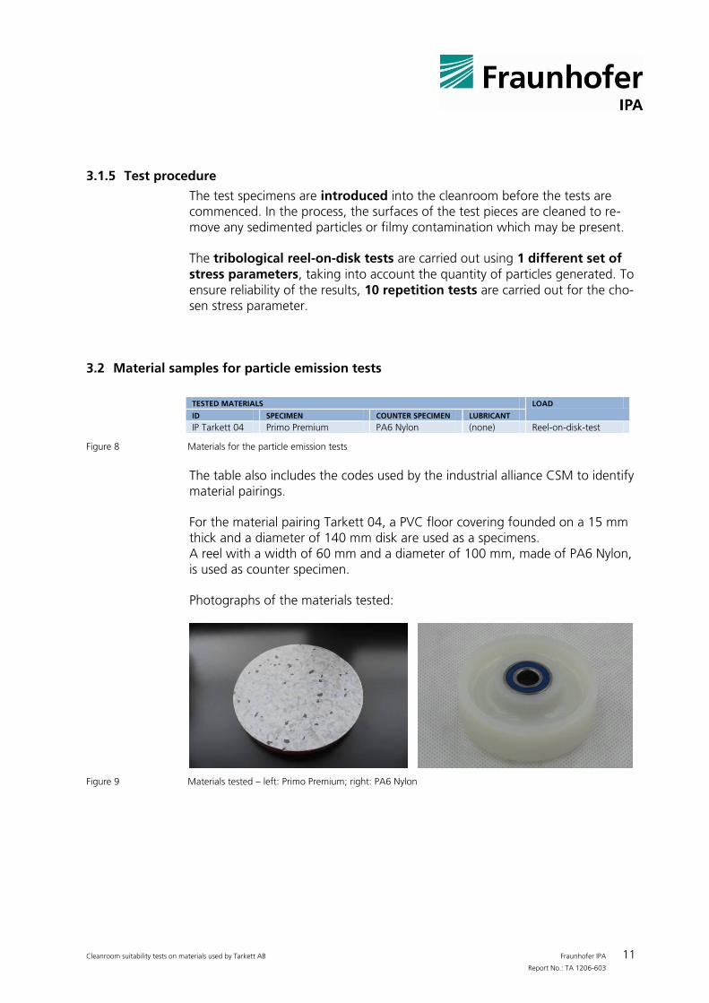
3.2 Material samples for particle emission tests
TESTED MATERIALS LOAD
ID SPECIMEN COUNTER SPECIMEN LUBRICANT
IP Tarkett 04 Primo Premium PA6 Nylon (none) Reel-on-disk-test
Figure 8 Materials for the particle emission tests
The table also includes the codes used by the industrial alliance CSM to identify material pairings.
For the material pairing Tarkett 04, a PVC floor covering founded on a 15 mm thick and a diameter of 140 mm disk are used as a specimens. A reel with a width of 60 mm and a diameter of 100 mm, made of PA6 Nylon, is used as counter specimen.
Photographs of the materials tested:
Figure 9 Materials tested – left: Primo Premium; right: PA6 Nylon
Cleanroom suitability tests on materials used by Tarkett AB Fraunhofer IPA 12 Report No.: TA 1206-603
3.3 Particle emission results
3.3.1 Differential progression of particle emission
3.3.1.1 Method
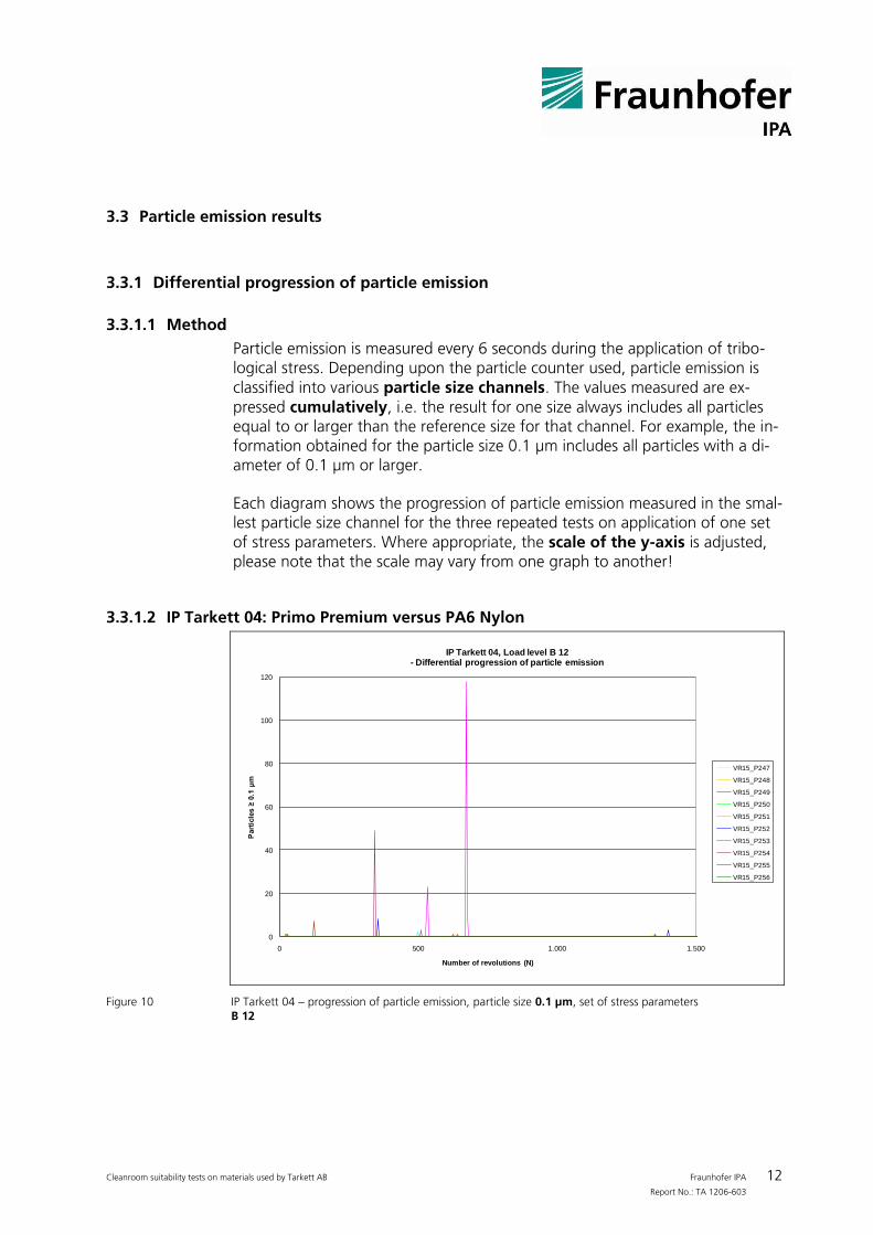
Particle emission is measured every 6 seconds during the application of tribo-logical stress. Depending upon the particle counter used, particle emission is classified into various particle size channels. The values measured are ex-pressed cumulatively, i.e. the result for one size always includes all particles equal to or larger than the reference size for that channel. For example, the in-formation obtained for the particle size 0.1 µm includes all particles with a di-ameter of 0.1 µm or larger.
Each diagram shows the progression of particle emission measured in the smal-lest particle size channel for the three repeated tests on application of one set of stress parameters. Where appropriate, the scale of the y-axis is adjusted, please note that the scale may vary from one graph to another!
3.3.1.2 IP Tarkett 04: Primo Premium versus PA6 Nylon
0
20
40
60
80
100
120
0 500 1.000 1.500
Part
icle
s ≥
0.1
µm
Number of revolutions (N)
IP Tarkett 04, Load level B 12 - Differential progression of particle emission
VR15_P247
VR15_P248
VR15_P249
VR15_P250
VR15_P251
VR15_P252
VR15_P253
VR15_P254
VR15_P255
VR15_P256
Figure 10 IP Tarkett 04 – progression of particle emission, particle size 0.1 µm, set of stress parameters
B 12
Cleanroom suitability tests on materials used by Tarkett AB Fraunhofer IPA 13 Report No.: TA 1206-603
3.3.2 Size distribution of the emitted particles
3.3.2.1 Method
From the particle emission progression data, the percentage of each particle size in relation to the total count of emitted particles is calculated. If, for ex-ample, the particle sizes 0.1 µm, 0.2 µm, 0.3 µm, 0.5 µm, 1.0 µm and 5.0 µm are recorded by the optical particle counter, the percentage of the
Particles in the size channel 0.1 µm relates to particles with a diameter of 0.1 µm to 0.2 µm,
Particles in the size channel 0.2 µm relates to particles with a diameter of 0.2 µm to 0.3 µm,
Particles in the size channel 0.3 µm relates to particles with a diameter of 0.3 µm to 0.5 µm,
Particles in the size channel 0.5 µm relates to particles with a diameter of 0.5 µm to 1.0 µm,
Particles in the size channel 1.0 µm relates to particles with a diameter of 1.0 µm to 5.0µm,
Particles in the size channel 5.0 µm relates to particles with a diameter equal to or greater than 5.0µm.
Values are obtained from all three repeated tests. The size channel stated is dependent upon the optical particle counter used in the tests.
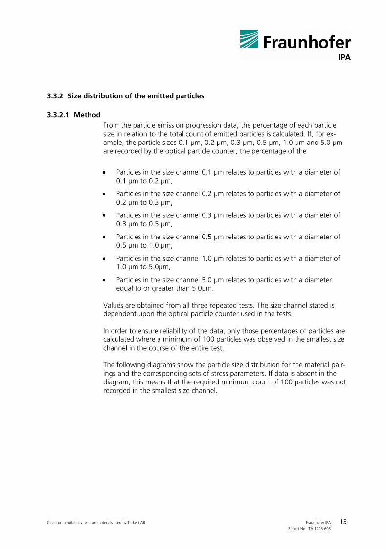
In order to ensure reliability of the data, only those percentages of particles are calculated where a minimum of 100 particles was observed in the smallest size channel in the course of the entire test.
The following diagrams show the particle size distribution for the material pair-ings and the corresponding sets of stress parameters. If data is absent in the diagram, this means that the required minimum count of 100 particles was not recorded in the smallest size channel.
Cleanroom suitability tests on materials used by Tarkett AB Fraunhofer IPA 14 Report No.: TA 1206-603
3.3.2.2 IP Tarkett 04: Primo Premium versus PA6 Nylon
B 12
5.0 µm
1.0 µm
0.5 µm
0.3 µm
0.2 µm
0.1 µm
0%
10%
20%
30%
40%
50%
60%
70%
80%
90%
100%
Perc
en
tag
eIP Tarkett 04 -
Percentage of particle sizes in relation to total count of emitted particles
Figure 11 IP Tarkett 04– Size distribution of the emitted particles (required minimum count of 100 particles was not
recorded)
3.3.3 Classification
3.3.3.1 Method
In general, airborne particulate contamination is the main issue considered when assessing cleanroom suitability. The most important aspects of this are the size and concentration of airborne particles. Relevant standards state limit-ing values for the concentration of airborne particles in dependence upon par-ticle size, as found in ISO 14644-1. This norm describes the quality of clean-rooms using Air Cleanliness Classes ranging from 1 to 9. The lowest class, Class 1, fulfills the highest requirements with regard to air cleanliness; the lim-iting value of particles permitted increases with each successive cleanroom class. Calculations can be made for limiting values of any particle size between 0.1 µm and 5.0 µm for all classes using the method for calculating permitted limiting values as described in ISO 14644-1. The norm states the maximum permitted number of particles of each size for the reference volume (in this case: 1 m3).
The tests performed record particle emissions generated when tribological stress is applied to material pairings. The amounts of particles measured are dependent upon the material pairing concerned and the set of stress parame-ters applied. In order to better appreciate the differences, Fraunhofer IPA has developed a method which enables classifications to be made based on the measurement results obtained using the procedure stated in ISO 14644-1.
MP1
bis
Cleanroom suitability tests on materials used by Tarkett AB Fraunhofer IPA 15 Report No.: TA 1206-603
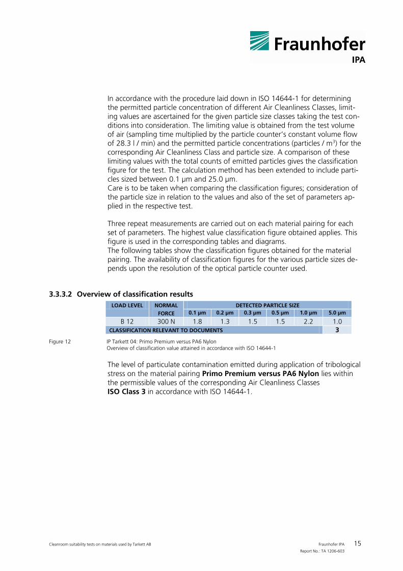
In accordance with the procedure laid down in ISO 14644-1 for determining the permitted particle concentration of different Air Cleanliness Classes, limit-ing values are ascertained for the given particle size classes taking the test con-ditions into consideration. The limiting value is obtained from the test volume of air (sampling time multiplied by the particle counter’s constant volume flow of 28.3 l / min) and the permitted particle concentrations (particles / m3) for the corresponding Air Cleanliness Class and particle size. A comparison of these limiting values with the total counts of emitted particles gives the classification figure for the test. The calculation method has been extended to include parti-cles sized between 0.1 µm and 25.0 µm. Care is to be taken when comparing the classification figures; consideration of the particle size in relation to the values and also of the set of parameters ap-plied in the respective test.
Three repeat measurements are carried out on each material pairing for each set of parameters. The highest value classification figure obtained applies. This figure is used in the corresponding tables and diagrams. The following tables show the classification figures obtained for the material pairing. The availability of classification figures for the various particle sizes de-pends upon the resolution of the optical particle counter used.
3.3.3.2 Overview of classification results
LOAD LEVEL NORMAL
FORCE DETECTED PARTICLE SIZE
0.1 µm 0.2 µm 0.3 µm 0.5 µm 1.0 µm 5.0 µm
B 12 300 N 1.8 1.3 1.5 1.5 2.2 1.0 CLASSIFICATION RELEVANT TO DOCUMENTS 3
Figure 12 IP Tarkett 04: Primo Premium versus PA6 Nylon
Overview of classification value attained in accordance with ISO 14644-1
The level of particulate contamination emitted during application of tribological stress on the material pairing Primo Premium versus PA6 Nylon lies within the permissible values of the corresponding Air Cleanliness Classes ISO Class 3 in accordance with ISO 14644-1.
Cleanroom suitability tests on materials used by Tarkett AB Fraunhofer IPA 16 Report No.: TA 1206-603
1
2
3
0,1 0,2 0,3 0,5 0,7 1,0 5,0
Cla
ssif
icati
on
in
acc
ord
an
ce t
o I
SO
14644-1
Particle size [µm]
IP Tarket 04 -Classification regarding the load level and particle size
B 12
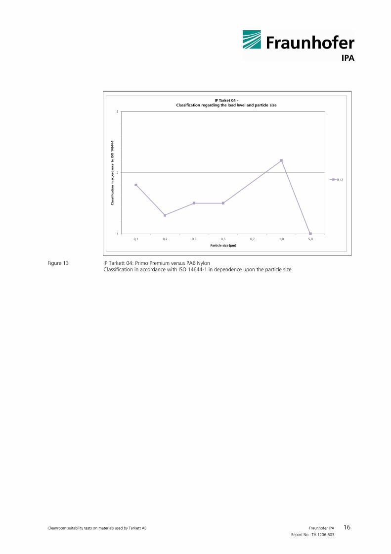
Figure 13 IP Tarkett 04: Primo Premium versus PA6 Nylon
Classification in accordance with ISO 14644-1 in dependence upon the particle size
MP1
bis
Cleanroom suitability tests on materials used by Tarkett AB Fraunhofer IPA 17 Report No.: TA 1206-603
3.4 Comparison of Classifications of Airborne Particulate Contamination
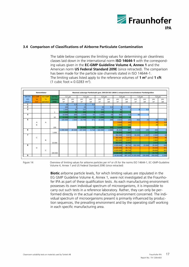
The table below compares the limiting values for determining air cleanliness classes laid down in the international norm ISO 14644-1 with the correspond-ing values given in the EC-GMP Guideline Volume 4, Annex 1 and the American norm US Federal Standard 209E (since retracted). The comparison has been made for the particle size channels stated in ISO 14644-1. The limiting values listed apply to the reference volumes of 1 m3 and 1 cft (1 cubic foot = 0.0283 m3).
DIN EN EG-GMP EG-GMP US Fed.
ISO "at "in Standard pro pro pro pro pro pro pro pro pro pro pro pro
14644-1 rest" operation" 209E* m³ cbf m³ cbf m³ cbf m³ cbf m³ cbf m³ cbf
1 10 0,3 2 0,1
2 100 3 24 1 10 0,3 4 0,1
1.000 30 237 7 102 3 35 1 8 0,2
1 1.240 35 265 8 106 3 35 1
10.000 300 2.370 67 1.020 29 352 9,9 83 2
10 12.000 340 2.650 75 1.060 29 353 10
100.000 2.833 23.700 671 10.200 289 3.520 100 832 24 29 0,8
A A 3.520 100 20 0,6
B 3.520 100 29 0,8
100 26.500 750 10.600 300 3.530 100
1.000.000 28.329 237.000 6.710 102.000 2.890 35.200 997 8.320 235 293 8
1.000 35.300 1.000 247 7
352.000 9.972 83.200 2.357 2.930 83
C 352.000 9.972 2.900 82
B 352.000 9.972 2.900 82
10.000 353.000 10.000 2.470 70
3.520.000 99.716 832.000 23.569 29.300 830
D 3.520.000 99.716 29.000 821
C 3.520.000 99.716 29.000 821
100.000 3.530.000 100.000 24.700 700
9 35.200.000 997.167 8.320.000 235.694 293.000 8.300
7
8
3
4
5
6
5,0 μm
Maximal zulässige Partikelzahl gem. DIN EN ISO 14644-1 entsprechend verschiedener Partikelgrößen
0,1 μm 0,3 μm
Nomenklatur
0,2 μm 0,5 μm 1,0 μm
Figure 14 Overview of limiting values for airborne particles per m³ or cft for the norms ISO 14644-1, EC-GMP-Guideline
Volume 4, Annex 1 and US Federal Standard 209E (since retracted)
Biotic airborne particle levels, for which limiting values are stipulated in the EG GMP Guideline Volume 4, Annex 1, were not investigated at the Fraunho-fer IPA as part of these qualification tests. As each manufacturing environment possesses its own individual spectrum of microorganisms, it is impossible to carry out such tests in a reference laboratory. Rather, they can only be per-formed directly in the actual manufacturing environment concerned. The indi-vidual spectrum of microorganisms present is primarily influenced by produc-tion sequences, the prevailing environment and by the operating staff working in each specific manufacturing area.
Cleanroom suitability tests on materials used by Tarkett AB Fraunhofer IPA 18 Report No.: TA 1206-603
4 Outgassing tests under thermal stress
4.1 Material samples
The material samples required for the test were supplied by the customer. Tests were carried out on the following materials.
TESTED MATERIALS
OUTGASSING TEMPERATURES TESTED TESTED FOR
NAME (SHORT FORM) 23°C/73 °F 90°C/194 °F
PRIMO PREMIUM X X VOC
Figure 15 Material samples tested for outgassing
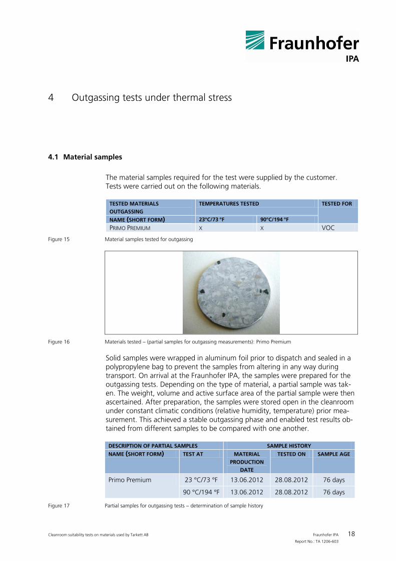
Figure 16 Materials tested – (partial samples for outgassing measurements): Primo Premium
Solid samples were wrapped in aluminum foil prior to dispatch and sealed in a polypropylene bag to prevent the samples from altering in any way during transport. On arrival at the Fraunhofer IPA, the samples were prepared for the outgassing tests. Depending on the type of material, a partial sample was tak-en. The weight, volume and active surface area of the partial sample were then ascertained. After preparation, the samples were stored open in the cleanroom under constant climatic conditions (relative humidity, temperature) prior mea-surement. This achieved a stable outgassing phase and enabled test results ob-tained from different samples to be compared with one another.
DESCRIPTION OF PARTIAL SAMPLES SAMPLE HISTORY NAME (SHORT FORM) TEST AT MATERIAL
PRODUCTION
DATE
TESTED ON SAMPLE AGE
Primo Premium 23 °C/73 °F 13.06.2012 28.08.2012 76 days
90 °C/194 °F 13.06.2012 28.08.2012 76 days
Figure 17 Partial samples for outgassing tests – determination of sample history
Cleanroom suitability tests on materials used by Tarkett AB Fraunhofer IPA 19 Report No.: TA 1206-603
DESCRIPTION OF PARTIAL SAMPLES SAMPLE CHARACTERISTICS NAME (SHORT FORM) TEST AT SURFACE
[m2] MASS
[g] VOLUME
[m3]
Primo Premium 23°C/73 °F 0.001 4.15 2.0 x 10⁻⁶
90°C/194 °F 0.001 4.15 2.0 x 10⁻⁶
Figure 18 Partial samples for outgassing tests – determination of sample characteristics
4.2 Outgassing test procedure
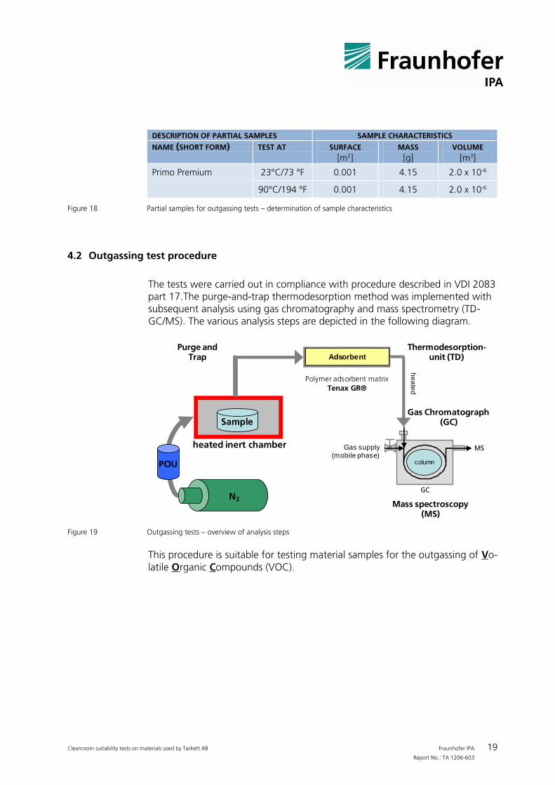
The tests were carried out in compliance with procedure described in VDI 2083 part 17.The purge-and-trap thermodesorption method was implemented with subsequent analysis using gas chromatography and mass spectrometry (TD-GC/MS). The various analysis steps are depicted in the following diagram.
Mass spectroscopy (MS)
Trägergas Einlass
Trägergas Auslass
Probengefäß
Probe
Probenträger
He
izm
an
tel
Probenahme: apparativer Aufbau
Gasversorgung
(Mobile Phase)
GC
MSSäule
Adsorbens: T1 bzw. T2
Cryo Purge & Trap
TENAX TA
beheizt
beh
eiz
t
Sample
heated inert chamber
N2
POU
Purge and Trap
Thermodesorption-unit (TD)
Gas Chromatograph (GC)
Polymer adsorbent matrix
Tenax GR®
Adsorbent
Gas supply (mobile phase)
he
ate
d
column
Figure 19 Outgassing tests – overview of analysis steps
This procedure is suitable for testing material samples for the outgassing of Vo-latile Organic Compounds (VOC).
Cleanroom suitability tests on materials used by Tarkett AB Fraunhofer IPA 20 Report No.: TA 1206-603
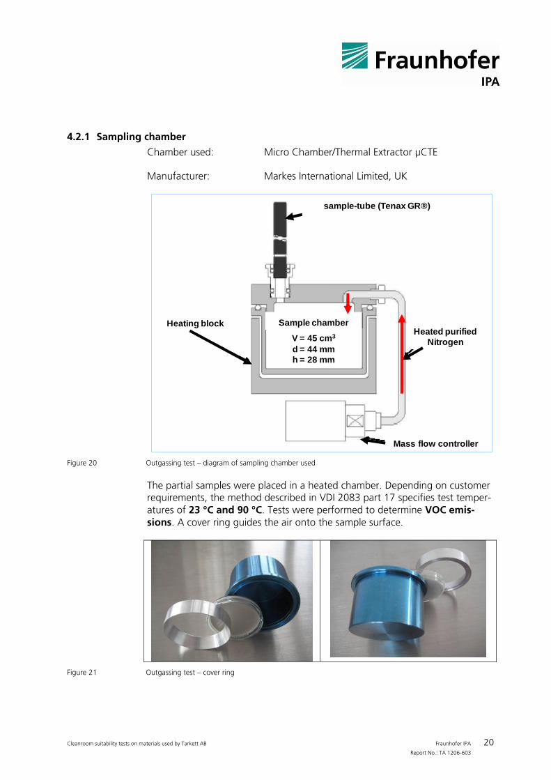
4.2.1 Sampling chamber
Chamber used: Micro Chamber/Thermal Extractor µCTE
Manufacturer: Markes International Limited, UK
Sample chamber
V = 45 cm3
d = 44 mm
h = 28 mm
sample-tube (Tenax GR®)
Heating block
Mass flow controller
Heated purified
Nitrogen
Figure 20 Outgassing test – diagram of sampling chamber used
The partial samples were placed in a heated chamber. Depending on customer requirements, the method described in VDI 2083 part 17 specifies test temper-atures of 23 °C and 90 °C. Tests were performed to determine VOC emis-sions. A cover ring guides the air onto the sample surface.
Figure 21 Outgassing test – cover ring
Cleanroom suitability tests on materials used by Tarkett AB Fraunhofer IPA 21 Report No.: TA 1206-603
During the test, each partial sample was heated to the test temperature which caused it to emit volatile organic substances (VOC outgassing). By introducing ultra-clean air, the substances present in the chamber were displaced and guided into an adsorber tube (purging). The substances were “trapped” by the adsorbent material present in the tube and the (now re-purified) rinsing air exited at the outlet of the tube.
On completion of the test, all substances emitted by the sample were fixed in adsorbed form in the polymer matrix in the tube. The tube was then sealed and transferred for analysis. The adsorber tube utilized in the tests was a stain-less steel tube 90 mm long and 6.35 mm in diameter containing 200 mg Tenax TA®. The polymer adsorber matrix Tenax TA® is suitable for trapping C6 to C40 hydrocarbons. This equates with TVOC tests = Total Volatile Organic Com-pounds = absolute quantity of all volatile organic compounds.
Ultra-pure nitrogen was used as a rinsing gas and was additionally filtered by an active charcoal filter before entering the chamber. Before commencing the tests, the chamber was rinsed for 5 min in order to remove any reactive gases which may have been present. The rinsing gas was fed through the chamber at a rate of 100 ml/min, i.e. the complete chamber volume was re-placed approx ten times. By rinsing the chamber continuously, a balance be-tween substances still contained in the sample and substances already in the gas phase can be avoided. This equates with conditions experienced by com-ponents in a cleanroom in reality.
After the 5 min pre-rinse, the standard sampling time of 60 min at 23° C and 10 min at 90 °C was used. The carrier gas exiting from the chamber which contained the VOCs to be detected was then fed into the adsorber tube.
To determine the blank value of the system, the complete sampling proce-dure was carried out before commencing the tests without the presence of a sample in the chamber. This meant that the only variable in the entire analysis was the introduction of a sample into the chamber. The blank values of the various substances detected were then subtracted from the subsequent sample values obtained in order to ascertain absolute values for the components out-gassed.
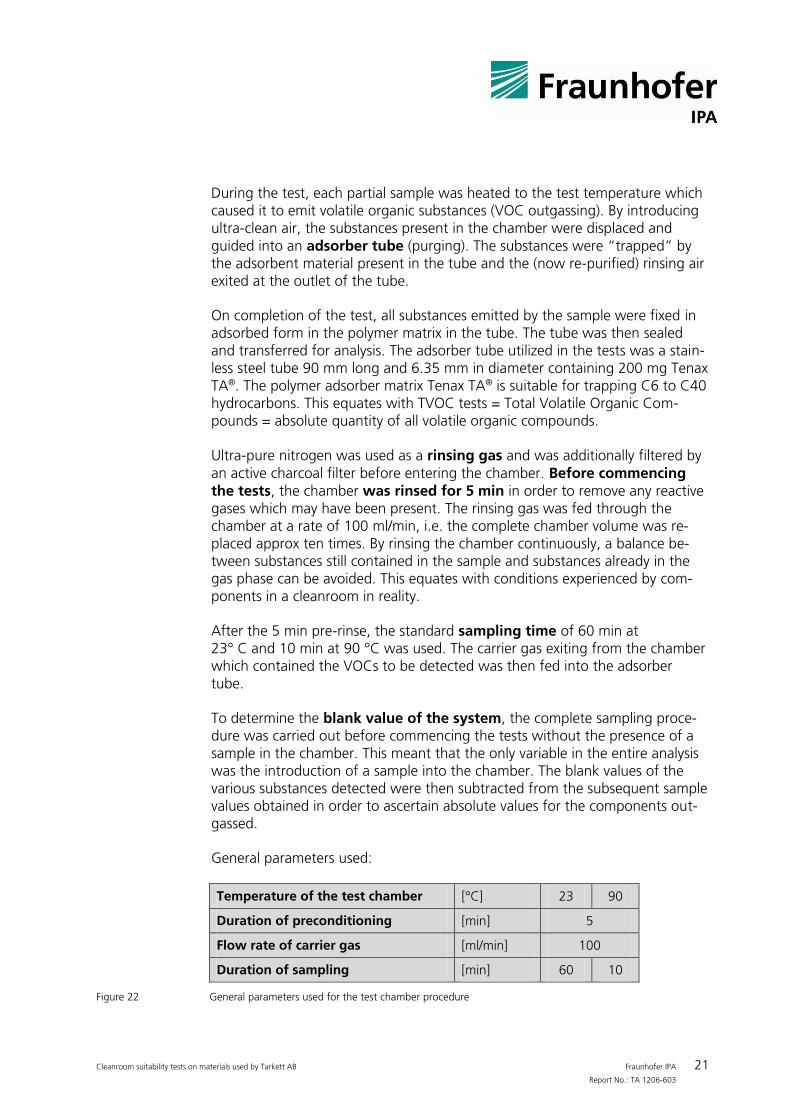
General parameters used:
Temperature of the test chamber [°C] 23 90
Duration of preconditioning [min] 5
Flow rate of carrier gas [ml/min] 100
Duration of sampling [min] 60 10
Figure 22 General parameters used for the test chamber procedure
Cleanroom suitability tests on materials used by Tarkett AB Fraunhofer IPA 22 Report No.: TA 1206-603
4.2.2 Analysis devices
The adsorber tube containing all the outgassed substances was then analyzed using a combined TD-GC/MS unit (thermodesorption gas chromatography in combination with mass spectroscopy).
The tubes were heated for a short period of time to enable the substances trapped in the adsorber matrix to be released (thermodesorption). These were then guided into the measuring unit. Gas chromatography was used to sepa-rate the substances present in the mixture. The individual substances reached the attached mass spectrometer at different moments in time and were de-tected.
The following measuring devices were implemented in the test:
GC/MS: a) GC: PerkinElmer Clarus 600 b) MS: PerkinElmer Clarus 600T
Thermodesorber: PerkinElmer Turbomatrix ATD 650
Column: PerkinElmer Elite 5 - MS, l = 60 m, ID = 0.25 mm, film = 0.25 µm

Cleanroom suitability tests on materials used by Tarkett AB Fraunhofer IPA 23 Report No.: TA 1206-603
4.3 Outgassing results
The following results were obtained from the tests performed.
Determination of the qualitative VOC spectrum
Quantitative determination of the components outgassed (based on tolu-ene equivalents),
Quantitative determination of TVOC values (based on toluene equivalents),
Relevant comments concerning contaminants critical to cleanroom envi-ronments
Classification in accordance with VDI 2083 part 17
The qualitative VOC spectra were ascertained based on the chromatograms obtained from the gas chromatography tests and the mass spectrograms from the mass spectrometer. Each separate substance possesses a characteristic retention period in chroma-tographs as well as a characteristic fragmentation in the mass spectrometer. This information is filed in appropriate databases. Substances can be identified by comparing the retention times and fragments observed in the test with those listed in the databases. Each chromatogram shows the chronological or-der of each substance detected.
Note: Due to test-related fluctuations, the information obtained concerning the iden-tities of the substances detected is associated with a certain degree of uncer-tainty. As a rule, the substance named is the one which has the highest proba-bility of being the substance which was outgassed. If a detected substance cannot be ascertained, the substance is labeled “n. i.” (=not identifiable) in the table. If a substance cannot be identified with certainty, the substance is marked in the table with a question mark (“?“).
By using a reference substance (hexadecane) in a known concentration parallel to the tests, the concentration of each substance identified can be ascertained as a toluene equivalent (quantitative analysis based on toluene equiva-lents). The quantities of substances detected have been documented in rela-tion to the mass, volume and weight of the partial samples.
4.4 Classification
The classification is based on the guideline VDI 2083 part 17. The material-specific Classification (ISO-AMCm class) is calculated as decanal logarithm of the determined surface-specific emission rate SERa, which is advance normed with the SI-values of 1 m2 surface area, 1 m3 compartment volume and one second
Cleanroom suitability tests on materials used by Tarkett AB Fraunhofer IPA 24 Report No.: TA 1206-603
to the value TVOCnorm. By using logarithmic calculus, the ISO-AMCm classes fea-ture all negative values with the result that permissible concentrations decrease as quantities increase. Therefore, ISO-AMCm Class -12 equates to a limiting value 1000 times lower than ISO-AMCm Class -9.
The classification figure ISO-AMCm-Class obtained states that 1 m2 of the test material emits a quantity of the given substance class over the space of 1 s at the test temperature which, when related to the reference volume of 1 m3, is within the permissible concentration for this class as laid down in ISO 14644-8. To do this, the reference volume is to be viewed statistically and may not be exchanged, thus enabling the values obtained to be converted to real clea-nrooms also addressed in VDI 2083 part 17.
Remark: ISO 14644-8 addresses the classification of cleanrooms based on the concentration of certain groups of contaminants (ISO-AMC-classes). The con-taminant groups can be organics (or), acids (ac), bases (ba), dopants (dp) or others and are expressed with the corresponding descriptor.
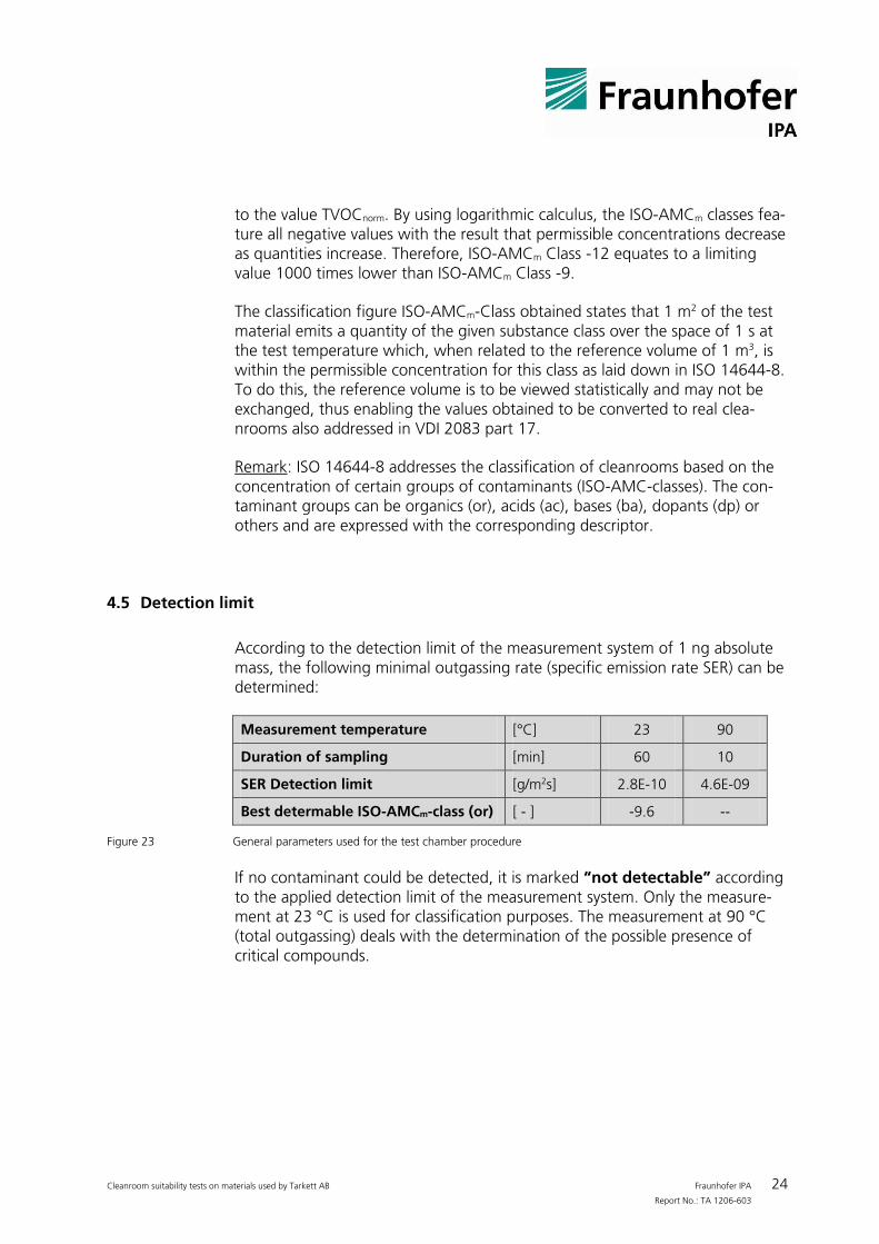
4.5 Detection limit
According to the detection limit of the measurement system of 1 ng absolute mass, the following minimal outgassing rate (specific emission rate SER) can be determined:
Measurement temperature [°C] 23 90
Duration of sampling [min] 60 10
SER Detection limit [g/m2s] 2.8E-10 4.6E-09
Best determable ISO-AMCm-class (or) [ - ] -9.6 --
Figure 23 General parameters used for the test chamber procedure
If no contaminant could be detected, it is marked “not detectable” according to the applied detection limit of the measurement system. Only the measure-ment at 23 °C is used for classification purposes. The measurement at 90 °C (total outgassing) deals with the determination of the possible presence of critical compounds.
Cleanroom suitability tests on materials used by Tarkett AB Fraunhofer IPA 25 Report No.: TA 1206-603
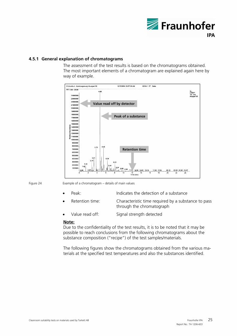
4.5.1 General explanation of chromatograms
The assessment of the test results is based on the chromatograms obtained. The most important elements of a chromatogram are explained again here by way of example.
Retention time
SI - Similarity factor
Mass spectrogramof compound detected
Mass spectrogramof compound in device
library
Differential diagramfrom both diagrams
on the left
Compound in detail:• Molecular weight• CAS-Number• Empirical formula
RSI - Similarity factor
Peak of a substance
Value read off by detector
Figure 24 Example of a chromatogram – details of main values
Peak: Indicates the detection of a substance
Retention time: Characteristic time required by a substance to pass through the chromatograph
Value read off: Signal strength detected
Note: Due to the confidentiality of the test results, it is to be noted that it may be possible to reach conclusions from the following chromatograms about the substance composition (“recipe”) of the test samples/materials.
The following figures show the chromatograms obtained from the various ma-terials at the specified test temperatures and also the substances identified.
Cleanroom suitability tests on materials used by Tarkett AB Fraunhofer IPA 26 Report No.: TA 1206-603
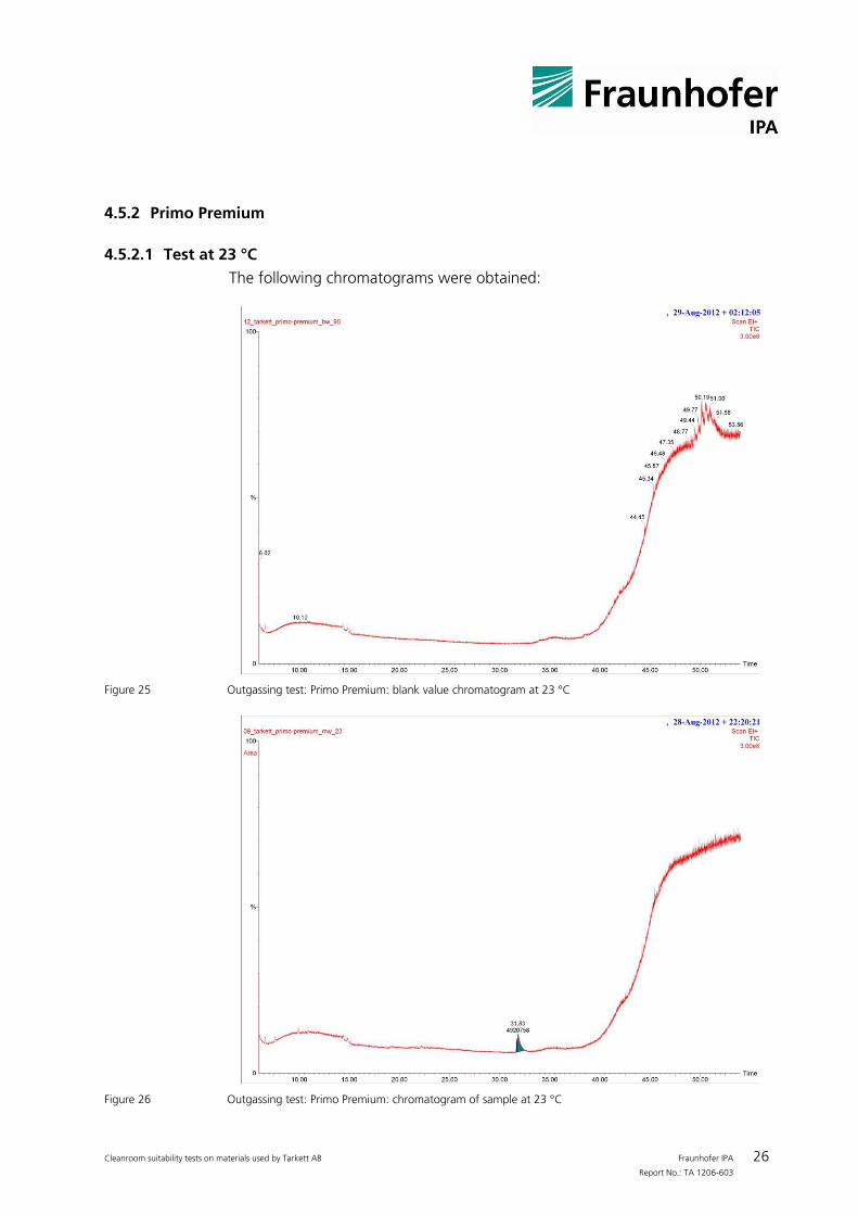
4.5.2 Primo Premium
4.5.2.1 Test at 23 °C
The following chromatograms were obtained:
Figure 25 Outgassing test: Primo Premium: blank value chromatogram at 23 °C
Figure 26 Outgassing test: Primo Premium: chromatogram of sample at 23 °C
Cleanroom suitability tests on materials used by Tarkett AB Fraunhofer IPA 27 Report No.: TA 1206-603
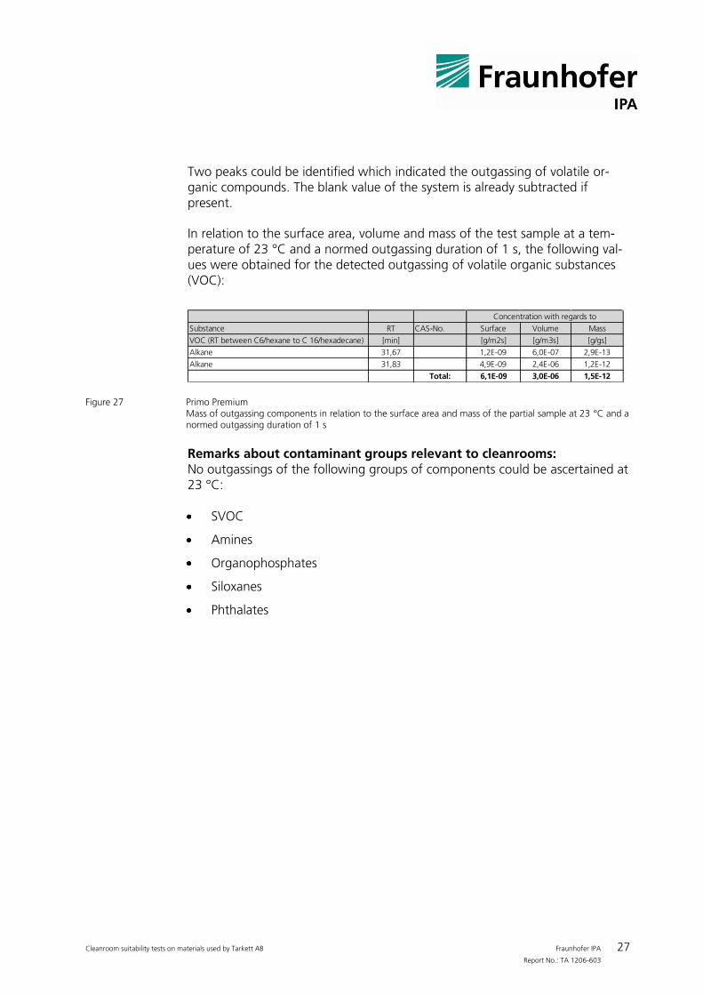
Two peaks could be identified which indicated the outgassing of volatile or-ganic compounds. The blank value of the system is already subtracted if present.
In relation to the surface area, volume and mass of the test sample at a tem-perature of 23 °C and a normed outgassing duration of 1 s, the following val-ues were obtained for the detected outgassing of volatile organic substances (VOC):
Substance RT CAS-No. Surface Volume Mass
VOC (RT between C6/hexane to C 16/hexadecane) [min] [g/m2s] [g/m3s] [g/gs]
Alkane 31,67 1,2E-09 6,0E-07 2,9E-13
Alkane 31,83 4,9E-09 2,4E-06 1,2E-12
Total: 6,1E-09 3,0E-06 1,5E-12
Concentration with regards to
Figure 27 Primo Premium
Mass of outgassing components in relation to the surface area and mass of the partial sample at 23 °C and a
normed outgassing duration of 1 s
Remarks about contaminant groups relevant to cleanrooms: No outgassings of the following groups of components could be ascertained at 23 °C:
SVOC
Amines
Organophosphates
Siloxanes
Phthalates
Cleanroom suitability tests on materials used by Tarkett AB Fraunhofer IPA 28 Report No.: TA 1206-603
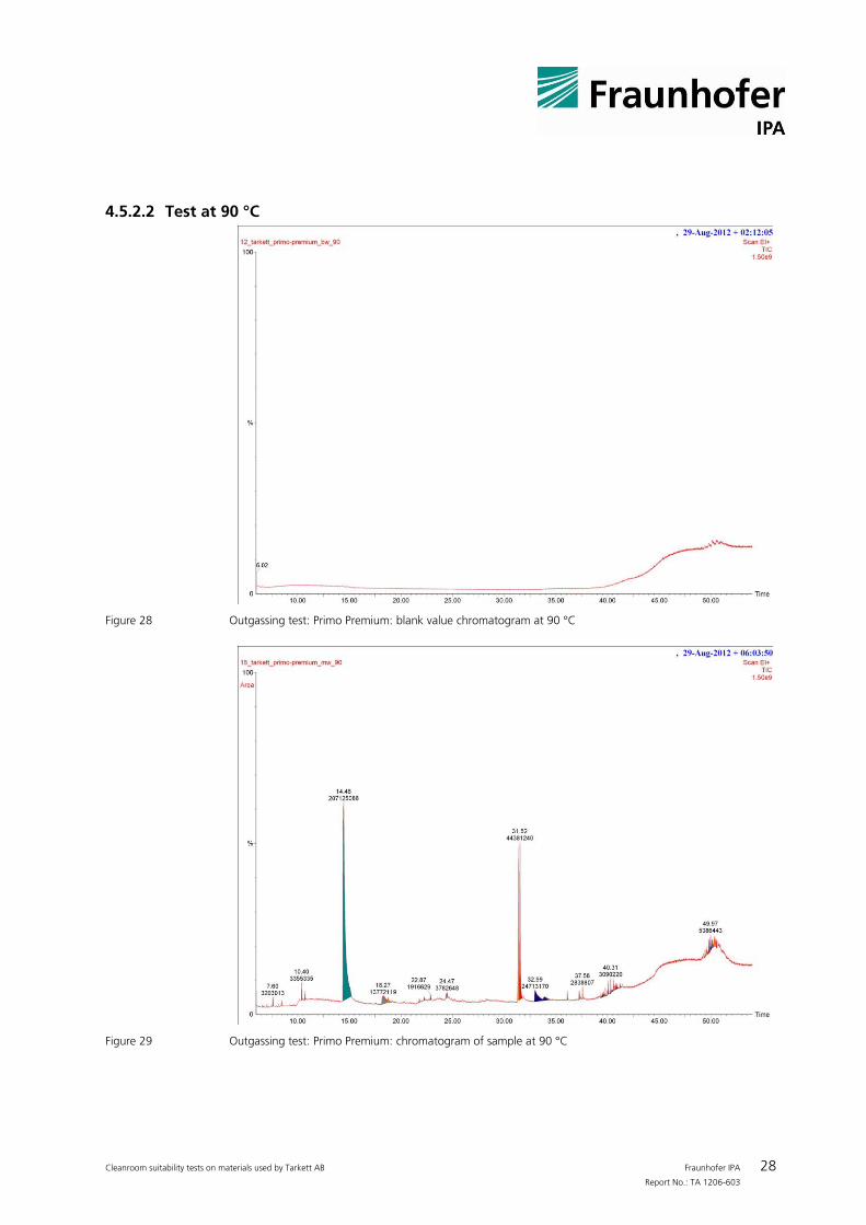
4.5.2.2 Test at 90 °C
Figure 28 Outgassing test: Primo Premium: blank value chromatogram at 90 °C
Figure 29 Outgassing test: Primo Premium: chromatogram of sample at 90 °C
Cleanroom suitability tests on materials used by Tarkett AB Fraunhofer IPA 29 Report No.: TA 1206-603
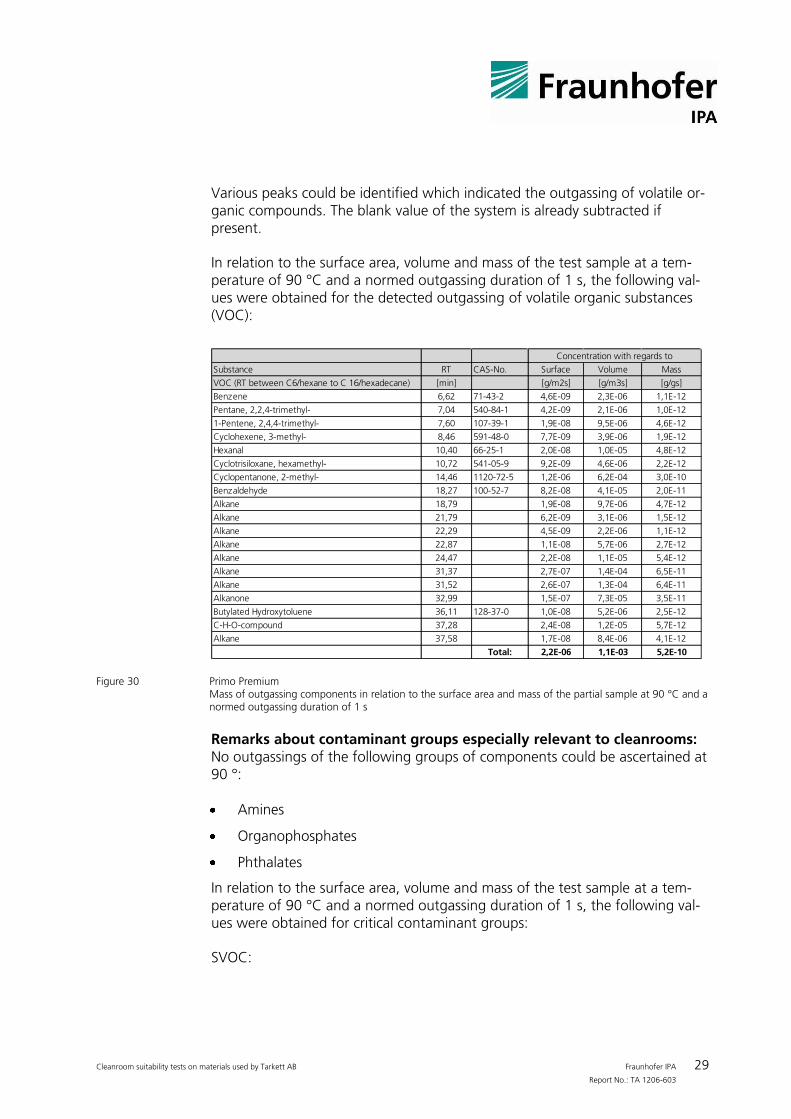
Various peaks could be identified which indicated the outgassing of volatile or-ganic compounds. The blank value of the system is already subtracted if present.
In relation to the surface area, volume and mass of the test sample at a tem-perature of 90 °C and a normed outgassing duration of 1 s, the following val-ues were obtained for the detected outgassing of volatile organic substances (VOC):
Substance RT CAS-No. Surface Volume Mass
VOC (RT between C6/hexane to C 16/hexadecane) [min] [g/m2s] [g/m3s] [g/gs]
Benzene 6,62 71-43-2 4,6E-09 2,3E-06 1,1E-12
Pentane, 2,2,4-trimethyl- 7,04 540-84-1 4,2E-09 2,1E-06 1,0E-12
1-Pentene, 2,4,4-trimethyl- 7,60 107-39-1 1,9E-08 9,5E-06 4,6E-12
Cyclohexene, 3-methyl- 8,46 591-48-0 7,7E-09 3,9E-06 1,9E-12
Hexanal 10,40 66-25-1 2,0E-08 1,0E-05 4,8E-12
Cyclotrisiloxane, hexamethyl- 10,72 541-05-9 9,2E-09 4,6E-06 2,2E-12
Cyclopentanone, 2-methyl- 14,46 1120-72-5 1,2E-06 6,2E-04 3,0E-10
Benzaldehyde 18,27 100-52-7 8,2E-08 4,1E-05 2,0E-11
Alkane 18,79 1,9E-08 9,7E-06 4,7E-12
Alkane 21,79 6,2E-09 3,1E-06 1,5E-12
Alkane 22,29 4,5E-09 2,2E-06 1,1E-12
Alkane 22,87 1,1E-08 5,7E-06 2,7E-12
Alkane 24,47 2,2E-08 1,1E-05 5,4E-12
Alkane 31,37 2,7E-07 1,4E-04 6,5E-11
Alkane 31,52 2,6E-07 1,3E-04 6,4E-11
Alkanone 32,99 1,5E-07 7,3E-05 3,5E-11
Butylated Hydroxytoluene 36,11 128-37-0 1,0E-08 5,2E-06 2,5E-12
C-H-O-compound 37,28 2,4E-08 1,2E-05 5,7E-12
Alkane 37,58 1,7E-08 8,4E-06 4,1E-12
Total: 2,2E-06 1,1E-03 5,2E-10
Concentration with regards to
Figure 30 Primo Premium
Mass of outgassing components in relation to the surface area and mass of the partial sample at 90 °C and a
normed outgassing duration of 1 s
Remarks about contaminant groups especially relevant to cleanrooms: No outgassings of the following groups of components could be ascertained at 90 °:
Amines
Organophosphates
Phthalates
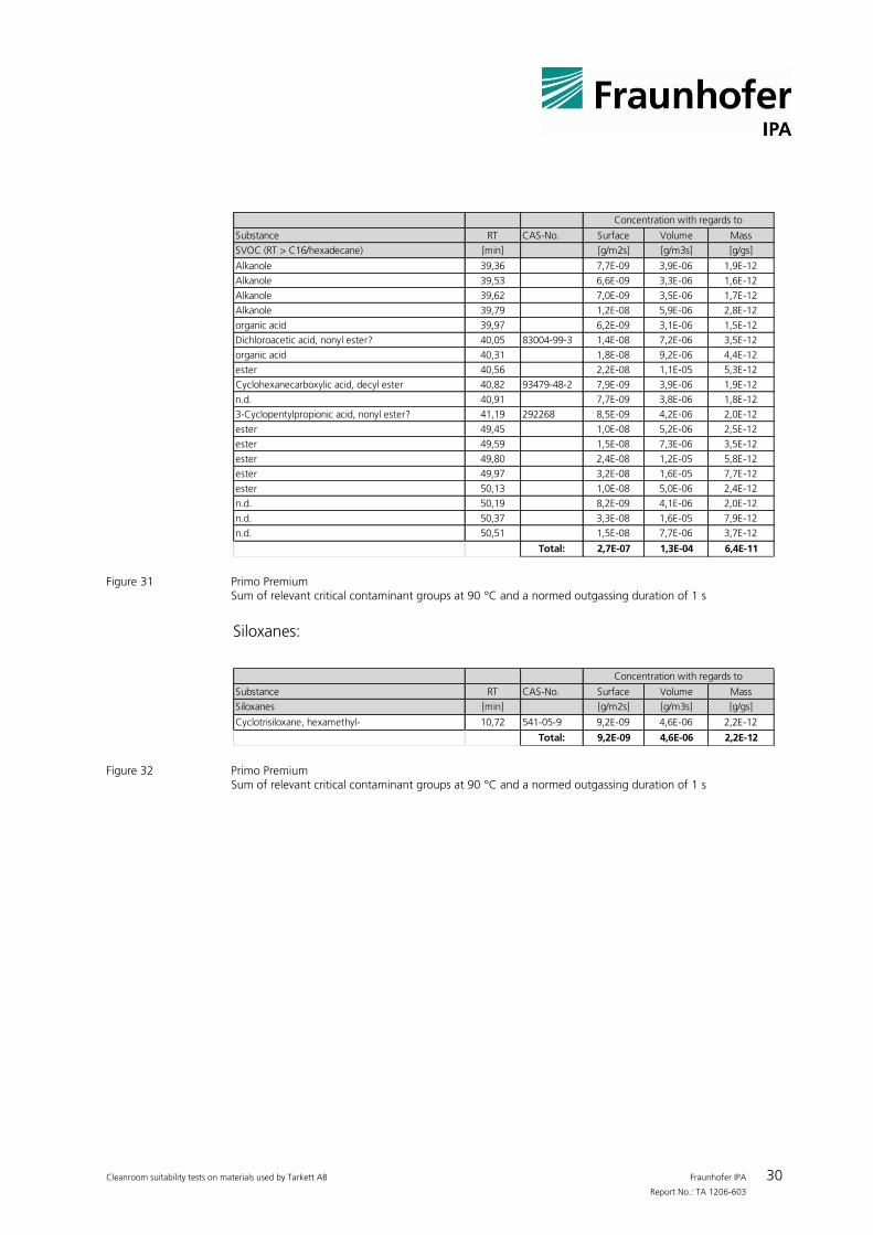
In relation to the surface area, volume and mass of the test sample at a tem-perature of 90 °C and a normed outgassing duration of 1 s, the following val-ues were obtained for critical contaminant groups:
SVOC:
Cleanroom suitability tests on materials used by Tarkett AB Fraunhofer IPA 30 Report No.: TA 1206-603
Substance RT CAS-No. Surface Volume Mass
SVOC (RT > C16/hexadecane) [min] [g/m2s] [g/m3s] [g/gs]
Alkanole 39,36 7,7E-09 3,9E-06 1,9E-12
Alkanole 39,53 6,6E-09 3,3E-06 1,6E-12
Alkanole 39,62 7,0E-09 3,5E-06 1,7E-12
Alkanole 39,79 1,2E-08 5,9E-06 2,8E-12
organic acid 39,97 6,2E-09 3,1E-06 1,5E-12
Dichloroacetic acid, nonyl ester? 40,05 83004-99-3 1,4E-08 7,2E-06 3,5E-12
organic acid 40,31 1,8E-08 9,2E-06 4,4E-12
ester 40,56 2,2E-08 1,1E-05 5,3E-12
Cyclohexanecarboxylic acid, decyl ester 40,82 93479-48-2 7,9E-09 3,9E-06 1,9E-12
n.d. 40,91 7,7E-09 3,8E-06 1,8E-12
3-Cyclopentylpropionic acid, nonyl ester? 41,19 292268 8,5E-09 4,2E-06 2,0E-12
ester 49,45 1,0E-08 5,2E-06 2,5E-12
ester 49,59 1,5E-08 7,3E-06 3,5E-12
ester 49,80 2,4E-08 1,2E-05 5,8E-12
ester 49,97 3,2E-08 1,6E-05 7,7E-12
ester 50,13 1,0E-08 5,0E-06 2,4E-12
n.d. 50,19 8,2E-09 4,1E-06 2,0E-12
n.d. 50,37 3,3E-08 1,6E-05 7,9E-12
n.d. 50,51 1,5E-08 7,7E-06 3,7E-12
Total: 2,7E-07 1,3E-04 6,4E-11
Concentration with regards to
Figure 31 Primo Premium
Sum of relevant critical contaminant groups at 90 °C and a normed outgassing duration of 1 s
Siloxanes:
Substance RT CAS-No. Surface Volume Mass
Siloxanes [min] [g/m2s] [g/m3s] [g/gs]
Cyclotrisiloxane, hexamethyl- 10,72 541-05-9 9,2E-09 4,6E-06 2,2E-12
Total: 9,2E-09 4,6E-06 2,2E-12
Concentration with regards to
Figure 32 Primo Premium
Sum of relevant critical contaminant groups at 90 °C and a normed outgassing duration of 1 s
Cleanroom suitability tests on materials used by Tarkett AB Fraunhofer IPA 31 Report No.: TA 1206-603
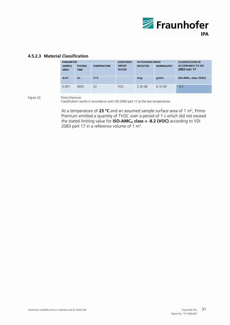
4.5.2.3 Material Classification
PARAMETER SUBSTANCE
GROUP
TESTED
OUTGASSING MASS CLASSIFICATION IN
ACCORDANCE TO VDI
2083 PART 17 SAMPLE
AREA TESTING
TIME TEMPERATURE DETECTED NORMALIZED
A/m2 t/s T/°C m/g g/m²s ISO-AMCm class (VOC)
0.001 3600 23 VOC 2.2E-08 6.1E-09 -8.2
Figure 33 Primo Premium
Classification results in accordance with VDI 2083 part 17 at the test temperatures
At a temperature of 23 °C and an assumed sample surface area of 1 m2, Primo Premium emitted a quantity of TVOC over a period of 1 s which did not exceed the stated limiting value for ISO-AMCm class = -8.2 (VOC) according to VDI 2083 part 17 in a reference volume of 1 m3.