qg 1435 de gb tr sv 110315.indd - valveexpo.com · Sie bitte der Bedienungsanleitung des Pos ... Be...
24
1435 ePos ® Intelligenter Stellungsregler 1435 ePos ® ORIGINAL QUICK GUIDE DE Stand 11.03.2015 Ab Version 2.0.0.3 Intelligent Positioner QUICK GUIDE GB Status 11.03.2015 From version 2.0.0.3
Transcript of qg 1435 de gb tr sv 110315.indd - valveexpo.com · Sie bitte der Bedienungsanleitung des Pos ... Be...

1435 ePos®
Intelligenter Stellungsregler
1435 ePos®
ORIGINAL QUICK GUIDEDE
Stand 11.03.2015Ab Version 2.0.0.3
Intelligent Positioner
QUICK GUIDEGB
Status 11.03.2015From version 2.0.0.3
1435 ePos®2 / 24
Inhaltsverzeichnis1 Sicherheitshinweise 22 Mechanischer Anbau 22.1 Anbau an Linearantriebe 22.1.1 Vorbereitung des Ventilantriebs 22.1.2 Komplettierung des Weggebers 22.1.3 Anbau des Stellungsreglers 32.2 Anbau an Schwenkantriebe 42.2.1 Vorbereitung des Ventilantriebs 42.2.2 Anbau des Stellungsreglers 52.3 Externer Anbau 52.4 Überprüfung des mechanischen Anbaus 53 Pneumatische Anschlüsse 64 Elektrische Anschlüsse 64.1 Ausführung mit Anschlussklemmen (Standard) 64.2 Ausführung mit Steckverbinder (optional) 75 Automatische Initialisierung 86 Fehlerliste 97 Konfigurieren (C: CONFIG) 107.1 Parametereinstellung neue Regler (ab Software V2.0.0.0) 107.2 Parametereinstellung alte Regler (bis Software V1.3.1.8) 108 Hinweise 119 Parametertabelle 12
1 SicherheitshinweiseDie Sicherheitshinweise entnehmen Sie bitte der Bedienungsanleitung des GEMÜ1435 ePos® auf der beiliegenden CD-ROM. Sollten Sie nicht im Besitz dieser CD-ROM sein, wenden Sie sich bitte an GEMÜ.
2 Mechanischer Anbau
2.1 Anbau an Linearantriebe
2.1.1 Vorbereitung des Ventilantriebs
l Antrieb muss sich in Grundstellung (Antrieb entlüftet) befinden.
l Befindet sich im Antrieb oben eine optische Sichtanzeige (rote Spindel), dann diese herausziehen.
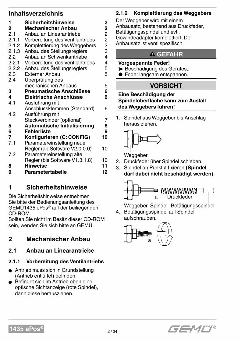
2.1.2 Komplettierung des Weggebers
Der Weggeber wird mit einem Anbausatz, bestehend aus Druckfeder, Betätigungsspindel und evtl. Gewindeadapter komplettiert. Der Anbausatz ist ventilspezifisch.
GEFAHRVorgespannte Feder!
ä Beschädigung des Gerätes,. ● Feder langsam entspannen.
VORSICHTEine Beschädigung der Spindeloberfl äche kann zum Ausfall des Weggebers führen!
1. Spindel aus Weggeber bis Anschlag heraus ziehen.
Weggeber 2. Druckfeder über Spindel schieben. 3. Spindel an Punkt a fixieren (Spindel
darf dabei nicht beschädigt werden).
Weggeber Spindel
a Druckfeder
Betätigungsspindel4. Betätigungsspindel auf Spindel
aufschrauben.
a
1435 ePos®3 / 24
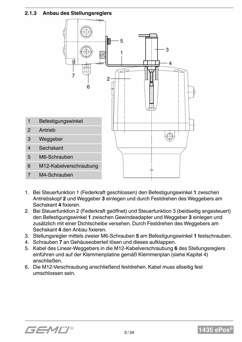
2.1.3 Anbau des Stellungsreglers
5
7
6
2
13
4
1 Befestigungswinkel
2 Antrieb
3 Weggeber
4 Sechskant
5 M6-Schrauben
6 M12-Kabelverschraubung
7 M4-Schrauben
1. Bei Steuerfunktion 1 (Federkraft geschlossen) den Befestigungswinkel 1 zwischen Antriebskopf 2 und Weggeber 3 einlegen und durch Festdrehen des Weggebers am Sechskant 4 fixieren.
2. Bei Steuerfunktion 2 (Federkraft geöffnet) und Steuerfunktion 3 (beidseitig angesteuert) den Befestigungswinkel 1 zwischen Gewindeadapter und Weggeber 3 einlegen und zusätzlich mit einer Dichtscheibe versehen. Durch Festdrehen des Weggebers am Sechskant 4 den Anbau fixieren.
3. Stellungsregler mittels zweier M6-Schrauben 5 am Befestigungswinkel 1 festschrauben.4. Schrauben 7 an Gehäuseoberteil lösen und dieses aufklappen.5. Kabel des Linear-Weggebers in die M12-Kabelverschraubung 6 des Stellungsreglers
einführen und auf der Klemmenplatine gemäß Klemmenplan (siehe Kapitel 4) anschließen.
6. Die M12-Verschraubung anschließend festdrehen. Kabel muss allseitig fest umschlossen sein.
1435 ePos®4 / 24
2.2 Anbau an Schwenkantriebe
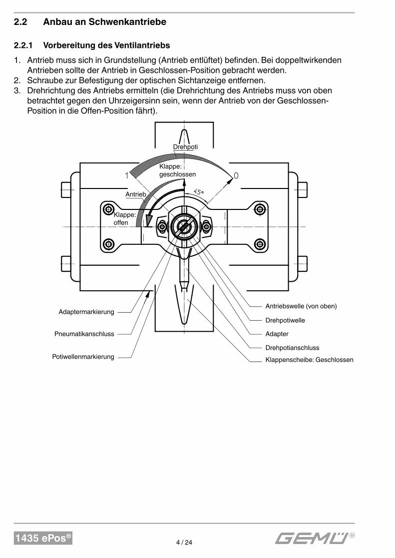
2.2.1 Vorbereitung des Ventilantriebs
1. Antrieb muss sich in Grundstellung (Antrieb entlüftet) befinden. Bei doppeltwirkenden Antrieben sollte der Antrieb in Geschlossen-Position gebracht werden.
2. Schraube zur Befestigung der optischen Sichtanzeige entfernen.3. Drehrichtung des Antriebs ermitteln (die Drehrichtung des Antriebs muss von oben
betrachtet gegen den Uhrzeigersinn sein, wenn der Antrieb von der Geschlossen-Position in die Offen-Position fährt).
Antriebswelle (von oben)
Drehpotiwelle
Adapter
Drehpotianschluss
Klappenscheibe: Geschlossen
Adaptermarkierung
Pneumatikanschluss
Potiwellenmarkierung
Drehpoti
Antrieb
Klappe: offen
Klappe: geschlossen
1435 ePos®5 / 24
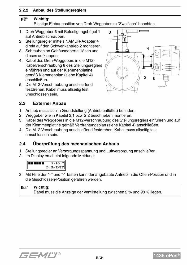
2.2.2 Anbau des Stellungsreglers
Wichtig:Richtige Einbauposition von Dreh-Weggeber zu "Zweiflach" beachten.
1. Dreh-Weggeber 3 mit Befestigungsbügel 1 auf Antrieb schrauben.
2. Stellungsregler mittels NAMUR-Adapter 4 direkt auf den Schwenkantrieb 2 montieren.
3. Schrauben an Gehäuseoberteil lösen und dieses aufklappen.
4. Kabel des Dreh-Weggebers in die M12-Kabelverschraubung 6 des Stellungsreglers einführen und auf der Klemmenplatine gemäß Klemmenplan (siehe Kapitel 4) anschließen.
5. Die M12-Verschraubung anschließend festdrehen. Kabel muss allseitig fest umschlossen sein.
2.3 Externer Anbau
1. Antrieb muss sich in Grundstellung (Antrieb entlüftet) befinden.2. Weggeber wie in Kapitel 2.1 bzw. 2.2 beschrieben montieren.3. Kabel des Weggebers in die M12-Verschraubung des Stellungsreglers einführen und auf
der Klemmenplatine gemäß Verdrahtungsplan (siehe Kapitel 4) anschließen.4. Die M12-Verschraubung anschließend festdrehen. Kabel muss allseitig fest
umschlossen sein.
2.4 Überprüfung des mechanischen Anbaus
1. Stellungsregler an Versorgungsspannung und Luftversorgung anschließen.2. Im Display erscheint folgende Meldung:
3. Mit Hilfe der "+" und "-" Tasten kann der angebaute Antrieb in die Offen-Position und in die Geschlossen-Position gefahren werden.
Wichtig:Dabei muss die Anzeige der Ventilstellung zwischen 2 % und 98 % liegen.
3
1
62
4
1435 ePos®6 / 24
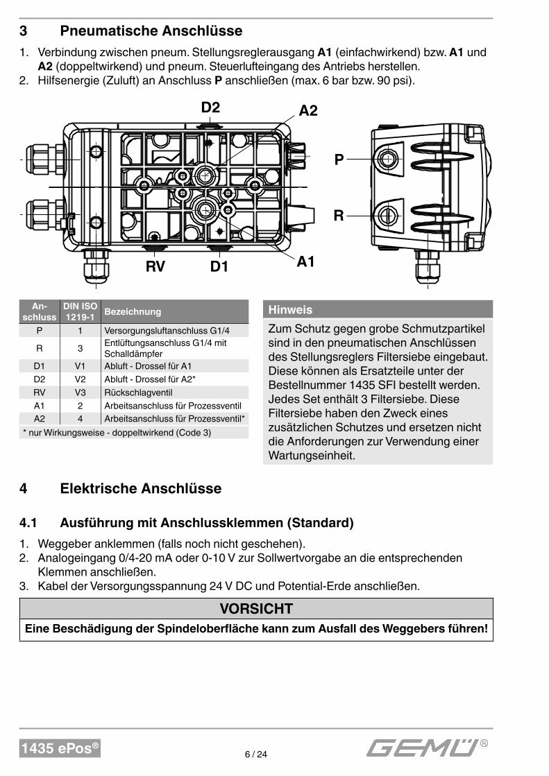
3 Pneumatische Anschlüsse
1. Verbindung zwischen pneum. Stellungsreglerausgang A1 (einfachwirkend) bzw. A1 und A2 (doppeltwirkend) und pneum. Steuerlufteingang des Antriebs herstellen.
2. Hilfsenergie (Zuluft) an Anschluss P anschließen (max. 6 bar bzw. 90 psi).
A2
A1
P
R
D1RV
D2
An-schluss
DIN ISO 1219-1
Bezeichnung
P 1 Versorgungsluftanschluss G1/4
R 3Entlüftungsanschluss G1/4 mit Schalldämpfer
D1 V1 Abluft - Drossel für A1
D2 V2 Abluft - Drossel für A2*
RV V3 Rückschlagventil
A1 2 Arbeitsanschluss für Prozessventil
A2 4 Arbeitsanschluss für Prozessventil*
* nur Wirkungsweise - doppeltwirkend (Code 3)
Hinweis
Zum Schutz gegen grobe Schmutzpartikel sind in den pneumatischen Anschlüssen des Stellungsreglers Filtersiebe eingebaut. Diese können als Ersatzteile unter der Bestellnummer 1435 SFI bestellt werden. Jedes Set enthält 3 Filtersiebe. Diese Filtersiebe haben den Zweck eines zusätzlichen Schutzes und ersetzen nicht die Anforderungen zur Verwendung einer Wartungseinheit.
4 Elektrische Anschlüsse
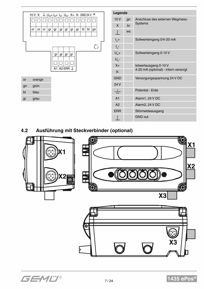
4.1 Ausführung mit Anschlussklemmen (Standard)
1. Weggeber anklemmen (falls noch nicht geschehen).2. Analogeingang 0/4-20 mA oder 0-10 V zur Sollwertvorgabe an die entsprechenden
Klemmen anschließen.3. Kabel der Versorgungsspannung 24 V DC und Potential-Erde anschließen.
VORSICHTEine Beschädigung der Spindeloberfl äche kann zum Ausfall des Weggebers führen!
1435 ePos®7 / 24
10 V X UW+ IW+ IW- UW- X+ X- GND 24 V
or or or gr gr gr gr gr gr bl bl gn
gr gr gr gr
A1 A2 ERR
Legende
10 V gn Anschluss des externen Wegmess-Systems
X br
ws
Iw+ Sollwerteingang 0/4-20 mA
Iw-
Uw+ Sollwerteingang 0-10 V
Uw-
X+ Istwertausgang 0-10 V4-20 mA (optional) - intern versorgt
X-
GND Versorgungsspannung 24 V DC
24 V
Potential - Erde
A1 Alarm1, 24 V DC
A2 Alarm2, 24 V DC
ERR Störmeldeausgang
GND out
or orange
gn grün
bl blau
gr grau
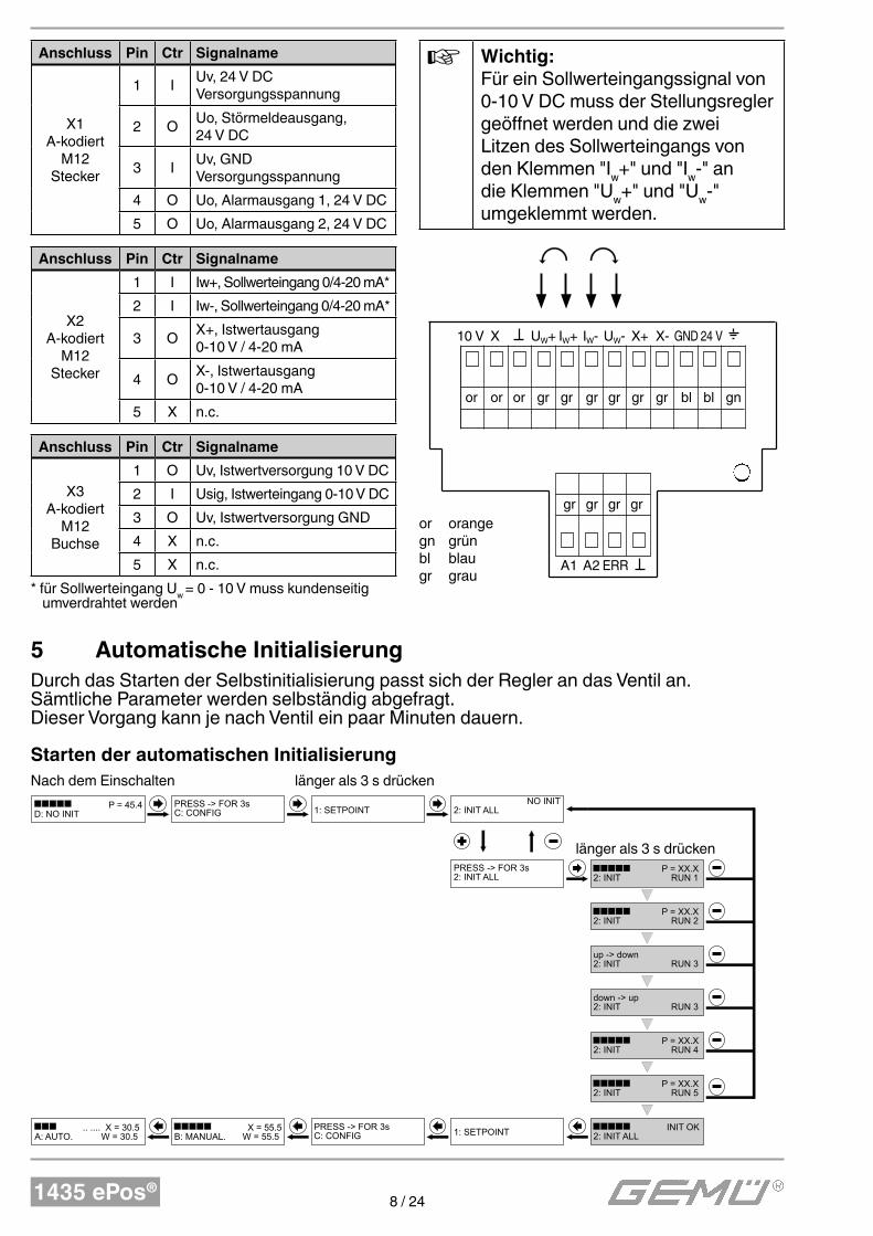
4.2 Ausführung mit Steckverbinder (optional)
X1
X2
X1
X2
X3
X3
4 5
1 2
3
4 5
1 2
3
4 5
1 2
3
1435 ePos®8 / 24
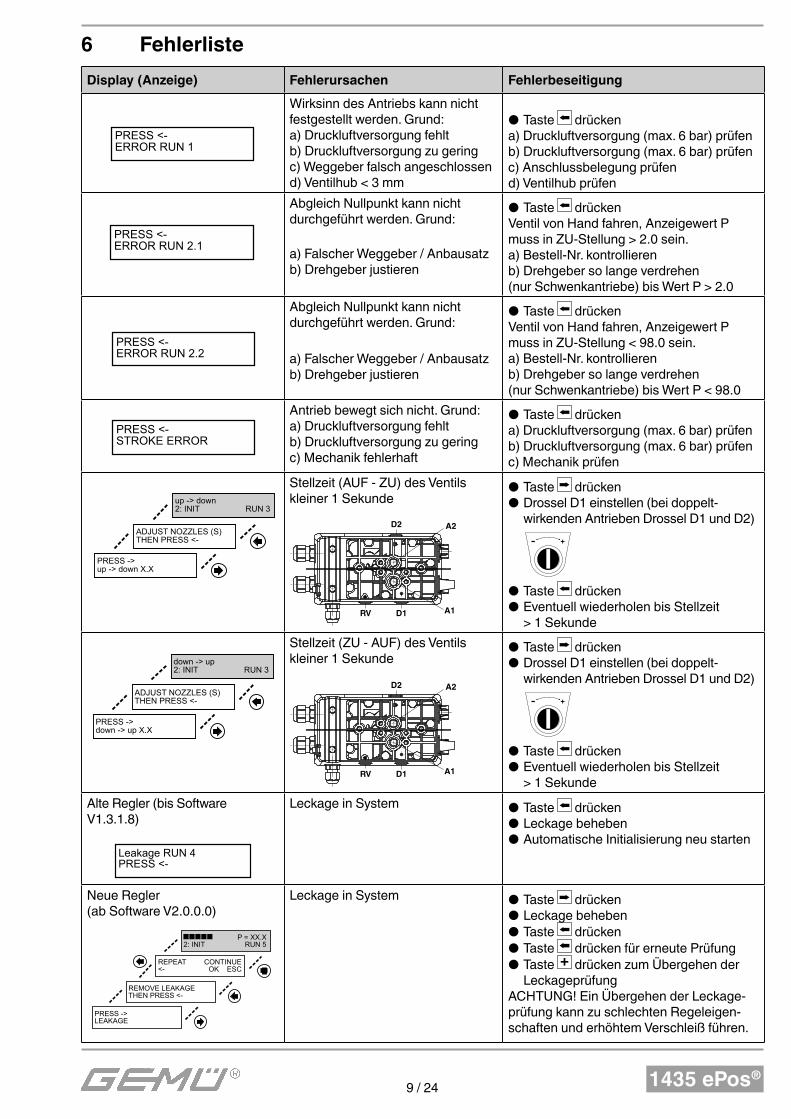
Anschluss Pin Ctr Signalname
X1A-kodiert
M12 Stecker
1 IUv, 24 V DC Versorgungsspannung
2 OUo, Störmeldeausgang, 24 V DC
3 IUv, GND Versorgungsspannung
4 O Uo, Alarmausgang 1, 24 V DC
5 O Uo, Alarmausgang 2, 24 V DC
Anschluss Pin Ctr Signalname
X2A-kodiert
M12 Stecker
1 I Iw+, Sollwerteingang 0/4-20 mA*
2 I Iw-, Sollwerteingang 0/4-20 mA*
3 OX+, Istwertausgang 0-10 V / 4-20 mA
4 OX-, Istwertausgang 0-10 V / 4-20 mA
5 X n.c.
Anschluss Pin Ctr Signalname
X3A-kodiert
M12 Buchse
1 O Uv, Istwertversorgung 10 V DC
2 I Usig, Istwerteingang 0-10 V DC
3 O Uv, Istwertversorgung GND
4 X n.c.
5 X n.c.
* für Sollwerteingang Uw
= 0 - 10 V muss kundenseitig umverdrahtet werden
Wichtig:
Für ein Sollwerteingangssignal von 0-10 V DC muss der Stellungsregler geöffnet werden und die zwei Litzen des Sollwerteingangs von den Klemmen "I
w+" und "I
w-" an
die Klemmen "Uw+" und "U
w-"
umgeklemmt werden.
10 V X UW+ IW+ IW- UW- X+ X- GND 24 V
or or or gr gr gr gr gr gr bl bl gn
gr gr gr gr
A1 A2 ERR
or orangegn grünbl blaugr grau
5 Automatische Initialisierung
Durch das Starten der Selbstinitialisierung passt sich der Regler an das Ventil an. Sämtliche Parameter werden selbständig abgefragt.Dieser Vorgang kann je nach Ventil ein paar Minuten dauern.
Starten der automatischen Initialisierung
P = 45.4D: NO INIT
Nach dem Einschalten
PRESS -> FOR 3s C: CONFIG
1: SETPOINT
NO INIT 2: INIT ALL
PRESS -> FOR 3s 2: INIT ALL
P = XX.X 2: INIT RUN 1
P = XX.X 2: INIT RUN 2
up -> down 2: INIT RUN 3
down -> up 2: INIT RUN 3
P = XX.X 2: INIT RUN 4
P = XX.X 2: INIT RUN 5
INIT OK 2: INIT ALL1: SETPOINT
PRESS -> FOR 3s C: CONFIG
X = 55.5 B: MANUAL. W = 55.5
.. .... X = 30.5 A: AUTO. W = 30.5
länger als 3s drücken
länger als 3 s drücken
länger als 3 s drücken
Nach dem Einschalten
1435 ePos®9 / 24
6 Fehlerliste
Display (Anzeige) Fehlerursachen Fehlerbeseitigung
PRESS <- ERROR RUN 1
Wirksinn des Antriebs kann nicht festgestellt werden. Grund:a) Druckluftversorgung fehltb) Druckluftversorgung zu geringc) Weggeber falsch angeschlossend) Ventilhub < 3 mm
● Taste drückena) Druckluftversorgung (max. 6 bar) prüfenb) Druckluftversorgung (max. 6 bar) prüfenc) Anschlussbelegung prüfend) Ventilhub prüfen
PRESS <- ERROR RUN 2.1
Abgleich Nullpunkt kann nicht durchgeführt werden. Grund:
a) Falscher Weggeber / Anbausatzb) Drehgeber justieren
● Taste drückenVentil von Hand fahren, Anzeigewert P muss in ZU-Stellung > 2.0 sein.a) Bestell-Nr. kontrollierenb) Drehgeber so lange verdrehen (nur Schwenkantriebe) bis Wert P > 2.0
PRESS <- ERROR RUN 2.2
Abgleich Nullpunkt kann nicht durchgeführt werden. Grund:
a) Falscher Weggeber / Anbausatzb) Drehgeber justieren
● Taste drückenVentil von Hand fahren, Anzeigewert P muss in ZU-Stellung < 98.0 sein.a) Bestell-Nr. kontrollierenb) Drehgeber so lange verdrehen (nur Schwenkantriebe) bis Wert P < 98.0
PRESS <-
STROKE ERROR
Antrieb bewegt sich nicht. Grund:a) Druckluftversorgung fehltb) Druckluftversorgung zu geringc) Mechanik fehlerhaft
● Taste drückena) Druckluftversorgung (max. 6 bar) prüfenb) Druckluftversorgung (max. 6 bar) prüfenc) Mechanik prüfen
PRESS -> up -> down X.X
ADJUST NOZZLES (S)THEN PRESS <-
up -> down 2: INIT RUN 3
Stellzeit (AUF - ZU) des Ventils kleiner 1 Sekunde
A2
A1
P
R
D1RV
D2
● Taste drücken ● Drossel D1 einstellen (bei doppelt-wirkenden Antrieben Drossel D1 und D2)
- +
● Taste drücken ● Eventuell wiederholen bis Stellzeit > 1 Sekunde
PRESS -> down -> up X.X
ADJUST NOZZLES (S)THEN PRESS <-
down -> up 2: INIT RUN 3
Stellzeit (ZU - AUF) des Ventils kleiner 1 Sekunde
A2
A1
P
R
D1RV
D2
● Taste drücken ● Drossel D1 einstellen (bei doppelt-wirkenden Antrieben Drossel D1 und D2)
- +
● Taste drücken ● Eventuell wiederholen bis Stellzeit > 1 Sekunde
Alte Regler (bis Software V1.3.1.8)
Leakage RUN 4PRESS <-
Leckage in System ● Taste drücken ● Leckage beheben ● Automatische Initialisierung neu starten
Neue Regler (ab Software V2.0.0.0)
PRESS -> LEAKAGE
REMOVE LEAKAGETHEN PRESS <-
REPEAT CONTINUE <- OK ESC
P = XX.X 2: INIT RUN 5
Leckage in System ● Taste drücken ● Leckage beheben ● Taste drücken ● Taste drücken für erneute Prüfung ● Taste + drücken zum Übergehen der Leckageprüfung
ACHTUNG! Ein Übergehen der Leckage-prüfung kann zu schlechten Regeleigen-schaften und erhöhtem Verschleiß führen.
1435 ePos®10 / 24
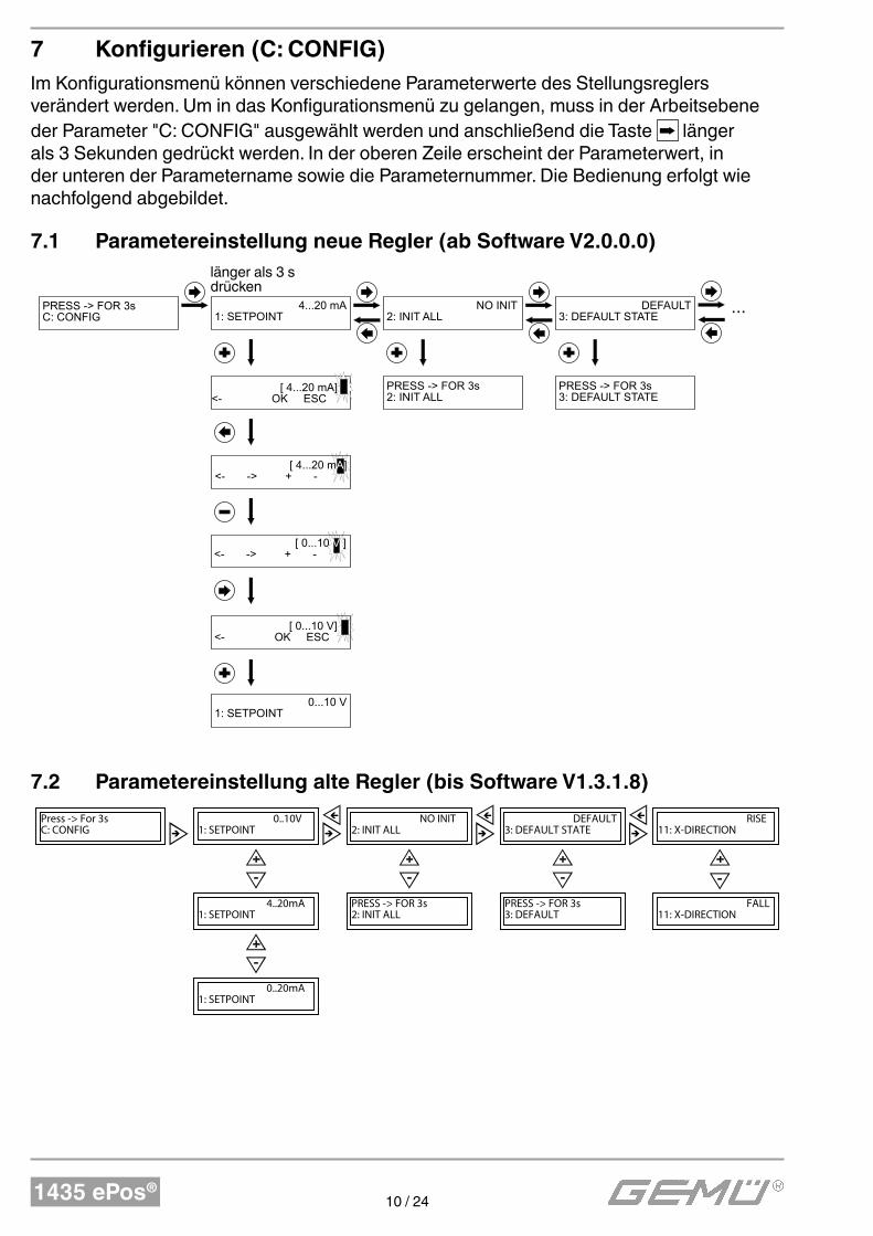
7 Konfigurieren (C: CONFIG)
Im Konfigurationsmenü können verschiedene Parameterwerte des Stellungsreglers verändert werden. Um in das Konfigurations menü zu gelangen, muss in der Arbeitsebene der Parameter "C: CONFIG" ausgewählt werden und anschließend die Taste länger als 3 Sekunden gedrückt werden. In der oberen Zeile erscheint der Parameterwert, in der unteren der Parametername sowie die Parameternummer. Die Bedienung erfolgt wie nachfolgend abgebildet.
7.1 Parametereinstellung neue Regler (ab Software V2.0.0.0)
PRESS -> FOR 3s C: CONFIG
4...20 mA 1: SETPOINT
NO INIT 2: INIT ALL
länger als 3s drücken
[ 4...20 mA] <- OK ESC
[ 4...20 mA] <- -> + -
[ 0...10 V ] <- -> + -
[ 0...10 V] <- OK ESC
0...10 V 1: SETPOINT
DEFAULT 3: DEFAULT STATE
PRESS -> FOR 3s 2: INIT ALL
PRESS -> FOR 3s 3: DEFAULT STATE
...
länger als 3 s drücken
7.2 Parametereinstellung alte Regler (bis Software V1.3.1.8)
0..10V
1: SETPOINT
0..20mA
1: SETPOINT
4..20mA
1: SETPOINT
PRESS -> FOR 3s
2: INIT ALL
NO INIT
2: INIT ALL
PRESS -> FOR 3s
3: DEFAULT
DEFAULT
3: DEFAULT STATE
FALL
11: X-DIRECTION
RISE
11: X-DIRECTION
Press -> For 3s
C: CONFIG
1435 ePos®11 / 24
8 Hinweise
VORSICHT
● Der GEMÜ 1435 ePos® darf ohne Heizelement nicht im Freien eingesetzt werden. Die Version mit Heizelement darf im Freien nur in einem regengeschützten Bereich eingesetzt werden.
● Der GEMÜ 1435 ePos® muss vor direktem Einfl uss von Regenwasser geschützt werden.
Hinweis:
Handhabung, Montage und Inbetriebnahme, sowie Einstell- und Justierarbeiten, dürfen nur von autorisiertem Fachpersonal durchgeführt werden. Für Schäden, welche durch unsachgemäße Handhabung oder Fremdeinwirkung entstehen, übernimmt GEMÜ keinerlei Haftung. Nehmen Sie im Zweifelsfall vor Inbetriebnahme Kontakt mit GEMÜ auf.
Hinweis zur Mitarbeiterschulung:
Zur Mitarbeiterschulung nehmen Sie bitte über die Adresse auf der letzten Seite Kontakt auf.
Im Zweifelsfall oder bei Missverständnissen ist die deutsche Version des Dokuments ausschlaggebend!
1435 ePos®12 / 24
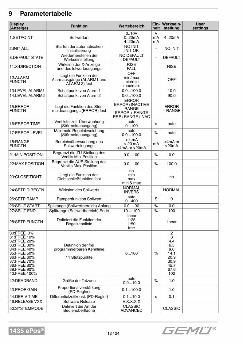
9 Parametertabelle
Display (Anzeige)
Funktion WertebereichEin-heit
Werksein-stellung
User settings
1:SETPOINT Sollwertart0..10V
0..20mA4..20mA
VmAmA
4..20mA
2:INIT ALL Starten der automatischen Initialisierung
NO INITINIT OK - NO INIT
3:DEFAULT STATE Wiederherstellen der Werkseinstellung
NO DEFAULTDEFAULT - DEFAULT
11:X-DIRECTION Wirksinn der X-Anzeige und des Istwertausgangs
RISEFALL RISE
12:ALARM FUNCTN
Legt die Funktion der Alarmausgänge (ALARM1 und
ALARM 2) fest
OFFmin/maxmin/min
max/max
OFF
13:LEVEL ALARM1 Schaltpunkt von Alarm 1 0.0...100.0 10.014:LEVEL ALARM2 Schaltpunkt von Alarm 2 0.0...100.0 90.0
15:ERROR FUNCTN
Legt die Funktion des Stör-meldeausgangs (ERROR) fest
ERRORERROR+INACTIVE
RANGEERROR + RANGE
ERR+RANGE+INAC
ERROR + RANGE
16:ERROR TIME Ventilstellzeit-Überwachung (Störmeldeausgang)
auto0...100 s auto
17:ERROR LEVEL Maximale Regelabweichung (Störmeldeausgang)
auto0.0...100.0 % auto
18:RANGE FUNCTN
Bereichsüberwachung des Sollwerteingangs
< 4 mA> 20 mA
<4mA or >20mAmA <4mA or
>20mA
21:MIN POSITION Begrenzt die ZU-Stellung des Ventils Min. Position 0.0...100 % 0.0
22:MAX POSITION Begrenzt die AUF-Stellung des Ventils Max. Position 0.0...100 % 100.0
23:CLOSE TIGHT Legt die Funktion der Dichtschließfunktion fest
nominmax
min & max
no
24:SETP DIRECTN Wirksinn des Sollwerts NORMALINVERS NORMAL
25:SETP RAMP Rampenfunktion Sollwert auto0...400 S 0
26:SPLIT START Splitrange (Sollwertbereich) Anfang 0.0 ... 90 % 0.027:SPLIT END Splitrange (Sollwertbereich) Ende 10 ... 100 % 100
28:SETP FUNCTN Definiert die Funktion der Regelkennlinie
linear1:251:50free
linear
30:FREE 0%31:FREE 10%32:FREE 20%33:FREE 30%34:FREE 40%35:FREE 50%36:FREE 60%37:FREE 70%38:FREE 80%39:FREE 90%40:FREE 100%
Definition der frei programmierbaren Kennlinie
11 Stützpunkte0...100 %
23
4.46.59.6
14.120.930.945.767.6100
42:DEADBAND Größe der Totzone auto0.0...10.0 % 1.0
43:PROP GAIN Proportionalverstärkung (PD-Regler) 0.1...100.0 1.0
44:DERIV TIME Differentialzeitkonst. (PD-Regler) 0.1...10.0 s 0.146:RELEASE VXX Software Release V X.X.X.X
50:SYSTEMMODE Definiert die Art der Bedienoberfläche
CLASSICADVANCED CLASSIC
1435 ePos®13 / 24
Contents
1 Safety instructions 13
2 Mechanical mounting 13
2.1 Mounting to linear actuators 132.1.1 Preparation of the valve actuator 132.1.2 Completing the travel sensor 132.1.3 Mounting the positioner 142.2 Mounting to quarter turn actuators 152.2.1 Preparation of the valve actuator 152.2.2 Mounting the positioner 162.3 Remote mounting 162.4 Checking the mounted assembly 163 Pneumatic connections 17
4 Electrical connections 17
4.1 Version with terminals (standard) 174.2 Version with connector (optional) 185 Automatic initialisation 19
6 Error list 20
7 Configuring (C: CONFIG) 21
7.1 Parameter setting for new positioners (from software V2.0.0.0) 217.2 Parameter setting for old positioners (up to software V1.3.1.8) 218 Information 22
9 Parameter table 23
1 Safety instructions
Please refer to the safety instructions included in the GEMÜ 1435 ePos® operating instructions on the enclosed CD ROM. If you do not have this CD ROM, please contact GEMÜ.
2 Mechanical mounting
2.1 Mounting to linear actuators
2.1.1 Preparation of the valve actuator
l The actuator must be in the zero position (actuator vented).
l If there is an optical position indicator in the actuator (a red spindle), it must be pulled out.
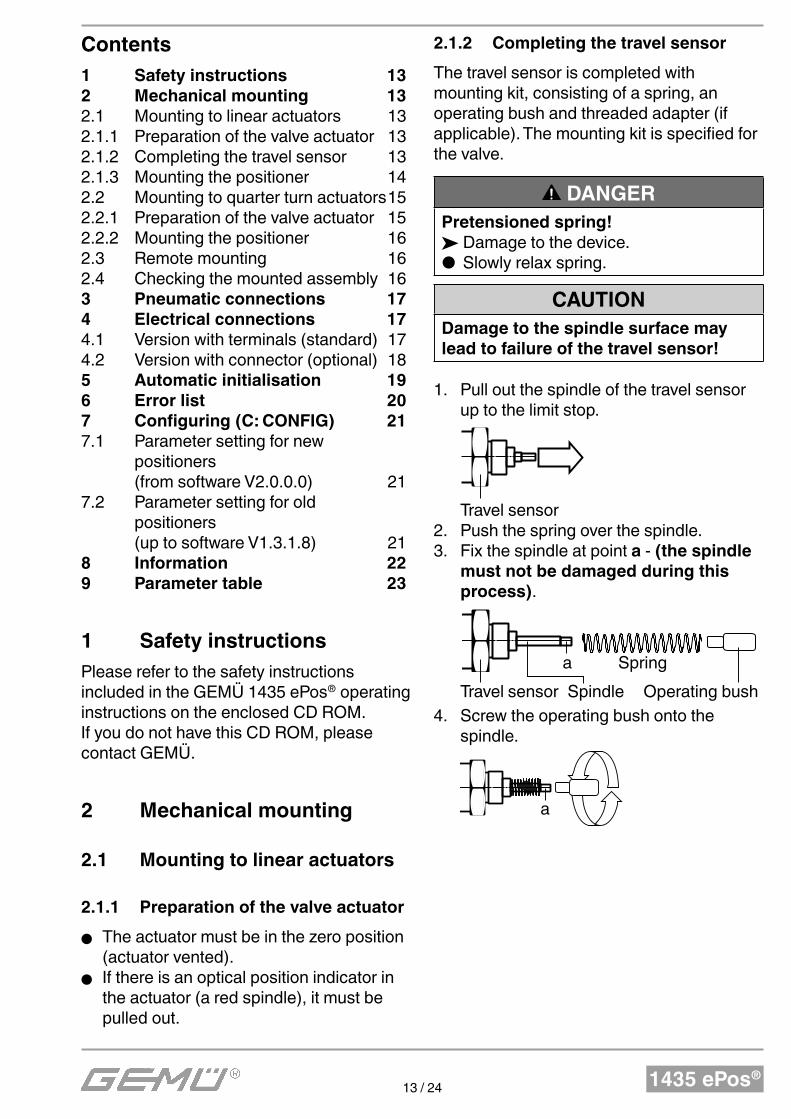
2.1.2 Completing the travel sensor
The travel sensor is completed with mounting kit, consisting of a spring, an operating bush and threaded adapter (if applicable). The mounting kit is specified for the valve.
DANGER
Pretensioned spring! ä Damage to the device. ● Slowly relax spring.
CAUTIONDamage to the spindle surface may lead to failure of the travel sensor!
1. Pull out the spindle of the travel sensor up to the limit stop.
Travel sensor2. Push the spring over the spindle. 3. Fix the spindle at point a - (the spindle
must not be damaged during this process).
Travel sensor Spindle
a Spring
Operating bush
4. Screw the operating bush onto the spindle.
a
1435 ePos®14 / 24
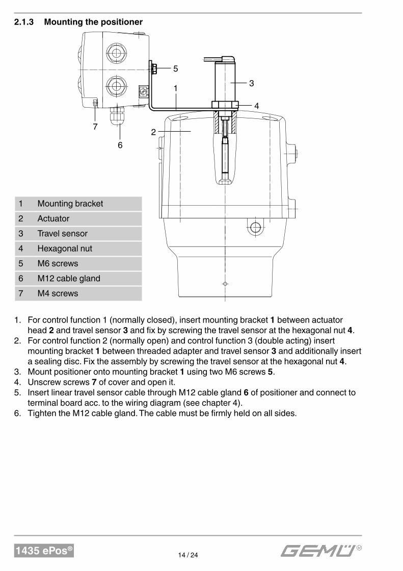
2.1.3 Mounting the positioner
5
7
6
2
13
4
1 Mounting bracket
2 Actuator
3 Travel sensor
4 Hexagonal nut
5 M6 screws
6 M12 cable gland
7 M4 screws
1. For control function 1 (normally closed), insert mounting bracket 1 between actuator head 2 and travel sensor 3 and fix by screwing the travel sensor at the hexagonal nut 4.
2. For control function 2 (normally open) and control function 3 (double acting) insert mounting bracket 1 between threaded adapter and travel sensor 3 and additionally insert a sealing disc. Fix the assembly by screwing the travel sensor at the hexagonal nut 4.
3. Mount positioner onto mounting bracket 1 using two M6 screws 5.4. Unscrew screws 7 of cover and open it.5. Insert linear travel sensor cable through M12 cable gland 6 of positioner and connect to
terminal board acc. to the wiring diagram (see chapter 4).6. Tighten the M12 cable gland. The cable must be firmly held on all sides.
1435 ePos®15 / 24
2.2 Mounting to quarter turn actuators
2.2.1 Preparation of the valve actuator
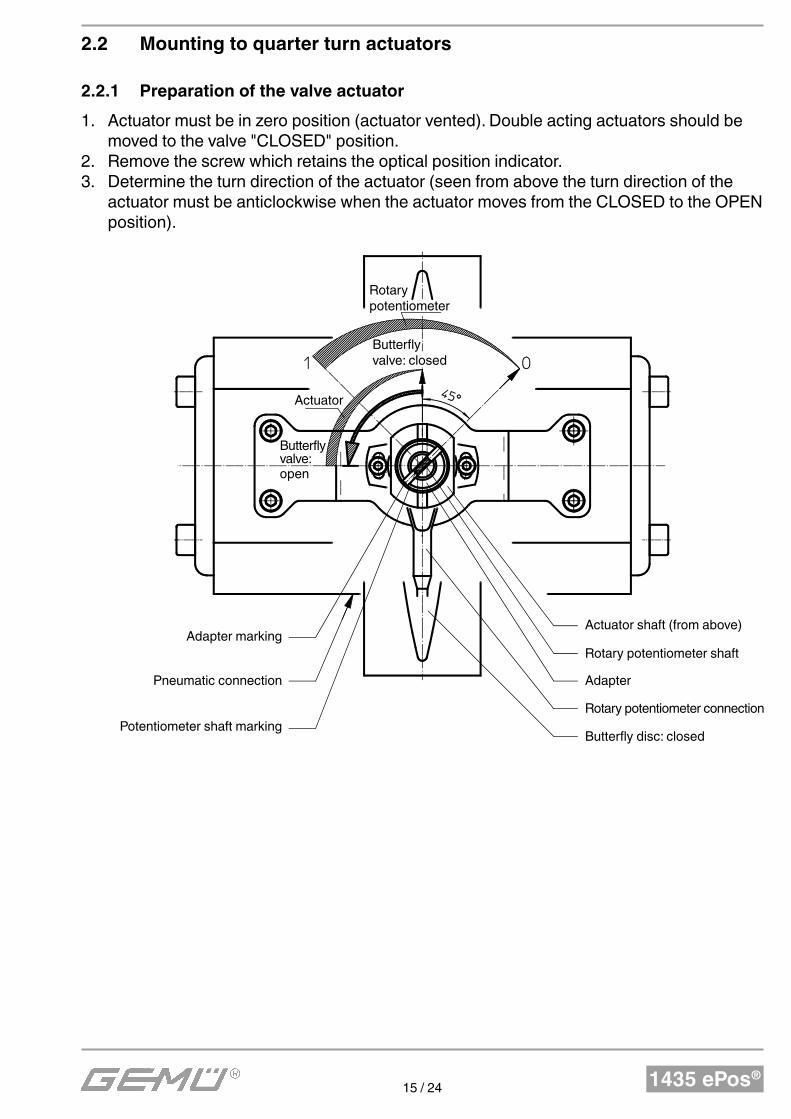
1. Actuator must be in zero position (actuator vented). Double acting actuators should be moved to the valve "CLOSED" position.
2. Remove the screw which retains the optical position indicator.3. Determine the turn direction of the actuator (seen from above the turn direction of the
actuator must be anticlockwise when the actuator moves from the CLOSED to the OPEN position).
Actuator shaft (from above)
Rotary potentiometer shaft
Adapter
Rotary potentiometer connection
Butterfly disc: closed
Adapter marking
Pneumatic connection
Potentiometer shaft marking
Rotarypotentiometer
Actuator
Butterfly valve: open
Butterfly valve: closed
1435 ePos®16 / 24
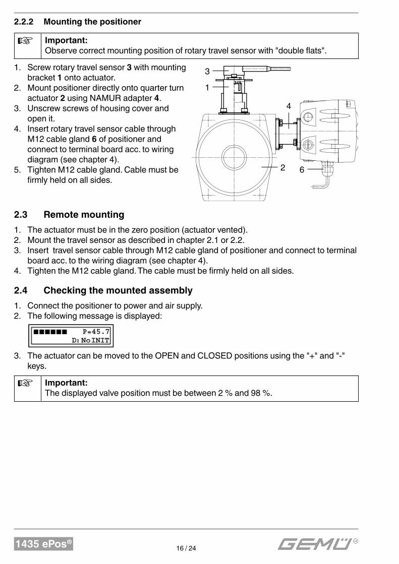
2.2.2 Mounting the positioner
Important:
Observe correct mounting position of rotary travel sensor with "double flats".
1. Screw rotary travel sensor 3 with mounting bracket 1 onto actuator.
2. Mount positioner directly onto quarter turn actuator 2 using NAMUR adapter 4.
3. Unscrew screws of housing cover and open it.
4. Insert rotary travel sensor cable through M12 cable gland 6 of positioner and connect to terminal board acc. to wiring diagram (see chapter 4).
5. Tighten M12 cable gland. Cable must be firmly held on all sides.
2.3 Remote mounting
1. The actuator must be in the zero position (actuator vented).2. Mount the travel sensor as described in chapter 2.1 or 2.2.3. Insert travel sensor cable through M12 cable gland of positioner and connect to terminal
board acc. to the wiring diagram (see chapter 4).4. Tighten the M12 cable gland. The cable must be firmly held on all sides.
2.4 Checking the mounted assembly
1. Connect the positioner to power and air supply.2. The following message is displayed:
3. The actuator can be moved to the OPEN and CLOSED positions using the "+" and "-" keys.
Important:
The displayed valve position must be between 2 % and 98 %.
3
1
62
4
1435 ePos®17 / 24
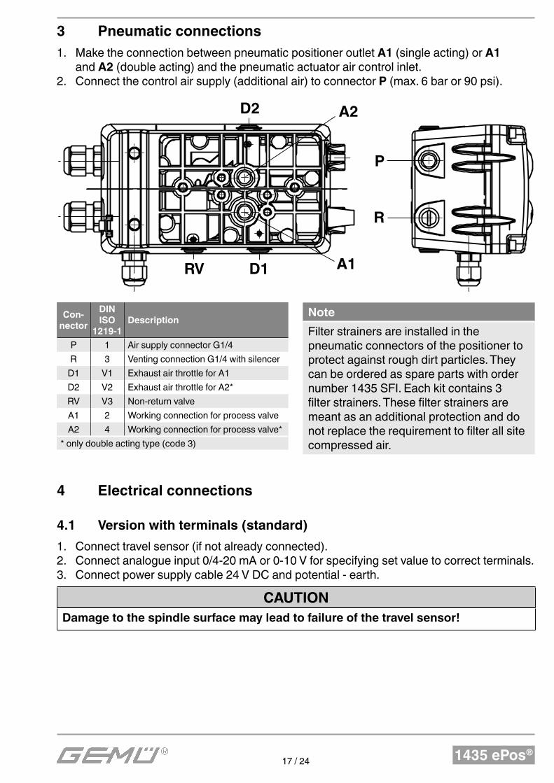
3 Pneumatic connections
1. Make the connection between pneumatic positioner outlet A1 (single acting) or A1 and A2 (double acting) and the pneumatic actuator air control inlet.
2. Connect the control air supply (additional air) to connector P (max. 6 bar or 90 psi).
A2
A1
P
R
D1RV
D2
Con-
nector
DIN
ISO
1219-1
Description
P 1 Air supply connector G1/4
R 3 Venting connection G1/4 with silencer
D1 V1 Exhaust air throttle for A1
D2 V2 Exhaust air throttle for A2*
RV V3 Non-return valve
A1 2 Working connection for process valve
A2 4 Working connection for process valve*
* only double acting type (code 3)
Note
Filter strainers are installed in the pneumatic connectors of the positioner to protect against rough dirt particles. They can be ordered as spare parts with order number 1435 SFI. Each kit contains 3 filter strainers. These filter strainers are meant as an additional protection and do not replace the requirement to filter all site compressed air.
4 Electrical connections
4.1 Version with terminals (standard)
1. Connect travel sensor (if not already connected).2. Connect analogue input 0/4-20 mA or 0-10 V for specifying set value to correct terminals.3. Connect power supply cable 24 V DC and potential - earth.
CAUTION
Damage to the spindle surface may lead to failure of the travel sensor!
1435 ePos®18 / 24
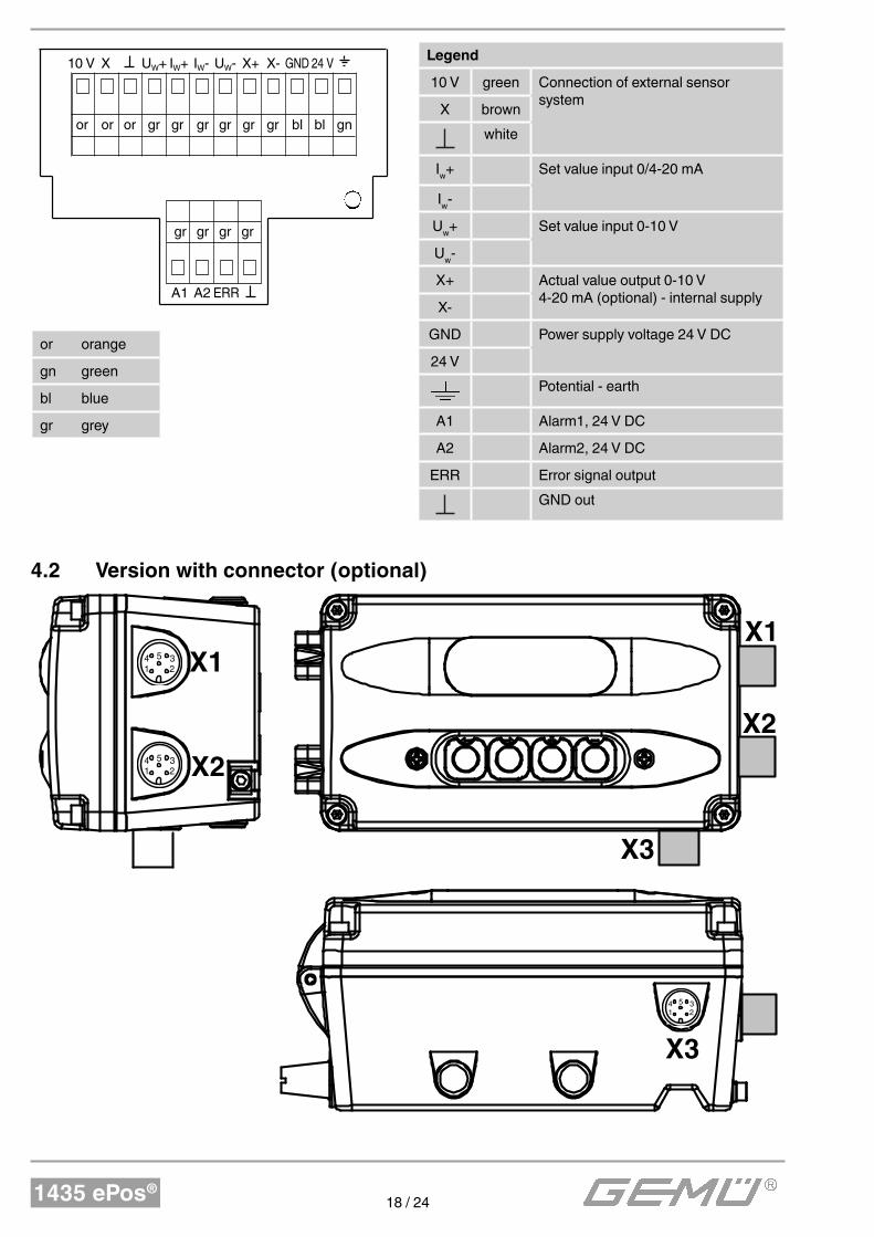
Legend
10 V green Connection of external sensor system
X brown
white
Iw+ Set value input 0/4-20 mA
Iw-
Uw+ Set value input 0-10 V
Uw-
X+ Actual value output 0-10 V4-20 mA (optional) - internal supply
X-
GND Power supply voltage 24 V DC
24 V
Potential - earth
A1 Alarm1, 24 V DC
A2 Alarm2, 24 V DC
ERR Error signal output
GND out
10 V X UW+ IW+ IW- UW- X+ X- GND 24 V
or or or gr gr gr gr gr gr bl bl gn
gr gr gr gr
A1 A2 ERR
or orange
gn green
bl blue
gr grey
4.2 Version with connector (optional)
X1
X2
X1
X2
X3
X3
4 5
1 2
3
4 5
1 2
3
4 5
1 2
3
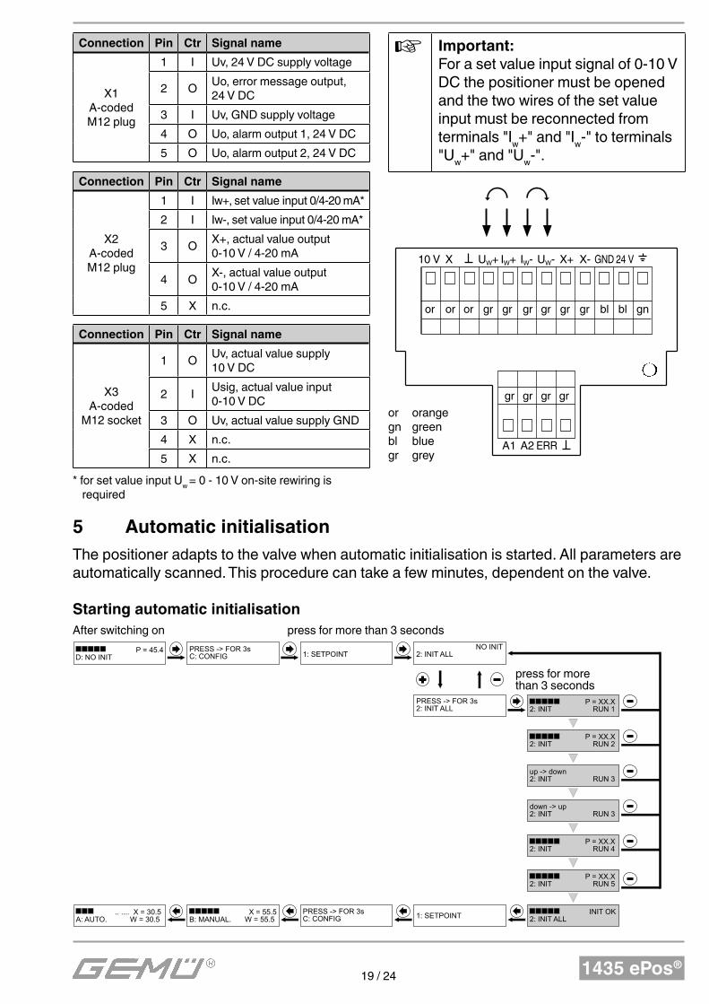
1435 ePos®19 / 24
Connection Pin Ctr Signal name
X1A-codedM12 plug
1 I Uv, 24 V DC supply voltage
2 OUo, error message output, 24 V DC
3 I Uv, GND supply voltage
4 O Uo, alarm output 1, 24 V DC
5 O Uo, alarm output 2, 24 V DC
Connection Pin Ctr Signal name
X2A-codedM12 plug
1 I Iw+, set value input 0/4-20 mA*
2 I Iw-, set value input 0/4-20 mA*
3 OX+, actual value output 0-10 V / 4-20 mA
4 OX-, actual value output 0-10 V / 4-20 mA
5 X n.c.
Connection Pin Ctr Signal name
X3A-coded
M12 socket
1 OUv, actual value supply 10 V DC
2 IUsig, actual value input 0-10 V DC
3 O Uv, actual value supply GND
4 X n.c.
5 X n.c.
* for set value input Uw
= 0 - 10 V on-site rewiring is required
Important:
For a set value input signal of 0-10 V DC the positioner must be opened and the two wires of the set value input must be reconnected from terminals "I
w+" and "I
w-" to terminals
"Uw+" and "U
w-".
or orangegn greenbl bluegr grey
10 V X UW+ IW+ IW- UW- X+ X- GND 24 V
or or or gr gr gr gr gr gr bl bl gn
gr gr gr gr
A1 A2 ERR
5 Automatic initialisation
The positioner adapts to the valve when automatic initialisation is started. All parameters are automatically scanned. This procedure can take a few minutes, dependent on the valve.
Starting automatic initialisation
P = 45.4D: NO INIT
Nach dem Einschalten
PRESS -> FOR 3s C: CONFIG
1: SETPOINT
NO INIT 2: INIT ALL
PRESS -> FOR 3s 2: INIT ALL
P = XX.X 2: INIT RUN 1
P = XX.X 2: INIT RUN 2
up -> down 2: INIT RUN 3
down -> up 2: INIT RUN 3
P = XX.X 2: INIT RUN 4
P = XX.X 2: INIT RUN 5
INIT OK 2: INIT ALL1: SETPOINT
PRESS -> FOR 3s C: CONFIG
X = 55.5 B: MANUAL. W = 55.5
.. .... X = 30.5 A: AUTO. W = 30.5
länger als 3s drücken
press for more than 3 seconds
press for more than 3 seconds
After switching on
1435 ePos®20 / 24
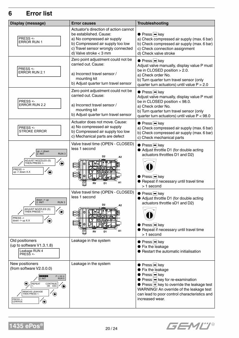
6 Error list
Display (message) Error causes Troubleshooting
PRESS <- ERROR RUN 1
Actuator's direction of action cannot be established. Cause:a) No compressed air supplyb) Compressed air supply too lowc) Travel sensor wrongly connectedd) Valve stroke < 3 mm
● Press keya) Check compressed air supply (max. 6 bar)b) Check compressed air supply (max. 6 bar)c) Check connection assignmentd) Check valve stroke
PRESS <- ERROR RUN 2.1
Zero point adjustment could not be carried out. Cause:
a) Incorrect travel sensor / mounting kit
b) Adjust quarter turn travel sensor
● Press keyAdjust valve manually, display value P must be in CLOSED position > 2.0.a) Check order No.b) Turn quarter turn travel sensor (only quarter turn actuators) until value P > 2.0
PRESS <- ERROR RUN 2.2
Zero point adjustment could not be carried out. Cause:
a) Incorrect travel sensor / mounting kit
b) Adjust quarter turn travel sensor
● Press keyAdjust valve manually, display value P must be in CLOSED position < 98.0.a) Check order No.b) Turn quarter turn travel sensor (only quarter turn actuators) until value P < 98.0
PRESS <-
STROKE ERROR
Actuator does not move. Cause:a) No compressed air supplyb) Compressed air supply too lowc) Mechanical parts are defect
● Press keya) Check compressed air supply (max. 6 bar)b) Check compressed air supply (max. 6 bar)c) Check mechanical parts
PRESS -> up -> down X.X
ADJUST NOZZLES (S)THEN PRESS <-
up -> down 2: INIT RUN 3
Valve travel time (OPEN - CLOSED) less 1 second
A2
A1
P
R
D1RV
D2
● Press key ● Adjust throttle D1 (for double acting actuators throttles D1 and D2)
- +
● Press key ● Repeat if necessary until travel time > 1 second
PRESS -> down -> up X.X
ADJUST NOZZLES (S)THEN PRESS <-
down -> up 2: INIT RUN 3
Valve travel time (OPEN - CLOSED) less 1 second
A2
A1
P
R
D1RV
D2
● Press key ● Adjust throttle D1 (for double acting actuators throttle sD1 and D2)
- +
● Press key ● Repeat if necessary until travel time > 1 second
Old positioners (up to software V1.3.1.8)
Leakage RUN 4PRESS <-
Leakage in the system ● Press key ● Fix the leakage ● Restart the automatic initialisation
New positioners (from software V2.0.0.0)
PRESS -> LEAKAGE
REMOVE LEAKAGETHEN PRESS <-
REPEAT CONTINUE <- OK ESC
P = XX.X 2: INIT RUN 5
Leakage in the system ● Press key ● Fix the leakage ● Press key ● Press key for re-examination ● Press + key to override the leakage test
WARNING! An override of the leakage test can lead to poor control characteristics and increased wear.
1435 ePos®21 / 24
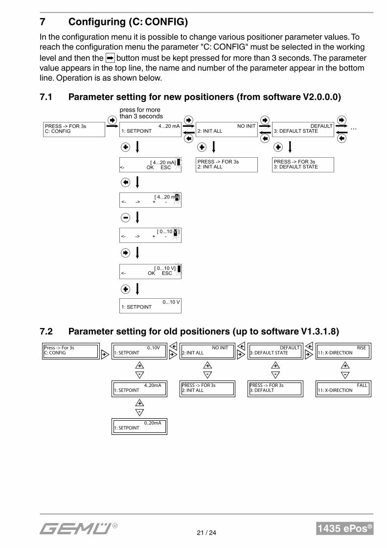
7 Configuring (C: CONFIG)
In the configuration menu it is possible to change various positioner parameter values. To reach the configuration menu the parameter "C: CONFIG" must be selected in the working level and then the button must be kept pressed for more than 3 seconds. The parameter value appears in the top line, the name and number of the parameter appear in the bottom line. Operation is as shown below.
7.1 Parameter setting for new positioners (from software V2.0.0.0)
PRESS -> FOR 3s C: CONFIG
4...20 mA 1: SETPOINT
NO INIT 2: INIT ALL
länger als 3s drücken
[ 4...20 mA] <- OK ESC
[ 4...20 mA] <- -> + -
[ 0...10 V ] <- -> + -
[ 0...10 V] <- OK ESC
0...10 V 1: SETPOINT
DEFAULT 3: DEFAULT STATE
PRESS -> FOR 3s 2: INIT ALL
PRESS -> FOR 3s 3: DEFAULT STATE
...
press for more than 3 seconds
7.2 Parameter setting for old positioners (up to software V1.3.1.8)
0..10V
1: SETPOINT
0..20mA
1: SETPOINT
4..20mA
1: SETPOINT
PRESS -> FOR 3s
2: INIT ALL
NO INIT
2: INIT ALL
PRESS -> FOR 3s
3: DEFAULT
DEFAULT
3: DEFAULT STATE
FALL
11: X-DIRECTION
RISE
11: X-DIRECTION
Press -> For 3s
C: CONFIG
1435 ePos®22 / 24
8 Information
CAUTION
● The GEMÜ 1435 ePos® must not be used outdoors without heating element. The version with heating element may only be used outdoors in a rain-protected area.
● The GEMÜ 1435 ePos® must be protected from direct impact of rain water.
Note:
Handling, assembly, commissioning, setting and adjustment may only be carried out by authorised specialist staff . GEMÜ shall assume no liability whatsoever for damages caused by improper handling or third-party actions.In case of doubt, contact GEMÜ before commissioning.
Note on staff training:
Please contact us at the address on the last page for staff training information.
Should there be any doubts or misunderstandings in the preceding text, the German version of this document is the authoritative document!
1435 ePos®23 / 24
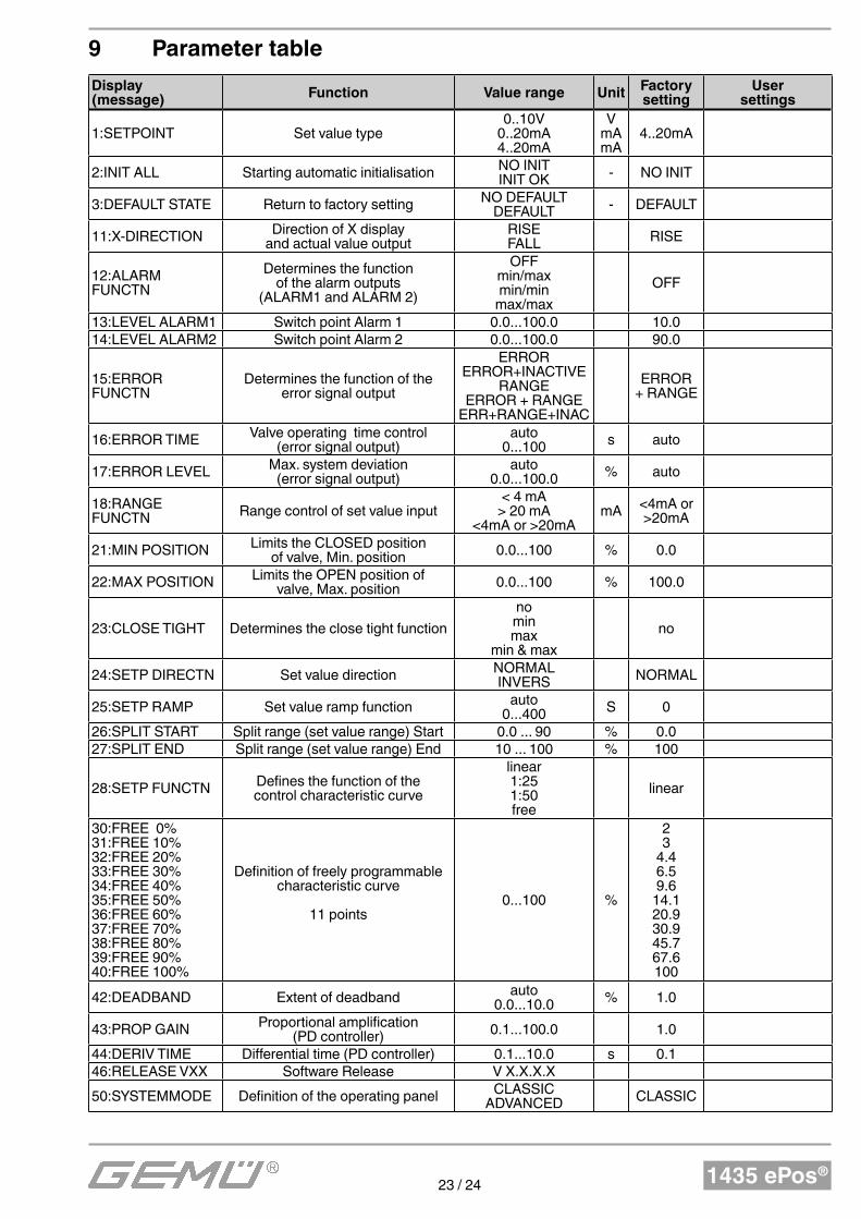
9 Parameter table
Display (message)
Function Value range UnitFactorysetting
User settings
1:SETPOINT Set value type0..10V
0..20mA4..20mA
VmAmA
4..20mA
2:INIT ALL Starting automatic initialisation NO INITINIT OK - NO INIT
3:DEFAULT STATE Return to factory setting NO DEFAULTDEFAULT - DEFAULT
11:X-DIRECTION Direction of X display and actual value output
RISEFALL RISE
12:ALARM FUNCTN
Determines the function of the alarm outputs
(ALARM1 and ALARM 2)
OFFmin/maxmin/min
max/max
OFF
13:LEVEL ALARM1 Switch point Alarm 1 0.0...100.0 10.014:LEVEL ALARM2 Switch point Alarm 2 0.0...100.0 90.0
15:ERROR FUNCTN
Determines the function of the error signal output
ERRORERROR+INACTIVE
RANGEERROR + RANGE
ERR+RANGE+INAC
ERROR + RANGE
16:ERROR TIME Valve operating time control (error signal output)
auto0...100 s auto
17:ERROR LEVEL Max. system deviation(error signal output)
auto0.0...100.0 % auto
18:RANGE FUNCTN Range control of set value input
< 4 mA> 20 mA
<4mA or >20mAmA <4mA or
>20mA
21:MIN POSITION Limits the CLOSED position of valve, Min. position 0.0...100 % 0.0
22:MAX POSITION Limits the OPEN position of valve, Max. position 0.0...100 % 100.0
23:CLOSE TIGHT Determines the close tight function
nominmax
min & max
no
24:SETP DIRECTN Set value direction NORMALINVERS NORMAL
25:SETP RAMP Set value ramp function auto0...400 S 0
26:SPLIT START Split range (set value range) Start 0.0 ... 90 % 0.027:SPLIT END Split range (set value range) End 10 ... 100 % 100
28:SETP FUNCTN Defines the function of the control characteristic curve
linear1:251:50free
linear
30:FREE 0%31:FREE 10%32:FREE 20%33:FREE 30%34:FREE 40%35:FREE 50%36:FREE 60%37:FREE 70%38:FREE 80%39:FREE 90%40:FREE 100%
Definition of freely programmable characteristic curve
11 points0...100 %
23
4.46.59.6
14.120.930.945.767.6100
42:DEADBAND Extent of deadband auto0.0...10.0 % 1.0
43:PROP GAIN Proportional amplification (PD controller) 0.1...100.0 1.0
44:DERIV TIME Differential time (PD controller) 0.1...10.0 s 0.146:RELEASE VXX Software Release V X.X.X.X
50:SYSTEMMODE Definition of the operating panel CLASSICADVANCED CLASSIC

Änd
erun
gen
vorb
ehal
ten
· Sub
ject
to a
ltera
tion
· 03/
2015
· 88
2776
29
VENTIL-, MESS- UND REGELSYSTEME
VALVES, MEASUREMENT AND CONTROL SYSTEMS
GEMÜ Gebr. Müller Apparatebau GmbH & Co. KG · Fritz-Müller-Str. 6-8 · D-74653 Ingelfi ngen-CriesbachTelefon +49(0)7940/123-0 · Telefax +49(0)7940/123-192 · [email protected] · www.gemu-group.com