QR-6550 E PDF - Time Clocks Australia · TABLE OF CONTENTS PRECAUTIONS FEATURES Environmental...
68
QUARTZ TIME RECORDER USER’S MANUAL
Transcript of QR-6550 E PDF - Time Clocks Australia · TABLE OF CONTENTS PRECAUTIONS FEATURES Environmental...

QUARTZ TIME RECORDER
USER’S MANUAL


INTRODUCTIONThank you for purchasing our Quartz Time Recorder. For safe and proper operation, please carefully read this manual before using it and save it for reference.
Die in dieser Bedienungsanleitung enthaltenen Angaben können jederzeit ohne vorherige Ankündigung geändert werden.
Diese Bedienungsanleitung wurde mit äußerster Sorgfalt erstellt, um alle Einzelheiten hinsichtlich der Bedienung des Zeiterfassungsgerätes darzustellen. Sollten Sie dennoch Fragen haben oder Fehler in der Anleitung entdecken, nehmen Sie bitte mit uns Kontakt auf.
Wir haften nicht für direkte oder indirekte Schäden, die durch die Verwendung dieser Betriebsanleitung entstehen.
Lesen Sie diese Anleitung aufmerksam und benutzen Sie lhr Zeiterfassungsgerät erst dann, wenn Sie die Angaben über die Hardware und Software richtig verstanden haben.
The details of this User's Manual are subject to change without previous notification.This User's Manual has been prepared with the utmost care to cover all aspects of the time recorder's use.If you feel, however, that some explanations are inadequate, unclear, or difficult to understand, please do not hesitate to contact the dealer or the shop from which you have purchased your Time Recorder.Be sure to use your Time Recorder after you have fully understood the hardware and software specifications and limits.No part of this publication may be reproduced, stored in a retrieval system, or transmitted, in any form or by any means, mechanical, photocopying, recording or otherwise. Place the time recorder at the position close to the wall outlet so that it is easily
accessible to disconnect.
Bescheinigung des Herstellers/Importeurs
Dies Gerät entspricht den Bedingungen der Niederspannungs-Vorschrift
73/23/EEC und dem EMVG nach 89/336/EEC.
This unit complies with the Low Voltage Directive 73/23/EEC and the
EMC Directive 89/336/EEC.
Maschinenlärminformations-Verordnung 3. GPSGV:
Der höchste Schalldruckpegel beträgt 70 dB (A) oder weniger gemäss
EN ISO 7779.
Die zugehorige Steckdose muß nahe beim Gerät angebracht und leicht
zugänglich sein.
1.2.
3.
4.
1

TABLE OF CONTENTS
PRECAUTIONSFEATURESEnvironmental Conditions
GETTING STARTEDUnpacking the QR-6550 / 6560OverviewInstalling Ribbon Cassette
OVERVIEW OF OPERATIONSETTINGSPreparation for SettingsOverview of Control ButtonsSelecting the Hour Display FormatSetting the TimeSetting the DateSelecting the Card Type Setting Pay Period Ending Date/Day Monthly / Weekly / Bi-weeklySetting the Day Advance TimeSelecting the Print FormatSelecting the LanguageSetting the Daylight Saving Time Deleting the Daylight Saving Time SettingsSetting the Weekly Program Confirming the Weekly Program Changing the Weekly Program Deleting the Weekly ProgramSetting Duration of External Time Signal (QR-6560)Selecting Volume of Melodies (QR-6560) Setting the Password How to Change Settings When the Password Is Set Canceling the Password
PRINTING LIST OF SETTING INFORMATIONRESETTINGCard Resetting (QR-6560)
MOUNTING UNIT ON WALLINSTALLING THE OPTIONAL BATTERY BACK-UPCONNECTING EXTERNAL TIME SIGNALTROUBLESHOOTINGSPECIFICATIONSTIME CARD SPECIFICATIONS
Template for wall mounting
1.2.
3.
4.5.
6.7.
8.9.
10.11.12.13.
155
6667
91111121314151618182122232427283838383940414243
444647
484950525456
61

1. PRECAUTIONSThis operation manual is prepared for safe and proper use of the unit. Please follow all the instructions to avoid possible danger to yourself or others and damage to the unit.
Signs
Various warnings and cautions are provided throughout this manual along with signs.
Remember each sign and its explanation listed below for your safety and proper
operation of the unit.
Caution
Warning
Improper handling may cause electric shock DANGER.
DO NOT disassemble the unit.
"Don't" sign.
"Must-Do" sign.
Be sure to remove the line cord plug from the outlet.
Do not disassemble the unit. There is a high voltage present inside, possibly leading to an electric shock.
Do not use any voltage of the power source other than designated. Do not share a single outlet with another plug. These may lead to fire or shock hazards.
Do not damage, break, or modify the power cord. Do not put a heavy object on, pull, or forcefully bend the cord, either. These may damage the cord, possibly resulting in a fire or electric shock.
If any anomaly occurs, for example, heat or smoke is generated or an odor is emitted, unplug the unit immediately and contact your dealer for servicing. There is a danger that further use may cause a fire or electric shock.
Do not modify the unit. Modifications may cause a fire and/or electric shock.
Warning
Improper handling may cause bodily accidents includingdeath and serious injury.
Improper handling may harm the human body or material.
1 1
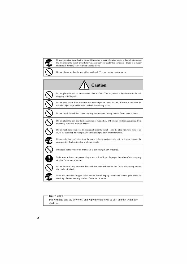
If foreign matter should get in the unit (including a piece of metal, water, or liquid), disconnect the plug from the outlet immediately and contact your dealer for servicing. There is a danger that further use may cause a fire or electric shock.
Do not place the unit on an uneven or tilted surface. This may result in injuries due to the unit dropping or falling off.
Do not put a water-filled container or a metal object on top of the unit. If water is spilled or the metallic object slips inside, a fire or shock hazard may occur.
Do not place the unit near kitchen counter or humidifier. Oil, smoke, or steam generating from them may cause fire or shock hazards.
Do not yank the power cord to disconnect from the outlet. Hold the plug with your hand to do so, or the cord may be damaged, possibly leading to a fire or electric shock.
Remove the line cord plug from the outlet before transferring the unit, or it may damage the cord, possibly leading to a fire or electric shock.
Make sure to insert the power plug as far as it will go. Improper insertion of the plug may develop fire or shock hazards.
Do not insert or drop any other time card than specified into the slot. Such misuse may cause a fire or electric shock.
If the unit should be dropped or the case be broken, unplug the unit and contact your dealer for servicing. Further use may lead to a fire or shock hazard.
Be careful not to contact the print head, as you may get hurt or burned.
Do not install the unit in a humid or dusty environment. It may cause a fire or electric shock.
Do not plug or unplug the unit with a wet hand. You may get an electric shock.
Daily CareFor cleaning, turn the power off and wipe the case clean of dust and dirt with a dry
cloth, etc.
Caution
2 2

VorsichtsmassnahmenDieses Bedienerhandbuch stellt die sichere und ordnungsgemäße Verwendung des Geräts sicher. Befolgen der Anweisungen schützt den Bediener und andere vor Verletzungen und verhindert die Beschädigung des Geräts.
Warnschilder Nachfolgend werden Schilder mit Warn- und Vorsichtshinweisen dargestellt. Um das Gerät sicher und ordnungsgemäß handhaben zu können, hat sich der Bediener jedes Schild und die nachstehende Erklärung zu beachten.
Vorsicht
Achtung
Unangebrachte Handhabung kann zu GEFAHREN wie elektrischen Schlag führen.
Das Gerät NICHT auseinandernehmen.
Das Schild weist auf zu unterlassende Handlungen hin.
Das Schild weist auf unbedingt erforderliche Handlungen hin.
Den Stecker des Anschlußkabels aus der Netzsteckdose ziehen.
Das Gerät nicht auseinandernehmen. Die hohe Spannung im Gehäuse könnte zu einem elektrischen Schlag führen.
Das Gerät nur an eine Stromquelle mit der vorgeschriebenen Spannung anschließen.Anschluss von zwei Geräten an eine Netzsteckdose vermeiden, da dies ein Feuer verursachen oder zu einem elektrischen Schlag führen könnte.
Das Anschlusskabel vor Beschädigung oder Bruch schützen und auf keine Weise ändern. Ferner keine schweren Gegenstände auf das Kabel stellen und jegliches ziehen oder knicken des Kabels unterlassen. Das Kabel wird dadurch beschädigt und könnte ein Feuer verursachen oder zu einem elektrischen Schlag führen.
Tritt ein abnormaler Zustand ein, das Gerät wird z.B. heiß, raucht oder ein Geruch macht sich bemerkbar, sofort den Stecker aus der Netzsteckdose ziehen und den Kundendienst des Händlers benachrichtigen. Die weitere Verwendung könnte ein Feuer verursachen oder zu einem elektrischen Schlag führen.
Das Gerät nicht umbauen. Änderungen könnten ein Feuer verursachen und/oder zu einem elektrischen Schlag führen.
Achtung
Unangebrachte Handhabung kann zu Unfällen mit ernsten und tödlichen Körperverletzungen führen.
Unangebrachte Handhabung kann zu Körperverletzungen oder Sachschäden führen.
1 3

24
Geraten Fremdkörper (einschließlich Metallstücke, Wasser oder sonstige Flüssigkeiten) in das Gerät, sofort den Stecker aus der Netzsteckdose ziehen und den Kundendienst des Händlers benachrichtigen. Die weitere Verwendung könnte ein Feuer verursachen oder zu einem elektrischen Schlag führen.
Das Gerät nicht auf eine unebene oder schräge Oberfläche zu stellen. Das Gerät könnte nach unten rutschen bzw. fallen und zu Verletzungen führen.
Die Oberfläche des Geräts nicht zum Abstellen von Wasserbehältern oder Metallgegenständen verwenden. Wenn verschüttetes Wasser eindringt oder ein Metallgegenstand in das Gerät fällt, kann dies ein Feuer verursachen oder zu einem elektrischen Schlag führen.
Das Gerät nicht in der Nähe einer Küchenanrichte oder eines Befeuchters installieren. Das dort vorhandene bzw. erzeugte Öl, Rauch oder Dampf kann ein Feuer verursachen oder zu einem elektrischen Schlag führen.
Das Anschlusskabel nicht mit Gewalt aus der Steckdose ziehen, sondern mit der Hand entfernen. Beschädigung des Kabels könnte ein Feuer verursachen oder zu einem elektrischen Schlag führen.
Bei Umstellen des Geräts den Stecker des Anschlusskabels aus der Netzsteckdose ziehen. Beschädigung des Kabels könnte ein Feuer verursachen oder zu einem elektrischen Schlag führen.
Den Netzstecker ganz einstecken. Unangebrachtes Einstecken des Netzsteckers kann ein Feuer verursachen oder zu einem elektrischen Schlag führen.
Nur die vorgeschriebenen Stempelkarten verwenden. Die Verwendung unangebrachter Karten kann ein Feuer verursachen oder zu einem elektrischen Schlag führen.
Fällt das Gerät oder wird das Gehäuse beschädigt, den Netzstecker herausziehen und den Kundendienst des Händlers benachrichtigen. Die weitere Verwendung könnte ein Feuer verursachen oder zu einem elektrischen Schlag führen.
Berühren des Druckkopfes vermeiden, da dies zu Verletzungen oder Verbrennungen führen könnte.
Das Gerät nicht in einer feuchten oder staubigen Umgebung installieren, da dies ein Feuer verursachen oder zu einem elektrischen Schlag führen könnte.
Den Stecker des Geräts nicht mit nassen Händen in die Netzsteckdose einstecken bzw. herausziehen, da dies zu einem elektrischen Schlag führen könnte.
Tägliche Pflege
Das Gerät ist bei der Reinigung abzuschalten und mit einem trockenen Tuch von Staub und Schmutz zu befreien.
Vorsicht

2.FEATURES
FEATURES
Up to 6 columns
Weekly Program P.28
Up to 48 programs can be set
Automatic IN/OUT printing column shift
2-color print: black or red
Special mark " " for irregular recognition
Output signal for external chimes
Built-in melody (5 melodies)
Card Type P.16
Selectable various card formats
Others
Languages in English, Spanish, German, French, Italian or Portuguese (P.23)
Automatic IN/OUT printing column shift by V/VN card (Up to 100 cards can be used for one period.)
Optional battery back-up system providing time keeping and printing operation during power failures (P.49)
(5 types)
5 5
QR-6550
Yes
Yes
Yes
-
Yes
-
-
Yes
-
Yes
Yes
QR-6560
Yes
Yes
Yes
Yes
-
Yes
Yes
Yes
Yes
Yes
Yes
(6 types)
Environmental ConditionsAvoid placing the unit in such places as:
• is humid or dusty;
• is exposed to direct sunshine;
• vibrates often or all time;
• is outside the temperature range between -5˚C and 45˚C;
• is affected by chemicals or ozone.
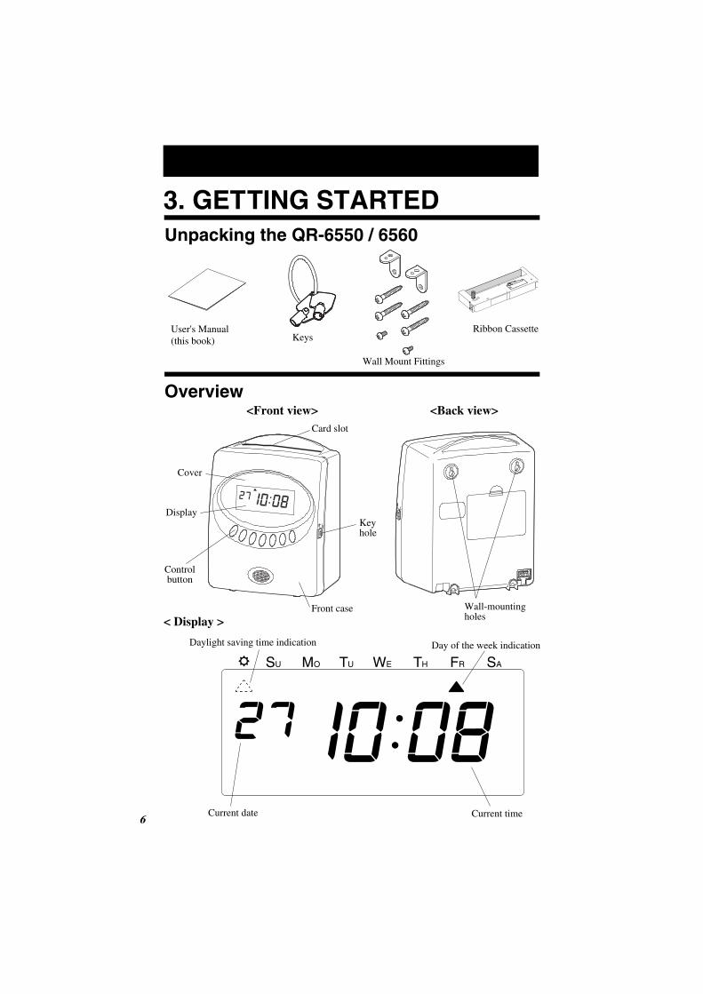
Overview<Front view> <Back view>
3. GETTING STARTEDUnpacking the QR-6550 / 6560
User's Manual(this book)
Wall Mount Fittings
Ribbon CassetteKeys
< Display >
Key hole
Front case
Cover
Display
Control button
Card slot
Wall-mountingholes
6 2
Daylight saving time indication Day of the week indication
Current date Current time
SU MO TU WE TH FR SA
Make sure the power is on before installing.
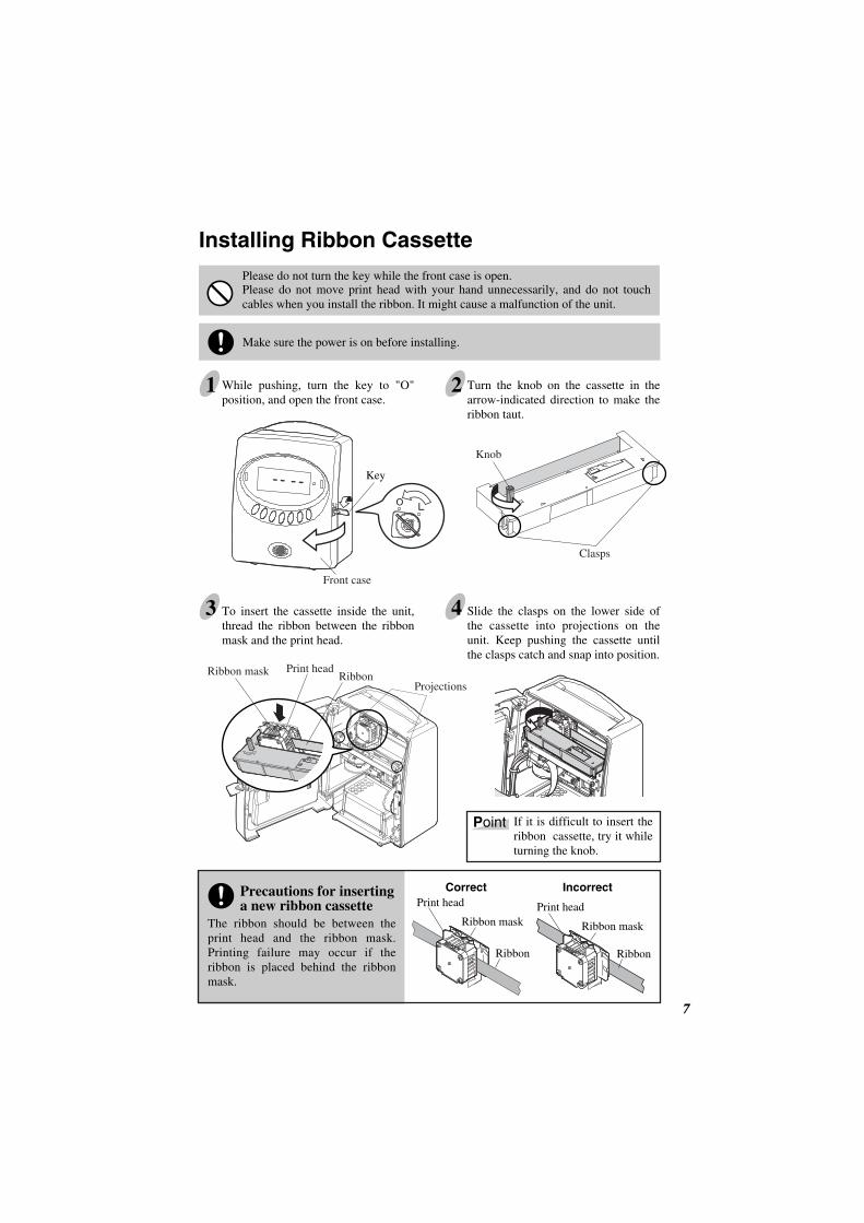
The ribbon should be between the print head and the ribbon mask. Printing failure may occur if the ribbon is placed behind the ribbon mask.
7 7
Installing Ribbon Cassette
1 While pushing, turn the key to "O" position, and open the front case.
2 Turn the knob on the cassette in the arrow-indicated direction to make the ribbon taut.
4 Slide the clasps on the lower side of the cassette into projections on the unit. Keep pushing the cassette until the clasps catch and snap into position.
If it is difficult to insert the ribbon cassette, try it while turning the knob.
3 To insert the cassette inside the unit, thread the ribbon between the ribbon mask and the print head.
Front case
Knob
Projections
Print headRibbon
Please do not turn the key while the front case is open.Please do not move print head with your hand unnecessarily, and do not touch cables when you install the ribbon. It might cause a malfunction of the unit.
Key
Print head
Ribbon mask
Ribbon
Correct Incorrect
Print head
Ribbon mask
Ribbon
Clasps
Ribbon mask
Precautions for inserting a new ribbon cassette
Point
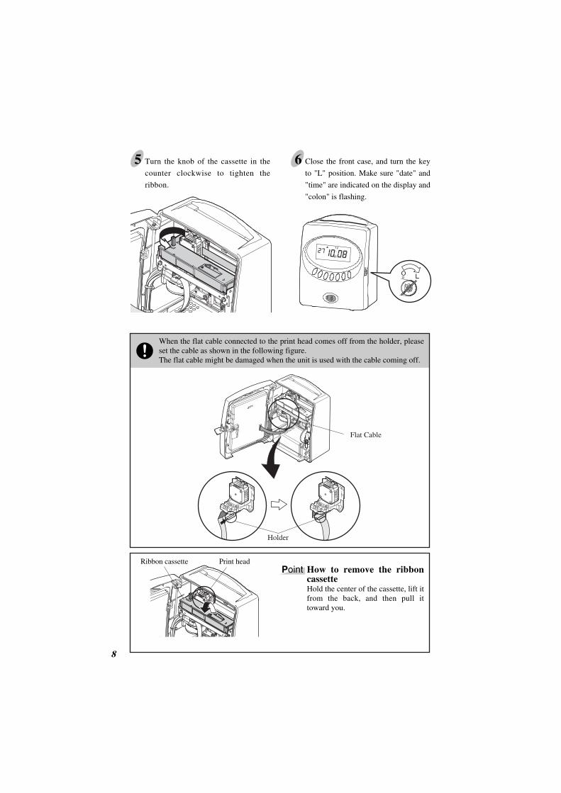
65 Close the front case, and turn the key
to "L" position. Make sure "date" and
"time" are indicated on the display and
"colon" is flashing.
Turn the knob of the cassette in the
counter clockwise to tighten the
ribbon.
8 2
When the flat cable connected to the print head comes off from the holder, please set the cable as shown in the following figure.The flat cable might be damaged when the unit is used with the cable coming off.
Flat Cable
Ribbon cassette Print headHow to remove the ribbon cassetteHold the center of the cassette, lift it from the back, and then pull it toward you.
Point
Holder
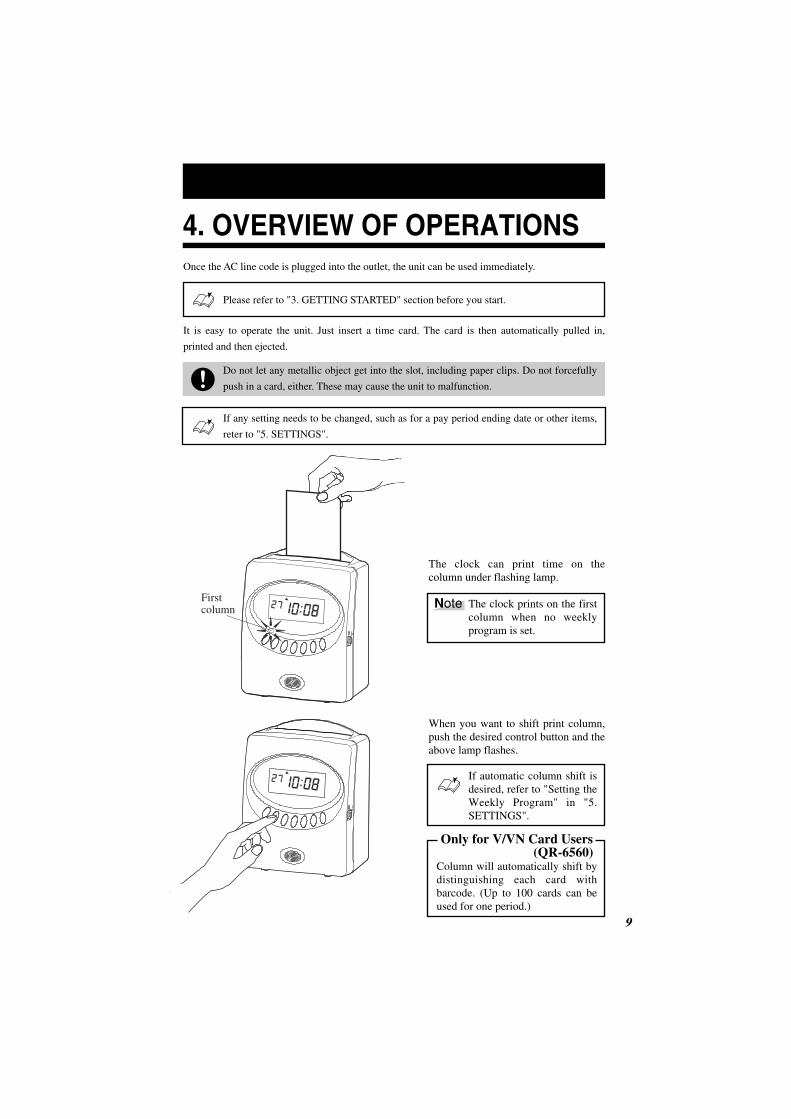
4. OVERVIEW OF OPERATIONSOnce the AC line code is plugged into the outlet, the unit can be used immediately.
Please refer to "3. GETTING STARTED" section before you start.
It is easy to operate the unit. Just insert a time card. The card is then automatically pulled in,
printed and then ejected.
Do not let any metallic object get into the slot, including paper clips. Do not forcefully
push in a card, either. These may cause the unit to malfunction.
If any setting needs to be changed, such as for a pay period ending date or other items,
reter to "5. SETTINGS".
10 9
The clock can print time on the column under flashing lamp.
The clock prints on the first column when no weekly program is set.
When you want to shift print column, push the desired control button and the above lamp flashes.
Only for V/VN Card Users (QR-6560)
Column will automatically shift by distinguishing each card with barcode. (Up to 100 cards can be used for one period.)
If automatic column shift is desired, refer to "Setting the Weekly Program" in "5. SETTINGS".
Note Firstcolumn
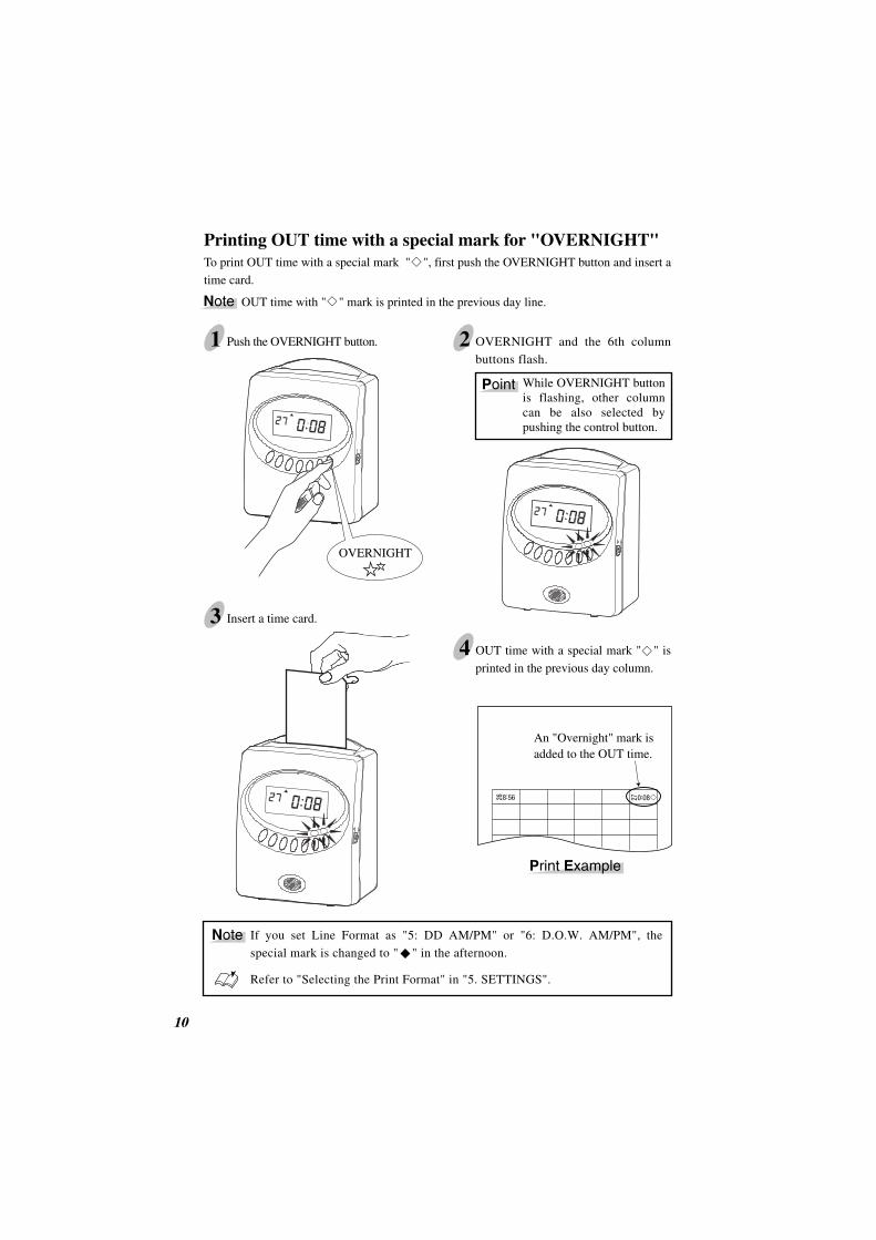
Printing OUT time with a special mark for "OVERNIGHT"To print OUT time with a special mark " ", first push the OVERNIGHT button and insert a
time card.
OUT time with " " mark is printed in the previous day line.
10 2
1 Push the OVERNIGHT button. 2 OVERNIGHT and the 6th column
buttons flash.
While OVERNIGHT button is flashing, other column can be also selected by pushing the control button.
3 Insert a time card.
4 OUT time with a special mark " " is
printed in the previous day column.
If you set Line Format as "5: DD AM/PM" or "6: D.O.W. AM/PM", the
special mark is changed to " " in the afternoon.
Refer to "Selecting the Print Format" in "5. SETTINGS".
An "Overnight" mark is added to the OUT time.
Note
Note
OVERNIGHT
Point
Print Example

5. SETTINGSPreparation for Settings
Make sure the power is on before making setting.
12 11
1 Put your fingers in the depressions at the lower side of the cover, and pull it toward you.
2 While pushing, turn the key to "O" position. At that moment, display will be as shown in the following figure. Then, you can go into the setting mode.
Refer to the following pages for details of each setting.
4 Replace the cover. At that time, make sure to fit the tabs at the both side of the cover into the holes on the unit.
3 After the setting has been completed, push the SETTING END button to get out of the setting mode. Turn the key to "L" position. Make sure "date" and "time" are indicated on the display and colon is flashing.
Display
Holes
Tabs
SETTING END
Key
Depressions

Overview of Control Buttons
DATE/TIME button
Use the DATE/TIME button when you want to change the date and/or time.
(Make sure to push it for 1 second before going to setting mode.)
FUNCTION button
Use the FUNCTION button when you want to change the pay period, print format, and so
on. (Make sure to push it for 1 second before going to setting mode.)
+ or - button
When you push the + or - button, you can change the set value.
SET button
You can set the value selected on the display by pushing the SET button.
SETTING END button
Push this button when you get out of the setting mode.
12 2
Control Buttons

14 13
Selecting the Hour Display Format
1 Push the DATE/TIME button for 1 second and position the " " under the "DISPLAY HOURS" mark.
2 In case of the example, push the + or - button to set at "1" and then push the SET button. At that moment, display will stop flashing and the setting is now completed.
3 Push the SETTING END button to get out of the setting mode.Turn the key to "L" position. Make sure "date" and "time" are indicated on the display and colon is flashing. Then replace the cover.
DISPLAYHOURS
DISPLAYHOURS
AM
Colon
Date
DATE / TIME SET
DATE / TIME SET
Before you start setting, make sure to see "Preparation for Setting".
You can select desired hour display format from following 2 options.
The clock default is "2: 24 Hour".
Order options1. AM / PM 2. 24 Hour
Example Change the format to "1: AM / PM".
14 15
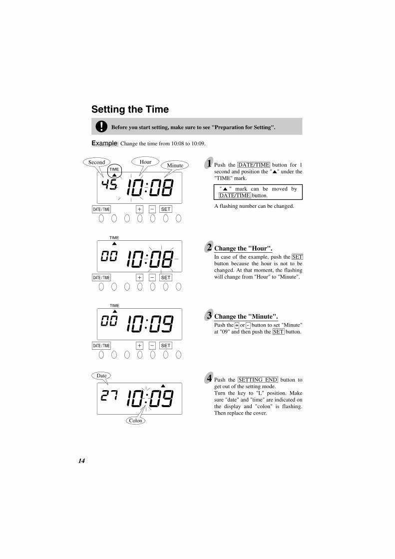
Setting the Time
1 Push the DATE/TIME button for 1 second and position the " " under the "TIME" mark.
" " mark can be moved by DATE/TIME button.
A flashing number can be changed.
2In case of the example, push the SET button because the hour is not to be changed. At that moment, the flashing will change from "Hour" to "Minute".
Change the "Hour".
3Push the + or - button to set "Minute" at "09" and then push the SET button.
4 Push the SETTING END button to get out of the setting mode.Turn the key to "L" position. Make sure "date" and "time" are indicated on the display and "colon" is flashing. Then replace the cover.
TIME
TIME
MinuteSecond Hour
Date
Colon
TIME
Before you start setting, make sure to see "Preparation for Setting".
Example Change the time from 10:08 to 10:09.
Change the "Minute".
DATE / TIME SET
DATE / TIME SET
DATE / TIME SET

16 15
Setting the Date
1 Push the DATE/TIME button for 1 second and position the " " under the "DATE" mark.
" " mark can be moved by DATE/TIME button.
A flashing number can be changed.
2In case of the example, push the SET button because the year 2006 is not to be changed. At that moment, the flashing will change from "Year" to "Month".
Change the "Year".
3In case of the example, push the SET button because the month of October is not to be changed. At that moment, the flashing will change from "Month" to "Date".
Before you start setting, make sure to see "Preparation for Setting".
Example Change the date from Oct. 26, 2006 to Oct. 27, 2006.
Change the "Month".
4Push the + or - button to set "Date" at "26" and then push the SET button.At that moment, the display will stop flashing, and the setting is now completed.
5 Push the SETTING END button to get out of the setting mode.Turn the key to "L" position. Make sure "date" and "time" are indicated on the display and "colon" is flashing. Then replace the cover.
Change the "Date".
DATE
DATE
DATE
DATE
Date
Colon
Year MonthDate
DATE / TIME SET
DATE / TIME SET
DATE / TIME SET
DATE / TIME SET

The card type can be selected from the following six options.
16 17
Selecting the Card Type
1. V/VN Card*1
2. S Card3. Weekly Card4. Bi-weekly Card5. Other A Card*2
6. Other B Card*3
Monthly, both sides / Weekly, one side / Bi-weekly, one sideMonthly, both sidesWeekly, one sideBi-weekly, one sideMonthly, both sidesMonthly, both sides
--------
1 to 32 1 to 32
Blank LineCard TypeOrder Options
The clock default is "16"
Please refer to "13. TIME CARD SPECIFICATIONS".
To make sure pay period ending date ···
Refer to "Setting Pay Period Ending Date/Day".
The clock default is "2: S Card".*1. V/VN card is available only with QR-6560.
*2. Automatic differentiation of the front and back.
*3. Without automatic differentiation of the front and back.
Blank Line
Front side Back side
15 lines
123456789
10111213141516
17181920212223242526272829303132
16 lines
"Blank Line" setting is available if you select "5: Other A Card" or "6: Other B Card".Blank Line is originally set at "16" (the last line on the front side). If you use a time card with a different line format, you can change the printing line by setting blank line.
When you select "1: V/VN Card", the clock will remember the last imprint and automatically switch the "IN" and "OUT" columns by distinguishing each card with barcode. (Up to 100 cards can be used for one period.)
Example The first line is blank on the back (blank line: 17).
Card Number
Barcode
001
Signature
DEPT.
NO. NAME
Note You can not print in the 1st column bycontrol button after pringing in the 2nd column.
Only for V/VN Card Users (QR-6560)
Only for Other A Card / Other B Card Users
You can select the desired pay period (Monthly, Weekly or Bi-weekly). Refer to "Setting Pay Period Ending Date/Day".
16 17
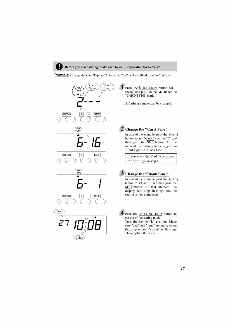
1 Push the FUNCTION button for 1 second and position the " " under the "CARD TYPE" mark.
A flashing number can be changed.
2In case of the example, push the + or - button to set "Card Type" at "6" and then push the SET button. At that moment, the flashing will change from "Card Type" to "Blank Line".
If you select the Card Type except
"5" or "6", go on step 4.
CARDTYPE
CARDTYPE
CardType
BlankLine
Before you start setting, make sure to see "Preparation for Setting".
SETFUNCTION
SETFUNCTION
Example Change the Card Type to "6: Other A Card" and the Blank Line to "1st line".
Change the "Card Type".
3In case of the example, push the + or - button to set at "1" and then push the SET button. At that moment, the display will stop flashing, and the setting is now completed.
4
CARDTYPE
Date
Colon
SETFUNCTION
Change the "Blank Line".
Push the SETTING END button to get out of the setting mode.Turn the key to "L" position. Make sure "date" and "time" are indicated on the display and "colon" is flashing. Then replace the cover.

Monthly/Weekly/Bi-weekly
This function is available if you select "monthly card" in the card type setting.
18 2
Setting Pay Period Ending Date/Day
1 Push the FUNCTION button for 1 second and position the " " under the "PAY PERIOD" mark.
" " mark can be moved by FUNCTION button.
A flashing number can be changed.*For V/VN Card Users, refer to below "How
to set the Pay Period".
2 In case of the example, push the + or - button to set "Ending Date" at "20", and then push the SET button. At that moment, the display will stop flashing and the setting is now completed.
3 Push the SETTING END button to get out of the setting mode.Turn the key to "L" position. Make sure "date" and "time" are indicated on the display and "colon" is flashing. Then replace the cover.
PAY PERIOD
PAY PERIOD
Ending Date
Date
Colon
Before you start setting, make sure to see "Preparation for Setting".
Example Change the Pay Period Ending Date to the 20th.
The clock default is "31".
SETFUNCTION
PAY PERIOD
Ending DatePay Period
SETFUNCTION
How to set the pay periodYou can select "Pay Period" by the + or - buttons, and push the SET button.At that moment, the flashing will change to "Ending Date (/Day)", and then go on Step 2.
Only for V/VN Card Users (QR-6560)
Pay Period1. Monthly 2. Weekly3. Bi-Weekly

This function is available if you select "weekly card" in the card type setting.
You can set the desired day, which comes within a week from today. The pay period ending
date is the number of days from the date you are setting the clock.
The clock default is "0 (today)".
20 19
Monthly/Weekly/Bi-weekly
Assume that today is Friday, September 22, 2006 and the ending day is Sunday. As illustrated in the left figure, ending day (Sunday) is two days after.
1 Push the FUNCTION button for 1 second, and position the " " under the "PAY PERIOD" mark.
" " mark can be moved by FUNCTION button.
A flashing number can be changed.*For V/VN Card Users, refer to "How to set
the Pay Period" in "Monthly" setting (p.18).
2 Push the + or - button to set "Ending Day" at "2" and then push the SET button. At that moment, the display will stop flashing and the setting is now completed.
3 Push the SETTING END button to get out of the setting mode.Turn the key to "L" position. Make sure "date" and "time" are indicated on the display and "colon" is flashing. Then replace the cover.
PAY PERIOD
Ending Day
PAY PERIOD
Date
Colon
Today
September 22
Friday
······ ·· ·····
Ending day
September 24 ···
Sunday
September 23
Saturday
10 2
Example
SETFUNCTION
SETFUNCTION
Before you start setting, make sure to see "Preparation for Setting".
Pay Period1. Monthly2. Weekly3. Bi-Weekly

This function is available if you select "bi-weekly card" in the card type setting.
You can set the desired day, which comes within two weeks from today. The pay period
ending date is the number of days from the date you are setting the clock.
The clock default is "0 (today)".
20 2
Monthly/Weekly/Bi-weekly
Assume that today is Friday, September 15, 2006 and the ending day is Sunday the week after next. As illustrated in the left figure, ending day (Sunday) is nine days after.
1 Push the FUNCTION button for 1 second, and position the " " under the "PAY PERIOD" mark.
" " mark can be moved by FUNCTION button.
A flashing number can be changed.*For V/VN Card Users, refer to "How to set
the Pay Period" in "Monthly" setting (p.18).
2 Push the + or - button to set "Ending Day" at "9" and then push the SET button. At that moment, the display will stop flashing and the setting is now completed.
3 Push the SETTING END button to get out of the setting mode.Turn the key to "L" position. Make sure "date" and "time" are indicated on the display and "colon" is flashing. Then replace the cover.
Date
Colon
Example
PAY PERIOD
Ending Day
PAY PERIOD
Today
September 15
Friday
···· ·· ·····
··············
·············· ··············
····
Ending day
September 24·····
Sunday
September 16
Saturday
September 19
Saturday
10 8 9
SETFUNCTION
SETFUNCTION
Before you start setting, make sure to see "Preparation for Setting".
Pay Period1. Monthly2. Weekly 3. Bi-Weekly

The Day Advance Time refers to the time when printing shifts to the next line on a time card for the next day. This function enables the punch out time record to print on the same line of the previous working day even if leaving time is after midnight. The clock default is "5:00".
21 21
Setting the Day Advance Time
1
In case of the example, push the + or - button to set the hour at "7" and then push the SET button. At that moment, the flashing will change from "Hour" to "Minute".
In case of the example, push the SET button because the minute is not to be changed. At that moment, the display will stop flashing and the setting is now completed.
4 Push the SETTING END button to get out of the setting mode.Turn the key to "L" position. Make sure "date" and "time" are indicated on the display and "colon" is flashing. Then replace the cover.
DAY ADVANCE TIME
DAY ADVANCE TIME
Date
Colon
DAY ADVANCE TIME
MinuteHour
Before you start setting, make sure to see "Preparation for Setting".
Example Change the Day Advance Time from 5:00 to 7:00.
Push the FUNCTION button for 1 second, and position the " " under the "DAY ADVANCE TIME" mark.
" " mark can be moved by FUNCTION button.
A flashing number can be changed.SETFUNCTION
SETFUNCTION
SETFUNCTION
2 Change the "Hour".
3 Change the "Minute".

2
Selecting the Print Format
Minute Type
1
2In case of the example, push the + or - button to set "Line Format" at "5" and then push the SET button. At that moment, the flashing will change to "Minute Type".
SETFUNCTION
SETFUNCTION
Order options Print Example: 8:341. 1/602. 1/100
8: 348. 57
1. DD 24HR2. D.O.W. 24HR3. 24HR Large Font4. AM/PM5. DD AM/PM6. D.O.W AM/PM
21 15 : 30Mo 15 : 3015 : 30Pm 3 : 3021 3 : 30 PMo 3 : 30 P
date, 24hour, minuteday of the week, 24hour, minute24hour, minute12hour, minutedate, 12hour, minuteday of the week, 12hour, minute
Print Example:Monday, 21, 3:30 p.m.Line FormatOrder Options
PRINTFORMAT
PRINTFORMAT
Line FormatMinute Type
Before you start setting, make sure to see "Preparation for Setting".
Line Format
Example Change the Line Format to "5: DD AM/PM" and the Minute Type to "2: 1/100" min.
Print Example 21 3. 50 P (Monday, 21, 15:30)
You can select desired Line Format (6 types) and Minute Type (2 types).
The clock default is "1: DD 24HR".
The clock default is "1: 1/60".
4 Push the SETTING END button to get out of the setting mode.Turn the key to "L" position. Make sure "date" and "time" are indicated on the display and "colon" is flashing. Then replace the cover.
PRINTFORMAT
SETFUNCTION
Push the FUNCTION button for 1 second and position the " " under the "PRINT FORMAT" mark.
" " mark can be moved by FUNCTION button.
A flashing number can be changed.
Select the "Line Format".
3In case of the example, push the + or - button to set "Minute Type" at "2" and then push the SET button. At that moment, the display will stop flashing and the setting is now completed.
Select the "Minute Type".
Date
Colon22
24 23
Selecting the Language
3
SETFUNCTION
SETFUNCTION
Date
Colon
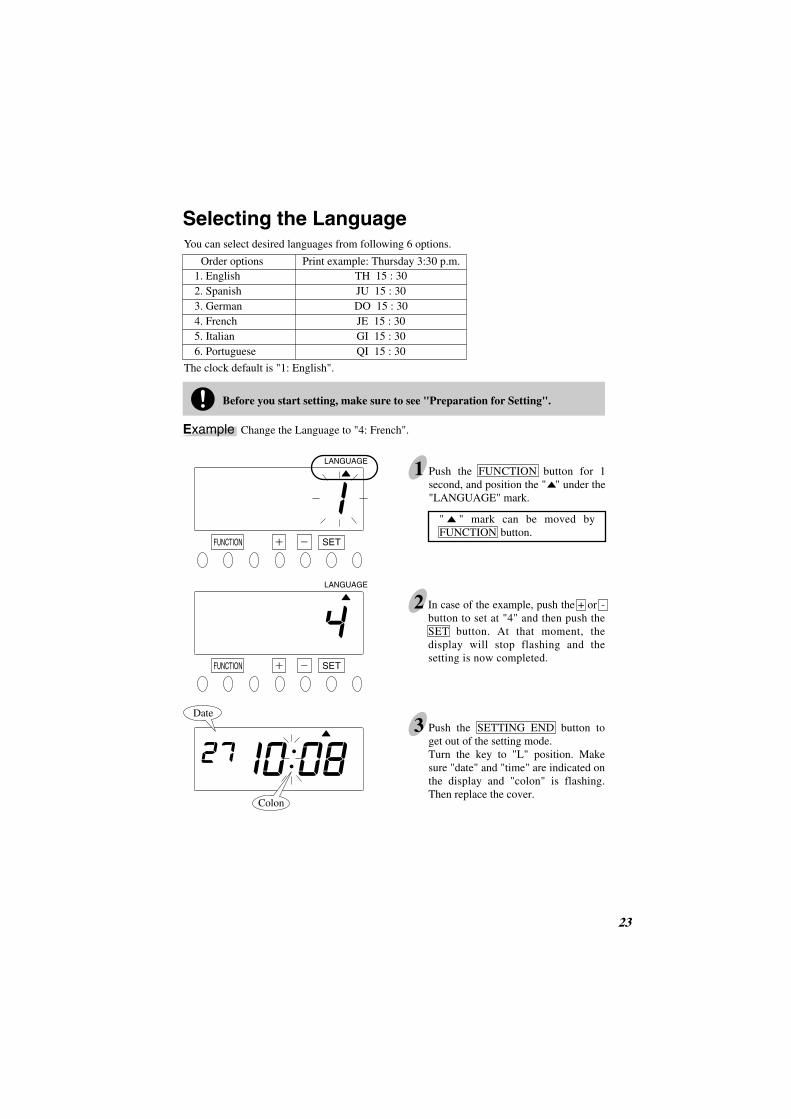
Order options Print example: Thursday 3:30 p.m.1. English2. Spanish3. German4. French5. Italian6. Portuguese
TH 15 : 30JU 15 : 30DO 15 : 30JE 15 : 30GI 15 : 30QI 15 : 30
LANGUAGE
2
1
LANGUAGE
Before you start setting, make sure to see "Preparation for Setting".
You can select desired languages from following 6 options.
The clock default is "1: English".
Example Change the Language to "4: French".
In case of the example, push the + or - button to set at "4" and then push the SET button. At that moment, the display will stop flashing and the setting is now completed.
Push the SETTING END button to get out of the setting mode.Turn the key to "L" position. Make sure "date" and "time" are indicated on the display and "colon" is flashing. Then replace the cover.
Push the FUNCTION button for 1 second, and position the " " under the "LANGUAGE" mark.
" " mark can be moved by FUNCTION button.
Setting the Daylight Saving Time
Daylight saving time function
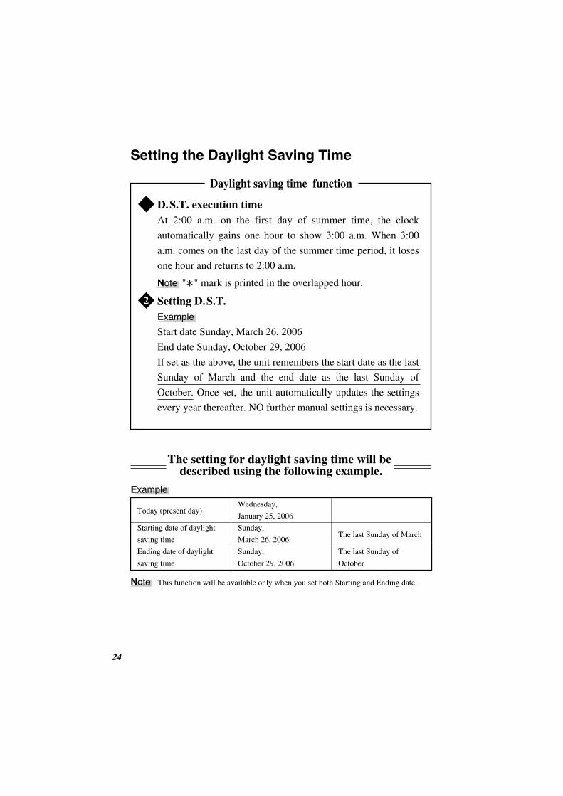
D.S.T. execution timeAt 2:00 a.m. on the first day of summer time, the clock
automatically gains one hour to show 3:00 a.m. When 3:00
a.m. comes on the last day of the summer time period, it loses
one hour and returns to 2:00 a.m.
Setting D.S.T.Example
Start date Sunday, March 26, 2006
End date Sunday, October 29, 2006
If set as the above, the unit remembers the start date as the last
Sunday of March and the end date as the last Sunday of
October. Once set, the unit automatically updates the settings
every year thereafter. NO further manual settings is necessary.
1
2
The setting for daylight saving time will be described using the following example.
Today (present day)
Starting date of daylight
saving time
Ending date of daylight
saving time
Wednesday,
January 25, 2006
Sunday,
March 26, 2006
Sunday,
October 29, 2006
The last Sunday of March
The last Sunday of
October
24
Example
Note This function will be available only when you set both Starting and Ending date.
Note " " mark is printed in the overlapped hour.

2
" " mark means "starting date".
SU
26 25
DAYLIGHTSAVINGTIME
SETFUNCTION
SETFUNCTION
SETFUNCTION
SETFUNCTION
DAYLIGHTSAVINGTIME
DAYLIGHTSAVINGTIME
DAYLIGHTSAVINGTIME
DAYLIGHTSAVINGTIME
Month DateYear
Setting the Starting Date of Daylight Saving Time
Before you start setting, make sure to see "Preparation for Setting".
1 Push the FUNCTION button for 1 second, and position the " " next to the "DAYLIGHT SAVING TIME" mark.
" " mark can be moved by FUNCTION button.
A flashing number can be changed.
In case of the example, push the SET button because the hour is not to be changed. At that moment, the flashing will change from "Yaer" to "Month".
Change the "Year".
3Push the + or - button to set at "3" and push the SET button.At that moment, the flashing will change from "Month" to "Date".
Change the "Month".
4Push the + or - button to set at "26" and then push the SET button. At that moment, the display will stop flashing and the " " is displayed under "SU".Now the starting date of D.S.T. setting has been completed.
Go on "Setting The Ending Date of Daylight Saving Time".
Change the "Date".

5
26 49
SETFUNCTION
Setting the Ending Date of Daylight Saving Time
Next, push the SET button. At that moment, the flashing will change "Year" to "Month".
Change the "Year".
6Push the + or - button to set at "10" and then push the SET button. At that moment, the flashing will change from "Month" to "Date".
Change the "Month".
7Push the + or - button to set at "29" and then push the SET button. At that moment, the display will stop flashing and the " " mark is displayed under "SU". Now the ending date of D.S.T. setting has been completed.
8 Push the SETTING END button to get out of the setting mode.Turn the key to "L" position. Make sure "date" and "time" are indicated on the display and "colon" is flashing. Then replace the cover.
Change the "Date".
" " mark means "ending date".
Date
Colon
SU
DAYLIGHTSAVINGTIME
DAYLIGHTSAVINGTIME
SETFUNCTION
DAYLIGHTSAVINGTIME
SETFUNCTION
Month DateYear

2
28 27
Deleting the Daylight Saving Time Settings
1 Push the FUNCTION button for 1 second, and position the " " next to the "DAYLIGHT SAVING TIME"mark.
" " mark can be moved by FUNCTION button.
A flashing number can be changed.
Push the SET button and then the flashing will change from "Year" to "Month". Next, push the + or - button to set at " ".
3Push the SET button. This cancels the daylight saving time settings.
4 Push the SETTING END button to get out of the setting mode.Turn the key to "L" position. Make sure "date" and "time" are indicated on the display and "colon" is flashing. Then replace the cover.
Point To delete and cancel the daylight saving time settings, change the display of "Month" of the starting date to " ".
Example To change March 26, 2006 of "starting date" and delete daylight saving time settings.
DAYLIGHTSAVINGTIME
DAYLIGHTSAVINGTIME
DAYLIGHTSAVINGTIME
SU
SETFUNCTION
SETFUNCTION
SETFUNCTION
Before you start setting, make sure to see "Preparation for Setting".
Delete the "Month".
Cancel the "D.S.T. Settings".
MonthYear
Date
Colon

Setting the Weekly Program
Weekly Programs enable the clock to memorize the following functions for specified time
periods. Times are always printed in 1st Column for the time period unless any program for
print column is set.
28 2
1.
2.
Automatic IN/OUT printing column shift
Special mark " " for irregular recognition
Function No. Function
Monday-Friday
Program No.1No setting
05:00Day advance time Next day
09:00 12:00 17:30 05:00
Program No.2 Program No.3
Sunday & Saturday
Program No.4
05:00Day advance time Next day
12:00 05:00
Program No.5
12345
Mon.-Fri. Mon.-Fri. Mon.-Fri. Sun.& Sat. Sun.& Sat.
23456
OnOnOffOnOn
9:0012:0017:305:00
12:00
QR-6550
The time table program is explained using the following example.
Example
1st Column 2nd Column 3rd Column 4th Column
6th Column5th Column
' ' on
' ' on
PrintIrregular Mark
PrintColumnProgram No. Day of the Week Time
Time table
Note Up to 48 programs can be set.
Note One programmed day begins at the day advance time. Refer to "Setting Day Advance Time" in the section of this manual.

QR-6550
The following is the print example based on the case of the previous page.
Date D.O.W.21st Thu.22nd Fri.23rd Sat.24th Sun25th Mon.
29th Fri.
16 29
8:46
8:50
8:46A
11:53
9:06
10:29
14:10
2:30
17:48
19:22
17:51
6:03P
9:22 17:50
Print Example
Note If you set "Line Format" as "5: DD AM/PM" or "6: D.O.W. AM/PM", the
irregular mark is changed to " " in the afternoon.
For setting "Line Format", please refer to "Selecting the Print Format".
2122
29
2225
29
2229
2221
2529
2323

QR-6550
30 00
1
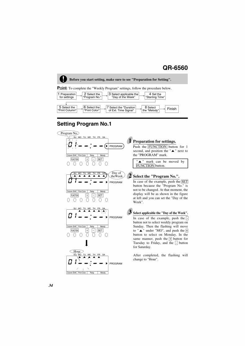
2In case of the example, push the SET button because the "Program No." is not to be changed. At that moment, the display will be as shown in the figure at left and you can set the "Day of the week".
3In case of the example, push the - button not to select weekly program on Sunday. Then the flashing will move to " " under "MO", and push the + button to select on Monday. In the same manner, push the + button for Tuesday to Friday, and the - button for Saturday.
After completed, the flashing will change to "Hour".
Select applicable the "Day of the Week".
PROGRAM
PROGRAM
PROGRAM
PROGRAM
SETFUNCTION
Column Shift Mark
SU MO TU WE TH FR SA
SETFUNCTION
Column Shift Mark
SU MO TU WE TH FR SA
SU MO TU WE TH FR SA
SETFUNCTION
Column Shift Mark
SU MO TU WE TH FR SA
Day of the Week
Push the FUNCTION button for 1 second, and position the " " next to the "PROGRAM" mark.
" " mark can be moved by FUNCTION button.
1 Preparationfor settings
2 Select the"Program No."
3 Select applicable the"Day of the Week"
4 Set the"Starting time"
5 Select the"Print Column"
6 Select the"Print Irregular Mark" Finish
Setting Program No.1
Before you start setting, make sure to see "Preparation for Setting".
Program No.
To complete the "Weekly Program" settings, follow the procedure below.Point
Preparation for settings.
Hour
Select the "Program No.".
SU MO TU WE TH FR SA
QR-6550
00 31
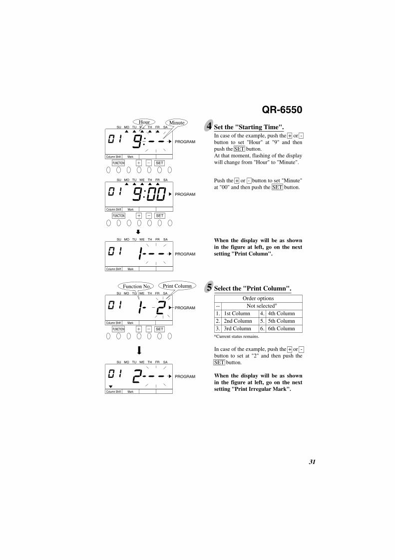
4In case of the example, push the + or - button to set "Hour" at "9" and then push the SET button. At that moment, flashing of the display will change from "Hour" to "Minute".
Push the + or - button to set "Minute" at "00" and then push the SET button.
When the display will be as shown in the figure at left, go on the next setting "Print Column".
Set the "Starting Time".
PROGRAM
PROGRAM
PROGRAM
MinuteHour
Column Shift Mark
SU MO TU WE TH FR SA
SETFUNCTION
Column Shift Mark
SU MO TU WE TH FR SA
SETFUNCTION
Column Shift Mark
5
In case of the example, push the + or - button to set at "2" and then push the SET button.
When the display will be as shown in the figure at left, go on the next setting "Print Irregular Mark".
Select the "Print Column".
PROGRAM
Print ColumnFunction No.
PROGRAM
SETFUNCTION
Column Shift Mark
SU MO TU WE TH FR SA
Column Shift Mark
SU MO TU WE TH FR SA
Order optionsNot selected*
1st Column2nd Column3rd Column
--1.2.3.
4th Column5th Column6th Column
4.5.6.
*Current status remains.

QR-6550
32 00
Push the + button and the "Program No." will start flashing.Push the + button once again to set the Program No. at "2".
Make settings for Program No.2-5 in the same manner as for program No.1.
When all the programs are set, push the SETTING END button to get out of the setting mode.Turn the key to "L" position. Make sure "date" and "time" are indicated on the display and colon is flashing. Then replace the cover.
Setting the Program No.2-5
6
In case of the example, push the + or -button to set at "1"and push the SET button.
At that moment, the display will be as shown in the figure at left and the setting of "Program No.1" has been completed.Then you can proceed "Setting the Program No.2".
Order options
Not selected*
Mark onMark off
--1.2.PROGRAM
Function No.
PROGRAM
PROGRAM
PROGRAM
Select the "Print Irregular Mark".
SETFUNCTION
Column Shift Mark
SU MO TU WE TH FR SA
Column Shift Mark
SU MO TU WE TH FR SA
SETFUNCTION
Column Shift Mark
SU MO TU WE TH FR SA
Column Shift Mark
SU MO TU WE TH FR SA
Program No.
End Setting
Date
Colon
Print Irregular Mark
*Current status remains.

Weekly Programs enable the clock to memorize the following functions for specified time
periods. Times are always printed in 1st Column for the time period unless any program for
print column is set.
7 33
Setting the Weekly Program QR-6560
Monday-Saturday Print in Black /in 1st Column
Print in Red /in 2nd Column
Print in Red /in 3rd Column
Print in Black /in 4th Column
Program No.1No setting
05:00Day advance time Next day
09:00 12:00 17:30 05:00
Program No.2 Program No.3
Sunday & Saturday Print in Red/in 5th Column
Program No.4
05:00Day advance time Next day
12:00 05:00
Program No.5
Melody Signal
Function No
1.
2.
3.
4.
Function
Automatic IN/OUT printing column shift
Automatic selection of print color (Black or Red)
Output signal for external signal
Playing melody*
12345
Mon.-Fri. Mon.-Fri. Mon.-Fri. Sun.& Sat. Sun.& Sat.
23456
For 10 seconds 9:0012:0017:30 5:0012:00
The time table program is explained using the following example.
Example
External TimeSignal
ProgramNo.
PrintColumn
RedRed
BlackRedRed
1
1
PrintColorDay of the Week Time Melody
Time table
Melody
Print in Red/in 6th Column
Note Up to 48 programs can be set. *You can preview each melody when setting it.
Note One programmed day begins at the day advance time. Refer to "Setting Day Advance Time" .
QR-6560
34 00
1
2
3 Select applicable the "Day of the Week".
Push the FUNCTION button for 1 second, and position the " " next to the "PROGRAM" mark.
" " mark can be moved by FUNCTION button.
1 Preparationfor settings
2 Select the"Program No."
3 Select applicable the"Day of the Week"
4 Set the"Starting Time"
5 Select the"Print Column"
6 Select the"Print Color" Finish
Setting Program No.1
Before you start setting, make sure to see "Preparation for Setting".
In case of the example, push the SET button because the "Program No." is not to be changed. At that moment, the display will be as shown in the figure at left and you can set the "Day of the Week".
In case of the example, push the - button not to select weekly program on Sunday. Then the flashing will move to " " under "MO", and push the + button to select on Monday. In the same manner, push the + button for Tuesday to Friday, and the - button for Saturday.
After completed, the flashing will change to "Hour".
PROGRAM
PROGRAM
PROGRAM
PROGRAM
SETFUNCTION
Column Shift Print Color Relay Melody
SETFUNCTION
Column Shift Print Color Relay Melody
SETFUNCTION
Column Shift Print Color Relay Melody
Column Shift Print Color Relay Melody
SU MO TU WE TH FR SA
SU MO TU WE TH FR SA
SU MO TU WE TH FR SA
SU MO TU WE TH FR SA
7 Select the "Duration of Ext. Time Signal"
8 Select the "Melody"
Day of theWeek
Hour
Preparation for settings.
Select the "Program No.".
To complete the "Weekly Program" settings, follow the procedure below.Point
Program No.

QR-6560
00 35
4 Set the "Starting Time".
5
In case of the example, push the + or - button to set at "2" and then push the SET button.
When the display will be as shown in the figure at left, go on the next setting "Print Color".
Select the "Print Column".
PROGRAM
Print ColumnFunction No.
PROGRAM
SETFUNCTION
Column Shift Print Color Relay Melody
SU MO TU WE TH FR SA
Column Shift Print Color Relay Melody
SU MO TU WE TH FR SA
SU MO TU WE TH FR SA
In case of the example, push the + or - button to set at "9" and then push the SET button. At that moment, flashing of the display will change from "Hour" to "Minute".
Push the + or - button to set "Minute" at "00" and then push the SET button.
When the display will be as shown in the figure at left, go on the next setting "Print Column".
PROGRAM
PROGRAM
PROGRAM
Minute
SETFUNCTION
Column Shift Print Color Relay Melody
SETFUNCTION
Column Shift Print Color Relay Melody
Column Shift Print Color Relay Melody
SU MO TU WE TH FR SA
SU MO TU WE TH FR SA
Hour
Order optionsNot selected*
1st Column2nd Column3rd Column
--1.2.3.
4th Column5th Column6th Column
4.5.6.
*Current status remains.
QR-6560
36 00
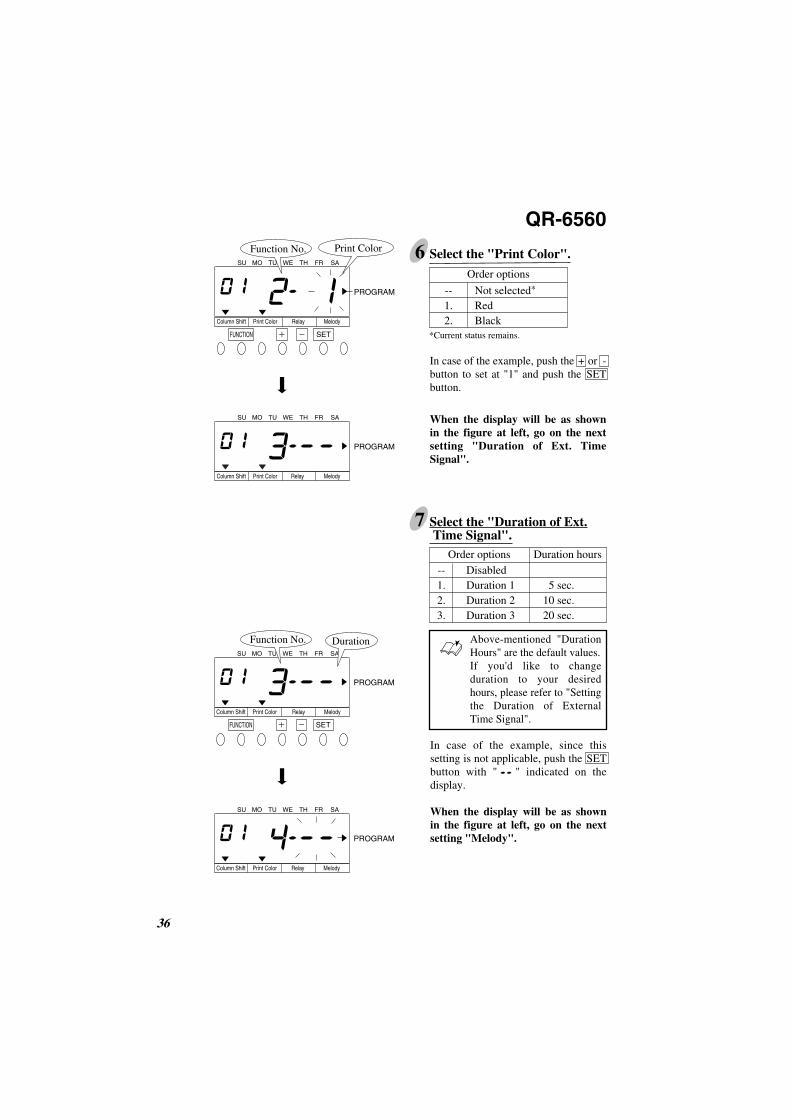
6Order options
Not selected*
RedBlack
--1.2.
Select the "Print Color".
7 Select the "Duration of Ext. Time Signal".
SU MO TU WE TH FR SA
In case of the example, since this setting is not applicable, push the SET button with " " indicated on the display.
When the display will be as shown in the figure at left, go on the next setting "Melody".
Above-mentioned "Duration Hours" are the default values.If you'd like to change duration to your desired hours, please refer to "Setting the Duration of External Time Signal".
In case of the example, push the + or - button to set at "1" and push the SET button.
When the display will be as shown in the figure at left, go on the next setting "Duration of Ext. Time Signal".
PROGRAM
Function No.
PROGRAM
PROGRAM
Function No.
PROGRAM
Order options Duration hoursDisabledDuration 1Duration 2Duration 3
5 sec.10 sec.20 sec.
--1.2.3.
Duration
SETFUNCTION
Column Shift Print Color Relay Melody
Column Shift Print Color Relay Melody
SETFUNCTION
Column Shift Print Color Relay Melody
Column Shift Print Color Relay Melody
Print ColorSU MO TU WE TH FR SA
SU MO TU WE TH FR SA
SU MO TU WE TH FR SA
*Current status remains.
QR-6560
32 37
Setting the Program No.2-5
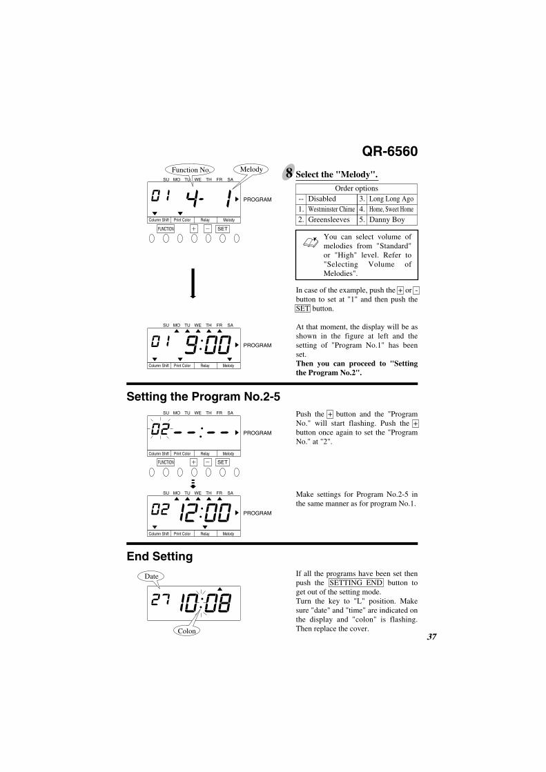
8 Select the "Melody".
End Setting
In case of the example, push the + or - button to set at "1" and then push the SET button.
At that moment, the display will be as shown in the figure at left and the setting of "Program No.1" has been set.Then you can proceed to "Setting the Program No.2".
Order optionsDisabledWestminster ChimeGreensleeves
--1.2.
Long Long AgoHome, Sweet HomeDanny Boy
3.4.5.
Push the + button and the "Program No." will start flashing. Push the + button once again to set the "Program No." at "2".
Make settings for Program No.2-5 in the same manner as for program No.1.
SU MO TU WE TH FR SA
PROGRAM
Function No.
PROGRAM
PROGRAM
PROGRAM
Melody
SETFUNCTION
Column Shift Print Color Relay Melody
Column Shift Print Color Relay Melody
SETFUNCTION
Column Shift Print Color Relay Melody
Column Shift Print Color Relay Melody
SU MO TU WE TH FR SA
SU MO TU WE TH FR SA
SU MO TU WE TH FR SA
If all the programs have been set then push the SETTING END button to get out of the setting mode.Turn the key to "L" position. Make sure "date" and "time" are indicated on the display and "colon" is flashing. Then replace the cover.
Date
Colon
You can select volume of melodies from "Standard" or "High" level. Refer to "Selecting Volume of Melodies".
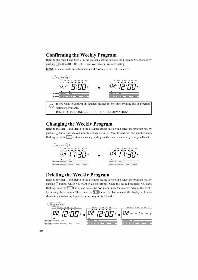
Confirming the Weekly ProgramRefer to the Step 1 and Step 2 in the previous setting section, the program No. changes by
pushing + button (01 02 03...) and you can confirm each setting.
38 00
Changing the Weekly ProgramRefer to the Step 1 and Step 2 in the previous setting section and select the program No. by
pushing + button, which you want to change settings. Once desired program number starts
flashing, push the SET button and change settings in the same manner as you originally set.
If you want to confirm all detailed settings in one time, printing list of program
settings is available.
Refer to "6. PRINTING LIST OF SETTING INFORMATION".
Deleting the Weekly ProgramRefer to the Step 1 and Step 2 in the previous setting section and select the program No. by
pushing + button, which you want to delete settings. Once the desired program No. starts
flashing, push the SET button and delete the " " mark under the selected "day of the week"
by pushing the - button. Then, push the SET button. At that moment, the display will be as
shown in the following figure and now program is deleted.
SU MO TU WE TH FR SA
Column Shift Mark
Column Shift
QR-6550
QR-6560 Print Color Relay Melody
Column Shift Mark
Column Shift Print Color Relay Melody
Column Shift Mark
Column Shift
QR-6550
QR-6560 Print Color Relay Melody
Column Shift Mark
Column Shift Print Color Relay Melody
Column Shift Mark
Column Shift Print Color Relay Melody
Column Shift Mark
Column Shift
QR-6550
QR-6560 Print Color Relay Melody
Column Shift Mark
Column Shift Print Color Relay Melody
SU MO TU WE TH FR SA
SU MO TU WE TH FR SA SU MO TU WE TH FR SA
SU MO TU WE TH FR SA SU MO TU WE TH FR SA SU MO TU WE TH FR SA
Program No.
Program No.
Program No.
Note You can confirm each function with " " mark on, if it is selected.
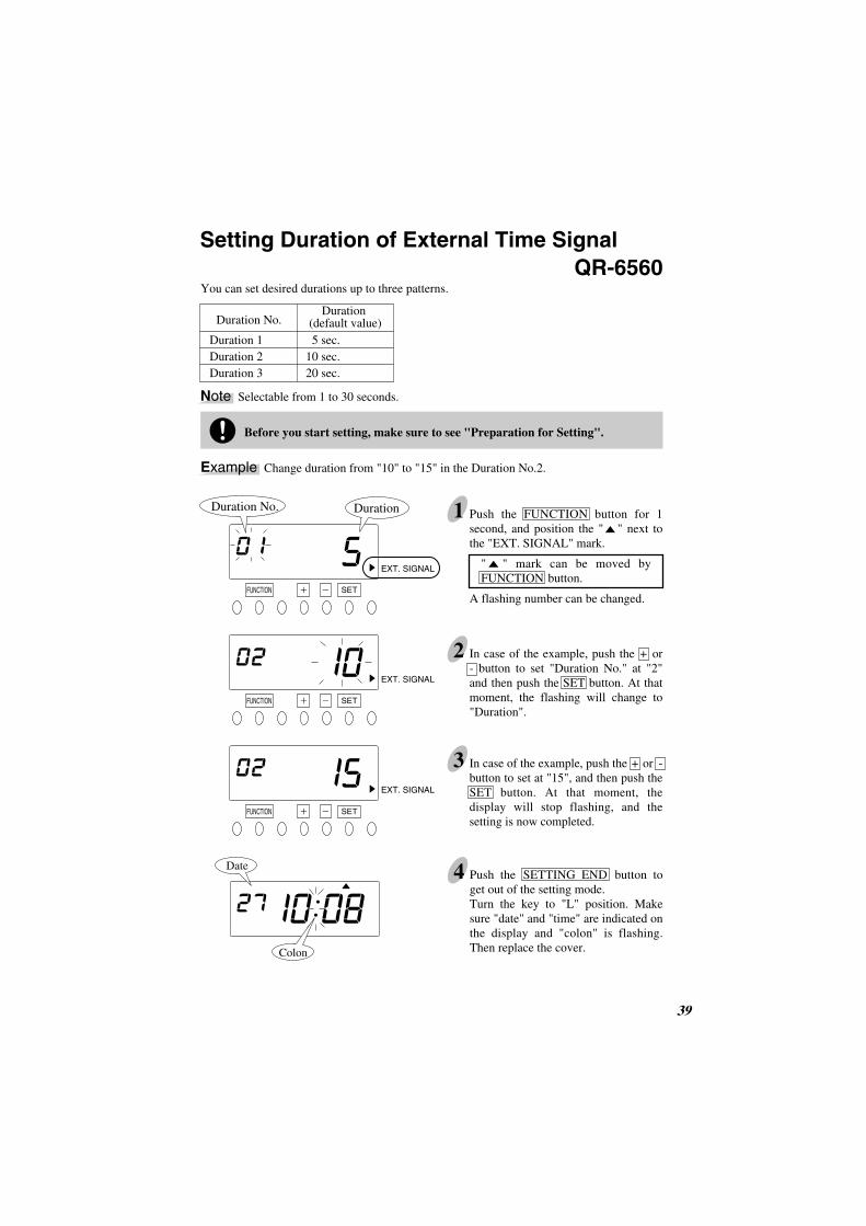
You can set desired durations up to three patterns.
9 39
Setting Duration of External Time Signal
2 In case of the example, push the + or - button to set "Duration No." at "2" and then push the SET button. At that moment, the flashing will change to "Duration".
3 In case of the example, push the + or - button to set at "15", and then push the SET button. At that moment, the display will stop flashing, and the setting is now completed.
SETFUNCTION
SETFUNCTION
SETFUNCTION
Duration No. Duration
EXT. SIGNAL
EXT. SIGNAL
EXT. SIGNAL
Duration No.Duration
(default value)Duration 1Duration 2Duration 3
5 sec.10 sec.20 sec.
Date
Colon
Before you start setting, make sure to see "Preparation for Setting".
Example Change duration from "10" to "15" in the Duration No.2.
1 Push the FUNCTION button for 1 second, and position the " " next to the "EXT. SIGNAL" mark.
" " mark can be moved by FUNCTION button.
A flashing number can be changed.
QR-6560
4 Push the SETTING END button to get out of the setting mode.Turn the key to "L" position. Make sure "date" and "time" are indicated on the display and "colon" is flashing. Then replace the cover.
Note Selectable from 1 to 30 seconds.

You can select volume of melodies from 2 levels.
40 2
Selecting Volume of Melodies
2 In case of the example, push the + or - button to set at "2" and then push the SET button. At that moment, the display will stop flashing, and the setting is now completed.
3 Push the SETTING END button to get out of the setting mode.Turn the key to "L" position. Make sure "date" and "time" are indicated on the display and "colon" is flashing. Then replace the cover.
Before you start setting, make sure to see "Preparation for Setting".
1 Push the FUNCTION button for 1 second, and position the " " over the "MELODY VOLUME" mark.
" " mark can be moved by FUNCTION button.
The clock default is "1: Standard".
Order Options1. Standard2. High
Example Change the volume level to "2: High".
MELODY VOLUME
SETFUNCTION
SETFUNCTION
MELODY VOLUME
Colon
Date
QR-6560

Once the password is set, you are requested to enter the current password before changing
any setting. If the password you entered does not coincide with the setting, you cannot
change the setting values.
You can select any 4-digit number from 0001 to 9998 as your password.
9 41
Setting the Password
1
4 Push the SETTING END button to get out of the setting mode.Turn the key to "L" position. Make sure "date" and "time" are indicated on the display and "colon" is flashing. Then replace the cover.
Colon
Date
PASSWORD
SETFUNCTION
SETFUNCTION
SETFUNCTION
PASSWORD
PASSWORD
Before you start setting, make sure to see "Preparation for Setting".
Example Set the password "1234".
2
1 Push the FUNCTION button for 1 second, and position the " " over the "PASSWORD" mark.
" " mark can be moved by FUNCTION button.
A flashing number can be changed.
In case of the example, push the + or - button to set at "12" and then push the SET button. At that moment, the flashing will change to the last two digits.
Set the first two digits.
3Next, push the + or - button to set at "34" and then push the SET button. At that moment, the display will stop flashing, and the setting is now completed.
Set the last two digits.
All settings must be reset if you forget the password. Refer to "7. RESETTING".
Note Numbers "0000" and "9999" are not valid as password.

Once the password is set, you are requested to enter the current password before changing
any setting.
42 2
How to Change Settings When the Password Is Set
1 Push the FUNCTION button for 1 second. Then, "9999" will be indicated on the display and the first two digits flash.
A flashing number can be changed.
2In case of the example, push the + or -button to set at "12" and then push the SET button. At that moment, the flashing will change to the last two digits.
3In case of the example, push the + or - button to set at "34" and then push the SET button. At that moment, the " " mark is located under "CARD TYPE".
4 Select desired setting mode by pushing the FUNCTION button. Then make any changes as explained.
If you want to change any "DATE/TIME" settings, push the DATE/TIME button in Step 1 instead. After entering the Password, the display will be as shown in the left figure and then make any changes as explained.
SET
DISPLAYHOURS
SETFUNCTION
SETFUNCTION
SETFUNCTION
Before you start setting, make sure to see "Preparation for Setting".
Example The current password is "1234" and go into the "FUNCTION" setting mode.
Enter the first two digits.
Enter the last two digits.
DATE / TIME
CARDTYPE
SETFUNCTION
Note

00 43
Canceling the Password
1 Push the FUNCTION button for 1 second and then enter the Password.
For entering Password, refer to Step 1 to 3 in "How to Change Settings When the Password Is Set" (previous page).
2 Position the " " over the "PASSWORD" mark. At that moment, the first two digits "12" flash.
" " mark can be moved by FUNCTION button.
PASSWORD
PASSWORD
SETFUNCTION
SETFUNCTION
SETFUNCTION
Before you start setting, make sure to see "Preparation for Setting".
Example The current password is "1234" and cancel it.
3 Push the + or - button to set at "00" for all digits and then push the SET button. At that moment, display will stop flashing and the setting is now completed.
To cancel the Password, the current one must be changed to "0000".Point
4 Push the SETTING END button to get out of the setting mode.Turn the key to "L" position. Make sure "date" and "time" are indicated on the display and "colon" is flashing. Then replace the cover.
Colon
Date
CARDTYPE
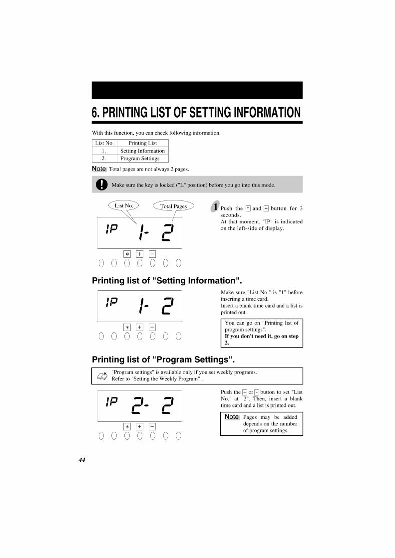
6. PRINTING LIST OF SETTING INFORMATIONWith this function, you can check following information.
Make sure "List No." is "1" before inserting a time card.Insert a blank time card and a list is printed out.
You can go on "Printing list of program settings".If you don't need it, go on step 2.
Push the + or - button to set "List No." at "2". Then, insert a blank time card and a list is printed out.
44 2
1 Push the * and + button for 3 seconds.At that moment, "IP" is indicated on the left-side of display.
Make sure the key is locked ("L" position) before you go into this mode.
Printing list of "Setting Information".
Printing list of "Program Settings".
List No. Printing List1. 2.
Setting InformationProgram Settings
List No. Total Pages
"Program settings" is available only if you set weekly programs.Refer to "Setting the Weekly Program" .
Note Total pages are not always 2 pages.
Pages may be added depends on the number of program settings.
Note

16 45
2 Push the SETTING END button to get out of the setting information mode. Make sure "date" and "time" are indicated on the display and "colon" is flashing. Then replace the cover.
QR-6560sp01 Setting Information P2/2Weekly Program SummaryNo TIME C-I-R-M DOW01 12:00 6-1-0-0 S-----S02 09:00 2-1-1-1 -MTWTF-03 17:00 4-2-0-0 -MTWTFNumber of 3 program
S:T:T:S:
SundayTuesdayThursdaySaturday
M:W:F:
MondayWednesdayFriday
Date
Colon
Print Example
C:I :R:M:
ColumnIrregularRelayMelody
"0" means " ".

All settings will be deleted and will revert to the factory defaults when the reset
switch is pushed.
To make new settings, please refer to "5. SETTINGS".
46 2
1 Remove the cover.Push the reset switch with a pointed implement while pushing the DATE/TIME and * button.
2 At that moment, the display will change to AC " ".And after a few seconds, the display will be as shown in the left figure.
Reset switch(Small round hole)
Push these buttonsat the same time
7. RESETTING
Make sure the key is open ("O" position) before resetting.
Note

00 47
1 Push the reset switch with a pointed implement while pushing the FUNCTION and * button. Then, the number of cards that you are using will be shown on display.
2 Select the desired number by pushing the + or - button. In case of the example, push the + button to set at "003" and then, push the SET button. At that moment, the display will stop flashing, and push the SET button once more.
2 Push the + or - button to show "ALL" and then push the SET button. At that moment, the display will stop flashing, and push the SET button once more.
3 Now the setting is completed.Make sure "date" and "time" are indicated on the display and the "colon" is flashing. Then replace the cover.
SETFUNCTION
SETFUNCTION
SETFUNCTION
Colon
3 Now the setting is completed.Make sure "date" and "time" are indicated on the display and the "colon" is flashing. Then replace the cover.
The number of cards
1 Refer to the Step 1 in "Card Resetting".
Example The number of the card you want to reset is "003".
This function is available if you select "1: V/VN Card" in the "Card Type" setting.
Card Resetting QR-6560
When you want to reset all cards manually ........
All Cards Resetting
The desired number can be also reset by inserting the correspondent card.
Point
Only for V/ VN Card Users
Date
Colon
Date
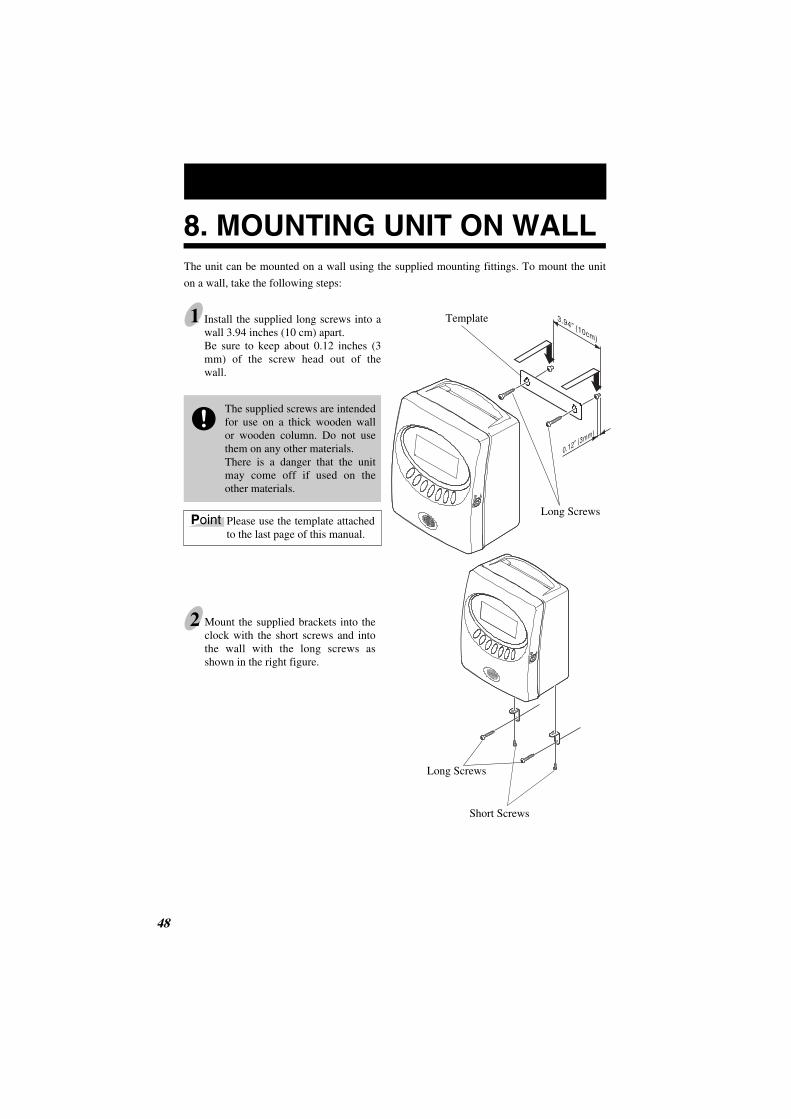
The unit can be mounted on a wall using the supplied mounting fittings. To mount the unit
on a wall, take the following steps:
The supplied screws are intended for use on a thick wooden wall or wooden column. Do not use them on any other materials.There is a danger that the unit may come off if used on the other materials.
Install the supplied long screws into a wall 3.94 inches (10 cm) apart.Be sure to keep about 0.12 inches (3 mm) of the screw head out of the wall.
Mount the supplied brackets into the clock with the short screws and into the wall with the long screws as shown in the right figure.
1
2
48 2
Please use the template attached to the last page of this manual.
8. MOUNTING UNIT ON WALL
Point
Template
Long Screws
Long Screws
Short Screws

9. INSTALLING THE OPTIONAL BATTERY BACK-UPThis option allows for printing without AC power.
14 49
1 Remove the cover of the battery compartment on the back of the unit by pushing the knob and then pull it toward you.
2 Position the battery as shown in the figure on the left.
3 Connect the connector. Tuck away the connector cord into the open space in the compartment.
4 Replace the cover into the slot as shown on the left. At that time make sure to fit the tabs at the bottom of the cover.
Knob
Tabs
The connector cord should be on the right side.
Make sure the cord is not caught when closing the Cover.
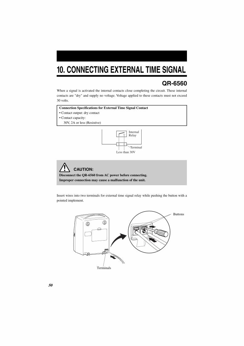
10. CONNECTING EXTERNAL TIME SIGNAL
When a signal is activated the internal contacts close completing the circuit. These internal
contacts are "dry" and supply no voltage. Voltage applied to these contacts must not exceed
30 volts.
Connection Specifications for External Time Signal Contact• Contact output: dry contact
• Contact capacity:
30V, 2A or less (Resistive)
Disconnect the QR-6560 from AC power before connecting.Improper connection may cause a malfunction of the unit.
50 2
Insert wires into two terminals for external time signal relay while pushing the button with a
pointed implement.
QR-6560
InternalRelay
Terminal
Less than 30V
CAUTION:
Terminals
Buttons

Anschluss-Schema für Externes Signal
Sofern ein Signal aktiviert wird, schliesst der Relais-Kontakt. Hierbei handelt es sich um
einen spannungsfreien Kontakt. Die zugeführte Spannung darf 30 Volt nicht uebersteigen.
Anschluss-Spezifikation fuer den Signal-Relaiskontakt Kontakt-Ausgang: Spannungsfrei
Kontakt-Last: 30 V, 2A max. (Ohmsche Last)
14 51
QR-6560
Internes Relais
Terminal
bis 30VAC max.
Den Eingangs-Spannungsstecker ziehen bevor Arbeiten am Relaisanschluss erfolgen. Fehlerhafter Anschluss kann zu Defekten an der QR-6560 führen.
Gemaess Abbildung den oberen Teil der Klemme mit einem Schraubenzieher drücken.Fuehre die Draehte einzeln ein.
Vorsicht:

11. TROUBLESHOOTINGError No. appears
Contact the store from whom you bought the unit.
Correctly insert the time card.
Insert a correct type of card.
Make sure that another time card is not jamming in the time recorder. Try to insert the time card again.
Contact the store from whom you bought the unit.
Make sure that another time card is not jamming in the time recorder and the ribbon cassette is correctly inserted in place.After making sure of the above, close the cover.
In case the card is completely stuck in the unit and does not come out, open the front case and remove a ribbon cassette first. Then, slide the card downwards and take it off from the button of the unit.Also check whether the correct card type is selected.
Make sure that another time card is not jamming in the time recorder and the ribbon cassette is correctly inserted in place.After making sure of the above, close the cover.
Input the correct password you set. (4-digit numbers)
Correctly set the daylight saving time.
Check the setting contents and input the correct figures.
Check the barcode area whether it is smudged or damaged.
Check whether the time was turned back or not. Also check whether the card was inserted within 1 minute after the last punch.
Check whether the day's 6th column was already used.Also check whether you can print if you change a time card or the day changes.
CPU error.
The remaining life of lithium battery for memory back-up is short.
The front and back of the time card inserted is wrong.
Inserted time card was wrong type.
The card is not pulled in properly.
RAM error.
Clock will not work.
Card sensor error.
Printing cannot be performed.The printer motor or sensor is not normal.
Inserted time card was wrong type.The card is stuck in the time recorder.
Printing cannot be performed.The printer motor is not normal.
Password error.
The start date and the end date of the daylight saving time are the same date.
Input the wrong figures.
Can’t use the time card.(QR-6560)
Punch error (punch time error).(QR-6560)
Punch error (punch logic error).(QR-6560)
E-00
E-01
E-03
E-04
E-05
E-10E-12E-15E-30
E-35
E-38
E-40
E-41
E-49
E-50
E-51
E-52
No. Error contents Action
*If the error number is still displayed, contact the store from whom you bought the unit.
252

•The unit does not operate.Check whether the power cord is properly in an AC outlet.
•The unit does not print.Check whether the ribbon is installed in place.
•Print is not located in the right place.Check whether the setting of the pay period ending date is set correctly.
Check whether the day advance time is set correctly.
Make sure that no part of the time card is folded, and that the time card is inserted
straightinto the unit.
If improper printing still remains after checking above points, contact the store from
whom you bought the unit.
• When the flat cable connected to the print head comes off, please set the cable as shown in
the following figure.
00 53
Other failures
Flat Cable
Holder
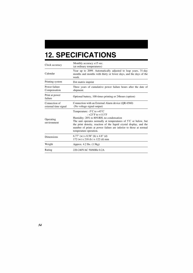
12. SPECIFICATIONS
54 2
Clock accuracy
Calendar
Printing system
Dimensions
Weight
Power failureCompensation
Print at powerfailure
Operating environment
Connection ofexternal time signal
Year up to 2099. Automatically adjusted to leap years, 31-day months and months with thirty or fewer days, and the days of the week.
Dot matrix imprint
Three years of cumulative power failure hours after the date of shipment.
Monthly accuracy ±15 sec.(at ordinary temperatures)
Optional battery, 100-times printing or 24hours (option)
Temperature: -5˚C to +45˚C : +23˚F to +113˚FHumidity: 20% to 80%RH, no condensationThe unit operates normally at temperatures of 5˚C or below, but the print density, reaction of the liquid crystal display, and the number of prints at power failure are inferior to those at normal temperature operation.
6.77" (w) x 8.58" (h) x 4.8" (d) 172 (w) x 218 (h ) x 122 (d) mm
Approx. 4.2 lbs. (1.9kg)
Rating 220-240VAC 50/60Hz 0.2A
Connection with an External Alarm device (QR-6560) (No voltage signal output)

Spezifikation
14 55
Uhr-Genauigkeit
Kalender
Drucksystem
Gewicht
Datenerhalt bei Spannungsfehler
Externes Signal
Funktionsumgebungs-Bedingungen
Nonstromversorgung(Option)
bis zum Jahr 2099, automatische Erkennung der Monatslaenge, Monatstage und Schaltjahr
Nadeldrucker
3 Jahre nach Spannungsausfall
Monatliche Abweichung ± 15 sec. (normale Umgebungstemperatur)
Temperatur: -5˚C bis +45˚C : +23˚F bis +113˚F20% bis 80% rel. Luftfeuchte, nicht kondensierend Das Gerät funktioniert auch unter +5˚C jedoch kann die Druckintensität und die Reaktionsstärke des LCD geringer sein, ebenso die Menge der Druckzyklen bei Betrieb mit optionaler Batterie.
ca. 1,9 kg
Masse 172 (B) x 218 (H) x 122 (T) mm
Spannungsversorgung 220-240VAC 0,2A 50/60Hz
Gangreserve für ca. 24 Std. oder 100 Registrierungen.
Anschluss eines externen Signalgebers (QR-6560)(Kontakt-Ausgang: Spannungsfrei)

Front Side Back Side
56 55
Unit: mm
13.TIME CARD SPECIFICATIONS
Monthly, both sides, with barcode(1) V / VN Card
86
7R2
9623
6
184
SignatureFrom: VN
DEPT.
NO. NAME
7C8
9623
6
001
Signature
DEPT.
NO. NAME
Sam
ple

Recommended Paper Thickness : 0.45 ± 0.05mm
Monthly, both sides(2) S Card
Front Side Back Side
56 57
NO.
DEPT. PAY PERIOD ENDING
NAME
REGULAR TIME OVERTIMEIN OUT IN OUT
1
Signature
NO.
DEPT. PAY PERIOD ENDING
NAME
REGULAR TIME OVERTIMEIN OUT IN OUT
2
Signature
9029
6
86
S
712R2C8
9623
6
712C8 R2
Unit: mm
184
Note

58 57
Unit: mm
Weekly, one side(3) Weekly Card
Bi-weekly, one side(4) Bi-Weekly Card
712R8
8435
6
7
86 86
12R8
4235
6
184
184
Recommended Paper Thickness : 0.45 ± 0.05mmNote

Front Side Back Side
58 59
Unit: mm
27
9623
6
7
86
7 12 7 71227 R3 R3
9623
62 2
184
Monthly, both sides(5) Other A Card
Recommended Paper Thickness : 0.45 ± 0.05mmNote

Front Side Back Side
60 59
Unit: mm
9623
686
R3 R3
9623
6
184
Monthly, both sides(6) Other B Card
Recommended Paper Thickness : 0.45 ± 0.05mmNote
712 712
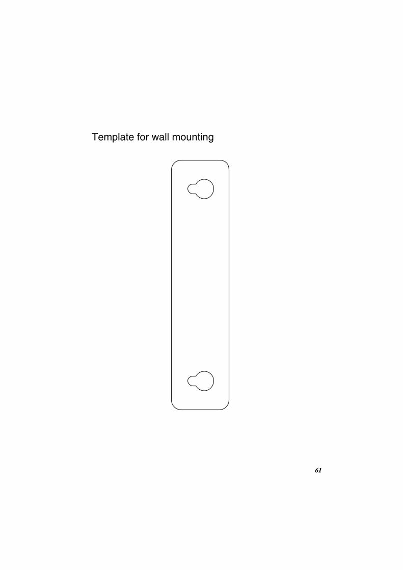
Template for wall mounting
61


Q0310-61201
ALL RIGHTS RESERVED © 2006


![Quick Response [QR] Code Reader6d2bab7c-4b9b-4c91-ad87-4410a610… · Quick Response [QR] Code Reader Halten Sie Ihren QR -Code-Reader bereit. Digitalisierung der Lehre Prof. Dr.](https://static.fdokument.com/doc/165x107/5f070f767e708231d41b1a7f/quick-response-qr-code-reader-6d2bab7c-4b9b-4c91-ad87-4410a610-quick-response.jpg)