Radiation testing on opto-electronic devices at SCK·CENRadiation testing on opto-electronic devices...
21
Radiation testing on opto-electronic devices at SCK·CEN 4th RD50 Workshop CERN, Genève - CH, 5-7 May 2004 Francis Berghmans Benoît Brichard, Alberto Fernandez Fernandez, Ivan Genchev, Andrei Goussarov, Marco Van Uffelen
Transcript of Radiation testing on opto-electronic devices at SCK·CENRadiation testing on opto-electronic devices...

Radiation testing on opto-electronic devices at SCK·CEN
4th RD50 WorkshopCERN, Genève - CH, 5-7 May 2004
Francis Berghmans
Benoît Brichard, Alberto Fernandez Fernandez, Ivan Genchev, Andrei Goussarov, Marco Van Uffelen

• Short presentation of SCK·CEN• Irradiation facilities• Some typical results on opto-
electronic devices• Future work

SCK•CEN
360 ha
Laboratories :Boeretang 200B-2400 MolBelgium
Registered Office :Av. Herrmann Debroux 40-42B-1160 BrusselsBelgium
Studiecentrum voor KernenergieCentre d’étude de L’Energie Nucléaire

SCK•CEN is a Research Institute
• Institute of Public UtilityMinistry of Economic Affairs
Secretary of State for Energy• 600 Employees
200 scientists• Annual Turnover 74•106 €
50 % Governmental subsidy -50 % Contracts• Core activities
Nuclear Safety and Radiation ProtectionIndustrial Applications of RadiationBack-end of the Nuclear Fuel CycleNon-energetic applications of nuclear energy
increasingly relevant to society – medicineSustained development and non-technical aspects
social and economical factors, ethics, liability

Our main R&D environment is ITER as supported by the
European Fusion Programme
• Environmental constraints
100 MGy (10 Grad)10 kGy·h-1 (1 Mrad·h-1)Occasional neutrons150 °C
• Instrumentation systems
CommunicationRemote-handling & sensorsFusion plasma diagnostics

We’ve been experimenting on a broad range of
devices/materials/technologies
• Laser diodes (AlGaAs VCSELs)• Photodiodes (Si, InGaAs)• A wealth of optical fibres
COTS and custom• Fibre Bragg Gratings• WDM Couplers• Liquid crystals• Fibre sensors• Electronics• Motors• Polymers• Cables (polymers, mineral insulated, …)• Connectors & feedthroughs• …

We exploit SCK·CEN’s irradiation infrastructure
Brigitte(60Co - fuel)
RITA(60Co)
Geuse II(fuel)
LNC(60Co)
Dose-ratemax.
Dose-ratemin.
Vol. (mm2)
Vol. Temp.
VUBCyclotron
1.4 krad•s-1
140 rad•s-1
300 rad•s-1
30 mrad•s-1 2 rad•s-1
15 rad•s-1 140 mrad•s-1
900 x 220900x80
600 x 380 400 x 380
50 - 200 °C RT - 100 °C RT RT stabilised
BR1
BR2
Hot cell
0.3 mrad•s-1

CERN irradiates opto-electronics for CMS in RITA

Vacuum System Module for RITA and GEUSE II is designed
• Vacuum: 10-5 mbar• Height: 600 mm• Diameter: 200 mm• Temperature: 120°C• Organic material
mass up to 1 kg
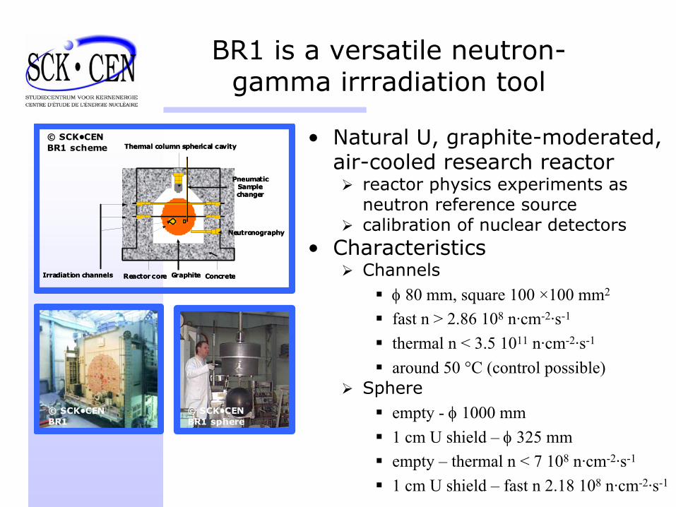
BR1 is a versatile neutron-gamma irrradiation tool
Reactor core Graphite Concrete
PneumaticSamplechanger
Neutronography
Irradiation channels
Thermal column spherical cavity
Reactor core Graphite Concrete
PneumaticSamplechanger
Neutronography
Irradiation channels
Thermal column spherical cavity
© SCK•CENBR1
© SCK•CENBR1 sphere
© SCK•CENBR1 scheme
• Natural U, graphite-moderated, air-cooled research reactor
reactor physics experiments as neutron reference sourcecalibration of nuclear detectors
• CharacteristicsChannels
φ 80 mm, square 100 ×100 mm2
fast n > 2.86 108 n·cm-2·s-1
thermal n < 3.5 1011 n·cm-2·s-1
around 50 °C (control possible)Sphere
empty - φ 1000 mm1 cm U shield – φ 325 mmempty – thermal n < 7 108 n·cm-2·s-1
1 cm U shield – fast n 2.18 108 n·cm-2·s-1

BR2 is a high neutron flux material testing reactor
© SCK•CENBR2
© SCK•CENBR2 configuration
© SCK•CENBR2 scheme
• PWR type reactor (flux up to 1015 n·cm-2·s-1)
test of fuels and materialsproduction of radioisotopessilicon doping for electronics industry
• CharacteristicsCentral channels
φ 84 mmfast n – 2 1014 n·cm-2·s-1
thermal n – 4 1014 n·cm-2·s-1
(5 W·g-1 Al)Peripheral
φ 200 mmfast n – 3.5 1014 n·cm-2·s-1
thermal n – 1 1014 n·cm-2·s-1
(4 W·g-1 Al)

Aging, lifetime testing and temperature cycling studied in
CLARA (2 m³)

We can cover most radiation effects application fields

Gamma rays and Neutrons have different effects on VCSEL P-I curve
• Gamma IrradiationNo threshold current shiftExternal efficiency decrease
• Neutron IrradiationThreshold current shiftExternal efficiency decrease
0 2 4 6 8 10 12 14 16 180.0
0.2
0.4
0.6
0.8
1.0
Out
put P
ower
(mW
)
Forward Current If (mA)
Unirradiated 0.5 MGy 1.0 MGy 2.0 MGy 4.0 MGy 10 MGy
0 2 4 6 8 10 12 14 16 180.0
0.1
0.2
0.3
0.4
0.5
0.6
Out
put P
ower
(mW
)
Forward Current If (A)
Unirradiated 1.02E14 n/cm² 5.20E14 n/cm² 9.45E14 n/cm² 1.37E15 n/cm² 1.79E15 n/cm² 2.22E15 n/cm² 2.64E15 n/cm² 3.07E15 n/cm² 3.49E15 n/cm²
F. Berghmans et al., "Design and Characterization of a Radiation Tolerant Optical Transmitter using Discrete COTS Bipolar Transistors and VCSELs", IEEE Transactions on Nuclear Science 49, pp. 1414-1420, 2002
Pre-irradiation with gamma accelerates degradation

COTS p-i-n photodiodes were monitored in-situ under radiation
• First 60Co gamma experiment6 Si-PD2 kGy/h (10% accur.), 2 MGy, 60°C ± 1.5°C
• Mixed neutron/gamma experimentpre-irradiated Si-PD (2 MGy)7·1015n/cm2, 20 kGy (background), 60°C ± 1.5°C
• Second 60Co gamma experiment8 Si-PD & 8 InGaAs-PD15 kGy/h (10% accur.), 10 MGy, 60°C ± 1.5°C

A typical result for a Siphotodiode after 2 MGy
Response PD 1 @ 850 nm
y = 0.4595xR2 = 0.9991
y = 0.4127xR2 = 0.9981
0E+00
1E-06
2E-06
3E-06
4E-06
5E-06
6E-06
7E-06
8E-06
9E-06
0E+00 5E-06 1E-05 2E-05 2E-05 3E-05
Incident power [W]
Phot
ocur
rent
[A]
beginendResponse PD1 (begin)Response PD1 (end)
4-5% after 2 MGy
M. Van Uffelen et al., "Reliability study of photodiodes for their potential use in future fusion reactor environments", SPIE Proceedings 5465, 2004, to be published

Neutron displacement damage is an issue
Response PD1 in BR1 @ 850 nm
y = 0.4489x + 2E-08R2 = 0.9988
y = 0.3649x + 9E-06R2 = 0.9983
-2E-06
0E+00
2E-06
4E-06
6E-06
8E-06
1E-05
1E-05
1E-05
0.0E+00 4.0E-06 8.0E-06 1.2E-05 1.6E-05
Incident power [W]
Phot
curr
ent [
A]
beginend
~ 10%
x 103
Total dose : Dγ = 20 kGyFluence : nth = 7·1015n/cm2
M. Van Uffelen et al., "Reliability study of photodiodes for their potential use in future fusion reactor environments", SPIE Proceedings 5465, 2004, to be published

InGaAs photodiodes show different dark current curves
after irradiation
Dark current PD 1 (after 10 MGy)
0E+00
1E-06
2E-06
3E-06
4E-06
5E-06
6E-06
7E-06
8E-06
0 5 10 15 20 25Reverse voltage [V]
Cur
rent
[A]
70°C60°C_begin60°C_end50°C40°C
Dark current PD 1 (before irradiation)
0.0E+00
5.0E-10
1.0E-09
1.5E-09
2.0E-09
2.5E-09
3.0E-09
0 5 10 15 20 25Reverse voltage [V]
Cur
rent
[A]
70°C
60°C
50°C
40°C
M. Van Uffelen et al., "Reliability study of photodiodes for their potential use in future fusion reactor environments", SPIE Proceedings 5465, 2004, to be published
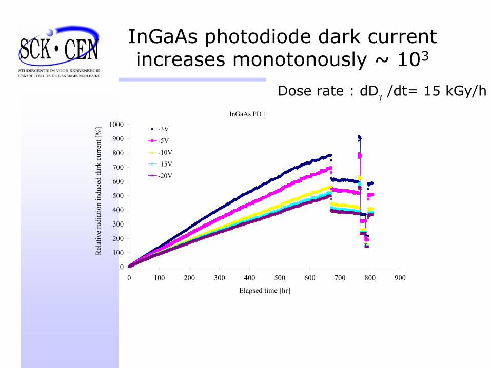
InGaAs photodiode dark current increases monotonously ~ 103
InGaAs PD 1
0
100
200
300
400
500
600
700
800
900
1000
0 100 200 300 400 500 600 700 800 900
Elapsed time [hr]
Rel
ativ
e ra
diat
ion
indu
ced
dark
cur
rent
[%] -3V
-5V
-10V
-15V
-20V
Dose rate : dDγ /dt= 15 kGy/h

Packaging is an issue
Before irradiation After irradiation

Future work is needed and could benefit from interaction with RD50
• Effects are generally understood but phenomenologically treated
No thorough theoretical investigation on material radiation effects RD50Material effects, device structure effects and device performance need to be linkedModelling is essential for reliability assessment RD50
• Further experimental workGain statistical significanceQualification is essential but expensive and time consuming
• Our irradiation facilities are availableand can be adapted to your specific needs RD50


![Testing Testing: Putting Translation Usability to the Test · Juho Suokas & Kaisa Pukarinen & Stuart von Wolff & Kaisa Koskinen trans-kom 8 [2] (2015): 499-519 Testing Testing Seite](https://static.fdokument.com/doc/165x107/5c6634e409d3f2c14e8bbfef/testing-testing-putting-translation-usability-to-the-juho-suokas-kaisa-pukarinen.jpg)