Raytheon Anschutz DISTRIBUTION UNIT COMPACT Type 138-126
32
Raytheon Anschütz GmbH Postfach 1166 D -- 24100Kiel Germany Tel +49--4 31--30 19--0 Fax +49--4 31--30 19--501 Email [email protected] www.raytheon--anschuetz.de 3815.DOC010002 Edition: Sept. 1, 2005 Revision: Nov. 28, 2005 Revision: Feb. 17, 2006 Revision: Feb. 13, 2008 DISTRIBUTION UNIT COMPACT Type 138--126 1 Description 2 Installation
description
Description and installation of Raytheon Anschutz distribution unit type 138-126Edition: Sept. 1, 2005Revision: Nov. 28, 2005Revision: Feb. 17, 2006Revision: Feb. 13, 2008
Transcript of Raytheon Anschutz DISTRIBUTION UNIT COMPACT Type 138-126
Raytheon Anschütz GmbHPostfach 1166D -- 24100 KielGermanyTel +49--4 31--30 19--0Fax +49--4 31--30 19--501Email [email protected]
3815.DOC010002 Edition: Sept. 1, 2005Revision: Nov. 28, 2005Revision: Feb. 17, 2006Revision: Feb. 13, 2008
DISTRIBUTION UNIT COMPACT
Type 138--126
1 Description2 Installation

Weitergabe sowie Vervielfältigung dieser Unterlage, Verwertung undMitteilung ihres Inhaltes nicht gestattet, soweit nicht ausdrücklichzugestanden. Zuwiderhandlungen verpflichten zu Schadenersatz.
Copying of this document, and giving it to others and the use orcommunication of the contents thereof, are forbidden without expressauthority. Offenders are liable to the payment of damages.
Toute communication ou reproduction de ce document, touteexploitation ou communication de son contenu sont interdites, saufautorisation expresse. Tout manquement à cette règle est illicite etexpose son auteur au versement de dommages et intérêts.
Sin nuestra expresa autorización, queda terminantemente prohibida lareproducción total o parcial de este documento, así como su usoindebido y/o su exhibición o comunicación a terceros. De los infractoresse exigirá el correspondiente resarcimiento de daños y perjuicios.
Distribution Unit compact
138--126DISTRIBUTION
UNIT
I 3815.DOC010002Edition: Sept. 1, 2005
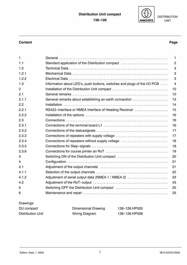
Content Page
1 General 1. . . . . . . . . . . . . . . . . . . . . . . . . . . . . . . . . . . . . . . . . . . . . . . . . . . . . . . . . . . . . . .1.1 Standard application of the Distribution compact 2. . . . . . . . . . . . . . . . . . . . . . . . . . .1.2 Technical Data 3. . . . . . . . . . . . . . . . . . . . . . . . . . . . . . . . . . . . . . . . . . . . . . . . . . . . . . . . .1.2.1 Mechanical Data 3. . . . . . . . . . . . . . . . . . . . . . . . . . . . . . . . . . . . . . . . . . . . . . . . . . . . . . .1.2.2 Electrical Data 3. . . . . . . . . . . . . . . . . . . . . . . . . . . . . . . . . . . . . . . . . . . . . . . . . . . . . . . . .1.3 Information about LED‘s, push buttons, switches and plugs of the I/O PCB 4. . . .2 Installation of the Distribution Unit compact 10. . . . . . . . . . . . . . . . . . . . . . . . . . . . . . . .2.1 General remarks 10. . . . . . . . . . . . . . . . . . . . . . . . . . . . . . . . . . . . . . . . . . . . . . . . . . . . . . .2.1.1 General remarks about establishing an earth connection 13. . . . . . . . . . . . . . . . . . . .2.2 Installation 14. . . . . . . . . . . . . . . . . . . . . . . . . . . . . . . . . . . . . . . . . . . . . . . . . . . . . . . . . . . .2.2.1 RS422--Interface or NMEA Interface of Heading Receiver 15. . . . . . . . . . . . . . . . . . .2.2.2 Installation of the options 16. . . . . . . . . . . . . . . . . . . . . . . . . . . . . . . . . . . . . . . . . . . . . . . .2.3 Connections 16. . . . . . . . . . . . . . . . . . . . . . . . . . . . . . . . . . . . . . . . . . . . . . . . . . . . . . . . . . .2.3.1 Connections of the terminal board L1 16. . . . . . . . . . . . . . . . . . . . . . . . . . . . . . . . . . . . .2.3.2 Connections of the statussignals 17. . . . . . . . . . . . . . . . . . . . . . . . . . . . . . . . . . . . . . . . .2.3.3 Connections of repeaters with supply voltage 17. . . . . . . . . . . . . . . . . . . . . . . . . . . . . .2.3.4 Connections of repeaters without supply voltage 18. . . . . . . . . . . . . . . . . . . . . . . . . . .2.3.5 Connections for Step--signals 18. . . . . . . . . . . . . . . . . . . . . . . . . . . . . . . . . . . . . . . . . . . .2.3.6 Connections for course printer an RoT 19. . . . . . . . . . . . . . . . . . . . . . . . . . . . . . . . . . . .3 Switching ON of the Distribution Unit compact 20. . . . . . . . . . . . . . . . . . . . . . . . . . . . .4 Configuration 21. . . . . . . . . . . . . . . . . . . . . . . . . . . . . . . . . . . . . . . . . . . . . . . . . . . . . . . . . .4.1 Adjustment of the output channels 21. . . . . . . . . . . . . . . . . . . . . . . . . . . . . . . . . . . . . . .4.1.1 Selection of the output channels 22. . . . . . . . . . . . . . . . . . . . . . . . . . . . . . . . . . . . . . . . .4.1.2 Adjustment of serial output data (NMEA 1 / NMEA 2) 23. . . . . . . . . . . . . . . . . . . . . . .4.2 Adjustment of the RoT--output 43. . . . . . . . . . . . . . . . . . . . . . . . . . . . . . . . . . . . . . . . . . .5 Switching OFF the Distribution Unit compact 25. . . . . . . . . . . . . . . . . . . . . . . . . . . . . .6 Maintenance and repair 25. . . . . . . . . . . . . . . . . . . . . . . . . . . . . . . . . . . . . . . . . . . . . . . . .
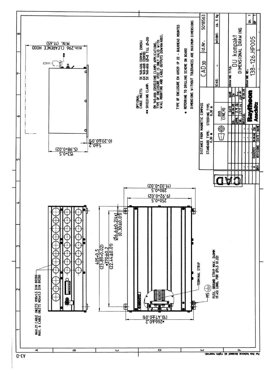
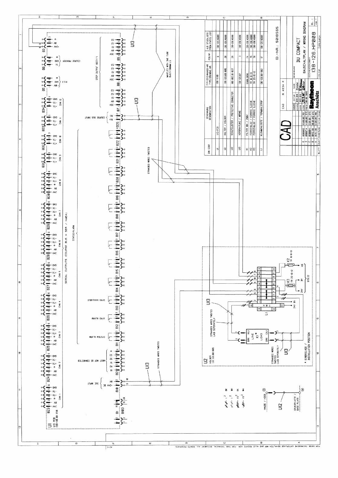
Drawings:DU compact Dimensional Drawing 138--126.HP005Distribution Unit Wiring Diagram 138--126.HP008
Distribution Unit compact
138--126
II Edition: Sept. 1, 20053815.DOC010002
Safety regulations
Caution:Installation, maintenance and repair work must becarried out only by properly trained and qualified staffwith a good knowledge of national equipment safetyregulations.
Distribution Unit compact
138--126DISTRIBUTION
UNIT
1 3815.DOC010002Edition: Feb. 17, 2006
1 General
The Distribution Unit compact 138--126 consist of an aluminium casting in which aprinted circuit board is integrated:-- I/O PCB.
At the bottom of the casting there are 27 cable inlets for connecting repeaters, gyros andother heading receivers and sensors.
The task of this Distribution Unit compact is:
-- System monitoring by alarm-- and status messages.-- Distribution of corrected heading information to all connected heading receivers.-- Power supply of all connected heading receivers (8 heading receivers and
3 step--outputs supplied with power and of the connected heading sensor (compass).
There are operating procedures during the operation of the Distribution Unit compact.Only the setting to work--procedure needs some settings performed by DIP--Switches atthe I/O PCB.
Options are:
“AC/DC--Converter” to generate the supply voltage for the Distribution Unit compact.
Distribution Unit compact
138--126
23815.DOC010002 Edition: Feb. 17, 2006
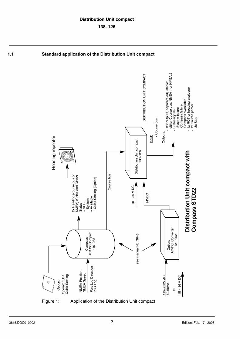
1.1 Standard application of the Distribution Unit compact
24VDC
18--36
VDC
AC/DC
Converter
121--062
Option:
115--230VAC
50/60H
z
Com
pass
STD22
Com
pact
110--233
orNMEAPosition
NMEASpeed
PulsLogDirection
PulsLog
2xHeading
(coursebusor
NMEA)(CHn1
andCHn2)
Status
--SEC
--System
--Available
--Quick
Settling
(Option)
Coursebus DistributionUnitcom
pact
138--126
�
OperatorUnit
Quick
Settling
Option:
DistributionUnitcompactwith
CompassSTD22
Heading
repeater
18--36
VDC
DISTRIBUTIONUNITCOMPA
CT
Input: --Coursebus
Outputs: --12xoutputs,separateadjustable:
eitherCoursebus,NMEA1orNMEA2
--Statussignals:
Systemfailure
Com
pass
failure
Com
pass
avaailable
--1x
ROTorheadinganalogue
--1x
Courseprinter
--3x
Step
seemanualN
o.:3646
Figure 1: Application of the Distribution Unit compact
Distribution Unit compact
138--126DISTRIBUTION
UNIT
3 3815.DOC010002Edition: Feb. 17, 2006
1.2 Technical Data
1.2.1 Mechanical Data
Dimensions, weight and internal protectionsee Dimensional Drawing “DU compact 138--126.HP005”
1.2.2 Electrical Data
Supply voltage: 18VDC.......36VDCPower consumption: 6W at 24V DC Supply voltage
(without connected receivers and compass)
Inputs:Course bus
Outputs:-- 12 outputs (electrical RS422), 8 channels with supply voltage for
heading receiverseach channel separate adjustable
heading serial (Course bus)NMEA1 (Heading and/or RoT, different transmission rates)NMEA2 (Heading and RoT, different transmission rates
-- RoT analog or heading analog (+/-- 10V)-- Course printer interface RS232C-- 3 STEP--Signals 1/6°/Step (with voltage supply 35V DC)-- Statussignals
System failureCompass failureCompass available
Distribution Unit compact
138--126
43815.DOC010002 Edition: Feb. 17, 2006
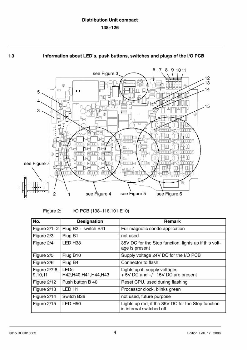
1.3 Information about LED‘s, push buttons, switches and plugs of the I/O PCB
see Figure 4 see Figure 5 see Figure 6
see Figure 3
12
3
4
5
6 7 8 9 1011
121314
15
see Figure 7
Figure 2: I/O PCB (138--118.101.E10)
No. Designation Remark
Figure 2/1+2 Plug B2 + switch B41 Für magnetic sonde application
Figure 2/3 Plug B1 not used
Figure 2/4 LED H38 35V DC for the Step function, lights up if this volt-age is present
Figure 2/5 Plug B10 Supply voltage 24V DC for the I/O PCB
Figure 2/6 Plug B4 Connector to flash
Figure 2/7,8,9,10,11
LEDsH42,H40,H41,H44,H43
Lights up if, supply voltages+ 5V DC and +/-- 15V DC are present
Figure 2/12 Push button B 40 Reset CPU, used during flashing
Figure 2/13 LED H1 Processor clock, blinks green
Figure 2/14 Switch B36 not used, future purpose
Figure 2/15 LED H50 Lights up red, if the 35V DC for the Step functionis internal switched off.
Distribution Unit compact
138--126DISTRIBUTION
UNIT
5 3815.DOC010002Edition: Sept. 1, 2005
1 2 3 4 5
B 39
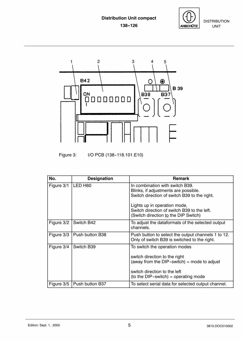
Figure 3: I/O PCB (138--118.101.E10)
No. Designation Remark
Figure 3/1 LED H60 In combination with switch B39.Blinks, if adjustments are possible.Switch direction of switch B39 to the right.
Lights up in operation mode,Switch direction of switch B39 to the left.(Switch direction to the DIP Switch)
Figure 3/2 Switch B42 To adjust the dataformats of the selected outputchannels.
Figure 3/3 Push button B38 Push button to select the output channels 1 to 12.Only of switch B39 is switched to the right.
Figure 3/4 Switch B39 To switch the operation modes
switch direction to the right(away from the DIP--switch) = mode to adjust
switch direction to the left(to the DIP--switch) = operating mode
Figure 3/5 Push button B37 To select serial data for selected output channel.
Distribution Unit compact
138--126
63815.DOC010002 Edition: Sept. 1, 2005
1 2 3 4 5 6
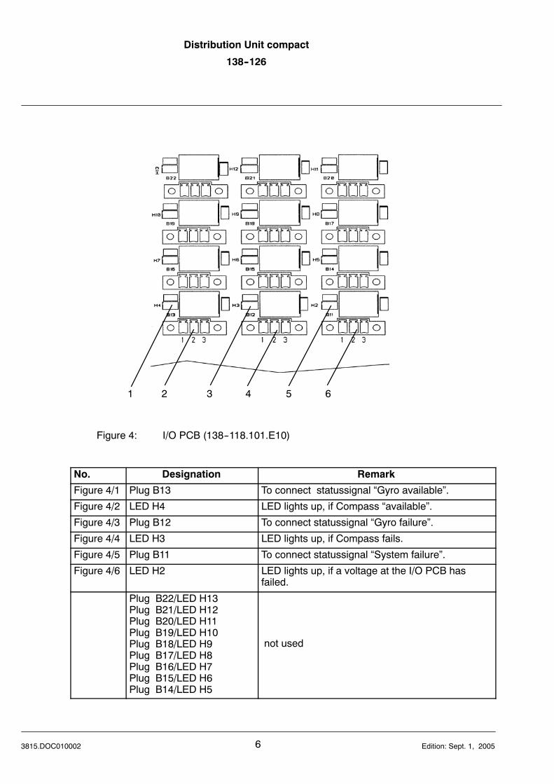
Figure 4: I/O PCB (138--118.101.E10)
No. Designation Remark
Figure 4/1 Plug B13 To connect statussignal “Gyro available”.
Figure 4/2 LED H4 LED lights up, if Compass “available”.
Figure 4/3 Plug B12 To connect statussignal “Gyro failure”.
Figure 4/4 LED H3 LED lights up, if Compass fails.
Figure 4/5 Plug B11 To connect statussignal “System failure”.
Figure 4/6 LED H2 LED lights up, if a voltage at the I/O PCB hasfailed.
Plug B22/LED H13Plug B21/LED H12Plug B20/LED H11Plug B19/LED H10Plug B18/LED H9Plug B17/LED H8Plug B16/LED H7Plug B15/LED H6Plug B14/LED H5
not used
Distribution Unit compact
138--126DISTRIBUTION
UNIT
7 3815.DOC010002Edition: Sept. 1, 2005
1
2
3
4
5
6
7
8 9 10
11
12
13
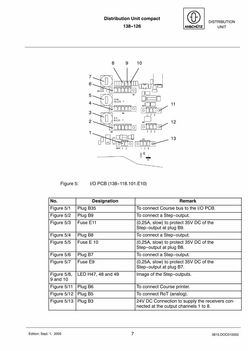
Figure 5: I/O PCB (138--118.101.E10)
No. Designation Remark
Figure 5/1 Plug B35 To connect Course bus to the I/O PCB.
Figure 5/2 Plug B9 To connect a Step--output.
Figure 5/3 Fuse E11 (0,25A, slow) to protect 35V DC of theStep--output at plug B9.
Figure 5/4 Plug B8 To connect a Step--output.
Figure 5/5 Fuse E 10 (0,25A, slow) to protect 35V DC of theStep--output at plug B8.
Figure 5/6 Plug B7 To connect a Step--output.
Figure 5/7 Fuse E9 (0,25A, slow) to protect 35V DC of theStep--output at plug B7.
Figure 5/8,9 and 10
LED H47, 48 and 49 Image of the Step--outputs.
Figure 5/11 Plug B6 To connect Course printer.
Figure 5/12 Plug B5 To connect RoT (analog).
Figure 5/13 Plug B3 24V DC Connection to supply the receivers con-nected at the output channels 1 to 8.
Distribution Unit compact
138--126
83815.DOC010002 Edition: Sept. 1, 2005
(Channel 5) 1
(Channel 6) 2
(Channel 7) 3
(Channel 8) 4 5 (Channel 4)
6 (Channel 3)
7 (Channel 2)
8 (Channel 1)
9101112(Channel 9)(Channel 10)(Channel 11)(Channel12)
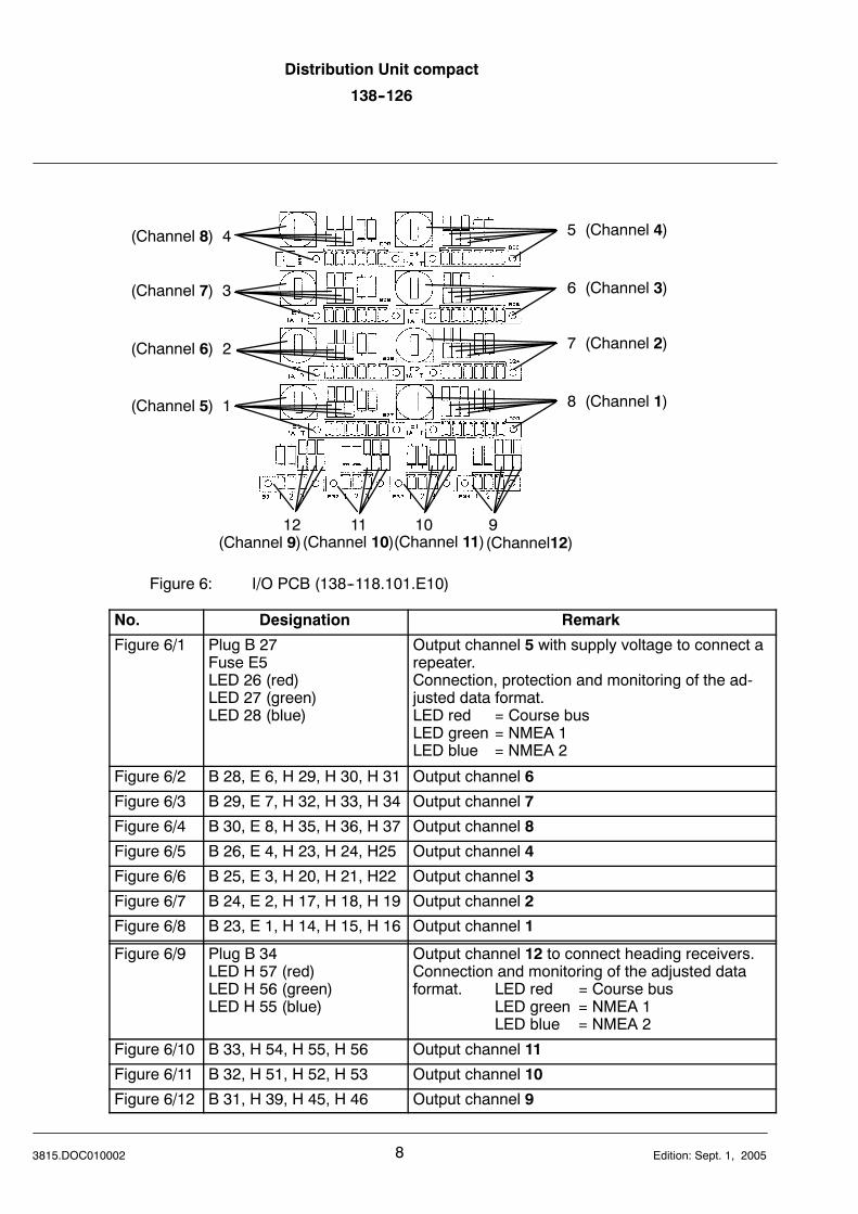
Figure 6: I/O PCB (138--118.101.E10)
No. Designation Remark
Figure 6/1 Plug B 27Fuse E5LED 26 (red)LED 27 (green)LED 28 (blue)
Output channel 5 with supply voltage to connect arepeater.Connection, protection and monitoring of the ad-justed data format.LED red = Course busLED green = NMEA 1LED blue = NMEA 2
Figure 6/2 B 28, E 6, H 29, H 30, H 31 Output channel 6
Figure 6/3 B 29, E 7, H 32, H 33, H 34 Output channel 7
Figure 6/4 B 30, E 8, H 35, H 36, H 37 Output channel 8
Figure 6/5 B 26, E 4, H 23, H 24, H25 Output channel 4
Figure 6/6 B 25, E 3, H 20, H 21, H22 Output channel 3
Figure 6/7 B 24, E 2, H 17, H 18, H 19 Output channel 2
Figure 6/8 B 23, E 1, H 14, H 15, H 16 Output channel 1
Figure 6/9 Plug B 34LED H 57 (red)LED H 56 (green)LED H 55 (blue)
Output channel 12 to connect heading receivers.Connection and monitoring of the adjusted dataformat. LED red = Course bus
LED green = NMEA 1LED blue = NMEA 2
Figure 6/10 B 33, H 54, H 55, H 56 Output channel 11
Figure 6/11 B 32, H 51, H 52, H 53 Output channel 10
Figure 6/12 B 31, H 39, H 45, H 46 Output channel 9
Distribution Unit compact
138--126DISTRIBUTION
UNIT
9 3815.DOC010002Edition: Sept. 1, 2005
1 2
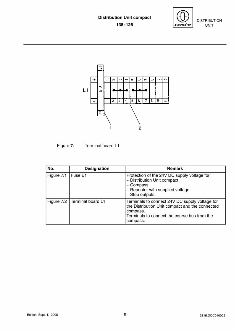
Figure 7: Terminal board L1
No. Designation Remark
Figure 7/1 Fuse E1 Protection of the 24V DC supply voltage for:-- Distribution Unit compact-- Compass-- Repeater with supplied voltage-- Step outputs
Figure 7/2 Terminal board L1 Terminals to connect 24V DC supply voltage forthe Distribution Unit compact and the connectedcompass.Terminals to connect the course bus from thecompass.
Distribution Unit compact
138--126
103815.DOC010002 Edition: Sept. 1, 2005
2 Installation of the Distribution Unit compact
2.1 General remarks
CautionWhen establishing cable connections ensure that thecables are disconnected from the power supply.It is essential to ensure that all cables are disconnectedfrom the power supply, if necessary measure the voltagebeforehand and/or disconnect the relevant distributor.
In order to ensure that the system operates correctly, it is essential that you follow theprocedures described below for establishing cable connections.For information to the respective cable diameter see Wiring diagram138--126.HP008.
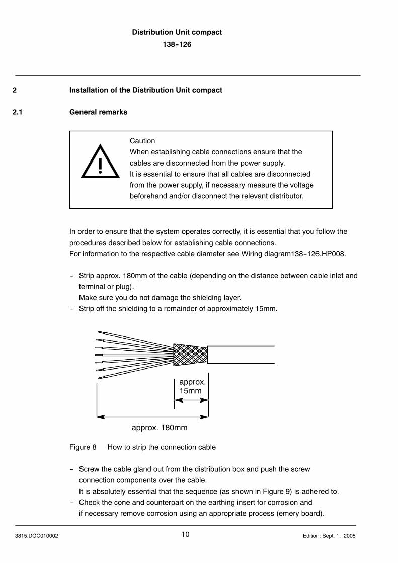
-- Strip approx. 180mm of the cable (depending on the distance between cable inlet andterminal or plug).Make sure you do not damage the shielding layer.
-- Strip off the shielding to a remainder of approximately 15mm.
approx. 180mm
approx.15mm
Figure 8 How to strip the connection cable
-- Screw the cable gland out from the distribution box and push the screwconnection components over the cable.It is absolutely essential that the sequence (as shown in Figure 9) is adhered to.
-- Check the cone and counterpart on the earthing insert for corrosion andif necessary remove corrosion using an appropriate process (emery board).
Distribution Unit compact
138--126DISTRIBUTION
UNIT
11 3815.DOC010002Edition: Sept. 1, 2005
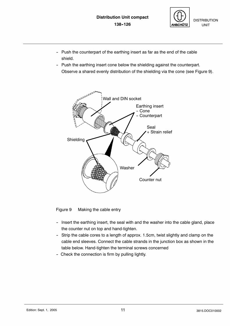
-- Push the counterpart of the earthing insert as far as the end of the cableshield.
-- Push the earthing insert cone below the shielding against the counterpart.
Observe a shared evenly distribution of the shielding via the cone (see Figure 9).
Wall and DIN socket
Shielding
Earthing insert-- Cone-- Counterpart
Seal+ Strain relief
Washer
Counter nut
Figure 9 Making the cable entry
-- Insert the earthing insert, the seal with and the washer into the cable gland, placethe counter nut on top and hand-tighten.
-- Strip the cable cores to a length of approx. 1.5cm, twist slightly and clamp on thecable end sleeves. Connect the cable strands in the junction box as shown in thetable below. Hand-tighten the terminal screws concerned
-- Check the connection is firm by pulling lightly.
Distribution Unit compact
138--126
123815.DOC010002 Edition: Sept. 1, 2005
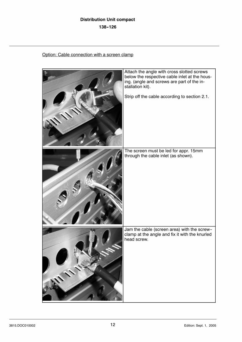
Option: Cable connection with a screen clamp
Attach the angle with cross slotted screwsbelow the respective cable inlet at the hous-ing. (angle and screws are part of the in-stallation kit).
Strip off the cable according to section 2.1.
The screen must be led for appr. 15mmthrough the cable inlet (as shown).
Jam the cable (screen area) with the screw--clamp at the angle and fix it with the knurledhead screw.
Distribution Unit compact
138--126DISTRIBUTION
UNIT
13 3815.DOC010002Edition: Sept. 1, 2005
2.1.1 General information about establishing an earth connection
In order to comply with the stringent EMC requirements, please abide by the informationgiven below regarding cable connections.Use the cable types specified.
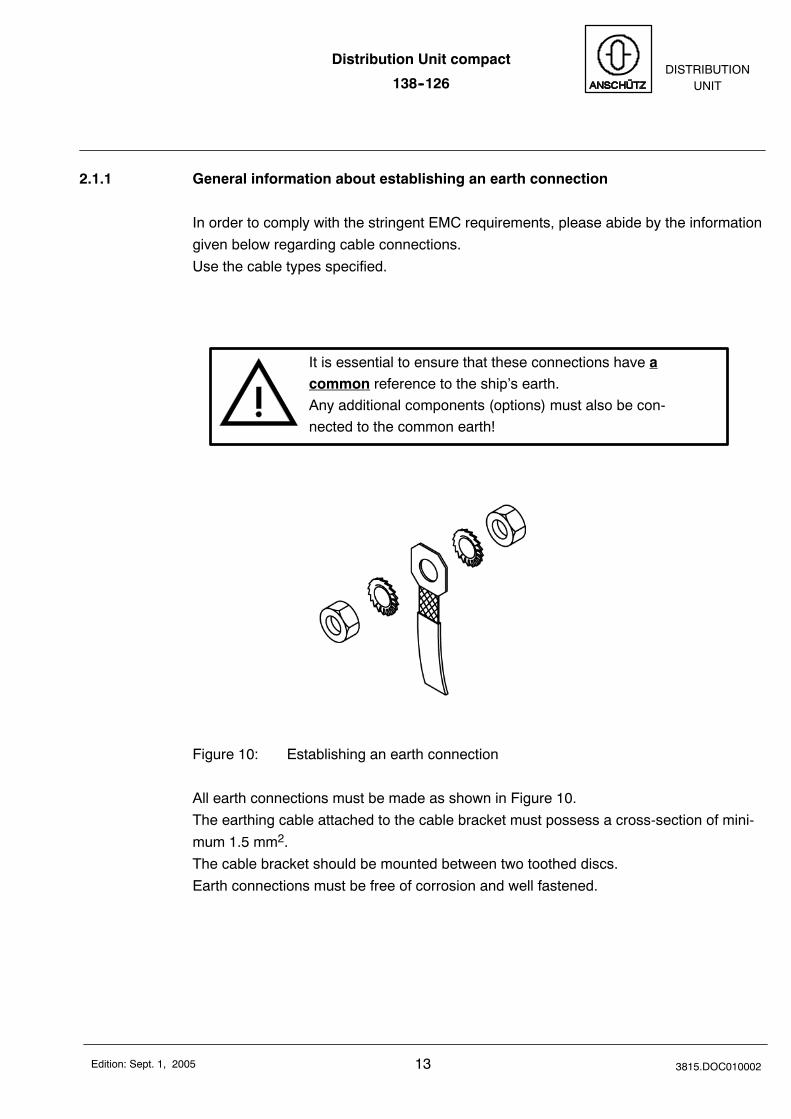
It is essential to ensure that these connections have acommon reference to the ship’s earth.Any additional components (options) must also be con-nected to the common earth!
Figure 10: Establishing an earth connection
All earth connections must be made as shown in Figure 10.The earthing cable attached to the cable bracket must possess a cross-section of mini-mum 1.5 mm2.The cable bracket should be mounted between two toothed discs.Earth connections must be free of corrosion and well fastened.
Distribution Unit compact
138--126
143815.DOC010002 Edition: Sept. 1, 2005
2.2 Installation
The distribution unit has to be mounted according to the dimensional drawing138--126.HP005.The front cover should be removable.Please note the comment depending the internal protection at the dimensional drawing.
Distribution Unit compact
138--126DISTRIBUTION
UNIT
15 3815.DOC010002Edition: Feb. 13, 2008
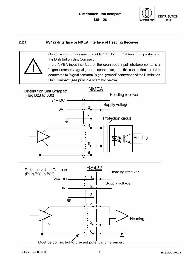
2.2.1 RS422--Interface or NMEA Interface of Heading Receiver
Conclusion for the connection of NON RAYTHEON Anschütz products tothe Distribution Unit Compact:If the NMEA input interface or the coursebus input interface contains a“signal common / signal ground” connection, then this connection has to beconnected to “signal common / signal ground” connection of theDistribitionUnit Compact (see principle scematic below).
NMEADistribution Unit Compact(Plug B23 to B30) Heading receiver
1
2
3
4
5
6
24V DC
0VSupply voltage
RS422
Heading
Heading receiver1
2
3
4
5
6
24V DC
0VSupply voltage
Heading
Must be connected to prevent potential differences.
Protection circuit
Distribution Unit Compact(Plug B23 to B30)
Distribution Unit compact
138--126
163815.DOC010002 Edition: Feb. 13, 2008
2.2.2 Installation of the options
For installation of the option “AC/DC--Converter”, see service manual of thecompass STD 22.
2.3 Connections
For additional information to the connectors, see Wiring diagram 138--126.HP008.
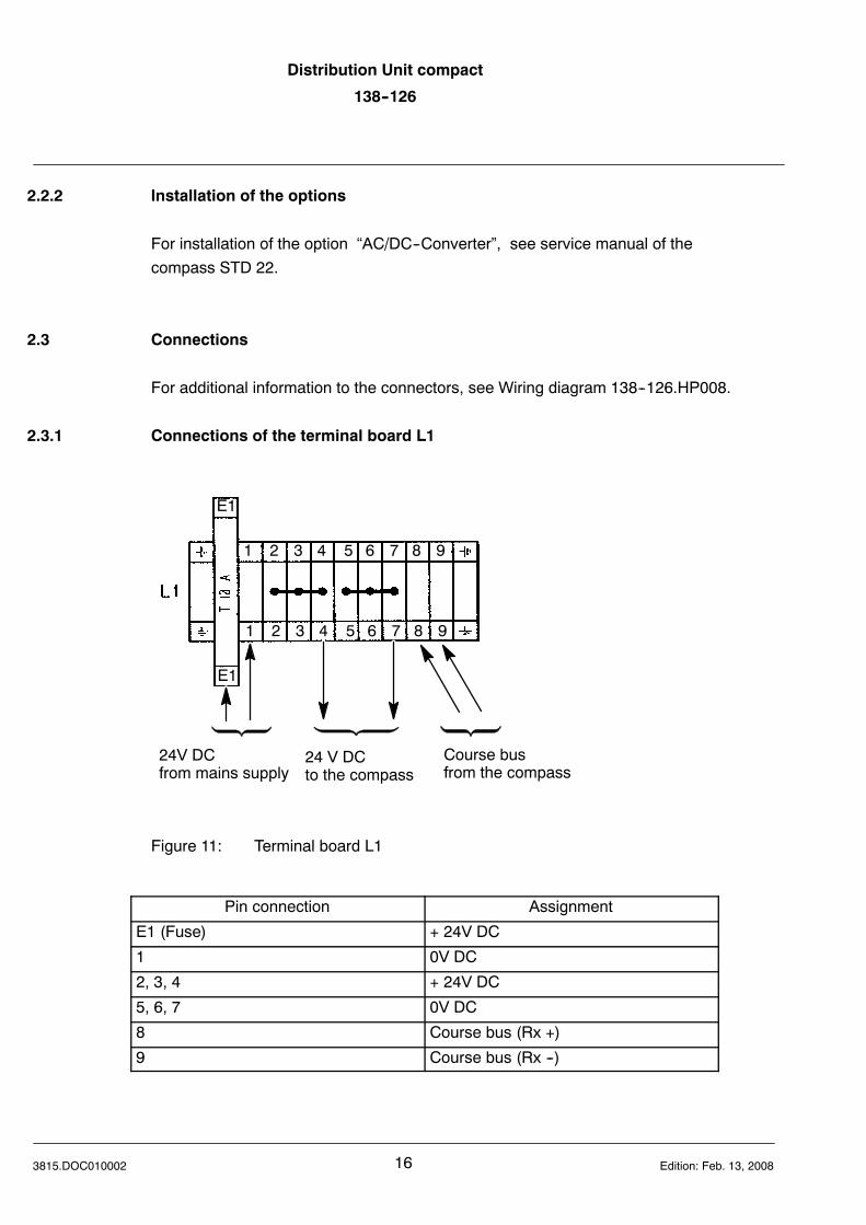
2.3.1 Connections of the terminal board L1
24V DCfrom mains supply
24 V DCto the compass
E1
E1
1 2 3 4 5 6 7 8 9
1 2 3 4 5 6 7 8 9
Course busfrom the compass
Figure 11: Terminal board L1
Pin connection Assignment
E1 (Fuse) + 24V DC
1 0V DC
2, 3, 4 + 24V DC
5, 6, 7 0V DC
8 Course bus (Rx +)
9 Course bus (Rx --)
Distribution Unit compact
138--126DISTRIBUTION
UNIT
17 3815.DOC010002Edition: Sept. 1, 2005
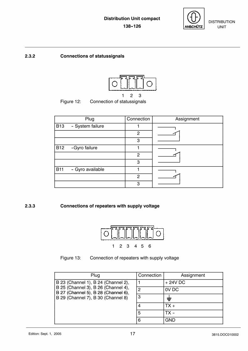
2.3.2 Connections of statussignals
1 2 3Figure 12: Connection of statussignals
Plug Connection Assignment
B13 -- System failure 1
2
3
B12 --Gyro failure 1
2
3
B11 -- Gyro available 1
2
3
2.3.3 Connections of repeaters with supply voltage
1 2 3 4 5 6
Figure 13: Connection of repeaters with supply voltage
Plug Connection Assignment
B 23 (Channel 1), B 24 (Channel 2),B 25 (Ch l 3) B 26 (Ch l 4)
1 + 24V DCB 25 (Channel 3), B 26 (Channel 4),B 27 (Channel 5), B 28 (Channel 6),
2 0V DCB 27 (Channel 5), B 28 (Channel 6),B 29 (Channel 7), B 30 (Channel 8) 3
4 TX +
5 TX --
6 GND
Distribution Unit compact
138--126
183815.DOC010002 Edition: Sept. 1, 2005
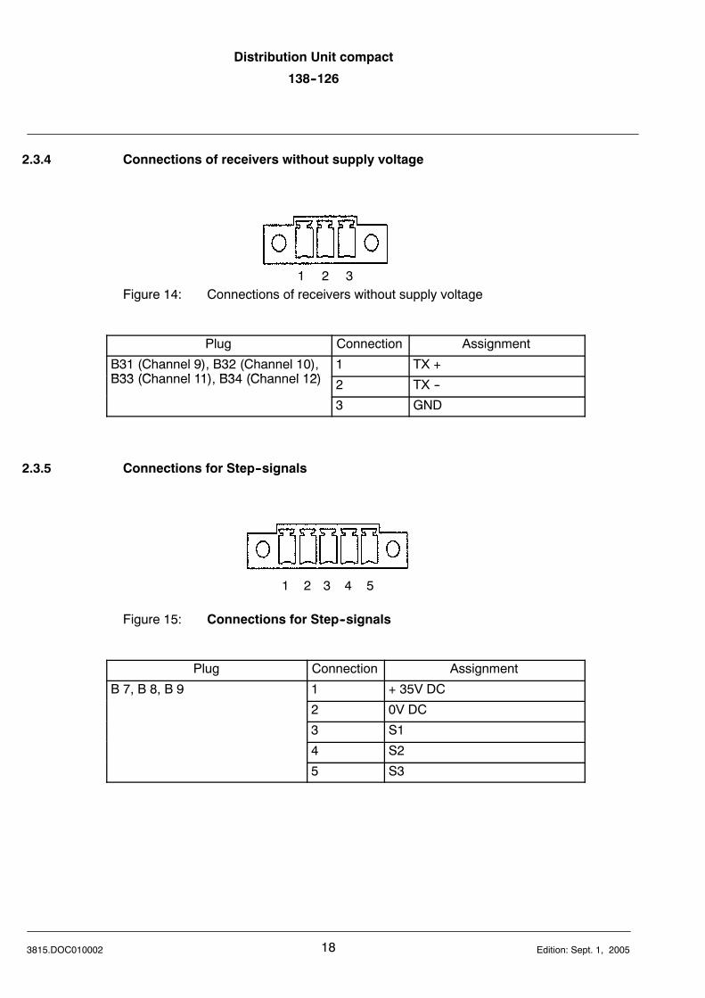
2.3.4 Connections of receivers without supply voltage
1 2 3Figure 14: Connections of receivers without supply voltage
Plug Connection Assignment
B31 (Channel 9), B32 (Channel 10),B33 (Ch l 11) B34 (Ch l 12)
1 TX +B33 (Channel 11), B34 (Channel 12) 2 TX --
3 GND
2.3.5 Connections for Step--signals
1 2 3 4 5
Figure 15: Connections for Step--signals
Plug Connection Assignment
B 7, B 8, B 9 1 + 35V DC
2 0V DC
3 S1
4 S2
5 S3
Distribution Unit compact
138--126DISTRIBUTION
UNIT
19 3815.DOC010002Edition: Sept. 1, 2005
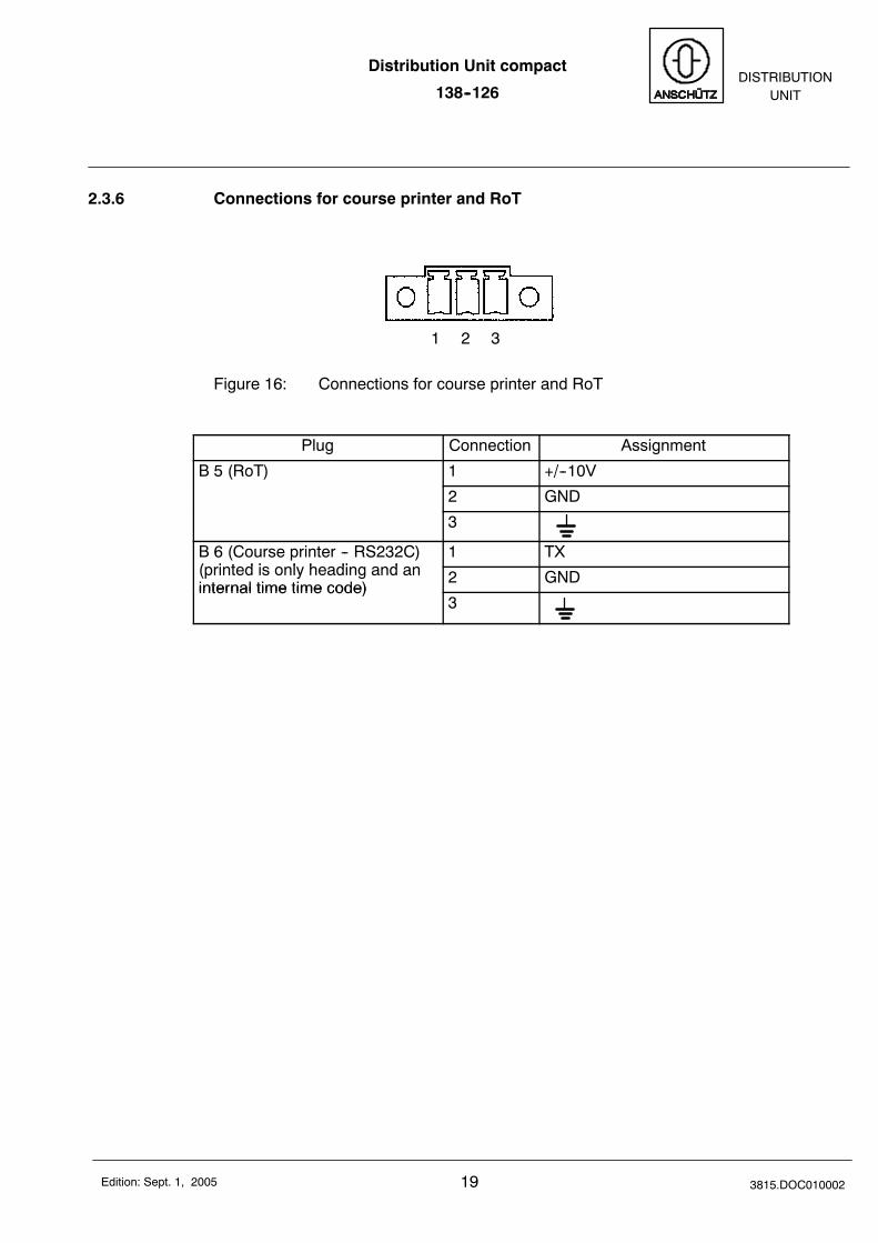
2.3.6 Connections for course printer and RoT
1 2 3
Figure 16: Connections for course printer and RoT
Plug Connection Assignment
B 5 (RoT) 1 +/--10V
2 GND
3
B 6 (Course printer -- RS232C)( i t d i l h di d
1 TX(printed is only heading and aninternal time time code)
2 GNDinternal time time code)
3
Distribution Unit compact
138--126
203815.DOC010002 Edition: Sept. 1, 2005
3 Switching ON of the Distribution Unit compact
After switching ON the mains supply the Distribution Unit compact is switched ON.
A separate switching ON of the Distribution Unit compact is not possible.
Together with a switching ON of the mains supply to the Distribution Unit compact thecompass as well as the connected heading receivers are supplied with operating voltagetoo.
Distribution Unit compact
138--126DISTRIBUTION
UNIT
21 3815.DOC010002Edition: Sept. 1, 2005
4 Configuration
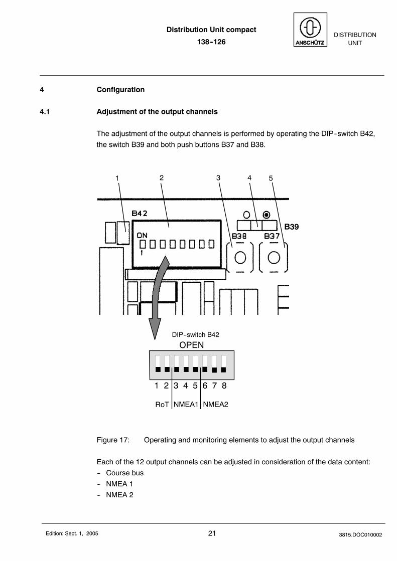
4.1 Adjustment of the output channels
The adjustment of the output channels is performed by operating the DIP--switch B42,the switch B39 and both push buttons B37 and B38.
1 2 3 4 5
1 2 3 4 5 6 7 8
OPENDIP--switch B42
B39
RoT NMEA1 NMEA2
Figure 17: Operating and monitoring elements to adjust the output channels
Each of the 12 output channels can be adjusted in consideration of the data content:-- Course bus-- NMEA 1-- NMEA 2
Distribution Unit compact
138--126
223815.DOC010002 Edition: Sept. 1, 2005
4.1.1 Selection of the output channels
By pushing the switch B39 (Figure 17/4) to the right,switching direction “away from theDIP--switch B42 (Figure 17/2)”, the configuration mode is activated.The LED H60 (Figure 17/1) blinks.With every operation of push button B38 (Figure 17/3) another output channel is se-lected. At the selected channel blinks one of the LED‘s (red, green or blue).
With every operation of the push button B37 (Figure 17/5) the data content of the se-lected output channel is changed (course bus -- NMEA 1 -- NMEA 2).If the red LED blinks then course bus is adjusted to the selected output channel, forNMEA 1 the green LED blinks and for NMEA 2 the blue LED blinks.
By pushing the switch B39 to the left, switching direction to the DIP--switch all adjust-ments are stored and the LED H60 lights up constantly.
Distribution Unit compact
138--126DISTRIBUTION
UNIT
23 3815.DOC010002Edition: Sept. 1, 2005
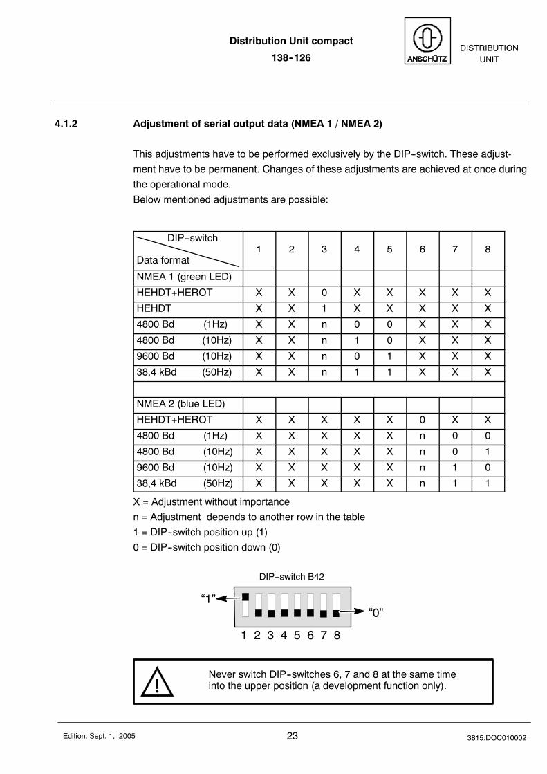
4.1.2 Adjustment of serial output data (NMEA 1 / NMEA 2)
This adjustments have to be performed exclusively by the DIP--switch. These adjust-ment have to be permanent. Changes of these adjustments are achieved at once duringthe operational mode.Below mentioned adjustments are possible:
Data format
DIP--switch1 2 3 4 5 6 7 8
NMEA 1 (green LED)
HEHDT+HEROT X X 0 X X X X X
HEHDT X X 1 X X X X X
4800 Bd (1Hz) X X n 0 0 X X X
4800 Bd (10Hz) X X n 1 0 X X X
9600 Bd (10Hz) X X n 0 1 X X X
38,4 kBd (50Hz) X X n 1 1 X X X
NMEA 2 (blue LED)
HEHDT+HEROT X X X X X 0 X X
4800 Bd (1Hz) X X X X X n 0 0
4800 Bd (10Hz) X X X X X n 0 1
9600 Bd (10Hz) X X X X X n 1 0
38,4 kBd (50Hz) X X X X X n 1 1
X = Adjustment without importancen = Adjustment depends to another row in the table1 = DIP--switch position up (1)0 = DIP--switch position down (0)
1 2 3 4 5 6 7 8
DIP--switch B42
“1”“0”
Never switch DIP--switches 6, 7 and 8 at the same timeinto the upper position (a development function only).
Distribution Unit compact
138--126
243815.DOC010002 Edition: Sept. 1, 2005
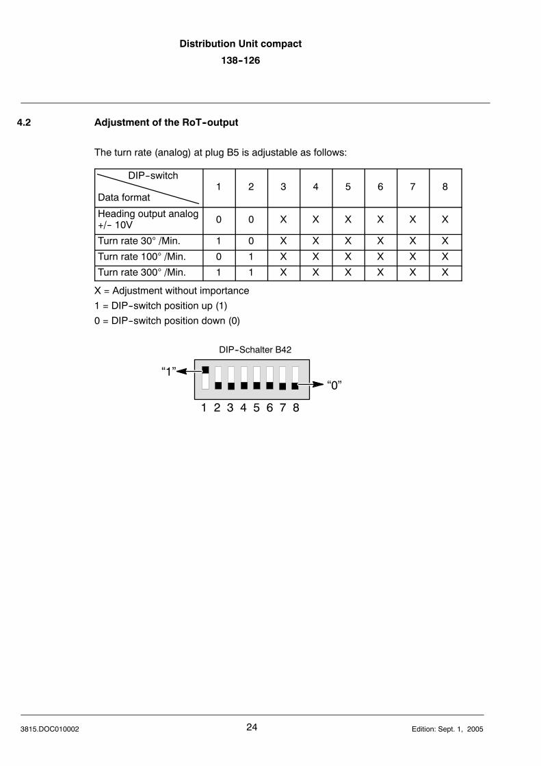
4.2 Adjustment of the RoT--output
The turn rate (analog) at plug B5 is adjustable as follows:
Data format
DIP--switch1 2 3 4 5 6 7 8
Heading output analog+/-- 10V 0 0 X X X X X X
Turn rate 30° /Min. 1 0 X X X X X X
Turn rate 100° /Min. 0 1 X X X X X X
Turn rate 300° /Min. 1 1 X X X X X X
X = Adjustment without importance1 = DIP--switch position up (1)0 = DIP--switch position down (0)
1 2 3 4 5 6 7 8
DIP--Schalter B42
“1”“0”
Distribution Unit compact
138--126DISTRIBUTION
UNIT
25 3815.DOC010002Edition: Sept. 1, 2005
5 Switching OFF the Distribution Unit compact
By switching OFF the mains supply to the Distribution Unit compact, the connected com-pass, all connected heading receivers which are supplied via the Distribution Unit com-pact and the Distribution Unit compact itself are switched OFF.
6 Maintenance and repair
The Distribution Unit compact is maintenance free.A repair is only possible by a replacement of fuses otherwise the Distribution Unit com-pact has to be replaced complete.

Distribution Unit compact
138--126
263815.DOC010002 Edition: Sept. 1, 2005
Intentionally left blank

![Anschutz Katalog_2010_Jagdprogramm[1]](https://static.fdokument.com/doc/165x107/5571f84549795991698d09f6/anschutz-katalog2010jagdprogramm1.jpg)