Robots KR 180--2 KR 210--2 KR 270--2 Spez KR 150--2, 180--2, 210--2, 240--2, KR 240--2 C, 270--2...
68
04.2004.10 Spezifikation Specification Spécification Spez KR 150--2, 180--2, 210--2, 240--2, KR 240--2 C, 270--2 de/en/fr Roboter Robots KR 150--2 KR 180--2 KR 210--2 KR 240--2 KR 240--2 C KR 270--2
Transcript of Robots KR 180--2 KR 210--2 KR 270--2 Spez KR 150--2, 180--2, 210--2, 240--2, KR 240--2 C, 270--2...
04.2004.10
SpezifikationSpecificationSpécification
Spez KR 150--2, 180--2, 210--2, 240--2, KR 240--2 C, 270--2 de/en/fr
RoboterRobots
KR 150--2KR 180--2KR 210--2
KR 240--2KR 240--2 CKR 270--2
Spez KR 150--2, 180--2, 210--2, 240--2, KR 240--2 C, 270--2 de/en/fr 04.2004.102
e Copyright KUKA Roboter GmbH
04.2004.10 Spez KR 150--2, 180--2, 210--2, 240--2, KR 240--2 C, 270--2 de/en/fr 3
Deutsch Seite 3English page 15Français page 27
Inhaltsverzeichnis
1 SYSTEMBESCHREIBUNG 3. . . . .1.1 Allgemeines 3. . . . . . . . . . . . . . . . . . .1.2 Robotermechanik 4. . . . . . . . . . . . . .1.3 Aufstellung 4. . . . . . . . . . . . . . . . . . . .1.4 Austausch 5. . . . . . . . . . . . . . . . . . . .1.5 Transport 5. . . . . . . . . . . . . . . . . . . . .
2 ZUBEHÖR (Auswahl) 6. . . . . . . . .2.1 Roboterbefestigung 6. . . . . . . . . . . .2.2 Zusätzliche Linearachse 6. . . . . . . .2.3 Integrierte Energiezuführung für
Achse 1 6. . . . . . . . . . . . . . . . . . . . . .2.4 Arbeitsbereichsüberwachung 6. . . .2.5 Arbeitsbereichsbegrenzung 6. . . . .2.6 KTL--Justage--Set 6. . . . . . . . . . . . . .2.7 Freidrehvorrichtung für
Roboterachsen 6. . . . . . . . . . . . . . . .2.8 Aufbaugestell 6. . . . . . . . . . . . . . . . .
3 TECHNISCHE DATEN 7. . . . . . . . .
Abbildungen 39--67. . . . . . . . . . . . . . . . .
1 SYSTEMBESCHREIBUNG
1.1 Allgemeines
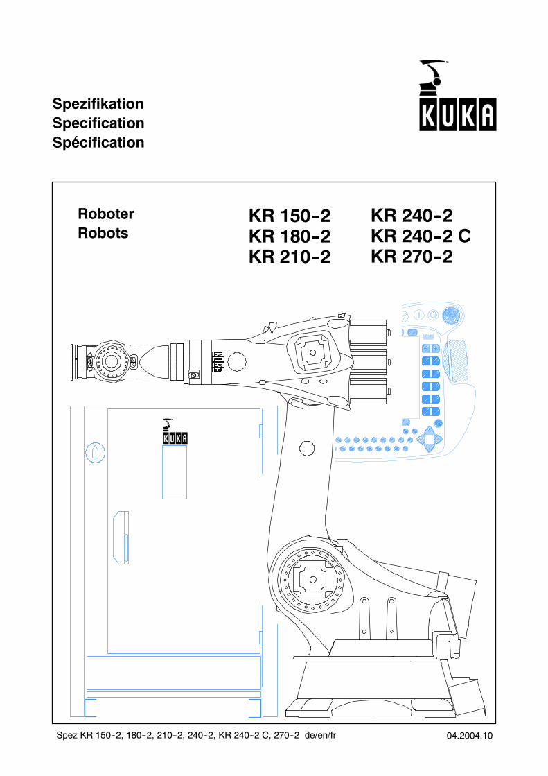
DieRoboter KR 150--2, KR 180--2, KR 210--2, KR240--2 und KR 270--2 (Bild 1--1) sind sechsach-sige Industrieroboter mit Gelenkkinematik für allePunkt-- und Bahnsteuerungsaufgaben. IhreHaupteinsatzgebiete sind-- Punktschweißen-- Handhaben-- Montieren-- Auftragen von Kleb--, Dicht-- und Konservie-
rungsstoffen-- Bearbeiten-- MIG/MAG--Schweißen-- YAG--Laserstrahlschweißen.
Der Roboter KR 240--2 C sowie seine Variantenmit Armverlängerung sind sechsachsige Indu-strieroboter mit Gelenkkinematik für alle Punkt--und Bahnsteuerungsaufgaben. Ihre Hauptein-satzgebiete sind
-- Handhaben von Bauteilen mittels Greifer
-- Montieren von Baugruppen
Die Roboter KR 150--2, KR 180--2, KR 210--2 so-wie deren Variantenmit Armverlängerung können
am Boden und an der Decke eingebaut werden.Der Roboter KR 240--2 sowie dessen Variantenmit Armverlängerung und der KR 270--2 werdenamBoden aufgebaut. Ebenso der KR 180L130--2CR. Der Roboter KR 240--2 C sowie dessen Va-rianten mit Armverlängerung werden an derDecke eingebaut.
Nenn--Traglasten und Zusatzlasten (siehe Ab-schnitt 3 “Technische Daten”) können auch beimaximaler Armausladung mit maximaler Ge-schwindigkeit bewegt werden.
Alle Grundkörper der beweglichen Hauptbau-gruppen bestehen aus Leichtmetallguss. DiesesAuslegungskonzept wurde im Hinblick auf wirt-schaftlichen Leichtbau und hohe Torsions-- undBiegefestigkeit CAD-- und FEM--optimiert. Hier-aus resultiert eine hoheEigenfrequenz des Robo-ters, der dadurch ein gutes dynamisches Verhal-ten mit hoher Schwingungssteifigkeit aufweist.
Gelenke und Getriebe bewegen sich weitgehendspielfrei, alle bewegten Teile sind abgedeckt. AlleAntriebsmotoren sind steckbare, bürstenloseAC--Servomotoren - wartungsfrei und sicher ge-gen Überlastung geschützt.
Die Grundachsen sind dauergeschmiert, d.h. einÖlwechsel ist frühestens nach 20 000 Betriebs-stunden erforderlich.
Alle Roboterkomponenten sind bewusst einfachund übersichtlich gestaltet, in ihrer Anzahl mini-miert und durchweg leicht zugänglich. Der Robo-ter kann auch als komplette Einheit schnell undohne wesentliche Programmkorrektur ausge-tauscht werden. Überkopfbewegungen sindmög-lich.
Durch diese und zahlreiche weitere Konstruk-tionsdetails sind die Roboter schnell und betriebs-sicher, wartungsfreundlich und wartungsarm. Siebenötigen nur wenig Stellfläche und können auf-grund der besonderen Aufbaugeometrie sehrnahe amWerkstück stehen. Die durchschnittlicheLebensdauer liegt, wie bei allen KUKA--Robotern,bei 10 bis 15 Jahren.
Jeder Roboter wird mit einer Steuerung ausgerü-stet, deren Steuer-- und Leistungselektronik in ei-nen gemeinsamen Steuerschrank integriert sind(siehe gesonderte Spezifikation). Sie ist platzspa-rend, anwender-- und servicefreundlich. Der Si-cherheitsstandard entspricht der EU--Maschinen-richtlinie und den einschlägigen Normen (u.a.DIN EN 775).
Spez KR 150--2, 180--2, 210--2, 240--2, KR 240--2 C, 270--2 de/en/fr 04.2004.104
Die Verbindungsleitungen zwischen Roboter undSteuerung enthalten alle hierfür notwendigenVer-sorgungs-- und Signalleitungen. Sie sind am Ro-boter steckbar, auch die Energie-- und Medienlei-tungen für den Betrieb vonWerkzeugen (Zubehör“Integrierte Energiezuführung für Achse 1”).Diese Leitungen sind im Bereich der Grundachse1 fest im Inneren des Roboters installiert.
Bei Bedarf können die Energie-- und Medienlei-tungen für den Betrieb von Werkzeugen mit Hilfevon Systemschnittstellen an den nachgeordnetenAchsen entlang bis zum Werkzeug geführt wer-den.
1.2 Robotermechanik
Der Roboter besteht aus einem feststehendenGrundgestell, auf dem sich um eine senkrechteAchse das “Karussell” mit Schwinge, Arm undHand dreht (Bild 1--1).
Die Hand (Bild 1--2) dient mit ihrem Anbauflanschder Aufnahme von Werkzeugen (z.B. Greifer,Schweißgerät).Die Bewegungsmöglichkeiten der Roboterach-sen gehen aus Bild 1--3 hervor.Die Traglast und das Eigengewicht der Gelenk-komponenten werden durch ein in sich geschlos-senes Gewichtsausgleichssystem statisch weit-gehend ausgeglichen. Es unterstützt die Achse 2.Durch Nachrüsten eines Umbausatzes (Zubehör)kann je nach Traglast und Zusatzlast des Einsatz-falls und je nach Einbaulage des Roboters dieWirksamkeit variiert werden.Die Wegmessung für die Grund-- und Handach-sen (A 1 bis A 3 bzw. A 4 bis A 6) erfolgt über einzyklisch absolutes Wegmesssystem mit einemResolver für jede Achse.Der Antrieb erfolgt durch transistorgesteuerte,trägheitsarme AC--Servomotoren. In die Motor-einheiten sind Bremse und Resolver raumspa-rend integriert.Der Arbeitsbereich des Roboters wird in allenAchsen über Software--Endschalter begrenzt.Mechanisch werden die Arbeitsbereiche der Ach-sen 1, 2, 3 und 5 über Endanschläge mit Puffer-funktion begrenzt.Als Zubehör “Arbeitsbereichsbegrenzung” sindfür die Achsen 1 bis 3mechanische Anschläge füreine aufgabenbedingte Begrenzung des jeweili-gen Arbeitsbereichs lieferbar.Für größere Anforderungen an mechanische undthermische Belastung steht die Zentralhand-variante “F” zur Verfügung. Sie ist umfangreicherabgedichtet und mit korrosionsbeständigen Bau-teilen ausgestattet. Zum Erhalt der Belastbarkeitsind kürzere Wartungsintervalle einzuhalten.
Bei Robotern der “F”--Variante ist der Arm druck-beaufschlagt. Er wird mit einem Innendruck von0,1 bar betrieben.
In Clean--Room--Umgebung kommt die VarianteKR 180 L130--2 CR mit ZH 130 CR zum Einsatz.Durch umfangreiche Modifikationen ist die Parti-kelemission gegenüber der Standardversiondeutlich reduziert. Außerdem ist der Roboter mitkorrosionsbeständigen Bauteilen ausgestattet.
1.3 Aufstellung
Für die Aufstellung des Roboters gibt es mehrereMöglichkeiten:
-- Variante 1
Diese Variante ist mit Fundamentplatten, Auf-nahmebolzen, Dübeln und Schrauben als Zu-behör “Fundamentbefestigungssatz” lieferbar.Der Roboter wird mit vier Fundamentplatten(Bild 1--4) auf den vorbereiteten Hallenbodengesetzt. Seine Einbauposition wird durch zweiAufnahmebolzen bestimmt, was seinewieder-holbare Austauschbarkeit ermöglicht. Die Be-festigung des Roboters erfolgt mit achtSchrauben auf den Fundamentplatten.Die Fundamentplatten werden vor dem Auf-setzen des Roboters mit je drei Dübelschrau-ben am Hallenboden befestigt.
-- Variante 2
Diese Variante ist mit Aufnahmebolzen undSchrauben als Zubehör “Maschinengestellbe-festigungssatz” lieferbar. Der Roboter wird aufeine vorbereitete Stahlkonstruktion gesetztund mit acht Schrauben festgeschraubt (Bild1--5). Seine Einbauposition wird durch zweiAufnahmebolzen bestimmt, was seinewieder-holbare Austauschbarkeit ermöglicht.
-- Variante 3
Diese Variante ist mit Aufbaugestell, Aufnah-mebolzen, Klebedübeln und Schrauben alsZubehör “Aufbaugestell” lieferbar.DasAufbaugestell wirdmit 16 Klebedübeln aufdem vorbereiteten Hallenboden befestigt (Bild1--6). Die Befestigung des Roboters erfolgt mitacht Schrauben auf dem Aufbaugestell. DieEinbauposition des Roboters wird durch zweiAufnahmebolzen bestimmt, was seinewieder-holbare Austauschbarkeit ermöglicht.
ACHTUNG bei Variante 1 und 3:Bei der Vorbereitung eines Fundaments sinddie einschlägigen Bauvorschriften hinsicht-lich Betonqualität (≥ B 25 nach DIN 1045:1988oder C20/25 nach DIN EN 206--1:2001/DIN1045--2:2001) und Tragfähigkeit des Unter-grunds zu beachten. Bei der Anfertigung ist
04.2004.10 Spez KR 150--2, 180--2, 210--2, 240--2, KR 240--2 C, 270--2 de/en/fr 5
auf eine ebene und ausreichend glatte Ob-erfläche zu achten.Das Einbringen der Klebedübel muss sehrsorgfältig erfolgen, damit die während desBetriebs auftretenden Kräfte (Bild 1--7) sicherin den Boden geleitet werden. Das Bild 1--7kann auch für weitergehende statische Unter-suchungen herangezogen werden.
1.4 Austausch
Bei Produktionsanlagen mit einer größeren An-zahl vonRobotern ist die problemlose Austausch-barkeit der Roboter untereinander von Bedeu-tung. Sie wird gewährleistet
-- durch die Reproduzierbarkeit der werkseitigmarkierten Synchronisationsstellungen allerAchsen, der sogenannten mechanischenNull--Stellungen, und
-- durch die rechnerunterstützte Nullpunktju-stage,
und sie wird zusätzlich begünstigt
-- durch eine fernab vom Roboter und vorwegdurchführbare Offline--Programmierung sowie
-- durch die reproduzierbare Aufstellung des Ro-boters.
Service-- und Wartungsarbeiten (u.a. die Handund die Motoren betreffend) erfordern abschlie-ßend die Herbeiführung der elektrischen und dermechanischen Null--Stellung (Kalibrierung) desRoboters. Zu diesem Zweck sind werkseitigMesspatronen an jeder Roboterachse ange-bracht.
Das Einstellen der Messpatronen ist Teil der Ver-messungsarbeiten vor Auslieferung des Robo-ters. Dadurch, dass an jeder Achse immermit der-selben Patrone gemessen wird, erreicht man einHöchstmaß an Genauigkeit beim erstmaligenVermessen und beim späteren Wiederaufsuchender mechanischen Null--Stellung.
Für das Sichtbarmachen der Stellung des in derMesspatrone liegenden Tasters wird als Zubehörein elektronischer Messtaster (KTL--Justage--Set) auf dieMesspatrone geschraubt. BeimÜber-fahren der Messkerbe während des Einstellvor-gangs wird dasWegmesssystem automatischaufelektrisch Null gesetzt.
Nach vollzogener Nullpunkt--Einstellung für alleAchsen kann der Roboter wieder in Betrieb ge-nommen werden.
Die geschilderten Vorgängeermöglichen es, dassdie einmal festgelegten Programme jederzeit aufjeden anderen Roboter desselben Typs übertra-gen werden können.
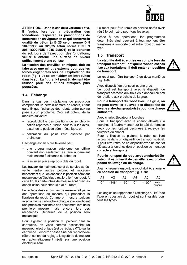
1.5 Transport
Beim Transport des Roboters ist auf dieStandsicherheit zu achten. SolangederRobo-ter nicht auf dem Fundament befestigt ist,muss er in Transportstellung gehalten wer-den.Der Roboter kann auf zweierlei Weise transpor-tiert werden (Bild 1--8):Mit Transportgeschirr und KranDer Roboter lässt sich mit einem Transportge-schirr, das in drei Ringschrauben am Karusselleingehängt wird, an den Kranhaken hängen undso transportieren.
Für den Transport des Roboters mittels Krandürfen nur zugelassene Last-- und Hebege-schirre mit ausreichender Traglast verwendetwerden.
Mit GabelstaplerFür den Transport mit dem Gabelstapler müssenzwei Gabelstaplertaschen (Zubehör) an das Ka-russell angebaut werden.Für die Befestigung an der Decke wird der Robo-ter in einem speziellen Transportgestell hängendgeliefert. Aus diesem kann ermit demGabelstap-ler bereits in richtiger Einbaulage entnommen undweitertransportiert werden.
Für den Transport des Roboters mittels Ga-belstapler dürfen keine Last-- oder Hebege-schirre verwendet werden.
Vor jedem Transport muss der Roboter in Trans-portstellung gebracht werden (Bild 1--9):
A1 A2 A3 A4 A5 A6
0˚ --146˚ +150˚ 0˚ ---100˚ beliebig
Diese Winkelangaben gelten für alle beschriebe-nen Robotertypen und beziehen sich auf dieAnzeigeamDisplaydesKCPfürdie jeweiligeRo-boterachse.
Spez KR 150--2, 180--2, 210--2, 240--2, KR 240--2 C, 270--2 de/en/fr 04.2004.106
Maße für dieVerpackungdesRoboters imContai-ner:
Robotertyp L(mm)
B(mm)
H(mm)
KR 150--2 1723 1184 1671KR 150 L130--2 1923 1184 1671KR 150 L110--2 2122 1184 1671KR 180--2 1723 1184 1671KR 180 L150--2 1923 1184 1671KR 180 L130--2 2122 1184 1671KR 210--2 1723 1184 1671KR 210 L180--2 1923 1184 1671KR 210 L150--2 2122 1184 1671KR 240--2 1723 1184 1671KR 240 L210--2 1923 1184 1671KR 240 L180--2 2122 1184 1671KR 240--2 C 1723 1184 1671KR 240 L210--2 C 1723 1184 1671KR 240 L180--2 C 1723 1184 1671KR 270--2 1723 1184 1671
2 ZUBEHÖR (Auswahl)
2.1 Roboterbefestigung
Die Befestigung des Roboters kann in drei Varian-ten erfolgen:-- mit Fundamentbefestigungssatz (Bild 1--4)-- mit Maschinengestellbefestigungssatz (Bild 1--5)-- mit Aufbaugestell (Bild 1--6).Beschreibung siehe Abschnitt 1.3.
2.2 Zusätzliche Linearachse
Mit Hilfe einer Lineareinheit als zusätzlicheFahrachse auf der Basis der Baureihe KL 1500(Bild 2--1) kann der Roboter translatorisch und freiprogrammierbar verfahren werden -- am Bodenoder an der Decke.
2.3 Integrierte Energiezuführung fürAchse 1
Es stehen verschiedene Energiezuführungen zurVerfügung, unter anderem für die Applikationen“Handhaben” und “Punktschweißen”. Die ent-sprechenden Leitungen verlaufen im Bereich derAchse 1 innerhalb des Roboters vom Steckerfeldbis zu einer Schnittstelle am Karussell (Bild 2--2).
Von dort können zusätzliche Leitungen außen anSchwinge und Arm entlang bis zu einer entspre-chenden Schnittstelle am Werkzeug geführt wer-den. Damit entfällt der raumaufwendige Versor-gungsgalgen.
2.4 Arbeitsbereichsüberwachung
StandardausführungDie Achsen 1 bis 3 können mit Positionsschalternoder Initiatoren und Nutenringen, auf denen ver-stellbare Nocken befestigt sind, ausgerüstet wer-den. Das ermöglicht die ständige Überwachungder Roboterstellung.
Bei Achse 1 können drei Sektoren, bei Achse 2zwei Sektoren und bei Achse 3 ein Sektor des je-weiligen Bewegungsbereichs überwacht werden.
Werden die Achsen 2 oder 3 mit einer Arbeitsbe-reichsüberwachung ausgestattet, ist eine “Ener-giezuführung für Achse 1” mit einer zusätzlichenSteuerleitung erforderlich.
2.5 Arbeitsbereichsbegrenzung
Die Bewegungsbereiche der Achsen 1 bis 3 kön-nen mit zusätzlichen mechanischen Anschlägenaufgabenbedingt begrenzt werden.
2.6 KTL--Justage--Set
Um eine für alle Achsen notwendige Nullpunkt--Einstellung durchzuführen, kann der zu einemKTL--Justage--Set gehörende elektronischeMesstaster (Bild 2--3 und 3--19) verwendet wer-den. Er erlaubt ein besonders schnelles, einfa-ches Messen sowie eine automatische, rechner-gestützte Justage und sollte bei derRoboterbestellung mitbestellt werden.
2.7 Freidrehvorrichtung fürRoboterachsen
Mit dieser Vorrichtung kann der Roboter nacheinem Störfall mechanisch über die Grundachs--Antriebsmotoren und die Handachs--Antriebsmo-toren bewegt werden. Sie sollte nur in Notfällen(z. B. Befreiung von Personen) verwendet wer-den.
2.8 Aufbaugestell
Das Aufbaugestell (Bild 2--4) ist eine Stahlkon-struktion und dient zur Befestigung des Roboters(siehe auch Abschnitt 1.3 “Aufstellung, Variante3”). Es ist in Höhen von 150 mm bis 1950 mm inAbstufungen von 150 mm lieferbar.
04.2004.10 Spez KR 150--2, 180--2, 210--2, 240--2, KR 240--2 C, 270--2 de/en/fr 7
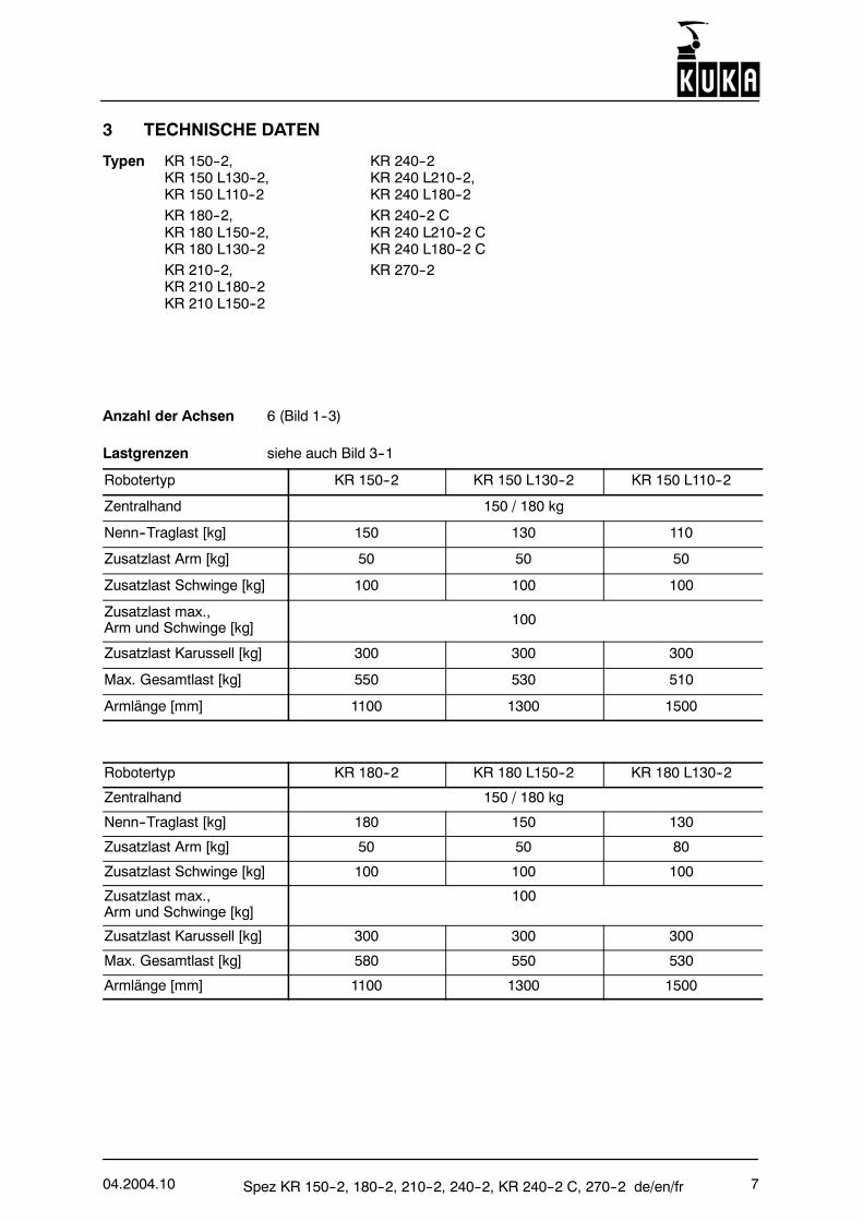
3 TECHNISCHE DATEN
Typen KR 150--2, KR 240--2KR 150 L130--2, KR 240 L210--2,KR 150 L110--2 KR 240 L180--2KR 180--2, KR 240--2 CKR 180 L150--2, KR 240 L210--2 CKR 180 L130--2 KR 240 L180--2 CKR 210--2, KR 270--2KR 210 L180--2KR 210 L150--2
Anzahl der Achsen 6 (Bild 1--3)
Lastgrenzen siehe auch Bild 3--1
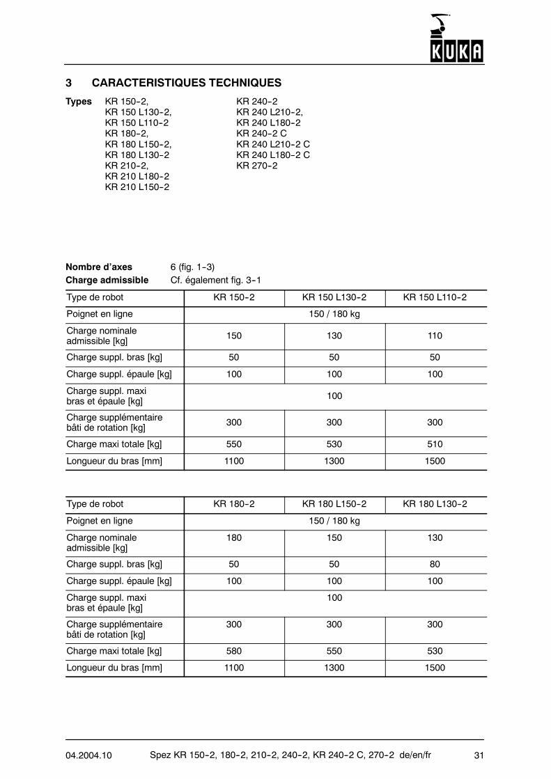
Robotertyp KR 150--2 KR 150 L130--2 KR 150 L110--2
Zentralhand 150 / 180 kg
Nenn--Traglast [kg] 150 130 110
Zusatzlast Arm [kg] 50 50 50
Zusatzlast Schwinge [kg] 100 100 100
Zusatzlast max.,Arm und Schwinge [kg] 100
Zusatzlast Karussell [kg] 300 300 300
Max. Gesamtlast [kg] 550 530 510
Armlänge [mm] 1100 1300 1500
Robotertyp KR 180--2 KR 180 L150--2 KR 180 L130--2
Zentralhand 150 / 180 kg
Nenn--Traglast [kg] 180 150 130
Zusatzlast Arm [kg] 50 50 80
Zusatzlast Schwinge [kg] 100 100 100
Zusatzlast max.,Arm und Schwinge [kg]
100
Zusatzlast Karussell [kg] 300 300 300
Max. Gesamtlast [kg] 580 550 530
Armlänge [mm] 1100 1300 1500
Spez KR 150--2, 180--2, 210--2, 240--2, KR 240--2 C, 270--2 de/en/fr 04.2004.108
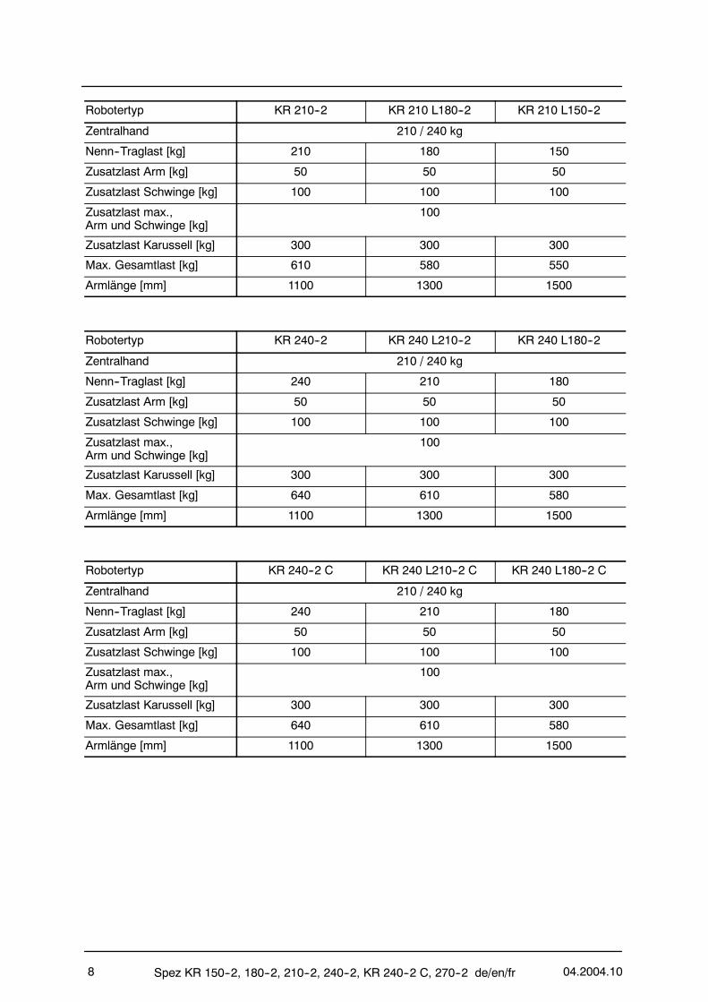
Robotertyp KR 210--2 KR 210 L180--2 KR 210 L150--2
Zentralhand 210 / 240 kg
Nenn--Traglast [kg] 210 180 150
Zusatzlast Arm [kg] 50 50 50
Zusatzlast Schwinge [kg] 100 100 100
Zusatzlast max.,Arm und Schwinge [kg]
100
Zusatzlast Karussell [kg] 300 300 300
Max. Gesamtlast [kg] 610 580 550
Armlänge [mm] 1100 1300 1500
Robotertyp KR 240--2 KR 240 L210--2 KR 240 L180--2
Zentralhand 210 / 240 kg
Nenn--Traglast [kg] 240 210 180
Zusatzlast Arm [kg] 50 50 50
Zusatzlast Schwinge [kg] 100 100 100
Zusatzlast max.,Arm und Schwinge [kg]
100
Zusatzlast Karussell [kg] 300 300 300
Max. Gesamtlast [kg] 640 610 580
Armlänge [mm] 1100 1300 1500
Robotertyp KR 240--2 C KR 240 L210--2 C KR 240 L180--2 C
Zentralhand 210 / 240 kg
Nenn--Traglast [kg] 240 210 180
Zusatzlast Arm [kg] 50 50 50
Zusatzlast Schwinge [kg] 100 100 100
Zusatzlast max.,Arm und Schwinge [kg]
100
Zusatzlast Karussell [kg] 300 300 300
Max. Gesamtlast [kg] 640 610 580
Armlänge [mm] 1100 1300 1500
04.2004.10 Spez KR 150--2, 180--2, 210--2, 240--2, KR 240--2 C, 270--2 de/en/fr 9
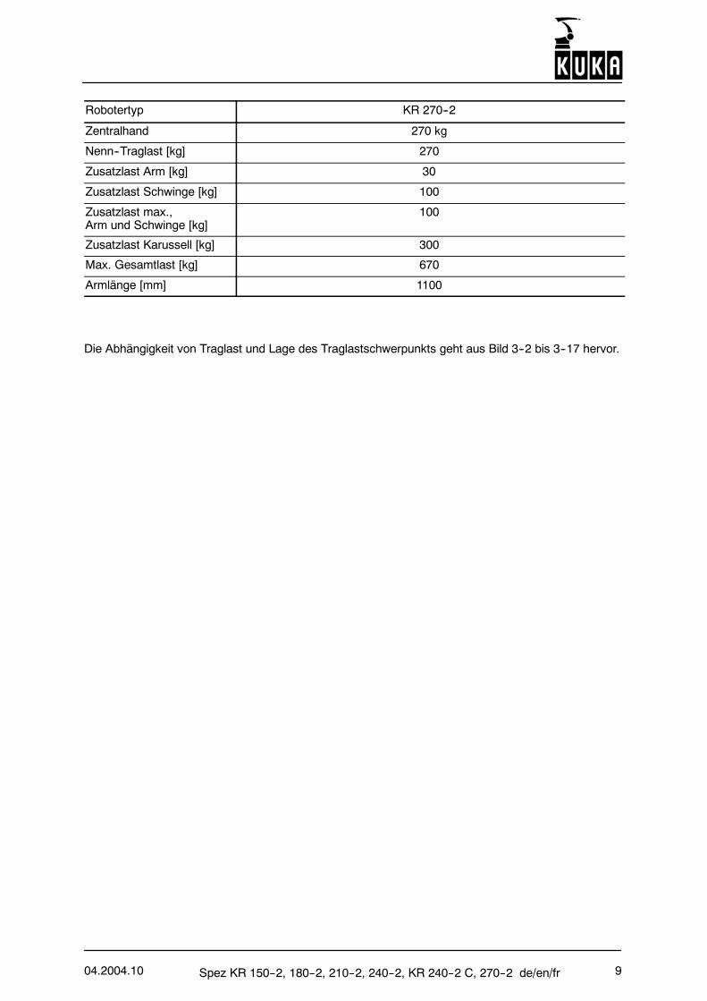
Robotertyp KR 270--2
Zentralhand 270 kg
Nenn--Traglast [kg] 270
Zusatzlast Arm [kg] 30
Zusatzlast Schwinge [kg] 100
Zusatzlast max.,Arm und Schwinge [kg]
100
Zusatzlast Karussell [kg] 300
Max. Gesamtlast [kg] 670
Armlänge [mm] 1100
Die Abhängigkeit von Traglast und Lage des Traglastschwerpunkts geht aus Bild 3--2 bis 3--17 hervor.
Spez KR 150--2, 180--2, 210--2, 240--2, KR 240--2 C, 270--2 de/en/fr 04.2004.1010
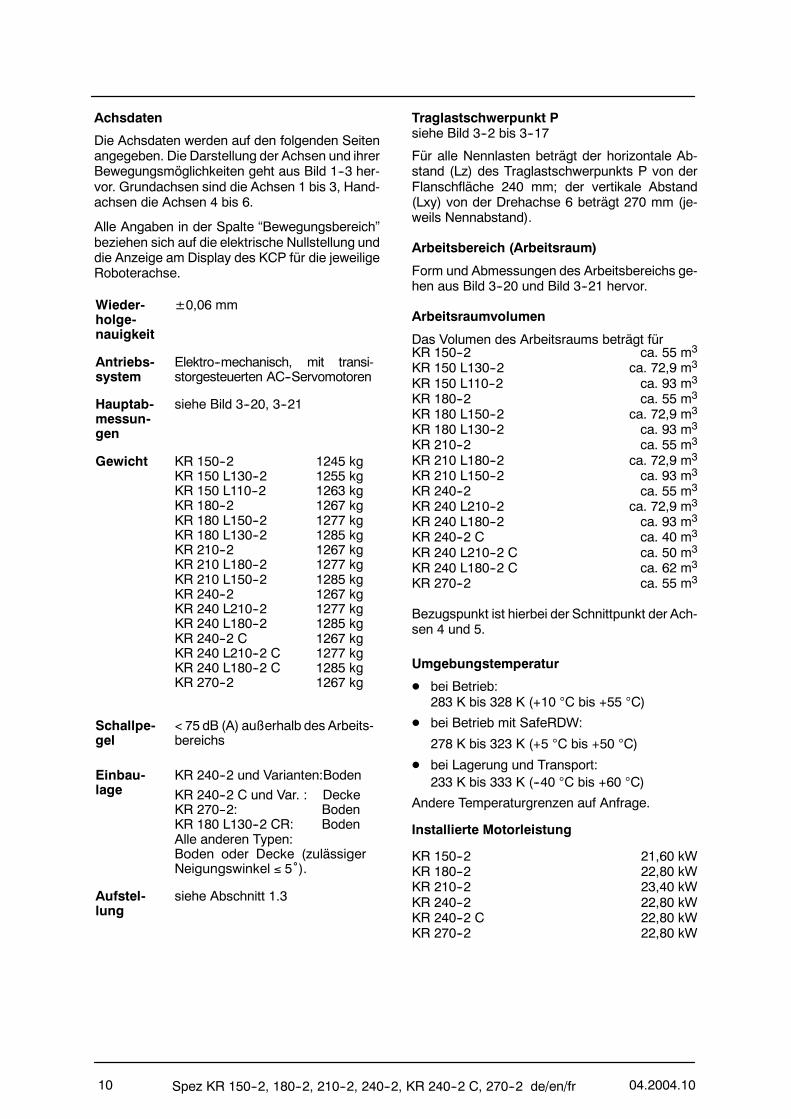
Achsdaten
Die Achsdaten werden auf den folgenden Seitenangegeben. Die Darstellung der Achsen und ihrerBewegungsmöglichkeiten geht aus Bild 1--3 her-vor. Grundachsen sind die Achsen 1 bis 3, Hand-achsen die Achsen 4 bis 6.
Alle Angaben in der Spalte “Bewegungsbereich”beziehen sich auf die elektrische Nullstellung unddie Anzeige am Display des KCP für die jeweiligeRoboterachse.
Wieder-holge-nauigkeit
±0,06 mm
Antriebs-system
Elektro--mechanisch, mit transi-storgesteuerten AC--Servomotoren
Hauptab-messun-gen
siehe Bild 3--20, 3--21
Gewicht KR 150--2 1245 kgKR 150 L130--2 1255 kgKR 150 L110--2 1263 kgKR 180--2 1267 kgKR 180 L150--2 1277 kgKR 180 L130--2 1285 kgKR 210--2 1267 kgKR 210 L180--2 1277 kgKR 210 L150--2 1285 kgKR 240--2 1267 kgKR 240 L210--2 1277 kgKR 240 L180--2 1285 kgKR 240--2 C 1267 kgKR 240 L210--2 C 1277 kgKR 240 L180--2 C 1285 kgKR 270--2 1267 kg
Schallpe-gel
< 75 dB (A) außerhalb des Arbeits-bereichs
Einbau-lage
KR 240--2 und Varianten:Boden
KR 240--2 C und Var. : DeckeKR 270--2: BodenKR 180 L130--2 CR: BodenAlle anderen Typen:Boden oder Decke (zulässigerNeigungswinkel ≤ 5˚).
Aufstel-lung
siehe Abschnitt 1.3
Traglastschwerpunkt Psiehe Bild 3--2 bis 3--17
Für alle Nennlasten beträgt der horizontale Ab-stand (Lz) des Traglastschwerpunkts P von derFlanschfläche 240 mm; der vertikale Abstand(Lxy) von der Drehachse 6 beträgt 270 mm (je-weils Nennabstand).
Arbeitsbereich (Arbeitsraum)
Form und Abmessungen des Arbeitsbereichs ge-hen aus Bild 3--20 und Bild 3--21 hervor.
Arbeitsraumvolumen
Das Volumen des Arbeitsraums beträgt fürKR 150--2 ca. 55 m3
KR 150 L130--2 ca. 72,9 m3
KR 150 L110--2 ca. 93 m3
KR 180--2 ca. 55 m3
KR 180 L150--2 ca. 72,9 m3
KR 180 L130--2 ca. 93 m3
KR 210--2 ca. 55 m3
KR 210 L180--2 ca. 72,9 m3
KR 210 L150--2 ca. 93 m3
KR 240--2 ca. 55 m3
KR 240 L210--2 ca. 72,9 m3
KR 240 L180--2 ca. 93 m3
KR 240--2 C ca. 40 m3
KR 240 L210--2 C ca. 50 m3
KR 240 L180--2 C ca. 62 m3
KR 270--2 ca. 55 m3
Bezugspunkt ist hierbei der Schnittpunkt der Ach-sen 4 und 5.
Umgebungstemperatur
D bei Betrieb:283 K bis 328 K (+10 °C bis +55 °C)
D bei Betrieb mit SafeRDW:
278 K bis 323 K (+5 °C bis +50 °C)
D bei Lagerung und Transport:233 K bis 333 K (--40 °C bis +60 °C)
Andere Temperaturgrenzen auf Anfrage.
Installierte Motorleistung
KR 150--2 21,60 kWKR 180--2 22,80 kWKR 210--2 23,40 kWKR 240--2 22,80 kWKR 240--2 C 22,80 kWKR 270--2 22,80 kW
04.2004.10 Spez KR 150--2, 180--2, 210--2, 240--2, KR 240--2 C, 270--2 de/en/fr 11
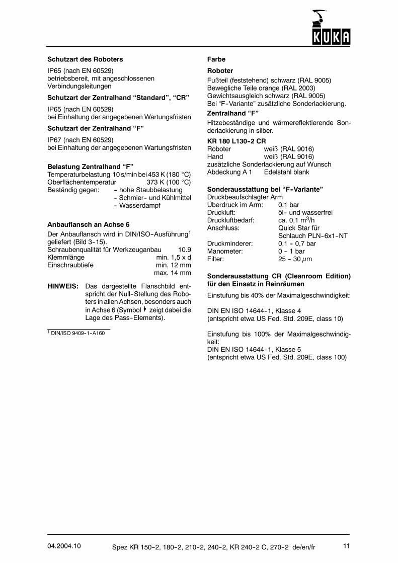
Schutzart des Roboters
IP65 (nach EN 60529)betriebsbereit, mit angeschlossenenVerbindungsleitungen
Schutzart der Zentralhand “Standard”, “CR”
IP65 (nach EN 60529)bei Einhaltung der angegebenen Wartungsfristen
Schutzart der Zentralhand “F”
IP67 (nach EN 60529)bei Einhaltung der angegebenen Wartungsfristen
Belastung Zentralhand “F”Temperaturbelastung 10 s/min bei 453 K (180 °C)Oberflächentemperatur 373 K (100 °C)Beständig gegen: -- hohe Staubbelastung
-- Schmier-- und Kühlmittel-- Wasserdampf
Anbauflansch an Achse 6Der Anbauflansch wird in DIN/ISO--Ausführung1
geliefert (Bild 3--15).Schraubenqualität für Werkzeuganbau 10.9Klemmlänge min. 1,5 x dEinschraubtiefe min. 12 mm
max. 14 mm
HINWEIS: Das dargestellte Flanschbild ent-spricht der Null--Stellung des Robo-ters in allenAchsen, besonders auchin Achse 6 (Symbol zeigt dabei dieLage des Pass--Elements).
1 DIN/ISO 9409--1--A160
Farbe
RoboterFußteil (feststehend) schwarz (RAL 9005)Bewegliche Teile orange (RAL 2003)Gewichtsausgleich schwarz (RAL 9005)Bei “F--Variante” zusätzliche Sonderlackierung.Zentralhand “F”Hitzebeständige und wärmereflektierende Son-derlackierung in silber.
KR 180 L130--2 CRRoboter weiß (RAL 9016)Hand weiß (RAL 9016)zusätzliche Sonderlackierung auf WunschAbdeckung A 1 Edelstahl blank
Sonderausstattung bei “F--Variante”Druckbeaufschlagter ArmÜberdruck im Arm: 0,1 barDruckluft: öl-- und wasserfreiDruckluftbedarf: ca. 0,1 m3/hAnschluss: Quick Star für
Schlauch PLN--6x1--NTDruckminderer: 0,1 -- 0,7 barManometer: 0 -- 1 barFilter: 25 -- 30 µm
Sonderausstattung CR (Cleanroom Edition)für den Einsatz in Reinräumen
Einstufung bis 40% der Maximalgeschwindigkeit:
DIN EN ISO 14644--1, Klasse 4(entspricht etwa US Fed. Std. 209E, class 10)
Einstufung bis 100% der Maximalgeschwindig-keit:DIN EN ISO 14644--1, Klasse 5(entspricht etwa US Fed. Std. 209E, class 100)
Spez KR 150--2, 180--2, 210--2, 240--2, KR 240--2 C, 270--2 de/en/fr 04.2004.1012
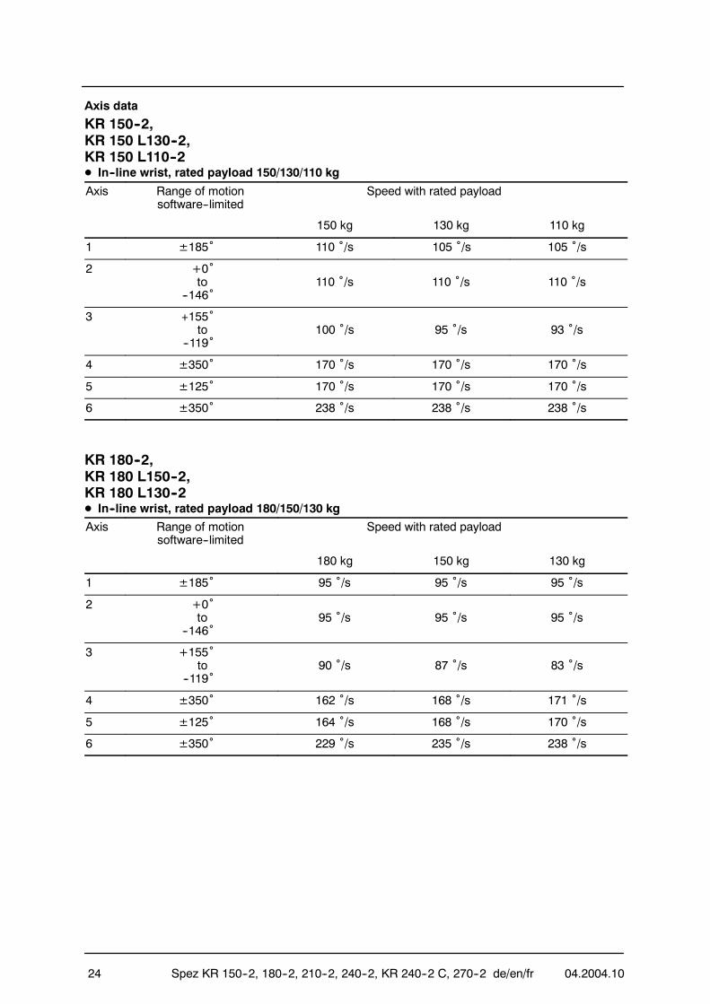
Achsdaten
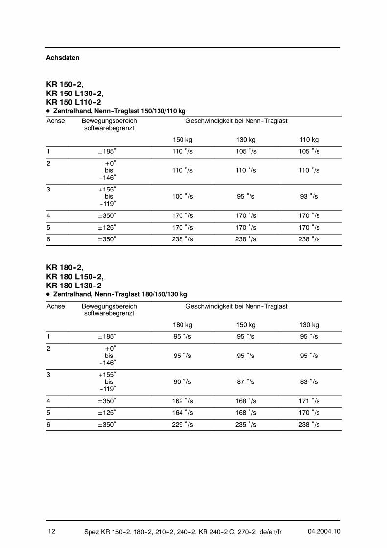
KR 150--2,KR 150 L130--2,KR 150 L110--2D Zentralhand, Nenn--Traglast 150/130/110 kg
Achse Bewegungsbereichsoftwarebegrenzt
Geschwindigkeit bei Nenn--Traglast
150 kg 130 kg 110 kg
1 ±185˚ 110 ˚/s 105 ˚/s 105 ˚/s
2 +0˚bis
--146˚110 ˚/s 110 ˚/s 110 ˚/s
3 +155˚bis
--119˚100 ˚/s 95 ˚/s 93 ˚/s
4 ±350˚ 170 ˚/s 170 ˚/s 170 ˚/s
5 ±125˚ 170 ˚/s 170 ˚/s 170 ˚/s
6 ±350˚ 238 ˚/s 238 ˚/s 238 ˚/s
KR 180--2,KR 180 L150--2,KR 180 L130--2D Zentralhand, Nenn--Traglast 180/150/130 kg
Achse Bewegungsbereichsoftwarebegrenzt
Geschwindigkeit bei Nenn--Traglast
180 kg 150 kg 130 kg
1 ±185˚ 95 ˚/s 95 ˚/s 95 ˚/s
2 +0˚bis
--146˚95 ˚/s 95 ˚/s 95 ˚/s
3 +155˚bis
--119˚90 ˚/s 87 ˚/s 83 ˚/s
4 ±350˚ 162 ˚/s 168 ˚/s 171 ˚/s
5 ±125˚ 164 ˚/s 168 ˚/s 170 ˚/s
6 ±350˚ 229 ˚/s 235 ˚/s 238 ˚/s

04.2004.10 Spez KR 150--2, 180--2, 210--2, 240--2, KR 240--2 C, 270--2 de/en/fr 13
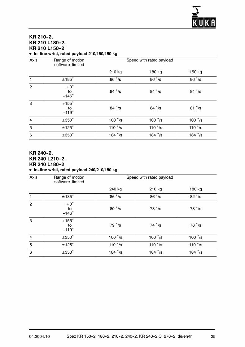
KR 210--2,KR 210 L180--2,KR 210 L150--2D Zentralhand, Nenn--Traglast 210/180/150 kg
Achse Bewegungsbereichsoftwarebegrenzt
Geschwindigkeit bei Nenn--Traglast
210 kg 180 kg 150 kg
1 ±185˚ 86 ˚/s 86 ˚/s 86 ˚/s
2 +0˚bis
--146˚84 ˚/s 84 ˚/s 84 ˚/s
3 +155˚bis
--119˚84 ˚/s 84 ˚/s 81 ˚/s
4 ±350˚ 100 ˚/s 100 ˚/s 100 ˚/s
5 ±125˚ 110 ˚/s 110 ˚/s 110 ˚/s
6 ±350˚ 184 ˚/s 184 ˚/s 184 ˚/s
KR 240--2,KR 240 L210--2,KR 240 L180--2D Zentralhand, Nenn--Traglast 240/210/180 kg
Achse Bewegungsbereichsoftwarebegrenzt
Geschwindigkeit bei Nenn--Traglast
240 kg 210 kg 180 kg
1 ±185˚ 86 ˚/s 82 ˚/s 82 ˚/s
2 +0˚bis
--146˚80 ˚/s 78 ˚/s 78 ˚/s
3 +155˚bis
--119˚79 ˚/s 74 ˚/s 76 ˚/s
4 ±350˚ 100 ˚/s 100 ˚/s 100 ˚/s
5 ±125˚ 110 ˚/s 110 ˚/s 110 ˚/s
6 ±350˚ 184 ˚/s 184 ˚/s 184 ˚/s
Spez KR 150--2, 180--2, 210--2, 240--2, KR 240--2 C, 270--2 de/en/fr 04.2004.1014
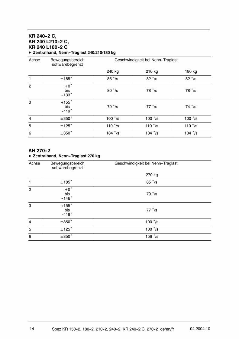
KR 240--2 C,KR 240 L210--2 C,KR 240 L180--2 CD Zentralhand, Nenn--Traglast 240/210/180 kg
Achse Bewegungsbereichsoftwarebegrenzt
Geschwindigkeit bei Nenn--Traglast
240 kg 210 kg 180 kg
1 ±185˚ 86 ˚/s 82 ˚/s 82 ˚/s
2 +0˚bis
--133˚80 ˚/s 78 ˚/s 78 ˚/s
3 +155˚bis
--119˚79 ˚/s 77 ˚/s 74 ˚/s
4 ±350˚ 100 ˚/s 100 ˚/s 100 ˚/s
5 ±125˚ 110 ˚/s 110 ˚/s 110 ˚/s
6 ±350˚ 184 ˚/s 184 ˚/s 184 ˚/s
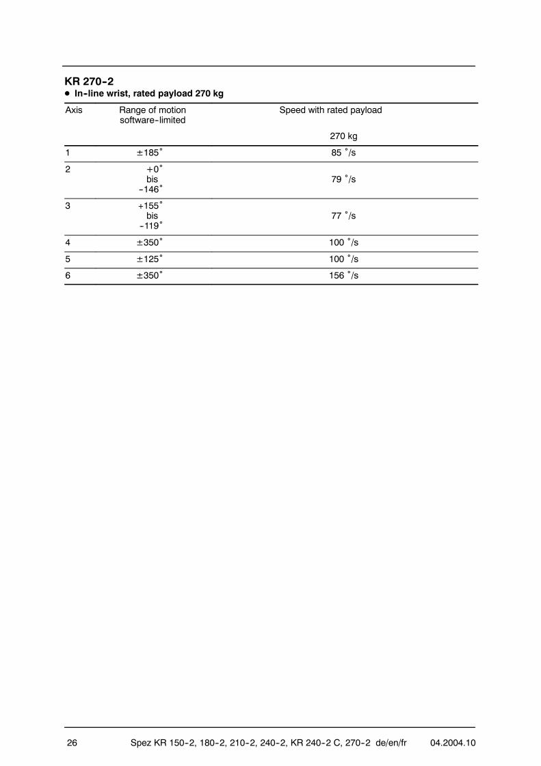
KR 270--2D Zentralhand, Nenn--Traglast 270 kg
Achse Bewegungsbereichsoftwarebegrenzt
Geschwindigkeit bei Nenn--Traglast
270 kg
1 ±185˚ 85 ˚/s
2 +0˚bis
--146˚79 ˚/s
3 +155˚bis
--119˚77 ˚/s
4 ±350˚ 100 ˚/s
5 ±125˚ 100 ˚/s
6 ±350˚ 156 ˚/s
04.2004.10 Spez KR 150--2, 180--2, 210--2, 240--2, KR 240--2 C, 270--2 de/en/fr 15
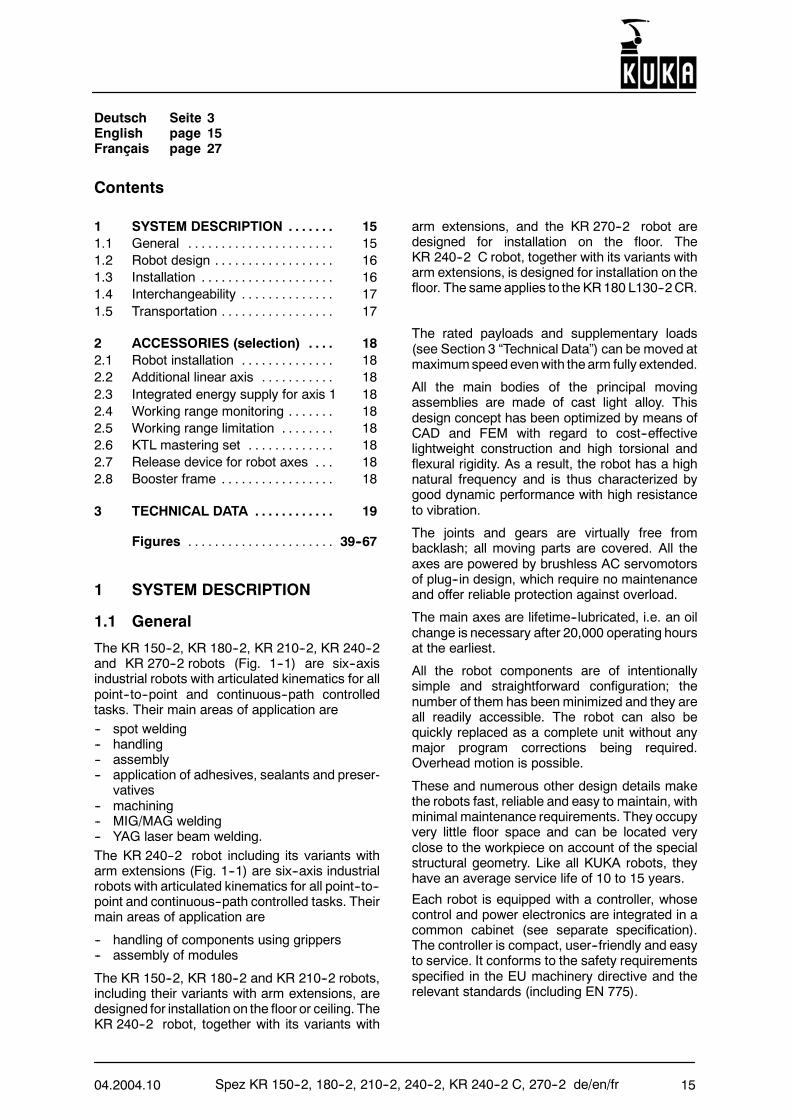
Deutsch Seite 3English page 15Français page 27
Contents
1 SYSTEM DESCRIPTION 15. . . . . . .1.1 General 15. . . . . . . . . . . . . . . . . . . . . .1.2 Robot design 16. . . . . . . . . . . . . . . . . .1.3 Installation 16. . . . . . . . . . . . . . . . . . . .1.4 Interchangeability 17. . . . . . . . . . . . . .1.5 Transportation 17. . . . . . . . . . . . . . . . .
2 ACCESSORIES (selection) 18. . . .2.1 Robot installation 18. . . . . . . . . . . . . .2.2 Additional linear axis 18. . . . . . . . . . .2.3 Integrated energy supply for axis 1 182.4 Working range monitoring 18. . . . . . .2.5 Working range limitation 18. . . . . . . .2.6 KTL mastering set 18. . . . . . . . . . . . .2.7 Release device for robot axes 18. . .2.8 Booster frame 18. . . . . . . . . . . . . . . . .
3 TECHNICAL DATA 19. . . . . . . . . . . .
Figures 39--67. . . . . . . . . . . . . . . . . . . . . .
1 SYSTEM DESCRIPTION
1.1 General
The KR 150--2, KR 180--2, KR 210--2, KR 240--2and KR 270--2 robots (Fig. 1--1) are six--axisindustrial robots with articulated kinematics for allpoint--to--point and continuous--path controlledtasks. Their main areas of application are-- spot welding-- handling-- assembly-- application of adhesives, sealants and preser-
vatives-- machining-- MIG/MAG welding-- YAG laser beam welding.The KR 240--2 robot including its variants witharm extensions (Fig. 1--1) are six--axis industrialrobots with articulated kinematics for all point--to--point and continuous--path controlled tasks. Theirmain areas of application are
-- handling of components using grippers-- assembly of modules
The KR 150--2, KR 180--2 and KR 210--2 robots,including their variants with arm extensions, aredesigned for installation on the floor or ceiling. TheKR 240--2 robot, together with its variants with
arm extensions, and the KR 270--2 robot aredesigned for installation on the floor. TheKR 240--2 C robot, together with its variants witharm extensions, is designed for installation on thefloor. The same applies to the KR180 L130--2CR.
The rated payloads and supplementary loads(see Section 3 “Technical Data”) can be moved atmaximumspeedevenwith thearm fully extended.
All the main bodies of the principal movingassemblies are made of cast light alloy. Thisdesign concept has been optimized by means ofCAD and FEM with regard to cost--effectivelightweight construction and high torsional andflexural rigidity. As a result, the robot has a highnatural frequency and is thus characterized bygood dynamic performance with high resistanceto vibration.
The joints and gears are virtually free frombacklash; all moving parts are covered. All theaxes are powered by brushless AC servomotorsof plug--in design, which require no maintenanceand offer reliable protection against overload.
The main axes are lifetime--lubricated, i.e. an oilchange is necessary after 20,000 operating hoursat the earliest.
All the robot components are of intentionallysimple and straightforward configuration; thenumber of them has beenminimized and they areall readily accessible. The robot can also bequickly replaced as a complete unit without anymajor program corrections being required.Overhead motion is possible.
These and numerous other design details makethe robots fast, reliable and easy to maintain, withminimal maintenance requirements. They occupyvery little floor space and can be located veryclose to the workpiece on account of the specialstructural geometry. Like all KUKA robots, theyhave an average service life of 10 to 15 years.
Each robot is equipped with a controller, whosecontrol and power electronics are integrated in acommon cabinet (see separate specification).The controller is compact, user--friendly and easyto service. It conforms to the safety requirementsspecified in the EU machinery directive and therelevant standards (including EN 775).
Spez KR 150--2, 180--2, 210--2, 240--2, KR 240--2 C, 270--2 de/en/fr 04.2004.1016
The connecting cables between the robot and thecontroller contain all the relevant energy supplyand signal lines. The cable connections on therobot are of theplug--in type, as tooare theenergyand fluid supply lines for the operation of endeffectors (“integrated energy supply for axis 1”accessory). These lines are permanently installedinside main axis 1 of the robot and can be routedalong the downstream axes to the end effectorwith the aid of system interfaces if required.
1.2 Robot design
The robot consists of a fixed base frame, onwhichthe rotating column turns about a vertical axistogether with the link arm, arm and wrist (Fig.1--1).
The wrist (Fig. 1--2) is provided with a mountingflange for the attachment of end effectors (e.g.grippers, welding tools).
The possible movements of the robot axes aredepicted in Figure 1--3.
Thepayloadand thedeadweight of thearticulatedcomponents are statically compensated to a largeextent by a closed counterbalancing system,which assists axis 2. By retrofitting a conversionkit (accessory), the effect can be varieddepending on the payload and supplementaryload of the particular application and on theinstallation position of the robot.
The positions of the main and wrist axes (A 1 toA 3 and A 4 to A 6) are sensed by means of acyclically absolute position sensing systemfeaturing a resolver for each axis.
Each axis is driven by a transistor--controlled,low--inertia AC servomotor. The brake andresolver are space--efficiently integrated into themotor unit.
Theworking rangeof the robot is limited bymeansof software limit switches on all axes. Theworkingranges of axes 1, 2, 3 and 5 are mechanicallylimited by end stops with a buffer function.
Mechanical stops for the application--specificlimitation of the respective working ranges of axes1 to 3 are available as the “working rangelimitation” accessory.
The in--line wrist variant “F” is available foroperating conditions involving greater mechanicaland thermal stress. It is more extensively sealedand is fitted with corrosion--resistant components.Shorter maintenance intervals are required tomaintain the higher stress rating.
With “F” variant robots, the arm is pressurized. Itis operated with an internal pressure of 0.1 bar.
In cleanroom environments, the variant KR 180L130--2 CR with in--line wrist IW 130 CR is used.
This variant has been extensively modified toachieve a substantially reduced level of particleemission compared with the standard version.The robot is additionally fitted with corrosion--resistant components.
1.3 Installation
There are several possible methods of installingthe robot:
-- Variant 1
This variant is available with bedplates,locating pins, anchors and bolts as the“mounting base kit” accessory.The robot is mounted together with fourbedplates (Fig. 1--4) on the prepared shopfloor. Its position of installation is fixed bymeans of two locating pins, enabling it to beexchanged in a repeatable manner. The robotis fastened to the bedplates with eight bolts.Each of the bedplates is fastened to the shopfloor with three anchor bolts before the robot ismounted on them.
-- Variant 2
This variant is available with locating pins andbolts as the “machine base mounting kit”accessory.The robot is placed on a prepared steelconstruction and fastenedwith eight bolts (Fig.1--5). Its position of installation is fixed bymeans of two locating pins, enabling it to beexchanged in a repeatable manner.
-- Variant 3
This variant is available with a booster frame,locating pins, chemical anchors and bolts asthe “booster frame” accessory.The booster frame is fastened to the preparedshop floor by means of 16 chemical anchors(Fig. 1--6). The robot is fastened to the boosterframe with eight bolts. Its position ofinstallation is fixed by means of two locatingpins, enabling it to be exchanged in arepeatable manner.
IMPORTANT with regard to variants 1 and 3:When preparing the foundation, the pertinentconstruction specifications regarding thegrade of concrete (≥ B 25 according to DIN1045:1988 or C20/25 according to DIN EN206--1:2001/DIN 1045--2:2001) and the loadbearing capacity of the ground must beobserved. It must be ensured that the surfaceof the foundation is level and sufficientlysmooth.The insertion of thechemical anchorsmustbecarried out with great care to ensure that theforces occurring during operation (Fig. 1--7)
04.2004.10 Spez KR 150--2, 180--2, 210--2, 240--2, KR 240--2 C, 270--2 de/en/fr 17
will be safely transmitted to the ground.Figure 1--7 could also be used as a basis formore extensive static investigations.
1.4 Interchangeability
In manufacturing systems with a large number ofrobots, it is important for the robots to be readilyinterchangeable. This is ensured by
-- the reproducibility of the synchronizationpositions marked by the manufacturer on allaxes, the so--calledmechanical zero positions,and
-- the computer--aided zero adjustmentprocedure,
and is additionally supported by
-- off--line programming, which canbe carried outin advance and remotely from the robot, and
-- the reproducible installation of the robot.
After service and maintenance work (on the wristand motors, for example), it is necessary toestablish coincidence between the electrical andmechanical zero positions (calibration) of therobot. A gage cartridge is mounted by themanufacturer on each robot axis for this purpose.
These gage cartridges are set by themanufacturer when the robot is calibrated prior toshipment. The fact that measurements on eachaxis are always made using the same cartridgemeans that maximum accuracy is achieved bothwhen first calibrating themechanical zero positionand when subsequently relocating it.
The position of the mechanical probe fitted in thegage cartridge can be displayed by screwing anelectronic probe (KTLmastering set), available asan accessory, onto the cartridge. The positionsensing system is automatically set to electricalzero when the probe passes the reference notchduring the adjustment procedure.
The robot can resume operation once the zeroadjustment has been carried out on all axes.
The procedures describedmake it possible for theprograms, once defined, to be transferred at anytime to any other robot of the same type.
1.5 Transportation
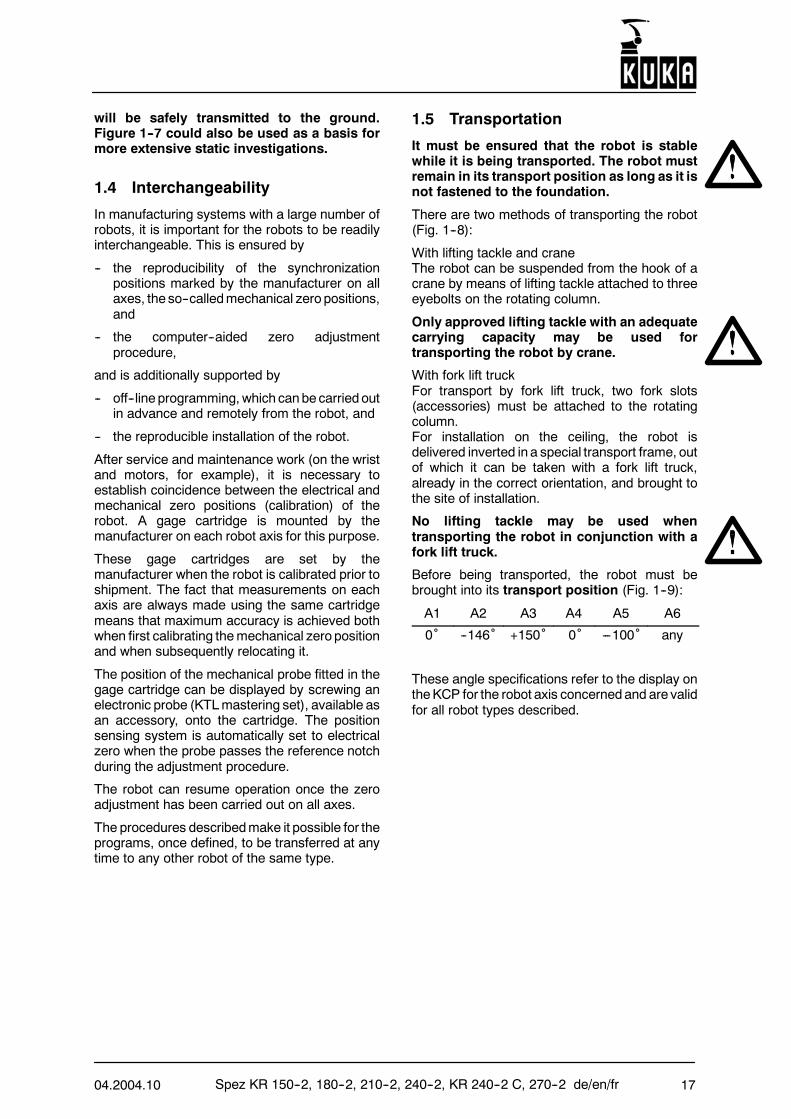
It must be ensured that the robot is stablewhile it is being transported. The robot mustremain in its transport position as long as it isnot fastened to the foundation.
There are two methods of transporting the robot(Fig. 1--8):
With lifting tackle and craneThe robot can be suspended from the hook of acrane by means of lifting tackle attached to threeeyebolts on the rotating column.
Only approved lifting tackle with an adequatecarrying capacity may be used fortransporting the robot by crane.
With fork lift truckFor transport by fork lift truck, two fork slots(accessories) must be attached to the rotatingcolumn.For installation on the ceiling, the robot isdelivered inverted in a special transport frame, outof which it can be taken with a fork lift truck,already in the correct orientation, and brought tothe site of installation.
No lifting tackle may be used whentransporting the robot in conjunction with afork lift truck.
Before being transported, the robot must bebrought into its transport position (Fig. 1--9):
A1 A2 A3 A4 A5 A6
0˚ --146˚ +150˚ 0˚ ---100˚ any
These angle specifications refer to the display ontheKCP for the robot axis concernedand are validfor all robot types described.
Spez KR 150--2, 180--2, 210--2, 240--2, KR 240--2 C, 270--2 de/en/fr 04.2004.1018
Dimensions for packing the robot in a container:
Robot type L(mm)
B(mm)
H(mm)
KR 150--2 1723 1184 1671KR 150 L130--2 1923 1184 1671KR 150 L110--2 2122 1184 1671KR 180--2 1723 1184 1671KR 180 L150--2 1923 1184 1671KR 180 L130--2 2122 1184 1671KR 210--2 1723 1184 1671KR 210 L180--2 1923 1184 1671KR 210 L150--2 2122 1184 1671KR 240--2 1723 1184 1671KR 240 L210--2 1923 1184 1671KR 240 L180--2 2122 1184 1671KR 240--2 C 1723 1184 1671KR 240 L210--2 C 1723 1184 1671KR 240 L180--2 C 1723 1184 1671KR 270--2 1723 1184 1671
2 ACCESSORIES (selection)
2.1 Robot installation
There are three variants available for installing therobot:-- with mounting base kit (Fig. 1--4)-- with machine base mounting kit (Fig. 1--5)-- with booster frame (Fig. 1--6).
See Section 1.3 for a description.
2.2 Additional linear axis
With the aid of a linear unit as an additionaltraversing axis, based on the KL 1500 series (Fig.2--1), the robot can be moved translationally. Theaxis is freely programmable and can be installedon the floor or the ceiling.
2.3 Integrated energy supply foraxis 1
Various energy supply systems are available,including systems for the applications “handling”and “spot welding”. In the area of axis 1, thenecessary supply lines run inside the robot fromthe plug connection panel to an interface on therotating column (Fig. 2--2).
From here, additional supply lines can be routedexternally along the link arm and arm to anappropriate interface on the end effector. Thiseliminates the need for a space--consumingsupply boom.
2.4 Working range monitoring
Standard version
Axes 1 to 3 canbeequippedwith positionswitchesor proximity switches and slotted rings to whichadjustable cams are attached. This allows theposition of the robot to be continuouslymonitored.
Up to three sectors of themovement range canbemonitored on axis 1, up to two sectors on axis 2and one sector on axis 3.
If axes 2 and 3 are equipped with working rangemonitoring, an “energy supply system for axis 1”with an additional control cable is required.
2.5 Working range limitation
The movement ranges of axes 1 to 3 can belimited by means of additional mechanical stopsas required by the application.
2.6 KTL mastering set
The zero adjustment operation, which is neces-sary for all axes, can be performed with the aid ofthe electronic probe belonging to a KTLmasteringset (Fig. 2--3 and 3--16). This probe provides aparticularly fast and simple means of measure-ment and allows automatic, computer--aidedadjustment. It should be included in the order forthe robot.
2.7 Release device for robot axes
This device can be used to move the main axesand wrist axes of the robot mechanically via thedrive motors after a malfunction. It should only beused in emergencies (e.g. for freeing personnel).
2.8 Booster frame
The booster frame (Fig. 2--4) is a steel structureon which the robot can be mounted (see alsoSection 1.3 “Installation, Variant 3”).
It is available in heights from 150 mm to 1950mmin 150 mm intervals.
04.2004.10 Spez KR 150--2, 180--2, 210--2, 240--2, KR 240--2 C, 270--2 de/en/fr 19
3 TECHNICAL DATATypes KR 150--2, KR 240--2
KR 150 L130--2, KR 240 L210--2,KR 150 L110--2 KR 240 L180--2KR 180--2, KR 240--2 CKR 180 L150--2, KR 240 L210--2 CKR 180 L130--2 KR 240 L180--2 CKR 210--2, KR 270--2KR 210 L180--2KR 210 L150--2
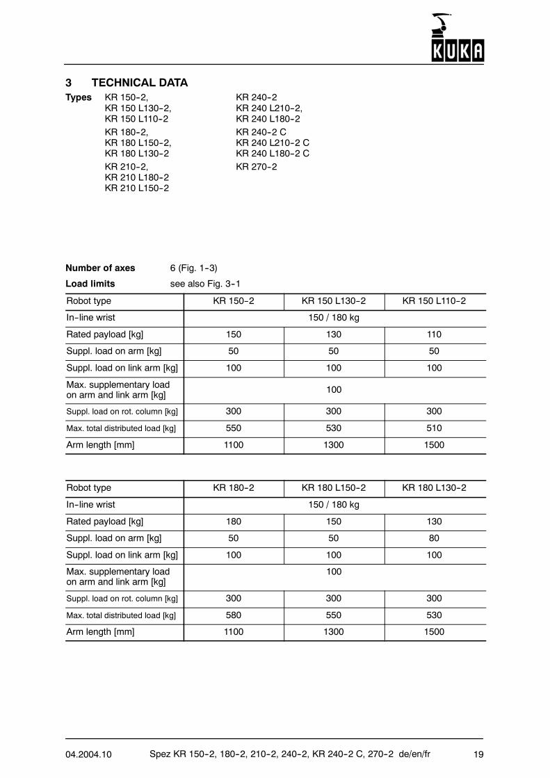
Number of axes 6 (Fig. 1--3)
Load limits see also Fig. 3--1
Robot type KR 150--2 KR 150 L130--2 KR 150 L110--2
In--line wrist 150 / 180 kg
Rated payload [kg] 150 130 110
Suppl. load on arm [kg] 50 50 50
Suppl. load on link arm [kg] 100 100 100
Max. supplementary loadon arm and link arm [kg] 100
Suppl. load on rot. column [kg] 300 300 300
Max. total distributed load [kg] 550 530 510
Arm length [mm] 1100 1300 1500
Robot type KR 180--2 KR 180 L150--2 KR 180 L130--2
In--line wrist 150 / 180 kg
Rated payload [kg] 180 150 130
Suppl. load on arm [kg] 50 50 80
Suppl. load on link arm [kg] 100 100 100
Max. supplementary loadon arm and link arm [kg]
100
Suppl. load on rot. column [kg] 300 300 300
Max. total distributed load [kg] 580 550 530
Arm length [mm] 1100 1300 1500
Spez KR 150--2, 180--2, 210--2, 240--2, KR 240--2 C, 270--2 de/en/fr 04.2004.1020
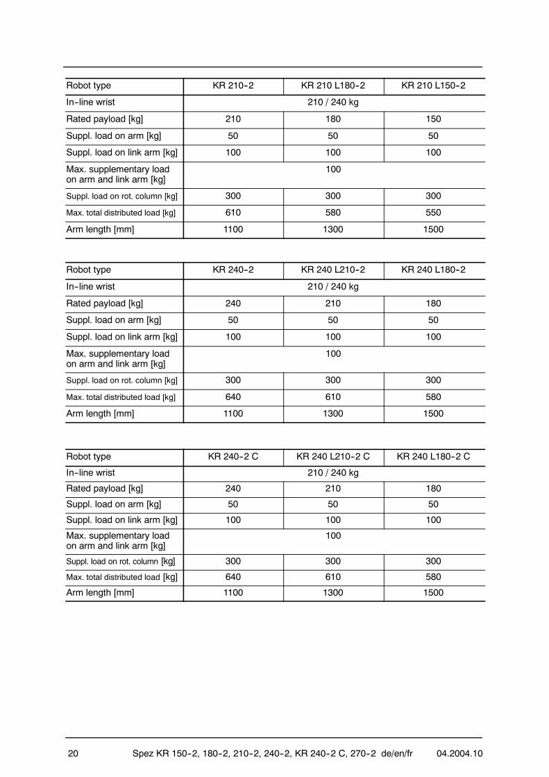
Robot type KR 210--2 KR 210 L180--2 KR 210 L150--2
In--line wrist 210 / 240 kg
Rated payload [kg] 210 180 150
Suppl. load on arm [kg] 50 50 50
Suppl. load on link arm [kg] 100 100 100
Max. supplementary loadon arm and link arm [kg]
100
Suppl. load on rot. column [kg] 300 300 300
Max. total distributed load [kg] 610 580 550
Arm length [mm] 1100 1300 1500
Robot type KR 240--2 KR 240 L210--2 KR 240 L180--2
In--line wrist 210 / 240 kg
Rated payload [kg] 240 210 180
Suppl. load on arm [kg] 50 50 50
Suppl. load on link arm [kg] 100 100 100
Max. supplementary loadon arm and link arm [kg]
100
Suppl. load on rot. column [kg] 300 300 300
Max. total distributed load [kg] 640 610 580
Arm length [mm] 1100 1300 1500
Robot type KR 240--2 C KR 240 L210--2 C KR 240 L180--2 C
In--line wrist 210 / 240 kg
Rated payload [kg] 240 210 180
Suppl. load on arm [kg] 50 50 50
Suppl. load on link arm [kg] 100 100 100
Max. supplementary loadon arm and link arm [kg]
100
Suppl. load on rot. column [kg] 300 300 300
Max. total distributed load [kg] 640 610 580
Arm length [mm] 1100 1300 1500
04.2004.10 Spez KR 150--2, 180--2, 210--2, 240--2, KR 240--2 C, 270--2 de/en/fr 21
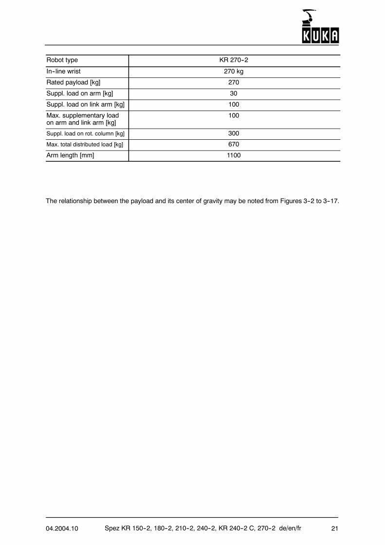
Robot type KR 270--2
In--line wrist 270 kg
Rated payload [kg] 270
Suppl. load on arm [kg] 30
Suppl. load on link arm [kg] 100
Max. supplementary loadon arm and link arm [kg]
100
Suppl. load on rot. column [kg] 300
Max. total distributed load [kg] 670
Arm length [mm] 1100
The relationship between the payload and its center of gravity may be noted from Figures 3--2 to 3--17.
Spez KR 150--2, 180--2, 210--2, 240--2, KR 240--2 C, 270--2 de/en/fr 04.2004.1022
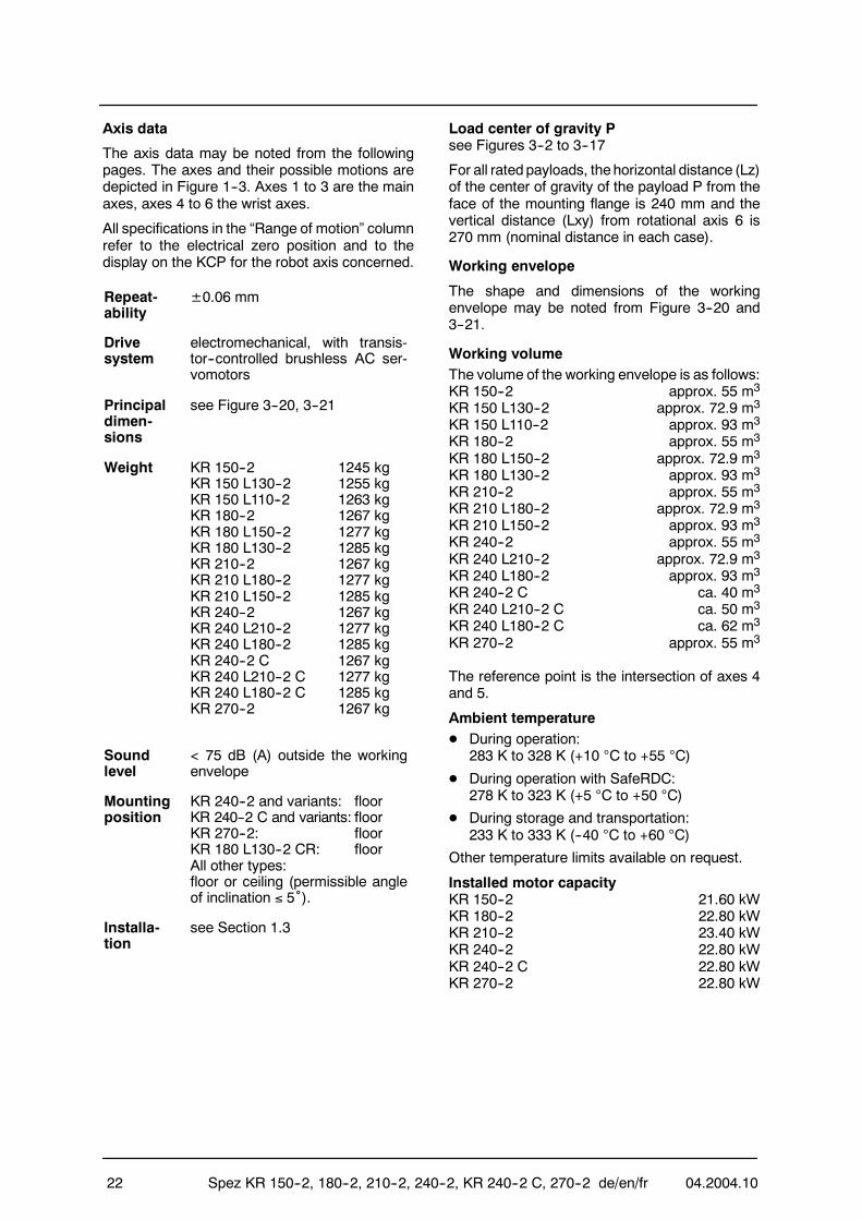
Axis data
The axis data may be noted from the followingpages. The axes and their possible motions aredepicted in Figure 1--3. Axes 1 to 3 are the mainaxes, axes 4 to 6 the wrist axes.
All specifications in the “Range of motion” columnrefer to the electrical zero position and to thedisplay on the KCP for the robot axis concerned.
Repeat-ability
±0.06 mm
Drivesystem
electromechanical, with transis-tor--controlled brushless AC ser-vomotors
Principaldimen-sions
see Figure 3--20, 3--21
Weight KR 150--2 1245 kgKR 150 L130--2 1255 kgKR 150 L110--2 1263 kgKR 180--2 1267 kgKR 180 L150--2 1277 kgKR 180 L130--2 1285 kgKR 210--2 1267 kgKR 210 L180--2 1277 kgKR 210 L150--2 1285 kgKR 240--2 1267 kgKR 240 L210--2 1277 kgKR 240 L180--2 1285 kgKR 240--2 C 1267 kgKR 240 L210--2 C 1277 kgKR 240 L180--2 C 1285 kgKR 270--2 1267 kg
Soundlevel
< 75 dB (A) outside the workingenvelope
Mountingposition
KR 240--2 and variants: floorKR 240--2 C and variants: floorKR 270--2: floorKR 180 L130--2 CR: floorAll other types:floor or ceiling (permissible angleof inclination ≤ 5˚).
Installa-tion
see Section 1.3
Load center of gravity Psee Figures 3--2 to 3--17
For all ratedpayloads, thehorizontal distance (Lz)of the center of gravity of the payload P from theface of the mounting flange is 240 mm and thevertical distance (Lxy) from rotational axis 6 is270 mm (nominal distance in each case).
Working envelope
The shape and dimensions of the workingenvelope may be noted from Figure 3--20 and3--21.
Working volumeThe volume of the working envelope is as follows:KR 150--2 approx. 55 m3
KR 150 L130--2 approx. 72.9 m3
KR 150 L110--2 approx. 93 m3
KR 180--2 approx. 55 m3
KR 180 L150--2 approx. 72.9 m3
KR 180 L130--2 approx. 93 m3
KR 210--2 approx. 55 m3
KR 210 L180--2 approx. 72.9 m3
KR 210 L150--2 approx. 93 m3
KR 240--2 approx. 55 m3
KR 240 L210--2 approx. 72.9 m3
KR 240 L180--2 approx. 93 m3
KR 240--2 C ca. 40 m3
KR 240 L210--2 C ca. 50 m3
KR 240 L180--2 C ca. 62 m3
KR 270--2 approx. 55 m3
The reference point is the intersection of axes 4and 5.
Ambient temperatureD During operation:
283 K to 328 K (+10 °C to +55 °C)
D During operation with SafeRDC:278 K to 323 K (+5 °C to +50 °C)
D During storage and transportation:233 K to 333 K (--40 °C to +60 °C)
Other temperature limits available on request.
Installed motor capacityKR 150--2 21.60 kWKR 180--2 22.80 kWKR 210--2 23.40 kWKR 240--2 22.80 kWKR 240--2 C 22.80 kWKR 270--2 22.80 kW
04.2004.10 Spez KR 150--2, 180--2, 210--2, 240--2, KR 240--2 C, 270--2 de/en/fr 23
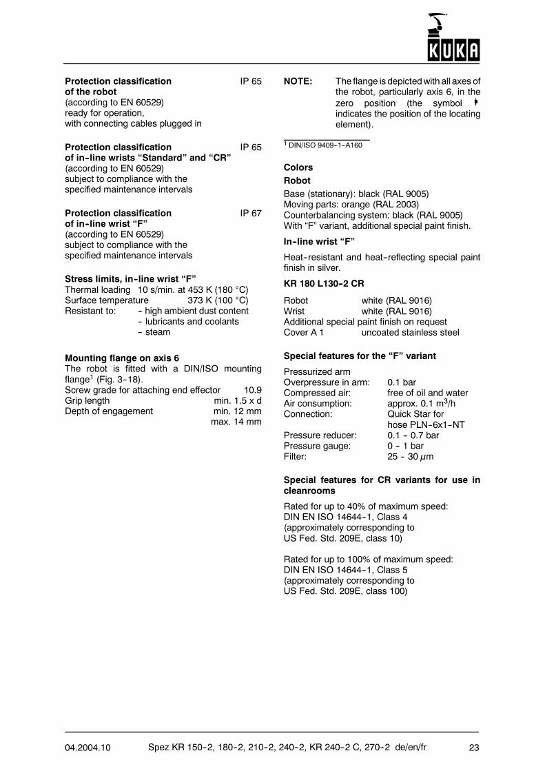
Protection classification IP 65of the robot(according to EN 60529)ready for operation,with connecting cables plugged in
Protection classification IP 65of in--line wrists “Standard” and “CR”(according to EN 60529)subject to compliance with thespecified maintenance intervals
Protection classification IP 67of in--line wrist “F”(according to EN 60529)subject to compliance with thespecified maintenance intervals
Stress limits, in--line wrist “F”Thermal loading 10 s/min. at 453 K (180 °C)Surface temperature 373 K (100 °C)Resistant to: -- high ambient dust content
-- lubricants and coolants-- steam
Mounting flange on axis 6The robot is fitted with a DIN/ISO mountingflange1 (Fig. 3--18).Screw grade for attaching end effector 10.9Grip length min. 1.5 x dDepth of engagement min. 12 mm
max. 14 mm
NOTE: The flange is depictedwith all axes ofthe robot, particularly axis 6, in thezero position (the symbolindicates the position of the locatingelement).
1 DIN/ISO 9409--1--A160
ColorsRobotBase (stationary): black (RAL 9005)Moving parts: orange (RAL 2003)Counterbalancing system: black (RAL 9005)With “F” variant, additional special paint finish.
In--line wrist “F”
Heat--resistant and heat--reflecting special paintfinish in silver.
KR 180 L130--2 CR
Robot white (RAL 9016)Wrist white (RAL 9016)Additional special paint finish on requestCover A 1 uncoated stainless steel
Special features for the “F” variant
Pressurized armOverpressure in arm: 0.1 barCompressed air: free of oil and waterAir consumption: approx. 0.1 m3/hConnection: Quick Star for
hose PLN--6x1--NTPressure reducer: 0.1 -- 0.7 barPressure gauge: 0 -- 1 barFilter: 25 -- 30 µm
Special features for CR variants for use incleanrooms
Rated for up to 40% of maximum speed:DIN EN ISO 14644--1, Class 4(approximately corresponding toUS Fed. Std. 209E, class 10)
Rated for up to 100% of maximum speed:DIN EN ISO 14644--1, Class 5(approximately corresponding toUS Fed. Std. 209E, class 100)
Spez KR 150--2, 180--2, 210--2, 240--2, KR 240--2 C, 270--2 de/en/fr 04.2004.1024
Axis data
KR 150--2,KR 150 L130--2,KR 150 L110--2D In--line wrist, rated payload 150/130/110 kg
Axis Range of motionsoftware--limited
Speed with rated payload
150 kg 130 kg 110 kg
1 ±185˚ 110 ˚/s 105 ˚/s 105 ˚/s
2 +0˚to
--146˚110 ˚/s 110 ˚/s 110 ˚/s
3 +155˚to
--119˚100 ˚/s 95 ˚/s 93 ˚/s
4 ±350˚ 170 ˚/s 170 ˚/s 170 ˚/s
5 ±125˚ 170 ˚/s 170 ˚/s 170 ˚/s
6 ±350˚ 238 ˚/s 238 ˚/s 238 ˚/s
KR 180--2,KR 180 L150--2,KR 180 L130--2D In--line wrist, rated payload 180/150/130 kg
Axis Range of motionsoftware--limited
Speed with rated payload
180 kg 150 kg 130 kg
1 ±185˚ 95 ˚/s 95 ˚/s 95 ˚/s
2 +0˚to
--146˚95 ˚/s 95 ˚/s 95 ˚/s
3 +155˚to
--119˚90 ˚/s 87 ˚/s 83 ˚/s
4 ±350˚ 162 ˚/s 168 ˚/s 171 ˚/s
5 ±125˚ 164 ˚/s 168 ˚/s 170 ˚/s
6 ±350˚ 229 ˚/s 235 ˚/s 238 ˚/s
04.2004.10 Spez KR 150--2, 180--2, 210--2, 240--2, KR 240--2 C, 270--2 de/en/fr 25
KR 210--2,KR 210 L180--2,KR 210 L150--2D In--line wrist, rated payload 210/180/150 kg
Axis Range of motionsoftware--limited
Speed with rated payload
210 kg 180 kg 150 kg
1 ±185˚ 86 ˚/s 86 ˚/s 86 ˚/s
2 +0˚to
--146˚84 ˚/s 84 ˚/s 84 ˚/s
3 +155˚to
--119˚84 ˚/s 84 ˚/s 81 ˚/s
4 ±350˚ 100 ˚/s 100 ˚/s 100 ˚/s
5 ±125˚ 110 ˚/s 110 ˚/s 110 ˚/s
6 ±350˚ 184 ˚/s 184 ˚/s 184 ˚/s
KR 240--2,KR 240 L210--2,KR 240 L180--2D In--line wrist, rated payload 240/210/180 kg
Axis Range of motionsoftware--limited
Speed with rated payload
240 kg 210 kg 180 kg
1 ±185˚ 86 ˚/s 86 ˚/s 82 ˚/s
2 +0˚to
--146˚80 ˚/s 78 ˚/s 78 ˚/s
3 +155˚to
--119˚79 ˚/s 74 ˚/s 76 ˚/s
4 ±350˚ 100 ˚/s 100 ˚/s 100 ˚/s
5 ±125˚ 110 ˚/s 110 ˚/s 110 ˚/s
6 ±350˚ 184 ˚/s 184 ˚/s 184 ˚/s
Spez KR 150--2, 180--2, 210--2, 240--2, KR 240--2 C, 270--2 de/en/fr 04.2004.1026
KR 270--2D In--line wrist, rated payload 270 kg
Axis Range of motionsoftware--limited
Speed with rated payload
270 kg
1 ±185˚ 85 ˚/s
2 +0˚bis
--146˚79 ˚/s
3 +155˚bis
--119˚77 ˚/s
4 ±350˚ 100 ˚/s
5 ±125˚ 100 ˚/s
6 ±350˚ 156 ˚/s
04.2004.10 Spez KR 150--2, 180--2, 210--2, 240--2, KR 240--2 C, 270--2 de/en/fr 27
Deutsch Seite 3English page 15Français page 27
Table des matières1 DESCRIPTION DU SYSTEME 27. .1.1 Généralités 27. . . . . . . . . . . . . . . . . . .1.2 Ensemble mécanique du robot 28. .1.3 Mise en place 28. . . . . . . . . . . . . . . . .1.4 Echange 29. . . . . . . . . . . . . . . . . . . . . .1.5 Transport 29. . . . . . . . . . . . . . . . . . . . .
2 ACCESSOIRES (sélection) 30. . . .2.1 Fixation du robot 30. . . . . . . . . . . . . . .2.2 Axe linéaire supplémentaire 30. . . . .2.3 Alimentation en énergie intégrée
pour l’axe 1 30. . . . . . . . . . . . . . . . . . .2.4 Surveillance de l’enveloppe
d’évolution 30. . . . . . . . . . . . . . . . . . . .2.5 Limitation de l’enveloppe
d’évolution 30. . . . . . . . . . . . . . . . . . . .2.6 Set de réglage KTL 30. . . . . . . . . . . .2.7 Dispositif de libération des axes
de robot 30. . . . . . . . . . . . . . . . . . . . . .2.8 Plate--forme 30. . . . . . . . . . . . . . . . . . .
3 CARACTERISTIQUESTECHNIQUES 31. . . . . . . . . . . . . . . .
Figures 39--67. . . . . . . . . . . . . . . . . . . . . .
1 DESCRIPTION DU SYSTEME
1.1 GénéralitésLes robots KR 150--2, KR 180--2, KR 210--2, KR240--2 et KR 270--2 (fig. 1--1) sont des robotsindustriels à six axes à cinématique articuléepouvant être mis enœuvre pour toutes les tâchesavec positionnement en continu (contournage) etpoint par point. Les principaux domaines de miseen œuvre sont:-- soudage par points-- manutention-- montage-- application de colles, produits de conservation
et d’étanchéification-- usinage-- soudage MIG/MAG-- coupage au rayon laser YAG.Le robot KR 240--2 et ses variantes avecprolongation du bras sont des robots industriels àsix axes à cinématique articulée pouvant être misen œuvre pour toutes les tâches avecpositionnement en continu (contournage) et pointpar point. Les principaux domaines de mise enœuvre sont:-- Manipulation de pièces avec un préhenseur-- Montage de sous--ensemble
Les robots KR 150--2, KR 180--2 et KR 210--2 etleurs variantes avec prolongation du bras peuvent
être montés au sol ou au plafond. Le robotKR 240--2 et ses variantes avec prolongation dubras et le robot KR 270--2 peuvent êtremontés ausol. De même, le KR 180 L130--2 CR. Le robotKR 240--2Cet ses variantes avec prolongation dubras peuvent être montés au plafont.Les charges nominales et les chargessupplémentaires (voir paragraphe 3 “Caractéri-stiques techniques”) peuvent également êtredéplacées à la vitessemaxi et avec la portéemaxidu bras.Tous les carters des sous--ensembles principauxmobiles sont en fonte d’alliage léger. Ce concepta encore été optimisé avec la CFAOet laméthodedes éléments finis quant aux critères suivants:construction rentable légère et résistanceimportante à la torsion ainsi qu’à la flexion. Il enrésulte donc une fréquence propre trèsimportante du robot caractérisé ainsi par unexcellent comportement dynamique avec unehaute résistance aux vibrations.Les articulations, les joints et les mécanismes detransmission sont caractérisés par unmouvement pratiquement sans jeu. Toutes lespièces mobiles sont recouvertes. Tous lesmoteurs d’entraînement sont des servomoteursAC sans balais enfichables ne nécessitantaucune maintenance et protégés d’une manièrefiable contre la surcharge.Les axesmajeurs sont lubrifiés à vie, c.à.d. qu’unevidange d’huile est nécessaire après 20 000heures de service au plus tôt.Tous les composants du robot ont été conçussciemment d’une manière simple et claire. Leurnombrea étéminimisé. Tous les composants sontaisément accessibles. Le robot pourra égalementêtre échangé rapidement en tant qu’unitécomplète sans que ceci suppose une correctionimportante du programme. Un basculement enarrière est également possible.Ce point ainsi que de nombreux autres détailsconstructifs confèrent au robot une fiabilité et unerapidité très importantes ainsi qu’une très grandefacilité de maintenance. L’encombrementnécessité est très faible. Vue la géométrieparticulière des superstructures, les robotspeuvent être montés à proximité de la pièce. Al’instar des robots industriels éprouvés des autresséries KUKA, la durée de vie moyenne s’élève à10--15 ans.Chaque robot est doté d’une commande dont lesélectroniques de commande et de puissance sontintégrées dans une armoire de commandecommune (voir spécification spéciale). Cette
Spez KR 150--2, 180--2, 210--2, 240--2, KR 240--2 C, 270--2 de/en/fr 04.2004.1028
commande a un encombrement réduit, présenteune grande simplicité de maintenance et autoriseune conduite aisée du système. Le niveau desécurité répond à la DirectiveMachines CE et auxnormes en vigueur (entre autres DIN EN 775).Les câbles de liaison entre le robot et lacommande contiennent toutes les lignesd’alimentation et de signaux nécessaires. Ellessont enfichables sur le robot. Ceci s’appliqueégalement aux câbles d’énergie et des fluidespour l’exploitation des outils (accessoire“Alimentation en énergie intégrée pour l’axe 1”).Dans la zone de l’axe majeur 1, ces câbles sontfixés et posés à l’intérieur du robot. En cas debesoin, les câbles d’énergie et des fluides pour lefonctionnement des outils peuvent être posésjusqu’à l’outil le long des axes secondaires entravaillant avec le système d’interfaces.
1.2 Ensemble mécanique du robotLe robot est formé d’une embase fixe sur laquelletourne autour d’un axe vertical le “bâti de rotation”qui supporte l’épaule, le bras et le poignet (fig.1--1).La bride de fixation dupoignet (fig. 1--2) permet demonter les outils (par exemple préhenseurs,appareils de soudage).La figure 1--3 représente les mouvementspossibles des axes du robot.La charge utile et le poids mort des composantsarticulés sont compensés statiquement dans lamesure du possible par un système d’équilibragefermé en soi. Ce système assiste l’axe 2. Avec lemontage du kit d’adaptation (disponible enoption)l’efficacité pourra être variée en fonction de lachargeutile et de la charge supplémentaire du casd’application en question et en fonction de laposition de montage du robot.La mesure de la position pour les axes majeurs etles axes mineurs (A 1 à A 3 et A 4 à A 6) se ferapar un système de mesure cycliquement absolude la position avec un résolveur pour chaque axe.L’entraînement se fera par des servomoteurs ACcommandés par transistors et à faible inertie. Lefrein et le résolveur sont intégrés d’une façon peuencombrante dans les unités actionneurs.L’enveloppe d’évolution du robot est limitée danstous les axes par des fins de course logiciels.L’enveloppe d’évolution des axes 1, 2, 3 et 5 estlimitée mécaniquement par des butées avecfonction tampon.Des butées mécaniques pour une limitation del’enveloppe d’évolution en fonction du casd’application sont disponibles comme accessoire“Limitation de l’enveloppe d’évolution” pour lesaxes 1 à 3.
En cas de sollicitations thermiques ou mécani-ques plus importantes, le poignet en ligne du type“F” est disponible. Ce poignet est caractérisé parunemeilleure étanchéité et des pièces résistant àla corrosion. Pour conserver la fiabilité, il faut parcontre respecter les intervalles de maintenanceplus courts.Dans le cas des robots du type “F”, le bras estsous pression. Il fonctionne avec une pressioninterne de 0,1 bar.Dans un environnement de chambre stérile, lavariante KR 180 L130--2 CR avec PL 130 CR estutilisée. D’importantes modifications ont permisde réduire sensiblement l’émission de particulespar rapport à la version standard. En outre, lerobot est équipédepièces résistant à la corrosion.
1.3 Mise en placeIl existe plusieurs possibilités pour la mise enplace du robot:
-- Variante 1Cette variante est fournie avec des plaques defondation, des pieds de centrage, deschevilleset des vis comme accessoire “Kit de fixationaux fondations”.Le robot est posé avec quatre plaques defondation sur le sol du hall préparé (fig. 1--4).Sa position de montage est définie par deuxpieds de centrage pour permettre ainsi unerépétabilité de l’échange. La fixation du robotse fait avec huit vis sur les plaques defondation.Avant lamiseen placedu robot, les plaques defondation sont fixées au sol du hall avecrespectivement trois vis à chevilles.
-- Variante 2Cette variante avec des pieds de centrage etdes vis est fournie comme accessoire “Kit defixation à l’embase de la machine”.Le robot est posé sur une construction enacierpréparée pour être vissé avec huit vis (fig.1--5). Sa position de montage est définie pardeux pieds de centrage pour permettre ainsiune répétabilité de l’échange.
-- Variante 3Cette variante est fournie avec uneplate--forme, des pieds de centrage, deschevilles chimiques et des vis commeaccessoire “Plate--forme”.Cette plate--forme est fixée avec 16 chevilleschimiques sur le sol du hall préparé (fig. 1--6).La fixation du robot se fait avec huit vis sur laplate--forme. Sa position de montage estdéfinie par deux pieds de centrage pourpermettre ainsi une répétabilité de l’échange.
04.2004.10 Spez KR 150--2, 180--2, 210--2, 240--2, KR 240--2 C, 270--2 de/en/fr 29
ATTENTION.-- Dans le cas de la variante 1 et 3,il faudra, lors de la préparation desfondations, respecter les prescriptions deconstruction en vigueur en ce qui concerne laqualité du béton (≥ B 25 selon norme DIN1045:1988 ou C20/25 selon norme DIN EN206--1:2001/DIN 1045--2:2001) et la portancedu sol. Lors de l’exécution des fondations,veiller à obtenir une surface de niveausuffisamment plane et lisse.La fixation des chevilles chimiques doit sefaire avec une minutie extrème pour que lesforces engendrées lors de l’exploitation durobot (fig. 1--7) soient fiablement introduitesdans le sol. La figure 1--7 peut également êtreutilisée pour des études statiques pluspoussées.
1.4 Echange
Dans le cas des installations de productioncomprenant un certain nombre de robots, il fautgarantir que l’échange des robots entre eux nepose aucun problème. Ceci est obtenu de lamanière suivante:
-- reproductibilité des positions de synchroni--sation repérées à l’usine pour tous les axes,c.à.d. de la position zéro mécanique, et
-- calibration du point zéro assistée parordinateur.
L’échange est en outre favorisé par:
-- une programmation autonome ou offlinepouvant non seulement se faire auparavantmais encore à distance du robot, et
-- la mise en place reproductible du robot.
Les travaux de maintenance et de service après-vente (entre autres poignet et moteurs)nécessitent que l’on obtienne la position zéro tantmécanique qu’électrique (calibration) du robot. Acette fin, les cartouches de mesure sont prévuesdépart usine pour chaque axe du robot.
Le réglage des cartouches de mesure fait partiedes opérations de mesure qui précèdent lalivraison du robot. Comme on mesure toujoursavec lamême cartouche à chaque axe, on obtientune précision maximale non seulement lors de lapremière mesure mais encore lors desrecherches ultérieures de la position zéromécanique.
Pour signaler la position du palpeur dans lacartouche, on visse comme accessoire unmesureur électronique (set de réglage KTL) sur lacartouche. Lorsqu’onpasseainsi par l’encochederéférence lors du réglage, le système de mesureest automatiquement réglé sur une positionélectrique zéro.
Le robot peut être remis en service après avoirréglé le point zéro pour tous les axes.
Grâce à ces opérations, les programmesdéterminés ainsi peuvent à tout moment êtretransférés à n’importe quel autre robot du mêmetype.
1.5 TransportLa stabilité doit être prise en compte lors dutransport du robot. Tant que le robot n’est pasfixé aux fondations, il doit rester en positionde transport.
Le robot peut être transporté de deux manières(fig. 1--8):
Avec dispositif de transport et une grueLe robot est transporté avec le dispositif detransport accroché aux trois vis à anneau du bâtide rotation, aux crochets de la grue.Pour le transport du robot avec une grue, onne peut travailler qu’avec des dispositifs delevageet dechargeautoriséspour unechargesuffisante.
Avec chariot élévateur à fourchesPour le transport avec le chariot élévateur àfourches, il faudra monter sur le bâti de rotationdeux poches (option) destinées à recevoir lesfourches du chariot.Pour la fixation au plafond, le robot est livréaccroché dans un dispositif de transport spécial.Il peut être retiré de ce dispositif avec un chariotélévateur à fourches déjà en position de montagecorrecte et transporté.
Pour le transport du robot avec un chariot élé-vateur, il est interdit de travailler avec un dis-positif de levage ou de charge.
Avant chaque transport, le robot doit être amenéen position de transport (fig. 1--9):
A1 A2 A3 A4 A5 A6
0˚ --146˚ +150˚ 0˚ ---100˚ quel--conque
Les angles se rapportent à l’affichage au KCP del’axe en question du robot et sont valable pourtous les types.
Spez KR 150--2, 180--2, 210--2, 240--2, KR 240--2 C, 270--2 de/en/fr 04.2004.1030
Cotes pour l’emballage du robot dans leconteneur:
Type de robot Lo(mm)
La(mm)
H(mm)
KR 150--2 1723 1184 1671KR 150 L130--2 1923 1184 1671KR 150 L110--2 2122 1184 1671KR 180--2 1723 1184 1671KR 180 L150--2 1923 1184 1671KR 180 L130--2 2122 1184 1671KR 210--2 1723 1184 1671KR 210 L180--2 1923 1184 1671KR 210 L150--2 2122 1184 1671KR 240--2 1723 1184 1671KR 240 L210--2 1923 1184 1671KR 240 L180--2 2122 1184 1671KR 240--2 C 1723 1184 1671KR 240 L210--2 C 1723 1184 1671KR 240 L180--2 C 1723 1184 1671KR 270--2 1723 1184 1671
2 ACCESSOIRES (sélection)
2.1 Fixation du robot
La fixation du robot peut se faire selon troisvariantes:-- avec kit de fixation aux fondations (fig. 1--4)-- avec kit de fixation à l’embase de la machine
(fig. 1--5)-- avec plate--forme (fig. 1--6).
Description voir paragraphe 1.3.
2.2 Axe linéaire supplémentaire
A l’aide d’une unité linéaire comme axe dedéplacement supplémentaire sur la base de lasérie KL 1500 (fig. 2--1), le robot peut faire l’objetd’une translation, programmable, au sol ou auplafond.
2.3 Alimentation en énergieintégrée pour l’axe 1
Diverses alimentations en énergie sontdisponibles, entre autres pour les applications“Manutention” et “Soudage par points”. Lescâbles et les flexibles correspondants sont posés,dans la zone de l’axe 1, dans le robot, du panneaude raccordement jusqu’à une interface au bâti derotation (fig. 2--2).
Des câbles et flexibles supplémentaires peuventêtre ensuite posés à l’extérieur sur l’épaule et lebras jusqu’à une interface correspondante del’outil. La potence d’alimentation très encom-brante est donc inutile.
2.4 Surveillance de l’envelopped’évolution
Version standardLes axes 1à3peuvent recevoir des fins de courseou des détecteurs de proximité et des baguesrainurées sur lesquelles sont fixées des camesréglables afin d’obtenir une surveillancepermanente de la position du robot.
Dans le cas de l’axe 1, on peut contrôler aumaximum trois secteurs, dans le cas de l’axe 2 aumaximum 2 secteurs et dans le cas de l’axe 3 aumaximum un secteur des plages de déplacementen question.
Si les axes 2 ou 3 sont dotés d’une surveillancedel’enveloppe d’évolution, il faut une “Alimentationen énergie pour l’axe 1” avec un câble decommande supplémentaire.
2.5 Limitation de l’envelopped’évolution
Les plages de déplacement des axes 1 à 3peuvent être limitées en fonction du casd’application avec des butées mécaniquessupplémentaires.
2.6 Set de réglage KTL
Afin de réaliser un réglage du point zéro néces-saire pour tous les axes, on peut utiliser unmesureur électronique (fig. 2--3 et 3--19) qui faitpartie du set de réglage KTL. Ce mesureurélectronique autorise un mesurage particulière-ment simple et rapide ainsi qu’un réglageautoma-tique assisté par ordinateur. Il devrait être com-mandé avec le robot.
2.7 Dispositif de libération des axesde robot
Ce dispositif permet, après une panne, dedéplacer mécaniquement le robot via les moteursd’entrainement des axes majeurs et les moteursd’entraînement des axes du poignet. Ce dispositifne devrait être utilisé qu’en cas d’urgence (par ex.pour dégager des personnes).
2.8 Plate--forme
La plate--forme (fig. 2--4) est une construction enacier permettant la fixation du robot (voir aussiparagraphe 1.3 “Mise en place, variante 3”).
Hauteurs disponibles: de 150mmà1950mm, parpas de 150 mm.
04.2004.10 Spez KR 150--2, 180--2, 210--2, 240--2, KR 240--2 C, 270--2 de/en/fr 31
3 CARACTERISTIQUES TECHNIQUES
Types KR 150--2, KR 240--2KR 150 L130--2, KR 240 L210--2,KR 150 L110--2 KR 240 L180--2KR 180--2, KR 240--2 CKR 180 L150--2, KR 240 L210--2 CKR 180 L130--2 KR 240 L180--2 CKR 210--2, KR 270--2KR 210 L180--2KR 210 L150--2
Nombre d’axes 6 (fig. 1--3)Charge admissible Cf. également fig. 3--1
Type de robot KR 150--2 KR 150 L130--2 KR 150 L110--2
Poignet en ligne 150 / 180 kg
Charge nominaleadmissible [kg] 150 130 110
Charge suppl. bras [kg] 50 50 50
Charge suppl. épaule [kg] 100 100 100
Charge suppl. maxibras et épaule [kg] 100
Charge supplémentairebâti de rotation [kg] 300 300 300
Charge maxi totale [kg] 550 530 510
Longueur du bras [mm] 1100 1300 1500
Type de robot KR 180--2 KR 180 L150--2 KR 180 L130--2
Poignet en ligne 150 / 180 kg
Charge nominaleadmissible [kg]
180 150 130
Charge suppl. bras [kg] 50 50 80
Charge suppl. épaule [kg] 100 100 100
Charge suppl. maxibras et épaule [kg]
100
Charge supplémentairebâti de rotation [kg]
300 300 300
Charge maxi totale [kg] 580 550 530
Longueur du bras [mm] 1100 1300 1500
Spez KR 150--2, 180--2, 210--2, 240--2, KR 240--2 C, 270--2 de/en/fr 04.2004.1032
Type de robot KR 210--2 KR 210 L180--2 KR 210 L150--2
Poignet en ligne 210 / 240 kg
Charge nominaleadmissible [kg]
210 180 150
Charge suppl. bras [kg] 50 50 50
Charge suppl. épaule [kg] 100 100 100
Charge suppl. maxibras et épaule [kg]
100
Charge supplémentairebâti de rotation [kg]
300 300 300
Charge maxi totale [kg] 610 580 550
Longueur du bras [mm] 1100 1300 1500
Type de robot KR 240--2 KR 240 L210--2 K240 L150--2
Poignet en ligne 210 / 240 kg
Charge nominaleadmissible [kg]
210 180 150
Charge suppl. bras [kg] 50 50 50
Charge suppl. épaule [kg] 100 100 100
Charge suppl. maxibras et épaule [kg]
100
Charge supplémentairebâti de rotation [kg]
300 300 300
Charge maxi totale [kg] 610 580 550
Longueur du bras [mm] 1100 1300 1500
Type de robot KR 240--2 C KR 240 L210--2 C KR 240 L180--2 C
Poignet en ligne 210 / 240 kg
Charge nominaleadmissible [kg]
240 210 180
Charge suppl. bras [kg] 50 50 50
Charge suppl. épaule [kg] 100 100 100
Charge suppl. maxibras et épaule [kg]
100
Charge supplémentairebâti de rotation [kg]
300 300 300
Charge maxi totale [kg] 640 610 580
Longueur du bras [mm] 1100 1300 1500
04.2004.10 Spez KR 150--2, 180--2, 210--2, 240--2, KR 240--2 C, 270--2 de/en/fr 33
Type de robot KR 270--2
Poignet en ligne 270 kg
Charge nominaleadmissible [kg]
270
Charge suppl. bras [kg] 30
Charge suppl. épaule [kg] 100
Charge suppl. maxibras et épaule [kg]
100
Charge supplémentairebâti de rotation [kg]
300
Charge maxi totale [kg] 670
Longueur du bras [mm] 1100
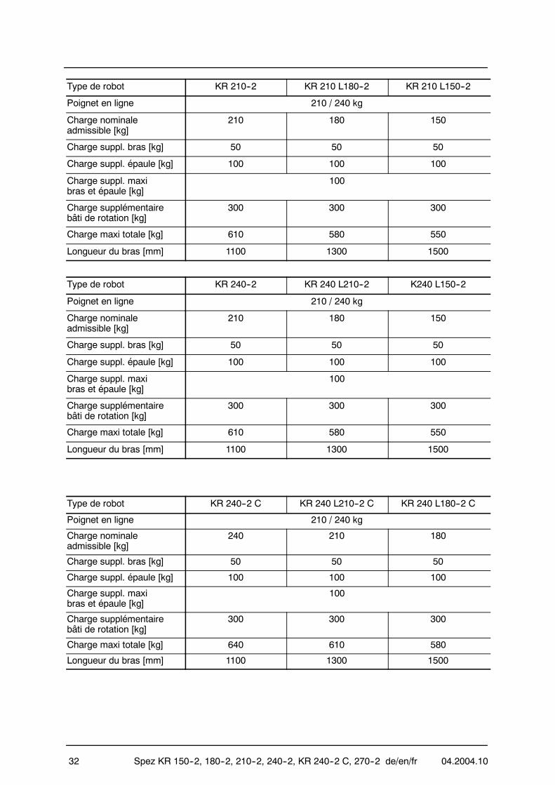
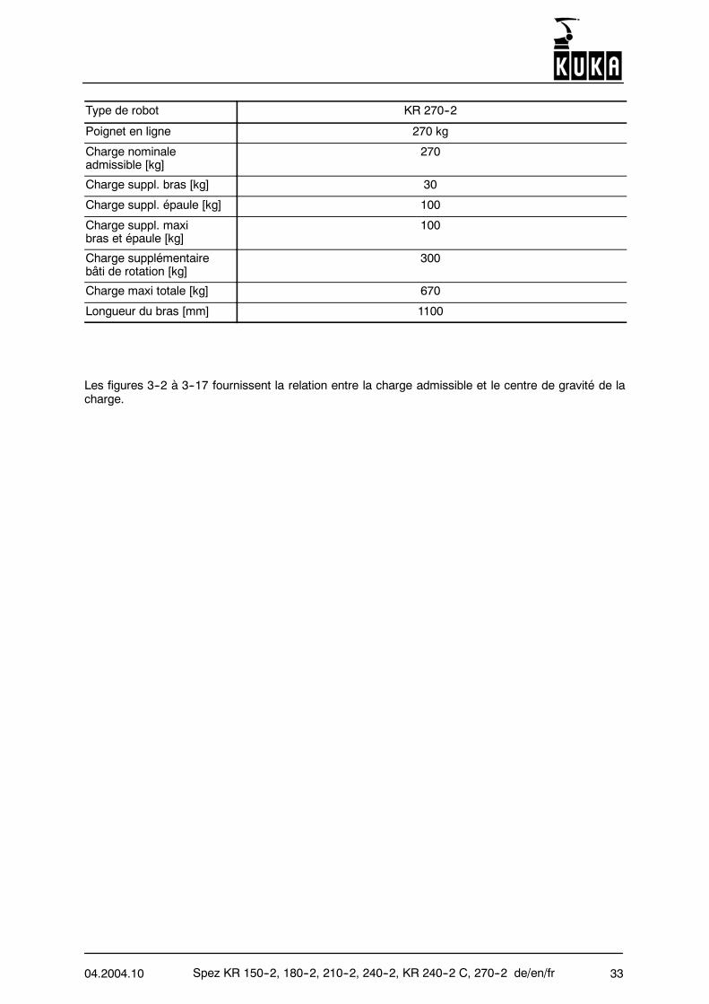
Les figures 3--2 à 3--17 fournissent la relation entre la charge admissible et le centre de gravité de lacharge.
Spez KR 150--2, 180--2, 210--2, 240--2, KR 240--2 C, 270--2 de/en/fr 04.2004.1034
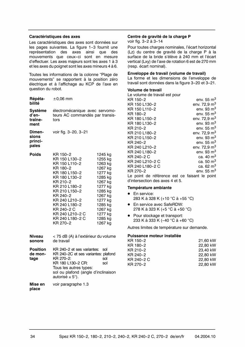
Caractéristiques des axesLes caractéristiques des axes sont données surles pages suivantes. La figure 1--3 fournit unereprésentation des axes ainsi que desmouvements que ceux--ci sont en mesured’effectuer. Les axes majeurs sont les axes 1 à 3et les axes du poignet sont les axesmineurs 4 à 6.
Toutes les informations de la colonne “Plage demouvements” se rapportent à la position zéroélectrique et à l’affichage au KCP de l’axe enquestion du robot.
Répéta-bilité
±0,06 mm
Systèmed’en-traîne-ment
électromécanique avec servomo-teurs AC commandés par transis-tors
Dimen-sionsprinci-pales
voir fig. 3--20, 3--21
Poids KR 150--2 1245 kgKR 150 L130--2 1255 kgKR 150 L110--2 1263 kgKR 180--2 1267 kgKR 180 L150--2 1277 kgKR 180 L130--2 1285 kgKR 210--2 1267 kgKR 210 L180--2 1277 kgKR 210 L150--2 1285 kgKR 240--2 1267 kgKR 240 L210--2 1277 kgKR 240 L180--2 1285 kgKR 240--2 C 1267 kgKR 240 L210--2 C 1277 kgKR 240 L180--2 C 1285 kgKR 270--2 1267 kg
Niveausonore
< 75 dB (A) à l’extérieur du volumede travail
Positionde mon-tage
KR 240--2 et ses variantes: solKR 240--2C et ses variantes: plafondKR 270--2: solKR 180 L130--2 CR: solTous les autres types:sol ou plafond (angle d’inclinaisonautorisé ≤ 5°).
Mise enplace
voir paragraphe 1.3
Centre de gravité de la charge Pvoir fig. 3--2 à 3--14Pour toutes charges nominales, l’écart horizontal(Lz) du centre de gravité de la charge P à lasurface de la bride s’élève à 240 mm et l’écartvertical (Lxy) de l’axe de rotation 6 est de 270mm(resp. écart nominal).
Enveloppe de travail (volume de travail)La forme et les dimensions de l’enveloppe detravail sont données dans la figure 3--20 et 3--21.
Volume de travailLe volume de travail est pourKR 150--2 env. 55 m3
KR 150 L130--2 env. 72,9 m3
KR 150 L110--2 env. 93 m3
KR 180--2 env. 55 m3
KR 180 L150--2 env. 72,9 m3
KR 180 L130--2 env. 93 m3
KR 210--2 env. 55 m3
KR 210 L180--2 env. 72,9 m3
KR 210 L150--2 env. 93 m3
KR 240--2 env. 55 m3
KR 240 L210--2 env. 72,9 m3
KR 240 L180--2 env. 93 m3
KR 240--2 C ca. 40 m3
KR 240 L210--2 C ca. 50 m3
KR 240 L180--2 C ca. 62 m3
KR 270--2 env. 55 m3
Le point de référence est ce faisant le pointd’intersection des axes 4 et 5.
Température ambianteD En service:
283 K à 328 K (+10 °C à +55 °C)D En service avec SafeRDW:
278 K à 323 K (+5 °C à +50 °C)
D Pour stockage et transport:233 K à 333 K (--40 °C à +60 °C)
Autres limites de température sur demande.
Puissance moteur installéeKR 150--2 21,60 kWKR 180--2 22,80 kWKR 210--2 23,40 kWKR 240--2 22,80 kWKR 240--2 C 22,80 kWKR 270--2 22,80 kW
04.2004.10 Spez KR 150--2, 180--2, 210--2, 240--2, KR 240--2 C, 270--2 de/en/fr 35
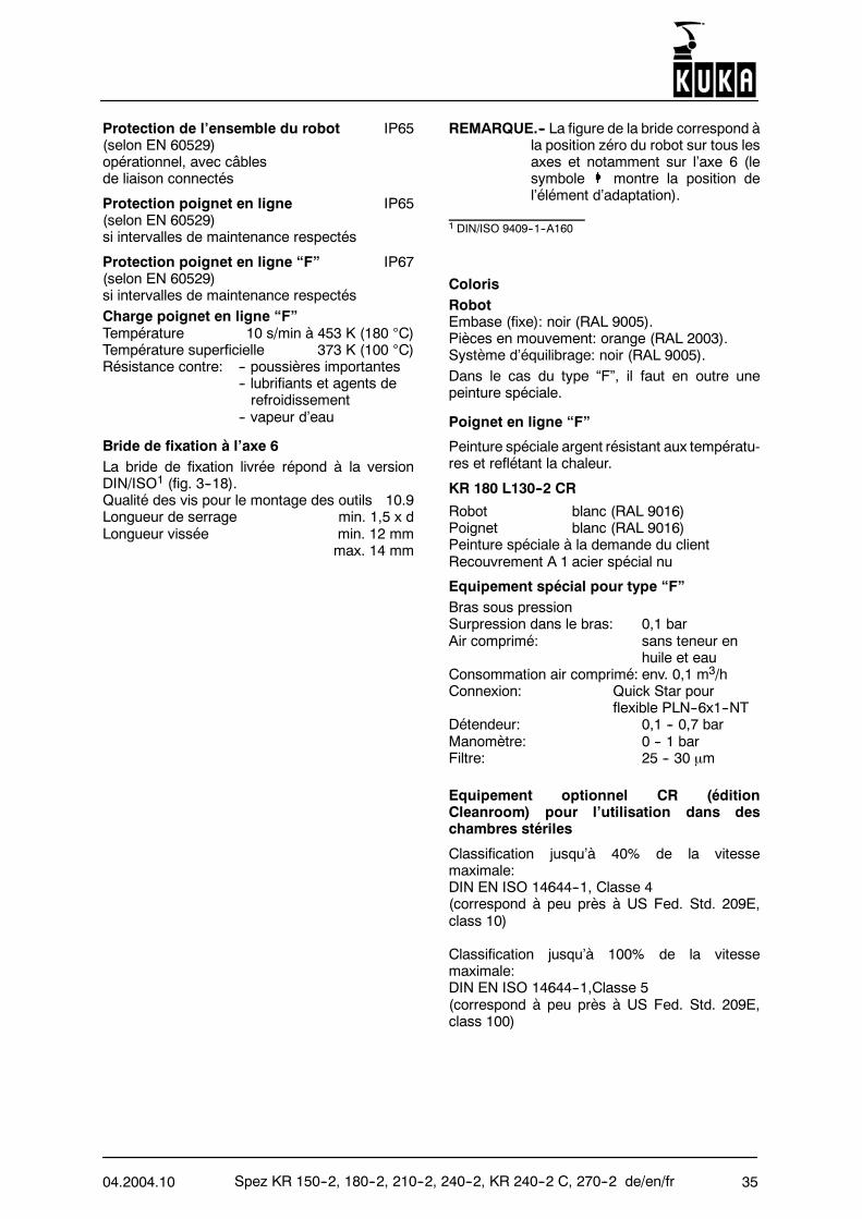
Protection de l’ensemble du robot IP65(selon EN 60529)opérationnel, avec câblesde liaison connectés
Protection poignet en ligne IP65(selon EN 60529)si intervalles de maintenance respectés
Protection poignet en ligne “F” IP67(selon EN 60529)si intervalles de maintenance respectésCharge poignet en ligne “F”Température 10 s/min à 453 K (180 °C)Température superficielle 373 K (100 °C)Résistance contre: -- poussières importantes
-- lubrifiants et agents derefroidissement
-- vapeur d’eau
Bride de fixation à l’axe 6La bride de fixation livrée répond à la versionDIN/ISO1 (fig. 3--18).Qualité des vis pour le montage des outils 10.9Longueur de serrage min. 1,5 x dLongueur vissée min. 12 mm
max. 14 mm
REMARQUE.-- La figure de la bride correspond àla position zéro du robot sur tous lesaxes et notamment sur l’axe 6 (lesymbole montre la position del’élément d’adaptation).
1 DIN/ISO 9409--1--A160
ColorisRobotEmbase (fixe): noir (RAL 9005).Pièces en mouvement: orange (RAL 2003).Système d’équilibrage: noir (RAL 9005).Dans le cas du type “F”, il faut en outre unepeinture spéciale.
Poignet en ligne “F”
Peinture spéciale argent résistant aux températu-res et reflétant la chaleur.
KR 180 L130--2 CR
Robot blanc (RAL 9016)Poignet blanc (RAL 9016)Peinture spéciale à la demande du clientRecouvrement A 1 acier spécial nu
Equipement spécial pour type “F”Bras sous pressionSurpression dans le bras: 0,1 barAir comprimé: sans teneur en
huile et eauConsommation air comprimé: env. 0,1 m3/hConnexion: Quick Star pour
flexible PLN--6x1--NTDétendeur: 0,1 -- 0,7 barManomètre: 0 -- 1 barFiltre: 25 -- 30 µm
Equipement optionnel CR (éditionCleanroom) pour l’utilisation dans deschambres stériles
Classification jusqu’à 40% de la vitessemaximale:DIN EN ISO 14644--1, Classe 4(correspond à peu près à US Fed. Std. 209E,class 10)
Classification jusqu’à 100% de la vitessemaximale:DIN EN ISO 14644--1,Classe 5(correspond à peu près à US Fed. Std. 209E,class 100)
Spez KR 150--2, 180--2, 210--2, 240--2, KR 240--2 C, 270--2 de/en/fr 04.2004.1036
Caractéristiques des axes
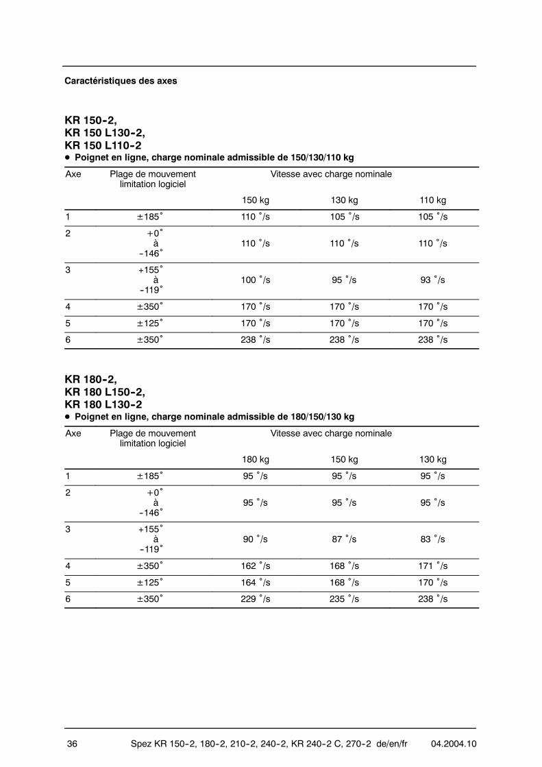
KR 150--2,KR 150 L130--2,KR 150 L110--2D Poignet en ligne, charge nominale admissible de 150/130/110 kg
Axe Plage de mouvementlimitation logiciel
Vitesse avec charge nominale
150 kg 130 kg 110 kg
1 ±185˚ 110 ˚/s 105 ˚/s 105 ˚/s
2 +0˚à
--146˚110 ˚/s 110 ˚/s 110 ˚/s
3 +155˚à
--119˚100 ˚/s 95 ˚/s 93 ˚/s
4 ±350˚ 170 ˚/s 170 ˚/s 170 ˚/s
5 ±125˚ 170 ˚/s 170 ˚/s 170 ˚/s
6 ±350˚ 238 ˚/s 238 ˚/s 238 ˚/s
KR 180--2,KR 180 L150--2,KR 180 L130--2D Poignet en ligne, charge nominale admissible de 180/150/130 kg
Axe Plage de mouvementlimitation logiciel
Vitesse avec charge nominale
180 kg 150 kg 130 kg
1 ±185˚ 95 ˚/s 95 ˚/s 95 ˚/s
2 +0˚à
--146˚95 ˚/s 95 ˚/s 95 ˚/s
3 +155˚à
--119˚90 ˚/s 87 ˚/s 83 ˚/s
4 ±350˚ 162 ˚/s 168 ˚/s 171 ˚/s
5 ±125˚ 164 ˚/s 168 ˚/s 170 ˚/s
6 ±350˚ 229 ˚/s 235 ˚/s 238 ˚/s
04.2004.10 Spez KR 150--2, 180--2, 210--2, 240--2, KR 240--2 C, 270--2 de/en/fr 37
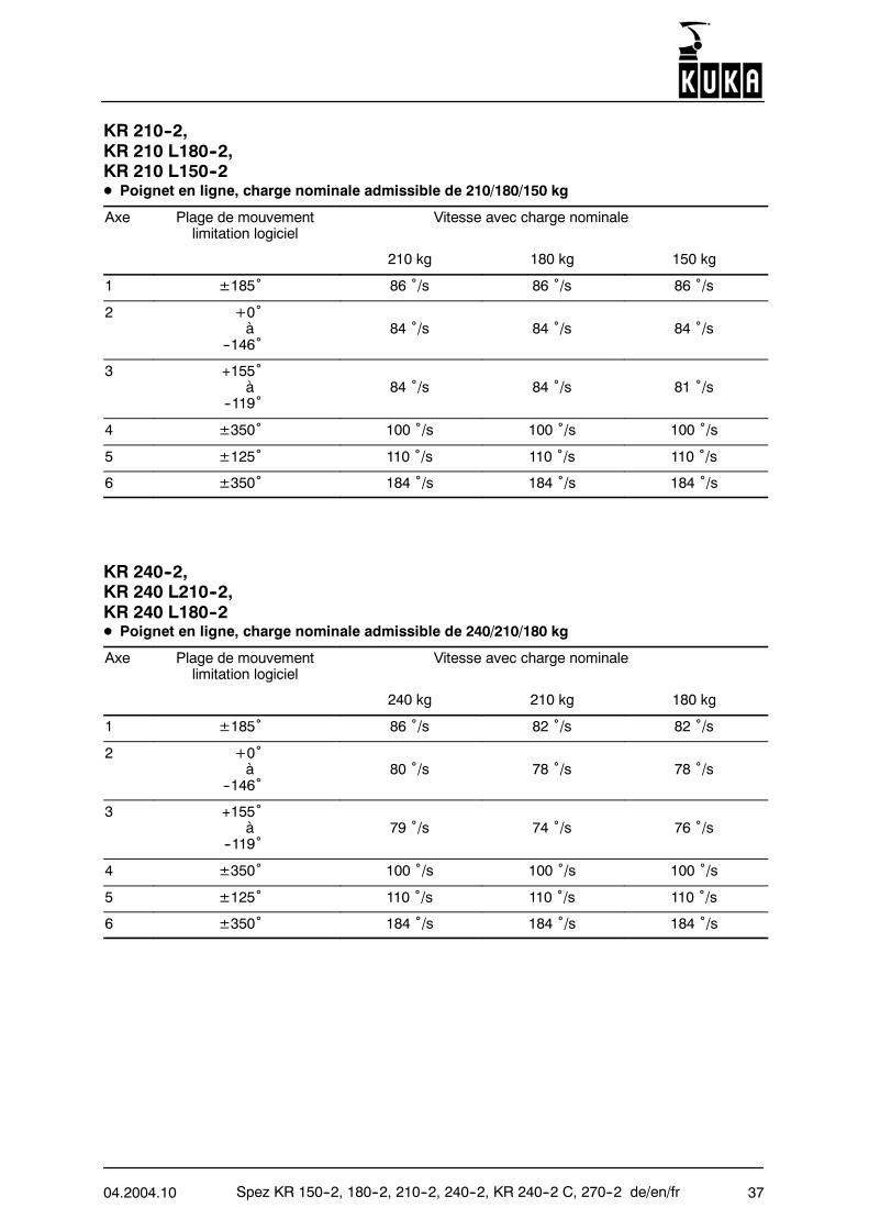
KR 210--2,KR 210 L180--2,KR 210 L150--2D Poignet en ligne, charge nominale admissible de 210/180/150 kg
Axe Plage de mouvementlimitation logiciel
Vitesse avec charge nominale
210 kg 180 kg 150 kg
1 ±185˚ 86 ˚/s 86 ˚/s 86 ˚/s
2 +0˚à
--146˚84 ˚/s 84 ˚/s 84 ˚/s
3 +155˚à
--119˚84 ˚/s 84 ˚/s 81 ˚/s
4 ±350˚ 100 ˚/s 100 ˚/s 100 ˚/s
5 ±125˚ 110 ˚/s 110 ˚/s 110 ˚/s
6 ±350˚ 184 ˚/s 184 ˚/s 184 ˚/s
KR 240--2,KR 240 L210--2,KR 240 L180--2D Poignet en ligne, charge nominale admissible de 240/210/180 kg
Axe Plage de mouvementlimitation logiciel
Vitesse avec charge nominale
240 kg 210 kg 180 kg
1 ±185˚ 86 ˚/s 82 ˚/s 82 ˚/s
2 +0˚à
--146˚80 ˚/s 78 ˚/s 78 ˚/s
3 +155˚à
--119˚79 ˚/s 74 ˚/s 76 ˚/s
4 ±350˚ 100 ˚/s 100 ˚/s 100 ˚/s
5 ±125˚ 110 ˚/s 110 ˚/s 110 ˚/s
6 ±350˚ 184 ˚/s 184 ˚/s 184 ˚/s
Spez KR 150--2, 180--2, 210--2, 240--2, KR 240--2 C, 270--2 de/en/fr 04.2004.1038
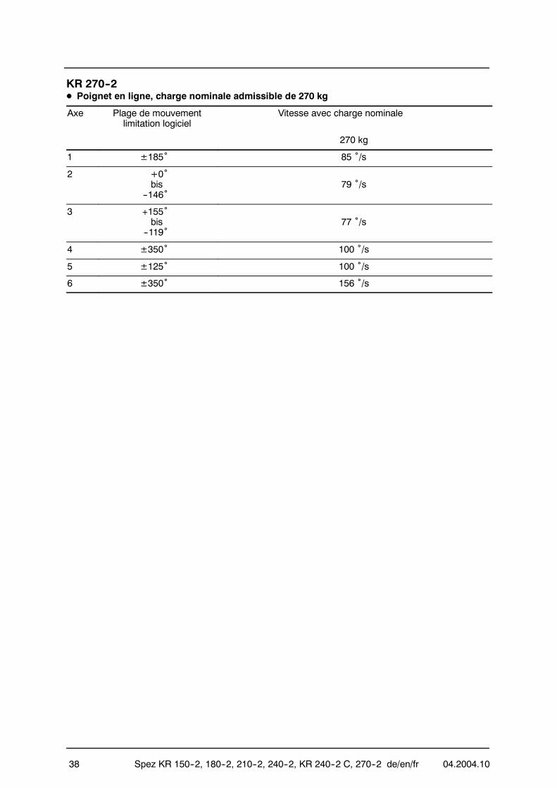
KR 270--2D Poignet en ligne, charge nominale admissible de 270 kg
Axe Plage de mouvementlimitation logiciel
Vitesse avec charge nominale
270 kg
1 ±185˚ 85 ˚/s
2 +0˚bis
--146˚79 ˚/s
3 +155˚bis
--119˚77 ˚/s
4 ±350˚ 100 ˚/s
5 ±125˚ 100 ˚/s
6 ±350˚ 156 ˚/s
04.2004.10 Spez KR 150--2, 180--2, 210--2, 240--2, KR 240--2 C, 270--2 de/en/fr 39
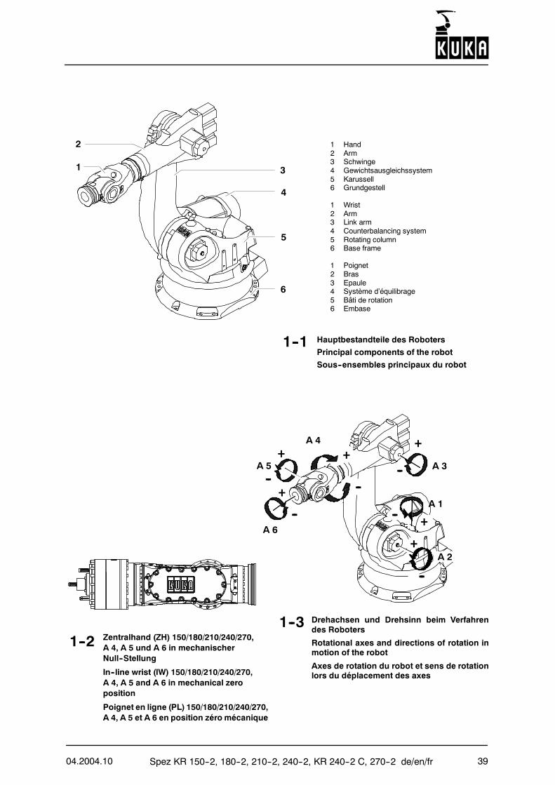
1--2 Zentralhand (ZH) 150/180/210/240/270,A 4, A 5 und A 6 in mechanischerNull--Stellung
In--line wrist (IW) 150/180/210/240/270,A 4, A 5 and A 6 in mechanical zeroposition
Poignet en ligne (PL) 150/180/210/240/270,A 4, A 5 et A 6 en position zéro mécanique
1 Hand2 Arm3 Schwinge4 Gewichtsausgleichssystem5 Karussell6 Grundgestell
1 Wrist2 Arm3 Link arm4 Counterbalancing system5 Rotating column6 Base frame
1 Poignet2 Bras3 Epaule4 Système d’équilibrage5 Bâti de rotation6 Embase
Hauptbestandteile des Roboters
Principal components of the robot
Sous--ensembles principaux du robot
1--3 Drehachsen und Drehsinn beim Verfahrendes Roboters
Rotational axes and directions of rotation inmotion of the robot
Axes de rotation du robot et sens de rotationlors du déplacement des axes
1--1
A 3
A 4
A 5
A 6
+
--
--
+
A 2
A 1
--+
--
+
-- +
+
1
2
4
5
6
--
3
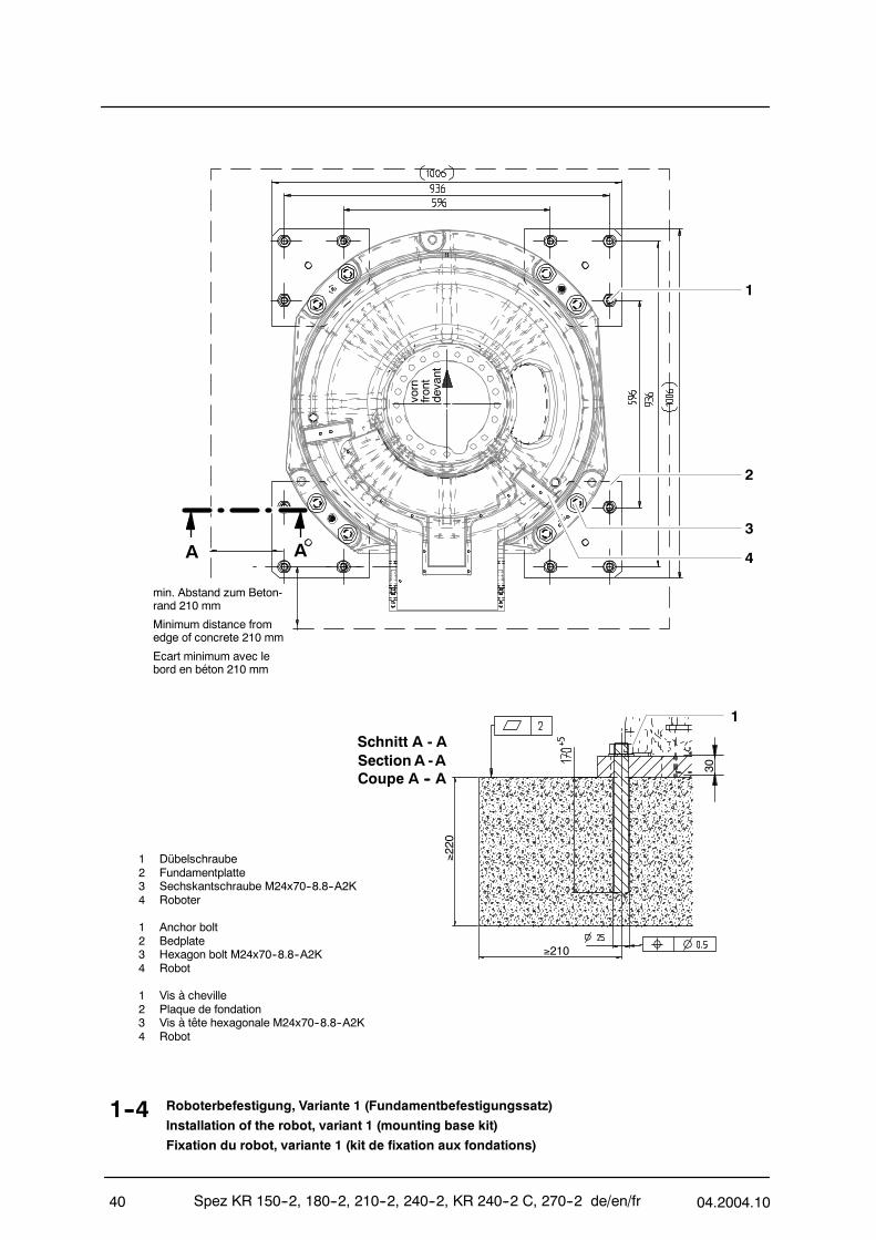
Spez KR 150--2, 180--2, 210--2, 240--2, KR 240--2 C, 270--2 de/en/fr 04.2004.1040
1--4 Roboterbefestigung, Variante 1 (Fundamentbefestigungssatz)
Installation of the robot, variant 1 (mounting base kit)
Fixation du robot, variante 1 (kit de fixation aux fondations)
1 Dübelschraube2 Fundamentplatte3 Sechskantschraube M24x70--8.8--A2K4 Roboter
1 Anchor bolt2 Bedplate3 Hexagon bolt M24x70--8.8--A2K4 Robot
1 Vis à cheville2 Plaque de fondation3 Vis à tête hexagonale M24x70--8.8--A2K4 Robot
vorn
front
devant
1
2
3
4AA
Schnitt A - A
Coupe A -- ASection A -A
min. Abstand zum Beton-rand 210 mm
Minimum distance fromedge of concrete 210 mm
Ecart minimum avec lebord en béton 210 mm
130
≥210
≥220
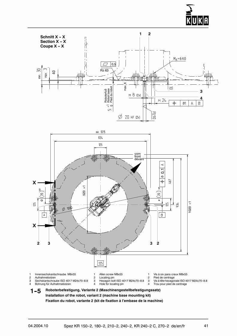
04.2004.10 Spez KR 150--2, 180--2, 210--2, 240--2, KR 240--2 C, 270--2 de/en/fr 41
232 3
X
X
0,1
1020
+1
520+1
1--5 Roboterbefestigung, Variante 2 (Maschinengestellbefestigungssatz)
Installation of the robot, variant 2 (machine base mounting kit)
Fixation du robot, variante 2 (kit de fixation à l’embase de la machine)
vornfrontdevant
21
3max.6
4
40
Rz 63
0,5
Schnitt X -- XSection X -- XCoupe X -- X
Roboterfuß
Robotbase
Pieddu
robot
1 Innensechskantschraube M8x55 1 Allen screw M8x55 1 Vis à six pans creux M8x552 Aufnahmebolzen 2 Locating pin 2 Pied de centrage3 Sechskantschraube ISO 4017 M24x70--8.8 3 Hexagon bolt ISO 4017 M24x70--8.8 3 Vis à tête hexagonale ISO 4017M24x70--8.84 Bohrung für Aufnahmebolzen 4 Hole for locating pin 4 Trou pour pied de centrage
MA=640
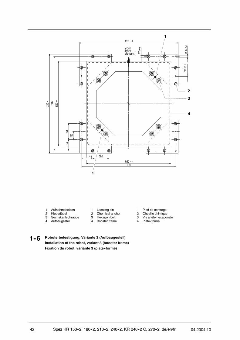
Spez KR 150--2, 180--2, 210--2, 240--2, KR 240--2 C, 270--2 de/en/fr 04.2004.1042
1--6 Roboterbefestigung, Variante 3 (Aufbaugestell)
Installation of the robot, variant 3 (booster frame)
Fixation du robot, variante 3 (plate--forme)
1 Aufnahmebolzen 1 Locating pin 1 Pied de centrage2 Klebedübel 2 Chemical anchor 2 Cheville chimique3 Sechskantschraube 3 Hexagon bolt 3 Vis à tête hexagonale4 Aufbaugestell 4 Booster frame 4 Plate--forme
1
1
2
3
4
vornfrontdevant
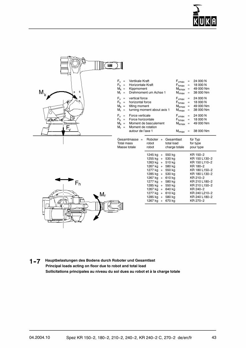
04.2004.10 Spez KR 150--2, 180--2, 210--2, 240--2, KR 240--2 C, 270--2 de/en/fr 43
1--7
Fv = Vertikale Kraft Fvmax = 24 000 NFh = Horizontale Kraft Fhmax = 18 000 NMk = Kippmoment Mkmax = 49 000 NmMr = Drehmoment um Achse 1 Mrmax = 38 000 Nm
Fv = vertical force Fvmax = 24 000 NFh = horizontal force Fhmax = 18 000 NMk = tilting moment Mkmax = 49 000 NmMr = turning moment about axis 1 Mrmax = 38 000 Nm
Fv = Force verticale Fvmax = 24 000 NFh = Force horizontale Fhmax = 18 000 NMk = Moment de basculement Mkmax = 49 000 NmMr = Moment de rotation
autour de l’axe 1 Mrmax = 38 000 Nm
Gesamtmasse = Roboter + Gesamtlast für TypTotal mass robot total load for typeMasse totale robot charge totale pour type
1245 kg + 550 kg KR 150--21255 kg + 530 kg KR 150 L130--21263 kg + 510 kg KR 150 L110--21267 kg + 580 kg KR 180--21277 kg + 550 kg KR 180 L150--21285 kg + 530 kg KR 180 L130--21267 kg + 610 kg KR 210--21277 kg + 580 kg KR 210 L180--21285 kg + 550 kg KR 210 L150--21267 kg + 640 kg KR 240--21277 kg + 610 kg KR 240 L210--21285 kg + 580 kg KR 240 L180--21267 kg + 670 kg KR 270--2
Hauptbelastungen des Bodens durch Roboter und Gesamtlast
Principal loads acting on floor due to robot and total load
Sollicitations principales au niveau du sol dues au robot et à la charge totale
Fv
Mk
Fh
Mr
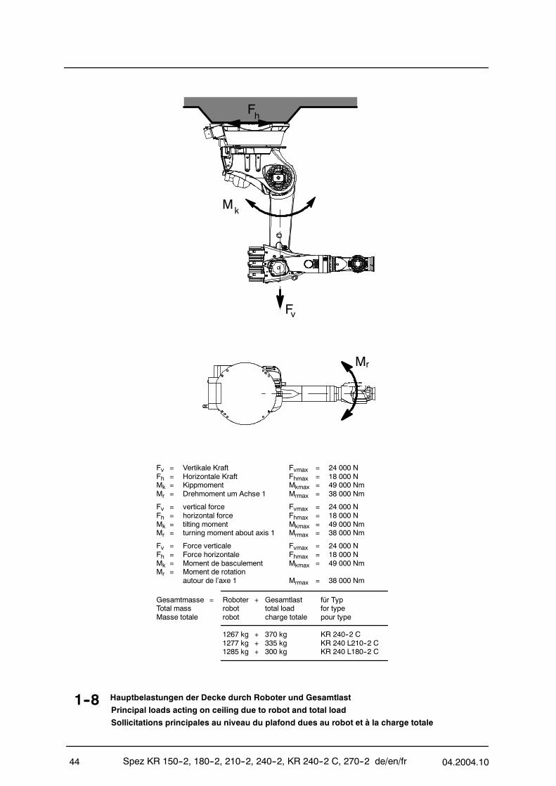
Spez KR 150--2, 180--2, 210--2, 240--2, KR 240--2 C, 270--2 de/en/fr 04.2004.1044
1--8 Hauptbelastungen der Decke durch Roboter und Gesamtlast
Principal loads acting on ceiling due to robot and total load
Sollicitations principales au niveau du plafond dues au robot et à la charge totale
Fh
Fv
Mk
Mr
Fv = Vertikale Kraft Fvmax = 24 000 NFh = Horizontale Kraft Fhmax = 18 000 NMk = Kippmoment Mkmax = 49 000 NmMr = Drehmoment um Achse 1 Mrmax = 38 000 Nm
Fv = vertical force Fvmax = 24 000 NFh = horizontal force Fhmax = 18 000 NMk = tilting moment Mkmax = 49 000 NmMr = turning moment about axis 1 Mrmax = 38 000 Nm
Fv = Force verticale Fvmax = 24 000 NFh = Force horizontale Fhmax = 18 000 NMk = Moment de basculement Mkmax = 49 000 NmMr = Moment de rotation
autour de l’axe 1 Mrmax = 38 000 Nm
Gesamtmasse = Roboter + Gesamtlast für TypTotal mass robot total load for typeMasse totale robot charge totale pour type
1267 kg + 370 kg KR 240--2 C1277 kg + 335 kg KR 240 L210--2 C1285 kg + 300 kg KR 240 L180--2 C
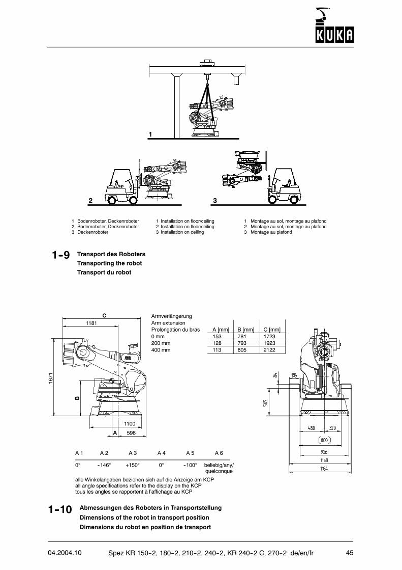
04.2004.10 Spez KR 150--2, 180--2, 210--2, 240--2, KR 240--2 C, 270--2 de/en/fr 45
1--10 Abmessungen des Roboters in Transportstellung
Dimensions of the robot in transport position
Dimensions du robot en position de transport
1
1 Bodenroboter, Deckenroboter 1 Installation on floor/ceiling 1 Montage au sol, montage au plafond2 Bodenroboter, Deckenroboter 2 Installation on floor/ceiling 2 Montage au sol, montage au plafond3 Deckenroboter 3 Installation on ceiling 3 Montage au plafond
ArmverlängerungArm extensionProlongation du bras A [mm] B [mm] C [mm]0 mm 153 781 1723200 mm 128 793 1923400 mm 113 805 2122
C
B
A
1181
598
1100
1671
2 3
A 1 A 2 A 3 A 4 A 5 A 6
0° --146° +150° 0° --100° beliebig/any/quelconque
alle Winkelangaben beziehen sich auf die Anzeige am KCPall angle specifications refer to the display on the KCPtous les angles se rapportent à l’affichage au KCP
1--9 Transport des Roboters
Transporting the robot
Transport du robot
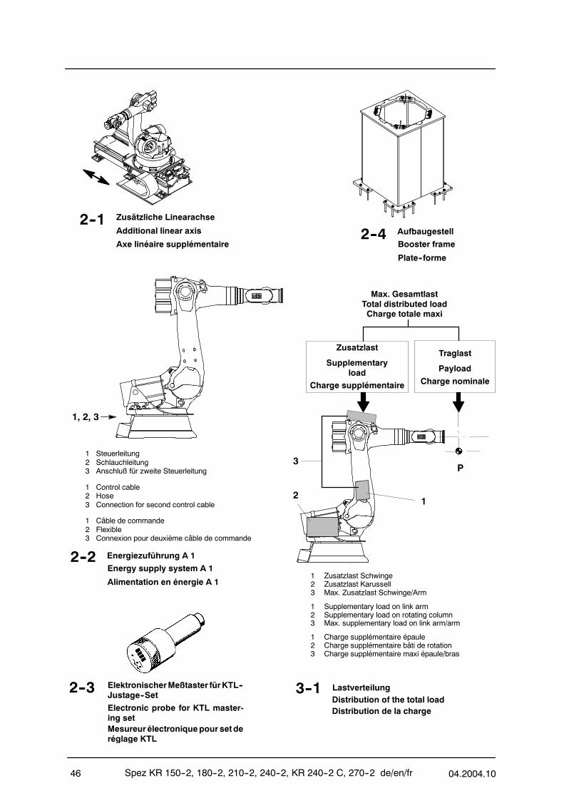
Spez KR 150--2, 180--2, 210--2, 240--2, KR 240--2 C, 270--2 de/en/fr 04.2004.1046
3--1 LastverteilungDistribution of the total loadDistribution de la charge
2--2 Energiezuführung A 1
Energy supply system A 1
Alimentation en énergie A 1
Traglast
Payload
Charge nominale
Max. GesamtlastTotal distributed loadCharge totale maxi
2--3 ElektronischerMeßtaster fürKTL--Justage--Set
Electronic probe for KTL master-ing setMesureurélectroniquepour setderéglage KTL
P
2--1 Zusätzliche Linearachse
Additional linear axis
Axe linéaire supplémentaire
1 Steuerleitung2 Schlauchleitung3 Anschluß für zweite Steuerleitung
1 Control cable2 Hose3 Connection for second control cable
1 Câble de commande2 Flexible3 Connexion pour deuxième câble de commande
Zusatzlast
Supplementaryload
Charge supplémentaire
1, 2, 3
1 Zusatzlast Schwinge2 Zusatzlast Karussell3 Max. Zusatzlast Schwinge/Arm
1 Supplementary load on link arm2 Supplementary load on rotating column3 Max. supplementary load on link arm/arm
1 Charge supplémentaire épaule2 Charge supplémentaire bâti de rotation3 Charge supplémentaire maxi épaule/bras
3
21
2--4 Aufbaugestell
Booster frame
Plate--forme

04.2004.10 Spez KR 150--2, 180--2, 210--2, 240--2, KR 240--2 C, 270--2 de/en/fr 47
HINWEIS: Die hier ermittelten Werte sind für die Robotereinsatzplanung notwendig. Für die Inbetriebnahme des Roboterssind gemäß KUKA--Softwaredokumentation zusätzliche Eingabedaten erforderlich.
NOTE: The values determined here are necessary for planning the robot application. For commissioning the robot, addi-tional input data are required in accordance with the KUKA software documentation.
REMARQUE: Les valeurs ainsi déterminées sont indispensables pour définir le champ d’application du robot. Des donnéessupplémentaires sont nécessaires pour la mise en service du robot conformément à la documentation du logicielKUKA.
3--2 Traglastschwerpunkt P und Belastungskurven für KR 150--2Load center of gravity P and loading curves for KR 150--2Centre de gravité de la charge P et courbes de charge pour KR 150--2
ACHTUNG: DieseBelastungskurvenentsprechender äußerstenBelastbarkeit! Esmüssen immerbeideWerte (Traglastund Eigenträgheitsmoment) geprüft werden. Ein Überschreiten geht in die Lebensdauer des Geräts ein,überlastet im allgemeinen Motoren und Getriebe und bedarf auf alle Fälle der Rücksprache mit KUKA.
IMPORTANT: These loading curves correspond to the maximum load capacity. Both values (payload and principal mo-ment of inertia)must be checked inall cases.Exceeding thiscapacitywill reduce theservice lifeof the robotand generally overload the motors and gears, in any such case KUKA must be consulted.
ATTENTION: Lescourbesdechargereprésentent lacapacitédechargemaximum!Il faut toujoursvérifier lesdeuxvaleurs(charge et moment d’inertie propre). Un dépassement de cette capacité réduit la durée de vie du robot et,en règle générale, surcharge les moteurs ainsi que les engrenages et transmissions. Il faudra en tous casconsulter KUKA auparavant.
Roboterflansch--KoordinatensystemRobot flange coordinate systemSystème de coordonnées bride du robot
--X
Lz
Lx
Ly
+X--Y
+Y
+Z
--Z
Traglastschwerpunkt PLoad center of gravity PCentre de gravité charge P
Lxy= L x2+ Ly2
Lxy
Lxy (mm)
100 200 300 400 500 700600
100
200
300
400
Lz (mm)
500
A 4
A 5
A 6
Zulässige Massenträgheit imAuslegungspunkt (Lxy = 270 mm,Lz = 240 mm) 75 kgm2.
ACHTUNG: Die Massenträgheitenmüssen mit dem Berechnungspro-gramm KUKA Load überprüftwerden. Die Eingabe der Lastdatenin die Steuerung ist unbedingterforderlich!
KR 150--2
Permissible mass inertia at the designpoint (Lxy = 270 mm, Lz = 240 mm)75 kgm2.
IMPORTANT: The mass inertiamust be checked using thecalculation program KUKA Load. Itis imperative for the load data to beentered in the controller!
Inertie de masse autorisée au pointde conception (Lxy = 270 mm,Lz = 240 mm) 75 kgm2.
ATTENTION: Les inerties de massesont à vérifier avec le programmede calculation KUKA Load. L’en-trée des données de charge dansla commande est impérative!
150 kg
100 kg
110 kg
120 kg130 kg
140 kg
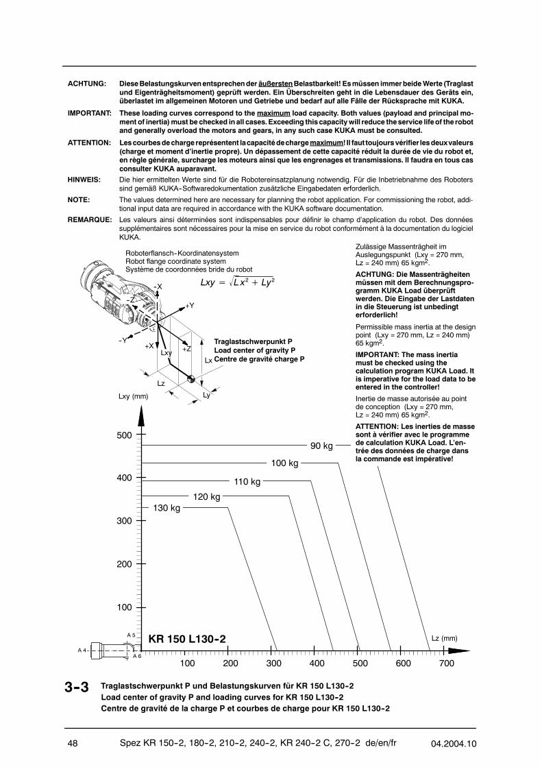
Spez KR 150--2, 180--2, 210--2, 240--2, KR 240--2 C, 270--2 de/en/fr 04.2004.1048
HINWEIS: Die hier ermittelten Werte sind für die Robotereinsatzplanung notwendig. Für die Inbetriebnahme des Roboterssind gemäß KUKA--Softwaredokumentation zusätzliche Eingabedaten erforderlich.
NOTE: The values determined here are necessary for planning the robot application. For commissioning the robot, addi-tional input data are required in accordance with the KUKA software documentation.
REMARQUE: Les valeurs ainsi déterminées sont indispensables pour définir le champ d’application du robot. Des donnéessupplémentaires sont nécessaires pour la mise en service du robot conformément à la documentation du logicielKUKA.
3--3 Traglastschwerpunkt P und Belastungskurven für KR 150 L130--2Load center of gravity P and loading curves for KR 150 L130--2Centre de gravité de la charge P et courbes de charge pour KR 150 L130--2
ACHTUNG: DieseBelastungskurvenentsprechender äußerstenBelastbarkeit! Esmüssen immerbeideWerte (Traglastund Eigenträgheitsmoment) geprüft werden. Ein Überschreiten geht in die Lebensdauer des Geräts ein,überlastet im allgemeinen Motoren und Getriebe und bedarf auf alle Fälle der Rücksprache mit KUKA.
IMPORTANT: These loading curves correspond to the maximum load capacity. Both values (payload and principal mo-ment of inertia)must be checked inall cases.Exceeding thiscapacitywill reduce theservice lifeof the robotand generally overload the motors and gears, in any such case KUKA must be consulted.
ATTENTION: Lescourbesdechargereprésentent lacapacitédechargemaximum!Il faut toujoursvérifier lesdeuxvaleurs(charge et moment d’inertie propre). Un dépassement de cette capacité réduit la durée de vie du robot et,en règle générale, surcharge les moteurs ainsi que les engrenages et transmissions. Il faudra en tous casconsulter KUKA auparavant.
Roboterflansch--KoordinatensystemRobot flange coordinate systemSystème de coordonnées bride du robot
--X
Lz
Lx
Ly
+X--Y
+Y
+Z
--Z
Traglastschwerpunkt PLoad center of gravity PCentre de gravité charge P
Lxy= L x2+ Ly2
Lxy
Zulässige Massenträgheit imAuslegungspunkt (Lxy = 270 mm,Lz = 240 mm) 65 kgm2.
ACHTUNG: Die Massenträgheitenmüssen mit dem Berechnungspro-gramm KUKA Load überprüftwerden. Die Eingabe der Lastdatenin die Steuerung ist unbedingterforderlich!
Permissible mass inertia at the designpoint (Lxy = 270 mm, Lz = 240 mm)65 kgm2.
IMPORTANT: The mass inertiamust be checked using thecalculation program KUKA Load. Itis imperative for the load data to beentered in the controller!
Lxy (mm)
100 200 300 400 500 700600
100
200
300
400
Lz (mm)
500
A 4
A 5
A 6
KR 150 L130--2
Inertie de masse autorisée au pointde conception (Lxy = 270 mm,Lz = 240 mm) 65 kgm2.
ATTENTION: Les inerties de massesont à vérifier avec le programmede calculation KUKA Load. L’en-trée des données de charge dansla commande est impérative!
110 kg
120 kg130 kg
90 kg
100 kg

04.2004.10 Spez KR 150--2, 180--2, 210--2, 240--2, KR 240--2 C, 270--2 de/en/fr 49
HINWEIS: Die hier ermittelten Werte sind für die Robotereinsatzplanung notwendig. Für die Inbetriebnahme des Roboterssind gemäß KUKA--Softwaredokumentation zusätzliche Eingabedaten erforderlich.
NOTE: The values determined here are necessary for planning the robot application. For commissioning the robot, addi-tional input data are required in accordance with the KUKA software documentation.
REMARQUE: Les valeurs ainsi déterminées sont indispensables pour définir le champ d’application du robot. Des donnéessupplémentaires sont nécessaires pour la mise en service du robot conformément à la documentation du logicielKUKA.
3--4 Traglastschwerpunkt P und Belastungskurven für KR 150 L110--2Load center of gravity P and loading curves for KR 150 L110--2Centre de gravité de la charge P et courbes de charge pour KR 150 L110--2
ACHTUNG: DieseBelastungskurvenentsprechender äußerstenBelastbarkeit! Esmüssen immerbeideWerte (Traglastund Eigenträgheitsmoment) geprüft werden. Ein Überschreiten geht in die Lebensdauer des Geräts ein,überlastet im allgemeinen Motoren und Getriebe und bedarf auf alle Fälle der Rücksprache mit KUKA.
IMPORTANT: These loading curves correspond to the maximum load capacity. Both values (payload and principal mo-ment of inertia)must be checked inall cases.Exceeding thiscapacitywill reduce theservice lifeof the robotand generally overload the motors and gears, in any such case KUKA must be consulted.
ATTENTION: Lescourbesdechargereprésentent lacapacitédechargemaximum!Il faut toujoursvérifier lesdeuxvaleurs(charge et moment d’inertie propre). Un dépassement de cette capacité réduit la durée de vie du robot et,en règle générale, surcharge les moteurs ainsi que les engrenages et transmissions. Il faudra en tous casconsulter KUKA auparavant.
Roboterflansch--KoordinatensystemRobot flange coordinate systemSystème de coordonnées bride du robot
--X
Lz
Lx
Ly
+X--Y
+Y
+Z
--Z
Traglastschwerpunkt PLoad center of gravity PCentre de gravité charge P
Lxy= L x2+ Ly2
Lxy
Zulässige Massenträgheit imAuslegungspunkt (Lxy = 270 mm,Lz = 240 mm) 55 kgm2.
ACHTUNG: Die Massenträgheitenmüssen mit dem Berechnungspro-gramm KUKA Load überprüftwerden. Die Eingabe der Lastdatenin die Steuerung ist unbedingterforderlich!
Permissible mass inertia at the designpoint (Lxy = 270 mm, Lz = 240 mm)55 kgm2.
IMPORTANT: The mass inertiamust be checked using thecalculation program KUKA Load. Itis imperative for the load data to beentered in the controller!
Lxy (mm)
100 200 300 400 500 700600
100
200
300
400
Lz (mm)
500
A 4
A 5
A 6
KR 150 L110--2
Inertie de masse autorisée au pointde conception (Lxy = 270 mm,Lz = 240 mm) 55 kgm2.
ATTENTION: Les inerties de massesont à vérifier avec le programmede calculation KUKA Load. L’en-trée des données de charge dansla commande est impérative!
90 kg
110 kg
100 kg
80 kg
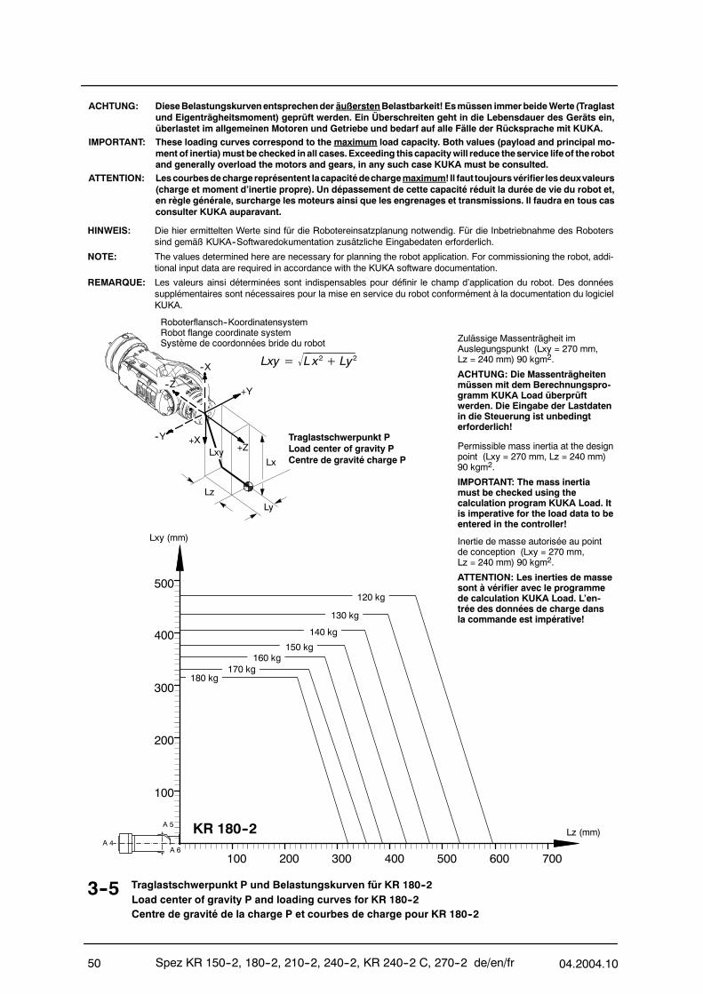
Spez KR 150--2, 180--2, 210--2, 240--2, KR 240--2 C, 270--2 de/en/fr 04.2004.1050
3--5 Traglastschwerpunkt P und Belastungskurven für KR 180--2Load center of gravity P and loading curves for KR 180--2Centre de gravité de la charge P et courbes de charge pour KR 180--2
ACHTUNG: DieseBelastungskurvenentsprechender äußerstenBelastbarkeit! Esmüssen immerbeideWerte (Traglastund Eigenträgheitsmoment) geprüft werden. Ein Überschreiten geht in die Lebensdauer des Geräts ein,überlastet im allgemeinen Motoren und Getriebe und bedarf auf alle Fälle der Rücksprache mit KUKA.
IMPORTANT: These loading curves correspond to the maximum load capacity. Both values (payload and principal mo-ment of inertia)must be checked inall cases.Exceeding thiscapacitywill reduce theservice lifeof the robotand generally overload the motors and gears, in any such case KUKA must be consulted.
ATTENTION: Lescourbesdechargereprésentent lacapacitédechargemaximum!Il faut toujoursvérifier lesdeuxvaleurs(charge et moment d’inertie propre). Un dépassement de cette capacité réduit la durée de vie du robot et,en règle générale, surcharge les moteurs ainsi que les engrenages et transmissions. Il faudra en tous casconsulter KUKA auparavant.
HINWEIS: Die hier ermittelten Werte sind für die Robotereinsatzplanung notwendig. Für die Inbetriebnahme des Roboterssind gemäß KUKA--Softwaredokumentation zusätzliche Eingabedaten erforderlich.
NOTE: The values determined here are necessary for planning the robot application. For commissioning the robot, addi-tional input data are required in accordance with the KUKA software documentation.
REMARQUE: Les valeurs ainsi déterminées sont indispensables pour définir le champ d’application du robot. Des donnéessupplémentaires sont nécessaires pour la mise en service du robot conformément à la documentation du logicielKUKA.
Roboterflansch--KoordinatensystemRobot flange coordinate systemSystème de coordonnées bride du robot
--X
Lz
Lx
Ly
+X--Y
+Y
+Z
--Z
Traglastschwerpunkt PLoad center of gravity PCentre de gravité charge P
Lxy= L x2+ Ly2
Lxy
Lxy (mm)
100 200 300 400 500 700600
100
200
300
400
Lz (mm)
500
A 4
A 5
A 6
KR 180--2
Zulässige Massenträgheit imAuslegungspunkt (Lxy = 270 mm,Lz = 240 mm) 90 kgm2.
ACHTUNG: Die Massenträgheitenmüssen mit dem Berechnungspro-gramm KUKA Load überprüftwerden. Die Eingabe der Lastdatenin die Steuerung ist unbedingterforderlich!
Permissible mass inertia at the designpoint (Lxy = 270 mm, Lz = 240 mm)90 kgm2.
IMPORTANT: The mass inertiamust be checked using thecalculation program KUKA Load. Itis imperative for the load data to beentered in the controller!
140 kg
150 kg160 kg
130 kg
170 kg
120 kg
180 kg
Inertie de masse autorisée au pointde conception (Lxy = 270 mm,Lz = 240 mm) 90 kgm2.
ATTENTION: Les inerties de massesont à vérifier avec le programmede calculation KUKA Load. L’en-trée des données de charge dansla commande est impérative!
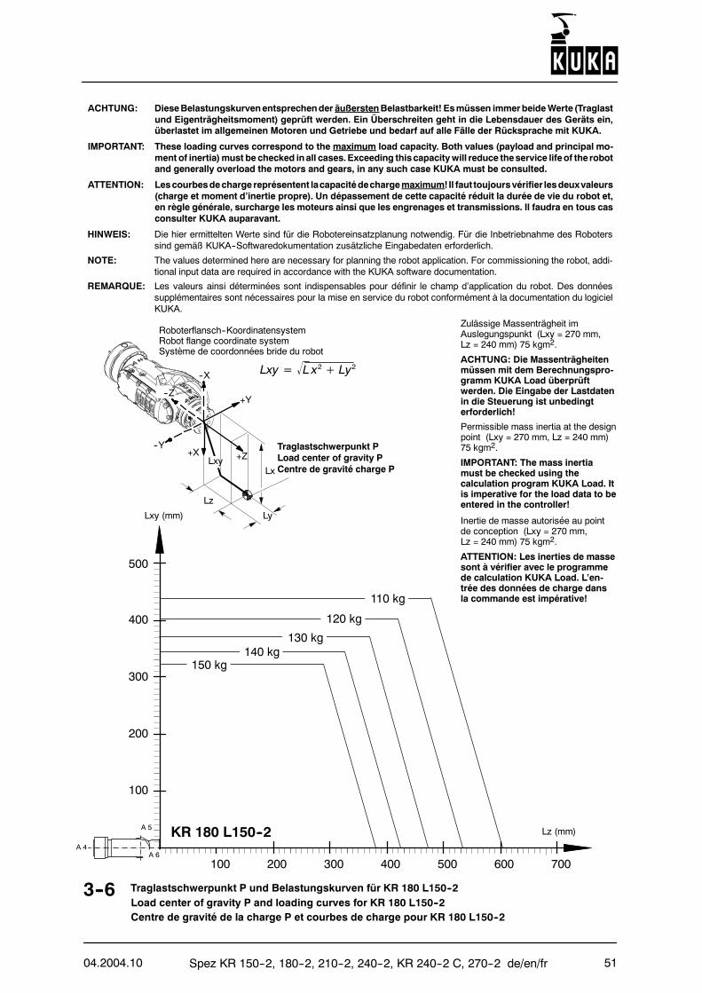
04.2004.10 Spez KR 150--2, 180--2, 210--2, 240--2, KR 240--2 C, 270--2 de/en/fr 51
HINWEIS: Die hier ermittelten Werte sind für die Robotereinsatzplanung notwendig. Für die Inbetriebnahme des Roboterssind gemäß KUKA--Softwaredokumentation zusätzliche Eingabedaten erforderlich.
NOTE: The values determined here are necessary for planning the robot application. For commissioning the robot, addi-tional input data are required in accordance with the KUKA software documentation.
REMARQUE: Les valeurs ainsi déterminées sont indispensables pour définir le champ d’application du robot. Des donnéessupplémentaires sont nécessaires pour la mise en service du robot conformément à la documentation du logicielKUKA.
3--6 Traglastschwerpunkt P und Belastungskurven für KR 180 L150--2Load center of gravity P and loading curves for KR 180 L150--2Centre de gravité de la charge P et courbes de charge pour KR 180 L150--2
ACHTUNG: DieseBelastungskurvenentsprechender äußerstenBelastbarkeit! Esmüssen immerbeideWerte (Traglastund Eigenträgheitsmoment) geprüft werden. Ein Überschreiten geht in die Lebensdauer des Geräts ein,überlastet im allgemeinen Motoren und Getriebe und bedarf auf alle Fälle der Rücksprache mit KUKA.
IMPORTANT: These loading curves correspond to the maximum load capacity. Both values (payload and principal mo-ment of inertia)must be checked inall cases.Exceeding thiscapacitywill reduce theservice lifeof the robotand generally overload the motors and gears, in any such case KUKA must be consulted.
ATTENTION: Lescourbesdechargereprésentent lacapacitédechargemaximum!Il faut toujoursvérifier lesdeuxvaleurs(charge et moment d’inertie propre). Un dépassement de cette capacité réduit la durée de vie du robot et,en règle générale, surcharge les moteurs ainsi que les engrenages et transmissions. Il faudra en tous casconsulter KUKA auparavant.
Roboterflansch--KoordinatensystemRobot flange coordinate systemSystème de coordonnées bride du robot
--X
Lz
Lx
Ly
+X--Y
+Y
+Z
--Z
Traglastschwerpunkt PLoad center of gravity PCentre de gravité charge P
Lxy= L x2+ Ly2
Lxy
Zulässige Massenträgheit imAuslegungspunkt (Lxy = 270 mm,Lz = 240 mm) 75 kgm2.
ACHTUNG: Die Massenträgheitenmüssen mit dem Berechnungspro-gramm KUKA Load überprüftwerden. Die Eingabe der Lastdatenin die Steuerung ist unbedingterforderlich!
Permissible mass inertia at the designpoint (Lxy = 270 mm, Lz = 240 mm)75 kgm2.
IMPORTANT: The mass inertiamust be checked using thecalculation program KUKA Load. Itis imperative for the load data to beentered in the controller!
Inertie de masse autorisée au pointde conception (Lxy = 270 mm,Lz = 240 mm) 75 kgm2.
ATTENTION: Les inerties de massesont à vérifier avec le programmede calculation KUKA Load. L’en-trée des données de charge dansla commande est impérative!
Lxy (mm)
100 200 300 400 500 700600
100
200
300
400
Lz (mm)
500
A 4
A 5
A 6
KR 180 L150--2
110 kg
120 kg
130 kg
150 kg140 kg
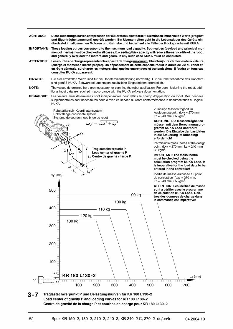
Spez KR 150--2, 180--2, 210--2, 240--2, KR 240--2 C, 270--2 de/en/fr 04.2004.1052
HINWEIS: Die hier ermittelten Werte sind für die Robotereinsatzplanung notwendig. Für die Inbetriebnahme des Roboterssind gemäß KUKA--Softwaredokumentation zusätzliche Eingabedaten erforderlich.
NOTE: The values determined here are necessary for planning the robot application. For commissioning the robot, addi-tional input data are required in accordance with the KUKA software documentation.
REMARQUE: Les valeurs ainsi déterminées sont indispensables pour définir le champ d’application du robot. Des donnéessupplémentaires sont nécessaires pour la mise en service du robot conformément à la documentation du logicielKUKA.
3--7 Traglastschwerpunkt P und Belastungskurven für KR 180 L130--2Load center of gravity P and loading curves for KR 180 L130--2Centre de gravité de la charge P et courbes de charge pour KR 180 L130--2
ACHTUNG: DieseBelastungskurvenentsprechender äußerstenBelastbarkeit! Esmüssen immerbeideWerte (Traglastund Eigenträgheitsmoment) geprüft werden. Ein Überschreiten geht in die Lebensdauer des Geräts ein,überlastet im allgemeinen Motoren und Getriebe und bedarf auf alle Fälle der Rücksprache mit KUKA.
IMPORTANT: These loading curves correspond to the maximum load capacity. Both values (payload and principal mo-ment of inertia)must be checked inall cases.Exceeding thiscapacitywill reduce theservice lifeof the robotand generally overload the motors and gears, in any such case KUKA must be consulted.
ATTENTION: Lescourbesdechargereprésentent lacapacitédechargemaximum!Il faut toujoursvérifier lesdeuxvaleurs(charge et moment d’inertie propre). Un dépassement de cette capacité réduit la durée de vie du robot et,en règle générale, surcharge les moteurs ainsi que les engrenages et transmissions. Il faudra en tous casconsulter KUKA auparavant.
Roboterflansch--KoordinatensystemRobot flange coordinate systemSystème de coordonnées bride du robot
--X
Lz
Lx
Ly
+X--Y
+Y
+Z
--Z
Traglastschwerpunkt PLoad center of gravity PCentre de gravité charge P
Lxy= L x2+ Ly2
Lxy
Zulässige Massenträgheit imAuslegungspunkt (Lxy = 270 mm,Lz = 240 mm) 65 kgm2.
ACHTUNG: Die Massenträgheitenmüssen mit dem Berechnungspro-gramm KUKA Load überprüftwerden. Die Eingabe der Lastdatenin die Steuerung ist unbedingterforderlich!
Permissible mass inertia at the designpoint (Lxy = 270 mm, Lz = 240 mm)65 kgm2.
IMPORTANT: The mass inertiamust be checked using thecalculation program KUKA Load. Itis imperative for the load data to beentered in the controller!
Lxy (mm)
100 200 300 400 500 700600
100
200
300
400
Lz (mm)
500
A 4
A 5
A 6
KR 180 L130--2
Inertie de masse autorisée au pointde conception (Lxy = 270 mm,Lz = 240 mm) 65 kgm2.
ATTENTION: Les inerties de massesont à vérifier avec le programmede calculation KUKA Load. L’en-trée des données de charge dansla commande est impérative!
110 kg
120 kg130 kg
90 kg
100 kg
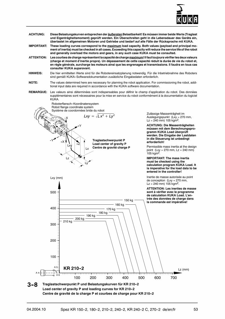
04.2004.10 Spez KR 150--2, 180--2, 210--2, 240--2, KR 240--2 C, 270--2 de/en/fr 53
3--8 Traglastschwerpunkt P und Belastungskurven für KR 210--2Load center of gravity P and loading curves for KR 210--2Centre de gravité de la charge P et courbes de charge pour KR 210--2
ACHTUNG: DieseBelastungskurvenentsprechender äußerstenBelastbarkeit! Esmüssen immerbeideWerte (Traglastund Eigenträgheitsmoment) geprüft werden. Ein Überschreiten geht in die Lebensdauer des Geräts ein,überlastet im allgemeinen Motoren und Getriebe und bedarf auf alle Fälle der Rücksprache mit KUKA.
IMPORTANT: These loading curves correspond to the maximum load capacity. Both values (payload and principal mo-ment of inertia)must be checked inall cases.Exceeding thiscapacitywill reduce theservice lifeof the robotand generally overload the motors and gears, in any such case KUKA must be consulted.
ATTENTION: Lescourbesdechargereprésentent lacapacitédechargemaximum!Il faut toujoursvérifier lesdeuxvaleurs(charge et moment d’inertie propre). Un dépassement de cette capacité réduit la durée de vie du robot et,en règle générale, surcharge les moteurs ainsi que les engrenages et transmissions. Il faudra en tous casconsulter KUKA auparavant.
HINWEIS: Die hier ermittelten Werte sind für die Robotereinsatzplanung notwendig. Für die Inbetriebnahme des Roboterssind gemäß KUKA--Softwaredokumentation zusätzliche Eingabedaten erforderlich.
NOTE: The values determined here are necessary for planning the robot application. For commissioning the robot, addi-tional input data are required in accordance with the KUKA software documentation.
REMARQUE: Les valeurs ainsi déterminées sont indispensables pour définir le champ d’application du robot. Des donnéessupplémentaires sont nécessaires pour la mise en service du robot conformément à la documentation du logicielKUKA.
Roboterflansch--KoordinatensystemRobot flange coordinate systemSystème de coordonnées bride du robot
--X
Lz
Lx
Ly
+X--Y
+Y
+Z
--Z
Traglastschwerpunkt PLoad center of gravity PCentre de gravité charge P
Lxy= L x2+ Ly2
Lxy
Lxy (mm)
100 200 300 400 500 700600
100
200
300
400
Lz (mm)
500
A 4
A 5
A 6
KR 210--2
Zulässige Massenträgheit imAuslegungspunkt (Lxy = 270 mm,Lz = 240 mm) 105 kgm2.
ACHTUNG: Die Massenträgheitenmüssen mit dem Berechnungspro-gramm KUKA Load überprüftwerden. Die Eingabe der Lastdatenin die Steuerung ist unbedingterforderlich!
Permissible mass inertia at the designpoint (Lxy = 270 mm, Lz = 240 mm)105 kgm2.
IMPORTANT: The mass inertiamust be checked using thecalculation program KUKA Load. Itis imperative for the load data to beentered in the controller!
Inertie de masse autorisée au pointde conception (Lxy = 270 mm,Lz = 240 mm) 105 kgm2.
ATTENTION: Les inerties de massesont à vérifier avec le programmede calculation KUKA Load. L’en-trée des données de charge dansla commande est impérative!
170 kg180 kg
200 kg
150 kg
160 kg
210 kg
190 kg
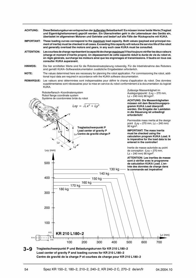
Spez KR 150--2, 180--2, 210--2, 240--2, KR 240--2 C, 270--2 de/en/fr 04.2004.1054
HINWEIS: Die hier ermittelten Werte sind für die Robotereinsatzplanung notwendig. Für die Inbetriebnahme des Roboterssind gemäß KUKA--Softwaredokumentation zusätzliche Eingabedaten erforderlich.
NOTE: The values determined here are necessary for planning the robot application. For commissioning the robot, addi-tional input data are required in accordance with the KUKA software documentation.
REMARQUE: Les valeurs ainsi déterminées sont indispensables pour définir le champ d’application du robot. Des donnéessupplémentaires sont nécessaires pour la mise en service du robot conformément à la documentation du logicielKUKA.
3--9 Traglastschwerpunkt P und Belastungskurven für KR 210 L180--2Load center of gravity P and loading curves for KR 210 L180--2Centre de gravité de la charge P et courbes de charge pour KR 210 L180--2
ACHTUNG: DieseBelastungskurvenentsprechender äußerstenBelastbarkeit! Esmüssen immerbeideWerte (Traglastund Eigenträgheitsmoment) geprüft werden. Ein Überschreiten geht in die Lebensdauer des Geräts ein,überlastet im allgemeinen Motoren und Getriebe und bedarf auf alle Fälle der Rücksprache mit KUKA.
IMPORTANT: These loading curves correspond to the maximum load capacity. Both values (payload and principal mo-ment of inertia)must be checked inall cases.Exceeding thiscapacitywill reduce theservice lifeof the robotand generally overload the motors and gears, in any such case KUKA must be consulted.
ATTENTION: Lescourbesdechargereprésentent lacapacitédechargemaximum!Il faut toujoursvérifier lesdeuxvaleurs(charge et moment d’inertie propre). Un dépassement de cette capacité réduit la durée de vie du robot et,en règle générale, surcharge les moteurs ainsi que les engrenages et transmissions. Il faudra en tous casconsulter KUKA auparavant.
Roboterflansch--KoordinatensystemRobot flange coordinate systemSystème de coordonnées bride du robot
--X
Lz
Lx
Ly
+X--Y
+Y
+Z
--Z
Traglastschwerpunkt PLoad center of gravity PCentre de gravité charge P
Lxy= L x2+ Ly2
Lxy
Lxy (mm)
100 200 300 400 500 700600
100
200
300
400
Lz (mm)
500
A 4
A 5
A 6
KR 210 L180--2
Zulässige Massenträgheit imAuslegungspunkt (Lxy = 270 mm,Lz = 240 mm) 90 kgm2.
ACHTUNG: Die Massenträgheitenmüssen mit dem Berechnungspro-gramm KUKA Load überprüftwerden. Die Eingabe der Lastdatenin die Steuerung ist unbedingterforderlich!
Permissible mass inertia at the designpoint (Lxy = 270 mm, Lz = 240 mm)90 kgm2.
IMPORTANT: The mass inertiamust be checked using thecalculation program KUKA Load. Itis imperative for the load data to beentered in the controller!
Inertie de masse autorisée au pointde conception (Lxy = 270 mm,Lz = 240 mm) 90 kgm2.
ATTENTION: Les inerties de massesont à vérifier avec le programmede calculation KUKA Load. L’en-trée des données de charge dansla commande est impérative!
140 kg
150 kg160 kg
180 kg170 kg
130 kg

04.2004.10 Spez KR 150--2, 180--2, 210--2, 240--2, KR 240--2 C, 270--2 de/en/fr 55
HINWEIS: Die hier ermittelten Werte sind für die Robotereinsatzplanung notwendig. Für die Inbetriebnahme des Roboterssind gemäß KUKA--Softwaredokumentation zusätzliche Eingabedaten erforderlich.
NOTE: The values determined here are necessary for planning the robot application. For commissioning the robot, addi-tional input data are required in accordance with the KUKA software documentation.
REMARQUE: Les valeurs ainsi déterminées sont indispensables pour définir le champ d’application du robot. Des donnéessupplémentaires sont nécessaires pour la mise en service du robot conformément à la documentation du logicielKUKA.
3--10 Traglastschwerpunkt P und Belastungskurven für KR 210 L150--2Load center of gravity P and loading curves for KR 210 L150--2Centre de gravité de la charge P et courbes de charge pour KR 210 L150--2
ACHTUNG: DieseBelastungskurvenentsprechender äußerstenBelastbarkeit! Esmüssen immerbeideWerte (Traglastund Eigenträgheitsmoment) geprüft werden. Ein Überschreiten geht in die Lebensdauer des Geräts ein,überlastet im allgemeinen Motoren und Getriebe und bedarf auf alle Fälle der Rücksprache mit KUKA.
IMPORTANT: These loading curves correspond to the maximum load capacity. Both values (payload and principal mo-ment of inertia)must be checked inall cases.Exceeding thiscapacitywill reduce theservice lifeof the robotand generally overload the motors and gears, in any such case KUKA must be consulted.
ATTENTION: Lescourbesdechargereprésentent lacapacitédechargemaximum!Il faut toujoursvérifier lesdeuxvaleurs(charge et moment d’inertie propre). Un dépassement de cette capacité réduit la durée de vie du robot et,en règle générale, surcharge les moteurs ainsi que les engrenages et transmissions. Il faudra en tous casconsulter KUKA auparavant.
Roboterflansch--KoordinatensystemRobot flange coordinate systemSystème de coordonnées bride du robot
--X
Lz
Lx
Ly
+X--Y
+Y
+Z
--Z
Traglastschwerpunkt PLoad center of gravity PCentre de gravité charge P
Lxy= L x2+ Ly2
Lxy
Zulässige Massenträgheit imAuslegungspunkt (Lxy = 270 mm,Lz = 240 mm) 75 kgm2.
ACHTUNG: Die Massenträgheitenmüssen mit dem Berechnungspro-gramm KUKA Load überprüftwerden. Die Eingabe der Lastdatenin die Steuerung ist unbedingterforderlich!
Permissible mass inertia at the designpoint (Lxy = 270 mm, Lz = 240 mm)75 kgm2.
IMPORTANT: The mass inertiamust be checked using thecalculation program KUKA Load. Itis imperative for the load data to beentered in the controller!
Inertie de masse autorisée au pointde conception (Lxy = 270 mm,Lz = 240 mm) 75 kgm2.
ATTENTION: Les inerties de massesont à vérifier avec le programmede calculation KUKA Load. L’en-trée des données de charge dansla commande est impérative!
Lxy (mm)
100 200 300 400 500 700600
100
200
300
400
Lz (mm)
500
A 4
A 5
A 6
KR 210 L150--2
140 kg
110 kg
120 kg130 kg
150 kg
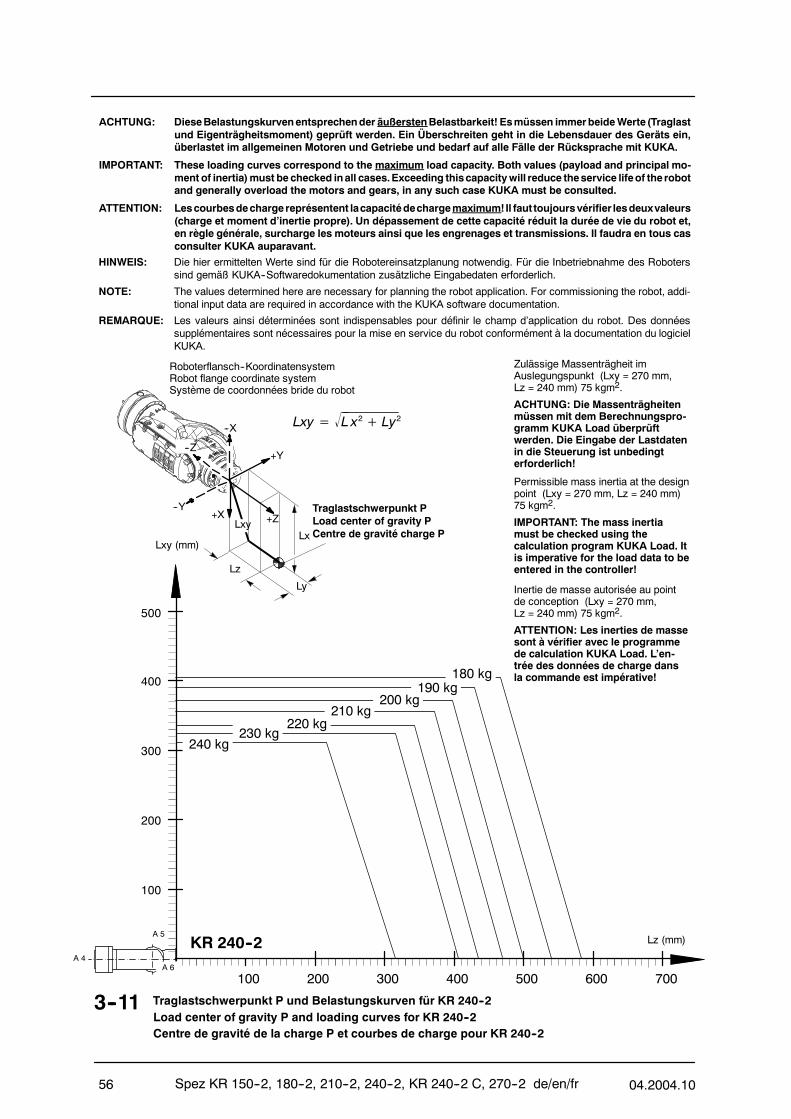
Spez KR 150--2, 180--2, 210--2, 240--2, KR 240--2 C, 270--2 de/en/fr 04.2004.1056
HINWEIS: Die hier ermittelten Werte sind für die Robotereinsatzplanung notwendig. Für die Inbetriebnahme des Roboterssind gemäß KUKA--Softwaredokumentation zusätzliche Eingabedaten erforderlich.
NOTE: The values determined here are necessary for planning the robot application. For commissioning the robot, addi-tional input data are required in accordance with the KUKA software documentation.
REMARQUE: Les valeurs ainsi déterminées sont indispensables pour définir le champ d’application du robot. Des donnéessupplémentaires sont nécessaires pour la mise en service du robot conformément à la documentation du logicielKUKA.
3--11 Traglastschwerpunkt P und Belastungskurven für KR 240--2Load center of gravity P and loading curves for KR 240--2Centre de gravité de la charge P et courbes de charge pour KR 240--2
ACHTUNG: DieseBelastungskurvenentsprechender äußerstenBelastbarkeit! Esmüssen immerbeideWerte (Traglastund Eigenträgheitsmoment) geprüft werden. Ein Überschreiten geht in die Lebensdauer des Geräts ein,überlastet im allgemeinen Motoren und Getriebe und bedarf auf alle Fälle der Rücksprache mit KUKA.
IMPORTANT: These loading curves correspond to the maximum load capacity. Both values (payload and principal mo-ment of inertia)must be checked inall cases.Exceeding thiscapacitywill reduce theservice lifeof the robotand generally overload the motors and gears, in any such case KUKA must be consulted.
ATTENTION: Lescourbesdechargereprésentent lacapacitédechargemaximum!Il faut toujoursvérifier lesdeuxvaleurs(charge et moment d’inertie propre). Un dépassement de cette capacité réduit la durée de vie du robot et,en règle générale, surcharge les moteurs ainsi que les engrenages et transmissions. Il faudra en tous casconsulter KUKA auparavant.
Roboterflansch--KoordinatensystemRobot flange coordinate systemSystème de coordonnées bride du robot
--X
Lz
Lx
Ly
+X--Y
+Y
+Z
--Z
Traglastschwerpunkt PLoad center of gravity PCentre de gravité charge P
Lxy= L x2+ Ly2
Lxy
Zulässige Massenträgheit imAuslegungspunkt (Lxy = 270 mm,Lz = 240 mm) 75 kgm2.
ACHTUNG: Die Massenträgheitenmüssen mit dem Berechnungspro-gramm KUKA Load überprüftwerden. Die Eingabe der Lastdatenin die Steuerung ist unbedingterforderlich!
Permissible mass inertia at the designpoint (Lxy = 270 mm, Lz = 240 mm)75 kgm2.
IMPORTANT: The mass inertiamust be checked using thecalculation program KUKA Load. Itis imperative for the load data to beentered in the controller!
Inertie de masse autorisée au pointde conception (Lxy = 270 mm,Lz = 240 mm) 75 kgm2.
ATTENTION: Les inerties de massesont à vérifier avec le programmede calculation KUKA Load. L’en-trée des données de charge dansla commande est impérative!
Lxy (mm)
100 200 300 400 500 700600
100
200
300
400
Lz (mm)
500
A 4
A 5
A 6
KR 240--2
240 kg
220 kg210 kg
200 kg190 kg
180 kg
230 kg

04.2004.10 Spez KR 150--2, 180--2, 210--2, 240--2, KR 240--2 C, 270--2 de/en/fr 57
HINWEIS: Die hier ermittelten Werte sind für die Robotereinsatzplanung notwendig. Für die Inbetriebnahme des Roboterssind gemäß KUKA--Softwaredokumentation zusätzliche Eingabedaten erforderlich.
NOTE: The values determined here are necessary for planning the robot application. For commissioning the robot, addi-tional input data are required in accordance with the KUKA software documentation.
REMARQUE: Les valeurs ainsi déterminées sont indispensables pour définir le champ d’application du robot. Des donnéessupplémentaires sont nécessaires pour la mise en service du robot conformément à la documentation du logicielKUKA.
3--12 Traglastschwerpunkt P und Belastungskurven für KR 240 L210--2Load center of gravity P and loading curves for KR 240 L210--2Centre de gravité de la charge P et courbes de charge pour KR 240 L210--2
ACHTUNG: DieseBelastungskurvenentsprechender äußerstenBelastbarkeit! Esmüssen immerbeideWerte (Traglastund Eigenträgheitsmoment) geprüft werden. Ein Überschreiten geht in die Lebensdauer des Geräts ein,überlastet im allgemeinen Motoren und Getriebe und bedarf auf alle Fälle der Rücksprache mit KUKA.
IMPORTANT: These loading curves correspond to the maximum load capacity. Both values (payload and principal mo-ment of inertia)must be checked inall cases.Exceeding thiscapacitywill reduce theservice lifeof the robotand generally overload the motors and gears, in any such case KUKA must be consulted.
ATTENTION: Lescourbesdechargereprésentent lacapacitédechargemaximum!Il faut toujoursvérifier lesdeuxvaleurs(charge et moment d’inertie propre). Un dépassement de cette capacité réduit la durée de vie du robot et,en règle générale, surcharge les moteurs ainsi que les engrenages et transmissions. Il faudra en tous casconsulter KUKA auparavant.
Roboterflansch--KoordinatensystemRobot flange coordinate systemSystème de coordonnées bride du robot
--X
Lz
Lx
Ly
+X--Y
+Y
+Z
--Z
Traglastschwerpunkt PLoad center of gravity PCentre de gravité charge P
Lxy= L x2+ Ly2
Lxy
Lxy (mm)
100 200 300 400 500 700600
100
200
300
400
Lz (mm)
500
A 4
A 5
A 6
KR 240 L210--2
210 kg200 kg
190 kg180 kg
170 kg160 kg
150 kg
Zulässige Massenträgheit imAuslegungspunkt (Lxy = 270 mm,Lz = 240 mm) 75 kgm2.
ACHTUNG: Die Massenträgheitenmüssen mit dem Berechnungspro-gramm KUKA Load überprüftwerden. Die Eingabe der Lastdatenin die Steuerung ist unbedingterforderlich!
Permissible mass inertia at the designpoint (Lxy = 270 mm, Lz = 240 mm)75 kgm2.
IMPORTANT: The mass inertiamust be checked using thecalculation program KUKA Load. Itis imperative for the load data to beentered in the controller!
Inertie de masse autorisée au pointde conception (Lxy = 270 mm,Lz = 240 mm) 75 kgm2.
ATTENTION: Les inerties de massesont à vérifier avec le programmede calculation KUKA Load. L’en-trée des données de charge dansla commande est impérative!
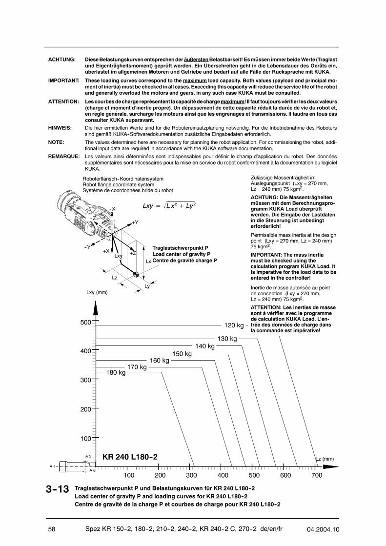
Spez KR 150--2, 180--2, 210--2, 240--2, KR 240--2 C, 270--2 de/en/fr 04.2004.1058
HINWEIS: Die hier ermittelten Werte sind für die Robotereinsatzplanung notwendig. Für die Inbetriebnahme des Roboterssind gemäß KUKA--Softwaredokumentation zusätzliche Eingabedaten erforderlich.
NOTE: The values determined here are necessary for planning the robot application. For commissioning the robot, addi-tional input data are required in accordance with the KUKA software documentation.
REMARQUE: Les valeurs ainsi déterminées sont indispensables pour définir le champ d’application du robot. Des donnéessupplémentaires sont nécessaires pour la mise en service du robot conformément à la documentation du logicielKUKA.
3--13 Traglastschwerpunkt P und Belastungskurven für KR 240 L180--2Load center of gravity P and loading curves for KR 240 L180--2Centre de gravité de la charge P et courbes de charge pour KR 240 L180--2
ACHTUNG: DieseBelastungskurvenentsprechender äußerstenBelastbarkeit! Esmüssen immerbeideWerte (Traglastund Eigenträgheitsmoment) geprüft werden. Ein Überschreiten geht in die Lebensdauer des Geräts ein,überlastet im allgemeinen Motoren und Getriebe und bedarf auf alle Fälle der Rücksprache mit KUKA.
IMPORTANT: These loading curves correspond to the maximum load capacity. Both values (payload and principal mo-ment of inertia)must be checked inall cases.Exceeding thiscapacitywill reduce theservice lifeof the robotand generally overload the motors and gears, in any such case KUKA must be consulted.
ATTENTION: Lescourbesdechargereprésentent lacapacitédechargemaximum!Il faut toujoursvérifier lesdeuxvaleurs(charge et moment d’inertie propre). Un dépassement de cette capacité réduit la durée de vie du robot et,en règle générale, surcharge les moteurs ainsi que les engrenages et transmissions. Il faudra en tous casconsulter KUKA auparavant.
Roboterflansch--KoordinatensystemRobot flange coordinate systemSystème de coordonnées bride du robot
--X
Lz
Lx
Ly
+X--Y
+Y
+Z
--Z
Traglastschwerpunkt PLoad center of gravity PCentre de gravité charge P
Lxy= L x2+ Ly2
Lxy
Lxy (mm)
100 200 300 400 500 700600
100
200
300
400
Lz (mm)
500
A 4
A 5
A 6
KR 240 L180--2
Zulässige Massenträgheit imAuslegungspunkt (Lxy = 270 mm,Lz = 240 mm) 75 kgm2.
ACHTUNG: Die Massenträgheitenmüssen mit dem Berechnungspro-gramm KUKA Load überprüftwerden. Die Eingabe der Lastdatenin die Steuerung ist unbedingterforderlich!
Permissible mass inertia at the designpoint (Lxy = 270 mm, Lz = 240 mm)75 kgm2.
IMPORTANT: The mass inertiamust be checked using thecalculation program KUKA Load. Itis imperative for the load data to beentered in the controller!
Inertie de masse autorisée au pointde conception (Lxy = 270 mm,Lz = 240 mm) 75 kgm2.
ATTENTION: Les inerties de massesont à vérifier avec le programmede calculation KUKA Load. L’en-trée des données de charge dansla commande est impérative!
140 kg150 kg
160 kg
180 kg170 kg
130 kg
120 kg
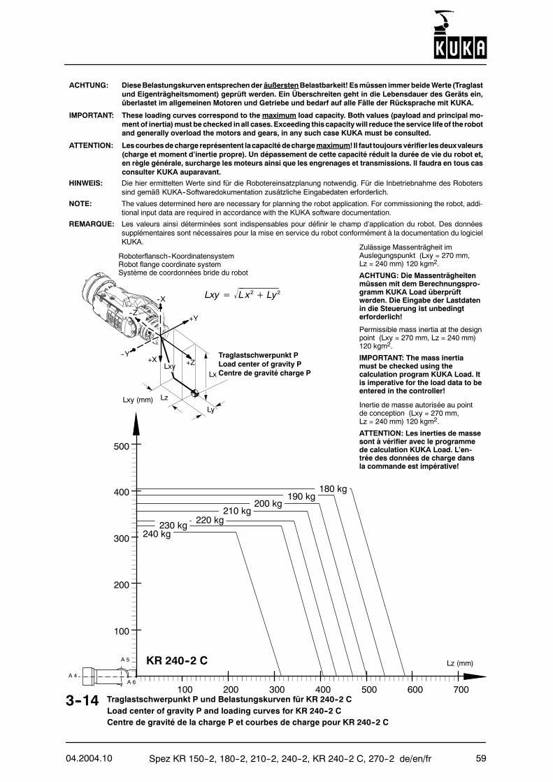
04.2004.10 Spez KR 150--2, 180--2, 210--2, 240--2, KR 240--2 C, 270--2 de/en/fr 59
HINWEIS: Die hier ermittelten Werte sind für die Robotereinsatzplanung notwendig. Für die Inbetriebnahme des Roboterssind gemäß KUKA--Softwaredokumentation zusätzliche Eingabedaten erforderlich.
NOTE: The values determined here are necessary for planning the robot application. For commissioning the robot, addi-tional input data are required in accordance with the KUKA software documentation.
REMARQUE: Les valeurs ainsi déterminées sont indispensables pour définir le champ d’application du robot. Des donnéessupplémentaires sont nécessaires pour la mise en service du robot conformément à la documentation du logicielKUKA.
3--14 Traglastschwerpunkt P und Belastungskurven für KR 240--2 CLoad center of gravity P and loading curves for KR 240--2 CCentre de gravité de la charge P et courbes de charge pour KR 240--2 C
ACHTUNG: DieseBelastungskurvenentsprechender äußerstenBelastbarkeit! Esmüssen immerbeideWerte (Traglastund Eigenträgheitsmoment) geprüft werden. Ein Überschreiten geht in die Lebensdauer des Geräts ein,überlastet im allgemeinen Motoren und Getriebe und bedarf auf alle Fälle der Rücksprache mit KUKA.
IMPORTANT: These loading curves correspond to the maximum load capacity. Both values (payload and principal mo-ment of inertia)must be checked inall cases.Exceeding thiscapacitywill reduce theservice lifeof the robotand generally overload the motors and gears, in any such case KUKA must be consulted.
ATTENTION: Lescourbesdechargereprésentent lacapacitédechargemaximum!Il faut toujoursvérifier lesdeuxvaleurs(charge et moment d’inertie propre). Un dépassement de cette capacité réduit la durée de vie du robot et,en règle générale, surcharge les moteurs ainsi que les engrenages et transmissions. Il faudra en tous casconsulter KUKA auparavant.
Roboterflansch--KoordinatensystemRobot flange coordinate systemSystème de coordonnées bride du robot
--X
Lz
Lx
Ly
+X--Y
+Y
+Z
--Z
Traglastschwerpunkt PLoad center of gravity PCentre de gravité charge P
Lxy= L x2+ Ly2
Lxy
Zulässige Massenträgheit imAuslegungspunkt (Lxy = 270 mm,Lz = 240 mm) 120 kgm2.
ACHTUNG: Die Massenträgheitenmüssen mit dem Berechnungspro-gramm KUKA Load überprüftwerden. Die Eingabe der Lastdatenin die Steuerung ist unbedingterforderlich!
Permissible mass inertia at the designpoint (Lxy = 270 mm, Lz = 240 mm)120 kgm2.
IMPORTANT: The mass inertiamust be checked using thecalculation program KUKA Load. Itis imperative for the load data to beentered in the controller!
Inertie de masse autorisée au pointde conception (Lxy = 270 mm,Lz = 240 mm) 120 kgm2.
ATTENTION: Les inerties de massesont à vérifier avec le programmede calculation KUKA Load. L’en-trée des données de charge dansla commande est impérative!
Lxy (mm)
100 200 300 400 500 700600
100
200
300
400
Lz (mm)
500
A 4
A 5
A 6
KR 240--2 C
240 kg230 kg 220 kg
210 kg200 kg
190 kg180 kg
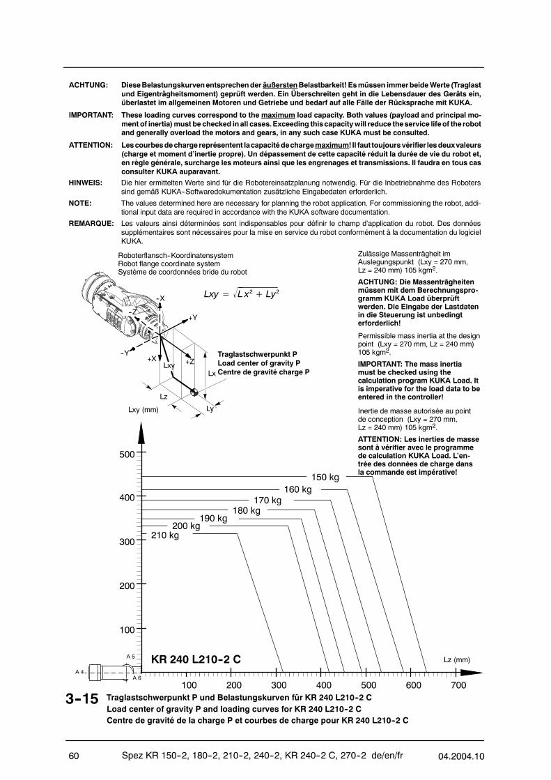
Spez KR 150--2, 180--2, 210--2, 240--2, KR 240--2 C, 270--2 de/en/fr 04.2004.1060
HINWEIS: Die hier ermittelten Werte sind für die Robotereinsatzplanung notwendig. Für die Inbetriebnahme des Roboterssind gemäß KUKA--Softwaredokumentation zusätzliche Eingabedaten erforderlich.
NOTE: The values determined here are necessary for planning the robot application. For commissioning the robot, addi-tional input data are required in accordance with the KUKA software documentation.
REMARQUE: Les valeurs ainsi déterminées sont indispensables pour définir le champ d’application du robot. Des donnéessupplémentaires sont nécessaires pour la mise en service du robot conformément à la documentation du logicielKUKA.
3--15 Traglastschwerpunkt P und Belastungskurven für KR 240 L210--2 CLoad center of gravity P and loading curves for KR 240 L210--2 CCentre de gravité de la charge P et courbes de charge pour KR 240 L210--2 C
ACHTUNG: DieseBelastungskurvenentsprechender äußerstenBelastbarkeit! Esmüssen immerbeideWerte (Traglastund Eigenträgheitsmoment) geprüft werden. Ein Überschreiten geht in die Lebensdauer des Geräts ein,überlastet im allgemeinen Motoren und Getriebe und bedarf auf alle Fälle der Rücksprache mit KUKA.
IMPORTANT: These loading curves correspond to the maximum load capacity. Both values (payload and principal mo-ment of inertia)must be checked inall cases.Exceeding thiscapacitywill reduce theservice lifeof the robotand generally overload the motors and gears, in any such case KUKA must be consulted.
ATTENTION: Lescourbesdechargereprésentent lacapacitédechargemaximum!Il faut toujoursvérifier lesdeuxvaleurs(charge et moment d’inertie propre). Un dépassement de cette capacité réduit la durée de vie du robot et,en règle générale, surcharge les moteurs ainsi que les engrenages et transmissions. Il faudra en tous casconsulter KUKA auparavant.
Roboterflansch--KoordinatensystemRobot flange coordinate systemSystème de coordonnées bride du robot
--X
Lz
Lx
Ly
+X--Y
+Y
+Z
--Z
Traglastschwerpunkt PLoad center of gravity PCentre de gravité charge P
Lxy= L x2+ Ly2
Lxy
Zulässige Massenträgheit imAuslegungspunkt (Lxy = 270 mm,Lz = 240 mm) 105 kgm2.
ACHTUNG: Die Massenträgheitenmüssen mit dem Berechnungspro-gramm KUKA Load überprüftwerden. Die Eingabe der Lastdatenin die Steuerung ist unbedingterforderlich!
Permissible mass inertia at the designpoint (Lxy = 270 mm, Lz = 240 mm)105 kgm2.
IMPORTANT: The mass inertiamust be checked using thecalculation program KUKA Load. Itis imperative for the load data to beentered in the controller!
Inertie de masse autorisée au pointde conception (Lxy = 270 mm,Lz = 240 mm) 105 kgm2.
ATTENTION: Les inerties de massesont à vérifier avec le programmede calculation KUKA Load. L’en-trée des données de charge dansla commande est impérative!
Lxy (mm)
100 200 300 400 500 700600
100
200
300
400
Lz (mm)
500
A 4
A 5
A 6
KR 240 L210--2 C
210 kg200 kg
190 kg180 kg
170 kg160 kg
150 kg
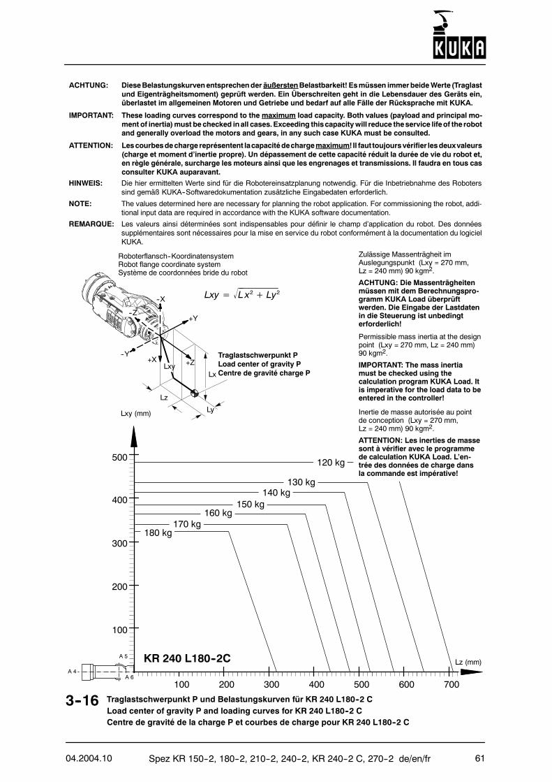
04.2004.10 Spez KR 150--2, 180--2, 210--2, 240--2, KR 240--2 C, 270--2 de/en/fr 61
HINWEIS: Die hier ermittelten Werte sind für die Robotereinsatzplanung notwendig. Für die Inbetriebnahme des Roboterssind gemäß KUKA--Softwaredokumentation zusätzliche Eingabedaten erforderlich.
NOTE: The values determined here are necessary for planning the robot application. For commissioning the robot, addi-tional input data are required in accordance with the KUKA software documentation.
REMARQUE: Les valeurs ainsi déterminées sont indispensables pour définir le champ d’application du robot. Des donnéessupplémentaires sont nécessaires pour la mise en service du robot conformément à la documentation du logicielKUKA.
3--16 Traglastschwerpunkt P und Belastungskurven für KR 240 L180--2 CLoad center of gravity P and loading curves for KR 240 L180--2 CCentre de gravité de la charge P et courbes de charge pour KR 240 L180--2 C
ACHTUNG: DieseBelastungskurvenentsprechender äußerstenBelastbarkeit! Esmüssen immerbeideWerte (Traglastund Eigenträgheitsmoment) geprüft werden. Ein Überschreiten geht in die Lebensdauer des Geräts ein,überlastet im allgemeinen Motoren und Getriebe und bedarf auf alle Fälle der Rücksprache mit KUKA.
IMPORTANT: These loading curves correspond to the maximum load capacity. Both values (payload and principal mo-ment of inertia)must be checked inall cases.Exceeding thiscapacitywill reduce theservice lifeof the robotand generally overload the motors and gears, in any such case KUKA must be consulted.
ATTENTION: Lescourbesdechargereprésentent lacapacitédechargemaximum!Il faut toujoursvérifier lesdeuxvaleurs(charge et moment d’inertie propre). Un dépassement de cette capacité réduit la durée de vie du robot et,en règle générale, surcharge les moteurs ainsi que les engrenages et transmissions. Il faudra en tous casconsulter KUKA auparavant.
Roboterflansch--KoordinatensystemRobot flange coordinate systemSystème de coordonnées bride du robot
--X
Lz
Lx
Ly
+X--Y
+Y
+Z
--Z
Traglastschwerpunkt PLoad center of gravity PCentre de gravité charge P
Lxy= L x2+ Ly2
Lxy
180 kg170 kg
160 kg150 kg
140 kg130 kg
120 kg
Lxy (mm)
100 200 300 400 500 700600
100
200
300
400
Lz (mm)
500
A 4
A 5
A 6
KR 240 L180--2C
Zulässige Massenträgheit imAuslegungspunkt (Lxy = 270 mm,Lz = 240 mm) 90 kgm2.
ACHTUNG: Die Massenträgheitenmüssen mit dem Berechnungspro-gramm KUKA Load überprüftwerden. Die Eingabe der Lastdatenin die Steuerung ist unbedingterforderlich!
Permissible mass inertia at the designpoint (Lxy = 270 mm, Lz = 240 mm)90 kgm2.
IMPORTANT: The mass inertiamust be checked using thecalculation program KUKA Load. Itis imperative for the load data to beentered in the controller!
Inertie de masse autorisée au pointde conception (Lxy = 270 mm,Lz = 240 mm) 90 kgm2.
ATTENTION: Les inerties de massesont à vérifier avec le programmede calculation KUKA Load. L’en-trée des données de charge dansla commande est impérative!
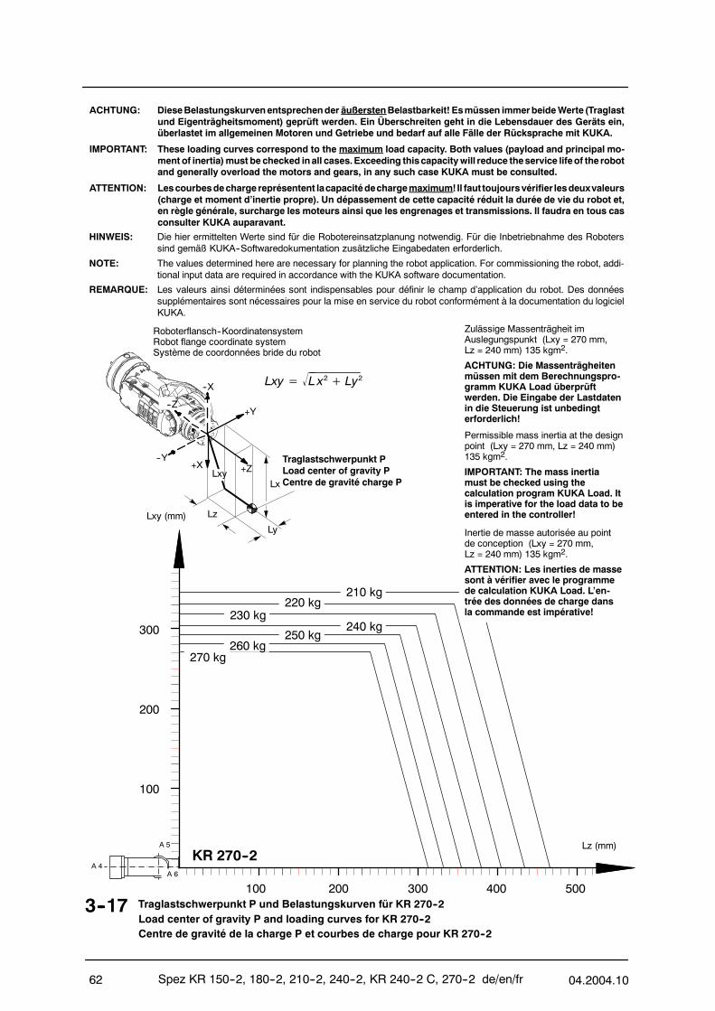
Spez KR 150--2, 180--2, 210--2, 240--2, KR 240--2 C, 270--2 de/en/fr 04.2004.1062
HINWEIS: Die hier ermittelten Werte sind für die Robotereinsatzplanung notwendig. Für die Inbetriebnahme des Roboterssind gemäß KUKA--Softwaredokumentation zusätzliche Eingabedaten erforderlich.
NOTE: The values determined here are necessary for planning the robot application. For commissioning the robot, addi-tional input data are required in accordance with the KUKA software documentation.
REMARQUE: Les valeurs ainsi déterminées sont indispensables pour définir le champ d’application du robot. Des donnéessupplémentaires sont nécessaires pour la mise en service du robot conformément à la documentation du logicielKUKA.
3--17 Traglastschwerpunkt P und Belastungskurven für KR 270--2Load center of gravity P and loading curves for KR 270--2Centre de gravité de la charge P et courbes de charge pour KR 270--2
ACHTUNG: DieseBelastungskurvenentsprechender äußerstenBelastbarkeit! Esmüssen immerbeideWerte (Traglastund Eigenträgheitsmoment) geprüft werden. Ein Überschreiten geht in die Lebensdauer des Geräts ein,überlastet im allgemeinen Motoren und Getriebe und bedarf auf alle Fälle der Rücksprache mit KUKA.
IMPORTANT: These loading curves correspond to the maximum load capacity. Both values (payload and principal mo-ment of inertia)must be checked inall cases.Exceeding thiscapacitywill reduce theservice lifeof the robotand generally overload the motors and gears, in any such case KUKA must be consulted.
ATTENTION: Lescourbesdechargereprésentent lacapacitédechargemaximum!Il faut toujoursvérifier lesdeuxvaleurs(charge et moment d’inertie propre). Un dépassement de cette capacité réduit la durée de vie du robot et,en règle générale, surcharge les moteurs ainsi que les engrenages et transmissions. Il faudra en tous casconsulter KUKA auparavant.
Roboterflansch--KoordinatensystemRobot flange coordinate systemSystème de coordonnées bride du robot
--X
Lz
Lx
Ly
+X--Y
+Y
+Z
--Z
Traglastschwerpunkt PLoad center of gravity PCentre de gravité charge P
Lxy= L x2+ Ly2
Lxy
A 4
A 5
A 6
Lxy (mm)
100 200 300 400 500
100
200
300
Lz (mm)KR 270--2
250 kg
270 kg260 kg
240 kg230 kg
220 kg210 kg
Zulässige Massenträgheit imAuslegungspunkt (Lxy = 270 mm,Lz = 240 mm) 135 kgm2.
ACHTUNG: Die Massenträgheitenmüssen mit dem Berechnungspro-gramm KUKA Load überprüftwerden. Die Eingabe der Lastdatenin die Steuerung ist unbedingterforderlich!
Permissible mass inertia at the designpoint (Lxy = 270 mm, Lz = 240 mm)135 kgm2.
IMPORTANT: The mass inertiamust be checked using thecalculation program KUKA Load. Itis imperative for the load data to beentered in the controller!
Inertie de masse autorisée au pointde conception (Lxy = 270 mm,Lz = 240 mm) 135 kgm2.
ATTENTION: Les inerties de massesont à vérifier avec le programmede calculation KUKA Load. L’en-trée des données de charge dansla commande est impérative!
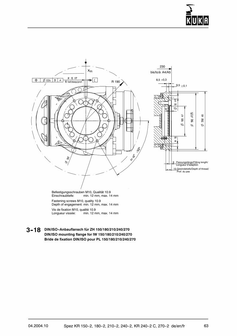
04.2004.10 Spez KR 150--2, 180--2, 210--2, 240--2, KR 240--2 C, 270--2 de/en/fr 63
3--18 DIN/ISO--Anbauflansch für ZH 150/180/210/240/270DIN/ISO mounting flange for IW 150/180/210/240/270Bride de fixation DIN/ISO pour PL 150/180/210/240/270
xm
R 190
230
8 Passungslänge/Fitting length/Longueur d’adaption
9,5 ¦0,1
8,5 +0,3
Befestigungsschrauben M10, Qualität 10.9Einschraubtiefe: min. 12 mm, max. 14 mm
Fastening screws M10, quality 10.9Depth of engagement: min. 12 mm, max. 14 mm
Vis de fixation M10, qualité 10.9Longueur vissée: min. 12 mm, max. 14 mm
bis/to/à A4/A5
15 Gewindetiefe/Depth of thread/Prof. du pas
tief/deep/prof.
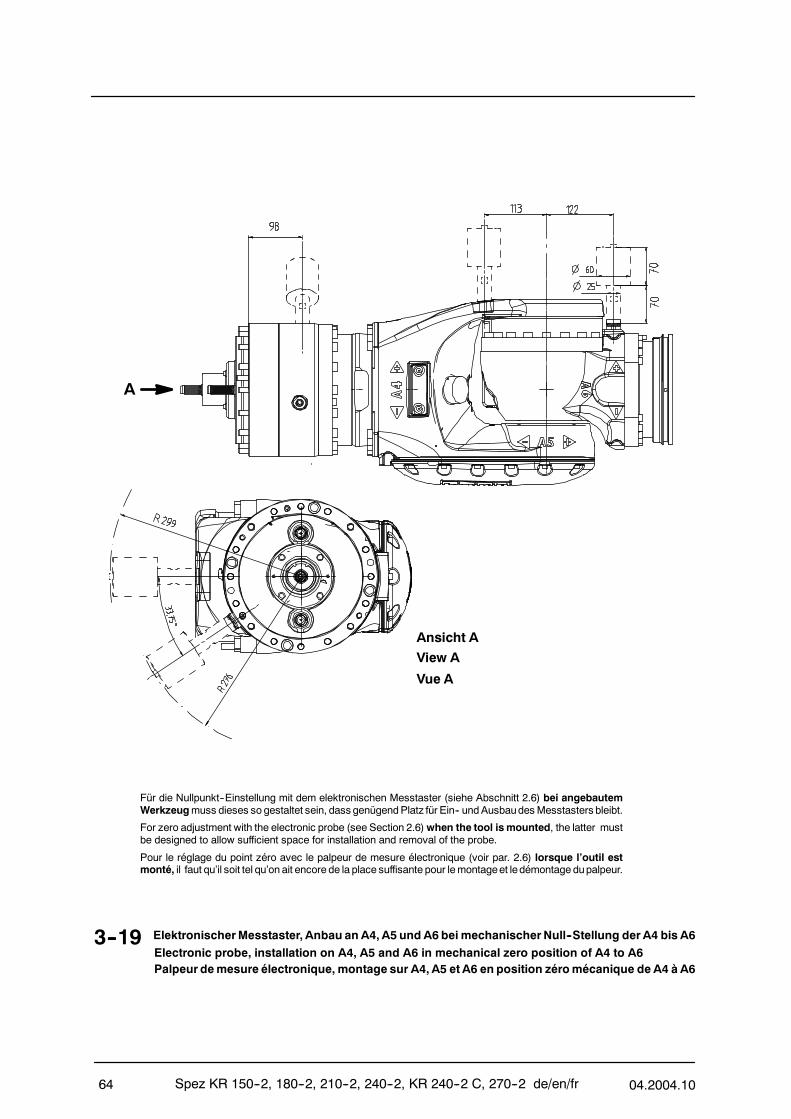
Spez KR 150--2, 180--2, 210--2, 240--2, KR 240--2 C, 270--2 de/en/fr 04.2004.1064
Für die Nullpunkt--Einstellung mit dem elektronischen Messtaster (siehe Abschnitt 2.6) bei angebautemWerkzeugmuss dieses so gestaltet sein, dass genügendPlatz für Ein-- undAusbaudesMesstasters bleibt.
For zero adjustment with the electronic probe (see Section 2.6)when the tool is mounted, the latter mustbe designed to allow sufficient space for installation and removal of the probe.
Pour le réglage du point zéro avec le palpeur de mesure électronique (voir par. 2.6) lorsque l’outil estmonté, il faut qu’il soit tel qu’on ait encore de la place suffisante pour lemontageet ledémontage dupalpeur.
A
Ansicht A
3--19 ElektronischerMesstaster, Anbau an A4, A5 und A6 bei mechanischerNull--Stellung derA4 bis A6Electronic probe, installation on A4, A5 and A6 in mechanical zero position of A4 to A6Palpeur demesure électronique, montage sur A4, A5 et A6 en position zéromécanique de A4 à A6
View A
Vue A
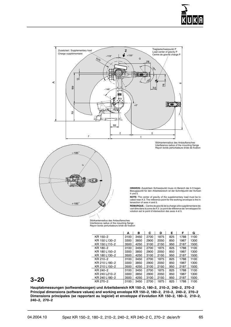
04.2004.10 Spez KR 150--2, 180--2, 210--2, 240--2, KR 240--2 C, 270--2 de/en/fr 65
3--20Hauptabmessungen (softwarebezogen) und Arbeitsbereich KR 150--2, 180--2, 210--2, 240--2, 270--2Principal dimensions (software values) and working envelope KR 150--2, 180--2, 210--2, 240--2, 270--2Dimensions principales (se rapportant au logiciel) et enveloppe d’évolution KR 150--2, 180--2, 210--2,240--2, 270--2
HINWEIS: Zusatzlast--Schwerpunkt muss im Bereich der A 3 liegen.Bezugspunkt für den Arbeitsbereich ist der Schnittpunkt der Achsen4 und 5.
NOTE: The center of gravity of the supplementary load must be lo-cated near A 3. The reference point for the working envelope is the in-tersection of axes 4 and 5.
REMARQUE.-- Centre de gravité de la charge utile supplémentaire de-vant être dans la zone deA 3. Le point de référence de l’envelopped’é-volution est le point d’intersection des axes 4 et 5.
A B C D E F GKR 150--2 3100 3450 2700 1875 825 1788 1100KR 150 L130--2 3300 3850 2900 2050 850 1987 1300KR 150 L110--2 3500 4250 3100 2150 950 2187 1500KR 180--2 3100 3450 2700 1875 825 1788 1100KR 180 L150--2 3300 3850 2900 2050 850 1987 1300KR 180 L130--2 3500 4250 3100 2150 950 2187 1500KR 210--2 3100 3450 2700 1875 825 1788 1100KR 210 L180--2 3300 3850 2900 2050 850 1987 1300KR 210 L150--2 3500 4250 3100 2150 950 2187 1500KR 240--2 3100 3450 2700 1875 825 1788 1100KR 240 L210--2 3300 3850 2900 2050 850 1987 1300KR 240 L180--2 3500 4250 3100 2150 950 2187 1500KR 270--2 3100 3450 2700 1875 825 1788 1100
G
Traglastschwerpunkt PLoad center of gravity PCentre de gravité charge P
Zusatzlast / Supplementary loadCharge supplémentaire
Z
--146°
+0°
--119° +155°
---185˚
+185˚
Störkantenradius des AnbauflanschesInterference radius of the mounting flangeRayon bords perturbateurs bride de fixation
A
Störkantenradius des AnbauflanschesInterference radius of the mounting flangeRayon bords perturbateurs bride de fixation
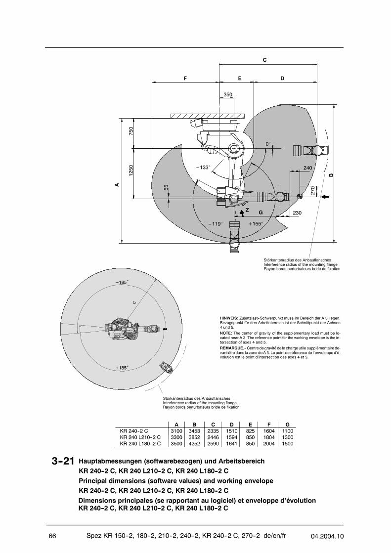
Spez KR 150--2, 180--2, 210--2, 240--2, KR 240--2 C, 270--2 de/en/fr 04.2004.1066
3--21 Hauptabmessungen (softwarebezogen) und ArbeitsbereichKR 240--2 C, KR 240 L210--2 C, KR 240 L180--2 C
Principal dimensions (software values) and working envelopeKR 240--2 C, KR 240 L210--2 C, KR 240 L180--2 C
Dimensions principales (se rapportant au logiciel) et enveloppe d’évolutionKR 240--2 C, KR 240 L210--2 C, KR 240 L180--2 C
HINWEIS: Zusatzlast--Schwerpunkt muss im Bereich der A 3 liegen.Bezugspunkt für den Arbeitsbereich ist der Schnittpunkt der Achsen4 und 5.
NOTE: The center of gravity of the supplementary load must be lo-cated near A 3. The reference point for the working envelope is the in-tersection of axes 4 and 5.
REMARQUE.-- Centre de gravité de la charge utile supplémentaire de-vant être dans la zone deA 3. Le point de référence de l’envelopped’é-volution est le point d’intersection des axes 4 et 5.
A B C D E F GKR 240--2 C 3100 3453 2335 1510 825 1604 1100KR 240 L210--2 C 3300 3852 2446 1594 850 1804 1300KR 240 L180--2 C 3500 4252 2590 1641 850 2004 1500
---185˚
+185˚
Störkantenradius des AnbauflanschesInterference radius of the mounting flangeRayon bords perturbateurs bride de fixation
Störkantenradius des AnbauflanschesInterference radius of the mounting flangeRayon bords perturbateurs bride de fixation
750
55
1250
230
240
270
B
350
---119°
---133°
+155°
0°
A
C
F E D
G
Z
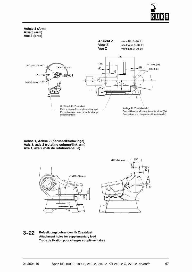
04.2004.10 Spez KR 150--2, 180--2, 210--2, 240--2, KR 240--2 C, 270--2 de/en/fr 67
Ansicht Z siehe Bild 3--20, 21
View Z see Figure 3--20, 21
Vue Z voir figure 3--20, 21
3--22 Befestigungsbohrungen für ZusatzlastAttachment holes for supplementary loadTrous de fixation pour charges supplémentaires
bis/to/jusqu’à --95°X = 125 mm
X = 100 mm
Auflage für Zusatzlast (2x)Support brackets for supplementary load (2x)Support pour la charge supplémentaire (2x)
Größtmaß für ZusatzlastMaximum size for supplementary loadEncombrement max. pour la chargesupplémentaire
bis/to/jusqu’à --120°
Achse 3 (Arm)Axis 3 (arm)Axe 3 (bras)
Achse 1, Achse 2 (Karussell/Schwinge)Axis 1, axis 2 (rotating column/link arm)Axe 1, axe 2 (bâti de rotation/épaule)
70
M12x24 (4x)
500
150
150
5°
315
149
80
M20x30 (4x)
M12x18 (4x)
M8x8 (2x)
X
380
40 40180
70
35
110
KUKA Automatisering+ Robots N.V.Centrum Zuid 1031B--3530 HouthalenTel.: +32 11 516160E--Mail: [email protected]
Robots industrielsH Robotspolyarticuléspourdeschargescomprisesentre3kget 500kg
H Unités linéaires
H Baies de commande
H Développement de logiciels
H Formation, service clients
KUKA Sistemas deAutomatización, S.A.Pol. Industrial Torrent de la PasteraCarrer del Bages s/nE--08800 Vilanova i la GeltrúTel.: +34 93 8142353E--Mail: [email protected]
KUKA Robotics Corp.22500 Key DriveClinton TownshipMichigan 48036 USATel.: +1 866 873--5852E--Mail: [email protected]
IndustrieroboterH Gelenkroboter für Traglastenvon 3 bis 500 kg
H Lineareinheiten
H Steuerungen
H Softwareentwicklung
H Schulung, Service
Anschriften -- Addresses -- Adresses
ProduktprogrammIndustrial robotsH Jointed--arm robots forpayloads from 3 kg to 500 kg
H Linear units
H Controllers
H Software development
H Training, service
KUKA Welding Systems+ Robot Ltd.Hereward Rise HalesowenUK--West Midlands B62 8AN GBTel.: +44 121 5850800E--Mail: [email protected]
KUKA Robot AutomationKorea Co. Ltd.4 Ba 806 Sihwa Ind. Complex,Sung--Gok Dong, Ansan City,Kyunggi Do, 425--110 KoreaTel.: +82 31 4969937E--Mail: [email protected]
Technische Daten und Abbildungen unverbindlichfür Lieferung. Änderungen vorbehalten.No liability accepted for errors or omissions.Caractéristiques techniques et figures à titre indicatifpour la livraison. Sous réserve de modifications techniques
Überreicht durchHanded over byRemis par
09/04
KUKA Roboter GmbHGlobal Sales CenterHery--Park 3000D--86368 GersthofenTel.: +49 821 4533--0Fax: +49 821 4533--1616E--Mail: [email protected]: http://www.kuka--roboter.de
KUKA Roboter Italia S.p.A.Via Pavia 9/a -- int.6I--10098 Rivoli (TO)Tel.: +39 011 9595013E--Mail: [email protected]
KUKA Roboter GmbH
Gamme de produitsProduct range
KUKA Svetsanläggningar+ Robotar ABA. Odhners gata 15S--42130 Västra FrölundaTel.: +46 31 7266200E--Mail: [email protected]
KUKA Roboter do Brasil Ltda.Rua Dom Feliciano N˚ 63Cidade Satélite, GuarulhosCEP 07224 240São Paulo, SP, BrasilTel.: +55 11 6413--4900E--Mail: [email protected]
KUKA de México S. de R.L. de C.V.Rio San Joaquin # 339, Local 5Col. Pensil SurC.P. México D.F. 11490Tel.: +52 55 52038407E--Mail: [email protected]
D
KUKA Roboter Schweiz AGRiedstrasse 7CH--8953 DietikonTel.: +41 17 449090E--Mail: [email protected]
I
MEX
ROK
S
UK
USA
B
BR
CH
E
AKUKA Roboter GmbHVertriebsbüro ÖsterreichRegensburger Strasse 9/1A--4020 LinzTel.: +43 732 784752E--Mail: [email protected]
KUKA Robotics Hungária Kft.2335 Taksony, Fö út 140HungáriaTel.: +36 24 501609E--Mail: [email protected]
H
KUKA Robot AutomationSdn Bhd South East AsiaRegional OfficeNo. 24, Jalan TPP 1/10Taman Industri Puchong47100 Puchong, Selangor, MalaysiaTel.: +60 3 8061--0613E--Mail: [email protected]
MAL
KUKA Sistemas de AutomatizaciónS.A.Urb. do Vale do Alecrim, Lote 115--BP--2950 PalmelaTel.: +3 51 21 2388083E--Mail: [email protected]
P
KUKA Automation Equipment(Shanghai) Co., Ltd.Part B, Ground Floor, No. 211Fu te Road (North)Waigaoqiao Free Trade ZoneShanghai 200 131, ChinaTel.: +86 21 58665139E--Mail: [email protected]
PRC
KUKA Automatisme+ Robotique SASTechvallée, 6 Avenue du ParcF--91140 Villebon S/YvetteTel.: +33 1 69316600E--Mail: [email protected]
F
KUKA Robot Automation (M)Sdn Bhd Thailand Officec/o Maccall System Co. Ltd.49/9--10 Soi Kingkaew 30,Kingkaew RoadT. Rachatheva, A. BangpliSamutprakarn, 10540 ThailandTel.: +66 2 7502737E--Mail: [email protected]
THA
KUKA Robot AutomationTaiwan Co. Ltd.136, Section 2,Huanjung East RoadJungli City, Taoyuan, Taiwan 320Tel.: +886 3 4371902E--Mail: [email protected]
TWN
KUKA Roboter GmbHNiederlassung NordVW--Werk, Halle 4,Eingang 22,Berliner RingD--38436 WolfsburgTel.: +49 5361 848481--0Fax: +49 5361 848481--26
KUKA Roboter GmbHNiederlassung WestDortmunder Straße 15D--57234 WilnsdorfTel.: +49 2739 4779--0Fax: +49 2739 4779--29E--Mail: [email protected]
NKUKA Svetsanläggningar+ Robotar AB Avd. NorwayHadelandsveien 2, Postbox 17NO--2801 Gjövik, NorwayTel.: +47 61 133422E--Mail: [email protected]