Serie Funcion RACCORDI A FUNZIONE In Line Adjustable ...
63
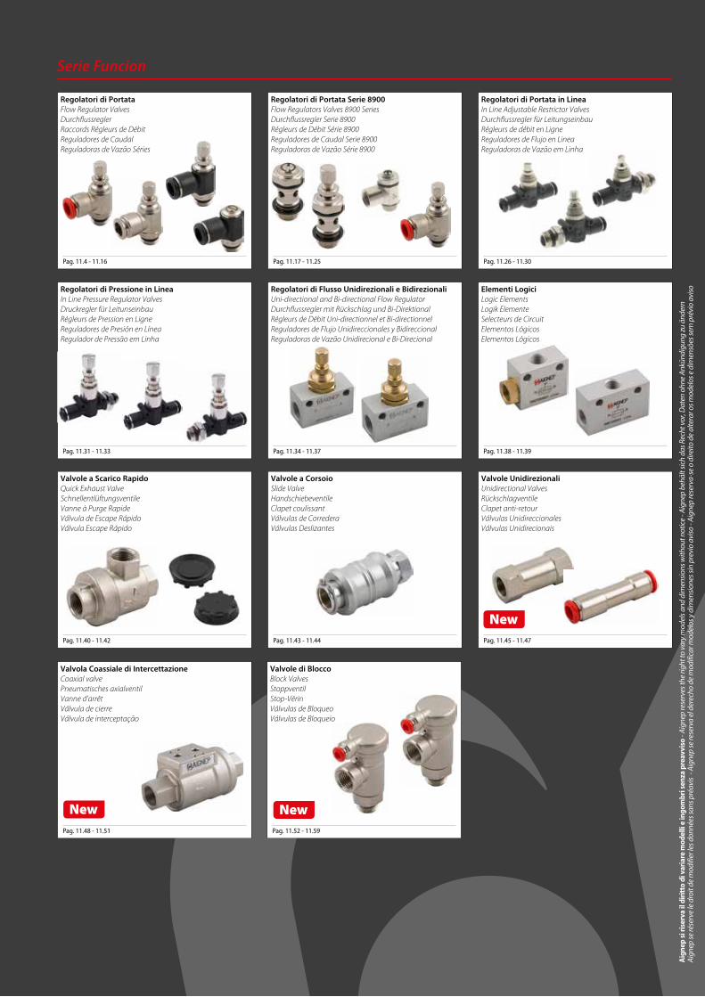
Aignep si riserva il diritto di variare modelli e ingombri senza preavviso - Aignep reserves the right to vary models and dimensions without notice - Aignep behält sich das Recht vor, Daten ohne Ankündigung zu ändern Aignep se réserve le droit de modifier les données sans préavis - Aignep se reserva el derecho de modificar modelos y dimensiones sin previo aviso - Aignep reserva-se o direito de alterar os modelos e dimensões sem prévio aviso Serie Funcion Pag. 11.4 - 11.16 Regolatori di Portata Flow Regulator Valves Durchflussregler Raccords Régleurs de Débit Reguladores de Caudal Reguladoras de Vazão Séries Pag. 11.31 - 11.33 Regolatori di Pressione in Linea In Line Pressure Regulator Valves Druckregler für Leitunseinbau Régleurs de Pression en Ligne Reguladores de Presión en Línea Regulador de Pressão em Linha Pag. 11.40 - 11.42 Valvole a Scarico Rapido Quick Exhaust Valve Schnellentlüftungsventile Vanne à Purge Rapide Válvula de Escape Rápido Válvula Escape Rápido Pag. 11.48 - 11.51 Pag. 11.52 - 11.59 Valvola Coassiale di Intercettazione Coaxial valve Pneumatisches axialventil Vanne d’arrêt Válvula de cierre Válvula de interceptação New Valvole di Blocco Block Valves Stoppventil Stop-Vérin Válvulas de Bloqueo Válvulas de Bloqueio New Pag. 11.17 - 11.25 Pag. 11.34 - 11.37 Pag. 11.43 - 11.44 Regolatori di Portata Serie 8900 Flow Regulators Valves 8900 Series Durchflussregler Serie 8900 Régleurs de Débit Série 8900 Reguladores de Caudal Serie 8900 Reguladoras de Vazão Série 8900 Regolatori di Flusso Unidirezionali e Bidirezionali Uni-directional and Bi-directional Flow Regulator Durchflussregler mit Rückschlag und Bi-Direktional Régleurs de Débit Uni-directionnel et Bi-directionnel Reguladores de Flujo Unidireccionales y Bidireccional Reguladoras de Vazão Unidirecional e Bi-Direcional Valvole a Corsoio Slide Valve Handschiebeventile Clapet coulissant Válvulas de Corredera Válvulas Deslizantes Pag. 11.26 - 11.30 Pag. 11.38 - 11.39 Pag. 11.45 - 11.47 Regolatori di Portata in Linea In Line Adjustable Restrictor Valves Durchflussregler für Leitungseinbau Régleurs de débit en Ligne Reguladores de Flujo en Linea Reguladoras de Vazão em Linha Elementi Logici Logic Elements Logik Elemente Selecteurs de Circuit Elementos Lógicos Elementos Lógicos Valvole Unidirezionali Unidirectional Valves Rückschlagventile Clapet anti-retour Válvulas Unidireccionales Válvulas Unidirecionais New
Transcript of Serie Funcion RACCORDI A FUNZIONE In Line Adjustable ...
Aig
nep
si ri
serv
a il
diri
tto
di v
aria
re m
odel
li e
ingo
mbr
i sen
za p
reav
viso
- Ai
gnep
rese
rves
the
right
to v
ary
mod
els a
nd d
imen
sion
s with
out n
otic
e - A
igne
p be
hält
sich
das
Rec
ht v
or, D
aten
ohn
e An
künd
igun
g zu
änd
ern
Ai
gnep
se ré
serv
e le
dro
it de
mod
ifier
les d
onné
es sa
ns p
réav
is -
Aig
nep
se re
serv
a el
der
echo
de
mod
ifica
r mod
elos
y d
imen
sion
es si
n pr
evio
avi
so -
Aign
ep re
serv
a-se
o d
ireito
de
alte
rar o
s mod
elos
e d
imen
sões
sem
pré
vio
avis
o
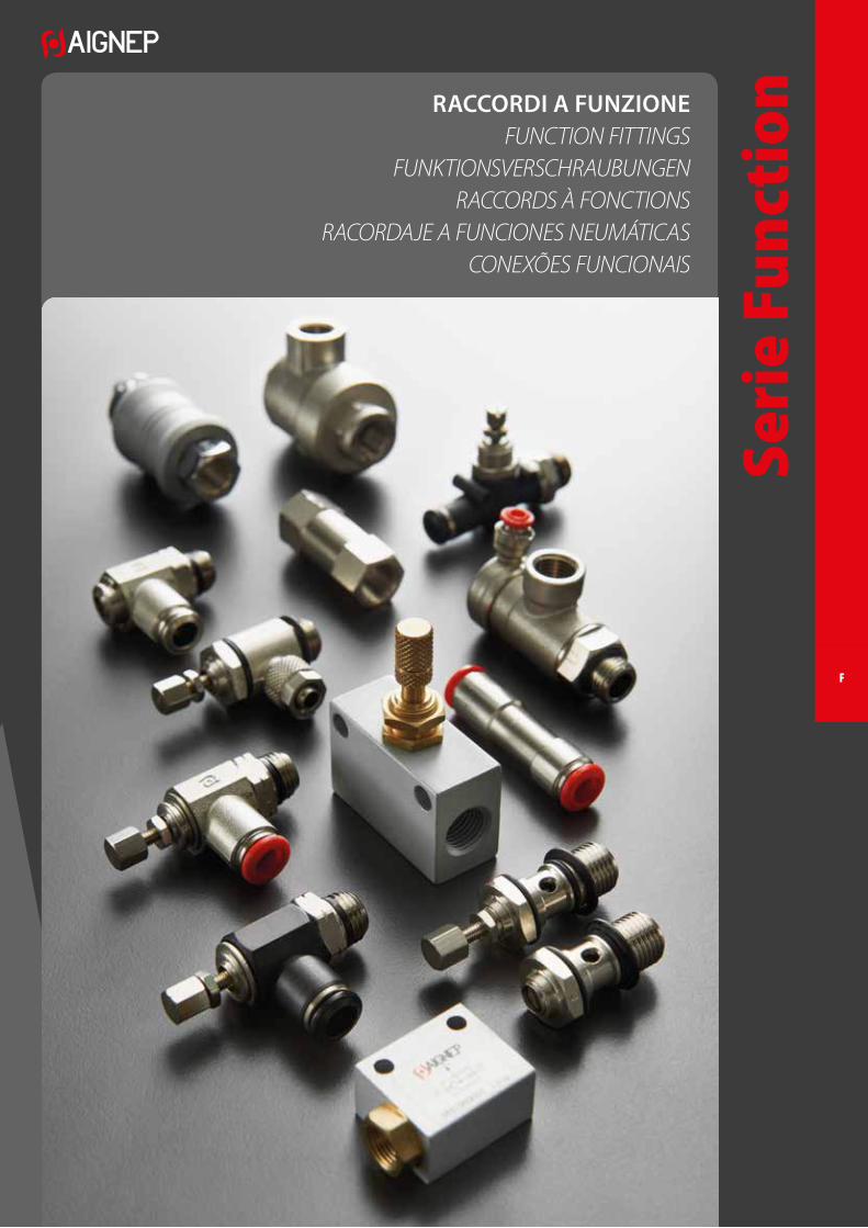
RACCORDI A FUNZIONEFUNCTION FITTINGS
FUNKTIONSVERSCHRAUBUNGENRACCORDS À FONCTIONS
RACORDAJE A FUNCIONES NEUMÁTICASCONEXÕES FUNCIONAIS
Serie Funcion
Pag. 11.4 - 11.16
Regolatori di PortataFlow Regulator ValvesDurchflussreglerRaccords Régleurs de DébitReguladores de CaudalReguladoras de Vazão Séries
Pag. 11.31 - 11.33
Regolatori di Pressione in LineaIn Line Pressure Regulator Valves Druckregler für LeitunseinbauRégleurs de Pression en LigneReguladores de Presión en LíneaRegulador de Pressão em Linha
Pag. 11.40 - 11.42
Valvole a Scarico RapidoQuick Exhaust ValveSchnellentlüftungsventileVanne à Purge RapideVálvula de Escape RápidoVálvula Escape Rápido
Pag. 11.48 - 11.51 Pag. 11.52 - 11.59
Valvola Coassiale di IntercettazioneCoaxial valve Pneumatisches axialventil Vanne d’arrêt Válvula de cierre Válvula de interceptação
New
Valvole di BloccoBlock ValvesStoppventilStop-VérinVálvulas de BloqueoVálvulas de Bloqueio
New
Pag. 11.17 - 11.25
Pag. 11.34 - 11.37
Pag. 11.43 - 11.44
Regolatori di Portata Serie 8900Flow Regulators Valves 8900 SeriesDurchflussregler Serie 8900Régleurs de Débit Série 8900Reguladores de Caudal Serie 8900Reguladoras de Vazão Série 8900
Regolatori di Flusso Unidirezionali e BidirezionaliUni-directional and Bi-directional Flow RegulatorDurchflussregler mit Rückschlag und Bi-DirektionalRégleurs de Débit Uni-directionnel et Bi-directionnelReguladores de Flujo Unidireccionales y BidireccionalReguladoras de Vazão Unidirecional e Bi-Direcional
Valvole a CorsoioSlide ValveHandschiebeventileClapet coulissantVálvulas de CorrederaVálvulas Deslizantes
Pag. 11.26 - 11.30
Pag. 11.38 - 11.39
Pag. 11.45 - 11.47
Regolatori di Portata in LineaIn Line Adjustable Restrictor Valves Durchflussregler für LeitungseinbauRégleurs de débit en LigneReguladores de Flujo en LineaReguladoras de Vazão em Linha
Elementi LogiciLogic Elements Logik ElementeSelecteurs de CircuitElementos Lógicos Elementos Lógicos
Valvole UnidirezionaliUnidirectional ValvesRückschlagventileClapet anti-retourVálvulas UnidireccionalesVálvulas Unidirecionais
New
Seri
e Fu
ncti
onRACCORDI A FUNZIONEFUNCTION FITTINGS
FUNKTIONSVERSCHRAUBUNGENRACCORDS À FONCTIONS
RACORDAJE A FUNCIONES NEUMÁTICASCONEXÕES FUNCIONAIS
F
11.3
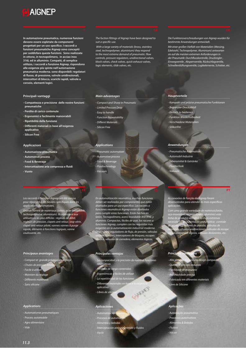
In automazione pneumatica, numerose funzioni devono essere espletate da componenti progettati per un uso specifico. I raccordi a funzioni pneumatiche Aignep sono concepiti per soddisfare queste funzioni. Sono realizzate in ottone, in tecnopolimero, in acciao inox 316L ed in alluminio. Compatti, di semplice utilizzo, i raccordi a funzione Aignep, rispondono alle esigenze più spinte nell’automazione pneumatica moderna. sono disponibili: regolatori di flusso, di pressione, valvole unidirezionali, intercettori di blocco, scarichi rapidi, valvole a corsoio, elementi logici.
Principali vantaggi
- Compattezza e precisione delle nostre funzioni pneumatiche
- Perdite di carico contenute
- Ergonomici e facilmente manovrabili
- Ripetibilità della funzione
- Differenti materiali in base all’esigenza applicativa
- Silicon Free
Applicazioni
- Automazione pneumatica
- Automotive process
- Food & Beverage
- Intercettazione aria compressa e fluidi
- Vuoto
Les raccords à fonction Aignep ont été conçus pour répondre à des besoins spécifiques dans les applications automatisées.
Grande variété de matériaux (laiton, acier inoxydable, technopolymère, aluminium). Ils répondent aux utilisations les plus difficles : régleurs de débit, régleurs de pression, clapets anti retour, stop vérin, clapet anti retour piloté, vannes vannes à purge rapide, éléments à fonctions logiques, vanne coulissante, etc.
Principaux avantages
- Compact et grande précision de réglage
- Chutes de pression limitées
- Facile à utiliser
- Maintien du réglage
- Différents matériaux
- Sans silicone
Applications
- Automatismes pneumatiques
- Process automobile
- Agro alimentaire
- Vide
IT
FR
The fuction fittings of Aignep have been designed to suit a specific use.
With a large variety of materials (brass, stainless steel, technopolymer, aluminium) they respond to the most estreme demand of pneumatic: flow controls, pressure regulators, unidirectional valves, block valves, check valves, quick exhaust valves, logic elements, slide valves, etc.
Main advantages
- Compact and Sharp in Pneumatic
- Limited Pressure Drop
- Easy to handle
- Function Repeatability
- Differnt Materials
- Silicon Free
Applications
- Pneumatic automation
- Automotive process
- Food & Beverage
- Fluidtechnology
- Vacuum
En automatización neumática, muchas funciones deben ser realizadas por componentes que están diseñados para un uso específico. Los racores a funciones neumáticas Aignep están diseñados para cumplir estas funciones. Están hechas en latón, Tecnopolímero, acero inoxidable AISI 316L y aluminio. Compactas, fáciles de usar, los racores a funciones Aignep, cumplen con los requisitos más exigentes en la automatización industrial moderna. Disponibles: reguladores de flujo, de presión, válvulas unidireccionales, interceptores de bloqueo, escapes rápidos, válvulas de corredera, elementos lógicos.
Principales ventajas
- La compacidad y la precisión de nuestras funciones neumáticas
- Pérdidas de carga contenidas
- Ergonómicas y fáciles de utilizar
- La repetitividad de las funciones
- Diferentes materiales en base a la exigencia aplicativa
- Libres de silicona
Aplicaciones
- Automatización neumática
- Procesos de automoción
- Alimentos y bebidas
- Interceptación aire comprimido y fluidos
- Vacío
GB
ES
Die Funktionsverschraubungen von Aignep wurden für bestimmte Anwendungen entwickelt.
Mit einer großen Vielfalt von Materialien (Messing, Edelstahl, Technopolymer, Aluminium) antworten sie auf die meisten extremen Anforderungen in der Pneumatik: Durchflusskontrolle, Druckregler , Einwegventile , Absperrventile, Rückschlagventile, Schnellentlüftungsventile, Logikelemente, Schieber, etc.
Hauptvorteile
- Kompakt und präzise pneumatische Funktionen
- Begrenzter Druckabfall
- Einfach zu bedienen
- Funktion Wiederholbarkeit
- Verschiedene Materialien
- Silikonfrei
Anwendungen
- Pneumatische Automation
- Automobil-Industrie
- Lebensmittel & Getränke
- Fluidtechnik
- Vakuum
As conexões de função da Aignep foram desenvolvidas para atender às mais específicas aplicações.
Com uma grande variedade de mateirais(latão, aço-inoxidável, tecnopolímero, alumínio) esta linha de produtos atendem às mais extremas necesidades da automação pneumática: controle de vazão,reguladores de pressão, válvulas de retenção, válvulas unidirecionais, válvulas de escape rápido,elementos lógicos, válvulas deslizantes, etc.
Principais vantagens
- Alta precisão funcional e design compacto
- Queda de pressão reduzida
- Facilidade de manuseio
- Repetibilidade precisa
- Fabricada em diferentes materiais
- Livre de Silicone
Aplicações
- Automação pneumática
- Processos automotivos
- Alimentos & Bebidas
- Fluidos
- Vácuo
DE
PT
11.4
Serie Function
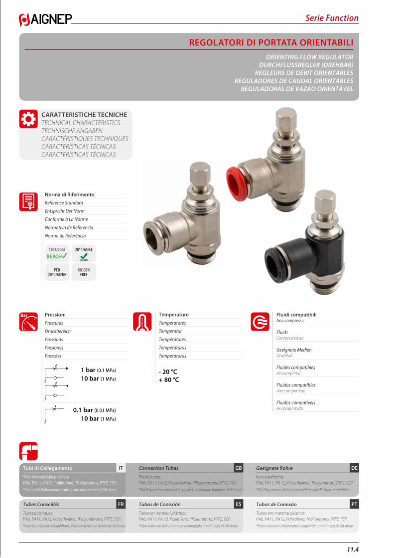
REGOLATORI DI PORTATA ORIENTABILIORIENTING FLOW REGULATOR
DURCHFLUSSREGLER (DREHBAR) RÉGLEURS DE DÉBIT ORIENTABLES
REGULADORES DE CAUDAL ORIENTABLESREGULADORAS DE VAZÃO ORIENTÁVEL
CARATTERISTICHE TECNICHE TECHNICAL CHARACTERISTICS TECHNISCHE ANGABEN CARACTÉRISTIQUES TECHNIQUES CARACTERÍSTICAS TÉCNICAS CARACTERÍSTICAS TÉCNICAS
1 bar (0.1 MPa)
10 bar (1 MPa)
0.1 bar (0.01 MPa)
10 bar (1 MPa)
Fluidi compatibili Aria compressa
Fluids Compressed air
Geeignete Medien Druckluft
Fluides compatibles Air comprimé
Fluidos compatibles Aire comprimido
Fluidos compatíveis Ar comprimido
Pressioni
Pressures
Druckbereich
Pressions
Presiones
Pressões
Bar
PTESFR
DEGBITTubi di Collegamento
Tubi in materiale plastico:PA6, PA11, PA12, Polietilene, *Poliuretano, PTFE, FEP.
*Per tubi in Poliuretano é consigliata una durezza di 98 shore.
Tubes Conseillés
Tubes plastiques:PA6, PA11, PA12, Polyéthylène, *Polyuréthane, PTFE, FEP.
*Pour les tubes en polyuréthane, il est conseillé une dureté de 98 Shore.
Connection Tubes
Plastic tubes:PA6, PA11, PA12, Polyethylene, *Polyurethane, PTFE, FEP.
*For Polyurethane hoses it is required a minimum hardness of 98 shore.
Tubos de Conexión
Tubos en material plástico:PA6, PA11, PA 12, Polietileno, *Poliuretano, PTFE, FEP.
*Para tubos en poliuretano es aconsejada una dureza de 98 shore.
Geeignete Rohre
Kunststoffrohre:PA6, PA11, PA 12, Polyethylene, *Polyurethan, PTFE, FEP.
*Für Polyurethan Rohre ist eine Härte von 98 Shore empfohlen.
Tubos de Conexão
Tubos em material plástico:PA6, PA11, PA12, Polietileno, *Poliuretano, PTFE, FEP.
*Para tubos em Poliuretano é requerida uma dureza de 98 shore.
- 20 °C+ 80 °C
Temperature
Temperatures
Temperatur
Températures
Temperaturas
Temperaturas
Norma di Riferimento
Reference Standard
Entspricht Der Norm
Conforme à La Norme
Normativa de Referencia
Norma de Referência
1907/2006 2011/65/CE
PED 2014/68/UE
SILICON FREE
11.5
Serie Function
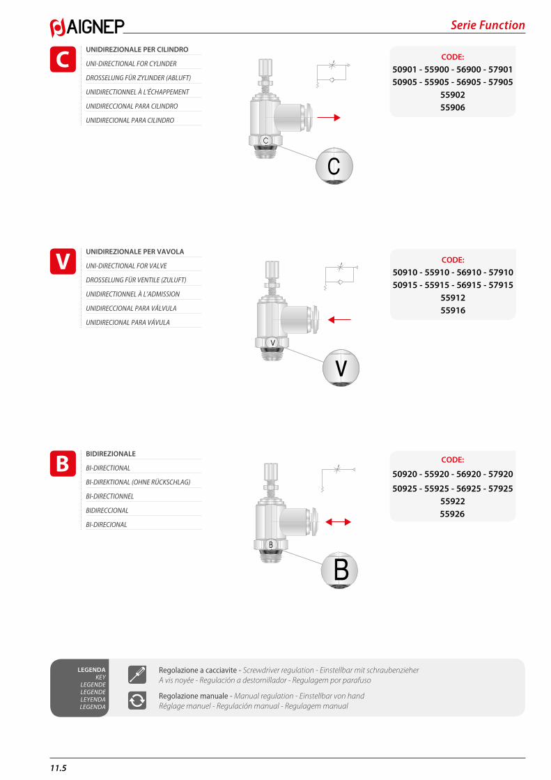
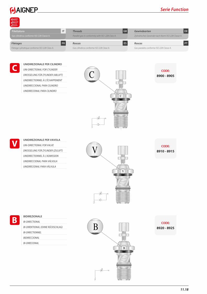
UNIDIREZIONALE PER CILINDRO
UNI-DIRECTIONAL FOR CYLINDER
DROSSELUNG FÜR ZYLINDER (ABLUFT)
UNIDIRECTIONNEL À L’ÉCHAPPEMENT
UNIDIRECCIONAL PARA CILINDRO
UNIDIRECIONAL PARA CILINDRO
CC
v BBv
CODE: 50901 - 55900 - 56900 - 5790150905 - 55905 - 56905 - 57905
5590255906
UNIDIREZIONALE PER VAVOLA
UNI-DIRECTIONAL FOR VALVE
DROSSELUNG FÜR VENTILE (ZULUFT)
UNIDIRECTIONNEL À L’ADMISSION
UNIDIRECCIONAL PARA VÁLVULA
UNIDIRECIONAL PARA VÁVULA
CC
v BBv
CODE: 50910 - 55910 - 56910 - 5791050915 - 55915 - 56915 - 57915
5591255916
BIDIREZIONALE
BI-DIRECTIONAL
BI-DIREKTIONAL (OHNE RÜCKSCHLAG)
BI-DIRECTIONNEL
BIDIRECCIONAL
BI-DIRECIONAL
CC
v BBv
CODE:
50920 - 55920 - 56920 - 57920
50925 - 55925 - 56925 - 579255592255926
LEGENDA KEY
LEGENDE LEGENDE LEYENDA LEGENDA
Regolazione a cacciavite - Screwdriver regulation - Einstellbar mit schraubenzieher A vis noyée - Regulación a destornillador - Regulagem por parafuso
Regolazione manuale - Manual regulation - Einstellbar von hand Réglage manuel - Regulación manual - Regulagem manual
11.6
Serie Function
DEGBITFilettatura
Filettatura “UNIVERSAL SHORT”.Metrica conforme ISO R/262.Gas cilindrica conforme ISO 228 Classe A.
Threads
”UNIVERSAL SHORT” Threads.Metric in conformity with ISO R/262.Parallel gas in conformity with ISO 228 Class A.
Gewindearten
Gewinde “UNIVERSAL SHORT”.Metrisches Gewinde nach Norm ISO R/262.Zylindrisches Gewinde nach Norm ISO 228 Classe A.
PTESFRFiletages
Filetage “UNIVERSAL SHORT”.Filetage métrique conforme ISO R/262.Filetage cylindrique conforme ISO 228 Class A.
Roscas
Rosca “UNIVERSAL SHORT”.Métrica conforme ISO R/262.Gas cilíndrica conforme ISO 228 Clase A.
Roscas
Rosca “UNIVERSAL SHORT”.Métrica conforme ISO R/262.Gas paralela conforme ISO 228 Classe A.
DEGB
NPTNPTF
ConicaTaperedKonischConiqueCónicaCônica
ISO 7BSPP
CilindricaParallellZylindrischCylindriqueCilíndricaParalela
ISO 7BSPT
PT
ConicaTaperedKonischConiqueCónicaCônica
ISO 228BSPPF
CilindricaParallellZylindrischCylindriqueCilíndricaParalela
InclinateInclinedGeneigtInclinéInclinadaInclinadas
ConcaveConcaveKonkavConcaveCóncavaCôncavas
ConvesseConvexKonvexConvexeConvexaConvexas
IT
PTESFR
PTESFR
DEGBIT“UNIVERSAL SHORT”
La filettatura conica “UNIVERSAL SHORT” è progettata per soddisfare le seguenti caratteristiche: • ridurre la lunghezza d’ingombro; • ridurre la chiave rispetto ad alcuni regolatori con
filettature cilindriche; • consentire l’accoppiamento con diversi standard
di fillettature femmina sia coniche che cilindriche.
“UNIVERSAL SHORT”
Le filetage conique “UNIVERSAL SHORT” a été conçu pour satisfaire les exigences suivantes: • réduire la longueur d’encombrement; • réduire les dimensions hexagonales par rapport au
filetage cylindrique; • permettre le montage avec divers taraudages
standards soit coniques soit cylindriques.
“UNIVERSAL SHORT”
The “UNIVERSAL SHORT” taper thread has been designed to offer the following advantages to the users: • reduced overall lenght; • smaller hex dimensions compared to the parallel
threads; • to allow the assembly with different female threads
both taper as well as parallel.
“UNIVERSAL SHORT”
La rosca cónica “UNIVERSAL SHORT” ha sido proyectada para satisfacer las siguientes características: • reducir la longitud; • reducir la llave respecto a algunos reguladores con
rosca cilíndrica; • consentir el acoplamiento con diferentes standard de
roscas hembra sean cónicas o cilíndricas.
“UNIVERSAL SHORT”
Das konische Gewinde “UNIVERSAL SHORT” ist so konzipiert, dass folgende Vorteile erzielt werden: • Reduzierung der Länge des Gewindes - kürzere
Montagezeit; • Reduzierung der Schlüsselweite im Vergleich von
Durchflussrecler mit zylindrischen Gewinden - geringerer Lochabstand
• Ermöglicht den Einsatz in verschiedene Gewindearten, sowie in konische- und zylindrische Innengewinde.
“UNIVERSAL SHORT”
A rosca cônica “UNIVERSAL SHORT” é projetada para satisfazer às sequintes características: • reduzir o comprimento da conexão; • reduzir o dimensional com relação às roscas
paralelas; • permitir o acoplamento da conexão a diferentes tipos
de rosca fêmea, sejam elas cônicas ou paralelas.
Consentire una completa tenuta anche su superfici non perfettamente piane, concave, convesse o inclinate, con diversi smussi o raggi.
Pour permettre une parfaite étanchéité même sur des surfaces non planes, concaves, convexes ou inclinées et avec différents chanfreins ou rayons.
To ensure the right tightening also with surfaces not perfectly flat, without spot-facing, concave convex and with different kinds of chamfers or radius.
Consentir una completa estanqueidad incluso en superficies no perfectamente planas, cóncavas,convexas o inclinadas, con diferentes ángulos o radios.
Eine vollständige Abdichtung ist auch auf unebenen Flächen, wie geneigt, konkav oder konvex und mit unterschiedlichen Radien oder Fasen gewährleistet.
Permite um aperto correto em superfícies não perfeitamente planas, côncavas, convexas ou inclinadas, com diferentes chanfros ou raios.
UNIVERSAL SHORT
UNIVERSAL SHORT
Serie Function
11.7
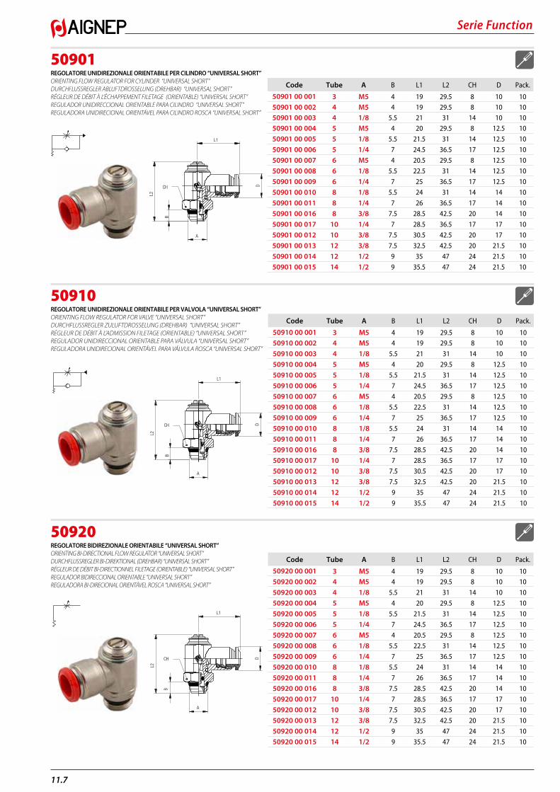
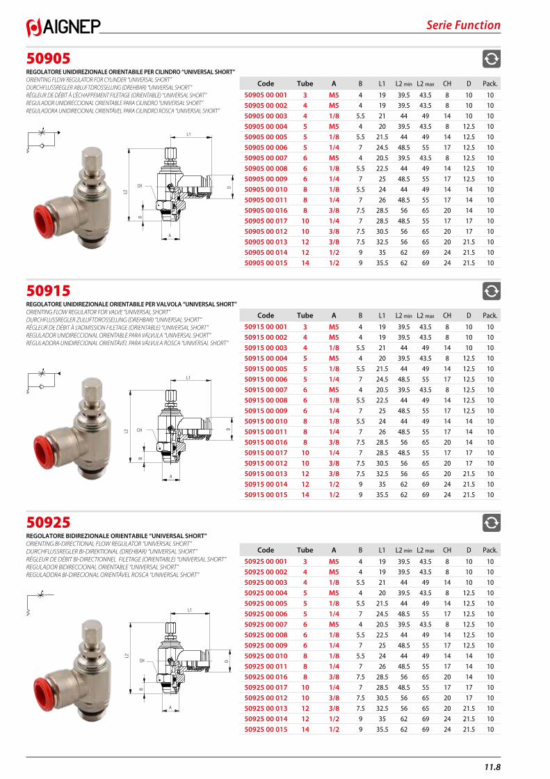
50901REGOLATORE UNIDIREZIONALE ORIENTABILE PER CILINDRO “UNIVERSAL SHORT” ORIENTING FLOW REGULATOR FOR CYLINDER “UNIVERSAL SHORT” DURCHFLUSSREGLER ABLUFTDROSSELUNG (DREHBAR) “UNIVERSAL SHORT” RÉGLEUR DE DÉBIT À L’ÉCHAPPEMENT FILETAGE (ORIENTABLE) “UNIVERSAL SHORT” REGULADOR UNIDIRECCIONAL ORIENTABLE PARA CILINDRO “UNIVERSAL SHORT” REGULADORA UNIDIRECIONAL ORIENTÁVEL PARA CILINDRO ROSCA “UNIVERSAL SHORT”
50910REGOLATORE UNIDIREZIONALE ORIENTABILE PER VALVOLA “UNIVERSAL SHORT” ORIENTING FLOW REGULATOR FOR VALVE “UNIVERSAL SHORT” DURCHFLUSSREGLER ZULUFTDROSSELUNG (DREHBAR) “UNIVERSAL SHORT” RÉGLEUR DE DÉBIT À L’ADMISSION FILETAGE (ORIENTABLE) “UNIVERSAL SHORT” REGULADOR UNIDIRECCIONAL ORIENTABLE PARA VÁLVULA “UNIVERSAL SHORT” REGULADORA UNIDIRECIONAL ORIENTÁVEL PARA VÁLVULA ROSCA “UNIVERSAL SHORT”
50920REGOLATORE BIDIREZIONALE ORIENTABILE “UNIVERSAL SHORT” ORIENTING BI-DIRECTIONAL FLOW REGULATOR “UNIVERSAL SHORT” DURCHFLUSSREGLER BI-DIREKTIONAL (DREHBAR) “UNIVERSAL SHORT” RÉGLEUR DE DÉBIT BI-DIRECTIONNEL FILETAGE (ORIENTABLE) “UNIVERSAL SHORT” REGULADOR BIDIRECCIONAL ORIENTABLE “UNIVERSAL SHORT” REGULADORA BI-DIRECIONAL ORIENTÁVEL ROSCA “UNIVERSAL SHORT”
Code Tube A B L1 L2 CH D Pack.
50901 00 001 3 M5 4 19 29.5 8 10 1050901 00 002 4 M5 4 19 29.5 8 10 1050901 00 003 4 1/8 5.5 21 31 14 10 1050901 00 004 5 M5 4 20 29.5 8 12.5 10
50901 00 005 5 1/8 5.5 21.5 31 14 12.5 10
50901 00 006 5 1/4 7 24.5 36.5 17 12.5 10
50901 00 007 6 M5 4 20.5 29.5 8 12.5 10
50901 00 008 6 1/8 5.5 22.5 31 14 12.5 10
50901 00 009 6 1/4 7 25 36.5 17 12.5 10
50901 00 010 8 1/8 5.5 24 31 14 14 10
50901 00 011 8 1/4 7 26 36.5 17 14 10
50901 00 016 8 3/8 7.5 28.5 42.5 20 14 10
50901 00 017 10 1/4 7 28.5 36.5 17 17 10
50901 00 012 10 3/8 7.5 30.5 42.5 20 17 10
50901 00 013 12 3/8 7.5 32.5 42.5 20 21.5 10
50901 00 014 12 1/2 9 35 47 24 21.5 10
50901 00 015 14 1/2 9 35.5 47 24 21.5 10
L1
L2
CH
B
A
D
Code Tube A B L1 L2 CH D Pack.
50910 00 001 3 M5 4 19 29.5 8 10 1050910 00 002 4 M5 4 19 29.5 8 10 10
50910 00 003 4 1/8 5.5 21 31 14 10 10
50910 00 004 5 M5 4 20 29.5 8 12.5 10
50910 00 005 5 1/8 5.5 21.5 31 14 12.5 10
50910 00 006 5 1/4 7 24.5 36.5 17 12.5 10
50910 00 007 6 M5 4 20.5 29.5 8 12.5 10
50910 00 008 6 1/8 5.5 22.5 31 14 12.5 10
50910 00 009 6 1/4 7 25 36.5 17 12.5 10
50910 00 010 8 1/8 5.5 24 31 14 14 10
50910 00 011 8 1/4 7 26 36.5 17 14 10
50910 00 016 8 3/8 7.5 28.5 42.5 20 14 10
50910 00 017 10 1/4 7 28.5 36.5 17 17 10
50910 00 012 10 3/8 7.5 30.5 42.5 20 17 10
50910 00 013 12 3/8 7.5 32.5 42.5 20 21.5 10
50910 00 014 12 1/2 9 35 47 24 21.5 10
50910 00 015 14 1/2 9 35.5 47 24 21.5 10
L1
L2
CH
B
A
D
Code Tube A B L1 L2 CH D Pack.
50920 00 001 3 M5 4 19 29.5 8 10 1050920 00 002 4 M5 4 19 29.5 8 10 10
50920 00 003 4 1/8 5.5 21 31 14 10 10
50920 00 004 5 M5 4 20 29.5 8 12.5 10
50920 00 005 5 1/8 5.5 21.5 31 14 12.5 10
50920 00 006 5 1/4 7 24.5 36.5 17 12.5 10
50920 00 007 6 M5 4 20.5 29.5 8 12.5 10
50920 00 008 6 1/8 5.5 22.5 31 14 12.5 10
50920 00 009 6 1/4 7 25 36.5 17 12.5 10
50920 00 010 8 1/8 5.5 24 31 14 14 10
50920 00 011 8 1/4 7 26 36.5 17 14 10
50920 00 016 8 3/8 7.5 28.5 42.5 20 14 10
50920 00 017 10 1/4 7 28.5 36.5 17 17 10
50920 00 012 10 3/8 7.5 30.5 42.5 20 17 10
50920 00 013 12 3/8 7.5 32.5 42.5 20 21.5 10
50920 00 014 12 1/2 9 35 47 24 21.5 10
50920 00 015 14 1/2 9 35.5 47 24 21.5 10
L1
L2
CH
B
A
D
11.8
Serie Function
50905REGOLATORE UNIDIREZIONALE ORIENTABILE PER CILINDRO “UNIVERSAL SHORT” ORIENTING FLOW REGULATOR FOR CYLINDER “UNIVERSAL SHORT” DURCHFLUSSREGLER ABLUFTDROSSELUNG (DREHBAR) “UNIVERSAL SHORT” RÉGLEUR DE DÉBIT À L’ÉCHAPPEMENT FILETAGE (ORIENTABLE) “UNIVERSAL SHORT” REGULADOR UNIDIRECCIONAL ORIENTABLE PARA CILINDRO “UNIVERSAL SHORT” REGULADORA UNIDIRECIONAL ORIENTÁVEL PARA CILINDRO ROSCA “UNIVERSAL SHORT”
50915REGOLATORE UNIDIREZIONALE ORIENTABILE PER VALVOLA “UNIVERSAL SHORT” ORIENTING FLOW REGULATOR FOR VALVE “UNIVERSAL SHORT” DURCHFLUSSREGLER ZULUFTDROSSELUNG (DREHBAR) “UNIVERSAL SHORT” RÉGLEUR DE DÉBIT À L’ADMISSION FILETAGE (ORIENTABLE) “UNIVERSAL SHORT” REGULADOR UNIDIRECCIONAL ORIENTABLE PARA VÁLVULA “UNIVERSAL SHORT” REGULADORA UNIDIRECIONAL ORIENTÁVEL PARA VÁLVULA ROSCA “UNIVERSAL SHORT”
50925REGOLATORE BIDIREZIONALE ORIENTABILE “UNIVERSAL SHORT” ORIENTING BI-DIRECTIONAL FLOW REGULATOR “UNIVERSAL SHORT” DURCHFLUSSREGLER BI-DIREKTIONAL (DREHBAR) “UNIVERSAL SHORT” RÉGLEUR DE DÉBIT BI-DIRECTIONNEL FILETAGE (ORIENTABLE) “UNIVERSAL SHORT” REGULADOR BIDIRECCIONAL ORIENTABLE “UNIVERSAL SHORT” REGULADORA BI-DIRECIONAL ORIENTÁVEL ROSCA “UNIVERSAL SHORT”
Code Tube A B L1 L2 min L2 max CH D Pack.
50905 00 001 3 M5 4 19 39.5 43.5 8 10 1050905 00 002 4 M5 4 19 39.5 43.5 8 10 10
50905 00 003 4 1/8 5.5 21 44 49 14 10 10
50905 00 004 5 M5 4 20 39.5 43.5 8 12.5 10
50905 00 005 5 1/8 5.5 21.5 44 49 14 12.5 10
50905 00 006 5 1/4 7 24.5 48.5 55 17 12.5 10
50905 00 007 6 M5 4 20.5 39.5 43.5 8 12.5 10
50905 00 008 6 1/8 5.5 22.5 44 49 14 12.5 10
50905 00 009 6 1/4 7 25 48.5 55 17 12.5 10
50905 00 010 8 1/8 5.5 24 44 49 14 14 10
50905 00 011 8 1/4 7 26 48.5 55 17 14 10
50905 00 016 8 3/8 7.5 28.5 56 65 20 14 10
50905 00 017 10 1/4 7 28.5 48.5 55 17 17 10
50905 00 012 10 3/8 7.5 30.5 56 65 20 17 10
50905 00 013 12 3/8 7.5 32.5 56 65 20 21.5 10
50905 00 014 12 1/2 9 35 62 69 24 21.5 10
50905 00 015 14 1/2 9 35.5 62 69 24 21.5 10
L1
L2
CH
B
A
D
Code Tube A B L1 L2 min L2 max CH D Pack.
50915 00 001 3 M5 4 19 39.5 43.5 8 10 1050915 00 002 4 M5 4 19 39.5 43.5 8 10 10
50915 00 003 4 1/8 5.5 21 44 49 14 10 10
50915 00 004 5 M5 4 20 39.5 43.5 8 12.5 10
50915 00 005 5 1/8 5.5 21.5 44 49 14 12.5 10
50915 00 006 5 1/4 7 24.5 48.5 55 17 12.5 10
50915 00 007 6 M5 4 20.5 39.5 43.5 8 12.5 10
50915 00 008 6 1/8 5.5 22.5 44 49 14 12.5 10
50915 00 009 6 1/4 7 25 48.5 55 17 12.5 10
50915 00 010 8 1/8 5.5 24 44 49 14 14 10
50915 00 011 8 1/4 7 26 48.5 55 17 14 10
50915 00 016 8 3/8 7.5 28.5 56 65 20 14 10
50915 00 017 10 1/4 7 28.5 48.5 55 17 17 10
50915 00 012 10 3/8 7.5 30.5 56 65 20 17 10
50915 00 013 12 3/8 7.5 32.5 56 65 20 21.5 10
50915 00 014 12 1/2 9 35 62 69 24 21.5 10
50915 00 015 14 1/2 9 35.5 62 69 24 21.5 10
L1
L2 CH
B
A
D
Code Tube A B L1 L2 min L2 max CH D Pack.
50925 00 001 3 M5 4 19 39.5 43.5 8 10 1050925 00 002 4 M5 4 19 39.5 43.5 8 10 10
50925 00 003 4 1/8 5.5 21 44 49 14 10 10
50925 00 004 5 M5 4 20 39.5 43.5 8 12.5 10
50925 00 005 5 1/8 5.5 21.5 44 49 14 12.5 10
50925 00 006 5 1/4 7 24.5 48.5 55 17 12.5 10
50925 00 007 6 M5 4 20.5 39.5 43.5 8 12.5 10
50925 00 008 6 1/8 5.5 22.5 44 49 14 12.5 10
50925 00 009 6 1/4 7 25 48.5 55 17 12.5 10
50925 00 010 8 1/8 5.5 24 44 49 14 14 10
50925 00 011 8 1/4 7 26 48.5 55 17 14 10
50925 00 016 8 3/8 7.5 28.5 56 65 20 14 10
50925 00 017 10 1/4 7 28.5 48.5 55 17 17 10
50925 00 012 10 3/8 7.5 30.5 56 65 20 17 10
50925 00 013 12 3/8 7.5 32.5 56 65 20 21.5 10
50925 00 014 12 1/2 9 35 62 69 24 21.5 10
50925 00 015 14 1/2 9 35.5 62 69 24 21.5 10
L1
L2
CH
B
A
D

Serie Function
11.9
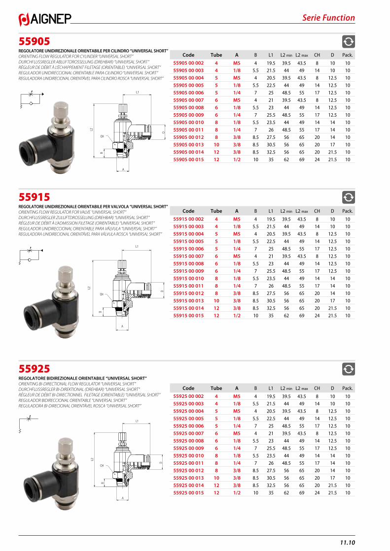
55900REGOLATORE UNIDIREZIONALE ORIENTABILE PER CILINDRO “UNIVERSAL SHORT” ORIENTING FLOW REGULATOR FOR CYLINDER “UNIVERSAL SHORT” DURCHFLUSSREGLER ABLUFTDROSSELUNG (DREHBAR) “UNIVERSAL SHORT” RÉGLEUR DE DÉBIT À L’ÉCHAPPEMENT FILETAGE (ORIENTABLE) “UNIVERSAL SHORT” REGULADOR UNIDIRECCIONAL ORIENTABLE PARA CILINDRO “UNIVERSAL SHORT” REGULADORA UNIDIRECIONAL ORIENTÁVEL PARA CILINDRO ROSCA “UNIVERSAL SHORT”
55910REGOLATORE UNIDIREZIONALE ORIENTABILE PER VALVOLA “UNIVERSAL SHORT” ORIENTING FLOW REGULATOR FOR VALVE “UNIVERSAL SHORT” DURCHFLUSSREGLER ZULUFTDROSSELUNG (DREHBAR) “UNIVERSAL SHORT” RÉGLEUR DE DÉBIT À L’ADMISSION FILETAGE (ORIENTABLE) “UNIVERSAL SHORT” REGULADOR UNIDIRECCIONAL ORIENTABLE PARA VÁLVULA “UNIVERSAL SHORT” REGULADORA UNIDIRECIONAL ORIENTÁVEL PARA VÁLVULA ROSCA “UNIVERSAL SHORT”
55920REGOLATORE BIDIREZIONALE ORIENTABILE “UNIVERSAL SHORT” ORIENTING BI-DIRECTIONAL FLOW REGULATOR “UNIVERSAL SHORT” DURCHFLUSSREGLER BI-DIREKTIONAL (DREHBAR) “UNIVERSAL SHORT” RÉGLEUR DE DÉBIT BI-DIRECTIONNEL FILETAGE (ORIENTABLE) “UNIVERSAL SHORT” REGULADOR BIDIRECCIONAL ORIENTABLE “UNIVERSAL SHORT” REGULADORA BI-DIRECIONAL ORIENTÁVEL ROSCA “UNIVERSAL SHORT”
Code Tube A B L1 L2 CH D Pack.
55900 00 002 4 M5 5.5 19.5 29.5 8 10 1055900 00 003 4 1/8 5.5 21.5 31 14 10 10
55900 00 004 5 M5 5.5 20.5 29.5 8 12.5 10
55900 00 005 5 1/8 5.5 22.5 31 14 12.5 10
55900 00 006 5 1/4 7 25 36.5 17 12.5 10
55900 00 007 6 M5 5.5 21 29.5 8 12.5 10
55900 00 008 6 1/8 5.5 23 31 14 12.5 10
55900 00 009 6 1/4 7 25.5 36.5 17 12.5 10
55900 00 010 8 1/8 5.5 23.5 31 14 14 10
55900 00 011 8 1/4 7 26 36.5 17 14 10
55900 00 012 8 3/8 8.5 27.5 42.5 20 14 10
55900 00 013 10 3/8 8.5 30.5 42.5 20 17 10
55900 00 014 12 3/8 8.5 32.5 42.5 20 21.5 10
55900 00 015 12 1/2 10 35 47 24 21.5 10
CHL2
B
A
L1
D
Code Tube A B L1 L2 CH D Pack.
55910 00 002 4 M5 4 19.5 29.5 8 10 1055910 00 003 4 1/8 5.5 21.5 31 14 10 10
55910 00 004 5 M5 4 20.5 29.5 8 12.5 10
55910 00 005 5 1/8 5.5 22.5 31 14 12.5 10
55910 00 006 5 1/4 7 25 36.5 17 12.5 10
55910 00 007 6 M5 4 21 29.5 8 12.5 10
55910 00 008 6 1/8 5.5 23 31 14 12.5 10
55910 00 009 6 1/4 7 25.5 36.5 17 12.5 10
55910 00 010 8 1/8 5.5 23.5 31 14 14 10
55910 00 011 8 1/4 7 26 36.5 17 14 10
55910 00 012 8 3/8 8.5 27.5 42.5 20 14 10
55910 00 013 10 3/8 8.5 30.5 42.5 20 17 10
55910 00 014 12 3/8 8.5 32.5 42.5 20 21.5 10
55910 00 015 12 1/2 10 35 47 24 21.5 10A
L2
B
CH
L1
D
Code Tube A B L1 L2 CH D Pack.
55920 00 002 4 M5 4 19.5 29.5 8 10 1055920 00 003 4 1/8 5.5 21.5 31 14 10 10
55920 00 004 5 M5 4 20.5 29.5 8 12.5 10
55920 00 005 5 1/8 5.5 22.5 31 14 12.5 10
55920 00 006 5 1/4 7 25 36.5 17 12.5 10
55920 00 007 6 M5 4 21 29.5 8 12.5 10
55920 00 008 6 1/8 5.5 23 31 14 12.5 10
55920 00 009 6 1/4 7 25.5 36.5 17 12.5 10
55920 00 010 8 1/8 5.5 23.5 31 14 14 10
55920 00 011 8 1/4 7 26 36.5 17 14 10
55920 00 012 8 3/8 8.5 27.5 42.5 20 14 10
55920 00 013 10 3/8 8.5 30.5 42.5 20 17 10
55920 00 014 12 3/8 8.5 32.5 42.5 20 21.5 10
55920 00 015 12 1/2 10 35 47 24 21.5 10A
L2
B
CH
L1
D
11.10
Serie Function
55905REGOLATORE UNIDIREZIONALE ORIENTABILE PER CILINDRO “UNIVERSAL SHORT” ORIENTING FLOW REGULATOR FOR CYLINDER “UNIVERSAL SHORT” DURCHFLUSSREGLER ABLUFTDROSSELUNG (DREHBAR) “UNIVERSAL SHORT” RÉGLEUR DE DÉBIT À L’ÉCHAPPEMENT FILETAGE (ORIENTABLE) “UNIVERSAL SHORT” REGULADOR UNIDIRECCIONAL ORIENTABLE PARA CILINDRO “UNIVERSAL SHORT” REGULADORA UNIDIRECIONAL ORIENTÁVEL PARA CILINDRO ROSCA “UNIVERSAL SHORT”
55915REGOLATORE UNIDIREZIONALE ORIENTABILE PER VALVOLA “UNIVERSAL SHORT” ORIENTING FLOW REGULATOR FOR VALVE “UNIVERSAL SHORT” DURCHFLUSSREGLER ZULUFTDROSSELUNG (DREHBAR) “UNIVERSAL SHORT” RÉGLEUR DE DÉBIT À L’ADMISSION FILETAGE (ORIENTABLE) “UNIVERSAL SHORT” REGULADOR UNIDIRECCIONAL ORIENTABLE PARA VÁLVULA “UNIVERSAL SHORT” REGULADORA UNIDIRECIONAL ORIENTÁVEL PARA VÁLVULA ROSCA “UNIVERSAL SHORT”
55925REGOLATORE BIDIREZIONALE ORIENTABILE “UNIVERSAL SHORT” ORIENTING BI-DIRECTIONAL FLOW REGULATOR “UNIVERSAL SHORT” DURCHFLUSSREGLER BI-DIREKTIONAL (DREHBAR) “UNIVERSAL SHORT” RÉGLEUR DE DÉBIT BI-DIRECTIONNEL FILETAGE (ORIENTABLE) “UNIVERSAL SHORT” REGULADOR BIDIRECCIONAL ORIENTABLE “UNIVERSAL SHORT” REGULADORA BI-DIRECIONAL ORIENTÁVEL ROSCA “UNIVERSAL SHORT”
Code Tube A B L1 L2 min L2 max CH D Pack.
55905 00 002 4 M5 4 19.5 39.5 43.5 8 10 1055905 00 003 4 1/8 5.5 21.5 44 49 14 10 10
55905 00 004 5 M5 4 20.5 39.5 43.5 8 12.5 10
55905 00 005 5 1/8 5.5 22.5 44 49 14 12.5 10
55905 00 006 5 1/4 7 25 48.5 55 17 12.5 10
55905 00 007 6 M5 4 21 39.5 43.5 8 12.5 10
55905 00 008 6 1/8 5.5 23 44 49 14 12.5 10
55905 00 009 6 1/4 7 25.5 48.5 55 17 12.5 10
55905 00 010 8 1/8 5.5 23.5 44 49 14 14 10
55905 00 011 8 1/4 7 26 48.5 55 17 14 10
55905 00 012 8 3/8 8.5 27.5 56 65 20 14 10
55905 00 013 10 3/8 8.5 30.5 56 65 20 17 10
55905 00 014 12 3/8 8.5 32.5 56 65 20 21.5 10
55905 00 015 12 1/2 10 35 62 69 24 21.5 10
A
L2
B
CH
L1
D
Code Tube A B L1 L2 min L2 max CH D Pack.
55915 00 002 4 M5 4 19.5 39.5 43.5 8 10 1055915 00 003 4 1/8 5.5 21.5 44 49 14 10 10
55915 00 004 5 M5 4 20.5 39.5 43.5 8 12.5 10
55915 00 005 5 1/8 5.5 22.5 44 49 14 12.5 10
55915 00 006 5 1/4 7 25 48.5 55 17 12.5 10
55915 00 007 6 M5 4 21 39.5 43.5 8 12.5 10
55915 00 008 6 1/8 5.5 23 44 49 14 12.5 10
55915 00 009 6 1/4 7 25.5 48.5 55 17 12.5 10
55915 00 010 8 1/8 5.5 23.5 44 49 14 14 10
55915 00 011 8 1/4 7 26 48.5 55 17 14 10
55915 00 012 8 3/8 8.5 27.5 56 65 20 14 10
55915 00 013 10 3/8 8.5 30.5 56 65 20 17 10
55915 00 014 12 3/8 8.5 32.5 56 65 20 21.5 10
55915 00 015 12 1/2 10 35 62 69 24 21.5 10
A
L2
B
CH
L1
D
Code Tube A B L1 L2 min L2 max CH D Pack.
55925 00 002 4 M5 4 19.5 39.5 43.5 8 10 1055925 00 003 4 1/8 5.5 21.5 44 49 14 10 10
55925 00 004 5 M5 4 20.5 39.5 43.5 8 12.5 10
55925 00 005 5 1/8 5.5 22.5 44 49 14 12.5 10
55925 00 006 5 1/4 7 25 48.5 55 17 12.5 10
55925 00 007 6 M5 4 21 39.5 43.5 8 12.5 10
55925 00 008 6 1/8 5.5 23 44 49 14 12.5 10
55925 00 009 6 1/4 7 25.5 48.5 55 17 12.5 10
55925 00 010 8 1/8 5.5 23.5 44 49 14 14 10
55925 00 011 8 1/4 7 26 48.5 55 17 14 10
55925 00 012 8 3/8 8.5 27.5 56 65 20 14 10
55925 00 013 10 3/8 8.5 30.5 56 65 20 17 10
55925 00 014 12 3/8 8.5 32.5 56 65 20 21.5 10
55925 00 015 12 1/2 10 35 62 69 24 21.5 10A
L2
B
CH
L1
D
Serie Function
11.11
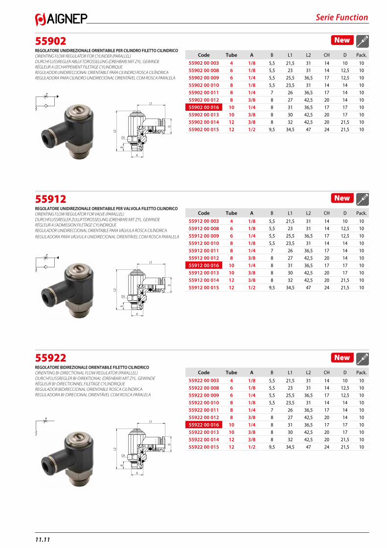
55902REGOLATORE UNIDIREZIONALE ORIENTABILE PER CILINDRO FILETTO CILINDRICO ORIENTING FLOW REGULATOR FOR CYLINDER (PARALLEL) DURCHFLUSSREGLER ABLUFTDROSSELUNG (DREHBAR) MIT ZYL. GEWINDE RÉGLEUR A L’ECHAPPEMENT FILETAGE CYLINDRIQUE REGULADOR UNIDIRECCIONAL ORIENTABLE PARA CILINDRO ROSCA CILÍNDRICA REGULADORA PARA CILINDRO UNIDIRECIONAL ORIENTÁVEL COM ROSCA PARALELA
55912REGOLATORE UNIDIREZIONALE ORIENTABILE PER VALVOLA FILETTO CILINDRICO ORIENTING FLOW REGULATOR FOR VALVE (PARALLEL) DURCHFLUSSREGLER ZULUFTDROSSELUNG (DREHBAR) MIT ZYL. GEWINDE RÉGLEUR A L’ADMISSION FILETAGE CYLINDRIQUE REGULADOR UNIDIRECCIONAL ORIENTABLE PARA VÁLVULA ROSCA CILÍNDRICA REGULADORA PARA VÁLVULA UNIDIRECIONAL ORIENTÁVEL COM ROSCA PARALELA
55922REGOLATORE BIDIREZIONALE ORIENTABILE FILETTO CILINDRICO ORIENTING BI-DIRECTIONAL FLOW REGULATOR (PARALLEL) DURCHFLUSSREGLER BI-DIREKTIONAL (DREHBAR) MIT ZYL. GEWINDE RÉGLEUR BI-DIRECTIONNEL FILETAGE CYLINDRIQUE REGULADOR BIDIRECCIONAL ORIENTABLE ROSCA CILÍNDRICA REGULADORA BI-DIRECIONAL ORIENTÁVEL COM ROSCA PARALELA
New
Code Tube A B L1 L2 CH D Pack.
55902 00 003 4 1/8 5,5 21,5 31 14 10 1055902 00 008 6 1/8 5,5 23 31 14 12,5 10
55902 00 009 6 1/4 5,5 25,5 36,5 17 12,5 10
55902 00 010 8 1/8 5,5 23,5 31 14 14 10
55902 00 011 8 1/4 7 26 36,5 17 14 10
55902 00 012 8 3/8 8 27 42,5 20 14 10
55902 00 016 10 1/4 8 31 36,5 17 17 10
55902 00 013 10 3/8 8 30 42,5 20 17 10
55902 00 014 12 3/8 8 32 42,5 20 21,5 10
55902 00 015 12 1/2 9,5 34,5 47 24 21,5 10
A
L2
B
L1
D
CH
New
Code Tube A B L1 L2 CH D Pack.
55912 00 003 4 1/8 5,5 21,5 31 14 10 1055912 00 008 6 1/8 5,5 23 31 14 12,5 10
55912 00 009 6 1/4 5,5 25,5 36,5 17 12,5 10
55912 00 010 8 1/8 5,5 23,5 31 14 14 10
55912 00 011 8 1/4 7 26 36,5 17 14 10
55912 00 012 8 3/8 8 27 42,5 20 14 10
55912 00 016 10 1/4 8 31 36,5 17 17 10
55912 00 013 10 3/8 8 30 42,5 20 17 10
55912 00 014 12 3/8 8 32 42,5 20 21,5 10
55912 00 015 12 1/2 9,5 34,5 47 24 21,5 10
A
L2
B
L1
D
CH
New
Code Tube A B L1 L2 CH D Pack.
55922 00 003 4 1/8 5,5 21,5 31 14 10 1055922 00 008 6 1/8 5,5 23 31 14 12,5 10
55922 00 009 6 1/4 5,5 25,5 36,5 17 12,5 10
55922 00 010 8 1/8 5,5 23,5 31 14 14 10
55922 00 011 8 1/4 7 26 36,5 17 14 10
55922 00 012 8 3/8 8 27 42,5 20 14 10
55922 00 016 10 1/4 8 31 36,5 17 17 10
55922 00 013 10 3/8 8 30 42,5 20 17 10
55922 00 014 12 3/8 8 32 42,5 20 21,5 10
55922 00 015 12 1/2 9,5 34,5 47 24 21,5 10
A
L2
B
L1
D
CH
11.12
Serie Function
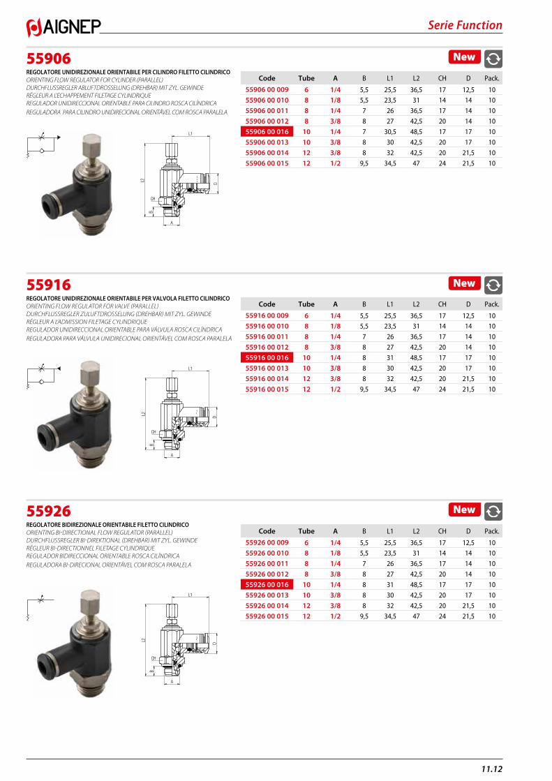
55906REGOLATORE UNIDIREZIONALE ORIENTABILE PER CILINDRO FILETTO CILINDRICO ORIENTING FLOW REGULATOR FOR CYLINDER (PARALLEL) DURCHFLUSSREGLER ABLUFTDROSSELUNG (DREHBAR) MIT ZYL. GEWINDE RÉGLEUR A L’ECHAPPEMENT FILETAGE CYLINDRIQUE REGULADOR UNIDIRECCIONAL ORIENTABLE PARA CILINDRO ROSCA CILÍNDRICA REGULADORA PARA CILINDRO UNIDIRECIONAL ORIENTÁVEL COM ROSCA PARALELA
55916REGOLATORE UNIDIREZIONALE ORIENTABILE PER VALVOLA FILETTO CILINDRICO ORIENTING FLOW REGULATOR FOR VALVE (PARALLEL) DURCHFLUSSREGLER ZULUFTDROSSELUNG (DREHBAR) MIT ZYL. GEWINDE RÉGLEUR A L’ADMISSION FILETAGE CYLINDRIQUE REGULADOR UNIDIRECCIONAL ORIENTABLE PARA VÁLVULA ROSCA CILÍNDRICA REGULADORA PARA VÁLVULA UNIDIRECIONAL ORIENTÁVEL COM ROSCA PARALELA
55926REGOLATORE BIDIREZIONALE ORIENTABILE FILETTO CILINDRICO ORIENTING BI-DIRECTIONAL FLOW REGULATOR (PARALLEL) DURCHFLUSSREGLER BI-DIREKTIONAL (DREHBAR) MIT ZYL. GEWINDE RÉGLEUR BI-DIRECTIONNEL FILETAGE CYLINDRIQUE REGULADOR BIDIRECCIONAL ORIENTABLE ROSCA CILÍNDRICA REGULADORA BI-DIRECIONAL ORIENTÁVEL COM ROSCA PARALELA
New
Code Tube A B L1 L2 CH D Pack.
55906 00 009 6 1/4 5,5 25,5 36,5 17 12,5 1055906 00 010 8 1/8 5,5 23,5 31 14 14 10
55906 00 011 8 1/4 7 26 36,5 17 14 10
55906 00 012 8 3/8 8 27 42,5 20 14 10
55906 00 016 10 1/4 7 30,5 48,5 17 17 10
55906 00 013 10 3/8 8 30 42,5 20 17 10
55906 00 014 12 3/8 8 32 42,5 20 21,5 10
55906 00 015 12 1/2 9,5 34,5 47 24 21,5 10
A
B
L1
DL2
CH
New
Code Tube A B L1 L2 CH D Pack.
55916 00 009 6 1/4 5,5 25,5 36,5 17 12,5 1055916 00 010 8 1/8 5,5 23,5 31 14 14 10
55916 00 011 8 1/4 7 26 36,5 17 14 10
55916 00 012 8 3/8 8 27 42,5 20 14 10
55916 00 016 10 1/4 8 31 48,5 17 17 10
55916 00 013 10 3/8 8 30 42,5 20 17 10
55916 00 014 12 3/8 8 32 42,5 20 21,5 10
55916 00 015 12 1/2 9,5 34,5 47 24 21,5 10
A
B
L1
DL2
CH
New
Code Tube A B L1 L2 CH D Pack.
55926 00 009 6 1/4 5,5 25,5 36,5 17 12,5 1055926 00 010 8 1/8 5,5 23,5 31 14 14 10
55926 00 011 8 1/4 7 26 36,5 17 14 10
55926 00 012 8 3/8 8 27 42,5 20 14 10
55926 00 016 10 1/4 8 31 48,5 17 17 10
55926 00 013 10 3/8 8 30 42,5 20 17 10
55926 00 014 12 3/8 8 32 42,5 20 21,5 10
55926 00 015 12 1/2 9,5 34,5 47 24 21,5 10
A
B
L1
DL2
CH
Serie Function
11.13
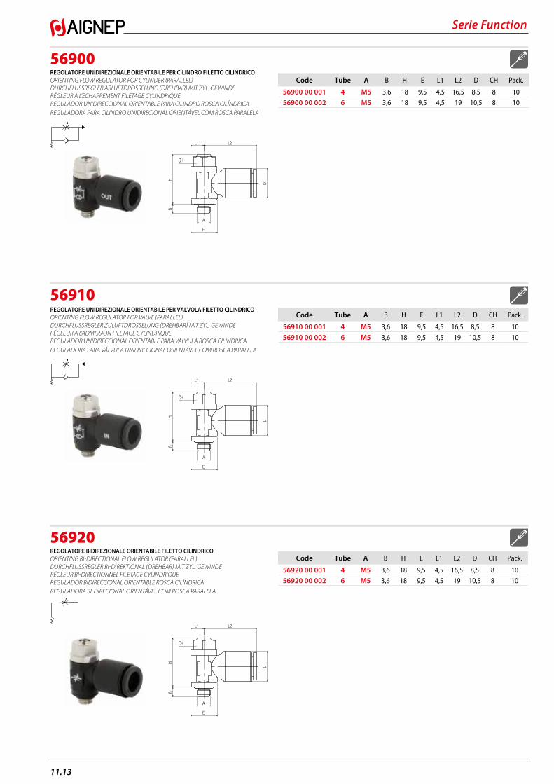
56900REGOLATORE UNIDIREZIONALE ORIENTABILE PER CILINDRO FILETTO CILINDRICO ORIENTING FLOW REGULATOR FOR CYLINDER (PARALLEL) DURCHFLUSSREGLER ABLUFTDROSSELUNG (DREHBAR) MIT ZYL. GEWINDE RÉGLEUR A L’ECHAPPEMENT FILETAGE CYLINDRIQUE REGULADOR UNIDIRECCIONAL ORIENTABLE PARA CILINDRO ROSCA CILÍNDRICA REGULADORA PARA CILINDRO UNIDIRECIONAL ORIENTÁVEL COM ROSCA PARALELA
56910REGOLATORE UNIDIREZIONALE ORIENTABILE PER VALVOLA FILETTO CILINDRICO ORIENTING FLOW REGULATOR FOR VALVE (PARALLEL) DURCHFLUSSREGLER ZULUFTDROSSELUNG (DREHBAR) MIT ZYL. GEWINDE RÉGLEUR A L’ADMISSION FILETAGE CYLINDRIQUE REGULADOR UNIDIRECCIONAL ORIENTABLE PARA VÁLVULA ROSCA CILÍNDRICA REGULADORA PARA VÁLVULA UNIDIRECIONAL ORIENTÁVEL COM ROSCA PARALELA
56920REGOLATORE BIDIREZIONALE ORIENTABILE FILETTO CILINDRICO ORIENTING BI-DIRECTIONAL FLOW REGULATOR (PARALLEL) DURCHFLUSSREGLER BI-DIREKTIONAL (DREHBAR) MIT ZYL. GEWINDE RÉGLEUR BI-DIRECTIONNEL FILETAGE CYLINDRIQUE REGULADOR BIDIRECCIONAL ORIENTABLE ROSCA CILÍNDRICA REGULADORA BI-DIRECIONAL ORIENTÁVEL COM ROSCA PARALELA
Code Tube A B H E L1 L2 D CH Pack.
56900 00 001 4 M5 3,6 18 9,5 4,5 16,5 8,5 8 10
56900 00 002 6 M5 3,6 18 9,5 4,5 19 10,5 8 10
E
BH
L1 L2
D
A
CH
Code Tube A B H E L1 L2 D CH Pack.
56910 00 001 4 M5 3,6 18 9,5 4,5 16,5 8,5 8 10
56910 00 002 6 M5 3,6 18 9,5 4,5 19 10,5 8 10
E
BH
L1 L2
D
A
CH
Code Tube A B H E L1 L2 D CH Pack.
56920 00 001 4 M5 3,6 18 9,5 4,5 16,5 8,5 8 10
56920 00 002 6 M5 3,6 18 9,5 4,5 19 10,5 8 10
E
BH
L1 L2
D
A
CH
11.14
Serie Function
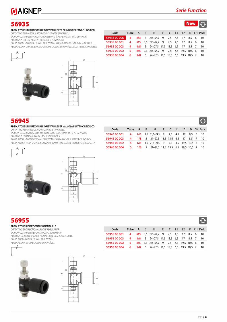
56935REGOLATORE UNIDIREZIONALE ORIENTABILE PER CILINDRO FILETTO CILINDRICO ORIENTING FLOW REGULATOR FOR CYLINDER (PARALLEL) DURCHFLUSSREGLER ABLUFTDROSSELUNG (DREHBAR) MIT ZYL. GEWINDE RÉGLEUR A L’ECHAPPEMENT FILETAGE CYLINDRIQUE REGULADOR UNIDIRECCIONAL ORIENTABLE PARA CILINDRO ROSCA CILÍNDRICA REGULADORA PARA CILINDRO UNIDIRECIONAL ORIENTÁVEL COM ROSCA PARALELA
56945REGOLATORE UNIDIREZIONALE ORIENTABILE PER VALVOLA FILETTO CILINDRICO ORIENTING FLOW REGULATOR FOR VALVE (PARALLEL) DURCHFLUSSREGLER ZULUFTDROSSELUNG (DREHBAR) MIT ZYL. GEWINDE RÉGLEUR A L’ADMISSION FILETAGE CYLINDRIQUE REGULADOR UNIDIRECCIONAL ORIENTABLE PARA VÁLVULA ROSCA CILÍNDRICA REGULADORA PARA VÁLVULA UNIDIRECIONAL ORIENTÁVEL COM ROSCA PARALELA
56955REGOLATORE BIDIREZIONALE ORIENTABILE ORIENTING BI-DIRECTIONAL FLOW REGULATOR DURCHFLUSSREGLER BI-DIREKTIONAL (DREHBAR) RÉGLEUR DE DÉBIT BI-DIRECTIONNEL FILETAGE (ORIENTABLE) REGULADOR BIDIRECCIONAL ORIENTABLE REGULADORA BI-DIRECIONAL ORIENTÁVEL
New
Code Tube A B H E C L1 L2 D CH Pack.
56935 00 006 4 M3 3 21,5÷24,5 9 7,5 4,5 17 8,5 6 10
56935 00 001 4 M5 3,6 21,5÷24,5 9 7,5 4,5 17 8,5 6 10
56935 00 003 4 1/8 5 24÷27,5 11,5 13,5 6,5 17 8,5 7 10
56935 00 002 6 M5 3,6 21,5÷24,5 9 7,5 4,5 19,5 10,5 6 10
56935 00 004 6 1/8 5 24÷27,5 11,5 13,5 6,5 19,5 10,5 7 10
D
HB
A
E
C
L1 L2
CH
Code Tube A B H E C L1 L2 D CH Pack.
56945 00 001 4 M5 3,6 21,5÷24,5 9 7,5 4,5 17 8,5 6 10
56945 00 003 4 1/8 5 24÷27,5 11,5 13,5 6,5 17 8,5 7 10
56945 00 002 6 M5 3,6 21,5÷24,5 9 7,5 4,5 19,5 10,5 6 10
56945 00 004 6 1/8 5 24÷27,5 11,5 13,5 6,5 19,5 10,5 7 10
D
HB
A
E
C
L1 L2
CH
Code Tube A B H E C L1 L2 D CH Pack.
56955 00 001 4 M5 3,6 21,5÷24,5 9 7,5 4,5 17 8,5 6 10
56955 00 003 4 1/8 5 24÷27,5 11,5 13,5 6,5 17 8,5 7 10
56955 00 002 6 M5 3,6 21,5÷24,5 9 7,5 4,5 19,5 10,5 6 10
56955 00 004 6 1/8 5 24÷27,5 11,5 13,5 6,5 19,5 10,5 7 10
D
HB
A
E
C
L1 L2
CH
Serie Function
11.15
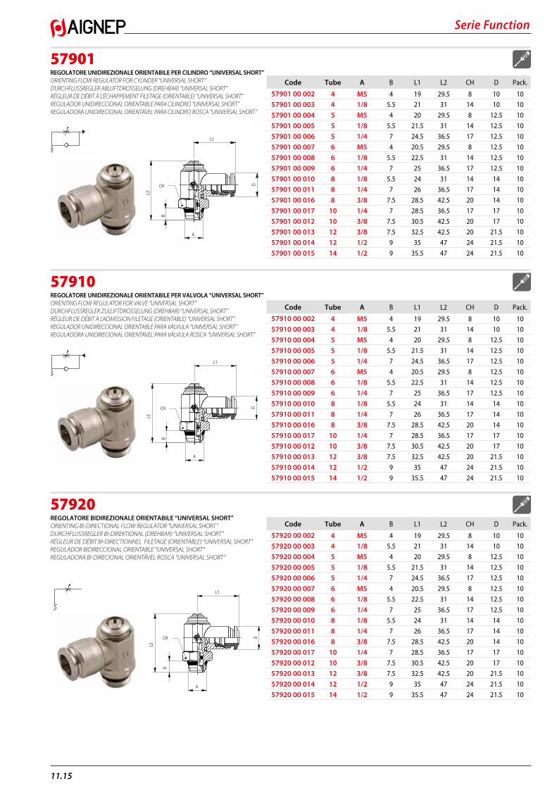
57901REGOLATORE UNIDIREZIONALE ORIENTABILE PER CILINDRO “UNIVERSAL SHORT” ORIENTING FLOW REGULATOR FOR CYLINDER “UNIVERSAL SHORT” DURCHFLUSSREGLER ABLUFTDROSSELUNG (DREHBAR) “UNIVERSAL SHORT” RÉGLEUR DE DÉBIT À L’ÉCHAPPEMENT FILETAGE (ORIENTABLE) “UNIVERSAL SHORT” REGULADOR UNIDIRECCIONAL ORIENTABLE PARA CILINDRO “UNIVERSAL SHORT” REGULADORA UNIDIRECIONAL ORIENTÁVEL PARA CILINDRO ROSCA “UNIVERSAL SHORT”
57910REGOLATORE UNIDIREZIONALE ORIENTABILE PER VALVOLA “UNIVERSAL SHORT” ORIENTING FLOW REGULATOR FOR VALVE “UNIVERSAL SHORT” DURCHFLUSSREGLER ZULUFTDROSSELUNG (DREHBAR) “UNIVERSAL SHORT” RÉGLEUR DE DÉBIT À L’ADMISSION FILETAGE (ORIENTABLE) “UNIVERSAL SHORT” REGULADOR UNIDIRECCIONAL ORIENTABLE PARA VÁLVULA “UNIVERSAL SHORT” REGULADORA UNIDIRECIONAL ORIENTÁVEL PARA VÁLVULA ROSCA “UNIVERSAL SHORT”
57920REGOLATORE BIDIREZIONALE ORIENTABILE “UNIVERSAL SHORT” ORIENTING BI-DIRECTIONAL FLOW REGULATOR “UNIVERSAL SHORT” DURCHFLUSSREGLER BI-DIREKTIONAL (DREHBAR) “UNIVERSAL SHORT” RÉGLEUR DE DÉBIT BI-DIRECTIONNEL FILETAGE (ORIENTABLE) “UNIVERSAL SHORT” REGULADOR BIDIRECCIONAL ORIENTABLE “UNIVERSAL SHORT” REGULADORA BI-DIRECIONAL ORIENTÁVEL ROSCA “UNIVERSAL SHORT”
Code Tube A B L1 L2 CH D Pack.
57901 00 002 4 M5 4 19 29.5 8 10 1057901 00 003 4 1/8 5.5 21 31 14 10 10
57901 00 004 5 M5 4 20 29.5 8 12.5 10
57901 00 005 5 1/8 5.5 21.5 31 14 12.5 10
57901 00 006 5 1/4 7 24.5 36.5 17 12.5 10
57901 00 007 6 M5 4 20.5 29.5 8 12.5 10
57901 00 008 6 1/8 5.5 22.5 31 14 12.5 10
57901 00 009 6 1/4 7 25 36.5 17 12.5 10
57901 00 010 8 1/8 5.5 24 31 14 14 10
57901 00 011 8 1/4 7 26 36.5 17 14 10
57901 00 016 8 3/8 7.5 28.5 42.5 20 14 10
57901 00 017 10 1/4 7 28.5 36.5 17 17 10
57901 00 012 10 3/8 7.5 30.5 42.5 20 17 10
57901 00 013 12 3/8 7.5 32.5 42.5 20 21.5 10
57901 00 014 12 1/2 9 35 47 24 21.5 10
57901 00 015 14 1/2 9 35.5 47 24 21.5 10
L1
L2
CH
B
A
D
Code Tube A B L1 L2 CH D Pack.
57910 00 002 4 M5 4 19 29.5 8 10 1057910 00 003 4 1/8 5.5 21 31 14 10 10
57910 00 004 5 M5 4 20 29.5 8 12.5 10
57910 00 005 5 1/8 5.5 21.5 31 14 12.5 10
57910 00 006 5 1/4 7 24.5 36.5 17 12.5 10
57910 00 007 6 M5 4 20.5 29.5 8 12.5 10
57910 00 008 6 1/8 5.5 22.5 31 14 12.5 10
57910 00 009 6 1/4 7 25 36.5 17 12.5 10
57910 00 010 8 1/8 5.5 24 31 14 14 10
57910 00 011 8 1/4 7 26 36.5 17 14 10
57910 00 016 8 3/8 7.5 28.5 42.5 20 14 10
57910 00 017 10 1/4 7 28.5 36.5 17 17 10
57910 00 012 10 3/8 7.5 30.5 42.5 20 17 10
57910 00 013 12 3/8 7.5 32.5 42.5 20 21.5 10
57910 00 014 12 1/2 9 35 47 24 21.5 10
57910 00 015 14 1/2 9 35.5 47 24 21.5 10
L1
L2
CH
B
A
D
Code Tube A B L1 L2 CH D Pack.
57920 00 002 4 M5 4 19 29.5 8 10 1057920 00 003 4 1/8 5.5 21 31 14 10 10
57920 00 004 5 M5 4 20 29.5 8 12.5 10
57920 00 005 5 1/8 5.5 21.5 31 14 12.5 10
57920 00 006 5 1/4 7 24.5 36.5 17 12.5 10
57920 00 007 6 M5 4 20.5 29.5 8 12.5 10
57920 00 008 6 1/8 5.5 22.5 31 14 12.5 10
57920 00 009 6 1/4 7 25 36.5 17 12.5 10
57920 00 010 8 1/8 5.5 24 31 14 14 10
57920 00 011 8 1/4 7 26 36.5 17 14 10
57920 00 016 8 3/8 7.5 28.5 42.5 20 14 10
57920 00 017 10 1/4 7 28.5 36.5 17 17 10
57920 00 012 10 3/8 7.5 30.5 42.5 20 17 10
57920 00 013 12 3/8 7.5 32.5 42.5 20 21.5 10
57920 00 014 12 1/2 9 35 47 24 21.5 10
57920 00 015 14 1/2 9 35.5 47 24 21.5 10
L1
L2
CH
B
A
D
11.16
Serie Function
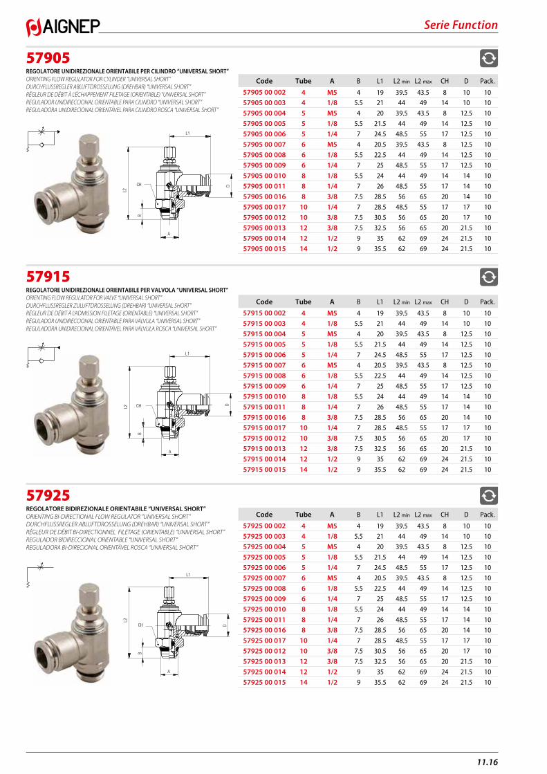
57905REGOLATORE UNIDIREZIONALE ORIENTABILE PER CILINDRO “UNIVERSAL SHORT” ORIENTING FLOW REGULATOR FOR CYLINDER “UNIVERSAL SHORT” DURCHFLUSSREGLER ABLUFTDROSSELUNG (DREHBAR) “UNIVERSAL SHORT” RÉGLEUR DE DÉBIT À L’ÉCHAPPEMENT FILETAGE (ORIENTABLE) “UNIVERSAL SHORT” REGULADOR UNIDIRECCIONAL ORIENTABLE PARA CILINDRO “UNIVERSAL SHORT” REGULADORA UNIDIRECIONAL ORIENTÁVEL PARA CILINDRO ROSCA “UNIVERSAL SHORT”
57915REGOLATORE UNIDIREZIONALE ORIENTABILE PER VALVOLA “UNIVERSAL SHORT” ORIENTING FLOW REGULATOR FOR VALVE “UNIVERSAL SHORT” DURCHFLUSSREGLER ZULUFTDROSSELUNG (DREHBAR) “UNIVERSAL SHORT” RÉGLEUR DE DÉBIT À L’ADMISSION FILETAGE (ORIENTABLE) “UNIVERSAL SHORT” REGULADOR UNIDIRECCIONAL ORIENTABLE PARA VÁLVULA “UNIVERSAL SHORT” REGULADORA UNIDIRECIONAL ORIENTÁVEL PARA VÁLVULA ROSCA “UNIVERSAL SHORT”
57925REGOLATORE BIDIREZIONALE ORIENTABILE “UNIVERSAL SHORT” ORIENTING BI-DIRECTIONAL FLOW REGULATOR “UNIVERSAL SHORT” DURCHFLUSSREGLER ABLUFTDROSSELUNG (DREHBAR) “UNIVERSAL SHORT” RÉGLEUR DE DÉBIT BI-DIRECTIONNEL FILETAGE (ORIENTABLE) “UNIVERSAL SHORT” REGULADOR BIDIRECCIONAL ORIENTABLE “UNIVERSAL SHORT” REGULADORA BI-DIRECIONAL ORIENTÁVEL ROSCA “UNIVERSAL SHORT”
Code Tube A B L1 L2 min L2 max CH D Pack.
57905 00 002 4 M5 4 19 39.5 43.5 8 10 1057905 00 003 4 1/8 5.5 21 44 49 14 10 10
57905 00 004 5 M5 4 20 39.5 43.5 8 12.5 10
57905 00 005 5 1/8 5.5 21.5 44 49 14 12.5 10
57905 00 006 5 1/4 7 24.5 48.5 55 17 12.5 10
57905 00 007 6 M5 4 20.5 39.5 43.5 8 12.5 10
57905 00 008 6 1/8 5.5 22.5 44 49 14 12.5 10
57905 00 009 6 1/4 7 25 48.5 55 17 12.5 10
57905 00 010 8 1/8 5.5 24 44 49 14 14 10
57905 00 011 8 1/4 7 26 48.5 55 17 14 10
57905 00 016 8 3/8 7.5 28.5 56 65 20 14 10
57905 00 017 10 1/4 7 28.5 48.5 55 17 17 10
57905 00 012 10 3/8 7.5 30.5 56 65 20 17 10
57905 00 013 12 3/8 7.5 32.5 56 65 20 21.5 10
57905 00 014 12 1/2 9 35 62 69 24 21.5 10
57905 00 015 14 1/2 9 35.5 62 69 24 21.5 10
L1
L2
CH
B
A
D
Code Tube A B L1 L2 min L2 max CH D Pack.
57915 00 002 4 M5 4 19 39.5 43.5 8 10 1057915 00 003 4 1/8 5.5 21 44 49 14 10 10
57915 00 004 5 M5 4 20 39.5 43.5 8 12.5 10
57915 00 005 5 1/8 5.5 21.5 44 49 14 12.5 10
57915 00 006 5 1/4 7 24.5 48.5 55 17 12.5 10
57915 00 007 6 M5 4 20.5 39.5 43.5 8 12.5 10
57915 00 008 6 1/8 5.5 22.5 44 49 14 12.5 10
57915 00 009 6 1/4 7 25 48.5 55 17 12.5 10
57915 00 010 8 1/8 5.5 24 44 49 14 14 10
57915 00 011 8 1/4 7 26 48.5 55 17 14 10
57915 00 016 8 3/8 7.5 28.5 56 65 20 14 10
57915 00 017 10 1/4 7 28.5 48.5 55 17 17 10
57915 00 012 10 3/8 7.5 30.5 56 65 20 17 10
57915 00 013 12 3/8 7.5 32.5 56 65 20 21.5 10
57915 00 014 12 1/2 9 35 62 69 24 21.5 10
57915 00 015 14 1/2 9 35.5 62 69 24 21.5 10
L1
L2 CH
B
A
D
Code Tube A B L1 L2 min L2 max CH D Pack.
57925 00 002 4 M5 4 19 39.5 43.5 8 10 1057925 00 003 4 1/8 5.5 21 44 49 14 10 10
57925 00 004 5 M5 4 20 39.5 43.5 8 12.5 10
57925 00 005 5 1/8 5.5 21.5 44 49 14 12.5 10
57925 00 006 5 1/4 7 24.5 48.5 55 17 12.5 10
57925 00 007 6 M5 4 20.5 39.5 43.5 8 12.5 10
57925 00 008 6 1/8 5.5 22.5 44 49 14 12.5 10
57925 00 009 6 1/4 7 25 48.5 55 17 12.5 10
57925 00 010 8 1/8 5.5 24 44 49 14 14 10
57925 00 011 8 1/4 7 26 48.5 55 17 14 10
57925 00 016 8 3/8 7.5 28.5 56 65 20 14 10
57925 00 017 10 1/4 7 28.5 48.5 55 17 17 10
57925 00 012 10 3/8 7.5 30.5 56 65 20 17 10
57925 00 013 12 3/8 7.5 32.5 56 65 20 21.5 10
57925 00 014 12 1/2 9 35 62 69 24 21.5 10
57925 00 015 14 1/2 9 35.5 62 69 24 21.5 10
L1
L2
CH
B
A
D
11.17
Serie Function
REGOLATORI DI PORTATA SERIE 8900FLOW REGULATORS VALVES 8900 SERIES
DURCHFLUSSREGLER SERIE 8900RÉGLEURS DE DÉBIT SÉRIE 8900
REGULADORES DE CAUDAL SERIE 8900REGULADORAS DE VAZÃO SÉRIE 8900
CARATTERISTICHE TECNICHE TECHNICAL CHARACTERISTICS TECHNISCHE ANGABEN CARACTÉRISTIQUES TECHNIQUES CARACTERÍSTICAS TÉCNICAS CARACTERÍSTICAS TÉCNICAS
1 bar (0.1 MPa)
10 bar (1 MPa)
Fluidi compatibili Aria compressa
Fluids Compressed air
Geeignete Medien Druckluft
Fluides compatibles Air comprimé
Fluidos compatibles Aire comprimido
Fluidos compatíveis Ar comprimido
Pressioni
Pressures
Druckbereich
Pressions
Presiones
Pressões
Bar
- 20 °C+ 80 °C
Temperature
Temperatures
Temperatur
Températures
Temperaturas
Temperaturas
PTESFR
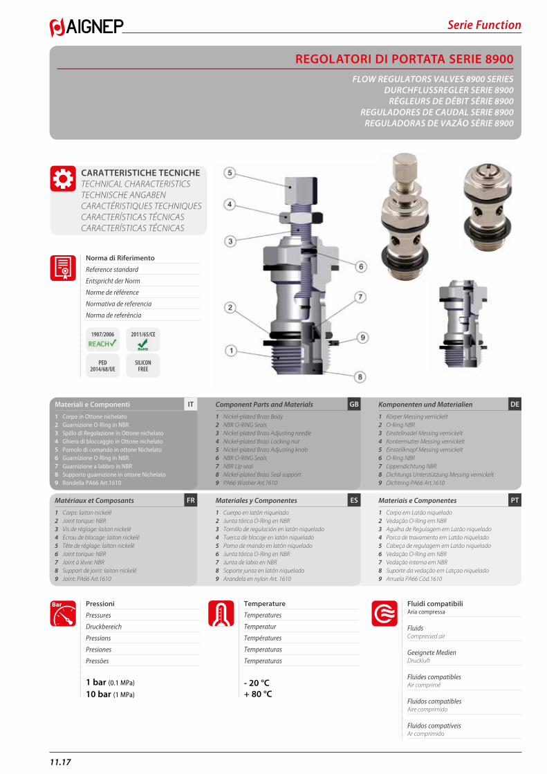
DEGBITMateriali e Componenti
1 Corpo in Ottone nichelato2 Guarnizione O-Ring in NBR3 Spillo di Regolazione in Ottone nichelato4 Ghiera di bloccaggio in Ottone nichelato5 Pomolo di comando in ottone Nichelato6 Guarnizione O-Ring in NBR7 Guarnizione a labbro in NBR8 Supporto guarnizione in ottone Nichelato9 Rondella PA66 Art.1610
Matériaux et Composants
1 Corps: laiton nickelé2 Joint torique: NBR 3 Vis de réglage: laiton nickelé 4 Ecrou de blocage: laiton nickelé 5 Tête de réglage: laiton nickelé6 Joint torique: NBR7 Joint à lèvre: NBR8 Support de joint: laiton nickelé9 Joint: PA66 Art.1610
Component Parts and Materials
1 Nickel-plated Brass Body2 NBR O-RING Seals3 Nickel-plated Brass Adjusting needle4 Nickel-plated Brass Locking nut5 Nickel-plated Brass Adjusting knob6 NBR O-RING Seals7 NBR Lip seal8 Nickel-plated Brass Seal support9 PA66 Washer Art.1610
Materiales y Componentes
1 Cuerpo en latón niquelado2 Junta tórica O-Ring en NBR3 Tornillo de regulación en latón niquelado4 Tuerca de blocaje en latón niquelado5 Pomo de mando en latón niquelado6 Junta tórica O-Ring en NBR7 Junta de labio en NBR8 Soporte junta en latón niquelado9 Arandela en nylon Art. 1610
Komponenten und Materialien
1 Körper Messing vernickelt2 O-Ring NBR 3 Einstellnadel Messing vernickelt4 Kontermutter Messing vernickelt5 Einstellknopf Messing vernickelt6 O-Ring NBR7 Lippendichtung NBR8 Dichtungs Unterstützung Messing vernickelt9 Dichtring PA66 Art.1610
Materiais e Componentes
1 Corpo em Latão niquelado 2 Vedação O-Ring em NBR3 Agulha de Regulagem em Latão niquelado 4 Porca de travamento em Latão niquelado 5 Cabeça de regulagem em Latão niquelado 6 Vedação O-Ring em NBR7 Vedação interna em NBR8 Suporte da vedação em Latçao niquelado 9 Arruela PA66 Cód.1610
Norma di Riferimento
Reference standard
Entspricht der Norm
Norme de référence
Normativa de referencia
Norma de referência
1907/2006 2011/65/CE
PED 2014/68/UE
SILICON FREE
11.18
Serie Function
UNIDIREZIONALE PER CILINDRO
UNI-DIRECTIONAL FOR CYLINDER
DROSSELUNG FÜR ZYLINDER (ABLUFT)
UNIDIRECTIONNEL À L’ÉCHAPPEMENT
UNIDIRECCIONAL PARA CILINDRO
UNIDIRECIONAL PARA CILINDRO
UNIDIREZIONALE PER VAVOLA
UNI-DIRECTIONAL FOR VALVE
DROSSELUNG FÜR ZYLINDER (ZULUFT)
UNIDIRECTIONNEL À L’ADMISSION
UNIDIRECCIONAL PARA VÁLVULA
UNIDIRECIONAL PARA VÁLVULA
BIDIREZIONALE
BI-DIRECTIONAL
BI-DIREKTIONAL (OHNE RÜCKSCHLAG)
BI-DIRECTIONNEL
BIDIRECCIONAL
BI-DIRECIONAL
C V B
C V B
C V B
C V B
C V B
C V B
DEGBITFilettatura
Gas cilindrica conforme ISO 228 Classe A.
Threads
Parallel gas in conformity with ISO 228 Class A.
Gewindearten
Zylindrisches Gewinde nach Norm ISO 228 Classe A.
PTESFRFiletages
Filetage cylindrique conforme ISO 228 Class A.
Roscas
Gas cilíndrica conforme ISO 228 Clase A.
Roscas
Gas paralela conforme ISO 228 Classe A.
CODE:
8900 - 8905
CODE:
8910 - 8915
CODE: 8920 - 8925
Serie Function
11.19
8900REGOLATORE DI FLUSSO UNIDIREZIONALE PER CILINDRO FLOW REGULATOR FOR CYLINDER DURCHFLUSSREGLER ABLUFTDROSSELUNG VIS RÉGLEUR DE DÉBIT À L’ÉCHAPPEMENT TORNILLO REGULADOR UNIDIRECCIONAL PARA CILINDRO REGULADORA DE VAZÃO UNIDIRECIONAL PARA CILINDRO
8910REGOLATORE DI FLUSSO UNIDIREZIONALE PER VALVOLA FLOW REGULATOR FOR VALVE DURCHFLUSSREGLER ZULUFTDROSSELUNG VIS RÉGLEUR DE DÉBIT À L’ADMISSION TORNILLO REGULADOR UNIDIRECCIONAL PARA VÁLVULA REGULADORA DE VAZÃO UNIDIRECIONAL PARA VÁLVULA
8920REGOLATORE Dl FLUSSO BIDIREZIONALE BI-DIRECTIONAL FLOW REGULATOR DURCHFLUSSREGLER BI-DIREKTIONAL VIS RÉGLEUR DE DÉBIT BI-DIRECTIONNEL TORNILLO REGULADOR BIDIRECCIONAL REGULADORA DE VAZÃO BI-DIRECIONAL
Code A B C L CH Pack.
08900 00 001 M5 4 12.5 24 8 1008900 00 002 1/8 5.5 15 30.5 14 10
08900 00 003 1/4 8.5 17 35.5 17 10
08900 00 004 3/8 9 20 41 20 10
08900 00 005 1/2 10 24 47 24 10
A
CB
L
CH
Code A B C L CH Pack.
08910 00 001 M5 4 12.5 24 8 1008910 00 002 1/8 5.5 15 30.5 14 10
08910 00 003 1/4 8.5 17 35.5 17 10
08910 00 004 3/8 9 20 41 20 10
08910 00 005 1/2 10 24 47 24 10
A
L
BC
CH
Code A B C L CH Pack.
08920 00 001 M5 4 12.5 24 8 1008920 00 002 1/8 5.5 15 30.5 14 10
08920 00 003 1/4 8.5 17 35.5 17 10
08920 00 004 3/8 9 20 41 20 10
08920 00 005 1/2 10 24 47 24 10
A
L
BC
CH
11.20
Serie Function
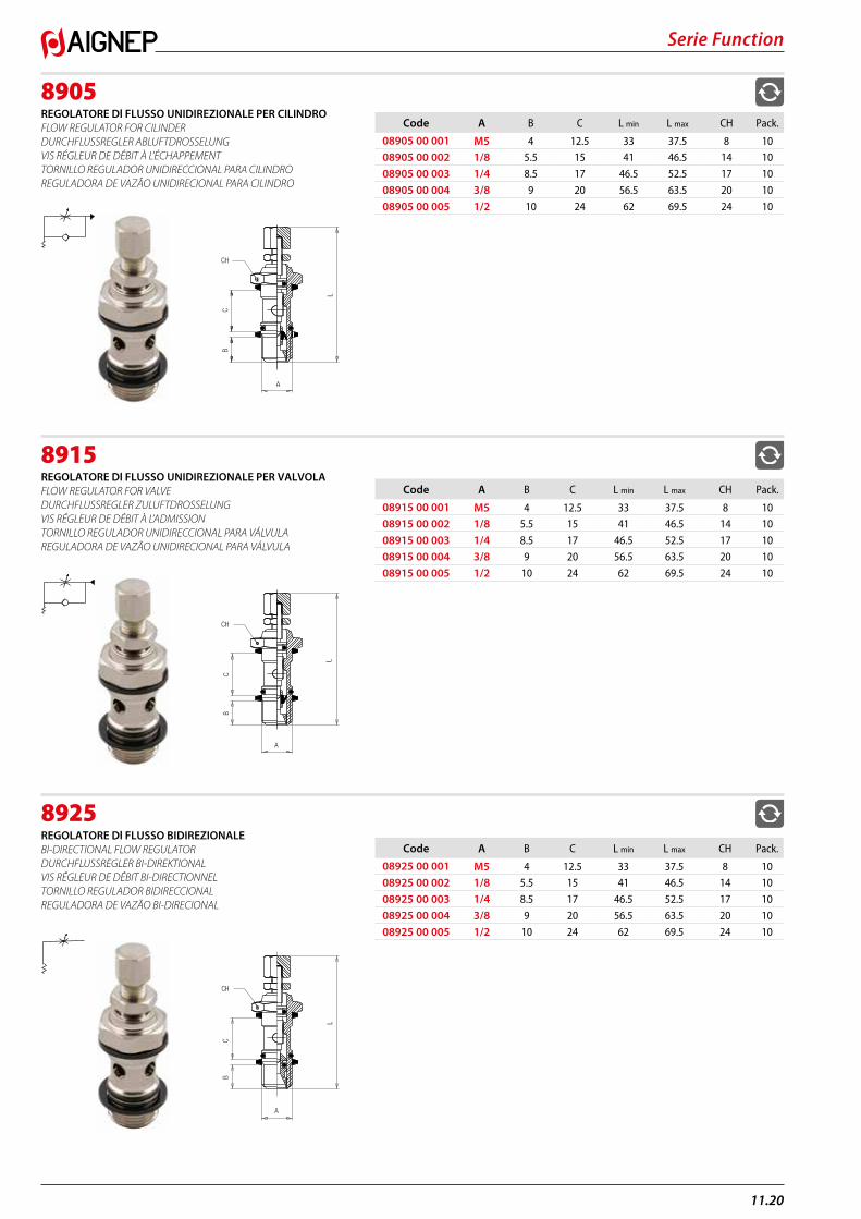
8905REGOLATORE Dl FLUSSO UNIDIREZIONALE PER CILINDRO FLOW REGULATOR FOR CILINDER DURCHFLUSSREGLER ABLUFTDROSSELUNG VIS RÉGLEUR DE DÉBIT À L’ÉCHAPPEMENT TORNILLO REGULADOR UNIDIRECCIONAL PARA CILINDRO REGULADORA DE VAZÃO UNIDIRECIONAL PARA CILINDRO
8915REGOLATORE Dl FLUSSO UNIDIREZIONALE PER VALVOLA FLOW REGULATOR FOR VALVE DURCHFLUSSREGLER ZULUFTDROSSELUNG VIS RÉGLEUR DE DÉBIT À L’ADMISSION TORNILLO REGULADOR UNIDIRECCIONAL PARA VÁLVULA REGULADORA DE VAZÃO UNIDIRECIONAL PARA VÁLVULA
8925REGOLATORE Dl FLUSSO BIDIREZIONALE Bl-DIRECTIONAL FLOW REGULATOR DURCHFLUSSREGLER BI-DIREKTIONAL VIS RÉGLEUR DE DÉBIT BI-DIRECTIONNEL TORNILLO REGULADOR BIDIRECCIONAL REGULADORA DE VAZÃO BI-DIRECIONAL
Code A B C L min L max CH Pack.
08905 00 001 M5 4 12.5 33 37.5 8 1008905 00 002 1/8 5.5 15 41 46.5 14 10
08905 00 003 1/4 8.5 17 46.5 52.5 17 10
08905 00 004 3/8 9 20 56.5 63.5 20 10
08905 00 005 1/2 10 24 62 69.5 24 10
A
B
L
C
CH
Code A B C L min L max CH Pack.
08915 00 001 M5 4 12.5 33 37.5 8 1008915 00 002 1/8 5.5 15 41 46.5 14 10
08915 00 003 1/4 8.5 17 46.5 52.5 17 10
08915 00 004 3/8 9 20 56.5 63.5 20 10
08915 00 005 1/2 10 24 62 69.5 24 10
A
CB
L
CH
Code A B C L min L max CH Pack.
08925 00 001 M5 4 12.5 33 37.5 8 1008925 00 002 1/8 5.5 15 41 46.5 14 10
08925 00 003 1/4 8.5 17 46.5 52.5 17 10
08925 00 004 3/8 9 20 56.5 63.5 20 10
08925 00 005 1/2 10 24 62 69.5 24 10
A
CH
L
BC
Serie Function
11.21
PTESFR
DEGBIT
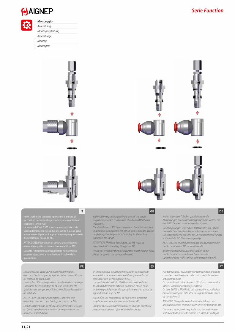
Nelle tabelle che seguono riportiamo le misure di raccordi ad occhiello che possono essere montati con i regolatori serie 8900.Le misure dell’art. 1500 sono state estrapolate dalla tabella dell’articolo stesso. Gli art. 50505 e 57505 sono invece raccordi prodotti appositamente per questa serie di regolatori di flusso da M5.
ATTENZIONE: I Regolatori di portata da M5 devono essere accoppiati con i raccordi orientabili da M6.
Durante l’inserimento del regolatore nell’occhiello prestare attenzione a non rivoltare il labbro della guarnizione.
Les tableaux ci-dessous indiquent les dimensions des corps banjo simples, qui peu vent être assemblés avec les régleurs de débit 8900.Les articles 1500 correspondent aux dimensions du corps standards. Les corps banjo de la série 50505 ont été spécialement conçus pour être assemblés sur les régleurs de débit M5.
ATTENTION: Les régleurs de débit M5 doivent être assemblés avec un corps banjo pour une vis de M6.
Lors de l’assemblage du RÉGLEUR de débit dans le corps du banjo, veuillez faire attention de ne pas blesser ou retourner le joint à lèvre.
In the following tables specify the sizes of the single banjo bodies which can be assembled with 8900 Series regulators.The sizes the art. 1500 have been taken from the standard single banjo bodies table. Art. 50505 and 57505 are special single banjo bodies produced suitably for the of flow regulators M5 range.
ATTENTION: The Flow Regulators size M5 must be assembled with orienting fittings size M6.
When you assemble the flow regulator into the banjo body, please be careful not damage the seal.
En las tablas que siguen a continuación se especifican las medidas de los racores orientables que pueden ser montados con los reguladores 8900.Las medidas del artículo 1500 han sido extrapoladas de la tabla del mismo artículo. El artículo 50505 es un artículo especial producido a propósito para esta serie de reguladores de flujo de M5.
ATENCIÓN: Los reguladores de flujo de M5 deben ser acoplados con los racores orientables de M6.
Durante la inserción del regulador en el anillo orientable prestar atención a no girar el labio de la junta.
In den folgenden Tabellen spezifizieren wir die Abmessungen der einfachen Ringanschlüsse, welche mit den 8900 Drosseln montiert werden können.
Die Abmessungen vom Artikel 1500 wurden der Tabelle des einfa chen Standard-Ringanschlusses entnommen. Die Ringanschlüsse der Serie 50505 wurden speziell für das Sortiment der M5 Drosseln angefertigt.
ACHTUNG:Die Durchflussregler mit M5 müssen mit den Hohlschrauben für M6 montiert werden.
Bei der Montage des Durchflussreglers in die Hohlschraube ist darauf zu achten, dass die Lippendichtung nicht verletzt oder umgedreht wird.
Nas tabelas que seguem apresentamos os tamanhos de conexões orientáveis que podem ser montados com os reguladoras 8900. Os tamanhos da série de cód. 1500 são os mesmos das tabelas referentes aos banjos padrão. Os cód. 50505 e 57505 são por sua vez itens produzidos especialmente para esta série de reguladoras de vazão de tamanho M5.
ATENÇÃO: Os reguladoras de vazão M5 devem ser acoplados comas conexões orientáveis de tamanho M6.
Durante a inserção do reguladora no haste do banjo tenha cuidado para não danificar o lábio da vedação.
Montaggio
Assembling
Montageanleitung
Assemblage
Montaje
Montagem
11.22
Serie Function
1500ANELLO ORIENTABILE A L (PER REGOLATORI Dl PORTATA M5) SINGLE BANJO BODY (ADJUSTABLE RESTRICTOR VALVES M5) RINGANSCHLUSS (FÜR DURCHFLUSSREGLER M5) CORPS BANJO SIMPLE (POUR RÉGLEUR DE DÉBIT M5) ANILLO ORIENTABLE SIMPLE (PARA REGULADOR DE CAUDAL M5) ANEL ORIENTÁVEL EM “L” (PARA REGULADORAS DE VAZÃO M5)
1500ANELLO ORIENTABILE A L SINGLE BANJO BODY RINGANSCHLUSS CORPS BANJO SIMPLE ANILLO ORIENTABLE SIMPLE ANEL ORIENTÁVEL EM “L”
50505ANELLO ORIENTABILE A L (PER REGOLATORI DI PORTATA M5) SINGLE BANJO BODY (ADJUSTABLE RESTRICTOR VALVES M5) RINGANSCHLUSS (FÜR DURCHFLUSSREGLER M5) CORPS BANJO SIMPLE (POUR RÉGLEUR DE DÉBIT M5) ANILLO ORIENTABLE SIMPLE (PARA REGULADOR DE CAUDAL DE M5) ANEL ORIENTÁVEL EM “L” (PARA REGULADORAS DE VAZÃO M5)
50500ANELLO ORIENTABILE A L SINGLE BANJO BODY RINGANSCHLUSS CORPS BANJO SIMPLE ANILLO ORIENTABLE SIMPLE ANEL ORIENTÁVEL EM “L”
Code Tube A D S L Pack.
01500 00 002 4/2.7 M6 9 12.5 21.5 1001500 00 007 6/4 M6 9 12.5 21.5 10
Questo articolo è prodotto appositamente per regolatori di portata da M5.This article has been produced suitably for the Adjustable Restrictor valves M5.Dieser Artikel ist speziell für den Durchflussregler mit M5 hergestellt.Ces articles sont fabriqués spécialement pour les régleurs M5.Este artículo se produce a propósito para los reguladores de flujo de M5.Este item é produzido especialmente para utilização nas válvulas de tamanho M5.
A
S
L
D
Code Tube A D S L Pack.
01500 00 003 4/2.7 1/8 14 15 22.5 1001500 00 005 5/3 1/8 14 15 22.5 10
01500 00 008 6/4 1/8 14 15 23 10
01500 00 009 6/4 1/4 18 17 25 10
01500 00 010 6/4 3/8 21 20 27 10
01500 00 011 8/6 1/8 14 15 24.5 10
01500 00 012 8/6 1/4 18 17 26 10
01500 00 013 8/6 3/8 21 20 27 10
01500 00 014 8/6 1/2 26 24 31 10
01500 00 015 10/8 1/8 14 15 27.5 10
01500 00 016 10/8 1/4 18 17 27.5 10
01500 00 017 10/8 3/8 21 20 30.5 10
01500 00 018 10/8 1/2 26 24 34 10
01500 00 019 12/10 3/8 21 20 31.5 10
01500 00 020 12/10 1/2 26 24 35 10
01500 00 021 15/12.5 1/2 26 24 36.5 10
S
A
D
L
Code Tube A B L D Pack.
50505 00 005 3 M6 12.5 19 10 1050505 00 001 4 M6 12.5 19 10 10
50505 00 003 5 M6 12.5 20 12.5 10
50505 00 004 6 M6 12.5 20.5 12.5 10
Questo articolo è prodotto appositamente per regolatori di portata da M5.This article has been produced suitably for the adjustable restrictor valves M5.Dieser Artikel ist speziell für den Durchflussregler mit M5 hergestellt.Ces articles sont fabriqués spécialement pour les régleurs M5.Este artículo se produce a propósito para los reguladores de flujo de M5.Este item é produzido especialmente para utilização nas válvulas de tamanho M5.B
L
A
D
Code Tube A B L CH D Pack.
50500 00 003 4 1/8 15 21 14 10 1050500 00 014 5 1/8 15 21.5 14 12.5 10
50500 00 015 5 1/4 17 24.5 18 12.5 10
50500 00 004 6 1/8 15 22 14 12.5 10
50500 00 005 6 1/4 17 25 18 12.5 10
50500 00 006 8 1/8 15 24 14 14 10
50500 00 007 8 1/4 17 26 18 14 10
50500 00 008 8 3/8 20 28 21 14 10
50500 00 009 10 1/4 17 29 18 17 10
50500 00 010 10 3/8 20 30.5 21 17 10
50500 00 012 12 3/8 20 32.5 21 21.5 10
50500 00 021 12 1/2 24 35 25 21.5 10
50500 00 022 14 1/2 24 35.5 25 21.5 10
D
A
B
L CH
Serie Function
11.23
57505ANELLO ORIENTABILE A L (PER REGOLATORI DI PORTATA M5) SINGLE BANJO BODY (ADJUSTABLE RESTRICTOR VALVES M5) RINGANSCHLUSS (FÜR DURCHFLUSSREGLER M5) CORPS BANJO SIMPLE (POUR RÉGLEUR DE DÉBIT M5) ANILLO ORIENTABLE SIMPLE (PARA REGULADOR DE CAUDAL DE M5) ANEL ORIENTÁVEL EM “L” (PARA REGULADORAS DE VAZÃO M5)
57500ANELLO ORIENTABILE A L SINGLE BANJO BODY RINGANSCHLUSS CORPS BANJO SIMPLE ANILLO ORIENTABLE SIMPLE ANEL ORIENTÁVEL EM “L”
89505ANELLO ORIENTABILE A L (PER REGOLATORI DI PORTATA M5) SINGLE BANJO BODY (ADJUSTABLE RESTRICTOR VALVES M5) RINGANSCHLUSS (FÜR DURCHFLUSSREGLER M5) CORPS BANJO SIMPLE (POUR RÉGLEUR DE DÉBIT M5) ANILLO ORIENTABLE SIMPLE (PARA REGULADOR DE CAUDAL DE M5) ANEL ORIENTÁVEL EM “L” (PARA REGULADORAS DE VAZÃO M5)
6090ANELLO ORIENTABILE A L FEMMINA FEMALE SINGLE BANJO BODY RINGANSCHLUSS INNENGEW CORPS BANJO TARAUDE ANILLO ORIENTABLE HEMBRA ANEL ORIENTÁVEL EM ”L” COM ROSCA FÊMEA
Code Tube A B L D Pack.
*57505 00 001 4 (5/32) M6 12.5 18.5 10.5 10 57505 00 003 5 M6 12.5 20 12.5 10
57505 00 004 6 M6 12.5 21.5 12.5 10
Questo articolo è prodotto appositamente per regolatori di portata da M5.This article has been produced suitably for the adjustable restrictor valves M5.Dieser Artikel ist speziell für den Durchflussregler mit M5 hergestellt.Ces articles sont fabriqués spécialement pour les régleurs M5.Este artículo se produce a propósito para los reguladores de flujo de M5.Este item é produzido especialmente para utilização nas válvulas de tamanho M5.
* Articolo in comune con serie 89000.* Item in common with series 89000.* Gegenstände gemeinsam mit Serie 89000.* Pour les produits en commun avec la série 89000.* Artículos en común con la serie 89000.* Código em comum com a série 89000.
B
L
A
D
Code Tube A B L CH D Pack.
57500 00 003 4 1/8 15 21 14 10 1057500 00 014 5 1/8 15 21.5 14 12.5 10
57500 00 015 5 1/4 17 24.5 18 12.5 10
57500 00 004 6 1/8 15 22 14 12.5 10
57500 00 005 6 1/4 17 25 18 12.5 10
57500 00 006 8 1/8 15 24 14 14 10
57500 00 007 8 1/4 17 26 18 14 10
57500 00 008 8 3/8 20 28 21 14 10
57500 00 009 10 1/4 17 29 18 17 10
57500 00 010 10 3/8 20 30.5 21 17 10
57500 00 012 12 3/8 20 32.5 21 21.5 10
57500 00 021 12 1/2 24 35 25 21.5 10
57500 00 022 14 1/2 24 35.5 25 21.5 10
D
A
B
L CH
Code Tube A B L D Pack.
*57505 00 001 5/32 (4) M6 12.5 18.5 10.5 10 89505 00 001 1/8 M6 12.5 16.5 10.5 10
89505 00 003 1/4 M6 12.5 21.5 12.5 10
Questo articolo è prodotto appositamente per Regolatori di Portata da M5.This article has been produced suitably for the Adjustable Restrictor valves M5.Dieser Artikel ist speziell für den Durchflussregler mit M5 hergestellt.Ces articles sont fabriqués spécialement pour les régleurs M5.Este artículo se produce a propósito para los reguladores de flujo de M5.Este item é produzido especialmente para utilização nas válvulas de tamanho M5.
* Articolo in comune con serie 57000.* Item in common with series 57000.* Gegenstände gemeinsam mit Serie 57000.* Pour les produits en commun avec la série 57000.* Artículos en común con la serie 57000.* Código em comum com a série 57000.
B
L
A
D
Code B A L S Pack.
06090 00 01 02 NB 1/8 10 16.5 15 1006090 00 01 03 NB 1/4 13 22 17 10
06090 00 01 04 NB 3/8 16.7 26 20 10
L
A
S
B
11.24
Serie Function
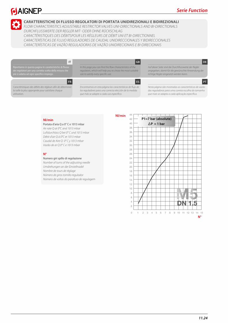
CARATTERISTICHE DI FLUSSO REGOLATORI DI PORTATA UNIDIREZIONALI E BIDIREZIONALI FLOW CHARACTERISTICS ADJUSTABLE RESTRICTOR VALVES UNI-DIRECTIONALS AND BI-DIRECTIONALS DURCHFLUSSWERTE DER REGLER MIT- ODER OHNE RÜCKSCHLAG CARACTÉRISTIQUES DES DÉBITSPOUR LES RÉGLEURS DE DÉBIT UNI ET BI-DIRECTIONNEL CARACTERÍSTICAS DE FLUJO REGULADORES DE CAUDAL UNIDIRECCIONALES Y BIDIRECCIONALES CARACTERÍSTICAS DE VAZÃO REGULADORAS DE VAZÃO UNIDIRECIONAIS E BI-DIRECIONAIS
Nl/minPortata d’aria Q a 0° C e 1013 mbar Air rate Q at 0°C and 1013 mbarLuftdurchlass Q bei 0° C und 1013 mbarDébit d’air Q à 0°C et 1013 mbarCaudal de Aire Q 0° C y 1013 mbarVazão de ar Q 0° C e 1013 mbar
N°Numero giri spillo di regolazioneNumber of turns of the adjiusting needleUmdrehungen an der EinstellnadelNombre de tours de réglageNúmero de giros tornillo reguladorNúmero de voltas do parafuso de regulagem
0 1 2 3 4 5 6 7 8 9 10 11 12 13 14 15
2
4
6
8
10
12
14
16
18
20
22
24
26
28
30
32
34
36
38
40
42
44
P1=7 bar (absolute)P = 1 bar
DN 1.5
Nl/min
N°
PTESFR
DEGBIT
Riportiamo in questa pagina le caratteristiche di flusso dei regolatori per una corretta scelta della misura che più si adatta ad ogni specifico impiego.
Caractéristiques des débits des régleurs afin de déterminer la taille la plus appropriée pour satisfaire chaque utilisation.
In this page you can find the flow characteristics of the regulators, which will help you to chose the most suitable size to satisfy every specific use.
Encontramos en esta página las características de flujo de los reguladores para una correcta elección de la medida que más se adapte a cada uso específico.
Auf dieser Seite sind die Durchflusswerte der Regler angegeben, damit für die gewünschte Anwendung der richtige Regler eingesetzt werden kann.
Nesta página são mostradas as características de vazão das reguladoras para uma correta escolha do tamanho que mais se adapta a cada aplicação específica.
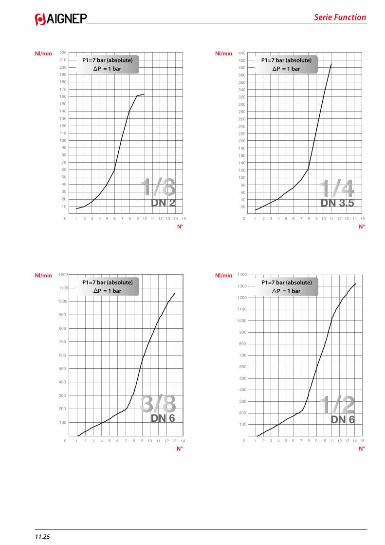
Serie Function
11.25
10
20
30
40
50
60
70
80
90
100
110
120
130
140
150
160
170
180
190
200
210
220
0 1 2 3 4 5 6 7 8 9 10 11 12 13 14 15
P1=7 bar (absolute)P = 1 bar
DN 2
0 1 2 3 4 5 6 7 8 9 10 11 12 13 14
P1=7 bar (absolute)P = 1 bar
100
200
300
400
500
600
700
800
900
1000
1100
1200
DN 6
P1=7 bar (absolute)P = 1 bar
0 1 2 3 4 5 6 7 8 9 10 11 12 13 14 15
1000
1100
1200
1300
1400
100
200
300
400
500
600
700
800
900
DN 6
0 1 2 3 4 5 6 7 8 9 10 11 12 13 14 15
P1=7 bar (absolute)P = 1 bar
20
40
60
80
100
120
140
160
180
200
220
240
260
280
300
320
340
360
380
400
420
440
DN 3.5
Nl/min
Nl/min
Nl/min
Nl/min
N°
N°
N°
N°
11.26
Serie Function
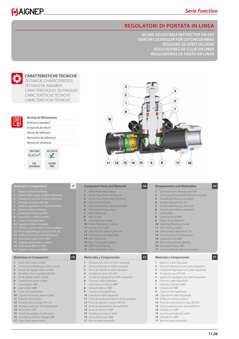
REGOLATORI DI PORTATA IN LINEAIN LINE ADJUSTABLE RESTRICTOR VALVES
DURCHFLUSSREGLER FÜR LEITUNGSEINBAURÉGLEURS DE DÉBIT EN LIGNE
REGULADORES DE FLUJO EN LINEAREGULADORAS DE VAZÃO EM LINHA
PTESFR
DEGBITMateriali e Componenti
1 Nipplo in Ottone Nichelato2 Ghiera di Bloccaggio in Ottone Nichelato3 Pomolo di comando in Ottone Nichelato4 Rondella in acciaio AISI 3045 Spillo di regolazione in Ottone Nichelato6 Ghiera in ottone nichelato7 Guarnizione O-Ring in NBR8 Guarnizione a labbro in NBR9 Corpo in tecnopolimero10 Capsula in ottone nichelato11 Spintore sgancio tubo in resina acetalica12 Pinza d’aggraffaggio in acciaio AISI 30113 Anello di sicurezza in tecnopolimero14 Guarnizione sagomata in NBR15 Supporto guida tubo in ottone16 Guarnizione filetto in NBR17 Basetta in ottone nichelato
Matériaux et Composants
1 Corps fileté: laiton nickelé2 Contre écrou de blocage: laiton nickelé3 Bouton de réglage: laiton nickelé4 Rondelle: acier inoxydable AISI 3045 Vis de réglage: laiton nickelé6 Contre écrou: laiton nickelé7 Joint torique: NBR 8 Joint à lèvre: NBR9 Corps: technopolymère 10 Capsule de retenue: laiton nickelé11 Poussoir: résine acétal12 Rondelle d’accrochage: AISI 30113 Anneau de sécurité: Technopolymère 14 Joint à lèvre: NBR15 Douille de guidage du tube: laiton16 Joint d’étanchéité du filetage: NBR17 Corps fileté: laiton nickelé
Component Parts and Materials
1 Nickel-Plated Brass Nipple2 Nickel-Plated Brass Locking nut3 Nickel-Plated Brass Adjusting Knob4 Steel AISI 304 Washer5 Nickel-Plated Brass Adjusting needle6 Nickel-plated brass sleeve7 NBR O-Ring seal8 NBR Lip seal9 Technopoymeric Body10 Nickel-Plated Brass Capsule11 Acetalic resin Collet12 Steel AISI 301 Clamping Washer13 Technopoymeric safety Ring14 NBR molded seal15 Brass Tube-guide Support16 NBR Thread Packing17 Nickel-Plated Brass Base
Materiales y Componentes
1 Manguito de unión en latón niquelado2 Tuerca de blocaje en latón niquelado3 Pomo de mando en latón niquelado4 Arandela en acero AISI 3045 Tornillo de regulación en latón niquelado6 Tuerca en latón niquelado7 Junta tórica O-Ring en NBR8 Junta de labio en NBR9 Cuerpo en tecnopolímero10 Cápsula en latón niquelado11 Anillo de extracción tubo en resina acetálica12 Pinza de sujeción en acero AISI 30113 Anillo de seguridad en tecnopolímero14 Junta de forma en NBR15 Soporte guia tubo en latón16 Junta de forma en NBR17 Base en latón niquelado
Komponenten und Materialien
1 Gewindestutzen Messing vernickelt2 Sicherungs-Kontermutter Messing vernickelt3 Einstellknopf Messing vernickelt4 Scheibe Edelstahl AISI 3045 Einstellnadel Messing vernickelt6 Kontermutter Messing vernickelt7 O-Ring NBR 8 Lippendichtung NBR9 Körper Technopolymer 10 Haltering Messing vernickelt11 Rohr Lösering Acetal12 Zahnscheibe Edelstahl AISI 30113 Sicherungsring Technopolymer 14 Lippendichtung NBR15 Rohr Führungshülse Messing16 Gewindedichtung NBR17 Einschraubkörper Messing vernickelt
Materiais e Componentes
1 Niple em Latão Niquelado2 Porca de Travamento em Latão Niquelado3 Cabeça de Regulagem em Latão Niquelado4 Arruela em aço AISI 3045 Agulha de regulagem em Latão Niquelado6 Poca em Latão Niquelado7 Vedação O-Ring en NBR8 Vedação em NBR9 Corpo em tecnopolímero10 Cápsula em Latão Niquelado11 Anilha em resina acetálica12 Pinça de travamento em aço AISI 30113 Anel de segurança em tecnopolímero14 Vedação em NBR15 Suporte guia tubo em Latão16 Vedação em NBR17 Base em Latão niquelado
CARATTERISTICHE TECNICHE TECHNICAL CHARACTERISTICS TECHNISCHE ANGABEN CARACTÉRISTIQUES TECHNIQUES CARACTERÍSTICAS TÉCNICAS CARACTERÍSTICAS TÉCNICAS
Norma di Riferimento
Reference standard
Entspricht der Norm
Norme de référence
Normativa de referencia
Norma de referência
1907/2006 2011/65/CE
PED 2014/68/UE
SILICON FREE
Serie Function
11.27
1 bar (0.1 MPa)
10 bar (1 MPa)
Fluidi compatibili Aria compressa
Fluids Compressed air
Geeignete Medien Druckluft
Fluides compatibles Air comprimé
Fluidos compatibles Aire comprimido
Fluidos compatíveis Ar comprimido
Pressioni
Pressures
Druckbereich
Pressions
Presiones
Pressões
Bar
PTESFR
DEGBITTubi di Collegamento
Tubi in materiale plastico:PA6, PA11, PA12, Polietilene, *Poliuretano, PTFE, FEP.
*Per tubi in Poliuretano é consigliata una durezza di 98 shore.
Tubes Conseillés
Tubes plastiques:PA6, PA11, PA12, Polyéthylène, *Polyuréthane, PTFE, FEP.
*Pour les tubes en polyuréthane, il est conseillé une dureté de 98 Shore.
Connection Tubes
Plastic tubes:PA6, PA11, PA12, Polyethylene, *Polyurethane, PTFE, FEP.
*For Polyurethane hoses it is required a minimum hardness of 98 shore.
Tubos de Conexión
Tubos en material plástico:PA6, PA11, PA 12, Polietileno, *Poliuretano, PTFE, FEP.
*Para tubos en poliuretano es aconsejada una dureza de 98 shore.
Geeignete Rohre
Kunststoffrohre:PA6, PA11, PA 12, Polyethylene, *Polyurethan, PTFE, FEP.
*Für Polyurethan Rohre ist eine Härte von 98 Shore empfohlen.
Tubos de Conexão
Tubos em material plástico:PA6, PA11, PA12, Polietileno, *Poliuretano, PTFE, FEP.
*Para tubos em Poliuretano é requerida uma dureza de 98 shore.
- 20 °C+ 80 °C
Temperature
Temperatures
Temperatur
Températures
Temperaturas
Temperaturas
DEGBITFilettatura
Gas conica “UNIVERSAL SHORT”.
Threads
“UNIVERSAL SHORT” Tapered thread.
Gewindearten
Konisches Gewinde “UNIVERSAL SHORT”.
PTESFRFiletages
Filetage conique “UNIVERSAL SHORT”.
Roscas
Gas cónica “UNIVERSAL SHORT”.
Roscas
Gas conica “UNIVERSAL SHORT”.
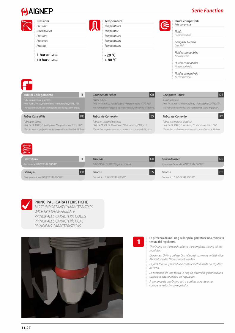
PRINCIPALI CARATTERISTICHE MOST IMPORTANT CHARACTERISTICS WICHTIGSTEN MERKMALE PRINCIPALES CARACTERISTIQUES PRINCIPALES CARACTERÍSTICAS PRINCIPAIS CARACTERÍSTICAS
La presenza di un O-ring sullo spillo, garantisce una completa tenuta del regolatore.
The O-ring on the needle, allows the complete, sealing of the regulator.
Durch den O-Ring auf der Einstellnadel kann eine vollständige Abdichtung des Reglers erzielt werden.
Le joint torique garantit une complète étanchéité du réguleur de débit.
La presencia de una tórica O-ring en el tornillo, garantiza una completa estanqueidad del regulador.
A presença de um O-ring sob a agulha, garante uma completa vedação do regulador.
11.28
Serie Function
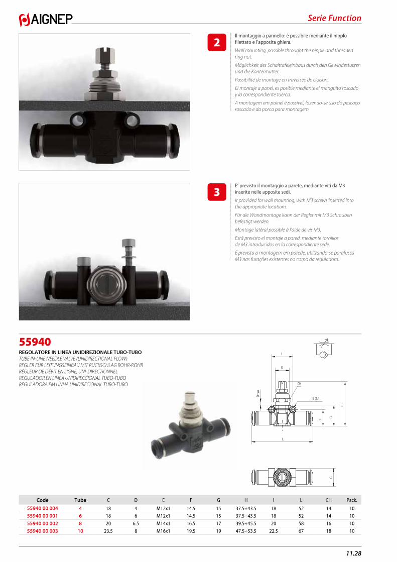
55940REGOLATORE IN LINEA UNIDIREZIONALE TUBO-TUBO TUBE IN-LINE NEEDLE VALVE (UNIDIRECTIONAL FLOW) REGLER FÜR LEITUNGSEINBAU MIT RÜCKSCHLAG ROHR-ROHR RÉGLEUR DE DÉBIT EN LIGNE, UNI-DIRECTIONNEL REGULADOR EN LINEA UNIDIRECCIONAL TUBO-TUBO REGULADORA EM LINHA UNIDIRECIONAL TUBO-TUBO
I
E
Ø 3,4
L
F C
H
Dmax
CH
G
Code Tube C D E F G H I L CH Pack.
55940 00 004 4 18 4 M12x1 14.5 15 37.5÷43.5 18 52 14 10 55940 00 001 6 18 6 M12x1 14.5 15 37.5÷43.5 18 52 14 10
55940 00 002 8 20 6.5 M14x1 16.5 17 39.5÷45.5 20 58 16 10
55940 00 003 10 23.5 8 M16x1 19.5 19 47.5÷53.5 22.5 67 18 10
Il montaggio a pannello: è possibile mediante il nipplo filettato e l’apposita ghiera.
Wall mounting, possible throught the nipple and threaded ring nut.
Möglichkeit des Schalttafeleinbaus durch den Gewindestutzen und die Kontermutter.
Possibilité de montage en traversée de cloison.
El montaje a panel, es posible mediante el manguito roscado y la correspondiente tuerca.
A montagem em painel é possível, fazendo-se uso do pescoço roscado e da porca para montagem.
E’ previsto il montaggio a parete, mediante viti da M3 inserite nelle apposite sedi.
It provided for wall mounting, with M3 screws inserted into the appropriate locations.
Für die Wandmontage kann der Regler mit M3 Schrauben befestigt werden.
Montage latéral possible à l’aide de vis M3.
Está previsto el montaje a pared, mediante tornillos de M3 introducidos en la correspondiente sede.
É prevista a montagem em parede, utilizando-se parafusos M3 nas furações existentes no corpo da reguladora.
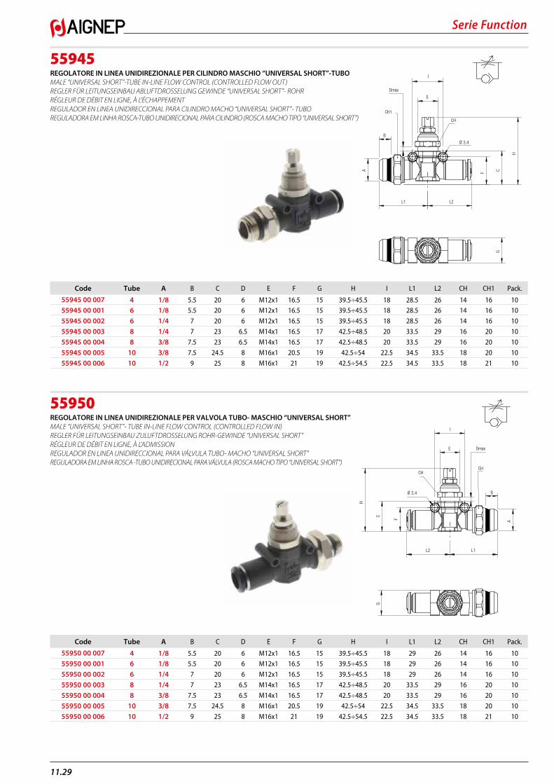
Serie Function
11.29
55945REGOLATORE IN LINEA UNIDIREZIONALE PER CILINDRO MASCHIO “UNIVERSAL SHORT”-TUBO MALE “UNIVERSAL SHORT”-TUBE IN-LINE FLOW CONTROL (CONTROLLED FLOW OUT) REGLER FÜR LEITUNGSEINBAU ABLUFTDROSSELUNG GEWINDE “UNIVERSAL SHORT”- ROHR RÉGLEUR DE DÉBIT EN LIGNE, À L’ÉCHAPPEMENT REGULADOR EN LINEA UNIDIRECCIONAL PARA CILINDRO MACHO “UNIVERSAL SHORT”- TUBO REGULADORA EM LINHA ROSCA-TUBO UNIDIRECIONAL PARA CILINDRO (ROSCA MACHO TIPO “UNIVERSAL SHORT”)
55950REGOLATORE IN LINEA UNIDIREZIONALE PER VALVOLA TUBO- MASCHIO “UNIVERSAL SHORT” MALE “UNIVERSAL SHORT”- TUBE IN-LINE FLOW CONTROL (CONTROLLED FLOW IN) REGLER FÜR LEITUNGSEINBAU ZULUFTDROSSELUNG ROHR-GEWINDE “UNIVERSAL SHORT” RÉGLEUR DE DÉBIT EN LIGNE, À L’ADMISSION REGULADOR EN LINEA UNIDIRECCIONAL PARA VÁLVULA TUBO- MACHO “UNIVERSAL SHORT” REGULADORA EM LINHA ROSCA -TUBO UNIDIRECIONAL PARA VÁLVULA (ROSCA MACHO TIPO “UNIVERSAL SHORT”)
I
L1 L2
F C
H
E
Ø 3,4
A
Dmax
B
CH
CH1
G
Code Tube A B C D E F G H I L1 L2 CH CH1 Pack.
55945 00 007 4 1/8 5.5 20 6 M12x1 16.5 15 39.5÷45.5 18 28.5 26 14 16 1055945 00 001 6 1/8 5.5 20 6 M12x1 16.5 15 39.5÷45.5 18 28.5 26 14 16 10
55945 00 002 6 1/4 7 20 6 M12x1 16.5 15 39.5÷45.5 18 28.5 26 14 16 10
55945 00 003 8 1/4 7 23 6.5 M14x1 16.5 17 42.5÷48.5 20 33.5 29 16 20 10
55945 00 004 8 3/8 7.5 23 6.5 M14x1 16.5 17 42.5÷48.5 20 33.5 29 16 20 10
55945 00 005 10 3/8 7.5 24.5 8 M16x1 20.5 19 42.5÷54 22.5 34.5 33.5 18 20 10
55945 00 006 10 1/2 9 25 8 M16x1 21 19 42.5÷54.5 22.5 34.5 33.5 18 21 10
I
E
F
C
H
A
Ø 3,4
L1L2
Dmax
B
CH CH
G
Code Tube A B C D E F G H I L1 L2 CH CH1 Pack.
55950 00 007 4 1/8 5.5 20 6 M12x1 16.5 15 39.5÷45.5 18 29 26 14 16 1055950 00 001 6 1/8 5.5 20 6 M12x1 16.5 15 39.5÷45.5 18 29 26 14 16 10
55950 00 002 6 1/4 7 20 6 M12x1 16.5 15 39.5÷45.5 18 29 26 14 16 10
55950 00 003 8 1/4 7 23 6.5 M14x1 16.5 17 42.5÷48.5 20 33.5 29 16 20 10
55950 00 004 8 3/8 7.5 23 6.5 M14x1 16.5 17 42.5÷48.5 20 33.5 29 16 20 10
55950 00 005 10 3/8 7.5 24.5 8 M16x1 20.5 19 42.5÷54 22.5 34.5 33.5 18 20 10
55950 00 006 10 1/2 9 25 8 M16x1 21 19 42.5÷54.5 22.5 34.5 33.5 18 21 10

11.30
Serie Function
55955REGOLATORE IN LINEA BIDIREZIONALE TUBO-TUBO TUBE IN-LINE NEEDLE VALVE (BIDIRECTIONAL FLOW) REGLER FÜR LEITUNGSEINBAU BI-DIREKTIONAL ROHR-ROHR RÉGLEUR DE DÉBIT EN LIGNE, BI-DIRECTIONNEL REGULADOR EN LINEA BIDIRECCIONAL TUBO-TUBO REGULADORA EM LINHA BI-DIRECIONAL TUBO-TUBO
55960REGOLATORE IN LINEA BIDIREZIONALE MASCHIO “UNIVERSAL SHORT”- TUBO MALE “UNIVERSAL SHORT” - TUBE IN-LINE FLOW CONTROL (BIDIRECTIONAL FLOW) REGLER FÜR LEITUNGSEINBAU BI-DIREKTIONAL GEWINDE “UNIVERSAL SHORT”- ROHR RÉGLEUR DE DÉBIT EN LIGNE, BI-DIRECTIONNEL “UNIVERSAL SHORT” REGULADOR EN LINEA BIDIRECCIONAL MACHO “UNIVERSAL SHORT” - TUBO REGULADORA EM LINHA ROSCA-TUBO BI-DIRECIONAL PARA CILINDRO (ROSCA MACHO TIPO “UNIVERSAL SHORT”)
I
E
Ø 3,4
L
F C
H
Dmax
CH
G
Code Tube C D E F G H I L CH Pack.
55955 00 004 4 18 6 M12x1 14.5 15 37.5÷43.5 18 52 14 1055955 00 001 6 18 6 M12x1 14.5 15 37.5÷43.5 18 52 14 10
55955 00 002 8 20 6.5 M14x1 16.5 17 39.5÷45.5 20 58 16 10
55955 00 003 10 23.5 8 M16x1 19.5 19 47.5÷53.5 22.5 67 18 10
I
L1 L2
F C
H
E
Ø 3,4
A
Dmax
B
CH
CH1
G
Code Tube A B C D E F G H I L1 L2 CH CH1 Pack.
55960 00 007 4 1/8 5.5 20 6 M12x1 16.5 15 39.5÷45.5 18 28.5 26 14 16 1055960 00 001 6 1/8 5.5 20 6 M12x1 16.5 15 39.5÷45.5 18 28.5 26 14 16 10
55960 00 002 6 1/4 7 20 6 M12x1 16.5 15 39.5÷45.5 18 28.5 26 14 16 10
55960 00 003 8 1/4 7 23 6.5 M14x1 16.5 17 42.5÷48.5 20 33.5 29 16 20 10
55960 00 004 8 3/8 7.5 23 6.5 M14x1 16.5 17 42.5÷48.5 20 33.5 29 16 20 10
55960 00 005 10 3/8 7.5 24.5 8 M16x1 20.5 19 42.5÷54 22.5 34.5 33.5 18 20 10
55960 00 006 10 1/2 9 25 8 M16x1 21 19 42.5÷54.5 22.5 34.5 33.5 18 21 10
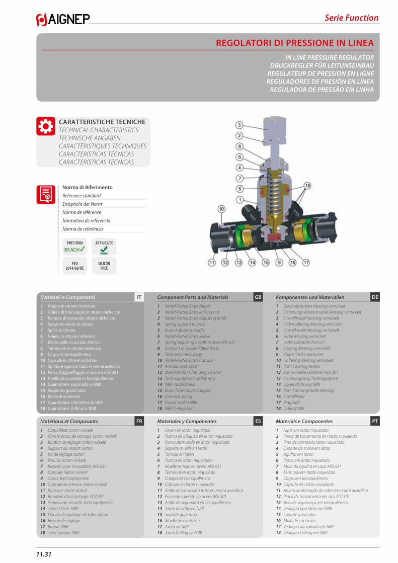
Serie Function
11.31
REGOLATORI DI PRESSIONE IN LINEAIN LINE PRESSURE REGULATOR
DRUCKREGLER FÜR LEITUNSEINBAUREGULATEUR DE PRESSION EN LIGNEREGULADORES DE PRESIÓN EN LÍNEA
REGULADOR DE PRESSÃO EM LINHA
PTESFR
DEGBITMateriali e Componenti
1 Nipplo in ottone nichelato2 Ghiera di bloccaggio in ottone nichelato3 Pomolo di comando ottone nichelato4 Supporto molla in ottone5 Spillo in ottone 6 Ghiera in ottone nichelato7 Molla spillo in acciaio AISI 6318 Terminale in ottone nichelato 9 Corpo in tecnopolimero10 Capsula in ottone nichelato11 Spintore sgancio tubo in resina acetalica12 Pinza d’aggraffaggio in acciaio AISI 30113 Anello di sicurezza in tecnopolimero14 Guarnizione sagomata in NBR15 Supporto guida tubo16 Molla di contrasto17 Guarnizione a fiorellino in NBR18 Guarnizione O-Ring in NBR
Matériaux et Composants
1 Corps fileté: laiton nickelé2 Contre écrou de blocage: laiton nickelé3 Bouton de réglage: laiton nickelé4 Support du ressort: laiton5 Vis de réglage: laiton6 Douille: laiton nickelé7 Ressort: acier inoxydable AISI 6318 Capsule: laiton nickelé 9 Corps: technopolymère10 Capsule de retenue: laiton nickelé11 Poussoir: résine acétal12 Rondelle d’accrochage: AISI 30113 Anneau de sécurité: technopolymère14 Joint à lèvre: NBR15 Douille de guidage du tube: laiton16 Ressort de réglage17 Bague: NBR18 Joint torique: NBR
Component Parts and Materials
1 Nickel-Plated Brass Nipple2 Nickel-Plated Brass locking nut3 Nickel-Plated Brass Adjusting Knob4 Spring support in brass5 Brass Adjusting needle6 Nickel-Plated Brass Sleeve7 Spring Adjusting needle in Steel AISI 6318 End part in Nickel-Plated Brass 9 Techopoymeric Body10 Nickel-Plated Brass Capsule11 Acetalic resin collet12 Steel AISI 301 Clamping Washer13 Technopolymeric safety ring14 NBR molded Seal15 Brass Tube-Guide Support16 Contrast spring17 Flower seal in NBR18 NBR O-Ring seal
Materiales y Componentes
1 Unión en latón niquelado 2 Tuerca de bloqueo en latón niquelado 3 Pomo de mando en latón niquelado 4 Soporte muelle en latón 5 Tornillo en latón 6 Tuerca en latón niquelado 7 Muelle tornillo en acero AISI 631 8 Terminal en latón niquelado 9 Cuerpo en tecnopolímero 10 Cápsula en latón niquelado 11 Anillo de extracción tubo en resina acetálica 12 Pinza de sujeción en acero AISI 301 13 Anillo de seguridad en tecnopolímero 14 Junta de labio en NBR 15 Soporte guía tubo 16 Muelle de contraste 17 Junta en NBR 18 Junta O-Ring en NBR
Komponenten und Materialien
1 Gewindestutzen Messing vernickelt2 Sicherungs-Kontermutter Messing vernickelt3 Einstellknopf Messing vernickelt4 Federhaltering Messing vernickelt5 Einstellnadel Messing vernickelt 6 Hülse Messing vernickelt7 Feder Edelstahl AISI 6318 Endring Messing vernickelt 9 Körper Technopolymer10 Haltering Messing vernickelt11 Rohr Lösering Acetal12 Zahnscheibe Edelstahl AISI 30113 Sicherungsring Technopolymer14 Lippendichtung NBR15 Rohr Führungshülse Messing16 Einstellfeder17 Ring NBR18 O-Ring NBR
Materiais e Componentes
1 Niple em latão niquelado 2 Porca de travamento em latão niquelado 3 Pino de comando latão niquelado 4 Suporte da mola em latão 5 Agulha em latão 6 Porca em latão niquelado 7 Mola da agulha em aço AISI 631 8 Terminal em latão niquelado 9 Corpo em tecnopolimero 10 Cápsula em latão niquelado 11 Anilha de liberação de tubo em resina acetálica 12 Pinça de travamento em aço AISI 301 13 Anel de segurança em tenopolímero 14 Vedação tipo lábio em NBR 15 Suporte guia tubo 16 Mola de contraste 17 Vedação da válvula em NBR 18 Vedação O-Ring em NBR
CARATTERISTICHE TECNICHE TECHNICAL CHARACTERISTICS TECHNISCHE ANGABEN CARACTÉRISTIQUES TECHNIQUES CARACTERÍSTICAS TÉCNICAS CARACTERÍSTICAS TÉCNICAS
Norma di Riferimento
Reference standard
Entspricht der Norm
Norme de référence
Normativa de referencia
Norma de referência
1907/2006 2011/65/CE
PED 2014/68/UE
SILICON FREE
11.32
Serie Function
PTESFR
DEGBITTubi di Collegamento
Tubi in materiale plastico:PA6, PA11, PA12, Polietilene, *Poliuretano, PTFE, FEP.
*Per tubi in Poliuretano é consigliata una durezza di 98 shore.
Tubes Conseillés
Tubes plastiques:PA6, PA11, PA12, Polyéthylène, *Polyuréthane, PTFE, FEP.
*Pour les tubes en polyuréthane, il est conseillé une dureté de 98 Shore.
Connection Tubes
Plastic tubes:PA6, PA11, PA12, Polyethylene, *Polyurethane, PTFE, FEP.
*For Polyurethane hoses it is required a minimum hardness of 98 shore.
Tubos de Conexión
Tubos en material plástico:PA6, PA11, PA 12, Polietileno, *Poliuretano, PTFE, FEP.
*Para tubos en poliuretano es aconsejada una dureza de 98 shore.
Geeignete Rohre
Kunststoffrohre:PA6, PA11, PA 12, Polyethylene, *Polyurethan, PTFE, FEP.
*Für Polyurethan Rohre ist eine Härte von 98 Shore empfohlen.
Tubos de Conexão
Tubos em material plástico:PA6, PA11, PA12, Polietileno, *Poliuretano, PTFE, FEP.
*Para tubos em Poliuretano é requerida uma dureza de 98 shore.
DEGBITFilettatura
Gas conica “UNIVERSAL SHORT”.
Threads
“UNIVERSAL SHORT” Tapered thread.
Gewindearten
Konisches Gewinde “UNIVERSAL SHORT”.
PTESFRFiletages
Filetage conique “UNIVERSAL SHORT”.
Roscas
Gas cónica “UNIVERSAL SHORT”.
Roscas
Gas conica “UNIVERSAL SHORT”.
2 bar (0.2 MPa)
10 bar (1 MPa)
Fluidi compatibili Aria compressa
Fluids Compressed air
Geeignete Medien Druckluft
Fluides compatibles Air comprimé
Fluidos compatibles Aire comprimido
Fluidos compatíveis Ar comprimido
Pressioni di ingresso
Inlet Pressures
Eingangsdruck
Pression d’entrée
Presión de entrada
Pressão de entrada
Bar
- 20 °C+ 80 °C
Temperature
Temperatures
Temperatur
Températures
Temperaturas
Temperaturas
Impostare la pressione voluta sempre in salita.Set the pressure always uphill. Gewünschten Druck von 1 bar nach oben einstellen.Le réglage de la pression se fait toujours vers le haut.Ajustar la presión deseada siempre en subida.Regular a pressão desejada sempre na saída.
1 ÷ 8 bar (0.1 ÷ 0.8 MPa)
Campo di Regolazione
Regulation Range
Regelbereich
Plage de Réglage
Campo de Regulación
Campo de Regulagem
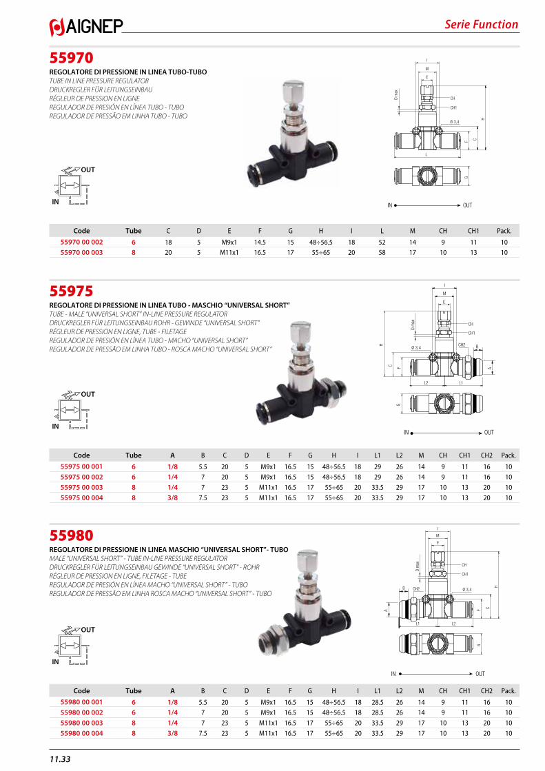
Serie Function
11.33
55970REGOLATORE DI PRESSIONE IN LINEA TUBO-TUBO TUBE IN LINE PRESSURE REGULATOR DRUCKREGLER FÜR LEITUNGSEINBAU RÉGLEUR DE PRESSION EN LIGNE REGULADOR DE PRESIÓN EN LÍNEA TUBO - TUBO REGULADOR DE PRESSÃO EM LINHA TUBO - TUBO
55975REGOLATORE DI PRESSIONE IN LINEA TUBO - MASCHIO “UNIVERSAL SHORT” TUBE - MALE “UNIVERSAL SHORT” IN-LINE PRESSURE REGULATOR DRUCKREGLER FÜR LEITUNGSEINBAU ROHR - GEWINDE “UNIVERSAL SHORT” RÉGLEUR DE PRESSION EN LIGNE, TUBE - FILETAGE REGULADOR DE PRESIÓN EN LÍNEA TUBO - MACHO “UNIVERSAL SHORT” REGULADOR DE PRESSÃO EM LINHA TUBO - ROSCA MACHO “UNIVERSAL SHORT”
55980REGOLATORE DI PRESSIONE IN LINEA MASCHIO “UNIVERSAL SHORT”- TUBO MALE “UNIVERSAL SHORT” - TUBE IN-LINE PRESSURE REGULATOR DRUCKREGLER FÜR LEITUNGSEINBAU GEWINDE “UNIVERSAL SHORT” - ROHR RÉGLEUR DE PRESSION EN LIGNE, FILETAGE - TUBE REGULADOR DE PRESIÓN EN LÍNEA MACHO “UNIVERSAL SHORT” - TUBO REGULADOR DE PRESSÃO EM LINHA ROSCA MACHO “UNIVERSAL SHORT” - TUBO
L
I
E
Ø 3,4
F C
H
G
D m
ax
CH
CH1
OUTIN
M
OUT
IN
Code Tube C D E F G H I L M CH CH1 Pack.
55970 00 002 6 18 5 M9x1 14.5 15 48÷56.5 18 52 14 9 11 1055970 00 003 8 20 5 M11x1 16.5 17 55÷65 20 58 17 10 13 10
I
E
Ø 3,4
F C
H
G
A
L2 L1
CH
CH1
BCH2
D m
ax
OUTIN
M
OUT
IN
Code Tube A B C D E F G H I L1 L2 M CH CH1 CH2 Pack.
55975 00 001 6 1/8 5.5 20 5 M9x1 16.5 15 48÷56.5 18 29 26 14 9 11 16 1055975 00 002 6 1/4 7 20 5 M9x1 16.5 15 48÷56.5 18 29 26 14 9 11 16 10
55975 00 003 8 1/4 7 23 5 M11x1 16.5 17 55÷65 20 33.5 29 17 10 13 20 10
55975 00 004 8 3/8 7.5 23 5 M11x1 16.5 17 55÷65 20 33.5 29 17 10 13 20 10
L2
I
E
Ø 3,4
F C
H
G
A
B CH2
L1
CH
CH1
D m
ax
OUTIN
M
OUT
IN
Code Tube A B C D E F G H I L1 L2 M CH CH1 CH2 Pack.
55980 00 001 6 1/8 5.5 20 5 M9x1 16.5 15 48÷56.5 18 28.5 26 14 9 11 16 1055980 00 002 6 1/4 7 20 5 M9x1 16.5 15 48÷56.5 18 28.5 26 14 9 11 16 10
55980 00 003 8 1/4 7 23 5 M11x1 16.5 17 55÷65 20 33.5 29 17 10 13 20 10
55980 00 004 8 3/8 7.5 23 5 M11x1 16.5 17 55÷65 20 33.5 29 17 10 13 20 10
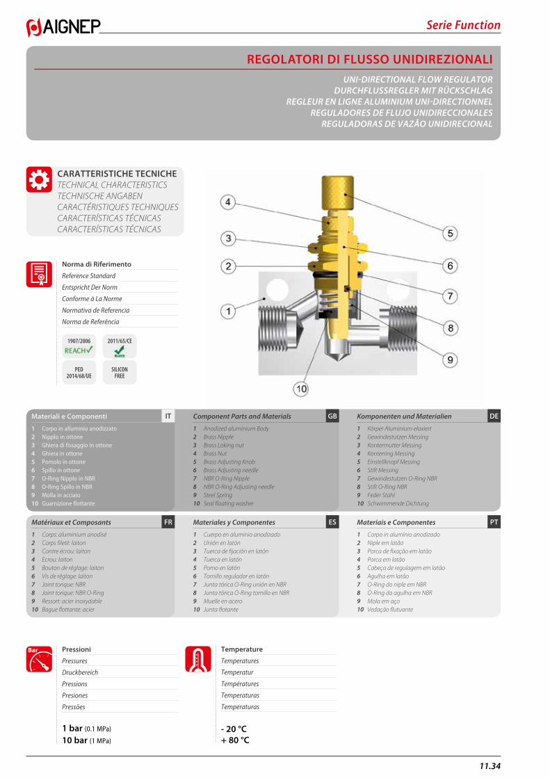
11.34
Serie Function
REGOLATORI DI FLUSSO UNIDIREZIONALIUNI-DIRECTIONAL FLOW REGULATOR
DURCHFLUSSREGLER MIT RÜCKSCHLAGREGLEUR EN LIGNE ALUMINIUM UNI-DIRECTIONNEL
REGULADORES DE FLUJO UNIDIRECCIONALESREGULADORAS DE VAZÃO UNIDIRECIONAL
CARATTERISTICHE TECNICHE TECHNICAL CHARACTERISTICS TECHNISCHE ANGABEN CARACTÉRISTIQUES TECHNIQUES CARACTERÍSTICAS TÉCNICAS CARACTERÍSTICAS TÉCNICAS
PTESFR
DEGBITMateriali e Componenti
1 Corpo in alluminio anodizzato2 Nipplo in ottone3 Ghiera di fissaggio in ottone4 Ghiera in ottone5 Pomolo in ottone6 Spillo in ottone7 O-Ring Nipplo in NBR8 O-Ring Spillo in NBR9 Molla in acciaio10 Guarnizione flottante
Matériaux et Composants
1 Corps: aluminium anodisé2 Corps fileté: laiton3 Contre écrou: laiton4 Ecrou: laiton5 Bouton de réglage: laiton6 Vis de réglage: laiton7 Joint torique: NBR8 Joint torique: NBR O-Ring9 Ressort: acier inoxydable10 Bague flottante: acier
Component Parts and Materials
1 Anodized aluminium Body2 Brass Nipple3 Brass Loking nut4 Brass Nut5 Brass Adjusting Knob6 Brass Adjusting needle7 NBR O-Ring Nipple8 NBR O-Ring Adjusting needle9 Steel Spring10 Seal floating washer
Materiales y Componentes
1 Cuerpo en aluminio anodizado 2 Unión en latón 3 Tuerca de fijación en latón 4 Tuerca en latón 5 Pomo en latón6 Tornillo regulador en latón7 Junta tórica O-Ring unión en NBR 8 Junta tórica O-Ring tornillo en NBR 9 Muelle en acero10 Junta flotante
Komponenten und Materialien
1 Körper Aluminium eloxiert2 Gewindestutzen Messing3 Kontermutter Messing4 Konterring Messing5 Einstellknopf Messing6 Stift Messing7 Gewindestutzen O-Ring NBR8 Stift O-Ring NBR9 Feder Stahl10 Schwimmende Dichtung
Materiais e Componentes
1 Corpo in alumínio anodizado 2 Niple em latão 3 Porca de fixação em latão 4 Porca em latão5 Cabeça de regulagem em latão 6 Agulha em latão7 O-Ring do niple em NBR8 O-Ring da agulha em NBR9 Mola em aço10 Vedação flutuante
1 bar (0.1 MPa)
10 bar (1 MPa)
Pressioni
Pressures
Druckbereich
Pressions
Presiones
Pressões
Bar
- 20 °C+ 80 °C
Temperature
Temperatures
Temperatur
Températures
Temperaturas
Temperaturas
Norma di Riferimento
Reference Standard
Entspricht Der Norm
Conforme à La Norme
Normativa de Referencia
Norma de Referência
1907/2006 2011/65/CE
PED 2014/68/UE
SILICON FREE
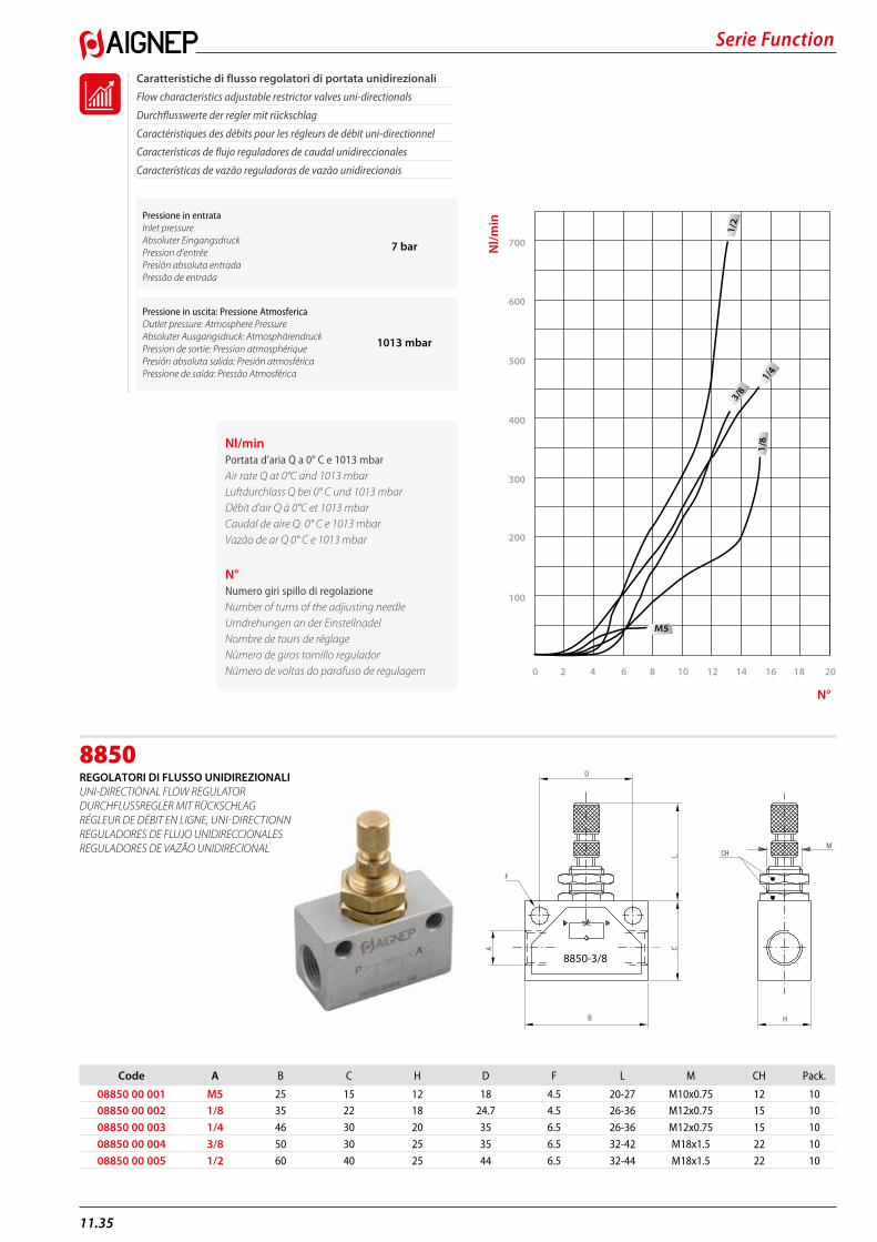
Serie Function
11.35
8850REGOLATORI DI FLUSSO UNIDIREZIONALI UNI-DIRECTIONAL FLOW REGULATOR DURCHFLUSSREGLER MIT RÜCKSCHLAG RÉGLEUR DE DÉBIT EN LIGNE, UNI-DIRECTIONNEL REGULADORES DE FLUJO UNIDIRECCIONALES REGULADORES DE VAZÃO UNIDIRECIONAL
D
F
A CL CH
H
M
B
8850-3/8
Code A B C H D F L M CH Pack.
08850 00 001 M5 25 15 12 18 4.5 20-27 M10x0.75 12 1008850 00 002 1/8 35 22 18 24.7 4.5 26-36 M12x0.75 15 10
08850 00 003 1/4 46 30 20 35 6.5 26-36 M12x0.75 15 10
08850 00 004 3/8 50 30 25 35 6.5 32-42 M18x1.5 22 10
08850 00 005 1/2 60 40 25 44 6.5 32-44 M18x1.5 22 10
Caratteristiche di flusso regolatori di portata unidirezionali
Flow characteristics adjustable restrictor valves uni-directionals
Durchflusswerte der regler mit rückschlag
Caractéristiques des débits pour les régleurs de débit uni-directionnel
Características de flujo reguladores de caudal unidireccionales
Características de vazão reguladoras de vazão unidirecionais
0
300
400
500
600
700
100
2 4 6 8 10 12 14 16 18 20
1/4
M5
3/8‘1
/2
200
1/8Nl/min
Portata d’aria Q a 0° C e 1013 mbar Air rate Q at 0°C and 1013 mbarLuftdurchlass Q bei 0° C und 1013 mbarDébit d’air Q à 0°C et 1013 mbarCaudal de aire Q 0° C e 1013 mbarVazão de ar Q 0° C e 1013 mbar
N°Numero giri spillo di regolazioneNumber of turns of the adjiusting needleUmdrehungen an der EinstellnadelNombre de tours de réglageNúmero de giros tornillo reguladorNúmero de voltas do parafuso de regulagem
Pressione in entrata Inlet pressureAbsoluter EingangsdruckPression d’entréePresión absoluta entradaPressão de entrada
7 bar
Pressione in uscita: Pressione AtmosfericaOutlet pressure: Atmosphere PressureAbsoluter Ausgangsdruck: AtmosphärendruckPression de sortie: Pression atmosphériquePresión absoluta salida: Presión atmosféricaPressione de saída: Pressão Atmosférica
1013 mbar
Nl/m
in
N°
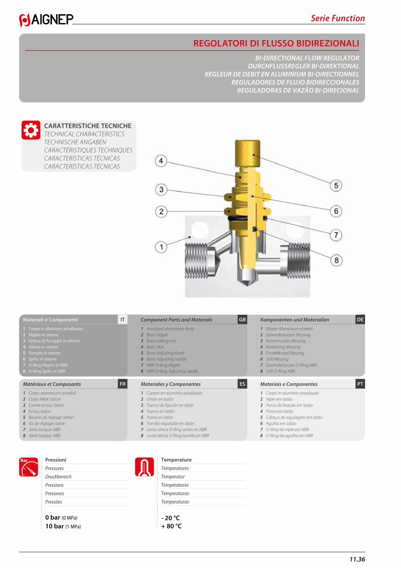
11.36
Serie Function
REGOLATORI DI FLUSSO BIDIREZIONALIBI-DIRECTIONAL FLOW REGULATOR
DURCHFLUSSREGLER BI-DIREKTIONALREGLEUR DE DEBIT EN ALUMINIUM BI-DIRECTIONNEL
REGULADORES DE FLUJO BIDIRECCIONALESREGULADORAS DE VAZÃO BI-DIRECIONAL
CARATTERISTICHE TECNICHE TECHNICAL CHARACTERISTICS TECHNISCHE ANGABEN CARACTÉRISTIQUES TECHNIQUES CARACTERÍSTICAS TÉCNICAS CARACTERÍSTICAS TÉCNICAS
PTESFR
DEGBITMateriali e Componenti
1 Corpo in alluminio anodizzato 2 Nipplo in ottone 3 Ghiera di fissaggio in ottone 4 Ghiera in ottone 5 Pomolo in ottone6 Spillo in ottone7 O-Ring Nipplo in NBR8 O-Ring Spillo in NBR
Matériaux et Composants
1 Corps: aluminium anodisé2 Corps fileté: laiton3 Contre écrou: laiton4 Ecrou: laiton5 Bouton de réglage: laiton6 Vis de réglage: laiton7 Joint torique: NBR 8 Joint torique: NBR
Component Parts and Materials
1 Anodized aluminium Body2 Brass Nipple3 Brass Loking nut4 Brass Nut5 Brass Adjusting Knob6 Brass Adjusting needle7 NBR O-Ring Nipple8 NBR O-Ring Adjusting needle
Materiales y Componentes
1 Cuerpo en aluminio anodizado2 Unión en latón3 Tuerca de fijación en latón4 Tuerca en latón5 Pomo en latón6 Tornillo regulador en latón7 Junta tórica O-Ring unión en NBR8 Junta tórica O-Ring tornillo en NBR
Komponenten und Materialien
1 Körper Aluminium eloxiert2 Gewindestutzen Messing3 Kontermutter Messing4 Konterring Messing5 Einstellknopf Messing6 Stift Messing7 Gewindestutzen O-Ring NBR 8 Stift O-Ring NBR
Materiais e Componentes
1 Corpo in alumínio anodizado2 Niple em latão3 Porca de fixação em latão4 Porca em latão5 Cabeça de regulagem em latão6 Agulha em latão7 O-Ring do niple em NBR 8 O-Ring da agulha em NBR
0 bar (0 MPa)
10 bar (1 MPa)
Pressioni
Pressures
Druckbereich
Pressions
Presiones
Pressões
Bar
- 20 °C+ 80 °C
Temperature
Temperatures
Temperatur
Températures
Temperaturas
Temperaturas
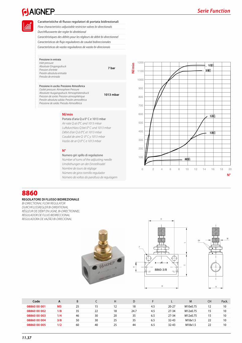
Serie Function
11.37
8860REGOLATORE Dl FLUSSO BIDIREZIONALE Bl-DIRECTIONAL FLOW REGULATOR DURCHFLUSSREGLER BI-DIREKTIONAL RÉGLEUR DE DÉBIT EN LIGNE, BI-DIRECTIONNEL REGULADOR DE FLUJO BIDIRECCIONAL REGULADORA DE VAZÃO BI-DIRECIONAL D
F
B H
CH
L
A
C
M
8860-3/8
Code A B C H D F L M CH Pack.
08860 00 001 M5 25 15 12 18 4.5 20-27 M10x0.75 12 1008860 00 002 1/8 35 22 18 24.7 4.5 27-34 M12x0.75 15 10
08860 00 003 1/4 46 30 20 35 6.5 27-34 M12x0.75 15 10
08860 00 004 3/8 50 30 25 35 6.5 32-43 M18x1.5 22 10
08860 00 005 1/2 60 40 25 44 6.5 32-43 M18x1.5 22 10
Caratteristiche di flusso regolatori di portata bidirezionali
Flow characteristics adjustable restrictor valves bi-directionals
Durchflusswerte der regler bi-direktional
Caractéristiques des débits pour les régleurs de débit bi-directionnel
Características de flujo reguladores de caudal bidireccionales
Características de vazão reguladoras de vazão bi-direcionais
0
1100
100
1000
200
900
300
800
400
700
500
600
10 12 14 16 18 20
1200
M5
2 4 6 8
1/2
3/8
1/4
1/8
Pressione in entrata Inlet pressureAbsoluter EingangsdruckPression d’entréePresión absoluta entradaPressão de entrada
7 bar
Pressione in uscita: Pressione AtmosfericaOutlet pressure: Atmosphere PressureAbsoluter Ausgangsdruck: AtmosphärendruckPression de sortie: Pression atmosphériquePresión absoluta salida: Presión atmosféricaPressione de saída: Pressão Atmosférica
1013 mbar
Nl/minPortata d’aria Q a 0° C e 1013 mbar Air rate Q at 0°C and 1013 mbarLuftdurchlass Q bei 0° C und 1013 mbarDébit d’air Q à 0°C et 1013 mbarCaudal de aire Q 0° C y 1013 mbarVazão de ar Q 0° C e 1013 mbar
N°Numero giri spillo di regolazioneNumber of turns of the adjiusting needleUmdrehungen an der EinstellnadelNombre de tours de réglageNúmero de giros tornillo reguladorNúmero de voltas do parafuso de regulagem
Nl/m
in
N°
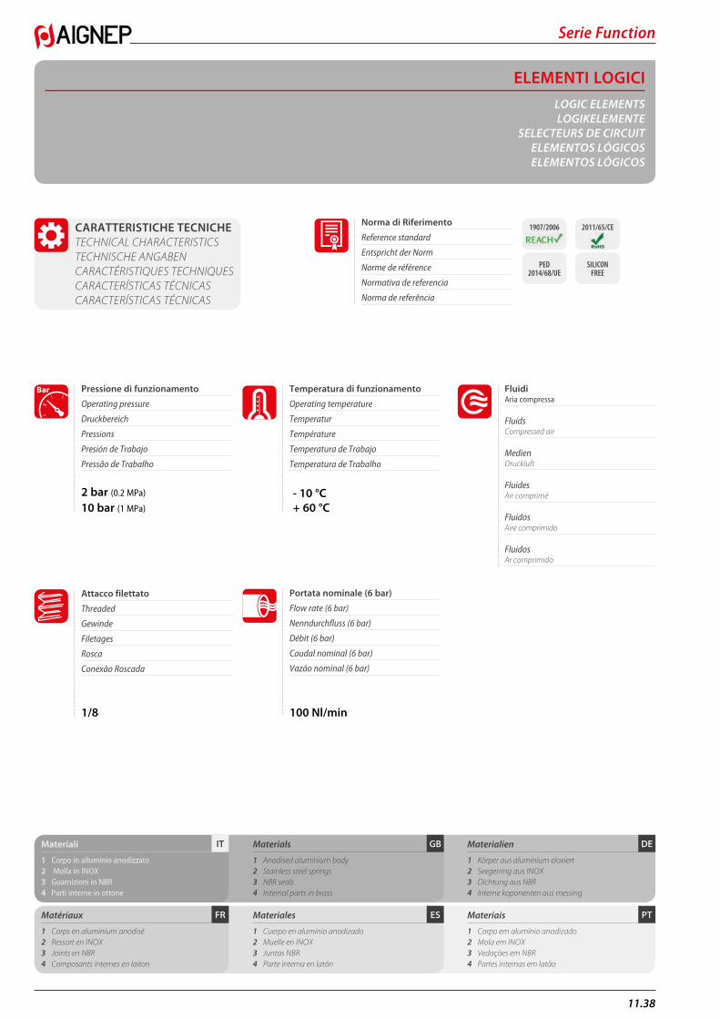
11.38
Serie Function
ELEMENTI LOGICILOGIC ELEMENTSLOGIKELEMENTE
SELECTEURS DE CIRCUITELEMENTOS LÓGICOS ELEMENTOS LÓGICOS
CARATTERISTICHE TECNICHE TECHNICAL CHARACTERISTICS TECHNISCHE ANGABEN CARACTÉRISTIQUES TECHNIQUES CARACTERÍSTICAS TÉCNICAS CARACTERÍSTICAS TÉCNICAS
PTESFR
DEGBITMateriali
1 Corpo in alluminio anodizzato2 Molla in INOX3 Guarnizioni in NBR4 Parti interne in ottone
Matériaux
1 Corps en aluminium anodisé2 Ressort en INOX3 Joints en NBR4 Composants internes en laiton
Materials
1 Anodised aluminium body2 Stainless steel springs3 NBR seals4 Internal parts in brass
Materiales
1 Cuerpo en aluminio anodizado 2 Muelle en INOX 3 Juntas NBR 4 Parte interna en latón
Materialien
1 Körper aus aluminium eloxiert2 Seegerring aus INOX3 Dichtung aus NBR4 Interne koponenten aus messing
Materiais
1 Corpo em alumínio anodizado 2 Mola em INOX 3 Vedações em NBR 4 Partes internas em latão
2 bar (0.2 MPa)
10 bar (1 MPa)
- 10 °C+ 60 °C
Fluidi Aria compressa
Fluids Compressed air
Medien Druckluft
Fluides Air comprimé
Fluidos Aire comprimido
Fluidos Ar comprimido
Pressione di funzionamento
Operating pressure
Druckbereich
Pressions
Presión de Trabajo
Pressão de Trabalho
Temperatura di funzionamento
Operating temperature
Temperatur
Température
Temperatura de Trabajo
Temperatura de Trabalho
Bar
1/8 100 Nl/min
Attacco filettato
Threaded
Gewinde
Filetages
Rosca
Conexão Roscada
Norma di Riferimento
Reference standard
Entspricht der Norm
Norme de référence
Normativa de referencia
Norma de referência
1907/2006 2011/65/CE
PED 2014/68/UE
SILICON FREE
Portata nominale (6 bar)
Flow rate (6 bar)
Nenndurchfluss (6 bar)
Débit (6 bar)
Caudal nominal (6 bar)
Vazão nominal (6 bar)
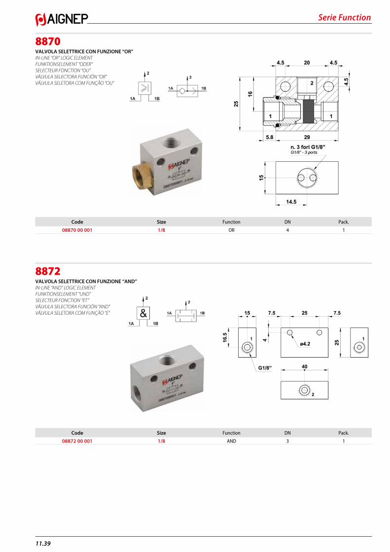
Serie Function
11.39
8870VALVOLA SELETTRICE CON FUNZIONE “OR” IN-LINE “OR” LOGIC ELEMENT FUNKTIONSELEMENT “ODER” SELECTEUR FONCTION “OU” VÁLVULA SELECTORA FUNCIÓN “OR” VÁLVULA SELETORA COM FUNÇÃO “OU”
8872VALVOLA SELETTRICE CON FUNZIONE “AND” IN-LINE “AND” LOGIC ELEMENT FUNKTIONSELEMENT “UND” SELECTEUR FONCTION “ET” VÁLVULA SELECTORA FUNCIÓN “AND” VÁLVULA SELETORA COM FUNÇÃO “E”
Code Size Function DN Pack.
08870 00 001 1/8 OR 4 1
Code Size Function DN Pack.
08872 00 001 1/8 AND 3 1
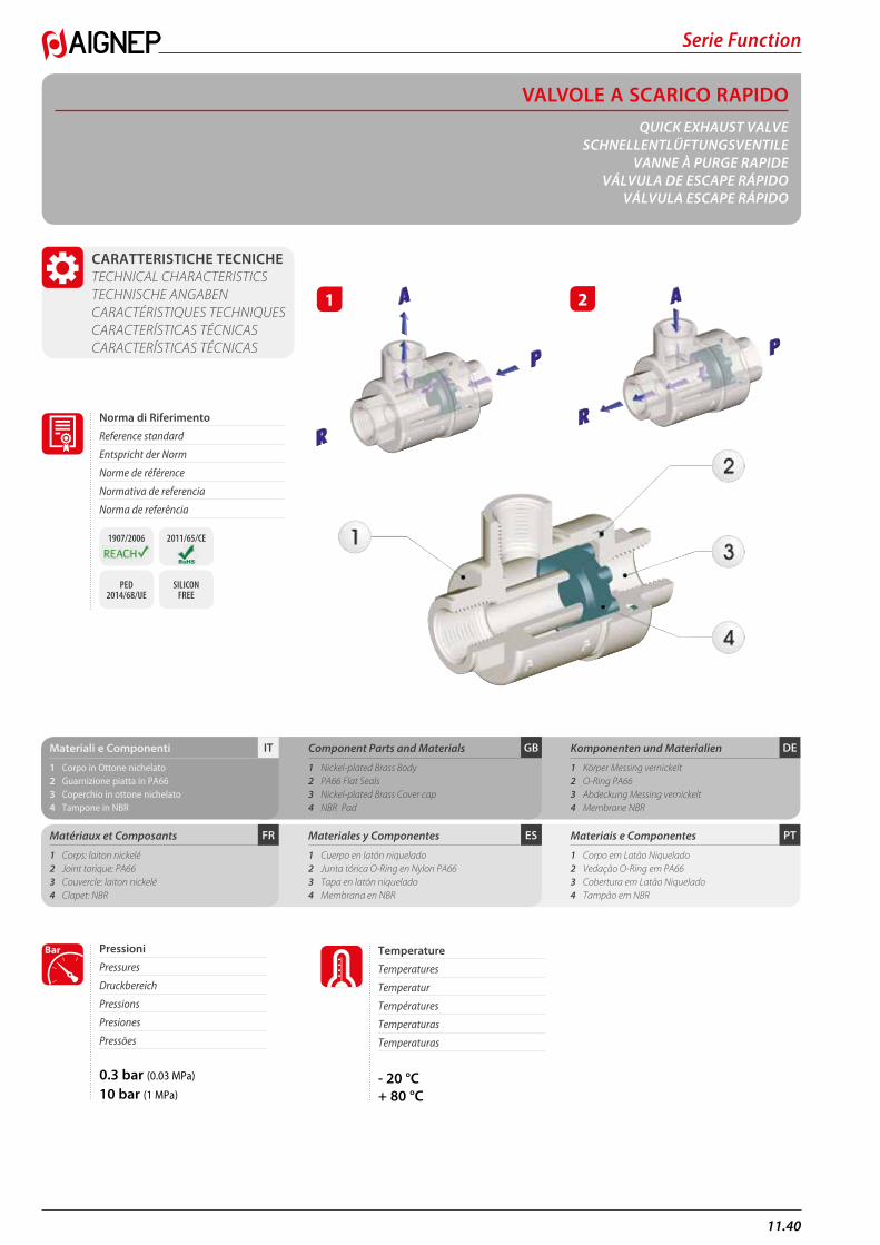
11.40
Serie Function
VALVOLE A SCARICO RAPIDOQUICK EXHAUST VALVE
SCHNELLENTLÜFTUNGSVENTILEVANNE À PURGE RAPIDE
VÁLVULA DE ESCAPE RÁPIDOVÁLVULA ESCAPE RÁPIDO
CARATTERISTICHE TECNICHE TECHNICAL CHARACTERISTICS TECHNISCHE ANGABEN CARACTÉRISTIQUES TECHNIQUES CARACTERÍSTICAS TÉCNICAS CARACTERÍSTICAS TÉCNICAS
PTESFR
DEGBITMateriali e Componenti
1 Corpo in Ottone nichelato2 Guarnizione piatta in PA66 3 Coperchio in ottone nichelato4 Tampone in NBR
Matériaux et Composants
1 Corps: laiton nickelé2 Joint torique: PA66 3 Couvercle: laiton nickelé 4 Clapet: NBR
Component Parts and Materials
1 Nickel-plated Brass Body2 PA66 Flat Seals3 Nickel-plated Brass Cover cap 4 NBR Pad
Materiales y Componentes
1 Cuerpo en latón niquelado 2 Junta tórica O-Ring en Nylon PA66 3 Tapa en latón niquelado4 Membrana en NBR
Komponenten und Materialien
1 Körper Messing vernickelt2 O-Ring PA663 Abdeckung Messing vernickelt4 Membrane NBR
Materiais e Componentes
1 Corpo em Latão Niquelado 2 Vedação O-Ring em PA66 3 Cobertura em Latão Niquelado4 Tampão em NBR
0.3 bar (0.03 MPa)
10 bar (1 MPa)
Pressioni
Pressures
Druckbereich
Pressions
Presiones
Pressões
Bar
- 20 °C+ 80 °C
Temperature
Temperatures
Temperatur
Températures
Temperaturas
Temperaturas
1 2
Norma di Riferimento
Reference standard
Entspricht der Norm
Norme de référence
Normativa de referencia
Norma de referência
1907/2006 2011/65/CE
PED 2014/68/UE
SILICON FREE
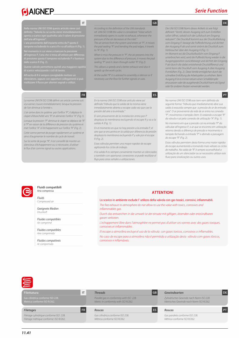
Serie Function
11.41
PTESFR
DEGBIT
Nella norma UNI ISO 5598 questo articolo viene così definito: “Valvola la cui uscita viene immediatamente aperta a scarico ogni qualvolta cala il valore di pressione dell’aria all’ingresso”. L’aria proveniente dall’impianto entra da P sposta il tampone escludendo lo scarico R e va all’utilizzo A (Fig. 1).
Nel momento in cui viene a mancare la pressione all’ingresso P, l’aria che si trova all’utilizzo per differenza di pressione sposta il tampone escludendo P e fuoriesce dallo scarico R (Fig. 2).
Queste valvole permettono quindi una maggiore rapidità di scarico velocizzando i cicli di lavoro.
All’uscita di R é sempre consigliabile mettere un silenziatore, oppure con opportuni collegamenti si può riutilizzare il flusso per ulteriori segnali o utilizzi.
La norme UNI EN ISO 5598 définit cet article comme suit: «La vanne s’ouvre immédiatement, lorsque la pression de l’air diminue à l’entrée ».
L’air arrive dans le système par l’orifice “P”, il déplace le clapet d’étanchéité vers “R” et alimente l’orifice “A” (Fig 1).
Lorsque la pression “P” diminue le clapet se déplace de “R” à “P” en raison de la différence de pression du système et met l’orifice “A” à l’échappement sur l’orifice “R” (Fig. 2).
Cette vanne permet de purger rapidement un système et ainsi d’augmenter le nombre de cycle de travail.
Sur la sortie de purge “R”, il est conseillé de monter un silencieux d’échappement ou si nécessaire, d’utiliser le flux d’air comme signal ou autres applications.
According to the definition of the UNI standards ref. UNI-ISO 5598 this valve is considered: “Valve which immediately opens its outlet to exhaust, whenever the pressure of the air decreases at the inlet.” The air arrives from the system and enters at “P”, it moves the pad sealing “R” and bending the pad edges, it travels to “A” (Fig. 1).
When it miss the pressure in “P”, the air presents into the system due to the difference of pressure, it moves the pad sealing “P” and it clears through outlet “R” (Fig 2).
This allows a speedy and a better exhaust and also it speeds up the work cycles.
At the outlet “R” it is advised to assembly a silencer or if necessary use the flow for further signals or uses.
En la norma UNI ISO 5598 este artículo viene así definido:”Válvula que la salida de la misma viene inmediatamente abierta a escape cada vez que cae la presión del aire a la entrada.”
El aire proveniente de la instalación entra por P desplaza la membrana excluyendo el escape R y va a la salida A (Fig. 1).
En el momento en que no hay presión a la entrada P, el aire que se encuentra en la salida por diferencia de presión desplaza la membrana excluyendo P y sale por el escape R (Fig. 2).
Estas válvulas permiten una mayor rapidez de escape agilizando los ciclos de trabajo.
A la salida R es siempre conveniente montar un silenciador, o también con oportunas conexiones se puede reutilizar el flujo para otras señales o utilizaciones.
Die UNI ISO 5598 Norm dieses Artikels ist wie folgt definiert: “Ventil, dessen Ausgang sich zum Entlüften sofort öffnet, sobald sich der Luftdruck am Eingang reduziert”. Die Druckluft kommt aus der Druckluftleitung vom Eingang P, bewegt die Pufferdichtung und dichtet den Ausgang R ab und somit strömt die Druckluft zum Verbraucher über den Ausgang A (Fig. 1). Im Moment wo die Druckluftzufuhr vom Eingang P unterbrochen wird, wird die Pufferdichtung wieder in die Ausgangsposition zurückbewegt und dichtet den Eingang P ab (durch die dabei entstehende Druckdifferenz) und somit kann die Druckluft vom Ausgang A über Ausgang R entlüften (Fig. 2). Diese Ventile ermöglichen durch die schnellere Entlüftung die Arbeitszyklen zu erhöhen. Beim Ausgang R ist es immer ratsam einen Schalldämpfer einzusetzen oder die ausgehende Druckluft kann als Signal oder für anderen Nutzen verwendet werden.
Na norma UNI ISO 5598 este item vem definido da seguinte forma: “Válvula que imediatamente abre sua saída à exaustão sempre que a pressão do ar de entrada caia”. O ar proveniente da rede de ar entra na conexão “P”, movimenta o tampão (item 3) vedando o escape “R” da vávula e sai pela conexão de utilização “A” (Fig. 1).
No momento em que a pressão cai na entrada “P” da válvulae all’ingresso P, o ar que se encontra em utilização retorna devido a diferença de pressão e movimenta o tampão fechando a entrada “P” e abrindo a passagem do escape “R” (Fig. 2).
Estas válvulas permitem desta forma uma maior rapidez de escape aumentando a tornando mais velozes os ciclos de trabalho. Na saída de “R” é sempre aconselhável a utilização de um silenciador ou se necessário utilizar este fluxo para sinalizações ou outros usos.
DEGBITFilettatura
Gas cilindrica conforme ISO 228.Metrica conforme ISO R/262.
Threads
Parallel gas in conformity with ISO 228.Metric in conformity with ISO R/262.
Gewindearten
Zylindrisches Gewinde nach Norm ISO 228.Metrisches Gewinde nach Norm ISO R/262.
PTESFRFiletages
Filetage cylindrique conforme ISO 228.Filetage métrique conforme: ISO R/262.
Roscas
Gas cilíndrica conforme ISO 228.Métrica conforme ISO R/262.
Roscas
Gas paralela conforme ISO 228.Métrica conforme ISO R/262.
Fluidi compatibili Aria compressa
Fluids Compressed air
Geeignete Medien Druckluft
Fluides compatibles Air comprimé
Fluidos compatibles Aire comprimido
Fluidos compatíveis Ar comprimido
ATTENTION!
Lo scarico in ambiente esclude l’ utilizzo della valvola con gas tossici, corrosivi, infiammabili.
The free exhaust to atmosphere do not allow to use the valve with toxics, corrosives and inflammables gas.
Durch das entweichen in die umwelt ist der einsatz mit giftigen, ätzenden oder entzündbaren gasen verboten.
L’echappement libre dans l’atmosphère ne permet pas d’utiliser ces vannes avec des gazes toxiques, corrosives et inflammables .
El escape a atmosfera excluye el uso de la válvula con gases toxicos, corrosivos o inflamables.
No caso de escape para a atmosfera não é permitida a utilização desta válvula com gases tóxicos, corrosivos e inflamáveis.

11.42
Serie Function
6050VALVOLA A SCARICO RAPIDO QUICK EXHAUST VALVE SCHNELLENTLÜFTUNGSVENTILE VANNE À PURGE RAPIDE VÁLVULA DE ESCAPE RÁPIDO VÁLVULA DE ESCAPE RÁPIDO
6052TAMPONE PER VALVOLA A SCARICO RAPIDO IN NBR PAD FOR QUICK EXHAUST VALVE MADE IN NBR MEMBRANE NBR FÜR SCHNELLENTLÜFTUNGSVENTILE MEMBRANE NBR POUR PURGE RAPIDE MEMBRANA PARA VÁLVULA DE ESCAPE RÁPIDO EN NBR TAMPÃO PARA VÁLVULA DE ESCAPE RÁPIDO EM NBR
6052TAMPONE PER VALVOLA A SCARICO RAPIDO IN POLIURETANO PAD FOR QUICK EXHAUST VALVE MADE IN POLYURETHANE MEMBRANE POLYURETHAN FÜR SCHNELLENTLÜFTUNGSVENTILE MEMBRANE EN POLYURETHANE POUR PURGE RAPIDE MEMBRANA PARA VÁLVULA DE ESCAPE RÁPIDO EN POLIURETANO TAMPÃO PARA VÁLVULA DE ESCAPE RÁPIDO EM POLIURETANO
6053GUARNIZIONE COPERCHIO CAP SEAL ABDECKUNGSDICHTUNG JOINT POUR COUVERCLE JUNTA TAPA VEDAÇÃO DA COBERTURA
Code A B L1 L2 CH Pack.
06050 00 001 M5 4 25 10 17 1006050 00 002 1/8 8.5 42 19.5 15 10
06050 00 003 1/4 11 54 25 19 10
06050 00 004 3/8 12 60.5 26.5 22 10
06050 00 005 1/2 15 72 32 26 10
06050 00 006 3/4 18.5 88 37 32 5
06050 00 007 1” 19 109 48 46 1
L2
L1
A
A
A
B
CH
Code Size Pack.
06052 00 29 B5 00 M5 2006052 00 29 02 00 1/8 20
06052 00 29 03 00 1/4 20
06052 00 29 04 00 3/8 10
06052 00 29 05 00 1/2 10
06052 00 29 07 00 3/4 5
06052 00 29 09 00 1“ 5
min max
Temperature - 20 °C + 80 °C
Code Size Pack.
06052 00 35 02 00 1/8 2006052 00 35 03 00 1/4 20
06052 00 35 05 00 1/2 10
06052 00 35 07 00 3/4 5
min max
Temperature - 30 °C + 100 °C
Code Size D1 D2 S Pack.
06053 00 25 B5 00 M5 15,8 13 1 2006053 00 25 02 00 1/8 24 20.2 1.3 20
06053 00 25 03 00 1/4 29 25.4 1.5 20
06053 00 25 04 00 3/8 33.5 28 1.5 10
06053 00 25 05 00 1/2 38.8 32 1.5 10
06053 00 25 07 00 3/4 43 38 1.5 5
06053 00 25 09 00 1“ 68.5 60.5 3.4 5
S
D2
D1
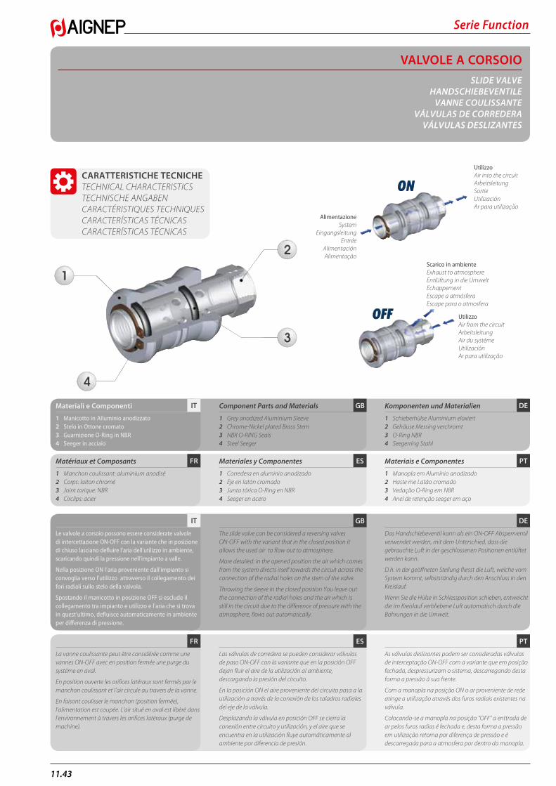
Serie Function
11.43
VALVOLE A CORSOIOSLIDE VALVE
HANDSCHIEBEVENTILEVANNE COULISSANTE
VÁLVULAS DE CORREDERAVÁLVULAS DESLIZANTES
CARATTERISTICHE TECNICHE TECHNICAL CHARACTERISTICS TECHNISCHE ANGABEN CARACTÉRISTIQUES TECHNIQUES CARACTERÍSTICAS TÉCNICAS CARACTERÍSTICAS TÉCNICAS
AlimentazioneSystem
EingangsleitungEntrée
AlimentaciónAlimentação
UtilizzoAir into the circuitArbeitsleitungSortieUtilizaciónAr para utilização
Scarico in ambienteExhaust to atmosphereEntlüftung in die UmweltEchappementEscape a atmósferaEscape para o atmosfera
UtilizzoAir from the circuitArbeitsleitungAir du systèmeUtilizaciónAr para utilização
PTESFR
DEGBITMateriali e Componenti
1 Manicotto in Alluminio anodizzato 2 Stelo in Ottone cromato3 Guarnizione O-Ring in NBR 4 Seeger in acciaio
Matériaux et Composants
1 Manchon coulissant: aluminium anodisé2 Corps: laiton chromé3 Joint torique: NBR 4 Circlips: acier
Component Parts and Materials
1 Grey anodized Aluminium Sleeve2 Chrome-Nickel plated Brass Stem3 NBR O-RING Seals4 Steel Seeger
Materiales y Componentes
1 Corredera en aluminio anodizado 2 Eje en latón cromado 3 Junta tórica O-Ring en NBR 4 Seeger en acero
Komponenten und Materialien
1 Schieberhülse Aluminium eloxiert2 Gehäuse Messing verchromt3 O-Ring NBR 4 Seegerring Stahl
Materiais e Componentes
1 Manopla em Alumínio anodizado 2 Haste me Latão cromado 3 Vedação O-Ring em NBR4 Anel de retenção seeger em aço
PTESFR
DEGBIT
Le valvole a corsoio possono essere considerate valvole di intercettazione ON-OFF con la variante che in posizione di chiuso lasciano defluire l’aria dell’utilizzo in ambiente, scaricando quindi la pressione nell’impianto a valle.
Nella posizione ON l’aria proveniente dall’impianto si convoglia verso l’utilizzo attraverso il collegamento dei fori radiali sullo stelo della valvola.
Spostando il manicotto in posizione OFF si esclude il collegamento tra impianto e utilizzo e l’aria che si trova in quest’ultimo, defluisce automaticamente in ambiente per differenza di pressione.
La vanne coulissante peut être considérée comme une vannes ON-OFF avec en position fermée une purge du systéme en aval.
En position ouverte les orifices latéraux sont fermés par le manchon coulissant et l’air circule au travers de la vanne.
En faisont coulisser le manchon (position fermée), l’alimentation est coupée. L’air situé en aval est libèrè dans l’environnement à travers les orifices latéraux (purge de machine).
The slide valve can be considered a reversing valves ON-OFF with the variant that in the closed position it allows the used air to flow out to atmosphere.
More detailed: in the opened position the air which comes from the system directs itself towards the circuit across the connection of the radial holes on the stem of the valve.
Throwing the sleeve in the closed position You leave out the connection of the radial holes and the air which is still in the circuit due to the difference of pressure with the atmosphere, flows out automatically.
Las válvulas de corredera se pueden considerar válvulas de paso ON-OFF con la variante que en la posición OFF dejan fluir el aire de la utilización al ambiente, descargando la presión del circuito.
En la posición ON el aire proveniente del circuito pasa a la utilización a través de la conexión de los taladros radiales del eje de la válvula.
Desplazando la válvula en posición OFF se cierra la conexión entre circuito y utilización, y el aire que se encuentra en la utilización fluye automáticamente al ambiente por diferencia de presión.
Das Handschiebeventil kann als ein ON-OFF Absperrventil verwendet werden, mit dem Unterschied, dass die gebrauchte Luft in der geschlossenen Positionen entlüftet werden kann.
D.h. in der geöffneten Stellung fliesst die Luft, welche vom System kommt, selbstständig durch den Anschluss in den Kreislauf.
Wenn Sie die Hülse in Schliessposition schieben, entweicht die im Kreislauf verbliebene Luft automatisch durch die Bohrungen in die Umwelt.
As válvulas deslizantes podem ser consideradas válvulas de interceptação ON-OFF com a variante que em posição fechada, despressurizam o sistema, descarregando desta forma a pressão à sua frente.
Com a manopla na posição ON o ar proveniente de rede atinge a utilização através dos furos radiais existentes na válvula.
Colocando-se a manopla na posição “OFF” a enttrada de ar pelos furas radias é fechada e, desta forma a pressão em utilização retorna por diferença de pressão e é descarregada para a atmosfera por dentro da manopla.
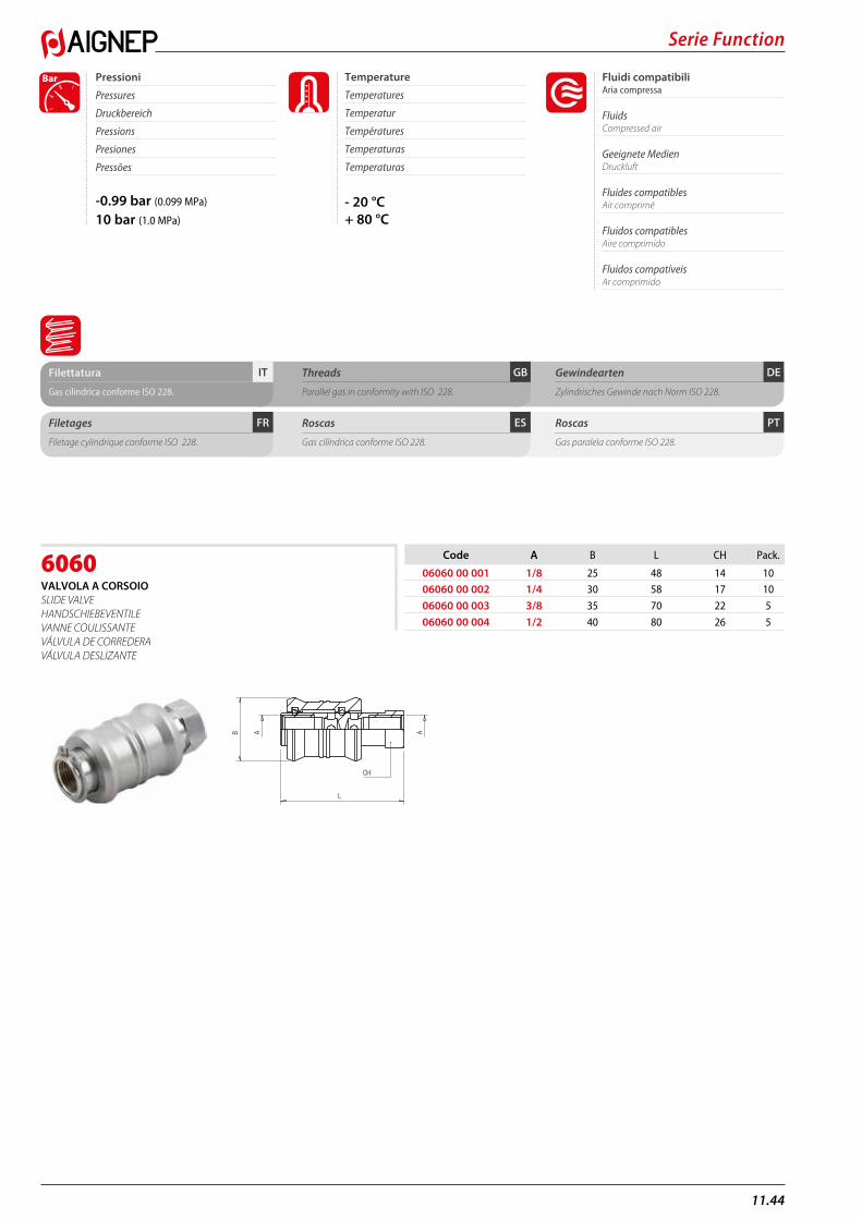
11.44
Serie Function
6060VALVOLA A CORSOIO SLIDE VALVE HANDSCHIEBEVENTILE VANNE COULISSANTE VÁLVULA DE CORREDERA VÁLVULA DESLIZANTE
Code A B L CH Pack.
06060 00 001 1/8 25 48 14 1006060 00 002 1/4 30 58 17 10
06060 00 003 3/8 35 70 22 5
06060 00 004 1/2 40 80 26 5
B
L
A
A
CH
DEGBITFilettatura
Gas cilindrica conforme ISO 228.
Threads
Parallel gas in conformity with ISO 228.
Gewindearten
Zylindrisches Gewinde nach Norm ISO 228.
PTESFRFiletages
Filetage cylindrique conforme ISO 228.
Roscas
Gas cilíndrica conforme ISO 228.
Roscas
Gas paralela conforme ISO 228.
-0.99 bar (0.099 MPa)
10 bar (1.0 MPa)
Fluidi compatibili Aria compressa
Fluids Compressed air
Geeignete Medien Druckluft
Fluides compatibles Air comprimé
Fluidos compatibles Aire comprimido
Fluidos compatíveis Ar comprimido
Pressioni
Pressures
Druckbereich
Pressions
Presiones
Pressões
Bar
- 20 °C+ 80 °C
Temperature
Temperatures
Temperatur
Températures
Temperaturas
Temperaturas
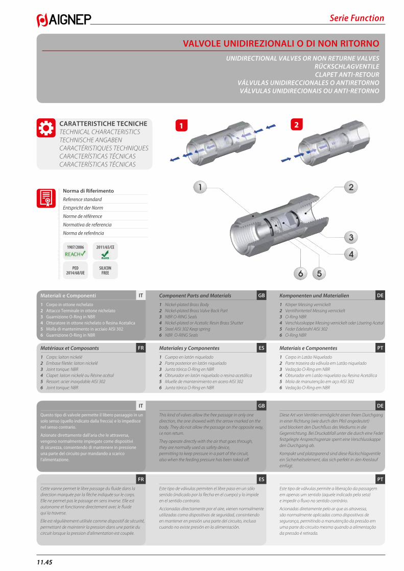
Serie Function
11.45
VALVOLE UNIDIREZIONALI O DI NON RITORNOUNIDIRECTIONAL VALVES OR NON RETURNE VALVES
RÜCKSCHLAGVENTILECLAPET ANTI-RETOUR
VÁLVULAS UNIDIRECCIONALES O ANTIRETORNO VÁLVULAS UNIDIRECIONAIS OU ANTI-RETORNO
CARATTERISTICHE TECNICHE TECHNICAL CHARACTERISTICS TECHNISCHE ANGABEN CARACTÉRISTIQUES TECHNIQUES CARACTERÍSTICAS TÉCNICAS CARACTERÍSTICAS TÉCNICAS
PTESFR
DEGBITMateriali e Componenti
1 Corpo in ottone nichelato2 Attacco Terminale in ottone nichelato3 Guarnizione O-Ring in NBR4 Otturatore in ottone nichelato o Resina Acetalica5 Molla di mantenimento in acciaio AISI 3026 Guarnizione O-Ring in NBR
Matériaux et Composants
1 Corps: laiton nickelé2 Embase filetée: laiton nickelé3 Joint torique: NBR 4 Clapet: laiton nickelé ou Résine acétal5 Ressort: acier inoxydable AISI 3026 Joint torique: NBR
Component Parts and Materials
1 Nickel-plated Brass Body2 Nickel-plated Brass Valve Back Part3 NBR O-RING Seals4 Nickel-plated or Acetalic Resin Brass Shutter5 Steel AISI 302 Keep spring6 NBR O-RING Seals
Materiales y Componentes
1 Cuerpo en latón niquelado2 Parte posterior en latón niquelado3 Junta tórica O-Ring en NBR4 Obturador en latón niquelado o resina acetálica5 Muelle de mantenimiento en acero AISI 3026 Junta tórica O-Ring en NBR
Komponenten und Materialien
1 Körper Messing vernickelt2 Ventilhinterteil Messing vernickelt3 O-Ring NBR 4 Verschlusskappe Messing vernickelt oder Lösering Acetal5 Feder Edelstahl AISI 3026 O-Ring NBR
Materiais e Componentes
1 Corpo in Latão Niquelado 2 Parte traseira da válvula em Latão niquelado 3 Vedação O-Ring em NBR4 Obturador em Latão niquelato ou Resina Acetálica5 Mola de manutenção em aço AISI 3026 Vedação O-Ring em NBR
PTESFR
DEGBIT
Questo tipo di valvole permette il libero passaggio in un solo senso (quello indicato dalla freccia) e lo impedisce nel senso contrario.
Azionate direttamente dall’aria che le attraversa, vengono normalmente impiegate come dispositivi di sicurezza, consentendo di mantenere in pressione una parte del circuito pur mandando a scarico l’alimentazione.
Cette vanne permet le libre passage du fluide dans la direction marquée par la flèche indiquée sur le corps. Elle ne permet pas le passage en sens inverse. Elle est autonome et fonctionne directement avec le fluide qui la traverse.
Elle est régulièrement utilisée comme dispositif de sécurité, permettant de maintenir la pression dans une partie du circuit lorsque la pression d’alimentation est coupée.
This kind of valves allow the free passage in only one direction, the one showed with the arrow marked on the body. They do not allow the passage on the opposite way, i.e non return.
They operate directly with the air that goes through, they are normally used as safety device, permitting to keep pressure in a part of the circuit, also when the feeding pressure has been taked off.
Este tipo de válvulas permiten el libre paso en un sólo sentido (indicado por la flecha en el cuerpo) y lo impide en el sentido contrario.
Accionadas directamente por el aire, vienen normalmente utilizadas como dispositivos de seguridad, consintiendo en mantener en presión una parte del circuito, incluso cuando no existe presión en la alimentación.
Diese Art von Ventilen ermöglicht einen freien Durchgang in einer Richtung (wie durch den Pfeil angedeutet) und blockiert den Durchfluss des Mediums in die Gegenrichtung. Bei Druckabfall unter die durch eine Feder festgelegte Ansprechsgrenze sperrt eine Verschlusskappe den Durchgang ab.
Kompakt und platzsparend sind diese Rückschlagventile ein Sicherheitselement, das sich perfekt in den Kreislauf einfügt.
Este tipo de válvulas permite a liberação da passagem em apenas um sentido (aquele indicado pela seta) e impedir o fluxo no sentido contrário.
Acionadas diretamente pelo ar que as atravessa, são normalmente aplicadas como dispositivos de segurança, permitindo a manutenção da pressão em uma parte do circuito mesmo quando a alimentação da pressão é retirada.
1 2
Norma di Riferimento
Reference standard
Entspricht der Norm
Norme de référence
Normativa de referencia
Norma de referência
1907/2006 2011/65/CE
PED 2014/68/UE
SILICON FREE
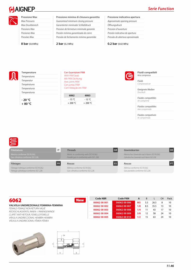
11.46
Serie Function
6062VALVOLA UNIDIREZIONALE FEMMINA-FEMMINA FEMALE-FEMALE NON RETURN VALVE RÜCKSCHLAGVENTIL INNEN- / INNENGEWINDE CLAPET ANTI-RETOUR, FEMELLE/FEMELLE VÁVULA UNIDIRECCIONAL HEMBRA-HEMBRA VÁLVULA UNIDIRECIONAL FÊMEA-FÊMEA
Code NBR Code FKM A B L CH Pack.
06062 00 001 06062 00 006 M5 5.5 26.5 8 1006062 00 002 06062 00 007 1/8 8.5 35.5 13 10
06062 00 003 06062 00 008 1/4 11 43 17 10
06062 00 004 06062 00 009 3/8 12 58 24 10
06062 00 005 06062 00 010 1/2 15 63 24 10
New
B
CH
A A
L
B
PTESFR
DEGBITFilettatura
Metrica conforme ISO R/262.Gas cilindrica conforme ISO 228.
Filetages
Filetage métrique conforme ISO R/262.Filetage cylindrique conforme: ISO 228.
Threads
Metric in conformity with ISO R/262.Parallel gas in conformity with ISO 228.
Roscas
Métrica conforme ISO R/262.Gas cilíndrica conforme ISO 228.
Gewindearten
Metrisches Gewinde nach Norm ISO R/262.Zylindrisches Gewinde nach Norm ISO 228.
Roscas
Métrica conforme ISO R/262.Gas paralela conforme ISO 228.
8 bar (0.8 MPa) 2 bar (0.2 MPa) 0.2 bar (0.02 MPa)
Pressione Max
Max Pressures
Max Druckbereich
Pressions Max
Presiones Max
Pressões Max
Pressione minima di chiusura garantita
Guaranteed minimum closing pressure
Garantierter minimaler Schließdruck
Pression de fermeture minimale garantie
Presión mínima garantizada de cierre
Pressão de fechamento mínima garantida
Pressione indicativa apertura
Approximate opening pressure
Öffnungsdruck
Pression d’ouverture
Presión indicativa de apertura
Pressão de abertura aproximada
Bar
- 20 °C+ 80 °C
Temperature
Temperatures
Temperatur
Températures
Temperaturas
Temperaturas
Fluidi compatibili Aria compressa
Fluids Compressed air
Geeignete Medien Druckluft
Fluides compatibles Air comprimé
Fluidos compatibles Aire comprimido
Fluidos compatíveis Ar comprimido
Con Guarnizioni FKM With FKM Seals Mit FKM Dichtung Avec joints FKM Con juntas FKM Com Vedação em FKM
6062 6063- 15 °C - 15 °C
+ 200 °C + 200 °C
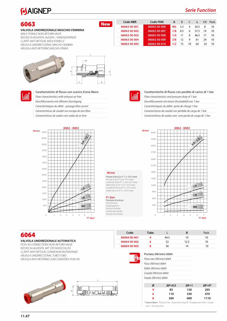
Serie Function
11.47
6063VALVOLA UNIDIREZIONALE MASCHIO-FEMMINA MALE-FEMALE NON-RETURN VALVE RÜCKSCHLAGVENTIL AUSSEN- / INNENGEWINDE CLAPET ANTI-RETOUR, MÂLE/FEMELLE VÁLVULA UNIDIRECCIONAL MACHO-HEMBRA VÁLVULA ANTI-RETORNO MACHO-FÊMEA
6064VALVOLA UNIDIREZIONALE AUTOMATICA PUSH-IN CONNECTIONS NON-RETURN VALVE RÜCKSCHLAGVENTIL MIT STECKANSCHLUSS CLAPET ANTI-RETOUR, CONNEXION INSTANTANEE VÁLVULA UNIDIRECCIONAL TUBO-TUBO VÁLVULA ANTI-RETORNO COM CONEXÕES PUSH-IN
Code NBR Code FKM A B C L CH Pack.
06063 00 001 06063 00 006 M5 5.5 4 34.5 8 1006063 00 002 06063 00 007 1/8 8.5 6 37.5 14 10
06063 00 003 06063 00 008 1/4 11 8 46.5 17 10
06063 00 004 06063 00 009 3/8 12 9 61 24 10
06063 00 005 06063 00 010 1/2 15 10 64 24 10
New
C
A
CH
B
A
L
6062 - 6063 6062 - 6063
Code Tube L B Pack.
06064 00 001 4 44.5 10 1006064 00 002 6 52 12.5 10
06064 00 003 8 56 14 10
Portata (Nl/min) 6064
Flow rate (Nl/min) 6064
Fluss (Nl/min) 6064
Débit (Nl/min) 6064
Caudal (Nl/min) 6064
Vazão (Nl/min) 6064
Ø ΔP=0,5 ΔP=1 ΔP=0*4 85 120 2056 110 330 4708 260 600 1110
* Scarico libero - Exhaust Free - Kostenlose Auspuff - Échappement libre - Escape
Libre - Descarga livre.
L
B
NI/minPortata d’aria Q a 0 ° C e 1013 mbarAir rate Q at 0°C and 1013 mbar Luftstrom Q bei 0 ° C und 1013 mbar Débit d’air Q à 0 ° C et 1 013 mbar Caudal de Aire Q 0° C e 1013 mbar Vazão de ar Q 0° C e 1013 mbar
P1 (bar)Pressione di entrataInlet pressure Eingangsdruck Pression d’entrée Presión de entradaPressão de entrada
Caratteristiche di flusso con perdite di carico di 1 bar
Flow characteristics and pressure drop of 1 bar
Durchflusswerte mit einem Druckabfall von 1 bar
Caractéristiques du débit- perte de charge 1 bar
Características de caudal con pérdida de carga de 1 bar
Caratcerísticas de vazão com com perda de carga de 1 bar
Caratteristiche di flusso con scarico d’aria libero
Flow characteristics with exhaust air free
Durchflusswerte mit offenem Durchgang
Caractéristiques du débit - passage libre ouvert
Características de caudal con escape de aire libre
Caratcerísticas de vazão com saída de ar livre
1 2 3 4 5 6 70
6000
6500
5500
5000
4500
4000
3500
3000
2500
2000
1500
1000
500
3/8 -
1/2
1/4
1/8
M5
0 1 2 3 4 5 6 7
300
600
900
3000
3300
3600
2700
2400
2100
1800
1500
1200
3/8 - 1
/2
1/4
1/8
M5
NI/min NI/min
P1 (bar) P1 (bar)
11.48
Serie Function
57065RACCORDO DIRITTO MASCHIO CILINDRICO CON VALVOLA UNIDREZIONALE NON-RETURN - PUSH-IN - PARALLEL THREAD RÜCKSCHLAVENTILE - DURCHFLUSS VOM STECKANSCHLUSS ZU ZYLINDRISCHEM AUSSENGEWINDE CLAPET ANTI-RETOUR - CONNEXION INSANTANEE - FILETAGE MALE VALVOLA UNIDIRECIONAL - TUBO - ROSCA MACHO VALVULA ANTI-RETORNO - CONEXOES PUSH-IN - ROSCA MACHO
Code Tube A B C D L CH Pack.
57065 00 001 4 M5 3,6 7,5 9,8 13,5 8 1057065 00 002 4 1/8 5,4 13 9,8 40,5 11 10
57065 00 003 6 1/8 5,4 13 12,5 46 12 10
57065 00 004 6 1/4 8 13 12,5 30 12 10
57065 00 005 8 1/8 5,4 13,8 14 47 12 10
57065 00 006 8 1/4 8 16 14 30,5 14 10
57065 00 007 10 1/4 8 16 17 34,5 17 10
57065 00 008 10 3/8 9 20 17 34,5 17 10
57065 00 009 12 3/8 9 20 19,5 39 20 10
57065 00 010 12 1/2 10 25 19,5 44 20 10
New
L
D
A
B
C
CH
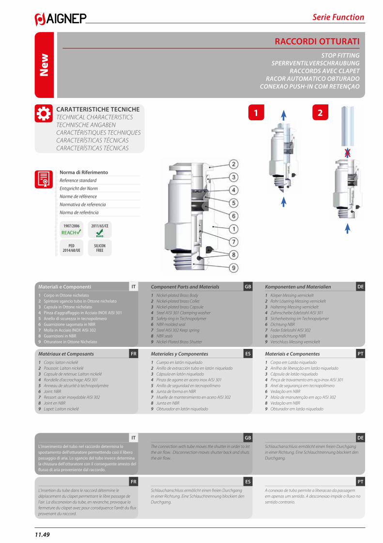
Serie Function
11.49
RACCORDI OTTURATISTOP FITTING
SPERRVENTILVERSCHRAUBUNGRACCORDS AVEC CLAPET
RACOR AUTOMATICO OBTURADOCONEXAO PUSH-IN COM RETENÇAO
CARATTERISTICHE TECNICHE TECHNICAL CHARACTERISTICS TECHNISCHE ANGABEN CARACTÉRISTIQUES TECHNIQUES CARACTERÍSTICAS TÉCNICAS CARACTERÍSTICAS TÉCNICAS
PTESFR
DEGBITMateriali e Componenti
1 Corpo in Ottone nichelato2 Spintore sgancio tubo in Ottone nichelato3 Capsula in Ottone nichelato4 Pinza d'aggraffaggio in Acciaio INOX AISI 3015 Anello di sicurezza in tecnopolimero6 Guarnizione sagomata in NBR7 Molla in Acciaio INOX AISI 3028 Guarnizioni in NBR9 Otturatore in Ottone Nichelato
Matériaux et Composants
1 Corps: laiton nickelé2 Poussoir: Laiton nickelé3 Capsule de retenue: Laiton nickelé4 Rondelle d’accrochage: AISI 3015 Anneau de sécurité à technopolymère6 Joint: NBR7 Ressort: acier inoxydable AISI 3028 Joint en NBR9 Lapet: Laiton nickelé
Component Parts and Materials
1 Nickel-plated Brass Body2 Nickel-plated brass Collet3 Nickel-plated brass Capsule4 Steel AISI 301 Clamping washer5 Safety ring in Technopolymer6 NBR molded seal7 Steel AISI 302 Keep spring8 NBR seals9 Nickel-Plated Brass Shutter
Materiales y Componentes
1 Cuerpo en latón niquelado2 Anillo de extracción tubo en latón niquelado3 Cápsula en latón niquelado4 Pinza de agarre en acero inox AISI 3015 Anillo de seguridad en tecnopolímero6 Junta de forma en NBR7 Muelle de mantenimiento en acero AISI 3028 Junta en NBR9 Obturador en latón niquelado
Komponenten und Materialien
1 Körper Messing vernickelt2 Rohr Lösering Messing vernickelt3 Haltering Messing vernickelt4 Zahnscheibe Edelstahl AISI 3015 Sicherheitsring im Technopolymer6 Dichtung NBR7 Feder Edelstahl AISI 3028 Lippendichtung NBR9 Verschluss Messing vernickelt
Materiais e Componentes
1 Corpo em Latão niquelado 2 Anilha de liberação em latão niquelado3 Cápsula de latão niquelado4 Pinça de travamento em aço-inox AISI 3015 Anel de segurança em tecnopolímero6 Vedação em NBR7 Mola de manutenção em aço AISI 3028 Vedação em NBR9 Obturador em latão niquelado
PTESFR
DEGBIT
L'inserimento del tubo nel raccordo determina lo spostamento dell'otturatore permettendo così il libero passaggio di aria. Lo sgancio del tubo invece determina la chiusura dell'otturatore con il conseguente arresto del flusso di aria proveniente dal raccordo.
L'insertion du tube dans le raccord détermine le déplacement du clapet permettant le libre passage de l'air. La disconexion du tube, en revanche, provoque la fermeture du clapet avec pour conséquence l'arrêt du flux provenant du raccord.
The connection with tube moves the shutter in order to let the air flow. Disconnection moves shutter back and shuts the air flow.
Schlauchanschluss ermölicht einen freien Durchgang in einer Richtung. Eine Schlauchtrennung blockiert den Durchgang.
Schlauchanschluss ermölicht einen freien Durchgang in einer Richtung. Eine Schlauchtrennung blockiert den Durchgang.
A conexao de tubo permite a liberacao da passagem em apenas um sentido. A desconexao impide o fluxo no sentido contrario.
1 2
Norma di Riferimento
Reference standard
Entspricht der Norm
Norme de référence
Normativa de referencia
Norma de referência
1907/2006 2011/65/CE
PED 2014/68/UE
SILICON FREE
X
New
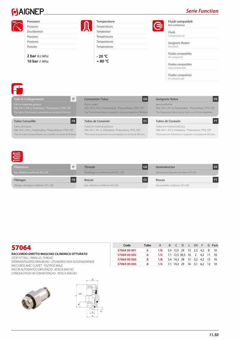
11.50
Serie Function
2 bar (0.2 MPa)
10 bar (1 MPa)
Fluidi compatibili Aria compressa
Fluids Compressed air
Geeignete Medien Druckluft
Fluides compatibles Air comprimé
Fluidos compatibles Aire comprimido
Fluidos compatíveis Ar comprimido
Pressioni
Pressures
Druckbereich
Pressions
Presiones
Pressões
Bar
- 20 °C+ 80 °C
Temperature
Temperatures
Temperatur
Températures
Temperaturas
Temperaturas
PTESFR
DEGBITTubi di Collegamento
Tubi in materiale plastico:PA6, PA11, PA12, Polietilene, *Poliuretano, PTFE, FEP.
*Per tubi in Poliuretano é consigliata una durezza di 98 shore.
Tubes Conseillés
Tubes plastiques:PA6, PA11, PA12, Polyéthylène, *Polyuréthane, PTFE, FEP.
*Pour les tubes en polyuréthane, il est conseillé une dureté de 98 Shore.
Connection Tubes
Plastic tubes:PA6, PA11, PA12, Polyethylene, *Polyurethane, PTFE, FEP.
*For Polyurethane hoses it is required a minimum hardness of 98 shore.
Tubos de Conexión
Tubos en material plástico:PA6, PA11, PA 12, Polietileno, *Poliuretano, PTFE, FEP.
*Para tubos en poliuretano es aconsejada una dureza de 98 shore.
Geeignete Rohre
Kunststoffrohre:PA6, PA11, PA 12, Polyethylene, *Polyurethan, PTFE, FEP.
*Für Polyurethan Rohre ist eine Härte von 98 Shore empfohlen.
Tubos de Conexão
Tubos em material plástico:PA6, PA11, PA12, Polietileno, *Poliuretano, PTFE, FEP.
*Para tubos em Poliuretano é requerida uma dureza de 98 shore.
PTESFR
DEGBITFilettatura
Gas cilindrica conforme ISO 228.
Filetages
Filetage cylindrique conforme: ISO 228.
Threads
Parallel gas in conformity with ISO 228.
Roscas
Gas cilíndrica conforme ISO 228.
Gewindearten
Zylindrisches Gewinde nach Norm ISO 228.
Roscas
Gas paralela conforme ISO 228.
57064RACCORDO DIRITTO MASCHIO CILINDRICO OTTURATO STOP FITTING - PARALLEL THREADSPERRVENTILVERSCHRAUBUNG - ZYLINDRISCHEM AUSSENGEWINDERACCORDS AVEC CLAPET - FILETAGE MALERACOR AUTOMATICO OBTURADO - ROSCA MACHOCONEXAO PUSH-IN COM RETENÇAO - ROSCA MACHO
Code Tube A B C D L CH F G Pack.
57064 00 001 6 1/8 5,4 12,5 29 13 2,3 4,2 8 1057064 00 002 6 1/4 7,1 12,5 30,5 16 2 4,2 11 10
57064 00 003 8 1/8 5,4 14,3 28 15 3,2 4,2 12 10
57064 00 004 8 1/4 7,1 14,3 29 16 3,1 6,2 12 10
G
A
F
D
LB
CH
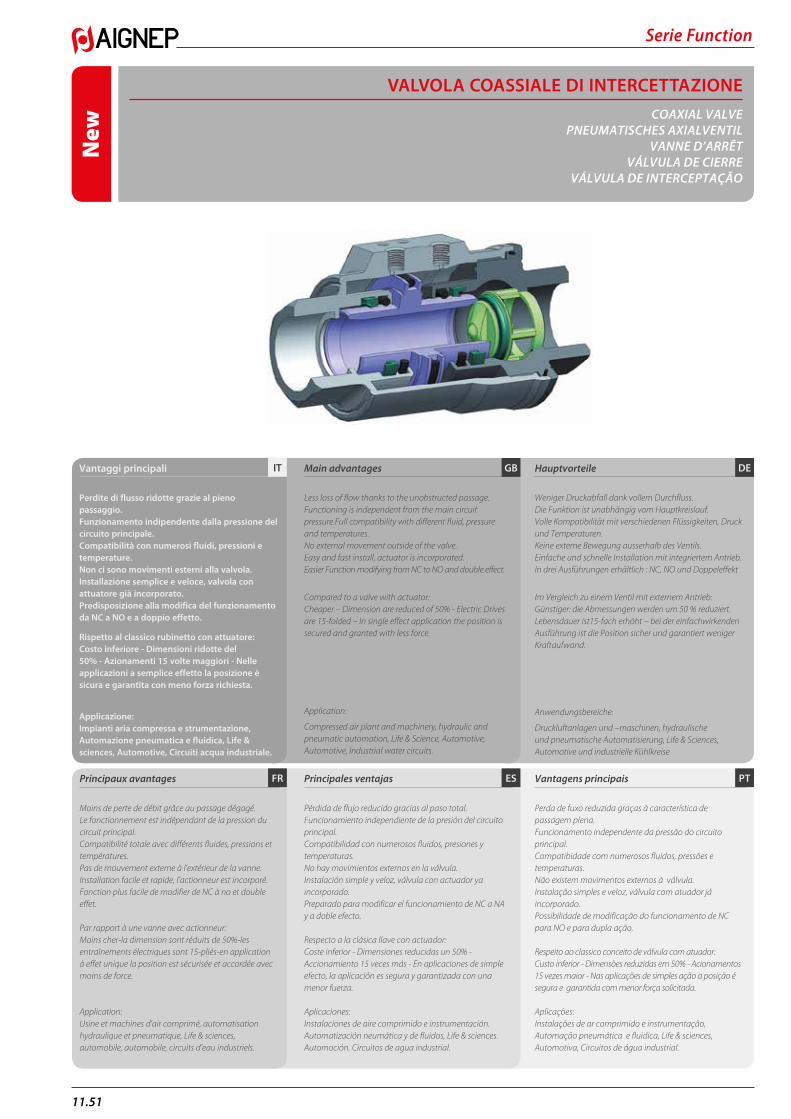
Serie Function
11.51
PTESFR
DEGB
Principaux avantages
Moins de perte de débit grâce au passage dégagé. Le fonctionnement est indépendant de la pression du circuit principal. Compatibilité totale avec différents fluides, pressions et températures. Pas de mouvement externe à l’extérieur de la vanne. Installation facile et rapide, l’actionneur est incorporé. Fonction plus facile de modifier de NC à no et double effet. Par rapport à une vanne avec actionneur: Moins cher-la dimension sont réduits de 50%-les entraînements électriques sont 15-pliés-en application à effet unique la position est sécurisée et accordée avec moins de force.
Application:Usine et machines d’air comprimé, automatisation hydraulique et pneumatique, Life & sciences, automobile, automobile, circuits d’eau industriels.
Main advantages
Less loss of flow thanks to the unobstructed passage. Functioning is independent from the main circuit pressure.Full compatibility with different fluid, pressure and temperatures. No external movement outside of the valve. Easy and fast install, actuator is incorporated. Easier Function modifying from NC to NO and double effect.
Compared to a valve with actuator: Cheaper – Dimension are reduced of 50% - Electric Drives are 15-folded – In single effect application the position is secured and granted with less force.
Application:
Compressed air plant and machinery, hydraulic and pneumatic automation, Life & Science, Automotive, Automotive, Industrial water circuits.
Principales ventajas
Pérdida de flujo reducido gracias al paso total.Funcionamiento independiente de la presión del circuito principal.Compatibilidad con numerosos fluidos, presiones y temperaturas.No hay movimientos externos en la válvula.Instalación simple y veloz, válvula con actuador ya incorporado.Preparado para modificar el funcionamiento de NC a NA y a doble efecto.
Respecto a la clásica llave con actuador:Coste inferior - Dimensiones reducidas un 50% - Accionamiento 15 veces más - En aplicaciones de simple efecto, la aplicación es segura y garantizada con una menor fuerza.
Aplicaciones:Instalaciones de aire comprimido e instrumentación. Automatización neumática y de fluidos, Life & sciences. Automoción. Circuitos de agua industrial.
Hauptvorteile
Weniger Druckabfall dank vollem Durchfluss. Die Funktion ist unabhängig vom Hauptkreislauf. Volle Kompatibilität mit verschiedenen Flüssigkeiten, Druck und Temperaturen. Keine externe Bewegung ausserhalb des Ventils. Einfache und schnelle Installation mit integriertem Antrieb. In drei Ausführungen erhältlich : NC, NO und Doppeleffekt
Im Vergleich zu einem Ventil mit externem Antrieb: Günstiger: die Abmessungen werden um 50 % reduziert. Lebensdauer ist15-fach erhöht – bei der einfachwirkenden Ausführung ist die Position sicher und garantiert weniger Kraftaufwand.
Anwendungsbereiche:
Druckluftanlagen und –maschinen, hydraulische und pneumatische Automatisierung, Life & Sciences, Automotive und industrielle Kühlkreise
Vantagens principais
Perda de fuxo reduzida graças à característica de passagem plena.Funcionamento independente da pressão do circuito principal.Compatibidade com numerosos fluidos, pressões e temperaturas.Não existem movimentos externos à válvula.Instalação simples e veloz, válvula com atuador já incorporado.Possibilidade de modificação do funcionamento de NC para NO e para dupla ação.
Respeito ao classico conceito de válvula com atuador:Custo inferior - Dimensões reduzidas em 50% - Acionamentos 15 vezes maior - Nas aplicações de simples ação a posição é segura e garantida com menor força solicitada.
Aplicações:Instalações de ar comprimido e instrumentação, Automação pneumática e fluidica, Life & sciences, Automotiva, Circuitos de água industrial.
ITVantaggi principali
Perdite di flusso ridotte grazie al pieno passaggio. Funzionamento indipendente dalla pressione del circuito principale. Compatibilità con numerosi fluidi, pressioni e temperature. Non ci sono movimenti esterni alla valvola. Installazione semplice e veloce, valvola con attuatore già incorporato. Predisposizione alla modifica del funzionamento da NC a NO e a doppio effetto.
Rispetto al classico rubinetto con attuatore: Costo inferiore - Dimensioni ridotte del 50% - Azionamenti 15 volte maggiori - Nelle applicazioni a semplice effetto la posizione è sicura e garantita con meno forza richiesta.
Applicazione: Impianti aria compressa e strumentazione, Automazione pneumatica e fluidica, Life & sciences, Automotive, Circuiti acqua industriale.
VALVOLA COASSIALE DI INTERCETTAZIONECOAXIAL VALVE
PNEUMATISCHES AXIALVENTILVANNE D’ARRÊT
VÁLVULA DE CIERREVÁLVULA DE INTERCEPTAÇÃO
New
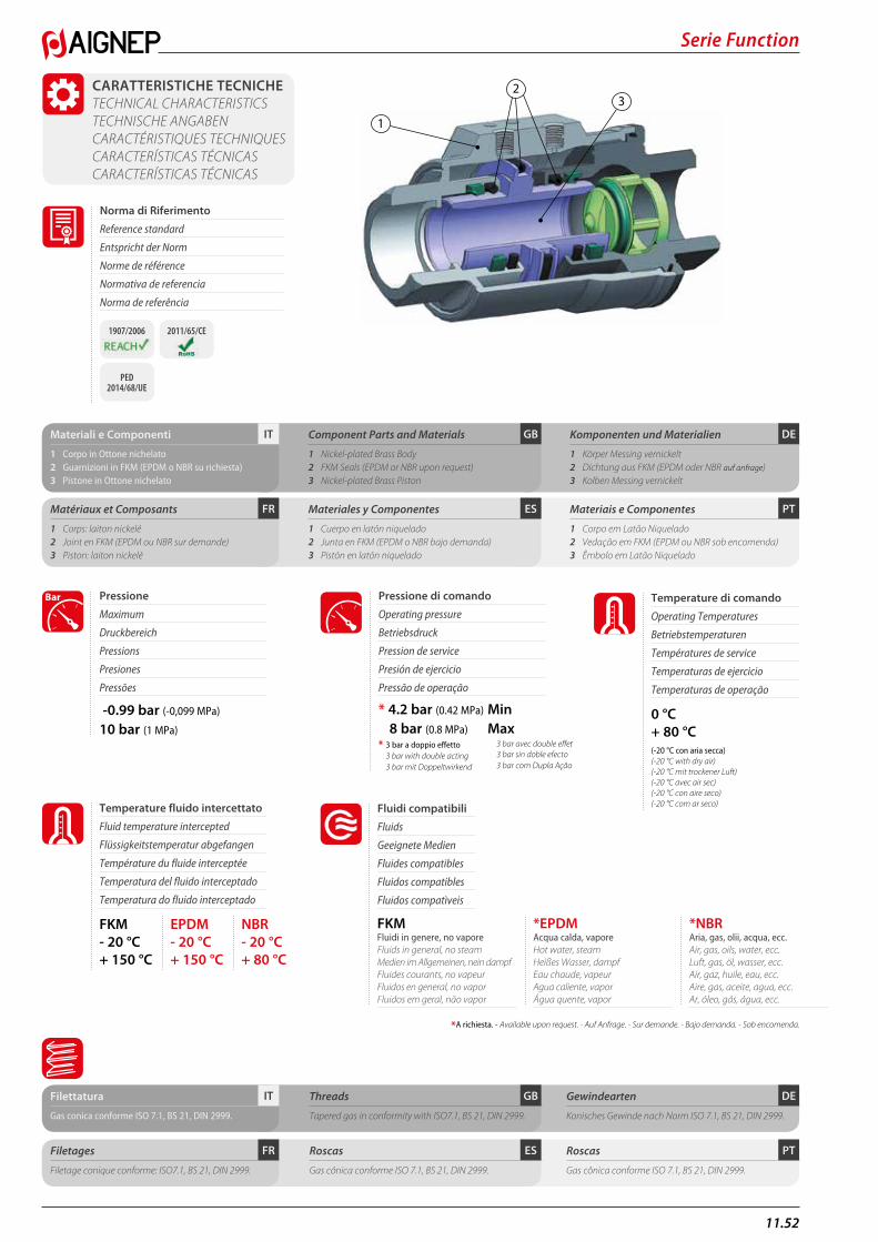
11.52
Serie Function
CARATTERISTICHE TECNICHE TECHNICAL CHARACTERISTICS TECHNISCHE ANGABEN CARACTÉRISTIQUES TECHNIQUES CARACTERÍSTICAS TÉCNICAS CARACTERÍSTICAS TÉCNICAS
PTESFR
DEGBITMateriali e Componenti
1 Corpo in Ottone nichelato2 Guarnizioni in FKM (EPDM o NBR su richiesta)3 Pistone in Ottone nichelato
Matériaux et Composants
1 Corps: laiton nickelé2 Joint en FKM (EPDM ou NBR sur demande)3 Piston: laiton nickelé
Component Parts and Materials
1 Nickel-plated Brass Body2 FKM Seals (EPDM or NBR upon request)3 Nickel-plated Brass Piston
Materiales y Componentes
1 Cuerpo en latón niquelado 2 Junta en FKM (EPDM o NBR bajo demanda)3 Pistón en latón niquelado
Komponenten und Materialien
1 Körper Messing vernickelt2 Dichtung aus FKM (EPDM oder NBR auf anfrage)3 Kolben Messing vernickelt
Materiais e Componentes
1 Corpo em Latão Niquelado 2 Vedação em FKM (EPDM ou NBR sob encomenda)3 Êmbolo em Latão Niquelado
Norma di Riferimento
Reference standard
Entspricht der Norm
Norme de référence
Normativa de referencia
Norma de referência
1907/2006 2011/65/CE
PED 2014/68/UE
1
32
DEGBITFilettatura
Gas conica conforme ISO 7.1, BS 21, DIN 2999.
Threads
Tapered gas in conformity with ISO7.1, BS 21, DIN 2999.
Gewindearten
Konisches Gewinde nach Norm ISO 7.1, BS 21, DIN 2999.
PTESFRFiletages
Filetage conique conforme: ISO7.1, BS 21, DIN 2999.
Roscas
Gas cónica conforme ISO 7.1, BS 21, DIN 2999.
Roscas
Gas cônica conforme ISO 7.1, BS 21, DIN 2999.
Pressione
Maximum
Druckbereich
Pressions
Presiones
Pressões
Bar
FKM - 20 °C+ 150 °C
EPDM - 20 °C+ 150 °C
NBR - 20 °C+ 80 °C
Temperature fluido intercettato
Fluid temperature intercepted
Flüssigkeitstemperatur abgefangen
Température du fluide interceptée
Temperatura del fluido interceptado
Temperatura do fluido interceptado
* 4.2 bar (0.42 MPa) Min
8 bar (0.8 MPa) Max -0.99 bar (-0,099 MPa)
10 bar (1 MPa)
Pressione di comando
Operating pressure
Betriebsdruck
Pression de service
Presión de ejercicio
Pressão de operação
* 3 bar a doppio effetto 3 bar with double acting 3 bar mit Doppeltwirkend
3 bar avec double effet 3 bar sin doble efecto 3 bar com Dupla Ação
A richiesta. - Available upon request. - Auf Anfrage. - Sur demande. - Bajo demanda. - Sob encomenda.*
Fluidi compatibili
Fluids
Geeignete Medien
Fluides compatibles
Fluidos compatibles
Fluidos compatìveis
FKMFluidi in genere, no vapore Fluids in general, no steam Medien im Allgemeinen, nein dampf Fluides courants, no vapeur Fluidos en general, no vapor Fluidos em geral, não vapor
*EPDMAcqua calda, vapore Hot water, steam Heißes Wasser, dampf Eau chaude, vapeur Agua caliente, vapor Água quente, vapor
*NBRAria, gas, olii, acqua, ecc. Air, gas, oils, water, ecc. Luft, gas, öl, wasser, ecc. Air, gaz, huile, eau, ecc. Aire, gas, aceite, agua, ecc. Ar, óleo, gás, água, ecc.
0 °C+ 80 °C
Temperature di comando
Operating Temperatures
Betriebstemperaturen
Températures de service
Temperaturas de ejercicio
Temperaturas de operação
(-20 °C con aria secca) (-20 °C with dry air) (-20 °C mit trockener Luft) (-20 °C avec air sec) (-20 °C con aire seco) (-20 °C com ar seco)
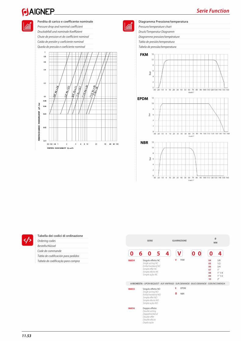
Serie Function
11.53
Diagramma Pressione/temperatura
Pressure/temperature chart
Druck/Temperatur Diagramm
Diagramme pression/température
Tabla de presión/temperatura
Tabela de pressão/temperatura
Perdita di carico e coefficente nominale
Pressure drop and nominal coefficient
Druckabfall und nominale Koeffizient
Chute de pression et de coefficient nominal
Caída de presión y coeficiente nominal
Queda de pressão e coeficiente nominal
NBR
EPDM
FKM
Tabella dei codici di ordinazione
Ordering codes
Bestellschlüssel
Code de commande
Tabla de codificación para pedidos
Tabela de codificação para compra
SERIE GUARNIZIONE
A RICHIESTA - UPON REQUEST - AUF ANFRAGE - SUR DEMANDE - BAJO DEMANDE - SOB ENCOMENDA
Ø
MM
4004 3/805 1/206 3/407 1”08 1” 1/409 1” 1/210 2”
5 40006054 Singolo effetto NC Single acting NC Einfachwirkend NC Simple effet NC Simple efecto NC Simple ação NC
VV FKM
0 0
E EPDM
0 NBR
06055 Singolo effetto NO Single acting NO Einfachwirkend NO Simple effet NO Simple efecto NO Simple ação NO
06056 Doppio effetto Double acting Doppeltwirkend Double effet Double efecto Dupla ação
6
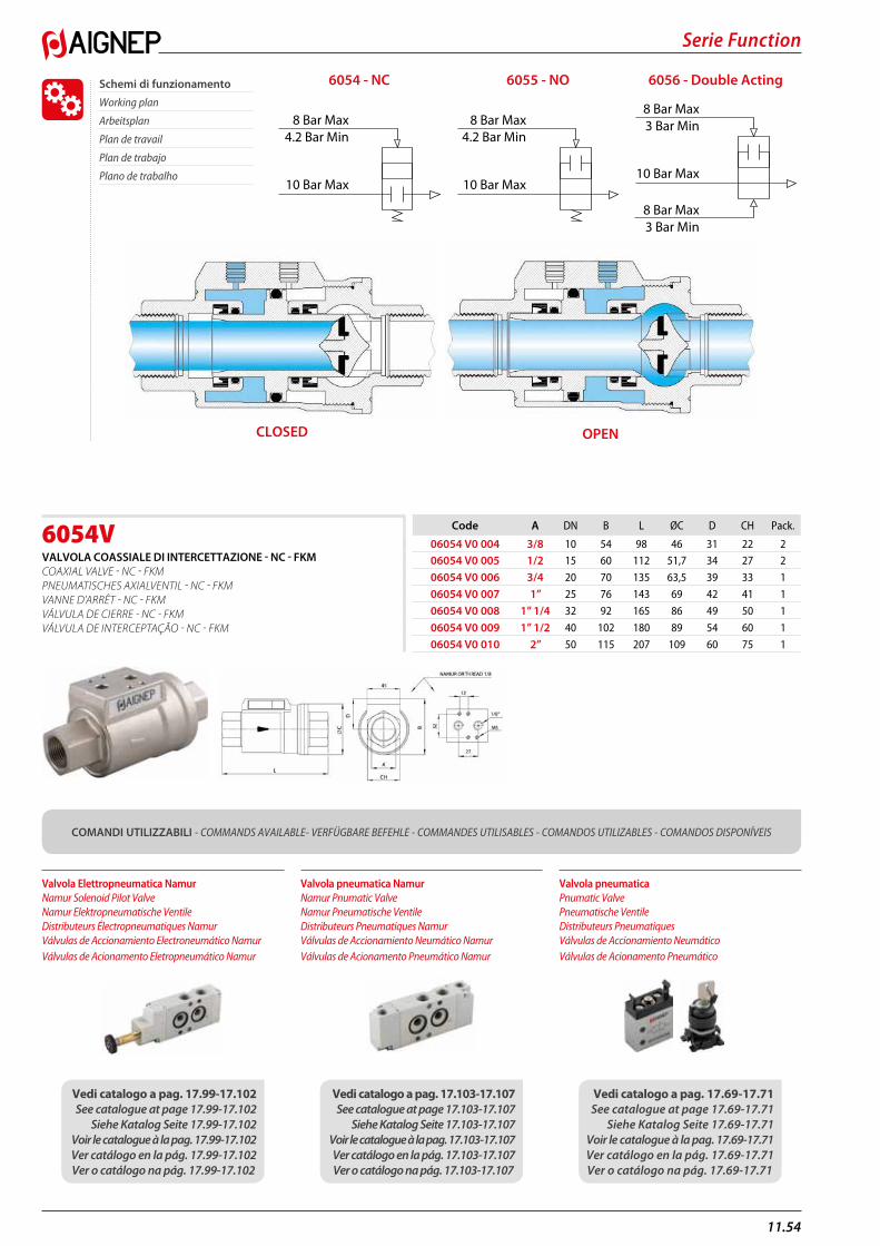
11.54
Serie Function
6054VVALVOLA COASSIALE DI INTERCETTAZIONE - NC - FKM COAXIAL VALVE - NC - FKM PNEUMATISCHES AXIALVENTIL - NC - FKM VANNE D’ARRÊT - NC - FKM VÁLVULA DE CIERRE - NC - FKM VÁLVULA DE INTERCEPTAÇÃO - NC - FKM
Code A DN B L ØC D CH Pack.
06054 V0 004 3/8 10 54 98 46 31 22 206054 V0 005 1/2 15 60 112 51,7 34 27 2
06054 V0 006 3/4 20 70 135 63,5 39 33 1
06054 V0 007 1” 25 76 143 69 42 41 1
06054 V0 008 1” 1/4 32 92 165 86 49 50 1
06054 V0 009 1” 1/2 40 102 180 89 54 60 1
06054 V0 010 2” 50 115 207 109 60 75 1
Schemi di funzionamento
Working plan
Arbeitsplan
Plan de travail
Plan de trabajo
Plano de trabalho10 Bar Max
8 Bar Max4.2 Bar Min
10 Bar Max
8 Bar Max4.2 Bar Min
10 Bar Max
8 Bar Max3 Bar Min
8 Bar Max3 Bar Min
6056 - Double Acting
OPEN
6055 - NO6054 - NC
COMANDI UTILIZZABILI - COMMANDS AVAILABLE- VERFÜGBARE BEFEHLE - COMMANDES UTILISABLES - COMANDOS UTILIZABLES - COMANDOS DISPONÍVEIS
Valvola Elettropneumatica Namur Namur Solenoid Pilot Valve Namur Elektropneumatische Ventile Distributeurs Électropneumatiques Namur Válvulas de Accionamiento Electroneumático Namur Válvulas de Acionamento Eletropneumático Namur
Valvola pneumatica Namur Namur Pnumatic Valve Namur Pneumatische Ventile Distributeurs Pneumatiques Namur Válvulas de Accionamiento Neumático Namur Válvulas de Acionamento Pneumático Namur
Valvola pneumatica Pnumatic Valve Pneumatische Ventile Distributeurs Pneumatiques Válvulas de Accionamiento Neumático Válvulas de Acionamento Pneumático
Vedi catalogo a pag. 17.99-17.102 See catalogue at page 17.99-17.102
Siehe Katalog Seite 17.99-17.102Voir le catalogue à la pag. 17.99-17.102Ver catálogo en la pág. 17.99-17.102Ver o catálogo na pág. 17.99-17.102
Vedi catalogo a pag. 17.103-17.107See catalogue at page 17.103-17.107
Siehe Katalog Seite 17.103-17.107Voir le catalogue à la pag. 17.103-17.107Ver catálogo en la pág. 17.103-17.107Ver o catálogo na pág. 17.103-17.107
Vedi catalogo a pag. 17.69-17.71See catalogue at page 17.69-17.71
Siehe Katalog Seite 17.69-17.71Voir le catalogue à la pag. 17.69-17.71Ver catálogo en la pág. 17.69-17.71Ver o catálogo na pág. 17.69-17.71
CLOSED
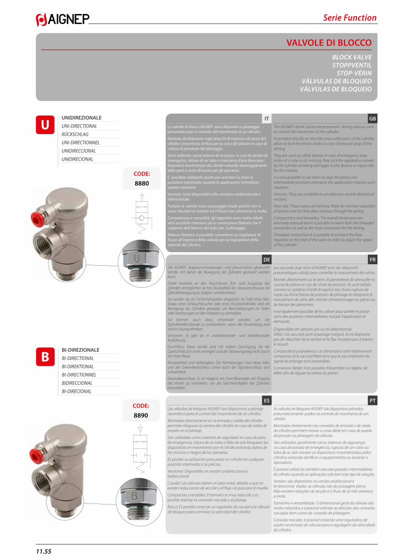
Serie Function
11.55
VALVOLE DI BLOCCOBLOCK VALVESTOPPVENTIL
STOP-VÉRINVÁLVULAS DE BLOQUEO
VÁLVULAS DE BLOQUEIO
UNIDIREZIONALE
UNI-DIRECTIONAL
RÜCKSCHLAG
UNI-DIRECTIONNEL
UNIDIRECCIONAL
UNIDIRECIONAL
BI-DIREZIONALE
BI-DIRECTIONAL
BI-DIREKTIONAL
BI-DIRECTIONNEL
BIDIRECCIONAL
BI-DIRECIONAL
CODE:
8880
CODE:
8890
PTES
FRDE
GBITLe valvole di blocco AIGNEP sono dispositivi a pilotaggio pneumatico per il controllo del movimento di un cilindro.
Montate direttamente sugli attacchi di ingresso ed uscita del cilindro consentono di bloccare la corsa del pistone in caso di caduta di pressione del pilotaggio.
Sono utilizzate come sistema di sicurezza: in caso di arresto di emergenza, rottura di un tubo o mancanza d’aria bloccano i dispositivi movimentati dai cilindri evitando danneggiamenti delle parti o rischi di lesioni per gli operatori.
E’ possibile utilizzarle anche per arrestare lo stelo in posizioni intermedie quando le applicazioni richiedono questa soluzione.
Versioni: sono disponibili nella versione unidirezionale e bidirezionale.
Portata: le valvole sono a passaggio totale poiché non vi sono riduzioni di sezione ed il flusso non attraversa la molla.
Compattezza e versatilità: gli ingombri sono molto ridotti ed è possibile orientare sia la connessione filettata che il supporto dell’attacco del tubo per il pilotaggio.
Attacco filettato: è possibile connettere un regolatore di flusso all’ingresso della valvola per la regolazione della velocità del cilindro.
Les raccords stop-vérin d’AIGNEP sont des dispositifs pneumatiques utilisés pour contrôler le mouvement des vérins.
Montés directement sur le vérin, ils permettent de verrouiller la course du piston en cas de chute de pression. Ils sont utilisés comme un système d’arrêt d’urgence lors d’une rupture de tuyau ou d’une baisse de pression de pilotage en bloquant le mouvement du vérin afin d’éviter d’endommager les pièces ou de blesser des personnes.
Il est également possible de les utiliser pour arrêter le piston dans des positions intermédiaires lorsque l’application le demande.
Disponibles en version uni ou bi-directionnelDébit: Ces raccords sont à passage intégral, ils ne disposent pas de réduction de la section et le flux ne passe pas à travers le ressort.
Compacité et polyvalence: Les dimensions sont relativement compactes et le raccord fileté ainsi que le raccordement du signal de pilotage sont orientables.
Connexion filetée: Il est possible d’assembler un régleur de débit afin de réguler la vitesse du piston.
The AIGNEP’s block valves are pneumatic driving devices used to control the movement of the cylinder.
Assembled directly on the inlet and outlet ports of the cylinder allow to lock the piston stroke in case of pressure drop of the driving.
They are used as safety devices in case of emergency stop, brake of a tube or air missing, they lock the apparatus moved by the cylinder avoiding damages to the devices or injury risks for the runners.
It is also possible to use them to stop the piston into intermediate positions whenever the application requires such solutions.
Versions: They are available in uni-direction and bi-directional versions
Flow rate: These valves are full bore, there do not have reduction of section and the flow does not pass through the spring.
Compactness and Versatility: The overall dimensions are extremely reduced and it is possible to orient both the threaded connection as well as the hose connection for the driving.
Threaded connection: It is possible to connect the flow regulator at the inlet of the valve in order to adjust the speed of the cylinder.
Las válvulas de bloqueo AIGNEP son dispositivos a pilotaje neumático para el control del movimiento de un cilindro.
Montadas directamente en la entrada y salida del cilindro permiten bloquear la carrera del cilindro en caso de caída de presión en el pilotaje.
Son utilizadas como sistemas de seguridad: en caso de paro de emergencia, rotura de un tubo o falta de aire bloquean los dispositivos en movimiento por el cilindro evitando daños de los mismos o riesgos de los operarios.
Es posible su utilización para parar un cilindro en cualquier posición intermedia si se precisa.
Versiones: Disponibles en versión unidireccional y bidireccional.
Caudal: Las válvulas tienen un paso total, debido a que no existen reducciones de sección y el flujo no pasa por el muelle.
Compactas y versátiles: El tamaño es muy reducido y es posible orientar la conexión roscada y el pilotaje.
Rosca: Es posible conectar un regulador de caudal a la válvula de bloqueo para controlar la velocidad del cilindro.
Die AIGNEP Stoppverschraubungen sind pneumatisch gesteuerte Ventile, mit denen die Bewegung des Zylinders gesteuert werden kann.
Direkt montiert an den Anschlüssen (Ein- und Ausgang) des Zylinders ermöglichen sie bei Druckabfall des Steueranschlusses die Zylinderbewegung zu stoppen und blockieren.
Sie werden als ein Sicherheitssystem eingesetzt: im Falle eines Not-Stopp, eines Schlauchbruches oder eines Druckluftabfalles wird die Bewegung des Zylinders gestoppt, um Beschädigungen an Teilen oder Verletzungen an den Arbeitern zu vermeiden.
Sie können auch dazu verwendet werden, um die Zylinderkolbenstange zu positionieren, wenn die Anwendung eine solche Lösung erfordert.
Versionen: Es gibt sie in unidirektionaler- und bidirektionaler Ausführung.
Durchfluss: Diese Ventile sind mit vollem Durchgang, da der Querschnitt sich nicht verringert und der Strömungsweg nicht durch die Feder fliesst.
Kompaktheit und Vielseitigkeit: Die Abmessungen sind relativ klein und der Gewindeanschluss sowie auch der Signalanschluss sind schwenkbar.
Gewindeanschluss: Es ist möglich, ein Durchflussregler am Eingang des Ventils zu montieren, um die Geschwindigkeit des Zylinders einzustellen.
As valvulas de bloqueio AIGNEP são dispositivos pilotados pneumaticamente usados no controle do movimento de um cilindro.
Montadas diretamente nas conexões de entrada e de saída do cilindro permitem travar o curso deste em caso de queda de pressão na pilotagem da válvula.
São utilizadas geralmente como sistemas de segurança: no caso de parada de emergência, ruptura de um tubo ou falta de ar, elas travam os dispositivos movimentados pelos cilindros evitando danificar o equipamentos ou lesionar o operadores.
É possível utilizá-las também executar paradas intermediárias do cilindro quando as aplicações solicitam este tipo de solução.
Versões: são disponíveis na versão unidirecional e bi-direcional. Vazão: as válvulas são de passagem plena. Não existem reduções de secção e o fluxo de ar não atravesa a mola.
Tamanho e versatilidade: O dimensional geral da válvula são muito reduzidos e é possível orientar as direções das conexões roscadas bem como da conexão de pilotagem.
Conexão roscada: é possível conectar uma reguladora de vazão na entrada da válvula para a regulagem da velocidade do cilindro.
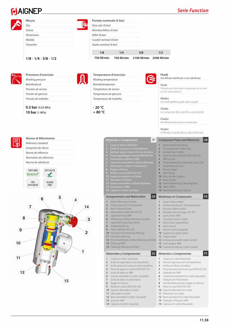
11.56
Serie Function
GBITMateriali e Componenti
1 Corpo in Ottone Nichelato2 Anello di sicurezza in tecnopolimero3 Spintore sgancio tubo in Resina Acetalica4 Pinza d’aggraffaggio in acciaio INOX AISI 3015 Guarnizione a labbro in NBR6 Coperchio orientabile in Ottone Nichelato7 Guarnizione a labbro in Poliuretano8 Seeger in Bronzo9 Molla in acciaio INOX AISI 30210 Supporto otturatore in Ottone11 Otturatore in Ottone12 Basetta orientabile in Ottone Nichelato13 Guarnizioni in NBR 14 Capsula in ottone nichelato
Component Parts and Materials
1 Nickel plated brass Body2 Tecnopolymeric Safety ring3 Acetalic Resin Collect4 Steel Clamping Washer INOX AISI 3015 NBR Lip seal6 Nickel plated brass Orienting Cover Cap7 Polyuretane Lip seal8 Bronze Seeger9 Steel Spring10 Brass Shutter Support11 Brass Shutter12 Nickel plated brass Orienting Base13 NBR O-RING14 Nickel plated brass Capsule
1/8 - 1/4 - 3/8 - 1/2
0.3 bar (0.03 MPa)
10 bar (1 MPa)
- 20 °C+ 80 °C
Fluidi Aria filtrata lubrificata o non lubrificata
Fluids Filtered and lubricated compressed air as well as non lubricated air
Medien Druckluft gefiltert, geölt oder ungeölt.
Fluides Air comprimé, filtré, lubrifié ou non lubrifié.
Fluidos Aire filtrado lubricado o no lubricado
Fluidos Ar filtrado e lubrificado ou não lubrificado
Misura
Size
Grösse
Dimensions
Medida
Tamanho
Pressione d’esercizio
Working pressure
Betriebsdruck
Pression de service
Presión de ejercicio
Pressão de trabalho
Temperatura d’esercizio
Working temperature
Betriebstemperatur
Température de service
Temperatura de ejercicio
Temperatura de trabalho
Bar
Portata nominale (6 bar)
Flow rate (6 bar)
Nenndurchfluss (6 bar)
Débit (6 bar)
Caudal nominal (6 bar)
Vazão nominal (6 bar)
Norma di Riferimento
Reference standard
Entspricht der Norm
Norme de référence
Normativa de referencia
Norma de referência
1907/2006 2011/65/CE
PED 2014/68/UE
SILICON FREE
1/8 1/4 3/8 1/2
750 Nl/min 750 Nl/min 2100 Nl/min 2500 Nl/min
FRDE Matériaux et Composants
1 Corps: laiton nickelé2 Anneau de sécurité: Technopolymère3 Poussoir: Résine acétal4 Rondelle d’accrochage: AISI 3015 Joint à lèvre: NBR 6 Couvercle: laiton nickelé7 Joint à lèvre: polyurétane8 Clips: bronze 9 Ressort: acier inoxydable10 Support du clapet: laiton11 Clapet: laiton12 Embase orientable: laiton nickelé13 Joint torique: NBR 14 Capsule de retenue: Laiton nickelé
Komponenten und Materialien
1 Körper Messing vernickelt2 Sicherungsring Technopolymer3 Rohr Lösering Acetal4 Zahnscheibe Edelstahl AISI 3015 Lippendichtung NBR 6 Abdeckung drehbar Messing vernickelt7 Lippendichtung Polyurethan8 Seegerring Bronze 9 Feder Edelstahl AISI 30210 Verschlussunterstützung Messing11 Verschluss Messing12 Einschraubkörper drehbar Messing vernickelt13 Dichtung NBR 14 Haltering Messing vernickelt
PTESMateriales y Componentes
1 Cuerpo en latón niquelado 2 Anillo de seguridad en tecnopolímero 3 Anillo extracción tubo en resina acetálica 4 Pinza de agarre en acero INOX AISI 301 5 Junta de labio en NBR 6 Cuerpo orientable en latón niquelado7 Junta de labio en poliuretano 8 Seeger en bronce9 Muelle en acero INOX AISI 30210 Soporte obturador en latón 11 Obturador en latón 12 Base orientable en latón niquelado 13 Junta en NBR 14 Cápsula en latón niquelado
Materiais e Componentes
1 Corpo em Latão Niquelado2 Anel de segurança em tecnopolímero3 Anilha em Resina Acetálica4 Pinça de travamento em aço INOX AISI 3015 Vedação em NBR 6 Cobertura orientável em Latão Niquelado7 Vedação em Poliuretano8 Anel de Retenção tipo Seeger em Bronze9 Mola em aço INOX AISI 30210 Suporte obturador em Latão11 Obturador em Latão12 Base orientável em Latão Niquelado13 Vedação O-Ring em NBR 14 Cápsula em Latão Niquelado
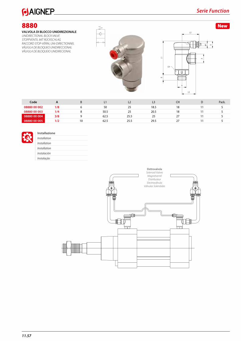
Serie Function
11.57
8880VALVOLA DI BLOCCO UNIDIREZIONALE UNIDIRECTIONAL BLOCK VALVE STOPPVENTIL MIT RÜCKSCHLAG RACCORD STOP-VÉRIN, UNI-DIRECTIONNEL VÁLVULA DE BLOQUEO UNIDIRECCIONAL VÁLVULA DE BLOQUEIO UNIDIRECIONAL
New
CH
L3
L1B
A
ø4
A
L2
U
D
Code A B L1 L2 L3 CH D Pack.
08880 00 002 1/8 6 50 25 18.5 18 11 508880 00 003 1/4 8 50.5 25 20.5 18 11 5
08880 00 004 3/8 9 62.5 25.5 25 27 11 5
08880 00 005 1/2 10 62.5 25.5 29.5 27 11 5
ElettrovalvolaSolenoid Valves
MagnetventilDistributeur
ElectroválvulaVálvulas Solenóides
Installazione
Installation
Installation
Installation
Instalación
Instalação
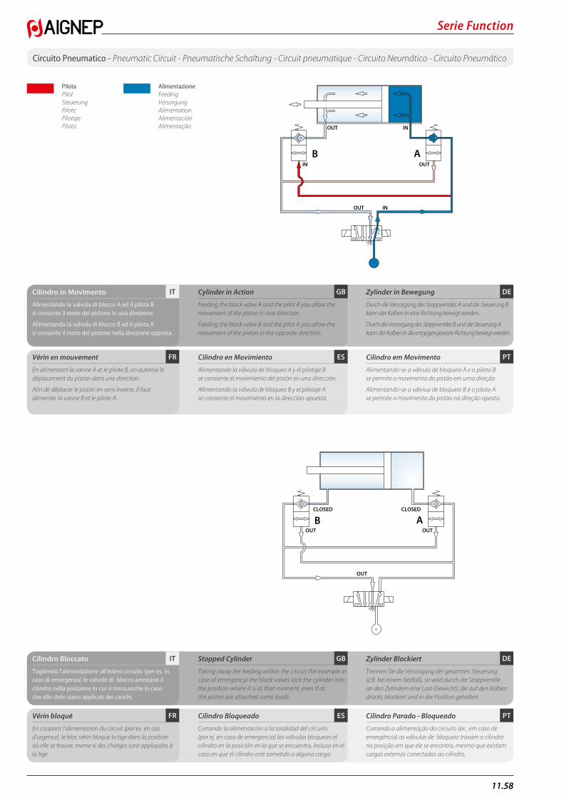
11.58
Serie Function
OUT IN
IN OUT
OUT IN
AB ABCLOSED CLOSED
OUT OUT
OUT
Circuito Pneumatico - Pneumatic Circuit - Pneumatische Schaltung - Circuit pneumatique - Circuito Neumático - Circuito Pneumático
PilotaPilotSteuerungPilotePilotajePiloto
AlimentazioneFeedingVersorgungAlimentationAlimentaciónAlimentação OUT IN
IN OUT
OUT IN
AB ABCLOSED CLOSED
OUT OUT
OUT
PT
PT
ES
ES
FR
FR
DE
DE
GB
GB
IT
IT
Cilindro in Movimento
Alimentando la valvola di blocco A ed il pilota B si consente il moto del pistone in una direzione.
Alimentando la valvola di blocco B ed il pilota A si consente il moto del pistone nella direzione opposta.
Cilindro Bloccato
Togliendo l’alimentazione all’intero circuito (per es. in caso di emergenza) le valvole di blocco arrestano il cilindro nella posizione in cui si trova,anche in caso che allo stelo siano applicati dei carichi.
Vérin en mouvement
En alimentant la vanne A et le pilote B, on autorise le déplacement du piston dans une direction.
Afin de déplacer le piston en sens inverse, il faut alimenter la vanne B et le pilote A.
Vérin bloqué
En coupant l’alimentation du circuit (par ex. en cas d’urgence), le bloc vérin bloque la tige dans la position où elle se trouve, meme si des charges sont appliquées à la tige.
Cylinder in Action
Feeding the block valve A and the pilot B you allow the movement of the piston in one direction.
Feeding the block valve B and the pilot A you allow the movement of the piston in the opposite direction.
Stopped Cylinder
Taking away the feeding within the circuit (for example in case of emergency) the block valves lock the cylinder into the position where it is at that moment, even if at the piston are attached some loads.
Cilindro en Movimiento
Alimentando la válvula de bloqueo A y el pilotaje B se consiente el movimiento del pistón en una dirección.
Alimentando la válvula de bloqueo B y el pilotaje A se consiente el movimiento en la dirección opuesta.
Cilindro Bloqueado
Cortando la alimentación a la totalidad del circuito (por ej. en caso de emergencia) las válvulas bloquean el cilindro en la posición en la que se encuentra, incluso en el caso en que el cilindro este sometido a alguna carga.
Zylinder in Bewegung
Durch die Versorgung des Stoppventiles A und die Steuerung B kann der Kolben in eine Richtung bewegt werden.
Durch die Versorgung des Stoppventiles B und die Steuerung A kann der Kolben in die entgegengesetzte Richtung bewegt werden.
Zylinder Blockiert
Trennen Sie die Versorgung der gesamten Steuerung (z.B. bei einem Notfall), so wird durch die Stoppventile an den Zylindern eine Last (Gewicht), die auf den Kolben drückt, blockiert und in der Position gehalten.
Cilindro em Movimento
Alimentando-se a válvula de bloqueio A e o piloto B se permite o movimento do pistão em uma direção
Alimentando-se a válviua de bloqueio B e o piloto A se permite o movimento do pistão na direção oposta.
Cilindro Parado - Bloqueado
Cortando a alimentação do circuito (ex.: em caso de emergência) as válvulas de bloqueio travam o cilindro na posição em que ele se encontra, mesmo que existam cargas externas conectadas ao cilindro.
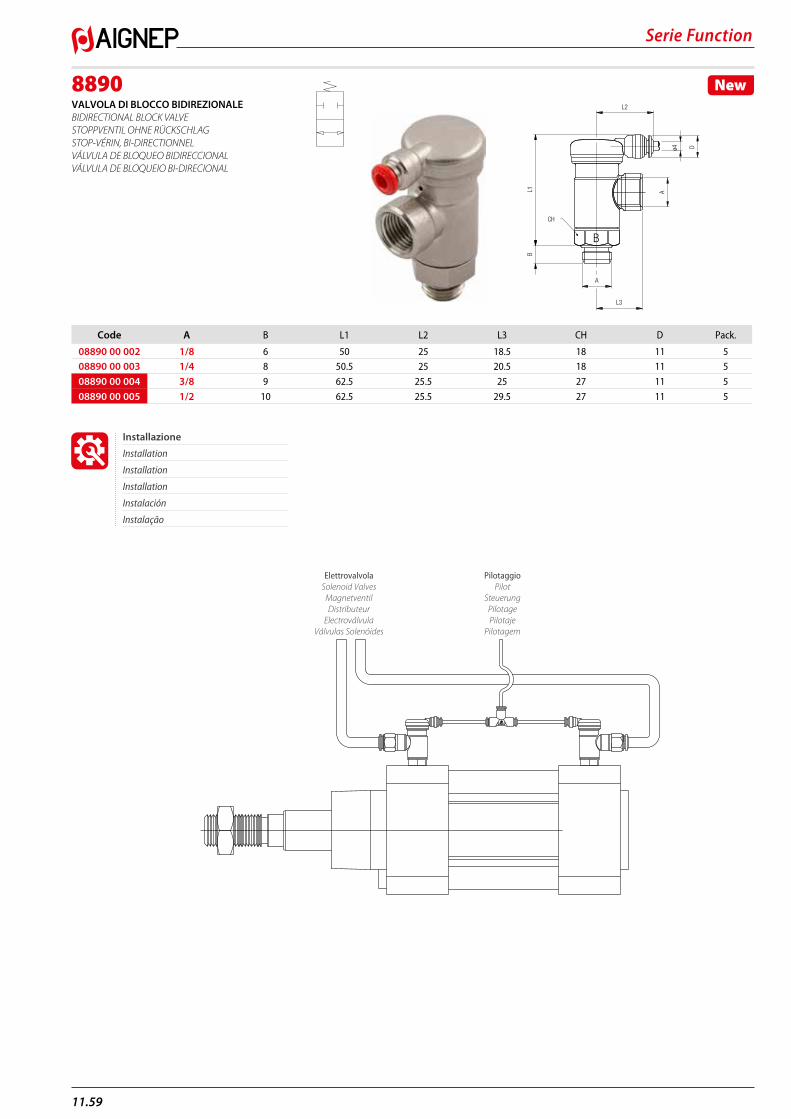
Serie Function
11.59
8890VALVOLA DI BLOCCO BIDIREZIONALE BIDIRECTIONAL BLOCK VALVE STOPPVENTIL OHNE RÜCKSCHLAG STOP-VÉRIN, BI-DIRECTIONNEL VÁLVULA DE BLOQUEO BIDIRECCIONAL VÁLVULA DE BLOQUEIO BI-DIRECIONAL
New
CH
L3
L1B
A
A
L2
B
ø4 D
Code A B L1 L2 L3 CH D Pack.
08890 00 002 1/8 6 50 25 18.5 18 11 508890 00 003 1/4 8 50.5 25 20.5 18 11 5
08890 00 004 3/8 9 62.5 25.5 25 27 11 5
08890 00 005 1/2 10 62.5 25.5 29.5 27 11 5
PilotaggioPilot
SteuerungPilotagePilotaje
Pilotagem
ElettrovalvolaSolenoid Valves
MagnetventilDistributeur
ElectroválvulaVálvulas Solenóides
Installazione
Installation
Installation
Installation
Instalación
Instalação
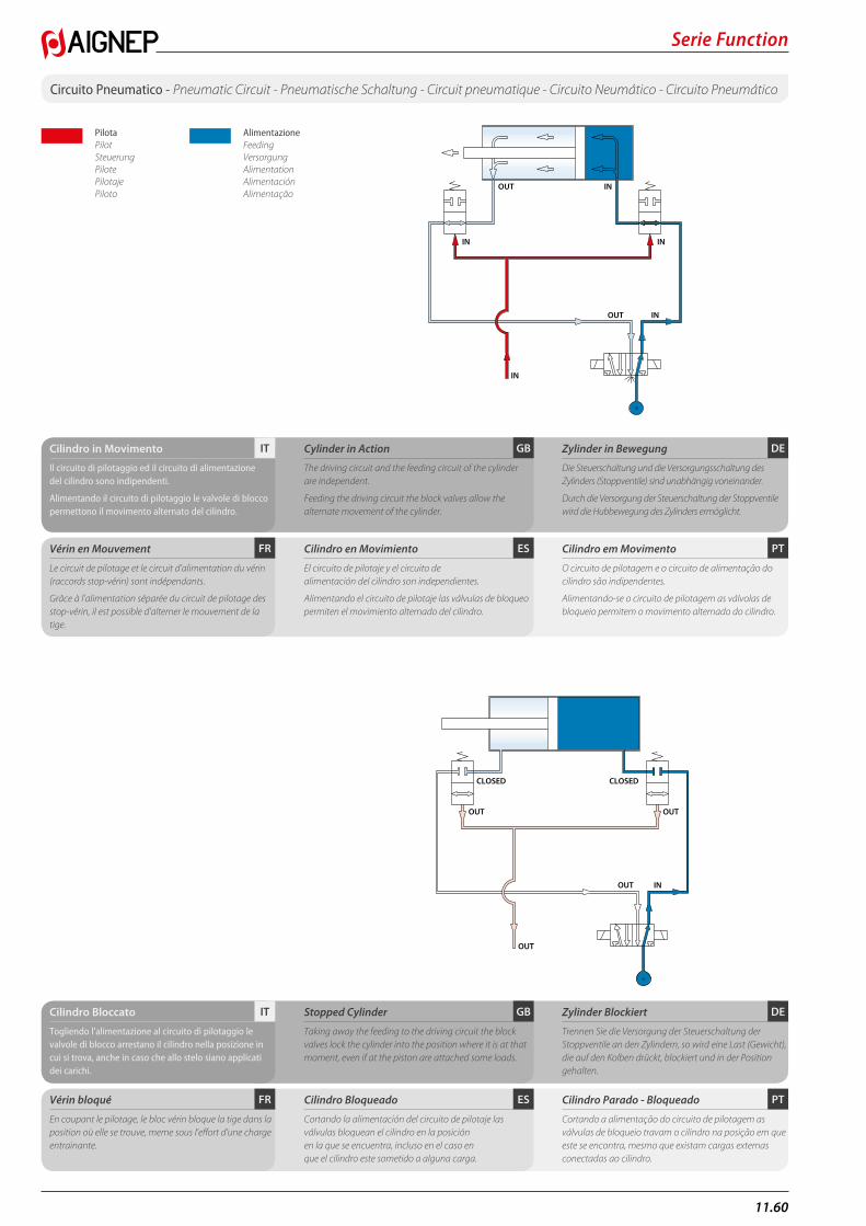
11.60
Serie Function
Circuito Pneumatico - Pneumatic Circuit - Pneumatische Schaltung - Circuit pneumatique - Circuito Neumático - Circuito Pneumático
CLOSED CLOSED
OUT OUT
OUT
OUT IN
IN IN
OUT IN
IN
IN
OUT
PilotaPilotSteuerungPilotePilotajePiloto
AlimentazioneFeedingVersorgungAlimentationAlimentaciónAlimentação
CLOSED CLOSED
OUT OUT
OUT
OUT IN
IN IN
OUT IN
IN
IN
OUT
PT
PT
ES
ES
FR
FR
DE
DE
GB
GB
IT
IT
Cilindro in Movimento
Il circuito di pilotaggio ed il circuito di alimentazione del cilindro sono indipendenti.
Alimentando il circuito di pilotaggio le valvole di blocco permettono il movimento alternato del cilindro.
Cilindro Bloccato
Togliendo l’alimentazione al circuito di pilotaggio le valvole di blocco arrestano il cilindro nella posizione in cui si trova, anche in caso che allo stelo siano applicati dei carichi.
Vérin en Mouvement
Le circuit de pilotage et le circuit d’alimentation du vérin (raccords stop-vérin) sont indépendants.
Grâce à l’alimentation séparée du circuit de pilotage des stop-vérin, il est possible d’alterner le mouvement de la tige.
Vérin bloqué
En coupant le pilotage, le bloc vérin bloque la tige dans la position où elle se trouve, meme sous l’effort d’une charge entrainante.
Cylinder in Action
The driving circuit and the feeding circuit of the cylinder are independent.
Feeding the driving circuit the block valves allow the alternate movement of the cylinder.
Stopped Cylinder
Taking away the feeding to the driving circuit the block valves lock the cylinder into the position where it is at that moment, even if at the piston are attached some loads.
Cilindro en Movimiento
El circuito de pilotaje y el circuito de alimentación del cilindro son independientes.
Alimentando el circuito de pilotaje las válvulas de bloqueo permiten el movimiento alternado del cilindro.
Cilindro Bloqueado
Cortando la alimentación del circuito de pilotaje las válvulas bloquean el cilindro en la posición en la que se encuentra, incluso en el caso en que el cilindro este sometido a alguna carga.
Zylinder in Bewegung
Die Steuerschaltung und die Versorgungsschaltung des Zylinders (Stoppventile) sind unabhängig voneinander.
Durch die Versorgung der Steuerschaltung der Stoppventile wird die Hubbewegung des Zylinders ermöglicht.
Zylinder Blockiert
Trennen Sie die Versorgung der Steuerschaltung der Stoppventile an den Zylindern, so wird eine Last (Gewicht), die auf den Kolben drückt, blockiert und in der Position gehalten.
Cilindro em Movimento
O circuito de pilotagem e o circuito de alimentação do cilindro são indipendentes.
Alimentando-se o circuito de pilotagem as válvolas de bloqueio permitem o movimento alternado do cilindro.
Cilindro Parado - Bloqueado
Cortando a alimentação do circuito de pilotagem as válvulas de bloqueio travam o cilindro na posição em que este se encontra, mesmo que existam cargas externas conectadas ao cilindro.
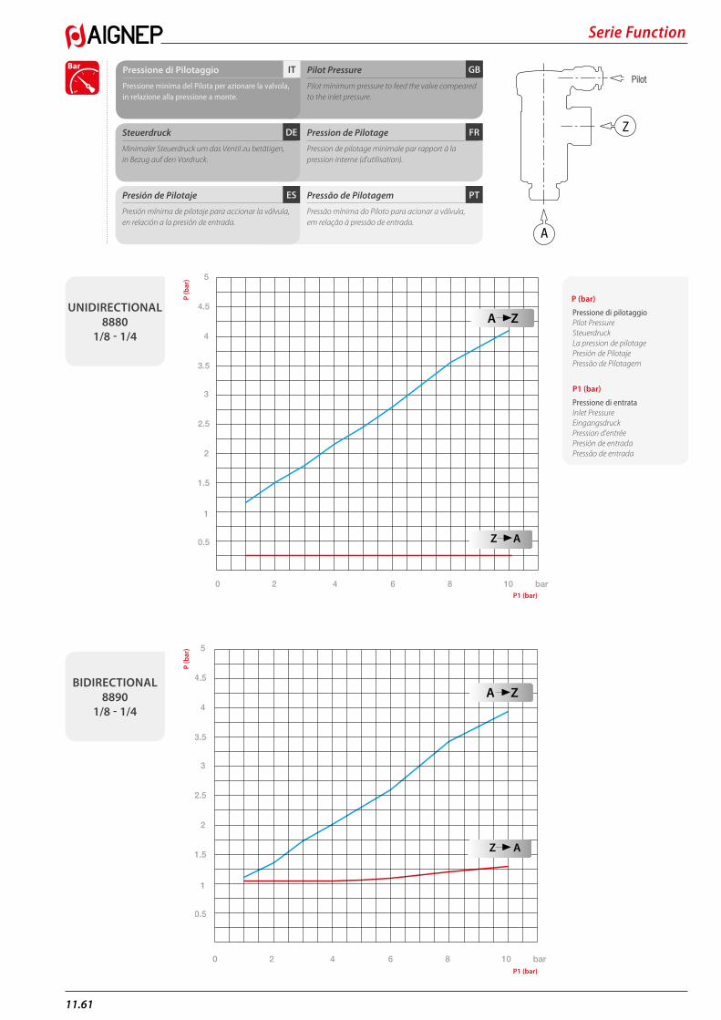
Serie Function
11.61
Z
A
Pilot
PTES
FRDE
GBITPressione di Pilotaggio
Pressione minima del Pilota per azionare la valvola, in relazione alla pressione a monte.
Pilot Pressure
Pilot minimum pressure to feed the valve compeared to the inlet pressure.
Pression de Pilotage
Pression de pilotage minimale par rapport à la pression interne (d’utilisation).
Presión de Pilotaje
Presión mínima de pilotaje para accionar la válvula, en relación a la presión de entrada.
Steuerdruck
Minimaler Steuerdruck um das Ventil zu betätigen, in Bezug auf den Vordruck.
Pressão de Pilotagem
Pressão mínima do Piloto para acionar a válvula, em relação à pressão de entrada.
0.5
1
1.5
2
2.5
3
3.5
4
5
4.5
A Z
Z A
0 2 4 6 8 10 bar
Bar
UNIDIRECTIONAL8880
1/8 - 1/4
BIDIRECTIONAL 8890
1/8 - 1/4
P (bar)
Pressione di pilotaggioPilot PressureSteuerdruckLa pression de pilotagePresión de PilotajePressão de Pilotagem
P1 (bar)
Pressione di entrataInlet PressureEingangsdruckPression d’entréePresión de entrada Pressão de entrada
A Z
Z A
0.5
1
1.5
2
2.5
3
3.5
4
5
4.5
0 2 4 6 8 10 bar
P (b
ar)
P (b
ar)
P1 (bar)
P1 (bar)
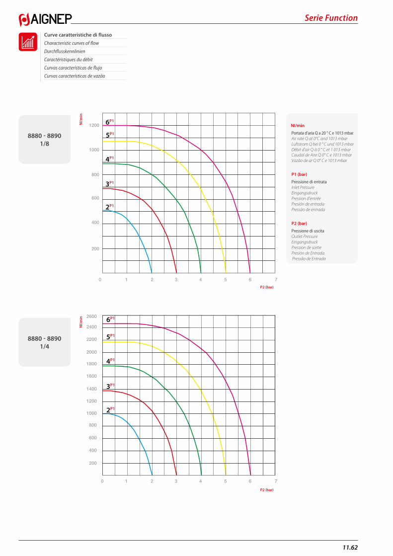
11.62
Serie Function
Curve caratteristiche di flusso
Characteristic curves of flow
Durchflusskennlinien
Caractéristiques du débit
Curvas características de flujo
Curvas características de vazão
2400
2000
1600
1200
800
400
600
1000
1400
1800
2200
2600
200
2P1
3P1
4P1
5P1
6P1
0 1 2 3 4 5 6 7
1200
1000
800
600
400
200
0 1 2 3 4 5 6 7
2P1
3P1
4P1
6P1
5P1
NI/m
inN
I/min
P2 (bar)
P2 (bar)
8880 - 8890 1/8
8880 - 88901/4
NI/min
Portata d’aria Q a 20 ° C e 1013 mbarAir rate Q at 0°C and 1013 mbarLuftstrom Q bei 0 ° C und 1013 mbarDébit d’air Q à 0 ° C et 1 013 mbarCaudal de Aire Q 0° C e 1013 mbarVazão de ar Q 0° C e 1013 mbar
P1 (bar)
Pressione di entrataInlet PressureEingangsdruckPression d’entréePresión de entrada Pressão de entrada
P2 (bar)
Pressione di uscitaOutlet PressureEingangsdruckPression de sortie Presión de Entrada Pressão de Entrada
AIGNEP SPAVia Don G. Bazzoli - 34 25070 Bione (BS) ITALY
T: +39 0365 896626 F: +39 0365 896561
AIGNEP USA LLC7121 Loblolly Pine BlvdFairview, TN 37062 U.S.A.
T: +1 615 771 6650 F: +1 615 771 0926
AIGNEP LATAM
Sede:Calle 15 N 27-78 Local 2Sec. Paloquemao - 111411 BogotaCOLOMBIA
T: +57 1 37 52 50 1 T: +57 1 37 52 50 8
Sucursal:Calle 6 SUR 52-80 Local 19Cc. El Rodeo - 0520024 MedellìnCOLOMBIA
T: +57 4 58 70 90 1
[email protected] IBERICA SA Pol. Ind. el Tortuguer “Can Prat”Naves 23 y 24 08691 Monistrol de Montserrat - Barcelona SPAIN
T: +34 93 828 47 36 F: +34 93 828 44 32
AIGNEP FRANCE SARL 2, Avenue des Amèthystes 44338 Nantes Cedex 3 FRANCE
T: +33 02 72 24 26 50 F: +33 02 72 24 26 51
AIGNEP DO BRASIL COMERCIO DE COMPONENTES PARA AUTOMAÇÃO LTDA Rua Campos Mello, 185Vila Mathias - 11015-011 - Santos/SP BRASIL
T: +55 13 2138 4049 F: +55 13 2138 4052
AIGNEP AG Industriestrasse 22A2545 Selzach SWITZERLAND
T: +41 32 342 09 09 F: +41 32 342 09 11
AIGNEP (Wuxi) FLUID TECHNOLOGY CO., LT D. NO 8, Yanggong Road, Nanhu Main Road Wuxi, Jiangsu. CHINA
T: 0510-8544 1923 F: 0510-8540 0223
Ag
gior
nam
ento
- U
pdat
ed -
Sta
nd -
Mise
a jo
ur -
Actu
aliz
ació
n - A
tual
izaç
ão: 1
1/20
18
Aig
nep
si r
iser
va il
dir
itto
di v
aria
re m
odel
li e
ing
omb
ri s
enza
pre
avvi
so.
Aig
nep
rese
rves
the
right
to v
ary
mod
els a
nd d
imen
sion
s with
out n
otic
e.A
igne
p be
hält
sich
das
Rec
ht v
or, D
aten
ohn
e A
nkün
digu
ng z
u än
dern
.A
igne
p se
rése
rve
le d
roit
de m
odifi
er le
s don
nées
sans
pré
avis
.A
igne
p se
rese
rva
el d
erec
ho d
e m
odifi
car m
odel
os y
dim
ensi
ones
sin
prev
io a
viso
.A
igne
p re
serv
a-se
o d
ireito
de
alte
rar o
s mod
elos
e d
imen
sões
sem
pré
vio
avis
o.